JP3768486B2 - Micro fluid handling equipment - Google Patents
Micro fluid handling equipment Download PDFInfo
- Publication number
- JP3768486B2 JP3768486B2 JP2003077034A JP2003077034A JP3768486B2 JP 3768486 B2 JP3768486 B2 JP 3768486B2 JP 2003077034 A JP2003077034 A JP 2003077034A JP 2003077034 A JP2003077034 A JP 2003077034A JP 3768486 B2 JP3768486 B2 JP 3768486B2
- Authority
- JP
- Japan
- Prior art keywords
- sealing
- flow path
- external environment
- handling device
- sample
- Prior art date
- Legal status (The legal status is an assumption and is not a legal conclusion. Google has not performed a legal analysis and makes no representation as to the accuracy of the status listed.)
- Expired - Fee Related
Links
Images


Classifications
-
- B—PERFORMING OPERATIONS; TRANSPORTING
- B01—PHYSICAL OR CHEMICAL PROCESSES OR APPARATUS IN GENERAL
- B01F—MIXING, e.g. DISSOLVING, EMULSIFYING OR DISPERSING
- B01F25/00—Flow mixers; Mixers for falling materials, e.g. solid particles
- B01F25/40—Static mixers
- B01F25/42—Static mixers in which the mixing is affected by moving the components jointly in changing directions, e.g. in tubes provided with baffles or obstructions
- B01F25/43—Mixing tubes, e.g. wherein the material is moved in a radial or partly reversed direction
- B01F25/433—Mixing tubes wherein the shape of the tube influences the mixing, e.g. mixing tubes with varying cross-section or provided with inwardly extending profiles
-
- B—PERFORMING OPERATIONS; TRANSPORTING
- B01—PHYSICAL OR CHEMICAL PROCESSES OR APPARATUS IN GENERAL
- B01L—CHEMICAL OR PHYSICAL LABORATORY APPARATUS FOR GENERAL USE
- B01L3/00—Containers or dishes for laboratory use, e.g. laboratory glassware; Droppers
- B01L3/50—Containers for the purpose of retaining a material to be analysed, e.g. test tubes
- B01L3/502—Containers for the purpose of retaining a material to be analysed, e.g. test tubes with fluid transport, e.g. in multi-compartment structures
- B01L3/5027—Containers for the purpose of retaining a material to be analysed, e.g. test tubes with fluid transport, e.g. in multi-compartment structures by integrated microfluidic structures, i.e. dimensions of channels and chambers are such that surface tension forces are important, e.g. lab-on-a-chip
- B01L3/50273—Containers for the purpose of retaining a material to be analysed, e.g. test tubes with fluid transport, e.g. in multi-compartment structures by integrated microfluidic structures, i.e. dimensions of channels and chambers are such that surface tension forces are important, e.g. lab-on-a-chip characterised by the means or forces applied to move the fluids
-
- B—PERFORMING OPERATIONS; TRANSPORTING
- B01—PHYSICAL OR CHEMICAL PROCESSES OR APPARATUS IN GENERAL
- B01F—MIXING, e.g. DISSOLVING, EMULSIFYING OR DISPERSING
- B01F25/00—Flow mixers; Mixers for falling materials, e.g. solid particles
- B01F25/40—Static mixers
- B01F25/42—Static mixers in which the mixing is affected by moving the components jointly in changing directions, e.g. in tubes provided with baffles or obstructions
- B01F25/43—Mixing tubes, e.g. wherein the material is moved in a radial or partly reversed direction
- B01F25/433—Mixing tubes wherein the shape of the tube influences the mixing, e.g. mixing tubes with varying cross-section or provided with inwardly extending profiles
- B01F25/4331—Mixers with bended, curved, coiled, wounded mixing tubes or comprising elements for bending the flow
-
- B—PERFORMING OPERATIONS; TRANSPORTING
- B01—PHYSICAL OR CHEMICAL PROCESSES OR APPARATUS IN GENERAL
- B01F—MIXING, e.g. DISSOLVING, EMULSIFYING OR DISPERSING
- B01F33/00—Other mixers; Mixing plants; Combinations of mixers
- B01F33/30—Micromixers
-
- B—PERFORMING OPERATIONS; TRANSPORTING
- B01—PHYSICAL OR CHEMICAL PROCESSES OR APPARATUS IN GENERAL
- B01L—CHEMICAL OR PHYSICAL LABORATORY APPARATUS FOR GENERAL USE
- B01L3/00—Containers or dishes for laboratory use, e.g. laboratory glassware; Droppers
- B01L3/50—Containers for the purpose of retaining a material to be analysed, e.g. test tubes
- B01L3/502—Containers for the purpose of retaining a material to be analysed, e.g. test tubes with fluid transport, e.g. in multi-compartment structures
- B01L3/5027—Containers for the purpose of retaining a material to be analysed, e.g. test tubes with fluid transport, e.g. in multi-compartment structures by integrated microfluidic structures, i.e. dimensions of channels and chambers are such that surface tension forces are important, e.g. lab-on-a-chip
- B01L3/502738—Containers for the purpose of retaining a material to be analysed, e.g. test tubes with fluid transport, e.g. in multi-compartment structures by integrated microfluidic structures, i.e. dimensions of channels and chambers are such that surface tension forces are important, e.g. lab-on-a-chip characterised by integrated valves
-
- B—PERFORMING OPERATIONS; TRANSPORTING
- B01—PHYSICAL OR CHEMICAL PROCESSES OR APPARATUS IN GENERAL
- B01L—CHEMICAL OR PHYSICAL LABORATORY APPARATUS FOR GENERAL USE
- B01L2200/00—Solutions for specific problems relating to chemical or physical laboratory apparatus
- B01L2200/06—Fluid handling related problems
- B01L2200/0621—Control of the sequence of chambers filled or emptied
-
- B—PERFORMING OPERATIONS; TRANSPORTING
- B01—PHYSICAL OR CHEMICAL PROCESSES OR APPARATUS IN GENERAL
- B01L—CHEMICAL OR PHYSICAL LABORATORY APPARATUS FOR GENERAL USE
- B01L2300/00—Additional constructional details
- B01L2300/08—Geometry, shape and general structure
- B01L2300/0809—Geometry, shape and general structure rectangular shaped
- B01L2300/0816—Cards, e.g. flat sample carriers usually with flow in two horizontal directions
-
- B—PERFORMING OPERATIONS; TRANSPORTING
- B01—PHYSICAL OR CHEMICAL PROCESSES OR APPARATUS IN GENERAL
- B01L—CHEMICAL OR PHYSICAL LABORATORY APPARATUS FOR GENERAL USE
- B01L2300/00—Additional constructional details
- B01L2300/08—Geometry, shape and general structure
- B01L2300/0861—Configuration of multiple channels and/or chambers in a single devices
- B01L2300/0867—Multiple inlets and one sample wells, e.g. mixing, dilution
-
- B—PERFORMING OPERATIONS; TRANSPORTING
- B01—PHYSICAL OR CHEMICAL PROCESSES OR APPARATUS IN GENERAL
- B01L—CHEMICAL OR PHYSICAL LABORATORY APPARATUS FOR GENERAL USE
- B01L2300/00—Additional constructional details
- B01L2300/08—Geometry, shape and general structure
- B01L2300/0861—Configuration of multiple channels and/or chambers in a single devices
- B01L2300/087—Multiple sequential chambers
-
- B—PERFORMING OPERATIONS; TRANSPORTING
- B01—PHYSICAL OR CHEMICAL PROCESSES OR APPARATUS IN GENERAL
- B01L—CHEMICAL OR PHYSICAL LABORATORY APPARATUS FOR GENERAL USE
- B01L2300/00—Additional constructional details
- B01L2300/08—Geometry, shape and general structure
- B01L2300/0887—Laminated structure
-
- B—PERFORMING OPERATIONS; TRANSPORTING
- B01—PHYSICAL OR CHEMICAL PROCESSES OR APPARATUS IN GENERAL
- B01L—CHEMICAL OR PHYSICAL LABORATORY APPARATUS FOR GENERAL USE
- B01L2400/00—Moving or stopping fluids
- B01L2400/06—Valves, specific forms thereof
- B01L2400/0694—Valves, specific forms thereof vents used to stop and induce flow, backpressure valves
Landscapes
- Chemical & Material Sciences (AREA)
- Chemical Kinetics & Catalysis (AREA)
- Dispersion Chemistry (AREA)
- Health & Medical Sciences (AREA)
- Analytical Chemistry (AREA)
- General Health & Medical Sciences (AREA)
- Hematology (AREA)
- Clinical Laboratory Science (AREA)
- Automatic Analysis And Handling Materials Therefor (AREA)
- Physical Or Chemical Processes And Apparatus (AREA)
- Micromachines (AREA)
Description
【0001】
【発明の属する技術分野】
この発明は、毛細管現象によって流体を流動させることができる流路を備えた微小流体取扱装置に関するものであり、例えば、インテグレーテッド・ケミストリと呼ばれる技術分野で使用されるマイクロチップ等の微小流体取扱装置であって、複数種の微量な液状の試料を移動,混合等するために使用されたり、POC(Point of care)検査用デバイスとして使用される微小流体取扱装置に関するものである。
【0002】
【従来の技術】
近年、ガラスやプラスチックのマイクロチップの内部に数1μmから1000μm程度の微細溝を作り、その微細溝を液体の流路や反応槽,分離精製検出槽として使用して、マイクロチップに複雑な化学システムを集積するインテグレーテッド・ケミストリと呼ばれる技術が知られている。このインテグレーテッド・ケミストリによれば、様々な試験に使用される微細溝が形成されたマイクロチップ(Lab−on−chip)を分析化学に限定して使用する場合にはμ−TAS(Total Analytical System)と呼称し、また、マイクロチップを反応だけに限定して使用する場合にはマイクロリアクターと呼称するようになっている。このインテグレーテッド・ケミストリは、分析等の各種試験を行う場合、空間が小さいので拡散分子の輸送時間が短くてすみ、また、液相の熱容量が極めて小さい等の優れた利点を有しているため、ミクロ空間を分析や化学合成等に利用しようとする技術分野において注目を集めている。なお、ここでいう試験とは、分析,測定,合成,分解,混合,分子輸送,溶媒抽出,固相抽出,相分離,相合流,分子補捉,培養,加熱,冷却等の操作・手段を単一又は複合させて行うものである。
【0003】
このようなインテグレーテッド・ケミストリにおいては、ガラスやプラスチックのチップの内部に形成された一辺が1μm〜1000μm程度の流路幅及び流路高さの液体流路を開閉し、その微細な液体流路内に試料を流動させる必要がある。そのため、微細な液体流路を開閉する様々なバルブ構造が既に案出されている。
【0004】
例えば、特許文献1に開示された技術は、液体流路の分岐部等に光応答性物質からなる可動膜を配置し、この可動膜にレーザー光を照射することにより可動膜を変形させ、これにより液体流路の流れ制御を行うようになっている。また、特許文献2に開示された技術は、毛細管状流路の途中にゲル室を形成し、このゲル室内に感温性ゲルを充填して、その感温性ゲルを加熱して膨張させることにより、毛細管状流路内に感温性ゲルを突出させ、これにより流路断面積を変化させるようになっている。また、特許文献3に開示された技術は、微細な液体流路の途中にソレノイドバルブを配置し、このソレノイドバルブを開閉することにより、微量な試料の流れを制御するようになっている。
【0005】
【特許文献1】
特開2002−36196号公報(第1頁,図1及び図2参照)
【特許文献2】
特開2002−66399号公報(段落番号0050,図1及び図2参照)
【特許文献3】
特開2002−282682号公報(段落番号0046〜0049及び図3参照)
【0006】
【発明が解決しようとする課題】
しかし、前述の特許文献1〜3に記載された各従来技術は、微小な流路断面の液体流路の途中にバルブ機構を設置する態様であり、加工が困難であるため、このようなバルブ機構を備えたプレート(例えば、マイクロチップ)の製品価格が極めて高価であるという問題を有していた。
【0007】
そこで、本発明は、複数種の微量液体(微小試料)の流れ制御を外部の駆動源に依存することがなく簡単に行え、しかもPOC検査に好適で安価な微小流体取扱装置を提供することを目的とする。
【0008】
【課題を解決するための手段】
請求項1の発明は、流体が毛細管現象により移動する形状に形成された流路を内部に有する微小流体取扱装置に関するものである。そして、この発明に係る微小流体取扱装置は、前記流路の一端部が外部の環境に連絡され、前記流路の他端部が封止部によって外部の環境と遮断され、前記封止部の少なくとも一部が前記流路の他端部から開放されることにより、前記流路の他端部が外部の環境と連絡されるようになっている。また、この発明に係る微小流体取扱装置において、前記封止部は封止用突起を有し、この封止用突起を押し倒すことによって前記封止部が破断され、前記流路の他端部を外部の環境と連絡することを特徴としている。
【0009】
請求項2の発明は、流体が毛細管現象により移動する形状に形成された流路を内部に有する微小流体取扱装置に関するものである。この発明に係る微小流体取扱装置は、前記流路の一端部には流体を貯蔵可能な貯蔵部が形成され、前記流路の一端部が前記貯蔵部を介して外部の環境に連絡され、前記流路の他端部には封止部が形成され、前記流路の他端部が前記封止部を介して外部の環境と遮断されるようになっている。そして、この発明に係る微小流体取扱装置は、前記封止部の少なくとも一部が前記流路の他端部から開放されることにより、前記流路の他端部が外部の環境と連絡されるようになっている。また、この発明に係る微小流体取扱装置において、前記封止部は封止用突起を有し、この封止用突起を押し倒すことによって前記封止部が破断され、前記流路の他端部を外部の環境と連絡することを特徴としている。
【0010】
請求項3の発明は、流体が毛細管現象により移動する形状に形成された流路を内部に有する微小流体取扱装置に関するものである。この発明に係る微小流体取扱装置は、前記流路の両端部に封止部が形成され、この封止部によって前記流路の内部と外部の環境とが遮断され、前記各々の封止部の少なくとも一部が前記流路の端部から開放されることにより、前記流路の端部が外部の環境と連絡されるようになっている。そして、この発明に係る微小流体取扱装置において、前記封止部は封止用突起を有し、この封止用突起を押し倒すことによって前記封止部が破断され、前記流路の端部を外部の環境と連絡することを特徴としている。
【0011】
請求項4の発明は、請求項3の発明に係る微小流体取扱装置において、前記流路の両端部の少なくとも一方の端部に流体を貯蔵可能な貯蔵部が形成され、前記少なくとも一方の端部の封止部が開放されることにより、前記少なくとも一方の端部が前記貯蔵部を介して外部の環境と連絡されることを特徴とするものである。
【0012】
請求項5の発明は、流体が毛細管現象により移動する形状に形成された流路を内部に少なくとも3つ有する微小流体取扱装置に関するものである。この発明の微小流体取扱装置において、前記少なくとも3つの流路の各々の一端部は第1の交点で互いに連絡され、前記少なくとも3つの流路のうち、少なくとも1つの流路の他端部は封止部によって外部の環境と遮断されるとともに、前記少なくとも1つの流路の他端部以外の他端部は外部の環境に各々連絡されている。そして、この発明の微小流体取扱装置は、前記封止部の少なくとも一部が前記流路の他端部から開放されることにより、前記少なくとも1つの流路の他端部が外部の環境と連絡されるようになっている。また、この発明に係る微小流体取扱装置において、前記封止部は封止用突起を有し、この封止用突起を押し倒すことによって前記封止部が破断され、前記流路の他端部を外部の環境と連絡することを特徴としている。
【0013】
請求項6の発明は、請求項5の発明に係る微小流体取扱装置において、前記少なくとも3つの流路の他端部の少なくとも1つに前記流体を貯蔵する貯蔵部が形成されていることを特徴としている。
【0014】
請求項7の発明は、流体が毛細管現象により移動する形状に形成された主流路を内部に有し、流体が毛細管現象により移動する形状に形成された副流路を内部に少なくとも1つ有する微小流体取扱装置に関するものである。この発明の微小流体取扱装置において、前記主流路の一端部は外部の環境に連絡されるとともに、前記主流路の他端部は封止部によって外部の環境と遮断されている。そして、前記少なくとも1つの副流路の一端部は、前記主流路の一端部と他端部との間で前記主流路と連絡されている。また、前記少なくとも1つの副流路の他端部は、外部の環境と連絡されている。そして、前記封止部の少なくとも一部が前記主流路の他端部から開放されることにより、前記主流路の他端部が外部の環境と連絡されるようになっている。また、この発明に係る微小流体取扱装置において、前記封止部は封止用突起を有し、この封止用突起を押し倒すことによって前記封止部が破断され、前記流路の他端部を外部の環境と連絡することを特徴としている。
【0015】
請求項8の発明は、流体が毛細管現象により移動する形状に形成された主流路と、流体が毛細管現象により移動する形状に形成された第1の副流路と、流体が毛細管現象により移動する形状に形成された第2の副流路とを内部に少なくとも有する微小流体取扱装置に関するものである。この発明の微小流体取扱装置において、前記主流路の一端部は外部の環境に連絡されるとともに、前記主流路の他端部は封止部によって外部の環境と遮断されている。また、この発明の微小流体取扱装置において、前記第1の副流路は、その一端部が前記主流路の一端部と他端部との間で前記主流路と連絡されるとともに、その他端部が外部の環境と連絡されている。また、前記第2の副流路は、その一端部が前記第1の副流路の一端部と他端部との間で前記第1の副流路と連絡されるとともに、その他端部が外部の環境と連絡されている。そして、この発明の微小流体取扱装置は、前記封止部の少なくとも一部が前記主流路の他端部から開放されることにより、前記主流路の他端部が外部の環境と連絡されるようになっている。また、この発明に係る微小流体取扱装置において、前記封止部は封止用突起を有し、この封止用突起を押し倒すことによって前記封止部が破断され、前記流路の他端部を外部の環境と連絡することを特徴としている。
【0016】
請求項9の発明は、流体が毛細管現象により移動する形状に形成された流路を内部に複数有する微小流体取扱装置に関するものである。この発明の微小流体取扱装置において、前記複数の流路は、所定のパターンをもって連絡され、前記複数の流路の端部のうち、外部の環境と連絡する流路の端部の少なくとも1つは封止部によって外部の環境と遮断され、
前記封止部の少なくとも一部が前記流路の端部から開放されることにより、前記流路の端部が外部の環境と連絡されるようになっている。また、この発明に係る微小流体取扱装置において、前記封止部は封止用突起を有し、この封止用突起を押し倒すことによって前記封止部が破断され、前記流路の端部を外部の環境と連絡することを特徴としている。
【0017】
【発明の実施の形態】
以下、本発明の実施の形態を図面に基づき詳述する。尚、以下の各実施の形態は、インテグレーテッド・ケミストリと呼ばれる技術分野で使用されるマイクロチップ等の微小流体取扱装置に関するものであり、特に複数種の微量な試料を混合等したり、POC検査デバイスとして使用される微小流体取扱装置に関するものである。
【0018】
[第1の実施の形態]
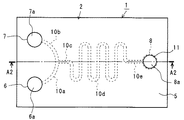
図1〜図4は、本発明の第1の実施の形態に係る微小流体取扱装置1を示すものである。このうち、図1は、微小流体取扱装置1の裏面図であり、後述する第2プレート部材3を部分的に取り除いて示す微小流体取扱装置1の裏面図(図2のY1方向矢視図)である。また、図2は、図1のA1−A1線に沿って切断して示す微小流体取扱装置1の断面図である。また、図3は、微小流体取扱装置1の平面図(図2のY2方向矢視図)である。また、図4は、微小流体取扱装置1の使用状態を示す図であり、図3のA2−A2線に沿って切断して示す微小流体取扱装置1の断面図である。
【0019】
これらの図に示すように、微小流体取扱装置1は、第1プレート部材2と、この第1プレート部材2の平滑な第1の表面4に重ねて固定される第2プレート部材3とを備えている。この微小流体取扱装置1を構成する第1プレート部材2と第2プレート部材3は、例えば、ポリカーボネート(PC),ポリメタクリル酸メチル(PMMA)等で形成されている。尚、微小流体取扱装置1を形成する材料は、これらに限定されず、PC,PMMA以外の合成樹脂又はガラス材料若しくは金属材料等の無機材料を用いることもできる。
【0020】
第1プレート部材2は、その第2の表面5側から第1の表面4側に貫通する貫通孔6a,7aが中心線CLに対して対称の位置に一対形成されている。また、この第1プレート部材2の貫通孔6a,7aから離間した中心線CL上には、第1プレート部材2の第1の表面4側から第2の表面5側に向かって凹部8aが形成されている。そして、これら貫通孔6a,7aと凹部8aとを連通する微細溝(毛細管現象を生じる流路を構成する凹部)10が第1プレート部材2の第1の表面4に形成されている。
【0021】
この第1プレート部材2の第1の表面4の微細溝10は、一対の貫通孔6a,7aから中心線CLまで延びる一対の湾曲状部10a,10bと、この湾曲状部10a,10bに中心線CL上で連通する第1の直線部10cと、この第1の直線部10cから中心線CLに沿って蛇行するように延びる中間部10dと、この中間部10dの端部と凹部8とを中心線CLに沿って連通する第2の直線部10eと、を備えている。尚、微細溝10を構成する一対の湾曲状部10a,10bは、中心線CLに対して対称の形状であり、貫通孔6a,7aから第1の直線部10cまでの寸法が等しくなるように形成されている。
【0022】
このような微細溝10は、断面形状がほぼ矩形形状に形成されており、中間部10dを蛇行するように形成し、小さなスペース内に十分な長さの試料用の流路を確保するように工夫されている。この微細溝10の断面寸法や長さ寸法は、試料の種類等に応じて最適な寸法に決定される。
【0023】
また、この第1プレート部材2は、凹部8aの第2の表面5側の底部に、人の指先で折り取ることができる封止部としての封止用突起11が一体形成されており、この封止用突起11を折り取ることにより凹部8aが第2の表面5側に開口するようになっている(図4参照)。ここで、封止用突起11は、図2において、部分的に抜き出して拡大した図で詳細を示すように、凹部8aの第2の表面5側の端部を塞ぐようになっており、鍔状の薄肉の連結部12を介して第1プレート部材2に連結され一体化されており、凹部8aは外部の環境(本実施の形態では大気)から隔絶されている。そして、図4(b)に示すように、例えば、封止用突起11を作業者の指等でF方向に力を加え、封止用突起11を倒すように押すと、薄肉の連結部12が破断して、封止用突起11が第1プレート部材2から離脱し、凹部8aが第2の表面5側に開口する(図4(a)参照)。
【0024】
第2プレート部材3の第1の表面13は、第1プレート部材2の平滑な第1の表面4と重ね合わされるときに、第1の表面4に当接するような平滑な面に形成されている。そして、この第2プレート部材3は、第1プレート部材2に重ね合わされて固定されて場合に、微細溝10の開口部、貫通孔6a,7a、及び凹部8a各々の第1の表面4側の開口部を、気密に又は液密に密閉することができる。ここでいう固定とは、接着、溶着、粘着等の手段の他、ねじ、クリップ等による着脱可能な固定手段等の公知の固定手段によって達成される。
【0025】
このように、第1プレート部材2の微細溝10の開口部、貫通孔6a,7a及び凹部8a各々の第1の表面4側の開口部が、第2プレート部材3の第1の表面13により、気密に又は液密に密閉され、微小流体取扱装置1が構成される。これによって、微細溝10を形成する、底面及び両側面と、微細溝10の開口部を覆う第2プレート部材3の第1の表面13との4つの面によって、微細な流路(マイクロチャネル)が形成される。また、これと同時に、貫通孔6a,7aは、それぞれ第2の表面5側が開口し、大気に連絡した第1及び第2の貯蔵部(リザーバ)6,7を形成し、第2の表面5側の端部に封止用突起11を有する凹部8aは、最終の貯蔵部8を形成する。
【0026】
尚、接着剤により、第1プレート部材2と第2プレート部材3とを固定する場合には、両プレート部材2,3を重ね合わせた状態で、両プレート部材2,3間の隙間に接着剤を毛細管現象を利用して流し込むことにより、微細溝10内に接着剤を流入させることなく、微細溝10の開口部まで接着剤を供給することが可能となり、形状精度が良好な流路を形成することができる。
【0027】
図4に示す状態において、一対の貯蔵部6,7の一方(例えば、第1の貯蔵部6)に所定量の液状の第1試料(例えば、検体を含有する溶液等)S1を注入すると、その第1試料S1は大気と連絡している他方の第2の貯蔵部7側に向かって微細溝10の湾曲状部10a,10bを流動する。この一方の第1の貯蔵部6に注入された第1試料S1は、微細溝10内で生じる毛細管現象と微細溝10内の圧力勾配によって流動し、図5(a)に示すように、微細溝10の湾曲状部10a,10bを他方の試料注入孔7に向かって流動すると共に、この湾曲状部10a,10bに連通する微細溝10の第1の直線部10c内に流入するが、他方の試料注入孔7内に流入することがない。この後、他方の試料注入孔7内に第2試料S2(例えば、検体と特異的に反応する物質を含む溶液等)を注入すると、図5(b)に示すように、この第2試料S2が湾曲状部10b,10a内に流入して第1試料S1と接触することになる。しかしながら、この時点では、第1の貯蔵部6内の第1試料S1と第2の貯蔵部7内の第2試料S2とが完全に混ざり合った状態になっていない。
【0028】
次に、封止用突起11を折り取ると(図4(b)参照)、最終の貯蔵部8が大気と連絡され、微細溝10内における試料S1,S2による圧力と微細溝10内の気体(空気)との圧力均衡が破れ、湾曲状部10a,10b及び第1の直線部10cに流入していた第1試料S1及び第2試料S2が最後の貯蔵部8に向かって微細溝10内を毛細管現象で流動(移動)する。そして、第1試料S1及び第2試料S2は、微細溝10の湾曲状部10a,10b,第1の直線部10c,中間部10d及び第2の直線部10eを順に通過するに従ってより確実に混合され(この時、必要に応じて所定の反応が進行し)、微細溝10の第2の直線部10eの末端まで流動する(図5(c)参照)。そして、この状態において、例えば、第2の直線部10eにおける第1試料S1と第2試料S2との混合溶液の呈色を確認するか、又は、混合溶液に測定光を照射すること等によって分析が行われる。尚、最終の貯蔵部8は、混合溶液が第2の直線部10eの先端から流れ出したときの液体収容場所として機能する他、混合溶液と特定反応をおこす物質を含有させた濾紙等の検出体を載置させたり、試薬を含有する検査溶液を収容させておく等に利用可能である。
【0029】
以上のように、本実施の形態によれば、折り取ることが可能な封止用突起11によって微小量の試料(第1試料S1,第2試料S2)の微小な流路内における流動を制御できるようになっているため、微小流体の流れ制御構造が簡単化し、微小流体取扱装置1の小型化・低廉化を図ることができる。
【0030】
また、本実施の形態によれば、封止用突起11は、第1プレート部材2の射出成形時に凹部8aの底部に一体に形成できる。したがって、本実施の形態の微小流体取扱装置1は、製造コストの低廉化をより一層図ることができる。
【0031】
さらに、本実施の形態は、微小流体取扱装置1内外の圧力差及び毛細管現象によって流体の流れを制御することができるので、電源、熱源等の外部駆動源が不要であり、携帯性に極めて優れ、POCデバイスに好適である。
【0032】
また、本実施の形態において、第1,第2の貯蔵部6,7は、大気中に開口する態様を例示したが、最終の貯蔵部8を封止する封止用突起11と同様の封止用突起(図示せず)で封止するようにし、使用する際にその封止用突起を折り取るようにしてもよい。このようにすれば、第1,第2の貯蔵部6,7に試料を注入する前に、両貯蔵部6,7や微細溝10内に大気中に飛散する埃や不純物が混入することを防止できる。さらに、このような各貯蔵部6,7,8の各々に封止用突起を設けることにより、溝10内を大気(空気)以外の気体、例えば、窒素なとで置換しておくことも可能となり、大気以外の外部環境においても適用できる。
【0033】
また、本実施の形態において、微細溝10を第1プレート部材2の第1の表面4側に形成する態様を例示したが、微細溝10を第2プレート部材3の第1プレート部材2に対向する第1の表面13側に形成するようにしてもよい。
【0034】
[第2の実施の形態]
図6〜図10は、本発明の第2の実施の形態に係る微小流体取扱装置1を示すものであり、多種類の試料を混合する場合に使用される微小流体取扱装置1の第1例を示すものである。尚、本実施の形態において、第1の実施の形態と同一構成部分には同一符号を付し、第1の実施の形態と重複する説明を省略して詳述する。
【0035】
これらの図に示すように、本実施の形態において、第1プレート部材2の凹部14a,15a,16a,17aの開口部が第2プレート部材3によって密閉されることにより、第1〜第4の貯蔵部14〜17が形成される。また、これら第1〜第4の貯蔵部14〜17は、同じく第2プレート部材3によって密閉されることにより微小な流路(マイクロチャネル)を構成する微細溝18を介して最終の貯蔵部8に連通されるようになっている。微細溝18は、第1の貯蔵部14に注入した第1試料を第2の貯蔵部15側に導く第1微細溝18aと、第2の貯蔵部15に注入した第2試料を第3の貯蔵部16側に導く第2微細溝18bと、第3の貯蔵部16に注入した第3試料を第4の貯蔵部17側に導く第3微細溝18cと、第4の貯蔵部17に注入した第4試料を最終の貯蔵部8側に導く第4微細溝18dとを備えている。ここで、第1微細溝18aは、第2微細溝18bの第2の貯蔵部15側の開口端部近傍に連通している。また、第2微細溝18bは、第3微細溝18cの第3の貯蔵部16側の開口端部近傍に連通している。また、第3微細溝18cは、第4微細溝18dの第4の貯蔵部17側の開口端部近傍に連通している。
【0036】
そして、最終の貯蔵部8は、前述の第1の実施の形態と同様に、第1プレート部材2の第2の表面5側の底部に封止用突起11が折り取り可能な状態で一体形成されている。また、第1〜第4の凹部14a〜17aは、その第2の表面5側の底部に封止用突起11a〜11dが折り取り可能な状態で一体形成されている。そして、これら封止用突起11,11a〜11dは、ディスク状の薄肉な連結部12が破断して第1プレート部材2から分離するようになっている(図9(b)参照)。
【0037】
ここで、封止用突起11aを折り取り、第1の貯蔵部14に第1試料S1を注入し、封止用突起11bを折り取ると、第1試料S1が第1微細溝18a及び第2微細溝18bを毛細管現象で流動して、その第1試料S1の先端が第2微細溝18bの第2の貯蔵部15b側開口端部に到達する(図10(a)参照)。
【0038】
次いで、第2の貯蔵部15に第2試料S2を注入し、封止用突起11cを折り取ると、この第2試料S2と第1試料S1とが混ざり合い、又は所定の反応を進行させながら第2微細溝18bを毛細管現象で流動して、この第1試料S1と第2試料S2による試料(以下、試料Aと略称する)の先端が第3微細溝18cの第3の貯蔵部16側開口端部に到達する(図10(b)参照)。尚、試料Aの抽出が必要な場合には、第3の貯蔵部16内に図示しない抽出具を挿入し、その抽出具で試料Aを必要量抽出することができる。すなわち、第3の貯蔵部16を試料抽出用途に使用することも可能である。
【0039】
次いで、第3の貯蔵部16に第3試料S3を注入し、封止用突起11dを折り取ると、この第3試料S3と試料Aとが混ざり合い、又は所定の反応を進行させながら第3微細溝18cを毛細管現象で流動して、この第3試料S3と試料Aとによる試料(以下、試料Bと略称する)の先端が第4微細溝18dの第4の貯蔵部17側開口端部に到達する(図10(c)参照)。尚、試料Bの抽出が必要な場合には、第4の貯蔵部17内に図示しない抽出具を挿入し、その抽出具で試料Bを必要量抽出することができる。すなわち、第4の貯蔵部17を試料抽出用途に使用することも可能である。
【0040】
次いで、第4の貯蔵部17に第4試料S4を注入し、封止用突起11を折り取ると(図9(b)参照)、第4試料S4と試料Bとが混ざり合い、又は所定の反応を進行させながら第4微細溝18dを毛細管現象で流動して、この第4試料S4と試料Bとによる試料(以下、試料Cと略称する)の先端が第4微細溝18dの最終の貯蔵部8側開口端部に到達する(図10(d)参照)。尚、試料Cは、第1〜第4試料S1〜S4から構成される試料である。
【0041】
ここで、前述の第1の実施の形態と同様に、試料の呈色確認等による分析等が行われる。また、最終の貯蔵部8内に図示しない抽出具を挿入して、第1〜第4試料S1〜S4が十分に混ざりあった試料Cをその抽出具によって抽出することもできる。
【0042】
このように、本実施の形態は、第1〜第4の貯蔵部14〜17の底部に一体形成した封止用突起11a〜11dを順次又は選択的に折り取り、最終の貯蔵部8の底部に一体形成した封止用突起11を折り取るだけで、微小量の試料の流動を制御できるようになっているため、前述の第1の実施の形態と同様に、微小流体(試料)の流れ制御構造が簡単化し、微小流体取扱装置1の小型化・低廉化を図ることができる。
【0043】
また、本実施の形態において、封止用突起(封止部)11,11a〜11dは、前述の第1の実施の形態と同様に、第1プレート部材2の射出成形時に一体に形成でき、微小流体取扱装置1の製造コストの低廉化をより一層図ることができる。
【0044】
また、本実施の形態は、微小流体取扱装置1内外の圧力差及び毛細管現象によって流体の流れを制御することができるので、電源、熱源等の外部駆動源が不要であり、携帯性に極めて優れ、POCデバイスに好適である。
【0045】
尚、本実施の形態の微小流体取扱装置1は、第1試料S1から第4試料S4までを混合等し、これら第1〜第4試料S1〜S4の試料Cを得る態様を例示したが、これに限られず、例えば、第1〜第2の貯蔵部14,15及び第1〜第2微細溝18a,18bを省略した構成としてもよい。また、第3の貯蔵部16と第4の貯蔵部17との間に複数の貯蔵部を配置し、5種類以上の試料の混合を可能にしてもよい。
【0046】
また、本実施の形態においては、第1〜第4試料S1〜S4を順次混合等させる形態を例にあげて説明したが、本発明はこれに限られるものでなく、第1試料S1と第2試料S2を予め混合等させると共に、第3試料S3と第4試料S4を予め混合等させた後、それらを混合等させるようにしてもよい。
【0047】
また、本実施の形態において、第1〜第4の貯蔵部14〜17を予め選択的に大気中に開口させる構造としてもよい。すなわち、封止用突起11a〜11dのうちのいずれか一つ又は複数を、第1プレート部材2に選択的に形成しない態様としてもよい。
【0048】
[第3の実施の形態]
図11〜図15は、本発明の第3の実施の形態に係る微小流体取扱装置1を示すものであり、多種類の試料を混合する場合に使用される微小流体取扱装置1の第2例を示すものである。尚、本実施の形態において、第1の実施の形態と同一構成部分には同一符号を付し、第1の実施の形態と重複する説明を省略して詳述する。
【0049】
これらの図に示すように、本実施の形態において、第1プレート部材2の凹部21a,22a,23a,24aの開口部が第2プレート部材3によって密閉されることにより、第1〜第4の貯蔵部21〜24が形成される。また、これら第1〜第4の貯蔵部21〜24は、同じく第2プレート部材3によって密閉されることにより微小な流路(マイクロチャネル)を構成する微細溝25を介して最終の貯蔵部8に連通されるようになっている。そして、微細溝25は、最終の貯蔵部8から直線状に延びる主微細溝25aと、この主微細溝25aに沿って配置された第1〜第4の貯蔵部21〜24をそれぞれ主微細溝25aに連通する第1〜第4微細溝25b〜25eと、からなっている。
【0050】
そして、最終の貯蔵部8は、前述の第1の実施の形態と同様に、その第2の表面5側の底部に封止用突起11が折り取り可能な状態で一体形成されている。また、第1〜第4の凹部21a〜24aは、その第2の表面5側の底部に封止用突起11a〜11dが折り取り可能な状態で一体形成されている。尚、これらの封止用突起11,11a〜11dは、ディスク状の薄肉な連結部12が破断して第1プレート部材2から分離するようになっている(図14(b)参照)。
【0051】
このような構成の微小流体取扱装置1は、封止用突起11aを折り取り、第1の貯蔵部21に第1試料S1を注入し、封止用突起11bを折り取ると、第1試料S1が第1微細溝25b及び主微細溝25aを毛細管現象で流動して、その第1試料S1の先端が第2微細溝25cの第2の貯蔵部22側開口端部に到達する(図15(a)参照)。
【0052】
ここで、第2の貯蔵部22に第2試料S2を注入し、封止用突起11cを折り取ると、この第2試料S2と第1試料S1とが混ざり合い、又は所定の反応を進行させながら第2微細溝25c及び主微細溝25aを毛細管現象で流動して、この第1試料S1と第2試料S2とによる試料(以下、試料Aと略称する)の先端が第3微細溝25dの第3の貯蔵部23側開口端部に到達する(図15(b)参照)。尚、試料Aの抽出が必要な場合には、第3の貯蔵部23内に図示しない抽出具を挿入し、その抽出具で試料Aを必要量抽出することもできる。すなわち、第3の貯蔵部23を試料抽出孔として使用することも可能である。
【0053】
次いで、第3の貯蔵部23に第3試料S3を注入し、封止用突起11dを折り取ると、この第3試料S3と試料Aとが混ざり合い、又は所定の反応を進行させながら第3微細溝25d及び主微細溝25aを毛細管現象で流動して、この第3試料S3と試料Aとによる試料(以下、試料Bと略称する)の先端が第4微細溝25eの第4の貯蔵部24側開口端部に到達する(図15(c)参照)。尚、試料Bの抽出が必要な場合には、第4の貯蔵部24内に図示しない抽出具を挿入し、その抽出具で試料Bを必要量抽出することもできる。すなわち、第4の貯蔵部24を試料抽出用途に使用することも可能である。
【0054】
次いで、第4の貯蔵部24に第4試料S4を注入し、封止用突起11を折り取ると、第4試料S4と試料Bとが混ざり合い、又は所定の反応を進行させながら第4微細溝25e及び主微細溝25aを毛細管現象で流動して、この第4試料S4と試料Bとの試料(以下、試料Cと略称する)の先端が主微細溝25aの最終の貯蔵部8側開口端部に到達する(図15(d)参照)。尚、試料Cは、第1〜第4試料S1〜S4から構成される試料である。
【0055】
ここで、前述の第1の実施の形態と同様に、試料の呈色確認等による分析等が行われる。また、最終の貯蔵部8内に図示しない抽出具を挿入して、第1〜第4試料S1〜S4が十分に混ざりあった試料Cをその抽出具によって抽出することもできる。
【0056】
このように、本実施の形態は、第1〜第4の貯蔵部21〜24の底部に一体形成した封止用突起11a〜11dを順次又は選択的に折り取り、最終の貯蔵部8の底部に一体形成した封止用突起11を折り取るだけで、微小量の試料の流動を制御できるようになっているため、前述の第1及び第2の実施の形態と同様に、微小流体の流れ制御構造が簡単化し、微小流体取扱装置1の小型化・低廉化を図ることができる。
【0057】
また、本実施の形態において、封止用突起(封止部)11や封止用突起(封止部)11a〜11dは、前述の第1及び第2の実施の形態と同様に、第1プレート部材2の射出成形時に第1プレート部材2に一体に形成でき、微小流体取扱装置1の製造コストの低廉化をより一層図ることができる。
【0058】
また、本実施の形態は、微小流体取扱装置1内外の圧力差及び毛細管現象によって流体の流れを制御することができるので、電源、熱源等の外部駆動源が不要であり、携帯性に極めて優れ、POCデバイスに好適である。
【0059】
尚、本実施の形態の微小流体取扱装置1は、第1試料S1から第4試料S4までを混合し、これら第1〜第4試料S1〜S4の試料Cを得る態様を例示したが、これに限られず、貯蔵部の数及びそれらの貯蔵部と主微細溝25aとを連通する微細溝の数を増やし、より多くの試料を混合できるようにしてもよい。
【0060】
また、本実施の形態において、第1〜第4の貯蔵部21〜24を予め選択的に大気中に開口させる構造としてもよい。すなわち、封止用突起11a〜11dのうちのいずれか一つ又は複数を、第1プレート部材2に選択的に形成しない態様としてもよい。
【0061】
[その他の実施の形態]
尚、微細溝10,18,25の断面形状は、上記各実施の形態のような略矩形の形状に限られず、半円形,U字形,略三角形やその他の形状でもよい。
【0062】
また、上述の第1の実施の形態において、微小流体取扱装置1の第1及び第2の貯蔵部6,7の底部には、図16に示すような、折り取り可能な封止用突起11eを一体形成してもよい。この封止用突起11eは、連結部12が第1プレート部材2の第2の表面5よりも内部に入り込んだ位置で連結されており、図中の連結部12より上方の空間を液状の試料を溜めておく試料貯留凹部30として形成してある。このような態様によれば、第1及び第2の貯蔵部6,7のそれぞれの封止用突起11e,11eを折り取ると、試料貯留凹部30,30と第1及び第2の貯蔵部6,7とが連通し、試料貯留凹部30,30内の試料が第1及び第2貯蔵部6,7内に流入する。ここで、最終の貯蔵部8の底部に封止用突起11を一体形成せず、すなわち、予め最終の貯蔵部8を大気中に開口しておく場合には、第1及び第2の貯蔵部6,7の一対の封止用突起11e,11eをほぼ同時に折り取ることが好ましい。このようにすれば、一対の試料注入孔6,7のそれぞれに注入した試料S1,S2が、より一層均等に混ざり合うことになる。尚、この様な構成を有する封止用突起11eは、第2及び第3の実施の形態の第1〜第4の貯蔵部14〜17,21〜24にも好適に適用することができる。
【0063】
また、上述の第1〜第3の実施の形態において、微小流体取扱装置1には、最終の貯蔵部8を複数形成し、これら複数の最終の貯蔵部8を微細溝10,18,25にそれぞれ連通させるようにしてもよい。ここで、別々に形成した複数の貯蔵部8と微細溝10,18,25を連通する別の微細溝は、液状の試料を毛細管現象で流動させることができるようになっている。
【0064】
また、上述の第1〜第3の実施の形態において、封止部としての封止用突起11、11a、11b…は、微小流体取扱装置1(第1プレート部材2)から折り取ることが可能なものを例示したが、本発明における封止部は、微小流体取扱装置1から分離されるものに限定されるもので無く、封止用突起11の少なくとも一部が開封されることにより、微細な流路と外部の環境とが連絡されるように構成すればよい。一例を例示すれば、上述の実施の形態における封止用突起11の周囲に形成された鍔状の連絡部12の肉厚を均一なものとせず、その一部を他の部分よりも厚く形成するか、又は、鍔状の連絡部12とは別に第1プレート部材2と封止用突起11を結合させる結合部を形成することなどにより、封止用突起11を押し倒して連絡部12の少なくとも一部を破断させ、微細な流路と外部の環境とを連絡させた後も、封止用突起11を微小流体取扱装置1に接続させておく態様も、本発明における封止部の範囲に含まれる。
【0065】
また、上述の第1の実施の形態において、折り取り可能な封止用突起11の代わりに、封止部としての接着テープや粘着テープによって最終の貯蔵部8、及びその他の貯蔵部の底部を着脱可能な状態で塞ぐようにしてもよく、また、封止部としての気密又は液密にシール可能なねじ部材又はゴム栓などの封止栓によって最終の貯蔵部8の底部を着脱可能な状態で塞ぐようにしてもよい。また、微小流体取扱装置1の第1及び第2プレート部材2,3を例えば金属で形成する場合には、最終の貯蔵部8の底部に切り取り可能なプルトップタブタイプ、又は押圧により開栓可能なプッシュタブタイプの栓を設置するようにしてもよい。また、針等の道具により孔を開けることができるようにしたゴム栓又は樹脂栓等を封止栓として使用し、このような封止栓によって最終の貯蔵部やその他の貯蔵部の底部を適宜塞ぐようにしてもよい。
【0066】
また、本発明における微小流体取扱装置1は、当該装置を取り巻く外部の環境が大気(空気)であることに限定されるもので無く、空気以外の外部環境、例えば窒素置換された環境下、又はメタン、一酸化炭素等の環境下等、大気(空気)以外の外部環境においても好適に使用することが可能である。
【0067】
また、本発明における微小流体取扱装置1は、上述の実施の形態において説明した分析用の装置として好適に使用できる他、1種類又は複数の種類の流体を準備し、これらの流体を毛細管現象を有する微小な流路中にて移動、混合、又は反応等させる用途に使用するもの、例えば、複数の色を混ぜた場合に発現する混合色を提示する色見本、又は、プランターや植木鉢内に配置し、一方に水乃至液体肥料等を貯蔵し、他方を植物の根元に配置し、水、肥料を必要な量だけ自動的に毛細管現象を用いて供給可能に構成した自動供給装置等であれば、好適に適用することができる。
【0068】
【発明の効果】
以上のように、本発明によれば、分離可能な封止部を流路の端部から分離することによって、微小量の流体(試料)の微小な流路(チャネル)内における流動を制御できるようになっているため、微小量の流体(試料)の流れ制御構造が簡単化し、微小流体取扱装置の小型化・低廉化を図ることができる。
【0069】
また、本発明によれば、流路内外の圧力差及び流路の毛細管現象によって流体の流れを制御することができるので、電源、熱源等の外部駆動源が不要であり、携帯性に極めて優れ、POC検査用デバイスとして好適である。
【図面の簡単な説明】
【図1】本発明の第1の実施の形態に係る微小流体取扱装置の裏面図であり、微小流体取扱装置の一部を部分的に切り取って示す微小流体取扱装置の裏面図(図2のY1方向矢視図)である。
【図2】図1のA1−A1線に沿って切断して示す微小流体取扱装置の断面図である。
【図3】本発明の第1の実施の形態に係る微小流体取扱装置の平面図(図2のY2方向矢視図)である。
【図4】本発明の第1の実施の形態に係る微小流体取扱装置の使用状態を示す図であり、図3のA2−A2線に沿って切断して示す微小流体取扱装置の断面図である。
【図5】本発明の第1の実施の形態に係る微小流体取扱装置の試料混合状態を示す図である。
【図6】本発明の第2の実施の形態に係る微小流体取扱装置の裏面図であり、微小流体取扱装置の一部を部分的に切り取って示す微小流体取扱装置の裏面図(図7のY1方向矢視図)である。
【図7】図6のB1−B1線に沿って切断して示す微小流体取扱装置の断面図である。
【図8】本発明の第2の実施の形態に係る微小流体取扱装置の平面図(図7のY2方向矢視図)である。
【図9】本発明の第2の実施の形態に係る微小流体取扱装置の使用状態を示す図であり、図8のB2−B2線に沿って切断して示す微小流体取扱装置の断面図である。
【図10】本発明の第2の実施の形態に係る微小流体取扱装置の試料混合状態を示す図である。
【図11】本発明の第3の実施の形態に係る微小流体取扱装置の裏面図であり、微小流体取扱装置の一部を部分的に切り取って示す微小流体取扱装置の裏面図(図12のY1方向矢視図)である。
【図12】図11のC1−C1線に沿って切断して示す微小流体取扱装置の断面図である。
【図13】本発明の第3の実施の形態に係る微小流体取扱装置の平面図(図12のY2方向矢視図)である。
【図14】本発明の第3の実施の形態に係る微小流体取扱装置の使用状態を示す図であり、図13のC2−C2線に沿って切断して示す微小流体取扱装置の断面図である。
【図15】本発明の第3の実施の形態に係る微小流体取扱装置の試料混合状態を示す図である。
【図16】本発明の他の実施の形態に係る微小流体取扱装置の封止用突起周辺の拡大断面図である。
【符号の説明】
1……微小流体取扱装置、6,7……貯蔵部、8……最終の貯蔵部、10,18,25……微細溝(流路)、11,11a〜11e……封止用突起(封止部)、14,21……第1の貯蔵部、15,22……第2の貯蔵部、16,23……第3の貯蔵部、17,24……第4の貯蔵部、S1……第1試料(流体)、S2……第2試料(流体)、S3……第3試料(流体)、S4……第4試料(流体)[0001]
BACKGROUND OF THE INVENTION
The present invention relates to a microfluidic handling device having a flow path capable of allowing fluid to flow by capillary action, for example, a microfluidic handling device such as a microchip used in a technical field called integrated chemistry. In this regard, the present invention relates to a microfluidic handling apparatus that is used for moving, mixing, etc., a plurality of kinds of minute liquid samples, or used as a POC (Point of Care) inspection device.
[0002]
[Prior art]
In recent years, micro-chips made of several micrometers to 1000-micrometers have been made inside glass and plastic microchips, and these microgrooves are used as liquid flow paths, reaction tanks, and separation / purification detection tanks. There is known a technique called integrated chemistry that integrates the. According to this integrated chemistry, μ-TAS (Total Analytical System) is used when a microchip (Lab-on-chip) in which fine grooves used for various tests are formed is limited to analytical chemistry. When the microchip is used only for the reaction, it is called a microreactor. This integrated chemistry has excellent advantages such as a short space for transporting diffusion molecules when performing various tests such as analysis, and a very small liquid phase heat capacity. Attracting attention in the technical field of trying to use micro space for analysis, chemical synthesis, and the like. The test mentioned here refers to operations and means such as analysis, measurement, synthesis, decomposition, mixing, molecular transport, solvent extraction, solid phase extraction, phase separation, phase confluence, molecular trapping, culture, heating, and cooling. It is performed by single or compounding.
[0003]
In such an integrated chemistry, one side formed inside a glass or plastic chip opens and closes a liquid channel having a channel width and channel height of about 1 μm to 1000 μm, and the fine liquid channel The sample needs to flow inside. For this reason, various valve structures for opening and closing fine liquid channels have already been devised.
[0004]
For example, in the technique disclosed in
[0005]
[Patent Document 1]
Japanese Patent Laid-Open No. 2002-36196 (see
[Patent Document 2]
JP 2002-66399 A (see paragraph number 0050, FIG. 1 and FIG. 2)
[Patent Document 3]
JP 2002-282682 (see paragraph numbers 0046 to 0049 and FIG. 3)
[0006]
[Problems to be solved by the invention]
However, each of the prior arts described in
[0007]
Accordingly, the present invention provides a microfluidic handling apparatus that can easily control the flow of a plurality of types of microfluids (microsamples) without depending on an external drive source, and that is suitable for POC inspection and inexpensive. Objective.
[0008]
[Means for Solving the Problems]
The invention of
[0009]
The invention of
[0010]
The invention of
[0011]
According to a fourth aspect of the present invention, in the microfluidic handling apparatus according to the third aspect of the present invention, a storage section capable of storing a fluid is formed at at least one end of each end of the flow path, and the at least one end By opening the sealing part, the at least one end part is communicated with an external environment through the storage part.
[0012]
The invention of
[0013]
According to a sixth aspect of the present invention, in the microfluidic handling apparatus according to the fifth aspect of the present invention, a storage section for storing the fluid is formed in at least one of the other end portions of the at least three flow paths. It is said.
[0014]
The invention of
[0015]
The invention according to
[0016]
The invention of claim 9 relates to a microfluidic handling device having a plurality of flow paths formed in a shape in which fluid moves by capillary action. In the microfluidic handling device of the present invention, the plurality of channels are communicated with each other in a predetermined pattern, and at least one of the ends of the channels communicating with the external environment among the ends of the plurality of channels is It is cut off from the outside environment by the sealing part,
At least a part of the sealing part is opened from the end of the flow path, so that the end of the flow path is communicated with the external environment.Further, in the microfluidic handling device according to the present invention, the sealing portion has a sealing protrusion, and the sealing portion is broken by pushing down the sealing protrusion, and the end portion of the flow path is connected to the outside. It is characterized by contacting with the environment.
[0017]
DETAILED DESCRIPTION OF THE INVENTION
Hereinafter, embodiments of the present invention will be described in detail with reference to the drawings. Each of the following embodiments relates to a microfluid handling apparatus such as a microchip used in a technical field called integrated chemistry, and particularly, a plurality of kinds of minute samples are mixed, or a POC inspection is performed. The present invention relates to a microfluidic handling device used as a device.
[0018]
[First Embodiment]
1 to 4 show a
[0019]
As shown in these drawings, the
[0020]
The
[0021]
The
[0022]
Such a
[0023]
Further, the
[0024]
The
[0025]
As described above, the opening of the
[0026]
In addition, when fixing the
[0027]
In the state shown in FIG. 4, when a predetermined amount of liquid first sample (for example, a solution containing a specimen) S1 is injected into one of the pair of
[0028]
Next, when the sealing
[0029]
As described above, according to the present embodiment, the flow of a minute amount of sample (first sample S1, second sample S2) in the minute flow path is controlled by the sealing
[0030]
Further, according to the present embodiment, the sealing
[0031]
Furthermore, since this embodiment can control the flow of the fluid by the pressure difference inside and outside the
[0032]
Further, in the present embodiment, the first and
[0033]
Moreover, in this Embodiment, although the aspect which forms the fine groove |
[0034]
[Second Embodiment]
6 to 10 show a
[0035]
As shown in these drawings, in the present embodiment, the openings of the
[0036]
And the
[0037]
Here, when the sealing
[0038]
Next, when the second sample S2 is injected into the
[0039]
Next, when the third sample S3 is injected into the
[0040]
Next, when the fourth sample S4 is injected into the
[0041]
Here, similar to the first embodiment described above, analysis by coloration confirmation of the sample is performed. Further, an extraction tool (not shown) can be inserted into the
[0042]
As described above, in the present embodiment, the sealing
[0043]
Further, in the present embodiment, the sealing protrusions (sealing portions) 11, 11a to 11d can be integrally formed at the time of injection molding of the
[0044]
In addition, since the flow of the fluid can be controlled by the pressure difference between the inside and outside of the
[0045]
In addition, although the
[0046]
In the present embodiment, the first to fourth samples S1 to S4 are sequentially mixed and described as an example, but the present invention is not limited to this, and the first sample S1 and the first sample S1 The two samples S2 may be mixed in advance, and the third sample S3 and the fourth sample S4 may be mixed in advance and then mixed.
[0047]
In the present embodiment, the first to
[0048]
[Third Embodiment]
FIGS. 11 to 15 show a
[0049]
As shown in these drawings, in the present embodiment, the openings of the
[0050]
And the
[0051]
The
[0052]
Here, when the second sample S2 is injected into the
[0053]
Next, when the third sample S3 is injected into the
[0054]
Next, when the fourth sample S4 is injected into the
[0055]
Here, similar to the first embodiment described above, analysis by coloration confirmation of the sample is performed. Further, an extraction tool (not shown) can be inserted into the
[0056]
As described above, in the present embodiment, the sealing
[0057]
In the present embodiment, the sealing protrusion (sealing portion) 11 and the sealing protrusions (sealing portions) 11a to 11d are the same as those in the first and second embodiments described above. The
[0058]
In addition, since the flow of the fluid can be controlled by the pressure difference between the inside and outside of the
[0059]
In addition, although the
[0060]
Moreover, in this Embodiment, it is good also as a structure which opens the 1st-4th storage parts 21-24 selectively beforehand in air | atmosphere. That is, any one or a plurality of the sealing
[0061]
[Other embodiments]
The cross-sectional shape of the
[0062]
Further, in the first embodiment described above, the bottom of the first and
[0063]
Further, in the first to third embodiments described above, the
[0064]
In the first to third embodiments described above, the sealing
[0065]
Further, in the first embodiment described above, instead of the
[0066]
In addition, the
[0067]
In addition, the
[0068]
【The invention's effect】
As described above, according to the present invention, the flow of a minute amount of fluid (sample) in a minute flow path (channel) can be controlled by separating the separable sealing portion from the end of the flow path. Therefore, the flow control structure of a minute amount of fluid (sample) can be simplified, and the microfluid handling device can be reduced in size and cost.
[0069]
In addition, according to the present invention, the flow of fluid can be controlled by the pressure difference inside and outside the flow path and the capillary action of the flow path, so an external drive source such as a power source and a heat source is unnecessary, and the portability is extremely excellent. Suitable as a POC inspection device.
[Brief description of the drawings]
FIG. 1 is a back view of a microfluidic handling device according to a first embodiment of the present invention, and is a back view of the microfluidic handling device partially cut away from the microfluidic handling device (of FIG. 2) (Y1 direction arrow view).
2 is a cross-sectional view of the microfluidic handling device cut along line A1-A1 in FIG.
FIG. 3 is a plan view of the microfluidic handling device according to the first embodiment of the present invention (viewed in the direction of arrow Y2 in FIG. 2).
4 is a diagram showing a usage state of the microfluidic handling device according to the first embodiment of the present invention, and is a cross-sectional view of the microfluidic handling device shown cut along line A2-A2 of FIG. is there.
FIG. 5 is a diagram showing a sample mixing state of the microfluidic handling device according to the first embodiment of the present invention.
6 is a back view of the microfluidic handling device according to the second embodiment of the present invention, and is a back view of the microfluidic handling device partially cut away from the microfluidic handling device (FIG. 7). (Y1 direction arrow view).
7 is a cross-sectional view of the microfluidic handling device cut along line B1-B1 in FIG.
FIG. 8 is a plan view of the microfluidic handling device according to the second embodiment of the present invention (viewed in the direction of arrow Y2 in FIG. 7).
FIG. 9 is a diagram showing a usage state of the microfluidic handling device according to the second embodiment of the present invention, and is a cross-sectional view of the microfluidic handling device shown cut along line B2-B2 of FIG. is there.
FIG. 10 is a diagram showing a sample mixing state of the microfluidic handling device according to the second embodiment of the present invention.
11 is a back view of the microfluidic handling device according to the third embodiment of the present invention, and is a back view of the microfluidic handling device partially cut away from the microfluidic handling device (FIG. 12). (Y1 direction arrow view).
12 is a cross-sectional view of the microfluidic handling device cut along line C1-C1 in FIG.
FIG. 13 is a plan view of the microfluidic handling device according to the third embodiment of the present invention (viewed in the direction of arrow Y2 in FIG. 12).
14 is a diagram showing a usage state of the microfluidic handling device according to the third embodiment of the present invention, and is a cross-sectional view of the microfluidic handling device cut along line C2-C2 of FIG. is there.
FIG. 15 is a diagram showing a sample mixing state of a microfluidic handling device according to a third embodiment of the present invention.
FIG. 16 is an enlarged cross-sectional view around a sealing projection of a microfluidic handling device according to another embodiment of the present invention.
[Explanation of symbols]
DESCRIPTION OF
Claims (9)
前記流路の一端部が外部の環境に連絡され、前記流路の他端部が封止部によって外部の環境と遮断され、
前記封止部の少なくとも一部が前記流路の他端部から開放されることにより、前記流路の他端部が外部の環境と連絡されるようになっており、
前記封止部は封止用突起を有し、この封止用突起を押し倒すことによって前記封止部が破断され、前記流路の他端部を外部の環境と連絡する、
ことを特徴とする微小流体取扱装置。It has a channel formed in the shape that fluid moves by capillary action inside,
One end of the flow path is communicated with an external environment, the other end of the flow path is blocked from the external environment by a sealing portion,
By opening at least a part of the sealing portion from the other end of the flow path, the other end of the flow path is communicated with an external environment ,
The sealing portion has a sealing projection, and the sealing portion is broken by pushing down the sealing projection, and the other end portion of the flow path communicates with an external environment.
A microfluidic handling device.
前記流路の一端部には流体を貯蔵可能な貯蔵部が形成され、前記流路の一端部が前記貯蔵部を介して外部の環境に連絡され、
前記流路の他端部には封止部が形成され、前記流路の他端部が前記封止部を介して外部の環境と遮断され、
前記封止部の少なくとも一部が前記流路の他端部から開放されることにより、前記流路の他端部が外部の環境と連絡されるようになっており、
前記封止部は封止用突起を有し、この封止用突起を押し倒すことによって前記封止部が破断され、前記流路の他端部を外部の環境と連絡する、
ことを特徴とする微小流体取扱装置。It has a channel formed in the shape that fluid moves by capillary action inside,
A storage section capable of storing fluid is formed at one end of the flow path, and one end of the flow path is communicated to an external environment via the storage section,
A sealing portion is formed at the other end of the flow path, and the other end of the flow path is blocked from the external environment via the sealing portion,
By opening at least a part of the sealing portion from the other end of the flow path, the other end of the flow path is communicated with an external environment ,
The sealing portion has a sealing projection, and the sealing portion is broken by pushing down the sealing projection, and the other end portion of the flow path communicates with an external environment.
A microfluidic handling device.
前記流路の両端部に封止部が形成され、この封止部によって前記流路の内部と外部の環境とが遮断され、
前記各々の封止部の少なくとも一部が前記流路の端部から開放されることにより、前記流路の端部が外部の環境と連絡されるようになっており、
前記封止部は封止用突起を有し、この封止用突起を押し倒すことによって前記封止部が破断され、前記流路の端部を外部の環境と連絡する、
ことを特徴とする微小流体取扱装置。It has a channel formed in the shape that fluid moves by capillary action inside,
Sealing portions are formed at both ends of the flow path, and the internal and external environments of the flow path are blocked by the sealing portion,
By opening at least a part of each of the sealing portions from the end of the flow path, the end of the flow path is communicated with an external environment ,
The sealing portion has a sealing projection, and the sealing portion is broken by pushing down the sealing projection, and the end of the flow path is communicated with an external environment.
A microfluidic handling device.
前記少なくとも3つの流路の各々の一端部は第1の交点で互いに連絡され、
前記少なくとも3つの流路のうち、少なくとも1つの流路の他端部は封止部によって外部の環境と遮断されるとともに、前記少なくとも1つの流路の他端部以外の他端部は外部の環境に各々連絡され、
前記封止部の少なくとも一部が前記流路の他端部から開放されることにより、前記少なくとも1つの流路の他端部が外部の環境と連絡されるようになっており、
前記封止部は封止用突起を有し、この封止用突起を押し倒すことによって前記封止部が破断され、前記流路の他端部を外部の環境と連絡する、
ことを特徴とする微小流体取扱装置。Having at least three flow paths formed in a shape in which the fluid moves by capillary action;
One end of each of the at least three flow paths is in communication with each other at a first intersection;
Of the at least three flow paths, the other end of at least one flow path is blocked from the external environment by a sealing portion, and the other end of the at least one flow path other than the other end is external. Each contacted to the environment,
By opening at least a part of the sealing part from the other end of the flow path, the other end of the at least one flow path is in communication with an external environment ,
The sealing portion has a sealing projection, and the sealing portion is broken by pushing down the sealing projection, and the other end portion of the flow path communicates with an external environment.
A microfluidic handling device.
流体が毛細管現象により移動する形状に形成された副流路を内部に少なくとも1つ有し、
前記主流路の一端部は外部の環境に連絡されるとともに、前記主流路の他端部は封止部によって外部の環境と遮断され、
前記少なくとも1つの副流路の一端部は、前記主流路の一端部と他端部との間で前記主流路と連絡され、
前記少なくとも1つの副流路の他端部は、外部の環境と連絡され、
前記封止部の少なくとも一部が前記主流路の他端部から開放されることにより、前記主流路の他端部が外部の環境と連絡されるようになっており、
前記封止部は封止用突起を有し、この封止用突起を押し倒すことによって前記封止部が破断され、前記流路の他端部を外部の環境と連絡する、
ことを特徴とする微小流体取扱装置。It has a main channel formed in the shape that fluid moves by capillary action inside,
Having at least one sub-channel formed in a shape in which the fluid moves by capillary action,
One end of the main channel is communicated with the external environment, and the other end of the main channel is blocked from the external environment by the sealing unit,
One end of the at least one sub-channel is communicated with the main channel between one end and the other end of the main channel,
The other end of the at least one sub-flow path communicates with an external environment;
By opening at least a part of the sealing portion from the other end of the main channel, the other end of the main channel is communicated with an external environment ,
The sealing portion has a sealing projection, and the sealing portion is broken by pushing down the sealing projection, and the other end portion of the flow path communicates with an external environment.
A microfluidic handling device.
前記主流路の一端部は外部の環境に連絡されるとともに、前記主流路の他端部は封止部によって外部の環境と遮断され、
前記第1の副流路は、その一端部が前記主流路の一端部と他端部との間で前記主流路と連絡されるとともに、その他端部が外部の環境と連絡され、
前記第2の副流路は、その一端部が前記第1の副流路の一端部と他端部との間で前記第1の副流路と連絡されるとともに、その他端部が外部の環境と連絡され、
前記封止部の少なくとも一部が前記主流路の他端部から開放されることにより、前記主流路の他端部が外部の環境と連絡されるようになっており、
前記封止部は封止用突起を有し、この封止用突起を押し倒すことによって前記封止部が破断され、前記流路の他端部を外部の環境と連絡する、
ことを特徴とする微小流体取扱装置。A main channel formed in a shape in which the fluid moves by capillarity, a first sub-channel formed in a shape in which the fluid moves by capillarity, and a second formed in a shape in which the fluid moves by capillarity And having at least an auxiliary channel inside,
One end of the main channel is communicated with the external environment, and the other end of the main channel is blocked from the external environment by the sealing unit,
One end of the first sub-channel is communicated with the main channel between one end and the other end of the main channel, and the other end is communicated with an external environment.
One end of the second sub-channel is connected to the first sub-channel between one end and the other end of the first sub-channel, and the other end is external. In contact with the environment,
By opening at least a part of the sealing portion from the other end of the main channel, the other end of the main channel is communicated with an external environment ,
The sealing portion has a sealing projection, and the sealing portion is broken by pushing down the sealing projection, and the other end portion of the flow path communicates with an external environment.
A microfluidic handling device.
前記複数の流路は、所定のパターンをもって連絡され、
前記複数の流路の端部のうち、外部の環境と連絡する流路の端部の少なくとも1つは封止部によって外部の環境と遮断され、
前記封止部の少なくとも一部が前記流路の端部から開放されることにより、前記流路の端部が外部の環境と連絡されるようになっており、
前記封止部は封止用突起を有し、この封止用突起を押し倒すことによって前記封止部が破断され、前記流路の端部を外部の環境と連絡する、
ことを特徴とする微小流体取扱装置。It has a plurality of channels formed in the shape that fluid moves by capillary action inside,
The plurality of flow paths are connected with a predetermined pattern,
Of the ends of the plurality of flow paths, at least one of the ends of the flow paths communicating with the external environment is blocked from the external environment by the sealing portion,
By opening at least a part of the sealing part from the end of the flow path, the end of the flow path is communicated with the external environment ,
The sealing portion has a sealing projection, and the sealing portion is broken by pushing down the sealing projection, and the end of the flow path is communicated with an external environment.
A microfluidic handling device.
Priority Applications (2)
| Application Number | Priority Date | Filing Date | Title |
|---|---|---|---|
| JP2003077034A JP3768486B2 (en) | 2003-03-20 | 2003-03-20 | Micro fluid handling equipment |
| US10/802,353 US7473400B2 (en) | 2003-03-20 | 2004-03-16 | Microfluid handling device |
Applications Claiming Priority (1)
| Application Number | Priority Date | Filing Date | Title |
|---|---|---|---|
| JP2003077034A JP3768486B2 (en) | 2003-03-20 | 2003-03-20 | Micro fluid handling equipment |
Publications (2)
| Publication Number | Publication Date |
|---|---|
| JP2004286501A JP2004286501A (en) | 2004-10-14 |
| JP3768486B2 true JP3768486B2 (en) | 2006-04-19 |
Family
ID=32984835
Family Applications (1)
| Application Number | Title | Priority Date | Filing Date |
|---|---|---|---|
| JP2003077034A Expired - Fee Related JP3768486B2 (en) | 2003-03-20 | 2003-03-20 | Micro fluid handling equipment |
Country Status (2)
| Country | Link |
|---|---|
| US (1) | US7473400B2 (en) |
| JP (1) | JP3768486B2 (en) |
Families Citing this family (27)
| Publication number | Priority date | Publication date | Assignee | Title |
|---|---|---|---|---|
| CN101048338B (en) * | 2004-10-27 | 2013-10-30 | 皇家飞利浦电子股份有限公司 | Fluid container composed of two plates |
| JP4687653B2 (en) * | 2004-11-30 | 2011-05-25 | 日立化成工業株式会社 | Analysis pretreatment parts |
| CA2590855C (en) | 2004-12-13 | 2010-11-16 | Bayer Healthcare Llc | Self-contained test sensor |
| US20060254916A1 (en) * | 2005-05-16 | 2006-11-16 | Hernandez Juan J | Methods of forming microfluidic devices and uses thereof |
| US7638025B2 (en) * | 2005-06-17 | 2009-12-29 | Enplas Corporation | Fluid handling apparatus |
| US20080245740A1 (en) * | 2007-01-29 | 2008-10-09 | Searete Llc, A Limited Liability Corporation Of The State Of Delaware | Fluidic methods |
| JP4861353B2 (en) * | 2008-02-01 | 2012-01-25 | 日本電信電話株式会社 | Flow cell |
| JPWO2009145172A1 (en) * | 2008-05-29 | 2011-10-13 | 日本電信電話株式会社 | Flow cell and liquid feeding method |
| JP4852573B2 (en) * | 2008-06-18 | 2012-01-11 | 日本電信電話株式会社 | Flow cell |
| JP5155800B2 (en) * | 2008-09-29 | 2013-03-06 | 富士フイルム株式会社 | Reaction method and reaction apparatus |
| DE102009015395B4 (en) * | 2009-03-23 | 2022-11-24 | Thinxxs Microtechnology Gmbh | Flow cell for treating and/or examining a fluid |
| CN103517763A (en) | 2011-03-15 | 2014-01-15 | 卡柯洛塑料技术有限公司 | Surface preparation |
| JP5177915B2 (en) * | 2011-04-25 | 2013-04-10 | 日本電信電話株式会社 | Flow cell |
| JP5483616B2 (en) * | 2011-06-15 | 2014-05-07 | 日本電信電話株式会社 | Flow cell and flow cell feeding method |
| TWI446958B (en) * | 2012-02-20 | 2014-08-01 | Univ Nat Taiwan | Apparatus and method for metering and mixing liquid |
| US10076751B2 (en) * | 2013-12-30 | 2018-09-18 | General Electric Company | Systems and methods for reagent storage |
| US10537862B2 (en) * | 2015-06-29 | 2020-01-21 | Imec Vzw | Valve-less mixing method and mixing device |
| KR102013997B1 (en) * | 2017-12-04 | 2019-08-29 | (주) 비비비 | Lab on a chip having micro injector and product method thereof and using method thereof |
| USD1066733S1 (en) * | 2018-03-22 | 2025-03-11 | Nikon Corporation | Flow channel plate of a cartridge for medical testing equipment |
| US10046322B1 (en) | 2018-03-22 | 2018-08-14 | Talis Biomedical Corporation | Reaction well for assay device |
| USD878622S1 (en) * | 2018-04-07 | 2020-03-17 | Precision Nanosystems Inc. | Microfluidic chip |
| KR102065301B1 (en) | 2019-04-16 | 2020-01-10 | (주) 비비비 | Lab on a chip having micro injector and product method thereof and using method thereof |
| US11008627B2 (en) | 2019-08-15 | 2021-05-18 | Talis Biomedical Corporation | Diagnostic system |
| CN112403539A (en) * | 2019-08-23 | 2021-02-26 | 无锡源清天木生物科技有限公司 | Micro-fluidic chip |
| USD993443S1 (en) * | 2020-02-04 | 2023-07-25 | Ut-Battelle, Llc | Microfluidic glass chip interface bracket |
| USD989342S1 (en) * | 2020-02-04 | 2023-06-13 | Ut-Battelle, Llc | Microfluidic polymer chip interface bracket |
| CN114534652B (en) * | 2022-02-08 | 2024-07-19 | 上海天泽云泰生物医药有限公司 | Waveform microstructure mixing unit and its use |
Family Cites Families (5)
| Publication number | Priority date | Publication date | Assignee | Title |
|---|---|---|---|---|
| US3799742A (en) * | 1971-12-20 | 1974-03-26 | C Coleman | Miniaturized integrated analytical test container |
| JP3333876B2 (en) | 2000-07-24 | 2002-10-15 | 独立行政法人産業技術総合研究所 | Light-driven integrated chemical system |
| JP2002066999A (en) | 2000-08-30 | 2002-03-05 | Kawamura Inst Of Chem Res | Extremely small valve mechanism and manufacturing method of the same |
| JP3957960B2 (en) | 2000-08-31 | 2007-08-15 | 株式会社吉野工業所 | Vertical liquid jet pump |
| JP3538777B2 (en) | 2001-03-26 | 2004-06-14 | 独立行政法人産業技術総合研究所 | Microchemical reactor |
-
2003
- 2003-03-20 JP JP2003077034A patent/JP3768486B2/en not_active Expired - Fee Related
-
2004
- 2004-03-16 US US10/802,353 patent/US7473400B2/en not_active Expired - Fee Related
Also Published As
| Publication number | Publication date |
|---|---|
| US20040184964A1 (en) | 2004-09-23 |
| JP2004286501A (en) | 2004-10-14 |
| US7473400B2 (en) | 2009-01-06 |
Similar Documents
| Publication | Publication Date | Title |
|---|---|---|
| JP3768486B2 (en) | Micro fluid handling equipment | |
| CN108745429B (en) | Multichannel rapid detection microfluid detection chip | |
| EP1539350B1 (en) | Microfluidic closed-end metering systems and methods | |
| US7077152B2 (en) | Microfluidic metering systems and methods | |
| US6935772B2 (en) | Fluidic mixer in microfluidic system | |
| CA2468334C (en) | Apparatus and methods for microfluidic applications | |
| WO2006123578A1 (en) | Testing chip for analyzing target substance contained in analyte, and microscopic comprehensive analytical system | |
| US20020166582A1 (en) | Microfluidic branch metering systems and methods | |
| US20100028986A1 (en) | Reaction container plate and reaction treatment apparatus | |
| US9186638B2 (en) | Microfluidic structure | |
| JP5156839B2 (en) | Microfluidic cartridge with solution reservoir-pump chamber | |
| US8920749B2 (en) | Microchip and liquid sending method for microchip | |
| JPWO2005036182A1 (en) | Fluid flow method in capillary chip | |
| EP1392436B1 (en) | Microfluidic fraction collectors | |
| KR20060024500A (en) | Fluid transfer device and disposable chip with same | |
| WO2006112498A1 (en) | Testing chip for analysis of sample, and microanalysis system | |
| JP2007255717A (en) | Chemical analyzer | |
| JP2005083510A (en) | Valve device, chemical analysis device and chemical analysis system | |
| JP5177533B2 (en) | Microchip | |
| JP2007136379A (en) | Micro-reactor and its manufacturing method | |
| JP7164505B2 (en) | microfluidic chip | |
| JP2006029485A (en) | Microvalve and microfluidic device having the valve | |
| JP2009243965A (en) | Flow path device, flow path device with exterior case, method for using flow path device | |
| WO2010016916A2 (en) | Method of creating removable barriers in microfabricated fluidic devices | |
| JP2006284451A (en) | Micro total analysis system for analyzing target material in specimen |
Legal Events
| Date | Code | Title | Description |
|---|---|---|---|
| A621 | Written request for application examination |
Free format text: JAPANESE INTERMEDIATE CODE: A621 Effective date: 20050207 |
|
| A977 | Report on retrieval |
Free format text: JAPANESE INTERMEDIATE CODE: A971007 Effective date: 20051020 |
|
| A131 | Notification of reasons for refusal |
Free format text: JAPANESE INTERMEDIATE CODE: A131 Effective date: 20051101 |
|
| A521 | Written amendment |
Free format text: JAPANESE INTERMEDIATE CODE: A523 Effective date: 20051228 |
|
| TRDD | Decision of grant or rejection written | ||
| A01 | Written decision to grant a patent or to grant a registration (utility model) |
Free format text: JAPANESE INTERMEDIATE CODE: A01 Effective date: 20060131 |
|
| A61 | First payment of annual fees (during grant procedure) |
Free format text: JAPANESE INTERMEDIATE CODE: A61 Effective date: 20060201 |
|
| R150 | Certificate of patent or registration of utility model |
Free format text: JAPANESE INTERMEDIATE CODE: R150 |
|
| FPAY | Renewal fee payment (event date is renewal date of database) |
Free format text: PAYMENT UNTIL: 20090210 Year of fee payment: 3 |
|
| FPAY | Renewal fee payment (event date is renewal date of database) |
Free format text: PAYMENT UNTIL: 20120210 Year of fee payment: 6 |
|
| FPAY | Renewal fee payment (event date is renewal date of database) |
Free format text: PAYMENT UNTIL: 20130210 Year of fee payment: 7 |
|
| FPAY | Renewal fee payment (event date is renewal date of database) |
Free format text: PAYMENT UNTIL: 20140210 Year of fee payment: 8 |
|
| R250 | Receipt of annual fees |
Free format text: JAPANESE INTERMEDIATE CODE: R250 |
|
| LAPS | Cancellation because of no payment of annual fees |