CN114450959A - Geometric partitioning mode in video coding and decoding - Google Patents
Geometric partitioning mode in video coding and decoding Download PDFInfo
- Publication number
- CN114450959A CN114450959A CN202080068176.4A CN202080068176A CN114450959A CN 114450959 A CN114450959 A CN 114450959A CN 202080068176 A CN202080068176 A CN 202080068176A CN 114450959 A CN114450959 A CN 114450959A
- Authority
- CN
- China
- Prior art keywords
- block
- equal
- codec
- merge
- video
- Prior art date
- Legal status (The legal status is an assumption and is not a legal conclusion. Google has not performed a legal analysis and makes no representation as to the accuracy of the status listed.)
- Granted
Links
Images


Classifications
-
- H—ELECTRICITY
- H04—ELECTRIC COMMUNICATION TECHNIQUE
- H04N—PICTORIAL COMMUNICATION, e.g. TELEVISION
- H04N19/00—Methods or arrangements for coding, decoding, compressing or decompressing digital video signals
- H04N19/10—Methods or arrangements for coding, decoding, compressing or decompressing digital video signals using adaptive coding
- H04N19/102—Methods or arrangements for coding, decoding, compressing or decompressing digital video signals using adaptive coding characterised by the element, parameter or selection affected or controlled by the adaptive coding
- H04N19/119—Adaptive subdivision aspects, e.g. subdivision of a picture into rectangular or non-rectangular coding blocks
-
- H—ELECTRICITY
- H04—ELECTRIC COMMUNICATION TECHNIQUE
- H04N—PICTORIAL COMMUNICATION, e.g. TELEVISION
- H04N19/00—Methods or arrangements for coding, decoding, compressing or decompressing digital video signals
- H04N19/10—Methods or arrangements for coding, decoding, compressing or decompressing digital video signals using adaptive coding
- H04N19/102—Methods or arrangements for coding, decoding, compressing or decompressing digital video signals using adaptive coding characterised by the element, parameter or selection affected or controlled by the adaptive coding
- H04N19/103—Selection of coding mode or of prediction mode
- H04N19/105—Selection of the reference unit for prediction within a chosen coding or prediction mode, e.g. adaptive choice of position and number of pixels used for prediction
-
- H—ELECTRICITY
- H04—ELECTRIC COMMUNICATION TECHNIQUE
- H04N—PICTORIAL COMMUNICATION, e.g. TELEVISION
- H04N19/00—Methods or arrangements for coding, decoding, compressing or decompressing digital video signals
- H04N19/10—Methods or arrangements for coding, decoding, compressing or decompressing digital video signals using adaptive coding
- H04N19/134—Methods or arrangements for coding, decoding, compressing or decompressing digital video signals using adaptive coding characterised by the element, parameter or criterion affecting or controlling the adaptive coding
- H04N19/136—Incoming video signal characteristics or properties
- H04N19/137—Motion inside a coding unit, e.g. average field, frame or block difference
-
- H—ELECTRICITY
- H04—ELECTRIC COMMUNICATION TECHNIQUE
- H04N—PICTORIAL COMMUNICATION, e.g. TELEVISION
- H04N19/00—Methods or arrangements for coding, decoding, compressing or decompressing digital video signals
- H04N19/10—Methods or arrangements for coding, decoding, compressing or decompressing digital video signals using adaptive coding
- H04N19/134—Methods or arrangements for coding, decoding, compressing or decompressing digital video signals using adaptive coding characterised by the element, parameter or criterion affecting or controlling the adaptive coding
- H04N19/157—Assigned coding mode, i.e. the coding mode being predefined or preselected to be further used for selection of another element or parameter
- H04N19/159—Prediction type, e.g. intra-frame, inter-frame or bidirectional frame prediction
-
- H—ELECTRICITY
- H04—ELECTRIC COMMUNICATION TECHNIQUE
- H04N—PICTORIAL COMMUNICATION, e.g. TELEVISION
- H04N19/00—Methods or arrangements for coding, decoding, compressing or decompressing digital video signals
- H04N19/10—Methods or arrangements for coding, decoding, compressing or decompressing digital video signals using adaptive coding
- H04N19/169—Methods or arrangements for coding, decoding, compressing or decompressing digital video signals using adaptive coding characterised by the coding unit, i.e. the structural portion or semantic portion of the video signal being the object or the subject of the adaptive coding
- H04N19/17—Methods or arrangements for coding, decoding, compressing or decompressing digital video signals using adaptive coding characterised by the coding unit, i.e. the structural portion or semantic portion of the video signal being the object or the subject of the adaptive coding the unit being an image region, e.g. an object
- H04N19/176—Methods or arrangements for coding, decoding, compressing or decompressing digital video signals using adaptive coding characterised by the coding unit, i.e. the structural portion or semantic portion of the video signal being the object or the subject of the adaptive coding the unit being an image region, e.g. an object the region being a block, e.g. a macroblock
-
- H—ELECTRICITY
- H04—ELECTRIC COMMUNICATION TECHNIQUE
- H04N—PICTORIAL COMMUNICATION, e.g. TELEVISION
- H04N19/00—Methods or arrangements for coding, decoding, compressing or decompressing digital video signals
- H04N19/70—Methods or arrangements for coding, decoding, compressing or decompressing digital video signals characterised by syntax aspects related to video coding, e.g. related to compression standards
-
- H—ELECTRICITY
- H04—ELECTRIC COMMUNICATION TECHNIQUE
- H04N—PICTORIAL COMMUNICATION, e.g. TELEVISION
- H04N19/00—Methods or arrangements for coding, decoding, compressing or decompressing digital video signals
- H04N19/50—Methods or arrangements for coding, decoding, compressing or decompressing digital video signals using predictive coding
- H04N19/503—Methods or arrangements for coding, decoding, compressing or decompressing digital video signals using predictive coding involving temporal prediction
- H04N19/51—Motion estimation or motion compensation
- H04N19/513—Processing of motion vectors
- H04N19/517—Processing of motion vectors by encoding
- H04N19/52—Processing of motion vectors by encoding by predictive encoding
Landscapes
- Engineering & Computer Science (AREA)
- Multimedia (AREA)
- Signal Processing (AREA)
- Compression Or Coding Systems Of Tv Signals (AREA)
Abstract
视觉媒体处理的方法,包括:为视觉媒体数据的当前视频块与视觉媒体数据的比特流表示之间的转换,基于规则确定分割模式编解码工具对转换被禁用,规则取决于当前视频块的维度;以及基于确定进行转换。
A method of visual media processing, comprising: for conversion between a current video block of visual media data and a bitstream representation of the visual media data, determining a segmentation mode codec tool pair conversion is disabled based on rules, the rules depending on the dimensions of the current video block ; and conversion based on determination.
Description
Cross Reference to Related Applications
The present application claims in time the priority and benefit of international patent application No. pct/CN2019/108797 filed 2019, 9, 28 under applicable patent laws and/or rules of compliance with the paris convention. The entire disclosure of the foregoing application is incorporated by reference as part of the disclosure of this application for all purposes under law.
Technical Field
This document relates to video and image encoding and decoding techniques.
Background
Digital video occupies the largest bandwidth usage on the internet and other digital communication networks. As the number of connected user devices capable of receiving and displaying video increases, the bandwidth requirements for digital video usage are expected to continue to grow.
Disclosure of Invention
The disclosed techniques may be used by a video or image decoder or encoder embodiment for encoding or decoding a video bitstream using non-rectangular partitioning, such as a triangle partitioning mode.
In one exemplary aspect, a method of video processing is disclosed. The method includes, for a transition between a current video block of visual media data and a bitstream representation of the visual media data, determining that a partition mode codec tool is disabled for the transition based on a rule, the rule depending on a dimension of the current video block; and performing a conversion based on the determination.
In another exemplary aspect, a method of video processing is disclosed. The method comprises, for a transition between a current video block of visual media data and a bitstream representation of the visual media data, determining applicability of a prediction with light refinement (PROF) codec tool based on rules in which prediction of the current video block is refined using an optical flow model; and performing a conversion in accordance with the determination, wherein the rule is based on at least three factors including: (1) a slice type of a slice in which the current video block is located, (2) whether a decoder-side motion vector refinement (DMVR) codec tool is enabled for the current video block, and/or (3) whether a bi-directional optical flow (BDOF) codec tool is enabled for the current video block.
In another exemplary aspect, a method of video processing is disclosed. The method comprises the following steps: performing a conversion between a first video unit of visual media data and a bitstream representation of the visual media data, wherein the bitstream representation is configured according to a format rule specifying that a first syntax element indicating use of a split mode codec tool is signaled in the bitstream representation for the first video unit before a second syntax element indicating use of a combined inter-frame intra prediction (CIIP) codec tool, and wherein in the combined inter-frame intra prediction (CIIP) mode a final prediction of the video unit is based on a weighted sum of inter-frame predictions of the video unit and intra-frame predictions of the video unit.
In another exemplary aspect, the above method may be implemented by a video decoder device comprising a processor.
In another exemplary aspect, the above method may be implemented by a video encoder device comprising a processor.
In yet another exemplary aspect, the methods may be embodied in the form of processor-executable instructions and stored on a computer-readable program medium.
In yet another exemplary aspect, the methods may be embodied in the form of a bitstream representation stored in a computer-readable storage medium.
These and other aspects are further described in this document.
Drawings
Figure 1 shows the derivation process of the Merge candidate list construction.
Fig. 2 shows an example of the positions of spatial domain Merge candidates.
Fig. 3 shows an example of a candidate pair considered for redundancy checking of the empty domain Merge candidate.
Fig. 4 shows exemplary locations of the second PU for the N × 2N and 2N × N partitions.
Fig. 5 shows an example of a graphical representation of the motion vector scaling of the temporal Merge candidate.
Fig. 6 shows examples of candidate positions of the time domain Merge candidate, C0 and C1.
Fig. 7 shows an example of combining bidirectional predictive Merge candidates.
Fig. 8 shows an example of the derivation process of the motion vector prediction candidates.
Fig. 9 shows an exemplary illustration of motion vector scaling of spatial motion vector candidates.
FIG. 10 shows exemplary simplified affine motion models for a 4-parameter affine model (left) and a 6-parameter affine model (right).
Fig. 11 shows an example of an affine motion vector field for each sub-block.
Fig. 12 shows exemplary candidate positions of the affine Merge mode.
Figure 13 shows an example of modifying the Merge list build process.
Fig. 14 shows an example of inter prediction based on triangulation.
Fig. 15 shows an example of a CU to which the 1 st weighting factor group is applied.
Fig. 16 shows an example of motion vector storage.
Fig. 17 shows an example of a final motion vector expression (UMVE) search process.
FIG. 18 illustrates an example of UMVE search points.
Fig. 19 shows an example of MVDs (0,1) mirrored between list0 and list1 in the DMVR.
Fig. 20 shows MVs that can be examined in one iteration.
Fig. 21 is an example of intra block copy.
Fig. 22 is a block diagram of an example of a video processing apparatus.
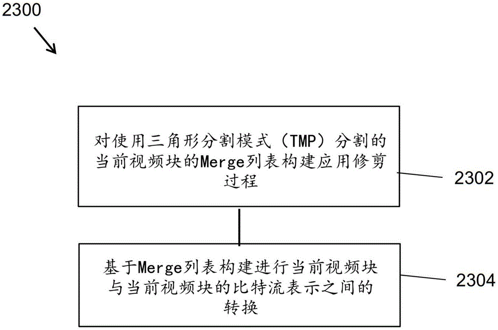
Fig. 23 is a flowchart of an example of a video processing method.
Fig. 24 shows an example of 3 CUs under a shared Merge region (SMR, having a size of 16x 4) and SMR.
Fig. 25 is a block diagram of an exemplary video processing system in which the disclosed technology may be implemented.
FIG. 26 shows an example of an optical flow trace.
FIGS. 27A-27B illustrate examples of BIOs without block extensions.
Fig. 28 shows an example of interpolated samples used in BIO.
Fig. 29 shows an example of the subblock MV VSB and the pixel Δ v (i, j).
FIG. 30 shows an example of the proposal in JFET-P0068 and TPM design in VTM-6.0.
Fig. 31 shows GEO partition boundary description.
Fig. 32 shows an example of angular quantization of the geometric Merge mode.
FIG. 33 shows signaling for Merge mode in VTM-5.0.
Fig. 34 shows an example of a signaling method of the proposed Merge mode.
FIG. 35 is a block diagram of an exemplary video processing system in which the disclosed technology may be implemented.
Fig. 36 is a block diagram illustrating an exemplary video codec system.
Fig. 37 is a block diagram illustrating an encoder in accordance with some embodiments of the present disclosure.
Fig. 38 is a block diagram illustrating a decoder according to some embodiments of the present disclosure.
Fig. 39 is a flow chart of an example of a visual media processing method.
Fig. 40 is a flow chart of an example of a visual media processing method.
Fig. 41 is a flow chart of an example of a visual media processing method.
Detailed Description
This document provides various techniques that may be used by a decoder of an image or video bitstream to improve the quality of compressed or encoded digital video or images. For brevity, the term "video" is used herein to include both a sequence of pictures (conventionally referred to as a video) and a separate image. In addition, the video encoder may also implement these techniques during the course of encoding in order to reconstruct the decoded frames for further encoding.
Section headings are used in this document for ease of understanding and do not limit embodiments and techniques to the corresponding sections. Thus, embodiments from one section may be combined with embodiments from other sections.
1. Brief summary
This document relates to video coding and decoding techniques. In particular, it relates to Merge codec including triangle prediction modes. It can be applied to existing video codec standards, such as HEVC, or to standards to be finalized (multifunctional video codec). It can also be applied to future video codec standards or video codecs.
2. Initial discussion
The video codec standard has evolved largely through the development of the well-known ITU-T and ISO/IEC standards. ITU-T produces H.261 and H.263, ISO/IEC produces MPEG-1 and MPEG-4 vision, and both organizations jointly produce the H.262/MPEG-2 video and the H.264/MPEG-4 Advanced Video Codec (AVC) and H.265/HEVC standards. Since h.262, the video codec standard is based on a hybrid video codec structure, in which temporal prediction plus transform coding is employed. In order to explore future video codec technologies beyond HEVC, the joint video exploration group (jfet) was jointly established by VCEG and MPEG in 2015. Since then, many new methods have been adopted by jfet and put into the reference software named Joint Exploration Model (JEM). In month 4 of 2018, a joint video experts group (jfet) between VCEG (Q6/16) and ISO/IEC JTC1 SC29/WG11(MPEG) was created to study the VVC standard with a 50% bit rate reduction compared to HEVC.
The latest version of the VVC draft, i.e. the multifunctional video codec (draft 5), can be found in: http:// phenix. it-supplaris. eu/JVET/doc _ end _ user/documents/14_ Geneva/wg11/JVET-N1001-v7.zip
The latest reference software for VVCs (named VTM) can be found in: https: v/cgit. hhi. fraunhofer. de/jvet/VVCSOFTWARE _ VTM/tags/VTM-5.0
Inter prediction in 2.1 HEVC/H.265
For a Coding Unit (CU) of inter coding, it can be coded with one Prediction Unit (PU), 2 PUs, according to the partition mode. Each inter-predicted PU has motion parameters of one or two reference picture lists. The motion parameters include a motion vector and a reference picture index. The use of one of the two reference picture lists can also be signaled using inter _ pred _ idc. Motion vectors can be explicitly coded as deltas relative to the predictor.
When a CU is coded with skip mode, one PU is associated with the CU and there are no significant residual coefficients, no coded motion vector delta or reference picture index. A Merge mode is specified, by which the motion parameters of the current PU, including spatial and temporal candidates, are obtained from the neighboring PU. The Merge mode may be applied to any inter-prediction PU, not just the skip mode. An alternative to the Merge mode is the explicit sending of motion parameters, where the motion vector (more precisely, the Motion Vector Difference (MVD) compared to the motion vector predictor), the corresponding reference picture index and reference picture list usage of each reference picture list are explicitly signaled per PU. Such a mode is referred to in this disclosure as Advanced Motion Vector Prediction (AMVP).
When the signaling indicates that one of the two reference picture lists is to be used, the PU is generated from one block of samples. This is called 'unidirectional prediction'. Unidirectional prediction is available for both P-slices and B-slices.
When the signaling indicates that both reference picture lists are to be used, the PU is generated from two blocks of samples. This is called 'bi-prediction'. Bi-directional prediction is only available for B slices.
The following text provides details regarding the inter prediction modes specified in HEVC. The description will start with the Merge mode.
2.1.1 reference Picture List
In HEVC, the term inter prediction is used to refer to a prediction derived from a reference picture instead of a data element (e.g., a sample value or a motion vector) of a currently decoded picture. As in h.264/AVC, pictures can be predicted from multiple reference pictures. Reference pictures used for inter prediction are organized into one or more reference picture lists. The reference index identifies which of the reference pictures in the list should be used to create the prediction signaling notification.
A single reference picture list (list 0) is used for P slices and two reference picture lists (list 0 and list 1) are used for B slices. It should be noted that the reference pictures contained in the list 0/1 may be pictures from the past and future in terms of capture/display order.
2.1.2 Merge mode
2.1.2.1 derivation of candidates for Merge mode
When the PU is predicted using the Merge mode, the index pointing to an entry in the Merge candidate list is parsed from the bitstream and used to retrieve motion information. The construction of this list is specified in the HEVC standard and can be summarized according to the sequence of the following steps:
● step 1: initial candidate derivation
Step 1.1: spatial domain candidate derivation
Step 1.2: redundancy check of spatial domain candidates
Step 1.3: time domain candidate derivation
● step 2: additional candidate insertions
Step 2.1: creation of bi-directional prediction candidates
Step 2.2: insertion of zero motion candidates
These steps are also schematically depicted in fig. 1. For spatial domain Merge candidate derivation, a maximum of four Merge candidates are selected among the candidates located in five different positions. For time-domain Merge candidate derivation, at most one Merge candidate is selected among the two candidates. Since a constant number of candidates per PU is assumed at the decoder, additional candidates are generated when the number of candidates obtained from step 1 does not reach the maximum number of Merge candidates (maxnummerge candidates) signaled in the slice header. Since the number of candidates is constant, the index of the best Merge candidate is encoded using truncated unary binarization (TU). If the size of the CU is equal to 8, all PUs of the current CU share a single Merge candidate list, which is the same as the Merge candidate list of the 2N × 2N prediction unit.
In the following, the operations associated with the foregoing steps are detailed.
2.1.2.2 spatial domain candidate derivation
In the derivation of spatial domain Merge candidates, a maximum of four Merge candidates are selected among the candidates located in the positions illustrated in FIG. 2. The order of derivation is A1、B1、B0、A0And B2. Only when in position A1、B1、B0、A0Is not available (e.g., because it belongs to another slice or slice) or is intra-coded, but considers location B2. In position A1After adding the candidates, the addition of the remaining candidates is subjected to a redundancy check, which ensures that candidates with the same motion information are excluded from the list, so that the coding efficiency is improved. To reduce computational complexity, not all possible candidate pairs are considered for the mentioned redundancy check. Instead, only pairs linked with arrows in fig. 3 are considered and candidates are added to the list only if the corresponding candidates for redundancy check do not have the same motion information. Another source of duplicate motion information is the "second PU" associated with a partition other than Nx 2N. As an example, fig. 4 shows the second PU for the N × 2N and 2N × N cases, respectively. When the current PU is partitioned into Nx2N, the list construction does not take into account location A1Is selected. In fact, adding this candidate will result in two prediction units having the same motion information, which is redundant for having only one PU in the coded unit. Similarly, when the current PU is divided into 2 NxN, position B is not considered1。
2.1.2.3 time-domain candidate derivation
In this step, only one candidate is added to the list. In particular, in deriving the temporal Merge candidate, a scaling motion vector is derived based on a co-located PU in a co-located picture. The scaled motion vectors for the temporal domain Merge candidates are obtained as indicated by the dashed lines in FIG. 5, scaled from the motion vectors of the co-located PUs using the POC distances (tb and td), where tb is defined as the POC difference between the reference picture of the current picture and the current picture, and td is defined as the POC difference between the reference picture of the co-located picture and the co-located picture. The reference picture index of the temporal domain Merge candidate is set equal to zero. A practical implementation of the scaling process is described in HEVC specification [1 ]. For B slices, two motion vectors are obtained and combined for bi-prediction target candidates, one for reference picture list0 and the other for reference picture list 1.
2.1.2.4 Co-located Picture and Co-located PU
When TMVP is enabled (i.e., slice _ temporal _ mvp _ enabled _ flag is equal to 1), the variable ColPic representing a co-located picture is derived as follows:
-if the current slice is a B slice and the signaled collocated _ from _ l0_ flag is equal to 0, ColPic is set equal to RefPicList1[ collocated _ ref _ idx ].
Otherwise (slice _ type equal to B and collocated _ from _ l0_ flag equal to 1, or slice _ type equal to P), ColPic is set equal to RefPicList0[ collocated _ ref _ idx ].
Where collocated _ ref _ idx and collocated _ from _ l0_ flag are two syntax elements that may be signaled in the slice header.
In co-located PU (Y) belonging to the reference frame, in candidate C0And C1The location of the time domain candidate is selected as shown in fig. 6. If at position C0Where the PU is unavailable, intra-coded or outside the current coding tree unit (CTU, also called LCU, maximum coding unit) row, then position C is used1. Otherwise, position C is used in deriving the time domain Merge candidate0。
The relevant syntax elements are described as follows:
7.3.6.1 general stripe header grammar


2.1.2.5 derivation of MV of TMVP candidates
More specifically, the following steps are performed in order to derive TMVP candidates:
1) setting the reference picture list X to 0, the target reference picture is the reference picture in the list X with an index equal to 0 (i.e., curr _ ref). The derivation process of the co-located motion vector is invoked to get the MV pointing to list X of curr _ ref.
2) If the current slice is a B slice, then the reference picture list X is set to 1, and the target reference picture is the reference picture with an index equal to 0 in list X (i.e., curr _ ref). The derivation process of the co-located motion vectors is invoked to get the MV pointing to list X of curr _ ref.
The derivation of co-located motion vectors is described in the next subsection 2.1.2.5.1.
2.1.2.5.1 derivation of co-located motion vectors
For co-located blocks, they may be intra or inter coded using uni-directional prediction or bi-directional prediction. If it is intra-coded, the TMVP candidate is set as unavailable.
If it is a unidirectional prediction from list a, the motion vector of list a is scaled to the target reference picture list X.
If it is bi-predictive and the target reference picture list is X, the motion vector of list a is scaled to the target reference picture list X, and a is determined according to the following rule:
-a is set equal to X if no reference picture has a larger POC value compared to the current picture.
Otherwise, a is set equal to collocated _ from _ l0_ flag.
The related working draft in JCTVC-W1005-v4 is described as follows:
8.5.3.2.9 derivation of co-located motion vectors
The inputs to this process are:
a variable currPb specifying the current prediction block,
a variable colPb specifying a co-located prediction block within a co-located picture slice specified by ColPic,
-a luma position (xColPb, yColPb) specifying a left top luma sample of the co-located luma prediction block specified by ColPb relative to a left top luma sample of the co-located picture specified by ColPic,
-a reference index refIdxLX, wherein X is 0 or 1.
The outputs of this process are:
-a motion vector prediction mvLXClE,
the availability flag availableFlagLXCol.
The variable currPic specifies the current picture.
Arrays predFlagL0Col [ x ] [ y ], mvL0Col [ x ] [ y ], and refIdxL0Col [ x ] [ y ] are respectively set equal to predFlagL0[ x ] [ y ], MvL0[ x ] [ y ], and RefIdxL0[ x ] [ y ] of the co-located picture specified by ColPic, and arrays predFlagL1Col [ x ] [ y ], mvL1Col [ x ] [ y ], and refIdxL1Col [ x ] [ y ] are respectively set equal to predFlagL1[ x ] [ y ], MvL1[ x ] [ y ], and RefxL 1[ x ] [ Idy ] of the co-located picture specified by ColPic.
The variables mvLXCol and availableFlagLXCol are derived as follows:
-if colPb is coded in intra prediction mode, both components of mvLXCol are set equal to 0, and availableFlagLXCol is set equal to 0.
Otherwise, the motion vector mvCol, the reference index refIdxCol and the reference list identifier listCol are derived as follows:
-if predFlagL0Col [ xClPb ] [ yColPb ] is equal to 0, then mvCol, refIdxCol and listCol are set equal to mvL1Col [ xClPb ] [ yColPb ], refIdxL1Col [ xClPb ] [ yColPb ] and L1, respectively.
Otherwise, if predFlagL0Col [ xClPb ] [ yColPb ] equals 1 and predFlagL1Col [ xClPb ] [ yColPb ] equals 0, then mvCol, refIdxCol, and listCol are set equal to mvL0Col [ xClPb ] [ yColPb ], refIdxL0Col [ xClb ] [ yColPb ] and L0, respectively.
Else (predFlagL0Col [ xClPb ] [ yColPb ] equal to 1 and predFlagL1Col [ xClPb ] [ yColPb ] equal to 1), the following allocation is made:
-if NoBackwardPredFlag is equal to 1, then mvCol, refIdxCol and listCol are set equal to mvLXClC [ xClPb ] [ yColPb ], refIdxLXClC [ xClPb ] [ yColPb ] and LX, respectively.
-otherwise, mvCol, refIdxCol and listCol are set equal to mvLNCol [ xClPb ] [ yColPb ], refIdxLNCol [ xClPb ] [ yColPb ], respectively
And LN, and N is the value of collocated _ from _ l0_ flag.
And mvLXCol and availableFlagLXCol are derived as follows:
-if longtermrfpic (currPic, currPb, refIdxLX, LX) is not equal to longtermrfpic (ColPic, colPb, refIdxCol, listCol), both components of mvLXCol are set equal to 0 and availableFlagLXCol is set equal to 0.
-otherwise, the variable availableFlagLXCol is set equal to 1, refPicListCol [ refIdxCol ] is set to the picture with reference index refIdxCol in the reference picture list listCol of the slice containing the prediction block colPb in the co-located picture specified by ColPic, and the following applies:
colPocDiff=DiffPicOrderCnt(ColPic,refPicListCol[refIdxCol]) (2-1)
currPocDiff=DiffPicOrderCnt(currPic,RefPicListX[refIdxLX]) (2-2)
-if RefPicListX [ refIdxLX ] is a long term reference picture, or colPocDiff is equal to currPocDiff, mvLXCol is derived as follows:
mvLXCol=mvCol (2-3)
otherwise, mvLXCol is derived as a scaled version of the motion vector mvCol as follows:
tx=(16384+(Abs(td)>>1))/td (2-4)
distScaleFactor=Clip3(-4096,4095,(tb*tx+32)>>6) (2-5)
mvLXCol=Clip3(-32768,32767,Sign(distScaleFactor*mvCol)*
((Abs(distScaleFactor*mvCol)+127)>>8)) (2-6)
where td and tb are derived as follows:
td=Clip3(-128,127,colPocDiff) (2-7)
tb=Clip3(-128,127,currPocDiff) (2-8)
the definition of NoBackwardPredFlag is:
the variable NoBackwardPredFlag is derived as follows:
-nobackward predflag is set equal to 1 if DiffPicOrderCnt (aPic, CurrPic) is less than or equal to 0 for each picture aPic in RefPicList0 or RefPicList1 of the current slice.
Else NoBackwardPredFlag is set equal to 0.
2.1.2.6 additional candidate insertions
In addition to spatial and temporal Merge candidates, there are two additional types of Merge candidates: the bidirectional prediction Merge candidate and the zero Merge candidate are combined. The combined bidirectional prediction Merge candidate is generated by using spatial and temporal Merge candidates. The combined bi-directional prediction Merge candidate is used for B slices only. The combined bi-prediction candidate is generated by combining the first reference picture list motion parameters of the initial candidate with the second reference picture list motion parameters of the other candidate. If these two tuples (tuple) provide different motion hypotheses, they will form new bi-directional prediction candidates. As an example, fig. 7 shows the case when two candidates (with mvL0 and refIdxL0, or mvL1 and refIdxL1) in the original list (left) are used to create the combined bi-predictive Merge candidate that is added to the final list (right). There are many rules regarding combinations that are considered to generate these additional Merge candidates, defined in [1 ].
Zero motion candidates are inserted to fill the remaining entries in the Merge candidate list and thus reach the maxnummerge capacity. These candidates have zero spatial shift and reference picture indices that start at zero and increase each time a new zero motion candidate is added to the list. Finally, no redundancy check is performed on these candidates.
2.1.3 AMVP
AMVP uses the spatial-temporal association of motion vectors with neighboring PUs, which is used for explicit transmission of motion parameters. For each reference picture list, a motion vector candidate list is constructed by: the availability of contiguous PU locations in the left and top time domains is first checked, redundant candidates are removed, and zero vectors are added to make the candidate list a constant length. The encoder may then select the best predictor from the candidate list and transmit a corresponding index indicating the selected candidate. Similar to the Merge index signaling, the index of the best motion vector candidate is coded using a truncated unary. The maximum value of the encoding in this case is 2 (see fig. 8). In the following sections, details regarding the derivation process of motion vector prediction candidates are provided.
2.1.3.1 derivation of AMVP candidates
Fig. 8 summarizes the derivation of motion vector prediction candidates.
In motion vector prediction, two types of motion vector candidates are considered: spatial motion vector candidates and temporal motion vector candidates. For spatial motion vector candidate derivation, two motion vector candidates are finally derived based on the motion vectors of each PU located in five different positions as shown in fig. 2.
For temporal motion vector candidate derivation, one motion vector candidate is selected from two candidates, which are derived based on two different co-located positions. After generating the first list of spatio-temporal candidates, duplicate motion vector candidates in the list are removed. If the number of potential candidates is greater than two, then motion vector candidates with reference picture indices greater than 1 within the associated reference picture list are removed from the list. If the number of spatio-temporal motion vector candidates is less than two, additional zero motion vector candidates are added to the list.
2.1.3.2 spatial motion vector candidates
In the derivation of spatial motion vector candidates, a maximum of two candidates are considered among five potential candidates derived from PUs located at the positions shown in fig. 2, which are the same as those of the motion Merge. The order of derivation on the left side of the current PU is defined as A0、A1And scaled A0Zoom of A1. Of the upper side of the current PUThe order of derivation is defined as B0、B1、B2Zoomed B0Zoomed B1Zoomed B2. There are thus four cases for each side that can be used as motion vector candidates, two of which do not require the use of spatial scaling and two of which use spatial scaling. Four different cases are summarized below.
● No spatial domain scaling
- (1) same reference picture list, and same reference picture index (same POC)
- (2) different reference picture lists, but the same reference picture (same POC)
● spatial domain scaling
- (3) same reference picture list, but different reference pictures (different POCs)
- (4) different reference picture lists, and different reference pictures (different POCs)
The case of no spatial scaling is checked first, followed by a check for spatial scaling. Spatial scaling is considered when POC is different between reference pictures of neighboring PUs and reference pictures of the current PU, regardless of the reference picture list. If all PUs of the left candidate are not available or intra coded, scaling of the above motion vectors is allowed to facilitate parallel derivation of left and above MV candidates. Otherwise, spatial scaling is not allowed for the above motion vectors.
In the spatial scaling process, the motion vectors of neighboring PUs are scaled in a similar manner as the temporal scaling, as shown in fig. 9. The main difference is that the reference picture list and index of the current PU are given as input; the actual scaling procedure is the same as that of the time domain scaling.
2.1.3.3 temporal motion vector candidates
Except for the reference picture index derivation, the overall process of deriving temporal domain Merge candidates is the same as the process of deriving spatial motion vector candidates (see fig. 6). The reference picture index is signaled to the decoder.
2.2 inter-frame prediction method in VVC
Several new codec tools exist for inter-prediction improvement, such as adaptive motion vector difference resolution (AMVR) for signaling MVD, merge with motion vector difference (mmvd), Triangle Prediction Mode (TPM), combined intra-frame inter-prediction (CIIP), advanced TMVP (ATMVP, also known as SbTMVP), affine prediction mode, generalized bi-directional prediction (GBI), decoder-side motion vector refinement (DMVR), and bi-directional optical flow (BIO, also known as BDOF).
There are three different Merge list building processes supported in VVC:
1) subblock Merge candidate list: which contains ATMVP and affine Merge candidates. A Merge list building process is shared by two affine modes and an ATMVP mode. Here, ATMVP and affine Merge candidates may be added in order. The sub-block Merge list size is signaled in the slice header and has a maximum value of 5.
2) Conventional Merge List: for inter-frame codec blocks, a Merge list building process is shared. Here, the spatial/temporal Merge candidate, the HMVP, the pair Merge candidate, and the zero motion candidate may be inserted in order. The conventional Merge list size is signaled in the slice header and is a maximum of 6. MMVD, TPM and CIIP rely on the conventional Merge list.
3) List of IBCMerges: in a similar manner to the conventional Merge list.
Similarly, there are three lists of AMVP supported in VVC:
1) affine AMVP candidate list
2) Conventional AMVP candidate list
3) IBC AMVP candidate list: due to the adoption of JFET-N0843 and IBC Merge
List identity construction process
Coding and decoding block structure in 2.2.1 VVC
In VVC, a quadtree/binary tree/ternary tree (QT/BT/TT) structure is employed to divide a picture into square or rectangular blocks.
In addition to QT/BT/TT, split trees (also called dual coding trees) are also employed for I frames in VVC. In the case of a split tree, the codec block structure is signaled separately for the luma and chroma components.
Furthermore, a CU is set equal to PU and TU, except for blocks coded with several particular coding methods (such as intra sub-partition prediction, where PU is equal to TU but less than CU; and sub-block transform of inter coded blocks, where PU is equal to CU but TU is less than PU).
2.2.2 affine prediction mode
In HEVC, the translational motion model is only applied to Motion Compensated Prediction (MCP). While in the real world there are many kinds of movements such as zoom in/out, rotation, perspective movement and other non-conventional movements. In VVC, a simplified affine transform motion compensated prediction is applied with a 4-parameter affine model and a 6-parameter affine model. As shown in fig. 10, the affine motion field of the block is described by two Control Point Motion Vectors (CPMV) for the 4-parameter affine model and by 3 CPMV for the 6-parameter affine model.
The Motion Vector Field (MVF) of a block is described by the following equation, by equation (1) in the case of a 4-parameter affine model (where 4 parameters are defined as variables a, b, e, and f), and by equation (2) in the case of a 6-parameter affine model (where 4 parameters are defined as variables a, b, c, d, e, and f), respectively:


wherein (mv)h 0,mvh 0) Is the motion vector of the control point of the left corner, and (mv)h 1,mvh 1) Is the motion vector of the right corner control point, and (mv)h 2,mvh 2) Is the motion vector of the bottom left corner control point, all three motion vectors are called Control Point Motion Vectors (CPMV), (x, y) represent the coordinates of the representative point relative to the top left sample point in the current block, and (mv)h(x,y),mvv(x, y)) is a motion vector derived for a sample located at (x, y). The CP motion vector may be signaled (e.g., affine)AMVP mode) or derived in real-time (as in affine Merge mode). W and h are the width and height of the current block. In practice, division is achieved by right-shifting and rounding operations. In the VTM, a representative point is defined as the center position of the subblock, for example, when the coordinates of the top left corner of the subblock with respect to the top left sampling point within the current block are (xs, ys), the coordinates of the representative point are defined as (xs +2, ys + 2). For each sub-block (i.e., 4x4 in the VTM), the representative point is used to derive the motion vector for the entire sub-block.
To further simplify motion compensated prediction, sub-block based affine transform prediction is applied. To derive the motion vector of each M × N (in the current VVC, M and N are both set to 4) subblock, the motion vector of the center sample point of each subblock as shown in fig. 11 is calculated according to equations (1) and (2), and rounded to 1/16 fractional accuracy. Motion compensated interpolation filtering of 1/16 pixels is then used to generate a prediction for each sub-block with the derived motion vector. The interpolation filtering of 1/16 pixels is introduced by the affine mode.
After MCP, the high accuracy motion vector of each sub-block is rounded and saved to the same accuracy as the normal motion vector.
2.2.3 Merge of entire Block
2.2.3.1 Merge list construction for translating conventional Merge mode
2.2.3.1.1 History-based motion vector prediction (HMVP)
Unlike the Merge list design, in VVC, a history-based motion vector prediction (HMVP) method is employed.
In HMVP, the motion information of the previous codec is stored. The motion information of the previously coded block is defined as an HMVP candidate. A number of HMVP candidates are stored in a table, named HMVP table, and this table is maintained in real-time during the encoding/decoding process. When starting to encode/decode a new slice/LCU row/slice, the HMVP table is emptied. Whenever there is an inter codec block and non-subblock, non-TPM mode, the associated motion information is added to the last entry of the table as a new HMVP candidate. The overall codec flow is depicted in fig. 12.
2.2.3.1.2. Conventional Merge List building Process
The construction of a conventional Merge list (for translational motion) can be summarized according to the following sequence of steps:
● step 1: deriving spatial domain candidates
● step 2: inserting HMVP candidates
● step 3: interpolating pairwise mean candidates
● step 4: default motion candidate
The HMVP candidates may be used in both the AMVP and Merge candidate list construction processes. FIG. 13 depicts a modified Merge candidate list building process (highlighted in the gray box). When the Merge candidate list is not full after the TMVP candidate insertion, the HMVP candidates stored in the HMVP table may be used to populate in the Merge candidate list. The HMVP candidates in the table are inserted in descending order of index, considering that a block usually has a higher association with the nearest neighboring block in terms of motion information. The last entry in the table is added to the list first and the first entry is added last. Similarly, redundancy removal is applied on the HMVP candidates. Once the total number of available Merge candidates reaches the maximum number of Merge candidates allowed to be signaled, the Merge candidate list construction process terminates.
Note that all spatial/temporal/HMVP candidates should be coded in non-IBC mode. Otherwise, it is not allowed to be added to the regular Merge candidate list.
The HMVP table contains up to 5 regular motion candidates, and each of them is unique.
2.2.3.1.2.1 pruning procedure
A candidate is added to the list only if the corresponding candidate for redundancy check does not have the same motion information. Such a comparison process is called a pruning process.
The pruning process among the spatial candidates depends on the use of the TPM of the current block.
When the current block is coded without TPM mode (e.g., regular Merge, MMVD, CIIP), the HEVC pruning process (i.e., five pruning) is employed for the null domain Merge candidate.
2.2.4 Triangle Prediction Mode (TPM)
In VVC, a triangulation mode is supported for inter prediction. The triangulation mode is applied only to CUs that are 8x8 or larger and are coded in the Merge mode but not in the MMVD or CIIP mode. For CUs that meet these conditions, a CU level flag is signaled to indicate whether or not to apply triangulation mode.
When this mode is used, the CU is uniformly divided into two triangular partitions, using either diagonal or anti-diagonal partitioning, as shown in fig. 14. Each triangulation in a CU is predicted inter-frame using its own motion; only uni-directional prediction is allowed for each partition, i.e. each partition has one motion vector and one reference index. The uni-directional prediction motion constraint is applied to ensure that only two motion compensated predictions are needed per CU, as in conventional bi-directional prediction.
If the CU level flag indicates that the current CU is coded using the triangulation mode, a flag indicating the direction of triangulation (diagonal or anti-diagonal) and two large indices (one for each split) are further signaled. After each of the triangulation is predicted, sample values along diagonal or anti-diagonal edges are adjusted using a blending process with adaptive weights. This is a prediction signaling of the entire CU and the transform and quantization process will be applied to the entire CU as in other prediction modes. Finally, the motion field of the CU predicted using the triangulation mode is stored in a 4 × 4 unit.
The conventional Merge candidate list is repeated for the triangulation Merge prediction without additional motion vector pruning. For each Merge candidate in the regular Merge candidate list, one and only one of its L0 or L1 motion vectors is used for the triangle prediction. Further, the order of selecting L0 for the L1 motion vector is based on its Merge index parity. In the case of this scheme, the regular Merge list can be used directly.
2.2.4.1 Merge list building process of TPM
Basically, the conventional Merge list building process is applied as proposed in JFET-N0340. However, some modifications were added.
In particular, the following applies:
1) how the pruning process is done depends on the use of the TPM of the current block
-if the current block is not TPM-coded, invoke HEVC 5 pruning applied to spatial Merge candidates
Otherwise (if the current block is TPM-coded), full pruning is applied when a new spatial domain Merge candidate is added. That is, B1 compared to a 1; b0 compared to a1 and B1; a0 compared to a1, B1, and B0; b2 was compared to a1, B1, a0, and B0.
2) The condition of whether to check the motion information from B2 depends on the use of TPM on the current block
-if the current block is not TPM-coded, access and check B2 only if there are less than 4 spatial Merge candidates before checking B2.
Else (if the current block is TPM-coded), B2 is always accessed and checked, no matter how many spatial domain Merge candidates are available before adding B2.
2.2.4.2 adaptive weighting process
After predicting each triangle prediction unit, an adaptive weighting process is applied to the diagonal edges between the two triangle prediction units to derive the final prediction of the entire CU. Two sets of weighting factors are defined as follows:
● weighting factor group 1: {7/8, 6/8, 4/8, 2/8, 1/8} and {7/8, 4/8, 1/8}
Are used for luminance and chrominance samples, respectively;
● group 2 weighting factors: {7/8, 6/8, 5/8, 4/8, 3/8, 2/8, 1/8} and {6/8, 4/8, 2/8} are used for luminance and chrominance samples, respectively.
The weighting factor set is selected based on a comparison of the motion vectors of the two triangle prediction units. The 2 nd weighting factor set is used when any of the following conditions is true:
-the reference pictures of the two triangular prediction units are different from each other
-the absolute value of the difference of the horizontal values of the two motion vectors is larger than 16 pixels.
-the absolute value of the difference of the vertical values of the two motion vectors is larger than 16 pixels.
Otherwise, the 1 st weighting factor set is used. An example is shown in fig. 15.
2.2.4.3 motion vector storage
The motion vectors of the triangle prediction units (Mv1 and Mv2 in fig. 16) are stored in a 4 × 4 mesh. For each 4x4 mesh, either uni-directional predicted or bi-directional predicted motion vectors are stored, depending on the position of the 4x4 mesh in the CU. As shown in fig. 16, the uni-directional predictive motion vector (Mv1 or Mv2) is stored for the 4 × 4 mesh located in a non-weighted region (i.e., not located at diagonal edges). On the other hand, the bidirectional predictive motion vector is stored for the 4 × 4 mesh located in the weighting region. Bi-predictive motion vectors are derived from Mv1 and Mv2 according to the following rules:
1) in the case of Mv1 and Mv2 with motion vectors from different directions (L0 or L1), Mv1 and Mv2 are simply combined to form bi-predictive motion vectors.
2) In the case where both Mv1 and Mv2 are from the same L0 (or L1) direction,
mv2 is scaled to a picture in the L1 (or L0) reference picture list if the reference picture of Mv2 is the same as the picture. The Mv1 and scaled Mv2 are combined to form a bi-predictive motion vector.
If the reference picture of Mv1 is the same as the picture in the L1 (or L0) reference picture list, Mv1 is scaled to that picture. The scaled Mv1 and Mv2 are combined to form a bi-predictive motion vector.
Else, store only Mv1 for the weighted region.
2.2.4.4 Merge mode grammar table, semantic and decoding process
7.3.5.1 general stripe header syntax


7.3.7.5 codec Unit syntax


7.3.7.7 Merge data syntax


7.4.6.1 general Bandwidth header semantics
six minus max num Merge cand specifies 6 minus the maximum number of Merge Motion Vector Prediction (MVP) candidates supported in a slice. The maximum number of Merge MVP candidates, MaxUMMergeCand, is derived as follows:
MaxNumMergeCand=6-six_minus_max_num_merge_cand (7-57)
the value of maxnummergeecd should be in the range of 1 to 6 inclusive.
five _ minus _ max _ num _ sub _ Merge _ cand specifies 5 minus the maximum number of subblock-based Merge Motion Vector Prediction (MVP) candidates supported in the slice. When five _ minus _ max _ num _ sublock _ merge _ cand is not present, it is inferred to be equal to 5-sps _ sbtmvp _ enabled _ flag. Based on the maximum number of Merge MVP candidates for a sub-block, MaxumSubblockMergeCand is derived as follows:
MaxNumSubblockMergeCand=5-five_minus_max_num_subblock_merge_cand (7-58)
the value of maxnumsubablockmergeand should be in the range of 0 to 5 inclusive.
7.4.8.5 codec unit semantics
pred _ mode _ flag equal to 0 specifies that the current codec unit is codec in inter prediction mode. pred _ mode _ flag equal to 1 specifies that the current codec unit is codec in intra prediction mode.
When pred _ mode _ flag is not present, it is inferred as follows:
-pred _ mode _ flag is inferred to be equal to 1 if cbWidth is equal to 4 and cbHeight is equal to 4.
-otherwise, pred _ mode _ flag is inferred to be equal to 1 when decoding I slices and 0 when decoding P or B slices, respectively.
For x x0., x0+ cbWidth-1 and y y0., y0+ cbHeight-1, the variable CuPredMode [ x ] [ y ] is derived as follows:
if pred _ MODE _ flag is equal to 0, CuPredMode [ x ] [ y ] is set equal to MODE _ INTER.
Else (pred _ MODE _ flag equal to 1), CuPredMode [ x ] [ y ] is set equal to MODE _ INTRA.
pred _ mode _ IBC _ flag equal to 1 specifies that the current codec unit is codec in IBC prediction mode. pred _ mode _ IBC _ flag equal to 0 specifies that the current codec unit is not codec in IBC prediction mode.
When pred _ mode _ ibc _ flag is not present, it is inferred as follows:
if cu _ skip _ flag [ x0] [ y0] is equal to 1, cbWidth is equal to 4, and cbHeight is equal to 4, pred _ mode _ ibc _ flag is inferred to be equal to 1.
Otherwise, if cbWidth and cbHeight both equal 128, then pred _ mode _ ibc _ flag is inferred to be equal to 0.
-else, pred _ mode _ ibc _ flag is inferred to be equal to the value of sps _ ibc _ enabled _ flag when decoding I slices and 0 when decoding P or B slices, respectively.
When pred _ MODE _ IBC _ flag is equal to 1, the variable CuPredMode [ x ] [ y ] is set equal to MODE _ IBC for x x0., x0+ cbWidth-1 and y y0., y0+ cbHeight-1.
general _ merge _ flag x 0y 0 specifies whether the inter prediction parameters of the current codec unit are inferred from the contiguous inter prediction partitions. The array indices x0, y0 specify the position of the top left luma sample of the considered codec block relative to the top left luma sample of the picture (x0, y 0).
When general _ merge _ flag [ x0] [ y0] is absent, it is inferred as follows:
-general _ merge _ flag [ x0] [ y0] is inferred to be equal to 1 if cu _ skip _ flag [ x0] [ y0] is equal to 1.
Otherwise, general _ merge _ flag [ x0] [ y0] is inferred to be equal to 0.
mvp _ l0_ flag [ x0] [ y0] specifies the motion vector predictor index of list0, x0, y0 specify the position of the top left luma sample of the considered codec block relative to the top left luma sample of the picture (x0, y 0).
When mvp _ l0_ flag [ x0] [ y0] is not present, it is inferred to be equal to 0.
mvp _ l1_ flag [ x0] [ y0] has the same semantic as mvp _ l0_ flag, where l0 and list0 are replaced by l1 and list1, respectively.
inter _ pred _ idc x 0y 0 specifies whether list0, list1 or bi-prediction is used for the current codec unit, according to tables 7-10. The array indices x0, y0 specify the position of the top left luma sample of the considered codec block relative to the top left luma sample of the picture (x0, y 0).
TABLE 7-10 name Association for inter prediction modes

When inter _ PRED _ idc x 0y 0 is not present, it is inferred to be equal to PRED _ L0.
7.4.8.7 Merge data semantics
regular _ Merge _ flag x 0y 0 equals 1 designation, and the regular Merge mode is used to generate inter prediction parameters for the current codec unit. The array indices x0, y0 specify the position of the top left luma sample of the considered codec block relative to the top left luma sample of the picture (x0, y 0).
When regular _ merge _ flag [ x0] [ y0] is not present, it is inferred as follows:
-regular _ merge _ flag [ x0] [ y0] is inferred to be equal to 1 if all of the following conditions are true:
-sps _ mmvd _ enabled _ flag is equal to 0.
-general _ merge _ flag [ x0] [ y0] equal to 1.
-cbWidth cbHeight equal to 32.
Otherwise, regular _ merge _ flag [ x0] [ y0] is inferred to be equal to 0.
mmvd _ Merge _ flag [ x0] [ y0] is equal to 1 designation, Merge mode with motion vector difference is used to generate inter prediction parameters for the current codec unit. The array indices x0, y0 specify the position of the top left luma sample of the considered codec block relative to the top left luma sample of the picture (x0, y 0).
When mmvd _ merge _ flag [ x0] [ y0] is not present, it is inferred as follows:
-mmvd _ merge _ flag [ x0] [ y0] is inferred to be equal to 1 if all of the following conditions are true:
-sps _ mmvd _ enabled _ flag is equal to 1.
-general _ merge _ flag [ x0] [ y0] equal to 1.
-cbWidth cbHeight equal to 32.
-regular _ merge _ flag x 0y 0 equal to 0.
Otherwise, mmvd _ merge _ flag [ x0] [ y0] is inferred to be equal to 0.
The mmvd _ cand _ flag [ x0] [ y0] specifies whether the first (0) or second (1) candidate in the Merge candidate list is used with the motion vector disparity derived from mmvd _ distance _ idx [ x0] [ y0] and mmvd _ direction _ idx [ x0] [ y0 ]. The array indices x0, y0 specify the position of the top left luminance sample of the considered codec block relative to the top left luminance sample of the picture (x0, y 0).
When mmvd _ cand _ flag [ x0] [ y0] is not present, it is inferred to be equal to 0.
mmvd _ distance _ idx [ x0] [ y0] specifies the index used to derive MmvdDistance [ x0] [ y0] as specified in tables 7-12. The array indices x0, y0 specify the position of the top left luma sample of the considered codec block relative to the top left luma sample of the picture (x0, y 0).
Tables 7-12-Specifications for MmvdDistance [ x0] [ y0] based on mmvd _ distance _ idx [ x0] [ y0]

mmvd _ direction _ idx [ x0] [ y0] specifies the index used to derive MmvdSign [ x0] [ y0] as specified in tables 7-13. The array indices x0, y0 specify the position of the top left luma sample of the considered codec block relative to the top left luma sample of the picture (x0, y 0).
TABLE 7-13-MmvdSign [ x0] [ y0] Specification based on mmvd _ direction _ idx [ x0] [ y0]

The two components of Merge plus the MVD offset MmvdOffset [ x0] [ y0] are derived as follows:
MmvdOffset[x0][y0][0]=(MmvdDistance[x0][y0]<<2)*MmvdSign[x0][y0][0]
(7-124)
MmvdOffset[x0][y0][1]=(MmvdDistance[x0][y0]<<2)*MmvdSign[x0][y0][1]
(7-125)
the merge _ sub _ flag x 0y 0 specifies whether the sub-block based inter prediction parameters of the current codec unit are inferred from neighboring blocks. The array indices x0, y0 specify the position of the top left luma sample of the considered codec block relative to the top left luma sample of the picture (x0, y 0). When merge _ sublock _ flag [ x0] [ y0] is not present, it is inferred to be equal to 0.
Merge _ sub _ idx [ x0] [ y0] specifies the Merge candidate index of the sub-block based Merge candidate list, where x0, y0 specify the position of the top left luma sample of the considered codec block relative to the top left luma sample of the picture (x0, y 0).
When merge _ sublock _ idx [ x0] [ y0] is not present, it is inferred to be equal to 0.
ciip _ flag x 0y 0 specifies whether or not the combined inter picture Merge and intra picture prediction is applied to the current codec unit. The array indices x0, y0 specify the position of the top left luma sample of the considered codec block relative to the top left luma sample of the picture (x0, y 0).
When ciip _ flag [ x0] [ y0] is not present, it is inferred to be equal to 0.
When ciip _ flag [ x0] [ y0] is equal to 1, the variable IntraPredModeY [ x ] [ y ], where x ═ xcb.. xCb + cbWidth-1 and y ═ ycb.. yCb + cbHeight-1, are set equal to INTRA _ plan.
The variable MergeTriangleFlag [ x0] [ y0] (which specifies whether triangle-based motion compensation is used to generate the predicted samples for the current codec unit when decoding a B slice) is derived as follows:
-MergeTriangleFlag [ x0] [ y0] is set equal to 1 if all of the following conditions are true:
-sps _ triangle _ enabled _ flag is equal to 1.
-slice _ type equals B.
-general _ merge _ flag [ x0] [ y0] equal to 1.
-maxnumtrianglemagecand greater than or equal to 2.
-cbWidth cbHeight greater than or equal to 64.
-regular _ merge _ flag x 0y 0 equal to 0.
-mmvd _ merge _ flag [ x0] [ y0] equal to 0.
-merge _ sublock _ flag [ x0] [ y0] is equal to 0.
-ciip _ flag [ x0] [ y0] is equal to 0.
-otherwise, MergeTriangleFlag [ x0] [ y0] is set equal to 0.
The Merge _ triangle _ split _ dir [ x0] [ y0] specifies the partition direction of the Merge triangle pattern. The array indices x0, y0 specify the position of the top left luminance sample of the considered codec block relative to the top left luminance sample of the picture (x0, y 0).
When merge _ triangle _ split _ dir [ x0] [ y0] is not present, it is inferred to be equal to 0.
Merge _ triangle _ idx0[ x0] [ y0] specifies the first Merge candidate index of the triangle-based motion compensation candidate list, where x0, y0 specify the location of the left top luma sample of the considered codec block relative to the left top luma sample of the picture (x0, y 0).
When merge _ triangle _ idx0[ x0] [ y0] is absent, it is inferred to be equal to 0.
Merge _ triangle _ idx1[ x0] [ y0] specifies the second Merge candidate index of the triangle-based motion compensation candidate list, where x0, y0 specify the location of the top left luma sample of the considered codec block relative to the top left luma sample of the picture (x0, y 0).
When merge _ triangle _ idx1[ x0] [ y0] is absent, it is inferred to be equal to 0.
Merge _ idx [ x0] [ y0] specifies the Merge candidate index of the Merge candidate list, where x0, y0 specify the position of the top left luma sample of the considered codec block relative to the top left luma sample of the picture (x0, y 0).
When merge _ idx [ x0] [ y0] is absent, it is inferred as follows:
-if mmvd _ merge _ flag [ x0] [ y0] is equal to 1, merge _ idx [ x0] [ y0]
Inferred to be equal to mmvd _ cand _ flag [ x0] [ y0 ].
Otherwise (mmvd _ merge _ flag [ x0] [ y0] equals 0), merge _ idx [ x0] [ y0] is inferred to be equal to 0.
2.2.4.4.1 decoding process
The decoding process as provided in jfet-N0340 is defined as follows:
8.5.2.2 Merge mode brightness motion vector derivation process
This procedure is invoked only when general _ merge _ flag [ xCb ] [ yCb ] is equal to 1, where (xCb, yCb) specifies the top left luma sample of the current luma codec block relative to the top left luma sample of the current picture.
The inputs to the process are:
-a luminance position of a top left sample of the current luminance codec block relative to a top left luminance sample of the current picture (xCb, yCb),
a variable cbWidth specifying the width of the current codec block in luminance samples,
a variable cbHeight specifying the height of the current codec block in the luma samples.
The outputs of this process are:
1/16 fractional sample accuracy luminance motion vectors mvL0[0] [0] and mvL1[0] [0],
reference indices refIdxL0 and refIdxL1,
the prediction list utilizes flags predFlagL0[0] [0] and predFlagL1[0] [0],
-a bi-directional prediction weight index bcwIdx.
Merge candidate list mergeCandList.
The bi-prediction weight index bcwIdx is set equal to 0.
The motion vectors mvL0[0] [0] and mvL1[0] [0], reference indices refIdxL0 and refIdxL1 and prediction utilization flags predflag l0[0] [0] and predflag l1[0] [0] are derived by the following sequential steps:
1. the derivation process of the empty domain target candidate from the adjacent codec unit as specified in clause 8.5.2.3 is invoked, with the luminance codec block position (xCb, yCb), the luminance codec block width cbWidth, and the luminance codec block height cbHeight as inputs, and output as the availability flag availableflag a0、availableFlagA1、availableFlagB0、availableFlagB1And availableFlagB2Reference index refIdxLXA0、refIdxLXA1、refIdxLXB0、refIdxLXB1And refIdxLXB2Prediction list using flag predFlagLXA0、predFlagLXA1、predFlagLXB0、predFlagLXB1And predFlagLXB2And motion vector mvLXA0、mvLXA1、mvLXB0、mvLXB1And mvLXB2Where X is 0 or 1, and a bi-prediction weight index bcwIdxA0、bcwIdxA1、bcwIdxB0、bcwIdxB1、bcwIdxB2。
2. The reference index refIdxLXCol, where X is 0 or 1, and the bi-prediction weight index bcwIdxCol of the time domain Merge candidate Col is set equal to 0.
3. The derivation process of the temporal luminance motion vector prediction as specified in clause 8.5.2.11 is called with the luminance position (xCb, yCb), the luminance codec block width cbWidth, the luminance codec block height cbHeight, and the variable refIdxL0Col as inputs, and outputs as the availability flags availableflag l0Col and the temporal motion vector mvL0 Col. The variables availableFlagCol, predFlagL0Col, and predFlagL1Col are derived as follows:
availableFlagCol=availableFlagL0Col (8-263)
predFlagL0Col=availableFlagL0Col (8-264)
predFlagL1Col=0 (8-265)
4. when slice _ type is equal to B, the derivation process of the temporal luminance motion vector prediction as specified in item 8.5.2.11 is called with the luminance position (xCb, yCb), the luminance coding block width cbWidth, the luminance coding block height cbHeight, and the variable refIdxL1Col as inputs, and output as the availability flags availableflag l1Col and the temporal motion vector mvL1 Col. The variables availableFlagCol and predFlagL1Col are derived as follows:
availableFlagCol=availableFlagL0Col||availableFlagL1Col (8-266)
predFlagL1Col=availableFlagL1Col (8-267)
merge candidate list mergeCandList is constructed as follows:

6. the variables numcurmerrgecand and numorigmergesecand are set equal to the number of Merge candidates in the mergeCandList.
7. When numcurmergeeund is less than (maxnummergeeund-1) and numhmvpland is greater than 0, the following applies:
invoking the derivation process of history-based Merge candidates as specified in clause 8.5.2.6 with mergeCandList and numcurMergeCand as inputs and modified mergeCandList and numcurMergeCand as outputs.
Numorigmergesecand is set equal to numcurmemrgecand.
8. When numcurmergercard is less than MaxNumMergeCand and greater than 1, the following applies:
invoking the derivation process of the pairwise average Merge candidate specified in clause 8.5.2.4 with the mergeCandList, the reference indices refIdxL0N and refIdxL1N, the prediction list utilization flags predflag l0N and predflag l1N, the motion vectors mvL0N and mvL1N per candidate N in the mergeCandList, and numcurrmerge Merge as inputs, and outputting the motion vectors l0 avgcold and mvL1 avgcold assigned to the mergeCandList, numcurrmerge, the reference indices refIdxL0 avgcold and refIdxL1 avgcold, the prediction list utilization flags predflag l0 avgcold and predflag l1 avgcold, and the motion vectors l0 avgcold and mvL1 avgcold added to the mergeCandList. The bidirectional prediction weight index bcwIdx of the candidate avgcold added to the mergeCandList is set equal to 0.
Numorigmergesecand is set equal to numCurrMergeCand.
9. The derivation process of the zero motion vector Merge candidate specified in clause 8.5.2.5 is invoked with the mergeCandList, reference indices refIdxL0N and refIdxL1N, the prediction list using flags predflag l0N and predflag l1N, the motion vectors mvL0N and mvL1N and numpurMergecand for each candidate N in the mergeCandlist as inputs, and the outputs assigned to mergeCandlist, numpurMergecand, reference indices refIdxL0zeroCandmAnd refIdxL1zeroCandmPrediction list utilization flag predflag l0zeroCandmAnd predFlagL1zeroCandmAnd each new candidate zeroCand added to the mergeCandListmMotion vector mvL0zeroCand ofmAnd mvL1zeroCandm. Each new candidate zeroCand added to the mergeCandListmIs set equal to 0. The number of candidates added, numzeromerrgecand, is set equal to (numcurrmerrgecand-numorigmergearcand). When numZeroMergeCand is greater than 0, m ranges from 0 to numZeroMergeCand-1 (inclusive).
10. The following assignments were made, where N is a candidate for the position Merge _ idx [ xCb ] [ yCb ] in the Merge candidate list mergeCandList [ Merge _ idx [ xCb ] [ yCb ] ]), and X is replaced by 0 or 1:
refIdxLX=refIdxLXN (8-269)
predFlagLX[0][0]=predFlagLXN (8-270)
mvLX[0][0][0]=mvLXN[0] (8-271)
mvLX[0][0][1]=mvLXN[1] (8-272)
bcwIdx=bcwIdxN(8-273)
11. when mmvd _ merge _ flag [ xCb ] [ yCb ] is equal to 1, the following applies:
invoking the derivation process of the Merge motion vector difference as specified in clause 8.5.2.7, with the luma position (xCb, yCb), the reference indices refIdxL0, refIdxL1, and the prediction list using the flags predflag l0[0] [0] and predflag l1[0] [0] as inputs, and the motion vector differences mMvdL0 and mMvdL1 as outputs.
For X to be 0 and 1, the motion vector difference mMvdLX is added to the Merge motion vector mvLX as follows:
mvLX[0][0][0]+=mMvdLX[0] (8-274)
mvLX[0][0][1]+=mMvdLX[1] (8-275)
mvLX[0][0][0]=Clip3(-217,217-1,mvLX[0][0][0]) (8-276)
mvLX[0][0][1]=Clip3(-217,217-1,mvLX[0][0][1]) (8-277)
8.5.2.3 derivation process of spatial domain Merge candidate
The inputs to this process are:
-a luminance position of a top left sample of the current luminance codec block relative to a top left luminance sample of the current picture (xCb, yCb),
a variable cbWidth specifying the width of the current codec block in luminance samples,
a variable cbHeight specifying the height of the current codec block in the luma samples.
The output of this process is as follows, where X is 0 or 1:
availability flag availableFlaga of contiguous codec units0、availableFlagA1、availableFlagB0、availableFlagB1And availableFlagB2,
-reference index refIdxLXA of the neighbouring codec unit0、refIdxLXA1、refIdxLXB0、refIdxLXB1And refIdxLXB2,
Prediction list utilization flag predFlagLXA of neighboring codec units0、predFlagLXA1、predFlagLXB0、predFlagLXB1And predFlagLXB2,
Motion vector mvLXA of 1/16 fractional sample accuracy of neighboring codec units0、mvLXA1、mvLXB0、mvLXB1And mvLXB2,
-bidirectional prediction weight index gbaidx0、gbiIdxA1、gbiIdxB0、gbiIdxB1And gbiIdxB2。
For derivation availableFlaga1、refIdxLXA1、predFlagLXA1And mvLXA1The following applies:
-luminance position (xNbA) within a neighboring luminance codec block1,yNbA1) Is set equal to (xCb-1, yCb + cbHeight-1).
Call as in clause 6.4.X [ Ed. (BB): adjacent Block availability check Process tbd]The availability derivation procedure for the block specified in (1) to set a current luma position (xCurr, yCurr) and an adjacent luma position (xNbA) equal to (xCb, yCb)1,yNbA1) As input, and the output is assigned to the block availability flag availableA1。
The variable availableFlaga1、refIdxLXA1、predFlagLXA1And mvLXA1The derivation is as follows:
if availableA1Equal to FALSE (FALSE), then availableFlaga1Is set equal to 0, mvLXA1Is set equal to 0, refIdxLXA1Is set equal to-1 and predFlagLXA1Is set equal to 0, wherein X is 0 or 1, and gbiidxA1Is set equal to 0.
Else, availableFlaga1Is set equal to 1 and proceedsThe following assignments were made:
mvLXA1=MvLX[xNbA1][yNbA1] (8-294)
refIdxLXA1=RefIdxLX[xNbA1][yNbA1] (8-295)
predFlagLXA1=PredFlagLX[xNbA1][yNbA1] (8-296)
gbiIdxA1=GbiIdx[xNbA1][yNbA1] (8-297)
for derivation availableFlagB1、refIdxLXB1、predFlagLXB1And mvLXB1The following applies:
-luminance position (xNbB) within a neighboring luminance codec block1、yNbB1) Is set equal to (xCb + cbWidth-1, yCb-1).
Call as in clause 6.4.X [ Ed. (BB): adjacent Block availability check Process tbd]The availability derivation procedure for the block specified in (1) to set a current luma position (xCurr, yCurr) and an adjacent luma position (xNbB) equal to (xCb, yCb)1,yNbB1) As input, and the output is assigned to the block availability flag availableB1。
The variable availableFlagB1、refIdxLXB1、predFlagLXB1And mvLXB1The derivation is as follows:
-availableFlagB if one or more of the following conditions is true1Is set equal to 0, mvLXB1Is set equal to 0, refIdxLXB1Is set equal to-1 and predFlagLXB1Is set equal to 0, where X is 0 or 1, and gbiidxB1Is set equal to 0:
–availableB1equal to FALSE.
–availableA1Equal to TRUE (TRUE), and luminance position (xNbA)1,yNbA1) And (xNbB)1,yNbB1) With the same motion vector and the same reference index.
Else, availableFlagB1Is set equal to 1 and the following allocations are made:
mvLXB1=MvLX[xNbB1][yNbB1] (8-298)
refIdxLXB1=RefIdxLX[xNbB1][yNbB1] (8-299)
predFlagLXB1=PredFlagLX[xNbB1][yNbB1] (8-300)
gbiIdxB1=GbiIdx[xNbB1][yNbB1] (8-301)
for derivation availableFlagB0、refIdxLXB0、predFlagLXB0And mvLXB0The following applies:
-luminance position (xNbB) within a neighboring luminance codec block0,yNbB0) Is set equal to (xCb + cbWidth, yCb-1).
Call as in clause 6.4.X [ Ed. (BB): adjacent Block availability check Process tbd]The availability derivation procedure for the block specified in (1) to set a current luma position (xCurr, yCurr) and an adjacent luma position (xNbB) equal to (xCb, yCb)0,yNbB0) As input, and the output is assigned to the block availability flag availableB0。
The variable availableFlagB0、refIdxLXB0、predFlagLXB0And mvLXB0The derivation is as follows:
-availableFlagB if one or more of the following conditions is true0Is set equal to 0, mvLXB0Is set equal to 0, refIdxLXB0Is set equal to-1 and predFlagLXB0Is set equal to 0, where X is 0 or 1, and gbiidxB0Is set equal to 0:
–availableB0equal to false.
–availableB1Equal to true, and luminance position (xNbB)1,yNbB1) And (xNb)B0,yNbB0) With the same motion vector and the same reference index.
–availableA1Equal to true, luminance position (xNbA)1,yNbA1) And (xNbB)0,yNbB0) Has the same motion vector and the same reference index, and merge _ triangle _ flag [ xCb][yCb]Equal to 1.
Else, availableFlagB0Is set equal to 1 and the following assignment is made:
mvLXB0=MvLX[xNbB0][yNbB0] (8-302)
refIdxLXB0=RefIdxLX[xNbB0][yNbB0] (8-303)
predFlagLXB0=PredFlagLX[xNbB0][yNbB0] (8-304)
gbiIdxB0=GbiIdx[xNbB0][yNbB0] (8-305)
for derivation availableFlaga0、refIdxLXA0、predFlagLXA0And mvLXA0The following applies:
-luminance position (xNbA) within a neighboring luminance codec block0,yNbA0) Is set equal to (xCb-1, yCb + cbWidth).
Call as in clause 6.4.X [ Ed. (BB): adjacent Block availability check Process tbd]Availability derivation procedure for the block specified in (1) to set a current luminance position (xCurr, yCurr) and an adjacent luminance position (xNbA) equal to (xCb, yCb)0,yNbA0) As input, and the output is assigned to the block availability flag availableA0。
The variable availableFlaga0、refIdxLXA0、predFlagLXA0And mvLXA0The derivation is as follows:
-availableFlaga if one or more of the following conditions is true0Is set equal to 0, mvLXA0Is set equal to 0, refIdxLXA0Is set equal to-1 and predFlagLXA0Is set equal to 0, where X is 0 or 1, and gbiidxA0Is set equal to 0:
–availableA0equal to false.
–availableA1Equal to true, and luminance position (xNbA)1,yNbA1) And (xNbA)0,yNbA0) With the same motion vector and the same reference index.
–availableB1Equal to true, luminance position (xNbB)1,yNbB1) And (xNbA)0,yNbA0) Has the same motion vector and the same reference index, and merge _ triangle _ flag [ xCb][yCb]Equal to 1.
–availableB0Equal to true, luminance position (xNbB)0,yNbB0) And (xNbA)0,yNbA0) Has the same motion vector and the same reference index, and merge _ triangle _ flag [ xCb ]][yCb]Equal to 1.
Else, availableFlaga0Is set equal to 1 and the following assignment is made:
mvLXA0=MvLX[xNbA0][yNbA0] (8-306)
refIdxLXA0=RefIdxLX[xNbA0][yNbA0] (8-307)
predFlagLXA0=PredFlagLX[xNbA0][yNbA0] (8-308)
gbiIdxA0=GbiIdx[xNbA0][yNbA0] (8-309)
for derivation availableFlagB2、refIdxLXB2、predFlagLXB2And mvLXB2The following applies:
-luminance position (xNbB) within a neighboring luminance codec block2,yNbB2) Is set equal to (xCb-1, yCb-1).
Call as in clause 6.4.X [ Ed. (BB): adjacent Block availability check Process tbd]The block specified inTo be set equal to (xCb, yCb) to a current luminance position (xCurr, yCurr) and an adjacent luminance position (xNbB)2,yNbB2) As input, and the output is assigned to the block availability flag availableB2。
The variable availableFlagB2、refIdxLXB2、predFlagLXB2And mvLXB2The derivation is as follows:
-availableFlagB if one or more of the following conditions is true2Is set equal to 0, mvLXB2Is set equal to 0, refIdxLXB2Is set equal to-1 and predFlagLXB2Is set equal to 0, where X is 0 or 1, and gbiidxB2Is set equal to 0:
–availableB2equal to false.
–availableA1Equal to true, and luminance position (xNbA)1,yNbA1) And (xNbB)2,yNbB2) With the same motion vector and the same reference index.
–availableB1Equal to true, and luminance position (xNbB)1,yNbB1) And (xNbB)2,yNbB2) With the same motion vector and the same reference index.
–availableB0Equal to true, luminance position (xNbB)0,yNbB0) And (xNbB)2,yNbB2) Has the same motion vector and the same reference index, and merge _ triangle _ flag [ xCb][yCb]Equal to 1.
–availableA0Equal to true, luminance position (xNbA)0,yNbA0) And (xNbB)2,yNbB2) Has the same motion vector and the same reference index, and merge _ triangle _ flag [ xCb][yCb]Equal to 1.
–availableFlagA0+availableFlagA1+availableFlagB0+availableFlagB1Equal to 4, and merge _ triangle _ flag [ xCb][yCb]Equal to 0.
Else, availableFlagB2Is set equal to 1, andthe following assignments were made:
mvLXB2=MvLX[xNbB2][yNbB2] (8-310)
refIdxLXB2=RefIdxLX[xNbB2][yNbB2] (8-311)
predFlagLXB2=PredFlagLX[xNbB2][yNbB2] (8-312)
gbiIdxB2=GbiIdx[xNbB2][yNbB2] (8-313)
2.2.5 MMVD
in JFET-L0054, the final motion vector representation (UMVE, also known as MMVD) is presented. UMVE is used in skip or Merge mode with the proposed motion vector expression method.
UMVE reuses the same Merge candidates as in the conventional Merge candidate list contained in VVC. Among the Merge candidates, a base candidate may be selected and further expanded by the proposed motion vector expression method.
UMVE provides a new Motion Vector Difference (MVD) representation method in which a starting point, a motion magnitude, and a motion direction are used to represent MVDs.
The proposed technique uses the native Merge candidate list. But only the candidate of the DEFAULT Merge TYPE (MRG _ TYPE _ DEFAULT _ N) is considered for the extension of UMVE.
The base candidate index defines a starting point. The base candidate index indicates the best candidate among the candidates in the following list.
TABLE 4 basic candidate IDX
| |
0 | 1 | 2 | 3 |
| |
1 |
2 |
3 |
4 th MVP |
If the number of base candidates is equal to 1, the base candidate IDX is not signaled.
The distance index is motion amplitude information. The distance index indicates a predetermined distance from the start point information. The predetermined distances are as follows:
TABLE 5 distance IDX
| |
0 | 1 | 2 | 3 | 4 | 5 | 6 | 7 |
| |
1/4 |
1/2 |
1 |
2 |
4 |
8 |
16 |
32 pixels |
The direction index indicates a direction of the MVD with respect to the start point. The direction index may represent four directions, as shown below.
TABLE 6 Direction IDX
| Direction IDX | 00 | 01 | 10 | 11 |
| x axis | + | – | N/A | N/A |
| y axis | N/A | N/A | + | – |
The UMVE flag is signaled immediately after sending the skip flag or the Merge flag. If skip or Merge flag is true, then the UMVE flag is resolved. If the UMVE flag is equal to 1, the UMVE syntax is parsed. But if not 1, the affine flag is resolved. If the affine flag is equal to 1, i.e. affine mode, but if not 1, then the skip/Merge index is resolved for the skip/Merge mode of the VTM.
No additional line buffers due to UMVE candidates are required. Since the software skip/Merge candidates are directly used as base candidates. Using the input UMVE index, the MV supplementation is determined just before motion compensation. No long line buffers need to be reserved for this purpose.
In the current common test condition, the first or second Merge candidate in the Merge candidate list may be selected as the base candidate.
UMVE is also known as merge (mmvd) with MV differences.
2.2.6 Combined Intra-frame inter prediction (CIIP)
In JFET-L0100, multi-hypothesis prediction is proposed, where combined intra and inter prediction is one way to generate multiple hypotheses.
When multi-hypothesis prediction is applied to improve intra mode, the multi-hypothesis prediction combines one intra prediction and one Merge-indexed prediction. In the Merge CU, a flag is signaled to Merge mode to select intra mode from the intra candidate list when the flag is true. For the luma component, the intra candidate list is derived from only one intra prediction mode (i.e., planar mode). The weights applied to the prediction blocks from intra and inter prediction are determined by the codec mode (intra or non-intra) of the two neighboring blocks (a1 and B1).
2.2.7 Merge for sub-Block based techniques
It is proposed to put all sub-blocks relating to motion candidates into a separate Merge list in addition to the regular Merge list for non-sub-block Merge candidates.
The sub-blocks relating to motion candidates are put into a separate Merge list named "sub-block Merge candidate list".
In one example, the sub-block Merge candidate list includes ATMVP candidates and affine Merge candidates.
The subblock Merge candidate list is populated with candidates in the following order:
atmvp candidate (possibly available or unavailable);
b. affine Merge list (containing inherited affine candidates; and constructed affine candidates)
c. Zero-padded MV 4 parameter affine model
2.2.7.1 ATMVP (also known as subblock temporal motion vector predictor, SbTMVP)
The basic idea of ATMVP is to derive multiple sets of temporal motion vector predictors for a block. Each sub-block is assigned a set of motion information. When generating ATMVP Merge candidates, motion compensation is performed at the 8x8 level instead of the entire block level.
In the current design, ATMVP predicts the motion vectors of sub-CUs within a CU in two steps, which are described in the following two sub-sections 2.2.7.1.1 and 2.2.7.1.2, respectively.
2.2.7.1.1 initialization of motion vector derivation
The initialization motion vector is denoted by tempMv. When block a1 is available and non-intra coded (i.e., coded in inter or IBC mode), the following is applied to derive the initialization motion vector.
tempMv is set equal to the motion vector of block a1 from list1, if all the following conditions are true, by mvL1A1Refers to:
the reference picture index for list1 is available (not equal to-1) and it has the same POC value as the co-located picture (i.e., DiffPicOrderCnt (ColPic, RefPicList [ 1])][refIdxL1A1]) Equal to 0),
all reference pictures have a POC that is not larger than the current picture (i.e. DiffPicOrderCnt (aPic, currPic) is less than or equal to 0 for each picture aPic in each reference picture list of the current slice),
-the current slice is equal to the B slice,
collocated _ from _ l0_ flag equal to 0.
Else, if all of the following conditions are true, then tempMv is set equal to the motion vector of block a1 from list0, by mvL0A1Refers to:
the reference picture index of list0 is available (not equal to-1),
it has the same POC value as the co-located picture (i.e. DiffPicOrderCnt (ColPic, RefPicList [ 0])][refIdxL0A1]) Equal to 0).
Otherwise, the zero motion vector is used as the initialization MV.
The corresponding block (the central position of the current block plus the rounded MV, clipped to a certain range if necessary) is identified in the co-located picture signaled in the slice header with the initialized motion vector.
If the block is inter-coded, step 2 is passed. Otherwise, the ATMVP candidate is set as unavailable.
2.2.7.1.2 sub-CU motion derivation
The second step is to divide the current CU into sub-CUs and obtain motion information for each sub-CU from the block corresponding to each sub-CU in the co-located picture.
If the corresponding block of the sub-CU is coded in inter mode, the motion information is used to derive the final motion information of the current sub-CU by invoking a derivation process for co-located MVs, which is not different from the conventional TMVP process. Basically, if the corresponding block is predicted from the target list X for unidirectional prediction or bidirectional prediction, a motion vector is employed; otherwise, if it is predicted from list Y (Y ═ 1-X) for unidirectional or bidirectional prediction and nocackward predflag is equal to 1, the MV of list Y is taken. Otherwise, no motion candidate can be found.
If the block in the co-located picture identified by the initialized MV and the position of the current sub-CU is intra or IBC coded, or no motion candidate can be found as described before, the following further applies:
will be used for retrieving the co-located picture RcolThe motion vector of the motion field in (1) is designated as MVcol. To minimize the impact due to MV scaling, the selection for deriving MVs is done in the following mannercolMV in the spatial candidate list of (1): if the reference picture of the candidate MV is a co-located picture, the MV is selected and used as the MVcolWithout any scaling. Otherwise, the MV of the reference picture with the closest co-located picture is selected to derive the MV in case of scalingcol。
The relevant decoding process for the collocated motion vector derivation process in jfet-N1001 is described below, with the part related to ATMVP highlighted in bold capital:
8.5.2.12 derivation of co-located motion vectors
The inputs to this process are:
a variable currCb specifying the current codec block,
a variable colCb specifying co-located codec blocks within a co-located bit slice specified by ColPic,
-a luma position (xColCb, yColCb) specifying the left top luma sample point of the co-located luma codec block specified by colCb relative to the left top luma sample point of the co-located picture specified by ColPic,
-a reference index refIdxLX, wherein X is 0 or 1,
-a flag indicating the subblock time domain Merge candidate sbFlag.
The outputs of this process are:
1/16 motion vector prediction mvLXClE with fractional sample accuracy,
the availability flag availableFlagLXCol.
The variable currPic specifies the current picture.
Arrays predFlagL0Col [ x ] [ y ], mvL0Col [ x ] [ y ], and refIdxL0Col [ x ] [ y ] are respectively set equal to predFlagL0[ x ] [ y ], MvDmvrL0[ x ] [ y ], and RefIdxL0[ x ] [ y ] of the co-located picture specified by ColPic, and arrays predFlagL1Col [ x ] [ y ], mvL1Col [ x ] [ y ], and refIdxL1Col [ x ] [ y ] are respectively set equal to predFlagL1[ x ] [ y ], MvDmvrL1[ x ] [ y ], and RefIdxL1[ x ] [ y ] of the co-located picture specified by ColPic.
The variables mvLXCol and availableFlagLXCol are derived as follows:
-if colCb is coded in intra or IBC prediction mode, both components of mvLXCol are set equal to 0 and availableFlagLXCol is set equal to 0.
Otherwise, the motion vector mvCol, the reference index refIdxCol and the reference list identifier listCol are derived as follows:
-if sbFlag is equal to 0, availableFlagLXCol is set to 1 and the following applies:
-if predFlagL0Col [ xColCb ] [ yColCb ] is equal to 0, then mvCol, refIdxCon, and listCol are set equal to mvL1Col [ xColCb ] [ yColCb ], refIdxL1Col [ xColCb ] [ yColCb ], and L1, respectively.
Otherwise, if predFlagL0Col [ xColCb ] [ yColCb ] equals 1 and predFlagL1Col [ xColCb ] [ yColCb ] equals 0, then mvCol, refIdxCon, and listCol are set equal to mvL0Col [ xColCb ] [ yColCb ], refIdxL0Col [ xColCb ] [ yColCb ], and L0, respectively.
Else (predFlagL0Col [ xColCb ] [ yColCb ] equals 1 and predFlagL1Col [ xColCb ] [ yColCb ] equals 1), the following allocation is made:
-if NoBackwardPredFlag is equal to 1, then mvCol, refIdxCol and listCol are set equal to mvLXClC [ xColCb ] [ yColCb ], refIdxLXClCb [ xColCb ] [ yColCb ] and LX, respectively.
Otherwise, mvCol, refIdxCol, and listCol are set equal to mvLNCol [ xColCb ] [ yccb ], refIdxLNCol [ xColCb ] [ yccb ], and LN, respectively, and N is the value of collocated _ from _ l0_ flag.

-when availableFlagLXCol is equal to true, mvLXCol and availableFlagLXCol are derived as follows:
-if longtermrfpic (currPic, currCb, refIdxLX, LX) is not equal to longtermrfpic (ColPic, colCb, refIdxCol, listCol), both components of mvLXCol are set equal to 0 and availableFlagLXCol is set equal to 0.
-otherwise, the variable availableFlagLXCol is set equal to 1, refPicList [ listCol ] [ refIdxCol ] is set to the picture with reference index refIdxCol in the reference picture list listCol of the slice containing the coded block colCb in the co-located picture specified by ColPic, and the following applies:
colPocDiff=DiffPicOrderCnt(ColPic,refPicList[listCol][refIdxCol]) (8-402)
currPocDiff=DiffPicOrderCnt(currPic,RefPicList[X][refIdxLX]) (8-403)
invoking temporal motion buffer compression of co-located motion vectors as specified in clause 8.5.2.15, with mvCol as input and modified mvCol as output.
-if RefPicList [ X ] [ refIdxLX ] is a long-term reference picture, or colPocDiff is equal to currPocDiff, then mvLXCol is derived as follows:
mvLXCol=mvCol (8-404)
otherwise, mvLXCol is derived as a scaled version of the motion vector mvCol as follows:
tx=(16384+(Abs(td)>>1))/td (8-405)
distScaleFactor=Clip3(-4096,4095,(tb*tx+32)>>6) (8-406)
mvLXCol=Clip3(-131072,131071,(distScaleFactor*mvCol+
128-(distScaleFactor*mvCol>=0))>>8)) (8-407)
where td and tb are derived as follows:
td=Clip3(-128,127,colPocDiff) (8-408)
tb=Clip3(-128,127,currPocDiff) (8-409)
2.2.8 conventional interframe mode (AMVP)
2.2.8.1 AMVP motion candidate list
Similar to the AMVP design in HEVC, up to 2 AMVP candidates may be derived. However, the HMVP candidate may also be added after the TMVP candidate. The HMVP candidates in the HMVP table are traversed in ascending order of index (i.e., from the index equal to 0, the oldest one). Up to 4 HMVP candidates may be checked for whether their reference picture is the same as the target reference picture (i.e. the same POC value).
2.2.8.2 AMVR
In HEVC, when use _ integer _ mv _ flag in a slice header is equal to 0, a Motion Vector Difference (MVD) (between a motion vector of a PU and a predicted motion vector) is signaled in units of quarter luminance samples. In VVC, a local Adaptive Motion Vector Resolution (AMVR) is introduced. In VVC, MVDs may be coded in units of quarter luma samples, integer luma samples, or four luma samples (i.e., 1/4 pixels, 1 pixel, 4 pixels). The MVD resolution is controlled at the Coding Unit (CU) level, and an MVD resolution flag is conditionally signaled for each CU having at least one non-zero MVD component.
For a CU with at least one non-zero MVD component, a first flag is signaled to indicate whether quarter luma sample MV precision is used in the CU. When the first flag (equal to 1) indicates that the quarter-luma sample MV precision is not used, another flag is signaled to indicate whether the integer-luma sample MV precision or the four-luma sample MV precision is used.
The quarter-luma sample MV resolution is used for a CU when the first MVD resolution flag of the CU is zero, or is not codec for the CU (meaning all MVDs in the CU are zero). When a CU uses integer luma sample MV precision or four luma sample MV precision, the MVPs in the CU's AMVP candidate list are rounded to the corresponding precision.
2.2.8.3 symmetric motion vector Difference in JFET-N1001-v 2
In JFET-N1001-v 2, Symmetric Motion Vector Differencing (SMVD) is applied to motion information coding and decoding in bi-prediction.
First, in the slice level, variables RefIdxSymL0 and RefIdxSymL1, respectively, indicating the reference picture indices of the list 0/1 used in the SMVD mode are derived with the following steps as specified in N1001-v 2. When at least one of the two variables is equal to-1, the SMVD mode should be disabled.
2.2.9 refinement of motion information
2.2.9.1 decoder side motion vector refinement (DMVR)
In the bi-prediction operation, for prediction of one block region, two prediction blocks formed using a Motion Vector (MV) of list0 and an MV of list1, respectively, are combined to form a single prediction signaling. In the decoder-side motion vector refinement (DMVR) method, the two motion vectors of the bi-prediction are further refined.
For DMVR in VVC, MVDs mirrored between list0 and list1 are assumed as shown in fig. 19, and bilateral matching is performed to refine the MVs, i.e., find the best MVD among several MVD candidates. MVs of the two reference picture lists are referred to by MVL0(L0X, L0Y) and MVL1(L1X, L1Y). The MVD referred to by (MvdX, MvdY) of list0 that can minimize the cost function (e.g., SAD) is defined as the optimal MVD. For the SAD function, it is defined as the SAD between the reference block of list0, derived with the motion vector in the list0 reference picture (L0X + MvdX, L0Y + MvdY), and the reference block of list1, derived with the motion vector in the list1 reference picture (L1X-MvdX, L1Y-MvdY).
The motion vector refinement process may iterate twice. In each iteration, up to 6 MVDs (with integer pixel precision) can be checked in two steps, as shown in fig. 20. In a first step, the MVD (0,0), (-1,0), (0, -1), (0,1) is examined. In a second step, one of the MVDs (-1, -1), (-1, 1), (1, -1), or (1,1) may be selected and further examined. Assume that the function Sad (x, y) returns the Sad value of MVD (x, y). The MVD referred to by (MvdX, MvdY) examined in the second step is decided as follows:
MvdX=-1;
MvdY=-1;
if (Sad (1,0) < Sad (-1, 0))
MvdX=1;
If (Sad (0,1) < Sad (0, -1))
MvdY=1;
In a first iteration, the starting point is the signaled MV, and in a second iteration, the starting point is the signaled MV plus the best MVD selected in the first iteration. DMVR is applied only when one reference picture is a preceding picture and the other reference picture is a following picture and both reference pictures have the same picture order count distance from the current picture.
To further simplify the process of DMVR, JFET-M0147 proposed several changes to the design in JEM. More specifically, the DMVR design adopted for VTM-4.0 (soon to be released) has the following main features:
●, early terminates when the (0,0) position SAD between List0 and List1 is less than the threshold.
● terminate early when the SAD between List0 and List1 is zero for some positions.
● block size of DMVR: w H > 64& & H > 8, where W and H are the width and height of the block.
● divides a CU into multiple 16x16 sub-blocks for a DMVR of CU size >16 x 16. If only the width or height of a CU is greater than 16, it is only divided in the vertical or horizontal direction.
● refer to the block size (W +7) × (H +7) (for luminance).
● 25 Point SAD-based integer Pixel search (i.e., + -)2 refine search Range, Single stage)
● are based on a bilinear interpolated DMVR.
● sub-pixel refinement based on the "parametric error surface equation". This process is only done when the minimum SAD cost is not equal to zero and the best MVD is (0,0) in the last MV refinement iteration.
● has a luminance/chrominance MC that references block padding (if needed).
● are used only for refined MVs for MC and TMVP.
2.2.9.1.1 use of DMVR
The DMVR may be enabled when all of the following conditions are true:
DMVR Enable flag (i.e. SPS _ DMVR _ enabled _ flag) in SPS equal to 1
-TPM flag, interframe affine flag and subblock Merge flag (ATMVP or affine Merge), MMVD flag all equal to 0
The Merge flag is equal to 1
-the current block is bi-predicted and the POC distance between the current picture and the reference picture in list1 is equal to the POC distance between the reference picture in list0 and the current picture
-current CU height greater than or equal to 8
Number of brightness sample points (CU width height) greater than or equal to 64
2.2.9.1.2 subpixel refinement based on "parametric error surface equation
The method is summarized as follows:
1. the parametric error surface fit is only calculated if the center position is the best cost position in a given iteration.
2. The center location cost and the cost at the (-1,0), (0, -1), (1,0) and (0,1) locations from the center are used to fit a 2-D parabolic error surface equation, of the form
E(x,y)=A(x-x0)2+B(y-y0)2+C
Wherein (x)0,y0) Corresponding to the position with the lowest cost and C corresponds to the minimum cost value. By solving 5 equations with 5 unknowns, (x)0,y0) Is calculated as:
x0=(E(-1,0)-E(1,0))/(2(E(-1,0)+E(1,0)-2E(0,0)))
y0=(E(0,-1)-E(0,1))/(2((E(0,-1)+E(0,1)-2E(0,0)))
(x0,y0) The precision with which the division can be performed can be adjusted to be calculated to whatever sub-pixel precision is required (i.e. how many bits of the quotient are calculated). For 1/16 pixel accuracy, only 4 bits in the absolute value of the quotient need to be calculated, which facilitates the fast shift subtraction based implementation of the 2 divisions required for each CU.
3. Calculated (x)0,y0) Is added to the integer distance refinement MV to obtain the sub-pixel exact refinement increment MV.
2.2.9.2 bidirectional optical flow (BDOF, also called BIO)
2.2.9.2.1 theoretical analysis
In BIO, motion compensation is first performed to generate a first prediction (in each prediction direction) of the current block. The first prediction is used to derive the spatial gradient, the temporal gradient and the optical flow of the subblocks/pixels within each block, which is then used to generate a second prediction, i.e. the final prediction of the subblocks/pixels. The details are described below.
Bi-directional optical flow (BIO) is sample-wise motion refinement performed on bi-directionally predicted block-wise motion compensation. Sample-level motion refinement without signaling
Make I(k)Is the luminance value from reference k (k is 0,1) after block motion compensation, and
 are each I(k)The horizontal and vertical components of the gradient. Assuming that the optical flow is valid, the motion vector field (A)vx,vy) Is given by the following equation

Combining this optical flow equation with Hermite (Hermite) interpolation for the motion trajectory of each sample results in a unique cubic polynomial which finally matches the two function values I(k)And derivative of
 The value of this polynomial at t ═ 0 is the BIO prediction:
here, τ0And τ1Refers to the distance from the reference frame, as shown in fig. 26. Calculating distance tau based on POC of Ref0 and Ref10And τ1:τ0POC (current) -POC (Ref0), τ1POC (Ref1) -POC (current). If the two predictions are from the same time direction (both from the past or both from the future), then the sign is different (i.e., τ0·τ1< 0). In this case, only if the predictions are not from the same time instant (i.e., τ)0≠τ1) Two reference areas with non-zero motion (MVx)0,MVy0,MVx1,MVy1Not equal to 0) and block motion vector is proportional to temporal distance (MVx)0/MVx1=MVy0/MVy1=-τ0/τ1) BIO is applied.
Determining a motion vector field by minimizing the difference Δ of the values in points a and B: (vx,vy) (the intersection of the motion trajectory and the reference frame plane in fig. 26). The model uses only the first linear term of the local taylor expansion of Δ:

all values in equation (9) depend on the sample position (i ', j'), which is currently omitted from the annotation. Assuming that the motion is consistent in the local surrounding area, we minimize Δ within a (2M +1) × (2M +1) square window Ω centered on the current predicted point (i, j), where M equals 2:

for this optimization problem, JEM uses a simplified scheme, first minimizing in the vertical direction and then in the horizontal direction. This is achieved


Wherein,

to avoid division by zero or a small value, the regularization parameters r and m are introduced into equations (11) and (12).
r=500·4d-8 (14)
m=700·4d-8 (15)
Where d is the bit depth of the video samples.
Fig. 27A shows access positions outside the block. FIG. 27B illustrates the use of padding to avoid additional memory accesses and computations. To keep the memory access for BIO the same as for conventional bi-predictive motion compensation, the overall prediction and gradient values I(k)、 Only the position within the current block is calculated. In equation (13), a (2M +1) × (2M +1) square window Ω centered on the current prediction point on the boundary of the prediction block needs to access a position outside the block (as shown in fig. 27A). In JEM, I outside the block(k)、
 Is set equal to the most recently available value within the block. This may be implemented as padding, for example, as shown in fig. 27B.
In the case of BIO, the motion field may be refined for each sample point. To reduce computational complexity, a block-based design of BIO is used in JEM. Motion refinement is calculated based on 4x4 blocks. In block-based BIO, s in equation (13) for all samples in a 4 × 4 blocknIs aggregated, and then snIs used to derive the BIO motion vector offset for the 4x4 block. More specifically, the following formula is used for block-based BIO derivation:

wherein b iskRefers to the set of samples belonging to the k-th 4x4 block of the prediction block. S in equations (11) and (12)nQuilt ((s)n,bk)>>4) Instead, to derive the associated motion vector offset.
In some cases, MV cliques (regions) of the BIO may be unreliable due to noise or irregular motion. Thus, in BIO, the magnitude of the MV blob is clipped to the threshold thBIO. The threshold is determined based on whether all of the reference pictures of the current picture are from one direction. If all reference pictures of the current picture are from one direction, the threshold is set to 12 × 214-d(ii) a Otherwise, it is set to 12 × 213-d。
The gradient of the BIO (2D separable FIR) is calculated at the same time as the motion compensated interpolation using operations consistent with the HEVC motion compensation process. The input to the 2D separable FIR is the same reference frame sample as the motion compensation process and fractional position (fracX, fracY) from the fractional part of the block motion vector. In the horizontal gradient In the case of (1), BIOfiltER S vertical interpolation signaling is used first, the fractional position fracY corresponding to the de-scaling offset d-8, and then the gradient filtering BIOfiltER G is applied in the horizontal direction, the fractional position fracX corresponding to the de-scaling offset 18-d. In the vertical gradient
 In the case of (2), gradient filtering is first applied vertically using BIOfiltER G, corresponding to the fractional position fracY of the de-scaling offset d-8, and then a signaling shift is performed in the horizontal direction using BIOfiltER S, corresponding to the fractional position fracX of the de-scaling offset 18-d. The length of the interpolation filtering of the gradient computation bialterg and the signaling shift bialterf is shorter (6 taps) in order to keep a reasonable complexity.
In JEM, when the two predictions are from different reference pictures, the BIO is applied to all bi-predicted blocks. When LIC is enabled for a CU, BIO is disabled.
In JEM, OBMC is applied to a block after a normal MC process. To reduce computational complexity, BIO is not applied during the OBMC process. This means that the BIO is applied to the MC process of a block only when its own MV is used, and is not applied to the MC process when the MV of a neighboring block is used during the OBMC process.
BIO in VTM-3.0 as proposed in 2.2.9.2.2 JFET-L0256
● step 1: to judge whether BIO is applicable (W and H are width and height of current block)
If below, BIO is not applicable
● affine codec
● ATMVP codec
●(iPOC-iPOC0)*(iPOC-iPOC1)>=0
● H ═ 4 or (W ═ 4 and H ═ 8)
● having weighted prediction
● GBi weight is not (1,1)
If below, then BIO is not used
The total SAD between the two reference blocks (denoted as R0 and R1) is less than the threshold.

● step 2: data preparation
For a WxH block, (W +2) x (H +2) samples are interpolated.
Inner WxH samples are interpolated using 8-tap interpolation filtering, and outer four-side lines (black circles in FIG. 28) of samples are interpolated using bilinear filtering as in normal motion compensation
For each position, the gradient is calculated over two reference blocks (designated R0 and R1)
Gx0(x,y)=(R0(x+1,y)-R0(x-1,y))>>4
Gy0(x,y)=(R0(x,y+1)-R0(x,y-1))>>4
Gx1(x,y)=(R1(x+1,y)-R1(x-1,y))>>4
Gy1(x,y)=(R1(x,y+1)-R1(x,y-1))>>4
For each position, the internal value is calculated as
T1=(R0(x,y)>>6)-(R1(x,y)>>6),T2=(Gx0(x,y)+Gx1(x,y))>>3,
T3=(Gy0(x,y)+Gy1(x,y))>>3
B1(x,y)=T2*T2,B2(x,y)=T2*T3,B3(x,y)=-T1*T2,B5(x,y)=T3*T3,B6(x,y)=-T1*T3
● step 3: computing a prediction for each block
If the SAD between two 4x4 reference blocks is less than the threshold, the BIO is skipped for the 4x4 block.
Vx and Vy are calculated.
The final prediction is computed for each position in the 4x4 block.
b(x,y)=(Vx(Gx0(x,y)-Gx1(x,y))+Vy(Gy0(x,y)-Gy1(x,y))+1)>>1
P(x,y)=(R0(x,y)+R1(x,y)+b(x,y)+offset)>>shift
b (x, y) is known as the correction term.
2.2.9.2.2 BIO in VTM-4.0
JFET-M0063 (which proposes rounding the results of the calculations in BDOF depending on bit depth) was adopted into VTM-4.0.
JFET-M0487 was adopted in VTM-4.0, which removes the bilinear filtering and retrieves the nearest integer pixel of the reference block to fill the outer four-sided lines of samples (black circles in FIG. 28).
2.2.9.3 PROF
VVC has a method to refine sub-block based affine motion compensated prediction with optical flow. After sub-block based affine motion compensation, the predicted samples are refined by adding the differences derived from the optical flow equations, which is called prediction refinement using optical flow (PROF). The proposed method can achieve inter prediction at pixel level granularity without increasing memory access bandwidth.
To achieve finer granularity of motion compensation, this contribution proposes a method to refine sub-block based affine motion compensated prediction with optical flow. After sub-block based affine motion compensation, the luminance prediction samples are refined by filling in the differences derived from the optical flow equations. The proposed PROF (predictive refinement using optical flow) is described as the following four steps.
Step 1) sub-block based affine motion compensation to generate a sub-block prediction I (I, j).
Step 2) use 3 tap filtering [ -1,0, 1] at each sample position]Computing spatial gradients g for sub-block predictionx(i, j) and gy(i,j)。
gx(i,j)=I(i+1,j)-I(i-1,j)
gy(i,j)=I(i,j+1)-I(i,j-1)
The sub-block prediction extends one pixel on each side for the gradient calculation. To reduce memory bandwidth and complexity, pixels on the extended boundary are copied from the nearest integer pixel position in the reference picture. Thus, additional interpolation of the fill area is avoided.
Step 3) luminance prediction refinement (denoted as Δ I) as calculated by the optical flow equation.
ΔI(i,j)=gx(i,j)*Δvx(i,j)+gy(i,j)*Δvy(i,j)
Where the delta MV (denoted as Δ v (i, j)) is the difference between the pixel MV (denoted by v (i, j)) calculated for the sample position (i, j) and the subblock MV of the subblock to which the pixel (i, j) belongs, as shown in fig. 29. This is indicated by the arrow in fig. 29.
Since the affine model parameters and pixel position relative to the center of the sub-block are invariant from sub-block to sub-block, Δ i (i, j) may be calculated for the first sub-block and reused for other sub-blocks in the same CU. Let x and y be the horizontal and vertical offsets from the pixel location to the center of the sub-block, av (x, y) can be derived from the following equation,

for a 4-parameter affine model,

for a 6-parameter affine model,

wherein (v)0x,v0y)、(v1x,v1y)、(v2x,v2y) Are the top left, top right and bottom left control point motion vectors, and W and h are the width and height of the CU.
Step 4) finally, the luma prediction refinement is added to the sub-block prediction I (I, j). The final prediction I' is generated as in the following equation.
I′(i,j)=I(i,j)+ΔI(i,j)
2.2.9.4 enabling/disabling of DMVR/BIO/PROF
The DMVR/BIO/PROF may be enabled/disabled in the SPS level. The enable/disable flag for each of the three codec tools (i.e., DMVR, BIO, PROF) is signaled in the SPS. More specifically, sps _ bdofjenabled _ flag, sps _ dmvr _ enabled _ flag, sps _ affine _ prof _ enabled _ flag are three corresponding flags in the VVC working draft.
DMVR and BIO may also be enabled/disabled in the slice level according to a flag slice _ disable _ bdef _ DMVR _ flag. If the stripe level flag indicates that the tool is disabled, all blocks within the stripe are disabled from using DMVR/BDOF. In addition, when the flag indicates that the tool is allowed, then for a block, the DMVR/BDOF may be further disabled if certain conditions are met.
The syntax and semantics related to the three tools are emphasized as follows:
however, PROF may not be enabled/disabled in the stripe level.
7.3.2.3 sequence parameter set RBSP syntax


7.4.3.3 sequence parameter set RBSP semantics
sps _ bdofenabledflag equal to 0 specifies that bi-directional optical flow inter prediction is disabled. sps _ bdofenabledflag equal to 1 specifies that bi-directional optical flow inter prediction is enabled.
sps _ dmvr _ enabled _ flag equal to 1 specifies that inter bi-prediction based on decoder motion vector refinement is enabled. sps _ dmvr _ enabled _ flag equal to 0 specifies that inter bi-prediction based on decoder motion vector refinement is disabled.
SPS _ bdef _ dmvr _ slice _ present _ flag equal to 1 specifies that slice _ disable _ bdef _ dmvr _ flag is present in the slice header relating to SPS. SPS _ bdef _ dmvr _ slice _ present _ flag equal to 0 specifies that slice _ disable _ bdef _ dmvr _ flag is not present in slice headers that relate to SPS. When the sps _ bdef _ dmvr _ slice _ present _ flag is not present, the value of sps _ bdef _ dmvr _ slice _ present _ flag is inferred to be equal to 0.
sps _ affine _ prof _ enabled _ flag specifies whether prediction refinement using optical flow can be used for affine motion compensation. If sps _ affine _ prof _ enabled _ flag is equal to 0, then affine motion compensation should not use optical flow refinement. Otherwise (sps _ affine _ prof _ enabled _ flag is equal to 1), affine motion compensation may use optical flow refinement. When not present, the value of sps _ affine _ prof _ enabled _ flag is inferred to be equal to 0.
7.3.6 stripe head grammar
7.3.6.1 general Bandwidth header grammar

Disabling the DMVR for the block occurs when the dmvrFlag is set to false.
8.5.1 general decoding procedure for coding and decoding units coded in inter prediction mode
The decoding process of the coding and decoding unit coded and decoded in the inter-frame prediction mode comprises the following steps in sequence:
1. the variable dmvrFlag is set equal to 0 and the variable hpeliffidx is set equal to 0.
2. The motion vector component and the reference index of the current codec unit are derived as follows:
-if the MergeTriangleFlag [ xCb ] [ yCb ], inter _ affine _ flag [ xCb ] [ yCb ] and merge _ sub _ flag [ xCb ] [ yCb ] are all equal to 0, then the following applies:
invoking the derivation process of the motion vector component and the reference index as specified in clause 8.5.2.1, with the luma codec block position (xCb, yCb), the luma codec block width cbWidth, and the luma codec block height cbHeight as inputs, and the luma motion vectors mvL0[0] [0] and mvL1[0] [0], the reference indexes refIdxL0 and refIdxL1, and the prediction list as outputs with the flags predflag l0[0] [0] and predflag l1[0] [0], the half-sample point interpolation filter index hpelifedx, and the bi-directional prediction weight index bcwIdx.
-dmvrFlag is set equal to 1 when all of the following conditions are true:
-sps _ dmvr _ enabled _ flag equal to 1 and slice _ disable _ bdef _ dmvr _ flag equal to 0
-general _ merge _ flag [ xCb ] [ yCb ] equal to 1
Both predFlagL0[0] [0] and predFlagL1[0] [0] are equal to 1
-mmvd _ merge _ flag [ xCb ] [ yCb ] equal to 0
-ciip _ flag [ xCb ] [ yCb ] equal to 0
DiffPicoderCnt (currPic, RefPicList [0] [ refIdxL0]) equals DiffPicoderCnt (RefPicList [1] [ refIdxL1], currPic)
BcwIdx [ xCb ] [ yCb ] equals 0
Luma _ weight _ l0_ flag [ refIdxL0] and luma _ weight _ l1_ flag [ refIdxL1] are both equal to 0
-cbWidth greater than or equal to 8
-cbHeight greater than or equal to 8
-cbHeight cbWidth greater than or equal to 128
For each of X0 and 1, pic _ width _ in _ luma _ samples and pic _ height _ in _ luma _ samples of the reference picture refPicLX associated with refIdxLX are equal to pic _ width _ in _ luma _ samples and pic _ height _ in _ luma _ samples, respectively, of the current picture.
Disabling BDOF for a block occurs when bdoflag is set to false.
8.5.6 decoding Process for inter blocks
8.5.6.1 in general
Let predSamplesL0L、predSamplesL1LAnd predSamplesIntraL(cbWidth) x (cbHeight) array for predicting luma sample values, and predSamplesL0Cb、predSamplesL1Cb、predSamplesL0CrAnd predSamplesL1Cr、predSamplesIntraCbAnd predSamplesIntraCrTo an (cbWidth/SubWidthC) x (cbHeight/SubHeight C) array for predicting chroma sample values.
The variable currPic specifies the current picture and the variable bdafflag is derived as follows:
1. if all of the following conditions are true, then bdafflag is set equal to true.
-sps _ bdofenabled _ flag is equal to 1 and slice _ disable _ bdofdmvr _ flag is equal to 0.
predFlagL0[ xSbIdx ] [ ySbIdx ] and predFlagL1[ xSbIdx ] [ ySbIdx ] are both equal to 1.
-DiffPicOrderCnt (currPic, RefPicList [0] [ refIdxL0]) DiffPicOrderCnt (currPic, RefPicList [1] [ refIdxL1]) is less than 0.
-MotionModeldldc [ xCb ] [ yCb ] equals 0.
-merge _ sublock _ flag [ xCb ] [ yCb ] is equal to 0.
-sym _ mvd _ flag [ xCb ] [ yCb ] is equal to 0.
-ciip _ flag [ xCb ] [ yCb ] is equal to 0.
BcwIdx [ xCb ] [ yCb ] equals 0.
Luma _ weight _ l0_ flag [ refIdxL0] and luma _ weight _ l1_ flag [ refIdxL1] are both equal to 0.
-cbWidth greater than or equal to 8.
-cbHeight greater than or equal to 8.
-cbHeight cbWidth is greater than or equal to 128.
For each of X0 and 1, pic _ width _ in _ luma _ samples and pic _ height _ in _ luma _ samples of the reference picture refPicLX associated with refIdxLX are equal to pic _ width _ in _ luma _ samples and pic _ height _ in _ luma _ samples, respectively, of the current picture.
-cIdx equals 0.
2. Otherwise, bdoflag is set equal to false.
2.2.10GEO
Geometric Merge mode (GEO) is proposed in JFET-P0068 as an additional mode for the TPM.
2.2.10.1 conceptual description
FIG. 30 illustrates the TPM in VTM-6.0 and the additional shapes proposed for non-rectangular inter blocks.
Similar to TPM, the proposed GEO partitioning for interframes is allowed for uni-directional prediction blocks not smaller than 8 × 8, in order to have the same memory bandwidth on the decoder side as bi-directional prediction blocks. The GEO-partitioned motion vector prediction is consistent with TPM. And in TPM, a mix between 2 predictions is applied on the internal boundary.
The division boundary of the geometric Merge mode is defined by angle And distance offset ρiDescribed, as shown in fig. 31. Angle of rotation
 Representing a quantization angle between 0 and 360 degrees, and a distance offset ρiRepresenting the maximum distance ρmaxQuantization offset of (1). In addition, partitioning directions that overlap with the binary tree partition and the TPM partition are excluded.
2.2.10.2 Angle and distance quantification.
Angle of rotation Quantized in fixed steps between 0 and 360 degrees.
Distance rhoiIs moved from the maximum possible distance ρmaxQuantised in fixed steps. RhomaxCan be geometrically derived from equation (1) for w or h equal to 8 and scaled by the length of the short side scaled by log 2. For the Case equal to 0 degree, pmaxIs equal to w/2, and for
 Case equal to 90 degrees, pmaxEqual to h/2. The "1.0" sampling point of the deflection back is to avoid the dividing boundary from being too close to the corner.

Distance rhoiQuantized in 5 steps, considering 32 angles, a total of 140 partition modes exist excluding the binary tree and TPM partitions. Or in the case of 108 modes, the distance ρiQuantized in 4 steps, considering 32 angles, there are a total of 108 partition modes excluding the binary tree and TPM partitions. Or in the case of 80 modes, the distance ρiQuantized in 4 steps, considering 24 angles, there are a total of 80 partition patterns excluding the binary tree and TPM partitions.
2.2.10.3 blending operation of luminance blocks
As with TPM mode, in geometric Merge mode, there is a 3-bit mix mask W0And W1Is finally predictedBAs in equation (2)
PB=(W0P0+W1P1+4)>>3 (2)
Deriving a hybrid mask for a geometric Merge pattern using equations (3), (4) and (5) from the sample position and the distance of the partition boundary using a look-up table
distFromLine=((x<<1)+1)*Dis[displacementX]+((y<<1)+1))*Dis[displacementY]–rho (3)
distScaled=Clip3(0,26,(abs(distFromLine)+4)>>3) (4)
sampleWeightL[x][y]=distFromLine<=0GeoFilter[distScaled]:8-GeoFilter[distScaled] (5)
Which involves 3 look-up tables, Dis [ ] with 32 entries, StepDis [ ] with 36 entries, and GeoFilter [ ] with 26 entries.
The left bottom sampling point of the current block is guaranteed to be P0And (6) predicting. In other words, W is when distFromLine of the bottom left sample point is negative0Is equal to sampleWeight L [ x ]][y]And W1Is equal to 8-W0. Otherwise (left bottom sample point distFromLine is positive), W1Is equal to sampleWeight L [ x ]][y]And W0Is equal to 8-W1
2.2.10.4 chroma block blending operation
The sample weights calculated for the luminance samples are sub-sampled and used for chroma blending without any calculation. The chroma sampling weight at coordinate (x, y) is set equal to the luma sampling weight at coordinate (2x,2y) with respect to the top left sample of the luma block.
2.2.10.5 motion vector derivation
The same Merge list derivation process for the TPM is used to derive the motion vectors for each partition of the GEO block. Each partition is predicted by only one-way prediction.
2.2.10.6 motion vector storage
The distance between the center position of the 4x4 motion store and the dividing boundary is calculated and compared to a fixed threshold to determine whether to store uni-directional or bi-directional predicted motion information for this 4x4 motion store. In the case of uni-directional prediction storage, the sign of the distance indicates which uni-directional prediction motion information should be stored. In CE4-1.14, the dependency of the blend mask from the motion store is removed.
2.2.10.7 mode signaling
According to the proposed method, the GEO mode is signaled as an additional Merge mode together with the TPM mode.
TABLE 3 syntax elements introduced by the proposal


merge _ geo _ flag [ ] [ ] is signaled with 4 CABAC context models, the first 3 depending on the mode derivation of the upper and left neighboring blocks, the 4 th depending on the aspect ratio derivation of the current block. The merge _ GEO _ flag [ ] [ ] indicates whether the current block uses GEO mode or TPM mode, which is similar to the "most probable mode" flag.
geo_partition_idx[][]Is used as a storage angle And distance ρiAn index to the lookup table of pairs. The geo _ partition _ idx is coded and decoded with truncated binary and binary by using bypass.
2.2.10.8 summarisation of TPM and GEO comparisons
GEO mode shares the same concept as TPM while providing more flexible partitioning options for motion compensation. The prediction process of the GEO is similar to that of the TPM. However, the adaptive weights used in the hybrid process of GEO are calculated using different equations than those used by TPM. In addition, the sports field storage of the GEO is different from the sports field storage of the TPM. The differences between these two modes are listed in the following table.

2.3 Intra Block copy
Intra Block Copy (IBC), also known as current picture reference, has been adopted in HEVC screen content coding extension (HEVC-SCC) and current VVC test model (VTM-4.0). IBC extends the concept of motion compensation from inter-frame coding to intra-frame coding. As shown in fig. 21, when IBC is applied, the current block is predicted from a reference block in the same picture. Samples in the reference block must have been reconstructed before the current block is codec or decoded. While IBC is not very efficient for most camera-captured sequences, it shows significant codec advantages for screen content. The reason is that there are many repeating patterns such as icons and text characters in the screen content picture. IBC can effectively remove redundancy between these repeating patterns. In HEVC-SCC, a Codec Unit (CU) of inter-coding may apply IBC if it selects the current picture as its reference picture. In this case, the MV is renamed to a Block Vector (BV), and BV always has integer-pixel precision. For compatibility with the main profile HEVC, the current picture is marked as a "long-term" reference picture in the Decoded Picture Buffer (DPB). It should be noted that similarly, in multiview/3D video coding standards, inter-view reference pictures are also labeled as "long-term" reference pictures.
Finding its reference blocks along with BV, a prediction can be generated by copying the reference blocks. The residual may be obtained by subtracting the reference pixel from the original signaling. And then may be transformed and quantized as in the other codec modes.
However, when the reference block is outside the picture or overlaps with the current block or is outside the reconstruction region or outside the effective region limited by some constraints, some or all of the pixel values are not defined. Basically, there are two solutions to solve such problems. One is to disable such a case, for example, in bitstream conformance. The other is to apply padding to the undefined pixel values. The following sub-sessions describe the scheme in detail.
2.3.1 IBC in VVC test model (VTM4.0)
In the current VVC test model (i.e., VTM-4.0 design), the entire reference block should be within the current Coding Tree Unit (CTU) and not overlap with the current block. Therefore, no padding reference or prediction block is needed. The IBC flag is coded as the prediction mode of the current CU. Thus, there are a total of three prediction MODEs, MODE _ INTRA, MODE _ INTER, and MODE _ IBC, for each CU.
2.3.1.1 IBC Merge mode
In the IBC large mode, indices pointing to entries in the IBC large candidate list are parsed from the bitstream. The construction of the IBC Merge list can be summarized according to the sequence of the following steps:
● step 1: deriving spatial domain candidates
● step 2: inserting HMVP candidates
● step 3: interpolating pairwise mean candidates
In the derivation of spatial Merge candidates, at A in the plot1、B1、B0、A0And B2A maximum of four Merge candidates are selected among the candidates in the position of (2), as shown in fig. 2. The order of derivation is A1、B1、B0、A0And B2. Only when in position A1、B1、B0、A0Does not available (e.g., because it belongs to another slice or slice) or is not codec in IBC mode, then position B is considered2. At the addition position A1After the candidate of (b), the insertion of the remaining candidates is subjected to a redundancy check that ensures that candidates with the same motion information are excluded from the list, thereby improving the codec efficiency.
After inserting the spatial domain candidates, if the IBC Merge list size is still smaller than the maximum IBC Merge list size, the IBC candidates from the HMVP table may be inserted. Redundancy checks are performed when HMVP candidates are inserted.
Finally, the pairwise mean candidates are inserted into the IBC Merge list.
A Merge candidate is referred to as an invalid Merge candidate when the reference block identified by the Merge candidate is outside the picture or overlapping with the current block or outside the reconstruction region or outside the valid region limited by some constraints.
Note that the invalid large candidate may be inserted into the IBC large list.
2.3.1.2 IBC AMVP mode
In the IBC AMVP mode, AMVP indices pointing to entries in the IBC AMVP list are parsed from the bitstream. The construction of the IBC AMVP list can be summarized according to the sequence of the following steps:
● step 1: deriving spatial domain candidates
o inspection A0、A1Until an available candidate is found.
o inspection of B0、B1、B2Until an available candidate is found.
● step 2: inserting HMVP candidates
● step 3: inserting zero candidates
After inserting the spatial domain candidates, an IBC candidate from the HMVP table may be inserted if the IBC AMVP list size is still less than the maximum IBC AMVP list size.
Finally, zero candidates are inserted into the IBC AMVP list.
2.3.1.3 chroma IBC mode
In the current VVC, motion compensation in the chroma IBC mode is performed at the subblock level. The chroma block will be partitioned into sub-blocks. Each sub-block determines whether the corresponding luminance block has a block vector and its significance, if any. There are encoder constraints in the current VTM where the chroma IBC mode will be tested if all sub-blocks in the current chroma CU have valid luma block vectors. For example, on YUV 420 video, the chroma block is NxM and the co-located luma region is 2Nx 2M. The sub-block size of the chroma block is 2x 2. There are several steps to perform chroma mv derivation, followed by a block copy process.
1) The chroma block will first be partitioned into (N > >1) × (M > >1) sub-blocks.
2) Each sub-block with the left top sample coordinate at (x, y) retrieves the corresponding luminance block covering the same left top sample with coordinates (2x,2 y).
3) The encoder examines the block vector (bv) of the retrieved luma block. Bv is considered invalid if one of the following conditions is met.
a. Bv of the corresponding luminance block does not exist.
b. The prediction block identified by bv has not been reconstructed.
c. The prediction block identified by bv partially or completely overlaps the current block.
4) The chroma motion vector of a sub-block is set to the motion vector of the corresponding luma sub-block.
IBC mode is allowed at the encoder when all sub-blocks find valid bv.
2.3.2 (in VTM 5.0) Single BV List of IBCs
JFET-N0843 was used for VVC. In JVET-N0843, the Merge mode and AMVP mode BV predictors in IBC will share a common predictor list, which consists of the following elements:
● 2 airspace adjacent positions (A in figure 2)1、B1)
● 5 HMVP entries
● default zero vector
The number of candidates in the list is controlled by a variable derived from the slice header. For Merge mode, at most the first 6 entries of the list will be used; for AMVP mode, the first 2 entries of the list will be used. And the list conforms to the shared Merge list region requirement (shared same list within SMR).
In addition to the BV predictor candidate list described above, JVET-N0843 also proposes to simplify the HMVP candidates and the existing Merge candidates (A)1、B1) In between. In simplification, there will be at most 2 pruning operations as it only compares the first HMVP candidate with the spatial domain Merge candidate(s).
Merge mode codec in 2.4VVC Committee draft (JVT-O2001-vE)
The Merge mode codec, including regular Merge mode, subblock Merge mode, CIIP (combined intra inter frame prediction), TPM, MMVD (Merge with motion vector difference), should be modified from VTM5.0 to VTM 6.0. More specifically, in the previous version of VVC, the regular Merge mode flag is first coded. If not, then the indication of MMVD, sub-block Merge, CIIP and TPM modes follows, as shown in FIG. 33.
In the latest version of VVC, the first flag indicates whether the subblock Merge mode can be first coded. If not, the 2 nd flag indicates whether it is a regular Merge mode group (which contains regular Merge and MMVD) or an irregular Merge mode group (which contains TPM and CIIP). The 3 rd flag may then be further codec to indicate the modes in the mode group. The flow is depicted in fig. 34.
Merge data syntax


3. Problem(s)
The current design of the Merge mode may have the following problems:
1. the conventional Merge list building process depends on the use of the TPM for the current block.
a. For blocks coded by TPM, full pruning is applied among the spatial domain Merge candidates.
b. For non-TPM coded blocks, partial pruning is applied among the spatial domain Merge candidates.
2. According to the current design, all Merge related tools (including IBC Merge, regular Merge, MMVD, subblock Merge, CIIP, TPM) are signaled by a flag, called general _ Merge _ flag. However, when this flag is true, it is possible that all Merge related tools are signaled or inferred as disabled. How to handle this is unknown. Furthermore, the closing of the Merge mode is prohibited, i.e. the maximum number of Merge candidates will not equal 0. However, for high throughput encoders/decoders, it may be desirable to force the Merge mode to be disabled.
The decision of the initialized MV for ATMVP process depends on slice type, POC values of all reference pictures, collocated _ from _ l0_ flag, etc., which delays the throughput of MV.
4. The derivation process of co-located MVs depends on the sub-block technique usage, such as the conventional TMVP process or ATMVP process, which requires additional logic.
5. For a sub-CU in an ATMVP codec block, even if its corresponding co-located block is inter-coded, the motion information of the sub-CU may not be derivable from the corresponding co-located block, but is filled with other motion information. Such a design is suboptimal for both codec efficiency and throughput.
The HEVC specification defines the availability of one contiguous block in a current or reference picture based on whether the block is constructed or in different CTU rows/slices, etc. However, in VVC, a plurality of codec methods have been introduced. Different definitions of the availability of the blocks may be needed.
jvt-O0545 proposes to signal an indication of the maximum transform block size by sending sps _ sbt _ max _ size _64_ flag.
sps _ sbt _ max _ size _64_ flag equal to 0 specifies that the maximum CU width and height that allows sub-block transformations is 32 luma samples. sps _ sbt _ max _ size _64_ flag equal to 1 specifies that the maximum CU width and height that allows sub-block transformations is 64 luma samples.
MaxSbtSize=sps_sbt_max_size_64_flag64:32 (7 31)
To support a maximum transform size (indicated by MaxTransformSize) of less than 64, the derivation of MaxSbtSize is modified as follows,
MaxSbtSize=min(MaxTransformSize,sps_sbt_max_size_64_flag64:32)
the ALF coefficients are limited to be within a fixed range. For example: from AlfCoeffCChroma ALF filter coefficients referred to, and by AlfCoeffLThe referred luminance ALF filter coefficient should be in-27To 27Within the range of-1 (inclusive). Such a limit is based on the assumption of 8 bit depth.
An indication of the predictor of ALF filtering is signaled as follows:

as can be seen, such an approach requires parsing multiple syntax elements to determine whether to use filtering from which APS groups or filtering from fixed filtering.
Merge related codec tools are as follows:


note that the sub-block Merge related syntax element is signaled first; followed by an indication of the conventional Merge mode (which controls both MMVP and conventional Merge, as in HEVC). When such an indication is false, additional bits may be further signaled to indicate whether it is CIIP or TPM mode.
However, such information does not consider the case where the number of allowed TPM candidates is less than 2.
11. In the latest VVC specification, the availability check of the second block with respect to the first block depends further on the block codec mode, among other conditions (such as in the same stripe). However, this may cause problems when handling shared Merge lists. Taking a 16x4 block as an example, when it is further divided using vertical TT, three CUs are generated as 4x4, 8x4, and 4x 4. When deriving spatial domain Merge candidates for the last 4x4, two spatial domain candidates are derived from the Shared Merge Region (SMR) a1 and B1, as shown in fig. 24. Thus, for the IBC codec block, A1/B1 (adjacent to the shared 16x4 region) should be checked for IBC mode codec. This is the intention to share the Merge list.
However, when sub-clause 8.6.2.2 invokes the process of deriving the spatial domain Merge candidate, the coordinates of the left top sample point have been changed from the current coordinates (covering the green circle) to the coordinates covering the black circle (i.e., the left top position of the shared Merge region), and the block width/height is also modified to the width/height of the shared Merge region.
Then, in sub clause 8.6.2.3 of the derivation process for the IBC spatial domain block vector candidate, it must check whether a1/B1 is available by calling 6.4.4 with checkpredmode set equal to true. Here, this may cause a problem because it is necessary to check whether the prediction mode of the CU covering the left top sample of the shared area (i.e., the left 4x4 CU instead of the current 4x4 CU) is equal to that of a 1/B1.
For example:
if the left 4x4 CU is not IBC and A1/B1 is IBC, then A1/B1 is marked as unavailable, which seems not to be intended.
If the left 4x4 CU is not IBC, and A1/B1 is also not IBC, then A1/B1 is marked as available. In this case, the erroneous motion will be used as the BV candidate.
Thus, it may be problematic if the mode check is added purely to the availability check procedure.
12. In the weight derivation process of CIIP, if the prediction modes of the neighboring blocks are IBC/Intra/Palette, they are always considered as unavailable, and the signaled weights of inter/Intra prediction are assigned the same values for all three cases.
PROF and BDOF may share Optical Flow (OF) operations. Therefore, when BDOF is disabled in a stripe, it is preferable to also disable PROF to save hardware power consumption. However, if the PROF is disabled only when BDOF is disabled, there is a problem in that BDOF can be applied only to B stripes, and PROF can be applied to P and B stripes.
Both TPM and GEO divide a block into two partitions, and each partition has a unidirectional prediction, except for a blend region. However, the enable/disable conditions (such as block dimensions) are not consistent. Furthermore, applying them to large blocks may result in excessive computational complexity due to mixing.
4. Examples of techniques and embodiments
The following detailed description is to be taken as an example to explain the general concepts. These examples should not be construed in a narrow sense. In addition, these techniques may be combined in any manner.
Is denoted by A0、A1、B0、B1、B2Etc. are shown in fig. 2.
1. The conventional Merge list building process of the conventional Merge and the TPM coding and decoding blocks is decoupled from the coding and decoding method of the current block.
a. In one example, when a TPM is applied to a block, partial pruning is applied to the spatial domain Merge candidates.
i. In one example, it is determined whether two candidates are compared to each other in the same manner as for the non-TPM Merge codec block.
in one example, B1And A1Comparison, B0And B1Comparison, A0And A1Comparison, B2And B1And A1And (6) comparing.
instead, full pruning is applied to the spatial domain Merge candidates, even if TPM is not used for one block.
Alternatively, in addition, full pruning may be applied to some particular block dimensions.
1. For example, full pruning may be applied to block dimensions in which a TPM is allowed.
2. For example, when a block size contains less than M × H samples, e.g., 16 or 32 or 64 luminance samples, full cropping is not allowed.
3. For example, when the width of the block > th1 or > ═ th1 and/or the height of the block > th2 or > ═ th2, full cropping is not allowed.
b. In one example, when a TPM is applied to a block, whether to check
B2Based on inspection B2The number of previously available Merge candidates.
i. Alternatively, B2Is always checked regardless of the number of available Merge candidates for the non-TPM Merge codec block.
2. The initialized MVs used to identify a block to determine whether ATMVP is available or not may depend only on spatially adjacent blocks (e.g., A1) And X is set to where the co-located picture for temporal motion vector prediction is derived from (e.g., collocated _ from _ l0_ flag).
a. Alternatively, X is decided according to whether all reference pictures in the all reference lists have smaller or no larger POC values than the current picture.
i. In one example, if it is true, X is set to 1.
Otherwise, X is set to 0.
b. Alternatively, if the block is contiguous with the spatial domain (e.g., A)1) Is available and has the same POC value as the co-located picture, then the initialization MV is set to the MV associated with list X of the spatially neighboring block. Otherwise, a default MV (e.g., (0, 0)) is employed.
c. Alternatively, the motion information stored in the HMVP table may be used as the initialization MV in ATMVP.
i. For example, the first available motion information stored in the HMVP table may be used.
For example, first available motion information stored in the HMVP table associated with a particular reference picture (e.g., a co-located picture) may be used.
d. Alternatively, X is a fixed number, such as 0 or 1.
3. The derivation process for co-located MVs for sub-block based coding tools and non-sub-block based coding tools may be consistent, i.e., the process is independent of the use of a particular coding tool.
a. In one example, the derivation of co-located MVs for the sub-block based codec tool is consistent, in whole or in part, with that used for TMVP.
i. In one example, if it is a unidirectional prediction from list Y, the motion vector of list Y is scaled to target reference picture list X;
in one example, if it is bi-predictive and the target reference picture list is X, the motion vector of list Y is scaled to the target reference picture list X, and Y may be determined according to the following rule:
-Y is set equal to X if no reference picture has a larger POC value or all reference pictures have a smaller POC value compared to the current picture.
Otherwise, Y is set equal to collocated _ from _ l0_ flag.
b. In one example, the derivation process of the co-located MVs of the TMVP is consistent, in whole or in part, with that used for sub-block based codec tools.
4. The motion candidate list construction process (e.g., conventional Merge list, IBCMerge/AMVP list) may depend on the block dimensions and/or Merge sharing conditions. The width and height of the block are denoted W and H, respectively. Condition C may depend on W and H and/or the Merge sharing conditions.
a. In one example, if condition C is satisfied, the derivation of the spatial domain Merge candidate is skipped.
b. In one example, if condition C is satisfied, the derivation of the HMVP candidate is skipped.
c. In one example, if condition C is satisfied, the derivation of the pair of Merge candidates is skipped.
d. In one example, if condition C is satisfied, the number of maximum trimming operations is reduced or set to 0.
e. In one example, condition C is satisfied when W × H is less than or not greater than a threshold (e.g., 64 or 32).
f. In one example, condition C is satisfied when W and/or H is less than or not greater than a threshold (e.g., 4 or 8).
g. In one example, condition C is satisfied when the current block is under a shared node.
5. The maximum number of allowed normal large candidates/the maximum number of allowed IBC candidates/the maximum number of allowed subblock large candidates may be set to 0. Thus, certain tools may be disabled and the relevant syntax elements need not be signaled.
a. In one example, when the maximum number of allowed regular Merge candidates is equal to 0, the codec tool dependent on the regular Merge list may be disabled. The codec tool may be conventional Merge, MMVD, CIIP, TPM, DMVR, etc.
b. In one example, IBC AMVP and/or IBCMerge may be disabled when the maximum number of allowed IBC candidates is equal to 0.
c. In one example, when the maximum number of sub-block-based Merge candidates is allowed to be equal to 0, sub-block-based techniques (e.g., ATMVP, affine Merge mode) may be disabled.
d. When the tool is disabled according to the maximum number of allowed candidates, the signaling of the relevant syntax elements is skipped.
i. Alternatively, additionally, the signaling of the Merge related tool may need to check if the maximum number of allowed candidates is not equal to 0.
Alternatively, additionally, the process of invoking the Merge related tool may need to check if the maximum number of allowed candidates is not equal to 0.
Signaling of general Merge flag and/or cu skip flag may depend on the maximum number of allowed regular Merge candidates/maximum number of allowed IBC candidates/maximum number of allowed subblock Merge candidates/use of Merge related codec tools.
a. In one example, the Merge-related codec tool may include IBC Merge, regular Merge, MMVD, subblock Merge, CIIP, TPM, DMVR, and the like.
b. In one example, the general _ Merge _ flag and/or the cu _ skip _ flag are not signaled when the maximum number of regular Merge candidates are allowed, the maximum number of IBC Merge/AMVP candidates are allowed, and the maximum number of subblock Merge candidates are equal to 0.
i. Alternatively, additionally, general _ merge _ flag and/or cu _ skip _ flag are inferred to be 0.
7. The consistent bitstream should satisfy that when the general _ Merge _ flag or cu _ skip _ flag of the current block is true, at least one of the Merge-related tools (including IBC Merge, regular Merge, MMVD, sub-block Merge, CIIP, TPM, DMVR, etc.) is enabled.
8. The consistent bitstream should satisfy that when (general _ Merge _ flag or cu _ skip _ flag) of the current block is true and IBC is disabled for one slice/brick/picture/current block, at least one of the Merge related tools (including regular Merge, MMVD, sub-block Merge, CIIP, TPM, DMVR, etc.) is enabled.
9. The consistent bitstream should satisfy that when (general _ Merge _ flag or cu _ skip _ flag) of the current block is true and MMVD is disabled for one slice/tile/brick/picture/current block, at least one of the Merge related tools (including IBC Merge, regular Merge, sub-block Merge, CIIP, TPM) is enabled.
10. The consistent bitstream should satisfy that when (general _ Merge _ flag or cu _ skip _ flag) of the current block is true and CIIP is disabled for one slice/tile/brick/picture/current block, at least one of the Merge-related tools (including IBC Merge, regular Merge, MMVD, sub-block Merge, TPM) is enabled.
11. The consistent bitstream should satisfy that when (general _ Merge _ flag or cu _ skip _ flag) of the current block is true and TPM is disabled for one slice/brick/picture/current block, at least one of the Merge related tools (including IBC Merge, regular Merge, MMVD, sub-block Merge, CIIP) is enabled.
12. The consistent bitstream should satisfy that at least one of the enabled Merge-related tools (including IBC Merge, regular Merge, MMVD, subblock Merge, CIIP, TPM) is applied when the general _ Merge _ flag or cu _ skip _ flag of the current block is true.
Check on availability
13. When codec a first block, the check for the availability of a second block may depend on the codec mode information of the first block, e.g. if different modes are used in the first and second blocks, the second block may be considered as unavailable even without other conditional check results (e.g. already reconstructed).
a. In one example, when the first block is inter-coded and the second block is IBC coded, the second block is marked as unavailable.
b. In one example, when the first block is IBC-coded and the second block is inter-coded, the second block is marked as unavailable.
c. When the second is marked as unavailable, the associated codec information (e.g., motion information) is disabled for codec of the first block.
d. In one example, the mode information of the current block may be added as an input parameter to the usability check procedure.
14. It is proposed to introduce two positions (e.g. coordinates) with respect to the current first block during the availability check of the second block.
a. In one example, the first position corresponds to a top left position relative to a current codec block (e.g., CU).
i. In one example, the first position is used to identify a coded block, and a prediction mode of the coded block is compared to a prediction mode associated with the second block.
b. In one example, the second position corresponds to a top left position relative to the shared Merge region.
i. In one example, the second position is used to identify a coded block, and the prediction mode of the coded block is not compared to the prediction mode associated with the second block.
in one example, the second location may be used to check whether the codec block covering the second location is in the same video unit (e.g., slice/brick/sub-picture) as the first block.
15. It is proposed to introduce two positions (e.g. coordinates) for the current block 1 in the IBC motion list construction process.
a. In one example, the first position corresponds to a top left position relative to the shared Merge area.
i. In one example, the first location may be used to derive the second block (e.g., a spatially contiguous block).
b. In one example, the second position corresponds to a top left position relative to the current codec block (e.g., CU).
i. In one example, the second location is used to identify a coded block, and the prediction mode of the coded block is compared to a prediction mode associated with the second block during the availability check process.
Checking the availability of a neighboring block in the weight derivation of the CIIP (Combined Intra inter prediction) process may be decoupled from checking the mode of the current block which is the same as the mode of the neighboring block.
a. In one example, a contiguous block may be marked as available even if it is coded as intra mode or IBC mode or palette mode.
b. Alternatively, additionally, the weight of inter/intra prediction signaling may be assigned differently when contiguous blocks are available and coded with different modes.
17. The signaling of syntax elements that are not related to TPM side information may also be checked under the condition that the number of TPM candidates is allowed.
a. In one example, signaling of a CIIP-related syntax element (e.g., CIIP _ flag) may depend on the number of TPM candidates allowed being greater than a threshold K.
b. In one example, signaling of a regular Merge mode flag (e.g., regular _ Merge _ flag) may depend on the number of TPM candidates allowed being greater than the threshold K.
c. In one example, K is set to 1.
d. Alternatively, additionally, when the number of allowed TPM candidates is not greater than the threshold K, certain syntax elements may not be signaled.
18. The consistent bit stream should satisfy that the maximum transform block size should not exceed the maximum CTU size.
a. Alternatively, the indication of the maximum transform block size may be conditionally signaled at the maximum CTU size, or vice versa.
i. In one example, if the maximum CTU size is not greater than or equal to MxN (e.g., M-N-32), there is no need to signal an indication of the maximum transform block size.
The ALF filter coefficient range may depend on the sample depth (e.g. internal bit depth or input bit depth) rather than being in a fixed range.
20. A flag may be signaled directly to indicate whether ALF filtering in ALF APS is used for fixed filtering.
a. Further, such a flag may be signaled on condition that the number of available ALF APS is greater than 0.
b. Alternatively, additionally, when ALF filtering from an APS is signaled, one additional syntax may be further signaled to indicate the index of the ALF APS. Such an index may be coded as follows: fixed length codec, unary codec, truncated binary codec, exponential golomb codec.
21. Enabling/disabling PROF in B-stripes may be consistent with DMVR and BDOF tools, but not applicable to P-stripes.
a. In one example, when both DMVR and BDOF are disabled, PROF is also disabled.
b. In one example, a single syntax element (such as a flag named slice _ disable _ bdofdmvr _ prof _ flag) may be signaled at the slice or picture level (such as in the slice header) to control the use of BDOF.
i. In one example, the flag is signaled depending on the stripe type.
1. The flag is signaled when the stripe is a P stripe or a B stripe.
2. The flag is signaled when the stripe is not an I-stripe.
Alternatively, such a flag may be conditionally signaled. For example, it may be signaled on condition that the current stripe is a B stripe.
Alternatively, additionally, the enabling/disabling of PROF for P-stripes may be independent of syntax elements.
1. In one example, whether a PROF is enabled or disabled for a P slice may be the same as an enable/disable flag (e.g., SPS _ affine _ PROF _ enabled _ flag) for a PROF derived at the sequence/picture level (e.g., SPS).
2. In one example, whether to enable or disable PROF for P-slice may be signaled in a slice header/picture parameter set.
a. Alternatively, in addition, it may be signaled under certain conditions, such as when PROF enables a sequence.
TPM/GEO may always be disabled for certain block dimensions.
a. In one example, TPM/GEO may be automatically disabled when the block width is greater than K0 and/or the block height is greater than K1 (e.g., K0-32-K1)
b. In one example, TPM/GEO may be automatically disabled when the block width is not less than K0 and/or the block height is not less than K1 (e.g., K0-32-K1)
c. In one example, TPM/GEO may be automatically disabled when the block width is less than K0 and/or the block height is greater than K1 (e.g., K0-8-K1)
d. In one example, TPM/GEO may be automatically disabled when the block width is not greater than K0 and/or the block height is not less than K1 (e.g., K0-8-K1)
e. In one example, the TPM/GEO may be automatically disabled when the block width multiplied by the block height is not less than or greater than K1 (e.g., K1 ═ 1024)
f. In one example, the TPM/GEO may be automatically disabled when the block width multiplied by the block height is not greater than (or less than) K1 (e.g., K1 ═ 1024)
g. In one example, TPM/GEO may be automatically disabled when the block width is equal to K0 and/or the block height is equal to K1 (e.g., K0-8, K1-32)
h. In one example, signaling of the indication of the use of the TPM/GEO may be skipped when the TPM/GEO is disabled (e.g., based on the above points).
i. In one example, signaling of an indication of use of CIIP may be skipped when a condition is satisfied (e.g., TPM/GEO may be automatically disabled).
i. In one example, the CIIP flag may not be signaled if the chunk width is greater than K0 or the chunk height is greater than K1.
Alternatively, in addition, when the condition is true, the CIIP mode may be inferred as enabled for the block.
j. In one example, the signaling of the indication of use of the regular Merge mode set (e.g., regular _ Merge _ flag) may depend on a condition that may automatically disable the TPM/GEO.
i. In one example, the regular _ merge _ flag may be signaled if the block width is not greater than K0 and/or the block height is not greater than K1.
in one example, the regular _ merge _ flag may not be signaled if the block width is greater than K0 and/or the block height is greater than K1.
23. It is proposed to signal an indication of the use of the TPM/GEO mode before an indication of the use of the CIIP mode.
a. Alternatively, from one video unit to another, it is first signaled which can be adaptively changed.
i. In one example, the video unit is a strip/picture/tile/brick.
in one example, the video unit is a block/CU.
b. Alternatively, which may be signaled first may depend on the slice/picture type.
c. Alternatively, which may depend on the codec information of the current/neighboring block is signaled first.
TPM and GEO may be selectively enabled, such as according to block dimensions/block shape/codec information of current and/or adjacent blocks.
a. In one example, the TPM may be applied to large blocks and the GEO may be applied to small blocks.
b. Alternatively, in addition, a grammar can be used to tell whether to use the TPM or the GEO.
25. The above points apply when replacing the TPM with a GEO or replacing the TPM with other codec methods that can divide a block into two or more subdivisions.
5. Examples of the embodiments
The proposed changes over the latest VVC working draft (jfet-N1001 _ v7) are given as follows. The newly added part is highlighted in bold italics.
5.1 example # 1
In this embodiment, the trimming process of the non-TPM codec block is consistent with the trimming process of the TPM codec block, that is, a complete trimming operation of the non-TPM codec block.
8.5.2.3 derivation process of spatial domain Merge candidate
The inputs to this process are:
-a luminance position of a top left sample of the current luminance codec block relative to a top left luminance sample of the current picture (xCb, yCb),
a variable cbWidth specifying the width of the current codec block in luminance samples,
a variable cbHeight specifying the height of the current codec block in the luma samples.
The output of this process is as follows, where X is 0 or 1:
availability flag availableFlaga of contiguous codec units0、availableFlagA1、availableFlagB0、availableFlagB1And availableFlagB2,
-reference index refIdxLXA of the neighbouring codec unit0、refIdxLXA1、refIdxLXB0、refIdxLXB1And refIdxLXB2,
Prediction list utilization flag predFlagLXA of neighboring codec units0、predFlagLXA1、predFlagLXB0、predFlagLXB1And predFlagLXB2,
Motion vector mvLXA of 1/16 fractional sample accuracy of neighboring codec units0、mvLXA1、mvLXB0、mvLXB1And mvLXB2,
-bidirectional prediction weight index gbiIdxA0、gbiIdxA1、gbiIdxB0、gbiIdxB1And gbiIdxB2。
For derivation availableFlaga1、refIdxLXA1、predFlagLXA1And mvLXA1The following applies:
-luminance position (xNbA) within a neighboring luminance codec block1,yNbA1) Is set equal to (xCb-1, yCb + cbHeight-1).
Call as in clause 6.4.X [ Ed. (BB): adjacent Block availability check Process tbd]The availability derivation procedure for the block specified in (1) to set a current luma position (xCurr, yCurr) and an adjacent luma position (xNbA) equal to (xCb, yCb)1,yNbA1) As input, and the output is assigned to the block availability flag availableA1。
The variable availableFlaga1、refIdxLXA1、predFlagLXA1And mvLXA1The derivation is as follows:
if availableA1Equal to false, availableFlaga1Is set equal to 0, mvLXA1Is set equal to 0, refIdxLXA1Is set equal to-1 and predFlagLXA1Is set equal to 0, where X is 0 or 1, and gbiidxA1Is set equal to 0.
Else, availableFlaga1Is set equal to 1 and the following assignment is made:
mvLXA1=MvLX[xNbA1][yNbA1] (8-294)
refIdxLXA1=RefIdxLX[xNbA1][yNbA1] (8-295)
predFlagLXA1=PredFlagLX[xNbA1][yNbA1] (8-296)
gbiIdxA1=GbiIdx[xNbA1][yNbA1] (8-297)
for derivation availableFlagB1、refIdxLXB1、predFlagLXB1And mvLXB1The following applies:
-luminance position (xNbB) within a neighboring luminance codec block1,yNbB1) Is set equal to (xCb + cbWidth-1, yCb-1).
Call as in clause 6.4.X [ Ed. (BB): adjacent Block availability check Process tbd]The availability derivation procedure for the block specified in (1) to set a current luma position (xCurr, yCurr) and an adjacent luma position (xNbB) equal to (xCb, yCb)1,yNbB1) As input, and the output is assigned to the block availability flag availableB1。
The variable availableFlagB1、refIdxLXB1、predFlagLXB1And mvLXB1The derivation is as follows:
-availableFlagB if one or more of the following conditions is true1Is set equal to 0, mvLXB1Is set equal to 0, refIdxLXB1Is set equal to-1 and predFlagLXB1Is set equal to 0, where X is 0 or 1, and gbiidxB1Is set equal to 0:
–availableB1equal to false.
–availableA1Equal to true, and luminance position (xNbA)1,yNbA1) And (xNbB)1,yNbB1) With the same motion vector and the same reference index.
Else, availableFlagB1Is set equal to 1 and the following assignment is made:
mvLXB1=MvLX[xNbB1][yNbB1] (8-298)
refIdxLXB1=RefIdxLX[xNbB1][yNbB1] (8-299)
predFlagLXB1=PredFlagLX[xNbB1][yNbB1] (8-300)
gbiIdxB1=GbiIdx[xNbB1][yNbB1] (8-301)
for derivation availableFlagB0、refIdxLXB0、predFlagLXB0And mvLXB0The following applies:
-luminance positions (xNbB) within adjacent luminance codec blocks0,yNbB0) Is set equal to (xCb + cbWidth, yCb-1).
Call as in clause 6.4.X [ Ed. (BB): adjacent Block availability check Process tbd]The availability derivation procedure for the block specified in (1) to set a current luma position (xCurr, yCurr) and an adjacent luma position (xNbB) equal to (xCb, yCb)0,yNbB0) As input, and the output is assigned to the block availability flag availableB0。
The variable availableFlagB0、refIdxLXB0、predFlagLXB0And mvLXB0The derivation is as follows:
-availableFlagB if one or more of the following conditions is true0Is set equal to 0, mvLXB0Is set equal to 0, refIdxLXB0Is set equal to-1 and predFlagLXB0Is set equal to 0, where X is 0 or 1, and gbiidxB0Is set equal to 0:
–availableB0equal to false.
–availableB1Equal to true, and luminance position (xNbB)1,yNbB1) And (xNbB)0,yNbB0) With the same motion vector and the same reference index.
–availableA1Equal to true, luminance position (xNbA)1,yNbA1) And (xNbB)0,yNbB0) With the same motion vector and the same reference index.
Else, availableFlagB0Is set equal to 1, andand the following assignments were made:
mvLXB0=MvLX[xNbB0][yNbB0] (8-302)
refIdxLXB0=RefIdxLX[xNbB0][yNbB0] (8-303)
predFlagLXB0=PredFlagLX[xNbB0][yNbB0] (8-304)
gbiIdxB0=GbiIdx[xNbB0][yNbB0] (8-305)
for derivation availableFlaga0、refIdxLXA0、predFlagLXA0And mvLXA0The following applies:
-luminance position (xNbA) within a neighboring luminance codec block0,yNbA0) Is set equal to (xCb-1, yCb + cbWidth).
Call as in clause 6.4.X [ Ed. (BB): adjacent Block availability check Process tbd]The availability derivation procedure for the block specified in (1) to set a current luma position (xCurr, yCurr) and an adjacent luma position (xNbA) equal to (xCb, yCb)0,yNbA0) As input, and the output is assigned to the block availability flag availableA0。
The variable availableFlaga0、refIdxLXA0、predFlagLXA0And mvLXA0The derivation is as follows:
-availableFlaga if one or more of the following conditions is true0Is set equal to 0, mvLXA0Is set equal to 0, refIdxLXA0Is set equal to-1 and predFlagLXA0Is set equal to 0, wherein X is 0 or 1, and gbiidxA0Is set equal to 0:
–availableA0equal to false.
–availableA1Equal to true, and luminance position (xNbA)1,yNbA1) And (xNbA)0,yNbA0) With the same motion vector and the same reference index.
–availableB1Equal to true, luminance position (xNbB)1,yNbB1) And (xNbA)0,yNbA0) With the same motion vector and the same reference index.
–availableB0Equal to true, luminance position (xNbB)0,yNbB0) And (xNbA)0,yNbA0) With the same motion vector and the same reference index.
Else, availableFlaga0Is set equal to 1 and the following assignment is made:
mvLXA0=MvLX[xNbA0][yNbA0] (8-306)
refIdxLXA0=RefIdxLX[xNbA0][yNbA0] (8-307)
predFlagLXA0=PredFlagLX[xNbA0][yNbA0] (8-308)
gbiIdxA0=GbiIdx[xNbA0][yNbA0] (8-309)
for derivation availableFlagB2、refIdxLXB2、predFlagLXB2And mvLXB2The following applies:
-luminance position (xNbB) within a neighboring luminance codec block2,yNbB2) Is set equal to (xCb-1, yCb-1).
Call as in clause 6.4.X [ Ed. (BB): adjacent Block availability check Process tbd]The availability derivation procedure for the block specified in (1) to set a current luma position (xCurr, yCurr) and an adjacent luma position (xNbB) equal to (xCb, yCb)2,yNbB2) As input, and the output is assigned to the block availability flag availableB2。
The variable availableFlagB2、refIdxLXB2、predFlagLXB2And mvLXB2The derivation is as follows:
-availableFlagB if one or more of the following conditions is true2Is set equal to 0,mvLXB2Is set equal to 0, refIdxLXB2Is set equal to-1 and predFlagLXB2Is set equal to 0, where X is 0 or 1, and gbiidxB2Is set equal to 0:
–availableB2equal to false.
–availableA1Equal to true, and luminance position (xNbA)1,yNbA1) And (xNbB)2,yNbB2) With the same motion vector and the same reference index.
–availableB1Equal to true, and luminance position (xNbB)1,yNbB1) And (xNbB)2,yNbB2) With the same motion vector and the same reference index.
–availableB0Equal to true, luminance position (xNbB)0,yNbB0) And (xNbB)2,yNbB2) With the same motion vector and the same reference index.
–availableA0Equal to true, luminance position (xNbA)0,yNbA0) And (xNbB)2,yNbB2) With the same motion vector and the same reference index.
–availableFlagA0+availableFlagA1+availableFlagB0+availableFlagB1Equal to 4, and merge _ triangle _ flag [ xCb][yCb]Equal to 0.
Else, availableFlagB2Is set equal to 1 and the following assignment is made:
mvLXB2=MvLX[xNbB2][yNbB2] (8-310)
refIdxLXB2=RefIdxLX[xNbB2][yNbB2] (8-311)
predFlagLXB2=PredFlagLX[xNbB2][yNbB2] (8-312)
gbiIdxB2=GbiIdx[xNbB2][yNbB2] (8-313)
5.2 example # 2
In this embodiment, the trimming process of the TPM encoding and decoding block is consistent with the trimming process of the non-TPM encoding and decoding block, that is, the limited trimming operation of the TPM encoding and decoding block.
8.5.2.3 derivation process of spatial domain Merge candidate
The inputs to the process are:
-a luminance position of a top left sample of the current luminance codec block relative to a top left luminance sample of the current picture (xCb, yCb),
a variable cbWidth specifying the width of the current codec block in luminance samples,
a variable cbHeight specifying the height of the current codec block in the luma samples.
The output of this process is as follows, where X is 0 or 1:
availability flag availableFlaga of contiguous codec units0、availableFlagA1、availableFlagB0、availableFlagB1And availableFlagB2,
-reference index refIdxLXA of the neighbouring codec unit0,refIdxLXA1、refIdxLXB0、refIdxLXB1And refIdxLXB2,
Prediction list utilization flag predFlagLXA of neighboring codec units0、predFlagLXA1、predFlagLXB0、predFlagLXB1And predFlagLXB2,
Motion vector mvLXA of 1/16 fractional sample precision for adjacent codec units0、mvLXA1、mvLXB0、mvLXB1And mvLXB2,
-bidirectional prediction weight index gbaidx0、gbiIdxA1、gbiIdxB0、gbiIdxB1And gbiIdxB2。
For derivation availableFlaga1、refIdxLXA1、predFlagLXA1And mvLXA1The following applies:
-luminance position (xNbA) within a neighboring luminance codec block1,yNbA1) Is set equal to (xCb-1, yCb + cbHeight-1).
Call as in clause 6.4.X [ Ed. (BB): adjacent Block availability check Process tbd]The availability derivation procedure for the block specified in (1) to set a current luma position (xCurr, yCurr) and an adjacent luma position (xNbA) equal to (xCb, yCb)1,yNbA1) As input, and the output is assigned to the block availability flag availableA1。
The variable availableFlaga1、refIdxLXA1、predFlagLXA1And mvLXA1The derivation is as follows:
-if availableA1Equal to false, availableFlaga1Is set equal to 0, mvLXA1Is set equal to 0, refIdxLXA1Is set equal to-1 and predFlagLXA1Is set equal to 0, wherein X is 0 or 1, and gbiidxA1Is set equal to 0.
Else, availableFlaga1Is set equal to 1 and the following assignment is made:
mvLXA1=MvLX[xNbA1][yNbA1] (8-294)
refIdxLXA1=RefIdxLX[xNbA1][yNbA1] (8-295)
predFlagLXA1=PredFlagLX[xNbA1][yNbA1] (8-296)
gbiIdxA1=GbiIdx[xNbA1][yNbA1] (8-297)
for derivation availableFlagB1、refIdxLXB1、predFlagLXB1And mvLXB1The following applies:
-luminance position (xNbB) within a neighboring luminance codec block1,yNbB1) Is set equal to (xCb + cbWidth-1, yCb-1).
Call as in clause 6.4.X [ Ed. (BB): adjacent Block availability check Process tbd]The availability of the block specified in (1)A range to set a current luminance position (xCyrr, yCurr) and an adjacent luminance position (xNbB) equal to (xCb, yCb)1,yNbB1) As input, and the output is assigned to the block availability flag availableB1。
The variable availableFlagB1、refIdxLXB1、predFlagLXB1And mvLXB1The derivation is as follows:
-availableFlagB if one or more of the following conditions is true1Is set equal to 0, mvLXB1Is set equal to 0, refIdxLXB1Is set equal to-1 and predFlagLXB1Is set equal to 0, where X is 0 or 1, and gbiidxB1Is set equal to 0:
–availableB1equal to false.
–availableA1Equal to true, and luminance position (xNbA)1,yNbA1) And (xNbB)1,yNbB1) With the same motion vector and the same reference index.
Else, availableFlagB1Is set equal to 1 and the following assignment is made:
mvLXB1=MvLX[xNbB1][yNbB1] (8-298)
refIdxLXB1=RefIdxLX[xNbB1][yNbB1] (8-299)
predFlagLXB1=PredFlagLX[xNbB1][yNbB1] (8-300)
gbiIdxB1=GbiIdx[xNbB1][yNbB1] (8-301)
for derivation availableFlagB0、refIdxLXB0、predFlagLXB0And mvLXB0The following applies:
-luminance position (xNbB) within a neighboring luminance codec block0,yNbB0) Is set equal to (xCb + cbWidth, yCb-1).
Invoking e.g.Clause 6.4.X [ Ed. (BB): adjacent Block availability check Process tbd]The availability derivation procedure for the block specified in (1) to set a current luma position (xCurr, yCurr) and an adjacent luma position (xNbB) equal to (xCb, yCb)0,yNbB0) As input, and the output is assigned to the block availability flag availableB0。
The variable availableFlagB0、refIdxLXB0、predFlagLXB0And mvLXB0The derivation is as follows:
-availableFlagB if one or more of the following conditions is true0Is set equal to 0, mvLXB0Is set equal to 0, refIdxLXB0Is set equal to-1 and predFlagLXB0Is set equal to 0, where X is 0 or 1, and gbiidxB0Is set equal to 0:
–availableB0equal to false.
–availableB1Equal to true, and luminance position (xNbB)1,yNbB1) And (xNbB)0,yNbB0) With the same motion vector and the same reference index.
Else, availableFlagB0Is set equal to 1 and the following assignment is made:
mvLXB0=MvLX[xNbB0][yNbB0] (8-302)
refIdxLXB0=RefIdxLX[xNbB0][yNbB0] (8-303)
predFlagLXB0=PredFlagLX[xNbB0][yNbB0] (8-304)
gbiIdxB0=GbiIdx[xNbB0][yNbB0] (8-305)
for derivation availableFlaga0、refIdxLXA0、predFlagLXA0And mvLXA0The following applies:
-luminance position (xNbA) within a neighboring luminance codec block0,yNbA0) QuiltSet equal to (xCb-1, yCb + cbWidth).
Call as in clause 6.4.X [ Ed. (BB): adjacent Block availability check Process tbd]The availability derivation procedure for the block specified in (1) to set a current luma position (xCurr, yCurr) and an adjacent luma position (xNbA) equal to (xCb, yCb)0,yNbA0) As input, and the output is assigned to the block availability flag availableA0。
The variable availableFlaga0、refIdxLXA0、predFlagLXA0And mvLXA0The derivation is as follows:
-availableFlaga if one or more of the following conditions is true0Is set equal to 0, mvLXA0Is set equal to 0, refIdxLXA0Is set equal to-1 and predFlagLXA0Is set equal to 0, wherein X is 0 or 1, and gbiidxA0Is set equal to 0:
–availableA0equal to false.
–availableA1Equal to true, and luminance position (xNbA)1,yNbA1) And (xNbA)0,yNbA0) With the same motion vector and the same reference index.
Else, availableFlaga0Is set equal to 1 and the following assignment is made:
mvLXA0=MvLX[xNbA0][yNbA0] (8-306)
refIdxLXA0=RefIdxLX[xNbA0][yNbA0] (8-307)
predFlagLXA0=PredFlagLX[xNbA0][yNbA0] (8-308)
gbiIdxA0=GbiIdx[xNbA0][yNbA0] (8-309)
for derivation availableFlagB2、refIdxLXB2、predFlagLXB2And mvLXB2The following applies:
-luminance position (xNbB) within a neighboring luminance codec block2,yNbB2) Is set equal to (xCb-1, yCb-1).
Call as in clause 6.4.X [ Ed. (BB): adjacent Block availability check Process tbd]The availability derivation procedure for the block specified in (1) to set a current luma position (xCurr, yCurr) and an adjacent luma position (xNbB) equal to (xCb, yCb)2,yNbB2) As input, and the output is assigned to the block availability flag availableB2。
The variable availableFlagB2、refIdxLXB2、predFlagLXB2And mvLXB2The derivation is as follows:
-availableFlagB if one or more of the following conditions is true2Is set equal to 0, mvLXB2Is set equal to 0, refIdxLXB2Is set equal to-1 and predFlagLXB2Is set equal to 0, where X is 0 or 1, and gbiidxB2Is set equal to 0:
–availableB2equal to false.
–availableA1Equal to true, and luminance position (xNbA)1,yNbA1) And (xNbB)2,yNbB2) With the same motion vector and the same reference index.
–availableB1Equal to true, and luminance position (xNbB)1,yNbB1) And (xNbB)2,yNbB2) With the same motion vector and the same reference index.
–availableFlagA0+availableFlagA1+availableFlagB0+availableFlagB1Equal to 4, and merge _ triangle _ flag [ xCb][yCb]Equal to 0.
Else, availableFlagB2Is set equal to 1 and the following assignment is made:
mvLXB2=MvLX[xNbB2][yNbB2] (8-310)
refIdxLXB2=RefIdxLX[xNbB2][yNbB2] (8-311)
predFlagLXB2=PredFlagLX[xNbB2][yNbB2] (8-312)
gbiIdxB2=GbiIdx[xNbB2][yNbB2] (8-313)
5.3 example # 3
In this embodiment, the condition of the check of call B2 is matched.
8.5.2.3 derivation process of spatial domain Merge candidate
The inputs to this process are:
-a luminance position of a top left sample of the current luminance codec block relative to a top left luminance sample of the current picture (xCb, yCb),
a variable cbWidth specifying the width of the current codec block in luminance samples,
a variable cbHeight specifying the height of the current codec block in the luma samples.
The output of this process is as follows, where X is 0 or 1:
availability flag availableFlaga of contiguous codec units0、availableFlagA1、availableFlagB0、availableFlagB1And availableFlagB2,
-reference index refIdxLXA of adjacent codec unit0、refIdxLXA1、refIdxLXB0、refIdxLXB1and refIdxLXB2,
Prediction list utilization flag predFlagLXA of neighboring codec units0、predFlagLXA1、predFlagLXB0、predFlagLXB1And predFlagLXB2,
Motion vector mvLXA of 1/16 fractional sample accuracy of neighboring codec units0、mvLXA1、mvLXB0、mvLXB1And mvLXB2,
-bidirectional prediction weight index gbaidx0、gbiIdxA1、gbiIdxB0、gbiIdxB1And gbiIdxB2。
For derivation availableFlaga1、refIdxLXA1、predFlagLXA1And mvLXA1The following applies:
-luminance position (xNbA) within a neighboring luminance codec block1,yNbA1) Is set equal to (xCb-1, yCb + cbHeight-1).
Call as in clause 6.4.X [ Ed. (BB): adjacent Block availability check Process tbd]The availability derivation procedure for the block specified in (1) to set a current luma position (xCurr, yCurr) and an adjacent luma position (xNbA) equal to (xCb, yCb)1,yNbA1) As input, and the output is assigned to the block availability flag availableA1。
The variable availableFlaga1、refIdxLXA1、predFlagLXA1And mvLXA1The derivation is as follows:
…
for derivation availableFlagB1、refIdxLXB1、predFlagLXB1And mvLXB1The following applies:
-luminance position (xNbB) within a neighboring luminance codec block1,yNbB1) Is set equal to (xCb + cbWidth-1, yCb-1).
…
For derivation availableFlagB0、refIdxLXB0、predFlagLXB0And mvLXB0The following applies:
-luminance position (xNbB) within a neighboring luminance codec block0,yNbB0) Is set equal to (xCb + cbWidth, yCb-1).
…
For derivation availableFlaga0、refIdxLXA0、predFlagLXA0And mvLXA0The following applies:
-luminance position (xNbA) within a neighboring luminance codec block0,yNbA0) Is set equal to (xCb-1, yCb + cbWidth).
…
For derivation availableFlagB2、refIdxLXB2、predFlagLXB2And mvLXB2The following applies:
-luminance position (xNbB) within a neighboring luminance codec block2,yNbB2) Is set equal to (xCb-1, yCb-1).
Call as in clause 6.4.X [ Ed. (BB): adjacent Block availability check Process tbd]The availability derivation procedure for the block specified in (1) to set a current luma position (xCurr, yCurr) and an adjacent luma position (xNbB) equal to (xCb, yCb)2,yNbB2) As input, and the output is assigned to the block availability flag availableB2。
The variable availableFlagB2、refIdxLXB2、predFlagLXB2And mvLXB2The derivation is as follows:
-availableFlagB if one or more of the following conditions is true2Is set equal to 0, mvLXB2Is set equal to 0, refIdxLXB2Is set equal to-1 and predFlagLXB2Is set equal to 0, where X is 0 or 1, and gbiidxB2Is set equal to 0:
–availableB2equal to false.
–availableA1Equal to true, and luminance position (xNbA)1,yNbA1) And (xNbB)2,yNbB2) With the same motion vector and the same reference index.
–availableB1Equal to true, and luminance position (xNbB)1,yNbB1) And (xNbB)2,yNbB2) With the same motion vector and the same reference index.
–availableB0Equal to true, luminance position (xNbB)0,yNbB0) And (xNbB)2,yNbB2) Has the same motion vector and the same reference index, and merge _ triangle _ flag [ xCb][yCb]Equal to 1.
–availableA0Equal to true, luminance position (xNbA)0,yNbA0) And (xNbB)2,yNbB2) With identical motion vectors and identical parametersReference is made to an index, and merge _ triangle _ flag [ xCb][yCb]Equal to 1.
–availableFlagA0+availableFlagA1+availableFlagB0+availableFlagB1Equal to 4.
Else, availableFlagB2Is set equal to 1 and the following assignment is made:
mvLXB2=MvLX[xNbB2][yNbB2] (8-310)
refIdxLXB2=RefIdxLX[xNbB2][yNbB2] (8-311)
predFlagLXB2=PredFlagLX[xNbB2][yNbB2] (8-312)
gbiIdxB2=GbiIdx[xNbB2][yNbB2] (8-313)
5.4 example # 4
In this embodiment, the conditions for the check of call B2 are matched.
8.5.2.3 derivation process of spatial domain Merge candidate
The inputs to this process are:
-a luminance position of a top left sample of the current luminance codec block relative to a top left luminance sample of the current picture (xCb, yCb),
a variable cbWidth specifying the width of the current codec block in luminance samples,
a variable cbHeight specifying the height of the current codec block in the luma samples.
The output of this process is as follows, where X is 0 or 1:
availability flag availableFlaga of contiguous codec units0、availableFlagA1、availableFlagB0、availableFlagB1And availableFlagB2,
-reference index refIdxLXA of the neighbouring codec unit0、refIdxLXA1、refIdxLXB0、refIdxLXB1And refIdxLXB2,
Prediction list utilization flag predFlagLXA of neighboring codec units0、predFlagLXA1、predFlagLXB0、predFlagLXB1And predFlagLXB2,
1/16 fractional sample accuracy motion vector mvLXA of adjacent codec units0、mvLXA1、mvLXB0、mvLXB1And mvLXB2,
-bidirectional prediction weight index gbaidx0、gbiIdxA1、gbiIdxB0、gbiIdxB1And gbiIdxB2。
For derivation availableFlaga1、refIdxLXA1、predFlagLXA1And mvLXA1The following applies:
-luminance position (xNbA) within a neighboring luminance codec block1,yNbA1) Is set equal to (xCb-1, yCb + cbHeight-1).
Call as in clause 6.4.X [ Ed. (BB): adjacent Block availability check Process tbd]The availability derivation procedure for the block specified in (1) to set a current luma position (xCurr, yCurr) and an adjacent luma position (xNbA) equal to (xCb, yCb)1,yNbA1) As input, and the output is assigned to the block availability flag availableA1。
The variable availableFlaga1、refIdxLXA1、predFlagLXA1And mvLXA1The derivation is as follows:
…
for derivation availableFlagB1、refIdxLXB1、predFlagLXB1And mvLXB1The following applies:
-luminance position (xNbB) within a neighboring luminance codec block1,yNbB1) Is set equal to (xCb + cbWidth-1, yCb-1).
…
For derivation availableFlagB0、refIdxLXB0、predFlagLXB0And mvLXB0The following applies:
-within a neighboring luminance codec blockLuminance position (xNbB)0,yNbB0) Is set equal to (xCb + cbWidth, yCb-1).
…
For derivation availableFlaga0、refIdxLXA0、predFlagLXA0And mvLXA0The following applies:
-luminance position (xNbA) within a neighboring luminance codec block0,yNbA0) Is set equal to (xCb-1, yCb + cbWidth).
…
For derivation availableFlagB2、refIdxLXB2、predFlagLXB2And mvLXB2The following applies:
-luminance position (xNbB) within a neighboring luminance codec block2,yNbB2) Is set equal to (xCb-1, yCb-1).
Call as in clause 6.4.X [ Ed. (BB): adjacent Block availability check Process tbd]The availability derivation procedure for the block specified in (1) to set a current luma position (xCurr, yCurr) and an adjacent luma position (xNbB) equal to (xCb, yCb)2,yNbB2) As input, and the output is assigned to the block availability flag availableB2。
The variable availableFlagB2、refIdxLXB2、predFlagLXB2And mvLXB2The derivation is as follows:
-availableFlagB if one or more of the following conditions is true2Is set equal to 0, mvLXB2Is set equal to 0, refIdxLXB2Is set equal to-1 and predFlagLXB2Is set equal to 0, where X is 0 or 1, and gbiidxB2Is set equal to 0:
–availableB2equal to false.
–availableA1Equal to true, and luminance position (xNbA)1,yNbA1) And (xNbB)2,yNbB2) With the same motion vector and the same reference index.
–availableB1Equal to true, and luminance position(xNbB1,yNbB1) And (xNbB)2,yNbB2) With the same motion vector and the same reference index.
–availableB0Equal to true, luminance position (xNbB)0,yNbB0) And (xNbB)2,yNbB2) Has the same motion vector and the same reference index, and merge _ triangle _ flag [ xCb][yCb]Equal to 1.
–availableA0Equal to true, luminance position (xNbA)0,yNbA0) And (xNbB)2,yNbB2) Has the same motion vector and the same reference index, and merge _ triangle _ flag [ xCb ]][yCb]Equal to 1.
Else, availableFlagB2Is set equal to 1 and the following assignment is made:
mvLXB2=MvLX[xNbB2][yNbB2] (8-310)
refIdxLXB2=RefIdxLX[xNbB2][yNbB2] (8-311)
predFlagLXB2=PredFlagLX[xNbB2][yNbB2] (8-312)
gbiIdxB2=GbiIdx[xNbB2][yNbB2] (8-313)
5.5 example # 5
This embodiment is to simplify the determination of the initialized MV in the ATMVP process.
8.5.5.4 derivation process of basic motion data based on sub-block time domain Merge
The inputs to this process are:
-the position of the left top sample of the luma codec tree block containing the current codec block (xCtb, yCtb),
-the position of the left top sample of the co-located luma codec block covering the lower right center sample (xColCtrCb, ycucctrcb).
Availability flag availableFlaga of contiguous codec units1,
-a contiguous weaveReference index refIdxLXA of decoding unit1,
Prediction list utilization flag predFlagLXA of neighboring codec units1,
Motion vector mvLXA of 1/16 fractional sample accuracy of neighboring codec units1。
The outputs of this process are:
motion vectors ctrMvL0 and ctrMvL1,
prediction list utilization flags ctrpredflag l0 and ctrpredflag l1,
-temporal motion vector tempMv.
The variable tempMv is set as follows:
tempMv[0]=0 (8-529)
tempMv[1]=0 (8-530)
the variable currPic specifies the current picture.
When availableFlaga1When true, the following applies:
the variable X is set to collocated _ from _ l0_ flag.
If predFlagLXA1 is equal to 1 and DiffPicOrderCnt (ColPic, RefPicList [ X ] [ refIdxLXA1]) is equal to 0, true, tempMv is set equal to mvLXA 1. The position of the co-located block within the ColPic (xColCb, yclcb) is derived as follows.
xColCb=Clip3(xCtb,
Min(CurPicWidthInSamplesY-1,xCtb+(1<<CtbLog2SizeY)+3), (8-531)
xColCtrCb+(tempMv[0]>>4))
yColCb=Clip3(yCtb,
Min(CurPicHeightInSamplesY-1,yCtb+(1<<CtbLog2SizeY)-1), (8-532)
yColCtrCb+(tempMv[1]>>4))
The array colPredMode is set equal to the prediction mode array cuppredmode of the co-located picture specified by ColPic.
The motion vectors ctrMvL0 and ctrMvL1, and the prediction list are derived using flags ctrpredflag l0 and ctrpredflag l1 as follows:
…
5.6 example # 6
Consistent examples of the derivation process of co-located MVs based on sub-block and non-sub-block approaches.
8.5.2.12 derivation of co-located motion vectors
The inputs to this process are:
a variable currCb specifying the current codec block,
a variable colCb specifying co-located codec blocks within a co-located bit slice specified by ColPic,
-a luma position (xColCb, yColCb) specifying the left top luma sample point of the co-located luma codec block specified by colCb relative to the left top luma sample point of the co-located picture specified by ColPic,
-a reference index refIdxLX, wherein X is 0 or 1,
-a flag indicating the subblock time domain Merge candidate sbFlag.
The outputs of this process are:
1/16 motion vector prediction mvLXClE with fractional sample accuracy,
the availability flag availableFlagLXCol.
The variable currPic specifies the current picture.
Arrays predFlagL0Col [ x ] [ y ], mvL0Col [ x ] [ y ], and refIdxL0Col [ x ] [ y ] are respectively set equal to predFlagL0[ x ] [ y ], MvDmvrL0[ x ] [ y ], and RefIdxL0[ x ] [ y ] of the co-located picture specified by ColPic, and arrays predFlagL1Col [ x ] [ y ], mvL1Col [ x ] [ y ], and refIdxL1Col [ x ] [ y ] are respectively set equal to predFlagL1[ x ] [ y ], MvDmvrL1[ x ] [ y ], and RefIdxL1[ x ] [ y ] of the co-located picture specified by ColPic.
The variables mvLXCol and availableFlagLXCol are derived as follows:
-if colCb is coded in intra or IBC prediction mode, both components of mvLXCol are set equal to 0 and availableFlagLXCol is set equal to 0.
Otherwise, the motion vector mvCol, the reference index refIdxCol and the reference list identifier listCol are derived as follows:
-if availableFlagLXCol is set to 1, and the following applies:
-if predFlagL0Col [ xColCb ] [ yColCb ] is equal to 0, then mvCol, refIdxCon, and listCol are set equal to mvL1Col [ xColCb ] [ yColCb ], refIdxL1Col [ xColCb ] [ yColCb ], and L1, respectively.
Otherwise, if predFlagL0Col [ xColCb ] [ yColCb ] equals 1 and predFlagL1Col [ xColCb ] [ yColCb ] equals 0, then mvCol, refIdxCon, and listCol are set equal to mvL0Col [ xColCb ] [ yColCb ], refIdxL0Col [ xColCb ] [ yColCb ], and L0, respectively.
Else (predFlagL0Col [ xColCb ] [ yColCb ] equals 1 and predFlagL1Col [ xColCb ] [ yColCb ] equals 1), the following allocation is made:
-if NoBackwardPredFlag is equal to 1, then mvCol, refIdxCol and listCol are set equal to mvLXClC [ xColCb ] [ yColCb ], refIdxLXClCb [ xColCb ] [ yColCb ] and LX, respectively.
Otherwise, mvCol, refIdxCol, and listCol are set equal to mvLNCol [ xColCb ] [ yccb ], refIdxLNCol [ xColCb ] [ yccb ], and LN, respectively, and N is the value of collocated _ from _ l0_ flag.
-when availableFlagLXCol is equal to true, mvLXCol and availableFlagLXCol are derived as follows:
-if longtermrfpic (currPic, currCb, refIdxLX, LX) is not equal to longtermrfpic (ColPic, colCb, refIdxCol, listCol), both components of mvLXCol are set equal to 0 and availableFlagLXCol is set equal to 0.
-otherwise, the variable availableFlagLXCol is set equal to 1, refPicList [ listCol ] [ refIdxCol ] is set to the picture with the reference index refIdxCol in the reference picture list listCol of the slice containing the coded block colCb in the collocated picture specified by ColPic, and the following applies:
…
5.7 example # 7 for IBC motion List construction
Two coordinates are used to derive the candidates, one to identify the contiguous block and the other to check the availability of the identified contiguous block.
8.6.2.2 derivation of IBC luma block vector prediction
This procedure is invoked only when CuPredMode [0] [ xCb ] [ yCb ] is equal to MODE _ IBC, where (xCb, yCb) specifies the top left sample of the current luma codec block relative to the top left luma sample of the current picture.
The inputs to this process are:
-a luminance position of a top left sample of the current luminance codec block relative to a top left luminance sample of the current picture (xCb, yCb),
a variable cbWidth specifying the width of the current codec block in the luma samples,
a variable cbHeight specifying the height of the current codec block in the luma samples.
The outputs of this process are:
1/16 luma block vector bvL with fractional sample accuracy.
The variables xSmr, ySmr, smrWidth and smrHeight are derived as follows:
xSmr=IsInSmr[xCb][yCb]?SmrX[xCb][yCb]:xCb (8-906)
ySmr=IsInSmr[xCb][yCb]?SmrY[xCb][yCb]:yCb (8-907)
smrWidth=IsInSmr[xCb][yCb]?SmrW[xCb][yCb]:cbWidth (8-908)
smrHeight=IsInSmr[xCb][yCb]?SmrH[xCb][yCb]:cbHeight (8-909)
the luma block vector bvL is derived from the following sequential steps:
1. the procedure of deriving the spatial block vector candidate from the neighboring codec unit as specified in clause 8.6.2.3 is invoked to set a luminance codec block of the shared Merge area position (xCb, yCb) equal to (xSmr, ySmr), a luminance codec block of the current codec block position (XCURRCB, YCURRCB) equal to (XCB, YCB), a luminance codec block width cbWidth and a luminance codec block height cbHeight set equal to smrWidth and smrHeight as inputs, and output as the availability flag availableFlaga1、availableFlagB1And block vector bvA1And bvB1。
2. The block vector candidate list bvCandList is constructed as follows:
i=0
if(availableFlagA1)
bvCandList[i++]=bvA1 (8-910)
if(availableFlagB1)
bvCandList[i++]=bvB1
3. the variable numcand is set equal to the number of Merge candidates in bvCandList.
4. When numcancand is less than maxnumibmemrgecand and numhmvpubcand is greater than 0, the derivation process of IBC history-based block vector candidates as specified in 8.6.2.4 is invoked, with bvCandList and numcancand as inputs and modified bvCandList and numcancand as outputs.
5. When numcand is less than maxnumibmemrgecand, the following applies until numcand equals maxnumibmemrgecand:
bvCandList [ numCanrCand ] [0] is set equal to 0.
bvCandList [ numCanrCand ] [1] is set equal to 0.
Numcurcand increased by 1.
6. The variable bvIdx is derived as follows:
bvIdx=general_merge_flag[xCb][yCb]?merge_idx[xCb][yCb]:
mvp_l0_flag[xCb][yCb] (8-911)
7. the following assignments were made:
bvL[0]=bvCandList[mvIdx][0] (8-912)
bvL[1]=bvCandList[mvIdx][1] (8-913)
4.7.1.1 derivation of IBC space domain block vector candidates
The inputs to this process are:
-a luminance position (xCb, yCb) of a top left sample of a luminance codec block relative to a top left luminance sample of a current picture,
-a luminance position of a top left sample of the current luminance codec block relative to a top left luminance sample of the current picture (XCURRCB, YCURRCB),
a variable cbWidth specifying the width of the current codec block in luminance samples,
the variable cbHeight, specifying the height of the current codec block in the luma samples.
The output of this process is as follows:
availability flag availableFlaga of contiguous codec units1And availableFlagB1,
1/16 fractional sample accuracy block vector bvA of neighboring codec units1And bvB1,
For derivation availableFlaga1And mvA1The following applies:
-luminance position (xNbA) within a neighboring luminance codec block1,yNbA1) Is set equal to (xCb-1, yCb + cbHeight-1).
-invoking a derivation procedure of contiguous block availability as specified in clause 6.4.4 to set a current luminance position (xCurr, yCurr), a contiguous luminance position (xNbA) equal to (XCURRCB, YCURRCB)1,yNbA1) The checkpredmode set equal to true and the cIdx set equal to 0 are taken as inputs, and the output is assigned to the block availability flag availableA1。
The variable availableFlaga1And bvA1The derivation is as follows:
if availableA1Equal to false, availableFlaga1Is set equal to 0 and bvA1Are set equal to 0.
Else, availableFlaga1Is set equal to 1 and the following assignment is made:
bvA1=MvL0[xNbA1][yNbA1] (8-914)
for derivation availableFlagB1And bvB1The following applies:
-luminance position (xNbB) within a neighboring luminance codec block1,yNbB1) Is set equal to (xCb + cbWidth-1, yCb-1).
-invoking a derivation procedure of contiguous block availability as specified in clause 6.4.4 to set a current luminance position (xCurr, yCurr), a contiguous luminance position (xNbB) equal to (XCURRCB, YCURRCB)1,yNbB1) The checkpredmode set equal to true and the cIdx set equal to 0 are taken as inputs, and the output is assigned to the block availability flag availableB1。
The variable availableFlagB1And bvB1The derivation is as follows:
-availableFlagB if one or more of the following conditions is true1Is set equal to 0, and bvB1Are set equal to 0:
-availableB1equal to false.
-availableA1Equal to true, and luminance position (xNbA)1,yNbA1) And (xNbB)1,yNbB1) With the same block vector.
Else, availableFlagB1Is set equal to 1 and the following assignment is made:
bvB1=MvL0[xNbB1][yNbB1] (8-915)
5.8 example # 7 for CIIP
8.5.6.7 weighted sample prediction process combining Merge and intra prediction
The inputs to this process are:
-a luminance position (xCb, yCb) specifying a top left luma sample of the current luma codec block relative to a top left luma sample of the current picture,
-the width cbWidth of the current codec block,
-the height cbHeight of the current codec block,
two (cbWidth) x (cbHeight) arrays predSamplesInter and predSamplesIntra,
the variable cIdx, specifying the color component index.
The output of this process is an array predSamplesComb of (cbWidth) x (cbheight) predicted sample values.
The variable bitDepth is derived as follows:
-if cIdx equals 0, bitDepth is set equal to BitDepthY。
Else, bitDepth is set equal to bitDepthC。
The variable smallfect is derived as follows:
scallFact=(cIdx==0)?0:1. (8-838)
the adjacent luminance positions (xNbA, yNbA) and (xNbB, yNbB) are set to be equal to (xCb-1, yCb-1+ (cbHeight < < smallfact)) and (xCb-1+ (cbWidth < < smallfact), yCb-1), respectively.
For the replacement of X by A or B, the variables availableX and isIntraCodedNeighbourX are derived as follows:
-invoking the derivation procedure of contiguous block availability as specified in clause 6.4.4, with as inputs the position (xCurr, yCurr) set equal to (xCb, yCb), the contiguous position (xNbY, yNbY) set equal to (xNbX, yNbX), the CheckPredModeY set equal to false and the cIdx set equal to 0, and the output assigned to availableX.
The variable isIntraCodedNeighbourX is derived as follows:
-isIntracodedDeighbourX is set equal to true if availableX is equal to true and CuPredMode [0] [ xNbX ] [ yNbX ] is equal to MODE _ INTRA.
Else, isIntracodedNeighbourX is set equal to false.
The weight w is derived as follows:
-w is set equal to 3 if both isIntracodedNeighbourA and isIntracodedNeighbourB are equal to true.
Otherwise, if isIntracodedNeighbourA and isIntracodedNeighbourB both equal to false, w is set equal to 1.
-otherwise, w is set equal to 2.
predSamplesInter [ x ] [ y ], where x ═ 0.. cbWidth-1 and y ═ 0.. cbHeight-1, are modified as follows when cIdx is equal to 0 and slice _ lmcs _ enabled _ flag is equal to 1:
idxY=predSamplesInter[x][y]>>Log2(OrgCW)
predSamplesInter[x][y]=Clip1Y(LmcsPivot[idxY]+ (8-839)
(ScaleCoeff[idxY]*(predSamplesInter[x][y]-InputPivot[idxY])+
(1<<10))>>11)
6.4.4 derivation procedure of Adjacent Block availability
The inputs to this process are:
-a luminance position of a top left sample of the current block relative to a top left luminance sample of the current picture (xCurr, yCurr),
luminance positions (xNbY, yNbY) covered by a contiguous block with respect to the top-left luminance sample of the current picture,
a variable checkpredmode specifying whether availability depends on the prediction mode.
The variable cIdx, specifying the color component of the current block.
The output of this process is the availability of contiguous blocks of coverage locations (xNbY, yNbY), denoted availableN.
The contiguous block availability availableN is derived as follows:
-availableN is set equal to false if one or more of the following conditions is true:
-xNbY is less than 0.
-yNbY is less than 0.
-xNbY is greater than or equal to pic _ width _ in _ luma _ samples.
-yNbY is greater than or equal to pic _ height _ in _ luma _ samples.
-IsAvailable [ cIdx ] [ yNbY ] [ xNbY ] equals false.
The contiguous block is contained in a different brick than the current block, availableN being set equal to false.
Else, availableN is set equal to true.
availableN is set equal to false when all of the following conditions are true.
-CheckPredModey equals true.
-availableN is set equal to true.
-CuPredMode [0] [ xNbY ] [ yNbY ] is not equal to CuPredMode [0] [ xCyrr ] [ yCurr ].
5.9 example # 9 for TPM/GEO/CIIP
This embodiment gives an example of disabling TPM/GEO for blocks greater than K0 x K1 (e.g., K0-32, K1-32).
7.3.8.7 Merge data syntax


When ciip _ flag [ x0] [ y0] is not present, it is inferred as follows:
-ciip _ flag [ x0] [ y0] is inferred to be equal to 1 if all of the following conditions are true:
-sps _ ciip _ enabled _ flag is equal to 1.
-general _ merge _ flag [ x0] [ y0] equal to 1.
-merge _ sublock _ flag [ x0] [ y0] is equal to 0.
-regular _ merge _ flag x 0y 0 equal to 0.
-cbWidth is less than 128.
-cbHeight less than 128.
-cbWidth cbHeight greater than or equal to 64.
-CBWIDTH is greater than K0 or CBHEIGHT is greater than K1.
Otherwise, ciip _ flag [ x0] [ y0] is inferred to be equal to 0.
5.10 example # 10 for PROF/DMVR/BDOF control
The present embodiment gives an example of enabling/disabling PROF in the stripe level. The changes proposed based on VVC draft 6[1] are described below. Newly added changes are highlighted in capital.
7.3.2.3 sequence parameter set RBSP syntax


7.3.6 stripe head grammar
7.3.6.1 general Bandwidth header grammar

7.4.3.3 sequence parameter set RBSP semantics
SPS _ bdofdmvr _ prof _ slice _ present _ flag equal to 1 specifies that slice _ disable _ bdofdmvr _ prof _ flag is present in the slice header relating to the SPS. SPS _ bdofdmvr _ prof _ slice _ present _ flag equal to 0 specifies that slice _ disable _ bdofdmvr _ prof _ flag is not present in the slice header relating to SPS. When the sps _ bdofdmvr _ prof _ slice _ present _ flag is not present, the value of sps _ bdofdmvr _ prof _ slice _ present _ flag is inferred to be equal to 0.
7.4.7.1 general Bandwidth header semantics
slice _ disable _ bduf _ dmvr _ prof _ flag equal to 1 specifies that no bi-directional optical-flow inter prediction is enabled in the current slice, prediction refinement using optical flow for B slices, and inter bi-directional prediction based on decoder motion vector refinement. slice _ disable _ bduf _ dmvr _ prof _ flag equal to 0 specifies that bi-directional optical flow inter prediction or inter bi-directional prediction based on decoder motion vector refinement or prediction refinement using optical flow for B slices may or may not be enabled in the current slice. When slice _ disable _ bdofdmvr _ prof _ flag is not present, the value of slice _ disable _ bdofdmvr _ prof _ flag is inferred to be 0.
slice _ disable _ prof _ flag equal to 1 specifies that prediction refinement using optical flow for P slices is disabled in the current slice. slice _ disable _ prof _ flag equal to 0 specifies that prediction refinement using optical flow for P slices is enabled in the current slice. When slice _ disable _ prof _ flag is not present, the value of slice _ disable _ prof _ flag is inferred to be 1.
8.5.5.9 Process for deriving motion vector arrays from affine control point motion vectors
…
The variable cbproffllaglx is derived as follows:
-cbproffllaglx is set equal to false if one or more of the following conditions is true.
-sps _ affine _ prof _ enabled _ flag is equal to 0.
-the current slice is a B slice, and slice _ disable _ bdef _ dmvr _ prof _ flag is equal to 1.
-the current slice is a P slice and slice _ disable _ prof _ flag is equal to 1.
-fallback modeltrigged equals 1.
-numCpMv equal to 2 and cpmvLX [1] [0] equal to cpmvLX [0] [0] and cpmvLX [1] [1] equal to cpmvLX [0] [1 ].
-numCpMv equal to 3 and cpmvLX [1] [0] equal to cpmvLX [0] [0] and cpmvLX [1] [1] equal to cpmvLX [0] [1] and cpmvLX [2] equal to cpmvLX [0] [0] and cpmvLX [2] equal to cpmvLX [0] [1 ].
Else cbproffllaglx is set equal to true.
8.5.6.3.1 in general
The prediction block boundary extension size brdexsize is derived as follows:
brdExtSize=(bdofFlag||(inter_affine_flag[xSb][ySb]&&sps_affine_prof_enabled_flag&&(B SLICE&&!slice_disable_bdof_dmvr_prof_flag||(P SLICE&&!slice_disable_prof_flag)))?2:0(8-752)
the variable fRefWidth is set equal to picoutputwidth l of the reference picture in the luma samples.
…
-if bdofFlag is equal to true or (sps _ affine _ prof _ enabled _ flag is equal to true and ((B slice and slice _ disable _ bdofdmvr _ prof _ flag is equal to false) or (P slice and slice _ disable _ prof _ flag is equal to false)) and inter _ affine _ flag [ xSb _ flag [][ySb]Equal to true), and one or more of the following conditions is true, then the luma integer sample point retrieval procedure (to (xtin) as specified in clause 8.5.6.3.3 is invoked (in this case, the process is executed in this example, and the process is executed in this exampleL+(xFracL>>3)-1),yIntL+(yFracL>>3) -1) and refPicLX as inputs) to derive a predicted luminance sample value predSamplesLX [ x ]L][yL]。
1.xLEqual to 0.
2.xLEqual to sbWidth + 1.
3.yLEqual to 0.
4.yLEqual to sbHeight + 1.
…
Fig. 22 is a block diagram of the video processing apparatus 2200. The device 2200 may be adapted to implement one or more of the methods described herein. The device 2200 may be embodied as a smartphone, tablet, computer, internet of things (IoT) receiver, and so forth. The device 2200 may include one or more processors 2202, one or more memories 2204, and video processing hardware 2206. The processor(s) 2202 may be configured to implement one or more of the methods described in this document. The memory(s) 2204 may be used to store data and code for implementing the methods and techniques described herein. Video processing hardware 2206 may be used to implement some of the techniques described in this document in hardware circuitry. The video processing hardware 2206 may be partially or completely contained within the processor(s) 2202 in the form of dedicated hardware or a Graphics Processor Unit (GPU) or dedicated signal processing blocks.
Some embodiments may be described using the following clause-based description.
Some exemplary embodiments of the techniques described in item 1 of section 4 include:
1. a method of video processing (e.g., method 2300 depicted in fig. 23), comprising: applying (2302) a pruning process to a Merge list construction of a current video block partitioned using a triangle partitioning mode (TMP) in which the current video block is partitioned into at least two non-rectangular sub-blocks, wherein the pruning process is the same as another pruning process of another video block partitioned using a non-TMP partition; and performing (2304) a conversion between the current video block and a bitstream representation of the current video block based on the Merge list construction.
2. The method of clause 1, wherein the pruning process comprises using partial pruning of the spatial region Merge candidates for the current video block.
3. The method of clause 1, wherein the pruning process comprises applying full or partial pruning to the current video block based on a block dimension rule that specifies using full or partial pruning based on a dimension of the current video block.
4. The method of clause 1, wherein the pruning process includes using a different order of contiguous blocks during the Merge list build process.
Some exemplary embodiments of the techniques described in item 2 of section 4 include:
1. a method of video processing, comprising: during a transition between a current video block and a bitstream representation of the current video block, determining availability of a transition to a list X of neighboring blocks based on the current video block with respect to an alternative temporal motion vector predictor coding (ATMVP) mode, wherein X is an integer and a value of X depends on a coding condition of the current video block, and transitioning based on the availability of the ATMVP mode.
2. The method of clause 1, wherein X indicates the location of a co-located video picture from which temporal motion vector prediction for performing a conversion between a current video block and a bitstream representation is made.
3. The method of clause 1, wherein X is determined by comparing Picture Order Counts (POC) of all reference pictures in a full reference list of the current video block to POC of a current video picture of the current video block.
4. The method of clause 3, wherein if the comparison shows POC < ═ the POC of the current picture, then X-1 is set, otherwise X-0 is set.
5. The method of clause 1, wherein the motion information stored in the history-based motion vector predictor table is used to initialize the motion vector in ATMVP mode.
Some exemplary embodiments of the techniques described in item 3 of section 4 include:
1. a method of video processing, comprising: determining a sub-block based coding technique during a transition between a current video block and a bitstream representation of the current video block, wherein the current video block is partitioned into at least two sub-blocks, wherein each sub-block from which motion information of its own can be derived is used for the transition; and the conversion is performed using a Merge list construction process of the current video block, which is consistent with a block-based derivation process of the co-located motion vector.
2. The method of clause 1, wherein the Merge list construction process and the derivation process comprise making unidirectional prediction from list Y, and wherein the motion vector of list Y is scaled to target reference picture list X.
3. The method of clause 1, wherein the Merge list construction process and derivation process include bi-prediction with target reference picture list X, then the motion vector of list Y is scaled to the motion vector of list X, where Y is determined according to a rule.
Some exemplary embodiments of the techniques described in item 4 of section 4 include:
1. a method of video processing, comprising: determining between satisfying and not satisfying a condition based on a dimension of a current video block of a video picture and/or enablement of a Merge share state in which Merge candidates from different coding tools are shared; and performing a conversion between the current video block and a bitstream representation of the current video block based on the condition.
2. The method of clause 1, wherein converting comprises skipping deriving the spatial domain Merge candidate if a condition is satisfied.
3. The method of clause 1, wherein converting comprises skipping deriving the history-based motion vector candidate if the condition is satisfied.
4. The method of any of clauses 1-3, wherein the condition is determined to be satisfied based on a current video block being below a shared node in the video picture.
Some exemplary embodiments of the techniques described in item 5 of section 4 include:
1. a method of video processing, comprising: determining that a codec tool disables a transition during a transition between a current video block and a bitstream representation of the current video block, wherein the bitstream representation is configured to provide a maximum number of Merge candidates indicative of the codec tool of zero; and using the determination that the codec tool is disabled for the transition.
2. The method of clause 1, wherein the coding tool corresponds to intra block copy in which pixels of the current video block are coded from other pixels in a video region of the current video block.
3. The method of clause 1, wherein the coding tool is a sub-block coding tool.
4. The method of clause 3, wherein the sub-block coding tool is an affine coding tool or an alternative motion vector predictor tool.
5. The method of any of clauses 1-4, wherein converting comprises processing the bitstream by skipping syntax elements related to a codec tool.
Some exemplary embodiments of the techniques described in item 6 of section 4 include:
1. a method of video processing, comprising: determining during a transition between a current video block using a rule and a bitstream representation of the current video block, the rule specifying that a first syntax element in the bitstream representation is conditionally present based on a second syntax element indicating a maximum number of Merge candidates used by a codec tool for the transition; and performing a conversion between the current video block and a bitstream representation of the current video block based on the determination.
2. The method of clause 1, wherein the first syntax element corresponds to a Merge flag.
3. The method of clause 1, wherein the first syntax element corresponds to a skip flag.
4. The method of any of clauses 1-3, wherein the coding tool is a sub-band coding tool and the second syntax element corresponds to a maximum allowed Merge candidate for the sub-band coding tool.
The following clauses describe some technical solutions with reference to items 14 to 17 in the previous section.
A method of video processing, comprising: for a transition between a codec representation of a first video block of video and a second video block, determining an availability of the second video block during the transition using an availability check process, wherein the availability check process checks at least at a first location and a second location with respect to the first video block; and performing conversion based on the result of the determination.
The method as above, wherein the first position corresponds to a top left position.
The method as above, wherein the second position corresponds to a top left position.
A method of video processing, comprising: determining a list of intra block copy motion candidates for a first location and a second location of a video block for a transition between a codec representation of the video block and a second video block of a video; and performing conversion based on the result of the determination.
The method as above, wherein the first location corresponds to a top left location relative to a shared Merge region of the video block.
The method of any of the preceding clauses wherein converting comprises generating a bitstream representation from the current video block.
The method of any of the preceding clauses wherein converting comprises generating samples of the current video block from a bit stream representation.
A video processing device comprising a processor configured to implement the method as recited in one or more of the above clauses.
A computer readable medium having code stored thereon, which when executed causes a processor to implement the method as described in one or more of the above clauses.
Fig. 35 is a block diagram illustrating an example video processing system 3500 in which various techniques illustrated herein may be implemented. Various embodiments may include some or all of the components of system 3500. The system 3500 can include an input 3502 to receive video content. The video content may be received in an original or uncompressed format, e.g., 8 or 10 bit multi-component pixel values, or may be in a compressed or encoded format. Input 3502 may represent a network interface, a peripheral bus interface, or a storage interface. Examples of network interfaces include wired interfaces such as ethernet, Passive Optical Networks (PONs), etc., and wireless interfaces such as Wi-Fi or cellular interfaces.
The system 3500 may include a codec component 3504 that may implement the various codecs or encoding methods described in this document. The codec component 3504 may reduce the average bit rate of the video from the input 3502 to the output of the codec component 3504 to produce a codec representation of the video. Codec techniques are therefore sometimes referred to as video compression or video transcoding techniques. The output of codec component 3504 can be stored or transmitted via a connected communication, as represented by component 3506. The stored or communicated bitstream (or codec) representation of the video received at input 3502 can be used by component 3508 to generate pixel values or displayable video, which is sent to display interface 3510. The process of generating a user viewable video from a bitstream representation is sometimes referred to as video decompression. Additionally, while certain video processing operations are referred to as "encoding" operations or tools, it is understood that encoding tools or operations are used at the encoder and that corresponding decoding tools or operations that reverse the results of the encoding will be performed by the decoder.
Examples of a peripheral bus interface or display interface may include a Universal Serial Bus (USB) or a high-resolution multimedia interface (HDMI) or Displayport, among others. Examples of storage interfaces include SATA (serial advanced technology attachment), PCI, IDE interfaces, and so forth. The techniques described in this document may be implemented as various electronic devices, such as mobile phones, laptop computers, smart phones, or other devices capable of digital data processing and/or video display.
The disclosed and other aspects, examples, embodiments, modules, and functional operations described in this document can be implemented as digital electronic circuitry, or as computer software, firmware, or hardware, including the structures disclosed in this document and their structural equivalents, or as combinations of one or more of them. The disclosed and other embodiments can be implemented as one or more computer program products, i.e., one or more modules of computer program instructions encoded on a computer readable medium for execution by, or to control the operation of, data processing apparatus. The computer readable medium can be a machine-readable storage device, a machine-readable storage substrate, a memory device, a composition of matter effecting a machine-readable propagated signal, or a combination of one or more of them. The term "data processing apparatus" encompasses all apparatus, devices, and machines for processing data, including by way of example a programmable processor, a computer, or multiple processors or computers. The apparatus can include, in addition to hardware, code that creates an execution environment for the computer program in question, e.g., code that constitutes processor firmware, a protocol stack, a database management system, an operating system, or a combination of one or more of them. A propagated signal is an artificially generated signal, e.g., a machine-generated electrical, optical, or electromagnetic signal, that is generated to encode information for transmission to suitable receiver apparatus.
Fig. 36 is a block diagram illustrating an exemplary video codec system 100 that may use the techniques of this disclosure.
As shown in fig. 36, the video codec system 100 may include a source device 110 and a destination device 120. Source device 110 generates encoded video data, which may be referred to as a video encoding device. Destination device 120 may decode the encoded video data generated by source device 110, which may be referred to as a video decoding device.
The video source 112 may comprise a source, such as a video capture device, an interface that receives video data from a video content provider, and/or a computer graphics system for generating video data, or a combination of such sources. The video data may include one or more pictures. The video encoder 114 encodes video data from the video source 112 to generate a bitstream. The bitstream may contain a sequence of bits that form a codec representation of the video data. The bitstream may contain coded pictures and associated data. A coded picture is a coded representation of a picture. The associated data may include sequence parameter level, picture parameter level, and other syntax structures. The I/O interface 116 may comprise a modulator/demodulator (modem) and/or a transmitter. The encoded video data may be transmitted directly to destination device 120 over network 130a via I/O interface 116. The encoded video data may also be stored on storage medium/server 130b for access by destination device 120.
I/O interface 126 may include a receiver and/or a modem. I/O interface 126 may obtain encoded video data from source device 110 or storage medium/server 130 b. The video decoder 124 may decode the coded video data. The display device 122 may display the decoded video data to a user. The display device 122 may be integrated with the destination device 120 or may be external to the destination device 120, and the destination device 120 may be configured to interface with an external display device.
The video encoder 114 and the video decoder 124 may operate in accordance with video compression standards such as the High Efficiency Video Codec (HEVC) standard, the multifunction video codec (VVC) standard, and other current and/or further standards.
Fig. 37 is a block diagram illustrating an example of a video encoder 200, which may be the video encoder 114 in the system 100 shown in fig. 36.
The functional components of the video encoder 200 may include a partitioning unit 201, a prediction unit 202 that may include a mode selection unit 203, a motion estimation unit 204, a motion compensation unit 205, and an intra prediction unit 206, a residual generation unit 207, a transform unit 208, a quantization unit 209, an inverse quantization unit 210, an inverse transform unit 211, a reconstruction unit 212, a buffer 213, and an entropy coding unit 214.
In other examples, video encoder 200 may contain more, fewer, or different functional components. In an example, the prediction unit 202 may include an Intra Block Copy (IBC) unit. The IBC unit may predict in IBC mode, wherein the at least one reference picture is a picture in which the current video block is located.
In addition, some components such as the motion estimation unit 204 and the motion compensation unit 205 may be highly integrated, but are separately represented in the example of fig. 5 for explanatory purposes.
The partition unit 201 may partition a picture into one or more video blocks. The video encoder 200 and the video decoder 300 may support various video block sizes.
The mode selection unit 203 may, for example, select one of the coding and decoding modes, intra or inter, based on the error result, and provide the resulting intra or inter coded block to the residual generation unit 207 to generate residual block data, and to the reconstruction unit 212 to reconstruct the coded block to use as a reference picture. In some examples, mode selection unit 203 may select a Combined Intra and Inter Prediction (CIIP) mode, where the prediction is based on an inter prediction signal and an intra prediction signal. In the case of inter prediction, the mode selection unit 203 may also select the resolution (e.g., sub-pixel or integer-pixel precision) of the motion vector of the block.
To inter-predict the current video block, motion estimation unit 204 may generate motion information for the current video block by comparing one or more reference frames from buffer 213 to the current video block. Motion compensation unit 205 may determine a predicted video block for the current video block based on the motion information and the coded samples of pictures from buffer 213 other than the picture associated with the current video block.
In some examples, motion estimation unit 204 may uni-directionally predict the current video block, and motion estimation unit 204 may search for a list0 or list1 reference picture of a reference video block of the current video block. Motion estimation unit 204 may then generate a reference index indicating a reference picture in list0 or list1 containing the reference video block and a motion vector indicating spatial displacement between the current video block and the reference video block. Motion estimation unit 204 may output the reference index, the prediction direction indicator, and the motion vector as motion information of the current video block. The motion compensation unit 205 may generate a prediction video block of the current block based on a reference video block indicated by motion information of the current video block.
In other examples, motion estimation unit 204 may bi-predict the current video block, motion estimation unit 204 may search for a reference video block of the current video block in a reference picture in list0, and may also search for another reference video block of the current video block in a reference picture in list 1. Motion estimation unit 204 may then generate reference indices that indicate reference pictures in list0 and list1 that contain reference video blocks and motion vectors that indicate spatial shifts between the reference video blocks and the current video block. Motion estimation unit 204 may output the reference index and the motion vector of the current video block as motion information for the current video block. Motion compensation unit 205 may generate a prediction video block for the current video block based on the reference video block indicated by the motion information for the current video block.
In some examples, the motion estimation unit 204 may output the complete set of motion information for the decoding process of the decoder.
In some examples, motion estimation unit 204 may not output the full set of motion information for the current video. Conversely, motion estimation unit 204 may signal motion information for the current video block with reference to motion information of another video block. For example, motion estimation unit 204 may determine that the motion information of the current video block is substantially similar to the motion information of the neighboring video block.
In one example, motion estimation unit 204 may indicate a value in a syntax structure associated with the current video block that indicates to video decoder 300 that the current video block has the same motion information as another video block.
In another example, motion estimation unit 204 may identify another video block and a Motion Vector Difference (MVD) in a syntax structure associated with the current video block. The motion vector difference indicates a difference between a motion vector of the current video block and a motion vector of the indicated video block. Video decoder 300 may use the indicated motion vector and motion vector difference for the video block to determine the motion vector for the current video block.
As described above, the video encoder 200 may predictively signal the motion vector. Two examples of predictive signaling techniques that may be implemented by video encoder 200 include Advanced Motion Vector Prediction (AMVP) and Merge mode signaling.
The intra-prediction unit 206 may intra-predict the current video block. When intra-prediction unit 206 intra-predicts the current video block, intra-prediction unit 206 may generate prediction data for the current video block based on decoded samples of other video blocks in the same picture. The prediction data for the current video block may include a prediction video block and various syntax elements.
In other examples, residual data for the current video block of the current video block may not be present (e.g., in skip mode) and residual generation unit 207 may not perform the subtraction operation.
Transform processing unit 208 may generate one or more transform coefficient video blocks for the current video block by applying one or more transforms to a residual video block associated with the current video block.
After transform processing unit 208 generates a transform coefficient video block associated with the current video block, quantization unit 209 may quantize the transform coefficient video block associated with the current video block based on one or more Quantization Parameter (QP) values associated with the current video block.
After the reconstruction unit 212 reconstructs the video blocks, a loop filtering operation may be performed to reduce video block artifacts in the video blocks.
Fig. 38 is a block diagram illustrating an example of a video decoder 300, which may be the video decoder 114 in the system 100 shown in fig. 36.
Video decoder 300 may be configured to perform any or all of the techniques of this disclosure. In the example of fig. 38, the video decoder 300 contains a plurality of functional components. The techniques described in this disclosure may be shared among various components of the video decoder 300. In some examples, the processor may be configured to perform any or all of the techniques described in this disclosure.
In the example of fig. 38, the video decoder 300 includes an entropy decoding unit 301, a motion compensation unit 302, an intra prediction unit 303, an inverse quantization unit 304, an inverse transform unit 305, and a reconstruction unit 306 and a buffer 307. In some examples, video decoder 300 may perform a decoding process that is generally opposite the encoding process described with respect to video encoder 200 (e.g., fig. 37).
The entropy decoding unit 301 may retrieve the encoded bitstream. The encoded bitstream may contain entropy decoded video data (e.g., encoded blocks of video data). Entropy decoding unit 301 may decode entropy decoded video data and, from the entropy decoded video data, motion compensation unit 302 may determine motion information, including motion vectors, motion vector precision, reference picture list indices, and other motion information. Motion compensation unit 302 may determine such information, for example, by performing AMVP and Merge modes.
The motion compensation unit 302 may generate motion compensated blocks, possibly interpolated based on interpolation filtering. An identifier of the interpolation filter to be used with sub-pixel precision may be included in the syntax element.
Motion compensation unit 302 may use interpolation filtering, as used by video encoder 20, during encoding of the video block to calculate interpolated values for sub-integer pixels of the reference block. The motion compensation unit 302 may determine interpolation filtering used by the video encoder 200 from the received syntax information and generate the predictive block using the interpolation filtering.
Motion compensation unit 302 may use some of the syntax information to determine the size of blocks used to encode the frame(s) and/or slice(s) of the encoded video sequence, partitioning information describing how to partition each macroblock of a picture of the encoded video sequence, a mode indicating how to encode each partition, one or more reference frames (and a list of reference frames) for each inter-coded block, and other information to decode the encoded video sequence.
The intra prediction unit 303 may use, for example, an intra prediction mode received in a bitstream to form a prediction block from spatial neighboring blocks. The inverse quantization unit 303 inversely quantizes (i.e., dequantizes) the quantized video block coefficients provided in the bitstream and decoded by the entropy decoding unit 301. The inverse transform unit 303 applies inverse transform.
The reconstruction unit 306 may combine the residual block with a corresponding prediction block generated by the motion compensation unit 202 or the intra prediction unit 303 to form a decoded block. Deblocking filtering may also be applied to filter the decoded blocks, if desired, to remove blocking artifacts. The decoded video block is then stored in a buffer 307, the buffer 307 providing a reference block for subsequent motion compensation.
Some exemplary embodiments of the techniques described in item 22 of section 4 include:
1. a method of visual media processing (e.g., method 3900 shown in fig. 39), comprising: determining (3902), for a transition between a current video block of visual media data and a bitstream representation of the visual media data, that a segmentation mode codec tool is disabled for the transition based on a rule, the rule depending on a dimensionality of the current video block; and performing (3904) a transformation based on the determining.
2. The method of clause 1, wherein the split mode codec tool is disabled if the block width is greater than or equal to the threshold K0 and/or the block height is greater than or equal to the threshold K1.
3. The method of clause 1, wherein the split mode codec tool is disabled if the block width is greater than a threshold K0 and/or the block height is greater than a threshold K1.
4. The method of any one or more of clauses 2-3, wherein the threshold K0 and the threshold K1 are equal to 32.
5. The method of clause 1, wherein the split mode codec tool is disabled if the block width is less than or equal to the threshold K0 and/or the block height is greater than or equal to the threshold K1.
6. The method of clause 1, wherein the split mode codec tool is disabled if the block width is less than the threshold K0 and/or the block height is greater than the threshold K1.
7. The method of any one or more of clauses 5-6, wherein the threshold K0 and the threshold K1 are equal to 8.
8. The method of clause 1, wherein if the product of the block height and the block width is greater than or equal to the threshold K1, the split mode codec tool is disabled.
9. The method of clause 1, wherein if the product of the block height and the block width is greater than the threshold K1, the partition mode codec tool is disabled.
10. The method of clause 1, wherein if the product of the block height and the block width is less than or equal to the threshold K1, the split mode codec tool is disabled.
11. The method of clause 1, wherein if the product of the block height and the block width is less than the threshold K1, the partition mode codec tool is disabled.
12. The method of any one or more of clauses 8-11, wherein the threshold K1 is equal to 1024.
13. The method of clause 1, wherein the split mode codec tool is disabled if the block width equals a threshold K0 and/or the block height equals a threshold K1.
14. The method of clause 13, wherein K0-8 and K1-32.
15. The method of any one or more of clauses 1-14, wherein the rule further specifies that syntax elements indicating whether application of the split-mode codec tool is disabled are selectively excluded from the bitstream representation.
16. The method of any one or more of clauses 1-14, wherein the rule further specifies that, in the event that a particular condition occurs that disables application of the split mode codec tool, then syntax elements indicating application of a combined inter-frame intra prediction (CIIP) mode are excluded from the bitstream representation.
17. The method of clause 16, wherein a syntax element indicating application of CIIP mode is excluded from the bitstream representation if the block width is greater than a threshold K0 and/or the block height is greater than a threshold K1.
18. The method of clause 17, wherein the CIIP mode is inferred as enabled if syntax elements indicating application of the CIIP mode are selectively excluded from the bitstream representation.
19. The method of any one or more of clauses 1-14, wherein the rule further specifies that, in the event that a particular condition occurs that disables application of the split mode codec tool, then syntax elements indicating application of the regular Merge mode are excluded from the bitstream representation.
20. The method of clause 19, wherein syntax elements indicating application of the regular Merge mode are excluded from the bitstream representation if the chunk width is greater than the threshold K0 and/or the chunk height is greater than the threshold K1.
21. The method of any one or more of clauses 1-20, wherein the partition mode codec tool uses a final prediction block of the current video block as a weighted average of partitions of the current video block, wherein at least one partition includes an angled edge.
22. The method of clause 21, wherein the split mode codec tool corresponds to a geometric split mode codec tool.
23. The method of clause 22, wherein the geometric partition mode codec tool includes a plurality of partition modes, wherein at least one partition mode partitions the current video block into two partitions, at least one of the two partitions being non-square and non-rectangular.
24. The method of clause 21, wherein the split-mode codec tool corresponds to a triangle split-mode (TPM) codec tool.
Some exemplary embodiments of the techniques described in item 21 of section 4 include:
25. a method of visual media processing (e.g., method 4000 shown in fig. 40), comprising: determining (4002), based on a rule, applicability of a prediction with optical refinement (PROF) codec tool in which a prediction of a current video block is refined using an optical flow model, for a transition between the current video block of visual media data and a bitstream representation of the visual media data; and performing (4004) a transformation in accordance with the determination, wherein the rule is based on at least three factors, including: (1) a slice type of a slice in which the current video block is located, (2) whether a decoder-side motion vector refinement (DMVR) codec tool is enabled for the current video block, and/or (3) whether a bi-directional optical flow (BDOF) codec tool is enabled for the current video block.
26. The method of clause 25, wherein the rule specifies that the stripe type is exclusively B stripes.
27. The method of any one or more of clauses 25-26, wherein the rule specifies that the PROF codec tool is disabled if the DMVR tool and the BDOF codec tool are disabled.
28. The method of any one or more of clauses 25-27, wherein the rule specifies that a single syntax element included in the bitstream representation indicates an application of a DMVR codec tool and a BDOF codec tool.
29. The method of clause 28, wherein the syntax element is included in the bitstream representation at a slice level or a picture level.
30. The method of clause 27, wherein the rule specifies that, in the event that the slice type is a P slice or a B slice, the syntax element is included in the bitstream representation.
31. The method of clause 27, wherein the rule specifies that, in the event that the slice type is not an I-slice, the syntax element is included in the bitstream representation.
32. The method of clause 30, wherein the rule specifies that, where the slice type is a B slice, the syntax element is selectively included or excluded in the bitstream representation.
33. The method of clause 27, wherein the rule specifies that, in the event that the slice type is a P slice, the enabling/disabling of the PROF codec tool is independent of the value of the syntax element.
34. The method of clause 25, wherein the rule specifies that, in the event the slice type is a P slice, the inclusion/exclusion of the syntax element in the bitstream representation indicates that the PROF codec tool is enabled/disabled.
Some exemplary embodiments of the techniques described in item 23 of section 4 include:
35. a method of visual media processing (e.g., method 4100 shown in fig. 41), comprising: a conversion is made (4102) between a first video unit of visual media data and a bitstream representation of the visual media data, wherein the bitstream representation is configured according to a format rule specifying that a first syntax element indicating use of a split mode codec tool is signaled in the bitstream representation for the first video unit before a second syntax element indicating use of a combined inter-frame intra prediction (CIIP) codec tool, and wherein in the combined inter-frame intra prediction (CIIP) mode a final prediction of the video unit is based on a weighted sum of inter-prediction of the video unit and intra-prediction of the video unit.
36. The method of clause 35, wherein the partition mode codec tool uses the final prediction block for the first video unit as a weighted average of partitions of the first video unit, wherein at least one partition includes an angled edge.
37. The method of clause 36, wherein the split mode codec tool corresponds to a triangle split mode (TPM) codec tool.
38. The method of clause 36, wherein the split mode codec tool corresponds to a geometric split mode codec tool.
39. The method of clause 38, wherein the geometric partition mode codec tool includes a plurality of partition modes, wherein at least one partition mode divides the current video block into two partitions, at least one of the two partitions being non-square and non-rectangular.
40. The method of any one or more of clauses 35-39, wherein for a second video unit of visual media data, the first syntax element is signaled in the bitstream representation after the second syntax element indicating use of a combined inter-frame intra prediction (CIIP) codec tool.
41. The method of any one or more of clauses 35-40, further comprising: determining whether to signal the first syntax element before or after signaling the second syntax element based on codec information associated with the first video unit and/or the second unit and/or neighboring video units of the first video unit and/or neighboring video units of the second video unit.
42. The method of any one or more of clauses 35-41, wherein the video unit corresponds to one of: a strip, a picture, a slice, a brick, a block, or a codec unit.
43. The method of any one or more of clauses 1-42, wherein the partition mode codec tool is enabled when one or more conditions relating to the current video block and/or the neighboring video block are met.
44. The method of clause 43, wherein the one or more conditions are based on a block dimension, a block shape, and codec information associated with the block.
45. The method of clause 44, wherein the geometric partition mode codec tool is applied to a first set of video blocks and the TPM codec tool is applied to a second set of video blocks.
46. The method of clause 45, wherein the first set of video blocks has a larger size than the second set of video blocks.
47. The method of any one or more of clauses 38-46, wherein a single syntax element included in the bitstream representation indicates whether a geometric partition mode codec tool or a TPM codec tool is applied.
48. The method of any one or more of clauses 1-47, wherein converting comprises generating a bitstream representation from the current video block.
49. The method of any one or more of clauses 1-47, wherein converting comprises generating samples of the current video block from a bit stream representation.
50. A video processing device comprises a processor configured to implement the method of any one or more of clauses 1-49.
51. A video encoding device comprising a processor configured to implement the method of any one or more of clauses 1-49.
52. A video decoding device comprises a processor configured to implement the method of any one or more of clauses 1-49.
53. A computer readable medium having code stored thereon, the code when executed causing a processor to implement the method of any one or more of clauses 1-49.
54. A computer-readable storage medium storing a bitstream representation generated according to the method of any one or more of clauses 1-49.
In this document, the term "video processing" or "visual media processing" may refer to video encoding, video decoding, video compression, or video decompression. For example, a video compression algorithm may be applied during the conversion from a pixel representation of the video to a corresponding bitstream representation, and vice versa. As defined by the syntax, the bitstream representation of the current video block may, for example, correspond to bits that are co-located within the bitstream or distributed at different locations within the bitstream. For example, a macroblock may be encoded in terms of transformed and coded error residual values, and also using bits in the header and other fields in the bitstream. Further, as described in the above scheme, during the transition, the decoder may parse the bitstream with knowledge that some fields may or may not be present based on the determination. Similarly, the encoder may determine that certain syntax fields are to be included or not included and generate the codec representation accordingly by including or excluding syntax fields from the codec representation.
The disclosed and other aspects, examples, embodiments, modules, and functional operations described in this document can be implemented in digital electronic circuitry, or in computer software, firmware, or hardware, including the structures disclosed in this document and their structural equivalents, or in combinations of one or more of them. The disclosed and other embodiments may be implemented as one or more computer program products, i.e., one or more modules of computer program instructions encoded on a computer readable medium for execution by, or to control the operation of, data processing apparatus. The computer readable medium can be a machine readable storage device, a machine readable storage substrate, a memory device, a composition of matter effecting a machine readable propagated signal, or a combination of one or more of them. The term "data processing apparatus" encompasses all apparatus, devices, and machines for processing data, including by way of example a programmable processor, a computer, or multiple processors or computers. The apparatus can include, in addition to hardware, code that creates an execution environment for the computer program in question, e.g., code that constitutes processor firmware, a protocol stack, a database management system, an operating system, or a combination of one or more of them. A propagated signal is an artificially generated signal, e.g., a machine-generated electrical, optical, or electromagnetic signal, that is generated to encode information for transmission to suitable receiver apparatus.
A computer program (also known as a program, software application, script, or code) can be written in any form of programming language, including compiled or interpreted languages, and it can be deployed in any form, including as a stand-alone program or as a module, component, subroutine, or other unit suitable for use in a computing environment. A computer program does not necessarily correspond to a file in a file system. A program can be stored in a portion of a file that holds other programs or data (e.g., one or more scripts stored in a markup language document), in a single file dedicated to the program in question, or in multiple coordinated files (e.g., files that store one or more modules, sub programs, or portions of code). A computer program can be deployed to be executed on one computer or on multiple computers that are located at one site or distributed across multiple sites and interconnected by a communication network.
The processes and logic flows described in this document can be performed by one or more programmable processors executing one or more computer programs to perform functions by operating on input data and generating output. The processes and logic flows can also be performed by, and apparatus can also be implemented as, special purpose logic circuitry, e.g., an FPGA (field programmable gate array) or an ASIC (application-specific integrated circuit).
Processors suitable for the execution of a computer program include, by way of example, both general and special purpose microprocessors, and any one or more processors of any kind of digital computer. Generally, a processor will receive instructions and data from a read-only memory or a random access memory or both. The essential elements of a computer are a processor for executing instructions and one or more memory devices for storing instructions and data. Generally, a computer will also include, or be operatively coupled to receive data from or transfer data to, or both, one or more mass storage devices for storing data, e.g., magnetic, magneto-optical disks, or optical disks. However, a computer need not have such devices. Computer-readable media suitable for storing computer program instructions and data include all forms of non-volatile memory, media and memory devices, including by way of example semiconductor memory devices, e.g., EPROM, EEPROM, and flash memory devices; magnetic disks, such as internal hard disks or removable disks; magneto-optical disks; and CD ROM and DVD-ROM disks. The processor and the memory can be supplemented by, or incorporated in, special purpose logic circuitry.
Although this patent document contains many specifics, these should not be construed as limitations on the scope of any subject matter or claim, but rather as descriptions of features specific to particular embodiments of particular technologies. Certain features that are described in this patent document in the context of separate embodiments can also be implemented in combination in a single embodiment. Conversely, various features that are described in the context of a single embodiment can also be implemented in multiple embodiments separately or in any suitable subcombination. Moreover, although features may be described above as acting in certain combinations and even initially claimed as such, one or more features from a claimed combination can in some cases be excised from the combination, and the claimed combination may be directed to a subcombination or variation of a subcombination.
Similarly, while operations are depicted in the drawings in a particular order, this should not be understood as requiring that such operations be performed in the particular order shown or in sequential order, or that all illustrated operations be performed, to achieve desirable results. Moreover, the separation of various system components in the embodiments described in this patent document should not be understood as requiring such separation in all embodiments.
Only some embodiments and examples are described and other embodiments, enhancements and variations may be made based on what is described and illustrated in this patent document.
Claims (54)
1. A method of visual media processing, comprising:
for a transition between a current video block of visual media data and a bitstream representation of the visual media data, determining that a partition mode codec tool is disabled for the transition based on a rule, the rule depending on a dimension of the current video block; and
the converting is performed based on the determining.
2. The method of claim 1, wherein the partition mode codec tool is disabled if a block width is greater than or equal to a threshold K0 and/or a block height is greater than or equal to a threshold K1.
3. The method of claim 1, wherein the split mode codec tool is disabled if a block width is greater than a threshold K0 and/or a block height is greater than a threshold K1.
4. The method of any one or more of claims 2-3, wherein the threshold K0 and the threshold K1 are equal to 32.
5. The method of claim 1, wherein the partition mode codec tool is disabled if a block width is less than or equal to a threshold K0 and/or a block height is greater than or equal to a threshold K1.
6. The method of claim 1, wherein the split mode codec tool is disabled if a block width is less than a threshold K0 and/or a block height is greater than a threshold K1.
7. The method of any one or more of claims 5-6, wherein the threshold K0 and the threshold K1 are equal to 8.
8. The method of claim 1, wherein the split mode codec tool is disabled if a product of a block height and a block width is greater than or equal to a threshold K1.
9. The method of claim 1, wherein the split mode codec tool is disabled if a product of a block height and a block width is greater than a threshold K1.
10. The method of claim 1, wherein the split mode codec tool is disabled if a product of a block height and a block width is less than or equal to a threshold K1.
11. The method of claim 1, wherein the split mode codec tool is disabled if a product of a block height and a block width is less than a threshold K1.
12. The method of any one or more of claims 8-11, wherein the threshold K1 is equal to 1024.
13. The method of claim 1, wherein the partition mode coding tool is disabled if a block width equals a threshold K0 and/or a block height equals a threshold K1.
14. The method of claim 13, wherein K0-8 and K1-32.
15. The method of any one or more of claims 1-14, wherein the rule further specifies that syntax elements indicating whether application of the split mode codec tool is disabled are selectively excluded from the bitstream representation.
16. The method of any one or more of claims 1-14, wherein the rule further specifies that, in the event that a particular condition occurs that disables application of the split mode codec tool, then syntax elements indicating application of a combined inter-frame intra prediction (CIIP) mode are excluded from the bitstream representation.
17. The method of claim 16, wherein syntax elements indicating application of the CIIP mode are excluded from the bitstream representation if a block width is greater than a threshold K0 and/or a block height is greater than a threshold K1.
18. The method of claim 17, wherein the CIIP mode is inferred as enabled if syntax elements indicating application of the CIIP mode are selectively excluded from the bitstream representation.
19. The method of any one or more of claims 1-14, wherein the rule further specifies that, in the event that a particular condition occurs that disables application of the split mode codec tool, then syntax elements indicating application of a regular Merge mode are excluded from the bitstream representation.
20. The method of claim 19, wherein syntax elements indicating application of the regular Merge mode are excluded from the bitstream representation if a block width is greater than a threshold K0 and/or a block height is greater than a threshold K1.
21. The method of any one or more of claims 1-20, wherein the partition mode codec tool uses a final prediction block of the current video block as a weighted average of partitions of the current video block, wherein at least one partition includes an angled edge.
22. The method of claim 21, wherein the partition mode codec tool corresponds to a geometric partition mode codec tool.
23. The method of claim 22, wherein the geometric partition mode codec tool includes a plurality of partition modes, wherein at least one partition mode partitions the current video block into two partitions, at least one of the two partitions being non-square and non-rectangular.
24. The method of claim 21, wherein the split mode codec tool corresponds to a triangle split mode (TPM) codec tool.
25. A method of visual media processing, comprising:
determining, based on rules, applicability of a prediction with light refinement (PROF) codec tool in which prediction of a current video block is refined using an optical flow model for a transition between the current video block of visual media data and a bitstream representation of the visual media data; and
performing the conversion in accordance with the determination, wherein the rule is based on at least three factors, including: (1) a slice type of a slice in which the current video block is located, (2) whether a decoder-side motion vector refinement (DMVR) codec tool is enabled for the current video block, and/or (3) whether a bi-directional optical flow (BDOF) codec tool is enabled for the current video block.
26. The method of claim 25, wherein the rule specifies that the stripe type is exclusively B stripes.
27. The method of any one or more of claims 25-26, wherein the rule specifies that the PROF codec tool is disabled if the DMVR tool and the BDOF codec tool are disabled.
28. A method as claimed in any one or more of claims 25-27, wherein the rule specifies that a single syntax element contained in the bitstream representation indicates an application of the DMVR codec tool and the BDOF codec tool.
29. The method of claim 28, wherein the syntax element is included in the bitstream representation at a slice level or a picture level.
30. The method of claim 27, wherein the rule specifies that, if the slice type is a P slice or a B slice, a syntax element is included in the bitstream representation.
31. The method of claim 27, wherein the rule specifies that a syntax element is included in the bitstream representation in the event that the slice type is not an I-slice.
32. The method of claim 30, wherein the rule specifies that, if the slice type is a B slice, the syntax element is selectively included or excluded in the bitstream representation.
33. The method of claim 27, wherein the rule specifies that, if the slice type is P-slice, the enabling/disabling of the PROF codec tool is independent of a value of a syntax element.
34. The method of claim 25, wherein the rule specifies that, in the case that the slice type is a P-slice, including/excluding a syntax element in the bitstream representation indicates enabling/disabling of the PROF codec tool.
35. A method of visual media processing, comprising:
performing a conversion between a first video unit of visual media data and a bitstream representation of the visual media data, wherein the bitstream representation is configured according to a format rule specifying that a first syntax element indicating use of a split mode codec tool is signaled in the bitstream representation for the first video unit prior to a second syntax element indicating use of a combined inter-frame intra prediction (CIIP) codec tool, and wherein, in the combined inter-frame intra prediction (CIIP) mode, a final prediction of a video unit is based on a weighted sum of inter-frame prediction of the video unit and intra-frame prediction of the video unit.
36. The method of claim 35, wherein the partition mode codec tool uses a final prediction block of the first video unit as a weighted average of partitions of the first video unit, wherein at least one partition includes an angled edge.
37. The method of claim 36, wherein the split mode codec tool corresponds to a triangle split mode (TPM) codec tool.
38. The method of claim 36, wherein the partition mode codec tool corresponds to a geometric partition mode codec tool.
39. The method of claim 38, wherein the geometric partition mode codec tool includes a plurality of partition modes, wherein at least one partition mode partitions a current video block into two partitions, at least one of the two partitions being non-square and non-rectangular.
40. The method of any one or more of claims 35-39, wherein, for a second video unit of the visual media data, the first syntax element is signaled in the bitstream representation after the second syntax element indicating use of the combined inter-frame intra prediction (CIIP) coding tool.
41. The method of any one or more of claims 35-40, further comprising:
determining whether to signal the first syntax element before or after signaling the second syntax element based on codec information associated with the first video unit and/or the second unit and/or a contiguous video unit of the first video unit and/or a contiguous video unit of the second video unit.
42. A method as claimed in any one or more of claims 35 to 41, wherein a video unit corresponds to one of: a strip, a picture, a slice, a brick, a block, or a codec unit.
43. The method of any one or more of claims 1-42, wherein the partition mode codec tool is enabled when one or more conditions relating to the current video block and/or a neighboring video block are met.
44. The method of claim 43, wherein the one or more conditions are based on a block dimension, a block shape, and codec information associated with a block.
45. The method of claim 44, wherein a geometric partition mode codec tool is applied on a first set of video blocks and the TPM codec tool is applied on a second set of video blocks.
46. The method of claim 45, wherein the first set of video blocks has a larger size than the second set of video blocks.
47. The method of any one or more of claims 38-46, wherein a single syntax element included in the bitstream representation indicates whether a geometric partition mode codec tool or the TPM codec tool applies.
48. A method as claimed in any one or more of claims 1 to 47, wherein said converting comprises generating said bitstream representation from said current video block.
49. The method of any one or more of claims 1-47, wherein the converting comprises generating samples of the current video block from the bitstream representation.
50. A video processing device comprising a processor configured to implement the method of any one or more of claims 1 to 49.
51. A video encoding device comprising a processor configured to implement the method of any one or more of claims 1 to 49.
52. A video decoding device comprising a processor configured to implement the method of any one or more of claims 1 to 49.
53. A computer-readable medium having code stored thereon, the code when executed causing a processor to implement the method of any one or more of claims 1 to 49.
54. A computer-readable storage medium storing a bitstream representation generated according to the method of any one or more of claims 1 to 49.
Priority Applications (1)
| Application Number | Priority Date | Filing Date | Title |
|---|---|---|---|
| CN202311555604.8A CN117596389A (en) | 2019-09-28 | 2020-09-28 | Geometric segmentation mode in video encoding and decoding |
Applications Claiming Priority (3)
| Application Number | Priority Date | Filing Date | Title |
|---|---|---|---|
| CNPCT/CN2019/108797 | 2019-09-28 | ||
| CN2019108797 | 2019-09-28 | ||
| PCT/CN2020/118293 WO2021057996A1 (en) | 2019-09-28 | 2020-09-28 | Geometric partitioning mode in video coding |
Related Child Applications (1)
| Application Number | Title | Priority Date | Filing Date |
|---|---|---|---|
| CN202311555604.8A Division CN117596389A (en) | 2019-09-28 | 2020-09-28 | Geometric segmentation mode in video encoding and decoding |
Publications (2)
| Publication Number | Publication Date |
|---|---|
| CN114450959A true CN114450959A (en) | 2022-05-06 |
| CN114450959B CN114450959B (en) | 2024-08-02 |
Family
ID=75165593
Family Applications (2)
| Application Number | Title | Priority Date | Filing Date |
|---|---|---|---|
| CN202080068176.4A Active CN114450959B (en) | 2019-09-28 | 2020-09-28 | Geometric partitioning modes in video coding and decoding |
| CN202311555604.8A Pending CN117596389A (en) | 2019-09-28 | 2020-09-28 | Geometric segmentation mode in video encoding and decoding |
Family Applications After (1)
| Application Number | Title | Priority Date | Filing Date |
|---|---|---|---|
| CN202311555604.8A Pending CN117596389A (en) | 2019-09-28 | 2020-09-28 | Geometric segmentation mode in video encoding and decoding |
Country Status (3)
| Country | Link |
|---|---|
| US (2) | US11722667B2 (en) |
| CN (2) | CN114450959B (en) |
| WO (1) | WO2021057996A1 (en) |
Cited By (2)
| Publication number | Priority date | Publication date | Assignee | Title |
|---|---|---|---|---|
| CN114303382A (en) * | 2019-09-01 | 2022-04-08 | 北京字节跳动网络技术有限公司 | Alignment of prediction weights in video coding and decoding |
| WO2024222825A1 (en) * | 2023-04-28 | 2024-10-31 | Douyin Vision Co., Ltd. | Method, apparatus, and medium for video processing |
Families Citing this family (30)
| Publication number | Priority date | Publication date | Assignee | Title |
|---|---|---|---|---|
| TWI901520B (en) * | 2018-12-28 | 2025-10-11 | 日商Jvc建伍股份有限公司 | Picture encoding device, picture encoding method, picture decoding device, picture decoding method, storing method, and transmitting method |
| KR102627821B1 (en) | 2019-06-04 | 2024-01-23 | 베이징 바이트댄스 네트워크 테크놀로지 컴퍼니, 리미티드 | Construction of motion candidate list using neighboring block information |
| CN114009050B (en) | 2019-06-21 | 2023-12-22 | 北京字节跳动网络技术有限公司 | Adaptive in-loop color space transformation for video encoding and decoding |
| CN114175636B (en) | 2019-07-14 | 2024-01-12 | 北京字节跳动网络技术有限公司 | Indication of adaptive loop filtering in adaptive parameter sets |
| WO2021068923A1 (en) * | 2019-10-10 | 2021-04-15 | Beijing Bytedance Network Technology Co., Ltd. | Deblocking filtering improvements |
| WO2021088951A1 (en) * | 2019-11-07 | 2021-05-14 | Beijing Bytedance Network Technology Co., Ltd. | Quantization properties of adaptive in-loop color-space transform for video coding |
| CN114846786B (en) | 2019-12-26 | 2025-07-08 | 字节跳动有限公司 | Constraint for signaling hypothetical reference decoder parameters in video bitstreams |
| CN114902656B (en) | 2019-12-26 | 2025-03-21 | 字节跳动有限公司 | Constraints on signaling of the video layer in the codec bitstream |
| CN114946174B (en) | 2020-01-09 | 2025-06-13 | 字节跳动有限公司 | Signaling the existence of inter-layer reference pictures |
| WO2021180020A1 (en) | 2020-03-07 | 2021-09-16 | Beijing Bytedance Network Technology Co., Ltd. | Implicit multiple transform set signaling in video coding |
| WO2021196211A1 (en) * | 2020-04-03 | 2021-10-07 | Oppo广东移动通信有限公司 | Inter-frame prediction method, encoder, decoder, and storage medium |
| US12309355B2 (en) * | 2021-03-29 | 2025-05-20 | Qualcomm Incorporated | Adaptively coding motion information for multiple hypothesis prediction for video coding |
| CN117356095A (en) * | 2021-04-21 | 2024-01-05 | 抖音视界有限公司 | Methods, equipment and media for video processing |
| US20240223771A1 (en) * | 2021-04-22 | 2024-07-04 | Beijing Bytedance Network Technology Co., Ltd. | Method, device, and medium for video processing |
| US12155839B2 (en) * | 2021-10-21 | 2024-11-26 | Tencent America LLC | Adaptive resolution for single-reference motion vector difference |
| US20230156181A1 (en) * | 2021-11-17 | 2023-05-18 | Mediatek Inc. | Methods and Apparatuses for a High-throughput Video Encoder or Decoder |
| CN118414825A (en) * | 2021-12-31 | 2024-07-30 | Oppo广东移动通信有限公司 | Prediction method, prediction device, prediction apparatus, prediction system, and storage medium |
| US12206861B2 (en) * | 2022-01-12 | 2025-01-21 | Tencent America LLC | Motion vector restriction for out-of-frame boundary conditions |
| MX2024008967A (en) * | 2022-01-21 | 2024-09-27 | Beijing Dajia Internet Information Tech Co Ltd | Methods and devices for geometric partitioning mode with split modes reordering. |
| US12316832B2 (en) | 2022-04-13 | 2025-05-27 | Qualcomm Incorporated | Methods for adaptive signaling of maximum number of merge candidates in multiple hypothesis prediction |
| CN120303935A (en) * | 2022-11-18 | 2025-07-11 | 北京达佳互联信息技术有限公司 | Method and apparatus for intra-frame block copying and intra-frame template matching |
| WO2024137711A1 (en) * | 2022-12-21 | 2024-06-27 | Bytedance Inc. | Method, apparatus, and medium for video processing |
| US12301889B2 (en) * | 2023-02-03 | 2025-05-13 | Tencent America LLC | Systems and methods for blending block sections in a partition-based prediction mode |
| US12542900B2 (en) * | 2023-02-03 | 2026-02-03 | Tencent America LLC | Systems and methods for blending inter-intra predictions |
| WO2024226428A2 (en) * | 2023-04-24 | 2024-10-31 | Tencent America LLC | Adaptive bi-directional sample based optical flow on gpm with bi-predictive motion vector |
| WO2024226430A2 (en) * | 2023-04-24 | 2024-10-31 | Tencent America LLC | Bi-directional optical flow on gpm with bi-predictive motion vector |
| WO2025072303A1 (en) * | 2023-09-26 | 2025-04-03 | Bytedance Inc. | Method, apparatus, and medium for video processing |
| WO2025106559A1 (en) * | 2023-11-14 | 2025-05-22 | Bytedance Inc. | Method, apparatus, and medium for video processing |
| US20250240450A1 (en) * | 2024-01-19 | 2025-07-24 | Tencent America LLC | Affine motion vector predictor and affine merged motion vector by using lookahead/lookbehind motion vector |
| WO2026012422A1 (en) * | 2024-07-11 | 2026-01-15 | Douyin Vision Co., Ltd. | Method, apparatus, and medium for video processing |
Citations (6)
| Publication number | Priority date | Publication date | Assignee | Title |
|---|---|---|---|---|
| US20080163383A1 (en) * | 2006-12-29 | 2008-07-03 | Kumar Mohan J | Methods and apparatus for authenticating components of processing systems |
| WO2016138854A1 (en) * | 2015-03-02 | 2016-09-09 | Mediatek Inc. | Method and apparatus for intrabc mode with fractional-pel block vector resolution in video coding |
| US20160337661A1 (en) * | 2015-05-11 | 2016-11-17 | Qualcomm Incorporated | Search region determination for inter coding within a particular picture of video data |
| WO2017082670A1 (en) * | 2015-11-12 | 2017-05-18 | 엘지전자 주식회사 | Method and apparatus for coefficient induced intra prediction in image coding system |
| CN109479139A (en) * | 2016-07-28 | 2019-03-15 | 联发科技股份有限公司 | Method and apparatus for reference quantization parameter derivation in video processing system |
| WO2019107927A1 (en) * | 2017-11-28 | 2019-06-06 | 한국전자통신연구원 | Bidirectional intra prediction method and apparatus |
Family Cites Families (182)
| Publication number | Priority date | Publication date | Assignee | Title |
|---|---|---|---|---|
| US20050111545A1 (en) * | 2003-11-25 | 2005-05-26 | Ram Prabhakar | Dynamic packet size control for MPEG-4 data partition mode |
| CN101502119B (en) | 2006-08-02 | 2012-05-23 | 汤姆逊许可公司 | Adaptive geometric partitioning for video decoding |
| CN101415121B (en) | 2007-10-15 | 2010-09-29 | 华为技术有限公司 | A method and device for adaptive frame prediction |
| JP5526032B2 (en) | 2007-10-16 | 2014-06-18 | トムソン ライセンシング | Method and apparatus for video encoding and video decoding of geometrically divided superblocks |
| EP2173101A3 (en) | 2008-10-06 | 2010-08-18 | LG Electronics Inc. | A method and an apparatus for decoding a video signal |
| TWI428023B (en) | 2008-11-18 | 2014-02-21 | Ind Tech Res Inst | Decoding method and device |
| KR101098739B1 (en) | 2008-11-24 | 2011-12-23 | 한국전자통신연구원 | Apparatus and method for encoding/decoding a video signal |
| US9036692B2 (en) | 2010-01-18 | 2015-05-19 | Mediatek Inc. | Motion prediction method |
| KR101722420B1 (en) | 2010-01-20 | 2017-04-18 | 가부시키가이샤 한도오따이 에네루기 켄큐쇼 | Portable electronic device |
| US8879632B2 (en) * | 2010-02-18 | 2014-11-04 | Qualcomm Incorporated | Fixed point implementation for geometric motion partitioning |
| SG184528A1 (en) | 2010-04-09 | 2012-11-29 | Mitsubishi Electric Corp | Moving image encoding device and moving image decoding device |
| US9819966B2 (en) | 2010-09-01 | 2017-11-14 | Qualcomm Incorporated | Filter description signaling for multi-filter adaptive filtering |
| US9071851B2 (en) * | 2011-01-10 | 2015-06-30 | Qualcomm Incorporated | Adaptively performing smoothing operations |
| CN102611880B (en) | 2011-01-19 | 2015-02-04 | 华为技术有限公司 | Encoding method and device for marking geometric classification mode of image block |
| US9001883B2 (en) | 2011-02-16 | 2015-04-07 | Mediatek Inc | Method and apparatus for slice common information sharing |
| US9826238B2 (en) | 2011-06-30 | 2017-11-21 | Qualcomm Incorporated | Signaling syntax elements for transform coefficients for sub-sets of a leaf-level coding unit |
| JP5884697B2 (en) | 2011-09-28 | 2016-03-15 | 株式会社Jvcケンウッド | Moving picture coding apparatus, moving picture coding method, moving picture coding program, transmission apparatus, transmission method, and transmission program |
| US20130107973A1 (en) | 2011-10-28 | 2013-05-02 | Qualcomm Incorporated | Loop filtering control over tile boundaries |
| CN103096047B (en) | 2011-11-01 | 2018-06-19 | 中兴通讯股份有限公司 | A kind of fragment layer parameter set decoding and coding method and device |
| US20130114717A1 (en) | 2011-11-07 | 2013-05-09 | Qualcomm Incorporated | Generating additional merge candidates |
| US9538200B2 (en) | 2012-01-19 | 2017-01-03 | Qualcomm Incorporated | Signaling of deblocking filter parameters in video coding |
| US9451277B2 (en) | 2012-02-08 | 2016-09-20 | Qualcomm Incorporated | Restriction of prediction units in B slices to uni-directional inter prediction |
| CN108377393A (en) | 2012-03-22 | 2018-08-07 | 联发科技股份有限公司 | Method and apparatus for encoding video data |
| US9549180B2 (en) | 2012-04-20 | 2017-01-17 | Qualcomm Incorporated | Disparity vector generation for inter-view prediction for video coding |
| EP2842327A4 (en) | 2012-04-24 | 2016-10-12 | Mediatek Inc | Method and apparatus of motion vector derivation for 3d video coding |
| US20130294513A1 (en) | 2012-05-07 | 2013-11-07 | Qualcomm Incorporated | Inter layer merge list construction for video coding |
| US20130329007A1 (en) | 2012-06-06 | 2013-12-12 | Qualcomm Incorporated | Redundancy removal for advanced motion vector prediction (amvp) in three-dimensional (3d) video coding |
| US20130336406A1 (en) | 2012-06-14 | 2013-12-19 | Qualcomm Incorporated | Redundancy removal for merge/skip mode motion information candidate list construction |
| US9749645B2 (en) | 2012-06-22 | 2017-08-29 | Microsoft Technology Licensing, Llc | Coded-block-flag coding and derivation |
| US9088770B2 (en) | 2012-08-15 | 2015-07-21 | Intel Corporation | Size based transform unit context derivation |
| US20140071235A1 (en) | 2012-09-13 | 2014-03-13 | Qualcomm Incorporated | Inter-view motion prediction for 3d video |
| US9491461B2 (en) | 2012-09-27 | 2016-11-08 | Qualcomm Incorporated | Scalable extensions to HEVC and temporal motion vector prediction |
| WO2014072571A1 (en) | 2012-10-01 | 2014-05-15 | Nokia Corporation | Method and apparatus for scalable video coding |
| US9699450B2 (en) | 2012-10-04 | 2017-07-04 | Qualcomm Incorporated | Inter-view predicted motion vector for 3D video |
| SG11201502627QA (en) | 2012-10-05 | 2015-05-28 | Mediatek Singapore Pte Ltd | Method and apparatus of motion vector derivation 3d video coding |
| US9357214B2 (en) | 2012-12-07 | 2016-05-31 | Qualcomm Incorporated | Advanced merge/skip mode and advanced motion vector prediction (AMVP) mode for 3D video |
| US10334259B2 (en) * | 2012-12-07 | 2019-06-25 | Qualcomm Incorporated | Advanced residual prediction in scalable and multi-view video coding |
| US9538180B2 (en) | 2012-12-17 | 2017-01-03 | Qualcomm Incorporated | Motion vector prediction in video coding |
| JP6149151B2 (en) | 2013-04-02 | 2017-06-14 | ヴィド スケール インコーポレイテッド | Extended temporal motion vector prediction for scalable video coding |
| US9609347B2 (en) | 2013-04-04 | 2017-03-28 | Qualcomm Incorporated | Advanced merge mode for three-dimensional (3D) video coding |
| US9800893B2 (en) | 2013-04-17 | 2017-10-24 | Nokia Technologies Oy | Apparatus, a method and a computer program for video coding and decoding |
| US9225991B2 (en) | 2013-05-30 | 2015-12-29 | Apple Inc. | Adaptive color space transform coding |
| US9288507B2 (en) | 2013-06-21 | 2016-03-15 | Qualcomm Incorporated | More accurate advanced residual prediction (ARP) for texture coding |
| US9800895B2 (en) | 2013-06-27 | 2017-10-24 | Qualcomm Incorporated | Depth oriented inter-view motion vector prediction |
| WO2015003383A1 (en) | 2013-07-12 | 2015-01-15 | Mediatek Singapore Pte. Ltd. | Methods for inter-view motion prediction |
| US10045014B2 (en) | 2013-07-15 | 2018-08-07 | Mediatek Singapore Pte. Ltd. | Method of disparity derived depth coding in 3D video coding |
| MX368246B (en) | 2013-07-24 | 2019-09-25 | Microsoft Technology Licensing Llc | Scanning orders for non-transform coding. |
| US20150078457A1 (en) | 2013-09-13 | 2015-03-19 | Qualcomm Incorporated | Representation format signaling in multi-layer video coding |
| US9762927B2 (en) | 2013-09-26 | 2017-09-12 | Qualcomm Incorporated | Sub-prediction unit (PU) based temporal motion vector prediction in HEVC and sub-PU design in 3D-HEVC |
| KR101670208B1 (en) | 2013-10-11 | 2016-10-27 | 텔레폰악티에볼라겟엘엠에릭슨(펍) | Method and arrangement for transcoding a video bitstream |
| BR112016011075B1 (en) | 2013-11-15 | 2023-04-04 | Mediatek Inc | BLOCK-BASED ADAPTIVE LOOP FILTERING METHOD |
| US9432685B2 (en) | 2013-12-06 | 2016-08-30 | Qualcomm Incorporated | Scalable implementation for parallel motion estimation regions |
| US20150271515A1 (en) | 2014-01-10 | 2015-09-24 | Qualcomm Incorporated | Block vector coding for intra block copy in video coding |
| CN106464894B (en) | 2014-02-12 | 2019-10-18 | 明达半导体股份有限公司 | Video processing method and device |
| EP3114839A4 (en) | 2014-03-07 | 2018-02-14 | Qualcomm Incorporated | Simplified sub-prediction unit (sub-pu) motion parameter inheritence (mpi) |
| US10687079B2 (en) | 2014-03-13 | 2020-06-16 | Qualcomm Incorporated | Constrained depth intra mode coding for 3D video coding |
| CN103942793B (en) * | 2014-04-16 | 2016-11-16 | 上海交通大学 | Detection method of uniform motion region in video based on thermal diffusion |
| CN105409221B (en) | 2014-04-29 | 2020-03-06 | 微软技术许可有限责任公司 | Encoder-side decision for sample adaptive offset filtering |
| WO2015180014A1 (en) | 2014-05-26 | 2015-12-03 | Mediatek Singapore Pte. Ltd. | An improved merge candidate list construction method for intra block copy |
| US10567789B2 (en) | 2014-06-16 | 2020-02-18 | Qualcomm Incorporated | Simplified shifting merge candidate and merge list derivation in 3D-HEVC |
| US10327002B2 (en) | 2014-06-19 | 2019-06-18 | Qualcomm Incorporated | Systems and methods for intra-block copy |
| WO2015195944A1 (en) | 2014-06-19 | 2015-12-23 | Vid Scale, Inc. | Methods and systems for intra block copy search enhancement |
| CN107079161B (en) | 2014-09-01 | 2020-11-20 | 寰发股份有限公司 | Method for Intra Picture Block Copying for Screen Content and Video Coding |
| US10469847B2 (en) | 2014-09-12 | 2019-11-05 | Vid Scale, Inc. | Inter-component de-correlation for video coding |
| EP3198872A1 (en) | 2014-09-26 | 2017-08-02 | VID SCALE, Inc. | Intra block copy coding with temporal block vector prediction |
| GB2531003A (en) | 2014-10-06 | 2016-04-13 | Canon Kk | Method and apparatus for vector encoding in video coding and decoding |
| US9918105B2 (en) | 2014-10-07 | 2018-03-13 | Qualcomm Incorporated | Intra BC and inter unification |
| US9854237B2 (en) | 2014-10-14 | 2017-12-26 | Qualcomm Incorporated | AMVP and merge candidate list derivation for intra BC and inter prediction unification |
| US11477477B2 (en) | 2015-01-26 | 2022-10-18 | Qualcomm Incorporated | Sub-prediction unit based advanced temporal motion vector prediction |
| WO2016123388A1 (en) | 2015-01-29 | 2016-08-04 | Vid Scale, Inc. | Palette coding modes and palette flipping |
| US10057574B2 (en) | 2015-02-11 | 2018-08-21 | Qualcomm Incorporated | Coding tree unit (CTU) level adaptive loop filter (ALF) |
| GB2539213A (en) | 2015-06-08 | 2016-12-14 | Canon Kk | Schemes for handling an AMVP flag when implementing intra block copy coding mode |
| US10356416B2 (en) | 2015-06-09 | 2019-07-16 | Qualcomm Incorporated | Systems and methods of determining illumination compensation status for video coding |
| CN105141957B (en) | 2015-07-31 | 2019-03-15 | 广东中星电子有限公司 | The method and apparatus of image and video data encoding and decoding |
| MX382830B (en) | 2015-09-02 | 2025-03-13 | Hfi Innovation Inc | METHOD AND APPARATUS FOR DERIVING DECODER-SIDE MOTION FOR VIDEO ENCODING. |
| ES2917123B1 (en) | 2015-09-11 | 2023-04-21 | Kt Corp | Method to modify a prediction sample based on interprediction |
| US10218975B2 (en) | 2015-09-29 | 2019-02-26 | Qualcomm Incorporated | Transform precision manipulation in video coding |
| US10187655B2 (en) | 2015-09-30 | 2019-01-22 | Apple Inc. | Memory-to-memory low resolution motion estimation systems and methods |
| CN108141507B (en) | 2015-10-02 | 2020-02-07 | Vid拓展公司 | Color correction using look-up tables |
| US10812822B2 (en) | 2015-10-02 | 2020-10-20 | Qualcomm Incorporated | Intra block copy merge mode and padding of unavailable IBC reference region |
| EP3357245A4 (en) | 2015-11-05 | 2019-03-13 | MediaTek Inc. | PREDICTION METHOD AND APPARATUS USING MOTION VECTOR FOR VIDEO CODING |
| US20170150186A1 (en) | 2015-11-25 | 2017-05-25 | Qualcomm Incorporated | Flexible transform tree structure in video coding |
| US11064195B2 (en) | 2016-02-15 | 2021-07-13 | Qualcomm Incorporated | Merging filters for multiple classes of blocks for video coding |
| CN114786009B (en) | 2016-03-16 | 2025-07-08 | 寰发股份有限公司 | Video data processing method and device for limiting block size in video coding |
| FI20165257A7 (en) | 2016-03-24 | 2017-09-25 | Nokia Technologies Oy | An apparatus, a method and a computer program for video coding and decoding |
| FI20165256A7 (en) | 2016-03-24 | 2017-09-25 | Nokia Technologies Oy | An apparatus, a method and a computer program for video coding and decoding |
| KR20190015216A (en) | 2016-05-05 | 2019-02-13 | 브이아이디 스케일, 인크. | Intra-directional representation based on control points for intra coding |
| US10560718B2 (en) | 2016-05-13 | 2020-02-11 | Qualcomm Incorporated | Merge candidates for motion vector prediction for video coding |
| FI4060992T3 (en) | 2016-05-13 | 2025-08-14 | Interdigital Vc Holdings Inc | SYSTEMS AND METHODS FOR GENERALIZED MULTI-HYPOTHESIS PREDICTION IN VIDEO CODING |
| US10419755B2 (en) | 2016-05-16 | 2019-09-17 | Qualcomm Incorporated | Confusion of multiple filters in adaptive loop filtering in video coding |
| CN117201809A (en) | 2016-08-01 | 2023-12-08 | 韩国电子通信研究院 | Image encoding/decoding method and apparatus, and recording medium storing bit stream |
| US11095922B2 (en) | 2016-08-02 | 2021-08-17 | Qualcomm Incorporated | Geometry transformation-based adaptive loop filtering |
| US10326986B2 (en) | 2016-08-15 | 2019-06-18 | Qualcomm Incorporated | Intra video coding using a decoupled tree structure |
| US10271069B2 (en) | 2016-08-31 | 2019-04-23 | Microsoft Technology Licensing, Llc | Selective use of start code emulation prevention |
| US10721489B2 (en) | 2016-09-06 | 2020-07-21 | Qualcomm Incorporated | Geometry-based priority for the construction of candidate lists |
| US10448010B2 (en) | 2016-10-05 | 2019-10-15 | Qualcomm Incorporated | Motion vector prediction for affine motion models in video coding |
| WO2018099269A1 (en) | 2016-11-29 | 2018-06-07 | Mediatek Inc. | Method and apparatus of merge mode derivation for video coding |
| US20180184127A1 (en) | 2016-12-22 | 2018-06-28 | Qualcomm Incorporated | Determining neighboring samples for bilateral filtering in video coding |
| US10506230B2 (en) | 2017-01-04 | 2019-12-10 | Qualcomm Incorporated | Modified adaptive loop filter temporal prediction for temporal scalability support |
| US11025903B2 (en) | 2017-01-13 | 2021-06-01 | Qualcomm Incorporated | Coding video data using derived chroma mode |
| CN106961606B (en) | 2017-01-26 | 2020-04-07 | 浙江工业大学 | HEVC intra-frame coding mode selection method based on texture division characteristics |
| US20180242024A1 (en) | 2017-02-21 | 2018-08-23 | Mediatek Inc. | Methods and Apparatuses of Candidate Set Determination for Quad-tree Plus Binary-tree Splitting Blocks |
| KR102559063B1 (en) | 2017-02-24 | 2023-07-24 | 주식회사 케이티 | Method and apparatus for processing a video signal |
| US11228756B2 (en) | 2017-03-10 | 2022-01-18 | Mediatek Inc. | Method and apparatus of implicit intra coding tool settings with intra directional prediction modes for video coding |
| US11109062B2 (en) | 2017-03-16 | 2021-08-31 | Mediatek Inc. | Method and apparatus of motion refinement based on bi-directional optical flow for video coding |
| US10523934B2 (en) | 2017-05-31 | 2019-12-31 | Mediatek Inc. | Split based motion vector operation reduction |
| EP3632107A1 (en) | 2017-06-30 | 2020-04-08 | Huawei Technologies Co., Ltd. | Encoder, decoder, computer program and computer program product for processing a frame of a video sequence |
| US10778974B2 (en) | 2017-07-05 | 2020-09-15 | Qualcomm Incorporated | Adaptive loop filter with enhanced classification methods |
| US11172203B2 (en) | 2017-08-08 | 2021-11-09 | Mediatek Inc. | Intra merge prediction |
| CN116744017A (en) | 2017-08-29 | 2023-09-12 | Sk电信有限公司 | Video encoding device, video decoding device and method of storing bit stream |
| CN120378630A (en) | 2017-10-10 | 2025-07-25 | 韩国电子通信研究院 | Method and apparatus for using inter prediction information |
| US10785494B2 (en) | 2017-10-11 | 2020-09-22 | Qualcomm Incorporated | Low-complexity design for FRUC |
| CN117478879A (en) | 2017-10-16 | 2024-01-30 | 数字洞察力有限公司 | Method for encoding/decoding images and recording medium for storing bit stream |
| US20190116374A1 (en) | 2017-10-17 | 2019-04-18 | Qualcomm Incorporated | Coding motion information of video data using coding structure-based candidate list construction |
| WO2019079611A1 (en) | 2017-10-18 | 2019-04-25 | Huawei Technologies Co., Ltd. | Neighbor block availability dependent motion vector candidate list generation |
| JP2021016016A (en) | 2017-10-20 | 2021-02-12 | シャープ株式会社 | Video encoding device and video decoding device |
| KR102830927B1 (en) | 2017-11-01 | 2025-07-04 | 인터디지털 브이씨 홀딩스 인코포레이티드 | A method for simplifying adaptive loop filters in video coding |
| TWI795463B (en) | 2017-11-14 | 2023-03-11 | 美商高通公司 | Unified merge candidate list usage |
| US10721469B2 (en) | 2017-11-28 | 2020-07-21 | Qualcomm Incorporated | Line buffer reduction for adaptive loop filtering in video coding |
| US20190208225A1 (en) | 2018-01-02 | 2019-07-04 | Qualcomm Incorporated | Sign prediction in video coding |
| WO2019136657A1 (en) | 2018-01-11 | 2019-07-18 | Qualcomm Incorporated | Video coding using local illumination compensation |
| US20190238845A1 (en) | 2018-01-26 | 2019-08-01 | Qualcomm Incorporated | Adaptive loop filtering on deblocking filter results in video coding |
| US11233996B2 (en) | 2018-02-22 | 2022-01-25 | Lg Electronics Inc. | Image decoding method and apparatus according to block division structure in image coding system |
| CN108449599B (en) | 2018-03-23 | 2021-05-18 | 安徽大学 | Video coding and decoding method based on surface transmission transformation |
| CN117294837A (en) | 2018-04-02 | 2023-12-26 | 深圳市大疆创新科技有限公司 | Image processing method and image processing device |
| US20190306502A1 (en) | 2018-04-02 | 2019-10-03 | Qualcomm Incorporated | System and method for improved adaptive loop filtering |
| US10506251B2 (en) | 2018-05-08 | 2019-12-10 | Tencent America LLC | Method and apparatus for video coding |
| US10397603B1 (en) | 2018-05-08 | 2019-08-27 | Tencent America LLC | Method and apparatus for video coding |
| TWI744660B (en) | 2018-06-29 | 2021-11-01 | 大陸商北京字節跳動網絡技術有限公司 | Mer improvements |
| WO2020003279A1 (en) | 2018-06-29 | 2020-01-02 | Beijing Bytedance Network Technology Co., Ltd. | Concept of using one or multiple look up tables to store motion information of previously coded in order and use them to code following blocks |
| CN110662054B (en) | 2018-06-29 | 2023-01-06 | 北京字节跳动网络技术有限公司 | Method, device, computer-readable storage medium for video processing |
| CN110677668B (en) | 2018-07-01 | 2022-06-21 | 北京字节跳动网络技术有限公司 | Spatial motion compression |
| US10531090B1 (en) | 2018-07-02 | 2020-01-07 | Tencent America LLC | Method and apparatus for video coding |
| GB2589241B (en) | 2018-07-02 | 2023-06-07 | Beijing Bytedance Network Tech Co Ltd | Update of look-up tables |
| US11051010B2 (en) * | 2018-07-18 | 2021-06-29 | Mediatek Inc. | Merge candidates with multiple hypothesis |
| US10362330B1 (en) | 2018-07-30 | 2019-07-23 | Tencent America LLC | Combining history-based motion vector prediction and non-adjacent merge prediction |
| US10523963B1 (en) | 2018-07-30 | 2019-12-31 | Tencent America LLC | Method and apparatus for merge mode in video coding |
| CN110858905B (en) | 2018-08-26 | 2023-04-07 | 北京字节跳动网络技术有限公司 | Method and apparatus for pruning in video blocks for skip and direct mode coding and decoding based on multiple motion models |
| CN111064959B (en) | 2018-09-12 | 2023-09-01 | 北京字节跳动网络技术有限公司 | How many HMVP candidates to check |
| KR20200033195A (en) | 2018-09-19 | 2020-03-27 | 한국전자통신연구원 | Method and apparatus for image encoding/decoding and recording medium for storing bitstream |
| TWI835863B (en) | 2018-09-23 | 2024-03-21 | 大陸商北京字節跳動網絡技術有限公司 | Utilization of non-sub block spatial-temporal motion vector prediction in inter mode |
| TWI822863B (en) | 2018-09-27 | 2023-11-21 | 美商Vid衡器股份有限公司 | Sample derivation for 360-degree video coding |
| CN118158405A (en) | 2018-10-24 | 2024-06-07 | 北京字节跳动网络技术有限公司 | Motion Candidate Derivation Based on Spatial Neighboring Blocks in Sub-block Motion Vector Prediction |
| CN115514958B (en) | 2018-11-02 | 2025-08-15 | 抖音视界有限公司 | Method and device for encoding and decoding video data |
| WO2020094049A1 (en) | 2018-11-06 | 2020-05-14 | Beijing Bytedance Network Technology Co., Ltd. | Extensions of inter prediction with geometric partitioning |
| KR102711166B1 (en) | 2018-11-06 | 2024-09-30 | 베이징 바이트댄스 네트워크 테크놀로지 컴퍼니, 리미티드 | Position-dependent storage of motion information |
| JP7324841B2 (en) | 2018-11-10 | 2023-08-10 | 北京字節跳動網絡技術有限公司 | Video data processing method, apparatus, storage medium and storage method |
| WO2020098683A1 (en) | 2018-11-13 | 2020-05-22 | Beijing Bytedance Network Technology Co., Ltd. | Motion candidate list construction method for intra block copy |
| WO2020098713A1 (en) | 2018-11-13 | 2020-05-22 | Beijing Bytedance Network Technology Co., Ltd. | Motion candidate list construction for prediction |
| WO2020098809A1 (en) | 2018-11-17 | 2020-05-22 | Beijing Bytedance Network Technology Co., Ltd. | Construction of affine candidates in video processing |
| CN113170184B (en) | 2018-11-22 | 2024-12-06 | 北京字节跳动网络技术有限公司 | How to configure the default motion candidate |
| WO2020108571A1 (en) | 2018-11-28 | 2020-06-04 | Beijing Bytedance Network Technology Co., Ltd. | Extension method for motion reference in intra block copy mode |
| CN113170150B (en) | 2018-12-03 | 2024-02-27 | 北京字节跳动网络技术有限公司 | Partial pruning method based on history motion vector prediction (HMVP) mode |
| CN113261290B (en) | 2018-12-28 | 2024-03-12 | 北京字节跳动网络技术有限公司 | Movement prediction based on modification history |
| CN109874011B (en) | 2018-12-28 | 2020-06-09 | 杭州海康威视数字技术股份有限公司 | Encoding method, decoding method and device |
| EP4429246A3 (en) | 2018-12-29 | 2024-11-20 | SZ DJI Technology Co., Ltd. | Video processing method and device |
| WO2020140242A1 (en) | 2019-01-03 | 2020-07-09 | 北京大学 | Video processing method and apparatus |
| KR20240010576A (en) | 2019-01-10 | 2024-01-23 | 베이징 바이트댄스 네트워크 테크놀로지 컴퍼니, 리미티드 | Invoke of lut updating |
| CN113383554B (en) | 2019-01-13 | 2022-12-16 | 北京字节跳动网络技术有限公司 | Interaction between LUTs and shared Merge lists |
| WO2020147804A1 (en) | 2019-01-17 | 2020-07-23 | Beijing Bytedance Network Technology Co., Ltd. | Use of virtual candidate prediction and weighted prediction in video processing |
| US10904557B2 (en) | 2019-01-22 | 2021-01-26 | Tencent America LLC | Method and apparatus for video coding |
| WO2020164627A1 (en) | 2019-02-17 | 2020-08-20 | Beijing Bytedance Network Technology Co., Ltd. | Motion candidate list construction for intra block copy mode |
| CN113508397A (en) | 2019-02-27 | 2021-10-15 | 华为技术有限公司 | Adaptive parameter set identifier value space in video coding |
| WO2020175893A1 (en) | 2019-02-28 | 2020-09-03 | 엘지전자 주식회사 | Aps signaling-based video or image coding |
| CN120455710A (en) | 2019-03-11 | 2025-08-08 | 松下电器(美国)知识产权公司 | Encoding device, decoding device, and computer-readable non-transitory recording medium |
| ES2983276T3 (en) | 2019-03-11 | 2024-10-22 | Huawei Tech Co Ltd | Interpolation filter clipping for sub-image motion vectors |
| CN116320484A (en) | 2019-03-13 | 2023-06-23 | 北京大学 | Video processing method and device |
| CN113574889B (en) | 2019-03-14 | 2024-01-12 | 北京字节跳动网络技术有限公司 | Signaling and syntax of loop shaping information |
| CN113632470A (en) | 2019-03-24 | 2021-11-09 | 北京字节跳动网络技术有限公司 | Multi-parameter adaptive loop filtering in video processing |
| WO2020200236A1 (en) * | 2019-04-01 | 2020-10-08 | Beijing Bytedance Network Technology Co., Ltd. | Using interpolation filters for history based motion vector prediction |
| CN113678464B (en) | 2019-04-15 | 2022-12-02 | 北京字节跳动网络技术有限公司 | Time-domain prediction of parameters in a non-linear adaptive loop filter |
| EP3928516A4 (en) | 2019-04-16 | 2022-06-15 | Beijing Bytedance Network Technology Co., Ltd. | On adaptive loop filtering for video coding |
| US11284114B2 (en) | 2019-04-23 | 2022-03-22 | Qualcomm Incorporated | Adaptive loop filter set index signaling |
| KR20250070610A (en) | 2019-05-14 | 2025-05-20 | 엘지전자 주식회사 | Apparatus for the design of the Adaptive Loop Filter (ALF) Signaling in the Adaptation Parameter Set (APS) |
| US11019334B2 (en) | 2019-05-17 | 2021-05-25 | Qualcomm Incorporated | Multiple adaptive loop filter sets for video coding |
| KR102627821B1 (en) | 2019-06-04 | 2024-01-23 | 베이징 바이트댄스 네트워크 테크놀로지 컴퍼니, 리미티드 | Construction of motion candidate list using neighboring block information |
| WO2020244568A1 (en) | 2019-06-04 | 2020-12-10 | Beijing Bytedance Network Technology Co., Ltd. | Motion candidate list with geometric partition mode coding |
| US11166033B2 (en) | 2019-06-06 | 2021-11-02 | Qualcomm Incorporated | Adaptation parameter set in access unit in video coding |
| US11736688B2 (en) | 2019-06-21 | 2023-08-22 | Qualcomm Incorporated | Adaptive loop filter signalling |
| CN114175636B (en) | 2019-07-14 | 2024-01-12 | 北京字节跳动网络技术有限公司 | Indication of adaptive loop filtering in adaptive parameter sets |
| US11432016B2 (en) | 2019-12-05 | 2022-08-30 | Hfi Innovation Inc. | Methods and apparatuses of syntax signaling constraint for cross-component adaptive loop filter in video coding system |
| US11563980B2 (en) | 2020-04-02 | 2023-01-24 | Qualcomm Incorporated | General constraint information syntax in video coding |
-
2020
- 2020-09-28 CN CN202080068176.4A patent/CN114450959B/en active Active
- 2020-09-28 WO PCT/CN2020/118293 patent/WO2021057996A1/en not_active Ceased
- 2020-09-28 CN CN202311555604.8A patent/CN117596389A/en active Pending
-
2022
- 2022-03-28 US US17/705,509 patent/US11722667B2/en active Active
-
2023
- 2023-02-21 US US18/171,818 patent/US12069262B2/en active Active
Patent Citations (7)
| Publication number | Priority date | Publication date | Assignee | Title |
|---|---|---|---|---|
| US20080163383A1 (en) * | 2006-12-29 | 2008-07-03 | Kumar Mohan J | Methods and apparatus for authenticating components of processing systems |
| WO2016138854A1 (en) * | 2015-03-02 | 2016-09-09 | Mediatek Inc. | Method and apparatus for intrabc mode with fractional-pel block vector resolution in video coding |
| US20160337661A1 (en) * | 2015-05-11 | 2016-11-17 | Qualcomm Incorporated | Search region determination for inter coding within a particular picture of video data |
| WO2017082670A1 (en) * | 2015-11-12 | 2017-05-18 | 엘지전자 주식회사 | Method and apparatus for coefficient induced intra prediction in image coding system |
| CN108370441A (en) * | 2015-11-12 | 2018-08-03 | Lg 电子株式会社 | Method and apparatus in image compiling system for intra prediction caused by coefficient |
| CN109479139A (en) * | 2016-07-28 | 2019-03-15 | 联发科技股份有限公司 | Method and apparatus for reference quantization parameter derivation in video processing system |
| WO2019107927A1 (en) * | 2017-11-28 | 2019-06-06 | 한국전자통신연구원 | Bidirectional intra prediction method and apparatus |
Non-Patent Citations (2)
| Title |
|---|
| GEONJUNG KO: "Non-CE4: Merge mode signalling overhead reduction", JOINT VIDEO EXPERTS TEAM (JVET) OF ITU-T SG 16 WP 3 AND ISO/IEC JTC 1/SC 29/WG 11 15TH MEETING: GOTHENBURG, SE, 3–12 JULY 2019,JVET-O0309, 12 July 2019 (2019-07-12), pages 7 * |
| KRIT PANUSOPONE: "Simplification of MV storage for blending blocks in triangle mode", JOINT VIDEO EXPERTS TEAM (JVET) OF ITU-T SG 16 WP 3 AND ISO/IEC JTC 1/SC 29/WG 11 15TH MEETING: GOTHENBURG, SE, 3–12 JULY 2019,JVET-O0660, 12 July 2019 (2019-07-12), pages 1 * |
Cited By (3)
| Publication number | Priority date | Publication date | Assignee | Title |
|---|---|---|---|---|
| CN114303382A (en) * | 2019-09-01 | 2022-04-08 | 北京字节跳动网络技术有限公司 | Alignment of prediction weights in video coding and decoding |
| CN114303382B (en) * | 2019-09-01 | 2025-10-28 | 北京字节跳动网络技术有限公司 | Alignment of prediction weights in video encoding and decoding |
| WO2024222825A1 (en) * | 2023-04-28 | 2024-10-31 | Douyin Vision Co., Ltd. | Method, apparatus, and medium for video processing |
Also Published As
| Publication number | Publication date |
|---|---|
| US20230209054A1 (en) | 2023-06-29 |
| CN114450959B (en) | 2024-08-02 |
| WO2021057996A1 (en) | 2021-04-01 |
| US20220224897A1 (en) | 2022-07-14 |
| CN117596389A (en) | 2024-02-23 |
| US11722667B2 (en) | 2023-08-08 |
| US12069262B2 (en) | 2024-08-20 |
Similar Documents
| Publication | Publication Date | Title |
|---|---|---|
| CN114450959B (en) | Geometric partitioning modes in video coding and decoding | |
| JP7683985B2 (en) | Conditional execution of the movement candidate list construction process | |
| JP7556090B2 (en) | Size selection application of decoder-side refinement tools | |
| US20260032241A1 (en) | Sub-block based intra block copy | |
| CN114009037B (en) | Motion candidate list construction for intra block copy mode | |
| WO2020187198A1 (en) | Prediction refinement based on optical flow | |
| CN113966616B (en) | Motion candidate list construction using neighboring block information | |
| CN114128295B (en) | Construction of geometric partition mode candidate list in video coding and decoding | |
| WO2020244660A1 (en) | Motion candidate list construction for video coding | |
| CN113545076A (en) | Enabling BIO based on information in picture header | |
| CN113994682A (en) | History-based motion vector prediction with default parameters | |
| CN115152229B (en) | BV list construction process of IBC blocks in merge estimation region | |
| CN114097219A (en) | Storage of motion information in history-based motion vector prediction tables | |
| CN115152229A (en) | The BV list construction process of the IBC block under the merge estimation area |
Legal Events
| Date | Code | Title | Description |
|---|---|---|---|
| PB01 | Publication | ||
| PB01 | Publication | ||
| SE01 | Entry into force of request for substantive examination | ||
| SE01 | Entry into force of request for substantive examination | ||
| GR01 | Patent grant | ||
| GR01 | Patent grant |