WO2016123388A1 - Palette coding modes and palette flipping - Google Patents
Palette coding modes and palette flipping Download PDFInfo
- Publication number
- WO2016123388A1 WO2016123388A1 PCT/US2016/015443 US2016015443W WO2016123388A1 WO 2016123388 A1 WO2016123388 A1 WO 2016123388A1 US 2016015443 W US2016015443 W US 2016015443W WO 2016123388 A1 WO2016123388 A1 WO 2016123388A1
- Authority
- WO
- WIPO (PCT)
- Prior art keywords
- palette
- coding
- coding unit
- index map
- video
- Prior art date
- Legal status (The legal status is an assumption and is not a legal conclusion. Google has not performed a legal analysis and makes no representation as to the accuracy of the status listed.)
- Ceased
Links
Classifications
-
- H—ELECTRICITY
- H04—ELECTRIC COMMUNICATION TECHNIQUE
- H04N—PICTORIAL COMMUNICATION, e.g. TELEVISION
- H04N19/00—Methods or arrangements for coding, decoding, compressing or decompressing digital video signals
- H04N19/10—Methods or arrangements for coding, decoding, compressing or decompressing digital video signals using adaptive coding
- H04N19/102—Methods or arrangements for coding, decoding, compressing or decompressing digital video signals using adaptive coding characterised by the element, parameter or selection affected or controlled by the adaptive coding
- H04N19/129—Scanning of coding units, e.g. zig-zag scan of transform coefficients or flexible macroblock ordering [FMO]
-
- H—ELECTRICITY
- H04—ELECTRIC COMMUNICATION TECHNIQUE
- H04N—PICTORIAL COMMUNICATION, e.g. TELEVISION
- H04N19/00—Methods or arrangements for coding, decoding, compressing or decompressing digital video signals
- H04N19/10—Methods or arrangements for coding, decoding, compressing or decompressing digital video signals using adaptive coding
- H04N19/134—Methods or arrangements for coding, decoding, compressing or decompressing digital video signals using adaptive coding characterised by the element, parameter or criterion affecting or controlling the adaptive coding
- H04N19/146—Data rate or code amount at the encoder output
- H04N19/147—Data rate or code amount at the encoder output according to rate distortion criteria
-
- H—ELECTRICITY
- H04—ELECTRIC COMMUNICATION TECHNIQUE
- H04N—PICTORIAL COMMUNICATION, e.g. TELEVISION
- H04N19/00—Methods or arrangements for coding, decoding, compressing or decompressing digital video signals
- H04N19/10—Methods or arrangements for coding, decoding, compressing or decompressing digital video signals using adaptive coding
- H04N19/169—Methods or arrangements for coding, decoding, compressing or decompressing digital video signals using adaptive coding characterised by the coding unit, i.e. the structural portion or semantic portion of the video signal being the object or the subject of the adaptive coding
- H04N19/17—Methods or arrangements for coding, decoding, compressing or decompressing digital video signals using adaptive coding characterised by the coding unit, i.e. the structural portion or semantic portion of the video signal being the object or the subject of the adaptive coding the unit being an image region, e.g. an object
- H04N19/176—Methods or arrangements for coding, decoding, compressing or decompressing digital video signals using adaptive coding characterised by the coding unit, i.e. the structural portion or semantic portion of the video signal being the object or the subject of the adaptive coding the unit being an image region, e.g. an object the region being a block, e.g. a macroblock
-
- H—ELECTRICITY
- H04—ELECTRIC COMMUNICATION TECHNIQUE
- H04N—PICTORIAL COMMUNICATION, e.g. TELEVISION
- H04N19/00—Methods or arrangements for coding, decoding, compressing or decompressing digital video signals
- H04N19/10—Methods or arrangements for coding, decoding, compressing or decompressing digital video signals using adaptive coding
- H04N19/169—Methods or arrangements for coding, decoding, compressing or decompressing digital video signals using adaptive coding characterised by the coding unit, i.e. the structural portion or semantic portion of the video signal being the object or the subject of the adaptive coding
- H04N19/182—Methods or arrangements for coding, decoding, compressing or decompressing digital video signals using adaptive coding characterised by the coding unit, i.e. the structural portion or semantic portion of the video signal being the object or the subject of the adaptive coding the unit being a pixel
-
- H—ELECTRICITY
- H04—ELECTRIC COMMUNICATION TECHNIQUE
- H04N—PICTORIAL COMMUNICATION, e.g. TELEVISION
- H04N19/00—Methods or arrangements for coding, decoding, compressing or decompressing digital video signals
- H04N19/70—Methods or arrangements for coding, decoding, compressing or decompressing digital video signals characterised by syntax aspects related to video coding, e.g. related to compression standards
Definitions
- Video content sharing applications may be used to provide various utilities and/or services including, for example, remote desktop simulation, video conferencing, mobile media presentation, and/or the like.
- Certain types of video content may have unique characteristics.
- screen content may comprise numerous blocks with several colors (e.g., major colors) and/or sharp edges (e.g., since there may be sharp curves and text inside the screen content).
- Existing video coding techniques may not fully consider these characteristics.
- Low performance may result.
- reconstructed pictures may have quality issues (e.g., the curves and texts may be blurred and/or difficult to recognize). Accordingly, methods and apparatus may be desired to encode and/or decode screen content and/or other types of video content.
- a video coding device may code a video signal using a color palette.
- the video codmg device may include a processor configured to generate palette indices associated with the color palette for a coding unit of the video signal.
- the processor may be further configured to determine whether to flip a paiette index map of the coding unit.
- the processor may decide to flip the coding unit (or the palette index map associated with the coding unit) if the fl ipping may move a large run of consecutive pixels (e.g., consecutive pixels with a same palette index value) from the beginning of the coding unit to the end of the coding unit.
- the processor may be configured to flip the coding unit (or the palette index map associated with the coding unit) at least once.
- the flipping may be performed in a direction orthogonal to a scan order of the coding unit.
- the flipping may be performed in two directions orthogonal to each other.
- the processor may be configured to provide paiette coding information in a video bitstream.
- the palette coding information may include palette table mfomiation, palette index map mfomiation, an indication of whether the coding unit (or the palette index map associated with the coding unit) has been flipped, and/or an indication of the scan order.
- a video coding device may receive a video bitstream that comprises palette coding information.
- the palette coding information may include palette table and palette index map information and/or an indication of whether a coding unit (or a paiette index map associated with the coding unit) has been flipped during encoding.
- the palette table and palette index map information may be used to reconstruct the coding unit.
- the indication may be used to determine whether an inverse flipping of the coding unit (or the paiette index map associated with the codmg unit) should be performed. If the determination is to perform an inverse flipping, the inverse flipping may be performed once in a direction that may be determined based on a scan order of the coding unit. An indication of the scan order may be comprised in the video bitstream.
- the inverse flipping may also be performed twice, e.g., in a first and second directions that are orthogonal to each other.
- a video coding device may select a palette coding mode for a pixel.
- the selection may take into account various combinations of an index mode run followed by a copy- above mode ran, starting at the pixel.
- the potential combinations may be derived based on a run-length of the index mode at the pixel and a run-length of the copy-above mode at a scan position following the index mode ran.
- Costs associated with coding the potential combinations may be compared to determine a minimum combination mode cost.
- the minimum combination mode cost may be further compared with the cost associated with coding a plurality of pixels starting at the pixel only in the index mode and with the cost associated with coding a plurality of pixels starting at the pixel only in the copy-above mode.
- the costs may be calculated based on a per-pixel average number of bits associated with the coding modes.
- the palette mode having the smallest cost may be selected.
- a video coding apparatus or device described herein may be a video encoder and/or a video decoder.
- FIG. 1 shows a diagram of a first example single layer video coding system .
- FIG. 2 shows a diagram of a second example single layer video coding system.
- FIG. 3 illustrates an example screen content sharing system.
- FIG. 4A illustrates an example palette coding implementation in which a palette table and a palette index map may be created to represent a coding unit.
- FIG. 4B illustrates example palette coding of a coding unit.
- FIG. 5 A illustrates an example horizontal scan of a palette index map associated with a coding unit.
- FIG. 5B illustrates an example vertical scan of a palette index map associated with a coding unit.
- FIG. 6 A illustrates an example palette index map having a large run -length value at the beginning of the palette index map.
- FIG. 6B illustrates the example palette index map of FIG. 6A after a vertical flip.
- FIG. 7 illustrates example decoding of a palette-coded video signal.
- FIG. 8 shows a chart for an example palette mode selection method.
- FIG. 9A depicts a diagram of an example communications system in which one or more disclosed embodiments may be implemented.
- FIG. 9B depicts a system diagram of an example wireless transmit/receive unit
- FIG. 9C depicts a system diagram of an example radio access network and an example core network that may be used within the communications system illustrated in FIG. 9A.
- FIG. 9D depicts a system diagram of another example radio access network and an example core network that may be used within the communications system illustrated in FIG. 9A,
- FIG. 9E depicts a system diagram of another example radio access network and an example core network that may be used within the communications system illustrated in FIG. 9A.
- a video coding device as described herein may be a video encoder and/or a video decoder.
- Video coding may be used to compress a video signal (e.g., screen content with high definition or ultra-high definition resolution). Compression may reduce the space and/or bandwidth required for storing and/or transmitting the video signal.
- video coding techniques such as block-based (including block-based hybrid), wavelet-based, and/or object-based techniques.
- There are different coding standards including, for example, MPEG-1, MPEG-2, MPEG-4, H.264/MPEG-4 Advanced Video Coding (AVC), and/or High Efficiency Video Coding (HEVC).
- a coding standard may have certain design goals and/or characteristics. For example, to produce results of similar quality, the HEVC coding standard may save 50% bandwidth compared to the H.264 standard.
- the HEVC may employ block-based hybrid video coding techniques.
- the HEVC may use larger video blocks (e.g., 64x64 pixels).
- Quad-tree partition may be utilized in HEVC to signal block coding information.
- a picture or slice may be partitioned into coding tree blocks (CTBs) of similar sizes (e.g., 64x64 pixels).
- CTBs coding tree blocks
- One or more CTBs e.g., each CTB
- CUs coding units
- One or more CUs e.g., each CU
- PUs prediction units
- TUs transform units
- linear filters may be applied in HEVC to obtain pixel values at fractional positions.
- Interpolation filters in HEVC may use different taps for different components (e.g., seven or eight taps for luma and 4 taps for chroma).
- De-blocking filters may be content-based. For example, based on one or more factors (e.g., coding mode differences, motion differences, reference picture differences, and/or pixel value differences), different de-blocking filter operations may be applied at the TU and/or PU boundaries.
- HEVC may utilize context-based, adaptive arithmetic binary coding (CABAC) for one or more block level syntax elements (e.g., except high level parameters). At least two types of bins may be used in CABAC coding:
- FIG. 1 shows a diagram of a block-based video coding system 100 (e.g., a video encoding system).
- the video coding system 100 may implement international video coding standards such as the MPEG- 1, MPEG-2, MPEG-4, H.264/MPEG-4 Advanced Video Coding (AVC), and/or High Efficiency Video Coding (HEVC).
- the video coding system 100 may be a stand-alone system or part of another system or device (e.g., a computer, a video broadcast system, a cable system, a network-based video streaming service, a gaming application and or service, and/or a multimedia communication system).
- the video coding system 100 may be implemented with hardware, software, or a combination of hardware and software.
- the video coding system 100 may utilize one or more special purpose processors, general purpose processors, graphics processing units (GPUs), Application Specific Integrated Circuits (ASICs), Field Programmable Gate Array (FPGA) circuits, state machines, and the like.
- One or more components of the video coding system 100 may be implemented with software or firmware.
- the software or firmware may be incorporated in a computer-readable medium for execution by a computer or a processor.
- Examples of computer-readable media include electronic signals (transmitted over wired or wireless connections) and computer-readable storage media such as a read only memory (ROM), a random access memory (RAM), a register, cache memory, semiconductor memory devices, magnetic media (e.g., internal hard disks and removable disks), magneto-optical media, optical media (e.g. , CD-ROM disks), and digital versatile disks (DVDs).
- ROM read only memory
- RAM random access memory
- register e.g., a register
- semiconductor memory devices e.g., magnetic media (e.g., internal hard disks and removable disks), magneto-optical media, optical media (e.g. , CD-ROM disks), and digital versatile disks (DVDs).
- the video coding system 100 may process an input video signal 102 (e.g., screen content) block by block.
- the input video signal 102 may have a standard resolution (e.g.,
- a video block may include a number of pixels (e.g., 8x8, 16x16, 32x32, or 64x64 pixels).
- a video block may be referred to as a macroblock (MB) or a coding unit (CU).
- a CU may be partitioned into prediction units (PUs).
- a CU may have up to 64x64 pixels.
- the video coding system 100 may perform prediction on a video block (e.g., a
- the video coding system 100 may perform spatial prediction 160 and/or temporal prediction 162 on the video block.
- Spatial prediction may be referred to as "intra prediction” and may use pixels from previously-coded neighboring blocks (referred to herem as “prediction blocks " ') of the same frame or neighboring frames to predict the current video block.
- Spatial prediction may reduce spatial redundancy in the video signal, ' T emporal prediction may be referred to as "inter prediction” or "motion compensated prediction.”
- Temporal prediction may use prediction blocks from previously-coded video frames to predict the current video block. Temporal prediction may reduce temporal redundancy in the video signal. The amount and/or direction of motion between the current video block and its prediction blocks may be calculated using one or more motion vectors. The calculated motion information may be utilized (e.g., signaled) to improve the efficiency of prediction. Multiple reference pictures may be supported. A reference index may be assigned to a previously-coded video block. The reference index may be used to determine from which reference picture (e.g., of a reference picture store 164) a temporal prediction signal may originate.
- the video coding system 100 may include a mode decision and control logic block 180.
- the mode decision and control logic block 180 may be configured to determine which prediction mode to apply. One or more factors may be taken into account in the determination. For example, the mode decision and control logic block 180 may choose the prediction mode based on rate-distortion optimization (RDO) criteria and/or bit rate
- RDO rate-distortion optimization
- the mode decision and control logic block 1 80 may choose a prediction mode with the minimum sum of absolute transform differences (SATD) or a prediction mode with the smallest rate distortion cost.
- SATD minimum sum of absolute transform differences
- Prediction may produce prediction residual at 1 16.
- the video coding system 100 may transform (e.g., via a transform unit 104) and quantize (e.g., via a quantization unit 106) the prediction residual into a set of uncorrelated coefficients (referred to herein as "transform coefficients").
- a target bit-rate may be achieved.
- the transform coefficients may be de- quantized at 1 10 and/or inverse transformed at 1 12 to form reconstructed residual .
- the reconstructed residual may be added to the prediction block at 126 to obtain a reconstructed video block.
- An in-loop filter 166 such as a de-blocking filter and'or Adaptive Loop Filter, may ⁇ be applied to the reconstructed video block before it is put into the reference picture store 164 and/or used to code other video blocks.
- the transform coefficients may be sent for entropy coding at 108. Additional information related to coding mode, prediction mode, residual differential pulse code modulation (RDPCM) mode, and/or other coding parameters, may also be entropy-coded at 108.
- the additional information, as well as the transform coefficients, may be compressed and packed into an output video bitstream 120.
- FIG. 2 shows a diagram of a video coding system 200 (e.g., a video decoding system).
- the video coding system 200 may receive a video bitstream 202 (e.g., the video bitstream 120 produced by the video coding system 100).
- the bitstream. 202 may be received over a variety of transport media including, for example, a public network (e.g., the Internet), an internal network (e.g. , a corporate intranet), a virtual private network (' " VPN"), a cellular network, a cable network, a serial communication link, an RS-485 communication link, an RS- 232 communication link, an internal data bus, and/or the like.
- the video code system 200 may utilize block-based decoding methods that conform to international video standards such as tlie MPEG-1, MPEG-2, MPEG-4, H.264/MPEG-4 Advanced Video Coding (AVC), and/or High Efficiency Video Coding (HEVC).
- the video code system 200 may be a stand-alone unit or part of another system or device, e.g., a computer, a mobile device, a television system, a gaming console and application, and/or a multimedia communication system.
- Tlie video coding system 200 may be implemented with hardware, software, or a combination of hardware and software.
- the video coding system 200 may utilize one or more special purpose processors, general purpose processors, graphics processing units (GPUs), Application Specific Integrated Circuits (ASICs), Field Programmable Gate Array (FPGA) circuits, state machines, and tlie like.
- One or more components of the video coding system 200 may be implemented with software or firmware.
- the software or firmware may be incorporated in a computer-readable medium for execution by a computer or a processor.
- Examples of computer-readable media include electronic signals (transmitted over wired or wireless connections) and computer-readable storage media such as a read only memory (ROM), a random access memory (RAM), a register, cache memory, semiconductor memory devices, magnetic media (e.g., internal hard disks and removable disks), magneto-optical media, optical media (e.g. , CD-ROM disks), and digital versatile disks (DVDs).
- ROM read only memory
- RAM random access memory
- register e.g., a register
- semiconductor memory devices e.g., magnetic media (e.g., internal hard disks and removable disks), magneto-optical media, optical media (e.g. , CD-ROM disks), and digital versatile disks (DVDs).
- the video coding system 200 may be configured to reconstruct a video signal based on the video bitstream 202.
- the reconstruction may include receiving a encoded block (or coding unit) of the video signal, obtaining the prediction blocks used to encode the video block, recovering the prediction residual of the video block, and/or reconstructing the video block (or coding unit) to its original form.
- the video coding system 200 may include components that perform functions inverse to tlie functions of the video coding system 100. For example, as shown in FIG.
- the video coding system 200 may include an entropy decoding unit 204, a temporal prediction unit 206, a spatial prediction unit 208, a de-quantization unit 2.10, an inverse transform unit 212, a loop filter 214, and/or a reference picture store 216.
- Tlie video coding system 200 may receive the video bitstream 202 at the entropy decoding unit 204.
- the entropy decoding unit 204 may unpack and entropy-decode the video bitstream 202, from which the entropy decoding unit 204 may extract the transform coefficients of a video block (e.g., such as those produced by the video coding system 100).
- Additional information related to coding mode, prediction mode, RDPCM mode, and/or other parameters used for encoding the video block may also be extracted. Part of the extracted information may be sent to the spatial prediction unit 208 (e.g., if the video signal is intra-coded) and/or the temporal prediction unit 206 (e.g., if the video signal is inter-coded) to obtain prediction blocks.
- the transform coefficients may be de-quantized (e.g., at the de-quantization unit 210) and inverse transformed (e.g., at the inverse transform unit 212) to derive the prediction residual of the video block.
- the video coding system 200 may combine the prediction residual of the video block and the prediction blocks to obtain the original video block.
- the video coding system 200 may apply in-loop filtering on the reconstructed video block, e.g. , at the loop filter 214.
- V arious in ⁇ ioop filtering techniques may be used including, for example, de-blocking filtering and/or adaptive loop filtering.
- the video coding system 200 may put the decoded/reconstructed video 218 into the reference picture store 216.
- Video blocks in the reference picture store 216 may be used to code other video blocks and/or to drive a display device.
- the design of a video coding system may take into account the characteristics of the video signal being coded. For example, while camera-captured nature content may include continuous-tone video signal, screen content may have discrete graphics comprising several major colors and/or sharp edges (e.g., due to sharp curves and text in the screen content). Screen content may also have spatial redundancy, which may be exploited during coding.
- FIG. 3 illustrates an example screen content sharing system 300.
- the system may include a receiver
- Palette coding may be part of a recursive quad-tree video coding framework.
- the HEVC standard may have such a framework.
- FIG. 4A illustrates an example palette coding implementation.
- a video block may be dominated by a number of major colors.
- the color of a pixel may be the same as that of a pixel above it or to its left.
- a palette table and a palette index map may be generated to represent these characteristics.
- a palette table 404 may be derived for a coding unit (CU) 402.
- the palette table 404 may include a set of major colors (e.g., all of the major colors) of the CU 402,
- a palette index map 406 may be created to represent the pixels of the CU 402.
- the pixels may have one of the major colors (e.g., the major colors stored in the palette table 404) or an escape color (e.g., a color not included in the palette color table 404).
- the indices of the colors from the palette color table 404 may be used to represent the pixels having major colors in the palette index map. For example, if the palette table 404 contains K entries (e.g., K major colors), palette indices between 0 and K-l may ⁇ be used to represent those pixels having one of the K major colors, while an index of K may be used to represent those pixels having escape colors. This example design may be illustrated by FIG. 4A.
- the palette table 404 may include six major colors.
- mdices 0-5 (e.g., the indices of the major colors in the palette table 404) may be used to represent the pixels in the palette index map 406.
- an index value of 6 may be used to represent the pixels in the palette index map.
- a video coding system may encode the palette index map of a coding unit.
- FIG. 4B illustrates an example palette coding
- the palette table 404 and palette index map 406 may be used to palette-code the coding unit 402.
- a palette index coding mode may be selected at 408 for a pixel (e.g., every pixel) of the coding unit 402 (e.g., as represented by an entry in the palette index map 406). If the pixel has a major color, the index of the color (e.g., an mdex value between 0 and 5, as shown in FIG. 4B) may be encoded instead of the actual value of the major color. If the pixel has an escape color (e.g., as indicated by an index value of 6), the actual value of the escape color may be directly encoded. For example, if lossy coding is used, the quantized escape color value may be directly encoded.
- One or more pixels of the coding unit 402 may have the same palette index value as another pixel (also referred to herein as a reference pixel).
- the palette indices of these pixels may be predicted using a prediction mode.
- Example prediction modes may include an index mode and a copy-above mode.
- the palette indices of one or more subsequent pixels e.g., the pixels in the top row of the palette index map 406 maybe predicted based on the palette index of a current pixel.
- a run-length value Ri may be signaled to a decoding device.
- the run -length value ft m ay indicate the num ber of subsequent pixels that may have the sam e palette index as the current pixel or reference pixel.
- the sample values of the Ri pixels may then be copied from the reference pixel.
- the palette index of a subsequent pixel e.g., such as the pixels in the bottom row of the palette index map 406
- the palette index of a reference pixel may be predicted based on the palette index of a reference pixel located above the subsequent pixel (e.g., directly above the subsequent pixel).
- a run-length value Rc may be signaled to a decoding device.
- the run-length value Re rnay indicate the number of subsequent pixels that have the same palette index values as the respective neighboring pixels above them (e.g., directly above them).
- the sample values of the next R c pixels may then be copied from, the reference pixels above them .
- the ru -length value referred to herein does not count the position of the current pixel (e.g., the reference pixel). For example, if the number of consecutive pixels having the same palette index value as the reference pixel is N, the corresponding run-length value may be N-1.
- Table 1 illustrates example syntax for palette coding in which a coding mode
- palette run type flag e.g., denoted as palette run type flag
- paletteRun run-length value
- palette escape yal present flag ae(v) if( palette escape yal present flag ) ⁇
- palette transpose flag ae(v) scanPos 0
- xcPrev xO + travScan [ scanPos - 1 ] [ 0 ]
- palette_mn_type_flag[ xcPrev ][ ycPrev ] !
- paletteRun nCbS * nCbS - 1
- PalettelndexMapf xR ][ yR ] palettelndex
- PaletteEscapeVal[ cidx ][ xR ][ yR ] palette_escape_val
- PalettelndexMap[ xR ][ yR ] : palettelndex
- Run-length values may be binarized. For example, the most significant bits
- MSBs of the run-length values may be coded using unary code while refinement bits may be coded using 0th -order Exponential -Golomb code.
- the run-length value may be binarized by concatenating the corresponding coded MSBs and the refinement bits.
- Table 2 illustrates binarized results for various run-length values using the binarization technique described herein, "X,” “XX” or “XXX " ' in the table may represent fixed-length coding of 1-, 2-, or 3-bit.
- the maximum value of its run-length may be bounded by the distance between the pixel and the end of the coding unit.
- the coding unit may have 8x8 or 64 pixels.
- the pixels may have corresponding palette indices, which may form an 8x8 palette index map (e.g., having 64 positions).
- the palette index map may be scanned in a specific scan order. The scan order may be pre-defined.
- the palette index map may be scanned in a horizontal direction (e.g., as shown in FIG. 5A), or in a vertical direction (e.g., as shown in FIG. 5B).
- the 64 pixels may correspond to scan positions 0-63.
- the maximum run-length value for the current pixel may be 6, at which point the end of the palette index map may be reached.
- the MSB bins for the [4, 7] range may be set to be 1 1 1 instead of 1110; the refinement bins may be generated by binarizing the remainder, for example, using truncated binary code with the maximum value being equal to 2 (e.g., the nm -length minus 4), Syntax elements may be assigned to code the MSB bins and the refinement bins. For example, in the example syntax shown in Table 1, two elements palette run msb id plus 1 and palette nm refinement bits may ⁇ be assigned to code the MSB bins and the refinement bins, respectively. Element
- palette_run_msb_id_plusl may be coded as regular bins with 8 context models. Element palette run refinement bits may be coded as bypass bins. Table 3 illustrates how the context model for the syntax element palette run msb id _plusl may be selected.
- a "nin-to-the-end" flag may be signaled (e.g., via a syntax element palette run to end flag).
- the "run-to-Ae-end” flag may indicate that the current nm (e.g., in either index mode or copy-above mode) may continue to the end of the coding unit.
- the current run may be coded using exponential Goiomb code.
- the syntax element palette run msb id plus I may indicate the length of refmement bits.
- the ' " run- to-the-end” flag may be signaled when (e.g., only when) the range of possible run-length values at the current position, which may be determined based on the value of
- palette run msb id plusl covers a maximum possible run-length value pRun max .
- pRun max a maximum possible run-length value
- Table 4 shows example palette coding syntax that includes a "run-to-the-end" lag (e.g., palette run to end flag).
- palette_ran__msbjd_plusl ae(v) if( palette riui msb id plus 1 > 1 ) ⁇
- a large ran of similar pixels may be present at the end of a coding unit and the '"ran-to-the-end" flag may be used to code those pixels.
- a large ran of similar pixels e.g., consecutive pixels that may have a same palette index value
- a small ran of similar pixels may be present at the end of the coding unit.
- a first ran of the coding unit may have a same run-length as or a greater run-length than a last run of the coding unit.
- FIG. 6A show s such an example coding unit 600.
- the coding unit 600 may have a ran-length of 22 at the beginning of the coding unit (e.g., the 22-pixel first ran following the starting pixel 601 in index mode) and a run-length of 1 at the end of the coding unit (e.g., the 1-pixel last run starting at pixel 655 in index mode). Applying the "run-to-the-end" flag to the coding unit 600 as is may cover only the small ran at the end of the coding unit (e.g., with a ran-length value of 1).
- the large ran at the beginning of the coding unit (e.g., with a run-length value of 22) may be swapped to the end (e.g., as shown in FIG. 6B).
- Applying the "run-to-the-end" flag to the flipped coding unit may- cover a much larger run, e.g., a run-length of 22 as compared to a ran-length of 1.
- the coding unit may be flipped horizontally (e.g., from left to right) such that the large run at the beginning may be swapped to the end.
- the coding unit (or the palette index map associated with the coding unit) may be flipped twice in order to create a large run at the end of the coding unit. The two flipping operations may be in directions orthogonal to each other.
- the coding unit (or the palette index map associated with the coding unit) may be flipped horizontally first and then vertically; or, the coding unit (or the palette index map associated with the coding unit) may be flipped vertically first and then horizontally.
- the exact order of the flipping operations may not be significant as long as similar results may be achieved.
- a video coding device may provide an indication of whether a coding unit (or a palette index map associated with the coding unit) has been flipped to a video bitstream (e.g., the bitstream 120).
- the indication may be provided as part of the palette coding information described herein.
- the indication may be used to signal that the coding unit (or the palette index map associated with the coding unit) has been flipped once.
- the indication may also be used to signal that the coding unit (or the palette index map associated with the coding unit) has been flipped twice.
- the indication may comprise a flag, e.g., a syntax element palette flipping flag as shown in Table 5.
- a value of 1 (or true) for the flag may indicate that the coding unit (or the palette index map associated with the coding unit) has been flipped while a value of 0 (or false) may indicate otherwise.
- Other ways to provide the indication may be possible including, for example, utilizing a bit sequence.
- the video coding device may decide not to send the indication in that situation.
- the video bitsirearn described herein may include other palette coding information.
- the palette coding information may describe the palette table used to encode the current coding unit, the palette index map of the current coding unit, and/or the scan order of the current coding unit.
- a video coding device may receive a video bitstream (e.g., the video bitsirearn 202) and reconstruct a coding unit of the video bitstream based on palette coding information contained in the bitstream, FIG. 7 illustrates example reconstruction of a palette-coded video coding unit.
- the palette coding information may describe the palette table used to encode the codmg unit and/or the palette index map of the coding unit.
- the palette coding information may indicate the scan order of the coding unit and/or whether the coding unit (or the palette index map associated with the coding unit) has been flipped during encoding.
- the video bitstream may be entropy-decoded (e.g., at entropy decoding unit 704).
- the palette table information may be sent to a palette table reconstruction unit 706 to form the palette table used during encoding.
- the palette table may contain the major colors of the coding unit.
- the palette index map information (e.g., palette indices and run lengths) may be sent to a palette index decoding unit 708.
- the palette index map of the coding unit may be regenerated. If a pixel of the coding unit is coded as a major color, the pixel's palette index may be used to retrieve the corresponding major color from the palette table. If the pixel is coded as an escape color (e.g., if the palette index of the pixel is greater than the maximum, palette index value of the palette table), the actual escape color value may be decoded.
- the decoded value of the escape color may be directly used (e.g., if lossless coding is applied) or de-quantized (e.g., if lossy- coding is applied) to reconstruct the pixel.
- the video coding device may determine whether the coding unit (or the palette index map associated with the coding unit) has been flipped during encoding. The determination may be made based on the palette coding information. For example, the video coding device may check the presence and/or value of a palette flipping flag (e.g., a flag denoted as palette lipping Iag) to determine whether the coding unit (or the palette index map associated with the coding unit) has been flipped. If such a flag is not present in the bitstream or if the flag has a value of 0 (or false), the video coding device may determine that the coding unit (or the palette index map associated with the coding unit) has not been flipped.
- a palette flipping flag e.g., a flag denoted as palette lipping Iag
- the video coding device may interpret the meaning of the flag in at least two ways.
- 0 ⁇ 49] The video coding device may interpret the flag as indicating that the coding unit
- the video coding device may further determine a direction of the flipping. Such direction may be determined based on a scan order of the coding unit, which may be indicated in the bitstream. More specifically, the video coding unit may determine that the direction of the flipping is orthogonal to the scan order. For example, if the scan order is horizontal (e.g., as shown in FIGs. 5A and 6A), the video coding device may determine that the flipping has been performed in a vertical direction (e.g., in an upside down manner); if the scan order is vertical (e.g., as shown in FIG. 5B), the video coding device may determine that the flipping has been performed in a horizontal direction (e.g., in a left to right manner).
- the video coding device may interpret the flag as indicating that the coding unit
- the video coding device may assume that the two flipping operations have been performed in orthogonal directions (e.g., a vertical flip followed by a horizontal flip, or vice versa).
- the video coding device may process the coding unit in accordance with the determination. For example, if the determination is that the coding unit (or the palette index map associated with the coding unit) has been flipped once during encoding, the video coding device may use the determined direction of the flipping to perform, an inverse flipping of the coding unit (or the palette index map associated with the coding unit) to restore the pixels of the coding unit to their original positions in the coding unit.
- the inverse flipping may restore the coding unit (or the palette index map associated with the coding unit) to right side up; if it is determined that the coding unit (or the palette index map associated with the coding unit) has been flipped horizontally (e.g., from left to right), the inverse flipping may turn the coding unit (or the palette index map associated with the coding unit) from right to left to restore the original positions of the sides.
- the video coding unit may assume that the two flipping operations have been performed in orthogonal directions, in which case the video coding device may fl ip the coding unit (or the palette index map associated with the coding unit) twice, also in orthogonal directions, without considering the order of the original flipping operations. For instance, the video coding device may flip the coding unit vertically first and then horizontally, or vice versa, to restore the pixels of the coding unit to their original positions in the coding unit.
- Inputs to the reconstruction may be a luma location ( xCb, yCb ), which may specify the top-left sample of a current luma coding block or coding unit relative to the top-left luma sample of a current picture, and a variable logiCbSize, which may specify the size of the current luma coding block.
- Output of the reconstruction may be a modified reconstructed picture before deblocking filtering.
- Quantization parameters may be derived by invoking the luma location ⁇ xCb, yCb ⁇ as input.
- a variable nCbS may be set equal to 1 « logiCbSize.
- the luma samples may be decoded as follows.
- Decoding for palette intra blocks may be invoked with one or more of following as input: the luma location ( xCb, yCb ), nCbS, a variable cldx, the value of which may be set to 0, an array paletteSampleMode, a palette indices array palettelndexMap, and/or an array of escape values (e.g., quantized escape values) paietteEscapeVal .
- the reconstructed picture may be modified. For example, if both palette transpose flag and palette flipping flag are true,
- SL[ yCb + y ][ xCb + x ] may be set equal to recSamples[ x ][ nCbS- y ]. If
- palette_transpose_flag is true and palette__flippmg__flag is false
- SL[ yCb + y ][ xCb + x ] may be set equal to recSamplesf x ] [ y ].
- palette transpose flag is false and palette flipping flag is true
- SL[ xCb + x ][ yCb + y ] may be set equal to recSampies[ x ][ nCbS- y ].
- SL[ xCb + x ][ yCb + y ] may be set equal to recSamplesf x ][ y ].
- ChromaArrayType When ChromaArrayType is not equal to 0, the following may apply.
- the chroma samples may be decoded as follows.
- Decoding for palette intra blocks may be invoked with one or more of the following as inputs: the chroma location ( xCb, yCb ), nCbS, a variable cidx, the value of which may be set to 1, an array paletieSarripleMode, a palette indices array palette IndexMap, and/or an array of escape values (e.g., quantized escape values) paietteEscapeVal.
- the reconstructed picture may be modified. For example, if both
- Scb[ yCb/ SubHeightC + y ][ xCb/SubWidthC + x ] may be set equal to recSamples[ x ][ nCbS/
- Sc3 ⁇ 4f yCb/SubHeightC + y jf xCb/SubWidthC + x ] may be set equal to rec Samples [ x ][ y ]. If palette Jxanspose__flag is false and paiette_flipping_flag is true, Sct>[ xCb/SubWidthC + x ]
- [ yCb/ SubHeightC + y ] may be set equal to recSamplesf x ][ nCbS/ SubHeightC - y ]. If both palette transpose flag and palette flipping flag are false, Scbj xCb/SubWidthC + x ]
- [ yCb/ SubHeightC + y ] may be set to recSamples[ x ][ y J.
- Decoding for palette intra blocks may be invoked again with one or more of the following as inputs: the chroma location ( xCb, yCb ), nCbS, the variable cidx, the value of which may be set to 2, the array paletteSampleMode, the palette indices array palettelndexMap, and/or the array of escape values (e.g., quantized escape values) paietteEscapeVal.
- the reconstructed picture may be modified. For example, if both palette transpose flag and palette flipping flag are true,
- Scb[ yCb/ SubHeightC + y ][ xCb/SubWidthC + x ] may be set equal to recSamples[ x ][ nCbS/
- Sc f yCb/SubHeightC + y jf xCb/SubWidthC + x ] may be set equal to rec Samples [ x ][ y ]. If palette transpose flag is false and palette flipping flag is true, Sa>[ xCb/SubWidthC + x ] [ yCb/ SubHeightC + y ] may be set equal to recSamples[ x ] [ nCbS/ SubHeightC - y ]. If both palette transpose flag and palette flipping flag are false, So > [ xCb/SubWidthC + x ]
- [ yCb/ SubHeightC + y ] may be set equal to recSamples[ x ][ y ].
- the example decoding process described herein may be applied for different value combinations of palette transpose flag and palette flipping flag and for the lunia and chroma components.
- an example implementation of the "flipping" operation is described, e.g., the pixel value at position "nCbS - y" in the y axis is decoded to that position and "flipped" (e.g., moved or copied in memory) to replace the pixel value at position "y" in the y axis
- other implementations of palette flipping may be used.
- one or more scan orders (e.g., multiple different scan orders) may be stored (e.g., pre-stored) at the decoder.
- the scan orders may be used for different value combinations of palette_transpose_flag and palette flipping flag and/or for blocks with different sizes.
- a stored scan order may correspond to a pair of palette transpose flag and palette flipping flag values. For example,
- palette_transpose_flag and palette_flipping_flag may have one of the following value pairs: ⁇ 0,0 ⁇ , ⁇ 0,1 ⁇ , ⁇ 1,0 ⁇ , or ⁇ 1, 1 ⁇ .
- the palette transpose flag and palette flipping flag value pair may have a corresponding scan order stored at the decoder.
- a corresponding scan order may be selected and applied in the decoding.
- the selected scan order may be used to decode the pixels into a final ordering of the pixels. For example, the pixels may be transposed, flipped, both transposed and flipped, or neither transposed nor flipped.
- the effect of "flipping" may be achieved even though the pixel values are not decoded along an initial scan pattern and then moved or copied. Memory consumption and on-the-fly calculation of coordinate values may be reduced.
- the result from flipping a palette-code coding unit may vary based on the characteristics of the coding unit. For example, a coding unit with a small block size and/or large number of major colors (e.g., a large palette table) may have small run-length values in either or both of the index mode and copy- above mode. In such case, the gain from flipping the coding unit (or the palette index map associated with the coding unit) may be outweighed by the signaling overhead involved.
- the application of the palette flipping operation may be conditioned on the block size and/or the palette table size of the coding unit.
- a pre-defined threshold may be used to determine whether to flip a coding unit (or a palette index map associated with the coding unit) and signal the flipping.
- the pre-defined threshold may be set to a block size of 8x8 pixels and/or a palette table size of 10.
- a coding unit smaller than or equal to the threshold block size and/or having a palette table larger than the threshold palette table size may not be flipped (and flipping indication may be skipped).
- Similar thresholds as described herein may be used to determine whether performance comparison (e.g., via testing) between applying and not applying palette flipping should be conducted for determining which of the two actions to take. Such performance comparison may be disabled if a coding unit's size is smaller than or equal to a predefined threshold block size (e.g., 8x8 pixels), and/or if the number of major colors in the coding unit is greater than a predefined threshold (e.g., a threshold of 10).
- a predefined threshold block size e.g. 8x8 pixels
- a predefined threshold e.g., a threshold of 10
- Performance comparison may be conducted between applying and not applying palette flipping for one or more, but not all, scan orders.
- at least two scan orders e.g., horizontal scan and vertical scan
- the comparison may be performed for a subset of the scan orders (e.g., for only one scan order that offers the best coding performance).
- palette flipping may be disabled for coding units that have larger last run-length than first run-length. This way, the "run-to-the-end" flag may be applied to the larger of the first run-length and the last run-length.
- At least two prediction modes may be used in palette coding.
- the video coding device may determine which prediction mode to use and/or what the proper run-length is.
- the video coding device may derive and apply the largest possible run-length for a selected prediction mode (e.g., the index mode or the copy-above mode).
- Using the largest run -length may not be optimal, however, in at least some cases.
- different combinations of index and copy-above run-length values may be jointly considered, tested and/or compared to determine a prediction mode to use and/or the corresponding run-length.
- FIG. 8 illustrates an example method for selecting a palette prediction mode and/or run-length.
- the bit cost B l associated with coding the palette indices of the next (i?un l + l) scan positions in the index mode may be calculated.
- B l may be expressed as R(rnode mdex ) + R(Index h ) + fl(i?un l ) .
- the variable Index k may represent the palette index value at scan position k.
- the functions may represent the bit costs associated with signaling the index mode, the index value, and the index mode run-length at scan position k, respectively.
- a maximum run-length value Runf omb in the copy -above mode may be derived for the pixel at scan position k + I + 1.
- the bit cost Bf omb associated with coding the palette indices of the next (I + 1) scan positions in the index mode and coding the palette indices of the following (Run c l omb + l) scan positions in the copy-above mode may be calculated.
- the function R(mode comb ) may represent the bit cost associated with signaling the index mode at scan position k and the copy-above mode at scan position k + I + 1.
- the function R(lndex k ) may represent the bit cost associated with signaling the palette index value Index k at scan position k.
- the functions R(l) and R(Run c l omb ⁇ may represent the bit costs associated with signaling the index mode run-length / and the copy -above mode run-length Runi ° mb , respectively.
- the minimum coding bit cost among all potential values of / may be saved as the minimum combination coding bit cost, B ⁇ , for index-followed-by-copy -above.
- bit cost B c R(rnode copy ⁇ above ) + R(Run c ).
- a per-pixel average coding bit cost may be calculated for the index mode coding bit cost B copy-above mode coding bit cost B c , and the minimum combination mode coding bit cost B j TM b .
- the per-pixel average coding bit cost may be derived by dividing the coding bit cost of each candidate coding mode by the number of pixels that could be coded using that coding mode.
- a palette coding mode may be selected for the current scan position k by comparing the per-pixel bit cost described herein. For example, the palette coding mode having the smallest per-pixel bit cost may be selected, as illustrated in the following:
- Various techniques may be employed to control the coding complexity associated with the palette mode selection method described herein.
- the method may be selectively applied.
- the method may be enabled for coding units with large run-length values (e.g., bigger coding units) and disabled for small coding units (e.g., coding units with 8x8 pixels or less).
- the interval for testing the potential combinations of an index run followed by a copy- above run may be adjusted to control the number of tests to be conducted.
- a threshold may be predefined for the overall run-length (e.g., Z + Runf omb in (3)). If the overall run-length is greater than the threshold, testing may be conducted for every two increments of/; otherwise, testing may be conducted for every one increment of/.
- the increment interval or step size of / may be adjusted.
- a larger step size e.g., a step size of 4
- the initial step size may be set based on the index mode run-length value Run'. If the initial step size (e.g., a larger step size) fails to find a proper combined mode (e.g., index- followed-copy-above), or if the copy-above mode is not available, the step size may be decreased by certain amount (e.g., gradually decreased) for further testing, until a satisfactory combined mode is found, or until the step size has been decreased to 1.
- Example algorithms may include binary search, interpolation search, and/or the like. Early termination may be applied such that searching may be terminated when the bit cost value starts to increase. For example, if a combined mode being tested has an index run-length of / and the bit cost for the combined mode is already higher than the smallest bit cost derived thus far, further testing of other combined modes with smaller index mode run- length values, e.g., Z— 1, Z— 2, ... ,0, may no longer be necessary and the search may be terminated.
- index mode run- length values e.g., Z— 1, Z— 2, ... ,0
- Palette information of pre viously -coded coding units may be re-used.
- a palette sharing mode may be employed for such purpose.
- An indication e.g., the syntax element palette share flag shown in Table 1
- the indication may be interpreted by a video coding device (e.g., the video coding system 200) as signaling that no new palette entries (e.g., no non-predicted palette colors) are being signaled for a current palette table.
- a predictor list may be provided to facilitate palette sharing. The predictor list may include one or more colors thai may be re-used to code a current coding unit. Re-use may be signaled, e.g., via the palette predictor run syntax element shown in Table 1.
- Table 6 shows example syntax for palette sharing. Note that the value of palette_num_signalled_entries may be derived by adding 1 to the value of the signaled syntax element palette num signalled entries minus 1.
- palette table derivation techniques may be used to derive candidate palette tables in palette sharing mode and/or to decide (e.g., from a rate -distortion perspective) which of the candidate palette tables should be chosen for a current CU.
- One or more of these techniques may be combined with other palette table derivation techniques.
- the candidates produced by these techniques may be compared with candidates derived for other coding modes (e.g., coding modes other than the palette sharing mode).
- a video coding device may derive the palette table for a current coding unit based on the palette predictor list.
- the palette table of the last palette-coded CU may be re-used.
- the size of the derived palette table may be equal to the size of the last palette-coded CU.
- a re-use indication e.g., a re-use flag
- a re-use indication value of 1 may indicate that the corresponding entry on the palette predictor list belongs to the palette table of the last palette coded CU and may be re-used for the current coding unit.
- a usage histogram may be generated, e.g., based on the palette predictor list. For example, if the sample value of a pixel can be matched with a color entry in the palette predictor list, a counter for that color entiy may be increased by 1, and/or the color entry may be regarded as a used predictor.
- the matching may indicate that the diffe ence between the sample value and the palette table entry may be within a certain error limit. Tire specific value of the error limit may depend on one or more quantization parameters.
- the usage histogram may be sorted in a descending order.
- the palette predictors on the sorted histogram may be added to (e.g., used to form) the current palette table in the sorted order (e.g., those with larger counter values after the matching and/or counting will be added first), until the number of added predictors reaches the maximum palette table size. At that point, no more of the remaining used predictors may be added to the palette table.
- paletteNumPredictedEntries : 0
- paletteNumPredictedEntries ⁇ palette_max_size; i++ ) ⁇
- palette_num_signalled_entries_minusl ae(v) for( cldx 0; cldx ⁇ 3; cldx-K- )
- palette_escape_val_present_flag ae(v) if( palette escape val present flag ) ⁇
- PaletteIndexMap[ xR ] [ yR ] PaletteIndexMap[ xR ] [ yR - 1 ]
- a video coding device may select a palette table derivation technique from a group of potential palette table derivation techniques. The selection may be made based on rate-distortion cost. For example, the video coding device may check the non-sharing mode and derive a palette table candidate for the non-sharing mode. The video coding device may derive a palette table candidate for the palette sharing mode, e.g., using an example technique described herein (e.g., the technique utilizing usage histogram, as described herein). Based on these candidates, the video coding device may select a coding mode.
- an example technique described herein e.g., the technique utilizing usage histogram, as described herein
- the video coding device may derive another candidate palette table (e.g., by using an example palette table derivation technique described herein). From all of the candidate palette tables, the video coding device may select one with the minimal rate-distortion cost. It should be noted that if the selected coding mode described herein is the sharing mode, the video coding device may skip applying the first example technique.
- FIG. 9A is a diagram of an example communications system 1000 in which one or more examples disclosed herein may be implemented.
- the communications system 1000 may be a multiple access system that provides content, such as voice, data, video, messaging, broadcast, etc., to multiple wireless users.
- the communications system 1000 may enable multiple wireless users to access such content through the sharing of system resources, including wireless bandwidth.
- the communications systems 1000 may employ one or more channel access methods, such as code division multiple access (CDMA), time division multiple access (TDMA), frequency division multiple access (FDMA), orthogonal FDMA (OFDMA), single-carrier FDMA (SC-FDMA), and the like.
- CDMA code division multiple access
- TDMA time division multiple access
- FDMA frequency division multiple access
- OFDMA orthogonal FDMA
- SC-FDMA single-carrier FDMA
- the communications system 1000 may include wireless transmit/receive units (WTRUs) 1002a, 1002b, 1002c, and/or 1002d (which generally or collectively may be referred to as WTRU 1002), a radio access network (RAN) 1003/1004/1005, a core network 1006/1007/1009, a public switched telephone network (PSTN) 1008, the Internet 1010, and other networks 1012, though it will be appreciated that the disclosed embodiments contemplate any number of WTRUs, base stations, networks, and/or network elements.
- Each of the WTRUs 1002a, 1002b, 1002c, 1002d may be any type of device configured to operate and/or communicate in a wireless environment.
- the WTRUs 1002a, 1002b, 1002c, 1002d may be configured to transmit and/or receive wireless signals and may include user equipment (UE), a mobile station, a fixed or mobile subscriber unit, a pager, a cellular telephone, a personal digital assistant (PDA), a smartphone, a laptop, a netbook, a personal computer, a wireless sensor, consumer electronics, and the like.
- UE user equipment
- PDA personal digital assistant
- smartphone a laptop
- netbook a personal computer
- a wireless sensor consumer electronics, and the like.
- the communications systems 1000 may also include a base station 1014a and a base station 1014b.
- Each of the base stations 1014a, 1014b may be any type of device configured to wirelessly interface with at least one of the WTRU s 1002a, 1002b, 1002c, 1002d to facilitate access to one or more communication networks, such as the core network
- the base stations 1014a, 1014b may be a base transceiver station (BTS), a ode-B, an eNode B, a Home Node B, a Home eNode B, a site controller, an access point (AP), a wireless router, and the like. While the base stations 1014a, 1014b are each depicted as a single element, it will be appreciated that the base stations 1014a, 1014b may include any number of interconnected base stations and/or network elements.
- BTS base transceiver station
- AP access point
- the base station 1014a may be part of the RAN 1003/1004/1005, which may also include other base stations and/or network elements (not shown), such as a base station controller (BSC), a radio network controller (RNC), relay nodes, etc.
- the base station 1014a and/or the base station 1014b may be configured to transmit and/or receive wireless signals within a particular geographic region, which may be referred to as a cell (not shown).
- the cell may further be divided into cell sectors.
- the cell associated with the base station 1014a may be divided into three sectors.
- the base station 1014a may include three transceivers, i .e., one for each sector of the cell .
- the base station 1014a may employ multiple-input multiple output (MIMO) technology and, therefore, may- utilize multiple transceivers for each sector of the ceil.
- MIMO multiple-input multiple output
- the base stations 1014a, 1014b may communicate with one or more of the
- WTRUs 1002a, 1002b, 1002c, 1002d over an air interface 1015/ 1016/ 1017 which may be any suitable wireless communication link (e.g. , radio frequency (RF), microwave, infrared (IR), ultraviolet (UV), visible light, etc.).
- the air interface 1015/1016/1017 may be established using any suitable radio access technology (RAT).
- RAT radio access technology
- the communications system 1000 may be a multiple access system and may employ one or more channel access schemes, such as CDMA, TDMA, FDMA, OFDMA, SC-FDMA, and the like.
- the base station 1014a in the RAN 1003/1004/1005 and the WTRUs 1002a, 1002b, 1002c may implement a radio technology such as Universal Mobile Telecommunications System (UMTS) Terrestrial Radio Access (UTRA), which may establish the air interface 1015/1016/1017 using wideband CDMA (WCDMA).
- WCDMA may include communication protocols such as High-Speed Packet Access (HSPA) and/or Evolved HSPA (HSPA+).
- HSPA may include High-Speed Downlink Packet Access (HSDPA) and/or High-Speed Uplink Packet Access (HSUPA).
- E- UTRA Evolved U MTS Terrestrial Radio Access
- LTE Long Term Evolution
- LTE-A LTE-Advanced
- the base station 1014a and the WTRUs 1002a, 1002b, are identical to the base station 1014a and the WTRUs 1002a, 1002b,
- radio technologies such as IEEE 802.16 (i.e., Worldwide Interoperability for Microwave Access (WiMAX)), CDMA2000, CDMA2000 IX, CDMA2000 EV-DO, Interim Standard 2000 (IS-2000), Interim Standard 95 (IS-95), Interim Standard 856 (IS-856), Global System for Mobile communications (GSM), Enhanced Data rates for GSM Evolution (EDGE), GSM EDGE (GERAN), and the like.
- IEEE 802.16 i.e., Worldwide Interoperability for Microwave Access (WiMAX)
- CDMA2000 Code Division Multiple Access 2000
- CDMA2000 IX Code Division Multiple Access 2000
- CDMA2000 EV-DO Code Division Multiple Access 2000
- IS-2000 Interim Standard 95
- IS-856 Interim Standard 856
- GSM Global System for Mobile communications
- GSM Global System for Mobile communications
- EDGE Enhanced Data rates for GSM Evolution
- GERAN GSM EDGERAN
- the base station 1 14b in FIG. 9A may be a wireless router, Home Node B,
- the base station 1014b and the WTRUs 1002c, 1002d may implement a radio technology such as IEEE 802.11 to establish a wireless local area network (WLAN).
- the base station 1014b and the WTRUs 1002c, 1002d may implement a radio technology such as IEEE 802.15 to establish a wireless personal area network (WPAN) .
- WPAN wireless personal area network
- the base station 1014b and the WTRUs 1002c, 1002d may utilize a cellular-based RAT (e.g. , WCDMA, CDMA2000, GSM, LTE, LTE- A, etc.) to establish a picocell or femtocell.
- a cellular-based RAT e.g. , WCDMA, CDMA2000, GSM, LTE, LTE- A, etc.
- the base station 1014b may have a direct connection to the Internet 1010.
- the base station 1014b may not be required to access the Internet 1010 via the core network 1006/1007/1009.
- the RAN 1003/1004/1005 may be in communication with the core network
- 1006/1007/1009 which may be any type of network configured to prov ide voice, data, applications, and/or voice over internet protocol (VoIP) services to one or more of the WTRUs
- VoIP voice over internet protocol
- the core network 1006/1007/1009 may provide call control, billing services, mobile location-based services, pre-paid calling, Internet connectivity, video distribution, etc., and/or perform high-level security functions, such as user authentication.
- the RAN 1003/1004/1005 and/or the core network 1006/1007/1009 may be in direct or indirect communication with other RANs that employ the same RAT as the RAN 1003/1004/1005 or a different RAT.
- the core network 1006/1007/1009 may also be in communication with another RAN (not shown) employing a GSM radio technology.
- the core network 1006/1007/1009 may also serve as a gateway for the WTRUs
- the PST 1008 may include circuit-switched telephone networks that provide plain old telephone service (POTS).
- POTS plain old telephone service
- the internet 1010 may include a global system of interconnected computer networks and devices that use common communication protocols, such as the transmission control protocol (TCP), user datagram protocol (U DP) and the internet protocol (IP) in the TCP/IP internet protocol suite.
- TCP transmission control protocol
- U DP user datagram protocol
- IP internet protocol
- the networks 1012 may include wired or wireless communications networks owned and/or operated by other sen-ice providers.
- the networks 1012 may include another core network connected to one or more RANs, which may employ the same RAT as the RAN 1003/1004/1005 or a different RAT.
- Some or all of the WTRUs 1002a, 1002b, 1002c, 1002d in the communications system 1000 may include multi-mode capabilities, i.e., the WTRUs 1002a, 1002b, 1002c, 1002d may include multiple transceivers for communicating with different wireless networks over different wireless links.
- the WTRU 1002c shown in FIG. 9A may be configured to communicate with the base station 1014a, which may employ a cellular-based radio technology, and with the base station 1014b, which may employ an IEEE 802 radio technology .
- FIG. 9B is a system diagram, of an example WTRU 1002.
- the WTRU 1002 may include a processor 1018, a transceiver 1020, a transmit/receive element 1022, a speaker/microphone 1024, a keypad 1026, a display /touchpad 1028, non-removable memory 1030, removable memory 1032, a power source 1034, a global positioning system (GPS) chipset 1036, and other peripherals 1038.
- GPS global positioning system
- base stations 1014a and 1014b, and/or the nodes that base stations 1014a and 1014b may represent, such as but not limited to transceiver station (BTS), a Node-B, a site controller, an access point (AP), a home node-B, an evolved home node-B (eNodeB), a home evolved node-B (HeNB), a home evolved node-B gateway, and proxy nodes, among others, may include some or all of the elements depicted in FIG. 9B and described herein.
- BTS transceiver station
- Node-B a Node-B
- site controller such as but not limited to transceiver station (BTS), a Node-B, a site controller, an access point (AP), a home node-B, an evolved home node-B (eNodeB), a home evolved node-B (HeNB), a home evolved node-B gateway, and proxy nodes, among others, may include some or all of the elements depicted
- the processor 1018 may be a general purpose processor, a special purpose processor, a conventional processor, a digital signal processor (DSP), a plurality of
- the processor 1018 may perform signal coding, data processing, power control, input/output processing, and/or any other functionality that enables the WTRU 1 02 to operate in a wireless environment.
- the processor 1018 may be coupled to the transceiver 1020, which may be coupled to the transmit/receive element 1022. While FIG. 9B depicts the processor 1018 and the transceiver 1020 as separate components, it will be appreciated that the processor 1018 and the transceiver 1020 may be integrated together in an electronic package or chip.
- the transmit/receive element 1012 may be configured to transmit signals to, or receive signals from, a base station (e.g., the base station 1014a) over the air interface
- a base station e.g., the base station 1014a
- the transmit/receive element 1012 may be an antenna configured to transmit and/or receive RF signals.
- the transmit/receive element 1 22 may be an emitter/detector configured to transmit and/or receive IR, UV, or visible light signals, for example.
- the transmit/receive element 1022 may be configured to transmit and receive both RF and light signals. It will be appreciated that the transmit/receive element 1022 may be configured to transmit and/or receive any combination of wireless signals.
- the WTRU 1002 may include any number of transmit/receive elements 1022.
- the WTRU 1002 may employ MIMO technology.
- the WTRU 1002 may include two or more transmit/receive elements 1022 (e.g., multiple antennas) for transmitting and receiving wireless signals over tlie air interface 1015/1016/1017.
- the transceiver 1020 may be configured to modulate the signals that are to be transmitted by the transmit/receive element 1022 and to demodulate the signals that are received by the transmit/receive element 1022.
- the WTRU 1002 may have multi-mode capabilities.
- the transceiver 1020 may include multiple transceivers for enabling the
- WTRU 1002 to communicate via multiple RATs, such as UTRA and IEEE 802.1 1 , for example.
- RATs such as UTRA and IEEE 802.1 1 , for example.
- the processor 1018 of the WTRU 1002 may be coupled to, and may receive user input data from, the speaker/microphone 1024, the keypad 1026, and/or the display /touchpad 1028 (e.g., a liquid crystal display (LCD) display unit or organic light-emitting diode (OLED) display unit).
- the processor 1018 may also output user data to the speaker/microphone 124, the keypad 1026, and/or the display/touchpad 1028.
- the processor 1018 may access information from, and store data in, any type of suitable memory, such as the non-removable memory 1030 and/or the removable memory 1032.
- the non-removable memory 1030 may include random-access memory (RAM), read-only memosy (ROM), a hard disk, or any other type of memory storage device.
- the removable memory 1 32 may include a subscriber identity- unit (SIM) card, a memory stick, a secure digital (SD) memory card, and the like.
- SIM subscriber identity- unit
- SD secure digital
- the processor 1018 may access information from, and store data in, memory that is not physically located on the WT ' RU 1002, such as on a server or a home computer (not shown).
- the processor 1 18 may receive power from the power source 1 34, and may be configured to distribute and/or control the power to the other components in the WTRU 1002.
- the power source 1034 may be any suitable device for powering the WTRU 1002.
- the power source 1 34 may include one or more dry cell batteries (e.g., nickel-cadmium (NiCd), nickel-zinc (NiZn), nickel metal hydride (NiMH), lithium-ion (Li-ion), etc.), solar cells, fuel cells, and the like.
- the processor 1018 may also be coupled to the GPS chipset 1036, which may be configured to provide location information (e.g., longitude and latitude) regarding the current location of the WTRU 1002.
- location information e.g., longitude and latitude
- the WTRU 1002 may receive location information over the air interface 1015/1016/1017 from a base station (e.g., base stations 1014a, 1014b) and/or determine its location based on the timing of the signals being received from two or more nearby base stations. It will be appreciated that the WTRU 1002 may acquire location information by way of any suitable location-determination method while remaining consistent with an embodiment.
- the processor 1018 may further be coupled to other peripherals 1 038, which may include one or more software and/or hardware units that provide additional features, functionality and/or wired or wireless connectivity.
- the peripherals 1038 may- include an accelerometer, an e-compass, a satellite transceiver, a digital camera (for photographs or video), a universal serial bus (USB) port, a vibration device, a television transceiver, a hands free headset, a Bluetooth® unit, a frequency modulated (FM) radio unit, a digital music play er, a media player, a video game player unit, an internet browser, and the like.
- an accelerometer an e-compass, a satellite transceiver, a digital camera (for photographs or video), a universal serial bus (USB) port, a vibration device, a television transceiver, a hands free headset, a Bluetooth® unit, a frequency modulated (FM) radio unit, a digital music play er, a media player, a video game player unit, an
- FIG. 9C is a system diagram of the RAN 1003 and the core network 1006 according to an embodiment.
- the RAN 1003 may employ a UTRA radio technology to communicate with the WTRUs 1002a, 1002b, 1002c over the air interface 1015.
- the RAN 1003 may also be in communication with the core network 1006.
- the RAN 1003 may include Node-Bs 1040a, 1040b, 1040c, which may each include one or more transceivers for communicating with the WTRUs 1002a, 1002b, 1002c over the air interface 1015.
- the Node-Bs 1040a, 1040b, 1040c may each be associated with a particular cell (not shown) w ith in the R A N 1003.
- the RAN 1003 may also include R Cs 1042a, 1042b. It will be appreciated that the RAN 1003 may include any number of Node-Bs and RNCs while remaining consistent with an embodiment.
- the Node-Bs 1040a, 1040b may be in communication with the RNC 1042a. Additionally, the Node-B 1040c may be in communication with the RNC 1042a.
- the Node-Bs 1040a, 1040b, 1040c may communicate with the respective RNCs 1042a, 1042b via an Tub interface.
- the RNCs 1042a, 1042b may be in communication with one another via an Iur interface.
- Each of the RNCs 1042a, 1042b may be configured to control the respective Node-Bs 1040a, 1040b, 1040c to which it is connected.
- each of the RNCs 1042a, 1042b may be configured to cany out or support other functionality, such as outer loop power control, load control, admission control, packet scheduling, handover control, macrodiversity, security functions, data encryption, and the like.
- the core network 1006 shown in FIG. 9C may include a media gateway (MGW)
- GGSN gateway GPRS support node
- the RNC 1042a in the RAN 1003 may be connected to the MSC 1046 in the core network 1006 via an luCS interface.
- the MSC 1046 may be connected to the MGW 1044.
- the MSC 1046 and the MGW 1044 may provide the WTRUs 1002a, 1002b, 1002c with access to circuit-switched networks, such as the PSTN 1008, to facilitate communications between the WTRUs 1002a, 1002b, 1002c and traditional land-line communications devices.
- the RNC 1042a in the RAN 1003 may also be connected to the SGSN 1048 in the core network 1006 via an luPS interface.
- the SGSN 1048 may be connected to the GGSN 1050.
- the SGSN 1048 and the GGSN 1050 may provide the WTRUs 1002a, 1002b, 1002c with access to packet-switched networks, such as the Internet 1010, to facilitate communications between and the WTRUs 1002a, 1002b, 1002c and IP -enabled devices.
- the core network 1006 may also be connected to the networks
- FIG. 9D is a system diagram of the RAN 1004 and the core network 1007 according to an embodiment.
- the RAN 1004 may employ an E-UTRA radio technology to communicate with the WTRUs 1002a, 1002b, 1002c over the air interface 1016.
- the RAN 1 04 may also be in communication with the core network 1 07.
- the RAN 1004 may include eNode-Bs 1060a, 1060b, 1060c, though it will be appreciated that the RAN 1004 may include any number of eNode-Bs while remaining consistent with an embodiment.
- the eNode-Bs 1060a, 1060b, 1060c may each include one or more transceivers for communicating with the WTRUs 1002a, 1002b, 1002c over the air interface 1016.
- the eNode-Bs 1060a, 1060b, 1060c may implement MIMO technology.
- the eNode-B 1060a for example, may use multiple antennas to transmit wireless signals to, and receive wireless signals from, the WTRU 1002a.
- Each of the eNode-Bs 1060a, 1060b, 1060c may be associated with a particular cell (not shown) and may be configured to handle radio resource management decisions, handover decisions, scheduling of users in the uplink and/or downlink, and the like. As shown in FIG. 9D, the eNode-Bs 1060a, 1060b, 1060c may communicate with one another over an X2 interface.
- the core network 1007 shown in FIG. 9D may include a mobility management gateway (MME) 1062, a serving gateway 1064, and a packet data network (PDN) gateway 1 66. While each of the foregoing elements are depicted as part of the core network 1007, it will be appreciated that any one of these elements may be owned and/or operated by an entity other than the core network operator,
- MME mobility management gateway
- PDN packet data network
- the MME 1062 may be connected to each of the eNode-Bs 1060a, 1060b, 1060c in the RAN 1004 via an S I interface and may serve as a control node.
- the MME 1062 may be responsible for authenticating users of the WTRUs 1002a, 1002b, 1002c, bearer activation/deactivation, selecting a particular serving gateway during an initial attach of the WTRUs 1002a, 1002b, 1002c, and the like.
- the MME 1062 may also provide a control plane function for switching between the RAN 1004 and other RA s (not shown) that employ other radio technologies, such as GSM or WCDMA.
- the serving gateway 1064 may be connected to each of the eNode-Bs 1060a,
- the serving gateway 1064 may generally route and forward user data packets to/from the WTRUs 1002a, 1002b, 1002c.
- the serving gateway 1064 may also perform other functions, such as anchoring user planes during inter- eNode B handovers, triggering paging when downlink data is available for the WTRUs 1002a,
- the serving gateway 1064 may also he connected to the PDN gateway 1066, which may provide the WTRUs 1002a, 1002b, 1002c with access to packet-switched networks, such as the Internet 1010, to facilitate communications between the WTRUs 1002a, 1002b, 1002c and IP-enabled devices,
- the core network 1007 may facilitate communications with other networks.
- the core network 1007 may provide the WTRUs 1002a, 1002b, 1002c with access to c rcuit-switched networks, such as the PSTN 1008, to facilitate communications between the WTRUs 1002a, 1002b, 1002c and traditional land-line communications devices.
- the core network 1007 may include, or may communicate with, an IP gateway (e.g. , an IP multimedia subsystem (IMS) server) that serves as an interface between the core network 1007 and the PSTN 1008.
- IMS IP multimedia subsystem
- the core network 1007 may provide the WTRUs 1002a, 1002b, 1002c with access to the networks 1012, which may include other wired or wireless networks that are owned and/or operated by other service providers.
- FIG. 9E is a system diagram of the RAN 1005 and the core network 1009 according to an embodiment.
- the RAN 1005 may be an access service network (ASN) that employs IEEE 802.16 radio technology to communicate with the WTRUs 1002a, 1002b, 1002c over the air interface 1017.
- ASN access service network
- the communication links between the different functional entities of the WTRUs 1002a, 1002b, 1002c, the RAN 1005, and the core network 1009 may be defined as reference points.
- the RAN 1005 may include base stations 1080a, 1080b,
- the RAN 1005 may include any number of base stations and ASN gateways while remaining consistent with an embodiment.
- the base stations 1080a, 1080b, 1080c may each be associated with a particular cell (not shown) in the RAN 1005 and may each include one or more transceivers for communicating with the
- the base stations 1002a, 1002b, 1002c over the air interface 1017.
- the base stations are configured to be any number of WTRUs 1002a, 1002b, 1002c over the air interface 1017.
- the base stations are configured to be any number of WTRUs 1002a, 1002b, 1002c over the air interface 1017.
- the base stations are configured to be any number of WTRUs 1002a, 1002b, 1002c over the air interface 1017.
- the base stations are WTRUs 1002a, 1002b, 1002c over the air interface 1017.
- the base stations are configured to be any number of the base stations
- the 1080a, 1080b, 1080c may implement MIMO technology.
- the base station 1080a may use multiple antennas to transmit wireless signals to, and receive wireless signals from, the WTRU 1002a.
- the base stations 1080a, 1080b, 1080c may also provide mobility management functions, such as handoff triggering, tunnel establishment, radio resource management, traffic classification, quality of service (QoS) policy enforcement, and the like.
- mobility management functions such as handoff triggering, tunnel establishment, radio resource management, traffic classification, quality of service (QoS) policy enforcement, and the like.
- the ASN gateway 1082 may serve as a traffic aggregation point and may be responsible for paging, caching of subscriber profiles, routing to the core network 1 09, and the like.
- each of the WTRUs 1002a, 1002b, 1002c may establish a logical interface (not shown) with the core network 1009.
- the logical interface between the WTRUs 1002a, 1002b, 1002c and the core network 1009 may be defined as an R2 reference point, which may be used for authentication, authorization, IP host configuration management, and/or mobility management.
- the communication link between each of the base stations 1080a, 1080b, 1080c may be defined as an R8 reference point that includes protocols for facilitating WTRU handovers and the transfer of data between base stations.
- the communication link between the base stations 1080a, 1080b, 1080c and the ASN gateway 1082 may be defined as an R6 reference pomt.
- the R6 reference point may include protocols for facilitating mobility management based on mobility events associated with each of the WTRUs 1002a, 1002b, 1002c.
- the RAN 1005 may be connected to the core network 1009.
- the communication link between the RAN 1005 and the core network 1009 may defined as an R3 reference point that includes protocols for facilitating data transfer and mobility management capabilities, for example.
- the core network 1009 may include a mobile IP home agent (MIP- HA) 1084, an authentication, authorization, accounting (AAA) server 1086, and a gateway 1088. While each of the foregoing elements are depicted as part of the core network 1009, it will be appreciated that any one of these elements may be owned and/or operated by an entity other than the core network operator.
- the MIP-IIA may be responsible for IP address management, and may enable the
- the MIP-HA 1084 may provide the WTRUs 1002a, 1002b, 1002c with access to packet- switched networks, such as the Internet 1010, to facilitate communications between the WTRUs 1002a, 1002b, 1002c and I -enabled devices.
- the AAA server 1086 may be responsible for user authentication and for supporting user services.
- the gateway 1088 may facilitate interworking with other networks. For example, the gateway 1088 may provide the WTRUs 1002a, 1002b, 1002c with access to circuit-switched networks, such as the PSTN 1008, to facilitate
- the gateway 1088 may provide the WTRUs 1002a, 1002b, 1002c with access to the networks 1012, which may include other wired or wireless networks that are owned and/or operated by other se dee providers.
- the RAN 1005 may be connected to other ASNs and the core network 1009 may be connected to other core networks.
- the communication link between the RAN 1005 the other ASNs may be defined as an R4 reference point, which may include protocols for coordinating the mobility of the WTRUs 1002a, 1002b, 1002c between the RAN 1005 and the other ASNs.
- the communication link between the core network 1009 and the other core networks may be defined as an R5 reference, which may include protocols for facilitating interworking between home core networks and visited core networks.
- Examples of computer-readable storage media include, but are not limited to, a read only memory (ROM), a random access memory (RAM), a register, cache memory, semiconductor memory devices, magnetic media such as internal hard disks and removable disks, magneto-optical media, and optical media such as CD-ROM disks, and digital versatile disks (DVDs).
- ROM read only memory
- RAM random access memory
- register cache memory
- semiconductor memory devices magnetic media such as internal hard disks and removable disks, magneto-optical media, and optical media such as CD-ROM disks, and digital versatile disks (DVDs).
- a processor in association with software may be used to implement a radio frequency transceiver for use in a WTRU, UE, terminal, base station, RNC, or any host computer.
Landscapes
- Engineering & Computer Science (AREA)
- Multimedia (AREA)
- Signal Processing (AREA)
- Compression Or Coding Systems Of Tv Signals (AREA)
Abstract
An palette index map of a video coding unit may be flipped during palette coding if a large run of similar pixels are present at the beginning of the coding unit and a small run of similar pixels are present at the end of the coding unit. The flipping may enable efficient signaling and coding of the large run of pixels. An indication may be sent signaling the flipping. During decoding, an inverse flip may be performed to restore the pixels of the flipped coding unit to their original positions. Selection of a prediction mode for palette coding may take into account various combinations of an index mode run followed by a copy-above mode run. A prediction mode with die smallest per-pixel average bit cost may be selected. Palette sharing may be enabled.
Description
PALETTE CODING MODES AND PALETTE FLIPPING
CROSS-REFERENCE TO RELATED APPLICATIONS
[0001] This application claims the benefit of Provisional U.S. Patent Application No.
62/109,587, filed January 29, 2015, and Provisional U.S. Patent Application No. 62/114,051, filed February 9, 201 , the disclosures of which are incorporated herein by reference in their entireties.
BACKGROUND
[0002] Video content sharing applications may be used to provide various utilities and/or services including, for example, remote desktop simulation, video conferencing, mobile media presentation, and/or the like. Certain types of video content may have unique characteristics. For example, screen content may comprise numerous blocks with several colors (e.g., major colors) and/or sharp edges (e.g., since there may be sharp curves and text inside the screen content). Existing video coding techniques may not fully consider these characteristics. Low performance may result. For example, reconstructed pictures may have quality issues (e.g., the curves and texts may be blurred and/or difficult to recognize). Accordingly, methods and
apparatus may be desired to encode and/or decode screen content and/or other types of video content.
SUMMARY
[0003] A video coding device may code a video signal using a color palette. The video codmg device may include a processor configured to generate palette indices associated with the color palette for a coding unit of the video signal. The processor may be further configured to determine whether to flip a paiette index map of the coding unit. The processor may decide to flip the coding unit (or the palette index map associated with the coding unit) if the fl ipping may move a large run of consecutive pixels (e.g., consecutive pixels with a same palette index value) from the beginning of the coding unit to the end of the coding unit. Based on a decision to flip the coding unit (or the palette index map associated with the coding unit), the processor may be configured to flip the coding unit (or the palette index map associated with the coding unit) at least once. The flipping may be performed in a direction orthogonal to a scan order of the coding unit. The flipping may be performed in two directions orthogonal to each other. Further, the processor may be configured to provide paiette coding information in a video bitstream. The palette coding information may include palette table mfomiation, palette index map mfomiation, an indication of whether the coding unit (or the palette index map associated with the coding unit) has been flipped, and/or an indication of the scan order.
[0004] A video coding device may receive a video bitstream that comprises palette coding information. The palette coding information may include palette table and palette index map information and/or an indication of whether a coding unit (or a paiette index map associated with the coding unit) has been flipped during encoding. The palette table and palette index map information may be used to reconstruct the coding unit. The indication may be used to determine whether an inverse flipping of the coding unit (or the paiette index map associated with the codmg unit) should be performed. If the determination is to perform an inverse flipping, the inverse flipping may be performed once in a direction that may be determined based on a scan order of the coding unit. An indication of the scan order may be comprised in the video bitstream. The inverse flipping may also be performed twice, e.g., in a first and second directions that are orthogonal to each other.
[0005] A video coding device may select a palette coding mode for a pixel. The selection may take into account various combinations of an index mode run followed by a copy- above mode ran, starting at the pixel. The potential combinations may be derived based on a run-length of the index mode at the pixel and a run-length of the copy-above mode at a scan
position following the index mode ran. Costs associated with coding the potential combinations may be compared to determine a minimum combination mode cost. The minimum combination mode cost may be further compared with the cost associated with coding a plurality of pixels starting at the pixel only in the index mode and with the cost associated with coding a plurality of pixels starting at the pixel only in the copy-above mode. The costs may be calculated based on a per-pixel average number of bits associated with the coding modes. The palette mode having the smallest cost may be selected.
|0Θ06] A video coding apparatus or device described herein may be a video encoder and/or a video decoder.
BRIEF DESCRIPTION OF THE DRAWINGS
[0007] A more detailed understanding may be had from the following description, given by way of example in conjunction with the accompanying drawings wherein;
|0Θ08] FIG. 1 shows a diagram of a first example single layer video coding system .
|0009] FIG. 2 shows a diagram of a second example single layer video coding system.
[0010] FIG. 3 illustrates an example screen content sharing system.
[0011] FIG. 4A illustrates an example palette coding implementation in which a palette table and a palette index map may be created to represent a coding unit.
[0012] FIG. 4B illustrates example palette coding of a coding unit.
[0013] FIG. 5 A illustrates an example horizontal scan of a palette index map associated with a coding unit.
[0014] FIG. 5B illustrates an example vertical scan of a palette index map associated with a coding unit.
[0015] FIG. 6 A illustrates an example palette index map having a large run -length value at the beginning of the palette index map.
[0016] FIG. 6B illustrates the example palette index map of FIG. 6A after a vertical flip.
[0017] FIG. 7 illustrates example decoding of a palette-coded video signal.
[0018] FIG. 8 shows a chart for an example palette mode selection method.
[0019] FIG. 9A depicts a diagram of an example communications system in which one or more disclosed embodiments may be implemented.
[0020] FIG. 9B depicts a system diagram of an example wireless transmit/receive unit
(WTRU) that may be used within the communications system illustrated in FIG. 9A.
[0021] FIG. 9C depicts a system diagram of an example radio access network and an example core network that may be used within the communications system illustrated in FIG. 9A.
[0022] FIG. 9D depicts a system diagram of another example radio access network and an example core network that may be used within the communications system illustrated in FIG. 9A,
[0023] FIG. 9E depicts a system diagram of another example radio access network and an example core network that may be used within the communications system illustrated in FIG. 9A.
DETAILED DESCRIPTION OF ILLUSTRATIVE EMBODIMENTS
[0024] A detailed description of illustrative embodiments will now be described with reference to the various Figures. Although this description provides examples of possible implementations, it should be noted that the examples are not intended to limit the scope of the application. Further, a video coding device as described herein may be a video encoder and/or a video decoder.
[0025] Video coding may be used to compress a video signal (e.g., screen content with high definition or ultra-high definition resolution). Compression may reduce the space and/or bandwidth required for storing and/or transmitting the video signal. There are various types of video coding techniques, such as block-based (including block-based hybrid), wavelet-based, and/or object-based techniques. There are different coding standards including, for example, MPEG-1, MPEG-2, MPEG-4, H.264/MPEG-4 Advanced Video Coding (AVC), and/or High Efficiency Video Coding (HEVC). A coding standard may have certain design goals and/or characteristics. For example, to produce results of similar quality, the HEVC coding standard may save 50% bandwidth compared to the H.264 standard. The HEVC may employ block-based hybrid video coding techniques. The HEVC may use larger video blocks (e.g., 64x64 pixels). Quad-tree partition may be utilized in HEVC to signal block coding information. A picture or slice may be partitioned into coding tree blocks (CTBs) of similar sizes (e.g., 64x64 pixels). One or more CTBs (e.g., each CTB) may be partitioned into coding units (CUs) with quad-tree. One or more CUs (e.g., each CU) may be partitioned into prediction units (PUs) and/or transform units (TUs) with quad-tree. Depending on the precision of motion vectors (e.g., a quarter pixel), linear filters may be applied in HEVC to obtain pixel values at fractional positions. Interpolation filters in HEVC may use different taps for different components (e.g., seven or eight taps for luma and 4 taps for chroma). De-blocking filters may be content-based. For example, based on
one or more factors (e.g., coding mode differences, motion differences, reference picture differences, and/or pixel value differences), different de-blocking filter operations may be applied at the TU and/or PU boundaries. For entropy coding, HEVC may utilize context-based, adaptive arithmetic binary coding (CABAC) for one or more block level syntax elements (e.g., except high level parameters). At least two types of bins may be used in CABAC coding:
context-based coded regular bins, and/or by-pass coded bins without context.
[0026] FIG. 1 shows a diagram of a block-based video coding system 100 (e.g., a video encoding system). The video coding system 100 may implement international video coding standards such as the MPEG- 1, MPEG-2, MPEG-4, H.264/MPEG-4 Advanced Video Coding (AVC), and/or High Efficiency Video Coding (HEVC). The video coding system 100 may be a stand-alone system or part of another system or device (e.g., a computer, a video broadcast system, a cable system, a network-based video streaming service, a gaming application and or service, and/or a multimedia communication system). The video coding system 100 may be implemented with hardware, software, or a combination of hardware and software. For example, the video coding system 100 may utilize one or more special purpose processors, general purpose processors, graphics processing units (GPUs), Application Specific Integrated Circuits (ASICs), Field Programmable Gate Array (FPGA) circuits, state machines, and the like. One or more components of the video coding system 100 may be implemented with software or firmware. The software or firmware may be incorporated in a computer-readable medium for execution by a computer or a processor. Examples of computer-readable media include electronic signals (transmitted over wired or wireless connections) and computer-readable storage media such as a read only memory (ROM), a random access memory (RAM), a register, cache memory, semiconductor memory devices, magnetic media (e.g., internal hard disks and removable disks), magneto-optical media, optical media (e.g. , CD-ROM disks), and digital versatile disks (DVDs).
[0027] The video coding system 100 may process an input video signal 102 (e.g., screen content) block by block. The input video signal 102 may have a standard resolution (e.g.,
640x1 80) or a high resolution (e.g., 1920x1080 and beyond). A video block may include a number of pixels (e.g., 8x8, 16x16, 32x32, or 64x64 pixels). A video block may be referred to as a macroblock (MB) or a coding unit (CU). A CU may be partitioned into prediction units (PUs).
In certain coding standards (e.g., HEVC), a CU may have up to 64x64 pixels.
[0028] The video coding system 100 may perform prediction on a video block (e.g., a
MB, CU or PU). For example, the video coding system 100 may perform spatial prediction 160 and/or temporal prediction 162 on the video block. Spatial prediction may be referred to as
"intra prediction" and may use pixels from previously-coded neighboring blocks (referred to herem as "prediction blocks"') of the same frame or neighboring frames to predict the current video block. Spatial prediction may reduce spatial redundancy in the video signal, 'T emporal prediction may be referred to as "inter prediction" or "motion compensated prediction."
Temporal prediction may use prediction blocks from previously-coded video frames to predict the current video block. Temporal prediction may reduce temporal redundancy in the video signal. The amount and/or direction of motion between the current video block and its prediction blocks may be calculated using one or more motion vectors. The calculated motion information may be utilized (e.g., signaled) to improve the efficiency of prediction. Multiple reference pictures may be supported. A reference index may be assigned to a previously-coded video block. The reference index may be used to determine from which reference picture (e.g., of a reference picture store 164) a temporal prediction signal may originate.
[0029] The video coding system 100 may include a mode decision and control logic block 180. The mode decision and control logic block 180 may be configured to determine which prediction mode to apply. One or more factors may be taken into account in the determination. For example, the mode decision and control logic block 180 may choose the prediction mode based on rate-distortion optimization (RDO) criteria and/or bit rate
requirements. For example, the mode decision and control logic block 1 80 may choose a prediction mode with the minimum sum of absolute transform differences (SATD) or a prediction mode with the smallest rate distortion cost.
[0030] Prediction may produce prediction residual at 1 16. The video coding system 100 may transform (e.g., via a transform unit 104) and quantize (e.g., via a quantization unit 106) the prediction residual into a set of uncorrelated coefficients (referred to herein as "transform coefficients"). A target bit-rate may be achieved. The transform coefficients may be de- quantized at 1 10 and/or inverse transformed at 1 12 to form reconstructed residual . The reconstructed residual may be added to the prediction block at 126 to obtain a reconstructed video block. An in-loop filter 166, such as a de-blocking filter and'or Adaptive Loop Filter, may¬ be applied to the reconstructed video block before it is put into the reference picture store 164 and/or used to code other video blocks. The transform coefficients may be sent for entropy coding at 108. Additional information related to coding mode, prediction mode, residual differential pulse code modulation (RDPCM) mode, and/or other coding parameters, may also be entropy-coded at 108. The additional information, as well as the transform coefficients, may be compressed and packed into an output video bitstream 120.
[0031] FIG. 2 shows a diagram of a video coding system 200 (e.g., a video decoding system). The video coding system 200 may receive a video bitstream 202 (e.g., the video bitstream 120 produced by the video coding system 100). The bitstream. 202 may be received over a variety of transport media including, for example, a public network (e.g., the Internet), an internal network (e.g. , a corporate intranet), a virtual private network ('"VPN"), a cellular network, a cable network, a serial communication link, an RS-485 communication link, an RS- 232 communication link, an internal data bus, and/or the like. The video code system 200 may utilize block-based decoding methods that conform to international video standards such as tlie MPEG-1, MPEG-2, MPEG-4, H.264/MPEG-4 Advanced Video Coding (AVC), and/or High Efficiency Video Coding (HEVC). The video code system 200 may be a stand-alone unit or part of another system or device, e.g., a computer, a mobile device, a television system, a gaming console and application, and/or a multimedia communication system. Tlie video coding system 200 may be implemented with hardware, software, or a combination of hardware and software. For example, the video coding system 200 may utilize one or more special purpose processors, general purpose processors, graphics processing units (GPUs), Application Specific Integrated Circuits (ASICs), Field Programmable Gate Array (FPGA) circuits, state machines, and tlie like. One or more components of the video coding system 200 may be implemented with software or firmware. The software or firmware may be incorporated in a computer-readable medium for execution by a computer or a processor. Examples of computer-readable media include electronic signals (transmitted over wired or wireless connections) and computer-readable storage media such as a read only memory (ROM), a random access memory (RAM), a register, cache memory, semiconductor memory devices, magnetic media (e.g., internal hard disks and removable disks), magneto-optical media, optical media (e.g. , CD-ROM disks), and digital versatile disks (DVDs).
[0032] The video coding system 200 may be configured to reconstruct a video signal based on the video bitstream 202. The reconstruction may include receiving a encoded block (or coding unit) of the video signal, obtaining the prediction blocks used to encode the video block, recovering the prediction residual of the video block, and/or reconstructing the video block (or coding unit) to its original form. The video coding system 200 may include components that perform functions inverse to tlie functions of the video coding system 100. For example, as shown in FIG. 2, the video coding system 200 may include an entropy decoding unit 204, a temporal prediction unit 206, a spatial prediction unit 208, a de-quantization unit 2.10, an inverse transform unit 212, a loop filter 214, and/or a reference picture store 216. Tlie video coding system 200 may receive the video bitstream 202 at the entropy decoding unit 204. The entropy
decoding unit 204 may unpack and entropy-decode the video bitstream 202, from which the entropy decoding unit 204 may extract the transform coefficients of a video block (e.g., such as those produced by the video coding system 100). Additional information related to coding mode, prediction mode, RDPCM mode, and/or other parameters used for encoding the video block, may also be extracted. Part of the extracted information may be sent to the spatial prediction unit 208 (e.g., if the video signal is intra-coded) and/or the temporal prediction unit 206 (e.g., if the video signal is inter-coded) to obtain prediction blocks. The transform coefficients may be de-quantized (e.g., at the de-quantization unit 210) and inverse transformed (e.g., at the inverse transform unit 212) to derive the prediction residual of the video block. The video coding system 200 may combine the prediction residual of the video block and the prediction blocks to obtain the original video block.
[0033] The video coding system 200 may apply in-loop filtering on the reconstructed video block, e.g. , at the loop filter 214. V arious in~ioop filtering techniques may be used including, for example, de-blocking filtering and/or adaptive loop filtering. Upon reconstruction and filtering, the video coding system 200 may put the decoded/reconstructed video 218 into the reference picture store 216. Video blocks in the reference picture store 216 may be used to code other video blocks and/or to drive a display device.
[0034] The design of a video coding system may take into account the characteristics of the video signal being coded. For example, while camera-captured nature content may include continuous-tone video signal, screen content may have discrete graphics comprising several major colors and/or sharp edges (e.g., due to sharp curves and text in the screen content). Screen content may also have spatial redundancy, which may be exploited during coding. FIG. 3 illustrates an example screen content sharing system 300. The system may include a receiver
302, a decoder 322, Display picture buffers 342, and/or a display (e.g., a renderer) 362. Intra block copy, palette coding, adaptive color transform, and/or other video coding techniques may be utilized to code the screen content. Palette coding may be part of a recursive quad-tree video coding framework. The HEVC standard may have such a framework.
[0035] FIG. 4A illustrates an example palette coding implementation. As described herein, a video block may be dominated by a number of major colors. The color of a pixel may be the same as that of a pixel above it or to its left. A palette table and a palette index map may be generated to represent these characteristics. For example, a palette table 404 may be derived for a coding unit (CU) 402. The palette table 404 may include a set of major colors (e.g., all of the major colors) of the CU 402, A palette index map 406 may be created to represent the pixels of the CU 402. The pixels may have one of the major colors (e.g., the major colors stored in the
palette table 404) or an escape color (e.g., a color not included in the palette color table 404). The indices of the colors from the palette color table 404, as opposed to actual color values, may be used to represent the pixels having major colors in the palette index map. For example, if the palette table 404 contains K entries (e.g., K major colors), palette indices between 0 and K-l may¬ be used to represent those pixels having one of the K major colors, while an index of K may be used to represent those pixels having escape colors. This example design may be illustrated by FIG. 4A. The palette table 404 may include six major colors. For those pixels with one of the six major colors, mdices 0-5 (e.g., the indices of the major colors in the palette table 404) may be used to represent the pixels in the palette index map 406. For those pixels with escape colors, an index value of 6 may be used to represent the pixels in the palette index map.
[0036] A video coding system (e.g., such as the video coding system 100) may encode the palette index map of a coding unit. FIG. 4B illustrates an example palette coding
implementation. As shown, the palette table 404 and palette index map 406 may be used to palette-code the coding unit 402. A palette index coding mode may be selected at 408 for a pixel (e.g., every pixel) of the coding unit 402 (e.g., as represented by an entry in the palette index map 406). If the pixel has a major color, the index of the color (e.g., an mdex value between 0 and 5, as shown in FIG. 4B) may be encoded instead of the actual value of the major color. If the pixel has an escape color (e.g., as indicated by an index value of 6), the actual value of the escape color may be directly encoded. For example, if lossy coding is used, the quantized escape color value may be directly encoded.
[0037] One or more pixels of the coding unit 402 may have the same palette index value as another pixel (also referred to herein as a reference pixel). The palette indices of these pixels may be predicted using a prediction mode. Example prediction modes may include an index mode and a copy-above mode. In an example index mode implementation, the palette indices of one or more subsequent pixels (e.g., the pixels in the top row of the palette index map 406) maybe predicted based on the palette index of a current pixel. In such cases, instead of coding the indices of the subsequent pixels, a run-length value Ri may be signaled to a decoding device. The run -length value ft m ay indicate the num ber of subsequent pixels that may have the sam e palette index as the current pixel or reference pixel. The sample values of the Ri pixels may then be copied from the reference pixel. In an example copy-above mode implementation, the palette index of a subsequent pixel (e.g., such as the pixels in the bottom row of the palette index map 406) may be predicted based on the palette index of a reference pixel located above the subsequent pixel (e.g., directly above the subsequent pixel). In such cases, instead of coding the indices of one or more subsequent pixels, a run-length value Rc may be signaled to a decoding
device. The run-length value Re rnay indicate the number of subsequent pixels that have the same palette index values as the respective neighboring pixels above them (e.g., directly above them). The sample values of the next Rc pixels may then be copied from, the reference pixels above them . It should be noted that the ru -length value referred to herein (e.g., in either or both of the index mode and copy-above mode) does not count the position of the current pixel (e.g., the reference pixel). For example, if the number of consecutive pixels having the same palette index value as the reference pixel is N, the corresponding run-length value may be N-1.
|0Θ38] Table 1 illustrates example syntax for palette coding in which a coding mode
(e.g., denoted as palette run type flag) and/or a run-length value (e.g., denoted as paletteRun) may be signaled for one or more pixels.
Table 1 - Example Palette Mode Syntax

if( currentPaletteSize != 0 )
palette escape yal present flag ae(v) if( palette escape yal present flag ) {
if( cu_qp_delta_enabled_flag && !TsCuQpDeltaCoded ) {
cu_qp_delta_palette_abs ae(v) if{ cu_qp_delta_palette_abs )
cu qp delta palette sign flag ae(v)
}
if( cu_chroma_qp_offset_enab]ed_flag &&
!IsCuChromaQpOffsetCoded ) {
cu chroma qp palette offset flag ae(v) if( cu_chroma_qp_of set_flag &&
chroma _qp offset list len minus 1 > 0 )
cu_chroma_qp_palette_offset_idx ae(v)
}
}
if( indexMax > 0)
palette transpose flag ae(v) scanPos = 0
while( scanPos < nCbS * nCbS ) {
xC = xO + travScanj scanPos ][ 0 J
yC = yO + travScan[ scanPos ]| 1 J
if( scanPos > 0) {
xcPrev = xO + travScan [ scanPos - 1 ] [ 0 ]
ycPrev = yO + travScanj scanPos - 1 ][ 1 ]
}
if( indexMax > 0 && scanPos > =: nCbS &&
palette_mn_type_flag[ xcPrev ][ ycPrev ] ! =
COPY_ABOVE_MODE ) {
palette_run_type_flag[ xC ] [ yC ] ae(v)
if( palette_nin_type_flag[ xC ][ yC ] = = CQPY__!NDEX__MQDE && adjustedlndexMax > 0)
palette_index_idc ae(v) if( indexMax > 0 } {
maxPaletteRun = nCbS * nCbS - scanPos - 1
if( maxPaletteRun > 0 ) {
pal ette_run_m sb__id_plus 1 ae(v) if( palette_run_msb_id_plusl > 1 )
palette_run_refinement_bits ae(v)
}
} else
paletteRun = nCbS * nCbS - 1
runPos = 0
while ( runPos < = paletteRun ) {
xR = xO + travScanj scanPos ]| 0 ]
yR = yO + travScan[ scanPos ][ 1 ]
if( palette_run_type_flag[ xC ][ yC ] ==
COPY INDEX MODE && palettelndex == indexMax s {
PaletteSampleMode[ xR ] [ yR ] = ESCAPE MODE
PalettelndexMapf xR ][ yR ] = palettelndex
for( cidx = 0; cidx < 3; cldx++ ) {
palette escape val ae(v)
PaletteEscapeVal[ cidx ][ xR ][ yR ] = palette_escape_val
}
} else if(palette ran type flagj xC J[ yC ] =::=
COPY INDEX MODE ) {
PaletteSampleMode[ xR ][ yR ] =
COPYJNDEX_MODE
PalettelndexMap[ xR ][ yR ] =: palettelndex
} else {
PaietteSamp!eMode[ xR ][ yR ] =
COPY _ ABOVE MODE
PaletteIndexMap[ xR ][ yR ] =
PaietteIndexMap[ xR ][ yR - 1 ]
}
runPos++
scanPos-H-
}
}
}
[0039] Run-length values may be binarized. For example, the most significant bits
(MSBs) of the run-length values may be coded using unary code while refinement bits may be coded using 0th -order Exponential -Golomb code. The run-length value may be binarized by concatenating the corresponding coded MSBs and the refinement bits. Table 2 illustrates binarized results for various run-length values using the binarization technique described herein, "X," "XX" or "XXX"' in the table may represent fixed-length coding of 1-, 2-, or 3-bit.
Table 2 - Example Binarization of Run-length Values
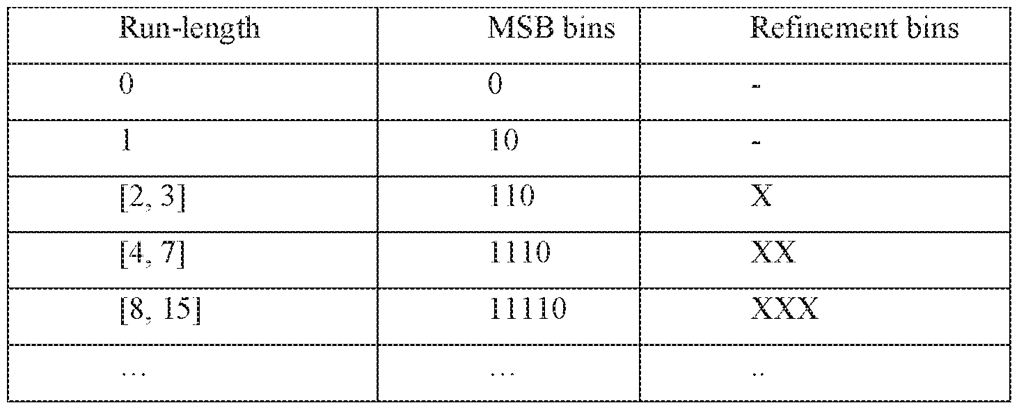
[0040] For a current pixel, the maximum value of its run-length may be bounded by the distance between the pixel and the end of the coding unit. For example, the coding unit may have 8x8 or 64 pixels. The pixels may have corresponding palette indices, which may form an 8x8 palette index map (e.g., having 64 positions). The palette index map may be scanned in a specific scan order. The scan order may be pre-defined. For example, the palette index map may be scanned in a horizontal direction (e.g., as shown in FIG. 5A), or in a vertical direction (e.g., as shown in FIG. 5B). The 64 pixels may correspond to scan positions 0-63. If the current pixel is at scanning position 57, then the maximum run-length value for the current pixel may be 6, at which point the end of the palette index map may be reached. In thi s example scenario, the
MSB bins for the [4, 7] range may be set to be 1 1 1 instead of 1110; the refinement bins may be generated by binarizing the remainder, for example, using truncated binary code with the maximum value being equal to 2 (e.g., the nm -length minus 4), Syntax elements may be assigned to code the MSB bins and the refinement bins. For example, in the example syntax shown in Table 1, two elements palette run msb id plus 1 and palette nm refinement bits may¬ be assigned to code the MSB bins and the refinement bins, respectively. Element
palette_run_msb_id_plusl may be coded as regular bins with 8 context models. Element palette run refinement bits may be coded as bypass bins. Table 3 illustrates how the context model for the syntax element palette run msb id _plusl may be selected.
Table 3 - Example Context Mode Selection for Syntax Element palette_run_msb_id_plus 1

[0041] For a palette-coded coding unit, a "nin-to-the-end" flag may be signaled (e.g., via a syntax element palette run to end flag). The "run-to-Ae-end" flag may indicate that the current nm (e.g., in either index mode or copy-above mode) may continue to the end of the coding unit. For example, the current run may be coded using exponential Goiomb code. The syntax element palette run msb id plus I may indicate the length of refmement bits. The '"run- to-the-end" flag may be signaled when (e.g., only when) the range of possible run-length values at the current position, which may be determined based on the value of
palette run msb id plusl, covers a maximum possible run-length value pRunmax. Such a condition may be expressed as follows:
pRunmax ≤ (1 « palette_run_msb_id plusl) — 1 (1) Table 4 shows example palette coding syntax that includes a "run-to-the-end" lag (e.g., palette run to end flag).
Table 4 - Example Palette Mode Syntax with palette run to end flag
if( maxPaletteRun > 0 ) {
palette_ran__msbjd_plusl ae(v) if( palette riui msb id plus 1 > 1 ) {
if( scanPos && (1« palette_run __msb__id_j3lusl > MaxPaletteRun ) palette run to end flag ae(v) if( ! palette J ast_ran__fiag )
palette am refinement bits ae(v)
}
[0042] In some cases, a large ran of similar pixels (e.g., consecutive pixels that may have a same palette index value) may be present at the end of a coding unit and the '"ran-to-the-end" flag may be used to code those pixels. In some cases, however, a large ran of similar pixels (e.g., consecutive pixels that may have a same palette index value) may be present at the beginning of the coding unit while a small ran of similar pixels may be present at the end of the coding unit. For example, a first ran of the coding unit may have a same run-length as or a greater run-length than a last run of the coding unit. FIG. 6A show s such an example coding unit 600. As shown, if scanned horizontally, the coding unit 600 may have a ran-length of 22 at the beginning of the coding unit (e.g., the 22-pixel first ran following the starting pixel 601 in index mode) and a run-length of 1 at the end of the coding unit (e.g., the 1-pixel last run starting at pixel 655 in index mode). Applying the "run-to-the-end" flag to the coding unit 600 as is may cover only the small ran at the end of the coding unit (e.g., with a ran-length value of 1). If the coding unit 600 is flipped (e.g., by flipping the palette index map associated with the coding unit) in a direction orthogonal to the scan order (e.g., in an upside down manner), the large ran at the beginning of the coding unit (e.g., with a run-length value of 22) may be swapped to the end (e.g., as shown in FIG. 6B). Applying the "run-to-the-end" flag to the flipped coding unit may- cover a much larger run, e.g., a run-length of 22 as compared to a ran-length of 1.
[0043] Even though the example given here shows that the flipping is performed in a vertical direction (e.g., in an upside down manner), a person with ordinary skills in the art will appreciate that other manners of flipping the coding unit (or the palette index map associated with the coding unit) may be possible to take adv antage of the "run-to-the-end" flag. For example, where a vertical scan of the coding unit creates a large ran at the beginning of the coding unit (e.g., a first ran) and a small run at the end of the coding unit (e.g., a last run), the
coding unit (or the palette index map associated with the coding unit) may be flipped horizontally (e.g., from left to right) such that the large run at the beginning may be swapped to the end. In some cases, the coding unit (or the palette index map associated with the coding unit) may be flipped twice in order to create a large run at the end of the coding unit. The two flipping operations may be in directions orthogonal to each other. That is, the coding unit (or the palette index map associated with the coding unit) may be flipped horizontally first and then vertically; or, the coding unit (or the palette index map associated with the coding unit) may be flipped vertically first and then horizontally. The exact order of the flipping operations may not be significant as long as similar results may be achieved.
[0044] A video coding device (e.g., such as the video coding system 100) may provide an indication of whether a coding unit (or a palette index map associated with the coding unit) has been flipped to a video bitstream (e.g., the bitstream 120). The indication may be provided as part of the palette coding information described herein. The indication may be used to signal that the coding unit (or the palette index map associated with the coding unit) has been flipped once. The indication may also be used to signal that the coding unit (or the palette index map associated with the coding unit) has been flipped twice. The indication may comprise a flag, e.g., a syntax element palette flipping flag as shown in Table 5. A value of 1 (or true) for the flag may indicate that the coding unit (or the palette index map associated with the coding unit) has been flipped while a value of 0 (or false) may indicate otherwise. Other ways to provide the indication may be possible including, for example, utilizing a bit sequence. Furthermore, instead of using a specific value to indicate that the coding unit (or the palette index map associated with the coding unit) has not been flipped, the video coding device may decide not to send the indication in that situation.
Table 5 - Example Palette Mode Syntax with a Palette Flipping Flag

[0046] A video coding device (e.g., the video coding system 200) may receive a video bitstream (e.g., the video bitsirearn 202) and reconstruct a coding unit of the video bitstream based on palette coding information contained in the bitstream, FIG. 7 illustrates example reconstruction of a palette-coded video coding unit. As described herein, the palette coding information may describe the palette table used to encode the codmg unit and/or the palette index map of the coding unit. The palette coding information may indicate the scan order of the coding unit and/or whether the coding unit (or the palette index map associated with the coding unit) has been flipped during encoding.
[0047] The video bitstream may be entropy-decoded (e.g., at entropy decoding unit 704).
The palette table information may be sent to a palette table reconstruction unit 706 to form the palette table used during encoding. The palette table may contain the major colors of the coding unit. The palette index map information (e.g., palette indices and run lengths) may be sent to a palette index decoding unit 708. The palette index map of the coding unit may be regenerated. If a pixel of the coding unit is coded as a major color, the pixel's palette index may be used to retrieve the corresponding major color from the palette table. If the pixel is coded as an escape color (e.g., if the palette index of the pixel is greater than the maximum, palette index value of the palette table), the actual escape color value may be decoded. The decoded value of the escape color may be directly used (e.g., if lossless coding is applied) or de-quantized (e.g., if lossy- coding is applied) to reconstruct the pixel.
[0048] The video coding device may determine whether the coding unit (or the palette index map associated with the coding unit) has been flipped during encoding. The determination may be made based on the palette coding information. For example, the video coding device may check the presence and/or value of a palette flipping flag (e.g., a flag denoted as palette lipping Iag) to determine whether the coding unit (or the palette index map associated with the coding unit) has been flipped. If such a flag is not present in the bitstream or if the flag has a value of 0 (or false), the video coding device may determine that the coding unit (or the palette index map associated with the coding unit) has not been flipped. If the flag is present and has a value indicating that the coding unit (or the palette index map associated with the coding unit) has been flipped (e.g., a value of 1 or true), the video coding device may interpret the meaning of the flag in at least two ways.
|0Θ49] The video coding device may interpret the flag as indicating that the coding unit
(or the palette index map associated with the coding unit) has been flipped once during encoding. The video coding device may further determine a direction of the flipping. Such direction may be determined based on a scan order of the coding unit, which may be indicated in the bitstream. More specifically, the video coding unit may determine that the direction of the flipping is orthogonal to the scan order. For example, if the scan order is horizontal (e.g., as shown in FIGs. 5A and 6A), the video coding device may determine that the flipping has been performed in a vertical direction (e.g., in an upside down manner); if the scan order is vertical (e.g., as shown in FIG. 5B), the video coding device may determine that the flipping has been performed in a horizontal direction (e.g., in a left to right manner).
[0050] The video coding device may interpret the flag as indicating that the coding unit
(or the palette index map associated with the coding unit) has been flipped twice during encoding. The video coding device may assume that the two flipping operations have been performed in orthogonal directions (e.g., a vertical flip followed by a horizontal flip, or vice versa).
fOOSl] Upon making the determination regarding the flipping, the video coding device may process the coding unit in accordance with the determination. For example, if the determination is that the coding unit (or the palette index map associated with the coding unit) has been flipped once during encoding, the video coding device may use the determined direction of the flipping to perform, an inverse flipping of the coding unit (or the palette index map associated with the coding unit) to restore the pixels of the coding unit to their original positions in the coding unit. For instance, if it is determined that the coding unit (or the palette index map associated with the coding unit) has been flipped vertically (e.g., upside down), the inverse flipping may restore the coding unit (or the palette index map associated with the coding unit) to right side up; if it is determined that the coding unit (or the palette index map associated with the coding unit) has been flipped horizontally (e.g., from left to right), the inverse flipping may turn the coding unit (or the palette index map associated with the coding unit) from right to left to restore the original positions of the sides. If the determination is that the coding unit (or the palette index map associated with the coding unit) has been flipped twice during encoding, the video coding unit may assume that the two flipping operations have been performed in orthogonal directions, in which case the video coding device may fl ip the coding unit (or the palette index map associated with the coding unit) twice, also in orthogonal directions, without considering the order of the original flipping operations. For instance, the video coding device
may flip the coding unit vertically first and then horizontally, or vice versa, to restore the pixels of the coding unit to their original positions in the coding unit.
[0052] As described herein, an example reconstruction of a video signal palette -coded in intra prediction mode may be described as follows.
[0053] Inputs to the reconstruction may be a luma location ( xCb, yCb ), which may specify the top-left sample of a current luma coding block or coding unit relative to the top-left luma sample of a current picture, and a variable logiCbSize, which may specify the size of the current luma coding block. Output of the reconstruction may be a modified reconstructed picture before deblocking filtering. Quantization parameters may be derived by invoking the luma location { xCb, yCb } as input. A variable nCbS may be set equal to 1 « logiCbSize.
Depending on the values of pcm_flag[ xCb ][ yCb ], palette_mode_flag[ xCb ][ yCb ], and IntraSplitFlag, the luma samples may be decoded as follows.
[0054] If pcm _flag[ xCb ][ yCb ] is equal to 1, the reconstructed picture may be modified as SL[ xCb + i ][ yCb + j ] = pcm_sample_luma[ { nCbS * j } + i ] « ( BitDepthY ~
PcmBitDepthY ), with i, j = CL .nCbS - 1.
[0055] If pcm flag xCb ][ yCb ] is equal to 0 and palette mode flag | xCb ] [ yCb ] is equal to 1, the following may apply. Decoding for palette intra blocks may be invoked with one or more of following as input: the luma location ( xCb, yCb ), nCbS, a variable cldx, the value of which may be set to 0, an array paletteSampleMode, a palette indices array palettelndexMap, and/or an array of escape values (e.g., quantized escape values) paietteEscapeVal . The output of the decoding process may be an nCbS*nCbS array of reconstructed palette sample values, recSamples x ][ y ], with x, y = 0...nCbS - 1. The reconstructed picture may be modified. For example, if both palette transpose flag and palette flipping flag are true,
SL[ yCb + y ][ xCb + x ] may be set equal to recSamples[ x ][ nCbS- y ]. If
palette_transpose_flag is true and palette__flippmg__flag is false, SL[ yCb + y ][ xCb + x ] may be set equal to recSamplesf x ] [ y ]. If palette transpose flag is false and palette flipping flag is true, SL[ xCb + x ][ yCb + y ] may be set equal to recSampies[ x ][ nCbS- y ]. If both palette_transpose_flag and palette_flipping_flag are false, SL[ xCb + x ][ yCb + y ] may be set equal to recSamplesf x ][ y ].
[0056] When ChromaArrayType is not equal to 0, the following may apply. The variable logiCbSizeC may be set equal to !og2CbSize - { ChromaArrayType = = 3 ? 0 : 1 ). Depending on the values of pcm_flag[ xCb ][ yCb ] and IntraSplitFlag, the chroma samples may be decoded as follows.
|0Θ57] If pcm flagf xCb ][ yCb ] is equal to 1, the reconstructed picture may be modified. For example, Sc¾[ xCb / SubWidthC + i ][ yCb / SubHeightC +j ] may be set equal to pcm_satnple_chroma[ ( nCbS / SubWidthC * j ) + i ] « ( BitDepthc - PcmBitDepthc ), with i = 0...nCbS / SubWidthC - 1 and j = 0..nCbS / SubHeightC - 1. S&[ xCb / SubWidthC + i ][ yCb / SubHeightC + j j may be set equal to pcm sample chromaf ( nCbS / SubWidthC * ( j + nCbS / SubHeightC ) ) i I « { BitDepthc ~ PcmBitDepthc ), with i = 0.. ,nCbS / SubWidthC - 1 and j = 0..nCbS / SubHeightC - 1 .
|0Θ58] If pcm flagf xCb ][ yCb ] is equal to 0 and palette mode flag xCb ][ yCb ] is equal to 1, the following may apply .
[0059] Decoding for palette intra blocks may be invoked with one or more of the following as inputs: the chroma location ( xCb, yCb ), nCbS, a variable cidx, the value of which may be set to 1, an array paletieSarripleMode, a palette indices array palette IndexMap, and/or an array of escape values (e.g., quantized escape values) paietteEscapeVal. The output may be an nCbS*nCbS array of reconstructed palette sample values, recSamplesf x ][ y ], with x, y = 0... nCbS - 1. The reconstructed picture may be modified. For example, if both
palette transpose flag and palette flipping flag are true,
Scb[ yCb/ SubHeightC + y ][ xCb/SubWidthC + x ] may be set equal to recSamples[ x ][ nCbS/
SubHeightC - y ]. If paIette_transpose_fiag is true and palette_f!ipping_f!ag is false,
Sc¾f yCb/SubHeightC + y jf xCb/SubWidthC + x ] may be set equal to rec Samples [ x ][ y ]. If palette Jxanspose__flag is false and paiette_flipping_flag is true, Sct>[ xCb/SubWidthC + x ]
[ yCb/ SubHeightC + y ] may be set equal to recSamplesf x ][ nCbS/ SubHeightC - y ]. If both palette transpose flag and palette flipping flag are false, Scbj xCb/SubWidthC + x ]
[ yCb/ SubHeightC + y ] may be set to recSamples[ x ][ y J.
[0060] Decoding for palette intra blocks may be invoked again with one or more of the following as inputs: the chroma location ( xCb, yCb ), nCbS, the variable cidx, the value of which may be set to 2, the array paletteSampleMode, the palette indices array palettelndexMap, and/or the array of escape values (e.g., quantized escape values) paietteEscapeVal. The output may be an nCbS*nCbS array of reconstructed palette sample values, recSamples[ x ][ y ], with x, y = 0...nCbS - 1 . The reconstructed picture may be modified. For example, if both palette transpose flag and palette flipping flag are true,
Scb[ yCb/ SubHeightC + y ][ xCb/SubWidthC + x ] may be set equal to recSamples[ x ][ nCbS/
SubHeightC - y ]. If palette_transpose_flag is true and palette_f!ipping_f!ag is false,
Sc f yCb/SubHeightC + y jf xCb/SubWidthC + x ] may be set equal to rec Samples [ x ][ y ]. If palette transpose flag is false and palette flipping flag is true, Sa>[ xCb/SubWidthC + x ]
[ yCb/ SubHeightC + y ] may be set equal to recSamples[ x ] [ nCbS/ SubHeightC - y ]. If both palette transpose flag and palette flipping flag are false, So>[ xCb/SubWidthC + x ]
[ yCb/ SubHeightC + y ] may be set equal to recSamples[ x ][ y ].
[0061] The example decoding process described herein may be applied for different value combinations of palette transpose flag and palette flipping flag and for the lunia and chroma components. Although an example implementation of the "flipping" operation is described, e.g., the pixel value at position "nCbS - y" in the y axis is decoded to that position and "flipped" (e.g., moved or copied in memory) to replace the pixel value at position "y" in the y axis, other implementations of palette flipping may be used. For example, one or more scan orders (e.g., multiple different scan orders) may be stored (e.g., pre-stored) at the decoder. The scan orders may be used for different value combinations of palette_transpose_flag and palette flipping flag and/or for blocks with different sizes. A stored scan order may correspond to a pair of palette transpose flag and palette flipping flag values. For example,
palette_transpose_flag and palette_flipping_flag may have one of the following value pairs: {0,0}, {0,1 }, { 1,0}, or { 1, 1 }. The palette transpose flag and palette flipping flag value pair may have a corresponding scan order stored at the decoder. Depending on the values of palette_transpose_flag and palette_flipping_flag received in the video bitstream, a corresponding scan order may be selected and applied in the decoding. The selected scan order may be used to decode the pixels into a final ordering of the pixels. For example, the pixels may be transposed, flipped, both transposed and flipped, or neither transposed nor flipped. The effect of "flipping" may be achieved even though the pixel values are not decoded along an initial scan pattern and then moved or copied. Memory consumption and on-the-fly calculation of coordinate values may be reduced.
[0062] The result from flipping a palette-code coding unit (or a palette index map associated with the coding unit) may vary based on the characteristics of the coding unit. For example, a coding unit with a small block size and/or large number of major colors (e.g., a large palette table) may have small run-length values in either or both of the index mode and copy- above mode. In such case, the gain from flipping the coding unit (or the palette index map associated with the coding unit) may be outweighed by the signaling overhead involved.
Accordingly, the application of the palette flipping operation may be conditioned on the block size and/or the palette table size of the coding unit. A pre-defined threshold may be used to determine whether to flip a coding unit (or a palette index map associated with the coding unit) and signal the flipping. For example, the pre-defined threshold may be set to a block size of 8x8 pixels and/or a palette table size of 10. A coding unit smaller than or equal to the threshold block
size and/or having a palette table larger than the threshold palette table size may not be flipped (and flipping indication may be skipped).
[0063] Similar thresholds as described herein may be used to determine whether performance comparison (e.g., via testing) between applying and not applying palette flipping should be conducted for determining which of the two actions to take. Such performance comparison may be disabled if a coding unit's size is smaller than or equal to a predefined threshold block size (e.g., 8x8 pixels), and/or if the number of major colors in the coding unit is greater than a predefined threshold (e.g., a threshold of 10).
[0064] Performance comparison may be conducted between applying and not applying palette flipping for one or more, but not all, scan orders. As described herein, at least two scan orders (e.g., horizontal scan and vertical scan) may be supported in palette coding. Instead of comparing the performance of enabling and disabling palette flipping for all of the scan orders, the comparison may be performed for a subset of the scan orders (e.g., for only one scan order that offers the best coding performance). Further, palette flipping may be disabled for coding units that have larger last run-length than first run-length. This way, the "run-to-the-end" flag may be applied to the larger of the first run-length and the last run-length.
[0065] As described herein, at least two prediction modes, e.g., the index mode and copy- above mode, may be used in palette coding. The video coding device may determine which prediction mode to use and/or what the proper run-length is. In an example, the video coding device may derive and apply the largest possible run-length for a selected prediction mode (e.g., the index mode or the copy-above mode). Using the largest run -length may not be optimal, however, in at least some cases. For example, it may be possible to code one or more pixels of a coding unit in the index mode and one or more subsequent pixels in the copy-above mode. This is referred to herein as index-followed-by-copy -above. In these and other cases, different combinations of index and copy-above run-length values may be jointly considered, tested and/or compared to determine a prediction mode to use and/or the corresponding run-length.
[0066] FIG. 8 illustrates an example method for selecting a palette prediction mode and/or run-length. At 802, a first pixel of a current coding unit is initialized as scan position k = 0 and a bit cost is initialized as MAX (e.g., MAX may be set to a maximum cost value such as MAX DOUBLE). If the index mode is disabled, the method may proceed to 818. Otherwise, at 804, starting from, the current scan position k, a maximum run-length values Run1 in the index mode may be derived for the current scan position. The bit cost Bl associated with coding the palette indices of the next (i?unl + l) scan positions in the index mode may be calculated.
Bl may be expressed as R(rnodemdex) + R(Indexh) + fl(i?unl) . The variable Indexk may represent the palette index value at scan position k. The functions may represent the bit costs associated with signaling the index mode, the index value, and the index mode run-length at scan position k, respectively.
[0067] At 806-814, for one or more values of I between Run1— 1 and 0, a maximum run-length value Runfomb in the copy -above mode may be derived for the pixel at scan position k + I + 1. For one or more values of /, the bit cost Bfomb associated with coding the palette indices of the next (I + 1) scan positions in the index mode and coding the palette indices of the following (Runc l omb + l) scan positions in the copy-above mode may be calculated. The bit cost Bfomb may be expressed as Bfomh = R(modecomb) + R(lndexk) + R(l) + R(Runfomb). The function R(modecomb) may represent the bit cost associated with signaling the index mode at scan position k and the copy-above mode at scan position k + I + 1. The function R(lndexk) may represent the bit cost associated with signaling the palette index value Indexk at scan position k. The functions R(l) and R(Runc l omb^ may represent the bit costs associated with signaling the index mode run-length / and the copy -above mode run-length Runi °mb, respectively. The minimum coding bit cost among all potential values of / may be saved as the minimum combination coding bit cost, B^^ , for index-followed-by-copy -above.
|0068] At 818, if the copy -above mode is enabled for the current scan position k, the bit cost Bc for coding the palette indices of the next (Ru?ic + 1) scan positions in the copy-above mode may be calculated. The bit cost may be expressed as Bc = R(rnodecopy~above) + R(Runc).
|0Θ69] A per-pixel average coding bit cost may be calculated for the index mode coding bit cost B copy-above mode coding bit cost Bc, and the minimum combination mode coding bit cost B j™b. For example, the per-pixel average coding bit cost may be derived by dividing the coding bit cost of each candidate coding mode by the number of pixels that could be coded using that coding mode. A palette coding mode may be selected for the current scan position k by comparing the per-pixel bit cost described herein. For example, the palette coding mode having the smallest per-pixel bit cost may be selected, as illustrated in the following:

Ί {l+Runf comb
|0Θ70] The palette mode selection method described herein may be repeated for one or more subsequent scan positions k, where k = k + Runs + 1 , until, for example, all positions in the current coding unit have been coded.
[0071] Various techniques may be employed to control the coding complexity associated with the palette mode selection method described herein. The method may be selectively applied. For example, the method may be enabled for coding units with large run-length values (e.g., bigger coding units) and disabled for small coding units (e.g., coding units with 8x8 pixels or less). The interval for testing the potential combinations of an index run followed by a copy- above run may be adjusted to control the number of tests to be conducted. For example, a threshold may be predefined for the overall run-length (e.g., Z + Runfomb in (3)). If the overall run-length is greater than the threshold, testing may be conducted for every two increments of/; otherwise, testing may be conducted for every one increment of/. The increment interval or step size of / may be adjusted. For example, a larger step size (e.g., a step size of 4) may be used initially (or the initial step size may be set based on the index mode run-length value Run'). If the initial step size (e.g., a larger step size) fails to find a proper combined mode (e.g., index- followed-copy-above), or if the copy-above mode is not available, the step size may be decreased by certain amount (e.g., gradually decreased) for further testing, until a satisfactory combined mode is found, or until the step size has been decreased to 1.
[0072] Various search algorithms may be employed to control the complexity associated with identifying a combined mode. Example algorithms may include binary search, interpolation search, and/or the like. Early termination may be applied such that searching may be terminated when the bit cost value starts to increase. For example, if a combined mode being tested has an index run-length of / and the bit cost for the combined mode is already higher than the smallest bit cost derived thus far, further testing of other combined modes with smaller index mode run- length values, e.g., Z— 1, Z— 2, ... ,0, may no longer be necessary and the search may be terminated.
[0073] Palette information of pre viously -coded coding units may be re-used. A palette sharing mode may be employed for such purpose. An indication (e.g., the syntax element palette share flag shown in Table 1) may be provided to signal palette sharing. The indication may be interpreted by a video coding device (e.g., the video coding system 200) as signaling that no new palette entries (e.g., no non-predicted palette colors) are being signaled for a current palette table. A predictor list may be provided to facilitate palette sharing. The predictor list
may include one or more colors thai may be re-used to code a current coding unit. Re-use may be signaled, e.g., via the palette predictor run syntax element shown in Table 1.
[0074] Table 6 shows example syntax for palette sharing. Note that the value of palette_num_signalled_entries may be derived by adding 1 to the value of the signaled syntax element palette num signalled entries minus 1.
[0075] Various palette table derivation techniques may be used to derive candidate palette tables in palette sharing mode and/or to decide (e.g., from a rate -distortion perspective) which of the candidate palette tables should be chosen for a current CU. One or more of these techniques may be combined with other palette table derivation techniques. For example, the candidates produced by these techniques may be compared with candidates derived for other coding modes (e.g., coding modes other than the palette sharing mode).
[0076] In an example palette table derivation technique, a video coding device (e.g., the video coding system 100) may derive the palette table for a current coding unit based on the palette predictor list. The palette table of the last palette-coded CU may be re-used. The size of the derived palette table may be equal to the size of the last palette-coded CU. A re-use indication (e.g., a re-use flag) for palette predictor may be set for an entry on the palette predictor list. For example, a re-use indication value of 1 may indicate that the corresponding entry on the palette predictor list belongs to the palette table of the last palette coded CU and may be re-used for the current coding unit.
[0077] In an example palette table derivation technique, a usage histogram may be generated, e.g., based on the palette predictor list. For example, if the sample value of a pixel can be matched with a color entry in the palette predictor list, a counter for that color entiy may be increased by 1, and/or the color entry may be regarded as a used predictor. The matching may indicate that the diffe ence between the sample value and the palette table entry may be within a certain error limit. Tire specific value of the error limit may depend on one or more quantization parameters. The usage histogram may be sorted in a descending order. The palette predictors on the sorted histogram may be added to (e.g., used to form) the current palette table in the sorted order (e.g., those with larger counter values after the matching and/or counting will be added first), until the number of added predictors reaches the maximum palette table size. At that point, no more of the remaining used predictors may be added to the palette table.
Table 6 - Example Palette Sharing Syntax
palette_coding( x0, yO, nCbS ) { Descriptor palette share flag [ xO ] [ yO ] ae(v) paiettePredietionFinished = 0
paletteNumPredictedEntries =: 0
for( i = 0; i < PredictorPaielteSize && !palettePredictionFinished &&
paletteNumPredictedEntries < palette_max_size; i++ ) {
pal ette predictor run ae(v) if( palette_predictor_run != 1 )
if( palette predictor run > 1 )
i += palette_predictor_run - 1
PalettePredictorEntryReuseFlag[ i j := 1
pal etteNumPredictedEntries ++
} else
paiettePredietionFinished = 1
}
if( !palette_share_flag[ xO ][ yO ] ) {
if( paletteNumPredictedEntries < palette max size )
palette_num_signalled_entries_minusl ae(v) for( cldx = 0; cldx < 3; cldx-K- )
for( i = 0; i < palette_nun _signalled_ entries; i++ )
palette entry ae(v) if( currentPaletteSize ! = 0 )
palette_escape_val_present_flag ae(v) if( palette escape val present flag ) {
if( cu qp delta enabled flag && ! IsCuQpDeitaCoded ) {
cu_qp_delta_palette_abs ae(v) if( cu qp delta palette ahs )
cu_qp_delta_palette_sign_flag ae(v)
}
if( cu chroma qp offset enabled flag && ! IsCuChromaQpOffsetCoded )
{
cu chroma qp palette offset flag ae(v) if( cu chroma qp offset flag && chroma qp offset list len minus 1 >
0 )
cu chroma qp palette offset idx ae(v)
}
}
if( indexMax > 0)

}
runPos-H- scanPos++
}
[0078] A video coding device (e.g., the video coding system 100) may select a palette table derivation technique from a group of potential palette table derivation techniques. The selection may be made based on rate-distortion cost. For example, the video coding device may check the non-sharing mode and derive a palette table candidate for the non-sharing mode. The video coding device may derive a palette table candidate for the palette sharing mode, e.g., using an example technique described herein (e.g., the technique utilizing usage histogram, as described herein). Based on these candidates, the video coding device may select a coding mode. If the selected coding mode is not the sharing mode and/or if the selected mode is not a palette coding mode, the video coding device may derive another candidate palette table (e.g., by using an example palette table derivation technique described herein). From all of the candidate palette tables, the video coding device may select one with the minimal rate-distortion cost. It should be noted that if the selected coding mode described herein is the sharing mode, the video coding device may skip applying the first example technique.
[0079] FIG. 9A is a diagram of an example communications system 1000 in which one or more examples disclosed herein may be implemented. The communications system 1000 may be a multiple access system that provides content, such as voice, data, video, messaging, broadcast, etc., to multiple wireless users. The communications system 1000 may enable multiple wireless users to access such content through the sharing of system resources, including wireless bandwidth. For example, the communications systems 1000 may employ one or more channel access methods, such as code division multiple access (CDMA), time division multiple access (TDMA), frequency division multiple access (FDMA), orthogonal FDMA (OFDMA), single-carrier FDMA (SC-FDMA), and the like.
[0080] As shown in FIG. 9A, the communications system 1000 may include wireless transmit/receive units (WTRUs) 1002a, 1002b, 1002c, and/or 1002d (which generally or collectively may be referred to as WTRU 1002), a radio access network (RAN) 1003/1004/1005, a core network 1006/1007/1009, a public switched telephone network (PSTN) 1008, the Internet 1010, and other networks 1012, though it will be appreciated that the disclosed embodiments
contemplate any number of WTRUs, base stations, networks, and/or network elements. Each of the WTRUs 1002a, 1002b, 1002c, 1002d may be any type of device configured to operate and/or communicate in a wireless environment. By way of example, the WTRUs 1002a, 1002b, 1002c, 1002d may be configured to transmit and/or receive wireless signals and may include user equipment (UE), a mobile station, a fixed or mobile subscriber unit, a pager, a cellular telephone, a personal digital assistant (PDA), a smartphone, a laptop, a netbook, a personal computer, a wireless sensor, consumer electronics, and the like.
[0081] The communications systems 1000 may also include a base station 1014a and a base station 1014b. Each of the base stations 1014a, 1014b may be any type of device configured to wirelessly interface with at least one of the WTRU s 1002a, 1002b, 1002c, 1002d to facilitate access to one or more communication networks, such as the core network
1006/1007/1009, the Internet 1010, and/or the networks 1012. By way of example, the base stations 1014a, 1014b may be a base transceiver station (BTS), a ode-B, an eNode B, a Home Node B, a Home eNode B, a site controller, an access point (AP), a wireless router, and the like. While the base stations 1014a, 1014b are each depicted as a single element, it will be appreciated that the base stations 1014a, 1014b may include any number of interconnected base stations and/or network elements.
[0082] The base station 1014a may be part of the RAN 1003/1004/1005, which may also include other base stations and/or network elements (not shown), such as a base station controller (BSC), a radio network controller (RNC), relay nodes, etc. The base station 1014a and/or the base station 1014b may be configured to transmit and/or receive wireless signals within a particular geographic region, which may be referred to as a cell (not shown). The cell may further be divided into cell sectors. For example, the cell associated with the base station 1014a may be divided into three sectors. Thus, in one embodiment, the base station 1014a may include three transceivers, i .e., one for each sector of the cell . In another embodiment, the base station 1014a may employ multiple-input multiple output (MIMO) technology and, therefore, may- utilize multiple transceivers for each sector of the ceil.
[0083] The base stations 1014a, 1014b may communicate with one or more of the
WTRUs 1002a, 1002b, 1002c, 1002d over an air interface 1015/ 1016/ 1017, which may be any suitable wireless communication link (e.g. , radio frequency (RF), microwave, infrared (IR), ultraviolet (UV), visible light, etc.). The air interface 1015/1016/1017 may be established using any suitable radio access technology (RAT).
[0084] More specifically, as noted above, the communications system 1000 may be a multiple access system and may employ one or more channel access schemes, such as CDMA,
TDMA, FDMA, OFDMA, SC-FDMA, and the like. For example, the base station 1014a in the RAN 1003/1004/1005 and the WTRUs 1002a, 1002b, 1002c may implement a radio technology such as Universal Mobile Telecommunications System (UMTS) Terrestrial Radio Access (UTRA), which may establish the air interface 1015/1016/1017 using wideband CDMA (WCDMA). WCDMA may include communication protocols such as High-Speed Packet Access (HSPA) and/or Evolved HSPA (HSPA+). HSPA may include High-Speed Downlink Packet Access (HSDPA) and/or High-Speed Uplink Packet Access (HSUPA).
|0Θ85] In another embodiment, the base station 1014a and the WTRUs 1002a, 1002b,
1002c may implement a radio technology such as Evolved U MTS Terrestrial Radio Access (E- UTRA), which may establish the air interface 1015/1016/1017 using Long Term Evolution (LTE) and/or LTE-Advanced (LTE- A).
[0086] In other embodiments, the base station 1014a and the WTRUs 1002a, 1002b,
1002c may implement radio technologies such as IEEE 802.16 (i.e., Worldwide Interoperability for Microwave Access (WiMAX)), CDMA2000, CDMA2000 IX, CDMA2000 EV-DO, Interim Standard 2000 (IS-2000), Interim Standard 95 (IS-95), Interim Standard 856 (IS-856), Global System for Mobile communications (GSM), Enhanced Data rates for GSM Evolution (EDGE), GSM EDGE (GERAN), and the like.
[0087] The base station 1 14b in FIG. 9A may be a wireless router, Home Node B,
Home eNode B, or access point, for example, and may utilize any suitable RAT for facilitating wireless connectivity in a localized area, such as a place of business, a home, a vehicle, a campus, and the like. In one embodiment, the base station 1014b and the WTRUs 1002c, 1002d may implement a radio technology such as IEEE 802.11 to establish a wireless local area network (WLAN). In another embodiment, the base station 1014b and the WTRUs 1002c, 1002d may implement a radio technology such as IEEE 802.15 to establish a wireless personal area network (WPAN) . In yet another embodiment, the base station 1014b and the WTRUs 1002c, 1002d may utilize a cellular-based RAT (e.g. , WCDMA, CDMA2000, GSM, LTE, LTE- A, etc.) to establish a picocell or femtocell. As shown in FIG. 9A, the base station 1014b may have a direct connection to the Internet 1010. Thus, the base station 1014b may not be required to access the Internet 1010 via the core network 1006/1007/1009.
[0088] The RAN 1003/1004/1005 may be in communication with the core network
1006/1007/1009, which may be any type of network configured to prov ide voice, data, applications, and/or voice over internet protocol (VoIP) services to one or more of the WTRUs
1002a, 1002b, 1002c, 1002d. For example, the core network 1006/1007/1009 may provide call control, billing services, mobile location-based services, pre-paid calling, Internet connectivity,
video distribution, etc., and/or perform high-level security functions, such as user authentication. Although not shown in FIG. 9A, it will be appreciated that the RAN 1003/1004/1005 and/or the core network 1006/1007/1009 may be in direct or indirect communication with other RANs that employ the same RAT as the RAN 1003/1004/1005 or a different RAT. For example, in addition to being connected to the RAN 1003/1004/1005, which may be utilizing an E-UTRA radio technology, the core network 1006/1007/1009 may also be in communication with another RAN (not shown) employing a GSM radio technology.
|0Θ89] The core network 1006/1007/1009 may also serve as a gateway for the WTRUs
1002a, 1002b, 1002c, 1002d to access the PSTN 1008, the Internet 1010, and/or other networks 1012. The PST 1008 may include circuit-switched telephone networks that provide plain old telephone service (POTS). The internet 1010 may include a global system of interconnected computer networks and devices that use common communication protocols, such as the transmission control protocol (TCP), user datagram protocol (U DP) and the internet protocol (IP) in the TCP/IP internet protocol suite. The networks 1012 may include wired or wireless communications networks owned and/or operated by other sen-ice providers. For example, the networks 1012 may include another core network connected to one or more RANs, which may employ the same RAT as the RAN 1003/1004/1005 or a different RAT.
[0090] Some or all of the WTRUs 1002a, 1002b, 1002c, 1002d in the communications system 1000 may include multi-mode capabilities, i.e., the WTRUs 1002a, 1002b, 1002c, 1002d may include multiple transceivers for communicating with different wireless networks over different wireless links. For example, the WTRU 1002c shown in FIG. 9A may be configured to communicate with the base station 1014a, which may employ a cellular-based radio technology, and with the base station 1014b, which may employ an IEEE 802 radio technology .
[0091] FIG. 9B is a system diagram, of an example WTRU 1002. As shown in FIG. 9B, the WTRU 1002 may include a processor 1018, a transceiver 1020, a transmit/receive element 1022, a speaker/microphone 1024, a keypad 1026, a display /touchpad 1028, non-removable memory 1030, removable memory 1032, a power source 1034, a global positioning system (GPS) chipset 1036, and other peripherals 1038. It will be appreciated that the WTRU 1002 may- include any sub-combination of the foregoing elements while remaining consistent with an embodiment. Also, embodiments contemplate that the base stations 1014a and 1014b, and/or the nodes that base stations 1014a and 1014b may represent, such as but not limited to transceiver station (BTS), a Node-B, a site controller, an access point (AP), a home node-B, an evolved home node-B (eNodeB), a home evolved node-B (HeNB), a home evolved node-B
gateway, and proxy nodes, among others, may include some or all of the elements depicted in FIG. 9B and described herein.
[0092] The processor 1018 may be a general purpose processor, a special purpose processor, a conventional processor, a digital signal processor (DSP), a plurality of
microprocessors, one or more microprocessors in association with a DSP core, a controller, a microcontroller, Application Specific Integrated Circuits (ASICs), Field Programmable Gate Array (FPGAs) circuits, any other type of integrated circuit (IC), a state machine, and the like. The processor 1018 may perform signal coding, data processing, power control, input/output processing, and/or any other functionality that enables the WTRU 1 02 to operate in a wireless environment. The processor 1018 may be coupled to the transceiver 1020, which may be coupled to the transmit/receive element 1022. While FIG. 9B depicts the processor 1018 and the transceiver 1020 as separate components, it will be appreciated that the processor 1018 and the transceiver 1020 may be integrated together in an electronic package or chip.
[0093] The transmit/receive element 1012 may be configured to transmit signals to, or receive signals from, a base station (e.g., the base station 1014a) over the air interface
1015/1016/1017. For example, in one embodiment, the transmit/receive element 1012 may be an antenna configured to transmit and/or receive RF signals. In another embodiment, the transmit/receive element 1 22 may be an emitter/detector configured to transmit and/or receive IR, UV, or visible light signals, for example. In yet another embodiment, the transmit/receive element 1022 may be configured to transmit and receive both RF and light signals. It will be appreciated that the transmit/receive element 1022 may be configured to transmit and/or receive any combination of wireless signals.
[0094] In addition, although the transmit/receive element 1022 is depicted in FIG. 9B as a single element, the WTRU 1002 may include any number of transmit/receive elements 1022.
More specifically, the WTRU 1002 may employ MIMO technology. Thus, in one embodiment, the WTRU 1002 may include two or more transmit/receive elements 1022 (e.g., multiple antennas) for transmitting and receiving wireless signals over tlie air interface 1015/1016/1017.
[0095] The transceiver 1020 may be configured to modulate the signals that are to be transmitted by the transmit/receive element 1022 and to demodulate the signals that are received by the transmit/receive element 1022. As noted above, the WTRU 1002 may have multi-mode capabilities. Thus, the transceiver 1020 may include multiple transceivers for enabling the
WTRU 1002 to communicate via multiple RATs, such as UTRA and IEEE 802.1 1 , for example.
[0096] The processor 1018 of the WTRU 1002 may be coupled to, and may receive user input data from, the speaker/microphone 1024, the keypad 1026, and/or the display /touchpad
1028 (e.g., a liquid crystal display (LCD) display unit or organic light-emitting diode (OLED) display unit). The processor 1018 may also output user data to the speaker/microphone 124, the keypad 1026, and/or the display/touchpad 1028. In addition, the processor 1018 may access information from, and store data in, any type of suitable memory, such as the non-removable memory 1030 and/or the removable memory 1032. The non-removable memory 1030 may include random-access memory (RAM), read-only memosy (ROM), a hard disk, or any other type of memory storage device. The removable memory 1 32 may include a subscriber identity- unit (SIM) card, a memory stick, a secure digital (SD) memory card, and the like. In other embodiments, the processor 1018 may access information from, and store data in, memory that is not physically located on the WT'RU 1002, such as on a server or a home computer (not shown).
[0097] The processor 1 18 may receive power from the power source 1 34, and may be configured to distribute and/or control the power to the other components in the WTRU 1002. The power source 1034 may be any suitable device for powering the WTRU 1002. For example, the power source 1 34 may include one or more dry cell batteries (e.g., nickel-cadmium (NiCd), nickel-zinc (NiZn), nickel metal hydride (NiMH), lithium-ion (Li-ion), etc.), solar cells, fuel cells, and the like.
[0098] The processor 1018 may also be coupled to the GPS chipset 1036, which may be configured to provide location information (e.g., longitude and latitude) regarding the current location of the WTRU 1002. In addition to, or in lieu of, the information from the GPS chipset 1036, the WTRU 1002, may receive location information over the air interface 1015/1016/1017 from a base station (e.g., base stations 1014a, 1014b) and/or determine its location based on the timing of the signals being received from two or more nearby base stations. It will be appreciated that the WTRU 1002 may acquire location information by way of any suitable location-determination method while remaining consistent with an embodiment.
[0099] The processor 1018 may further be coupled to other peripherals 1 038, which may include one or more software and/or hardware units that provide additional features, functionality and/or wired or wireless connectivity. For example, the peripherals 1038 may- include an accelerometer, an e-compass, a satellite transceiver, a digital camera (for photographs or video), a universal serial bus (USB) port, a vibration device, a television transceiver, a hands free headset, a Bluetooth® unit, a frequency modulated (FM) radio unit, a digital music play er, a media player, a video game player unit, an internet browser, and the like.
[0100] FIG. 9C is a system diagram of the RAN 1003 and the core network 1006 according to an embodiment. As noted above, the RAN 1003 may employ a UTRA radio technology to communicate with the WTRUs 1002a, 1002b, 1002c over the air interface 1015.
The RAN 1003 may also be in communication with the core network 1006. As shown in FIG. 9C, the RAN 1003 may include Node-Bs 1040a, 1040b, 1040c, which may each include one or more transceivers for communicating with the WTRUs 1002a, 1002b, 1002c over the air interface 1015. The Node-Bs 1040a, 1040b, 1040c may each be associated with a particular cell (not shown) w ith in the R A N 1003. The RAN 1003 may also include R Cs 1042a, 1042b. It will be appreciated that the RAN 1003 may include any number of Node-Bs and RNCs while remaining consistent with an embodiment.
[0101] As shown in FIG. 9C, the Node-Bs 1040a, 1040b may be in communication with the RNC 1042a. Additionally, the Node-B 1040c may be in communication with the
RNC1042b. The Node-Bs 1040a, 1040b, 1040c may communicate with the respective RNCs 1042a, 1042b via an Tub interface. The RNCs 1042a, 1042b may be in communication with one another via an Iur interface. Each of the RNCs 1042a, 1042b may be configured to control the respective Node-Bs 1040a, 1040b, 1040c to which it is connected. In addition, each of the RNCs 1042a, 1042b may be configured to cany out or support other functionality, such as outer loop power control, load control, admission control, packet scheduling, handover control, macrodiversity, security functions, data encryption, and the like.
[0102] The core network 1006 shown in FIG. 9C may include a media gateway (MGW)
1044, a mobile switching center (MSC) 1046, a serving GPRS support node (SGSN) 1048, and/or a gateway GPRS support node (GGSN) 1050. While each of the foregoing elements are depicted as part of the core network 1006, it will be appreciated that any one of these elements may be owned and/or operated by an entity other than the core network operator.
[0103] The RNC 1042a in the RAN 1003 may be connected to the MSC 1046 in the core network 1006 via an luCS interface. The MSC 1046 may be connected to the MGW 1044. The MSC 1046 and the MGW 1044 may provide the WTRUs 1002a, 1002b, 1002c with access to circuit-switched networks, such as the PSTN 1008, to facilitate communications between the WTRUs 1002a, 1002b, 1002c and traditional land-line communications devices.
[0104] The RNC 1042a in the RAN 1003 may also be connected to the SGSN 1048 in the core network 1006 via an luPS interface. The SGSN 1048 may be connected to the GGSN 1050. The SGSN 1048 and the GGSN 1050 may provide the WTRUs 1002a, 1002b, 1002c with access to packet-switched networks, such as the Internet 1010, to facilitate communications between and the WTRUs 1002a, 1002b, 1002c and IP -enabled devices.
[0105] As noted above, the core network 1006 may also be connected to the networks
1012, which may include other wired or wireless networks that are owned and/or operated by other se dee providers.
|0106] FIG. 9D is a system diagram of the RAN 1004 and the core network 1007 according to an embodiment. As noted above, the RAN 1004 may employ an E-UTRA radio technology to communicate with the WTRUs 1002a, 1002b, 1002c over the air interface 1016. The RAN 1 04 may also be in communication with the core network 1 07.
[0107] The RAN 1004 may include eNode-Bs 1060a, 1060b, 1060c, though it will be appreciated that the RAN 1004 may include any number of eNode-Bs while remaining consistent with an embodiment. The eNode-Bs 1060a, 1060b, 1060c may each include one or more transceivers for communicating with the WTRUs 1002a, 1002b, 1002c over the air interface 1016. In one embodiment, the eNode-Bs 1060a, 1060b, 1060c may implement MIMO technology. Thus, the eNode-B 1060a, for example, may use multiple antennas to transmit wireless signals to, and receive wireless signals from, the WTRU 1002a.
[0108] Each of the eNode-Bs 1060a, 1060b, 1060c may be associated with a particular cell (not shown) and may be configured to handle radio resource management decisions, handover decisions, scheduling of users in the uplink and/or downlink, and the like. As shown in FIG. 9D, the eNode-Bs 1060a, 1060b, 1060c may communicate with one another over an X2 interface.
[0109] The core network 1007 shown in FIG. 9D may include a mobility management gateway (MME) 1062, a serving gateway 1064, and a packet data network (PDN) gateway 1 66. While each of the foregoing elements are depicted as part of the core network 1007, it will be appreciated that any one of these elements may be owned and/or operated by an entity other than the core network operator,
[0110] The MME 1062 may be connected to each of the eNode-Bs 1060a, 1060b, 1060c in the RAN 1004 via an S I interface and may serve as a control node. For example, the MME 1062 may be responsible for authenticating users of the WTRUs 1002a, 1002b, 1002c, bearer activation/deactivation, selecting a particular serving gateway during an initial attach of the WTRUs 1002a, 1002b, 1002c, and the like. The MME 1062 may also provide a control plane function for switching between the RAN 1004 and other RA s (not shown) that employ other radio technologies, such as GSM or WCDMA.
[0111] The serving gateway 1064 may be connected to each of the eNode-Bs 1060a,
1060b, 1060c in the RAN 1004 via the S I interface. The serving gateway 1064 may generally route and forward user data packets to/from the WTRUs 1002a, 1002b, 1002c. The serving gateway 1064 may also perform other functions, such as anchoring user planes during inter- eNode B handovers, triggering paging when downlink data is available for the WTRUs 1002a,
1002b, 1002c, managing and storing contexts of the WTRUs 1002a, 1002b, 1002c, and the like.
|0112] The serving gateway 1064 may also he connected to the PDN gateway 1066, which may provide the WTRUs 1002a, 1002b, 1002c with access to packet-switched networks, such as the Internet 1010, to facilitate communications between the WTRUs 1002a, 1002b, 1002c and IP-enabled devices,
[0113] The core network 1007 may facilitate communications with other networks. For example, the core network 1007 may provide the WTRUs 1002a, 1002b, 1002c with access to c rcuit-switched networks, such as the PSTN 1008, to facilitate communications between the WTRUs 1002a, 1002b, 1002c and traditional land-line communications devices. For example, the core network 1007 may include, or may communicate with, an IP gateway (e.g. , an IP multimedia subsystem (IMS) server) that serves as an interface between the core network 1007 and the PSTN 1008. In addition, the core network 1007 may provide the WTRUs 1002a, 1002b, 1002c with access to the networks 1012, which may include other wired or wireless networks that are owned and/or operated by other service providers.
[0114] FIG. 9E is a system diagram of the RAN 1005 and the core network 1009 according to an embodiment. The RAN 1005 may be an access service network (ASN) that employs IEEE 802.16 radio technology to communicate with the WTRUs 1002a, 1002b, 1002c over the air interface 1017. As will be further discussed below, the communication links between the different functional entities of the WTRUs 1002a, 1002b, 1002c, the RAN 1005, and the core network 1009 may be defined as reference points.
[0115] As show I) in FIG. 9E, the RAN 1005 may include base stations 1080a, 1080b,
1080c, and an ASN gateway 1082, though it will be appreciated that the RAN 1005 may include any number of base stations and ASN gateways while remaining consistent with an embodiment.
The base stations 1080a, 1080b, 1080c may each be associated with a particular cell (not shown) in the RAN 1005 and may each include one or more transceivers for communicating with the
WTRUs 1002a, 1002b, 1002c over the air interface 1017. In one embodiment, the base stations
1080a, 1080b, 1080c may implement MIMO technology. Thus, the base station 1080a, for example, may use multiple antennas to transmit wireless signals to, and receive wireless signals from, the WTRU 1002a. The base stations 1080a, 1080b, 1080c may also provide mobility management functions, such as handoff triggering, tunnel establishment, radio resource management, traffic classification, quality of service (QoS) policy enforcement, and the like.
The ASN gateway 1082 may serve as a traffic aggregation point and may be responsible for paging, caching of subscriber profiles, routing to the core network 1 09, and the like.
[0116] The air interface 1017 between the WTRUs 1002a, 1002b, 1002c and the RAN
1005 may be defined as an I I reference point that implements the IEEE 802.16 specification. In
addition, each of the WTRUs 1002a, 1002b, 1002c may establish a logical interface (not shown) with the core network 1009. The logical interface between the WTRUs 1002a, 1002b, 1002c and the core network 1009 may be defined as an R2 reference point, which may be used for authentication, authorization, IP host configuration management, and/or mobility management.
[0117] The communication link between each of the base stations 1080a, 1080b, 1080c may be defined as an R8 reference point that includes protocols for facilitating WTRU handovers and the transfer of data between base stations. The communication link between the base stations 1080a, 1080b, 1080c and the ASN gateway 1082 may be defined as an R6 reference pomt. The R6 reference point may include protocols for facilitating mobility management based on mobility events associated with each of the WTRUs 1002a, 1002b, 1002c.
[0118] As shown in FIG. 9E, the RAN 1005 may be connected to the core network 1009.
The communication link between the RAN 1005 and the core network 1009 may defined as an R3 reference point that includes protocols for facilitating data transfer and mobility management capabilities, for example. The core network 1009 may include a mobile IP home agent (MIP- HA) 1084, an authentication, authorization, accounting (AAA) server 1086, and a gateway 1088. While each of the foregoing elements are depicted as part of the core network 1009, it will be appreciated that any one of these elements may be owned and/or operated by an entity other than the core network operator.
[0119] The MIP-IIA may be responsible for IP address management, and may enable the
WTRUs 1002a, 1002b, 1002c to roam between different ASNs and/or different core networks. The MIP-HA 1084 may provide the WTRUs 1002a, 1002b, 1002c with access to packet- switched networks, such as the Internet 1010, to facilitate communications between the WTRUs 1002a, 1002b, 1002c and I -enabled devices. The AAA server 1086 may be responsible for user authentication and for supporting user services. The gateway 1088 may facilitate interworking with other networks. For example, the gateway 1088 may provide the WTRUs 1002a, 1002b, 1002c with access to circuit-switched networks, such as the PSTN 1008, to facilitate
communications between the WTRUs 1002a, 1002b, 1002c and traditional land-line
communications devices. In addition, the gateway 1088 may provide the WTRUs 1002a, 1002b, 1002c with access to the networks 1012, which may include other wired or wireless networks that are owned and/or operated by other se dee providers.
[0120] Although not shown in FIG. 9E, it will be appreciated that the RAN 1005 may be connected to other ASNs and the core network 1009 may be connected to other core networks.
The communication link between the RAN 1005 the other ASNs may be defined as an R4 reference point, which may include protocols for coordinating the mobility of the WTRUs
1002a, 1002b, 1002c between the RAN 1005 and the other ASNs. The communication link between the core network 1009 and the other core networks may be defined as an R5 reference, which may include protocols for facilitating interworking between home core networks and visited core networks.
[0121] Although features and elements are described above in particular combinations, one of ordinary skill in the art will appreciate that each feature or element can be used alone or in any combination with the other features and elements. In addition, the methods described herein may be implemented in a computer program, software, or firmware incorporated in a computer- readable medium for execution by a computer or processor. Examples of computer-readable media include electronic signals (transmitted over wired or wireless connections) and computer- readable storage media. Examples of computer-readable storage media include, but are not limited to, a read only memory (ROM), a random access memory (RAM), a register, cache memory, semiconductor memory devices, magnetic media such as internal hard disks and removable disks, magneto-optical media, and optical media such as CD-ROM disks, and digital versatile disks (DVDs). A processor in association with software may be used to implement a radio frequency transceiver for use in a WTRU, UE, terminal, base station, RNC, or any host computer.
Claims
1. A method for decoding a palette-coded video bitstream, the method comprising:
receiving the video bitstream, wherein the video bitstream. comprises palette coding information;
determining, based on the palette coding information, whether a palette index map of a coding umt of the video bitstream has been flipped: and
processing the coding unit in accordance with the determination, wherein, on a condition that the palette index map of the coding unit is determined to have been flipped, the processing comprises flipping the palette index map of the coding unit at least once to restore a plurality of pixels of the coding unit to their original positions in the coding unit.
2. The method of claim 1, wherein, on a condition that the palette index map of the coding umt is determined to have been flipped, the palette index map of the coding unit is flipped once based on a scan order comprised in the palette coding information.
3. The method of claim 2, wherein the palette index map of the coding unit is flipped in a direction orthogonal to the scan order.
4. The method of claim 1, wherein the determination of whether the palette index map of the coding unit has been flipped is based on a palette flipping flag comprised in the palette coding information.
5. The method of claim 1, wherein, on a condition that the palette index map of the coding unit is determined to have been flipped, the palette index map of the coding unit is flipped in a first direction and a second direction, the first direction being orthogonal to the second direction.
6. A method for coding a video signal using a color palette, the method comprising:
generating palette indices associated with the color palette for a coding unit of the video signal;
determining whether to flip a palette index map of the coding unit based on the palette indices, wherein, based on a determination to flip the palette index map, the palette index map of the coding unit is flipped at least once; and
providing palette coding information in a video bitstream, wherein the palette coding information comprises an indication of whether the palette index map of the coding unit has been flipped.
7. The method of claim 6, wherein, based on a determination to flip the palette index map of the coding unit, the palette index map of the coding unit is flipped once in a direction orthogonal to a scan order of the coding unit, and wherein the palette coding information comprises an indication of the scan order,
8. The method of claim 6, wherein, based on a determination to flip the palette index map of the coding unit, the palette index map of the coding unit is flipped in a first direction and a second direction, the first direction being orthogonal to the second direction,
9. The method of claim 6, wherein the indication of whether the palette index map of the coding unit has been flipped comprises a palette flipping flag.
10. The method of claim 6, wherein the determination to flip the palette index map of the coding unit is made if a first run of the palette index map has a same run-length as or a greater run-length than a last run of the palette index map.
1 1. A method for coding a video signal using a color palette, the method comprising:
determining a first cost associated with coding at least a first pixel of the video signal using index mode, wherein the index mode is enabled for the first pixel;
determining a second cost associated with coding at least the first pixel using copy -above mode, wherein the copy-above mode is enabled for the first pixel;
determining a third cost associated with coding a first run of pixels using the index mode and a second ran of pixels using the copy-above mode, wherein the first ran starts with the first pixel, the second ran starts immediately after the first run, and the third cost is a minimum cost among a plurality of combinations of run-lengths for the first and second runs; and
selecting a palette coding mode based on the first, second and third costs.
12. The method of claim 11, wherein the first cost is determined based on a maximum run- length of the index mode for the first pixel and the second cost is determined based on a maximum run-length of the copy-above mode for the first pixel.
13. The method of claim 12, wherein a palette coding mode associated with the smallest of the first, second, and third costs is selected.
14. The method of claim 11, wherein the first, second and third costs are calculated based on a per-pixel average number of bits associated with coding a plurality of pixels.
15. A video coding device for decoding a palette-coded video bitstream, the video coding device comprising:
a processor configured to:
receive the video bitstream, wherein the video bitstream comprises palette coding information;
determine, based on the palette coding information, whether a palette index map of a coding unit of the video bitstream has been flipped; and
upon determining that the palette index map of the coding unit has been flipped, flip the palette index map of the coding unit at least once to restore a plurality of pixels of the coding unit to their original positions in the coding unit.
16. The video coding device of claim 15, wherein, upon determining that the palette index map of the coding unit has been flipped, the processor is configured to flip the palette index map of the coding unit once based on a scan order comprised in the palette coding information.
17. The video coding device of claim 16, wherein the processor is configured to flip the palette index map of the coding unit in a direction orthogonal to the scan order.
18. The video coding device of claim 15, wherein the determination of whether the palette index map of the coding unit has been flipped is based on a palette flipping flag comprised in the palette coding information.
19. The video coding device of claim 15, wherein, upon determining that the palette index map of the coding unit has been flipped, the processor is configured to flip the palette index map
of the coding unit in a first direction and a second direction, the first direction being orthogonal to the second direction.
20. A video coding device for coding a video signal using a color palette, the video coding device comprising:
a processor configured to:
generate palette indices associated with the color palette for a coding unit of the video signal;
determine whether to flip a palette index map of the coding unit based on the palette indices; and
based on a determination to flip the palette index map of the coding unit:
flip the palette index map of the coding unit at least once; and
provide palette coding information in a video bitstream, wherein the palette coding information comprises an indication of whether the palette index map of the coding unit has been flipped.
2.1. The video coding device of claim 20, wherein, based on a detennination to flip the palette index map of the coding unit, the processor is configured to flip the palette index map of the coding unit once in a direction orthogonal to a scan order of the coding unit, and wherein the palette coding information comprises an indication of the scan order.
2.2. The video coding device of claim 20, wherein, based on a detennination to flip the palette index map of the coding unit, the processor is configured to flip the palette index map of the coding unit in a first direction and a second direction, the first direction being orthogonal to the second direction.
2.3. The video coding device of claim 20, wherein the indication of whether the palette index map of the coding unit has been flipped comprises a palette flipping flag.
24. The video coding device of claim 20, wherein the determination of whether to flip the palette index map of the coding unit is made if a first am of the palette index map has a same run-length as or a greater run-length than a last ran of the palette index map.
25. A video coding device for coding a video signal using a color palette, the video coding device comprising:
a processor configured to:
determine a first cost associated with coding at least a first pixel of the v ideo signal using index mode, wherein the index mode is enabled for the first pixel;
determine a second cost associated with coding at least the first pixel using copy-above mode, wherein the copy-above mode is enabled for the first pixel;
determine a third cost associated with coding a first ran of pixels using the index mode and a second run of pixels using the copy-above mode, wherein the first run starts with the first pixel, the second run starts immediately after the first nm, and the third per-pixel average bit cost is a minimum cost among a plurality of combinations of run-lengths for the first and second rans: and
select a palette coding mode based on the first, second and third costs.
26. The video coding device of claim 25, wherein the processor is configured to determine the first cost based on a maximum run-length of the index mode for the first pixel and the second cost based on a maximum run-length of the copy-above mode for the first pixel.
27. The video coding device of claim 25, wherein the processor is configured to select a palette coding mode associated with the smallest of the first, second, and third costs.
28. The video coding device of claim 25, wherein the first, second and third costs are calculated based on a per-pixel average number of bits associated with coding a plurality of pixels.
Priority Applications (3)
| Application Number | Priority Date | Filing Date | Title |
|---|---|---|---|
| EP16710506.3A EP3251353A1 (en) | 2015-01-29 | 2016-01-28 | Palette coding modes and palette flipping |
| CN201680018595.0A CN107431817B (en) | 2015-01-29 | 2016-01-28 | Method and apparatus for palette decoding |
| US15/547,121 US10484686B2 (en) | 2015-01-29 | 2016-01-28 | Palette coding modes and palette flipping |
Applications Claiming Priority (4)
| Application Number | Priority Date | Filing Date | Title |
|---|---|---|---|
| US201562109587P | 2015-01-29 | 2015-01-29 | |
| US62/109,587 | 2015-01-29 | ||
| US201562114051P | 2015-02-09 | 2015-02-09 | |
| US62/114,051 | 2015-02-09 |
Publications (1)
| Publication Number | Publication Date |
|---|---|
| WO2016123388A1 true WO2016123388A1 (en) | 2016-08-04 |
Family
ID=55543030
Family Applications (1)
| Application Number | Title | Priority Date | Filing Date |
|---|---|---|---|
| PCT/US2016/015443 Ceased WO2016123388A1 (en) | 2015-01-29 | 2016-01-28 | Palette coding modes and palette flipping |
Country Status (4)
| Country | Link |
|---|---|
| US (1) | US10484686B2 (en) |
| EP (1) | EP3251353A1 (en) |
| CN (1) | CN107431817B (en) |
| WO (1) | WO2016123388A1 (en) |
Cited By (4)
| Publication number | Priority date | Publication date | Assignee | Title |
|---|---|---|---|---|
| US11146788B2 (en) * | 2015-06-12 | 2021-10-12 | Qualcomm Incorporated | Grouping palette bypass bins for video coding |
| CN113940076A (en) * | 2019-06-06 | 2022-01-14 | 北京字节跳动网络技术有限公司 | Applying implicit transform selection |
| US12114013B2 (en) | 2019-06-06 | 2024-10-08 | Beijing Bytedance Network Technology Co., Ltd | Implicit selection of transform candidates |
| US12219138B2 (en) | 2019-06-06 | 2025-02-04 | Beijing Bytedance Network Technology Co., Ltd. | Simplified transform coding tools |
Families Citing this family (42)
| Publication number | Priority date | Publication date | Assignee | Title |
|---|---|---|---|---|
| US10469870B2 (en) | 2014-09-26 | 2019-11-05 | Kt Corporation | Method and apparatus for predicting and restoring a video signal using palette entry |
| WO2016064123A1 (en) | 2014-10-20 | 2016-04-28 | 주식회사 케이티 | Method and apparatus for processing video signal |
| US10477227B2 (en) | 2015-01-15 | 2019-11-12 | Kt Corporation | Method and apparatus for predicting and restoring a video signal using palette entry and palette mode |
| KR102422484B1 (en) * | 2015-01-29 | 2022-07-20 | 주식회사 케이티 | Method and apparatus for processing a video signal |
| CN107211153B (en) | 2015-01-29 | 2020-10-02 | 株式会社Kt | Method and apparatus for processing video signals |
| CN107455007B (en) | 2015-04-02 | 2021-02-09 | 株式会社Kt | Method for encoding and decoding video signal |
| CN113179406B (en) * | 2015-04-13 | 2023-07-18 | 寰发股份有限公司 | Video encoding and decoding method and device for video data |
| CN107615765A (en) * | 2015-06-03 | 2018-01-19 | 联发科技股份有限公司 | Method and apparatus for resource sharing between intra block copy mode and inter prediction mode in video coding and decoding system |
| US10805631B2 (en) * | 2016-09-23 | 2020-10-13 | Lg Electronics Inc. | Method and apparatus for performing prediction using template-based weight |
| TWI692743B (en) * | 2018-01-08 | 2020-05-01 | 國立高雄科技大學 | Color image verification method and computer program product based on palette compression |
| US10694195B2 (en) * | 2018-03-07 | 2020-06-23 | Tencent America LLC | Methods and apparatus for palette coding |
| EP3788787A1 (en) | 2018-06-05 | 2021-03-10 | Beijing Bytedance Network Technology Co. Ltd. | Interaction between ibc and atmvp |
| CN110636300B (en) | 2018-06-21 | 2022-07-29 | 北京字节跳动网络技术有限公司 | Sub-block motion vector inheritance between color components |
| CN110636298B (en) | 2018-06-21 | 2022-09-13 | 北京字节跳动网络技术有限公司 | Unified constraints for Merge affine mode and non-Merge affine mode |
| CN117768651A (en) | 2018-09-24 | 2024-03-26 | 北京字节跳动网络技术有限公司 | Method, device, medium, and bit stream storage method for processing video data |
| JP7324841B2 (en) | 2018-11-10 | 2023-08-10 | 北京字節跳動網絡技術有限公司 | Video data processing method, apparatus, storage medium and storage method |
| EP3871410A4 (en) | 2018-11-29 | 2021-12-22 | Beijing Bytedance Network Technology Co., Ltd. | INTERACTION BETWEEN AN INTRA BLOCK COPY MODE AND INTERPREDICTION TOOLS |
| CN113615186B (en) | 2018-12-21 | 2024-05-10 | Vid拓展公司 | Symmetric motion vector difference coding |
| AU2020226567B2 (en) | 2019-02-24 | 2025-05-22 | Beijing Bytedance Network Technology Co., Ltd. | Joint coding of palette mode usage indication |
| KR20210129647A (en) | 2019-02-24 | 2021-10-28 | 베이징 바이트댄스 네트워크 테크놀로지 컴퍼니, 리미티드 | Independent coding of instructions for using palette mode |
| US11503311B2 (en) * | 2019-03-08 | 2022-11-15 | Sony Group Corporation | Hybrid palette-DPCM coding for image compression |
| US11202101B2 (en) * | 2019-03-13 | 2021-12-14 | Qualcomm Incorporated | Grouped coding for palette syntax in video coding |
| CN113748674A (en) * | 2019-04-25 | 2021-12-03 | 北京达佳互联信息技术有限公司 | Method and apparatus for video encoding and decoding using palette mode |
| JP7436519B2 (en) | 2019-05-31 | 2024-02-21 | バイトダンス インコーポレイテッド | Palette mode with intra block copy prediction |
| KR102902677B1 (en) | 2019-06-03 | 2025-12-22 | 노키아 테크놀로지스 오와이 | Matrix-based intra prediction device and method |
| KR102627821B1 (en) | 2019-06-04 | 2024-01-23 | 베이징 바이트댄스 네트워크 테크놀로지 컴퍼니, 리미티드 | Construction of motion candidate list using neighboring block information |
| WO2020244568A1 (en) | 2019-06-04 | 2020-12-10 | Beijing Bytedance Network Technology Co., Ltd. | Motion candidate list with geometric partition mode coding |
| CN114175636B (en) | 2019-07-14 | 2024-01-12 | 北京字节跳动网络技术有限公司 | Indication of adaptive loop filtering in adaptive parameter sets |
| CN117459744A (en) | 2019-07-20 | 2024-01-26 | 北京字节跳动网络技术有限公司 | Palette mode uses the indicated condition-dependent codec |
| CN114145013B (en) | 2019-07-23 | 2023-11-14 | 北京字节跳动网络技术有限公司 | Mode determination for palette mode coding and decoding |
| WO2021018166A1 (en) | 2019-07-29 | 2021-02-04 | Beijing Bytedance Network Technology Co., Ltd. | Scanning order improvements for palette mode coding |
| WO2021030786A1 (en) | 2019-08-15 | 2021-02-18 | Bytedance Inc. | Palette mode with different partition structures |
| EP4000263A4 (en) | 2019-08-15 | 2022-09-07 | ByteDance Inc. | Entropy coding for palette escape symbol |
| KR20210027175A (en) * | 2019-08-30 | 2021-03-10 | 주식회사 케이티 | Method and apparatus for processing a video |
| BR112022004606A2 (en) | 2019-09-12 | 2022-05-31 | Bytedance Inc | Video processing method, apparatus for processing video data and computer readable non-transient recording and storage media |
| EP4032275A4 (en) | 2019-09-19 | 2022-11-30 | ByteDance Inc. | DERIVING QUANTIZE PARAMETERS FOR PALETTE MODE |
| US11323711B2 (en) * | 2019-09-20 | 2022-05-03 | Alibaba Group Holding Limited | Method and system for signaling chroma quantization parameter offset |
| CN114450959B (en) | 2019-09-28 | 2024-08-02 | 北京字节跳动网络技术有限公司 | Geometric partitioning modes in video coding and decoding |
| CN114531961B (en) * | 2019-09-30 | 2025-12-23 | 大金工业株式会社 | Nodes, communication systems, and communication methods |
| WO2021180020A1 (en) | 2020-03-07 | 2021-09-16 | Beijing Bytedance Network Technology Co., Ltd. | Implicit multiple transform set signaling in video coding |
| CN111966627B (en) * | 2020-08-13 | 2023-06-30 | 北京中航通用科技有限公司 | 8B/9B encoding and decoding method for serial bus |
| US12452411B2 (en) * | 2021-12-22 | 2025-10-21 | Intel Corporation | Enhanced video coding using a single mode decision engine for multiple codecs |
Citations (2)
| Publication number | Priority date | Publication date | Assignee | Title |
|---|---|---|---|---|
| US20140301474A1 (en) * | 2013-04-05 | 2014-10-09 | Qualcomm Incorporated | Determining palettes in palette-based video coding |
| WO2015006724A2 (en) * | 2013-07-12 | 2015-01-15 | Qualcomm Incorporated | Palette prediction in palette-based video coding |
Family Cites Families (11)
| Publication number | Priority date | Publication date | Assignee | Title |
|---|---|---|---|---|
| AU2006246497B2 (en) * | 2006-11-30 | 2010-02-11 | Canon Kabushiki Kaisha | Method and apparatus for hybrid image compression |
| US20090010533A1 (en) | 2007-07-05 | 2009-01-08 | Mediatek Inc. | Method and apparatus for displaying an encoded image |
| WO2009034498A1 (en) * | 2007-09-11 | 2009-03-19 | Koninklijke Philips Electronics N.V. | Method for transforming a feature vector |
| US9232226B2 (en) * | 2008-08-19 | 2016-01-05 | Marvell World Trade Ltd. | Systems and methods for perceptually lossless video compression |
| US9024862B2 (en) * | 2009-07-02 | 2015-05-05 | Ricoh Co., Ltd. | Dynamic creation of waveform palette |
| WO2015006169A1 (en) | 2013-07-08 | 2015-01-15 | Sony Corporation | Improvement for palette coding mode |
| WO2015091879A2 (en) * | 2013-12-19 | 2015-06-25 | Canon Kabushiki Kaisha | Improved encoding process using a palette mode |
| WO2015096808A1 (en) * | 2013-12-27 | 2015-07-02 | Mediatek Inc. | Method and apparatus for syntax redundancy removal in palette coding |
| EP3087743A4 (en) * | 2013-12-27 | 2017-02-22 | HFI Innovation Inc. | Method and apparatus for major color index map coding |
| CN104021579A (en) | 2014-06-10 | 2014-09-03 | 广州博冠信息科技有限公司 | Method and device for changing colors of image |
| CN107005701A (en) * | 2014-09-23 | 2017-08-01 | 英特尔公司 | Infra-frame prediction complexity and its follow-up improvement are reduced using the angle mould formula of quantity is reduced |
-
2016
- 2016-01-28 WO PCT/US2016/015443 patent/WO2016123388A1/en not_active Ceased
- 2016-01-28 CN CN201680018595.0A patent/CN107431817B/en active Active
- 2016-01-28 US US15/547,121 patent/US10484686B2/en active Active
- 2016-01-28 EP EP16710506.3A patent/EP3251353A1/en not_active Ceased
Patent Citations (2)
| Publication number | Priority date | Publication date | Assignee | Title |
|---|---|---|---|---|
| US20140301474A1 (en) * | 2013-04-05 | 2014-10-09 | Qualcomm Incorporated | Determining palettes in palette-based video coding |
| WO2015006724A2 (en) * | 2013-07-12 | 2015-01-15 | Qualcomm Incorporated | Palette prediction in palette-based video coding |
Non-Patent Citations (4)
| Title |
|---|
| JOSHI R ET AL: "HEVC Screen Content Coding Draft Text 1", 18. JCT-VC MEETING; 30-6-2014 - 9-7-2014; SAPPORO; (JOINT COLLABORATIVE TEAM ON VIDEO CODING OF ISO/IEC JTC1/SC29/WG11 AND ITU-T SG.16 ); URL: HTTP://WFTP3.ITU.INT/AV-ARCH/JCTVC-SITE/,, no. JCTVC-R1005-v2, 23 August 2014 (2014-08-23), XP030116694 * |
| SANSLI D B ET AL: "SCCE3: Test B.15 ' Scanning indicator for the palette coded CUs", 18. JCT-VC MEETING; 30-6-2014 - 9-7-2014; SAPPORO; (JOINT COLLABORATIVE TEAM ON VIDEO CODING OF ISO/IEC JTC1/SC29/WG11 AND ITU-T SG.16 ); URL: HTTP://WFTP3.ITU.INT/AV-ARCH/JCTVC-SITE/,, no. JCTVC-R0048, 20 June 2014 (2014-06-20), XP030116287 * |
| WEERAKKODY R ET AL: "Mirroring of Coefficients for Transform Skipping", 11. JCT-VC MEETING; 102. MPEG MEETING; 10-10-2012 - 19-10-2012; SHANGHAI; (JOINT COLLABORATIVE TEAM ON VIDEO CODING OF ISO/IEC JTC1/SC29/WG11 AND ITU-T SG.16 ); URL: HTTP://WFTP3.ITU.INT/AV-ARCH/JCTVC-SITE/,, no. JCTVC-K0294, 3 October 2012 (2012-10-03), XP030113176 * |
| XIU X ET AL: "Non-CE1: improved palette run-length coding with palette flipping", 20. JCT-VC MEETING; 10-2-2105 - 18-2-2015; GENEVA; (JOINT COLLABORATIVE TEAM ON VIDEO CODING OF ISO/IEC JTC1/SC29/WG11 AND ITU-T SG.16 ); URL: HTTP://WFTP3.ITU.INT/AV-ARCH/JCTVC-SITE/,, no. JCTVC-T0119-v4, 8 February 2015 (2015-02-08), XP030117267 * |
Cited By (5)
| Publication number | Priority date | Publication date | Assignee | Title |
|---|---|---|---|---|
| US11146788B2 (en) * | 2015-06-12 | 2021-10-12 | Qualcomm Incorporated | Grouping palette bypass bins for video coding |
| CN113940076A (en) * | 2019-06-06 | 2022-01-14 | 北京字节跳动网络技术有限公司 | Applying implicit transform selection |
| US12114013B2 (en) | 2019-06-06 | 2024-10-08 | Beijing Bytedance Network Technology Co., Ltd | Implicit selection of transform candidates |
| US12166984B2 (en) | 2019-06-06 | 2024-12-10 | Beijing Bytedance Network Technology Co., Ltd. | Applicability of implicit transform selection |
| US12219138B2 (en) | 2019-06-06 | 2025-02-04 | Beijing Bytedance Network Technology Co., Ltd. | Simplified transform coding tools |
Also Published As
| Publication number | Publication date |
|---|---|
| CN107431817B (en) | 2020-03-24 |
| CN107431817A (en) | 2017-12-01 |
| US20170374366A1 (en) | 2017-12-28 |
| US10484686B2 (en) | 2019-11-19 |
| EP3251353A1 (en) | 2017-12-06 |
Similar Documents
| Publication | Publication Date | Title |
|---|---|---|
| US10484686B2 (en) | Palette coding modes and palette flipping | |
| US12200253B2 (en) | Palette coding for screen content coding | |
| US20230132221A1 (en) | Palette coding for screen content coding | |
| US11036459B2 (en) | Two-dimensional palette coding for screen content coding | |
| JP6527949B2 (en) | Intra block copy search | |
| JP2024029087A (en) | System and method for RGB video coding enhancement | |
| US10972731B2 (en) | Systems and methods for coding in super-block based video coding framework | |
| JP2018505604A (en) | Palette coding for non 4: 4: 4 screen content video |
Legal Events
| Date | Code | Title | Description |
|---|---|---|---|
| 121 | Ep: the epo has been informed by wipo that ep was designated in this application |
Ref document number: 16710506 Country of ref document: EP Kind code of ref document: A1 |
|
| WWE | Wipo information: entry into national phase |
Ref document number: 15547121 Country of ref document: US |
|
| NENP | Non-entry into the national phase |
Ref country code: DE |
|
| REEP | Request for entry into the european phase |
Ref document number: 2016710506 Country of ref document: EP |