CN112379414A - Optical fiber acceleration sensing probe for resonance suppression and optical fiber microseismic monitoring sensor - Google Patents
Optical fiber acceleration sensing probe for resonance suppression and optical fiber microseismic monitoring sensor Download PDFInfo
- Publication number
- CN112379414A CN112379414A CN202011179243.8A CN202011179243A CN112379414A CN 112379414 A CN112379414 A CN 112379414A CN 202011179243 A CN202011179243 A CN 202011179243A CN 112379414 A CN112379414 A CN 112379414A
- Authority
- CN
- China
- Prior art keywords
- optical fiber
- damping
- probe
- stud
- mass block
- Prior art date
- Legal status (The legal status is an assumption and is not a legal conclusion. Google has not performed a legal analysis and makes no representation as to the accuracy of the status listed.)
- Granted
Links
- 239000000523 sample Substances 0.000 title claims abstract description 130
- 239000013307 optical fiber Substances 0.000 title claims abstract description 87
- 230000001133 acceleration Effects 0.000 title claims abstract description 69
- 238000012544 monitoring process Methods 0.000 title claims abstract description 29
- 230000001629 suppression Effects 0.000 title description 11
- 238000013016 damping Methods 0.000 claims abstract description 111
- 239000000835 fiber Substances 0.000 claims abstract description 73
- 230000035939 shock Effects 0.000 claims abstract description 37
- 229920001971 elastomer Polymers 0.000 claims abstract description 32
- 239000000806 elastomer Substances 0.000 claims abstract description 30
- 238000010521 absorption reaction Methods 0.000 claims abstract description 16
- 230000005540 biological transmission Effects 0.000 claims description 14
- 230000003287 optical effect Effects 0.000 claims description 8
- 230000035945 sensitivity Effects 0.000 abstract description 22
- 230000008901 benefit Effects 0.000 abstract description 8
- 230000005764 inhibitory process Effects 0.000 abstract description 2
- 230000004044 response Effects 0.000 description 10
- 239000006096 absorbing agent Substances 0.000 description 9
- 239000011435 rock Substances 0.000 description 6
- 238000007789 sealing Methods 0.000 description 6
- 239000000463 material Substances 0.000 description 5
- 238000010586 diagram Methods 0.000 description 4
- 238000005516 engineering process Methods 0.000 description 4
- 238000000034 method Methods 0.000 description 4
- 230000008859 change Effects 0.000 description 3
- 238000001514 detection method Methods 0.000 description 3
- 230000000694 effects Effects 0.000 description 3
- 230000003068 static effect Effects 0.000 description 3
- 230000001052 transient effect Effects 0.000 description 3
- 229920005549 butyl rubber Polymers 0.000 description 2
- 239000003921 oil Substances 0.000 description 2
- 239000004814 polyurethane Substances 0.000 description 2
- 229920002545 silicone oil Polymers 0.000 description 2
- 239000002689 soil Substances 0.000 description 2
- 230000026683 transduction Effects 0.000 description 2
- 238000010361 transduction Methods 0.000 description 2
- RYGMFSIKBFXOCR-UHFFFAOYSA-N Copper Chemical compound [Cu] RYGMFSIKBFXOCR-UHFFFAOYSA-N 0.000 description 1
- XUIMIQQOPSSXEZ-UHFFFAOYSA-N Silicon Chemical compound [Si] XUIMIQQOPSSXEZ-UHFFFAOYSA-N 0.000 description 1
- 229910000831 Steel Inorganic materials 0.000 description 1
- 239000000956 alloy Substances 0.000 description 1
- 229910045601 alloy Inorganic materials 0.000 description 1
- 239000003245 coal Substances 0.000 description 1
- 150000001875 compounds Chemical class 0.000 description 1
- 229910052802 copper Inorganic materials 0.000 description 1
- 239000010949 copper Substances 0.000 description 1
- 230000005674 electromagnetic induction Effects 0.000 description 1
- 230000005284 excitation Effects 0.000 description 1
- 238000004880 explosion Methods 0.000 description 1
- 239000006260 foam Substances 0.000 description 1
- 239000003292 glue Substances 0.000 description 1
- 230000002401 inhibitory effect Effects 0.000 description 1
- 230000000977 initiatory effect Effects 0.000 description 1
- 239000011133 lead Substances 0.000 description 1
- 239000007788 liquid Substances 0.000 description 1
- 238000004519 manufacturing process Methods 0.000 description 1
- 238000005259 measurement Methods 0.000 description 1
- 230000007246 mechanism Effects 0.000 description 1
- 239000002184 metal Substances 0.000 description 1
- 229910052751 metal Inorganic materials 0.000 description 1
- 230000004048 modification Effects 0.000 description 1
- 238000012986 modification Methods 0.000 description 1
- 239000004033 plastic Substances 0.000 description 1
- 229920003023 plastic Polymers 0.000 description 1
- 229920000058 polyacrylate Polymers 0.000 description 1
- 229920000642 polymer Polymers 0.000 description 1
- 229920002635 polyurethane Polymers 0.000 description 1
- 230000008569 process Effects 0.000 description 1
- 229910052710 silicon Inorganic materials 0.000 description 1
- 239000010703 silicon Substances 0.000 description 1
- 239000010959 steel Substances 0.000 description 1
- XLYOFNOQVPJJNP-UHFFFAOYSA-N water Substances O XLYOFNOQVPJJNP-UHFFFAOYSA-N 0.000 description 1
Images


Classifications
-
- G—PHYSICS
- G01—MEASURING; TESTING
- G01V—GEOPHYSICS; GRAVITATIONAL MEASUREMENTS; DETECTING MASSES OR OBJECTS; TAGS
- G01V1/00—Seismology; Seismic or acoustic prospecting or detecting
- G01V1/28—Processing seismic data, e.g. for interpretation or for event detection
- G01V1/288—Event detection in seismic signals, e.g. microseismics
-
- G—PHYSICS
- G01—MEASURING; TESTING
- G01P—MEASURING LINEAR OR ANGULAR SPEED, ACCELERATION, DECELERATION, OR SHOCK; INDICATING PRESENCE, ABSENCE, OR DIRECTION, OF MOVEMENT
- G01P15/00—Measuring acceleration; Measuring deceleration; Measuring shock, i.e. sudden change of acceleration
- G01P15/02—Measuring acceleration; Measuring deceleration; Measuring shock, i.e. sudden change of acceleration by making use of inertia forces using solid seismic masses
- G01P15/08—Measuring acceleration; Measuring deceleration; Measuring shock, i.e. sudden change of acceleration by making use of inertia forces using solid seismic masses with conversion into electric or magnetic values
- G01P15/093—Measuring acceleration; Measuring deceleration; Measuring shock, i.e. sudden change of acceleration by making use of inertia forces using solid seismic masses with conversion into electric or magnetic values by photoelectric pick-up
-
- G—PHYSICS
- G01—MEASURING; TESTING
- G01H—MEASUREMENT OF MECHANICAL VIBRATIONS OR ULTRASONIC, SONIC OR INFRASONIC WAVES
- G01H9/00—Measuring mechanical vibrations or ultrasonic, sonic or infrasonic waves by using radiation-sensitive means, e.g. optical means
- G01H9/004—Measuring mechanical vibrations or ultrasonic, sonic or infrasonic waves by using radiation-sensitive means, e.g. optical means using fibre optic sensors
-
- G—PHYSICS
- G01—MEASURING; TESTING
- G01P—MEASURING LINEAR OR ANGULAR SPEED, ACCELERATION, DECELERATION, OR SHOCK; INDICATING PRESENCE, ABSENCE, OR DIRECTION, OF MOVEMENT
- G01P1/00—Details of instruments
- G01P1/003—Details of instruments used for damping
-
- G—PHYSICS
- G01—MEASURING; TESTING
- G01P—MEASURING LINEAR OR ANGULAR SPEED, ACCELERATION, DECELERATION, OR SHOCK; INDICATING PRESENCE, ABSENCE, OR DIRECTION, OF MOVEMENT
- G01P15/00—Measuring acceleration; Measuring deceleration; Measuring shock, i.e. sudden change of acceleration
- G01P15/02—Measuring acceleration; Measuring deceleration; Measuring shock, i.e. sudden change of acceleration by making use of inertia forces using solid seismic masses
- G01P15/03—Measuring acceleration; Measuring deceleration; Measuring shock, i.e. sudden change of acceleration by making use of inertia forces using solid seismic masses by using non-electrical means
-
- G—PHYSICS
- G01—MEASURING; TESTING
- G01P—MEASURING LINEAR OR ANGULAR SPEED, ACCELERATION, DECELERATION, OR SHOCK; INDICATING PRESENCE, ABSENCE, OR DIRECTION, OF MOVEMENT
- G01P15/00—Measuring acceleration; Measuring deceleration; Measuring shock, i.e. sudden change of acceleration
- G01P15/18—Measuring acceleration; Measuring deceleration; Measuring shock, i.e. sudden change of acceleration in two or more dimensions
-
- G—PHYSICS
- G01—MEASURING; TESTING
- G01V—GEOPHYSICS; GRAVITATIONAL MEASUREMENTS; DETECTING MASSES OR OBJECTS; TAGS
- G01V1/00—Seismology; Seismic or acoustic prospecting or detecting
- G01V1/16—Receiving elements for seismic signals; Arrangements or adaptations of receiving elements
- G01V1/18—Receiving elements, e.g. seismometer, geophone or torque detectors, for localised single point measurements
-
- G—PHYSICS
- G01—MEASURING; TESTING
- G01V—GEOPHYSICS; GRAVITATIONAL MEASUREMENTS; DETECTING MASSES OR OBJECTS; TAGS
- G01V1/00—Seismology; Seismic or acoustic prospecting or detecting
- G01V1/22—Transmitting seismic signals to recording or processing apparatus
- G01V1/226—Optoseismic systems
-
- G—PHYSICS
- G01—MEASURING; TESTING
- G01V—GEOPHYSICS; GRAVITATIONAL MEASUREMENTS; DETECTING MASSES OR OBJECTS; TAGS
- G01V8/00—Prospecting or detecting by optical means
- G01V8/10—Detecting, e.g. by using light barriers
-
- Y—GENERAL TAGGING OF NEW TECHNOLOGICAL DEVELOPMENTS; GENERAL TAGGING OF CROSS-SECTIONAL TECHNOLOGIES SPANNING OVER SEVERAL SECTIONS OF THE IPC; TECHNICAL SUBJECTS COVERED BY FORMER USPC CROSS-REFERENCE ART COLLECTIONS [XRACs] AND DIGESTS
- Y02—TECHNOLOGIES OR APPLICATIONS FOR MITIGATION OR ADAPTATION AGAINST CLIMATE CHANGE
- Y02A—TECHNOLOGIES FOR ADAPTATION TO CLIMATE CHANGE
- Y02A90/00—Technologies having an indirect contribution to adaptation to climate change
- Y02A90/30—Assessment of water resources
Landscapes
- Physics & Mathematics (AREA)
- General Physics & Mathematics (AREA)
- Engineering & Computer Science (AREA)
- Remote Sensing (AREA)
- Life Sciences & Earth Sciences (AREA)
- Environmental & Geological Engineering (AREA)
- General Life Sciences & Earth Sciences (AREA)
- Geophysics (AREA)
- Acoustics & Sound (AREA)
- Geology (AREA)
- Business, Economics & Management (AREA)
- Emergency Management (AREA)
- Measurement Of Mechanical Vibrations Or Ultrasonic Waves (AREA)
Abstract
The invention discloses an optical fiber acceleration sensing probe and an optical fiber microseismic monitoring sensor for resonance inhibition, which comprise: the bottom of the probe shell is provided with a screw hole, and the side edge of the probe shell is provided with an optical fiber access; the double-end stud is arranged in the probe shell, and one end of the double-end stud is connected with the threaded hole; the high-damping elastic body is sleeved on the stud; the mass block is sleeved on the stud and is positioned on the high-damping elastomer; the fiber interferometer is arranged in the mass block and comprises a sensing arm and a reference arm, the sensing arm is wound on the high-damping elastomer, and the reference arm is wound on the mass block; the high-damping shock absorption body is positioned on the mass block; the nut sets up stud's the other end, and is located high damping is inhaled and is shaken on the body, just the nut with high damping is inhaled and is provided with the gasket between the shake the body. The invention has the advantages of high sensitivity, electromagnetic interference resistance, high temperature and high pressure resistance and the like, and is suitable for various microseismic monitoring scenes.
Description
Technical Field
The invention belongs to the technical field of optical fiber sensing, resonance suppression and microseismic monitoring, and particularly relates to an optical fiber acceleration sensing probe for resonance suppression and an optical fiber microseismic monitoring sensor.
Background
The microseism signal is generated by rock fracture, relates to the whole process of crack initiation, propagation and through from microscale to macroscale fracture, and has important characteristics of large seismic range, wide vibration frequency and the like. Since the beginning of the sixties of the twentieth century, the microseismic monitoring technology is developed at a rapid pace, and the electric acceleration sensing probe and the microseismic monitoring sensor thereof are gradually applied in the fields of mine earthquake, rock burst early warning of deep-buried tunnels, slope safety monitoring, coal and gas outburst early warning, water inrush prediction, oil and gas exploration and the like in a large scale and obtain remarkable benefits. The electric acceleration sensing probe works based on the piezoelectric effect or electromagnetic induction, is not intrinsic and safe, and is not suitable for environments such as burning explosion, strong electromagnetic interference, high temperature and high humidity and the like. Compared with an electrical acceleration sensor, the optical fiber acceleration sensor has the advantages of intrinsic safety, electromagnetic interference resistance, strong robustness, easiness in forming a sensing array and the like.
However, the current acceleration sensing probe and the microseismic monitoring sensor cannot simultaneously satisfy the monitoring of the wide frequency range information from the low frequency strong microseismic signal to the high frequency weak microseismic signal. The acceleration sensitivity and the working bandwidth are 2 core indexes of the optical fiber acceleration sensor and are also mutually exclusive indexes. The resonance can seriously affect the normal work of the optical fiber acceleration sensing probe, so that the demodulated microseismic signal is distorted near the resonance frequency to generate distortion, and the working bandwidth of the sensor is affected. Therefore, the resonance suppression technology is very important, and the working bandwidth of the probe can be expanded while the high sensitivity of the probe can be ensured by controlling the damping of the probe.
At present, the optical fiber acceleration sensing probe mostly adopts a measure of injecting silicone oil to realize resonance suppression, but has high sealing requirement, complex structure, low sensitivity and narrow working bandwidth. Therefore, the high-sensitivity optical fiber acceleration sensing probe and the optical fiber microseismic monitoring sensor which are simple in structure, low in sealing requirement and capable of suppressing resonance are provided, microseismic signals with high-precision transient response are guaranteed to be recovered, accurate seismic source positioning and energy metering are achieved, and the method and the device are significant for monitoring microseismic events in a wide frequency domain.
Disclosure of Invention
In order to solve the technical problems, the invention provides a high-sensitivity optical fiber acceleration sensing probe and an optical fiber microseismic monitoring sensor which are simple in structure, low in sealing requirement, good in stability and capable of inhibiting resonance.
The invention provides a resonance-suppressed optical fiber acceleration sensing probe, which comprises:
the bottom of the probe shell is provided with a screw hole, and the side edge of the probe shell is provided with an optical fiber access;
the double-end stud is arranged in the probe shell, and one end of the double-end stud is connected with the threaded hole;
the high-damping elastic body is sleeved on the stud;
the mass block is sleeved on the stud and is positioned on the high-damping elastomer;
the fiber interferometer is arranged in the mass block and comprises a sensing arm and a reference arm, the sensing arm is wound on the high-damping elastomer, and the reference arm is wound on the mass block;
the high-damping shock absorption body is positioned on the mass block;
the nut sets up stud's the other end, and is located high damping is inhaled and is shaken on the body, just the nut with high damping is inhaled and is provided with the gasket between the shake the body.
In one embodiment of the present invention, the high damping elastomer is a viscoelastic body and is provided as a hollow cylinder.
In one embodiment of the invention, the high damping shock absorber is a viscoelastic body and is provided as a hollow circular ring.
In one embodiment of the invention, the screw hole is located in the middle of the bottom of the probe shell, and the mass block is a hollow cylinder with a groove arranged on the side edge.
In one embodiment of the invention, the fiber optic interferometer is located within the groove and the reference arm is wrapped within the groove.
In one embodiment of the invention, the fiber optic interferometer includes a fiber optic coupler, a sensing arm, a first fiber optic faraday rotator mirror, a reference arm, and a second fiber optic faraday rotator mirror.
In one embodiment of the invention, the fiber coupler is connected to the second fiber faraday rotator mirror through the reference arm, and the fiber coupler is connected to the first fiber faraday rotator mirror through the sensing arm.
In one embodiment of the invention, the fiber coupler, the first fiber faraday rotator mirror and the second fiber faraday rotator mirror are located within the trench.
In one embodiment of the invention, the probe further comprises a shell top cover fixedly arranged on the top of the probe shell.
The invention also provides an optical fiber microseismic monitoring sensor, which applies the optical fiber acceleration sensing probe for resonance inhibition, and comprises:
the light source module is used for providing single-wavelength laser;
the light transmission module is connected with the light source module and transmits the laser emitted by the light source module to other modules of the sensor;
the optical fiber acceleration sensing probe is connected with the optical transmission module, and the sensing probe comprises:
the bottom of the probe shell is provided with a screw hole, and the side edge of the probe shell is provided with an optical fiber access;
the double-end stud is arranged in the probe shell, and one end of the double-end stud is connected with the threaded hole;
the high-damping elastic body is sleeved on the stud;
the mass block is sleeved on the stud and is positioned on the high-damping elastomer;
the fiber interferometer is arranged in the mass block and comprises a sensing arm and a reference arm, the sensing arm is wound on the high-damping elastomer, and the reference arm is wound on the mass block;
the high-damping shock absorption body is positioned on the mass block;
the nut is arranged at the other end of the stud and is positioned on the high-damping shock absorption body, and a gasket is arranged between the nut and the high-damping shock absorption body;
and the microseismic signal demodulation module is connected with the optical transmission module and recovers microseismic signals from interference optical signals emitted by the sensing probe.
The invention provides a high-sensitivity optical fiber acceleration sensing probe with resonance suppression, which is characterized in that a probe shell is arranged, the bottom of the probe Kedi is provided with a screw hole, the side edge of the probe is provided with an optical fiber leading-in and leading-out port, one end of a stud is fixed in a threaded hole at the bottom of the shell, a high-damping elastomer is sleeved on the stud and is placed at the bottom of the probe shell, a mass block is placed on the high-damping elastomer, an optical fiber interferometer is arranged in the mass block, a sensing arm is wound on the high-damping elastomer, a reference arm is wound on the mass block, a high-damping shock absorber is placed on the mass block, finally a gasket is placed on the high-damping shock absorber and is fixed through a nut, and the high-damping elastomer, the mass block, the high-damping shock absorber and the gasket are fixed between the, the high-damping elastic body is a transduction unit which converts an acceleration signal into the length change of a wound optical fiber, and is also a shock absorption unit which is matched with the high-damping shock absorption body to control the damping of the probe.
The optical fiber microseismic monitoring sensor provided by the invention recovers microseismic signals through a phase detection technology, has the advantages of high sensitivity, intrinsic safety, electromagnetic interference resistance, strong robustness, large dynamic range and the like, and is suitable for microseismic monitoring in different rock-soil environments such as soft rock, hard rock and the like.
According to the invention, the damping of the probe is optimized through the high-damping material with low Young modulus, the resonance of the probe is inhibited, a flat frequency response curve is obtained while high sensitivity is ensured, the working bandwidth is expanded, so that a microseismic signal with high-precision transient response is ensured to be recovered, accurate seismic source positioning and energy metering are realized, and the method is suitable for monitoring and early warning of various mine dynamic disasters.
Drawings
In order to more clearly illustrate the technical solutions of the embodiments of the present invention, the drawings used in the description of the embodiments will be briefly introduced below, and it is obvious that the drawings in the following description are only some embodiments of the present invention, and it is obvious for those skilled in the art that other drawings can be obtained according to the drawings without creative efforts.
Fig. 1 is a schematic structural diagram of an optical fiber acceleration sensing probe and an optical fiber microseismic monitoring sensor for resonance suppression according to the present invention.
Fig. 2 is a schematic structural diagram of a high-damping elastomer in the resonance-suppressed optical fiber acceleration sensing probe according to the present invention.
Fig. 3 is a schematic structural diagram of a mass block in the resonance-suppressed optical fiber acceleration sensing probe according to the present invention.
Fig. 4 is a schematic structural diagram of a fiber optic interferometer in the resonance-suppressed fiber optic acceleration sensing probe of the present invention.
Fig. 5 is a simulated frequency response curve of the sensitivity of the optical fiber acceleration sensing probe for resonance suppression under different damping coefficients.
Fig. 6 is a measured frequency response curve of the resonance-suppressed fiber optic acceleration sensing probe of the present invention with damping coefficients of 0.8 and 0.42.
Description of reference numerals:
10 probe housing 503 first fiber optic faraday rotator mirror
20 stud 504 reference arm
101 threaded hole 505 second fiber Faraday rotator mirror
102 housing top cover 60 high damping shock absorber
103 optical fiber access port 70 nut
30 high damping elastomer 701 gasket
301 through hole 100 light source module
40 proof mass 110 optical transmission module
401 through hole 120 microseismic signal demodulation module
402 groove 111 laser input optical fiber
50 fiber interferometer 112 fiber circulator
501 optical fiber coupler 113 laser input/output optical fiber
502 sensor arm 114 signal light output fiber
Detailed Description
The embodiments of the present invention are described below with reference to specific embodiments, and other advantages and effects of the present invention will be easily understood by those skilled in the art from the disclosure of the present specification. The invention is capable of other and different embodiments and of being practiced or of being carried out in various ways, and its several details are capable of modification in various respects, all without departing from the spirit and scope of the present invention.
It should be noted that the drawings provided in the present embodiment are only for illustrating the basic idea of the present invention, and the components related to the present invention are only shown in the drawings rather than drawn according to the number, shape and size of the components in actual implementation, and the type, quantity and proportion of the components in actual implementation may be changed freely, and the layout of the components may be more complicated.
In order to solve the problems that the sensitivity of the existing optical fiber acceleration sensing probe is not high enough and the working bandwidth is narrow, the invention provides a resonance-suppressed optical fiber acceleration sensing probe, as shown in fig. 1, the sensing probe comprises: the high-damping vibration-absorbing device comprises a probe shell 10, a stud 20, a high-damping elastic body 30, a mass block 40, a fiber optic interferometer 50, a high-damping vibration-absorbing body 60 and a nut 70.
As shown in fig. 1, in this embodiment, the sensing probe includes a probe shell 10 and a stud 20, an accommodating cavity is provided in the probe shell 10, a threaded hole 101 is provided at the bottom of the probe shell 10, the threaded hole 101 is located at a middle position of the bottom of the probe shell 10, and one end of the stud 20 is connected to the threaded hole 101. In this embodiment, the top of the probe casing 10 is provided with a shell top cover 102, and is fixedly connected with the probe casing 10. In this embodiment, the side of the probe housing 10 is provided with an optical fiber access 103, and the optical fiber access 103 is close to the housing top cover 102.
As shown in fig. 1 and fig. 2, in this embodiment, the sensing probe further includes a high-damping elastic body 30, and the high-damping elastic body 30 is sleeved on the stud 20 and is located at the bottom of the probe housing 10. In this embodiment, the high damping elastic body 30 is, for example, a hollow cylinder, and a circular through hole 301 is formed at the center, and the through hole 301 is adapted to the diameter of the stud 20, so that the high damping elastic body 30 can easily pass through the stud 20. In the present embodiment, the high damping elastomer 30 is, for example, a viscoelastic body, for example, any one selected from a rubber-plastic hybrid material, such as a high damping butyl rubber (IIR) compound, a doped rubber, a doped polyurethane/polyacrylate interpenetrating polymer network (PU/PACIPN). The high damping elastomer 30 has the characteristic of low Young's modulus, not only serves as a transducer, but also serves as a shock absorption body, the sensitivity of the probe is greatly improved, the probe structure is also simplified, the damping of the probe is easy to adjust, in addition, the traditional scheme of injecting silicon oil is avoided, and the sealing requirement of the probe is greatly reduced.
As shown in fig. 1 and fig. 3, in the present embodiment, the sensing probe further includes a mass block 40, and the mass block 40 is sleeved on the stud 20 and located on the high damping elastic body 30. In the present embodiment, the mass block 40 is, for example, a cylinder, and a circular through hole 401 is formed in the center of the mass block, and the through hole 401 is adapted to the diameter of the stud 20, so that the mass block 40 can easily pass through the stud 40. In this embodiment, the side of the mass block 40 has a groove 402, and the groove 402 is used for placing the fiber interferometer 50. In the present embodiment, the mass 40 is made of one of copper, steel, and lead, for example.
As shown in fig. 1 and 4, in the present embodiment, the sensing probe further includes a fiber interferometer 50, and the fiber interferometer 50 is disposed in the mass block 40. The fiber interferometer 50 includes a 3dB fiber coupler 501, a sensing arm 502, a first fiber faraday rotator mirror 503, a reference arm 504 and a second fiber faraday rotator mirror 505, wherein the 3dB fiber coupler 501, the fiber faraday rotator mirror 503 and the fiber faraday rotator mirror 505 are located in the groove 402 of the mass block 40, the sensing arm 502 is wound on the high damping elastomer 30, the reference arm 504 is wound on the mass block 40, in this embodiment, the fiber coupler 501 is connected to the second fiber faraday rotator mirror 505 through the reference arm 504, and the fiber coupler 501 is connected to the first fiber faraday rotator mirror 503 through the sensing arm 502. In this embodiment, the fiber coupler 501, the first fiber faraday rotator 503 and the second fiber faraday rotator 505 are located in the groove 402, the sensing arm 502 is wound on the high damping elastomer 30, and the reference arm 504 is wound in the groove 402 of the proof mass 40. In the present embodiment, the optical fiber interferometer 50 is, for example, one of an optical fiber michelson interferometer and an optical fiber mach-zehnder interferometer, and in the present embodiment, the optical fiber interferometer 50 is, for example, a michelson interferometer.
As shown in fig. 1, in the present embodiment, the sensing probe further includes a high damping shock absorbing body 60 and a nut 70, wherein the high damping shock absorbing body 60 is disposed in the probe housing 10 and is located on the mass block 40, that is, the mass block 40 is located between the high damping elastic body 30 and the high damping shock absorbing body 60. In this embodiment, the high damping shock absorbing body 60 is, for example, a circular ring, and the high damping shock absorbing body 60 is, for example, any one of a high damping rubber ring, a high damping alloy spring washer and a foam metal ring, and in this embodiment, the high damping shock absorbing body 60 is not liquid, which greatly reduces the sealing requirement of the probe. In this embodiment, after the high damping shock absorbing body 60 is placed on the mass block 40, after the gasket 701 is placed on the high damping shock absorbing body 60, the high damping shock absorbing body 60 is fixed by the nut 70, that is, the high damping elastic body 30, the mass block 40, the high damping shock absorbing body 60 and the gasket 701 are fixed between the bottom of the probe shell 10 and the nut 70 by the nut, and in this embodiment, after the stud 20 is fixed with the threaded hole 102 at the bottom of the probe shell 10 and the nut 70, the stud is permanently fixed by using a threaded glue, so as to prevent loose connection caused by shock.
According to the invention, the optical fiber acceleration sensing probe only monitors acceleration signals in one direction, the same mechanisms can be arranged in the other two vertical directions to realize the monitoring of the acceleration signals in the three mutually vertical directions, and the triaxial optical fiber acceleration sensing probe is manufactured, namely the optical fiber acceleration sensing probe is respectively arranged in the three mutually vertical directions to realize the monitoring of the acceleration signals in the three mutually vertical directions.
In one embodiment, as shown in FIG. 1, the resonance frequency f of the resonance-suppressed fiber optic acceleration sensing probe0Comprises the following steps:

wherein, KeffAnd MeffRespectively the equivalent stiffness coefficient sum of the optical fiber acceleration sensing probeEffective mass, m being the mass of the mass, mclyIs the mass of the high damping elastomer.
The relationship between the acceleration sensitivity s (f) and the frequency f of the resonance-suppressed high-sensitivity optical fiber acceleration sensing probe can be expressed as follows:

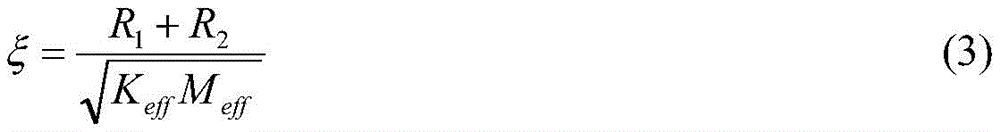

wherein S is0And xi are respectively the static acceleration sensitivity and damping coefficient of the optical fiber acceleration sensing probe, R1And R2Damping of the high damping elastomer and the high damping shock absorber, λ is the laser working wavelength, X is the influence coefficient of the wound optical fiber on the elastic enhancement layer, n and vfRespectively the refractive index and Poisson's ratio of the optical fiber, N the number of turns of the wound optical fiber, v, b and H the Poisson's ratio, the outer radius and the height of the high-damping elastomer, p11And p12Is the elasto-optic coefficient of the fiber.
As shown in FIG. 5, in this embodiment, in order to further illustrate the effect of damping on probe frequency response, the acceleration sensitivity S (f) of the optical fiber acceleration sensing probe is adjusted to be within the damping coefficient ξ And simulating under the scenes of 1, 0.8, 0.6 and 0.4 to obtain a frequency response curve. As shown in fig. 5, when ξ is 1, the resonance of the high-sensitivity optical fiber
 acceleration sensing probe 100 is suppressed, and the resonance peak sensitivity is only 1.155S0The working bandwidth of the optical fiber acceleration sensing probe can be effectively widened.
As shown in FIG. 6, in this example, two different damping systems were measuredThe abscissa of the optical fiber acceleration sensing probe represents the excitation acceleration frequency, the ordinate of the optical fiber acceleration sensing probe represents the actually measured acceleration sensitivity, and as shown in figure 6, when the damping coefficient xi of the sensing probe is 0.8, the actually measured static sensitivity S is obtained0350rad/g, the resonance peak sensitivity is only 1.43S0The resonance frequency is 3000Hz, and the working bandwidth of +/-3 dB can be expanded to 3500 Hz; when the damping coefficient xi of the sensing probe is 0.42, the static sensitivity S is actually measured0325rad/g, resonance peak sensitivity of 2.46S0The resonance frequency is 2700Hz, and the +/-3 dB working bandwidth is less than 2300 Hz. The actual measurement frequency response comparison of the optical fiber acceleration sensing probes with different damping coefficients shows that the damping coefficient of the probe can be adjusted by using different high-damping elastic bodies and high-damping shock absorption bodies to be close to 1, and the high-sensitivity optical fiber acceleration sensing probe with resonance suppression is obtained.
As shown in fig. 1, the present invention further provides an optical fiber microseismic monitoring sensor, which includes: the system comprises a light source module 100, a light transmission module 110, a fiber optic acceleration sensing probe and a microseismic signal demodulation module 120.
As shown in fig. 1, the light source module 100 is configured to output laser light, the light source module 100 is connected to the light transmission module 110, the light transmission module 110 is configured to transmit the laser light emitted from the light source module to other modules of a sensor, the optical fiber acceleration sensing probe is connected to the light transmission module 110, the microseismic signal demodulation module 120 is connected to the light transmission module 110, and the microseismic signal demodulation module 120 is configured to recover a microseismic signal from an interference light signal emitted from the sensing probe, that is, the light transmission module 110 connects the light source module 110, the optical fiber acceleration sensing probe and the microseismic signal demodulation module 120, where a structure of the optical fiber acceleration sensing probe is consistent with a structure of a resonance-suppressed optical fiber acceleration sensing probe provided by the present invention, and no description is given here.
As shown in fig. 1, in this embodiment, the optical transmission module 110 includes a laser input fiber 111, an optical fiber circulator 112, a laser input/output fiber 113, and a signal light output fiber 114, and the laser emitted from the light source module 110 passes through the laser input fiber 111, the optical fiber circulator 112, the laser input/output fiber 113, the optical fiber acceleration sensing probe, the laser input/output fiber 113, the optical fiber circulator 112, and the signal light output fiber 114, and enters the microseismic signal demodulation module 120 to recover the microseismic signal. In this embodiment, the laser input/output fiber 113 extends into the probe housing 10 through the fiber access opening 103 of the probe housing 10 and is connected to the fiber interferometer 50. In this embodiment, the light source module 110 employs a narrow-linewidth single-wavelength laser, and the microseismic signal demodulation module 120 employs one of a phase carrier demodulation scheme and a heterodyne demodulation scheme, for example, in this embodiment, a phase detection scheme.
The invention provides a high-sensitivity optical fiber acceleration sensing probe with resonance suppression, which is characterized in that a probe shell is arranged, the bottom of the probe Kedi is provided with a screw hole, the side edge of the probe is provided with an optical fiber leading-in and leading-out port, one end of a stud is fixed in a threaded hole at the bottom of the shell, a high-damping elastomer is sleeved on the stud and is placed at the bottom of the probe shell, a mass block is placed on the high-damping elastomer, an optical fiber interferometer is arranged in the mass block, a sensing arm is wound on the high-damping elastomer, a reference arm is wound on the mass block, a high-damping shock absorber is placed on the mass block, finally a gasket is placed on the high-damping shock absorber and is fixed through a nut, and the high-damping elastomer, the mass block, the high-damping shock absorber and the gasket are fixed between the, the high-damping elastic body is a transduction unit which converts an acceleration signal into the length change of a wound optical fiber, and is also a shock absorption unit which is matched with the high-damping shock absorption body to control the damping of the probe.
The optical fiber microseismic monitoring sensor provided by the invention recovers microseismic signals through a phase detection technology, has the advantages of high sensitivity, intrinsic safety, electromagnetic interference resistance, strong robustness, large dynamic range and the like, and is suitable for microseismic monitoring in different rock-soil environments such as soft rock, hard rock and the like.
According to the invention, the damping of the probe is optimized through the high-damping material with low Young modulus, the resonance of the probe is inhibited, a flat frequency response curve is obtained while high sensitivity is ensured, the working bandwidth is expanded, so that a microseismic signal with high-precision transient response is ensured to be recovered, accurate seismic source positioning and energy metering are realized, and the method is suitable for monitoring and early warning of various mine dynamic disasters.
In conclusion, the resonance-suppressed high-sensitivity optical fiber acceleration sensing probe disclosed by the invention has the advantages that the high-damping material is introduced to manufacture the elastic body and the shock-absorbing body, so that the damping coefficient of the sensing probe is close to 1, the resonance of the probe is effectively suppressed, and the working bandwidth is expanded; meanwhile, the high-damping material has the characteristic of low Young modulus, and the high-damping elastomer is used as a transducer and a shock absorption body, so that the sensitivity of the probe is greatly improved; in addition, the traditional scheme of injecting silicone oil is avoided, and the requirement on the sealing property of the probe is greatly reduced; the optical fiber micro-seismic monitoring sensor provided by the invention picks up micro-seismic signals by detecting the phase change of laser, has the advantages of high sensitivity, uncharged front end, intrinsic safety, electromagnetic interference resistance, high temperature and high pressure resistance and the like, and is suitable for various micro-seismic monitoring scenes.
The above description is only a preferred embodiment of the present application and the explanation of the technical principle used, and it should be understood by those skilled in the art that the scope of the present application is not limited to the technical solution of the specific combination of the above technical features, and also covers other technical solutions formed by any combination of the above technical features or their equivalent features without departing from the inventive concept, for example, the technical solutions formed by mutually replacing the above technical features (but not limited to) having similar functions disclosed in the present application.
Other technical features than those described in the specification are known to those skilled in the art, and are not described herein in detail in order to highlight the innovative features of the present invention.
Claims (10)
1. A resonance-damped optical fiber acceleration sensing probe, comprising:
the bottom of the probe shell is provided with a screw hole, and the side edge of the probe shell is provided with an optical fiber access;
the double-end stud is arranged in the probe shell, and one end of the double-end stud is connected with the threaded hole;
the high-damping elastic body is sleeved on the stud;
the mass block is sleeved on the stud and is positioned on the high-damping elastomer;
the fiber interferometer is arranged in the mass block and comprises a sensing arm and a reference arm, the sensing arm is wound on the high-damping elastomer, and the reference arm is wound on the mass block;
the high-damping shock absorption body is positioned on the mass block;
the nut sets up stud's the other end, and is located high damping is inhaled and is shaken on the body, just the nut with high damping is inhaled and is provided with the gasket between the shake the body.
2. A resonance suppressed optical fiber acceleration sensing probe according to claim 1, characterized in, that the high damping elastomer is a viscoelastic and arranged as a hollow cylinder.
3. A resonance suppressing optical fiber acceleration sensing probe according to claim 1, characterized in that said high damping shock absorbing body is viscoelastic body and is provided as a hollow circular ring.
4. A resonance suppressed optical fiber acceleration sensing probe according to claim 1, characterized in that said screw hole is located in the middle of the bottom of said probe housing, said mass is a hollow cylinder with grooves on its sides.
5. A resonance suppressed fibre optic acceleration sensing probe according to claim 4, characterized in that the fibre optic interferometer is located in the groove, the reference arm being wound in the groove.
6. A resonance suppressed fibre optic acceleration sensing probe according to claim 4, characterized in that the fibre optic interferometer comprises a fibre optic coupler, a sensing arm, a first fibre optic Faraday rotator mirror, a reference arm and a second fibre optic Faraday rotator mirror.
7. A resonance suppressed fibre optic acceleration sensing probe according to claim 6, characterized in that the fibre optic coupler is connected to the second fibre optic Faraday rotator mirror through the reference arm and the fibre optic coupler is connected to the first fibre optic Faraday rotator mirror through the sensing arm.
8. A resonance damped optical fiber acceleration sensing probe according to claim 6, characterized in that said fiber coupler, first fiber Faraday rotator mirror and second fiber Faraday rotator mirror are located in said groove.
9. A resonance damped optical fiber acceleration sensing probe according to claim 1, characterized by further comprising a housing top cover fixedly arranged on top of said probe housing.
10. A fiber optic microseismic monitoring sensor, wherein the fiber optic microseismic monitoring sensor comprises:
the light source module is used for providing single-wavelength laser;
the light transmission module is connected with the light source module and transmits the laser emitted by the light source module to other modules of the sensor;
the optical fiber acceleration sensing probe is connected with the optical transmission module, and the sensing probe comprises:
the bottom of the probe shell is provided with a screw hole, and the side edge of the probe shell is provided with an optical fiber access;
the double-end stud is arranged in the probe shell, and one end of the double-end stud is connected with the threaded hole;
the high-damping elastic body is sleeved on the stud;
the mass block is sleeved on the stud and is positioned on the high-damping elastomer;
the fiber interferometer is arranged in the mass block and comprises a sensing arm and a reference arm, the sensing arm is wound on the high-damping elastomer, and the reference arm is wound on the mass block;
the high-damping shock absorption body is positioned on the mass block;
the nut is arranged at the other end of the stud and is positioned on the high-damping shock absorption body, and a gasket is arranged between the nut and the high-damping shock absorption body;
and the microseismic signal demodulation module is connected with the optical transmission module and recovers microseismic signals from interference optical signals emitted by the sensing probe.
Priority Applications (2)
| Application Number | Priority Date | Filing Date | Title |
|---|---|---|---|
| CN202011179243.8A CN112379414B (en) | 2020-10-29 | 2020-10-29 | Optical fiber acceleration sensing probe with resonance suppression function and optical fiber microseismic monitoring sensor |
| US17/401,878 US11782071B2 (en) | 2020-10-29 | 2021-08-13 | Optical-fiber-acceleration-sensor probe for suppressing resonance and optical fiber microseismic monitoring sensor |
Applications Claiming Priority (1)
| Application Number | Priority Date | Filing Date | Title |
|---|---|---|---|
| CN202011179243.8A CN112379414B (en) | 2020-10-29 | 2020-10-29 | Optical fiber acceleration sensing probe with resonance suppression function and optical fiber microseismic monitoring sensor |
Publications (2)
| Publication Number | Publication Date |
|---|---|
| CN112379414A true CN112379414A (en) | 2021-02-19 |
| CN112379414B CN112379414B (en) | 2024-02-02 |
Family
ID=74576368
Family Applications (1)
| Application Number | Title | Priority Date | Filing Date |
|---|---|---|---|
| CN202011179243.8A Active CN112379414B (en) | 2020-10-29 | 2020-10-29 | Optical fiber acceleration sensing probe with resonance suppression function and optical fiber microseismic monitoring sensor |
Country Status (2)
| Country | Link |
|---|---|
| US (1) | US11782071B2 (en) |
| CN (1) | CN112379414B (en) |
Citations (12)
| Publication number | Priority date | Publication date | Assignee | Title |
|---|---|---|---|---|
| CN1910430A (en) * | 2004-01-17 | 2007-02-07 | 秦内蒂克有限公司 | Improvements in and relating to accelerometers |
| CN101788569A (en) * | 2009-12-31 | 2010-07-28 | 中国科学院声学研究所 | Optical fiber acceleration transducer probe and acceleration transducer system |
| CN202007466U (en) * | 2011-03-16 | 2011-10-12 | 上海英谷桥梁科技有限公司 | High-dampness rubber viscoelastic damper |
| US20110283795A1 (en) * | 2008-11-19 | 2011-11-24 | The Australian National University | System, Device And Method For Detecting Seismic Acceleration |
| CN102374895A (en) * | 2011-09-26 | 2012-03-14 | 中国人民解放军国防科技大学 | Large dynamic optical fiber vibration sensor |
| CN102576035A (en) * | 2009-10-23 | 2012-07-11 | 美国地震系统有限公司 | Fiber optic transducers, fiber optic accelerometers and fiber optic sensing systems |
| CN208421253U (en) * | 2018-07-05 | 2019-01-22 | 武汉雷施尔光电信息工程有限公司 | A kind of interference-type optical fiber wave detector of anti-Horizonal Disturbing |
| CN109655635A (en) * | 2018-09-01 | 2019-04-19 | 哈尔滨工程大学 | Micro off-axis multiple fiber optic Michelson extrinsic type accelerometer based on Michelson's interferometer |
| CN110244348A (en) * | 2019-06-06 | 2019-09-17 | 山东科技大学 | A photoelectric composite geophone and detection system |
| CN110261895A (en) * | 2019-07-09 | 2019-09-20 | 安徽大学 | A kind of all -fiber Microseismic monitoring system that highly sensitive wideband is rung |
| CN110261893A (en) * | 2019-07-09 | 2019-09-20 | 安徽大学 | A kind of adjustable all -fiber acceleration microseismic monitoring sensor probe of damping |
| CN110646083A (en) * | 2019-10-21 | 2020-01-03 | 安徽大学 | Optical fiber vibration sensing probe, installation method thereof, and optical fiber vibration sensor |
Family Cites Families (16)
| Publication number | Priority date | Publication date | Assignee | Title |
|---|---|---|---|---|
| US4322829A (en) * | 1980-09-11 | 1982-03-30 | Dynamic Systems, Inc. | Fiber optic accelerometer and method of measuring inertial force |
| US4534222A (en) * | 1983-08-08 | 1985-08-13 | Mcdonnell Douglas Corporation | Fiber-optic seismic sensor |
| US4893930A (en) * | 1988-01-25 | 1990-01-16 | The United States Of America As Represented By The Secretary Of The Navy | Multiple axis, fiber optic interferometric seismic sensor |
| US4959539A (en) * | 1989-03-20 | 1990-09-25 | The United States Of America As Represented By The Secretary Of The Navy | Flexural disk fiber optic hydrophone |
| US6496264B1 (en) * | 2000-07-24 | 2002-12-17 | Northrop Grumman Corporation | Fiber optic acoustic sensor with specifically selected flexural disks |
| US6473183B1 (en) * | 2001-05-03 | 2002-10-29 | Northrop Grumman Corporation | Shear damped fiber optic sensor |
| US6650418B2 (en) * | 2001-07-27 | 2003-11-18 | Litton Systems, Inc. | High performance fiber optic accelerometer |
| US7137299B2 (en) * | 2005-04-21 | 2006-11-21 | Northrop Grumman Corporation | Fiber optic accelerometer |
| FR2888339B1 (en) * | 2005-07-07 | 2007-09-21 | Sercel Sa | OPTICAL FIBER SEISMIC SENSOR |
| GB2440351B (en) * | 2006-07-25 | 2008-10-08 | Schlumberger Holdings | Flexural disc fiber optic sensor |
| US7675627B2 (en) * | 2007-10-05 | 2010-03-09 | Northrop Grumman Guidance And Electronic Company, Inc. | Low cost fiber optic velocity sensor for sonar applications |
| US9976351B2 (en) * | 2011-08-05 | 2018-05-22 | Coiled Tubing Specialties, Llc | Downhole hydraulic Jetting Assembly |
| SMT202100529T1 (en) * | 2014-08-06 | 2021-11-12 | Univ Degli Studi Di Salerno | Method for the measurement of angular and/or linear displacements utilizing one or more folded pendula |
| US10545259B2 (en) * | 2016-06-27 | 2020-01-28 | Government Of The United States Of America, As Represented By The Secretary Of Commerce | Optomechanical gravimeter |
| CN209673840U (en) * | 2018-10-09 | 2019-11-22 | 贵阳学院 | A dumbbell slider type fiber optic accelerometer |
| IT202000006703A1 (en) * | 2020-03-31 | 2021-10-01 | Emanuele Giacomozzi | Optical-inertial accelerometer, speckle tracking telesensor using this accelerometer and method of correcting the vibrational noise of this telesensor |
-
2020
- 2020-10-29 CN CN202011179243.8A patent/CN112379414B/en active Active
-
2021
- 2021-08-13 US US17/401,878 patent/US11782071B2/en active Active
Patent Citations (13)
| Publication number | Priority date | Publication date | Assignee | Title |
|---|---|---|---|---|
| CN1910430A (en) * | 2004-01-17 | 2007-02-07 | 秦内蒂克有限公司 | Improvements in and relating to accelerometers |
| US20110283795A1 (en) * | 2008-11-19 | 2011-11-24 | The Australian National University | System, Device And Method For Detecting Seismic Acceleration |
| US20120257208A1 (en) * | 2009-10-23 | 2012-10-11 | James Kengo Andersen | Fiber optic transducers, fiber optic accelerometers and fiber optic sensing systems |
| CN102576035A (en) * | 2009-10-23 | 2012-07-11 | 美国地震系统有限公司 | Fiber optic transducers, fiber optic accelerometers and fiber optic sensing systems |
| CN101788569A (en) * | 2009-12-31 | 2010-07-28 | 中国科学院声学研究所 | Optical fiber acceleration transducer probe and acceleration transducer system |
| CN202007466U (en) * | 2011-03-16 | 2011-10-12 | 上海英谷桥梁科技有限公司 | High-dampness rubber viscoelastic damper |
| CN102374895A (en) * | 2011-09-26 | 2012-03-14 | 中国人民解放军国防科技大学 | Large dynamic optical fiber vibration sensor |
| CN208421253U (en) * | 2018-07-05 | 2019-01-22 | 武汉雷施尔光电信息工程有限公司 | A kind of interference-type optical fiber wave detector of anti-Horizonal Disturbing |
| CN109655635A (en) * | 2018-09-01 | 2019-04-19 | 哈尔滨工程大学 | Micro off-axis multiple fiber optic Michelson extrinsic type accelerometer based on Michelson's interferometer |
| CN110244348A (en) * | 2019-06-06 | 2019-09-17 | 山东科技大学 | A photoelectric composite geophone and detection system |
| CN110261895A (en) * | 2019-07-09 | 2019-09-20 | 安徽大学 | A kind of all -fiber Microseismic monitoring system that highly sensitive wideband is rung |
| CN110261893A (en) * | 2019-07-09 | 2019-09-20 | 安徽大学 | A kind of adjustable all -fiber acceleration microseismic monitoring sensor probe of damping |
| CN110646083A (en) * | 2019-10-21 | 2020-01-03 | 安徽大学 | Optical fiber vibration sensing probe, installation method thereof, and optical fiber vibration sensor |
Non-Patent Citations (2)
| Title |
|---|
| YI D. 等: "光纤地震加速度计瞬态响应的实验研究", 世界地震译丛, vol. 50, no. 4, pages 382 - 389 * |
| 李世丽: "微震监测用光纤加速度传感器研究", 中国优秀博士论文全文数据库, no. 07 * |
Also Published As
| Publication number | Publication date |
|---|---|
| US11782071B2 (en) | 2023-10-10 |
| US20220137087A1 (en) | 2022-05-05 |
| CN112379414B (en) | 2024-02-02 |
Similar Documents
| Publication | Publication Date | Title |
|---|---|---|
| De Freitas | Recent developments in seismic seabed oil reservoir monitoring applications using fibre-optic sensing networks | |
| JP4787367B2 (en) | High sensitivity accelerometer | |
| CN111323613B (en) | Vector optical fiber sensing probe based on optical fiber interferometer and underground vector accelerometer | |
| EP1821107B1 (en) | Pressure compensated optical accelerometer, optical inclinometer and seismic sensor system | |
| CA2436753C (en) | Highly sensitive cross axis accelerometer | |
| US9194738B2 (en) | Fiber optic microseismic sensing systems | |
| Wang et al. | Experimental research of an all-polarization-maintaining optical fiber vector hydrophone | |
| Jiang et al. | All-metal optical fiber accelerometer with low transverse sensitivity for seismic monitoring | |
| US20150308864A1 (en) | Vector Sensor for Seismic Application | |
| CN101907722B (en) | Fiber bragg grating vibration acceleration sensor for monitoring low-frequency earthquake waves | |
| Yang et al. | Seismic observation and analysis based on three-component fiber optic seismometer | |
| CN111397723B (en) | Three-component optical fiber laser micro-vibration sensor with combined structure and application thereof | |
| CN111579050A (en) | Interferometric fiber vector hydrophone with reference interferometer | |
| CN101799555A (en) | Optical fiber ocean bottom seismograph | |
| CN105652312A (en) | Optical fiber geophone system based on distributed optical fiber acoustic sensing technology | |
| CN110261892A (en) | Simple component, three-component optical fiber optical grating vibration transducer and sensor array based on dim light grid | |
| CN106199687A (en) | Simple component geophone | |
| Han et al. | Fiber optic 3-component seismometer | |
| CN112379414A (en) | Optical fiber acceleration sensing probe for resonance suppression and optical fiber microseismic monitoring sensor | |
| Guo et al. | Highly sensitive fiber bragg grating accelerometer with low resonant frequency | |
| Yi et al. | Demonstration of fiber-optic seismic sensor with improved dynamic response in oilfield application | |
| CN212645880U (en) | Interferometric fiber vector hydrophone with reference interferometer | |
| CN114488278B (en) | Fiber bragg grating seismic wave acceleration vector detector | |
| RU2231088C1 (en) | Hydrophone | |
| CN114814933B (en) | Fiber Bragg Grating Seismic Acceleration Vector Detector with Temperature Compensation Function |
Legal Events
| Date | Code | Title | Description |
|---|---|---|---|
| PB01 | Publication | ||
| PB01 | Publication | ||
| SE01 | Entry into force of request for substantive examination | ||
| SE01 | Entry into force of request for substantive examination | ||
| GR01 | Patent grant | ||
| GR01 | Patent grant |