CN112003385A - Single-transmitting multi-receiving wireless charging device - Google Patents
Single-transmitting multi-receiving wireless charging device Download PDFInfo
- Publication number
- CN112003385A CN112003385A CN202010303583.0A CN202010303583A CN112003385A CN 112003385 A CN112003385 A CN 112003385A CN 202010303583 A CN202010303583 A CN 202010303583A CN 112003385 A CN112003385 A CN 112003385A
- Authority
- CN
- China
- Prior art keywords
- receiving
- transmitting
- coil group
- wireless charging
- charging device
- Prior art date
- Legal status (The legal status is an assumption and is not a legal conclusion. Google has not performed a legal analysis and makes no representation as to the accuracy of the status listed.)
- Granted
Links
Images


Classifications
-
- H—ELECTRICITY
- H02—GENERATION; CONVERSION OR DISTRIBUTION OF ELECTRIC POWER
- H02J—CIRCUIT ARRANGEMENTS OR SYSTEMS FOR SUPPLYING OR DISTRIBUTING ELECTRIC POWER; SYSTEMS FOR STORING ELECTRIC ENERGY
- H02J50/00—Circuit arrangements or systems for wireless supply or distribution of electric power
- H02J50/10—Circuit arrangements or systems for wireless supply or distribution of electric power using inductive coupling
-
- H—ELECTRICITY
- H02—GENERATION; CONVERSION OR DISTRIBUTION OF ELECTRIC POWER
- H02J—CIRCUIT ARRANGEMENTS OR SYSTEMS FOR SUPPLYING OR DISTRIBUTING ELECTRIC POWER; SYSTEMS FOR STORING ELECTRIC ENERGY
- H02J50/00—Circuit arrangements or systems for wireless supply or distribution of electric power
- H02J50/40—Circuit arrangements or systems for wireless supply or distribution of electric power using two or more transmitting or receiving devices
Landscapes
- Engineering & Computer Science (AREA)
- Computer Networks & Wireless Communication (AREA)
- Power Engineering (AREA)
- Charge And Discharge Circuits For Batteries Or The Like (AREA)
Abstract
本发明公开了一种单发多收无线充电装置,包括,发射单元,包括供源件逆变器和单发件,所述供源件通过逆变器与所述单发件建立连接;以及,接收单元,与所述单发件配合;所述单发件包括第一线圈组和第二线圈组,所述第一线圈组一端与第二线圈组一端串联连接;其中,所述第一线圈组另一端和第二线圈组另一端均与所述逆变器连接;本发明通过设置的发射单元和接收单元之间相互配合,利用磁感应耦合的方式实现了对多个负载的一对多无线充电,且单发件采用上下对称的线圈串联而成,增大有效交变磁场的面积,提高了抗偏移能力。
The invention discloses a single-transmitting multiple-receiving wireless charging device, comprising a transmitting unit, including a source-supplying part inverter and a single-transmitting part, wherein the supplying part establishes a connection with the single-transmitting part through an inverter; and , a receiving unit matched with the single-transmitting component; the single-transmitting component includes a first coil group and a second coil group, one end of the first coil group is connected in series with one end of the second coil group; wherein, the first coil group The other end of the coil group and the other end of the second coil group are both connected to the inverter; the present invention realizes the one-to-many connection of multiple loads by means of magnetic induction coupling through the mutual cooperation between the transmitting unit and the receiving unit. Wireless charging, and the single transmitter is made of upper and lower symmetrical coils in series, which increases the area of the effective alternating magnetic field and improves the anti-offset ability.
Description
技术领域technical field
本发明涉及的无线电能传输技术领域,尤其涉及一种单发多收无线充电装置。The present invention relates to the technical field of wireless power transmission, and in particular, to a single-transmit and multiple-receive wireless charging device.
背景技术Background technique
传统的感应耦合式无线充电装置基于电磁感应原理,利用松耦合变压器实现电能的无线传输,松耦合变压器的发射线圈和接收线圈间的气隙较常规变压器要大得多,漏感大,传输效率和传输功率比较低,抗偏移能力也比较差;且传统的感应耦合式装置只能实现对单个负载的一对一充电。The traditional inductively coupled wireless charging device is based on the principle of electromagnetic induction, and uses a loosely coupled transformer to realize wireless transmission of power. And the transmission power is relatively low, and the anti-offset ability is relatively poor; and the traditional inductive coupling device can only achieve one-to-one charging for a single load.
发明内容SUMMARY OF THE INVENTION
本部分的目的在于概述本发明的实施例的一些方面以及简要介绍一些较佳实施例。在本部分以及本申请的说明书摘要和发明名称中可能会做些简化或省略以避免使本部分、说明书摘要和发明名称的目的模糊,而这种简化或省略不能用于限制本发明的范围。The purpose of this section is to outline some aspects of embodiments of the invention and to briefly introduce some preferred embodiments. Some simplifications or omissions may be made in this section and the abstract and title of the application to avoid obscuring the purpose of this section, abstract and title, and such simplifications or omissions may not be used to limit the scope of the invention.
鉴于上述现有单发多收无线充电装置存在的抗偏移能力差问题,提出了本发明。In view of the problem of poor anti-offset capability of the existing single-transmit-multiple-receive wireless charging devices mentioned above, the present invention is proposed.
因此,本发明目的是提供一种单发多收无线充电装置。Therefore, the purpose of the present invention is to provide a single-transmit multiple-receive wireless charging device.
为解决上述技术问题,本发明提供如下技术方案:一种单发多收无线充电装置,包括,In order to solve the above technical problems, the present invention provides the following technical solutions: a single-transmitting multiple-receiving wireless charging device, comprising:
发射单元,包括供源件逆变器和单发件,所述供源件通过逆变器与所述单发件建立连接;以及,a transmitting unit, including an inverter for a power supply element and a single-emitting element, the supplying element establishing a connection with the single-emitting element through an inverter; and,
接收单元,与所述单发件配合。a receiving unit, matched with the single-send piece.
作为本发明所述单发多收无线充电装置的一种优选方案,其中:所述单发件包括第一线圈组和第二线圈组,所述第一线圈组一端与第二线圈组一端串联连接;As a preferred solution of the single-transmitting-multiple-receiving wireless charging device of the present invention, wherein: the single-transmitting component includes a first coil group and a second coil group, and one end of the first coil group is connected in series with one end of the second coil group connect;
其中,所述第一线圈组另一端和第二线圈组另一端均与所述逆变器连接。Wherein, the other end of the first coil group and the other end of the second coil group are both connected to the inverter.
作为本发明所述单发多收无线充电装置的一种优选方案,其中:所述第一线圈组至少设置有两个发射线圈,两个所述发射线圈串联连接。As a preferred solution of the single-transmitting-multiple-receiving wireless charging device of the present invention, the first coil group is provided with at least two transmitting coils, and the two transmitting coils are connected in series.
作为本发明所述单发多收无线充电装置的一种优选方案,其中:两个所述发射线圈-结构相同且采用利兹线绕制成正方形形状。As a preferred solution of the single-transmitting-multiple-receiving wireless charging device of the present invention, the two transmitting coils have the same structure and are wound into a square shape with Litz wire.
作为本发明所述单发多收无线充电装置的一种优选方案,其中:所述第一线圈组与第二线圈组结构相同且平行对称设置。As a preferred solution of the single-transmitting-multiple-receiving wireless charging device of the present invention, the first coil group and the second coil group have the same structure and are arranged symmetrically in parallel.
作为本发明所述单发多收无线充电装置的一种优选方案,其中:所述单发件还包括发射电阻和发射补偿电容,所述发射电阻、发射补偿电容、第一线圈组和第二线圈组之间串联。As a preferred solution of the single-transmitting-multiple-receiving wireless charging device of the present invention, wherein: the single-transmitting element further includes a transmitting resistance and a transmitting compensation capacitor, the transmitting resistance, the transmitting compensation capacitance, the first coil group and the second The coils are connected in series.
作为本发明所述单发多收无线充电装置的一种优选方案,其中:所述接收单元包括接收线圈和负载,所述接收线圈与负载连接;As a preferred solution of the single-transmit and multiple-receive wireless charging device of the present invention, wherein: the receiving unit includes a receiving coil and a load, and the receiving coil is connected to the load;
其中,所述接收线圈和负载均至少设置有二个,二个所述接收线圈分别与二个所述负载对应连接。Wherein, there are at least two receiving coils and loads, and the two receiving coils are respectively connected to the two loads correspondingly.
作为本发明所述单发多收无线充电装置的一种优选方案,其中:所述接收线圈采用利兹线绕制。As a preferred solution of the single-transmitting-multiple-receiving wireless charging device of the present invention, wherein: the receiving coil is wound with a Litz wire.
作为本发明所述单发多收无线充电装置的一种优选方案,其中:所述接收单元还包括接收补偿电容和接收电阻,所述接收补偿电容、接收电阻、接收线圈和负载之间串联连接。As a preferred solution of the single-transmit and multiple-receive wireless charging device of the present invention, wherein: the receiving unit further includes a receiving compensation capacitor and a receiving resistance, and the receiving compensation capacitance, the receiving resistance, the receiving coil and the load are connected in series .
作为本发明所述单发多收无线充电装置的一种优选方案,其中:。As a preferred solution of the single-transmitting-multiple-receiving wireless charging device of the present invention, wherein: .
本发明的有益效果:本发明通过设置的发射单元和接收单元之间相互配合,利用磁感应耦合的方式实现了对多个负载的一对多无线充电,且单发件采用上下对称的线圈串联而成,增大有效交变磁场的面积,提高了抗偏移能力。Beneficial effects of the present invention: the present invention realizes one-to-many wireless charging for multiple loads by means of magnetic induction coupling through the mutual cooperation between the set transmitting unit and receiving unit, and the single-transmitting unit adopts upper and lower symmetrical coils in series to connect It can increase the area of the effective alternating magnetic field and improve the anti-offset ability.
附图说明Description of drawings
为了更清楚地说明本发明实施例的技术方案,下面将对实施例描述中所需要使用的附图作简单地介绍,显而易见地,下面描述中的附图仅仅是本发明的一些实施例,对于本领域普通技术人员来讲,在不付出创造性劳动性的前提下,还可以根据这些附图获得其它的附图。其中:In order to illustrate the technical solutions of the embodiments of the present invention more clearly, the following briefly introduces the accompanying drawings used in the description of the embodiments. Obviously, the drawings in the following description are only some embodiments of the present invention. For those of ordinary skill in the art, other drawings can also be obtained based on these drawings without any creative effort. in:
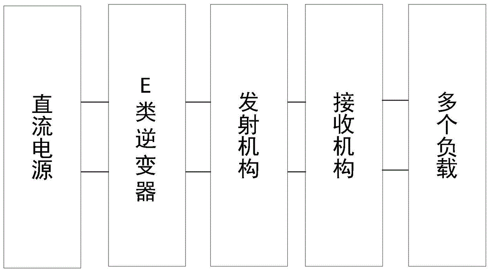
图1为本发明单发多收无线充电装置的结构框图。FIG. 1 is a structural block diagram of a single-transmitting-multiple-receiving wireless charging device according to the present invention.
图2为本发明单发多收无线充电装置的充电原理图示意图。FIG. 2 is a schematic diagram of the charging principle of the single-transmitting-multiple-receiving wireless charging device of the present invention.
图3为本发明单发多收无线充电装置的发射线圈结构示意图。FIG. 3 is a schematic structural diagram of the transmitting coil of the single-transmitting-multiple-receiving wireless charging device of the present invention.
图4(a)~(m)为本发明单发多收无线充电装置的左侧负载测试示意图。4(a)-(m) are schematic diagrams of the load test on the left side of the single-transmit-multiple-receive wireless charging device of the present invention.
图5(a)~(l)为本发明单发多收无线充电装置的中间负载测试示意图。5(a)-(l) are schematic diagrams of intermediate load testing of the single-transmitting-multiple-receiving wireless charging device of the present invention.
图6(a)~(l)为本发明单发多收无线充电装置的右侧负载测试示意图。6(a)-(l) are schematic diagrams of the load test on the right side of the single-transmitting-multiple-receiving wireless charging device of the present invention.
图7(a)~(m)为本发明单发多收无线充电装置的A组实验测试示意图。7(a)-(m) are schematic diagrams of group A experimental tests of the single-transmit-multiple-receive wireless charging device of the present invention.
图8(a)~(f)为本发明单发多收无线充电装置的B组实验测试示意图。8(a)-(f) are schematic diagrams of group B experimental tests of the single-transmitting-multiple-receiving wireless charging device of the present invention.
具体实施方式Detailed ways
为使本发明的上述目的、特征和优点能够更加明显易懂,下面结合说明书附图对本发明的具体实施方式做详细的说明。In order to make the above objects, features and advantages of the present invention more clearly understood, the specific embodiments of the present invention will be described in detail below with reference to the accompanying drawings.
在下面的描述中阐述了很多具体细节以便于充分理解本发明,但是本发明还可以采用其他不同于在此描述的其它方式来实施,本领域技术人员可以在不违背本发明内涵的情况下做类似推广,因此本发明不受下面公开的具体实施例的限制。Many specific details are set forth in the following description to facilitate a full understanding of the present invention, but the present invention can also be implemented in other ways different from those described herein, and those skilled in the art can do so without departing from the connotation of the present invention. Similar promotion, therefore, the present invention is not limited by the specific embodiments disclosed below.
其次,此处所称的“一个实施例”或“实施例”是指可包含于本发明至少一个实现方式中的特定特征、结构或特性。在本说明书中不同地方出现的“在一个实施例中”并非均指同一个实施例,也不是单独的或选择性的与其他实施例互相排斥的实施例。Second, reference herein to "one embodiment" or "an embodiment" refers to a particular feature, structure, or characteristic that may be included in at least one implementation of the present invention. The appearances of "in one embodiment" in various places in this specification are not all referring to the same embodiment, nor are they separate or selectively mutually exclusive from other embodiments.
再其次,本发明结合示意图进行详细描述,在详述本发明实施例时,为便于说明,表示器件结构的剖面图会不依一般比例作局部放大,而且所述示意图只是示例,其在此不应限制本发明保护的范围。此外,在实际制作中应包含长度、宽度及深度的三维空间尺寸。Thirdly, the present invention is described in detail with reference to the schematic diagrams. When describing the embodiments of the present invention in detail, for the convenience of explanation, the cross-sectional views showing the device structure will not be partially enlarged according to the general scale, and the schematic diagrams are only examples, which should not be used here. Limit the scope of protection of the present invention. In addition, the three-dimensional spatial dimensions of length, width and depth should be included in the actual production.
实施例1Example 1
参照图1,提供了一种单发多收无线充电装置的整体结构示意图,如图1,一种单发多收无线充电装置包括发射单元100,包括供源件101逆变器102和单发件103,供源件101通过逆变器102与单发件103建立连接;以及,接收单元 200,与单发件103配合。Referring to FIG. 1 , a schematic diagram of the overall structure of a single-transmit-multiple-receive wireless charging device is provided. As shown in FIG. 1 , a single-transmission-multiple-receiver wireless charging device includes a
具体的,本发明主体结构包括发射单元100和接收单元200,通过设置的发射单元100和接收单元200之间相互配合,利用磁感应耦合的方式实现了对多个负载的一对多无线充电,且单发件采用上下对称的线圈串联而成,扩大了发射面积,提高了抗偏移能力,其中,发射单元100,提供了发射的电源,为无线充电提供了充电的条件,其包括供源件101、逆变器102和单发件103,供源件101 通过逆变器102与单发件103建立连接;以及,接收单元200,用于接收发射单元100发射的电能供充电负载,与单发件103配合,发射单元100发射电能耦合入接收单元200中的多个接收线圈中,再传递电能到与之相连的负载。Specifically, the main structure of the present invention includes a
需说明,供源件101为本无线充电装置提供了初级电能,其能够提供直流电源,供源件101为蓄电池或干电池等,其逆变器102起到直交转换的作用,本实施例中,逆变器102用于将供源件101的直流电能逆变为高频交流电能,为单发件供电,优选的,逆变器102为E类逆变器,E类逆变器单开关管逆变电路,拓扑结构简单,器件使用少,能降低逆变设备成本;同时,由于单开关管的拓扑,其开关损耗较小;在理想软开关状态,E类逆变器理论效率可达100%;其具备高频、高效及高功率的特性,采用单开管结构,时控要求低特性。It should be noted that the
进一步的,单发件103包括第一线圈组103a和第二线圈组103b,第一线圈组103a一端与第二线圈组103b一端串联连接;其中,第一线圈组103a另一端和第二线圈组103b另一端均与逆变器102连接;需说明,第一线圈组103a至少设置有两个发射线圈103a-1,两个发射线圈103a-1串联连接,两个发射线圈103a-1 结构相同且采用利兹线绕制成正方形形状。Further, the
较好的,单发件103还包括发射电阻103c和发射补偿电容103d,发射补偿电容103d用以补偿无功,减少无功功率带来的有功功率损耗,其发射电阻103c、发射补偿电容103d、第一线圈组103a和第二线圈组103b之间串联。Preferably, the
进一步的,第一线圈组103a与第二线圈组103b结构相同且平行对称设置,优选的,第一线圈组103a与第二线圈组103b均设置有7个发射线圈,14个小线圈(两排平行放置,上7下7)串联而成,采用利兹线绕制,采用利兹线可以增大导线表面积,从而减小高频交流电流过导体时的交流阻抗,降低线圈的损耗,提高系统效率,如图3所示,具体的,利兹线从外向内成正方形绕制,绕到最内一层形成第一个正方形后,利兹线向初头方向抽出到最外圈后向右走,在第一个正方形右边从外向内进行第二个正方形绕制,如此循环往复直到形成7个正方形一排,然后在第一排的下方用同样的方法绕制7个正方形小线圈,两排的最后一个线圈的尾线头相互连接起来,上下两排的线圈结构大小相等,且上下互相对称;单发件的14个发射线圈(两排平行放置,上7下7)串联,扩大了发射面积,提高了抗偏移能力。Further, the
实施例2Example 2
参照图2,该实施例不同于第一个实施例的是:接收单元200包括接收线圈 201、负载202、接收补偿电容203和接收电阻204,通过设置的接收线圈201、负载202、接收补偿电容203和接收电阻204之间相互配合,能够实现稳定接收充电。具体的,接收单元200包括接收线圈201和负载202,接收线圈201与负载202连接;其中,接收线圈201和负载202均至少设置有二个,二个接收线圈 201分别与二个负载202对应连接,需说明,负载为灯泡或蓄电池等。2, this embodiment is different from the first embodiment in that the receiving
进一步的,接收单元200还包括接收补偿电容203和接收电阻204,其中,接收补偿电容203、接收电阻204、接收线圈201和负载202之间串联连接。Further, the receiving
需说明,接收线圈201采用利兹线绕制,利兹线从外向内成正方形绕制,然后向初头方向抽出到最外圈,首尾两端分别串联负载和补偿电容。It should be noted that the receiving
实施例3Example 3
对本装置法中采用的技术效果加以验证说明,以科学论证的手段对比试验结果,以验证本装置所具有的真实效果。The technical effect adopted in the device method is verified and explained, and the test results are compared by means of scientific demonstration to verify the real effect of the device.
传统的技术方案:存在抗偏移能力差问题,为验证本方法相对传统方法具有抗偏移能力好,同时能够实现单发多收稳定性能高等效果。The traditional technical solution: there is a problem of poor anti-migration ability. In order to verify that this method has better anti-migration ability than the traditional method, and can achieve the effect of high stability of single-transmission and multiple-reception.
本实施例中将采用传统单发单收A以及单发多收B(单发线圈采用矩形螺旋线圈,逆变器采用全桥逆变器)和本装置单发多收分别对进行实时测量抗偏移能力好,同时能够实现单发多收稳定性能高对比。In this embodiment, the traditional single-transmit single-receiver A and single-transmission-multiple-receive B (the single-transmission coil adopts a rectangular spiral coil, and the inverter adopts a full-bridge inverter) and the device single-transmission-multiple-receiver are used for real-time measurement resistance respectively. The offset ability is good, and at the same time, it can achieve high contrast of single-transmit and multiple-receive stability performance.
测试环境:在上海大学杨浦校区实验室内搭建传统单发单收A(单发线圈采用矩形螺旋线圈,逆变器采用全桥逆变器)以及单发多收B(单发线圈采用矩形螺旋线圈,逆变器采用全桥逆变器)以及按照本装置单发多收(单发线圈上下对称设置且均采用利兹线绕制,逆变器采用E类逆变器)结构,实验设备还包括负载(蓄电池或灯泡)等。Test environment: In the laboratory of Shanghai University's Yangpu campus, the traditional single-transmitting and single-receiving A (the single-transmitting coil adopts a rectangular spiral coil, and the inverter adopts a full-bridge inverter) and the single-transmitting and multiple-receiving B (the single-transmitting coil adopts a rectangular spiral The coil, the inverter adopts the full-bridge inverter) and the single-transmitting and multiple-receiving according to the device (the single-transmitting coil is arranged symmetrically up and down and is wound with Litz wire, and the inverter adopts the E-class inverter) structure, and the experimental equipment is also Including loads (batteries or bulbs), etc.
进一步的,此次实验,本装置采用单发三收,发射线圈长102cm,宽25.5cm,由14个自感为9uH,长宽为11cm,6匝,利兹线,小线圈串联而成,负载为两个灯泡负载和一个蓄电池负载,三接收线圈线圈外圈为11匝,内圈为6匝,自感为80hH。Further, in this experiment, the device adopts single transmitter and three receivers. The transmitter coil is 102cm long and 25.5cm wide. It consists of 14 self-inductances of 9uH, length and width of 11cm, 6 turns, Litz wire, and small coils connected in series. For two bulb loads and one battery load, the outer circle of the three receiving coils is 11 turns, the inner circle is 6 turns, and the self-inductance is 80hH.
测量过程:本装置实验采用一对多线圈,实验中,分别将蓄电池负载置于线圈左,中,右三个位置,同时在每个位置在负载距离线圈3-14cm时,记录样机输入电压电流及输出电压电流;传统单发单收A方案实验采用一对一线圈,如图7和8,实验中,将蓄电池负载置于发射线圈正中位置,在负载距离线圈 3-15cm时,记录样机输入电压电流及输出电压电流;传统单发单收A方案采用一对多线圈,实验中,将蓄电池负载置于发射线圈正中位置,在负载距离线圈 3-15cm时,记录样机输入电压电流及输出电压电流。Measurement process: The experiment of this device adopts one-to-many coils. In the experiment, the battery load is placed in the left, middle and right positions of the coil, and the input voltage and current of the prototype are recorded when the load is 3-14cm away from the coil at each position. and output voltage and current; the traditional single-transmitting-single-receiver A scheme experiment uses one-to-one coils, as shown in Figures 7 and 8. In the experiment, the battery load is placed in the center of the transmitting coil, and the input of the prototype is recorded when the load is 3-15cm away from the coil. Voltage, current and output voltage and current; the traditional single-transmitting, single-receiving A scheme uses one-to-many coils. In the experiment, the battery load is placed in the middle of the transmitting coil, and the input voltage, current and output voltage of the prototype are recorded when the load is 3-15cm away from the coil. current.
测量结果如图4(a)~(m)到8(a)~(f),能够了解到:传统方案A组实验中,在负载与线圈距离由远到近变化时,由于耦合强度增强,其等效负载变化,此时由于等效负载变化,在距离变近时,输出功率先上升再下降,同时,开关管工作于硬开关状态;所以,通过实验可得,采用单对单螺旋线圈时,接收线圈变近,E类逆变器无法工作在软开关状态,并且采用一对一线圈,当接收端放置单台负载时,若负载偏离发射线圈的中心位置,接收设备的接收功率将急剧下降;The measurement results are shown in Figures 4(a)~(m) to 8(a)~(f). It can be seen that: in the experiment of the traditional scheme group A, when the distance between the load and the coil changes from far to near, due to the enhanced coupling strength, The equivalent load changes. At this time, due to the change of the equivalent load, when the distance becomes closer, the output power first rises and then falls. At the same time, the switch tube works in a hard switching state; therefore, it can be obtained through experiments that a single pair of single spiral coils are used When the receiving coil gets closer, the E-type inverter cannot work in the soft switching state, and uses one-to-one coils. When a single load is placed at the receiving end, if the load deviates from the center of the transmitting coil, the receiving power of the receiving device will be reduced. A sharp decline;
传统方案B组实验中对应三台负载,除中间位置的负载能正常接收外,另两台负载接收功率均极低,无法对接收设备进行充电,同样,若三台负载都靠近发射线圈时,逆变器将工作在硬开关状态;The traditional scheme group B experiment corresponds to three loads. Except the load in the middle position can receive normally, the receiving power of the other two loads is extremely low and cannot charge the receiving device. Similarly, if the three loads are close to the transmitting coil, The inverter will work in a hard switching state;
本装置在负载与线距离由近到远变化时,由于耦合强度减弱,其等效负载减小;所以,通过实验可得,无论在线圈的那个位置,在较大的负载变化范围内,E类逆变器均能工作在软开关状态,使其抗偏移能力大大优于传统方案A 组和B组,如此保证了单发多收稳定性能。When the distance between the load and the line changes from near to far, the equivalent load of the device decreases due to the weakening of the coupling strength; therefore, it can be obtained through experiments that no matter where the coil is located, within a large load variation range, E All types of inverters can work in a soft-switching state, making their anti-offset capability much better than those of traditional solutions in Group A and Group B, thus ensuring the stable performance of single-transmit and multiple-receive.
重要的是,应注意,在多个不同示例性实施方案中示出的本申请的构造和布置仅是例示性的。尽管在此公开内容中仅详细描述了几个实施方案,但参阅此公开内容的人员应容易理解,在实质上不偏离该申请中所描述的主题的新颖教导和优点的前提下,许多改型是可能的(例如,各种元件的尺寸、尺度、结构、形状和比例、以及参数值(例如,温度、压力等)、安装布置、材料的使用、颜色、定向的变化等)。例如,示出为整体成形的元件可以由多个部分或元件构成,元件的位置可被倒置或以其它方式改变,并且分立元件的性质或数目或位置可被更改或改变。因此,所有这样的改型旨在被包含在本发明的范围内。可以根据替代的实施方案改变或重新排序任何过程或方法步骤的次序或顺序。在权利要求中,任何“装置加功能”的条款都旨在覆盖在本文中所描述的执行所述功能的结构,且不仅是结构等同而且还是等同结构。在不背离本发明的范围的前提下,可以在示例性实施方案的设计、运行状况和布置中做出其他替换、改型、改变和省略。因此,本发明不限制于特定的实施方案,而是扩展至仍落在所附的权利要求书的范围内的多种改型。It is important to note that the construction and arrangement of the present application shown in the various exemplary embodiments are merely exemplary. Although only a few embodiments have been described in detail in this disclosure, those who refer to this disclosure will readily appreciate that many modifications are possible without materially departing from the novel teachings and advantages of the subject matter described in this application are possible (eg, changes in size, dimensions, structure, shape, and proportions of various elements, as well as parameter values (eg, temperature, pressure, etc.), mounting arrangement, use of materials, color, orientation, etc.). For example, elements shown as integrally formed may be constructed of multiple parts or elements, the positions of elements may be inverted or otherwise varied, and the nature or number or positions of discrete elements may be altered or varied. Accordingly, all such modifications are intended to be included within the scope of this invention. The order or sequence of any process or method steps may be varied or re-sequenced according to alternative embodiments. In the claims, any "mean-plus-function" clause is intended to cover the structures described herein as performing the recited function and not only structural equivalents but also equivalent structures. Other substitutions, modifications, changes and omissions may be made in the design, operation and arrangement of the exemplary embodiments without departing from the scope of the present invention. Therefore, the present invention is not limited to a particular embodiment, but extends to various modifications still falling within the scope of the appended claims.
此外,为了提供示例性实施方案的简练描述,可以不描述实际实施方案的所有特征(即,与当前考虑的执行本发明的最佳模式不相关的那些特征,或于实现本发明不相关的那些特征)。Furthermore, in order to provide a concise description of example embodiments, all features of an actual implementation (ie, those that are not relevant to the best mode currently considered for carrying out the invention, or those that are not relevant for carrying out the invention, may not be described in order to provide a concise description of example embodiments) feature).
应理解的是,在任何实际实施方式的开发过程中,如在任何工程或设计项目中,可做出大量的具体实施方式决定。这样的开发努力可能是复杂的且耗时的,但对于那些得益于此公开内容的普通技术人员来说,不需要过多实验,所述开发努力将是一个设计、制造和生产的常规工作。It should be appreciated that during the development of any actual implementation, such as in any engineering or design project, numerous implementation-specific decisions may be made. Such a development effort may be complex and time-consuming, but would be a routine undertaking of design, fabrication, and production without undue experimentation for those of ordinary skill having the benefit of this disclosure .
应说明的是,以上实施例仅用以说明本发明的技术方案而非限制,尽管参照较佳实施例对本发明进行了详细说明,本领域的普通技术人员应当理解,可以对本发明的技术方案进行修改或者等同替换,而不脱离本发明技术方案的精神和范围,其均应涵盖在本发明的权利要求范围当中。It should be noted that the above embodiments are only used to illustrate the technical solutions of the present invention and not to limit them. Although the present invention has been described in detail with reference to the preferred embodiments, those of ordinary skill in the art should understand that the technical solutions of the present invention can be Modifications or equivalent substitutions without departing from the spirit and scope of the technical solutions of the present invention should be included in the scope of the claims of the present invention.
Claims (9)
Priority Applications (1)
| Application Number | Priority Date | Filing Date | Title |
|---|---|---|---|
| CN202010303583.0A CN112003385B (en) | 2020-04-17 | 2020-04-17 | A single-transmitter and multi-receiver wireless charging device |
Applications Claiming Priority (1)
| Application Number | Priority Date | Filing Date | Title |
|---|---|---|---|
| CN202010303583.0A CN112003385B (en) | 2020-04-17 | 2020-04-17 | A single-transmitter and multi-receiver wireless charging device |
Publications (2)
| Publication Number | Publication Date |
|---|---|
| CN112003385A true CN112003385A (en) | 2020-11-27 |
| CN112003385B CN112003385B (en) | 2023-09-19 |
Family
ID=73461450
Family Applications (1)
| Application Number | Title | Priority Date | Filing Date |
|---|---|---|---|
| CN202010303583.0A Active CN112003385B (en) | 2020-04-17 | 2020-04-17 | A single-transmitter and multi-receiver wireless charging device |
Country Status (1)
| Country | Link |
|---|---|
| CN (1) | CN112003385B (en) |
Cited By (14)
| Publication number | Priority date | Publication date | Assignee | Title |
|---|---|---|---|---|
| CN112751397A (en) * | 2020-12-29 | 2021-05-04 | 东北林业大学 | Strong anti-offset wireless charging system for cooperative power supply of desktop display and smart phone |
| US20230134091A1 (en) * | 2021-11-03 | 2023-05-04 | Nucurrent, Inc. | Wireless Power Transmission Antenna with Antenna Molecules |
| US11824373B2 (en) | 2021-11-03 | 2023-11-21 | Nucurrent, Inc. | Wireless power transmission antenna with parallel coil molecule configuration |
| US11824371B2 (en) | 2021-11-03 | 2023-11-21 | Nucurrent, Inc. | Wireless power transmission antenna with internal repeater and repeater filter |
| US11824372B2 (en) | 2021-11-03 | 2023-11-21 | Nucurrent, Inc. | Wireless power transmission antenna with puzzled antenna molecules |
| US11831173B2 (en) | 2021-11-03 | 2023-11-28 | Nucurrent, Inc. | Wireless power transmission antenna with series coil molecule configuration |
| US11831176B2 (en) | 2021-11-03 | 2023-11-28 | Nucurrent, Inc. | Wireless power transfer systems with substantial uniformity over a large area |
| US11831177B2 (en) | 2021-11-03 | 2023-11-28 | Nucurrent, Inc. | Wireless power transmitter with internal repeater and enhanced uniformity |
| US11848566B2 (en) | 2021-11-03 | 2023-12-19 | Nucurrent, Inc. | Dual communications demodulation of a wireless power transmission system having an internal repeater |
| US11862991B2 (en) | 2021-11-03 | 2024-01-02 | Nucurrent, Inc. | Wireless power transmission antenna with internal repeater and in-coil tuning |
| US11862984B2 (en) | 2021-11-03 | 2024-01-02 | Nucurrent, Inc. | Wireless power receiver with repeater for enhanced power harvesting |
| US11962337B2 (en) | 2021-11-03 | 2024-04-16 | Nucurrent, Inc. | Communications demodulation in wireless power transmission system having an internal repeater |
| US12027880B2 (en) | 2021-11-03 | 2024-07-02 | Nucurrent, Inc. | Wireless power transfer from mouse pad to mouse |
| US12549034B2 (en) | 2024-06-26 | 2026-02-10 | Nucurrent, Inc. | Large area wireless power transfer system |
Citations (5)
| Publication number | Priority date | Publication date | Assignee | Title |
|---|---|---|---|---|
| CN103138408A (en) * | 2013-02-27 | 2013-06-05 | 东南大学 | Single-transmission and multiple-receiving type wireless energy transmission device |
| CN203193402U (en) * | 2013-02-27 | 2013-09-11 | 东南大学 | A single-send-multiple-receive wireless energy transmission device |
| KR20160049130A (en) * | 2014-10-24 | 2016-05-09 | 한국철도기술연구원 | Wireless power transfer device with large airgap for power supply |
| CN109245231A (en) * | 2018-10-29 | 2019-01-18 | 浙江大学 | A kind of wireless charging topological structure with nature constant pressure and flow output characteristics |
| KR20190063930A (en) * | 2017-11-30 | 2019-06-10 | 엘지이노텍 주식회사 | Wireless Charging Apparatus and System |
-
2020
- 2020-04-17 CN CN202010303583.0A patent/CN112003385B/en active Active
Patent Citations (5)
| Publication number | Priority date | Publication date | Assignee | Title |
|---|---|---|---|---|
| CN103138408A (en) * | 2013-02-27 | 2013-06-05 | 东南大学 | Single-transmission and multiple-receiving type wireless energy transmission device |
| CN203193402U (en) * | 2013-02-27 | 2013-09-11 | 东南大学 | A single-send-multiple-receive wireless energy transmission device |
| KR20160049130A (en) * | 2014-10-24 | 2016-05-09 | 한국철도기술연구원 | Wireless power transfer device with large airgap for power supply |
| KR20190063930A (en) * | 2017-11-30 | 2019-06-10 | 엘지이노텍 주식회사 | Wireless Charging Apparatus and System |
| CN109245231A (en) * | 2018-10-29 | 2019-01-18 | 浙江大学 | A kind of wireless charging topological structure with nature constant pressure and flow output characteristics |
Cited By (15)
| Publication number | Priority date | Publication date | Assignee | Title |
|---|---|---|---|---|
| CN112751397A (en) * | 2020-12-29 | 2021-05-04 | 东北林业大学 | Strong anti-offset wireless charging system for cooperative power supply of desktop display and smart phone |
| US20230134091A1 (en) * | 2021-11-03 | 2023-05-04 | Nucurrent, Inc. | Wireless Power Transmission Antenna with Antenna Molecules |
| US11824373B2 (en) | 2021-11-03 | 2023-11-21 | Nucurrent, Inc. | Wireless power transmission antenna with parallel coil molecule configuration |
| US11824371B2 (en) | 2021-11-03 | 2023-11-21 | Nucurrent, Inc. | Wireless power transmission antenna with internal repeater and repeater filter |
| US11824372B2 (en) | 2021-11-03 | 2023-11-21 | Nucurrent, Inc. | Wireless power transmission antenna with puzzled antenna molecules |
| US11831173B2 (en) | 2021-11-03 | 2023-11-28 | Nucurrent, Inc. | Wireless power transmission antenna with series coil molecule configuration |
| US11831175B2 (en) * | 2021-11-03 | 2023-11-28 | Nucurrent, Inc. | Wireless power transmission antenna with antenna molecules |
| US11831176B2 (en) | 2021-11-03 | 2023-11-28 | Nucurrent, Inc. | Wireless power transfer systems with substantial uniformity over a large area |
| US11831177B2 (en) | 2021-11-03 | 2023-11-28 | Nucurrent, Inc. | Wireless power transmitter with internal repeater and enhanced uniformity |
| US11848566B2 (en) | 2021-11-03 | 2023-12-19 | Nucurrent, Inc. | Dual communications demodulation of a wireless power transmission system having an internal repeater |
| US11862991B2 (en) | 2021-11-03 | 2024-01-02 | Nucurrent, Inc. | Wireless power transmission antenna with internal repeater and in-coil tuning |
| US11862984B2 (en) | 2021-11-03 | 2024-01-02 | Nucurrent, Inc. | Wireless power receiver with repeater for enhanced power harvesting |
| US11962337B2 (en) | 2021-11-03 | 2024-04-16 | Nucurrent, Inc. | Communications demodulation in wireless power transmission system having an internal repeater |
| US12027880B2 (en) | 2021-11-03 | 2024-07-02 | Nucurrent, Inc. | Wireless power transfer from mouse pad to mouse |
| US12549034B2 (en) | 2024-06-26 | 2026-02-10 | Nucurrent, Inc. | Large area wireless power transfer system |
Also Published As
| Publication number | Publication date |
|---|---|
| CN112003385B (en) | 2023-09-19 |
Similar Documents
| Publication | Publication Date | Title |
|---|---|---|
| CN112003385B (en) | A single-transmitter and multi-receiver wireless charging device | |
| CN108448692A (en) | A kind of electric vehicle wireless charging topological structure with offset adaptivity | |
| CN108365654B (en) | A wireless charger for any lithium battery | |
| CN109245231A (en) | A kind of wireless charging topological structure with nature constant pressure and flow output characteristics | |
| CN110386008A (en) | A kind of electric car wireless charging method and system based on double transmitting-bis- pickup modes | |
| CN109638978B (en) | A high-efficiency constant-voltage and constant-current switching wireless charging topology | |
| CN112701804B (en) | Nonlinear wireless power transmission system and method with variable coupling coefficient stability | |
| CN106972647A (en) | A kind of method for improving dynamic radio charging average efficiency | |
| CN103928961A (en) | Electric vehicle wireless charging system | |
| CN111464063A (en) | A multi-load wireless power transmission system | |
| CN114520544A (en) | Wireless power transmission coupling mechanism with compatibility | |
| CN105186720A (en) | Transmitting coil structure and wireless electric energy transmitting terminal applying transmitting coil structure | |
| CN109067184B (en) | An inductive power transmission system with seamless switching of constant current and constant voltage | |
| CN104242483A (en) | Magnetic coupling resonant mode multi-load wireless power chain transmission network with load isolating characteristic | |
| CN210724332U (en) | Multi-load wireless charging device | |
| CN102545399A (en) | Kilowatt level wireless electric energy transmission method | |
| CN204992793U (en) | A device for wireless power transmission | |
| CN212012495U (en) | A multi-load wireless power transmission system | |
| CN107546867B (en) | Magnetic coupling high efficiency electric energy transmits bridging coil design method | |
| CN108400656A (en) | WPT system based on three-dimensional dipole coil and its Parameters design | |
| CN210839080U (en) | High-voltage ultra-thin wireless power transmission system | |
| CN210839081U (en) | Nonlinear Wireless Power Transfer System with Variable Coupling Coefficient Stability | |
| CN207835164U (en) | A kind of wireless charging coupled structure and system using solenoid coil | |
| CN107508388A (en) | The efficient electric energy transmission coil design method of magnetic coupling resonance | |
| CN103545941A (en) | Point-to-point cooperative work wireless charging coupler |
Legal Events
| Date | Code | Title | Description |
|---|---|---|---|
| PB01 | Publication | ||
| PB01 | Publication | ||
| SE01 | Entry into force of request for substantive examination | ||
| SE01 | Entry into force of request for substantive examination | ||
| GR01 | Patent grant | ||
| GR01 | Patent grant |