CN111464063A - A multi-load wireless power transmission system - Google Patents
A multi-load wireless power transmission system Download PDFInfo
- Publication number
- CN111464063A CN111464063A CN202010353055.6A CN202010353055A CN111464063A CN 111464063 A CN111464063 A CN 111464063A CN 202010353055 A CN202010353055 A CN 202010353055A CN 111464063 A CN111464063 A CN 111464063A
- Authority
- CN
- China
- Prior art keywords
- circuit
- receiving
- coil
- self
- oscillating
- Prior art date
- Legal status (The legal status is an assumption and is not a legal conclusion. Google has not performed a legal analysis and makes no representation as to the accuracy of the status listed.)
- Granted
Links
Images


Classifications
-
- H—ELECTRICITY
- H02—GENERATION; CONVERSION OR DISTRIBUTION OF ELECTRIC POWER
- H02M—APPARATUS FOR CONVERSION BETWEEN AC AND AC, BETWEEN AC AND DC, OR BETWEEN DC AND DC, AND FOR USE WITH MAINS OR SIMILAR POWER SUPPLY SYSTEMS; CONVERSION OF DC OR AC INPUT POWER INTO SURGE OUTPUT POWER; CONTROL OR REGULATION THEREOF
- H02M7/00—Conversion of AC power input into DC power output; Conversion of DC power input into AC power output
- H02M7/42—Conversion of DC power input into AC power output without possibility of reversal
- H02M7/44—Conversion of DC power input into AC power output without possibility of reversal by static converters
- H02M7/48—Conversion of DC power input into AC power output without possibility of reversal by static converters using discharge tubes with control electrode or semiconductor devices with control electrode
- H02M7/53—Conversion of DC power input into AC power output without possibility of reversal by static converters using discharge tubes with control electrode or semiconductor devices with control electrode using devices of a triode or transistor type requiring continuous application of a control signal
- H02M7/537—Conversion of DC power input into AC power output without possibility of reversal by static converters using discharge tubes with control electrode or semiconductor devices with control electrode using devices of a triode or transistor type requiring continuous application of a control signal using semiconductor devices only, e.g. single switched pulse inverters
- H02M7/5387—Conversion of DC power input into AC power output without possibility of reversal by static converters using discharge tubes with control electrode or semiconductor devices with control electrode using devices of a triode or transistor type requiring continuous application of a control signal using semiconductor devices only, e.g. single switched pulse inverters in a bridge configuration
- H02M7/53871—Conversion of DC power input into AC power output without possibility of reversal by static converters using discharge tubes with control electrode or semiconductor devices with control electrode using devices of a triode or transistor type requiring continuous application of a control signal using semiconductor devices only, e.g. single switched pulse inverters in a bridge configuration with automatic control of output voltage or current
-
- H—ELECTRICITY
- H02—GENERATION; CONVERSION OR DISTRIBUTION OF ELECTRIC POWER
- H02J—CIRCUIT ARRANGEMENTS OR SYSTEMS FOR SUPPLYING OR DISTRIBUTING ELECTRIC POWER; SYSTEMS FOR STORING ELECTRIC ENERGY
- H02J50/00—Circuit arrangements or systems for wireless supply or distribution of electric power
- H02J50/10—Circuit arrangements or systems for wireless supply or distribution of electric power using inductive coupling
-
- H—ELECTRICITY
- H02—GENERATION; CONVERSION OR DISTRIBUTION OF ELECTRIC POWER
- H02J—CIRCUIT ARRANGEMENTS OR SYSTEMS FOR SUPPLYING OR DISTRIBUTING ELECTRIC POWER; SYSTEMS FOR STORING ELECTRIC ENERGY
- H02J50/00—Circuit arrangements or systems for wireless supply or distribution of electric power
- H02J50/40—Circuit arrangements or systems for wireless supply or distribution of electric power using two or more transmitting or receiving devices
-
- H—ELECTRICITY
- H02—GENERATION; CONVERSION OR DISTRIBUTION OF ELECTRIC POWER
- H02J—CIRCUIT ARRANGEMENTS OR SYSTEMS FOR SUPPLYING OR DISTRIBUTING ELECTRIC POWER; SYSTEMS FOR STORING ELECTRIC ENERGY
- H02J50/00—Circuit arrangements or systems for wireless supply or distribution of electric power
- H02J50/70—Circuit arrangements or systems for wireless supply or distribution of electric power involving the reduction of electric, magnetic or electromagnetic leakage fields
-
- H—ELECTRICITY
- H02—GENERATION; CONVERSION OR DISTRIBUTION OF ELECTRIC POWER
- H02M—APPARATUS FOR CONVERSION BETWEEN AC AND AC, BETWEEN AC AND DC, OR BETWEEN DC AND DC, AND FOR USE WITH MAINS OR SIMILAR POWER SUPPLY SYSTEMS; CONVERSION OF DC OR AC INPUT POWER INTO SURGE OUTPUT POWER; CONTROL OR REGULATION THEREOF
- H02M1/00—Details of apparatus for conversion
- H02M1/08—Circuits specially adapted for the generation of control voltages for semiconductor devices incorporated in static converters
- H02M1/088—Circuits specially adapted for the generation of control voltages for semiconductor devices incorporated in static converters for the simultaneous control of series or parallel connected semiconductor devices
-
- H—ELECTRICITY
- H02—GENERATION; CONVERSION OR DISTRIBUTION OF ELECTRIC POWER
- H02M—APPARATUS FOR CONVERSION BETWEEN AC AND AC, BETWEEN AC AND DC, OR BETWEEN DC AND DC, AND FOR USE WITH MAINS OR SIMILAR POWER SUPPLY SYSTEMS; CONVERSION OF DC OR AC INPUT POWER INTO SURGE OUTPUT POWER; CONTROL OR REGULATION THEREOF
- H02M3/00—Conversion of DC power input into DC power output
- H02M3/22—Conversion of DC power input into DC power output with intermediate conversion into AC
- H02M3/24—Conversion of DC power input into DC power output with intermediate conversion into AC by static converters
- H02M3/28—Conversion of DC power input into DC power output with intermediate conversion into AC by static converters using discharge tubes with control electrode or semiconductor devices with control electrode to produce the intermediate AC
- H02M3/325—Conversion of DC power input into DC power output with intermediate conversion into AC by static converters using discharge tubes with control electrode or semiconductor devices with control electrode to produce the intermediate AC using devices of a triode or a transistor type requiring continuous application of a control signal
- H02M3/335—Conversion of DC power input into DC power output with intermediate conversion into AC by static converters using discharge tubes with control electrode or semiconductor devices with control electrode to produce the intermediate AC using devices of a triode or a transistor type requiring continuous application of a control signal using semiconductor devices only
- H02M3/33507—Conversion of DC power input into DC power output with intermediate conversion into AC by static converters using discharge tubes with control electrode or semiconductor devices with control electrode to produce the intermediate AC using devices of a triode or a transistor type requiring continuous application of a control signal using semiconductor devices only with automatic control of the output voltage or current, e.g. flyback converters
- H02M3/33523—Conversion of DC power input into DC power output with intermediate conversion into AC by static converters using discharge tubes with control electrode or semiconductor devices with control electrode to produce the intermediate AC using devices of a triode or a transistor type requiring continuous application of a control signal using semiconductor devices only with automatic control of the output voltage or current, e.g. flyback converters with galvanic isolation between input and output of both the power stage and the feedback loop
-
- H—ELECTRICITY
- H02—GENERATION; CONVERSION OR DISTRIBUTION OF ELECTRIC POWER
- H02M—APPARATUS FOR CONVERSION BETWEEN AC AND AC, BETWEEN AC AND DC, OR BETWEEN DC AND DC, AND FOR USE WITH MAINS OR SIMILAR POWER SUPPLY SYSTEMS; CONVERSION OF DC OR AC INPUT POWER INTO SURGE OUTPUT POWER; CONTROL OR REGULATION THEREOF
- H02M1/00—Details of apparatus for conversion
- H02M1/0003—Details of control, feedback or regulation circuits
- H02M1/0009—Devices or circuits for detecting current in a converter
-
- H—ELECTRICITY
- H02—GENERATION; CONVERSION OR DISTRIBUTION OF ELECTRIC POWER
- H02M—APPARATUS FOR CONVERSION BETWEEN AC AND AC, BETWEEN AC AND DC, OR BETWEEN DC AND DC, AND FOR USE WITH MAINS OR SIMILAR POWER SUPPLY SYSTEMS; CONVERSION OF DC OR AC INPUT POWER INTO SURGE OUTPUT POWER; CONTROL OR REGULATION THEREOF
- H02M1/00—Details of apparatus for conversion
- H02M1/0048—Circuits or arrangements for reducing losses
- H02M1/0054—Transistor switching losses
- H02M1/0058—Transistor switching losses by employing soft switching techniques, i.e. commutation of transistors when applied voltage is zero or when current flow is zero
-
- Y—GENERAL TAGGING OF NEW TECHNOLOGICAL DEVELOPMENTS; GENERAL TAGGING OF CROSS-SECTIONAL TECHNOLOGIES SPANNING OVER SEVERAL SECTIONS OF THE IPC; TECHNICAL SUBJECTS COVERED BY FORMER USPC CROSS-REFERENCE ART COLLECTIONS [XRACs] AND DIGESTS
- Y02—TECHNOLOGIES OR APPLICATIONS FOR MITIGATION OR ADAPTATION AGAINST CLIMATE CHANGE
- Y02B—CLIMATE CHANGE MITIGATION TECHNOLOGIES RELATED TO BUILDINGS, e.g. HOUSING, HOUSE APPLIANCES OR RELATED END-USER APPLICATIONS
- Y02B70/00—Technologies for an efficient end-user side electric power management and consumption
- Y02B70/10—Technologies improving the efficiency by using switched-mode power supplies [SMPS], i.e. efficient power electronics conversion e.g. power factor correction or reduction of losses in power supplies or efficient standby modes
Landscapes
- Engineering & Computer Science (AREA)
- Power Engineering (AREA)
- Computer Networks & Wireless Communication (AREA)
- Physics & Mathematics (AREA)
- Electromagnetism (AREA)
- Inverter Devices (AREA)
Abstract
本发明公开了一种多负载无线输电系统,包括一个自震荡发射电路和多个接收电路;自震荡发射电路包括自震荡逆变电路及串联连接的发射线圈和发射端补偿电容,自震荡逆变电路由控制回路和全桥逆变电路组成,控制回路由电流互感器、补偿电路、比例运算放大器、过零比较器、死区生成电路和驱动电路依次串联组成;发射线圈为一个能够产生平面均匀磁场的平面盘式线圈,其匝间距从外到内逐近变大;每个接收电路由接收线圈、接收端补偿电容和负载串联组成,发射线圈与多个接收电路的接收线圈之间通过电磁耦合的方式实现电能的无线传输。本发明改善现有多负载无线输电技术存在的频率分裂现象导致的输出性能、传输特性恶化以及传输距离缩短的问题。
The invention discloses a multi-load wireless power transmission system, comprising a self-oscillating transmitting circuit and a plurality of receiving circuits; the self-oscillating transmitting circuit includes a self-oscillating inverter circuit, a series-connected transmitting coil and a transmitting-end compensation capacitor, and the self-oscillating inverting circuit The circuit consists of a control loop and a full-bridge inverter circuit. The control loop consists of a current transformer, a compensation circuit, a proportional operational amplifier, a zero-crossing comparator, a dead zone generation circuit and a drive circuit in series; The plane disk coil of the magnetic field, the turn spacing increases gradually from the outside to the inside; each receiving circuit is composed of a receiving coil, a receiving end compensation capacitor and a load in series, and the transmitting coil and the receiving coils of multiple receiving circuits are connected by electromagnetic waves. The way of coupling realizes the wireless transmission of electric energy. The invention improves the problems of output performance, deterioration of transmission characteristics and shortening of transmission distance caused by the frequency splitting phenomenon existing in the existing multi-load wireless power transmission technology.
Description
技术领域technical field
本发明涉及无线电能传输或无线输电的技术领域,尤其是指一种多负载无线输电系统。The present invention relates to the technical field of wireless power transmission or wireless power transmission, in particular to a multi-load wireless power transmission system.
背景技术Background technique
近十年来,基于电磁谐振式耦合或电磁感应式耦合的无线输电技术取得了长足的发展。无线输电技术除了能免除导线的羁绊,为客户带来便捷生活,还有望为多个接收负载提供能量,这既节省空间又降低材料成本。然而,目前的多负载无线电能传输技术或多负载无线输电技术的研究和应用多基于前面所提的电磁谐振式耦合,而基于电磁谐振式耦合的多负载无线输电技术同样存在单负载无线输电技术中的频率分裂现象这一机理特征,该机理特征会给系统的输出性能和传输特性带来恶劣影响。一般在实际应用中,系统输出端会增加电源稳压电路来稳定输出电压,然而电源稳压电路输入电压有一定变化范围,如果输入电压偏离理想范围,则稳压电路的变换效率会明显下降,从而导致整个系统效率无法提高以及传输距离的下降。为了进一步提高效率,常见的方法是在开关管两端并联一个软开关谐振腔。不幸的是,该方法虽可行,但不适用于大多数场合下,即环境温度、电磁环境、负载或传输距离等因素的变动会导致采用该方法的系统重新回到硬开关的工作情况下。In the past ten years, wireless power transmission technology based on electromagnetic resonance coupling or electromagnetic induction coupling has made great progress. In addition to eliminating the fetters of wires and bringing convenience to customers, wireless power transmission technology is also expected to provide energy for multiple receiving loads, which saves space and reduces material costs. However, the current research and application of multi-load wireless power transmission technology or multi-load wireless power transmission technology are mostly based on the electromagnetic resonance coupling mentioned above, and the multi-load wireless power transmission technology based on electromagnetic resonance coupling also has single-load wireless power transmission technology. The mechanism characteristic of the frequency splitting phenomenon in the system has a bad influence on the output performance and transmission characteristics of the system. Generally in practical applications, a power supply voltage regulator circuit is added to the output of the system to stabilize the output voltage. However, the input voltage of the power supply voltage regulator circuit has a certain range of variation. If the input voltage deviates from the ideal range, the conversion efficiency of the voltage regulator circuit will drop significantly. As a result, the efficiency of the entire system cannot be improved and the transmission distance is reduced. In order to further improve the efficiency, a common method is to connect a soft-switching resonant cavity in parallel at both ends of the switch tube. Unfortunately, although this method is feasible, it is not suitable for most occasions, that is, changes in factors such as ambient temperature, electromagnetic environment, load or transmission distance will cause the system using this method to return to the working condition of hard switching.
发明内容SUMMARY OF THE INVENTION
本发明的目的在于克服现有技术的不足与缺点,提出了一种多负载无线输电系统,能够有效改善现有多负载无线输电技术存在的频率分裂现象导致的输出性能、传输特性恶化以及传输距离缩短的问题。The purpose of the present invention is to overcome the deficiencies and shortcomings of the prior art, and propose a multi-load wireless power transmission system, which can effectively improve the output performance, the deterioration of transmission characteristics and the transmission distance caused by the frequency splitting phenomenon existing in the existing multi-load wireless power transmission technology. shortening problem.
为实现上述目的,本发明所提供的技术方案为:一种多负载无线输电系统,包括一个自震荡发射电路和多个接收电路;所述自震荡发射电路包括一个工作在零电压开通状态下的自震荡逆变电路以及串联在一起的发射线圈和发射端补偿电容,所述自震荡逆变电路由控制回路和作为主电路的全桥逆变电路组成,所述控制回路由电流互感器、补偿电路、比例运算放大器、过零比较器、死区生成电路和驱动电路依次串联组成,其中,所述电流互感器的原边与发射线圈、发射端补偿电容串联在一起,副边与补偿电路连接,所述驱动电路产生的驱动信号控制全桥逆变电路的开关管开通和关断,从而为系统提供交变的能量;所述发射线圈为一个能够产生平面均匀磁场的平面盘式线圈,其匝间距从外到内逐近变大;每个接收电路均由接收线圈、接收端补偿电容和负载依次串联组成,所述发射线圈与多个接收电路的接收线圈之间通过电磁耦合的方式实现电能的无线传输。In order to achieve the above purpose, the technical solution provided by the present invention is: a multi-load wireless power transmission system, comprising a self-oscillating transmitting circuit and a plurality of receiving circuits; the self-oscillating transmitting circuit includes a A self-oscillating inverter circuit, a series-connected transmitting coil and a compensation capacitor at the transmitting end, the self-oscillating inverter circuit is composed of a control loop and a full-bridge inverter circuit as the main circuit, the control loop is composed of a current transformer, a compensation The circuit, the proportional operational amplifier, the zero-crossing comparator, the dead zone generation circuit and the driving circuit are sequentially connected in series, wherein the primary side of the current transformer is connected in series with the transmitting coil and the compensation capacitor at the transmitting end, and the secondary side is connected with the compensation circuit. , the drive signal generated by the drive circuit controls the switching on and off of the full-bridge inverter circuit, thereby providing alternating energy for the system; the transmitting coil is a planar disc coil capable of generating a planar uniform magnetic field. The turn spacing increases gradually from the outside to the inside; each receiving circuit is composed of a receiving coil, a receiving end compensation capacitor and a load in series in sequence, and the transmitting coil and the receiving coils of the multiple receiving circuits are realized by electromagnetic coupling. Wireless transmission of electrical energy.
进一步,所述控制回路仅需要采样电流互感器的原边电流,通过补偿电路、比例运算放大器放大信号,以及过零比较器产生一个占空比约等于0.5的方波信号,进而通过死区生成电路产生两个占空比小于0.5、电平信号相反且频率自动变化的方波信号,送给驱动电路,从而驱动全桥逆变电路的开关管;所述自震荡逆变电路通过调节控制回路的补偿电路使得全桥逆变电路的输出电压的相位稍微超前于输出电流的相位,从而实现全桥逆变电路的开关管零电压开通,提高系统效率。Further, the control loop only needs to sample the primary current of the current transformer, amplify the signal through the compensation circuit, the proportional operational amplifier, and the zero-crossing comparator to generate a square wave signal with a duty cycle of about 0.5, and then generate a square wave signal through the dead zone. The circuit generates two square wave signals with a duty cycle less than 0.5, opposite level signals and automatic frequency changes, which are sent to the driving circuit to drive the switching tube of the full-bridge inverter circuit; the self-oscillating inverter circuit adjusts the control loop The compensation circuit makes the phase of the output voltage of the full-bridge inverter circuit slightly ahead of the phase of the output current, thereby realizing the zero-voltage turn-on of the switch tube of the full-bridge inverter circuit and improving the system efficiency.
进一步,所述发射线圈的匝数为7,为具有圆倒角的正方形,外径W=310mm,以导线中间部分为基准,则从外到里相邻导线之间的匝间距分别为:d1=3.5mm、d2=7.0mm、d3=14.0mm、d4=17.5mm、d5=24.5mm、d6=35.0mm。Further, the number of turns of the transmitting coil is 7, which is a square with rounded corners, and the outer diameter is W=310mm. Based on the middle part of the wire, the turn spacing between adjacent wires from the outside to the inside is: d 1 =3.5 mm, d 2 =7.0 mm, d 3 =14.0 mm, d 4 =17.5 mm, d 5 =24.5 mm, d 6 =35.0 mm.
进一步,所述全桥逆变电路由直流电压源及与该直流电压源连接的4个开关管组成。Further, the full-bridge inverter circuit is composed of a DC voltage source and four switch tubes connected to the DC voltage source.
本发明与现有技术相比,具有如下优点与有益效果:Compared with the prior art, the present invention has the following advantages and beneficial effects:
1、系统简单,控制流程简洁可靠。1. The system is simple and the control process is simple and reliable.
2、零电压开通实现难度较小,成本较低,系统效率得到改善。2. The realization of zero-voltage turn-on is less difficult, the cost is lower, and the system efficiency is improved.
3、采用匝间距可变的平面盘式线圈,接收电路放置自由度得到提高,系统体积更小。3. The plane disc coil with variable turn spacing is adopted, the freedom of placement of the receiving circuit is improved, and the system volume is smaller.
4、相比于谐振式多负载无线输电技术,本发明的系统性能对传输距离、负载以及接收线圈之间的交叉耦合等工作条件的敏感度大大下降。4. Compared with the resonant multi-load wireless power transmission technology, the sensitivity of the system performance of the present invention to working conditions such as transmission distance, load and cross-coupling between receiving coils is greatly reduced.
附图说明Description of drawings
图1为本发明所述多负载无线输电系统的电路图。FIG. 1 is a circuit diagram of the multi-load wireless power transmission system according to the present invention.
图2为本实施例提供的三负载无线输电系统示意图。FIG. 2 is a schematic diagram of a three-load wireless power transmission system provided in this embodiment.
图3为本实施例提供的平面盘式线圈示意图。FIG. 3 is a schematic diagram of a planar disc coil provided in this embodiment.
图4为本实施例的当发射线圈与接收线圈平行放置,且传输距离为5mm时,发射线圈(TX)与接收线圈(RX)之间互感(M)的变化曲线,互感(M)的单位为微亨利(μH);(a)为当发射线圈(TX)与接收线圈(RX)在横向之间的距离(ρ)变化时,互感(M)的变化曲线,(b)为当发射线圈(TX)与接收线圈(RX)在对角线方向上之间的距离(ρ1)变化时,互感(M)的变化曲线;图上正负号表示接收线圈的移动方向,正号(+)表示正方向,负号(-)表示反方向。Fig. 4 shows the variation curve of the mutual inductance (M) between the transmitting coil (TX) and the receiving coil (RX) when the transmitting coil and the receiving coil are placed in parallel and the transmission distance is 5 mm according to this embodiment, the unit of mutual inductance (M) is micro Henry (μH); (a) is the change curve of mutual inductance (M) when the distance (ρ) between the transmitting coil (TX) and the receiving coil (RX) in the lateral direction changes, (b) is when the transmitting coil ( When the distance (ρ1) between (TX) and the receiving coil (RX) in the diagonal direction changes, the change curve of the mutual inductance (M); the positive and negative signs on the figure indicate the moving direction of the receiving coil, and the positive sign (+) Indicates the positive direction, and the minus sign (-) indicates the reverse direction.
图5为本实施例的负载输出电压和系统传输效率与传输距离之间的关系曲线;(a)、(b)、(c)分别为第一个接收电路输出电压(Vrec1)、第二个接收电路输出电压(Vrec2)、第三个接收电路输出电压(Vrec3)与传输距离(s)之间的关系曲线,(d)为系统传输效率(η)与传输距离(s)之间的关系曲线,输出电压的单位为伏特(V),传输距离的单位为毫米(mm)。Fig. 5 shows the relationship between the load output voltage and the system transmission efficiency and transmission distance of the present embodiment; (a), (b), (c) are the output voltage (V rec1 ) of the first receiving circuit, the second The relationship curve between the output voltage (V rec2 ) of the first receiving circuit, the output voltage (V rec3 ) of the third receiving circuit and the transmission distance (s), (d) is the difference between the system transmission efficiency (η) and the transmission distance (s) The relationship between the output voltage is in volts (V) and the transmission distance is in millimeters (mm).
图6为本实施例的负载输出电压和系统传输效率与负载电阻值之间的关系曲线;(a)、(b)、(c)分别为第一个接收电路输出电压(Vrec1)、第二个接收电路输出电压(Vrec2)、第三个接收电路输出电压(Vrec3)与负载电阻值(Rdc)之间的关系曲线,(d)为系统传输效率(η)与负载电阻值(Rdc)之间的关系曲线,输出电压的单位为伏特(V),负载电阻值的单位为欧姆(Ω)。Fig. 6 shows the relationship between the load output voltage and the system transmission efficiency and the load resistance value of the present embodiment; (a), (b), (c) are the output voltage of the first receiving circuit (V rec1 ), the first receiving circuit The relationship curve between the output voltage of the two receiving circuits (V rec2 ), the output voltage of the third receiving circuit (V rec3 ) and the load resistance value (R dc ), (d) is the system transmission efficiency (η) and the load resistance value (R dc ), the output voltage is in volts (V), and the load resistance value is in ohms (Ω).
具体实施方式Detailed ways
为使本发明实施例的目的、技术方案和优点更加清楚,下面将结合本发明实施例中的附图,对本发明实施例中的技术方案进行清楚地描述,显然,所描述的实施例是本发明一部分实施例,而不是全部的实施例。基于本发明中的实施例,本领域普通技术人员在没有做出创造性劳动前提下所获得的所有其他实施例,都属于本发明保护的范围。In order to make the purposes, technical solutions and advantages of the embodiments of the present invention clearer, the technical solutions in the embodiments of the present invention will be clearly described below with reference to the drawings in the embodiments of the present invention. Obviously, the described embodiments are the Some, but not all, embodiments are disclosed. Based on the embodiments of the present invention, all other embodiments obtained by those of ordinary skill in the art without creative efforts shall fall within the protection scope of the present invention.
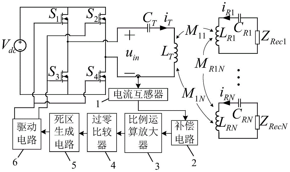
如图1所示,本发明所提供的多负载无线输电系统,包括一个自震荡发射电路和多个接收电路;所述自震荡发射电路包括一个工作在零电压开通状态下的自震荡逆变电路以及串联在一起的发射线圈LT和发射端补偿电容CT,所述自震荡逆变电路由控制回路和作为主电路的全桥逆变电路组成,所述控制回路由电流互感器1、补偿电路2、比例运算放大器3、过零比较器4、死区生成电路5和驱动电路6依次串联组成,其中,所述电流互感器1的原边与发射线圈LT、发射端补偿电容CT串联在一起,副边与补偿电路2连接,所述驱动电路6产生的驱动信号控制全桥逆变电路的开关管开通和关断,从而为系统提供交变的能量,所述全桥逆变电路由直流电压源Vdc及与该直流电压源Vdc连接的4个开关管S1、S2、S3、S4组成;所述发射线圈LT为一个能够产生平面均匀磁场的平面盘式线圈,其匝间距从外到内逐渐变大;每个接收电路均由接收线圈LRN、接收端补偿电容CRN和负载ZRecN依次串联组成,所述发射线圈LT与多个接收电路的接收线圈LRN之间通过电磁耦合的方式实现电能的无线传输。As shown in FIG. 1, the multi-load wireless power transmission system provided by the present invention includes a self-oscillating transmitting circuit and a plurality of receiving circuits; the self-oscillating transmitting circuit includes a self-oscillating inverter circuit that operates in a zero-voltage on state And the transmitting coil L T and the transmitting end compensation capacitor C T connected in series, the self-oscillating inverter circuit is composed of a control loop and a full-bridge inverter circuit as the main circuit, and the control loop is composed of a
本发明的工作原理为:利用自震荡逆变电路为无线输电系统提供能量,发射线圈LT和多个接收线圈LRN通过电磁耦合的方式实现电能的无线传输;在自震荡逆变电路中的电流互感器1和比例运算放大器3之间串联一个补偿电路2,使得驱动电路6驱动信号超前于发射线圈LT所通过电流信号,从而保证全桥逆变电路输出电压信号uin超前于输出电流信号iT,从而可实现全桥逆变电路的开关管的零电压开通,降低开关损耗,提高系统效率;全桥逆变电路工作频率随系统工作条件自动改变,近似跟踪频率分裂点,因此提高系统输出能量和传输特性;发射线圈采用匝间距从外到内逐渐变大的平面盘式线圈,产生平面均匀磁场,改善因不同接收电路的接收线圈与发射电路的发射线圈耦合强度相差较大而带来的输出功率不均的问题,提高接收电路的放置自由度,所设计的发射线圈产生均匀磁场的效果可由发射线圈与接收线圈之间互感在同一平面上的变化所展现,如图4所示,当发射线圈与接收线圈平行放置,且传输距离为5mm时,发射线圈与接收线圈之间互感沿着发射线圈中心横向轴线的变化曲线见图4中(a)所示,发射线圈与接收线圈之间互感沿着发射线圈对角轴线的变化曲线见图4中(b)所示。The working principle of the present invention is as follows: the self-oscillating inverter circuit is used to provide energy for the wireless power transmission system, and the transmitting coil L T and a plurality of receiving coils L RN realize wireless transmission of electric energy through electromagnetic coupling; A
下面我们以三负载无线输电系统为例进行具体说明。Below we take the three-load wireless power transmission system as an example for specific description.
如图2所示,所述三负载无线输电系统包括一个自震荡发射电路和三个接收电路,同样,自震荡发射电路包括一个工作在零电压开通状态下的自震荡逆变电路以及串联在一起的发射线圈LT和发射端补偿电容CT,发射线圈LT与三个接收电路的接收线圈LRN之间通过电磁耦合的方式实现电能的无线传输。该三负载无线输电系统的控制方面仅需要采样电流互感器1的原边电流,通过补偿电路2、比例运算放大器3放大信号,以及过零比较器4产生一个占空比约等于0.5的方波信号,进而通过死区生成电路5产生两个占空比小于0.5、电平信号相反且频率自动变化的方波信号,送给驱动电路6,进而驱动全桥逆变电路的开关管;自震荡逆变电路通过调节控制回路的补偿电路2使得全桥逆变电路的输出电压uin的相位稍微超前于输出电流iT的相位,即可实现全桥逆变电路的开关管零电压开通,提高系统效率。As shown in FIG. 2 , the three-load wireless power transmission system includes a self-oscillating transmitting circuit and three receiving circuits. Similarly, the self-oscillating transmitting circuit includes a self-oscillating inverter circuit that operates in a zero-voltage on state and is connected in series The transmitting coil L T and the transmitting end compensation capacitor C T , the transmission coil L T and the receiving coils L RN of the three receiving circuits realize wireless transmission of electric energy by means of electromagnetic coupling. The control of the three-load wireless power transmission system only needs to sample the primary current of the
如图3所示,本实施例提供的三负载无线输电系统,其发射线圈的匝数为7,为具有圆倒角的正方形,外径W=310mm,以导线中间部分为基准,则从外到里相邻导线之间的匝间距分别为:d1=3.5mm、d2=7.0mm、d3=14.0mm、d4=17.5mm、d5=24.5mm、d6=35.0mm。As shown in FIG. 3 , in the three-load wireless power transmission system provided in this embodiment, the number of turns of the transmitting coil is 7, which is a square with rounded corners, and the outer diameter is W=310 mm. The turn spacings between adjacent wires are: d 1 =3.5mm, d 2 =7.0mm, d 3 =14.0mm, d 4 =17.5mm, d 5 =24.5mm, d 6 =35.0mm.
本实施例提供的三负载无线输电系统,其耦合模模型可表示如下:The coupled mode model of the three-load wireless power transmission system provided in this embodiment can be expressed as follows:
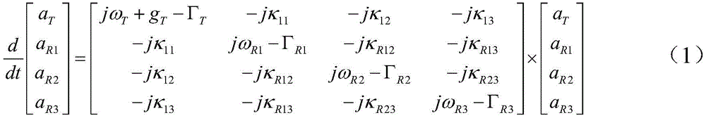
式中,aT、aR1、aR2、aR3分别表示自震荡发射电路、第一个接收电路、第二个接收电路以及第三个接收电路的能量模;gT为全桥逆变电路的增益率;ΓT、ΓR1、ΓR2、ΓR3分别为自震荡发射电路、第一个接收电路、第二个接收电路以及第三个接收电路的损耗率;ωT、ωR1、ωR2、ωR3分别为自震荡发射电路、第一个接收电路、第二个接收电路以及第三个接收电路的固有频率,且令ωT=ωR1=ωR2=ωR3=ω0;κ11、κ12、κ13分别为发射线圈与各个接收线圈的耦合率,且
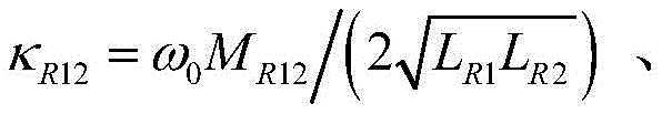

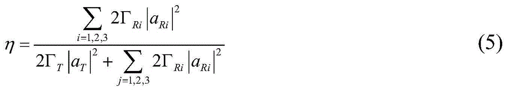
因此,第一个接收电路、第二个接收电路以及第三个接收电路所得到的功率,以及系统传输效率表示如下:Therefore, the power obtained by the first receiving circuit, the second receiving circuit and the third receiving circuit, and the system transmission efficiency are expressed as follows:
PR1=2ΓR1|aR1|2 (2)P R1 = 2Γ R1 |a R1 | 2 (2)
PR2=2ΓR2|aR2|2 (3)P R2 = 2Γ R2 |a R2 | 2 (3)
PR3=2ΓR3|aR3|2 (4)P R3 = 2Γ R3 |a R3 | 2 (4)
第一个接收电路、第二个接收电路以及第三个接收电路的输出电压分别表示如下:The output voltages of the first receiving circuit, the second receiving circuit and the third receiving circuit are respectively expressed as follows:


假设接收线圈外径/内径为114mm/64mm,平面密绕螺旋结构,则发射线圈与接收线圈之间相距5mm时,它们之间的互感随径向距离变化如图4所示,当发射线圈与接收线圈平行放置,且传输距离为5mm时,发射线圈TX与接收线圈RX之间互感M的变化曲线,互感M的单位为微亨利μH;(a)为当发射线圈TX与接收线圈RX在横向之间的距离ρ变化时,互感M的变化曲线,(b)为当发射线圈TX与接收线圈RX在对角线方向上之间的距离ρ1变化时,互感M的变化曲线;图上正负号表示接收线圈的移动方向,正号+表示正方向,负号-表示反方向;全桥逆变电路中直流电压源的电压Vdc=21V;发射线圈电感值LT=21.54μH、发射端补偿电容CT=1.19nF、发射线圈寄生内阻为rT=248.00mΩ;第一个接收电路的接收线圈电感值、寄生内阻、接收端补偿电容和等效负载分别为LR1=16.69μH、rR1=182.98mΩ、CR1=1.54nF、ZRec1=8Ω;第二个接收电路的接收线圈电感值、寄生内阻、接收端补偿电容和等效负载分别为LR2=17.03μH、rR2=182.13mΩ、CR2=1.54nF、ZRec2=8Ω;第三个接收电路的接收线圈电感值、寄生内阻、接收端补偿电容和等效负载分别为LR3=16.61μH、rR3=176.83mΩ、CR3=1.54nF、ZRec3=8Ω;此时,发射线圈与各个接收线圈平行放置且距离相同,则系统各个负载输出电压和系统传输效率随传输距离的变化曲线如图5所示,(a)、(b)、(c)分别为第一个接收电路输出电压VRec1、第二个接收电路输出电压VRec2、第三个接收电路输出电压VRec3与传输距离s之间的关系曲线,(d)为系统传输效率η与传输距离s之间的关系曲线,输出电压的单位为伏特V,传输距离s的单位为毫米mm;而当发射线圈与各个接收线圈平行放置且距离相同,均为5mm时,负载电阻值从10Ω增大到100Ω,且每个负载电阻值时刻保持相同时,相应的负载输出电压和系统传输效率的变化曲线如图6所示,(a)、(b)、(c)分别为第一个接收电路输出电压VRec1、第二个接收电路输出电压VRec2、第三个接收电路输出电压VRec3与负载电阻值Rdc之间的关系曲线,(d)为系统传输效率η与负载电阻值Rdc之间的关系曲线,输出电压的单位为伏特V,负载电阻值的单位为欧姆Ω。Assuming that the outer diameter/inner diameter of the receiving coil is 114mm/64mm, and the plane densely wound helical structure, when the distance between the transmitting coil and the receiving coil is 5mm, the mutual inductance between them varies with the radial distance as shown in Figure 4. When the receiving coils are placed in parallel and the transmission distance is 5mm, the change curve of the mutual inductance M between the transmitting coil TX and the receiving coil RX, the unit of the mutual inductance M is micro Henry μH; (a) When the transmitting coil TX and the receiving coil RX are in the horizontal direction When the distance ρ changes, the change curve of the mutual inductance M, (b) is the change curve of the mutual inductance M when the distance ρ1 between the transmitting coil TX and the receiving coil RX in the diagonal direction changes; The sign indicates the moving direction of the receiving coil, the positive sign + indicates the positive direction, and the negative sign - indicates the reverse direction; the voltage of the DC voltage source in the full-bridge inverter circuit is V dc = 21V; the inductance value of the transmitting coil L T = 21.54μH, the transmitting end The compensation capacitor C T =1.19nF, the parasitic internal resistance of the transmitting coil is r T =248.00mΩ; the inductance value of the receiving coil, the parasitic internal resistance, the compensation capacitance of the receiving end and the equivalent load of the first receiving circuit are respectively L R1 =16.69μH , r R1 = 182.98mΩ, C R1 = 1.54nF, Z Rec1 = 8Ω; the receiving coil inductance, parasitic internal resistance, receiving end compensation capacitance and equivalent load of the second receiving circuit are L R2 = 17.03μH, r R2 = 182.13mΩ, C R2 = 1.54nF, Z Rec2 = 8Ω; the inductance value of the receiving coil, parasitic internal resistance, compensation capacitance of the receiving end and equivalent load of the third receiving circuit are L R3 = 16.61μH, r R3 = 176.83mΩ, C R3 = 1.54nF, Z Rec3 = 8Ω; at this time, the transmitter coil and each receiver coil are placed in parallel and the distance is the same, then the change curve of each load output voltage of the system and the transmission efficiency of the system with the transmission distance is shown in Figure 5 , (a), (b), (c) are the difference between the output voltage V Rec1 of the first receiving circuit, the output voltage V Rec2 of the second receiving circuit, the output voltage V Rec3 of the third receiving circuit and the transmission distance s, respectively The relationship curve, (d) is the relationship curve between the system transmission efficiency η and the transmission distance s, the unit of the output voltage is volt V, and the unit of the transmission distance s is mm; when the transmitting coil is placed in parallel with each receiving coil and the distance The same, when both are 5mm, the load resistance value increases from 10Ω to 100Ω, and when each load resistance value remains the same at all times, the corresponding change curve of the load output voltage and system transmission efficiency is shown in Figure 6, (a), (b) and (c) are the relationship curves between the output voltage V Rec1 of the first receiving circuit, the output voltage V Rec2 of the second receiving circuit, the output voltage V Rec3 of the third receiving circuit and the load resistance value R dc , respectively, (d) is the difference between the system transmission efficiency η and the load resistance value R dc The unit of output voltage is volt V, and the unit of load resistance value is ohm Ω.
上述实施例为本发明较佳的实施方式,但本发明的实施方式并不受所述实施例的限制,其他的任何未背离本发明的精神实质与原理下所作的改变、修饰、替代、组合、简化,均应为等效的置换方式,都包含在本发明的保护范围之内。The above-mentioned embodiments are preferred embodiments of the present invention, but the embodiments of the present invention are not limited by the described embodiments, and any other changes, modifications, substitutions, and combinations made without departing from the spirit and principle of the present invention , simplification, all should be equivalent replacement modes, and are all included in the protection scope of the present invention.
Claims (4)
Priority Applications (1)
| Application Number | Priority Date | Filing Date | Title |
|---|---|---|---|
| CN202010353055.6A CN111464063B (en) | 2020-04-29 | 2020-04-29 | A multi-load wireless power transmission system |
Applications Claiming Priority (1)
| Application Number | Priority Date | Filing Date | Title |
|---|---|---|---|
| CN202010353055.6A CN111464063B (en) | 2020-04-29 | 2020-04-29 | A multi-load wireless power transmission system |
Publications (2)
| Publication Number | Publication Date |
|---|---|
| CN111464063A true CN111464063A (en) | 2020-07-28 |
| CN111464063B CN111464063B (en) | 2024-05-07 |
Family
ID=71680679
Family Applications (1)
| Application Number | Title | Priority Date | Filing Date |
|---|---|---|---|
| CN202010353055.6A Active CN111464063B (en) | 2020-04-29 | 2020-04-29 | A multi-load wireless power transmission system |
Country Status (1)
| Country | Link |
|---|---|
| CN (1) | CN111464063B (en) |
Cited By (6)
| Publication number | Priority date | Publication date | Assignee | Title |
|---|---|---|---|---|
| CN112234722A (en) * | 2020-12-14 | 2021-01-15 | 中国人民解放军海军工程大学 | An S-LCC type inductive power transmission system and its dynamic tuning method |
| CN112290696A (en) * | 2020-10-27 | 2021-01-29 | 济南大学 | A wireless power transmission system and method capable of suppressing frequency splitting |
| CN112564308A (en) * | 2020-11-30 | 2021-03-26 | 哈尔滨工业大学 | Double-frequency compensation and power decoupling control system for double-load WPT system |
| CN115864679A (en) * | 2023-02-09 | 2023-03-28 | 北京理工大学 | Determination method and system applicable to multi-load wireless power transmission system |
| CN118054447A (en) * | 2024-01-10 | 2024-05-17 | 华中科技大学 | A control method for a multi-unit modular bidirectional wireless power transmission system |
| WO2025091546A1 (en) * | 2023-10-31 | 2025-05-08 | 宁波道充科技有限公司 | Wireless power transfer system capable of achieving self-oscillation by energizing and blocking oscillation |
Citations (8)
| Publication number | Priority date | Publication date | Assignee | Title |
|---|---|---|---|---|
| US6072710A (en) * | 1998-12-28 | 2000-06-06 | Philips Electronics North America Corporation | Regulated self-oscillating resonant converter with current feedback |
| CN1397150A (en) * | 2000-12-05 | 2003-02-12 | 皇家菲利浦电子有限公司 | Electronic ballast with feed-forward control |
| CN106532987A (en) * | 2016-12-22 | 2017-03-22 | 东南大学 | Load identification method for multi-load wireless electric energy transmission system |
| CN108233552A (en) * | 2018-02-02 | 2018-06-29 | 华南理工大学 | A kind of hybrid wireless electric energy Transmission system based on additional self-oscillation power supply |
| CN108809114A (en) * | 2018-06-21 | 2018-11-13 | 戴金红 | Inversion electric resistance welder power supply |
| CN108832726A (en) * | 2018-05-31 | 2018-11-16 | 杭州电子科技大学 | A kind of control circuit in resonance type wireless charging system |
| CN110943551A (en) * | 2019-12-13 | 2020-03-31 | 华南理工大学 | A multi-load wireless power transmission system with constant power and constant efficiency |
| CN212012495U (en) * | 2020-04-29 | 2020-11-24 | 华南理工大学 | A multi-load wireless power transmission system |
-
2020
- 2020-04-29 CN CN202010353055.6A patent/CN111464063B/en active Active
Patent Citations (8)
| Publication number | Priority date | Publication date | Assignee | Title |
|---|---|---|---|---|
| US6072710A (en) * | 1998-12-28 | 2000-06-06 | Philips Electronics North America Corporation | Regulated self-oscillating resonant converter with current feedback |
| CN1397150A (en) * | 2000-12-05 | 2003-02-12 | 皇家菲利浦电子有限公司 | Electronic ballast with feed-forward control |
| CN106532987A (en) * | 2016-12-22 | 2017-03-22 | 东南大学 | Load identification method for multi-load wireless electric energy transmission system |
| CN108233552A (en) * | 2018-02-02 | 2018-06-29 | 华南理工大学 | A kind of hybrid wireless electric energy Transmission system based on additional self-oscillation power supply |
| CN108832726A (en) * | 2018-05-31 | 2018-11-16 | 杭州电子科技大学 | A kind of control circuit in resonance type wireless charging system |
| CN108809114A (en) * | 2018-06-21 | 2018-11-13 | 戴金红 | Inversion electric resistance welder power supply |
| CN110943551A (en) * | 2019-12-13 | 2020-03-31 | 华南理工大学 | A multi-load wireless power transmission system with constant power and constant efficiency |
| CN212012495U (en) * | 2020-04-29 | 2020-11-24 | 华南理工大学 | A multi-load wireless power transmission system |
Non-Patent Citations (1)
| Title |
|---|
| YANWEI JIANG 等: "A Fractional-Order Wireless Power Transfer System Insensitive to Resonant Frequency", IEEE, vol. 35, no. 5, 14 October 2019 (2019-10-14), pages 5496 - 5505, XP011775389, DOI: 10.1109/TPEL.2019.2946964 * |
Cited By (8)
| Publication number | Priority date | Publication date | Assignee | Title |
|---|---|---|---|---|
| CN112290696A (en) * | 2020-10-27 | 2021-01-29 | 济南大学 | A wireless power transmission system and method capable of suppressing frequency splitting |
| CN112564308A (en) * | 2020-11-30 | 2021-03-26 | 哈尔滨工业大学 | Double-frequency compensation and power decoupling control system for double-load WPT system |
| CN112564308B (en) * | 2020-11-30 | 2021-10-08 | 哈尔滨工业大学 | A dual-frequency compensation and power decoupling control system for dual-load WPT system |
| CN112234722A (en) * | 2020-12-14 | 2021-01-15 | 中国人民解放军海军工程大学 | An S-LCC type inductive power transmission system and its dynamic tuning method |
| CN115864679A (en) * | 2023-02-09 | 2023-03-28 | 北京理工大学 | Determination method and system applicable to multi-load wireless power transmission system |
| WO2025091546A1 (en) * | 2023-10-31 | 2025-05-08 | 宁波道充科技有限公司 | Wireless power transfer system capable of achieving self-oscillation by energizing and blocking oscillation |
| US12444986B1 (en) | 2023-10-31 | 2025-10-14 | Ningbo Douchpower Technology Co., Ltd. | Wireless power transfer system for zero current switching operation under charge-block oscillation |
| CN118054447A (en) * | 2024-01-10 | 2024-05-17 | 华中科技大学 | A control method for a multi-unit modular bidirectional wireless power transmission system |
Also Published As
| Publication number | Publication date |
|---|---|
| CN111464063B (en) | 2024-05-07 |
Similar Documents
| Publication | Publication Date | Title |
|---|---|---|
| CN111464063A (en) | A multi-load wireless power transmission system | |
| CN104753152B (en) | The induction type charging system of constant current constant voltage Compound Topology | |
| CN103199634B (en) | The phased capacitance tuning device of magnet coupled resonant type wireless delivery of electrical energy | |
| CN103560593B (en) | A kind of control method of field coupled type radio energy transmission system | |
| CN112003385A (en) | Single-transmitting multi-receiving wireless charging device | |
| CN104362769B (en) | A kind of wireless power transfer system | |
| CN108808875B (en) | Constant-current and constant-voltage wireless charging system and wireless charging method suitable for battery characteristics | |
| CN112259349B (en) | A self-resonant coil of a wireless power transmission system | |
| CN111799895A (en) | A magnetic coupling structure and wireless power transmission system | |
| CN105186720B (en) | A kind of transmitting coil structure and apply its radio energy transmitting terminal | |
| CN110649715A (en) | A multi-frequency many-to-one wireless power supply system based on the principle of PT symmetry | |
| CN212012495U (en) | A multi-load wireless power transmission system | |
| CN206077079U (en) | A kind of wireless electric energy transmission device of constant current output | |
| CN106300448A (en) | One utilizes capacity coupled wireless electric energy transmission device | |
| CN110022005A (en) | A kind of invariable power dynamic radio electric energy Transmission system of mobile load | |
| CN108183616B (en) | low-stress high-frequency DC/DC power converter based on transformer leakage inductance | |
| CN106487105B (en) | A kind of magnet coupled resonant type wireless power transfer of modified line coil structures | |
| CN204947740U (en) | A kind of resonance type wireless electric energy transmission system based on two E class power amplifier | |
| CN107733093A (en) | A kind of Capacitance Coupled resonance type wireless energy transmission system and method | |
| CN104868612A (en) | Resonant wireless electric energy transmission system based on E-type power amplifier | |
| CN205509853U (en) | Static magnetic resistance type magnetoelectric amplifier | |
| CN206452186U (en) | A system that improves the efficiency of wireless power transfer | |
| CN210806854U (en) | Multi-frequency many-to-one wireless power supply system based on PT (potential Transformer) symmetry principle | |
| CN108400656A (en) | WPT system based on three-dimensional dipole coil and its Parameters design | |
| CN201956756U (en) | Resonant wireless energy transmission device |
Legal Events
| Date | Code | Title | Description |
|---|---|---|---|
| PB01 | Publication | ||
| PB01 | Publication | ||
| SE01 | Entry into force of request for substantive examination | ||
| SE01 | Entry into force of request for substantive examination | ||
| GR01 | Patent grant | ||
| GR01 | Patent grant |