CN111388795A - A mobile medical device suitable for stroke patients - Google Patents
A mobile medical device suitable for stroke patients Download PDFInfo
- Publication number
- CN111388795A CN111388795A CN202010214134.9A CN202010214134A CN111388795A CN 111388795 A CN111388795 A CN 111388795A CN 202010214134 A CN202010214134 A CN 202010214134A CN 111388795 A CN111388795 A CN 111388795A
- Authority
- CN
- China
- Prior art keywords
- syringe pump
- sealing element
- medical device
- mobile medical
- pump housing
- Prior art date
- Legal status (The legal status is an assumption and is not a legal conclusion. Google has not performed a legal analysis and makes no representation as to the accuracy of the status listed.)
- Pending
Links
Images


Classifications
-
- A—HUMAN NECESSITIES
- A61—MEDICAL OR VETERINARY SCIENCE; HYGIENE
- A61M—DEVICES FOR INTRODUCING MEDIA INTO, OR ONTO, THE BODY; DEVICES FOR TRANSDUCING BODY MEDIA OR FOR TAKING MEDIA FROM THE BODY; DEVICES FOR PRODUCING OR ENDING SLEEP OR STUPOR
- A61M5/00—Devices for bringing media into the body in a subcutaneous, intra-vascular or intramuscular way; Accessories therefor, e.g. filling or cleaning devices, arm-rests
- A61M5/14—Infusion devices, e.g. infusing by gravity; Blood infusion; Accessories therefor
- A61M5/142—Pressure infusion, e.g. using pumps
-
- A—HUMAN NECESSITIES
- A61—MEDICAL OR VETERINARY SCIENCE; HYGIENE
- A61G—TRANSPORT, PERSONAL CONVEYANCES, OR ACCOMMODATION SPECIALLY ADAPTED FOR PATIENTS OR DISABLED PERSONS; OPERATING TABLES OR CHAIRS; CHAIRS FOR DENTISTRY; FUNERAL DEVICES
- A61G5/00—Chairs or personal conveyances specially adapted for patients or disabled persons, e.g. wheelchairs
- A61G5/10—Parts, details or accessories
- A61G5/12—Rests specially adapted therefor, e.g. for the head or the feet
-
- A—HUMAN NECESSITIES
- A61—MEDICAL OR VETERINARY SCIENCE; HYGIENE
- A61M—DEVICES FOR INTRODUCING MEDIA INTO, OR ONTO, THE BODY; DEVICES FOR TRANSDUCING BODY MEDIA OR FOR TAKING MEDIA FROM THE BODY; DEVICES FOR PRODUCING OR ENDING SLEEP OR STUPOR
- A61M5/00—Devices for bringing media into the body in a subcutaneous, intra-vascular or intramuscular way; Accessories therefor, e.g. filling or cleaning devices, arm-rests
- A61M5/14—Infusion devices, e.g. infusing by gravity; Blood infusion; Accessories therefor
- A61M5/1414—Hanging-up devices
- A61M5/1415—Stands, brackets or the like for supporting infusion accessories
-
- B—PERFORMING OPERATIONS; TRANSPORTING
- B64—AIRCRAFT; AVIATION; COSMONAUTICS
- B64D—EQUIPMENT FOR FITTING IN OR TO AIRCRAFT; FLIGHT SUITS; PARACHUTES; ARRANGEMENT OR MOUNTING OF POWER PLANTS OR PROPULSION TRANSMISSIONS IN AIRCRAFT
- B64D11/00—Passenger or crew accommodation; Flight-deck installations not otherwise provided for
- B64D11/06—Arrangements of seats, or adaptations or details specially adapted for aircraft seats
- B64D11/0639—Arrangements of seats, or adaptations or details specially adapted for aircraft seats with features for adjustment or converting of seats
- B64D11/0644—Adjustable arm rests
-
- F—MECHANICAL ENGINEERING; LIGHTING; HEATING; WEAPONS; BLASTING
- F16—ENGINEERING ELEMENTS AND UNITS; GENERAL MEASURES FOR PRODUCING AND MAINTAINING EFFECTIVE FUNCTIONING OF MACHINES OR INSTALLATIONS; THERMAL INSULATION IN GENERAL
- F16J—PISTONS; CYLINDERS; SEALINGS
- F16J15/00—Sealings
- F16J15/02—Sealings between relatively-stationary surfaces
- F16J15/06—Sealings between relatively-stationary surfaces with solid packing compressed between sealing surfaces
- F16J15/10—Sealings between relatively-stationary surfaces with solid packing compressed between sealing surfaces with non-metallic packing
- F16J15/102—Sealings between relatively-stationary surfaces with solid packing compressed between sealing surfaces with non-metallic packing characterised by material
-
- F—MECHANICAL ENGINEERING; LIGHTING; HEATING; WEAPONS; BLASTING
- F16—ENGINEERING ELEMENTS AND UNITS; GENERAL MEASURES FOR PRODUCING AND MAINTAINING EFFECTIVE FUNCTIONING OF MACHINES OR INSTALLATIONS; THERMAL INSULATION IN GENERAL
- F16J—PISTONS; CYLINDERS; SEALINGS
- F16J15/00—Sealings
- F16J15/02—Sealings between relatively-stationary surfaces
- F16J15/06—Sealings between relatively-stationary surfaces with solid packing compressed between sealing surfaces
- F16J15/10—Sealings between relatively-stationary surfaces with solid packing compressed between sealing surfaces with non-metallic packing
- F16J15/104—Sealings between relatively-stationary surfaces with solid packing compressed between sealing surfaces with non-metallic packing characterised by structure
Landscapes
- Health & Medical Sciences (AREA)
- Engineering & Computer Science (AREA)
- General Engineering & Computer Science (AREA)
- Animal Behavior & Ethology (AREA)
- Life Sciences & Earth Sciences (AREA)
- General Health & Medical Sciences (AREA)
- Public Health (AREA)
- Veterinary Medicine (AREA)
- Biomedical Technology (AREA)
- Heart & Thoracic Surgery (AREA)
- Hematology (AREA)
- Anesthesiology (AREA)
- Vascular Medicine (AREA)
- Mechanical Engineering (AREA)
- Aviation & Aerospace Engineering (AREA)
- Infusion, Injection, And Reservoir Apparatuses (AREA)
Abstract
本发明涉及一种适用于脑卒中患者的移动医疗装置,该移动医疗装置包括:注射泵壳体,其具有壳体开放端和用于存储药物的储药筒;泵驱动装置,其被配置于所述注射泵壳体中以用于分配所述储药筒中的药物;盖合组件,其通过与所述壳体开放端相接合而装配于所述注射泵壳体上以用于将从储药筒中分配出的药物输送至所述注射泵壳体外部,其中,装配于所述注射泵壳体上的所述盖合组件端部外壁与所述注射泵壳体内壁之间形成轴向微小间隙,所述盖合组件具有第一密封元件,所述第一密封元件位于彼此相接的所述注射泵壳体与所述盖合组件之间的接合位置处且与所述轴向微小间隙相连通。
The present invention relates to a mobile medical device suitable for stroke patients. The mobile medical device comprises: a syringe pump housing, which has an open end of the housing and a drug storage cartridge for storing medicine; a pump driving device, which is configured in in the syringe pump housing for dispensing the drug in the cartridge; a capping assembly assembled on the syringe pump housing by engaging with the open end of the housing for removing the drug from the reservoir; The medicine dispensed in the cartridge is delivered to the outside of the syringe pump housing, wherein an axial microscopic micrometer is formed between the outer wall of the end of the capping assembly assembled on the syringe pump housing and the inner wall of the syringe pump housing. a gap, the capping assembly has a first sealing element, the first sealing element is located at the joint position between the syringe pump housing and the capping assembly that are in contact with each other and is connected to the axial slight gap connected.
Description
技术领域technical field
本发明涉及以注射方式将介质引入体内的输注器械技术领域,尤其涉及一种适用于脑卒中患者的移动医疗装置。The invention relates to the technical field of infusion devices for introducing media into the body by injection, in particular to a mobile medical device suitable for stroke patients.
背景技术Background technique
脑卒中(Cerebral Stroke,又称中风或脑血管意外),是指因脑部血管突然破裂或血管阻塞导致血液循环障碍而引起的脑组织损害的一组疾病,包括缺血性卒中(IschemicStroke)和出血性卒中(Hemorrhagic Stroke)两类。脑卒中作为一类常见的神经系统疾病,因其发病率、死亡率、复发率和致残率均较高,已经成为严重威胁居民生命健康和生活质量的重大疾病。糖尿病是缺血性脑卒中的独立危险因素,长期高血糖增加中风风险,糖尿病患者中风发病率是正常人的四倍,高血糖通过多种途径损伤脑血管导致动脉粥样硬化,影响血管壁弹性和硬度,出现血管内膜斑块形成、狭窄、闭塞等病理改变,由于血脂异常、高血压、动脉粥样硬化、血液黏稠度增高等并发症导致心脏、大脑及全身组织受损,发生缺血性或出血性症状,即心脑血管并发症,主要表现之一就是缺血性脑卒中。Cerebral Stroke (Cerebral Stroke, also known as stroke or cerebrovascular accident) refers to a group of diseases that damage brain tissue caused by sudden rupture of blood vessels in the brain or obstruction of blood vessels, including ischemic stroke (Ischemic Stroke) and Hemorrhagic stroke (Hemorrhagic Stroke) two categories. As a common neurological disease, stroke has become a major disease that seriously threatens residents' life, health and quality of life because of its high morbidity, mortality, recurrence and disability rates. Diabetes is an independent risk factor for ischemic stroke. Long-term hyperglycemia increases the risk of stroke. The incidence of stroke in diabetic patients is four times that of normal people. Hyperglycemia damages cerebral blood vessels through various pathways, leading to atherosclerosis and affecting the elasticity of blood vessel walls. Due to complications such as dyslipidemia, hypertension, atherosclerosis, and increased blood viscosity, the heart, brain and systemic tissues are damaged and ischemia occurs. One of the main manifestations of sexual or hemorrhagic symptoms, namely cardiovascular and cerebrovascular complications, is ischemic stroke.
急性脑卒中(Acute Cardiovascular Disease,ACVD)是内外科急危症之一,其病因复杂、进展迅速,国内80%~90%的超早期脑梗死是血栓堵塞脑动脉所致,只有早期溶栓和再通闭塞的脑血管才能挽救缺血半暗带中的脑组织,避免缺血脑细胞的坏死。溶栓治疗有严格的时间限定,必须在规定的时间内对患者进行及时地诊断和治疗,而即便符合溶栓治疗条件的患者溶栓也不是绝对安全的。许多基础研究已证实,脑出血患者发生活动性再出血的概率与脑出血后的时间成反比,特别是在6小时以内,即脑组织缺血超过6个小时就会发生永久性神经损害,而缺血的脑组织一旦死亡,溶栓治疗将彻底失去作用,甚至可能导致溶栓性症状性脑出血。研究显示溶栓治疗导致脑出血的患者的比例约为1%~5%,而一旦溶栓治疗出现脑出血,则比普通出血止血更加困难,甚至导致死亡。因此对脑卒中患者进行及时的诊断和治疗极为重要。据报道,武汉市第三医院就曾对一名患者的抢救用快速、及时、高效跑出了脑卒中抢救的“中国速度”,使患者得到了及时有效的救治,在急救车到达后确诊缺血性脑卒中的第一时间,医护人员随即取出便携式溶栓包里的微量注射泵,将溶栓类药物注入病人体内,便捷移动医疗装置为医护人员赢得宝贵的抢救时间。Acute stroke (Acute Cardiovascular Disease, ACVD) is one of the emergency medical and surgical diseases, its etiology is complex and the progress is rapid, 80% to 90% of ultra-early cerebral infarction in China is caused by thrombus blocking the cerebral artery, only early thrombolysis and Recanalization of the occluded cerebral blood vessels can save the brain tissue in the ischemic penumbra and avoid the necrosis of ischemic brain cells. Thrombolytic therapy has a strict time limit, and patients must be diagnosed and treated in a timely manner within the specified time, and even patients who meet the conditions for thrombolytic therapy are not absolutely safe. Many basic studies have confirmed that the probability of active rebleeding in patients with cerebral hemorrhage is inversely proportional to the time after cerebral hemorrhage, especially within 6 hours, that is, permanent neurological damage will occur within 6 hours of cerebral ischemia. Once the ischemic brain tissue dies, thrombolytic therapy will be completely useless, and may even lead to thrombolytic symptomatic cerebral hemorrhage. Studies have shown that the proportion of patients with cerebral hemorrhage caused by thrombolytic therapy is about 1% to 5%, and once cerebral hemorrhage occurs with thrombolytic therapy, it is more difficult to stop bleeding than ordinary bleeding, and even leads to death. Therefore, timely diagnosis and treatment of stroke patients are extremely important. According to reports, Wuhan No. 3 Hospital once ran out of the "Chinese speed" of stroke rescue with fast, timely and efficient rescue of a patient, so that the patient was treated in a timely and effective manner. At the first moment of hemorrhagic stroke, the medical staff immediately took out the microinjection pump in the portable thrombolysis bag and injected the thrombolytic drugs into the patient's body. The convenient mobile medical device won precious rescue time for the medical staff.
作为临床输注药液的高精度医疗仪器——注射泵,由微处理器控制,具有恒定压力,完善数据显示,能按需要值精确控制输液速度和输液量;能二十四小时维持静脉输液,保证血药有效浓度,减少输液副作用及并发症;输液堵塞或输液完毕能及时报警提示护士进行处理。注射泵系统则由控制系统、输入系统、输出系统、步进电机、状态检测系统、注射器、电源、报警系统等部件组成。主控模块用单片机来实现对整个系统的控制,包括工作控制、参数计算、键盘输入状态显示、压力检测,自动标注和自动报警等功能。电源电路由电源选择、充电部分及电压提升部分组成。电源电路提供元件的工作电源,能自动切换内、外电源,使用外部电源时,自动对内部电源充电。充电完成后自动断开充电线路。如果外部断电,内部电源能自动供电。步进电机连接模块要求电动机控制系统能实现高转矩、低振动水平、低噪声、快速响应和高效驱动。步进电动机分配控制器,获得准正弦波驱动电流。时钟信号控制步进电动机的速度。在得到电路的指令后,步进电机驱动电路就得到加载电压,通过一定的脉冲激励驱动步进电机,步进电动机在一定规律的脉冲频率下做转动,然后将动力源传动到二级减速箱进行减速,使得输出的速度得到进一步细化而传到丝杆,丝杆通过与半螺母结构形成外循环滚动螺旋副从而精确地把速度传到挡板处,提供了稳定而精确的进给运动。自动报警系统主要包括:脱落示警、系统示警、正常工作指示、电池示警、外电源示警等功能。采用蜂鸣器发声或发光二极管发光产生示警信号。压力检测系统。传感器是一种能感受或响应规定的被测量物理量,并按一定规律转换成可用信号输出的器件或装置,它可将输入变量转换成可供检测的电信号,并将各种参量送入计算机系统,进行智能监测、控制,是测量系统中的一种前置部件。常用的压力传感器有电阻应变片压力传感器、半导体应变片压力传感器、压阻式压力传感器、电感式压力传感器、电容式压力传感器、谐振式压力传感器及电容式加速度传感器,光纤压力传感器等。常可用于注射泵的是电阻式压力传感器。电阻式传感器的工作原理是将被测的非电量转换成电阻值,通过测量此电阻值达到测量非电量的目的,采用电桥构成测量电压,是一种具有较高灵敏度的测量方法。无差压时,电桥两臂平等。差压信号加到陶瓷压敏电阻上,压敏电阻的阻值随差压而变化,引起电桥失衡。电桥失衡引起电流的变化,通过放大后,把模拟信号转化为数字信号,再传输至CPU进行处理。工作时,单片机系统发出控制脉冲使步进电机旋转,而步进电机带动丝杆将旋转运动变成直线运动,推动注射器的活塞进行注射输液,实现高精度,平稳无脉动的液体传输。注射速度可由操作人员通过键盘操作进行设定。注射泵启动后,CPU借助于D/A转换提供电机驱动电压。电机旋转检测电路为一组光电耦合电路,通过电机的旋转产生脉冲信号,这一脉冲信号反馈到CPU,CPU根据这一反馈控制电机电压,以便获得设定的转速。As a high-precision medical instrument for clinical infusion of liquid medicine, the syringe pump is controlled by a microprocessor, has a constant pressure, perfect data display, and can accurately control the infusion speed and infusion volume according to the required value; it can maintain intravenous infusion for 24 hours , to ensure the effective concentration of blood drugs, reduce infusion side effects and complications; infusion blockage or completion of infusion can prompt the nurse to deal with the timely alarm. Syringe pump system consists of control system, input system, output system, stepper motor, state detection system, syringe, power supply, alarm system and other components. The main control module uses a single-chip microcomputer to realize the control of the entire system, including work control, parameter calculation, keyboard input status display, pressure detection, automatic labeling and automatic alarm functions. The power circuit is composed of power selection, charging part and voltage boosting part. The power supply circuit provides the working power of the components, can automatically switch the internal and external power supply, and automatically charge the internal power supply when the external power supply is used. After charging is completed, the charging line is automatically disconnected. If the external power is cut off, the internal power supply can automatically supply power. Stepper motor connection modules require motor control systems capable of high torque, low vibration levels, low noise, fast response, and efficient drive. Stepper motor distribution controller to obtain quasi-sine wave drive current. The clock signal controls the speed of the stepper motor. After getting the command of the circuit, the stepper motor drive circuit gets the loading voltage, drives the stepper motor through a certain pulse excitation, the stepper motor rotates at a certain regular pulse frequency, and then drives the power source to the secondary reduction box Decelerate, so that the output speed is further refined and transmitted to the lead screw. The lead screw forms an external circulation rolling screw pair with the half-nut structure to accurately transmit the speed to the baffle, providing a stable and accurate feeding motion. . The automatic alarm system mainly includes: shedding warning, system warning, normal working indication, battery warning, external power warning and other functions. Use buzzer to sound or light-emitting diode to generate warning signal. Pressure detection system. A sensor is a device or device that can feel or respond to a specified physical quantity to be measured and convert it into a usable signal output according to a certain rule. It can convert the input variable into an electrical signal that can be detected, and send various parameters to the computer. It is a kind of front-end component in the measurement system for intelligent monitoring and control. Commonly used pressure sensors include resistance strain gauge pressure sensor, semiconductor strain gauge pressure sensor, piezoresistive pressure sensor, inductive pressure sensor, capacitive pressure sensor, resonant pressure sensor and capacitive acceleration sensor, optical fiber pressure sensor, etc. Often used in syringe pumps are resistive pressure sensors. The working principle of the resistive sensor is to convert the measured non-electrical quantity into a resistance value, and the purpose of measuring the non-electrical quantity is achieved by measuring the resistance value. When there is no differential pressure, the two arms of the bridge are equal. The differential pressure signal is applied to the ceramic varistor, and the resistance of the varistor changes with the differential pressure, causing the bridge to be unbalanced. The unbalance of the bridge causes the change of the current. After amplification, the analog signal is converted into a digital signal, and then transmitted to the CPU for processing. When working, the single-chip microcomputer system sends out control pulses to make the stepper motor rotate, and the stepper motor drives the screw to turn the rotary motion into a linear motion, and pushes the piston of the syringe for injection and infusion, achieving high-precision, stable and pulsation-free liquid transmission. The injection speed can be set by the operator through keyboard operation. After the syringe pump is started, the CPU provides the motor drive voltage by means of D/A conversion. The motor rotation detection circuit is a group of photoelectric coupling circuits, which generate a pulse signal through the rotation of the motor, and this pulse signal is fed back to the CPU, and the CPU controls the motor voltage according to this feedback to obtain the set speed.
注射泵因其优异的精准定量特性已经在输血、麻醉注射、抗癌剂摄入、止痛药注射等领域得到了广泛地应用,国内外也有不少发明专利成果。例如,现有技术中如授权公告日为2016年06月08日的公告号为CN205286820U的专利文献所公开的航空移动重症监护抢救设备,主要包括护栏板、电源箱、支撑腿、设备仓,设备仓端面一侧内部安装有心脏除颤器,另一侧安装有注射泵,设备仓中间内部装配有呼吸机,呼吸机边侧设置有输液泵,输液泵边侧安装有调节钮。其有益效果在于:整个装置结构紧凑、轻便、可搬运;内置重症监护设备;轻质复合结构民用、军用均可,配备氧气设备或外接救护车、飞机的氧气供应。Syringe pumps have been widely used in the fields of blood transfusion, anesthesia injection, intake of anticancer agents, and painkiller injection due to their excellent and precise quantitative characteristics. There are also many invention patents at home and abroad. For example, in the prior art, the aviation mobile intensive care rescue equipment disclosed in the patent document with the announcement number CN205286820U whose authorization announcement date is June 8, 2016 mainly includes guardrails, power boxes, support legs, equipment compartments, and equipment. A cardiac defibrillator is installed on one side of the end face of the warehouse, a syringe pump is installed on the other side, a ventilator is installed in the middle of the equipment warehouse, an infusion pump is installed on the side of the ventilator, and an adjustment button is installed on the side of the infusion pump. The beneficial effects are as follows: the whole device has a compact, light and portable structure; built-in intensive care equipment; the light composite structure can be used for both civil and military use, and is equipped with oxygen equipment or external oxygen supply for ambulances and airplanes.
又如授权公告日为2018年12月21日的公告号为CN208259980U的专利文献所公开的一种注射泵,注射泵包括:注射泵本体、传动机构、监测机构;其中,传动机构包括:滑块、滑轨和推杆、推柄,滑块能够沿滑轨往复移动;监测机构包括:监测滑块移动位置的传感器,设置于滑块上并能够与滑块同步移动;该注射泵还包括:设置于注射泵本体内的用于接收传感器监测的滑块移动位置的数据、并根据滑块移动位置数据计算滑块当前位置和/或注射器内剩余药液和/或注射剩余时间向报警机构发送报警指令的控制机构;设置于注射泵本体内的用于根据接收的报警指令发出报警信号的报警机构。利用该注射泵,可使药液注射状态的监测过程稳定可靠,并且检测过程不受注射器的结构构造等限制因素的影响。Another example is a syringe pump disclosed in the patent document with the announcement number CN208259980U on December 21, 2018. The syringe pump includes: a syringe pump body, a transmission mechanism, and a monitoring mechanism; wherein, the transmission mechanism includes: a slider , slide rail, push rod, push handle, the slide block can reciprocate along the slide rail; the monitoring mechanism includes: a sensor for monitoring the moving position of the slide block, which is arranged on the slide block and can move synchronously with the slide block; the syringe pump also includes: Set in the syringe pump body to receive the data of the moving position of the slider monitored by the sensor, and calculate the current position of the slider and/or the remaining liquid medicine in the syringe and/or the remaining time of injection according to the data of the moving position of the slider, and send it to the alarm mechanism The control mechanism of the alarm instruction; the alarm mechanism arranged in the syringe pump body and used to send out an alarm signal according to the received alarm instruction. By using the syringe pump, the monitoring process of the injection state of the medicinal liquid can be stable and reliable, and the detection process is not affected by restrictive factors such as the structure of the syringe.
又如公开日为2019年06月18日的公开号为CN109893719A的专利文献所公开的一种注射泵,包括外壳主体,设置于外壳主体内、用于固定注射器的固定机构,可滑动地设置于外壳主体上、用于按压注射器的推动机构,设置于外壳主体内、与推动机构传动连接的驱动机构;所述注射泵还包括控制电路、显示面板、键盘输入面板和检测模块;所述控制电路设置于外壳主体内,用于控制和协调注射泵各个机构的工作;所述显示面板设置于外壳主体上,用于显示注射泵工作情况;所述键盘输入面板设置于外壳主体上,用于设定注射泵的工作条件,比如选择注射泵的注射时间、注射速度等;所述检测模块设置于固定机构上,用于分别检测注射器的流量变化和重量变化;所述显示面板、键盘输入面板和检测模块分别连接于控制电路。所述检测模块包括若干红外对管和压力传感器,用于实时检测注射泵的注射速度。该装置通过设置红外对管组以及压力传感器,可实时监控注射泵注射速度,减少由于注射泵注射速度异常而导致的安全事故。Another example is a syringe pump disclosed in the patent document with the publication date of June 18, 2019 and the publication number CN109893719A, comprising a housing body, a fixing mechanism arranged in the housing body and used for fixing the syringe, slidably arranged on the The push mechanism on the shell body for pressing the syringe is a drive mechanism arranged in the shell body and connected with the push mechanism; the syringe pump also includes a control circuit, a display panel, a keyboard input panel and a detection module; the control circuit It is arranged in the main body of the casing to control and coordinate the work of various mechanisms of the syringe pump; the display panel is arranged on the main body of the casing to display the working conditions of the syringe pump; the keyboard input panel is arranged on the main body of the casing to set the operation of the syringe pump. to determine the working conditions of the syringe pump, such as selecting the injection time and injection speed of the syringe pump; the detection module is arranged on the fixed mechanism and is used to detect the flow change and weight change of the syringe respectively; the display panel, the keyboard input panel and the The detection modules are respectively connected to the control circuit. The detection module includes several infrared pairs of tubes and pressure sensors for real-time detection of the injection speed of the syringe pump. The device can monitor the injection speed of the syringe pump in real time by setting the infrared pair tube group and the pressure sensor, and reduce the safety accidents caused by the abnormal injection speed of the syringe pump.
如授权公告日为2019年10月22日的公告号为CN209519190U的专利文献所提出的一种注射泵挂架,包括挂架快接底板和双层放置架,所述双层放置架通过注射泵挂架挂块固定连接在挂架快接底板上,挂架快接底板相对于双层放置架的另一侧设有若干导轨潜入零件,双层放置架内设有两个相对独立的注射泵放置区域,注射泵固定放置在双层放置架中,所述双层放置架中设有弹性固定装置,双层放置架连接的挂架快接底板通过导轨潜入零件安装在机舱内的导轨上,使注射泵稳定的放置在机舱内特定位置处,且在救援使用时,便于移动和拆卸,通过注射泵挂架对注射泵进行稳定的放置和固定,快捷方便的在直升机机舱内完成悬挂和拆卸,便于注射泵在直升机空中救援的工作。上述专利文献指出了注射泵于空中救援领域中的应用需求,解决了在空中救援的开展过程中,直接影响注射泵的使用及救援效率的注射泵在直升机机舱内的放置和固定的问题。For example, a syringe pump hanger proposed in the patent document with the announcement number CN209519190U whose authorization announcement date is October 22, 2019 includes a hanger quick-connection bottom plate and a double-layer placement rack, and the double-layer placement rack passes through the syringe pump. The hanging block of the hanger is fixedly connected to the bottom plate of the hanger quick-connection. The other side of the bottom plate of the hanger quick-connection relative to the double-layer placement rack is provided with a number of guide rail submerged parts, and two relatively independent syringe pumps are arranged in the double-layer placement rack. In the placement area, the syringe pump is fixedly placed in the double-layer placement rack, and the double-layer placement rack is provided with an elastic fixing device, and the hanger quick-connection bottom plate connected with the double-layer placement rack is installed on the guide rail in the engine room through the guide rail submerged parts, The syringe pump can be stably placed at a specific position in the cabin, and it is easy to move and disassemble during rescue use. The syringe pump is stably placed and fixed through the syringe pump hanger, and the suspension and disassembly can be completed quickly and easily in the helicopter cabin. , to facilitate the work of the syringe pump in the helicopter air rescue. The above patent documents point out the application requirements of the syringe pump in the field of air rescue, and solve the problem of placement and fixation of the syringe pump in the helicopter cabin, which directly affects the use of the syringe pump and the rescue efficiency during the development of the air rescue.
但将现有的注射泵应用于空中救援领域的情况下,不可避免地面临航行飞行过程中机舱内气压的变化,在航空环境中,压力变化对人体和输注的液体都会产生影响,注射泵内外压力不一致,可能使储液瓶内存留的气体膨胀,最终导致药液从输液管意外溢出。同时,静脉输液只有当液体的压力大于静脉压时,药物液体才有可能流入到血管内,而在药液从输液管意外溢出的情况,注射泵无法实现对输液速度和输液量的精确控制。此外,空中气流颠簸会造成储液瓶、输液管内药液和空气混合,造成空气随输液管进入人体循环系统的几率大大增加,此时对患者用药反而使得空气栓塞的发生几率大大增加。However, when the existing syringe pump is applied to the field of air rescue, it is inevitable to face the change of the air pressure in the cabin during the flight. In the aviation environment, the pressure change will have an impact on the human body and the infused liquid. The syringe pump Inconsistent internal and external pressures may expand the gas remaining in the liquid storage bottle, eventually causing the liquid to accidentally spill from the infusion tube. At the same time, in intravenous infusion, only when the pressure of the liquid is greater than the venous pressure, the drug liquid may flow into the blood vessel, and in the case of accidental overflow of the drug liquid from the infusion tube, the syringe pump cannot achieve precise control of the infusion speed and infusion volume. In addition, the turbulent air flow will cause the liquid in the liquid storage bottle and the infusion tube to mix with the air, which will greatly increase the probability of the air entering the human circulatory system with the infusion tube.
此外,一方面由于对本领域技术人员的理解存在差异;另一方面由于发明人做出本发明时研究了大量文献和专利,但篇幅所限并未详细罗列所有的细节与内容,然而这绝非本发明不具备这些现有技术的特征,相反本发明已经具备现有技术的所有特征,而且申请人保留在背景技术中增加相关现有技术之权利。In addition, on the one hand, there are differences in the understanding of those skilled in the art; on the other hand, because the inventor has studied a large number of documents and patents when making the present invention, but the space limit does not list all the details and contents in detail, but this is by no means The present invention does not possess the features of the prior art, on the contrary, the present invention already possesses all the features of the prior art, and the applicant reserves the right to add relevant prior art to the background art.
发明内容SUMMARY OF THE INVENTION
注射泵主要由储药筒、泵驱动装置以及管路等组成相对密闭的通路,使用注射泵时,需将该通路中的储药筒内部与外部环境相连通,以实现药液的输注,但若是在外部环境气压发生快速大幅度变化的环境下使用注射泵,例如在航空飞行、潜艇下潜等环境中,储药筒中存留的气体可能导致药液的意外溢出,该情况一方面是由于:药液原本是在大气压力下被转移至储药筒中,储液筒中不可避免地存留部分气体,储液筒筒壁不完全光滑而附着有大量微小气泡,本身这些气体气泡对药液的输注是没有直接影响的,但当注射泵外部环境气压相对大气压力发生快速大幅度变化时,药液出现过饱和现象,开始逐渐分离出气体,注射泵本身相对密闭的通路无法释放出筒内气体,并使得气体压强增大,筒体内压强增大的气体使得筒体内向外输注的药液的输注速率增加;另一方面,该情况会导致注射泵不能以预期的输注速率或输注量进行输注药液,注射泵无法实现对输液速度和输液量的精确控制。此外,例如在航空飞行、潜艇下潜等容易出现气流颠簸的环境下,易造成储液筒、输液管内药液与空气相混合,空气随输液管进入人体循环系统的几率大大增加,此时对患者用药反而使得空气栓塞的发生几率增大。The syringe pump is mainly composed of a drug storage cartridge, a pump drive device and a pipeline, etc. to form a relatively closed passage. When using a syringe pump, it is necessary to connect the inside of the drug storage cartridge in the passage with the external environment to realize the infusion of the medicinal liquid. However, if the syringe pump is used in an environment with rapid and large changes in the external ambient air pressure, such as in aviation flight, submarine diving, etc., the gas remaining in the storage cartridge may cause accidental spillage of the liquid medicine. On the one hand, this situation is due to : The liquid medicine was originally transferred to the storage cartridge under atmospheric pressure, and some gas was inevitably retained in the liquid storage cylinder. The wall of the liquid storage cylinder was not completely smooth and a large number of tiny air bubbles were attached. Note that there is no direct impact, but when the external ambient pressure of the syringe pump changes rapidly and substantially relative to the atmospheric pressure, the liquid medicine appears supersaturated and begins to gradually separate the gas, and the relatively closed passage of the syringe pump itself cannot release the gas in the cylinder , and make the gas pressure increase, and the gas with the increased pressure in the barrel increases the infusion rate of the liquid medicine infused outward in the barrel; on the other hand, this situation will cause the syringe pump to fail to deliver the expected infusion rate or The injection volume is used to infuse the liquid medicine, and the syringe pump cannot achieve precise control of the infusion speed and infusion volume. In addition, for example, in the environment where the air flow is prone to turbulence, such as aviation flight and submarine diving, it is easy to cause the liquid in the liquid storage tank and the infusion tube to mix with the air, and the probability of the air entering the human circulatory system with the infusion tube is greatly increased. The patient's medication actually increases the risk of air embolism.
针对现有技术之不足,本申请所提出的移动医疗装置,尤其是指可以在外部环境气压发生快速大幅度变化的环境下使用的一次性移动医疗装置,需要使用时,可以快速组装后直接连接输液设备对患者进行给药。适用于外部环境气压发生快速大幅度变化的环境下进行给药的功能的实现一方面在于,该移动医疗装置中将注射泵壳体与盖合组件之间所设置的周向微小间隙,与位于彼此相接的所述注射泵壳体与所述盖合组件之间的接合位置处的第一密封元件相连通,取消了原现有技术中本身相对密闭而无法释放出筒内气体的注射泵结构;另一方面在于,该移动医疗装置中第二密封元件与所述第一密封元件之间非一体式结构,制造工艺简单,并且在所述注射泵壳体与所述盖合组件相接合时,第二密封元件受到轴向压缩力,而使得其与第一部分内侧端面所对应的端部与所述第一密封元件之间呈非紧密贴合。不同于现有技术中通过中央处理器控制注射泵注射而无法控制因环境压力变化导致注射泵无法实现对输液速度和输液量的精确控制的技术方案,本发明所提供的移动医疗装置通过简单组装,即可实现适用于在外部环境气压发生快速大幅度变化的环境下的准确给药,并且该装置制造工艺简单,进一步降低了一次性移动医疗装置的制造成本。In view of the deficiencies of the prior art, the mobile medical device proposed in this application, especially the disposable mobile medical device that can be used in an environment where the external ambient air pressure changes rapidly and greatly, can be quickly assembled and directly connected when needed. The infusion device administers the drug to the patient. On the one hand, the realization of the function suitable for drug delivery in an environment where the external ambient air pressure changes rapidly and greatly is that, in the mobile medical device, the small circumferential gap set between the syringe pump housing and the cover assembly is connected to the The first sealing element at the joint position between the housing of the syringe pump connected to each other and the capping assembly is communicated with the first sealing element, which eliminates the syringe pump in the prior art that is relatively airtight and cannot release the gas in the cylinder structure; on the other hand, the mobile medical device has a non-integrated structure between the second sealing element and the first sealing element, the manufacturing process is simple, and the syringe pump housing is engaged with the capping assembly When the second sealing element is subjected to an axial compression force, the end portion corresponding to the inner end surface of the first part and the first sealing element are in non-tight fit. Different from the technical solution in the prior art that the injection of the syringe pump is controlled by the central processing unit, and the syringe pump cannot be controlled accurately due to the change of the environmental pressure, the mobile medical device provided by the present invention is simply assembled. , it can achieve accurate drug delivery in an environment where the external ambient air pressure changes rapidly and greatly, and the device has a simple manufacturing process, which further reduces the manufacturing cost of the disposable mobile medical device.
首先,针对本申请中轴向微小间隙进行说明:轴向指的是该间隙的流通方向主要是沿着注射泵壳体的轴向来与外部环境相连通。微小指的是用于构成该间隙的两侧端面之间的垂直宽度足够窄且是足够气体通过该垂直宽度排出的尺寸,例如可以将该两侧端面之间的垂直宽度(范围)中可以取到的最大值设定为[30μm,60μm],和/或可以取到的最小值设定为[5μm,20μm]。如图2与图3所示,间隙的形成主要是在盖合组件与壳体开放端之间相接合时所形成的。盖合组件的端部外壁的形状与壳体开放端内壁的形状相吻合。在盖合组件套接至壳体开放端的内壁中、且盖合组件与壳体开放端相对固定后,盖合组件上沿其筒状端部的周向连续延伸的外周面与所述壳体开放端上沿其筒状端部的周向连续延伸的内周面之间共同形成该轴向微小间隙。该轴向微小间隙即为在以注射泵壳体的中心轴线为旋转轴的周向上以及在注射泵壳体的轴向上均由盖合组件上沿其筒状端部的周向连续延伸的外周面与所述壳体开放端上沿其筒状端部的周向连续延伸的内周面所限定的、且在注射泵壳体的轴向上前后分别连通于壳体开放端内腔和盖合组件的外周面与至少一个垫片所限定得到的内腔相连通的空间。First, an explanation is given for the small axial gap in this application: the axial direction means that the flow direction of the gap is mainly along the axial direction of the syringe pump housing to communicate with the external environment. Small means that the vertical width between the end faces on both sides used to form the gap is narrow enough to allow gas to be discharged through the vertical width. For example, the vertical width (range) between the end faces on the two sides can be taken as The maximum attainable value is set to [30 μm, 60 μm], and/or the minimum attainable value is set to [5 μm, 20 μm]. As shown in Figures 2 and 3, the formation of the gap is mainly formed during the engagement between the cover assembly and the open end of the housing. The shape of the outer wall of the end of the closure assembly matches the shape of the inner wall of the open end of the casing. After the cover assembly is sleeved into the inner wall of the open end of the casing, and the cover assembly and the open end of the casing are relatively fixed, the outer peripheral surface of the cover assembly extending continuously along the circumferential direction of its cylindrical end is connected to the casing. The small axial gap is formed between the inner peripheral surfaces of the open end which extend continuously along the circumferential direction of the cylindrical end portion thereof. The small axial gap is a continuous extension from the cover assembly along the circumference of its cylindrical end in the circumferential direction with the central axis of the syringe pump casing as the rotation axis and in the axial direction of the syringe pump casing. The outer peripheral surface is defined by the inner peripheral surface on the open end of the casing that extends continuously along the circumference of the cylindrical end portion thereof, and is communicated with the inner cavity and the inner cavity of the open end of the casing respectively in the axial direction of the syringe pump casing. The outer peripheral surface of the capping assembly communicates with the space defined by the at least one gasket in the inner cavity.
根据本发明,适用于脑卒中患者的移动医疗装置,该移动医疗装置包括:注射泵壳体,其具有壳体开放端和用于存储药物的储药筒;泵驱动装置,其被配置于所述注射泵壳体中以用于分配所述储药筒中的药物;盖合组件,其通过与所述壳体开放端相接合而装配于所述注射泵壳体上以用于将从储药筒中分配出的药物输送至所述注射泵壳体外部,其中,装配于所述注射泵壳体上的所述盖合组件端部外壁与所述注射泵壳体内壁之间形成轴向微小间隙,所述盖合组件具有第一密封元件,所述第一密封元件位于彼此相接的所述注射泵壳体与所述盖合组件之间的接合位置处且与所述轴向微小间隙相连通。在此,本发明所提及的轴向指的是储药筒的纵向延伸方向,或指盖合组件与所述注射泵壳体相接合而并列设置的方向。以下所提及的径向即与上述轴向相垂直的方向。According to the present invention, a mobile medical device suitable for stroke patients, the mobile medical device comprises: a syringe pump housing having an open end of the housing and a drug storage cartridge for storing medicine; a pump driving device configured in all in the syringe pump housing for dispensing the medicine in the storage cartridge; a capping assembly assembled on the syringe pump housing by engaging with the open end of the housing for removing the medicine from the storage cartridge The medicine dispensed from the cartridge is delivered to the outside of the syringe pump housing, wherein a small axial gap is formed between the outer wall of the end of the capping assembly assembled on the syringe pump housing and the inner wall of the syringe pump housing , the capping assembly has a first sealing element, the first sealing element is located at the joint position between the syringe pump housing and the capping assembly that are in contact with each other and is connected with the small axial gap Pass. Here, the axial direction mentioned in the present invention refers to the longitudinal extension direction of the drug storage cartridge, or refers to the direction in which the capping assembly and the syringe pump casing are engaged and arranged side by side. The radial direction mentioned below is the direction perpendicular to the above-mentioned axial direction.
根据本发明的一种优选实施方式,所述第一密封元件在径向上具有用于提供所述注射泵壳体内部气体流动的通气路径的内侧端面。在此,内侧端面指的是呈环形的第一密封元件的内圈内壁。优选地,该第一密封元件可以是固接在注射泵壳体上,该情况下由于第一密封元件的位置固定,因此第一密封元件的尺寸精度要求较低。而第一密封元件也可以是非固接式安装至注射泵壳体上,该情况下由于第一密封元件可活动,因此第一密封元件的尺寸精度要求较高。According to a preferred embodiment of the present invention, the first sealing element has an inner end face in the radial direction for providing a ventilation path for gas flow inside the syringe pump housing. The inner end face here refers to the inner wall of the inner ring of the annular first sealing element. Preferably, the first sealing element may be fixed on the syringe pump housing. In this case, since the position of the first sealing element is fixed, the dimensional accuracy of the first sealing element is required to be low. The first sealing element may also be non-fixedly mounted on the syringe pump housing. In this case, since the first sealing element is movable, the dimensional accuracy of the first sealing element is required to be high.
根据本发明的一种优选实施方式,所述第一密封元件的内侧端面环绕于开设于所述盖合组件的端部外壁上的环状凹槽上。在此,开设有环状凹槽的所述盖合组件的端部即为与注射泵壳体的壳体开放端相接合的端部。由于内侧端面位于环状凹槽内,即第一密封元件定位在盖合组件的端部外壁上设置该环状凹槽的位置处。此处,将环状凹槽上与盖合组件外壁相平行的端面视为底面,而环状凹槽上相互平行的两环状端面视为两侧端面。对环状凹槽进一步优选地,在轴向长度上观察,其两侧端面中更靠近壳体开放端的一侧端面的轴向长度比另一侧端面的轴向长度短了一端可预设的尺寸。而相对远离壳体开放端的一侧端面的轴向长度可以是不小于所述第一密封元件的外圈直径的尺寸,该侧端面为第一密封元件提供稳定支撑,限制其变形。According to a preferred embodiment of the present invention, the inner end surface of the first sealing element surrounds an annular groove formed on the outer wall of the end portion of the cover assembly. Here, the end of the cover assembly with the annular groove is the end that is engaged with the open end of the housing of the syringe pump. Since the inner end face is located in the annular groove, that is, the first sealing element is positioned at the position where the annular groove is provided on the outer wall of the end portion of the capping assembly. Here, the end faces of the annular groove that are parallel to the outer wall of the cover assembly are regarded as the bottom face, and the two annular end faces of the annular groove that are parallel to each other are regarded as the two side end faces. It is further preferred for the annular groove, viewed in the axial length, the axial length of the end face on one side of the end faces on both sides that is closer to the open end of the casing is shorter than the axial length of the end face on the other side by a preset amount. size. The axial length of the side end surface relatively far away from the open end of the housing may be not less than the diameter of the outer ring of the first sealing element, and the side end surface provides stable support for the first sealing element to limit its deformation.
根据本发明的一种优选实施方式,所述第一密封元件至少包括具有高比表面的微孔结构材料。此处所提及的具有高比表面的微孔结构材料尤其指的是疏水透气材料。在此优选地例如该第一密封元件为膨体聚四氟乙烯(Expa nded Polytetrafluoroethylene,EPTFE),其成分是膨体聚四氟乙烯,具有极其稳定的化学性能,膜表面每平方寸有90多亿个微孔,微孔直径0.2~1.0uμm,远比水珠小10000倍以上,即使是最小的水珠(雾粒直径在25μm左右)也不能通过薄膜。优选地,储药筒上位于壳体开放端处的一端为用于输出药液的端部,在未将盖合组件与壳体开放端之间相结合之前,储药筒的该端部处以密封的方式固接有隔离膜。优选地,该隔离膜可以为具有高比表面的微孔结构材料,在此优选地例如为兼具透气性与防水性的膨体聚四氟乙烯(Expanded Polytetrafluoroethylene,EPTFE)材质。隔离膜用于在将盖合组件与壳体开放端之间相接合之前将药液与外部环境之间相隔离,同时由于隔离膜的透气性,使得该隔离膜内部即筒体内部气压与该隔离部外部即壳体开放端的内腔气压相一致。进而在盖合组件与壳体开放端之间相接合时,该隔离膜内部即筒体内部气压、该隔离部外部即壳体开放端的内腔气压均分别与所形成的轴向微小间隙相一致。一方面,针对本申请中气体的流通路径:该隔离膜内部即筒体内部气体能够通过该隔离膜进入该隔离部外部即壳体开放端的内腔,而进入壳体开放端的内腔的气体经由该轴向微小间隙进入由盖合组件的外周面与至少一个垫片所限定得到的内腔。由于第二密封元件不会对轴向微小间隙所流通至接合位置处的气体形成完全阻隔,轴向微小间隙所流通至接合位置处的气体能够经过第二密封元件的内圈部分而从第一密封元件向外部环境流通,以此提供了所述注射泵壳体内部气体流动的通气路径。另一方面,针对本申请中药液的流通路径:在盖合组件与壳体开放端之间相接合时,以设于盖合组件端部上的针尖部刺穿该隔离膜的方式,将药液从筒体内部经由该针尖部进入设于盖合组件中的流体通路,并进而沿与接合在该盖合组件中流体通路的另一端的输液设备向患者进行输注药液。According to a preferred embodiment of the present invention, the first sealing element at least comprises a microporous structure material with a high specific surface area. The microporous structure material with high specific surface mentioned here especially refers to the hydrophobic gas-permeable material. Here, for example, the first sealing element is preferably expanded polytetrafluoroethylene (Expanded Polytetrafluoroethylene, EPTFE). There are hundreds of millions of micropores, and the diameter of the micropores is 0.2 to 1.0 μm, which is more than 10,000 times smaller than that of water droplets. Even the smallest water droplets (the diameter of fog particles are about 25 μm) cannot pass through the film. Preferably, one end of the drug storage cartridge located at the open end of the housing is an end for outputting the liquid medicine, and before the capping assembly is combined with the open end of the housing, the end of the drug storage cartridge is The sealing method is fixed with an isolation film. Preferably, the isolating membrane may be a microporous structure material with a high specific surface area, preferably, for example, an expanded polytetrafluoroethylene (Expanded Polytetrafluoroethylene, EPTFE) material having both air permeability and water resistance. The isolation membrane is used to isolate the medicinal liquid from the external environment before the capping assembly and the open end of the casing are joined. The air pressure of the cavity outside the isolation portion, that is, the open end of the casing, is the same. Furthermore, when the cover assembly and the open end of the casing are engaged, the air pressure inside the isolation membrane, that is, the internal pressure of the cylinder, and the air pressure outside the isolation portion, that is, the inner cavity pressure of the open end of the casing, are respectively consistent with the formed axial micro-gap. . On the one hand, regarding the gas circulation path in the present application: the gas inside the isolation membrane, that is, the gas inside the cylinder, can enter the outside of the isolation portion, that is, the inner cavity of the open end of the casing through the isolation membrane, and the gas entering the inner cavity of the open end of the casing passes through The small axial gap enters into the inner cavity defined by the outer peripheral surface of the cover assembly and at least one gasket. Since the second sealing element does not completely block the gas flowing from the axially small gap to the joint position, the gas flowing from the axial small gap to the joint position can pass through the inner ring part of the second sealing element to escape from the first The sealing element communicates to the external environment, thereby providing a vent path for gas flow inside the syringe pump housing. On the other hand, regarding the circulation path of the medicinal liquid in the present application: when the capping assembly and the open end of the casing are engaged, the needle tip provided on the end of the capping assembly pierces the isolation membrane, and The medicinal liquid enters the fluid passage provided in the capping assembly from the inside of the barrel through the needle tip, and further infuses medicinal liquid to the patient along the infusion device engaged with the other end of the fluid passage in the capping assembly.
根据本发明的一种优选实施方式,所述盖合组件上还包括第二密封元件,所述第二密封元件与所述第一密封元件并列设置于所述接合位置处,所述第二密封元件相比于所述第一密封元件是弹性构成的。第二密封元件被构造为其最厚处的厚度比第一密封元件大。第二密封元件的径向横截面的形状大致为L形。第二密封元件与第一密封元件均类似于法兰垫片的形状,分别套接在所述环形凹槽处。优选地,第二密封元件的径向直径与第一密封元件的径向直径大致相同。所述第二密封元件与第一密封元件的材质可以均为具有高比表面的微孔结构材料。优选地,第二密封元件可以是丁腈橡胶、聚合物、塑料等具有弹性的材质。第二密封元件的安装方式可以是套接在环形凹槽上且其与第一密封元件的一端面相固接或相抵接。其中,所指的第二密封元件上与第一密封元件相固接的端面只是外圈部分与第一密封元件相固接,而内圈部分与第一密封元件间为抵接关系。According to a preferred embodiment of the present invention, the cover assembly further includes a second sealing element, the second sealing element and the first sealing element are arranged in parallel at the joint position, the second sealing element The element is of elastic design compared to the first sealing element. The second sealing element is configured to have a thickness greater than that of the first sealing element at its thickest point. The shape of the radial cross-section of the second sealing element is substantially L-shaped. Both the second sealing element and the first sealing element are similar in shape to the flange gasket, and are respectively sleeved at the annular groove. Preferably, the radial diameter of the second sealing element is substantially the same as the radial diameter of the first sealing element. The materials of the second sealing element and the first sealing element may both be microporous structure materials with high specific surface area. Preferably, the second sealing element can be made of nitrile rubber, polymer, plastic and other elastic materials. The second sealing element can be installed by being sleeved on the annular groove and fixedly connected or abutted with one end face of the first sealing element. Wherein, the end face of the second sealing element fixedly connected with the first sealing element is only the outer ring part is fixedly connected with the first sealing element, and the inner ring part is in abutting relationship with the first sealing element.
根据本发明的一种优选实施方式,所述第二密封元件在径向上的第一部分内侧端面相对第二部分内侧端面在径向上更靠近所述第二密封元件的轴心线。第一部分内侧端面相对第二部分内侧端面向内延伸的长度更长而置于环形凹槽内。相对尺寸较短的第二部分内侧端面置于环形凹槽外部。所述第二密封元件的厚度与第一密封元件的厚度共同形成注射泵壳体与盖合组件的轴向微小间隙。在此进一步优选地,该轴向微小间隙也可包括为具有用于提供所述注射泵壳体内部气体流动的通气路径。According to a preferred embodiment of the present invention, the inner end surface of the first part of the second sealing element in the radial direction is closer to the axis line of the second sealing element in the radial direction than the inner end surface of the second part. The inner end surface of the first portion extends inwardly longer than the inner end surface of the second portion and is placed in the annular groove. The inner end face of the second portion of relatively short size is placed outside the annular groove. The thickness of the second sealing element and the thickness of the first sealing element together form a small axial gap between the syringe pump housing and the cover assembly. Herein, further preferably, the axially small gap may also include a ventilation path for providing gas flow inside the syringe pump housing.
根据本发明的一种优选实施方式,所述第二密封元件在所述注射泵壳体与所述盖合组件相接合时受到轴向压缩力而使得其与第一部分内侧端面所对应的端部与所述第一密封元件之间呈非紧密贴合。该轴向压缩力是指由于在将盖合组件接合至注射泵壳体上时,注射泵壳体端部与盖合组件端部之间相对靠近,而对位于接合位置处的第二密封元件和/或第一密封元件所施加的具有压缩趋势的作用力。在本发明中,在此轴向压缩力的作用下,所述第二密封元件上与第一部分内侧端面所对应的端部与所述第一密封元件之间呈非紧密贴合。对两者施加具有压缩趋势的作用力却使得两者非紧密贴合,这里所指的非紧密贴合包括相互接触但相互作用力非常弱的情况,也包括彼此完全不存在接触点的情况。该功能的实现在于本申请中第二密封元件上的内圈部分与第一密封元件间为抵接关系,而密封垫圈的外圈部分与第一密封元件间可以是固接关系或是抵接关系。第二密封元件不会对轴向微小间隙所流通至接合位置处的气体形成完全阻隔,轴向微小间隙所流通至接合位置处的气体能够经过第二密封元件的内圈部分而从第一密封元件向外流通。在该功能下,达到了垫片对注射泵壳体与盖合组件之间的紧固密封作用,并同时提供了所述注射泵壳体内部气体流动的通气路径。According to a preferred embodiment of the present invention, the second sealing element is subjected to an axial compressive force when the syringe pump housing is engaged with the capping assembly, so that its end corresponding to the inner end face of the first part is There is a non-tight fit with the first sealing element. The axial compressive force means that when the capping assembly is joined to the syringe pump casing, the end of the syringe pump casing and the end of the capping assembly are relatively close to each other, and the second sealing element located at the joint position is relatively close to each other. and/or a force exerted by the first sealing element with a tendency to compress. In the present invention, under the action of the axial compression force, the end of the second sealing element corresponding to the inner end face of the first part is in non-tight contact with the first sealing element. Applying a force with a compressive tendency to the two causes the two to be in non-close contact. The non-close contact referred to here includes the situation where they are in contact with each other but the interaction force is very weak, and also includes the situation where there is no contact point with each other at all. The realization of this function is that in the present application, the inner ring part on the second sealing element is in abutting relationship with the first sealing element, and the outer ring part of the sealing gasket and the first sealing element can be in a fixed relationship or abutting relationship relation. The second sealing element does not completely block the gas flowing from the small axial gap to the joint position, and the gas flowing from the axial small gap to the joint position can pass through the inner ring part of the second sealing element to seal from the first seal Elements flow out. With this function, the gasket achieves the effect of tightening and sealing between the syringe pump housing and the capping assembly, and at the same time provides a ventilation path for the gas flow inside the syringe pump housing.
一种适用于脑卒中患者的移动医疗装置,该移动医疗装置包括:注射泵装置,用于通过输注套管将来自储药筒的药物输送至用户且其外壁上预先装配有支撑架;安装架,其被配置为能够稳定装配于其他设备的扶手部上且用于通过其承托部与支撑架相连的方式来固定所述注射泵装置,其中,所述其他设备的扶手部可以指的是带有平整上端面或是弧形上端面的应用于轮椅或是航空座椅上的扶手部,所述安装架具有至少一个保持部,在将安装架装配至设备扶手部上时,保持部上的不可见端面与承托部上的不可见端面分别与设备扶手部彼此至少部分接触。A mobile medical device suitable for stroke patients, the mobile medical device comprising: a syringe pump device for delivering a drug from a drug storage cartridge to a user through an infusion cannula, and a support frame is pre-assembled on its outer wall; A frame, which is configured to be able to be stably assembled on the armrest of other equipment and for fixing the syringe pump device by means of the connection of its receiving portion to the support frame, wherein the armrest of the other equipment may refer to It is an armrest part with a flat upper end surface or an arc upper end surface and is applied to a wheelchair or an aviation seat. The mounting frame has at least one holding part. When the mounting frame is assembled to the armrest part of the equipment, the holding part is The invisible end face on the upper part and the invisible end face on the support part are respectively in at least partial contact with the equipment armrest part.
根据一种优选实施方式,所述保持部上的不可见端面与承托部上的不可见端面之间具有被限制最大张角的转动连接关系。According to a preferred embodiment, the invisible end face on the holding portion and the invisible end face on the support portion have a rotational connection relationship with a limited maximum opening angle.
根据一种优选实施方式,至少一个保持部被配置为能够分别相对承托部的长度方向移动以适应不同上端面的其他设备的扶手部。According to a preferred embodiment, at least one of the holding parts is configured to be able to move relative to the length direction of the supporting part, respectively, so as to adapt to the armrest parts of other equipment with different upper end surfaces.
附图说明Description of drawings
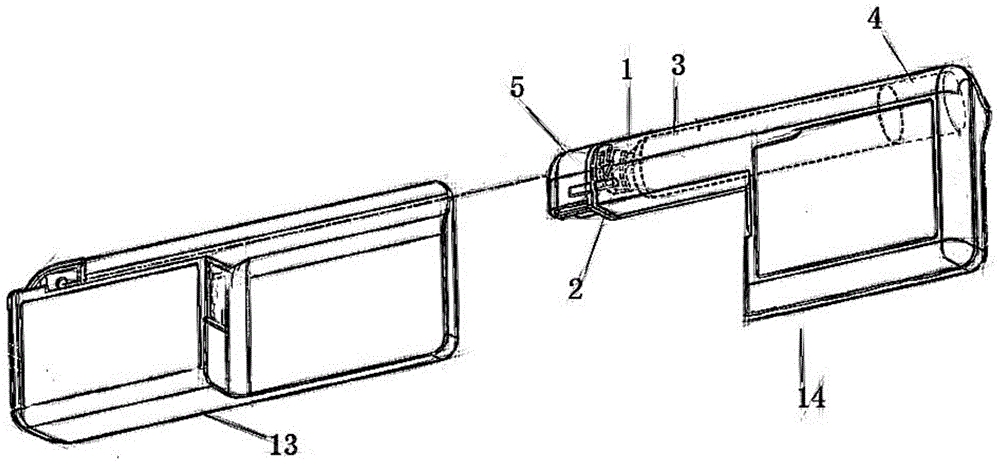
图1是本发明提供的移动医疗装置的组装方式的简化结构示意图;1 is a simplified structural schematic diagram of an assembling method of a mobile medical device provided by the present invention;
图2是本发明提供的第一密封元件与第二密封元件的简化剖视结构示意图;2 is a simplified cross-sectional structural schematic diagram of the first sealing element and the second sealing element provided by the present invention;
图3是本发明提供的移动医疗装置的壳体开放端处的简化剖视结构示意图;和3 is a simplified cross-sectional structural schematic diagram of the open end of the housing of the mobile medical device provided by the present invention; and
图4是本发明提供的将移动医疗装置安装至扶手部上的安装方式的简化结构示意图。FIG. 4 is a simplified structural schematic diagram of the installation method for installing the mobile medical device on the armrest provided by the present invention.
附图标记列表List of reference signs
1:注射泵壳体 2:壳体开放端 3:储药筒1: Syringe pump housing 2: Housing open end 3: Reservoir cartridge
4:泵驱动装置 5:盖合组件 6:轴向微小间隙4: Pump drive 5: Cover assembly 6: Axial micro clearance
7:第一密封元件 8:内侧端面 9:环状凹槽7: First sealing element 8: Inside end face 9: Annular groove
10:第二密封元件 11:第一部分内侧端面 12:第二部分内侧端面10: Second sealing element 11: Inside end face of first part 12: Inside end face of second part
13:控制器装置 14:注射泵装置 15:支撑架13: Controller unit 14: Syringe pump unit 15: Support frame
16:安装架 17:扶手部 18:上端面16: Mounting bracket 17: Armrest 18: Upper end surface
19:保持部 20:承托部19: Holding part 20: Supporting part
具体实施方式Detailed ways
下面结合附图对本发明进行详细说明。The present invention will be described in detail below with reference to the accompanying drawings.
如图1所示出的是本发明所提出的移动医疗装置未组装前的简化结构示意图。该移动医疗装置主要包括控制器装置13和注射泵装置14。本发明中控制器装置13与注射泵装置14形状相适配,两者之间可以通过可拆卸连接的方式进行安装或拆卸更换新的注射泵装置14。其中,注射泵装置14又是由注射泵壳体1以及盖合组件5两个主要部件进行装配所得到的。FIG. 1 is a simplified schematic diagram of the mobile medical device proposed by the present invention before it is assembled. The mobile medical device mainly includes a
如下对本申请所提出的移动医疗装置应用于航空环境下能够在注射泵装置14内部压力与机舱内压力不同的情况下提供压力平衡的具体过程进行说明:The specific process of applying the mobile medical device proposed in the present application to the aviation environment to provide pressure balance when the internal pressure of the
首先,如图1所示,在患者进行给药前,移动医疗装置包括分体设置的控制器装置13、注射泵壳体1以及盖合组件5。继而先将盖合组件5装配至注射泵壳体1上构成注射泵装置14。盖合组件5两端分别与储药筒3内部药液以及输液设备/输液管连通。将注射泵装置14装配至控制器装置13上。控制器装置13上设置有用于用户直接操作的操作界面/显示设备,从而用户可以直接通过操作界面实现对注射泵运作参数的实时准确调控。First, as shown in FIG. 1 , before the patient administers medicine, the mobile medical device includes a
在将盖合组件5沿注射泵壳体1的壳体开放端2,接合至注射泵壳体1上的同时,位于盖合组件5内部的导液通路连通至储药筒3内部。并且,如图3所示,置于盖合组件5端部的环形凹槽内的第一密封元件7与第二密封元件10,被左右两侧的盖合组件5端部外壁以及注射泵壳体1开放端外壁夹紧。When the
如图2所示,针对第二密封元件10上位于环形凹槽外部的部分垫片/外圈部分,在注射泵壳体1与盖合组件5相接合时,其受到轴向压缩力。As shown in FIG. 2 , for a portion of the gasket/outer ring portion of the
由于本申请中第二密封元件10上的内圈部分与第一密封元件7间为抵接关系,而密封垫圈的外圈部分与第一密封元件7间可以是固接关系或是抵接关系。因此,在外圈部分被紧压而内圈部分未受压的情况下,密封垫圈上相对可活动程度较高的内圈部分朝向侧向微微翘起。Since the inner ring part of the
因而在该轴向压缩力的作用下,第二密封元件10上与第一部分内侧端面11所对应的端部与第一密封元件7之间呈非紧密贴合。对两者施加具有压缩趋势的作用力却使得两者非紧密贴合,这里所指的非紧密贴合包括相互接触但相互作用力非常弱的情况,也包括彼此完全不存在接触点的情况。在该设置下,内圈部分的一端微微翘起,第二密封元件10无法对轴向微小间隙所流通至接合位置处的气体形成完全阻隔,轴向微小间隙所流通至接合位置处的气体能够经过第二密封元件10的内圈部分而从第一密封元件7向外流通。在该功能下,达到了垫片对注射泵壳体1与盖合组件5之间的紧固密封作用,并同时提供了注射泵壳体1内部气体流动的通气路径。Therefore, under the action of the axial compressive force, the end of the
进一步地,轴向微小间隙内部的气体即与注射泵壳体1内部的气压一致。该部位的气体能够依次地通过环形凹槽,并从第一密封元件7的内侧端面8进入第一密封元件7内部。基于第一密封元件7中具有高比表面的微孔结构,以防止外部液体进入的方式将气体流通至注射泵壳体1的外部。以此实现了移动医疗装置应用于航空环境下能够在注射泵装置14内部压力与机舱内压力不同的情况下提供压力平衡的作用。Further, the gas inside the axially small gap is the same as the gas pressure inside the
根据一种优选实施方式,如图4所示,为实现注射泵装置14在轮椅上或是在航空环境下的快捷安装使用,本发明还提出了一种能够适应于轮椅或是航空座椅上的扶手部17的移动医疗装置。通常,轮椅上的扶手部17带有平整上端面18,而航空座椅的扶手部17带有弧形上端面18。注射泵装置14的安装要求其所处高度的可调节性以及相对稳定性。According to a preferred embodiment, as shown in FIG. 4 , in order to realize the quick installation and use of the
本发明通过设置预先装配有支撑架15的注射泵装置14、以及分体设置的安装架16,将安装架16固定在其他设备的扶手部17上而可以为注射泵装置14在扶手部17上的安装提供连接位点,因此能够实现快捷安装使用;本发明还通过设置保持部19上的不可见端面与承托部20上的不可见端面,分别与设备扶手部17上相邻的两端面彼此至少部分接触,进一步实现注射泵装置14在扶手部17上的稳定支撑。In the present invention, the
在使用该移动医疗装置之前,该移动医疗装置由彼此分体设置的注射泵装置14和安装架16构成。Before the mobile medical device is used, the mobile medical device is composed of a
注射泵装置14用于通过输注套管将来自储药筒3的药物输送至用户,其外壁上预先装配有支撑架15。The
支撑架15可以是类似于伸缩拉杆式结构,其自由端可以从注射泵装置14外壁上拉出或收回。支撑架15的设置使得注射泵装置14的高度可调。The
在使用该移动医疗装置之前,安装架16具有彼此铰接的保持部19与承托部20,保持部19与承托部20均为板状结构。Before using the mobile medical device, the mounting
承托部20是与扶手部17相适配的长板状,保持部19是相对承托部20更短的可预定的尺寸。由于两者之间铰接为可回复弹性连接,在不施加外力作用的情况下两者之间夹角接近为0°,在使用时两者之间的夹角最大为90°。The receiving
承托部20是用于与扶手部17的侧端面相抵接的用于连接支撑架15的部件,保持部19是用于与扶手部17的上端面18相抵接的用于保持承托部20稳定的部件。The receiving
针对本申请移动医疗装置适应于轮椅或是航空座椅上的扶手部17的功能的实现在于,保持部19是相对承托部20更短的可预定的尺寸。保持部19既可以分别置于扶手部17两侧来对承托部20提供稳定支撑针对轮椅扶手部17,保持部19还可以置于扶手部17中间位置处来对承托部20提供稳定支撑针对航空座椅扶手部17。For the realization of the function of the mobile medical device of the present application being adapted to the
继而先将安装架16装配至其他设备的扶手部17上,该过程中:Then, first assemble the mounting
针对带有平整上端面18的轮椅扶手部17,轮椅扶手部17上通常还设置有提供舒适作用的垫子,垫子两端分别对应保留有部分仍为平整上端面18而非完全弧形面的扶手。For the
安装架16上具有两端分别与保持部19不可见端面以及承托部20不可见端面相固接的环形调节带。调节带具有一定的弹性,且可调节其环形带体的长度。The mounting
以此,先展开彼此闭合紧贴的保持部19以及承托部20,将至少一个环形调节带从扶手部17的开放端套穿在扶手部17上。此时保持部19的不可见端面抵接在扶手部17上端面18,此时承托部20的不可见端面与扶手部17外侧的侧端面相抵接。将环形调节带进一步收短,使得上述不可见端面与扶手部17端面之间的固定作用增强。由此完成安装架16的装配。In this way, the holding
在需要使用该移动医疗装置时,将注射泵装置14外壁上呈收纳状态的支撑架15展开并延长。在延长至需要的长度时固定支撑架15的当前长度,注射泵装置14位于支撑架15的上端,只需将支撑架15安装至已经装配有安装架16的其他设备的扶手部17上,支撑架15下端以可拆卸连接的方式快速地连接至安装架16,以此,将该移动医疗装置稳定安装在了其他设备的扶手部17上。When the mobile medical device needs to be used, the
需要注意的是,上述具体实施例是示例性的,本领域技术人员可以在本发明公开内容的启发下想出各种解决方案,而这些解决方案也都属于本发明的公开范围并落入本发明的保护范围之内。本领域技术人员应该明白,本发明说明书及其附图均为说明性而并非构成对权利要求的限制。本发明的保护范围由权利要求及其等同物限定。It should be noted that the above-mentioned specific embodiments are exemplary, and those skilled in the art can come up with various solutions inspired by the disclosure of the present invention, and these solutions also belong to the disclosure scope of the present invention and fall within the scope of the present invention. within the scope of protection of the invention. It should be understood by those skilled in the art that the description of the present invention and the accompanying drawings are illustrative rather than limiting to the claims. The protection scope of the present invention is defined by the claims and their equivalents.
Claims (10)
Priority Applications (1)
| Application Number | Priority Date | Filing Date | Title |
|---|---|---|---|
| CN202010214134.9A CN111388795A (en) | 2020-03-24 | 2020-03-24 | A mobile medical device suitable for stroke patients |
Applications Claiming Priority (1)
| Application Number | Priority Date | Filing Date | Title |
|---|---|---|---|
| CN202010214134.9A CN111388795A (en) | 2020-03-24 | 2020-03-24 | A mobile medical device suitable for stroke patients |
Publications (1)
| Publication Number | Publication Date |
|---|---|
| CN111388795A true CN111388795A (en) | 2020-07-10 |
Family
ID=71411031
Family Applications (1)
| Application Number | Title | Priority Date | Filing Date |
|---|---|---|---|
| CN202010214134.9A Pending CN111388795A (en) | 2020-03-24 | 2020-03-24 | A mobile medical device suitable for stroke patients |
Country Status (1)
| Country | Link |
|---|---|
| CN (1) | CN111388795A (en) |
Cited By (1)
| Publication number | Priority date | Publication date | Assignee | Title |
|---|---|---|---|---|
| CN113893097A (en) * | 2021-11-05 | 2022-01-07 | 西安国际医学中心有限公司 | Multifunctional analgesia treatment device for treating cancer pain |
Citations (5)
| Publication number | Priority date | Publication date | Assignee | Title |
|---|---|---|---|---|
| EP2327437A1 (en) * | 2009-11-25 | 2011-06-01 | Ricoh Company, Ltd. | Infusion pump module and infusion system |
| US20140025008A1 (en) * | 2012-07-20 | 2014-01-23 | Asante Solutions, Inc. | Pump System and Method |
| CN104114210A (en) * | 2012-02-17 | 2014-10-22 | 森西勒Pat股份公司 | Liquid storage and delivery system |
| CN106604753A (en) * | 2014-08-26 | 2017-04-26 | 比格福特生物医药公司 | Infusion pump system and method |
| CN210096545U (en) * | 2019-03-14 | 2020-02-21 | 深圳迈瑞科技有限公司 | Injection pump |
-
2020
- 2020-03-24 CN CN202010214134.9A patent/CN111388795A/en active Pending
Patent Citations (5)
| Publication number | Priority date | Publication date | Assignee | Title |
|---|---|---|---|---|
| EP2327437A1 (en) * | 2009-11-25 | 2011-06-01 | Ricoh Company, Ltd. | Infusion pump module and infusion system |
| CN104114210A (en) * | 2012-02-17 | 2014-10-22 | 森西勒Pat股份公司 | Liquid storage and delivery system |
| US20140025008A1 (en) * | 2012-07-20 | 2014-01-23 | Asante Solutions, Inc. | Pump System and Method |
| CN106604753A (en) * | 2014-08-26 | 2017-04-26 | 比格福特生物医药公司 | Infusion pump system and method |
| CN210096545U (en) * | 2019-03-14 | 2020-02-21 | 深圳迈瑞科技有限公司 | Injection pump |
Cited By (2)
| Publication number | Priority date | Publication date | Assignee | Title |
|---|---|---|---|---|
| CN113893097A (en) * | 2021-11-05 | 2022-01-07 | 西安国际医学中心有限公司 | Multifunctional analgesia treatment device for treating cancer pain |
| CN113893097B (en) * | 2021-11-05 | 2023-08-18 | 西安国际医学中心有限公司 | Multifunctional pain relieving treatment device for treating cancer pain |
Similar Documents
| Publication | Publication Date | Title |
|---|---|---|
| US4043332A (en) | Constant flow rate liquid medicament administering device | |
| US3942526A (en) | Alarm system for intravenous infusion procedure | |
| TW202026021A (en) | Detection assemblies for infusion pumps | |
| US11166660B2 (en) | Dermally affixed device for intravenous access | |
| WO2013075622A1 (en) | Syringe pump and drive system thereof | |
| CN110448284A (en) | Invasive Pressure Sensor | |
| CN208877539U (en) | A kind of intelligent peristaltic pump | |
| US8827976B2 (en) | System for ambulatory drug infusion comprising a filling apparatus for flexible containers, container assembly, and use of a flexible container | |
| CN111388795A (en) | A mobile medical device suitable for stroke patients | |
| WO2020005107A1 (en) | Syringe infusion pump | |
| EP2371408B1 (en) | Liquid drug degasing devise and ambulatory infusion system including a degasing device | |
| Raghavendra et al. | Intravenous drip meter & controller | |
| CN200998468Y (en) | Automatic alarm infusion device | |
| CN207493022U (en) | It is a kind of conveniently, the transfusion system of accurate measurements infusion flow | |
| EP0975381B1 (en) | Flow indicators for ambulatory infusion | |
| CN209548475U (en) | A non-suspension infusion intelligent monitoring system | |
| CN204766847U (en) | Developments liquid medicine filter for pump | |
| CN204932448U (en) | A kind of infusion set | |
| CN117797359B (en) | Injection pump control system for transdermal administration | |
| CN215231079U (en) | A regulator for controlling the number of intravenous drips | |
| CN205460153U (en) | Venous transfusion auxiliary detection device | |
| CN222426837U (en) | Novel injection pump | |
| CN219558317U (en) | Portable infusion pump and liquid storage box drop detection device | |
| JPH07155373A (en) | Externally provided pump stroke indicatior | |
| CN114949454B (en) | Infusion alarm |
Legal Events
| Date | Code | Title | Description |
|---|---|---|---|
| PB01 | Publication | ||
| PB01 | Publication | ||
| SE01 | Entry into force of request for substantive examination | ||
| SE01 | Entry into force of request for substantive examination |