An object of the present invention is to provide an improved electronic component mounting apparatus.
A first aspect of the present invention provides a kind of electronic component mounting apparatus, and it comprises: the card flask that electronic unit is housed; Be connected in described card flask, be used for providing the flask first and second feeders of electronic unit from card; One is in relation to first installation head of described first feeder, and the suction nozzle of the electronic unit that is used for picking up and then keeps being provided by first feed arrangement is provided for it; One is in relation to second installation head of described second feeder, and the suction nozzle of the electronic unit that is used for picking up and then keeps being provided by second feed arrangement is provided for it; One is used for supporting the table device of a printed circuit board (PCB); Described first and second installation head alternately along a first direction move to table device on a corresponding zone, printed circuit board (PCB) position; Described table device is to be designed to make printed circuit board (PCB) to move along a second direction perpendicular to first direction, and makes described printed circuit board (PCB) round a rotational perpendicular to first and second directions; When first installation head is positioned at when zone, the suction nozzle of described first installation head () moves down, and electronic unit is held in place on the printed circuit board (PCB) on the table device; When second installation head is positioned at when zone, the suction nozzle of described second installation head moves down, and electronic unit is held in place on the printed circuit board (PCB) on the table device; One first electronic unit identification division is used for when described first installation head moves, and surveys the situation of the electronic unit that the suction nozzle by first installation head holds; Before described first installation head was placed on electronic unit on the described printed circuit board (PCB), described table device can respond the situation that is detected by the first electronic unit identification division and printed circuit board (PCB) is rotated; One second electronic unit identification division is used for when described second installation head moves, and surveys the situation of the electronic unit that the suction nozzle by second installation head holds; And before described second installation head was placed on electronic unit on the described printed circuit board (PCB), described table device can respond the situation that is detected by the second electronic unit identification division and printed circuit board (PCB) is rotated;
Second aspect present invention is based on its first aspect, and provide a kind of electronic component mounting apparatus, wherein also comprise: one is connected in the controller of the described first electronic unit identification division, whether the suction nozzle that is used for surveying first installation head fails to pick up electronic unit, and the response output signal that comes from the first electronic unit identification division is surveyed the attitude of the electronic unit that the suction nozzle by first installation head holds; One is used to survey the transducer of the height of the electronic unit that the suction nozzle by first installation head holds; Described controller is connected in the second electronic unit identification division, whether the suction nozzle that is used for surveying second installation head fails to pick up electronic unit, and the response output signal that comes from the second electronic unit identification division is surveyed the attitude of the electronic unit that the suction nozzle by second installation head holds; An and transducer that is used to survey the height of the electronic unit that the suction nozzle by second installation head holds.
Third aspect present invention is based on its first aspect, and provide a kind of electronic component mounting apparatus, wherein table device comprises a motor, one deceleration device that is connected with motor output shaft, one is connected with deceleration device, the workbench that when motor output shaft rotates, also rotates, and one be connected with workbench and be used for the support component of supporting printing board.
Fourth aspect present invention is based on its third aspect, and provide a kind of electronic component mounting apparatus, wherein table device also comprise be used for printed circuit board (PCB) pass from or reach the conveyer of support component, and be used for printed circuit board (PCB) is positioned positioner on the support component.
Fifth aspect present invention is based on its first aspect, and provide a kind of electronic component mounting apparatus, comprise also that wherein one is used for providing printed circuit board feeder to the table device with printed circuit board (PCB), and a printed circuit board translator that is used for transmitting from table device printed circuit board (PCB).
Sixth aspect present invention is based on its 5th aspect, and a kind of electronic component mounting apparatus is provided, and comprises also that wherein a motor and connects the power transmission mechanism of motor and printed circuit board feeder.
Seventh aspect present invention is based on its 5th aspect, and a kind of electronic component mounting apparatus is provided, and wherein the printed circuit board feeder comprises and is used for guiding respectively the guide member of printed circuit board (PCB) opposite side.
Eighth aspect present invention is based on its fourth aspect, and a kind of electronic component mounting apparatus is provided, and comprises also that wherein a motor and connects the power transmission mechanism of the positioner of motor and table device.
Ninth aspect present invention is based on its 5th aspect, and a kind of electronic component mounting apparatus is provided, and wherein also comprises being used for blocking in a pre-position that is higher than table device a brake of the printed circuit board (PCB) that is provided by the printed circuit board feeder.
Tenth aspect present invention is based on its first aspect, and a kind of electronic component mounting apparatus is provided, wherein blocks flask and comprise card flask in bulk that electronic unit in bulk is housed and be equipped with and walk belt card flask with what be placed on chip type electronic unit on the conveyer belt to determining deviation.
The present invention's the tenth one side is based on its first aspect, and provide a kind of electronic component mounting apparatus, wherein when the electronic unit that is provided by first feeder is provided the suction nozzle of first installation head, the suction nozzle of second installation head is placed on electronic unit on the printed circuit board (PCB) on the table device, and, when the electronic unit that is provided by second feeder was provided the suction nozzle of second installation head, the suction nozzle of first installation head was placed on electronic unit on the printed circuit board (PCB) on the table device.
The present invention the 12 aspect is based on its first aspect, and a kind of electronic component mounting apparatus is provided, and wherein corresponding to all interchannel spacing of feeding electronic unit from the card flask spacing between the suction nozzle of first and second installation head is set.
The present invention the 13 aspect is based on its first aspect, and provide a kind of electronic component mounting apparatus, wherein each first and second installation head comprises a motor, one cam part that is connected with motor output shaft, one with the cam follower wheel of cam part engagement, one is connected and supports the plate of suction nozzle with cam follower wheel, suction nozzle is risen or descend.
The present invention the 14 aspect is based on its 13 aspect, and a kind of electronic component mounting apparatus is provided, and wherein also comprises according to cam part control motor output shaft slewing area to change the controller of suction nozzle lower position.
The present invention the 15 aspect is based on its 13 aspect, and a kind of electronic component mounting apparatus is provided, and wherein when the position of suction nozzle during near its upper and lower bound position, the movement velocity of suction nozzle is very low.
The present invention the 16 aspect is based on its 13 aspect, and a kind of electronic component mounting apparatus is provided, and wherein also comprises the controller that is used for controlling the motor output shaft rotating speed.
The present invention the 17 aspect is based on its first aspect, and a kind of electronic component mounting apparatus is provided, and wherein the suction nozzle of first installation head rises simultaneously and descends, and the suction nozzle of second installation head also rises simultaneously and descends.
The present invention's the tenth eight aspect is based on its first aspect, and a kind of electronic component mounting apparatus is provided, and wherein the suction nozzle of first installation head rises continuously and descends with different timing, and the suction nozzle of second installation head rises continuously and descends with different timing.
The present invention the 19 aspect is based on its first aspect, and provide a kind of electronic component mounting apparatus, wherein also comprise: a suction nozzle of selecting from the suction nozzle of first installation head can rise and descend, and a suction nozzle of selecting from the suction nozzle of second installation head can rise and descend.
The present invention the 20 aspect is based on its 19 aspect, and provides a kind of electronic component mounting apparatus, the suction nozzle of wherein not selected first installation head to be under an embargo to rise and descend, and the suction nozzle of not selected second installation head is under an embargo and rises and descend.
The present invention the 20 is on the one hand based on its first aspect, and a kind of electronic component mounting apparatus is provided, and wherein also comprises being connected with first and second installation head being used for pushing away the spring of suction nozzle downwards.
The present invention the 22 aspect is based on its first aspect, and provide a kind of electronic component mounting apparatus, wherein also comprise: the controller that interrelates with the suction nozzle of the first electronic unit identification division and first installation head and the combination of electronic unit remover, be used for surveying each electronic unit and whether normally hold, and be used for an electronic unit that is not normally held by relevant suction nozzle that is detected is taken away from relevant suction nozzle by the relevant suction nozzle of first installation head; And the controller that interrelates with the suction nozzle of the second electronic unit identification division and second installation head and the combination of electronic unit remover, be used for surveying each electronic unit and whether normally hold, and be used for an electronic unit that is not normally held by relevant suction nozzle that is detected is taken away from relevant suction nozzle by the relevant suction nozzle of second installation head.
First embodiment
Consult Fig. 1,2 and 3, the electronic component mounting apparatus in the first embodiment of the invention comprises the hull shape bedframe 1 that the first and second electronic unit feeders 2,3 are set.The first electronic unit feeder 2 is furnished with the card flask 4 that a cover is arranged side by side.The first electronic unit feeder 2 is furnished with card flask 4 is supported in a bonding part 2A on the appropriate location.Under a transmission mechanism related with the first electronic unit feeder 2 helped, each the card flasks 4 in the first electronic unit feeder 2 were designed to feeding electronic unit (electronic component) continuously.Similarly, the second electronic unit feeder 3 also is furnished with cover card flask 4 side by side.The second electronic unit feeder 3 is furnished with card flask 4 is supported in a bonding part 3A on the appropriate location.Under a transmission mechanism related with the second electronic unit feeder 3 helped, each the card flasks 4 in the second electronic unit feeder 3 were designed to feeding electronic unit (electronic component) continuously.The first and second electronic unit feeders 2 and 3 are separated from each other a predetermined interval.The path of the first and second electronic unit feeders 2 and 3 feeding electronic units is that the Y direction in the horizontal plane is extended.
Card flask 4 in the first and second electronic unit feeders 2 and 3 is bulk types or walks belt.Bulk type card flask 4 comprises electronic unit in bulk.Walking belt card flask 4 is equipped with given interval and is fixed on chip type electronic unit on the conveyer belt by removably.
A controller 23 that is supported on the bedframe 1 is controlled different acting devices according to the output signal of different sensors.Controller 23 comprises a microcomputer or a similar equipment, has the equipment of one combinatorial input/output port, a CPU, a ROM and a RAM.Microcomputer is operated according to the program that is stored among the ROM.Therefore controller 23 is operated according to program.
Be supported on a table device 6 on the bedframe 1 in the first and second electronic unit feeders 2 and 3 extensions.One first electronic unit identification division 12 is between the first electronic unit feeder 2 and table device 6.The first electronic unit identification division 12 is used for surveying the state of the electronic unit (electronic component) that is held by suction nozzle.The signal of telecommunication of the electronic unit state that holds by suction nozzle that the first electronic unit identification division 12 detects to controller 23 output one expression.The first electronic unit identification division 12 comprises that one takes the camera (or a line sensor) of each electronic unit image that is held by suction nozzle to the camera of each electronic unit image that is held by suction nozzle of photographs and a level.The output signal of the controller 23 responses first electronic unit identification division 12, thus whether identification electronic unit and electronic unit are normally held by suction nozzle.Therefore whether controller 23 decision suction nozzles fail to pick up electronic unit.
One second electronic unit identification division 13 is between the second electronic unit feeder 3 and table device 6.The second electronic unit identification division 13 is as the situation of surveying the electronic unit (electronic component) that is held by suction nozzle.The signal of telecommunication of the electronic unit situation that holds by suction nozzle that the second electronic unit identification division 13 detects to expression of controller 23 output.The second electronic unit identification division 13 comprises that one takes the camera (or a line sensor) of each electronic unit image that is held by suction nozzle to the camera of each electronic unit image that is held by suction nozzle of photographs and a level.The output signal of the controller 23 responses first electronic unit identification division 12, thus whether identification electronic unit and electronic unit are normally held by suction nozzle.Therefore whether controller 23 decision suction nozzles fail to pick up electronic unit.
One rejected part is removed part 17 between the table device 6 and the first electronic unit identification division 12.Rejected part is removed part 17 and is used for removing from the course feed passage being judged or being found to be the electronic component that is not normally held by suction nozzle.One rejected part is removed part 18 between the table device 6 and the second electronic unit identification division 13.Rejected part is removed part 18 and is used for removing from the course feed passage being judged or being found to be the electronic component that is not normally held by suction nozzle.
Table device 6 is used for fixing a printed circuit board (PCB) 19 at its upper surface.Table device 6 is supported on the pair of guide rails 7 slidably.The output shaft of drive motor 14 combines with table device 6 by a ball screw 5.When drive motor 14 rotated, table device 6 slided along guide rail 7, and along the Y direction at horizontal in-plane moving, promptly by the direction of the first and second electronic unit feeders 2 and 3 feeding electronic units.According to controller 23 controlling and driving motor 14.Thereby can be by controller 23 Control work table apparatus 6.
First and second installation head 10 and 11 are supported slidably by one or a few guide rail 8, and guide rail is arranged on the lower surface of the upper-part (entablature) 9 of fixedlying connected with bedframe 1.All be fixed with a plurality of mobilizable suction nozzles (mobilizable vacuum slot or pick up suction nozzle) 20 in each first and second installation head 10 and 11.By the suitable acting device that the output signal of controller 23 is controlled, can make suction nozzle 20 rise or descend with respect to first and second installation head 10 and 11 main bodys.First and second installation head 10 and 11 can be slided along guide rail 8, and move on the directions X of level.Directions X is vertical with the Y direction, and is promptly vertical with the direction of 3 feeding electronic units with the first and second electronic unit feeders 2.First and second installation head 10 and 11 are driven by a suitable acting device, and this acting device is by the output signal control of controller 23.Thereby, controller 23 may command, first and second installation head 10 and 11.First and second installation head 10 and 11 can be moved independently of each other.
First installation head 10 is by controller 23 controls, along directions X reciprocating motion between first and second positions.When first installation head 10 during in primary importance, the suction nozzle 20 on first installation head 10 picks up electronic unit from the first electronic unit feeder 2.The second place of first installation head 10 is corresponding to the position of a printed circuit board (PCB) 19 on the table device 6.
The arrangement pitch of all suction nozzles 20 on first installation head 10 is equivalent to all interchannel spacing that electronic unit enters the first electronic unit feeder 2 from card flask 4.Specifically, the spacing of 20 of all suction nozzles equates with all interchannel spacing that electronic unit is sent out from the first electronic unit feeder 2 on first installation head 10.The spacing of 20 of all suction nozzles can equate with the integral multiple of all interchannel spacings that electronic unit is sent out from the first electronic unit feeder 2 on first installation head 10.
Second installation head 11 is by controller 23 controls, along directions X reciprocating motion between first and second positions.When first installation head 10 during in primary importance, the suction nozzle 20 on second installation head 11 picks up electronic unit from the first electronic unit feeder 2.The second place of second installation head 11 is corresponding to the position of a printed circuit board (PCB) 19 on the table device 6.
The arrangement pitch of all suction nozzles 20 on second installation head 11 is equivalent to all interchannel spacing that electronic unit enters the second electronic unit feeder 3 from card flask 4.Specifically, the spacing of 20 of all suction nozzles equates with all interchannel spacing that electronic unit is sent out from the second electronic unit feeder 3 on second installation head 11.The spacing of 20 of all suction nozzles can equate with the integral multiple of all interchannel spacings that electronic unit is sent out from the second electronic unit feeder 3 on second installation head 11.
One loader 15 is controlled so that a printed circuit board (PCB) 19 is sent to table device 6 by controller 23.One emptier 16 is controlled so that printed circuit board (PCB) 19 is transported out of table device 6 by controller 23.Card flask 4 in the first electronic unit feeder 2 is driven by feed arrangement 21.Card flask 4 in the second electronic unit feeder 3 is driven by feed arrangement 22.
The first and second electronic unit identification divisions 12 have similar structure with 13.Therefore only the first electronic unit identification division 12 and relevant parts are explained.Shown in Figure 4 and 5, the first electronic unit identification division 12 comprises that one is supported on the camera 27 on the bedframe 1.Specifically, camera 27 is fixed on the side of I type support 25, and the upper surface of I type support and bedframe 1 is fixed.Camera 27 is arranged up.Camera 27 has a barrel 26.The axle 24 that is supported on first installation head, 10 main bodys is extended downwards by the main body of first installation head 10.All suction nozzles 20 are connected with all axles 24 respectively.All suction nozzles 20 extend from the lower ends downward of all axles 24 respectively.Camera 27 is taken the image of the electronic unit 150 that is held by suction nozzle 20 continuously.The signal of electronic unit 150 images that camera 27 is held by suction nozzle 20 to controller 23 output one expression.One line sensor 28 is fixed with the upper surface of I type support 25.Line sensor 28 has a housing or main body, and this housing is made up of the groove 28A that can hold suction nozzle 20.Groove 28A extends along the direction identical with suction nozzle 20 directions of motion.Therefore, suction nozzle 20 can move along groove 28A.Line sensor 28 is surveyed the height of the electronic unit 150 that is held by suction nozzle 20 in succession.The signal of telecommunication of electronic unit 150 height that hold by suction nozzle 20 that line sensor 28 detects to controller 23 output one expression.
Consult Fig. 6,7 and 8, table device 6 comprises one by the Y workbench 29 that is fixed on linear guide device 31 sliding supports on the table base 30.Linear guide device 31 is corresponding with guide rail 7 among Fig. 1.Table base 30 is fixed with bedframe 1 (see figure 2).The output shaft of Y-axis motor 32 combines with Y workbench 29 by a ball screw 33.Y-axis motor 32 is corresponding to the drive motor among Fig. 3 14.Ball screw 33 is corresponding to the ball screw among Fig. 35.When the output shaft of Y-axis motor 32 rotated, Y workbench 29 moved along the Y direction.Y workbench 29 can move back and forth along the Y direction.Y-axis motor 32 is by the output signal control of controller 23 (see figure 1)s.Therefore Y workbench 29 can be by controller 23 controls.
With the fixing transducer 39 of table base 30 according to the initial point of Y workbench 29 with respect to the position sensing Y-axis of table base 30.Initial point acquisition sensor 39 comprises the signal of telecommunication of the former dot information of Y-axis that goes out with respect to the position sensing of table base 30 according to the Y workbench to controller 23 (see figure 1)s output one.In the position corresponding to the Y initial point, a Y initial point detecting plate 40 is fixing with Y workbench 29.When Y initial point detecting plate 40 was moved into the position aimed at origin sensor 39 and is detected by origin sensor 39, the output signal of origin sensor 39 was taked the state that shows that Y workbench 29 is consistent with the Y initial point with respect to the position of table base 29.
Table device 6 comprise one with fixing θ framework or the θ workbench 34 of the output shaft of deceleration device 35.Deceleration device 35 have one with the fixing housing of Y workbench 29.An example of deceleration device 35 is reduction gear boxes.The power shaft of deceleration device 35 combines with the output shaft of θ axle motor 36, motor 36 have one with the fixing housing of Y workbench 29.Therefore, θ framework 34 is connected with θ axle motor 36 by deceleration device 35.When the output shaft of θ axle motor 36 rotated, θ framework 34 rotated (being that θ framework 34 moves along a θ direction) with respect to Y workbench 29 in horizontal plane.Specifically, θ framework 34 can rotate round an axle perpendicular to directions X and Y direction.Can be by the output signal control θ axle motor 36 of a controller 23 (see figure 1)s.Therefore θ framework 34 can be controlled by controller 23 (see figure 1)s.θ framework 34 can one moves along the Y direction with Y workbench 29.
One with Y workbench 29 fixed sensing 37 survey the θ initial point according to θ framework 34 with respect to the obliquity of Y workbench 29.When θ framework 34 rotated with respect to Y workbench 29, former point probe 37 kept static with respect to Y workbench 29.Origin sensor 37 comprises the former dot information of θ that detects with respect to the obliquity of Y workbench 29 according to θ framework 34 at the interior signal of telecommunication to controller output one.θ initial point detecting plate 38 rotates with θ framework 34.Aim at origin sensor 37 or positions aligning and when being detected by origin sensor 37 when θ initial point detecting plate 38 rectilinear motions enter, the output signal of origin sensor 37 is taked the obliquity state consistent with the θ initial point of an expression θ framework 34 relative Y workbench 29.
When by vertically extending guider 42 guiding that is fixed on the θ framework 34, a track-frame 41 can move both vertically.Track-frame 41 is driven by an acting device or a power cylinder 43, acting device or power cylinder have one with the fixing housing of table base 30.Track-frame 41 can move up and down in the position corresponding to the Y-axis initial point.Output signal control power cylinder 43 according to controller 23 (see figure 1)s.Thereby track-frame 41 can be by controller 23 control (see figure 1)s.For example a power cylinder 43 is one to be connected the pneumatic cylinder by the control of controller 23 (see figure 1)s with electromagnetically operated valve.
In the hole that vertically extending support pin 44 embeds on the θ framework 34.When track-frame 41 moved downward, support pin 44 supported a printed circuit board (PCB) 19.The main body of bearing 45 and track-frame 41 are fixing.One fixing transmission track 47 is set on each bearing 45.One belt guide pulley 48 is supported on the fixing transmission track 47.Belt guide pulley 48 engages with a feed belt 46, and the power drive that belt 46 can be applied by an outside is to transmit printed circuit board (PCB) 19.When driving feed belt 46, it is by 47 guiding of fixing transmission track.
One movable transmission track 49 is parallel to fixedly, and transmission track 47 extends.Movable transmission track 49 guiding one feed belt 50 that engages with belt guide pulley 48.Belt guide pulley 48 is supported on the movable transmission track 49.The power drive that feed belt 50 can be applied by an outside is used for transmitting printed circuit board (PCB) 19.Movable transmission track 49 is fixing with nut 52, nut and ball screw 51 engagements that are arranged on the track-frame 41.When ball screw 51 rotated, movable transmission track 49 was towards fixing transmission track 47 or leave fixedly that transmission track 47 moves.Usually, the position that can adjust movable transmission track 49 according to the size or the width of printed circuit board (PCB) 19.When the opposite side of printed circuit board (PCB) 19 was supported by belt, printed circuit board (PCB) 19 can be transmitted by feed belt 46 and 50.
According to fixing moving both vertically of transmission track 47 and movable transmission track 49, belt transmission rotatable parts that are supported on the bar 69 (wherein one only is shown in Fig. 6) can combine with belt guide pulley 48 or break away from.When the rotatable parts on bar 69 combined with belt guide pulley 48, rotatable parts rotating belt guide pulley 48 was so that feed belt 46 and 50 motions.When rotatable parts on the bar 69 and 48 disengagings of belt guide pulley, belt guide pulley 48 no longer is subjected to the effect of revolving force.Therefore belt guide pulley 48 stop motions, also stop motion of feed belt 46 and 50 simultaneously.
Ball screw 51 is perpendicular to fixedly transmission track 47 and movable transmission track 49.Pulley 53 is fixed with the end of ball screw 51 respectively.Connect pulley 53 by a speed-governing belt 54.Thereby by combining of pulley 53 and speed-governing belt 54, ball screw 51 interconnects.When one of them ball screw 51 rotated, another ball screw 51 also rotated.
As previously mentioned, bearing body 45 is fixing with track-frame 41.Support one 55 rotationally by bearing 45.Backstay 57,58 and 59 is supported on the axle 55.Backstay 57,58 and 59 has the pin 56 that is used to locate printed circuit board (PCB) 19.Backstay 57 and 58 provides the benchmark of location printed circuit board (PCB) 19.The position of backstay 59 can be adjusted with respect to axle 55.Set the position of backstay 59 according to the size of printed circuit board (PCB) 19.
One control lever 60 is fixed with the right part of axle 55.When track-frame 41 is positioned at the position of a rising, can drive or rotation control rods 60 by an external impetus transmission part 61.External impetus transmission part 61 is connected with an acting device or a power cylinder (not having reference number) of being controlled by the output signal of controller 23 (see figure 1)s.Thereby control lever 60 can be controlled by controller 23 (see figure 1)s with external impetus transmission part 61.When by external impetus transmission part 61 rotation control rods 60, backstay 57,58 and 59 also rotates, and therefore discharges printed circuit board (PCB) 19.One tension spring 62 is connected with control lever 60.When control lever 60 separated with external impetus transmission part 61, tension spring 62 made control lever 60 return its initial position.Simultaneously, backstay 57,58 and 59 returns the initial position of their supporting printing boards 19.
One detecting plate 63 is fixing with control lever 60.Can survey detecting plate 63 by the transducer (not shown) that is arranged on another unit.Transducer exports a signal that comprises control lever 60 positional informations (just backstay 57,58 and 59 positional information) to controller 23 (see figure 1)s.This information representation printed circuit board (PCB) 19 is to be fixed by backstay 57,58 and 59, has still broken away from backstay 57,58 and 59.
One brake 64 is arranged on the support frame 67 of fixing with bedframe 1 (see figure 1) rotationally.Brake 64 can be driven by an acting device or a power cylinder 65, and acting device or power cylinder have one and pass through the housing that a pin 66 is connected with support frame 67.Brake 64 can rotate along the indicated direction of arrow among Fig. 6 " A ".Power cylinder 65 is by the output signal control of controller 23 (see figure 1)s.Therefore brake 64 can be controlled by controller 23 (see figure 1)s.For example power cylinder 65 is pneumatic cylinders that are connected with the electromagnetically operated valve of being controlled by controller 23 (see figure 1)s.As previously mentioned, printed circuit board (PCB) 19 is transmitted by feed belt 46 and 50.Brake 64 is used for making the position stop motion of printed circuit board (PCB) 19 in a regulation.One with support frame 67 fixed sensing be used for surveying the position whether a printed circuit board (PCB) 19 is positioned at regulation.The output signal of one transducer 68 is sent into controller 23 (see figure 1)s.
As previously shown, according to procedure operation controller 23 (see figure 1)s.Program has NC (numerical control) block that is used for electronic unit placed or be installed on the printed circuit board (PCB) 19 that is positioned on the table device 6.Simultaneously, program has a block that is used for Control work table apparatus 6.According to the workbench control program section of program, table device 6 can be operated as follows.After electronic unit had been placed or be installed on the printed circuit board (PCB) 19, controller 23 made Y workbench 29 and θ framework 34 return their corresponding separately initial positions according to the output signal control Y-axis motor 32 and the θ axle motor 36 of transducer 37 and 39.Subsequently, controller 23 control power cylinders 43 make framework 41 raise.Therefore, by the upper surface of the feed belt 46 of fixing transmission track 47 and 49 guiding of movable transmission track be moved upward to one with the loader 15 and the effective identical position of level of emptier 16 (seeing Fig. 1,2 and 3) of printed circuit board (PCB) 19, printed circuit board (PCB) is positioned at the left side and the right side of table device 6.Then, controller 23 control external impetus transmission parts 61 make external impetus transmission part 61 rotation control rods 60.Printed circuit board (PCB) 19 breaks away from backstay 57,58 and 59 as a result.
When track-frame 41 raise, belt guide pulley 48 combined with rotatable parts on the bar 69, and belt guide pulley 48 is rotated according to the rotation of the rotatable parts on the bar 69.Thereby feed belt 46 and 50 motions transmit the position that printed circuit board (PCB) 19 leaves regulation.When transducer 68 notification controllers 23 printed circuit board (PCB)s 19 were not on assigned position, controller 23 control power cylinders 65 made brake 64 enter the feeding passage of a printed circuit board (PCB) 19.
Then, the new printed circuit board (PCB) 19 (seeing Fig. 1,2 and 3) that is provided by loader 15 is provided feed belt 46 and 50.When making 19 motions of new printed circuit board (PCB) by feed belt 46 and 50, new printed circuit board (PCB) 19 meets with brake 64, stops on the position of regulation subsequently.When new printed circuit board (PCB) 19 arrived assigned position, transducer 68 predicted new printed circuit board (PCB) 19 and is positioned at assigned position.Controller 23 descends track-frame 41 according to the output signal control power cylinder 43 of transducer 68.When track-frame 41 descended, the rotatable parts on belt guide pulley 48 and the bar 69 broke away from.Thereby make feed belt 46 and 50 stop motions.Simultaneously, controller 23 breaks away from external impetus transmission pole 61 and control lever 60 according to the output signal control external impetus transmission pole 61 of transducer 68.Thereby tension spring 62 makes backstay 57,58 and 59 fixing new printed circuit board (PCB)s 19.In this method, new printed circuit board (PCB) 19 is positioned on the suitable position.The printed circuit board (PCB) 19 new in conjunction with the transducer notification controller of detecting plate 63 has been positioned at suitable position.Controller 23 control power cylinders 65 make brake 64 return its idle position or its static position then.Controller 23 control power cylinders 43 make track-frame 41 drop to a given position subsequently.
When printed circuit board (PCB) 19 is replaced by a new printed circuit board (PCB) by this method, electronic unit is placed or is installed on the new printed circuit board (PCB) 19 according to program NC block.In the electronic unit installation process, according to the output signal of the first and second electronic recognition parts 12 and 13, the attitude of the electronic unit that controller 23 decision is held by suction nozzle 20.In addition, according to the attitude that is determined, controller 23 calculates the position correction value of the new printed circuit board (PCB) 19 of each electronic unit.In addition, according to the correction value that calculates, controller 23 is modified to a secondary ideal position with first ideal position of a new printed circuit board (PCB) 19 of each electronic unit.In the electronic unit installation process, controller 23 control Y-axis motor 32 and θ axle motor 36 move to and each corresponding position, electronic unit secondary ideal position new printed circuit board (PCB) 19.In the electronic unit installation process, the suction nozzle 20 on first and second installation head 10 and 11 is placed electronic unit or be installed on the new printed circuit board (PCB) 19.After electronic unit had been placed or be installed on the new printed circuit board (PCB) 19, controller 23 made Y workbench 29 and θ framework 34 be back to initial separately corresponding position.Repeat these orderly processes termly.
Suction nozzle 20 is limited to motion up and down with respect to the motion of first and second installation head 10 and 11 main bodys.Do not allow suction nozzle 20 to rotate.This design of suction nozzle can obtain a bearing with excellent durability that is used for suction nozzle 20.
Consult Fig. 9, be used for the transmission emptier 16 that printed circuit board (PCB) 19 is sent out table device 6 comprise one with the fixing emptier base 70 of bedframe 1 (see figure 1).Emptier 16 also comprises fixedly a transmission track 71 and a movable transmission track 7 that is used for transmitting a printed circuit board (PCB) 19.Fixedly transmission track 71 and movable transmission track 72 all are positioned at the upper surface of emptier base 70.Fixedly transmission track 71 and movable transmission track 72 are parallel to each other.Movable transmission track 72 can be on pair of guide rails 73 towards or leave fixedly transmission track 71 slips.The position of movable transmission track 72 can be adjusted according to the size and the width of printed circuit board (PCB) 19.All guide rails 73 are parallel to each other.The output shaft of drive motor 74 is connected with a pulley 75.One pulley 76 is arranged on the emptier base 70 rotationally.By a belt 77 pulley 75 and 76 is coupled together.Movable transmission track 72 is fixing with belt 77 by a junction spare 78.When drive motor 74 rotary pulleys 75, belt 77 motions, and movable transmission track 72 is also with respect to fixedly transmission track 71 motions.
Fixedly transmission track 71 is used for guiding a feed belt 80.One motor 79 drives feed belt 80 by a transmission mechanism 81.In addition, motor 79 drives and the fixing feed belt 46 that is connected of transmission track 47 of table device 6 by driving mechanism 81.
Movable transmission track 72 is used for guiding a feed belt 83.One motor 82 drives feed belt 83 by a transmission mechanism 84.In addition, motor 82 drives the feed belt 50 that is connected with table device 6 movable transmission tracks 49 by driving mechanism 84.
Driving mechanism 81 and 84 has similar structure.Therefore only describe driving mechanism 81 and relevant parts in detail.As shown in figure 10, driving mechanism 81 comprise one with the fixing roller 85 of the output shaft of motor 79.Driving mechanism 81 comprises that also one passes through the roller 85 that belt 86 is connected with roller 85.When roller 85 was driven by motor 79, belt 86 motions and roller 87 rotated.Belt guide pulley 48 in table device 6 is movable to be entered or breaks away from roller 87.When belt guide pulley 48 was moved into roller 87 and engages, belt guide pulley 48 rotated according to the rotation of roller 87.When the belt guide pulley motion broke away from roller 87, belt guide pulley 48 no longer was subjected to the effect of revolving force.Roller 87 is supported on the bar 69.Belt guide pulley 48 is according to move both vertically (being moving both vertically of track-frame 41) of roller 87, towards or leave the roller motion.When roller 87 engaged with belt guide pulley 48, a tension spring 88 that is connected with bar 69 was pushed roller 87 to belt guide pulley 48.
As shown in figure 11, driving mechanism 81 comprise one with the fixing gear 89 of the output shaft of motor 79.Driving mechanism 81 also comprises a gear 90 and a pulley 91.Gear 90 and gear 89 engagements.Gear 89 and pulley 91 are all fixing with a common axle.Feed belt 80 is supported by pulley 91 and pulley 92.Pulley 92 is supported on the fixedly opposed end of transmission track 71 (see figure 9)s respectively.When motor 79 during along " E " direction driven wheel 89, gear 90 and pulley 91 rotate along the direction of " G ".Move along direction " F " according to the rotation of pulley 91 in the top of one feed belt 80.
Consult Fig. 9 and 12,, moved in the top of belt 77 along direction " C " by drive motor 74 for a big width printed circuit board (PCB) 19.By link 79, with the fixing movable rail 72 in belt top according to of the motion of belt 77 tops along " C " direction, leave fixedly transmission track 71 along guide rail 73.For a little width printed circuit board (PCB) 19, moved in a top of belt 77 along direction " D " by drive motor 74.Movable rail 72 is according to the motion of belt 77 tops along " D " direction, moves along guide rail 73 towards fixing transmission track 71.
In an off time of transmitting printed circuit board (PCB) 19, as shown in figure 13, track-frame 41 and belt guide pulley 48 are positioned at the position that they raise.In another off time, as shown in figure 10, track-frame 41 and belt guide pulley 48 are positioned at the position that they descend.Consult Figure 10 and 13, when moving upward, belt guide pulley 48 meets with the roller 87 of driving mechanism 81.When the contact portion 87a of the contact portion 48a of belt guide pulley 48 and roller 87 met, the tension spring that is connected with roller 87 by bar 69 absorbed the vibrations on the roller 87.When motor 79 during, belt 86 motions, and roller 87 is rotated along direction " E " rotary roller 85.When the contact portion 87a of roller 87 maintenance engaged with the contact portion 48a of belt guide pulley 48, belt guide pulley 48 rotated according to the rotation of roller 87.When belt guide pulley 48 rotates, feed belt 46 motions in the table device 6.
First and second installation head 10 have similar structure with 11.So only describe first installation head 10 in detail.As shown in figure 14, installation head comprises a plurality of movable axis 94 of supporting all suction nozzles 20 respectively.Movable axis 94 straight line.Movable axis 94 is connected with a supporter 96 that is fixed on the installation head framework 95 movably.Movable axis 94 can move up or down with respect to the direction of principal axis of supporter 96 along it.Suction nozzle 20 moves both vertically with movable axis 94.The pin of fixing with supporter 96 97 engages with movable axis 94 respectively.Pin 97 prevents that movable axis 94 from making circumference and rotating.
First installation head 10 comprises that one has the motor 98 of the housing of fixing with installation head framework 95.Output signal control motor 98 according to controller 23 (see figure 1)s.One cam 99 is fixed with the output shaft of motor 98.Cam follower wheel 100 and cam 99 engagements.By a slider 101, the plate 102 that cam follower wheel 100 and is supported on the installation head framework 95 movably is connected.Plate 102 can move up or down with respect to installation head framework 95.One has the groove that the upper end that can make movable axis 94 respectively embeds with the fixing meshing part 103 of plate 102.All compression springs 104 push away all movable axis 94 respectively downwards.By block 106, acting device or solenoid 105 are connected with the upper end of movable axis 94 respectively.Output signal by controller 23 (see figure 1)s is controlled solenoid 105.
Consult Figure 14,15 and 16, when motor 98 rotating cams 99, cam follower wheel 100 moves down and plate 102 also moves down.As shown in figure 17, when plate 102 is positioned at its uppermost position, movable axis 94 also is positioned at their uppermost positions.When solenoid 105 was in the state that they open, solenoid 105 was fixed them at movable axis uppermost position place.When solenoid 105 was in their closure states, movable axis 94 can move up or down.Consult Figure 18, when solenoid 105 was in closure state, when plate 102 and meshing part 103 moved downward, meshing part 103 was to pressing down tension spring 104, and movable axis 94 is moved downward.Consult Figure 19, be in their open modes at solenoid 105, when plate 102 and meshing part 103 moved downward, meshing part 103 was to pressing down tension spring 104, but movable axis 94 still remains on their uppermost positions.Therefore, when relevant solenoid 105 is in closed and open mode respectively, move downward (the moving both vertically) that just can allow or forbid every movable axis 94 selectively.In other words, by controlling relevant solenoid 105, but every movable axis 94 can change between driving condition and inactive state.As shown in figure 20, by suitably controlling solenoid 105, any movable axis 94 all can move downward.
As noted earlier, suction nozzle 20 moves both vertically with movable axis 94.Slewing area with respect to cam 99 control motor 98 output shafts can make controller 23 (see figure 1)s have the function that changes suction nozzle 20 lower positions.
When if solenoid 105 is in closure state, along with the rotation of cam 99, movable axis 94 moves downward.Consult Figure 21, when being under the state of cam 99 with constant speed rotation, As time goes on, each movable axis 94 increases downward displacement with a speed that changes.The design of the shape of cam 99 or profile make when movable axis 94 near its uppermost position or during its bottom position, the vertical speed of movable axis 94 descends.This design can be lenitively, lightly electronic unit 150 is installed on the printed circuit board (PCB) 19.The shape of cam 99 or profile preferably can provide movable axis 94 very average vertical speed.
The thickness of electronic unit 150 is depended in the lower position of each movable axis 94.The first and second electronic unit identification divisions 12 and 13 thickness notification controllers 23 with electronic unit 150.Preferably according to the thickness of electronic unit 150 velocity of rotation, to regulate the vertical speed of movable axis 94 by controller 23 control motor 98.According to the adjusting of movable axis 94 vertical speed, electronic unit 150 can be installed on the printed circuit board (PCB) 19 lightly.
To explain the whole operation of electronic component mounting apparatus below.The whole operation of electronic component mounting apparatus is controlled by controller 23 (see figure 1)s.As shown in figure 22, when second installation head 11 is placed on electronic unit 150 on the printed circuit board (PCB) 19 on the table device 6, first installation head 10 makes first installation head 10 move in the one and first electronic unit feeder 2 with respect to the precalculated position of blocking flask 4 along directions X by controller 23 controls.Feed arrangement 21 starts the bar (not shown) of card flask 4.Thereby open its valve.Controller 23 controls first installation head 10 makes the suction nozzle 20 above it move downward, and by the electronic unit 150 in the approaching card of the opened valve flask 4.Being installed in suction nozzle 20 on first installation head 10 picks up electronic unit 150 and moves upward then.
Subsequently, as shown in figure 23, controller 23 controls first installation head 10 makes the installation head 10 of winning move to the first electronic unit identification division 12 along directions X.Should be understood that it is that suction nozzle 20 by on first installation head 10 holds electronic unit 150.The first electronic unit identification division 12 is surveyed the situation of the electronic unit 150 that is held by the suction nozzle on first installation head 10.The situation of the electronic unit 150 that detects comprises the height and the attitude of electronic unit 150.The advisory controller 23 of the electronic unit 150 that the suction nozzle 20 by on first installation head 10 that the first electronic unit identification division 12 will detect holds.Controller 23 calculates the error between the position that predetermined reference position and each electronic unit 150 detected.Controller deposits the data of the site error that expression calculates among the inner RAM in.
As shown in figure 24, after second installation head 11 has been finished the electronic unit installation process,, make second installation head 11 move apart the position of table device 6 tops by controller 23 controls second installation head 11.Simultaneously, make the installation head 10 of winning move to the top position of table device 6 along directions X by controller 23 controls first installation head 10.For each electronic unit 150, controller 23 is according to the position of site error Control work table apparatus 6 tops first installation head 10 that calculates.Then, the suction nozzle 20 on controller 23 controls first installation head 10 makes suction nozzle 20 move down certain distance according to the height of the electronic unit 150 that detects.Suction nozzle 20 on first installation head 10 is placed electronic unit or be installed on the printed circuit board (PCB) 19.When the complete electronic unit installation process of first installation head 10, controller 23 controls second installation head 11 makes second installation head 11 move in one and the second electronic unit feeder 3 with respect to the precalculated positions of blocking flask 4 along directions X.Thereby feed arrangement 22 starts the bar (not shown) of card flask 4 opens its valve.Controller 23 control second installation head 11 make the suction nozzle 20 above it move downward and by the valve opened near the electronic unit 150 in the card flask 4.Suction nozzle 20 on second installation head 11 picks up electronic unit 150 and moves upward then.
Subsequently, as shown in figure 25, controller 23 controls second installation head 11 makes second installation head 11 move to the second electronic unit identification division 13 along directions X.Should be pointed out that it is that suction nozzle 20 by on second installation head 11 holds electronic unit 150.The second electronic unit identification division 13 is surveyed the situation of the electronic unit 150 that is held by the suction nozzle on second installation head 11.The situation of the electronic unit 150 that detects comprises the height and the attitude of electronic unit 150.The advisory controller 23 of the electronic unit 150 that the suction nozzle 20 by on second installation head 11 that the second electronic unit identification division 13 will detect holds.Controller 23 calculates the error between the position that predetermined reference position and each electronic unit 150 detected.Controller deposits the data of the site error that expression calculates among the inner RAM in.
What these processes were orderly regularly carries out repeatedly, makes electronic unit 150 to be installed on the printed circuit board (PCB) 19 continuously by first and second installation head 10 and 11.First and second installation head 10 and 11 are alternately finished the electronic unit installation process.
As noted earlier, the defective electronic component 150 that is held by the suction nozzle 20 on first and second installation head 10 and 11 is removed part 17 and 18 by rejected part and is moved apart normal feeding passage.It is similar each other that the rejected part relevant with rejected part removal part 17 and 18 removed process.So only explanation and rejected part are removed the relevant rejected part removal process of part 17 below.
As shown in figure 26, when second installation head 11 is placed on electronic unit 150 on the printed circuit board (PCB) 19 on the table device 6, by controller 23 control first installation head 10 make win installation head 10 along directions X move to the first electronic unit feeder 2 in the precalculated position with respect to card flask 4, therefore its valve is opened.By controller 23 control first installation head 10 make suction nozzle 20 above it move downward and by opened valve near electronic unit 150.Suction nozzle 20 on first installation head 10 picks up electronic unit 150 and moves up.
Subsequently, as shown in figure 27, controller 23 controls first installation head 10 makes the installation head 10 of winning move to the first electronic unit identification division 12 along directions X.Should be pointed out that it is that suction nozzle 20 by on first installation head 10 holds electronic unit 150.The first electronic unit identification division 12 is surveyed the situation of the electronic unit 150 that is held by the suction nozzle on first installation head 10.The situation of the electronic unit 150 that detects comprises the height and the attitude of electronic unit 150.The advisory controller 23 of the electronic unit 150 that the suction nozzle 20 by on first installation head 10 that the first electronic unit identification division 12 will detect holds.Controller 23 judges whether that the suction nozzle 20 on first installation head 10 fails to hold electronic unit 150 according to the situation of detected electronic unit 150.When it judges that suction nozzle 20 on first installation head 10 fails to hold electronic unit 150, by controller 23 controls first installation head 10, the installation head 10 of winning is returned and the first electronic unit feeder, 2 interior precalculated positions with respect to card flask 4 from the first electronic unit identification division 12.Then, make the installation head 10 of winning repeat the process of picking up electronic component 150 the card flask 4 in the first electronic unit feeder 2 by controller 23 control first installation head 10.Subsequently, make the installation head 10 of winning move to the first electronic unit identification division 12 again by controller 23 controls first installation head 10.The first electronic unit identification division 12 is surveyed the situation of the electronic unit 150 that is held by the suction nozzle 20 on first installation head 10.As long as the suction nozzle 20 on first installation head 10 fails to hold electronic unit 150, orderly carry out above process termly repeatedly, and controller 23 calculates the number of times of repetition.When the number of times that repeats reached a predetermined value, controller 23 showed an information on its display.This information means that electronic unit 150 has all been got and is over.
Controller 23 judges according to the situation of the electronic unit 150 that has detected whether electronic unit 150 is normally held by suction nozzle 20 relevant on first installation head 10.When its judgement has at least an electronic unit 150 normally not held by the relevant suction nozzle 20 on first installation head 10, make the installation head 10 of winning move to a rejected part shown in Figure 28 by controller 23 controls first installation head 10 and remove part 17.The electronic unit 150 that the installation head 10 of winning will normally not held by controller 23 controls first installation head 10 is discharged into rejected part and removes part 17 then.Subsequently, by controller 23 control first installation head 10 make the installation head 10 of winning turn back to again with the first electronic unit feeder 2 in the precalculated position with respect to card flask 4, as shown in figure 29.In addition, make a suction nozzle not loading on the installation head or a plurality of suction nozzle carry out the process of picking up electronic unit 150 the card flask 4 in the first electronic unit feeder 2 repeatedly by controller 23 control first installation head 10.Make installation head move to the first electronic unit identification division 12 once more by controller 23 controls first installation head 10 then.Electronic section identification division 12 is surveyed the situation of the electronic unit 150 that is held by the suction nozzle 20 on first installation head 10.
In the electronic unit installation process, can critically control or regulate the relative position of 19 of each electronic unit 150 on first installation head 10 and the printed circuit board (PCB)s on the table device 6 by following method.Consult Figure 30, the first electronic unit identification division 12 is surveyed the situation of the electronic unit 150 that is held by the suction nozzle 20 on first installation head 10.The detection event of electronic unit 150 comprises the height and the attitude of electronic unit 150.The advisory controller 23 of the electronic unit 150 that the suction nozzle 20 by on second installation head 11 that the second electronic unit identification division 13 will detect holds.Controller 23 calculates the error between the position that predetermined reference position and each electronic unit 150 detected.The site error that calculates comprises respectively the component with respect to directions X, Y direction and θ direction.Controller 23 deposits the data of the site error that expression calculates among the inner RAM in.As shown in figure 31, by controller 23 controls first installation head 10, make the installation head 10 of winning move to a position of table device 6 tops.For each electronic unit 150, controller 23 is according to the directions X component of the site error that calculates, and control critically is positioned at the position of first installation head 10 of table device 6 tops.In addition, controller 23 is according to the Y durection component of the site error that calculates, the critically position of the Y workbench 29 of Control work table apparatus 6.And controller 23 is according to the θ durection component of the site error that calculates, the critically position of the θ framework 34 of Control work table apparatus 6.As a result, can revise the site error of each electronic unit 150 that holds by the suction nozzle 20 on first installation head 10.Similarly, also can revise the site error of each electronic unit 150 that holds by the suction nozzle 20 on second installation head 11.
Second embodiment
The second embodiment of the present invention except below with the explanation design variation all similar to its first embodiment.
Consult Figure 32, the second embodiment of the present invention comprises a suction nozzle 20 that is connected with movable axis 94 movably.Under the normal condition, suction nozzle 20 is with movable axis 94 motions.Suction nozzle 20 can be with respect to movable axis 94 axial or vertical ground motions.Be arranged on the tension spring 107 in the gap in the movable axis 94, push away suction nozzle 20 downwards with respect to movable axis 94.
As shown in figure 33, suction nozzle 20 can overcome the power of tension spring 107, with respect to movable axis 94 motions.The advantage of this design is can absorbing vibration when suction nozzle 20 and electronic unit 150 meet.
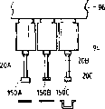
As shown in figure 34, dissimilar electronic component (electronic unit) 150A, 150B and the upper surface of 150C are positioned at the differing heights position.Specifically the upper surface of electronic component 150A is positioned at the highest position.The upper surface of electronic component 150B is positioned at the centre position.The upper surface of electronic component 150C is positioned at extreme lower position.
Controller 23 (see figure 1)s are divided into one group or several groups according to the height and position of electronic component with electronic component 150A, 150B and 150C.Difference between every group of electronic component upper level position is with more relative with 20C than corresponding suction nozzle 20A, 20B little with possible vertical displacement movable axis 94.As electronic component 150C during at second group, electronic component 150A and 150B are at first group.
At first controller 23 (see figure 1)s are set the lower position of suction nozzle 20A and 20B according to the lower position in electronic component 150A in first group and the 150B upper level position.Specifically, set the lower position of suction nozzle 20A and 20B according to the height and position of the upper surface of electronic component 150B.Controller 23 (see figure 1)s control movable axis 94 make and first group of suction nozzle 20A and 20B activity downwards that interior electronic component 150A is relevant with 150B, and the suction nozzle 20C relevant with electronic component 150C remains on uppermost position shown in Figure 35.Before suction nozzle 20B arrived the lower position, suction nozzle 20A and electronic component 150A met.When suction nozzle 20A and electronic component 150A met, suction nozzle 20A began to overcome the power of spring 107 with respect to relevant movable axis 94 activities.Thereby, can absorb the vibrations on the suction nozzle 20A.Then as shown in figure 36, suction nozzle 20A and 20B pick up electronic component 150A and 150B respectively.Controller 23 (see figure 1)s control movable axis 94 makes the suction nozzle 20A and the 20B that have electronic component 150A and 150B move up to upper limit position.
Subsequently, controller 23 (see figure 1)s according to electronic component 150C upper surface the lower position of set positions suction nozzle 20C.The movable axis 94 that the control of controller 23 (see figure 1)s is relevant with suction nozzle 20C makes suction nozzle 20C move downward to lower position shown in Figure 37.Then, as shown in figure 38, suction nozzle 20C picks up electronic component 150C.Controller 23 (see figure 1)s control movable axis 94 makes the suction nozzle 20C that has electronic component 150C move up to upper limit position.By this method, electronic component 150A, 150B and 150C are picked up and are held by suction nozzle 20A, 20B and 20C respectively.
The 3rd embodiment
With the design variation that illustrates, the third embodiment of the present invention is similar to second embodiment except below.
As shown in figure 39, dissimilar electronic component (electronic unit) 150A, 150B and the upper surface of 150C are positioned at the differing heights position.Specifically the upper surface of electronic component 150A is positioned at the highest position.The upper surface of electronic component 150B is positioned at the centre position.The upper surface of electronic component 150C is positioned at extreme lower position.
Controller 23 (see figure 1)s are divided into one group or several groups according to the height and position of electronic component with electronic component 150A, 150B and 150C.More preferably, the difference between every group of electronic component upper level position is with more relative with 20C than corresponding suction nozzle 20A, 20B little with possible vertical displacement movable axis 94.As electronic component 150C during at second group, electronic component 150A and 150B are at first group.
At first controller 23 (see figure 1)s are set the lower position of suction nozzle 20A and 20B according to the lower position in electronic component 150A in first group and the 150B upper level position.Specifically, set the lower position of suction nozzle 20A and 20B according to the height and position of the upper surface of electronic component 150B.Controller 23 (see figure 1)s control movable axis 94 makes and first group of suction nozzle 20A, 20B and 20C activity downwards as shown in figure 40 that interior electronic component 150A, 150B is relevant with 150C.Before suction nozzle 20B arrived the lower position, suction nozzle 20A and electronic component 150A met.When suction nozzle 20A and electronic component 150A met, suction nozzle 20A began to overcome the power of spring 107 with respect to relevant movable axis 94 activities.Though suction nozzle 20C moves downward the lower position, suction nozzle 20C keeps not contacting with electronic component 150C.
Subsequently, controller 23 (see figure 1)s according to electronic component 150C upper surface the lower position of set positions suction nozzle 20C.The movable axis 94 that the control of controller 23 (see figure 1)s is relevant with 20C with suction nozzle 20A, 20B make suction nozzle 20C move downward to lower position shown in Figure 37, and suction nozzle 20A keeps contacting with 150B with electronic component 150A as shown in figure 41 with 20B.In this process, keep with electronic component 150A with when 150B contacts, suction nozzle 20A overcomes the power of spring 107 with respect to 94 activities of relevant movable axis with 20B.Then as shown in figure 42, suction nozzle 20A, 20B and 20C pick up electronic component 150A, 150B and 150.Controller 23 (see figure 1)s control movable axis 94 makes suction nozzle 20A, the 20B and the 20C that have electronic unit 150A, 150B and 150C move up to upper limit position.By this method, suction nozzle 20A, 20B and 20C pick up and hold electronic component 150A, 150B and 150C respectively.