CN109715081B - Robotic surgical devices, systems, and related methods - Google Patents
Robotic surgical devices, systems, and related methods Download PDFInfo
- Publication number
- CN109715081B CN109715081B CN201780044266.8A CN201780044266A CN109715081B CN 109715081 B CN109715081 B CN 109715081B CN 201780044266 A CN201780044266 A CN 201780044266A CN 109715081 B CN109715081 B CN 109715081B
- Authority
- CN
- China
- Prior art keywords
- arm
- robotic
- gear pair
- camera
- joint
- Prior art date
- Legal status (The legal status is an assumption and is not a legal conclusion. Google has not performed a legal analysis and makes no representation as to the accuracy of the status listed.)
- Active
Links
Images


Classifications
-
- A—HUMAN NECESSITIES
- A61—MEDICAL OR VETERINARY SCIENCE; HYGIENE
- A61B—DIAGNOSIS; SURGERY; IDENTIFICATION
- A61B34/00—Computer-aided surgery; Manipulators or robots specially adapted for use in surgery
- A61B34/30—Surgical robots
-
- A—HUMAN NECESSITIES
- A61—MEDICAL OR VETERINARY SCIENCE; HYGIENE
- A61B—DIAGNOSIS; SURGERY; IDENTIFICATION
- A61B1/00—Instruments for performing medical examinations of the interior of cavities or tubes of the body by visual or photographical inspection, e.g. endoscopes; Illuminating arrangements therefor
- A61B1/00112—Connection or coupling means
- A61B1/00121—Connectors, fasteners and adapters, e.g. on the endoscope handle
- A61B1/00128—Connectors, fasteners and adapters, e.g. on the endoscope handle mechanical, e.g. for tubes or pipes
-
- A—HUMAN NECESSITIES
- A61—MEDICAL OR VETERINARY SCIENCE; HYGIENE
- A61B—DIAGNOSIS; SURGERY; IDENTIFICATION
- A61B1/00—Instruments for performing medical examinations of the interior of cavities or tubes of the body by visual or photographical inspection, e.g. endoscopes; Illuminating arrangements therefor
- A61B1/00147—Holding or positioning arrangements
- A61B1/0016—Holding or positioning arrangements using motor drive units
-
- A—HUMAN NECESSITIES
- A61—MEDICAL OR VETERINARY SCIENCE; HYGIENE
- A61B—DIAGNOSIS; SURGERY; IDENTIFICATION
- A61B1/00—Instruments for performing medical examinations of the interior of cavities or tubes of the body by visual or photographical inspection, e.g. endoscopes; Illuminating arrangements therefor
- A61B1/005—Flexible endoscopes
- A61B1/0051—Flexible endoscopes with controlled bending of insertion part
- A61B1/0052—Constructional details of control elements, e.g. handles
-
- A—HUMAN NECESSITIES
- A61—MEDICAL OR VETERINARY SCIENCE; HYGIENE
- A61B—DIAGNOSIS; SURGERY; IDENTIFICATION
- A61B1/00—Instruments for performing medical examinations of the interior of cavities or tubes of the body by visual or photographical inspection, e.g. endoscopes; Illuminating arrangements therefor
- A61B1/005—Flexible endoscopes
- A61B1/008—Articulations
-
- A—HUMAN NECESSITIES
- A61—MEDICAL OR VETERINARY SCIENCE; HYGIENE
- A61B—DIAGNOSIS; SURGERY; IDENTIFICATION
- A61B1/00—Instruments for performing medical examinations of the interior of cavities or tubes of the body by visual or photographical inspection, e.g. endoscopes; Illuminating arrangements therefor
- A61B1/04—Instruments for performing medical examinations of the interior of cavities or tubes of the body by visual or photographical inspection, e.g. endoscopes; Illuminating arrangements therefor combined with photographic or television appliances
- A61B1/045—Control thereof
-
- A—HUMAN NECESSITIES
- A61—MEDICAL OR VETERINARY SCIENCE; HYGIENE
- A61B—DIAGNOSIS; SURGERY; IDENTIFICATION
- A61B1/00—Instruments for performing medical examinations of the interior of cavities or tubes of the body by visual or photographical inspection, e.g. endoscopes; Illuminating arrangements therefor
- A61B1/04—Instruments for performing medical examinations of the interior of cavities or tubes of the body by visual or photographical inspection, e.g. endoscopes; Illuminating arrangements therefor combined with photographic or television appliances
- A61B1/05—Instruments for performing medical examinations of the interior of cavities or tubes of the body by visual or photographical inspection, e.g. endoscopes; Illuminating arrangements therefor combined with photographic or television appliances characterised by the image sensor, e.g. camera, being in the distal end portion
- A61B1/051—Details of CCD assembly
-
- A—HUMAN NECESSITIES
- A61—MEDICAL OR VETERINARY SCIENCE; HYGIENE
- A61B—DIAGNOSIS; SURGERY; IDENTIFICATION
- A61B1/00—Instruments for performing medical examinations of the interior of cavities or tubes of the body by visual or photographical inspection, e.g. endoscopes; Illuminating arrangements therefor
- A61B1/06—Instruments for performing medical examinations of the interior of cavities or tubes of the body by visual or photographical inspection, e.g. endoscopes; Illuminating arrangements therefor with illuminating arrangements
-
- A—HUMAN NECESSITIES
- A61—MEDICAL OR VETERINARY SCIENCE; HYGIENE
- A61B—DIAGNOSIS; SURGERY; IDENTIFICATION
- A61B17/00—Surgical instruments, devices or methods
- A61B17/02—Surgical instruments, devices or methods for holding wounds open, e.g. retractors; Tractors
-
- A—HUMAN NECESSITIES
- A61—MEDICAL OR VETERINARY SCIENCE; HYGIENE
- A61B—DIAGNOSIS; SURGERY; IDENTIFICATION
- A61B18/00—Surgical instruments, devices or methods for transferring non-mechanical forms of energy to or from the body
- A61B18/04—Surgical instruments, devices or methods for transferring non-mechanical forms of energy to or from the body by heating
- A61B18/12—Surgical instruments, devices or methods for transferring non-mechanical forms of energy to or from the body by heating by passing a current through the tissue to be heated, e.g. high-frequency current
- A61B18/1206—Generators therefor
-
- A—HUMAN NECESSITIES
- A61—MEDICAL OR VETERINARY SCIENCE; HYGIENE
- A61B—DIAGNOSIS; SURGERY; IDENTIFICATION
- A61B18/00—Surgical instruments, devices or methods for transferring non-mechanical forms of energy to or from the body
- A61B18/04—Surgical instruments, devices or methods for transferring non-mechanical forms of energy to or from the body by heating
- A61B18/12—Surgical instruments, devices or methods for transferring non-mechanical forms of energy to or from the body by heating by passing a current through the tissue to be heated, e.g. high-frequency current
- A61B18/14—Probes or electrodes therefor
- A61B18/1482—Probes or electrodes therefor having a long rigid shaft for accessing the inner body transcutaneously in minimal invasive surgery, e.g. laparoscopy
-
- A—HUMAN NECESSITIES
- A61—MEDICAL OR VETERINARY SCIENCE; HYGIENE
- A61B—DIAGNOSIS; SURGERY; IDENTIFICATION
- A61B34/00—Computer-aided surgery; Manipulators or robots specially adapted for use in surgery
- A61B34/30—Surgical robots
- A61B34/32—Surgical robots operating autonomously
-
- A—HUMAN NECESSITIES
- A61—MEDICAL OR VETERINARY SCIENCE; HYGIENE
- A61B—DIAGNOSIS; SURGERY; IDENTIFICATION
- A61B34/00—Computer-aided surgery; Manipulators or robots specially adapted for use in surgery
- A61B34/70—Manipulators specially adapted for use in surgery
-
- A—HUMAN NECESSITIES
- A61—MEDICAL OR VETERINARY SCIENCE; HYGIENE
- A61B—DIAGNOSIS; SURGERY; IDENTIFICATION
- A61B34/00—Computer-aided surgery; Manipulators or robots specially adapted for use in surgery
- A61B34/70—Manipulators specially adapted for use in surgery
- A61B34/76—Manipulators having means for providing feel, e.g. force or tactile feedback
-
- A—HUMAN NECESSITIES
- A61—MEDICAL OR VETERINARY SCIENCE; HYGIENE
- A61B—DIAGNOSIS; SURGERY; IDENTIFICATION
- A61B34/00—Computer-aided surgery; Manipulators or robots specially adapted for use in surgery
- A61B34/70—Manipulators specially adapted for use in surgery
- A61B34/77—Manipulators with motion or force scaling
-
- A—HUMAN NECESSITIES
- A61—MEDICAL OR VETERINARY SCIENCE; HYGIENE
- A61B—DIAGNOSIS; SURGERY; IDENTIFICATION
- A61B90/00—Instruments, implements or accessories specially adapted for surgery or diagnosis and not covered by any of the groups A61B1/00 - A61B50/00, e.g. for luxation treatment or for protecting wound edges
- A61B90/36—Image-producing devices or illumination devices not otherwise provided for
- A61B90/361—Image-producing devices, e.g. surgical cameras
-
- A—HUMAN NECESSITIES
- A61—MEDICAL OR VETERINARY SCIENCE; HYGIENE
- A61B—DIAGNOSIS; SURGERY; IDENTIFICATION
- A61B90/00—Instruments, implements or accessories specially adapted for surgery or diagnosis and not covered by any of the groups A61B1/00 - A61B50/00, e.g. for luxation treatment or for protecting wound edges
- A61B90/36—Image-producing devices or illumination devices not otherwise provided for
- A61B90/37—Surgical systems with images on a monitor during operation
-
- A—HUMAN NECESSITIES
- A61—MEDICAL OR VETERINARY SCIENCE; HYGIENE
- A61B—DIAGNOSIS; SURGERY; IDENTIFICATION
- A61B1/00—Instruments for performing medical examinations of the interior of cavities or tubes of the body by visual or photographical inspection, e.g. endoscopes; Illuminating arrangements therefor
- A61B1/313—Instruments for performing medical examinations of the interior of cavities or tubes of the body by visual or photographical inspection, e.g. endoscopes; Illuminating arrangements therefor for introducing through surgical openings, e.g. laparoscopes
- A61B1/3132—Instruments for performing medical examinations of the interior of cavities or tubes of the body by visual or photographical inspection, e.g. endoscopes; Illuminating arrangements therefor for introducing through surgical openings, e.g. laparoscopes for laparoscopy
-
- A—HUMAN NECESSITIES
- A61—MEDICAL OR VETERINARY SCIENCE; HYGIENE
- A61B—DIAGNOSIS; SURGERY; IDENTIFICATION
- A61B17/00—Surgical instruments, devices or methods
- A61B17/34—Trocars; Puncturing needles
- A61B17/3417—Details of tips or shafts, e.g. grooves, expandable, bendable; Multiple coaxial sliding cannulas, e.g. for dilating
- A61B17/3421—Cannulas
- A61B17/3423—Access ports, e.g. toroid shape introducers for instruments or hands
-
- A—HUMAN NECESSITIES
- A61—MEDICAL OR VETERINARY SCIENCE; HYGIENE
- A61B—DIAGNOSIS; SURGERY; IDENTIFICATION
- A61B17/00—Surgical instruments, devices or methods
- A61B2017/00017—Electrical control of surgical instruments
- A61B2017/00022—Sensing or detecting at the treatment site
- A61B2017/00084—Temperature
- A61B2017/00101—Temperature using an array of thermosensors
-
- A—HUMAN NECESSITIES
- A61—MEDICAL OR VETERINARY SCIENCE; HYGIENE
- A61B—DIAGNOSIS; SURGERY; IDENTIFICATION
- A61B17/00—Surgical instruments, devices or methods
- A61B2017/00017—Electrical control of surgical instruments
- A61B2017/00199—Electrical control of surgical instruments with a console, e.g. a control panel with a display
-
- A—HUMAN NECESSITIES
- A61—MEDICAL OR VETERINARY SCIENCE; HYGIENE
- A61B—DIAGNOSIS; SURGERY; IDENTIFICATION
- A61B17/00—Surgical instruments, devices or methods
- A61B17/00234—Surgical instruments, devices or methods for minimally invasive surgery
- A61B2017/00292—Surgical instruments, devices or methods for minimally invasive surgery mounted on or guided by flexible, e.g. catheter-like, means
- A61B2017/003—Steerable
- A61B2017/00305—Constructional details of the flexible means
- A61B2017/00309—Cut-outs or slits
-
- A—HUMAN NECESSITIES
- A61—MEDICAL OR VETERINARY SCIENCE; HYGIENE
- A61B—DIAGNOSIS; SURGERY; IDENTIFICATION
- A61B17/00—Surgical instruments, devices or methods
- A61B17/00234—Surgical instruments, devices or methods for minimally invasive surgery
- A61B2017/00292—Surgical instruments, devices or methods for minimally invasive surgery mounted on or guided by flexible, e.g. catheter-like, means
- A61B2017/003—Steerable
- A61B2017/00305—Constructional details of the flexible means
- A61B2017/00314—Separate linked members
-
- A—HUMAN NECESSITIES
- A61—MEDICAL OR VETERINARY SCIENCE; HYGIENE
- A61B—DIAGNOSIS; SURGERY; IDENTIFICATION
- A61B17/00—Surgical instruments, devices or methods
- A61B17/00234—Surgical instruments, devices or methods for minimally invasive surgery
- A61B2017/00292—Surgical instruments, devices or methods for minimally invasive surgery mounted on or guided by flexible, e.g. catheter-like, means
- A61B2017/003—Steerable
- A61B2017/00318—Steering mechanisms
- A61B2017/00323—Cables or rods
- A61B2017/00327—Cables or rods with actuating members moving in opposite directions
-
- A—HUMAN NECESSITIES
- A61—MEDICAL OR VETERINARY SCIENCE; HYGIENE
- A61B—DIAGNOSIS; SURGERY; IDENTIFICATION
- A61B17/00—Surgical instruments, devices or methods
- A61B2017/0046—Surgical instruments, devices or methods with a releasable handle; with handle and operating part separable
- A61B2017/00473—Distal part, e.g. tip or head
-
- A—HUMAN NECESSITIES
- A61—MEDICAL OR VETERINARY SCIENCE; HYGIENE
- A61B—DIAGNOSIS; SURGERY; IDENTIFICATION
- A61B17/00—Surgical instruments, devices or methods
- A61B17/28—Surgical forceps
- A61B17/29—Forceps for use in minimally invasive surgery
- A61B2017/2901—Details of shaft
- A61B2017/2906—Multiple forceps
-
- A—HUMAN NECESSITIES
- A61—MEDICAL OR VETERINARY SCIENCE; HYGIENE
- A61B—DIAGNOSIS; SURGERY; IDENTIFICATION
- A61B17/00—Surgical instruments, devices or methods
- A61B17/34—Trocars; Puncturing needles
- A61B2017/347—Locking means, e.g. for locking instrument in cannula
-
- A—HUMAN NECESSITIES
- A61—MEDICAL OR VETERINARY SCIENCE; HYGIENE
- A61B—DIAGNOSIS; SURGERY; IDENTIFICATION
- A61B18/00—Surgical instruments, devices or methods for transferring non-mechanical forms of energy to or from the body
- A61B2018/00053—Mechanical features of the instrument of device
- A61B2018/00172—Connectors and adapters therefor
- A61B2018/00178—Electrical connectors
-
- A—HUMAN NECESSITIES
- A61—MEDICAL OR VETERINARY SCIENCE; HYGIENE
- A61B—DIAGNOSIS; SURGERY; IDENTIFICATION
- A61B18/00—Surgical instruments, devices or methods for transferring non-mechanical forms of energy to or from the body
- A61B2018/00571—Surgical instruments, devices or methods for transferring non-mechanical forms of energy to or from the body for achieving a particular surgical effect
- A61B2018/00589—Coagulation
-
- A—HUMAN NECESSITIES
- A61—MEDICAL OR VETERINARY SCIENCE; HYGIENE
- A61B—DIAGNOSIS; SURGERY; IDENTIFICATION
- A61B18/00—Surgical instruments, devices or methods for transferring non-mechanical forms of energy to or from the body
- A61B2018/00571—Surgical instruments, devices or methods for transferring non-mechanical forms of energy to or from the body for achieving a particular surgical effect
- A61B2018/00595—Cauterization
-
- A—HUMAN NECESSITIES
- A61—MEDICAL OR VETERINARY SCIENCE; HYGIENE
- A61B—DIAGNOSIS; SURGERY; IDENTIFICATION
- A61B18/00—Surgical instruments, devices or methods for transferring non-mechanical forms of energy to or from the body
- A61B2018/00571—Surgical instruments, devices or methods for transferring non-mechanical forms of energy to or from the body for achieving a particular surgical effect
- A61B2018/00601—Cutting
-
- A—HUMAN NECESSITIES
- A61—MEDICAL OR VETERINARY SCIENCE; HYGIENE
- A61B—DIAGNOSIS; SURGERY; IDENTIFICATION
- A61B18/00—Surgical instruments, devices or methods for transferring non-mechanical forms of energy to or from the body
- A61B18/04—Surgical instruments, devices or methods for transferring non-mechanical forms of energy to or from the body by heating
- A61B18/12—Surgical instruments, devices or methods for transferring non-mechanical forms of energy to or from the body by heating by passing a current through the tissue to be heated, e.g. high-frequency current
- A61B18/1206—Generators therefor
- A61B2018/1246—Generators therefor characterised by the output polarity
- A61B2018/1253—Generators therefor characterised by the output polarity monopolar
-
- A—HUMAN NECESSITIES
- A61—MEDICAL OR VETERINARY SCIENCE; HYGIENE
- A61B—DIAGNOSIS; SURGERY; IDENTIFICATION
- A61B34/00—Computer-aided surgery; Manipulators or robots specially adapted for use in surgery
- A61B34/30—Surgical robots
- A61B2034/301—Surgical robots for introducing or steering flexible instruments inserted into the body, e.g. catheters or endoscopes
-
- A—HUMAN NECESSITIES
- A61—MEDICAL OR VETERINARY SCIENCE; HYGIENE
- A61B—DIAGNOSIS; SURGERY; IDENTIFICATION
- A61B34/00—Computer-aided surgery; Manipulators or robots specially adapted for use in surgery
- A61B34/30—Surgical robots
- A61B2034/302—Surgical robots specifically adapted for manipulations within body cavities, e.g. within abdominal or thoracic cavities
-
- A—HUMAN NECESSITIES
- A61—MEDICAL OR VETERINARY SCIENCE; HYGIENE
- A61B—DIAGNOSIS; SURGERY; IDENTIFICATION
- A61B34/00—Computer-aided surgery; Manipulators or robots specially adapted for use in surgery
- A61B34/30—Surgical robots
- A61B2034/305—Details of wrist mechanisms at distal ends of robotic arms
-
- A—HUMAN NECESSITIES
- A61—MEDICAL OR VETERINARY SCIENCE; HYGIENE
- A61B—DIAGNOSIS; SURGERY; IDENTIFICATION
- A61B34/00—Computer-aided surgery; Manipulators or robots specially adapted for use in surgery
- A61B34/70—Manipulators specially adapted for use in surgery
- A61B34/74—Manipulators with manual electric input means
- A61B2034/742—Joysticks
-
- A—HUMAN NECESSITIES
- A61—MEDICAL OR VETERINARY SCIENCE; HYGIENE
- A61B—DIAGNOSIS; SURGERY; IDENTIFICATION
- A61B90/00—Instruments, implements or accessories specially adapted for surgery or diagnosis and not covered by any of the groups A61B1/00 - A61B50/00, e.g. for luxation treatment or for protecting wound edges
- A61B90/50—Supports for surgical instruments, e.g. articulated arms
- A61B2090/506—Supports for surgical instruments, e.g. articulated arms using a parallelogram linkage, e.g. panthograph
-
- A—HUMAN NECESSITIES
- A61—MEDICAL OR VETERINARY SCIENCE; HYGIENE
- A61B—DIAGNOSIS; SURGERY; IDENTIFICATION
- A61B90/00—Instruments, implements or accessories specially adapted for surgery or diagnosis and not covered by any of the groups A61B1/00 - A61B50/00, e.g. for luxation treatment or for protecting wound edges
- A61B90/50—Supports for surgical instruments, e.g. articulated arms
- A61B90/57—Accessory clamps
- A61B2090/571—Accessory clamps for clamping a support arm to a bed or other supports
-
- A—HUMAN NECESSITIES
- A61—MEDICAL OR VETERINARY SCIENCE; HYGIENE
- A61B—DIAGNOSIS; SURGERY; IDENTIFICATION
- A61B34/00—Computer-aided surgery; Manipulators or robots specially adapted for use in surgery
- A61B34/70—Manipulators specially adapted for use in surgery
- A61B34/74—Manipulators with manual electric input means
-
- A—HUMAN NECESSITIES
- A61—MEDICAL OR VETERINARY SCIENCE; HYGIENE
- A61B—DIAGNOSIS; SURGERY; IDENTIFICATION
- A61B90/00—Instruments, implements or accessories specially adapted for surgery or diagnosis and not covered by any of the groups A61B1/00 - A61B50/00, e.g. for luxation treatment or for protecting wound edges
- A61B90/10—Instruments, implements or accessories specially adapted for surgery or diagnosis and not covered by any of the groups A61B1/00 - A61B50/00, e.g. for luxation treatment or for protecting wound edges for stereotaxic surgery, e.g. frame-based stereotaxis
- A61B90/11—Instruments, implements or accessories specially adapted for surgery or diagnosis and not covered by any of the groups A61B1/00 - A61B50/00, e.g. for luxation treatment or for protecting wound edges for stereotaxic surgery, e.g. frame-based stereotaxis with guides for needles or instruments, e.g. arcuate slides or ball joints
Landscapes
- Health & Medical Sciences (AREA)
- Life Sciences & Earth Sciences (AREA)
- Surgery (AREA)
- Engineering & Computer Science (AREA)
- Nuclear Medicine, Radiotherapy & Molecular Imaging (AREA)
- Molecular Biology (AREA)
- Veterinary Medicine (AREA)
- Public Health (AREA)
- General Health & Medical Sciences (AREA)
- Biomedical Technology (AREA)
- Heart & Thoracic Surgery (AREA)
- Medical Informatics (AREA)
- Animal Behavior & Ethology (AREA)
- Pathology (AREA)
- Physics & Mathematics (AREA)
- Radiology & Medical Imaging (AREA)
- Biophysics (AREA)
- Optics & Photonics (AREA)
- Robotics (AREA)
- Oral & Maxillofacial Surgery (AREA)
- Plasma & Fusion (AREA)
- Otolaryngology (AREA)
- Gynecology & Obstetrics (AREA)
- Mechanical Engineering (AREA)
- Rehabilitation Therapy (AREA)
- Manipulator (AREA)
Abstract
Various inventions relate to robotic surgical devices, consoles for operating such surgical devices, operating rooms in which various devices may be used, insertion systems for inserting and using surgical devices, and related methods.
Description
Cross Reference to Related Applications
This application claims priority from U.S. provisional application No.62/338,375, filed 2016, 5, 18, and entitled "rolling scientific Devices, Systems and Related Methods," which is incorporated herein by reference in its entirety as per 35u.s.c. § 119 (e).
Technical Field
Embodiments disclosed herein relate to various medical devices and related components, including robotic and/or in-vivo medical devices and related components. Certain embodiments include various robotic medical devices, including robotic devices disposed within a body cavity and positioned using a support member disposed through an aperture or opening in the body cavity. Further embodiments relate to methods and apparatus for operating the above apparatus.
Background
Invasive surgery is essential to address a variety of medical conditions. Minimally invasive surgery, such as laparoscopy, is preferred when possible.
However, known minimally invasive techniques (e.g., laparoscopy) are limited in scope and complexity, in part because: 1) the limitation of movement caused by the use of a rigid tool inserted through the access port, and 2) limited visual feedback. Such as da Known robotic systems of Surgical systems (available from Intuitive Surgical corporation in Sunnyvale, CA) are also limited by access ports, and have the additional disadvantage of being very large, very expensive, not available in most hospitals, and having limited sensing and movement capabilities.
There is a need in the art for improved surgical methods, systems, and devices.
Disclosure of Invention
Discussed herein are various robotic surgical systems, including certain systems having a camera lumen configured to receive various camera systems. Further embodiments relate to surgical insertion devices configured for inserting various surgical devices into a cavity of a patient while maintaining insufflation of the cavity.
In one example, a robotic surgical system, comprising: a robotic surgical device and a camera component, the robotic surgical device comprising: a device body comprising a front side and a back side and a distal end and a proximal end; a first shoulder joint and a second shoulder joint operably coupled to the distal end of the device body; a first robotic arm operably coupled to the first shoulder joint; and a second robotic arm operably coupled to the second shoulder joint, the camera component comprising a flexible section and a distal imager, wherein the first and second robotic arms are constructed and arranged to be positioned on a front or back side of the body.
Implementations may include one or more of the following features. A robotic surgical system in which the surgical device includes at least one actuator. A robotic surgical system in which the first and second robotic arms include at least one motor disposed within each of the first and second robotic arms. The robotic surgical system also includes a support device configured to remotely center the robotic surgical device. The robotic surgical system also includes a surgical console. A robotic surgical system in which a camera is disposed through a lumen defined in a robotic surgical device. A robotic surgical system in which the camera is configured as an adjustable height camera. A robotic surgical system in which the camera is constructed and arranged to be capable of pitch (pitch) and yaw (yaw). Wherein the distal camera tip is configured to be directed to a robotic surgical system defining a workspace. A robotic surgical system in which the camera includes a light. Wherein the robotic surgical device further comprises a robotic surgical system of the first and second end effectors. Wherein the first robotic arm further comprises an upper arm and a forearm. A robotic surgical system wherein the first robotic arm further comprises: a first arm upper arm; a first elbow joint; and a first arm lower arm, wherein the first arm upper arm is configured to be capable of roll, pitch, and yaw relative to a first shoulder joint and the first arm lower arm is configured to be capable of yaw relative to the first arm upper arm through a first arm elbow joint. Wherein the first robotic arm further comprises at least one first arm actuator disposed within the first robotic arm. A robotic surgical system in which the second robotic arm further comprises: a second arm upper arm; a second elbow joint; and a second arm lower arm, wherein the second arm upper arm is configured to be able to roll, pitch and yaw relative to the second shoulder joint and the second arm lower arm is configured to be able to yaw relative to the second arm upper arm through the second arm elbow joint. Wherein the second robotic arm further comprises at least one second arm actuator disposed within the second robotic arm. A robotic surgical system in which the first and second arms include at least one motor disposed in each arm. The robotic surgical system also includes at least one PCB disposed within and in operable communication with at least one of the first or second robotic arms, wherein the PCB is configured to perform yaw and pitch functions.
One example includes a robotic surgical system comprising: a robotic surgical device and a camera component, the robotic surgical device comprising: a device body comprising a distal end, a proximal end, a front side, and a back side; first and second shoulder joints operably coupled to a distal end of the device body; a first robotic arm operably coupled to the first shoulder joint; and a second robotic arm operably coupled to a second shoulder joint, the camera component comprising: a shaft; an imager; and a flexible section operably coupling the imager to the shaft, wherein the first and second robotic arms are constructed and arranged to be positioned on a front or back side of the body. Implementations may include one or more of the following features. Wherein the first robotic arm further comprises an upper arm and a forearm. A robotic surgical system wherein the first robotic arm further comprises: a first arm upper arm; a first elbow joint; and a first arm lower arm, wherein the first arm upper arm is configured to be able to roll, pitch and yaw relative to the first shoulder joint and the first arm lower arm is configured to be able to yaw relative to the first arm upper arm through the first arm elbow joint. Wherein the first robotic arm further comprises at least one first arm actuator disposed within the first robotic arm. A robotic surgical system in which the second robotic arm further comprises: a second arm upper arm; a second elbow joint; and a second arm lower arm, wherein the second arm upper arm is configured to be able to roll, pitch and yaw relative to the second shoulder joint and the second arm lower arm is configured to be able to yaw relative to the second arm upper arm through the second arm elbow joint. Wherein the second robotic arm further comprises at least one second arm actuator disposed within the second robotic arm. A robotic surgical system in which the first and second arms include at least one motor disposed in each arm. The robotic surgical system also includes at least one PCB disposed within and in operable communication with at least one of the first or second robotic arms, wherein the PCB is configured to perform yaw and pitch functions. Embodiments of the described technology may include hardware, methods or processes, or computer software on a computer-accessible medium.
Another example includes a robotic surgical system comprising: a robotic surgical device and a camera component, the robotic surgical device comprising: a device body; first and second shoulder joints operably coupled to a distal end of the device body; a first robotic arm operably coupled to the first shoulder joint; and a second robotic arm operably coupled to a second shoulder joint, the device body comprising: a distal end; a proximal end; and a camera lumen defined within the device body, the camera lumen comprising: a proximal lumen opening in the proximal end of the device body; a socket portion defined distal to the proximal lumen opening, the socket portion including a first diameter and a first coupling member; an extension defined distally of the socket portion, the extension having a second smaller diameter; and a distal lumen opening in the distal end of the device body, the distal lumen opening defined at the distal end of the extension, the camera component including an elongated tube operably coupled to the handle, wherein the elongated tube is configured and dimensioned to be positionable through the extension, the elongated tube including: a shaft; an imager; and a flexible section operably coupling the optical section to the rigid section, wherein the elongate tube has a length such that at least the optical section is configured to extend distally from the distal lumen opening when the camera component is positioned through the camera lumen.
Implementations may include one or more of the following features. A robotic surgical system in which the first and second arms include at least one motor disposed in each arm. The robotic surgical system also includes at least one PCB disposed within and in operable communication with at least one of the first or second robotic arms, wherein the PCB is configured to perform yaw and pitch functions.
While multiple embodiments are disclosed, other embodiments of the present invention will become apparent to those skilled in the art from the following detailed description, which shows and describes illustrative embodiments of the invention. As will be realized, the invention is capable of modifications in various obvious aspects, all without departing from the spirit and scope of the present invention. Accordingly, the drawings and detailed description are to be regarded as illustrative in nature and not as restrictive.
Drawings
Fig. 1A is a front view of a surgical device according to one embodiment.
FIG. 1B is a front view of the device of FIG. 1A inserted into a body cavity.
FIG. 2 is a front view of a surgical device according to one embodiment.
Fig. 3 is a three-quarter perspective view of the embodiment of fig. 2 without the camera.
Fig. 4 is a three-quarter perspective view of the camera of the embodiment of fig. 2 without the robot.
FIG. 5A is a close-up perspective view of a surgical device according to one embodiment.
Fig. 5B is a front view of the embodiment of fig. 5A, with the arm and camera in an "inserted" position.
FIG. 6A is a perspective view of a surgical device showing various working spaces of the arm, according to one embodiment.
Figure 6B is yet another perspective view of the surgical device of figure 6A showing the working space of one arm.
Fig. 7A is a side view of a robot according to one embodiment, illustrating the range of motion of the arm and the associated workspace according to one embodiment.
Fig. 7B is a top view of the embodiment of fig. 7A, illustrating the range of motion of the arm and the associated workspace.
Fig. 7C is a perspective view of the embodiment of fig. 7A, illustrating the range of motion of the arm and the associated workspace.
Figure 8A is a rear perspective view of one embodiment of a surgical device showing the positioning of the arms to the front and back of the device, according to one embodiment.
Fig. 8B is a three-quarter rear view of the device of fig. 8A, showing several possible arm positions.
Fig. 8C is a lower perspective elevation view of the device showing the arm position of fig. 8B.
FIG. 9 is a perspective view of a surgical device showing the camera and arm oriented in a central "down" working position according to one embodiment.
Fig. 10 is a front view of the device of fig. 9, showing the arms in a central "up" position.
FIG. 11 is a perspective view of a surgical device showing the arms in a "down" position according to one embodiment.
FIG. 12A is a top view of a surgical device according to one embodiment.
Fig. 12B is a top view of a surgical device according to another embodiment.
FIG. 12C is an elevation view of a surgical device according to one embodiment.
Fig. 12D is an elevation view of a surgical device according to another embodiment.
FIG. 12E is a side view of a surgical device according to one embodiment.
Fig. 12F is a side view of a surgical device according to another embodiment.
FIG. 13A is a perspective view of a surgical device showing movement of a first joint, according to one embodiment.
FIG. 13B is a perspective view of a surgical device showing movement of a second joint, according to one embodiment.
FIG. 13C is a perspective view of a surgical device showing movement of a third joint, according to one embodiment.
FIG. 13D is a perspective view of a surgical device showing movement of a fourth joint, according to one embodiment.
Fig. 14 is a perspective view of a robotic surgical device showing internal components, according to one embodiment.
FIG. 15 is a front view of an internal component showing a body and a shoulder according to one embodiment.
FIG. 16 is a perspective view illustrating internal components of a body according to one embodiment.
FIG. 17 is a perspective view of an internal component showing a shoulder according to one embodiment.
FIG. 18 is a side view of an internal component showing a shoulder according to one embodiment.
FIG. 19 is an inverted perspective view of an internal component showing a body and a shoulder according to one embodiment.
FIG. 20 is a perspective view illustrating internal components of an upper arm, according to one embodiment.
FIG. 21 is a perspective view illustrating further internal components of the upper arm, according to one embodiment.
FIG. 22 is a front view illustrating further internal components of the upper arm, according to one embodiment.
FIG. 23 is a perspective view illustrating further internal components of the upper arm, according to one embodiment.
Figure 24 is a perspective view illustrating internal components of a lower arm according to one embodiment.
FIG. 25 is a perspective view illustrating further internal components of the upper arm, according to one embodiment.
FIG. 26 is a perspective view illustrating further internal components of the upper arm, according to one embodiment.
FIG. 27 is a perspective view illustrating still further internal components of the upper arm, according to one embodiment.
Fig. 28A is a front perspective view of a surgical device having an articulating camera, according to one embodiment.
Fig. 28B is a close-up perspective view of the camera of fig. 28A, illustrating various possible motions.
Figure 28C is a front view of a robotic device and camera with adjustable depth according to one embodiment.
Fig. 28D is a close-up view of the device lumen and camera shaft showing the adjustable depth mechanism, showing the camera in an "up" position, according to one embodiment.
Fig. 28E is a front view of the robot and camera according to the embodiment of fig. 28C and 28D.
Figure 28F is a front view of a robotic device and camera with adjustable depth according to one embodiment.
Fig. 28G is a close-up view of the device lumen and camera shaft showing the adjustable depth mechanism, showing the camera in a "down" position, according to one embodiment.
Fig. 28H is a front view of the robot and camera according to the embodiment of fig. 28F and 28G.
Fig. 28I is a cross-sectional view of a body lumen according to one embodiment.
Fig. 29A-29B depict a surgical device workspace and field of view, according to an exemplary embodiment.
Fig. 30A-30F depict a surgical device and a zero degree camera through a range of possible positions, according to one embodiment.
Fig. 31A-31F depict a surgical device and a thirty degree camera through a range of possible positions according to another embodiment.
Fig. 32A-32F depict a surgical device and a sixty degree camera through a range of possible positions, according to one embodiment.
Fig. 33A-33C depict a surgical device and camera through a range of possible positions having an "S-shaped range" configuration, according to one embodiment.
Fig. 34A is an embodiment of an articulating camera tip portion.
Fig. 34B is another embodiment of an articulating camera tip portion.
Fig. 34C is yet another embodiment of an articulating camera tip portion.
Fig. 35A-35C are side views of a surgical device and a camera showing movement of the camera between various positions according to several embodiments.
Fig. 36A-36C are side views of a surgical device end effector according to one embodiment.
Figure 37 is an elevation view of a surgical device on a support structure according to one embodiment.
FIG. 38 is a perspective view of a surgical device on a support structure according to one embodiment.
FIG. 39 is a cross-sectional view of a surgical device at an insertion point, according to one embodiment.
Figure 40A is a perspective view of a surgical device on a support structure according to one embodiment.
Figure 40B is a side view of a surgical device on a support structure according to one embodiment.
Figure 41A is a perspective view of a surgical device on a support structure according to one embodiment.
Figure 41B is a further perspective view of the surgical device on a support structure according to the embodiment of figure 41A.
Figure 42A is a perspective view of a surgical device on another support structure according to one embodiment.
Fig. 42B is a further perspective view of the surgical device on a support structure according to the embodiment of fig. 42A.
Fig. 42C is yet another perspective view of the surgical device on a support structure according to the embodiment of fig. 42A.
FIG. 43 is a side view of a surgical device on yet another support structure according to one embodiment.
FIG. 44 is yet another perspective view of a surgical device on a support structure according to another embodiment.
FIG. 45 is a perspective view of a surgical device on a support robot according to another embodiment.
FIG. 46 is a perspective view of a surgical device on a support robot according to yet another embodiment.
Figure 47 is a perspective view of a surgical device on a spherical joint support structure according to another embodiment.
Figures 48A-48D-2 illustrate side and top views of a support structure of a positioning surgical device, according to one embodiment.
Figure 49 is a perspective view of a support structure positioning a surgical device, according to one embodiment.
Figure 50A is a perspective view of another support structure positioning a surgical device, according to one embodiment.
Figure 50B is a side view of another support structure positioning a surgical device according to one embodiment.
Figure 50C is a side view of another support structure positioning a surgical device according to one embodiment.
Figure 50D is a side view of another support structure positioning a surgical device according to one embodiment.
FIG. 51 is a perspective view of another support structure positioning a surgical device, according to one embodiment.
Figure 52A is a side view of another support structure positioning a surgical device according to one embodiment.
Figure 52B is a perspective view of another support structure positioning a surgical device, according to one embodiment.
Figure 52C is a perspective view of another support structure positioning a surgical device, according to one embodiment.
Figure 52D is a perspective view of another support structure positioning a surgical device, according to one embodiment.
Figure 52E is a perspective view of another support structure positioning a surgical device, according to one embodiment.
Figure 52F is a perspective view of another support structure positioning a surgical device, according to one embodiment.
FIG. 53 is a perspective view of a surgical console according to one embodiment.
FIG. 54 is a schematic view of a surgical system according to one embodiment.
FIG. 55 is another schematic view of a surgical system according to one embodiment.
Detailed Description
Various systems and devices disclosed herein relate to devices for use in medical procedures and systems. More particularly, various embodiments relate to various medical devices, including robotic devices and related methods and systems.
It should be understood that the various embodiments of the robotic devices and associated methods and systems disclosed herein may be incorporated into or used with any other known medical devices, systems and methods.
It should be understood that the various embodiments of the robotic devices and associated methods and systems disclosed herein may be incorporated into or used with any other known medical devices, systems and methods. For example, the various embodiments disclosed herein may be incorporated into or used with any of the medical devices and systems disclosed in the following co-pending U.S. applications: 11/766, 683 (21.6.2007 and entitled "magnetic compatible polymeric Devices and Related Methods"), 11/766, 720 (21.6.2007 and entitled "magnetic compatible polymeric Devices and Related Methods"), 11/966, 741 (28.12.2007 and entitled "Methods, Systems, and Devices for scientific Visualization and Device management"), 61/030, 741 (22.2.2008) and 12/171, 413 (1.2008 and 588: Methods and Systems of implementation in polymeric Devices), 12/192.663 (15.8.15.2008 and entitled "modulation in migration, Attachment and Devices and Related Methods" 12/192,779 and Related Methods ", and 678, 12/324, 364 (submitted on 26.11.2008 and entitled "Multifunctional optical Components for Rolling Devices"), 61/640, 879 (submitted on 1.5.2012), 13/493,725 (submitted on 11.6.2012 and entitled "Methods, Systems, and Devices Relating to successful results"), 13/546,831 (submitted on 11.7.2012 and entitled "Rolling successful Devices, Systems, and Related Methods"), 61/680, 809 (submitted on 8.8.2012), 13/573,849 (submitted on 9.10.2012 and entitled "Rolling successful Devices, Systems, and Related Methods"), 13/738,706 (submitted on 10.1.2013 and entitled "Methods, Systems, and Related Methods"), 2013 and 863 (submitted on 3.3.3 and entitled "Methods, Systems, and Related Devices", 2013 and Related Methods, and 2013 ", and 863 and titled" Rolling Devices, Systems, and Related Methods, and Related to "Rolling successful Devices, Systems, and Related Methods", and 2013, and Related to "Rolling successful Devices, Systems, and Related Methods, 2013"), and methods "), 13/834, 792 (filed on 15.3.2013 and entitled" Local Control rotary Devices and Related Methods "), 14/208,515 (filed on 13.3.2014 and entitled" Methods, Systems, and Devices Relating to rotary Devices "), 14/210,934 (filed on 14.3.2014 and entitled" Methods, s, and Devices Relating to Control rotary Devices "), 14/212,686 (filed on 14.3.2014 and entitled" rotary Devices, Systems, and Related Methods "), 14/334,383 (filed on 7.17 and entitled" rotary Devices, and Related Methods "), and 14/334,383 (filed on 2007.7.4.2007 and entitled" rotary Devices, Systems, and Related Methods "), and 3631 (filed on 2007" and patent 794 "for us 3.772 and Related Methods"), and 14/334,383 (filed on 3.7.32 and entitled "rotary Devices, and Related Methods"), and 3631 (filed on 2007 and entitled "rotary Devices, Systems, and Related Methods, 2007, 794, and patent for us 794, 2007, and patent for us 2007,, And 8,179,073 (published 5/15 2011 and entitled "nucleic Devices with Agent Delivery Systems and Related Methods"), U.S. published application No.2016/0074120 (filed 9/14/2015 and entitled "Quick-Release Ends effects and Related Systems and Methods"), U.S. published application No.2016/0135898 (filed 2015 11/2015 and entitled "nucleic Devices with Complex Joint Delivery and Related Systems and Methods"), U.S. patent application No.15/227,813 (filed 2016 3/8/2016 and entitled "nucleic acid Delivery Devices, Systems and Related Methods"), U.S. provisional application No.62/379, 344 (filed 2016 25/2016 and entitled "Quick-Release Ends effects and Related Systems 149 and Related Methods"), U.S. published application No.62/379, and 2016 (filed 2016 and entitled "Quick-Release Ends effects and Related Systems and Methods"), and Related Methods, U.S. provisional application No.62/427, 357 (filed 2016, 29, 11, and entitled "Controller with User Presence Detection and Related Systems and Methods"), U.S. provisional application No.62/433, 837 (filed 2016, 12, 14, and entitled "removable Attachment Devices for Coupling to Medical Devices and Related Systems and Methods"), and U.S. provisional application No.62/381, 299 (filed 2016, 8, 30, and entitled "robot Device with Compact Joint Design and an Additional collection of free and Related Systems and Methods"), all of which are incorporated herein by reference in their entirety.
The particular device and system embodiments disclosed in each of the above-listed applications may be positioned within a body cavity of a patient in combination with support members similar to those disclosed herein. As used herein, "in vivo device" means any device that may be positioned, operated or controlled, at least in part, by a user when positioned within a body cavity of a patient, including any device coupled to a support member (e.g., a rod or other such member disposed through an opening or orifice of a body cavity), also including any device positioned substantially against or adjacent to a wall of a body cavity of a patient, also including any such device that is internally actuated (without an external power source), and additionally including any device that may be used laparoscopically or endoscopically during a surgical procedure. As used herein, the terms "robot" and "robotic device" shall refer to any device that can perform a task automatically or in response to a command.
Certain embodiments provide for insertion of the invention into the cavity while maintaining adequate insufflation of the cavity. Further embodiments minimize physical contact of the surgeon or surgical user with the present invention during the insertion procedure. Other embodiments enhance the safety of the patient and the insertion procedure of the present invention. For example, some embodiments provide visualization of the invention when inserted into a patient's cavity to ensure that no damaging contact occurs between the system/device and the patient. In addition, certain embodiments allow for minimization of incision size/length. Further embodiments reduce the complexity of the entry/insertion process and/or the steps required for the process. Other embodiments relate to devices having a minimum profile, minimum size, or overall minimization in function and appearance to enhance ease of operation and use.
Certain embodiments disclosed herein relate to "combination" or "modular" medical devices that may be assembled in various configurations. For purposes of this application, "combination device" and "modular device" shall both mean any medical device having modular or interchangeable components that may be arranged in a variety of different configurations. The modular components and assemblies disclosed herein also include segmented triangular or quadrilateral assemblies. These devices, which are made up of modular components (also referred to herein as "segments") connected to form a triangular or quadrilateral configuration, may provide leverage (lever) and/or stability during use while also providing a large amount of payload space within the device that may be used for larger components or more operational components. As with the various combination devices disclosed and discussed above, according to one embodiment, these triangular or quadrilateral devices may be positioned inside the body cavity of a patient in the same manner as those devices discussed and disclosed above.
Certain embodiments disclosed or contemplated herein may be used in colectomy, a surgical procedure performed to treat a patient suffering from a lower gastrointestinal disease (e.g., diverticulitis, crohn's disease, inflammatory bowel disease, and colon cancer). About two-thirds of the colectomy procedures are known to be performed via a fully open surgical procedure involving 8 to 12 inch incisions and recovery times of up to 6 weeks. Due to the complexity of this procedure, existing robotic-assisted surgical devices are rarely used for colectomy procedures, and manual laparoscopic methods are used in only one-third of the cases. In contrast, the various embodiments disclosed herein can be used in minimally invasive methods of "open" various procedures typically performed by known techniques, with the potential to improve clinical outcomes and healthcare costs. Furthermore, the various embodiments disclosed herein may be used in place of known master-like laparoscopic surgical robots that access the body from outside the patient's body. That is, the less invasive robotic systems, methods, and devices disclosed herein feature a smaller, self-contained surgical device that is inserted through a single incision in the abdomen of a patient in its entirety. Designed to take advantage of existing tools and techniques familiar to surgeons, the devices disclosed herein will not require a dedicated operating room or specialized infrastructure, and are expected to be significantly less costly than existing robotic alternatives for laparoscopic surgery due to their much smaller size. As these technologies advance, the various embodiments herein may allow for minimally invasive methods of surgery to be performed today in open surgery.
Various embodiments are disclosed in additional detail in the accompanying drawings, including some written description.
Various system embodiments described herein are used to perform robotic surgery. The system is used for general surgical applications in the abdominal cavity, including colectomies. In certain embodiments, the various systems described herein are based on and/or utilize techniques used in manual laparoscopic surgery, including insufflation of the abdominal cavity and use of ports to insert tools into the abdominal cavity.
The major components of various system embodiments include a robot and a surgical console. Each robot embodiment is configured to be inserted into an insufflated abdominal cavity. Some robotic embodiments have an integrated camera system that captures a view of a surgical target. The surgeon may then use this view on the display to help control the motion of the robot. In some embodiments, the camera is designed such that it can be removed so that it can be cleaned and used in other applications.
According to some embodiments, the surgical console has a display to view feedback from the camera. The display may also have a picture-in-picture (overlay) to provide the surgeon with some additional information, including the status of the robot and other information. The console may also have a touch screen for controlling various system functions. In addition, various console embodiments may also have user input devices (e.g., a haptic joystick) that the surgeon may use to control the movement of the arms of the robot, as well as other movements. In addition, the console may also have one or more pedals for controlling various robot controls and functions.
As will be discussed in further detail herein, in other embodiments, the system may include a disposable or permanent cannula, an electrosurgical cautery generator, an insertion port, a support arm/structure, a camera, a telesurgical display, an end effector (tool), an interface box, a light source, and other support components.
Fig. 1A and 1B depict one embodiment of a system 1 having a robot or robotic device 10 and a camera 12. As shown in fig. 1A, the robotic device 10 has two robotic arms 14, 16 operatively coupled thereto and a camera component or "camera" 12 disposed between and positionable within the two arms 14, 16. That is, the device 10 has a first (or "right") arm 14 and a second (or "left") arm 16, both of which are operatively coupled to the device 10, as discussed in additional detail below. The device 10 as shown has a housing (also referred to as a "cover" or "housing") 11. The device 10 is also referred to as "device body" 10A and has two rotatable cylindrical components (also referred to as "shoulders" or "turntables"): a first (or "right") shoulder 14A and a second (or "left") shoulder 16A. Each arm 14, 16 also has an upper arm (also referred to herein as an "inner arm," "inner arm assembly," "inner link assembly," "upper arm assembly," "first link," or "first link assembly") 14B, 16B and a forearm (also referred to herein as an "outer arm," "outer arm assembly," "outer link assembly," "forearm assembly," "second link," or "second link assembly") 14C, 16C. The right upper arm 14B is operably coupled to the right shoulder 14A of the body 10A at a right shoulder joint 14D and the left upper arm 16B is operably coupled to the left shoulder 16A of the body 10 at a left shoulder joint 16D. Further, for each arm 14, 16, the forearm 14C, 16C is rotatably coupled to the upper arm 14B, 16B at an elbow joint 14E, 16E.
As shown in fig. 1B, the robotic device 10 has been inserted into the model of the abdominal cavity 6 through the gel port 7 in a manner similar to that in which it would be inserted into the abdominal cavity 6 of a patient. The gel port 7 allows an irregularly shaped robotic device 10 to be inserted while maintaining the blowing pressure. In this embodiment, a standard manual laparoscopic port 7 is used in addition to the robot 10. Alternatively, two or more such ports (not shown) may be utilized. In a further alternative, a standard manual laparoscopic port is not used.
In fig. 1B, device body 10A is shown as having been inserted into the abdominal cavity in a ventral-dorsal orientation such that the longitudinal body axis (as shown by reference arrow a) is substantially perpendicular with respect to the caudal/anterior-posterior and medial axes (reference arrows B and C, respectively). It should be understood that after insertion, device body 10A may be positioned in various ways so as to be rotated, tilted, or angled relative to cavity 6 to change the device working space and access various regions of the cavity, as described in detail below with respect to fig. 6A-8C.
Fig. 2 shows a robot with an integrated camera system according to an embodiment. The robot of fig. 2 has two arms 14, 16 and a body 10A (or torso) having a distal end 10B and a proximal end 10C. The arms 14, 16 each have active degrees of freedom and additional active joints 14F, 16F to actuate end effectors or tools 18, 20. It should be understood that more or fewer degrees of freedom may be included. The device in this embodiment has connection lines 8 (also referred to as "pigtail cables") (partially shown) that include power, electrocautery, and information/communication signals. In certain embodiments, the apparatus has distributed control electronics and software to assist in controlling the apparatus 10. Buttons may be included to support insertion and withdrawal of the device into and out of the abdominal cavity. In this embodiment, the integrated camera 12 is also shown inserted into the apparatus body 10A. When inserted into body 10A, camera 12 has a handle or body 12A extending proximally from proximal body end 10C and a flexible camera imager 12B extending from distal body end 10B.
Fig. 3 and 4 depict the robotic device 10 with the camera assembly 12 removed, according to one embodiment. In these embodiments, and as shown in fig. 2 and 3-4, the camera imager 12B is designed to be positioned between the two arms 14, 16 and capture a view between the two arms 14, 16. In these embodiments, the camera 12 extends through the robot body 10A such that the camera imager 12B exits near the joint between the body and the robot arm ("shoulder" joints 14A, 16A). The camera 12 has a flexible, steerable tip portion 12C to allow the user to adjust the viewing direction. The end effectors 18, 20 on the distal ends of the arms 14, 16 may include various tools 18, 20 (scissors, graspers, needle drivers, etc.). In certain embodiments, the tools 18, 20 are designed to be removable by a small twist of the tool knobs coupling the end effectors to the arms 14, 16.
As shown in fig. 3-4, camera assembly 12 has a handle 12A and a long shaft 12D, with long shaft 12D having a camera imager 12B at a distal tip portion 12C. In various embodiments, the flexible tip portion 12C, and thus the camera imager 12B, may be turned or otherwise moved in two independent directions relative to the shaft 12D at the flexible section 12E (the black section on the shaft) to change the direction of view. In some embodiments, camera 12 has control buttons 12F as shown. In some embodiments, the camera assembly 12 may be used independently of the robotic device 10, as shown in fig. 4.
Alternatively, as shown, the components may be inserted into the robot 10 through an internal cavity 10D defined by the body 10A of the robot 10. In certain embodiments, the lumen 10D includes a seal/port 10E to ensure that the patient's cavity remains insufflated (as shown with respect to fig. 1B). According to one embodiment, the robotic device 10 may have a sensor to determine whether a camera is positioned in the camera lumen 10D of the device 10.
Fig. 5 depicts the robotic device 10 according to one embodiment, the robotic device 10 being in a configuration in which the positionable arms 14, 16 are positioned such that the tools 18, 20 are positioned in line with the camera tip 12C. That is, in this embodiment, the arms 14, 16 are disposed in the workspace so as to be in the field of view of the camera imager 12B (indicated by reference line "V")1"and" V2"represents) of the same. In the embodiment of fig. 5, the device 10 is angled-that is, such that the longitudinal axis of the device body 10A (see byReference line a) is not positioned perpendicular to the patient's body (e.g., as shown in fig. 1B) within the patient's cavity.
In the embodiment of fig. 5A, the device body 10A is thus oriented to have a "top", "upper" or "front" side 22 and a "bottom", "lower" or "back" side 24. It should be understood that further configurations are possible, and that the camera 12 and arms 14, 16 can extend into either side 22, 24 to provide a larger workspace without rotating the device body 10A, as described in detail herein.
In the embodiment shown in fig. 5B, the arms 14, 16 of the robotic device 10 are positioned in an "insertion" configuration. As shown, in the insertion configuration, the arms 14, 16 and camera 12 are both primarily aligned with the robotic device body 10A such that the longitudinal axes of each of the components are substantially parallel to each other (as shown by reference arrow I) for insertion through the port (e.g., as shown at 7 in fig. 1B). It should be appreciated that the insertion configuration minimizes the overall "footprint" of device 10 to allow for the smallest possible incision. In certain embodiments, during insertion, the device 10 may pass through various locations as it is inserted, as described in U.S. patent application No.15/227,813, previously filed on 2016, 8/3, and entitled "rolling Surgical Devices, Systems, and Related Methods," the contents of which are incorporated herein by reference in their entirety.
In certain embodiments, the principle advantage of the system 1 is a wider working space range for the arm, including embodiments in which the arm is positioned "behind" the device. In use, increasing the working space range of each arm can reduce the need to reposition to the device, and thus result in greater efficiency and faster overall surgical time and recovery. Several embodiments showing increased arm range are described herein.
Fig. 6A, 6B, 7A, 7B, and 7C schematically depict the entire workspace 30 of the robotic device 10 and the respectively accessible workspaces 30A, 30B of each of the arms 14, 16, in accordance with certain embodiments. In these embodiments, a "workspace" 30 means a space 30 around robotic device 10 in which any arm and/or end effector 18, 20 may move, enter, and perform its function.
More particularly, fig. 6A depicts a perspective view of the device body 10A and further schematically illustrates the entire working space 30 as well as the respective working spaces 30A, 30B of the first arm 14 and the second arm 16, respectively. Note that each arm 14, 16 has a range of motion and a respective workspace 30A, 30B, which workspaces 30A, 30B extend from the front side 22 of the device to the back side 24 of the device 10. Thus, for each arm 14, 16, the first arm 14 equally reaches the front side 22 and the back side 24 through a space of about 180 ° with respect to the axis of the apparatus body 10A. The workspace 30 allows the robotic device to work equally well to the front side 22 and back side 24 without having to reposition the body 10A.
As best shown in fig. 6B, the overlap of the ranges of motion of the various arms in these embodiments also allows for intersecting workspace 30C (also shown in fig. 6A). It should be understood that in these embodiments the intersection workspace 30C encompasses workspaces 30C that are accessible by both arms 14, 16 and end effectors 18, 20 in any independent device 10 location. Also, in these embodiments, the intersecting work space 30C includes a range of approximately 180 ° of the space with respect to the axis of the apparatus body 10A.
Fig. 7A depicts a side view of the device body 10A and further schematically shows the working space 30A of the first arm 14. Note that the first arm 14 has a range of motion that extends from the front side 22 of the device to the back side 24 of the device 10. Thus, the first arm 14 reaches the front side 22 and the back side 24 equally. This allows the robotic device to work equally well to the front side 22 and back side 24 without having to reposition the body 10A. With respect to the actual positions of the arms 14, 16, FIG. 7A depicts the first arm 14 extending from the front side 22 of the device and the second arm 16 extending from the back side 24.
Similarly, fig. 7B and 7C depict different views of the device body 10A and arms 14, 16 of fig. 7A. For example, fig. 7B depicts a top view of the body 10A and arms 14, 16. In this embodiment, the working space 30A of the first arm 14 and the working space 30B of the second arm 16 are both shown from a top view. Further, fig. 7C depicts the body 10A and arms 14, 16 from a perspective view showing another angle of the workspaces 30A, 30B.
In each of fig. 7A-7C, the same configuration of the body 10A and arms 14, 16 is shown, with the first arm 14 extending from the front side 22 of the device and the second arm 16 extending from the back side 24 (as best shown in fig. 7A). This wide range of motion, exemplified by the workspaces 30A, 30B of the two arms 14, 16 of the robotic device 10, gives the robotic device 10A relatively large workspace when compared to the length of its arms 14, 16.
Fig. 8A, 8B, and 8C further depict the wide range of motion that may be achieved by the arm of this particular device 10, according to one embodiment. Fig. 8A depicts a perspective view of the back side of the device 10 in which both arms 14, 16 are depicted in a single position substantially similar to that shown in fig. 7A-7C: the first arm 14 extends away from a front side 22 of the device body 10A, while the second arm 16 extends away from a back side 24 of the device body 10A.
Fig. 8B depicts a side view of the device 10 in which the first arm 14 is depicted in a number of different positions, including a first position 14-1, a second position 14-2, a third position 14-3, and a fourth position 14-4, thereby providing some examples of the range of motion that the arm (in this case, the first arm 14) can move.
The embodiment of fig. 8C depicts a perspective elevation view of the device 10 in which the first arm 14 is again depicted in the same position as shown in fig. 8B, including a first position 14-1, a second position 14-2, a third position 14-3, and a fourth position 14-4 within the workspace 30A. Those skilled in the art will appreciate that many additional positions between those shown are possible, and that these positions of the first arm 14 are also possible for the second arm 16.
Fig. 9 is a perspective front view of one embodiment of device 10 with a hinged or flexible camera 12 extending from the distal end 10B of device body 10A. In these embodiments, camera 12 has a distal lens 12B on distal end 12C, and a flexible sheath 15 surrounding flexible section 12E. In fig. 9, the camera 12 and arm are generally oriented in a slightly "down" working position with the tip portion 12C oriented away from the obverse side 22 of the body 10A. Likewise, it should be understood that in these embodiments, the camera 12 may thus be positioned to best view the end effectors or tools 18, 20. It will also be appreciated that in these embodiments, the robot 10 leaves the body on the forward surface 22.
Fig. 10 depicts a further embodiment of the device 10, wherein the arm is in an "upper" or "normal" position, in which the camera is angled slightly toward the obverse side 22 of the body 10A. In addition, the device of fig. 10 has proximal sleeve attachments 32, 34 between shoulders 14A, 16A and device body 10A. The sleeve attachments 32, 34 may be "grooves" where two flanges 32A, 32B, 34A, 34B are disposed about each shoulder shaft 36, 38. It should be understood that the flanges 32A, 32B, 34A, 34B are configured or otherwise constructed and arranged such that permanent and/or disposable sleeves (not shown, but as discussed in the incorporated references) may be attached and held in place between the corresponding flanges 32A, 32B, 34A, 34B. A corresponding distal mating area 40, 42 (not shown) for each cannula is provided on the distal end of the forearm 14C, 16C and at the base of each tool 18, 20.
Fig. 11 depicts a further embodiment of the robot 10 with the arms 14, 16 positioned substantially "lower" compared to the positions of fig. 9 and 10. That is, in fig. 11, the camera tip portion 12C is oriented perpendicularly from the longitudinal axis (reference arrow a) of the robot body 10A on the back side 24 (opposite the front side 22) in the region of the workspace 30, and the camera 12 is disposed such that the arms 14, 16, and more particularly the tools or end effectors 18, 20, are within the field of view (generally shown with reference arrow V). In this embodiment, various operation cables 45 are also shown as being connected to the apparatus body 10A and the camera 12.
Fig. 12A-12F depict alternative embodiments of robots 10-1, 10-2. In a first embodiment, and as shown in fig. 12A, 12C and 12E, the robot 10-1 has a sloped distal body 10B-1 portion 48 from which the camera 12 extends. In a second embodiment, as shown in fig. 12B, 12D and 12F, a robot 10-2 camera 12 extends from the distal body end 10B-2. In these embodiments, the arms 14, 16 have generally cylindrical upper links or shoulders 14A, 16A disposed parallel, laterally and spaced apart, on the distal body end 10B such that there is a "gap" or opening 46 between the shoulders 14A, 16A. In these embodiments, the camera 12 extends from the distal end of the device body 10B within the opening 46 so as to be directly between the generally cylindrical shoulders 14A, 16A and equidistant between the front side 22 and the back side 24. In these embodiments, the camera 12 may thus be curved to view equally forward and backward, for example, as shown with respect to fig. 6A-8C.
Fig. 13-30 depict the internal components of the body 10A, which are shown in these figures without its housing or casing 11. It should be understood that in use, these embodiments are covered, as shown with respect to fig. 1A. Fig. 13-30 include internal structural or support components of the body 10A. These components maintain the structure of the body 12 and provide structural support for the components disposed in the body 12.
In use, there are many ways to actuate the robot 10 and its associated components, such as dc motors, ac motors, permanent magnet dc motors, brushless motors, pneumatics, cables to remote motors, hydraulics, and the like. A more detailed description of one possible system is described with respect to fig. 13-30. As will be appreciated, other techniques described in the previously filed and incorporated applications and patents may also be implemented to actuate the various components.
Fig. 13 shows one embodiment of each joint of the robot 10 and one arm, here the left arm 16. It will be appreciated that the right arm 14 of this embodiment is a mirror image of the left arm 16. It should be understood that the internal components of the operating/controlling/actuating left arm 16 in the left arm 16 are substantially the same as those depicted and described herein and the description provided below applies equally to those components as well.
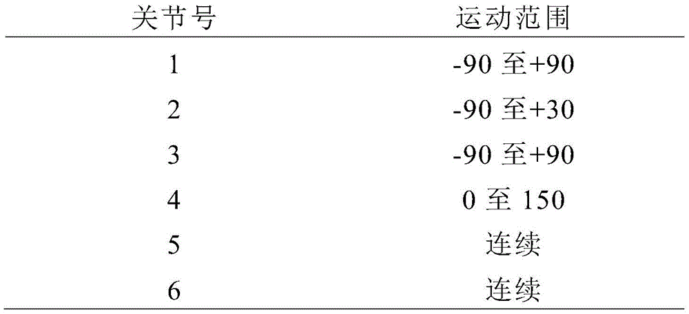
In the embodiment of fig. 14, the shoulder yaw joint 100 actuates the yaw joint 100 in the robot shoulders 14A, 16A. In this embodiment, the robot 10 also has shoulder pitch joints 102, that is, pitch joints 102 on the robot shoulders 14A, 6A. In these embodiments, an upper arm roll joint 104, an elbow joint 106, and a tool roll joint 108 are also provided that allow for a range of motion described in table 1 below. In various embodiments, a tool actuation joint (not shown) interfaces with a tool (not shown) to actuate opening and closing of the tool, as has been previously described.
In various embodiments, these joints 100, 102, 104, 106 have a practically defined range of motion that, together with the robot geometry, results in the final workspace of the robot 10. For the example given herein, the joint constraint allows for a significant robot workspace, as described above. This workspace allows various embodiments of the robot to effectively use the arm and hand simultaneously at several locations within the patient's body cavity. The range of articulation defined in the embodiment of fig. 13A-27 is given in table 1. It should be understood that further ranges are possible, and thus the set of ranges is not limiting, but representative of particular embodiments. Further, alternative embodiments are possible.
The direction of rotation and the zero position are shown in fig. 13A to 13D. In fig. 13A-13D, the robot 10 is shown with each of the first four angles in the zero position. In these embodiments, each joint (shoulder yaw joint 100, shoulder roll joint 102, upper arm roll joint 104, and elbow joint 106) is shown as having an axis of rotation (dotted line) and a zero position. Arrows are then used to indicate the direction of positive joint angle about the axis of rotation. The zero position is arbitrary and not shown, as the tool tumble joint 108 and the tool actuation joint 109 allow for continuous rotation.
Table 1: range of motion of joint
In the embodiment of fig. 14, the body 10A and each linkage (meaning upper arm 16B and forearm 16C) contain a printed circuit board ("PCB") 110, 112, 114 with embedded sensors, amplifiers and control electronics. One PCB is in each forearm and upper arm and two PCBs are in the body. Each PCB also has a complete six-axis accelerometer-based inertial measurement unit and a temperature sensor that can be used to monitor the temperature of the motor. Each joint may also have either or both of an absolute position sensor or an incremental position sensor. In some embodiments, some joints incorporate both absolute position sensors (magnetic encoders) and incremental sensors (hall effect). In other embodiments, some joints have only incremental sensors. These sensors are used for motor control. Each joint may also contain many other types of sensors. A more detailed description of one possible approach is included herein.
In this embodiment, a larger PCB 110 is mounted to the rear side of the body 10A. The body PCB 110 controls motors 116 in the base link or body 10A (shoulder yaw joint 100 and shoulder pitch joint 102 for the left and right arms, respectively). Each upper arm has a PCB112 to control the upper arm roll joint 104 and elbow joint 106. Each forearm has a PCB 114 to control the tool roll joint 108 and the tool actuation joint (not shown). In the embodiment of fig. 14, each PCB 110, 112, 114 also has a complete six-axis accelerometer-based inertial measurement unit and a plurality of temperature sensors that can be used to monitor the temperature of the various motors described herein.
In these embodiments, each joint 100, 102, 104, 106, 108 may also have an absolute position sensor or an incremental position sensor or both, as described and disclosed in U.S. provisional application 61,680,809 filed on 8/2012, the contents of which are incorporated herein by reference in their entirety. In one embodiment, and as shown in fig. 15 and elsewhere, the various actuators or motors 116, 130, 154, 178 described herein have at least one temperature sensor 101 disposed on a surface of the motor (e.g., by a temperature sensitive epoxy) such that the temperature sensor (as shown at 101 in fig. 22) can collect temperature information from each actuator for transmission to a control unit, as discussed below. In one embodiment, any of the motors discussed and described herein may be a brushed or brushless motor. Further, the motor may be, for example, a 6mm, 8mm or 10mm diameter motor. Alternatively, any known size that can be integrated into a medical device may be used. In a further alternative, the actuator may be any known actuator used in medical devices to actuate movement or action of a component. Examples of Motors that may be used for the Motors described herein include an EC 10BLDC + GP10A planetary reducer, an EC 8BLDC + GP8A planetary reducer, or an EC 6BLDC + GP6A planetary reducer, all available from Maxon Motors located in Fall River, MA. There are many ways to actuate these movements, such as using dc motors, ac motors, permanent magnet dc motors, brushless motors, pneumatics, cables to remote motors, hydraulics, and the like. Further embodiments may be used in conjunction with various Systems, Methods, and apparatus disclosed in U.S. patent application No.15/227,813, entitled "rolling scientific Devices, Systems, and Related Methods," filed on 3/8/2016, the contents of which are hereby incorporated by reference in their entirety.
In this embodiment, the joints 1-4 have both absolute position sensors (magnetic encoders) and incremental sensors (hall effect). Joints 5 and 6 have only incremental sensors. These sensors are used for motor control. It should be understood that each joint may also contain many other types of sensors, as has been described in detail in the incorporated applications and references.
According to one embodiment, certain other internal components depicted in the embodiments of fig. 15-16 are configured to actuate rotation of the shoulder yaw joint 100 of the body 10A about the axis 1, as shown in fig. 14. It should be understood that each of the components described uses two internal components-one for each arm-but for ease of description only one internal component is used in certain depictions and descriptions.
As best shown in FIG. 15, the shoulder yaw joint 100, the motor 116 and the reducer combination drive the motor gear 117 a first spur gear set 118, which is best shown in FIG. 16. The first spur gear set 118 drives a shaft supported by a bearing 120 to drive a second spur gear set 122. The second spur gear set 122 in turn drives an output shaft 124 that is also supported by bearings 126. This output shaft 124 then drives the turret 14A, 16A (representing the shoulder of the robot 10) so that the shoulder 16A rotates about the axis 1, as best shown in fig. 14.
According to one embodiment, certain internal components depicted in the embodiment of fig. 17-19 are configured to actuate the shoulder pitch joint 102 and/or the shoulders 14A, 16A of the body 10A about the axis 2, as shown in fig. 14. In these embodiments, the pitch joint 102 is constructed and arranged to pivot the output link 140 to move the upper arm (not shown) relative to the shoulders 14A, 16A.
In this embodiment, the motor 130 and reducer combination drives a motor gear 131 and a spur gear 132, the spur gear 132 in turn driving a first shaft 134. This shaft 134 then drives a pair of bevel (or bevel) gears 136, 137 (depicted in fig. 19) inside the shoulder turntable. The bevel (or bevel) gear pair 136, 137 respectively drives a helical spur gear set 138, 139 directly connected to the shoulder pitch joint 102, output link 140, causing the upper arm 16B to rotate about axis 2, as best shown in fig. 14. In this embodiment, the shoulder yaw joint 100 and the shoulder pitch joint 102 thus have coupled motion. In these embodiments, a plurality of bearings 141 support various gears and other components, as has been previously described.
Fig. 20-23 depict various internal components of the upper arm 16B constructed and arranged for movement and operation of the arm 16. In various embodiments, multiple actuators or motors 142, 154 are disposed within a housing (not shown) of the forearm 16C. Fig. 24-27 depict various internal components of the forearm 16C constructed and arranged for movement and operation of the end effector. In various embodiments, a plurality of actuators or motors 175, 178 are disposed within a housing (not shown) of the forearm 16C.
In one embodiment, and as shown in fig. 22 and elsewhere, the various actuators or motors 116, 130, 154, 178 described herein have at least one temperature sensor 101 disposed on a surface of the motor (e.g., by a temperature sensitive epoxy) such that the temperature sensor can collect temperature information from each actuator for transmission to a control unit, as discussed below. In one embodiment, any of the motors discussed and depicted herein may be a brushed or brushless motor. Further, the motor may be, for example, a 6mm, 8mm or 10mm diameter motor. Alternatively, any known size that can be integrated into a medical device may be used. In a further alternative, the actuator may be any known actuator used in medical devices to actuate movement or action of a component. Examples of Motors that may be used for the Motors described herein include an EC 10BLDC + GP10A planetary reducer, an EC 8BLDC + GP8A planetary reducer, or an EC 6BLDC + GP6A planetary reducer, all available from Maxon Motors located in Fall River, MA. There are many ways to actuate these movements, such as using dc motors, ac motors, permanent magnet dc motors, brushless motors, pneumatics, cables to remote motors, hydraulics, and the like.
One embodiment of the internal components of the upper arm 16B constructed and arranged to actuate the upper arm roll joint 104 is shown in fig. 20-21. In this embodiment, a motor 142 and reducer combination controlled by the PCB112 drives a motor gear 143 and a corresponding spur gear 144, with the output spur gear 144 supported by a shaft 148 and bearings 150. The output shaft 152 and the output spur gear 144 may have mating features 146 that mate to the shoulder pitch joint 102 output link 140 (shown in fig. 17).
One embodiment of the internal components of the upper arm 16B configured to operate the elbow joint 106 is shown in fig. 22-23. In this embodiment, the base motor 154 directly drives a driven spur gear set that includes three gears 156, 158, 160. The spur gear sets 156, 158, 160 transfer the axis of rotation from the axis of the motor 154 to the axis of the worm gear 166.
As best shown in fig. 23, the output spur gear 160 from the set drives a motor reducer 162, which motor reducer 162 drives a worm shaft 164 on which a worm gear 166 is mounted. The worm gear 166 then drives a worm gear 168 which is connected to an output shaft 170 of the joint 4. It should also be noted that the upper arm unit (as shown in fig. 22) shows a curved recessed area 172 on the right side. It should be appreciated that this area 172 is configured to allow greater movement of the joint 4 so as to allow the forearm to pass through the area 172.
One embodiment of the internal components of the forearm 16C configured or otherwise constructed and arranged to operate the tool roll joint 108 is shown in fig. 24-25. In these embodiments, the tool tumble joint 108 drives a tool lumen 174 that holds a tool (e.g., shown at 18, 20 in fig. 1A-1B). The tool lumen 174 is designed to engage a tumbling feature on the tool to cause the tool to rotate about the axis of the tool (shown as axis 5 in fig. 14). In this embodiment, a tool tumbling motor 175 with a reducer is used to drive a motor gear 176 and a spur gear train with two gears 177A, 177B. The last gear 177B of the chain is rigidly mounted to the tool cavity 174 so as to rotate the inner surface 174A of the tool cavity and correspondingly rotate any inserted end effector.
One embodiment of the tool actuation joint 109 is shown in fig. 26-27. In this embodiment, the joints 6, the motors 178 do not visually move the robot. Instead, the tool actuation joint 109 drives a female spline 184 that interfaces with a tool (e.g., shown at 18, 20 in fig. 1A-1B) and is configured to actuate end effector opening and closing. This rotation of the end effector arm that causes the end effector to open and close is also referred to as "tool actuation. In one aspect, actuation occurs as follows. An actuator 178, that is, in this embodiment, a motor assembly 178, is provided. The motor assembly 178 is operatively coupled to a motor gear 180, the motor gear 180 being a spur gear in this embodiment. The motor gear 180 is coupled to the first driven gear 182 and the second driven gear 183 such that rotation of the motor gear 180 causes rotation of the driven gears 182, 183. The driven gears 182, 183 are fixedly coupled to a female tool spline 184 that is supported by a pair of bearings 186. The female tool spline 184 is configured to interface with a male tool spline feature on the end effector to open/close the tool as instructed.
According to one embodiment, an end effector (shown at 18, 20 in fig. 1A-1B) may be quickly and easily coupled to and decoupled from forearm 16C in the following manner. With both the roll axis and the drive axis fixed or held in place, the end effectors 18, 20 may be rotated, thereby coupling or decoupling the threads (not shown). That is, if the end effector is rotated in one direction, the end effector is coupled to the forearm 16B, and if it is rotated in another direction, the end effector is disengaged from the forearm 16B.
Various embodiments of the system 10 are also designed to deliver energy to the end effector to cut and coagulate tissue during surgery. This is sometimes referred to as cauterization and can bring in many electrical forms as well as thermal, ultrasonic and RF energy, all of which are directed to robotics.
In exemplary embodiments of the system 1 and various devices 10, the camera 12 is configured or otherwise constructed and arranged to allow both pitch (meaning "up" and "down") motion and yaw (meaning "side to side" motion) motion within the workspace 30, and in exemplary embodiments, the yaw or "pan" function is accomplished via mechanical articulation at the distal tip 12C rather than via rotating the camera shaft 12D and/or handle 12A as has been previously done. Accordingly, the various embodiments of the camera component 12 of this embodiment have two mechanical degrees of freedom: yaw (left/right looking) and pitch (up/down looking). In use, the camera assembly 12 has pan and tilt functionality powered and controlled by actuators and electronics in the handle 12A, as has been previously described in U.S. patent application No.15/227,813. In these embodiments of the system, the camera 12 can thus allow a user to view the device arm and end effector throughout an extended workspace. Several devices, systems, and methods are described herein that allow for such improved visual range and camera motion.
Various embodiments and components of the camera are shown in fig. 28A-36C and elsewhere. As discussed above, the camera 12 of some embodiments is designed to function with the robot 10, as shown in fig. 2. The robot camera 12 may also be used independently of the robot, as shown in fig. 4. In various embodiments, the camera 12 is inserted into the proximal end 10C of the robot body 10A, and as shown in fig. 28A, the camera tip 12C exits through the distal end 10B of the robot body 10A near the attachment location between the body and the arm, as described above with respect to fig. 6. In certain embodiments, and as discussed with respect to fig. 3, a seal 10E is included in the robot body 10A so that blowing air is not lost when the camera 12 is removed from the robot 10. Several diameters are possible, but one embodiment has a 5mm camera inserted into a 6mm lumen 10D in the robot, as shown in fig. 28A.
In the embodiment of fig. 28A-28B, the camera 12 is designed to bend in two independent degrees of freedom at the distal end 12C. This allows the user to view the robotic tool at any location within the robot workspace via the imager 12B, as shown at 1-V in fig. 28B. In these embodiments, the robot cavity 10D may be centered relative to the robot body 10A, as shown in fig. 28A-28B, which allows for a symmetrical viewpoint relative to the robot arm, or the robot cavity 10D may be more forward, as shown in the embodiment of fig. 1A, or rearward or at other locations.
In addition, as shown in fig. 28A-28B, the distal portion 12C of the camera 12 includes one or more illumination components 12F to illuminate the observation target (as discussed with respect to fig. 1). In these embodiments, the illumination component 12F may be illuminated via a separate light box in the camera handle or some other known light source (not shown, but one non-limiting example is a high brightness LED) or other form of light source. The light may then be directed through the camera shaft 12 via fiber optic cable, as has been previously described, for example, in U.S. patent application No.15/227,813, filed on 2016, 8,3, and entitled "rolling scientific Devices, Systems, and Related Methods," the contents of which are incorporated herein by reference.
Additional features of some embodiments allow camera 12 to be inserted into body 10A at various depths. These embodiments allow for better visualization during various activities. 28C-28E, 28F-28H, and 28I illustrate several embodiments of camera 12 that may be inserted at several depths, which camera 12 may include a fixed position to hold camera 12 using one or more protrusions 70 (such as spring balls 70 disposed on the exterior surface of camera body 12A) and corresponding fixed annular detents 72 (best shown in FIG. 28I) disposed at various depths inside body cavity 10D. In use, detent 72 engages ball 70 at various degrees of insertion depth (see arrow H). This would allow the camera to be more proximal with respect to the robotic arm (fig. 28C-28E) or more distal with respect to the robotic arm (fig. 28F-28H). It should be understood that other methods of positioning camera 12 are possible in alternative embodiments, including continuous motion and other systems actuated with various actuation and control mechanisms.
In various embodiments of the camera handle 12, an overmold may be provided for user comfort. Various connector and button and tail cable combinations are possible. In certain embodiments, the camera handle 12A holds at least one motor to actuate the flexible tip portion 12C. In one version, these motors may then be controlled via a surgical console (as described below) or other input device to control the motion of the camera 12. The control may also include other camera functions such as zoom, brightness, contrast, light intensity, and many other features.
As shown in fig. 29A-29B, flexible articulating tip portion 12C of the camera system allows camera 12 to achieve a field of view (see arrow V) over substantially all of robot workspace 30. In these embodiments, a cross-section of one possible workspace in the sagittal plane is shown. Fig. 29A-29B illustrate that the movement of the robotic arms 14, 16 may move around a large workspace 30 and that the camera system 12 must be able to view the robotic tools 18, 20 at all times.
Fig. 30A-33C depict several embodiments of the apparatus 10 in which the camera 12 may alternatively be oriented to allow consistent tool visualization throughout the operating room. It should be appreciated that this visualization requirement may be met by various embodiments, and that many imager configurations are possible.
The imager 12B-1 of the embodiment of fig. 30A-30F is referred to as a "zero degree range" imager 12B-1, meaning that the viewing line (shown as reference field V) is aligned normal to the distal tip portion 12C of the camera 12. Fig. 30A-30F depict sagittal planes of the robot 10 design, with camera 12C having a zero degree imager 12B-1 that follows the motion of robot 10 from "behind" (at 90 °) (fig. 30A) robot 10 to "below" (at 0 °) (fig. 30D) robot and "in front" (at 90 °) (fig. 30F) robot 602. Fig. 30B, 30C, and 30E depict device 10 at-60 °, 45 °, and 45 °, respectively. It should be appreciated that in the embodiment of fig. 30A-30F, the camera tip portion 12C is oriented to place the end effector 20 into the field of view V at each position.
The imager 12B-2 of the embodiment of fig. 31A-31F is referred to as a "30 degree range" imager 12B-2, meaning that the viewing line (shown at reference region V) is aligned at 30 ° to the distal tip portion 12C of the camera 12, as will be appreciated by those skilled in the art. Fig. 31A-31F depict sagittal planes of the robot 10 design, with camera 12C having a zero degree imager 12B that follows the motion of robot 10 from "behind" (at 90 °) (fig. 31A) robot 10 to "below" (at 0 °) (fig. 31D) robot and "in front" (at 90 °) (fig. 31F) robot 602. Fig. 31B, 31C, and 31E depict device 10 at-60 °, 45 °, and 45 °, respectively. It should be appreciated that in the embodiment of fig. 31A-31F, the camera tip portion 12C is oriented to place the end effector 20 into the field of view V at each position.
The imager 12B-3 of the embodiment of fig. 32A-32F is referred to as a "60 degree range" imager 12B-3, meaning that the viewing line (shown at reference region V) is aligned at 60 ° to the distal tip portion 12C of the camera 12, as will be appreciated by those skilled in the art. Fig. 32A-32F depict sagittal planes of the robot 10 design, with camera 12C having a zero degree imager 12B that follows the motion of robot 10 from "behind" (at 90 °) (fig. 32A) robot 10 to "below" (at 0 °) (fig. 32D) robot and "in front" (at 90 °) (fig. 32F) robot 10. Fig. 32B, 32C and 32E depict the device 10 at-60 °, -45 °, and 45 °, respectively. It should be appreciated that in the embodiment of fig. 32A-32F, the camera tip portion 12C is oriented to place the end effector 20 into the field of view V at each position.
Fig. 33A-33B depict an alternative embodiment of the robot 10 in which the distal camera imager 12B and tip portion 12C may form an "S-curve" shape. This embodiment may require additional degrees of freedom of actuation in some embodiments, but it should be understood that this embodiment has the ability to provide an improved point of view (shown by reference area V) by allowing camera 12B to move from the plane of (or otherwise coaxial with) robot arm 16 and end effector 20. It should be appreciated that offsetting the camera tip portion 12C axis from any individual arm 14, 16 or end effector axis has various advantages, such as for viewing various internal tissues, organs, and the like within an operating room.
Turning to the articulation of the camera tip portion 12C, fig. 34A-34C depict various internal components and devices for effecting the movement of the camera 12 shown in fig. 31A-33B and elsewhere. Also, due to the larger workspace possible in certain embodiments (as discussed at 30, e.g., with respect to fig. 6A-6B), exemplary embodiments of camera 12 are configured or otherwise constructed and arranged to allow both pitch (meaning "up" and "down") motion and roll or yaw (meaning "side-to-side" motion) motion within workspace 30. In these embodiments of the system, the camera can thus allow the user to view the device arm and end effector throughout the extended workspace. Several devices, systems, and methods are described herein that allow for this improved field of view range and camera movement. As will be appreciated by those skilled in the art, the examples of the present invention are non-limiting and are shown for illustrative purposes without a protective sheath (e.g., shown at 15 in fig. 9).
Pitch and yaw articulation of the camera tip portion 12C may be achieved by various embodiments as shown in fig. 34A-34C. Fig. 34A to 34B show a continuous mechanism. In the embodiment of fig. 34A, the camera can be articulated at the tip portion 12C. In this embodiment, the camera tip portion 12C defines a camera lumen 204 via the articulating portion 202 and includes a plurality of openings 206A, 206B on either side of that portion to allow the device to bend in the possible directions (as shown by reference arrows a and B). It should be appreciated that in these embodiments, the articulation portion 202 may be caused to move or articulate in either direction (a or B) via cables 208A, 208B disposed through the camera lumen 204, as well as being actuated via a motor disposed within the camera handle 12A. It should also be understood that additional components such as wires, optical fibers, and the like may also be disposed through the lumen 204.
In the embodiment of fig. 34B, the articulating portion has several spacers 212 surrounding an inner tube 214 defining the camera lumen 204. In these embodiments, a plurality of cables 208A, 208B, 208C, 208D are disposed through openings 216A, 21B, 216C, 216D in spacer 212. As will be appreciated by those skilled in the art, in these embodiments, the cable is fixedly attached to the distal-most spacer 212 and is allowed to pass through the more proximal spacer such that proximal movement of the cable 208 results in articulation of the portion 202. Various Methods for pushing the cable 208 proximally have been previously described, such as described in U.S. patent application No.15/227,813, filed on 3.8.2016 and entitled "rolling Surgical Devices, Systems, and Related Methods," the contents of which are incorporated herein by reference.
The embodiment of fig. 34C has a "stack" of interlocking linkages 220 disposed within the portion 202. In these embodiments, the linkage mechanism 220 has corresponding vertical and horizontal articulation links 222A, 222B on adjacent links 220A, 220B configured to allow appropriate degrees of freedom, as will be understood by those skilled in the art. In these embodiments, a cable (not shown) may extend through the opening 224 in the link 222, as has been previously described. It will be appreciated that these various embodiments of the articulating portion allow adjustment of the camera pitch and yaw in various degrees of freedom to enable the camera to view several fields of view within the workspace without having to reposition the camera body or device.
In addition, the depth to which the camera 12 is inserted into the device 10 may vary. Fig. 35A to 35C show how the depth of the camera 12 can be varied to change the vantage point (refer to arrow V). For example, as shown in fig. 35A, the camera 12 can be fully inserted into the robot 10A with the imager 12B coaxial with the lumen 10D during insertion to "self-visualize" the insertion process. In use, self-visualization allows the user to view the tool tip during insertion. When in this "inserted" position, imager 12B reaches a maximum distance from "line of insertion" 230 (shown by reference arrow A).
As shown in fig. 35B to 35C, a forward working position (fig. 35B) and a backward working position (fig. 35C) are also possible, wherein the field of view (reference region V) is adjusted correspondingly. In the depicted embodiment, the camera 12 movement may be manual or motorized and controlled. As also shown in fig. 35B-35C, in certain embodiments of the device 10 in which the camera extends from a portion on the front side of the device (as shown in fig. 1A), the camera tip depth will vary between forward and rearward viewing positions, as shown by reference arrow B. In certain embodiments, and as also described with respect to fig. 28A-28I, the height of the camera 12 within the workspace may also be adjusted to correct for this difference.
Various embodiments of the system have various tools or end effectors 18, 20 disposed at the distal ends of the arms. Each exemplary embodiment has features of an interchangeable end effector or "hand". In these embodiments, the robotic "hand" may include various tools, such as scissors, graspers, needle drivers, and the like. In various embodiments, each tool is designed to be removable by a small twist of the tool knob 250, for example via an 1/4 bayonet connection. Each tool generally has two actuated and controlled degrees of freedom relative to the forearm. It should be understood that in various embodiments, the tools may also have no degrees of freedom or one or more degrees of freedom. In various embodiments, each tool is controlled via a user input device on the console, as has been previously described. The first degree of freedom allows the tools to roll about their own axis (shown at reference arrow R). One type of tool used in the robot has one degree of freedom. The tools 18, 20 shown in fig. 36A-36B are based on a hook cautery (hook surgery) from a manual laparoscopic tool, and have a tumbling interface 252 and a monopolar slip ring 254. Some embodiments of the tools 18, 20 may be tumbled (see arrow R), but without turning on the closing function. Many additional end effector embodiments are contemplated herein, as described in several incorporated references.
In use, according to some embodiments, the distal end 10B of the device body 10A and the arms 14, 16 are disposed within a patient's body cavity for remote operation by a user via a console, as described below. The user (typically a surgeon) positions the body of the device 10 at a fixed initial starting position within the cavity, and in some embodiments, can thereafter reposition the device as desired. In certain embodiments, and as described herein, the various support systems described herein utilize a "remote centering" or "point tracking" approach to maintain a desired position and orientation of the robot relative to a particular point (e.g., a remote control point and/or an incision or insertion point) by repositioning. In some embodiments, remote control centering is maintained by constraining movement of the support structure as it moves through several degrees of freedom, while some point tracking embodiments impose additional movement on the support structure to maintain position. It should be understood that certain embodiments may involve a combination of these and other approaches. Several illustrative systems and methods for securing, positioning, and repositioning the device 10 are described herein.
As shown in fig. 37, in various embodiments, the robot 10 can be supported in place, fig. 37 showing one method or apparatus for supporting the robot 10 with a known gripping/support system 302 attached to an operating room table 303. The clamping system 302 allows for significant adjustment of the position of the robot in all six degrees of freedom possible for the robot body. It should be understood that other known, commercially available support systems may be used to hold any of the robotic device embodiments disclosed or contemplated herein (e.g., such as the robot 10). Such known devices typically hold manual laparoscopic instruments (e.g., scopes, tools, and retractors) and can similarly be used to grip or otherwise support the robot 10 or other such robotic device embodiments.
Fig. 38-39 illustrate one embodiment of a remote centering mechanism 304, sometimes referred to as a "point tracking mechanism" or "positioning system," that may be used to support the robot 10. According to one embodiment, one advantage of the remote centering mechanism 304 is that the mechanism 304 may be used to move the device 10 while a single point of the robot 10 assembly remains in the same position: the remote center 318 of the mechanism 304 is best shown in fig. 38. In use, mechanism 304 is generally positioned such that remote center 318 is positioned at insertion point 315 in the patient, as best shown in fig. 39. With the remote center 318 at the insertion point 315, the robot 10 has approximately three degrees of freedom around the insertion point 318 and one degree of in/out translational freedom through the insertion point 315 and the port 301. In these embodiments, the insertion point 315 may be adjusted in several ways, such as by moving the mechanism 304 relative to the operating room bed rail to align the remote center 318 with the insertion point 315 on the patient. In one embodiment, the remote center 318 is created by all joints of the mechanism 304 (shown at joints 1, 2, 3, and 4 in fig. 38) that are designed to intersect the remote center 318. As shown in fig. 38, according to one embodiment, joints 1-3 are rotational joints (where joint 2 is a special parallelogram mechanism) and joint 4 is a translational joint that controls the insertion depth of the robot into the abdominal cavity. According to any of the remote centering mechanism embodiments as disclosed or contemplated herein, the remote center 318 may eliminate or reduce mechanical interference between the robot 10 and the abdominal wall 316 that may be generated when the robot 10 is moved.
Fig. 40A and 40B illustrate the positioning of the robot 10 relative to the abdominal wall 316, according to some embodiments. In these embodiments, remote center positioning device 304 (as well as any other positioning device embodiments disclosed or contemplated herein) allows robotic device 10 to access the entire extent of workspace 30 within cavity 316. In these embodiments, the positioning device 304 has several linkages and links 305, 306, 307, 308, 309, including a support link 310 in mechanical communication with the device 10 and joints 311, 312, 313, including a support joint 314 in mechanical communication with the support link 310. In these embodiments, the links 305, 306, 307, 308, 309, 310 and the joints 311, 312, 313, 314 are in mechanical communication with each other and with the support pivot 319 so as to be able to move in at least three degrees of freedom, as well as with rotation of the device 10 (fourth degree of freedom).
That is, the positioning device 304 enables the robotic device 10 to be positioned within the cavity 316 of the patient, with the body 10A of the device 10 positioned through the cutout 315 (or a port provided in the cutout 315) such that the end effectors 18, 20 attached to the arms 14, 16 of the robotic device 10 can reach any desired location in the workspace 30, while the links 305, 306, 307, 308, 309, 310 and joints 311, 312, 313, 314 of the positioning device 304 function to create a remote center 318 at which the device body 10A passes through the cutout 315 such that all movement of the robotic device 22 passes through the remote center 318 at a single point (e.g., insertion point 315). In other words, regardless of the positioning of the links 305, 306, 307, 308, 309, 310 and joints 311, 312, 313, 314, and the resulting positioning of the robotic device 10 within the patient's cavity 316, as a result of the positioning device 304, the portion of the device body 10A at the incision 315 (remote center 318) remains in the same position in all three axes (through the incision 311). This allows for operation of a robotic device (e.g., robotic device 10) within a cavity (e.g., cavity 316) such that an end effector (e.g., end effectors 18, 20) may reach any desired location within the cavity while the entire device 10 is connected to the positioning device 304 via the device body 10A passing through and never moving from a single point (remote center 318) at the cutout 315, thereby enabling operation and positioning of the device 10 through the single cutout (e.g., cutout 315). Another advantage is that the positioning device 304 makes it possible to use a single intra-body robotic device within the patient's cavity instead of the known Da Vinci extending from the patient's cavity and thereby occupying a large amount of working space outside the patient's bodyTMMultiple arms of the system.
Fig. 41A and 41B illustrate a further embodiment of a support device 304 that may be used to support the robot 10. In these embodiments, one or more motors 301A, 301B may be operably integrated with the support mechanism 304 (e.g., links 305, 306, 307, 308, 309, 310 and joints 311, 312, 313, 314). It should be appreciated that in these embodiments, the motors 301A, 301B are capable of driving the respective linkages to various controlled positions, that is, "point tracking" on the incision point 318 with three or four (including device roll) degrees of freedom. That is, the actuators or motors 301A, 301B may be configured to drive the links 305, 306, 307, 308, 309, 310 and joints 311, 312, 313, 314 through yaw, pitch, and rotational degrees of freedom in a coordinated manner so as to maintain the position of the robot 10 relative to the remote control point 318.
According to some embodiments, the support structure 304 of fig. 42A-42C also utilizes one or more motors 301A, 301B to maintain the position of the device 10 relative to the remote control point 318. Also, in these embodiments, the support structure 304 has links 305, 306, 307, 308, 309, 310 and joints 311, 312, 313, 314, including a track joint 326 in operable communication with a pitch track 322 having a track opening 324. It should be appreciated that in these embodiments, movement of the links 305, 306, 307, 308, 309, 310 causes the support joints 326 to pass through various locations on the track openings 324 to reposition the device 10 while point tracking at the remote control point 318. It should be understood that many embodiments of linkages and/or joints are possible.
The embodiments of fig. 43 and 44 depict a positioning and support structure embodiment referred to as a "table lamp" 304. It should be appreciated that this embodiment has similar kinematic features to the table lamp, in that in these embodiments, the links 330, 332, 334, 336, 338, 340, 342, 344, 346 are capable of controlled movement relative to the handle 12A and/or the robot 10 to adjust the pitch or other position of the robot 10 while maintaining a consistent position relative to the insertion point 318. In some embodiments, a spring may be used to offset the weight of the robot 10. As shown in fig. 44, in some of these support devices 304, a plurality of cables 350, 352, 354 may be used to drive a linkage, such as via an actuated spindle 360 or other device. That is, various embodiments, the actuators 301A, 301B can be operably connected to the cables 350, 352, 354 to drive these movements of the links 330, 332, 334, 336, 338, 340, 342, 344, 346.
Of course, all of the support mechanisms described herein may be actuated with a motor or other actuator. Each joint or any combination of joints may be driven by a motor. Sensors may also be used at some or all of the joints to create a control system. The control system may then be connected to the robotic control system so that the support mechanism control and the robotic control may be coordinated to allow the two systems to work together to extend the workspace of the robotic device through robotic control (or other control) on the console or in a separate control system.
In a further alternative embodiment, as shown in fig. 45, the robotic device 10 may be supported by an external robot 360. Here, the robotic device 10 is supported by an external robotic arm 362, the external robotic arm 362 having several links 362, 364, 366 each having one or more degrees of freedom, and may be used to remotely center or point track the robot during a surgical procedure. In various embodiments, the arm(s) are actively controlled by a motor, sensor, and control system (such as described herein). It should be understood that in some embodiments, the external robot 360 may be another surgical robot 360, an industrial robot, or a custom robot. It should also be understood that the external robot 360 of the system 1 may be used in conjunction with other surgical devices and robotic surgical systems, such as laparoscope 365 or other known surgical tools and devices. Another version of the external robot support robot 360 may be a parallel linkage external robot 370, as shown in the embodiment of fig. 46.
The parallel linkage external robot 370 of fig. 46 has an overhead mounted robot 370, which in some embodiments is mounted to the ceiling above the operating room. In various embodiments, a plurality of radially disposed proximal links 372 are actuated by robot 370 via actuation joints 371. These proximal links 372 are in mechanical communication with corresponding knuckles 374, which knuckles 374 in turn support or otherwise position support arms 376. In these embodiments, the support arm is in mechanical and/or operable communication with the surgical robot 10 through the support joint 378 such that movement of the actuation joint 371 is sufficient to urge the support joint laterally, rotationally, and/or vertically in order to urge the robot 10 to various additional positions.
Fig. 47 depicts a further alternative embodiment using a ball joint 380 supported by struts 382 to provide sufficient degrees of freedom for the robot 10 near the insertion point 318. In this embodiment, the spherical joint may be used to accommodate three rotations and one translation (in/out) of the robot 10, as will be appreciated by the skilled person. It should also be understood that in some embodiments, a lever lock may be used to release the ball and allow all four degrees of freedom to move.
As shown in fig. 48A-48D-2, in a further alternative embodiment, a "suspended" support structure 400 is used to support the robot 10. In this embodiment, a curved, pivoting support wand 402 is attached to the operating room table 303 and extends over the patient cavity 316. In this embodiment, the support wand 404 is in operable communication with a suspended articulated "J-hook" 404 that extends over the patient. In this embodiment, the J-hook has an additional telescopic link 406 with ball joints 408, 410 at either end and is used to support and position the robot 10. In various embodiments, and as shown in fig. 48B-1-48D-2, rotational movement of the support wand causes corresponding movement of the J-hook 404 and associated link 406 and joints 408, 410 to "swing" the suspension structure 400 and, in turn, the device 10 about the central location 318. It should be understood that many alternative configurations are possible.
Fig. 49 shows a further alternative embodiment, which shows a rotary support (also referred to as "carousel support") 420 for the robot. In these embodiments, the robot (not shown) is supported by a support arm 422 (e.g., similar to fig. 37), which support arm 422 allows for positioning or adjustment of the support 420 relative to an insertion point 424 in the patient. That is, the support ring 425 is coupled to the distal ends of the support arms 422 and may be positioned adjacent to or on the patient's insertion point 424. As understood in the art, the insertion point 424 may be an incision or a natural orifice in the patient. The support 420 has a "yaw" degree of freedom in the form of a rotating ring 426, which rotating ring 426 is rotatable about an insertion point 424 relative to the support ring 425. In addition, the support 420 has a "pitch" degree of freedom by a cross-link 428 that is rotatable about an axis transverse to the axis of the rotatable ring 426. Coupling plates 430 are rotatably attached to cross-links 428 and are configured to couple to both sides of a robotic device (e.g., such as device 10). According to one embodiment, the coupling plate 430 may be any coupling component capable of coupling to a robotic device. A robot (not shown) may be inserted to different depths using a plate 430, which plate 430 is attached to cross-link 428 with a passive joint that allows for errors around insertion point 424 introduced by variations in abdominal wall thickness. More particularly, each cross-link 428 is rotatably coupled at one end to the rotary ring 426 and at the other end to the plate 430, thereby enabling the robot (e.g., robot 10) to move in order to address any unknown abdominal wall thickness. In one embodiment, the cross-link 428 may be any elongated member that is rotatably coupled to the swivel ring 426 and the coupling plate 430.
An alternative embodiment of a rotational support 440 for a device, such as device 10, is shown in fig. 50A-50D. Here, a support ring 444 supported by two support arms 448 and an open arc pitch track (also referred to herein as a "pitch frame") 446 movably coupled to the ring 444 provide both yaw (y) and pitch (p) degrees of freedom as shown in fig. 50A. More particularly, the pitch track 446 has coupling members 447 that slidably couple to the support ring 444 such that the pitch track 446 can slide along the ring 444 to different positions around the ring 444, as best shown in fig. 50B-50D, thereby providing a yaw (y) degree of freedom for the device 10, wherein the device 10 can rotate about as shown. It should be appreciated that the coupling member 447 can be any mechanism or device that can be slidably coupled to the support ring 444 to allow the pitch track 446 to be couplably slidable along the ring 444 as described herein.
The pitch frame 446 can be slidably positioned on the ring 444 and selectively locked to a desired position or location on the ring 444. Further, a cradle 452 is provided which is slidably coupled to the pitch track 446 and which receives the robotic device 10. That is, the robotic device 10 can be slidably coupled to the carriage 452. The carriage 452 may slide along the pitch track 446 in the direction indicated by reference letter p and may be selectively locked to a desired position or location on the track 446, thereby providing the device 10 with a pitch degree of freedom when coupled to the pitch track 446. In addition, the cradle 452 provides translational freedom for the device 10 because the device 10 is coupled to the cradle 452 such that the device 10 can be slidably positioned in the cradle 452 and selectively locked into a desired position in the cradle. According to one embodiment, the pitch track 446 may be any mechanism or device to which the carriage 452 or robotic device 10 can be slidably coupled so as to provide a degree of freedom in pitch. In this embodiment, the pitch track 446 has a first arm 446A and a second arm 446B, the first arm 446A and the second arm 446B being positioned to define a track space 449 therebetween such that the carriage 452 can be slidably coupled to the first and second arms 446A, 446B and slide along the track space 449. In various embodiments, the two arms 446A, 446B are curved as shown to provide a pitch degree of freedom such that the carriage 452 moves along the arc and thereby transfers the pitch degree of freedom to the device 10.
In certain alternative embodiments, the ring 44 may be supported by one support arm or three or more support arms. In this embodiment, the two support arms 448 are positioned to align the ring 444 with the insertion point 450 (as with other embodiments, the insertion point 450 may be a cut or a natural orifice).
Another embodiment of a robotic device support 460 may be seen in fig. 51. In this embodiment, the device support 460 has two frames: a first frame ("first rail", "pitch frame" or "pitch rail") 462 and a second frame ("second rail", "roll frame" or "roll rail"). The first track 462 is comprised of two arms 462A, 462B positioned to define a track space 463 therebetween such that the second track 464 can be movably coupled to the first and second arms 462A, 462B and moved along the track space 463. In various embodiments, the two arms 462A, 462B are curved into an arc as shown such that the second track 464 moves along the arc. In this embodiment, each of the two arms 462A, 462B has a gear track 465A, 465B coupled to the arms 462A, 462B as shown so that the second track 464 can be coupled to the gear tracks 465A, 465B at each end and thereby move along the two arms 462A, 462B.
The second track 464 is comprised of two arms 464A, 464B positioned to define a track space 467 therebetween such that the carriage 466 can be movably coupled to the first and second arms 464A, 464B and moved along the track space 467. In various embodiments, the two arms 464A, 464B are curved into an arc as shown such that the carriage 466 moves along the arc. In this embodiment, each of the two arms 464A, 464B has a gear track 469A, 469B coupled to the arm 464A, 464B as shown so that the carriage 466 may be coupled to the gear track 469A, 469B and thereby moved along the two arms 464A, 464B. The two arms 464A, 464B have coupling members 468A, 468B at each end thereof that are configured to couple to the arms 462A, 462B of the first frame 462 (and associated gear tracks 465A, 465B). More particularly, in this embodiment, the coupling members 468A, 468B have motors and gears (not shown) that allow the coupling members 468A, 468B to move along the gear tracks 465A, 465B. That is, gears (not shown) in the coupling members 468A, 468B are coupled to the gear tracks 465A, 465B, respectively, and a motor (not shown) may actuate those gears to rotate in the appropriate direction to cause the second track 464 to move along the two arms 462A, 462B of the first track 462.
The cradle 466 is configured to receive the robotic device 10 in a manner similar to the cradle 452 discussed above with reference to fig. 50A-50D. That is, the carriage 466 is movably coupled to the second track 464 and receives the robotic device 10 such that the robotic device 10 can be slidably coupled to the carriage 466. In this embodiment, the carriage 466 has motors and gears (not shown) that allow the carriage 466 to move along the gear tracks 469A, 469B of the second track 464 in a manner similar to the coupling members 468A, 468B described above. Alternatively, the first and second tracks 462, 464 may each be any mechanism or device to which the second track 464 or the bracket 466 can be slidably connected.
According to one embodiment, the two frames 462, 464 may provide three degrees of freedom. That is, the second frame 464 may be moved along the first track space 463 via the coupling members 468A, 468B moving along the first and second arms 462A, 462B, thereby providing the apparatus 10 with a degree of freedom in pitch as indicated by arrow P. Further, carriage 466 may be moved along second track space 467 by moving along first and second arms 464A, 464B, thereby providing device 10 with a degree of roll freedom as indicated by arrow R. Additionally, the device 10 is slidably positioned in the cradle 466 such that the device 10 can be moved translationally toward and away from the surgical space, thereby providing a translational degree of freedom for the device 10. It should also be appreciated that a fourth degree of freedom may be provided to achieve a yaw degree of freedom by coupling the support 460 to a rotatable support ring (e.g., ring 444 discussed above), thereby providing positioning of the robot 10 in three degrees of freedom (pitch, roll, and yaw as described herein) and a translational degree of freedom about the center of rotation 470.
Fig. 52 depicts another support embodiment 500 having a track 502 along which the robotic device 10 may move in a manner similar to the carriage embodiments discussed above. It should be understood that the track 502 may have any of the features described above with respect to other track embodiments. Handle 504 is coupled to one end of track 502 and may translationally slide along track 502 or rotate about track 502. More particularly, the handle 504 has an inner member 504B and an outer member 504A that is slidable relative to the inner member 504B. Further, the handle 504 is coupled to the track 502 such that when the outer member 504A slides relative to the inner member 504B, the outer member 504A moves along the track 502 in the same translational direction as shown by arrow T. For example, when the outer component 504A is pushed distally towards the surgical space (represented by the ball S), the track 502 is also pushed towards the surgical space in the direction as reflected by the arrow T, and when the outer component 504A is pushed apart, the track 502 is also pushed apart. In addition, the entire handle 504 may also be rotated about its own longitudinal axis, thereby urging the track 502 to rotate in the same direction as arrow P, thereby resulting in a degree of freedom in pitch. Further, the device 10 can be slidably or otherwise movably coupled to the track 502 such that the device 10 can be translationally pushed toward or away from the surgical space and can rotate about its own longitudinal axis.
A further support embodiment 520 is depicted in fig. 52B. In this embodiment, the support 520 has two tracks 522, 524 that are coupled or "connected in parallel". That is, the support 520 has a single carriage 526 coupled to both the first and second tracks 522, 524, thereby causing coupled movement of the carriage 526 relative to the two tracks 522, 524. It should be understood that the two tracks 522, 524 may be constructed in a similar manner and have similar features as the previous track embodiments discussed above. Further, the carriage 526 may be similar to the carriage embodiments previously described, except for the fact that the carriage 526 for this example is directly coupled to the two tracks 522, 524 as depicted. That is, in this embodiment, the bracket 526 has two portions (or sections): a top or first portion 526A movably coupled to the second track 524 and a bottom or second portion 526B movably coupled to the first track 522.
As the carriage 526 slides along the first track 522, the second track 524 and the robot 10 rotate as reflected by arrow a. As the carriage 526 slides along the second track 524, the first track 522 and the robot 10 rotate as reflected by arrow B. Further, as in the other carriage embodiments discussed above, the carriage 526 receives the robotic device 10 such that the robotic device 10 can be slidably coupled to the carriage 526, thereby providing a translational degree of freedom for the device 10. Additionally, according to certain embodiments, the two tracks 522, 524 can be coupled to a rotating support ring 528 such that the tracks 522, 524 (and the carriage 526 and the apparatus 10) can each rotate with the ring 528 or relative to the ring 528 in a manner similar to the rotating ring embodiments discussed above.
Fig. 52C depicts a further embodiment of a support 540. In this embodiment, the support 540 has a single track 542 rotatably positioned on a ring support 544. Carriage 546 is movably coupled to track 542. It will be appreciated that track 542 may be constructed in a similar manner and with similar features as the previous track embodiments discussed above. Further, the cradle 546 may be similar to the cradle embodiments previously described.
As carriage 546 slides along track 542, robot 10 rotates as reflected by arrow a. As the track 542 rotates relative to the support ring 544 (or alternatively, the ring 544 rotates), the carriage 546 and the robot 10 rotate as reflected by arrow B. Further, as in the other cradle embodiments discussed above, the cradle 546 receives the robotic device 10 such that the robotic device 10 can be slidably coupled to the cradle 546, thereby providing a translational degree of freedom for the device 10.
Another embodiment of a robotic device support 560 can be seen in fig. 52D. In this embodiment, the device support 560 has two frames: a first frame or rail 562 and a second frame or rail 564. The two frames 562, 564 are coupled to each other in a manner similar to the frames 462, 464 in the support 460 discussed in detail above. That is, the second track 564 can be movably coupled to the first track 562 and move along the first track 562. Either or both of the tracks 562, 564 may have gear tracks as described above. Alternatively, the tracks 562, 564 may have any configuration disclosed or contemplated herein with respect to tracks. In some embodiments, the second track 564 has a coupling feature (not shown) at each end that is configured to be movably coupled to the first frame 562. Alternatively, the second track 546 may be movably coupled to the first track 562 in any manner.
According to one embodiment, the apparatus 10 may be coupled to the support 560 via a bracket (not shown), which may be configured according to any bracket embodiment disclosed or contemplated herein. Alternatively, the device 10 can be directly coupled to the track 564 such that the device 10 can be movably coupled to the track 564. In this way, the device 10 can move along the track 564, as reflected by arrow a, can move towards or away from the surgical space, resulting in translational degrees of freedom as reflected by arrow T, and can rotate about its own longitudinal axis as reflected by arrow R. Additionally, the second track 564 may move along the first track 562, as reflected by arrow B. It should also be appreciated that by coupling the support 560 to a rotatable support ring (such as any of the support ring embodiments discussed above), further degrees of freedom may be provided.
Fig. 52E depicts another embodiment of a support 580. In this embodiment, the support 580 utilizes a spherical joint. That is, the support has a first or upper ring 582 and a second or lower ring 584 coupled by three arms 586A, 586B, 586C. Each of the three arms 586A, 586B, 586C has a spherical joint 588 at each end, such that the three arms 586A, 586B, 586C are coupled at one end to the first ring 582 via the spherical joint 588 and at the other end to the second ring 584 via the spherical joint 588. As shown, the robot 10 is coupled to a second ring 584. In one embodiment, the robot 10 is slidably coupled to the second ring 584 in a manner similar to the above carriage embodiment such that the robot 10 can slide toward or away from the surgical space, thereby resulting in translational degrees of freedom.
It should be appreciated that the configuration of the three arms 586A-586C coupled to the two rings 582, 584 via spherical joints may result in a single center of rotation for the robotic device 10 at some point below the second ring 584. As such, if the support 580 is positioned above the patient, the center of rotation may be aligned with the surgical insertion point (e.g., incision) in a manner similar to the support embodiments above.
A further embodiment of a robotic device support 600 is shown in fig. 52F. In this embodiment, the device support 600 has two frames: a first frame or rail 602 and a second frame or rail 604. The two frames 602, 604 are coupled to each other in a manner similar to the frames 462, 464 of the support 460 or the frames 562, 564 of the support 560, both of which are discussed in detail above. That is, the second rail 604 can be movably coupled to the first rail 602 and move along the first rail 602. The carriage 606 is movably coupled to move along the second track 604. Either or both of the tracks 602, 604 may have gear tracks as described above. Alternatively, the frames 602, 604 may have any configuration disclosed or contemplated herein with respect to the frames. In certain embodiments, the second track 604 has a coupling component 608A, 608B at each end configured to movably couple to the first frame 602. Alternatively, the second track 604 may be movably coupled to the first track 602 in any manner.
The carriage 606 (and thus the apparatus 10) may move along the second frame 604 as reflected by arrow a, may move relative to the carriage 606 towards or away from the surgical space, resulting in a translational degree of freedom as reflected by arrow T, and may rotate about its own longitudinal axis as reflected by arrow R. In addition, the second track 604 may move along the first track 602, as reflected by arrow B. It will also be appreciated that by coupling the support 600 to a rotatable support ring (such as any of the support ring embodiments discussed above), further degrees of freedom may be provided.
One console 720 embodiment is shown in fig. 53 with a main display 722 showing a view from a robot camera (e.g., the robotic device 10). A secondary touch screen 724 below the main display is used to interact with the various functions of the robot, camera and system. In this embodiment, two haptic hand controls 726, 728 are used as user input devices. The haptic hand controllers 726, 728 are capable of measuring the movements of the surgeon's hands as applied at the controllers 726, 728 and applying forces and torques to the hands to indicate various information to the surgeon through the haptic feedback. The console 720 also has pedals 730 to control various functions of the robot. The height of surgical console 720 can be varied to allow the surgeon to sit or stand. Further discussion of the operation of haptic feedback may be found in relation to U.S. patent application nos. 15/227,813, and other applications incorporated herein by reference.
Fig. 54 illustrates various interoperability and wiring possibilities of the system 1. Many concepts are possible, but three exemplary embodiments are presented herein in the context of FIG. 54. In one wired embodiment, surgical console 720 (or any other console disclosed or contemplated herein) interacts with electrosurgical generator 740. A "monster cable" 742 then connects the surgical console 720 to a branch connector 744 near the surgical environment. The camera 746 and robot 10 are then connected to the branch connector 744. In this scenario, the energy of the electrosurgical unit 740 is routed through the surgical console 720 before being sent to the robot 10. In this embodiment, no return pad is provided.
Alternatively, according to another wiring concept. The return pad 748 is configured to be coupled to the branch connector 744 such that monopolar electrosurgical energy is routed through the branch connector 744, the magic acoustic cable 742, and the console 720 before returning to the electrosurgical generator 740.
In a further wiring alternative, the return pad 748 is coupled to the electrosurgical generator 740 such that energy of the electrosurgical unit is routed through the surgical console 720 before being sent to the robot 10 as monopolar electrosurgical energy is routed directly back to the electrosurgical generator 740.
In other embodiments, the system 1 may have a cable connector housing or cluster with an interface box positioned at one of several possible locations on the system 1. For example, fig. 55 depicts a system 1 having an interface cassette (also referred to herein as a "cassette") 760 suspended from a rail of a surgical table 762. In this embodiment, the system 1 has supporting electronics and devices, such as cauterization, lighting and other functions 764 coupled to the interface box 760. The console 720 is also coupled to an interface box 760. The cartridge 760 simplifies the connection of the robot 1 in the surgical field. The cassette 760 may be sterile, or not sterile and covered with sterile drapes, or not sterile at all. The function of the cassette 760 is to simplify the wiring required in the surgical space and to simplify the connection of the robot and camera 1 to the surgical console 720. The interface box 760 can be suspended on the surgical table 762 inside or outside the sterile field. In some embodiments, the case 760 has an indicator, such as a light or screen (not shown), that informs the user that the appropriate connection has been made and provides other forms of feedback to the user. The case 760 may also have an interface in the form of buttons, a touch screen, or other interface mechanisms to receive input from a user.
In certain alternative embodiments, the cassette 760 can be placed on a floor near the surgical table 762 or at a distance from the surgical table 762. Alternatively, the cassette 760 can be hung or connected to other locations or placed on the floor outside the sterile field.
One use of this is to mount the cassette to a bed rail and then bring a sterile robot and camera at a later time. The robot and camera tail cables can then be handed to non-sterile personnel for connection to the cassette. This allows for a clean interface between the sterile field and the non-sterile field. The cassette end can also be covered by a drape so that it can be brought into a sterile field and the robot and camera connection can be assembled at a sterile station so it can be provided fully functional and sterile to the surgeon at the bedside.
The interface box can also be connected to other supporting electronics and equipment, such as cauterization, lighting, and other functions, and the interface box can be designed to be on the floor or another location outside of the sterile field with the supporting electronics.
Although the present disclosure has been described with reference to preferred embodiments, workers skilled in the art will recognize that changes may be made in form and detail without departing from the spirit and scope of the disclosed apparatus, system, and method.
Claims (20)
Priority Applications (1)
| Application Number | Priority Date | Filing Date | Title |
|---|---|---|---|
| CN202111220047.5A CN114098975A (en) | 2016-05-18 | 2017-05-18 | Robotic surgical devices, systems, and related methods |
Applications Claiming Priority (3)
| Application Number | Priority Date | Filing Date | Title |
|---|---|---|---|
| US201662338375P | 2016-05-18 | 2016-05-18 | |
| US62/338,375 | 2016-05-18 | ||
| PCT/US2017/033368 WO2017201310A1 (en) | 2016-05-18 | 2017-05-18 | Robotic surgicla devices, systems and related methods |
Related Child Applications (1)
| Application Number | Title | Priority Date | Filing Date |
|---|---|---|---|
| CN202111220047.5A Division CN114098975A (en) | 2016-05-18 | 2017-05-18 | Robotic surgical devices, systems, and related methods |
Publications (2)
| Publication Number | Publication Date |
|---|---|
| CN109715081A CN109715081A (en) | 2019-05-03 |
| CN109715081B true CN109715081B (en) | 2021-11-09 |
Family
ID=60325663
Family Applications (2)
| Application Number | Title | Priority Date | Filing Date |
|---|---|---|---|
| CN202111220047.5A Pending CN114098975A (en) | 2016-05-18 | 2017-05-18 | Robotic surgical devices, systems, and related methods |
| CN201780044266.8A Active CN109715081B (en) | 2016-05-18 | 2017-05-18 | Robotic surgical devices, systems, and related methods |
Family Applications Before (1)
| Application Number | Title | Priority Date | Filing Date |
|---|---|---|---|
| CN202111220047.5A Pending CN114098975A (en) | 2016-05-18 | 2017-05-18 | Robotic surgical devices, systems, and related methods |
Country Status (6)
| Country | Link |
|---|---|
| US (4) | US10751136B2 (en) |
| EP (2) | EP3457951B1 (en) |
| JP (3) | JP7176757B2 (en) |
| CN (2) | CN114098975A (en) |
| CA (1) | CA3024623A1 (en) |
| WO (1) | WO2017201310A1 (en) |
Families Citing this family (194)
| Publication number | Priority date | Publication date | Assignee | Title |
|---|---|---|---|---|
| CA2838637C (en) | 2011-06-10 | 2020-11-17 | Board Of Regents Of The University Of Nebraska | Methods, systems, and devices relating to surgical end effectors |
| JP6106169B2 (en) | 2011-07-11 | 2017-03-29 | ボード オブ リージェンツ オブ ザ ユニバーシティ オブ ネブラスカ | Surgical robot system |
| US10582973B2 (en) | 2012-08-08 | 2020-03-10 | Virtual Incision Corporation | Robotic surgical devices, systems, and related methods |
| EP2882330B1 (en) | 2011-10-03 | 2020-05-13 | Board of Regents of the University of Nebraska | Robotic surgical devices and systems |
| CA2871149C (en) | 2012-05-01 | 2020-08-25 | Board Of Regents Of The University Of Nebraska | Single site robotic device and related systems and methods |
| US11871901B2 (en) | 2012-05-20 | 2024-01-16 | Cilag Gmbh International | Method for situational awareness for surgical network or surgical network connected device capable of adjusting function based on a sensed situation or usage |
| JP6228196B2 (en) | 2012-06-22 | 2017-11-08 | ボード オブ リージェンツ オブ ザ ユニバーシティ オブ ネブラスカ | Locally controlled robotic surgical device |
| US12295680B2 (en) | 2012-08-08 | 2025-05-13 | Board Of Regents Of The University Of Nebraska | Robotic surgical devices, systems and related methods |
| US9888966B2 (en) | 2013-03-14 | 2018-02-13 | Board Of Regents Of The University Of Nebraska | Methods, systems, and devices relating to force control surgical systems |
| US9743987B2 (en) | 2013-03-14 | 2017-08-29 | Board Of Regents Of The University Of Nebraska | Methods, systems, and devices relating to robotic surgical devices, end effectors, and controllers |
| CA2906772C (en) * | 2013-03-15 | 2021-09-21 | Board Of Regents Of The University Of Nebraska | Robotic surgical devices, systems and related methods |
| CA2918531A1 (en) | 2013-07-17 | 2015-01-22 | Board Of Regents Of The University Of Nebraska | Robotic surgical devices, systems and related methods |
| US9895200B2 (en) | 2014-04-22 | 2018-02-20 | Bio-Medical Engineering (HK) Limited | Robotic devices and systems for performing single incision procedures and natural orifice translumenal endoscopic surgical procedures, and methods of configuring robotic devices and systems |
| WO2015161677A1 (en) | 2014-04-22 | 2015-10-29 | Bio-Medical Engineering (HK) Limited | Single access surgical robotic devices and systems, and methods of configuring single access surgical robotic devices and systems |
| US11154368B2 (en) | 2014-04-22 | 2021-10-26 | Bio-Medical Engineering (HK) Limited | Port assembly for use with robotic devices and systems to perform single incision procedures and natural orifice translumenal endoscopic surgical procedures |
| US10500008B2 (en) | 2014-04-22 | 2019-12-10 | Bio-Medical Engineering (HK) Limited | Surgical arm system with internally driven gear assemblies |
| US11801099B2 (en) | 2014-04-22 | 2023-10-31 | Bio-Medical Engineering (HK) Limited | Robotic devices and systems for performing single incision procedures and natural orifice translumenal endoscopic surgical procedures, and methods of configuring robotic devices and systems |
| US11090123B2 (en) | 2014-04-22 | 2021-08-17 | Bio-Medical Engineering (HK) Limited | Robotic devices and systems for performing single incision procedures and natural orifice translumenal endoscopic surgical procedures, and methods of configuring robotic devices and systems |
| US10342561B2 (en) | 2014-09-12 | 2019-07-09 | Board Of Regents Of The University Of Nebraska | Quick-release end effectors and related systems and methods |
| US11504192B2 (en) | 2014-10-30 | 2022-11-22 | Cilag Gmbh International | Method of hub communication with surgical instrument systems |
| WO2016077478A1 (en) | 2014-11-11 | 2016-05-19 | Board Of Regents Of The University Of Nebraska | Robotic device with compact joint design and related systems and methods |
| EP4555965A3 (en) | 2015-08-03 | 2025-07-02 | Virtual Incision Corporation | Robotic surgical devices, systems and related methods |
| ITUB20155057A1 (en) | 2015-10-16 | 2017-04-16 | Medical Microinstruments S R L | Robotic surgery set |
| JP7176757B2 (en) * | 2016-05-18 | 2022-11-22 | バーチャル インシジョン コーポレイション | ROBOTIC SURGICAL DEVICES, SYSTEMS AND RELATED METHODS |
| CA3022165A1 (en) * | 2016-05-26 | 2017-11-30 | Covidien Lp | Robotic surgical assemblies and instrument drive units thereof |
| WO2018039606A1 (en) | 2016-08-25 | 2018-03-01 | Virtual Incision Corporation | Quick-release tool coupler and related systems and methods |
| JP7090615B2 (en) | 2016-08-30 | 2022-06-24 | ボード オブ リージェンツ オブ ザ ユニバーシティ オブ ネブラスカ | Robot device |
| CN115337111B (en) | 2016-11-22 | 2025-04-25 | 内布拉斯加大学董事会 | Improved coarse positioning device and related system and method |
| CN110462259B (en) | 2016-11-29 | 2022-10-28 | 虚拟切割有限公司 | User controller with user presence detection and related systems and methods |
| US10722319B2 (en) | 2016-12-14 | 2020-07-28 | Virtual Incision Corporation | Releasable attachment device for coupling to medical devices and related systems and methods |
| DK3672472T3 (en) | 2017-08-23 | 2022-11-21 | Momentis Surgical Ltd | TOOLS FOR VAGINAL ACCESS |
| US11051894B2 (en) | 2017-09-27 | 2021-07-06 | Virtual Incision Corporation | Robotic surgical devices with tracking camera technology and related systems and methods |
| US11317919B2 (en) | 2017-10-30 | 2022-05-03 | Cilag Gmbh International | Clip applier comprising a clip crimping system |
| US11510741B2 (en) | 2017-10-30 | 2022-11-29 | Cilag Gmbh International | Method for producing a surgical instrument comprising a smart electrical system |
| US11291510B2 (en) | 2017-10-30 | 2022-04-05 | Cilag Gmbh International | Method of hub communication with surgical instrument systems |
| US11564756B2 (en) | 2017-10-30 | 2023-01-31 | Cilag Gmbh International | Method of hub communication with surgical instrument systems |
| US11801098B2 (en) | 2017-10-30 | 2023-10-31 | Cilag Gmbh International | Method of hub communication with surgical instrument systems |
| US11229436B2 (en) | 2017-10-30 | 2022-01-25 | Cilag Gmbh International | Surgical system comprising a surgical tool and a surgical hub |
| US11051836B2 (en) | 2017-10-30 | 2021-07-06 | Cilag Gmbh International | Surgical clip applier comprising an empty clip cartridge lockout |
| US11911045B2 (en) | 2017-10-30 | 2024-02-27 | Cllag GmbH International | Method for operating a powered articulating multi-clip applier |
| US11045197B2 (en) | 2017-10-30 | 2021-06-29 | Cilag Gmbh International | Clip applier comprising a movable clip magazine |
| US11311342B2 (en) | 2017-10-30 | 2022-04-26 | Cilag Gmbh International | Method for communicating with surgical instrument systems |
| US11202570B2 (en) | 2017-12-28 | 2021-12-21 | Cilag Gmbh International | Communication hub and storage device for storing parameters and status of a surgical device to be shared with cloud based analytics systems |
| US11056244B2 (en) | 2017-12-28 | 2021-07-06 | Cilag Gmbh International | Automated data scaling, alignment, and organizing based on predefined parameters within surgical networks |
| US11602393B2 (en) | 2017-12-28 | 2023-03-14 | Cilag Gmbh International | Surgical evacuation sensing and generator control |
| US11896322B2 (en) | 2017-12-28 | 2024-02-13 | Cilag Gmbh International | Sensing the patient position and contact utilizing the mono-polar return pad electrode to provide situational awareness to the hub |
| US11160605B2 (en) | 2017-12-28 | 2021-11-02 | Cilag Gmbh International | Surgical evacuation sensing and motor control |
| US11744604B2 (en) | 2017-12-28 | 2023-09-05 | Cilag Gmbh International | Surgical instrument with a hardware-only control circuit |
| US11304720B2 (en) | 2017-12-28 | 2022-04-19 | Cilag Gmbh International | Activation of energy devices |
| US11257589B2 (en) | 2017-12-28 | 2022-02-22 | Cilag Gmbh International | Real-time analysis of comprehensive cost of all instrumentation used in surgery utilizing data fluidity to track instruments through stocking and in-house processes |
| US11633237B2 (en) | 2017-12-28 | 2023-04-25 | Cilag Gmbh International | Usage and technique analysis of surgeon / staff performance against a baseline to optimize device utilization and performance for both current and future procedures |
| BR112020013021A2 (en) | 2017-12-28 | 2020-11-24 | Ethicon Llc | adjustment of a function of the surgical device based on situational recognition |
| US11818052B2 (en) | 2017-12-28 | 2023-11-14 | Cilag Gmbh International | Surgical network determination of prioritization of communication, interaction, or processing based on system or device needs |
| US11026751B2 (en) | 2017-12-28 | 2021-06-08 | Cilag Gmbh International | Display of alignment of staple cartridge to prior linear staple line |
| US11423007B2 (en) | 2017-12-28 | 2022-08-23 | Cilag Gmbh International | Adjustment of device control programs based on stratified contextual data in addition to the data |
| US11857152B2 (en) | 2017-12-28 | 2024-01-02 | Cilag Gmbh International | Surgical hub spatial awareness to determine devices in operating theater |
| US11903601B2 (en) | 2017-12-28 | 2024-02-20 | Cilag Gmbh International | Surgical instrument comprising a plurality of drive systems |
| US10943454B2 (en) | 2017-12-28 | 2021-03-09 | Ethicon Llc | Detection and escalation of security responses of surgical instruments to increasing severity threats |
| US10944728B2 (en) | 2017-12-28 | 2021-03-09 | Ethicon Llc | Interactive surgical systems with encrypted communication capabilities |
| US11051876B2 (en) | 2017-12-28 | 2021-07-06 | Cilag Gmbh International | Surgical evacuation flow paths |
| US11832840B2 (en) | 2017-12-28 | 2023-12-05 | Cilag Gmbh International | Surgical instrument having a flexible circuit |
| US10595887B2 (en) | 2017-12-28 | 2020-03-24 | Ethicon Llc | Systems for adjusting end effector parameters based on perioperative information |
| US11076921B2 (en) | 2017-12-28 | 2021-08-03 | Cilag Gmbh International | Adaptive control program updates for surgical hubs |
| US11571234B2 (en) | 2017-12-28 | 2023-02-07 | Cilag Gmbh International | Temperature control of ultrasonic end effector and control system therefor |
| US11896443B2 (en) | 2017-12-28 | 2024-02-13 | Cilag Gmbh International | Control of a surgical system through a surgical barrier |
| US10987178B2 (en) | 2017-12-28 | 2021-04-27 | Ethicon Llc | Surgical hub control arrangements |
| US12062442B2 (en) | 2017-12-28 | 2024-08-13 | Cilag Gmbh International | Method for operating surgical instrument systems |
| US11253315B2 (en) | 2017-12-28 | 2022-02-22 | Cilag Gmbh International | Increasing radio frequency to create pad-less monopolar loop |
| US11589888B2 (en) | 2017-12-28 | 2023-02-28 | Cilag Gmbh International | Method for controlling smart energy devices |
| US11419630B2 (en) | 2017-12-28 | 2022-08-23 | Cilag Gmbh International | Surgical system distributed processing |
| US11234756B2 (en) | 2017-12-28 | 2022-02-01 | Cilag Gmbh International | Powered surgical tool with predefined adjustable control algorithm for controlling end effector parameter |
| US11100631B2 (en) | 2017-12-28 | 2021-08-24 | Cilag Gmbh International | Use of laser light and red-green-blue coloration to determine properties of back scattered light |
| US11013563B2 (en) | 2017-12-28 | 2021-05-25 | Ethicon Llc | Drive arrangements for robot-assisted surgical platforms |
| US11666331B2 (en) | 2017-12-28 | 2023-06-06 | Cilag Gmbh International | Systems for detecting proximity of surgical end effector to cancerous tissue |
| US11844579B2 (en) | 2017-12-28 | 2023-12-19 | Cilag Gmbh International | Adjustments based on airborne particle properties |
| US11529187B2 (en) | 2017-12-28 | 2022-12-20 | Cilag Gmbh International | Surgical evacuation sensor arrangements |
| US20190206569A1 (en) | 2017-12-28 | 2019-07-04 | Ethicon Llc | Method of cloud based data analytics for use with the hub |
| US10758310B2 (en) | 2017-12-28 | 2020-09-01 | Ethicon Llc | Wireless pairing of a surgical device with another device within a sterile surgical field based on the usage and situational awareness of devices |
| WO2019133144A1 (en) | 2017-12-28 | 2019-07-04 | Ethicon Llc | Detection and escalation of security responses of surgical instruments to increasing severity threats |
| US10849697B2 (en) | 2017-12-28 | 2020-12-01 | Ethicon Llc | Cloud interface for coupled surgical devices |
| US11069012B2 (en) | 2017-12-28 | 2021-07-20 | Cilag Gmbh International | Interactive surgical systems with condition handling of devices and data capabilities |
| US11109866B2 (en) | 2017-12-28 | 2021-09-07 | Cilag Gmbh International | Method for circular stapler control algorithm adjustment based on situational awareness |
| US11969142B2 (en) | 2017-12-28 | 2024-04-30 | Cilag Gmbh International | Method of compressing tissue within a stapling device and simultaneously displaying the location of the tissue within the jaws |
| US10695081B2 (en) | 2017-12-28 | 2020-06-30 | Ethicon Llc | Controlling a surgical instrument according to sensed closure parameters |
| US12096916B2 (en) | 2017-12-28 | 2024-09-24 | Cilag Gmbh International | Method of sensing particulate from smoke evacuated from a patient, adjusting the pump speed based on the sensed information, and communicating the functional parameters of the system to the hub |
| US11786245B2 (en) | 2017-12-28 | 2023-10-17 | Cilag Gmbh International | Surgical systems with prioritized data transmission capabilities |
| US12458351B2 (en) | 2017-12-28 | 2025-11-04 | Cilag Gmbh International | Variable output cartridge sensor assembly |
| US11278281B2 (en) | 2017-12-28 | 2022-03-22 | Cilag Gmbh International | Interactive surgical system |
| US10892899B2 (en) | 2017-12-28 | 2021-01-12 | Ethicon Llc | Self describing data packets generated at an issuing instrument |
| US10898622B2 (en) | 2017-12-28 | 2021-01-26 | Ethicon Llc | Surgical evacuation system with a communication circuit for communication between a filter and a smoke evacuation device |
| US11284936B2 (en) | 2017-12-28 | 2022-03-29 | Cilag Gmbh International | Surgical instrument having a flexible electrode |
| US20190201042A1 (en) | 2017-12-28 | 2019-07-04 | Ethicon Llc | Determining the state of an ultrasonic electromechanical system according to frequency shift |
| US20190201118A1 (en) | 2017-12-28 | 2019-07-04 | Ethicon Llc | Display arrangements for robot-assisted surgical platforms |
| US11166772B2 (en) | 2017-12-28 | 2021-11-09 | Cilag Gmbh International | Surgical hub coordination of control and communication of operating room devices |
| US11389164B2 (en) | 2017-12-28 | 2022-07-19 | Cilag Gmbh International | Method of using reinforced flexible circuits with multiple sensors to optimize performance of radio frequency devices |
| US11419667B2 (en) | 2017-12-28 | 2022-08-23 | Cilag Gmbh International | Ultrasonic energy device which varies pressure applied by clamp arm to provide threshold control pressure at a cut progression location |
| US11659023B2 (en) | 2017-12-28 | 2023-05-23 | Cilag Gmbh International | Method of hub communication |
| US11864728B2 (en) | 2017-12-28 | 2024-01-09 | Cilag Gmbh International | Characterization of tissue irregularities through the use of mono-chromatic light refractivity |
| US11464559B2 (en) | 2017-12-28 | 2022-10-11 | Cilag Gmbh International | Estimating state of ultrasonic end effector and control system therefor |
| US11678881B2 (en) | 2017-12-28 | 2023-06-20 | Cilag Gmbh International | Spatial awareness of surgical hubs in operating rooms |
| US20190201087A1 (en) | 2017-12-28 | 2019-07-04 | Ethicon Llc | Smoke evacuation system including a segmented control circuit for interactive surgical platform |
| US11937769B2 (en) | 2017-12-28 | 2024-03-26 | Cilag Gmbh International | Method of hub communication, processing, storage and display |
| US11446052B2 (en) | 2017-12-28 | 2022-09-20 | Cilag Gmbh International | Variation of radio frequency and ultrasonic power level in cooperation with varying clamp arm pressure to achieve predefined heat flux or power applied to tissue |
| US11559308B2 (en) | 2017-12-28 | 2023-01-24 | Cilag Gmbh International | Method for smart energy device infrastructure |
| US11376002B2 (en) | 2017-12-28 | 2022-07-05 | Cilag Gmbh International | Surgical instrument cartridge sensor assemblies |
| US12376855B2 (en) | 2017-12-28 | 2025-08-05 | Cilag Gmbh International | Safety systems for smart powered surgical stapling |
| US11410259B2 (en) | 2017-12-28 | 2022-08-09 | Cilag Gmbh International | Adaptive control program updates for surgical devices |
| US11786251B2 (en) | 2017-12-28 | 2023-10-17 | Cilag Gmbh International | Method for adaptive control schemes for surgical network control and interaction |
| US20190201112A1 (en) | 2017-12-28 | 2019-07-04 | Ethicon Llc | Computer implemented interactive surgical systems |
| US11424027B2 (en) | 2017-12-28 | 2022-08-23 | Cilag Gmbh International | Method for operating surgical instrument systems |
| US11096693B2 (en) | 2017-12-28 | 2021-08-24 | Cilag Gmbh International | Adjustment of staple height of at least one row of staples based on the sensed tissue thickness or force in closing |
| US11559307B2 (en) | 2017-12-28 | 2023-01-24 | Cilag Gmbh International | Method of robotic hub communication, detection, and control |
| US11832899B2 (en) | 2017-12-28 | 2023-12-05 | Cilag Gmbh International | Surgical systems with autonomously adjustable control programs |
| US20190201090A1 (en) | 2017-12-28 | 2019-07-04 | Ethicon Llc | Capacitive coupled return path pad with separable array elements |
| US11266468B2 (en) | 2017-12-28 | 2022-03-08 | Cilag Gmbh International | Cooperative utilization of data derived from secondary sources by intelligent surgical hubs |
| US12396806B2 (en) | 2017-12-28 | 2025-08-26 | Cilag Gmbh International | Adjustment of a surgical device function based on situational awareness |
| US11291495B2 (en) | 2017-12-28 | 2022-04-05 | Cilag Gmbh International | Interruption of energy due to inadvertent capacitive coupling |
| US12127729B2 (en) | 2017-12-28 | 2024-10-29 | Cilag Gmbh International | Method for smoke evacuation for surgical hub |
| US10932872B2 (en) | 2017-12-28 | 2021-03-02 | Ethicon Llc | Cloud-based medical analytics for linking of local usage trends with the resource acquisition behaviors of larger data set |
| US10966791B2 (en) | 2017-12-28 | 2021-04-06 | Ethicon Llc | Cloud-based medical analytics for medical facility segmented individualization of instrument function |
| US11576677B2 (en) | 2017-12-28 | 2023-02-14 | Cilag Gmbh International | Method of hub communication, processing, display, and cloud analytics |
| US11540855B2 (en) | 2017-12-28 | 2023-01-03 | Cilag Gmbh International | Controlling activation of an ultrasonic surgical instrument according to the presence of tissue |
| US11273001B2 (en) | 2017-12-28 | 2022-03-15 | Cilag Gmbh International | Surgical hub and modular device response adjustment based on situational awareness |
| US11969216B2 (en) | 2017-12-28 | 2024-04-30 | Cilag Gmbh International | Surgical network recommendations from real time analysis of procedure variables against a baseline highlighting differences from the optimal solution |
| US11304763B2 (en) | 2017-12-28 | 2022-04-19 | Cilag Gmbh International | Image capturing of the areas outside the abdomen to improve placement and control of a surgical device in use |
| US11304699B2 (en) | 2017-12-28 | 2022-04-19 | Cilag Gmbh International | Method for adaptive control schemes for surgical network control and interaction |
| US11308075B2 (en) | 2017-12-28 | 2022-04-19 | Cilag Gmbh International | Surgical network, instrument, and cloud responses based on validation of received dataset and authentication of its source and integrity |
| US11179208B2 (en) | 2017-12-28 | 2021-11-23 | Cilag Gmbh International | Cloud-based medical analytics for security and authentication trends and reactive measures |
| US11998193B2 (en) | 2017-12-28 | 2024-06-04 | Cilag Gmbh International | Method for usage of the shroud as an aspect of sensing or controlling a powered surgical device, and a control algorithm to adjust its default operation |
| US10918310B2 (en) | 2018-01-03 | 2021-02-16 | Biosense Webster (Israel) Ltd. | Fast anatomical mapping (FAM) using volume filling |
| US11304745B2 (en) | 2017-12-28 | 2022-04-19 | Cilag Gmbh International | Surgical evacuation sensing and display |
| US11311306B2 (en) | 2017-12-28 | 2022-04-26 | Cilag Gmbh International | Surgical systems for detecting end effector tissue distribution irregularities |
| US11364075B2 (en) | 2017-12-28 | 2022-06-21 | Cilag Gmbh International | Radio frequency energy device for delivering combined electrical signals |
| US11147607B2 (en) | 2017-12-28 | 2021-10-19 | Cilag Gmbh International | Bipolar combination device that automatically adjusts pressure based on energy modality |
| US20190201039A1 (en) | 2017-12-28 | 2019-07-04 | Ethicon Llc | Situational awareness of electrosurgical systems |
| US11324557B2 (en) | 2017-12-28 | 2022-05-10 | Cilag Gmbh International | Surgical instrument with a sensing array |
| US11432885B2 (en) | 2017-12-28 | 2022-09-06 | Cilag Gmbh International | Sensing arrangements for robot-assisted surgical platforms |
| US11464535B2 (en) | 2017-12-28 | 2022-10-11 | Cilag Gmbh International | Detection of end effector emersion in liquid |
| US11317937B2 (en) | 2018-03-08 | 2022-05-03 | Cilag Gmbh International | Determining the state of an ultrasonic end effector |
| US11132462B2 (en) | 2017-12-28 | 2021-09-28 | Cilag Gmbh International | Data stripping method to interrogate patient records and create anonymized record |
| US10892995B2 (en) | 2017-12-28 | 2021-01-12 | Ethicon Llc | Surgical network determination of prioritization of communication, interaction, or processing based on system or device needs |
| CN117140580A (en) | 2018-01-05 | 2023-12-01 | 内布拉斯加大学董事会 | Single-arm robotic device with compact joint design and related systems and methods |
| US20200352658A1 (en) * | 2018-01-05 | 2020-11-12 | Medrobotics Corporation | User interface for robotic surgical system |
| US11986233B2 (en) | 2018-03-08 | 2024-05-21 | Cilag Gmbh International | Adjustment of complex impedance to compensate for lost power in an articulating ultrasonic device |
| US11298148B2 (en) | 2018-03-08 | 2022-04-12 | Cilag Gmbh International | Live time tissue classification using electrical parameters |
| US11259830B2 (en) | 2018-03-08 | 2022-03-01 | Cilag Gmbh International | Methods for controlling temperature in ultrasonic device |
| US12303159B2 (en) | 2018-03-08 | 2025-05-20 | Cilag Gmbh International | Methods for estimating and controlling state of ultrasonic end effector |
| CN108567489B (en) * | 2018-03-23 | 2022-05-13 | 深圳市精锋医疗科技股份有限公司 | Operation arm, slave operation device and surgical robot |
| US11207067B2 (en) | 2018-03-28 | 2021-12-28 | Cilag Gmbh International | Surgical stapling device with separate rotary driven closure and firing systems and firing member that engages both jaws while firing |
| US11096688B2 (en) | 2018-03-28 | 2021-08-24 | Cilag Gmbh International | Rotary driven firing members with different anvil and channel engagement features |
| US10973520B2 (en) | 2018-03-28 | 2021-04-13 | Ethicon Llc | Surgical staple cartridge with firing member driven camming assembly that has an onboard tissue cutting feature |
| US11219453B2 (en) | 2018-03-28 | 2022-01-11 | Cilag Gmbh International | Surgical stapling devices with cartridge compatible closure and firing lockout arrangements |
| US11166716B2 (en) | 2018-03-28 | 2021-11-09 | Cilag Gmbh International | Stapling instrument comprising a deactivatable lockout |
| US11471156B2 (en) | 2018-03-28 | 2022-10-18 | Cilag Gmbh International | Surgical stapling devices with improved rotary driven closure systems |
| US11259806B2 (en) | 2018-03-28 | 2022-03-01 | Cilag Gmbh International | Surgical stapling devices with features for blocking advancement of a camming assembly of an incompatible cartridge installed therein |
| US11278280B2 (en) | 2018-03-28 | 2022-03-22 | Cilag Gmbh International | Surgical instrument comprising a jaw closure lockout |
| US11090047B2 (en) | 2018-03-28 | 2021-08-17 | Cilag Gmbh International | Surgical instrument comprising an adaptive control system |
| CN210185692U (en) * | 2018-07-31 | 2020-03-27 | 深圳市精锋医疗科技有限公司 | Adjustable slave operation equipment assembly and surgical robot |
| US11992929B2 (en) | 2018-09-18 | 2024-05-28 | Brigham Young University | Developable and collapsible shaft deployment mechanism |
| CN112955078B (en) * | 2018-09-18 | 2023-10-27 | 布莱阿姆青年大学 | Expandable and foldable internal cutting mechanism |
| ES2968488T3 (en) | 2018-09-18 | 2024-05-09 | Univ Brigham Young | External folding and deployable cutting or holding mechanism |
| WO2020072328A1 (en) * | 2018-10-02 | 2020-04-09 | Convergascent Llc | Endoscope with inertial measurement units and/or haptic input controls |
| US11903658B2 (en) | 2019-01-07 | 2024-02-20 | Virtual Incision Corporation | Robotically assisted surgical system and related devices and methods |
| US11331100B2 (en) | 2019-02-19 | 2022-05-17 | Cilag Gmbh International | Staple cartridge retainer system with authentication keys |
| US11369377B2 (en) | 2019-02-19 | 2022-06-28 | Cilag Gmbh International | Surgical stapling assembly with cartridge based retainer configured to unlock a firing lockout |
| US11317915B2 (en) | 2019-02-19 | 2022-05-03 | Cilag Gmbh International | Universal cartridge based key feature that unlocks multiple lockout arrangements in different surgical staplers |
| US11357503B2 (en) | 2019-02-19 | 2022-06-14 | Cilag Gmbh International | Staple cartridge retainers with frangible retention features and methods of using same |
| US11751872B2 (en) | 2019-02-19 | 2023-09-12 | Cilag Gmbh International | Insertable deactivator element for surgical stapler lockouts |
| US11980432B2 (en) * | 2019-03-08 | 2024-05-14 | Moskowitz Family Llc | Systems and methods for autonomous robotic surgery |
| CN113874951A (en) * | 2019-05-23 | 2021-12-31 | 直观外科手术操作公司 | System and method for generating a workspace volume and identifying a reachable workspace of a surgical instrument |
| USD964564S1 (en) | 2019-06-25 | 2022-09-20 | Cilag Gmbh International | Surgical staple cartridge retainer with a closure system authentication key |
| USD950728S1 (en) | 2019-06-25 | 2022-05-03 | Cilag Gmbh International | Surgical staple cartridge |
| USD952144S1 (en) | 2019-06-25 | 2022-05-17 | Cilag Gmbh International | Surgical staple cartridge retainer with firing system authentication key |
| CN110478043B (en) * | 2019-06-28 | 2020-10-02 | 香港生物医学工程有限公司 | Surgical arm system with internally driven gear assembly |
| US12207886B2 (en) * | 2019-07-29 | 2025-01-28 | Verily Life Sciences Llc | Surgery tool segmentation with robot kinematics |
| CN110522517A (en) * | 2019-09-16 | 2019-12-03 | 西安交通大学医学院第一附属医院 | A robotic arm for minimally invasive surgery in a single-port laparoscopic environment |
| JP7515577B2 (en) * | 2019-10-11 | 2024-07-12 | エンドクエスト ロボティクス インコーポレイテッド | Seven degree of freedom positioning device for robotic surgery |
| CN110923705B (en) * | 2019-12-20 | 2024-05-28 | 天津危伏智能装备有限公司 | Multifunctional powder feeding system |
| EP4146113A4 (en) * | 2020-05-11 | 2024-06-19 | Vicarious Surgical Inc. | SYSTEM AND METHOD FOR INVERTING THE ORIENTATION AND VIEW OF SELECTED COMPONENTS OF A MINIATURIZED SURGICAL ROBOT UNIT IN VIVO |
| US12064191B2 (en) | 2020-06-03 | 2024-08-20 | Covidien Lp | Surgical tool navigation using sensor fusion |
| CN113855111B (en) * | 2020-06-30 | 2023-09-05 | 北京术锐机器人股份有限公司 | Driving transmission system and surgical robot |
| CA3186863A1 (en) | 2020-07-06 | 2022-01-13 | Virtual Incision Corporation | Surgical robot positioning system and related devices and methods |
| CN116981411A (en) * | 2020-10-28 | 2023-10-31 | 维卡瑞斯外科手术股份有限公司 | Laparoscopic surgical robotic system with internal articulation freedom |
| WO2022106938A1 (en) * | 2020-11-18 | 2022-05-27 | Auris Health, Inc. | Systems and methods for improving external workspace in robotic surgical systems |
| USD1022197S1 (en) | 2020-11-19 | 2024-04-09 | Auris Health, Inc. | Endoscope |
| IT202100016154A1 (en) | 2021-06-21 | 2022-12-21 | Medical Microinstruments Inc | SURGICAL INSTRUMENT FOR ROBOTIC SURGERY |
| WO2022266746A1 (en) * | 2021-06-21 | 2022-12-29 | Titan Medical Inc. | Robotic surgical instruments with diverging form factors |
| US11779423B2 (en) | 2021-08-20 | 2023-10-10 | Ix Innovation Llc | Real-time adjustment of haptic feedback in surgical robots |
| US11464650B1 (en) * | 2021-10-06 | 2022-10-11 | Ix Innovation Llc | Synchronized placement of surgical implant hardware |
| US20230157777A1 (en) * | 2021-11-22 | 2023-05-25 | Roen Surgical, Inc. | System and device for endoscope surgery robot |
| CN120265230A (en) * | 2022-11-21 | 2025-07-04 | 虚拟切割有限公司 | Reduced profile robotic surgical device and related systems and methods |
| EP4626350A1 (en) * | 2022-11-29 | 2025-10-08 | Covidien LP | Surgical robotic system with single port access system |
| JP7496010B1 (en) | 2023-03-23 | 2024-06-05 | 上銀科技股▲分▼有限公司 | Robotic Arm for Surgery Instrument Support |
| EP4491348A1 (en) * | 2023-07-12 | 2025-01-15 | Rolls-Royce plc | Haptic control system |
Citations (3)
| Publication number | Priority date | Publication date | Assignee | Title |
|---|---|---|---|---|
| CN102499759A (en) * | 2011-10-31 | 2012-06-20 | 上海交通大学 | Multi-degree-of-freedom single-wound-hole robot flexible hand for celiac minimally invasive surgery |
| WO2014144220A1 (en) * | 2013-03-15 | 2014-09-18 | Board Of Regents Of The University Of Nebraska | Robotic surgical devices, systems, and related methdos |
| US20150051446A1 (en) * | 2013-07-17 | 2015-02-19 | Board Of Regents Of The University Of Nebraska | Robotic Surgical Devices, Systems and Related Methods |
Family Cites Families (562)
| Publication number | Priority date | Publication date | Assignee | Title |
|---|---|---|---|---|
| US2858947A (en) | 1953-11-16 | 1958-11-04 | Garrett Corp | Remote control manipulating apparatus |
| US3021358A (en) | 1958-07-28 | 1962-02-13 | Bornstein Joseph | Insecticidal bis-halophenyl di-fluoroaliphatic compounds |
| FR2183584B1 (en) | 1972-05-10 | 1974-09-27 | Commissariat Energie Atomique | |
| US3870264A (en) | 1973-03-26 | 1975-03-11 | William I Robinson | Stand |
| US3971266A (en) | 1973-07-17 | 1976-07-27 | Nippondenso Co., Ltd. | Power transmission device |
| DE2339827B2 (en) | 1973-08-06 | 1977-02-24 | A6 In 3-02 | DENTAL EQUIPMENT |
| US3922930A (en) | 1974-12-23 | 1975-12-02 | Nasa | Remotely operable articulated manipulator |
| US4258716A (en) | 1978-02-06 | 1981-03-31 | The University Of Melbourne | Microsurgical instruments |
| JPS5519124A (en) | 1978-07-27 | 1980-02-09 | Olympus Optical Co | Camera system for medical treatment |
| US4246661A (en) | 1979-03-15 | 1981-01-27 | The Boeing Company | Digitally-controlled artificial hand |
| US4353677A (en) | 1980-03-05 | 1982-10-12 | Thermwood Corporation | Wrist construction for industrial robots |
| JPH0659635B2 (en) | 1981-10-07 | 1994-08-10 | 株式会社日立製作所 | Robot wrist |
| JPS58132490A (en) | 1982-01-29 | 1983-08-06 | 株式会社日立製作所 | Angle transmission mechanism |
| US4645409A (en) | 1982-02-05 | 1987-02-24 | American Cimflex Corporation | Outer arm assembly for industrial robot |
| US4636138A (en) | 1982-02-05 | 1987-01-13 | American Robot Corporation | Industrial robot |
| JPS5959371A (en) | 1982-09-30 | 1984-04-05 | フアナツク株式会社 | Industrial robot |
| US5307447A (en) | 1982-10-29 | 1994-04-26 | Kabushiki Kaisha Toshiba | Control system of multi-joint arm robot apparatus |
| GB2130889B (en) | 1982-11-26 | 1986-06-18 | Wolf Gmbh Richard | Rectoscope |
| JPS601456A (en) | 1983-06-17 | 1985-01-07 | Agency Of Ind Science & Technol | One point-centered three-degree of freedom drive mechanism |
| JPS6076986A (en) | 1983-09-30 | 1985-05-01 | 株式会社東芝 | Robot |
| WO1985003024A1 (en) | 1984-01-13 | 1985-07-18 | Mitsubishi Denki Kabushiki Kaisha | Wrist appparatus for industrial robot |
| DE3536747A1 (en) | 1984-10-15 | 1986-04-24 | Tokico Ltd., Kawasaki, Kanagawa | Joint mechanism |
| DE3441332A1 (en) | 1984-11-12 | 1986-05-22 | Forschungsinstitut für Steuerungstechnik der Werkzeugmaschinen und Fertigungseinrichtungen in der Institutsgemeinschaft Stuttgart e.V., 7000 Stuttgart | JOINT DRIVE, ESPECIALLY FOR INDUSTRIAL ROBOTS |
| DE3525806A1 (en) | 1985-07-19 | 1987-01-29 | Kuka Schweissanlagen & Roboter | TRANSMISSION HEAD FOR MANIPULATORS |
| JPS6268293A (en) | 1985-09-20 | 1987-03-28 | 株式会社明電舎 | Manipulator shoulder mechanism |
| DE3545068A1 (en) | 1985-12-19 | 1987-06-25 | Kuka Schweissanlagen & Roboter | TRANSMISSION HEAD FOR MANIPULATORS |
| DE3612498A1 (en) | 1986-04-14 | 1987-10-29 | Norske Stats Oljeselskap | SELF-DRIVING VEHICLE FOR PIPELINES |
| US4787270A (en) | 1987-02-11 | 1988-11-29 | Cincinnati Milacron Inc. | Robotic manipulator |
| US4762455A (en) | 1987-06-01 | 1988-08-09 | Remote Technology Corporation | Remote manipulator |
| IT1211195B (en) | 1987-07-10 | 1989-10-12 | Bruno Bisiach | INDUSTRIAL ROBOT WITH MULTIPLE ARTICULATIONS WITH MULTI-DEGREE FREEDOM OF MOVEMENT |
| JPH01109094A (en) | 1987-10-20 | 1989-04-26 | Fanuc Ltd | End-section rotary drive mechanism of industrial robot and end-section unit-change structure |
| EP0393024B1 (en) | 1987-11-30 | 1995-04-05 | ROSHEIM, Mark E. | Robot wrist |
| JP2591968B2 (en) | 1987-12-28 | 1997-03-19 | 株式会社日立製作所 | Industrial robot wrist |
| US5019968A (en) | 1988-03-29 | 1991-05-28 | Yulan Wang | Three-dimensional vector processor |
| US5187796A (en) | 1988-03-29 | 1993-02-16 | Computer Motion, Inc. | Three-dimensional vector co-processor having I, J, and K register files and I, J, and K execution units |
| US5108140A (en) | 1988-04-18 | 1992-04-28 | Odetics, Inc. | Reconfigurable end effector |
| JPH0224075A (en) | 1988-07-13 | 1990-01-26 | Mitsubishi Electric Corp | Industrial robot |
| US4896015A (en) | 1988-07-29 | 1990-01-23 | Refractive Laser Research & Development Program, Ltd. | Laser delivery system |
| US4897014A (en) | 1988-09-06 | 1990-01-30 | Harbor Branch Oceanographic Institution, Inc. | Device for interchange of tools |
| US5271384A (en) | 1989-09-01 | 1993-12-21 | Mcewen James A | Powered surgical retractor |
| US5201325A (en) | 1989-09-01 | 1993-04-13 | Andronic Devices Ltd. | Advanced surgical retractor |
| US5562448A (en) | 1990-04-10 | 1996-10-08 | Mushabac; David R. | Method for facilitating dental diagnosis and treatment |
| JP2914388B2 (en) | 1990-04-17 | 1999-06-28 | 株式会社ユアサコーポレーション | Polymer solid electrolyte |
| IT1241622B (en) | 1990-10-04 | 1994-01-25 | Comau Spa | ROBOT WRIST |
| IT1241621B (en) | 1990-10-04 | 1994-01-25 | Comau Spa | ARTICULATED ROBOT |
| JPH04144533A (en) | 1990-10-05 | 1992-05-19 | Olympus Optical Co Ltd | Endoscope |
| US5176649A (en) | 1991-01-28 | 1993-01-05 | Akio Wakabayashi | Insertion device for use with curved, rigid endoscopic instruments and the like |
| US5217003A (en) | 1991-03-18 | 1993-06-08 | Wilk Peter J | Automated surgical system and apparatus |
| US5172639A (en) | 1991-03-26 | 1992-12-22 | Gas Research Institute | Cornering pipe traveler |
| US5632761A (en) | 1991-05-29 | 1997-05-27 | Origin Medsystems, Inc. | Inflatable devices for separating layers of tissue, and methods of using |
| ATE168545T1 (en) | 1991-05-29 | 1998-08-15 | Origin Medsystems Inc | RETRACTOR DEVICE FOR ENDOSCOPIC SURGERY |
| US5370134A (en) | 1991-05-29 | 1994-12-06 | Orgin Medsystems, Inc. | Method and apparatus for body structure manipulation and dissection |
| US5417210A (en) | 1992-05-27 | 1995-05-23 | International Business Machines Corporation | System and method for augmentation of endoscopic surgery |
| US5284096A (en) | 1991-08-06 | 1994-02-08 | Osaka Gas Company, Limited | Vehicle for use in pipes |
| US5674030A (en) | 1991-08-27 | 1997-10-07 | Sika Equipment Ag. | Device and method for repairing building branch lines in inacessible sewer mains |
| JP2526537B2 (en) | 1991-08-30 | 1996-08-21 | 日本電装株式会社 | Pipe energy supply system |
| US5305653A (en) | 1991-09-30 | 1994-04-26 | Tokico Ltd. | Robot wrist mechanism |
| JPH05115425A (en) | 1991-10-25 | 1993-05-14 | Olympus Optical Co Ltd | Endoscope |
| US6963792B1 (en) | 1992-01-21 | 2005-11-08 | Sri International | Surgical method |
| JP3583777B2 (en) | 1992-01-21 | 2004-11-04 | エス・アール・アイ・インターナシヨナル | Teleoperator system and telepresence method |
| US5631973A (en) | 1994-05-05 | 1997-05-20 | Sri International | Method for telemanipulation with telepresence |
| US6731988B1 (en) | 1992-01-21 | 2004-05-04 | Sri International | System and method for remote endoscopic surgery |
| US5624380A (en) | 1992-03-12 | 1997-04-29 | Olympus Optical Co., Ltd. | Multi-degree of freedom manipulator |
| US5263382A (en) | 1992-04-13 | 1993-11-23 | Hughes Aircraft Company | Six Degrees of freedom motion device |
| US5372147A (en) | 1992-06-16 | 1994-12-13 | Origin Medsystems, Inc. | Peritoneal distension robotic arm |
| US5297443A (en) | 1992-07-07 | 1994-03-29 | Wentz John D | Flexible positioning appendage |
| US5762458A (en) | 1996-02-20 | 1998-06-09 | Computer Motion, Inc. | Method and apparatus for performing minimally invasive cardiac procedures |
| US5515478A (en) | 1992-08-10 | 1996-05-07 | Computer Motion, Inc. | Automated endoscope system for optimal positioning |
| US5524180A (en) | 1992-08-10 | 1996-06-04 | Computer Motion, Inc. | Automated endoscope system for optimal positioning |
| US5754741A (en) | 1992-08-10 | 1998-05-19 | Computer Motion, Inc. | Automated endoscope for optimal positioning |
| US5657429A (en) | 1992-08-10 | 1997-08-12 | Computer Motion, Inc. | Automated endoscope system optimal positioning |
| US7074179B2 (en) | 1992-08-10 | 2006-07-11 | Intuitive Surgical Inc | Method and apparatus for performing minimally invasive cardiac procedures |
| US5588442A (en) | 1992-08-12 | 1996-12-31 | Scimed Life Systems, Inc. | Shaft movement control apparatus and method |
| US5297536A (en) | 1992-08-25 | 1994-03-29 | Wilk Peter J | Method for use in intra-abdominal surgery |
| US5458131A (en) | 1992-08-25 | 1995-10-17 | Wilk; Peter J. | Method for use in intra-abdominal surgery |
| US5397323A (en) | 1992-10-30 | 1995-03-14 | International Business Machines Corporation | Remote center-of-motion robot for surgery |
| US5769640A (en) | 1992-12-02 | 1998-06-23 | Cybernet Systems Corporation | Method and system for simulating medical procedures including virtual reality and control method and system for use therein |
| US5353807A (en) | 1992-12-07 | 1994-10-11 | Demarco Thomas J | Magnetically guidable intubation device |
| CA2112271A1 (en) | 1992-12-28 | 1994-06-29 | Kiichi Suyama | Intrapipe work robot apparatus and method of measuring position of intrapipe work robot |
| ATE203920T1 (en) | 1993-01-07 | 2001-08-15 | Medical Innovations Corp | CATHETER SYSTEM FOR GASTROSTOMY |
| US6346074B1 (en) | 1993-02-22 | 2002-02-12 | Heartport, Inc. | Devices for less invasive intracardiac interventions |
| US6832996B2 (en) | 1995-06-07 | 2004-12-21 | Arthrocare Corporation | Electrosurgical systems and methods for treating tissue |
| US5363935A (en) | 1993-05-14 | 1994-11-15 | Carnegie Mellon University | Reconfigurable mobile vehicle with magnetic tracks |
| US5791231A (en) | 1993-05-17 | 1998-08-11 | Endorobotics Corporation | Surgical robotic system and hydraulic actuator therefor |
| JP3349197B2 (en) | 1993-06-30 | 2002-11-20 | テルモ株式会社 | Trocar tube |
| US5441494A (en) | 1993-07-29 | 1995-08-15 | Ethicon, Inc. | Manipulable hand for laparoscopy |
| US5382885A (en) | 1993-08-09 | 1995-01-17 | The University Of British Columbia | Motion scaling tele-operating system with force feedback suitable for microsurgery |
| US5728599A (en) | 1993-10-28 | 1998-03-17 | Lsi Logic Corporation | Printable superconductive leadframes for semiconductor device assembly |
| US5876325A (en) | 1993-11-02 | 1999-03-02 | Olympus Optical Co., Ltd. | Surgical manipulation system |
| JP3476878B2 (en) | 1993-11-15 | 2003-12-10 | オリンパス株式会社 | Surgical manipulator |
| US5458598A (en) | 1993-12-02 | 1995-10-17 | Cabot Technology Corporation | Cutting and coagulating forceps |
| WO1995016396A1 (en) | 1993-12-15 | 1995-06-22 | Computer Motion, Inc. | Automated endoscope system for optimal positioning |
| US5436542A (en) | 1994-01-28 | 1995-07-25 | Surgix, Inc. | Telescopic camera mount with remotely controlled positioning |
| US5471515A (en) | 1994-01-28 | 1995-11-28 | California Institute Of Technology | Active pixel sensor with intra-pixel charge transfer |
| JPH07223180A (en) | 1994-02-10 | 1995-08-22 | Tescon:Kk | Horizontal articulated robot |
| US5456673A (en) | 1994-03-23 | 1995-10-10 | Stryker Corporation | Locking cannula for endoscopic surgery |
| JP3226710B2 (en) | 1994-05-10 | 2001-11-05 | 株式会社東芝 | Inspection image processing device and method |
| US5782749A (en) | 1994-05-10 | 1998-07-21 | Riza; Erol D. | Laparoscopic surgical instrument with adjustable grip |
| US5620417A (en) | 1994-07-07 | 1997-04-15 | Cardiovascular Imaging Systems Incorporated | Rapid exchange delivery catheter |
| US5623582A (en) | 1994-07-14 | 1997-04-22 | Immersion Human Interface Corporation | Computer interface or control input device for laparoscopic surgical instrument and other elongated mechanical objects |
| US5603702A (en) | 1994-08-08 | 1997-02-18 | United States Surgical Corporation | Valve system for cannula assembly |
| US7053752B2 (en) | 1996-08-06 | 2006-05-30 | Intuitive Surgical | General purpose distributed operating room control system |
| US6646541B1 (en) | 1996-06-24 | 2003-11-11 | Computer Motion, Inc. | General purpose distributed operating room control system |
| US6463361B1 (en) | 1994-09-22 | 2002-10-08 | Computer Motion, Inc. | Speech interface for an automated endoscopic system |
| US5797538A (en) | 1994-10-05 | 1998-08-25 | United States Surgical Corporation | Articulating apparatus for applying surgical fasteners to body tissue |
| US5672168A (en) | 1994-10-07 | 1997-09-30 | De La Torre; Roger A. | Laparoscopic access port for surgical instruments or the hand |
| US5653705A (en) | 1994-10-07 | 1997-08-05 | General Surgical Innovations, Inc. | Laparoscopic access port for surgical instruments or the hand |
| US6071274A (en) | 1996-12-19 | 2000-06-06 | Ep Technologies, Inc. | Loop structures for supporting multiple electrode elements |
| US5645520A (en) | 1994-10-12 | 1997-07-08 | Computer Motion, Inc. | Shape memory alloy actuated rod for endoscopic instruments |
| US5814062A (en) | 1994-12-22 | 1998-09-29 | Target Therapeutics, Inc. | Implant delivery assembly with expandable coupling/decoupling mechanism |
| JP3610110B2 (en) | 1995-02-23 | 2005-01-12 | オリンパス株式会社 | Medical manipulator |
| GB2301187B (en) | 1995-05-22 | 1999-04-21 | British Gas Plc | Method of and apparatus for locating an anomaly in a duct |
| US5657584A (en) | 1995-07-24 | 1997-08-19 | Rensselaer Polytechnic Institute | Concentric joint mechanism |
| US6714841B1 (en) | 1995-09-15 | 2004-03-30 | Computer Motion, Inc. | Head cursor control interface for an automated endoscope system for optimal positioning |
| US5825982A (en) | 1995-09-15 | 1998-10-20 | Wright; James | Head cursor control interface for an automated endoscope system for optimal positioning |
| US6283951B1 (en) | 1996-10-11 | 2001-09-04 | Transvascular, Inc. | Systems and methods for delivering drugs to selected locations within the body |
| US5624398A (en) | 1996-02-08 | 1997-04-29 | Symbiosis Corporation | Endoscopic robotic surgical tools and methods |
| US5855583A (en) | 1996-02-20 | 1999-01-05 | Computer Motion, Inc. | Method and apparatus for performing minimally invasive cardiac procedures |
| US6699177B1 (en) | 1996-02-20 | 2004-03-02 | Computer Motion, Inc. | Method and apparatus for performing minimally invasive surgical procedures |
| US5971976A (en) | 1996-02-20 | 1999-10-26 | Computer Motion, Inc. | Motion minimization and compensation system for use in surgical procedures |
| US6063095A (en) | 1996-02-20 | 2000-05-16 | Computer Motion, Inc. | Method and apparatus for performing minimally invasive surgical procedures |
| US6436107B1 (en) | 1996-02-20 | 2002-08-20 | Computer Motion, Inc. | Method and apparatus for performing minimally invasive surgical procedures |
| US5895417A (en) | 1996-03-06 | 1999-04-20 | Cardiac Pathways Corporation | Deflectable loop design for a linear lesion ablation apparatus |
| US5807377A (en) | 1996-05-20 | 1998-09-15 | Intuitive Surgical, Inc. | Force-reflecting surgical instrument and positioning mechanism for performing minimally invasive surgery with enhanced dexterity and sensitivity |
| US5797900A (en) | 1996-05-20 | 1998-08-25 | Intuitive Surgical, Inc. | Wrist mechanism for surgical instrument for performing minimally invasive surgery with enhanced dexterity and sensitivity |
| US6652480B1 (en) | 1997-03-06 | 2003-11-25 | Medtronic Ave., Inc. | Methods for reducing distal embolization |
| US5792135A (en) | 1996-05-20 | 1998-08-11 | Intuitive Surgical, Inc. | Articulated surgical instrument for performing minimally invasive surgery with enhanced dexterity and sensitivity |
| US6544276B1 (en) | 1996-05-20 | 2003-04-08 | Medtronic Ave. Inc. | Exchange method for emboli containment |
| US6911916B1 (en) | 1996-06-24 | 2005-06-28 | The Cleveland Clinic Foundation | Method and apparatus for accessing medical data over a network |
| US6496099B2 (en) | 1996-06-24 | 2002-12-17 | Computer Motion, Inc. | General purpose distributed operating room control system |
| US6642836B1 (en) | 1996-08-06 | 2003-11-04 | Computer Motion, Inc. | General purpose distributed operating room control system |
| US6106521A (en) | 1996-08-16 | 2000-08-22 | United States Surgical Corporation | Apparatus for thermal treatment of tissue |
| US6364888B1 (en) | 1996-09-09 | 2002-04-02 | Intuitive Surgical, Inc. | Alignment of master and slave in a minimally invasive surgical apparatus |
| AU4337997A (en) | 1996-09-13 | 1998-04-02 | Schering Corporation | Tricyclic inhibitors of farnesyl protein transferase |
| US6520951B1 (en) | 1996-09-13 | 2003-02-18 | Scimed Life Systems, Inc. | Rapid exchange catheter with detachable hood |
| IT1285533B1 (en) | 1996-10-22 | 1998-06-08 | Scuola Superiore Di Studi Universitari E Di Perfezionamento Sant Anna | ENDOSCOPIC ROBOT |
| US5845646A (en) | 1996-11-05 | 1998-12-08 | Lemelson; Jerome | System and method for treating select tissue in a living being |
| US6058323A (en) | 1996-11-05 | 2000-05-02 | Lemelson; Jerome | System and method for treating select tissue in a living being |
| US6293282B1 (en) | 1996-11-05 | 2001-09-25 | Jerome Lemelson | System and method for treating select tissue in living being |
| US6286514B1 (en) | 1996-11-05 | 2001-09-11 | Jerome Lemelson | System and method for treating select tissue in a living being |
| US6132441A (en) | 1996-11-22 | 2000-10-17 | Computer Motion, Inc. | Rigidly-linked articulating wrist with decoupled motion transmission |
| US5993467A (en) | 1996-11-27 | 1999-11-30 | Yoon; Inbae | Suturing instrument with rotatably mounted spreadable needle holder |
| US6331181B1 (en) | 1998-12-08 | 2001-12-18 | Intuitive Surgical, Inc. | Surgical robotic tools, data architecture, and use |
| US6132368A (en) | 1996-12-12 | 2000-10-17 | Intuitive Surgical, Inc. | Multi-component telepresence system and method |
| US6332880B1 (en) | 1996-12-19 | 2001-12-25 | Ep Technologies, Inc. | Loop structures for supporting multiple electrode elements |
| US5910129A (en) | 1996-12-19 | 1999-06-08 | Ep Technologies, Inc. | Catheter distal assembly with pull wires |
| US6086529A (en) | 1997-05-13 | 2000-07-11 | Wisconsin Medical, Inc. | Bronchoscopic manifold with compressible diaphragmatic valve for simultaneous airway instrumentation |
| US6066090A (en) | 1997-06-19 | 2000-05-23 | Yoon; Inbae | Branched endoscope system |
| AU742391B2 (en) | 1997-08-20 | 2002-01-03 | Regents Of The University Of California, The | Nucleic acid sequences encoding capsaicin receptor and capsaicin receptor-related polypeptides and uses thereof |
| US6714839B2 (en) | 1998-12-08 | 2004-03-30 | Intuitive Surgical, Inc. | Master having redundant degrees of freedom |
| US6139563A (en) | 1997-09-25 | 2000-10-31 | Allegiance Corporation | Surgical device with malleable shaft |
| JP3342021B2 (en) | 1997-10-17 | 2002-11-05 | サーコン コーポレーション | Medical device system that penetrates tissue |
| US6240312B1 (en) | 1997-10-23 | 2001-05-29 | Robert R. Alfano | Remote-controllable, micro-scale device for use in in vivo medical diagnosis and/or treatment |
| FR2771280B1 (en) | 1997-11-26 | 2001-01-26 | Albert P Alby | RESILIENT VERTEBRAL CONNECTION DEVICE |
| US5842993A (en) | 1997-12-10 | 1998-12-01 | The Whitaker Corporation | Navigable ultrasonic imaging probe assembly |
| US7169141B2 (en) | 1998-02-24 | 2007-01-30 | Hansen Medical, Inc. | Surgical instrument |
| US7789875B2 (en) | 1998-02-24 | 2010-09-07 | Hansen Medical, Inc. | Surgical instruments |
| US6692485B1 (en) | 1998-02-24 | 2004-02-17 | Endovia Medical, Inc. | Articulated apparatus for telemanipulator system |
| US6810281B2 (en) | 2000-12-21 | 2004-10-26 | Endovia Medical, Inc. | Medical mapping system |
| US20020095175A1 (en) | 1998-02-24 | 2002-07-18 | Brock David L. | Flexible instrument |
| US20020128662A1 (en) | 1998-02-24 | 2002-09-12 | Brock David L. | Surgical instrument |
| US7090683B2 (en) | 1998-02-24 | 2006-08-15 | Hansen Medical, Inc. | Flexible instrument |
| US6309403B1 (en) | 1998-06-01 | 2001-10-30 | Board Of Trustees Operating Michigan State University | Dexterous articulated linkage for surgical applications |
| US6030365A (en) | 1998-06-10 | 2000-02-29 | Laufer; Michael D. | Minimally invasive sterile surgical access device and method |
| US6352503B1 (en) | 1998-07-17 | 2002-03-05 | Olympus Optical Co., Ltd. | Endoscopic surgery apparatus |
| US6246200B1 (en) | 1998-08-04 | 2001-06-12 | Intuitive Surgical, Inc. | Manipulator positioning linkage for robotic surgery |
| US6852107B2 (en) | 2002-01-16 | 2005-02-08 | Computer Motion, Inc. | Minimally invasive surgical training using robotics and tele-collaboration |
| US6459926B1 (en) | 1998-11-20 | 2002-10-01 | Intuitive Surgical, Inc. | Repositioning and reorientation of master/slave relationship in minimally invasive telesurgery |
| US6468265B1 (en) | 1998-11-20 | 2002-10-22 | Intuitive Surgical, Inc. | Performing cardiac surgery without cardioplegia |
| US6554790B1 (en) | 1998-11-20 | 2003-04-29 | Intuitive Surgical, Inc. | Cardiopulmonary bypass device and method |
| US6659939B2 (en) | 1998-11-20 | 2003-12-09 | Intuitive Surgical, Inc. | Cooperative minimally invasive telesurgical system |
| US6951535B2 (en) | 2002-01-16 | 2005-10-04 | Intuitive Surgical, Inc. | Tele-medicine system that transmits an entire state of a subsystem |
| US6398726B1 (en) | 1998-11-20 | 2002-06-04 | Intuitive Surgical, Inc. | Stabilizer for robotic beating-heart surgery |
| US6162171A (en) | 1998-12-07 | 2000-12-19 | Wan Sing Ng | Robotic endoscope and an autonomous pipe robot for performing endoscopic procedures |
| USD441862S1 (en) | 1998-12-08 | 2001-05-08 | Intuitive Surgical, Inc. | Portion of an interface for a medical instrument |
| US6620173B2 (en) | 1998-12-08 | 2003-09-16 | Intuitive Surgical, Inc. | Method for introducing an end effector to a surgical site in minimally invasive surgery |
| US6493608B1 (en) | 1999-04-07 | 2002-12-10 | Intuitive Surgical, Inc. | Aspects of a control system of a minimally invasive surgical apparatus |
| USD441076S1 (en) | 1998-12-08 | 2001-04-24 | Intuitive Surgical, Inc. | Adaptor for a medical instrument |
| USD444555S1 (en) | 1998-12-08 | 2001-07-03 | Intuitive Surgical, Inc. | Interface for a medical instrument |
| US6522906B1 (en) | 1998-12-08 | 2003-02-18 | Intuitive Surgical, Inc. | Devices and methods for presenting and regulating auxiliary information on an image display of a telesurgical system to assist an operator in performing a surgical procedure |
| US6720988B1 (en) | 1998-12-08 | 2004-04-13 | Intuitive Surgical, Inc. | Stereo imaging system and method for use in telerobotic systems |
| US6799065B1 (en) | 1998-12-08 | 2004-09-28 | Intuitive Surgical, Inc. | Image shifting apparatus and method for a telerobotic system |
| US6770081B1 (en) | 2000-01-07 | 2004-08-03 | Intuitive Surgical, Inc. | In vivo accessories for minimally invasive robotic surgery and methods |
| US7125403B2 (en) | 1998-12-08 | 2006-10-24 | Intuitive Surgical | In vivo accessories for minimally invasive robotic surgery |
| USD438617S1 (en) | 1998-12-08 | 2001-03-06 | Intuitive Surgical, Inc. | Portion of an adaptor for a medical instrument |
| US6309397B1 (en) | 1999-12-02 | 2001-10-30 | Sri International | Accessories for minimally invasive robotic surgery and methods |
| US6451027B1 (en) | 1998-12-16 | 2002-09-17 | Intuitive Surgical, Inc. | Devices and methods for moving an image capture device in telesurgical systems |
| US6394998B1 (en) | 1999-01-22 | 2002-05-28 | Intuitive Surgical, Inc. | Surgical tools for use in minimally invasive telesurgical applications |
| US8636648B2 (en) | 1999-03-01 | 2014-01-28 | West View Research, Llc | Endoscopic smart probe |
| US6159146A (en) | 1999-03-12 | 2000-12-12 | El Gazayerli; Mohamed Mounir | Method and apparatus for minimally-invasive fundoplication |
| JP3596340B2 (en) | 1999-03-18 | 2004-12-02 | 株式会社日立製作所 | Surgical insertion device |
| US6565554B1 (en) | 1999-04-07 | 2003-05-20 | Intuitive Surgical, Inc. | Friction compensation in a minimally invasive surgical apparatus |
| US6424885B1 (en) | 1999-04-07 | 2002-07-23 | Intuitive Surgical, Inc. | Camera referenced control in a minimally invasive surgical apparatus |
| US6594552B1 (en) | 1999-04-07 | 2003-07-15 | Intuitive Surgical, Inc. | Grip strength with tactile feedback for robotic surgery |
| US6820653B1 (en) | 1999-04-12 | 2004-11-23 | Carnegie Mellon University | Pipe inspection and repair system |
| US6292678B1 (en) | 1999-05-13 | 2001-09-18 | Stereotaxis, Inc. | Method of magnetically navigating medical devices with magnetic fields and gradients, and medical devices adapted therefor |
| US7637905B2 (en) | 2003-01-15 | 2009-12-29 | Usgi Medical, Inc. | Endoluminal tool deployment system |
| US6450992B1 (en) | 1999-07-02 | 2002-09-17 | Smith & Nephew, Inc. | Cannula interface |
| US6788018B1 (en) | 1999-08-03 | 2004-09-07 | Intuitive Surgical, Inc. | Ceiling and floor mounted surgical robot set-up arms |
| US6454775B1 (en) | 1999-12-06 | 2002-09-24 | Bacchus Vascular Inc. | Systems and methods for clot disruption and retrieval |
| US6661571B1 (en) | 1999-09-21 | 2003-12-09 | Olympus Optical Co., Ltd. | Surgical microscopic system |
| US6817972B2 (en) | 1999-10-01 | 2004-11-16 | Computer Motion, Inc. | Heart stabilizer |
| US7217240B2 (en) | 1999-10-01 | 2007-05-15 | Intuitive Surgical, Inc. | Heart stabilizer |
| US6936001B1 (en) | 1999-10-01 | 2005-08-30 | Computer Motion, Inc. | Heart stabilizer |
| US6491691B1 (en) | 1999-10-08 | 2002-12-10 | Intuitive Surgical, Inc. | Minimally invasive surgical hook apparatus and method for using same |
| US6206903B1 (en) | 1999-10-08 | 2001-03-27 | Intuitive Surgical, Inc. | Surgical tool with mechanical advantage |
| US6312435B1 (en) | 1999-10-08 | 2001-11-06 | Intuitive Surgical, Inc. | Surgical instrument with extended reach for use in minimally invasive surgery |
| JP3326472B2 (en) | 1999-11-10 | 2002-09-24 | 独立行政法人 航空宇宙技術研究所 | Articulated robot |
| US6702805B1 (en) | 1999-11-12 | 2004-03-09 | Microdexterity Systems, Inc. | Manipulator |
| US6548982B1 (en) | 1999-11-19 | 2003-04-15 | Regents Of The University Of Minnesota | Miniature robotic vehicles and methods of controlling same |
| US6591239B1 (en) | 1999-12-09 | 2003-07-08 | Steris Inc. | Voice controlled surgical suite |
| US6817975B1 (en) | 2000-01-14 | 2004-11-16 | Intuitive Surgical, Inc. | Endoscope |
| US20020013601A1 (en) | 2000-01-28 | 2002-01-31 | Nobles Anthony A. | Cavity enlarger method and apparatus |
| US7039453B2 (en) | 2000-02-08 | 2006-05-02 | Tarun Mullick | Miniature ingestible capsule |
| US6428539B1 (en) | 2000-03-09 | 2002-08-06 | Origin Medsystems, Inc. | Apparatus and method for minimally invasive surgery using rotational cutting tool |
| AU2001249308A1 (en) | 2000-03-24 | 2001-10-15 | Johns Hopkins University | Peritoneal cavity device and method |
| US6974411B2 (en) | 2000-04-03 | 2005-12-13 | Neoguide Systems, Inc. | Endoscope with single step guiding apparatus |
| US6984203B2 (en) | 2000-04-03 | 2006-01-10 | Neoguide Systems, Inc. | Endoscope with adjacently positioned guiding apparatus |
| US6610007B2 (en) | 2000-04-03 | 2003-08-26 | Neoguide Systems, Inc. | Steerable segmented endoscope and method of insertion |
| US6837846B2 (en) | 2000-04-03 | 2005-01-04 | Neo Guide Systems, Inc. | Endoscope having a guide tube |
| US6468203B2 (en) | 2000-04-03 | 2002-10-22 | Neoguide Systems, Inc. | Steerable endoscope and improved method of insertion |
| US6508413B2 (en) | 2000-04-06 | 2003-01-21 | Siemens Westinghouse Power Corporation | Remote spray coating of nuclear cross-under piping |
| US6450104B1 (en) | 2000-04-28 | 2002-09-17 | North Carolina State University | Modular observation crawler and sensing instrument and method for operating same |
| DE10025285A1 (en) | 2000-05-22 | 2001-12-06 | Siemens Ag | Fully automatic, robot-assisted camera guidance using position sensors for laparoscopic interventions |
| US6645196B1 (en) | 2000-06-16 | 2003-11-11 | Intuitive Surgical, Inc. | Guided tool change |
| JP2002000524A (en) | 2000-06-20 | 2002-01-08 | Hitachi Ltd | Electric vacuum cleaner |
| FR2812067B1 (en) | 2000-07-18 | 2003-05-16 | Commissariat Energie Atomique | MOBILE ROBOT ABLE TO WORK IN PIPES OR OTHER NARROW PASSAGES |
| US6746443B1 (en) | 2000-07-27 | 2004-06-08 | Intuitive Surgical Inc. | Roll-pitch-roll surgical tool |
| US6902560B1 (en) | 2000-07-27 | 2005-06-07 | Intuitive Surgical, Inc. | Roll-pitch-roll surgical tool |
| US6726699B1 (en) | 2000-08-15 | 2004-04-27 | Computer Motion, Inc. | Instrument guide |
| US6860877B1 (en) | 2000-09-29 | 2005-03-01 | Computer Motion, Inc. | Heart stabilizer support arm |
| US6475215B1 (en) | 2000-10-12 | 2002-11-05 | Naim Erturk Tanrisever | Quantum energy surgical device and method |
| US6601468B2 (en) | 2000-10-24 | 2003-08-05 | Innovative Robotic Solutions | Drive system for multiple axis robot arm |
| DE10055293A1 (en) | 2000-11-03 | 2002-05-29 | Storz Karl Gmbh & Co Kg | Device for holding and positioning an endoscopic instrument |
| WO2002041787A2 (en) | 2000-11-27 | 2002-05-30 | Tyco Healthcare Group Lp | Tissue sampling and removal apparatus and method |
| EP2269500B1 (en) | 2000-11-28 | 2017-06-21 | Intuitive Surgical Operations, Inc. | Endoscopic beating-heart stabilizer and vessel occlusion fastener |
| AU2002218518A1 (en) | 2000-12-06 | 2002-06-18 | Honda Giken Kogyo Kabushiki Kaisha | Multi-finger hand device |
| JP4655175B2 (en) | 2000-12-19 | 2011-03-23 | ソニー株式会社 | MANIPULATOR SYSTEM, MASTER MANIPULATOR, SLAVE MANIPULATOR, CONTROL METHOD THEREOF, AND RECORDING MEDIUM |
| US6840938B1 (en) | 2000-12-29 | 2005-01-11 | Intuitive Surgical, Inc. | Bipolar cauterizing instrument |
| US6934589B2 (en) | 2000-12-29 | 2005-08-23 | Medtronic, Inc. | System and method for placing endocardial leads |
| US7519421B2 (en) | 2001-01-16 | 2009-04-14 | Kenergy, Inc. | Vagal nerve stimulation using vascular implanted devices for treatment of atrial fibrillation |
| KR100380181B1 (en) | 2001-02-10 | 2003-04-11 | 한국과학기술연구원 | Micro Robot for Test the Large Intestines |
| US6871563B2 (en) | 2001-02-26 | 2005-03-29 | Howie Choset | Orientation preserving angular swivel joint |
| ATE301264T1 (en) | 2001-03-07 | 2005-08-15 | Univ Carnegie Mellon | ROBOT SYSTEM FOR INSPECTING GAS PIPES |
| US6774597B1 (en) | 2001-03-30 | 2004-08-10 | The Regents Of The University Of Michigan | Apparatus for obstacle traversion |
| US6512345B2 (en) | 2001-03-30 | 2003-01-28 | The Regents Of The University Of Michigan | Apparatus for obstacle traversion |
| US6870343B2 (en) | 2001-03-30 | 2005-03-22 | The University Of Michigan | Integrated, proportionally controlled, and naturally compliant universal joint actuator with controllable stiffness |
| WO2002082979A2 (en) | 2001-04-18 | 2002-10-24 | Bbms Ltd. | Navigating and maneuvering of an in vivo vechicle by extracorporeal devices |
| US6783524B2 (en) | 2001-04-19 | 2004-08-31 | Intuitive Surgical, Inc. | Robotic surgical tool with ultrasound cauterizing and cutting instrument |
| US6994708B2 (en) | 2001-04-19 | 2006-02-07 | Intuitive Surgical | Robotic tool with monopolar electro-surgical scissors |
| KR100413058B1 (en) | 2001-04-24 | 2003-12-31 | 한국과학기술연구원 | Micro Robotic Colonoscope with Motor Locomotion |
| US6687571B1 (en) | 2001-04-24 | 2004-02-03 | Sandia Corporation | Cooperating mobile robots |
| KR100402920B1 (en) | 2001-05-19 | 2003-10-22 | 한국과학기술연구원 | Micro robot |
| KR100426613B1 (en) | 2001-05-19 | 2004-04-08 | 한국과학기술연구원 | Micro robot driving system |
| US7607440B2 (en) | 2001-06-07 | 2009-10-27 | Intuitive Surgical, Inc. | Methods and apparatus for surgical planning |
| US6440085B1 (en) | 2001-06-12 | 2002-08-27 | Jacek Krzyzanowski | Method of assembling a non-metallic biopsy forceps jaw and a non-metallic biopsy forceps jaw |
| US9226699B2 (en) | 2002-04-19 | 2016-01-05 | Sanofi-Aventis Deutschland Gmbh | Body fluid sampling module with a continuous compression tissue interface surface |
| US6817974B2 (en) | 2001-06-29 | 2004-11-16 | Intuitive Surgical, Inc. | Surgical tool having positively positionable tendon-actuated multi-disk wrist joint |
| CA2451824C (en) | 2001-06-29 | 2015-02-24 | Intuitive Surgical, Inc. | Platform link wrist mechanism |
| US20040243147A1 (en) | 2001-07-03 | 2004-12-02 | Lipow Kenneth I. | Surgical robot and robotic controller |
| US20050083460A1 (en) | 2001-07-16 | 2005-04-21 | Nippon Sheet Glass Co., Ltd. | Semi-transmitting mirror-possessing substrate, and semi-transmitting type liquid crystal display apparatus |
| JP4744026B2 (en) | 2001-07-30 | 2011-08-10 | オリンパス株式会社 | Capsule endoscope and capsule endoscope system |
| JP3926119B2 (en) | 2001-08-10 | 2007-06-06 | 株式会社東芝 | Medical manipulator |
| US6676684B1 (en) | 2001-09-04 | 2004-01-13 | Intuitive Surgical, Inc. | Roll-pitch-roll-yaw surgical tool |
| US6728599B2 (en) | 2001-09-07 | 2004-04-27 | Computer Motion, Inc. | Modularity system for computer assisted surgery |
| US6764441B2 (en) | 2001-09-17 | 2004-07-20 | Case Western Reserve University | Peristaltically self-propelled endoscopic device |
| US6587750B2 (en) | 2001-09-25 | 2003-07-01 | Intuitive Surgical, Inc. | Removable infinite roll master grip handle and touch sensor for robotic surgery |
| WO2003028542A2 (en) | 2001-10-02 | 2003-04-10 | Arthrocare Corporation | Apparatus and methods for electrosurgical removal and digestion of tissue |
| US6835173B2 (en) | 2001-10-05 | 2004-12-28 | Scimed Life Systems, Inc. | Robotic endoscope |
| US7182025B2 (en) | 2001-10-17 | 2007-02-27 | William Marsh Rice University | Autonomous robotic crawler for in-pipe inspection |
| AU2002356817A1 (en) | 2001-10-17 | 2003-04-28 | William Marsh Rice University | Autonomous robotic crawler for in-pipe inspection |
| US6730021B2 (en) | 2001-11-07 | 2004-05-04 | Computer Motion, Inc. | Tissue spreader with force measurement, force indication or force limitation |
| KR100417163B1 (en) | 2001-11-12 | 2004-02-05 | 한국과학기술연구원 | Micro capsule robot |
| EP1443991A4 (en) | 2001-11-13 | 2007-03-14 | Applied Med Resources | Multi-seal trocar system |
| US7294146B2 (en) | 2001-12-03 | 2007-11-13 | Xtent, Inc. | Apparatus and methods for delivery of variable length stents |
| US6839612B2 (en) | 2001-12-07 | 2005-01-04 | Institute Surgical, Inc. | Microwrist system for surgical procedures |
| US6793653B2 (en) | 2001-12-08 | 2004-09-21 | Computer Motion, Inc. | Multifunctional handle for a medical robotic system |
| US20030114731A1 (en) | 2001-12-14 | 2003-06-19 | Cadeddu Jeffrey A. | Magnetic positioning system for trocarless laparoscopic instruments |
| US6780191B2 (en) | 2001-12-28 | 2004-08-24 | Yacmur Llc | Cannula system |
| US6676660B2 (en) | 2002-01-23 | 2004-01-13 | Ethicon Endo-Surgery, Inc. | Feedback light apparatus and method for use with an electrosurgical instrument |
| US7967816B2 (en) | 2002-01-25 | 2011-06-28 | Medtronic, Inc. | Fluid-assisted electrosurgical instrument with shapeable electrode |
| US7637919B2 (en) | 2002-01-30 | 2009-12-29 | Olympus Corporation | Anastomosis system for performing anastomosis in body |
| AU2003218050A1 (en) | 2002-02-11 | 2003-09-04 | Arthrocare Corporation | Electrosurgical apparatus and methods for laparoscopy |
| ATE333066T1 (en) | 2002-03-05 | 2006-08-15 | Wagner Wilhelm Wiwa | DEVICE AND METHOD FOR INNER COATING OF A PIPE |
| US8010180B2 (en) | 2002-03-06 | 2011-08-30 | Mako Surgical Corp. | Haptic guidance system and method |
| US7831292B2 (en) | 2002-03-06 | 2010-11-09 | Mako Surgical Corp. | Guidance system and method for surgical procedures with improved feedback |
| WO2003077101A2 (en) | 2002-03-06 | 2003-09-18 | Z-Kat, Inc. | System and method for using a haptic device in combination with a computer-assisted surgery system |
| US20030179308A1 (en) | 2002-03-19 | 2003-09-25 | Lucia Zamorano | Augmented tracking using video, computed data and/or sensing technologies |
| JP3869291B2 (en) | 2002-03-25 | 2007-01-17 | オリンパス株式会社 | Capsule medical device |
| JP3917885B2 (en) | 2002-04-08 | 2007-05-23 | オリンパス株式会社 | Capsule endoscope system |
| US6860346B2 (en) | 2002-04-19 | 2005-03-01 | Regents Of The University Of Minnesota | Adjustable diameter wheel assembly, and methods and vehicles using same |
| US7674270B2 (en) | 2002-05-02 | 2010-03-09 | Laparocision, Inc | Apparatus for positioning a medical instrument |
| FR2839440B1 (en) | 2002-05-13 | 2005-03-25 | Perception Raisonnement Action | POSITIONING SYSTEM ON A PATIENT OF AN OBSERVATION AND / OR INTERVENTION DEVICE |
| US6678582B2 (en) | 2002-05-30 | 2004-01-13 | Kuka Roboter Gmbh | Method and control device for avoiding collisions between cooperating robots |
| US20030230372A1 (en) | 2002-06-13 | 2003-12-18 | Kurt Schmidt | Method for placing objects on the inner wall of a placed sewer pipe and device for carrying out said method |
| US6801325B2 (en) | 2002-06-25 | 2004-10-05 | Intuitive Surgical, Inc. | Method and devices for inspecting and calibrating of stereoscopic endoscopes |
| EP1531749A2 (en) | 2002-08-13 | 2005-05-25 | Microbotics Corporation | Microsurgical robot system |
| US7241740B2 (en) | 2002-08-13 | 2007-07-10 | Wyeth | Peptides as solubilizing excipients for transforming growth factor beta proteins |
| US20060122133A1 (en) | 2002-08-19 | 2006-06-08 | Weinstein Edward J | Antisense modulation of vegf co-regulated chemokine-1 expression |
| US6776165B2 (en) | 2002-09-12 | 2004-08-17 | The Regents Of The University Of California | Magnetic navigation system for diagnosis, biopsy and drug delivery vehicles |
| JP4133188B2 (en) | 2002-10-07 | 2008-08-13 | 株式会社ハーモニック・ドライブ・システムズ | Robot hand finger unit |
| US7794494B2 (en) | 2002-10-11 | 2010-09-14 | Boston Scientific Scimed, Inc. | Implantable medical devices |
| JP3700848B2 (en) | 2002-10-23 | 2005-09-28 | Necエンジニアリング株式会社 | Micro light source position measuring device |
| US6936003B2 (en) | 2002-10-29 | 2005-08-30 | Given Imaging Ltd | In-vivo extendable element device and system, and method of use |
| JP4148763B2 (en) | 2002-11-29 | 2008-09-10 | 学校法人慈恵大学 | Endoscopic surgery robot |
| JP3686947B2 (en) | 2002-12-09 | 2005-08-24 | 国立大学法人 東京大学 | High-rigid forceps tip structure for active forceps and active forceps including the same |
| WO2004071284A1 (en) | 2003-02-11 | 2004-08-26 | Olympus Corporation | Overtube, producing method and placing method of the same, and method of treating intra-abdominal cavity |
| US7083615B2 (en) | 2003-02-24 | 2006-08-01 | Intuitive Surgical Inc | Surgical tool having electrocautery energy supply conductor with inhibited current leakage |
| JP4612280B2 (en) | 2003-02-25 | 2011-01-12 | 本田技研工業株式会社 | Automatic working device and automatic working device control program |
| JP2004283940A (en) | 2003-03-20 | 2004-10-14 | Harada Denshi Kogyo Kk | Coordinate driving mechanism, and joint mechanism for robot using it |
| US7105000B2 (en) | 2003-03-25 | 2006-09-12 | Ethicon Endo-Surgery, Inc. | Surgical jaw assembly with increased mechanical advantage |
| JP3752494B2 (en) | 2003-03-31 | 2006-03-08 | 株式会社東芝 | Master-slave manipulator, control device and control method thereof |
| JP4329394B2 (en) | 2003-04-30 | 2009-09-09 | 株式会社島津製作所 | Small photographing device |
| DE10323216B3 (en) | 2003-05-22 | 2004-12-23 | Siemens Ag | Endoscope apparatus has cameras which are provided at respective ends of endoscope capsule, such that one of camera is tilted or rotated to change photography range |
| US7090637B2 (en) | 2003-05-23 | 2006-08-15 | Novare Surgical Systems, Inc. | Articulating mechanism for remote manipulation of a surgical or diagnostic tool |
| US7121781B2 (en) | 2003-06-11 | 2006-10-17 | Intuitive Surgical | Surgical instrument with a universal wrist |
| JP4532188B2 (en) | 2003-06-30 | 2010-08-25 | カール−ツアイス−スチフツング | Holding device, in particular for medical optical instruments, with means for compensating the load rotational moment |
| GB0315479D0 (en) | 2003-07-02 | 2003-08-06 | Paz Adrian | Virtual ports devices |
| US7126303B2 (en) | 2003-07-08 | 2006-10-24 | Board Of Regents Of The University Of Nebraska | Robot for surgical applications |
| US7960935B2 (en) | 2003-07-08 | 2011-06-14 | The Board Of Regents Of The University Of Nebraska | Robotic devices with agent delivery components and related methods |
| US7042184B2 (en) | 2003-07-08 | 2006-05-09 | Board Of Regents Of The University Of Nebraska | Microrobot for surgical applications |
| US20080058989A1 (en) | 2006-04-13 | 2008-03-06 | Board Of Regents Of The University Of Nebraska | Surgical camera robot |
| WO2009058350A1 (en) | 2007-11-02 | 2009-05-07 | The Trustees Of Columbia University In The City Of New York | Insertable surgical imaging device |
| US20100081875A1 (en) | 2003-07-15 | 2010-04-01 | EndoRobotics Inc. | Surgical Device For Minimal Access Surgery |
| US7066879B2 (en) | 2003-07-15 | 2006-06-27 | The Trustees Of Columbia University In The City Of New York | Insertable device and system for minimal access procedure |
| US20050021069A1 (en) | 2003-07-24 | 2005-01-27 | Gerald Feuer | Inflatable apparatus for accessing body cavity and methods of making |
| JP2005074031A (en) | 2003-09-01 | 2005-03-24 | Pentax Corp | Capsule endoscope |
| JP4128505B2 (en) | 2003-09-05 | 2008-07-30 | オリンパス株式会社 | Capsule endoscope |
| JP4128504B2 (en) | 2003-09-05 | 2008-07-30 | オリンパス株式会社 | Capsule endoscope |
| US7993384B2 (en) | 2003-09-12 | 2011-08-09 | Abbott Cardiovascular Systems Inc. | Delivery system for medical devices |
| DE10343494B4 (en) | 2003-09-19 | 2006-06-14 | Siemens Ag | Magnetically navigable device for use in the field of medical endoscopy |
| US7594815B2 (en) | 2003-09-24 | 2009-09-29 | Toly Christopher C | Laparoscopic and endoscopic trainer including a digital camera |
| US7789825B2 (en) | 2003-09-29 | 2010-09-07 | Ethicon Endo-Surgery, Inc. | Handle for endoscopic device |
| US20050070850A1 (en) | 2003-09-30 | 2005-03-31 | Albrecht Thomas E. | Low-profile, recessed stop-cock valve for trocar assembly |
| US7785294B2 (en) | 2003-09-30 | 2010-08-31 | Ethicon Endo-Surgery, Inc. | Woven protector for trocar seal assembly |
| US20050096502A1 (en) | 2003-10-29 | 2005-05-05 | Khalili Theodore M. | Robotic surgical device |
| US7147650B2 (en) | 2003-10-30 | 2006-12-12 | Woojin Lee | Surgical instrument |
| US8162925B2 (en) | 2003-11-07 | 2012-04-24 | Carnegie Mellon University | Robot for minimally invasive interventions |
| US7429259B2 (en) | 2003-12-02 | 2008-09-30 | Cadeddu Jeffrey A | Surgical anchor and system |
| US7625338B2 (en) | 2003-12-31 | 2009-12-01 | Given Imaging, Ltd. | In-vivo sensing device with alterable fields of view |
| US7344494B2 (en) | 2004-02-09 | 2008-03-18 | Karl Storz Development Corp. | Endoscope with variable direction of view module |
| US8277373B2 (en) | 2004-04-14 | 2012-10-02 | Usgi Medical, Inc. | Methods and apparaus for off-axis visualization |
| US8562516B2 (en) | 2004-04-14 | 2013-10-22 | Usgi Medical Inc. | Methods and apparatus for obtaining endoluminal access |
| US20050272977A1 (en) | 2004-04-14 | 2005-12-08 | Usgi Medical Inc. | Methods and apparatus for performing endoluminal procedures |
| US7566300B2 (en) | 2004-04-15 | 2009-07-28 | Wilson-Cook Medical, Inc. | Endoscopic surgical access devices and methods of articulating an external accessory channel |
| US8512219B2 (en) | 2004-04-19 | 2013-08-20 | The Invention Science Fund I, Llc | Bioelectromagnetic interface system |
| US20070244520A1 (en) | 2004-04-19 | 2007-10-18 | Searete Llc | Lumen-traveling biological interface device and method of use |
| US7857767B2 (en) | 2004-04-19 | 2010-12-28 | Invention Science Fund I, Llc | Lumen-traveling device |
| US7998060B2 (en) | 2004-04-19 | 2011-08-16 | The Invention Science Fund I, Llc | Lumen-traveling delivery device |
| US7734375B2 (en) | 2004-06-09 | 2010-06-08 | Boston Dynamics | Robot and robot leg mechanism |
| US8353897B2 (en) | 2004-06-16 | 2013-01-15 | Carefusion 2200, Inc. | Surgical tool kit |
| US7241290B2 (en) | 2004-06-16 | 2007-07-10 | Kinetic Surgical, Llc | Surgical tool kit |
| US7892230B2 (en) | 2004-06-24 | 2011-02-22 | Arthrocare Corporation | Electrosurgical device having planar vertical electrode and related methods |
| JP2008505666A (en) | 2004-06-24 | 2008-02-28 | エル. ギルデンバーグ,フィリップ | Semi-automatic suturing device |
| US20050288555A1 (en) | 2004-06-28 | 2005-12-29 | Binmoeller Kenneth E | Methods and devices for illuminating, vievwing and monitoring a body cavity |
| US9968290B2 (en) | 2004-06-30 | 2018-05-15 | Given Imaging Ltd. | Apparatus and methods for capsule endoscopy of the esophagus |
| US7979157B2 (en) | 2004-07-23 | 2011-07-12 | Mcmaster University | Multi-purpose robotic operating system and method |
| US20060046226A1 (en) | 2004-08-27 | 2006-03-02 | Bergler Hans J | Dental imaging system and method of use |
| US10646292B2 (en) | 2004-09-30 | 2020-05-12 | Intuitive Surgical Operations, Inc. | Electro-mechanical strap stack in robotic arms |
| JP4541091B2 (en) | 2004-10-04 | 2010-09-08 | 本田技研工業株式会社 | Processing transfer device |
| US20090012422A1 (en) | 2004-11-08 | 2009-01-08 | Eduardo Marban | Bioptome |
| US7163525B2 (en) | 2004-12-17 | 2007-01-16 | Ethicon Endo-Surgery, Inc. | Duckbill seal protector |
| US8128680B2 (en) | 2005-01-10 | 2012-03-06 | Taheri Laduca Llc | Apparatus and method for deploying an implantable device within the body |
| US20060152591A1 (en) | 2005-01-13 | 2006-07-13 | Sheng-Feng Lin | Automatic focus mechanism of an image capturing device |
| US7763015B2 (en) | 2005-01-24 | 2010-07-27 | Intuitive Surgical Operations, Inc. | Modular manipulator support for robotic surgery |
| US8463439B2 (en) | 2009-03-31 | 2013-06-11 | Intuitive Surgical Operations, Inc. | Optic fiber connection for a force sensing instrument |
| US20060241570A1 (en) | 2005-04-22 | 2006-10-26 | Wilk Patent, Llc | Intra-abdominal medical method |
| US7785251B2 (en) | 2005-04-22 | 2010-08-31 | Wilk Patent, Llc | Port extraction method for trans-organ surgery |
| US20110020779A1 (en) | 2005-04-25 | 2011-01-27 | University Of Washington | Skill evaluation using spherical motion mechanism |
| US7762960B2 (en) | 2005-05-13 | 2010-07-27 | Boston Scientific Scimed, Inc. | Biopsy forceps assemblies |
| US10555775B2 (en) | 2005-05-16 | 2020-02-11 | Intuitive Surgical Operations, Inc. | Methods and system for performing 3-D tool tracking by fusion of sensor and/or camera derived data during minimally invasive robotic surgery |
| US9789608B2 (en) | 2006-06-29 | 2017-10-17 | Intuitive Surgical Operations, Inc. | Synthetic representation of a surgical robot |
| JP2006321027A (en) | 2005-05-20 | 2006-11-30 | Hitachi Ltd | Master / slave manipulator system and its operation input device |
| US7708687B2 (en) | 2005-05-27 | 2010-05-04 | Bern M Jonathan | Endoscope propulsion system and method |
| US20070123748A1 (en) | 2005-07-14 | 2007-05-31 | Dwight Meglan | Robot for minimally invasive interventions |
| WO2007033379A2 (en) | 2005-09-14 | 2007-03-22 | Neoguide Systems, Inc. | Methods and apparatus for performing transluminal and other procedures |
| US9198728B2 (en) | 2005-09-30 | 2015-12-01 | Intouch Technologies, Inc. | Multi-camera mobile teleconferencing platform |
| AU2006304892A1 (en) | 2005-10-14 | 2007-04-26 | Applied Medical Resources Corporation | Surgical access port |
| US20070106113A1 (en) | 2005-11-07 | 2007-05-10 | Biagio Ravo | Combination endoscopic operative delivery system |
| US20070106317A1 (en) | 2005-11-09 | 2007-05-10 | Shelton Frederick E Iv | Hydraulically and electrically actuated articulation joints for surgical instruments |
| US7761137B2 (en) | 2005-12-16 | 2010-07-20 | Suros Surgical Systems, Inc. | Biopsy site marker deployment device |
| US7762825B2 (en) | 2005-12-20 | 2010-07-27 | Intuitive Surgical Operations, Inc. | Electro-mechanical interfaces to mount robotic surgical arms |
| US7678043B2 (en) | 2005-12-29 | 2010-03-16 | Given Imaging, Ltd. | Device, system and method for in-vivo sensing of a body lumen |
| US7930065B2 (en) | 2005-12-30 | 2011-04-19 | Intuitive Surgical Operations, Inc. | Robotic surgery system including position sensors using fiber bragg gratings |
| US7785333B2 (en) | 2006-02-21 | 2010-08-31 | Olympus Medical Systems Corp. | Overtube and operative procedure via bodily orifice |
| EP1815950A1 (en) | 2006-02-03 | 2007-08-08 | The European Atomic Energy Community (EURATOM), represented by the European Commission | Robotic surgical system for performing minimally invasive medical procedures |
| EP1815949A1 (en) | 2006-02-03 | 2007-08-08 | The European Atomic Energy Community (EURATOM), represented by the European Commission | Medical robotic system with manipulator arm of the cylindrical coordinate type |
| US20060253109A1 (en) | 2006-02-08 | 2006-11-09 | David Chu | Surgical robotic helping hand system |
| WO2007111571A1 (en) | 2006-03-27 | 2007-10-04 | Nanyang Technological University | Surgical robotic system for flexible endoscopy |
| US20070232858A1 (en) | 2006-03-31 | 2007-10-04 | Boston Scientific Scimed, Inc. | Steering system tension control devices |
| US7789861B2 (en) | 2006-04-18 | 2010-09-07 | Ethicon Endo-Surgery, Inc. | Pleated trocar seal |
| US8585733B2 (en) | 2006-04-19 | 2013-11-19 | Vibrynt, Inc | Devices, tools and methods for performing minimally invasive abdominal surgical procedures |
| US7862573B2 (en) | 2006-04-21 | 2011-01-04 | Darois Roger E | Method and apparatus for surgical fastening |
| EP2012650B1 (en) | 2006-04-24 | 2016-07-27 | TransEnterix Surgical, Inc. | Natural orifice surgical system |
| US7731727B2 (en) | 2006-04-26 | 2010-06-08 | Lsi Solutions, Inc. | Medical instrument to place a pursestring suture, open a hole and pass a guidewire |
| JP2009535161A (en) | 2006-04-29 | 2009-10-01 | ボード・オブ・リージエンツ,ザ・ユニバーシテイ・オブ・テキサス・システム | Device for use in transmural and intraluminal surgery |
| US8377045B2 (en) | 2006-06-13 | 2013-02-19 | Intuitive Surgical Operations, Inc. | Extendable suction surface for bracing medial devices during robotically assisted medical procedures |
| KR101477125B1 (en) | 2006-06-13 | 2014-12-29 | 인튜어티브 서지컬 인코포레이티드 | Minimally invasive surgical system |
| US20090234369A1 (en) | 2006-06-19 | 2009-09-17 | Robarts Research Institute | Apparatus for guiding a medical tool |
| US8974440B2 (en) | 2007-08-15 | 2015-03-10 | Board Of Regents Of The University Of Nebraska | Modular and cooperative medical devices and related systems and methods |
| US9579088B2 (en) * | 2007-02-20 | 2017-02-28 | Board Of Regents Of The University Of Nebraska | Methods, systems, and devices for surgical visualization and device manipulation |
| US8679096B2 (en) | 2007-06-21 | 2014-03-25 | Board Of Regents Of The University Of Nebraska | Multifunctional operational component for robotic devices |
| WO2007149559A2 (en) | 2006-06-22 | 2007-12-27 | Board Of Regents Of The University Of Nebraska | Magnetically coupleable robotic devices and related methods |
| US10258425B2 (en) | 2008-06-27 | 2019-04-16 | Intuitive Surgical Operations, Inc. | Medical robotic system providing an auxiliary view of articulatable instruments extending out of a distal end of an entry guide |
| US10008017B2 (en) | 2006-06-29 | 2018-06-26 | Intuitive Surgical Operations, Inc. | Rendering tool information as graphic overlays on displayed images of tools |
| US9585714B2 (en) | 2006-07-13 | 2017-03-07 | Bovie Medical Corporation | Surgical sealing and cutting apparatus |
| JP4755047B2 (en) | 2006-08-08 | 2011-08-24 | テルモ株式会社 | Working mechanism and manipulator |
| US8231610B2 (en) | 2006-09-06 | 2012-07-31 | National Cancer Center | Robotic surgical system for laparoscopic surgery |
| US8551114B2 (en) | 2006-11-06 | 2013-10-08 | Human Robotics S.A. De C.V. | Robotic surgical device |
| WO2008076194A2 (en) | 2006-11-13 | 2008-06-26 | Raytheon Sarcos Llc | Serpentine robotic crawler |
| US7935130B2 (en) | 2006-11-16 | 2011-05-03 | Intuitive Surgical Operations, Inc. | Two-piece end-effectors for robotic surgical tools |
| JP2010514509A (en) | 2006-12-27 | 2010-05-06 | ボストン サイエンティフィック リミテッド | RF ablation probe array advance device |
| US8632535B2 (en) | 2007-01-10 | 2014-01-21 | Ethicon Endo-Surgery, Inc. | Interlock and surgical instrument including same |
| US7655004B2 (en) | 2007-02-15 | 2010-02-02 | Ethicon Endo-Surgery, Inc. | Electroporation ablation apparatus, system, and method |
| JP5327687B2 (en) | 2007-03-01 | 2013-10-30 | 国立大学法人東京工業大学 | Maneuvering system with haptic function |
| US9596980B2 (en) | 2007-04-25 | 2017-03-21 | Karl Storz Endovision, Inc. | Endoscope system with pivotable arms |
| US8591399B2 (en) | 2007-04-25 | 2013-11-26 | Karl Storz Endovision, Inc. | Surgical method utilizing transluminal endoscope and instruments |
| US9089256B2 (en) | 2008-06-27 | 2015-07-28 | Intuitive Surgical Operations, Inc. | Medical robotic system providing an auxiliary view including range of motion limitations for articulatable instruments extending out of a distal end of an entry guide |
| US9138129B2 (en) | 2007-06-13 | 2015-09-22 | Intuitive Surgical Operations, Inc. | Method and system for moving a plurality of articulated instruments in tandem back towards an entry guide |
| US8444631B2 (en) | 2007-06-14 | 2013-05-21 | Macdonald Dettwiler & Associates Inc | Surgical manipulator |
| JP5483834B2 (en) | 2007-06-28 | 2014-05-07 | キヤノン株式会社 | Image processing apparatus and image processing method |
| WO2009004616A2 (en) | 2007-07-02 | 2009-01-08 | M.S.T. Medical Surgery Technologies Ltd | System for positioning endoscope and surgical instruments |
| DE102007031957A1 (en) | 2007-07-10 | 2009-01-22 | Pierburg Gmbh | Combined non-return and control valve |
| EP3078344B1 (en) | 2007-07-12 | 2020-02-26 | Board of Regents of the University of Nebraska | Actuation in robotic devices |
| ES2774799T3 (en) | 2007-08-14 | 2020-07-22 | Koninklijke Philips Nv | Robotic instrument systems using fiber optic sensors |
| CA2695615A1 (en) | 2007-08-15 | 2009-02-19 | Board Of Regents Of The University Of Nebraska | Medical inflation, attachment, and delivery devices and related methods |
| US8920300B2 (en) | 2007-09-19 | 2014-12-30 | Walter A. Roberts | Direct visualization robotic intra-operative radiation therapy device with radiation ablation capsule |
| GB2454017A (en) | 2007-10-26 | 2009-04-29 | Prosurgics Ltd | A control assembly |
| JP5364255B2 (en) | 2007-10-31 | 2013-12-11 | テルモ株式会社 | Medical manipulator |
| US8758342B2 (en) | 2007-11-28 | 2014-06-24 | Covidien Ag | Cordless power-assisted medical cauterization and cutting device |
| US20100262162A1 (en) | 2007-12-28 | 2010-10-14 | Terumo Kabushiki Kaisha | Medical manipulator and medical robot system |
| WO2009114613A2 (en) | 2008-03-11 | 2009-09-17 | Health Research Inc. | System and method for robotic surgery simulation |
| US8020741B2 (en) | 2008-03-18 | 2011-09-20 | Barosense, Inc. | Endoscopic stapling devices and methods |
| US8328802B2 (en) | 2008-03-19 | 2012-12-11 | Covidien Ag | Cordless medical cauterization and cutting device |
| US8641663B2 (en) | 2008-03-27 | 2014-02-04 | St. Jude Medical, Atrial Fibrillation Division, Inc. | Robotic catheter system input device |
| US8727966B2 (en) | 2008-03-31 | 2014-05-20 | Intuitive Surgical Operations, Inc. | Endoscope with rotationally deployed arms |
| US9895813B2 (en) | 2008-03-31 | 2018-02-20 | Intuitive Surgical Operations, Inc. | Force and torque sensing in a surgical robot setup arm |
| US8636686B2 (en) | 2008-04-28 | 2014-01-28 | Ethicon Endo-Surgery, Inc. | Surgical access device |
| US8562513B2 (en) | 2008-05-20 | 2013-10-22 | Olympus Medical Systems Corp. | Endoscope device |
| WO2009144729A1 (en) | 2008-05-28 | 2009-12-03 | Technion Research & Development Foundation Ltd. | Laparoscopic camera array |
| US8771260B2 (en) | 2008-05-30 | 2014-07-08 | Ethicon Endo-Surgery, Inc. | Actuating and articulating surgical device |
| JP5195054B2 (en) | 2008-06-11 | 2013-05-08 | パナソニック株式会社 | Arm joint and robot having the same |
| US9179832B2 (en) | 2008-06-27 | 2015-11-10 | Intuitive Surgical Operations, Inc. | Medical robotic system with image referenced camera control using partitionable orientational and translational modes |
| US8864652B2 (en) | 2008-06-27 | 2014-10-21 | Intuitive Surgical Operations, Inc. | Medical robotic system providing computer generated auxiliary views of a camera instrument for controlling the positioning and orienting of its tip |
| US20100010294A1 (en) | 2008-07-10 | 2010-01-14 | Ethicon Endo-Surgery, Inc. | Temporarily positionable medical devices |
| US8771270B2 (en) | 2008-07-16 | 2014-07-08 | Intuitive Surgical Operations, Inc. | Bipolar cautery instrument |
| JP5559785B2 (en) | 2008-07-18 | 2014-07-23 | ボストン サイエンティフィック サイムド,インコーポレイテッド | Guided endoscope |
| JP2010041156A (en) | 2008-08-01 | 2010-02-18 | Toshiba Corp | Semiconductor integrated circuit |
| WO2010022088A1 (en) | 2008-08-18 | 2010-02-25 | Encision, Inc. | Enhanced control systems including flexible shielding and support systems for electrosurgical applications |
| US20100069710A1 (en) | 2008-09-02 | 2010-03-18 | Ken Yamatani | treatment method |
| US8834353B2 (en) | 2008-09-02 | 2014-09-16 | Olympus Medical Systems Corp. | Medical manipulator, treatment system, and treatment method |
| CN102149338B (en) | 2008-09-12 | 2015-07-22 | 伊西康内外科公司 | Ultrasonic device for fingertip control |
| US20110230894A1 (en) | 2008-10-07 | 2011-09-22 | The Trustees Of Columbia University In The City Of New York | Systems, devices, and methods for providing insertable robotic sensory and manipulation platforms for single port surgery |
| ITFI20080201A1 (en) | 2008-10-20 | 2010-04-21 | Scuola Superiore Di Studi Universit Ari E Di Perfe | ENDOLUMINAL ROBOTIC SYSTEM |
| US8333129B2 (en) | 2008-10-29 | 2012-12-18 | S.A. Robotics | Robotic manipulator arm |
| KR101075363B1 (en) | 2008-10-31 | 2011-10-19 | 정창욱 | Surgical Robot System Having Tool for Minimally Invasive Surgery |
| US9033958B2 (en) | 2008-11-11 | 2015-05-19 | Perception Raisonnement Action En Medecine | Surgical robotic system |
| US20100331856A1 (en) * | 2008-12-12 | 2010-12-30 | Hansen Medical Inc. | Multiple flexible and steerable elongate instruments for minimally invasive operations |
| US8944997B2 (en) | 2009-01-16 | 2015-02-03 | Board Of Regents, The University Of Texas System | Medical devices and methods |
| US8858547B2 (en) | 2009-03-05 | 2014-10-14 | Intuitive Surgical Operations, Inc. | Cut and seal instrument |
| US8120301B2 (en) | 2009-03-09 | 2012-02-21 | Intuitive Surgical Operations, Inc. | Ergonomic surgeon control console in robotic surgical systems |
| DE102009017581B4 (en) | 2009-04-18 | 2021-06-24 | Igus Gmbh | Multi-axis joint especially for robotics |
| KR101030427B1 (en) | 2009-04-28 | 2011-04-20 | 국립암센터 | Endoscopic adjustment device for minimally invasive surgery |
| JP5827219B2 (en) | 2009-05-29 | 2015-12-02 | ナンヤン テクノロジカル ユニヴァーシティNanyang Technological University | Robot system for flexible endoscopy |
| EP2286756B1 (en) | 2009-08-21 | 2013-04-03 | Novineon Healthcare Technology Partners Gmbh | Surgical manipulator means |
| JP2011045500A (en) | 2009-08-26 | 2011-03-10 | Terumo Corp | Medical manipulator |
| US8551115B2 (en) | 2009-09-23 | 2013-10-08 | Intuitive Surgical Operations, Inc. | Curved cannula instrument |
| US8465476B2 (en) | 2009-09-23 | 2013-06-18 | Intuitive Surgical Operations, Inc. | Cannula mounting fixture |
| JP2011077339A (en) | 2009-09-30 | 2011-04-14 | Sony Corp | Semiconductor laser |
| US8504134B2 (en) | 2009-10-01 | 2013-08-06 | Intuitive Surgical Operations, Inc. | Laterally fenestrated cannula |
| US8888687B2 (en) | 2009-10-28 | 2014-11-18 | Boston Scientific Scimed, Inc. | Method and apparatus related to a flexible assembly at a distal end portion of a medical device |
| JP5499647B2 (en) | 2009-11-10 | 2014-05-21 | 株式会社安川電機 | Robot and robot system |
| KR101767060B1 (en) | 2009-11-13 | 2017-08-10 | 인튜어티브 서지컬 오퍼레이션즈 인코포레이티드 | Surgical tool with a compact wrist |
| US8870759B2 (en) | 2009-12-04 | 2014-10-28 | Covidien Lp | Suspension system for minimally invasive surgery |
| JP2013514835A (en) | 2009-12-17 | 2013-05-02 | ボード オブ リージェンツ オブ ザ ユニバーシティ オブ ネブラスカ | Modular and collaborative medical devices and related systems and methods |
| US9877744B2 (en) | 2010-02-12 | 2018-01-30 | Intuitive Surgical Operations, Inc. | Entry guide for multiple instruments in a single port surgical system |
| WO2011116332A2 (en) | 2010-03-18 | 2011-09-22 | SPI Surgical, Inc. | Surgical cockpit comprising multisensory and multimodal interfaces for robotic surgery and methods related thereto |
| CN102821918A (en) | 2010-03-24 | 2012-12-12 | 株式会社安川电机 | Robot hand and robot device |
| US20110238080A1 (en) | 2010-03-25 | 2011-09-29 | Date Ranjit | Robotic Surgical Instrument System |
| US9498298B2 (en) | 2010-04-23 | 2016-11-22 | Kenneth I. Lipow | Ring form surgical effector |
| IT1399603B1 (en) | 2010-04-26 | 2013-04-26 | Scuola Superiore Di Studi Universitari E Di Perfez | ROBOTIC SYSTEM FOR MINIMUM INVASIVE SURGERY INTERVENTIONS |
| JP5311294B2 (en) | 2010-04-28 | 2013-10-09 | 株式会社安川電機 | Robot contact position detector |
| US9918787B2 (en) | 2010-05-05 | 2018-03-20 | St. Jude Medical, Atrial Fibrillation Division, Inc. | Monitoring, managing and/or protecting system and method for non-targeted tissue |
| JP5653073B2 (en) | 2010-05-19 | 2015-01-14 | キヤノン株式会社 | Robot cell device and production system |
| KR101822685B1 (en) | 2010-06-25 | 2018-01-26 | 마치에 제이. 키에투라키스 | Single port laparoscopic access with laterally spaced virtual insertion points |
| US8437884B2 (en) | 2010-07-28 | 2013-05-07 | GM Global Technology Operations LLC | System and method for detecting vehicle motion |
| EP2600758A1 (en) | 2010-08-06 | 2013-06-12 | Board of Regents of the University of Nebraska | Methods and systems for handling or delivering materials for natural orifice surgery |
| DE102010040405B4 (en) | 2010-09-08 | 2017-07-27 | Siemens Healthcare Gmbh | Instrument system for an endoscopic robot |
| WO2012049623A1 (en) | 2010-10-11 | 2012-04-19 | Ecole Polytechnique Federale De Lausanne (Epfl) | Mechanical manipulator for surgical instruments |
| IT1404527B1 (en) | 2011-02-24 | 2013-11-22 | Comau Spa | ARTICULATED ROBOT WRIST. |
| CA2838637C (en) | 2011-06-10 | 2020-11-17 | Board Of Regents Of The University Of Nebraska | Methods, systems, and devices relating to surgical end effectors |
| JP5582313B2 (en) | 2011-06-28 | 2014-09-03 | 株式会社安川電機 | Robot system |
| JP6106169B2 (en) | 2011-07-11 | 2017-03-29 | ボード オブ リージェンツ オブ ザ ユニバーシティ オブ ネブラスカ | Surgical robot system |
| EP2882330B1 (en) | 2011-10-03 | 2020-05-13 | Board of Regents of the University of Nebraska | Robotic surgical devices and systems |
| US10582973B2 (en) * | 2012-08-08 | 2020-03-10 | Virtual Incision Corporation | Robotic surgical devices, systems, and related methods |
| CN103121215A (en) | 2011-11-18 | 2013-05-29 | 鸿富锦精密工业(深圳)有限公司 | Robot arm part |
| US9622825B2 (en) | 2011-11-28 | 2017-04-18 | National University Of Singapore | Robotic system for flexible endoscopy |
| EP3970784A1 (en) | 2012-01-10 | 2022-03-23 | Board of Regents of the University of Nebraska | Systems and devices for surgical access and insertion |
| CA2871149C (en) | 2012-05-01 | 2020-08-25 | Board Of Regents Of The University Of Nebraska | Single site robotic device and related systems and methods |
| US9120233B2 (en) | 2012-05-31 | 2015-09-01 | Toyota Motor Engineering & Manufacturing North America, Inc. | Non-contact optical distance and tactile sensing system and method |
| JP6262216B2 (en) | 2012-06-01 | 2018-01-17 | インテュイティブ サージカル オペレーションズ, インコーポレイテッド | System and method for avoiding collision between operating arms using null space |
| JP2015528713A (en) | 2012-06-21 | 2015-10-01 | グローバス メディカル インコーポレイティッド | Surgical robot platform |
| JP6228196B2 (en) | 2012-06-22 | 2017-11-08 | ボード オブ リージェンツ オブ ザ ユニバーシティ オブ ネブラスカ | Locally controlled robotic surgical device |
| US20140005718A1 (en) | 2012-06-28 | 2014-01-02 | Ethicon Endo-Surgery, Inc. | Multi-functional powered surgical device with external dissection features |
| US9839480B2 (en) | 2012-07-09 | 2017-12-12 | Covidien Lp | Surgical adapter assemblies for use between surgical handle assembly and surgical end effectors |
| US9770305B2 (en) * | 2012-08-08 | 2017-09-26 | Board Of Regents Of The University Of Nebraska | Robotic surgical devices, systems, and related methods |
| JP5959371B2 (en) | 2012-08-28 | 2016-08-02 | 三菱鉛筆株式会社 | Shaft cylinder forming method |
| JP5549950B2 (en) | 2012-11-19 | 2014-07-16 | 株式会社安川電機 | robot |
| JP6112300B2 (en) | 2013-01-10 | 2017-04-12 | パナソニックIpマネジメント株式会社 | Master-slave robot control device and control method, master-slave robot, and control program |
| JP5418704B1 (en) | 2013-01-17 | 2014-02-19 | 株式会社安川電機 | robot |
| EP2950701B1 (en) | 2013-02-01 | 2021-03-10 | DEKA Products Limited Partnership | Endoscope with pannable camera |
| US10616491B2 (en) | 2013-02-01 | 2020-04-07 | Deka Products Limited Partnership | Endoscope with pannable camera and related method |
| US10507066B2 (en) | 2013-02-15 | 2019-12-17 | Intuitive Surgical Operations, Inc. | Providing information of tools by filtering image areas adjacent to or on displayed images of the tools |
| US9782169B2 (en) | 2013-03-01 | 2017-10-10 | Ethicon Llc | Rotary powered articulation joints for surgical instruments |
| US9234606B2 (en) | 2013-03-11 | 2016-01-12 | Kohler Co. | Transverse handle assembly for a valve |
| US9743987B2 (en) | 2013-03-14 | 2017-08-29 | Board Of Regents Of The University Of Nebraska | Methods, systems, and devices relating to robotic surgical devices, end effectors, and controllers |
| US9888966B2 (en) | 2013-03-14 | 2018-02-13 | Board Of Regents Of The University Of Nebraska | Methods, systems, and devices relating to force control surgical systems |
| JP6433481B2 (en) * | 2013-03-15 | 2018-12-05 | インテュイティブ サージカル オペレーションズ, インコーポレイテッド | Interoperable switching of tools in a robotic surgical system |
| ITMI20130666A1 (en) | 2013-04-23 | 2014-10-24 | Valuebiotech S R L | ROBOT STRUCTURE, PARTICULARLY FOR MINI-INVASIVE SURGERY THROUGH SINGLE PARIETAL ENGRAVING OR NATURAL ORIFICE. |
| US9797486B2 (en) | 2013-06-20 | 2017-10-24 | Covidien Lp | Adapter direct drive with manual retraction, lockout and connection mechanisms |
| JP6294966B2 (en) | 2013-08-20 | 2018-03-14 | クック・メディカル・テクノロジーズ・リミテッド・ライアビリティ・カンパニーCook Medical Technologies Llc | Endoscope that can be fitted with a visualization device and handle |
| WO2015031777A1 (en) | 2013-08-29 | 2015-03-05 | Wayne State University | Camera control system and method |
| US9295522B2 (en) | 2013-11-08 | 2016-03-29 | Covidien Lp | Medical device adapter with wrist mechanism |
| US10561417B2 (en) | 2013-12-09 | 2020-02-18 | Covidien Lp | Adapter assembly for interconnecting electromechanical surgical devices and surgical loading units, and surgical systems thereof |
| CN110448377A (en) | 2013-12-12 | 2019-11-15 | 柯惠Lp公司 | Gear train for robotic surgical system |
| US20150201918A1 (en) | 2014-01-02 | 2015-07-23 | Osseodyne Surgical Solutions, Llc | Surgical Handpiece |
| KR101483081B1 (en) | 2014-01-16 | 2015-01-21 | 주식회사 로보스타 | Parallel robot wrist using differential gear |
| US10213266B2 (en) | 2014-02-07 | 2019-02-26 | Covidien Lp | Robotic surgical assemblies and adapter assemblies thereof |
| US10299868B2 (en) | 2014-03-14 | 2019-05-28 | Sony Corporation | Robot arm apparatus, robot arm control method, and program |
| US10660713B2 (en) | 2014-03-31 | 2020-05-26 | Covidien Lp | Wrist and jaw assemblies for robotic surgical systems |
| US10080552B2 (en) | 2014-04-21 | 2018-09-25 | Covidien Lp | Adapter assembly with gimbal for interconnecting electromechanical surgical devices and surgical loading units, and surgical systems thereof |
| WO2015161677A1 (en) | 2014-04-22 | 2015-10-29 | Bio-Medical Engineering (HK) Limited | Single access surgical robotic devices and systems, and methods of configuring single access surgical robotic devices and systems |
| US10159533B2 (en) | 2014-07-01 | 2018-12-25 | Auris Health, Inc. | Surgical system with configurable rail-mounted mechanical arms |
| KR102367610B1 (en) | 2014-07-15 | 2022-02-28 | 신에쓰 가가꾸 고교 가부시끼가이샤 | Negative electrode material for nonaqueous electrolyte secondary battery and method for producing negative electrode active material particle |
| US10342561B2 (en) | 2014-09-12 | 2019-07-09 | Board Of Regents Of The University Of Nebraska | Quick-release end effectors and related systems and methods |
| US9849586B2 (en) | 2014-10-27 | 2017-12-26 | Ross-Hime Designs, Incorporated | Robotic manipulator |
| US9814640B1 (en) | 2014-10-31 | 2017-11-14 | Space Technology Research LLC | Robotic arm bed assist |
| WO2016077478A1 (en) | 2014-11-11 | 2016-05-19 | Board Of Regents Of The University Of Nebraska | Robotic device with compact joint design and related systems and methods |
| CN204337044U (en) | 2014-12-17 | 2015-05-20 | 上海交通大学 | A kind of operating theater instruments end structure of micro-wound operation robot |
| CN104523309B (en) | 2015-01-23 | 2017-01-18 | 哈尔滨工业大学 | Intraperitoneal traction surgical robot for minimally invasive surgery |
| US9857786B2 (en) | 2015-03-31 | 2018-01-02 | Recognition Robotics, Inc. | System and method for aligning a coordinated movement machine reference frame with a measurement system reference frame |
| CN113456238A (en) | 2015-05-01 | 2021-10-01 | 提坦医疗公司 | Instrument collision detection and feedback |
| JP6494404B2 (en) | 2015-05-01 | 2019-04-03 | キヤノン株式会社 | Vibration type driving device, image forming apparatus, positioning stage, and medical system |
| GB2541369B (en) | 2015-07-22 | 2021-03-31 | Cmr Surgical Ltd | Drive mechanisms for robot arms |
| EP4555965A3 (en) | 2015-08-03 | 2025-07-02 | Virtual Incision Corporation | Robotic surgical devices, systems and related methods |
| WO2017036989A1 (en) | 2015-08-28 | 2017-03-09 | Atropos Limited | An access port device |
| ITUB20155057A1 (en) | 2015-10-16 | 2017-04-16 | Medical Microinstruments S R L | Robotic surgery set |
| JP6416746B2 (en) | 2015-12-24 | 2018-10-31 | ファナック株式会社 | Industrial articulated robot with miniaturized joints |
| US10667856B2 (en) | 2016-03-07 | 2020-06-02 | Ethicon Llc | Robotic bi-polar instruments |
| JP7176757B2 (en) | 2016-05-18 | 2022-11-22 | バーチャル インシジョン コーポレイション | ROBOTIC SURGICAL DEVICES, SYSTEMS AND RELATED METHODS |
| JP7090615B2 (en) | 2016-08-30 | 2022-06-24 | ボード オブ リージェンツ オブ ザ ユニバーシティ オブ ネブラスカ | Robot device |
| US10917543B2 (en) | 2017-04-24 | 2021-02-09 | Alcon Inc. | Stereoscopic visualization camera and integrated robotics platform |
| MX2019008050A (en) | 2017-06-29 | 2019-10-21 | Colubrismx Inc | Surgical apparatus. |
| WO2019046131A1 (en) | 2017-08-28 | 2019-03-07 | RELIGN Corporation | Arthroscopic devices and methods |
| US11051894B2 (en) | 2017-09-27 | 2021-07-06 | Virtual Incision Corporation | Robotic surgical devices with tracking camera technology and related systems and methods |
| US10751883B2 (en) | 2018-08-16 | 2020-08-25 | Mitutoyo Corporation | Robot system with supplementary metrology position coordinates determination system |
| CN111134849B (en) | 2018-11-02 | 2024-05-31 | 威博外科公司 | Surgical robot system |
| CN109452976B (en) | 2018-12-28 | 2021-01-15 | 北京术锐技术有限公司 | A flexible surgical tool system |
| US11903658B2 (en) | 2019-01-07 | 2024-02-20 | Virtual Incision Corporation | Robotically assisted surgical system and related devices and methods |
| JP7306155B2 (en) | 2019-08-22 | 2023-07-11 | スズキ株式会社 | vehicle power transmission |
| CN114901194B (en) | 2019-12-31 | 2024-08-30 | 奥瑞斯健康公司 | Anatomical feature identification and targeting |
| JP2025001456A (en) | 2023-06-20 | 2025-01-08 | ロレアル | Composition containing hydrophobized cationic polymer |
-
2017
- 2017-05-18 JP JP2019512954A patent/JP7176757B2/en active Active
- 2017-05-18 CN CN202111220047.5A patent/CN114098975A/en active Pending
- 2017-05-18 EP EP17800183.0A patent/EP3457951B1/en active Active
- 2017-05-18 WO PCT/US2017/033368 patent/WO2017201310A1/en not_active Ceased
- 2017-05-18 US US15/599,231 patent/US10751136B2/en active Active
- 2017-05-18 CN CN201780044266.8A patent/CN109715081B/en active Active
- 2017-05-18 CA CA3024623A patent/CA3024623A1/en active Pending
- 2017-05-18 EP EP24159792.1A patent/EP4353182A3/en active Pending
-
2020
- 2020-07-10 US US16/926,025 patent/US11826014B2/en active Active
-
2022
- 2022-11-02 JP JP2022176701A patent/JP7518994B2/en active Active
-
2023
- 2023-05-15 US US18/317,175 patent/US12383355B2/en active Active
-
2024
- 2024-06-06 JP JP2024091892A patent/JP2024119903A/en active Pending
-
2025
- 2025-08-11 US US19/296,075 patent/US20250366939A1/en active Pending
Patent Citations (3)
| Publication number | Priority date | Publication date | Assignee | Title |
|---|---|---|---|---|
| CN102499759A (en) * | 2011-10-31 | 2012-06-20 | 上海交通大学 | Multi-degree-of-freedom single-wound-hole robot flexible hand for celiac minimally invasive surgery |
| WO2014144220A1 (en) * | 2013-03-15 | 2014-09-18 | Board Of Regents Of The University Of Nebraska | Robotic surgical devices, systems, and related methdos |
| US20150051446A1 (en) * | 2013-07-17 | 2015-02-19 | Board Of Regents Of The University Of Nebraska | Robotic Surgical Devices, Systems and Related Methods |
Also Published As
| Publication number | Publication date |
|---|---|
| US20170354470A1 (en) | 2017-12-14 |
| EP4353182A3 (en) | 2024-07-10 |
| US20200405412A1 (en) | 2020-12-31 |
| US20230355330A1 (en) | 2023-11-09 |
| EP3457951A4 (en) | 2020-01-22 |
| JP7518994B2 (en) | 2024-07-19 |
| JP2024119903A (en) | 2024-09-03 |
| EP3457951B1 (en) | 2024-03-06 |
| EP3457951A1 (en) | 2019-03-27 |
| JP2023009124A (en) | 2023-01-19 |
| JP7176757B2 (en) | 2022-11-22 |
| CN109715081A (en) | 2019-05-03 |
| CA3024623A1 (en) | 2017-11-23 |
| WO2017201310A1 (en) | 2017-11-23 |
| EP4353182A2 (en) | 2024-04-17 |
| US12383355B2 (en) | 2025-08-12 |
| CN114098975A (en) | 2022-03-01 |
| US10751136B2 (en) | 2020-08-25 |
| US11826014B2 (en) | 2023-11-28 |
| US20250366939A1 (en) | 2025-12-04 |
| JP2019516531A (en) | 2019-06-20 |
Similar Documents
| Publication | Publication Date | Title |
|---|---|---|
| CN109715081B (en) | Robotic surgical devices, systems, and related methods | |
| US12343098B2 (en) | Robotic surgical devices with tracking camera technology and related systems and methods | |
| US10667875B2 (en) | Systems and techniques for providing multiple perspectives during medical procedures | |
| Nageotte et al. | Stras: a modular and flexible telemanipulated robotic device for intraluminal surgery | |
| WO2021191690A1 (en) | Systems and methods of communicating thermal information for surgical robotic devices | |
| HK40068759A (en) | Robotic surgical devices, systems and related methods | |
| HK40008250A (en) | Robotic surgical devices, systems and related methods | |
| HK40008250B (en) | Robotic surgical devices, systems and related methods | |
| HK40035981A (en) | Robotic surgical devices with tracking camera technology and related systems | |
| HK40035981B (en) | Robotic surgical devices with tracking camera technology and related systems |
Legal Events
| Date | Code | Title | Description |
|---|---|---|---|
| PB01 | Publication | ||
| PB01 | Publication | ||
| SE01 | Entry into force of request for substantive examination | ||
| SE01 | Entry into force of request for substantive examination | ||
| REG | Reference to a national code |
Ref country code: HK Ref legal event code: DE Ref document number: 40008250 Country of ref document: HK |
|
| GR01 | Patent grant | ||
| GR01 | Patent grant |