JP2013514835A - Modular and collaborative medical devices and related systems and methods - Google Patents
Modular and collaborative medical devices and related systems and methods Download PDFInfo
- Publication number
- JP2013514835A JP2013514835A JP2012544922A JP2012544922A JP2013514835A JP 2013514835 A JP2013514835 A JP 2013514835A JP 2012544922 A JP2012544922 A JP 2012544922A JP 2012544922 A JP2012544922 A JP 2012544922A JP 2013514835 A JP2013514835 A JP 2013514835A
- Authority
- JP
- Japan
- Prior art keywords
- body segment
- component
- medical device
- disposed
- segmented medical
- Prior art date
- Legal status (The legal status is an assumption and is not a legal conclusion. Google has not performed a legal analysis and makes no representation as to the accuracy of the status listed.)
- Pending
Links
- 238000000034 method Methods 0.000 title abstract description 29
- 230000008878 coupling Effects 0.000 claims description 23
- 238000010168 coupling process Methods 0.000 claims description 23
- 238000005859 coupling reaction Methods 0.000 claims description 23
- 230000008859 change Effects 0.000 claims description 6
- 238000001727 in vivo Methods 0.000 abstract description 11
- 210000003815 abdominal wall Anatomy 0.000 description 9
- 238000010586 diagram Methods 0.000 description 9
- 238000003384 imaging method Methods 0.000 description 8
- 238000003780 insertion Methods 0.000 description 8
- 230000037431 insertion Effects 0.000 description 8
- 230000007246 mechanism Effects 0.000 description 8
- 238000006243 chemical reaction Methods 0.000 description 6
- 239000000463 material Substances 0.000 description 5
- 230000035699 permeability Effects 0.000 description 5
- 238000012800 visualization Methods 0.000 description 5
- 238000004891 communication Methods 0.000 description 4
- 239000012636 effector Substances 0.000 description 4
- 230000009471 action Effects 0.000 description 3
- 239000007788 liquid Substances 0.000 description 3
- 238000009434 installation Methods 0.000 description 2
- 238000002357 laparoscopic surgery Methods 0.000 description 2
- 238000001356 surgical procedure Methods 0.000 description 2
- 238000002679 ablation Methods 0.000 description 1
- 238000013459 approach Methods 0.000 description 1
- 239000003795 chemical substances by application Substances 0.000 description 1
- 238000001839 endoscopy Methods 0.000 description 1
- 239000012212 insulator Substances 0.000 description 1
- 238000012977 invasive surgical procedure Methods 0.000 description 1
- 238000002324 minimally invasive surgery Methods 0.000 description 1
- 238000012986 modification Methods 0.000 description 1
- 230000004048 modification Effects 0.000 description 1
- 230000004044 response Effects 0.000 description 1
- 230000011218 segmentation Effects 0.000 description 1
- 230000001953 sensory effect Effects 0.000 description 1
- 230000000007 visual effect Effects 0.000 description 1
Images


Classifications
-
- A—HUMAN NECESSITIES
- A61—MEDICAL OR VETERINARY SCIENCE; HYGIENE
- A61B—DIAGNOSIS; SURGERY; IDENTIFICATION
- A61B34/00—Computer-aided surgery; Manipulators or robots specially adapted for use in surgery
- A61B34/70—Manipulators specially adapted for use in surgery
- A61B34/73—Manipulators for magnetic surgery
-
- A—HUMAN NECESSITIES
- A61—MEDICAL OR VETERINARY SCIENCE; HYGIENE
- A61B—DIAGNOSIS; SURGERY; IDENTIFICATION
- A61B34/00—Computer-aided surgery; Manipulators or robots specially adapted for use in surgery
- A61B34/30—Surgical robots
-
- A—HUMAN NECESSITIES
- A61—MEDICAL OR VETERINARY SCIENCE; HYGIENE
- A61B—DIAGNOSIS; SURGERY; IDENTIFICATION
- A61B17/00—Surgical instruments, devices or methods
- A61B17/00234—Surgical instruments, devices or methods for minimally invasive surgery
- A61B2017/00238—Type of minimally invasive operation
- A61B2017/00283—Type of minimally invasive operation with a device releasably connected to an inner wall of the abdomen during surgery, e.g. an illumination source
-
- A—HUMAN NECESSITIES
- A61—MEDICAL OR VETERINARY SCIENCE; HYGIENE
- A61B—DIAGNOSIS; SURGERY; IDENTIFICATION
- A61B34/00—Computer-aided surgery; Manipulators or robots specially adapted for use in surgery
- A61B34/30—Surgical robots
- A61B2034/302—Surgical robots specifically adapted for manipulations within body cavities, e.g. within abdominal or thoracic cavities
Landscapes
- Health & Medical Sciences (AREA)
- Surgery (AREA)
- Engineering & Computer Science (AREA)
- Life Sciences & Earth Sciences (AREA)
- Biomedical Technology (AREA)
- Robotics (AREA)
- Nuclear Medicine, Radiotherapy & Molecular Imaging (AREA)
- Heart & Thoracic Surgery (AREA)
- Medical Informatics (AREA)
- Molecular Biology (AREA)
- Animal Behavior & Ethology (AREA)
- General Health & Medical Sciences (AREA)
- Public Health (AREA)
- Veterinary Medicine (AREA)
- Manipulator (AREA)
Abstract
本明細書に開示する様々な実施形態は、着脱可能なモジュール式コンポーネントを備えた様々な装置及び旋回するように取付けたモジュール式コンポーネントを備えた様々な装置を含む、モジュール式医療装置に関する。追加の実施形態は、これら様々な装置を協働して用いる手順に関する。これら医療装置の或る実施形態は、ロボットの生体内装置である。 Various embodiments disclosed herein relate to modular medical devices, including various devices with detachable modular components and various devices with pivotally mounted modular components. Additional embodiments relate to procedures for using these various devices in concert. Some embodiments of these medical devices are in-vivo devices of robots.
Description
本明細書に開示する実施形態は、ロボット及び/又は生体内医療装置並びに関連するコンポーネントを含む、様々な医療装置及び関連するコンポーネントに関する。或る実施形態には、モジュール式の生体内装置及び/又はロボット装置を含む様々なモジュール式医療装置が含まれる。他の実施形態は、それら様々なモジュール式コンポーネントがセグメント化コンポーネント又は互いに連結されたコンポーネントであるモジュール式医療装置に関する。更なる実施形態は、様々な上記装置を協働して用いる方法を含む、上記装置を操作する方法に関する。 Embodiments disclosed herein relate to various medical devices and related components, including robots and / or in-vivo medical devices and related components. Certain embodiments include various modular medical devices including modular in-vivo devices and / or robotic devices. Other embodiments relate to modular medical devices in which the various modular components are segmented components or components that are coupled together. Further embodiments relate to a method of operating the device, including a method of using the various devices in concert.
侵襲的外科処置は、様々な病状に対処するために不可欠である。可能な場合には、腹腔鏡検査法等の最小限の侵襲的処置が好ましい。
しかしながら、腹腔鏡検査法等の公知の侵襲性を最小限に留める技術は、部分的には、1)侵入口を介して挿入される剛性ツールを用いることに起因する運動性の制約、及び2)視覚的フィードバックの制限のために、その有効範囲及び複雑さの点で限定されている。ダ・ヴィンチ外科手術システム(da_Vinci(登録商標)Surgical_System)(カリフォルニア州、サニーベール、インテュイティヴ・サージカル社(Intuitive_Surgical_Inc.)から入手可能)等の公知のロボットシステムも、侵入口によって制限され、また、極めて大きく、極めて高価であり、ほとんどの病院では利用不可能であり、更に、感覚能及び運動能が限定されているという不利な点を有する。
Invasive surgical procedures are essential to address various medical conditions. Where possible, minimally invasive procedures such as laparoscopy are preferred.
However, known techniques for minimizing invasiveness, such as laparoscopic techniques, in part, are 1) limited mobility due to the use of a rigid tool inserted through the entry hole, and 2 ) Limited in scope and complexity due to limited visual feedback. Known robotic systems such as the Da Vinci Surgical System (da_Vinci® Surgical_System) (available from Intuitous Surgical_Inc., Sunnyvale, Calif.) Are also limited by intrusions and are extremely limited It is large, extremely expensive, unavailable in most hospitals, and has the disadvantage of limited sensory and motor skills.
当該分野では、外科手術の方法、システム、及び装置に対する改善の必要がある。 There is a need in the art for improvements to surgical methods, systems, and devices.
本明細書に開示する様々なシステム及び装置は、医療処置及びシステムに使用される装置に関する。更に具体的には、様々な実施形態が、モジュール式の生体内装置及びロボット装置並びにこれらに関連する方法及びシステムを含む、様々なモジュール式又は組合せ式医療装置に関する一方、他の実施形態は、協働式生体内装置及びロボット装置並びにこれらに関連する方法及びシステムを含む、様々な協働式医療装置に関する。 The various systems and devices disclosed herein relate to devices used in medical procedures and systems. More specifically, while various embodiments relate to various modular or combination medical devices, including modular in-vivo devices and robotic devices and related methods and systems, other embodiments include: The present invention relates to various collaborative medical devices, including collaborative in-vivo devices and robotic devices and related methods and systems.
本明細書に開示するモジュール式装置及び協働式装置並びにこれらに関連する方法及びシステムの様々な実施形態は、他のあらゆる公知の医療装置、システム、及び方法に組み込んだり又はこれらと共に用いたりすることができることが理解される。 Various embodiments of the modular and collaborative devices and associated methods and systems disclosed herein may be incorporated into or used with any other known medical devices, systems, and methods. It is understood that you can.
例えば、本明細書に開示する様々な実施形態は、同時係属の米国出願第12/192,779号(2008年8月15日に出願された、表題「モジュール式装置及び協働式医療装置並びにこれらに関連するシステム及び方法(“Modular and Cooperative Medical Devices and Related Systems and Methods”)」)、第11/932,441号(2007
年10月31日に出願された、表題「外科手術用ロボット(“Robot for Surgical Applications”)」)、第11/695,944号(2007年4月3日に出願された、表題「
外科手術用ロボット(Robot for Surgical Applications”)」)、第11/947,09
7号(2007年11月27日に出願された、表題「薬剤送達コンポーネントを備えたロボット装置及びこれに関連する方法(“Robotic Devices with Agent Delivery Components and Related Methods”)」)、第11/932,516号(2007年10月31日に出願された、表題「外科手術用ロボット(“Robot for Surgical Applications”)」)、
第11/766,683号(2007年6月21日に出願された、表題「磁気的に結合可能なロボット装置及びこれに関連する方法(“Magnetically Coupleable Robotic Devices
and Related Methods”)」)、第11/766,720号(2007年6月21日に出
願された、表題「磁気的に結合可能な外科手術ロボット装置及びこれに関連する方法(“Magnetically Coupleable Surgical Robotic Devices and Related Methods”」)、第1
1/966,741号(2007年12月28日に出願された、表題「外科手術の視覚化及び装置操作のための方法、システム,及び装置(Methods, Systems, and Devices for Surgical Visualization and Device Manipulation”)」)、第12/171,413号(2008年7月11日に出願された、表題「ロボット装置における作動の方法及びシステム(“Methods and Systems of Actuation in Robotic Devices”)」)、第60/956
,032号(2007年8月15日に出願された)、60/983,445(2007年10月29日に出願された)、第60/990,062号(2007年11月26日に出願された)、第60/990,076号(2007年11月26日に出願された)、第60/990,086号(2007年11月26日に出願された)、第60/990,106号(2007年11月26日に出願された)、第60/990,470号(2007年11月27日に出願された)、第61/025,346号(2008年2月1日に出願された)、第61/030,588号(2008年2月22日に出願された)、及び第61/030,617号(2008年2月22日に出願された)に開示されたあらゆる医療装置及びシステムに組み込んだり用いたりすることができ、これらは全てそれら全体を本明細書に引用し参照する。
For example, various embodiments disclosed herein may be found in co-pending US application Ser. No. 12 / 192,779 (filed Aug. 15, 2008, entitled “Modular Devices and Collaborative Medical Devices and Related Systems and Methods ("Modular and Cooperative Medical Devices and Related Systems and Methods")), 11 / 932,441 (2007)
No. 11 / 695,944 (filed Apr. 3, 2007, entitled “Robot for Surgical Applications”), filed Oct. 31,
Robot for Surgical Applications ")", 11 / 947,09
7 (filed Nov. 27, 2007, entitled “Robotic Devices with Agent Delivery Components and Related Methods”), 11/932. 516 (filed on October 31, 2007, entitled “Robot for Surgical Applications”),
No. 11 / 766,683 (filed Jun. 21, 2007, entitled “Magnetically Coupleable Robotic Devices and Magnetically Coupleable Robotic Devices”).
and Related Methods ")", 11 / 766,720 (filed Jun. 21, 2007, entitled "Magnetically Coupleable Surgical" Robotic Devices and Related Methods ""), 1
1 / 966,741 (Methods, Systems, and Devices for Surgical Visualization and Device Manipulation, filed December 28, 2007, entitled “Methods, Systems, and Devices for Surgical Visualization and Device Manipulation”). ")"), 12 / 171,413 (filed July 11, 2008, entitled "Methods and Systems of Actuation in Robotic Devices")), No. 60/956
No. 032 (filed on Aug. 15, 2007), 60 / 983,445 (filed Oct. 29, 2007), No. 60 / 990,062 (filed Nov. 26, 2007) No. 60 / 990,076 (filed on Nov. 26, 2007), No. 60 / 990,086 (filed on Nov. 26, 2007), No. 60 / 990,106 No. (filed on Nov. 26, 2007), No. 60 / 990,470 (filed on Nov. 27, 2007), No. 61 / 025,346 (filed on Feb. 1, 2008) ), 61 / 030,588 (filed on February 22, 2008), and 61 / 030,617 (filed on February 22, 2008). Built into equipment and systems Can or using, it all cited in their entirety herein by reference.
上記列挙された出願に開示された或る装置の実施例は、内部空腔壁に接触して又は実質的にそれに隣接して配置し得る或る装置及び関連するシステムを含み、患者の体腔内に配置可能である。本明細書に用いる「生体内装置」は、患者の体腔内に配置されて、少なくとも部分的にユーザによる位置決め、操作、又は制御が可能なあらゆる装置を意味するが、実質的に患者の体腔壁に接触して又は隣接して配置されるあらゆる装置を含み、更に、その内部で作動される(外部からの原動力の供給無しの)あらゆる装置を含み、その上、
外科手術処置時に、腹腔鏡検査又は内視鏡検査に用い得るあらゆる装置を含む。本明細書に用いる用語「ロボット」及び「ロボット装置」は、自動的に又は命令に応じてその目的を実行し得るあらゆる装置を指すものとする。
Examples of certain devices disclosed in the above-listed applications include certain devices and associated systems that can be placed in contact with or substantially adjacent to an interior cavity wall, Can be arranged. As used herein, “in-vivo device” means any device that is positioned within a patient's body cavity and can be positioned, manipulated, or controlled at least in part by a user, but substantially the body cavity wall of the patient. Including any device placed in contact with or adjacent to, and any device (with no external motive power supply) operated therein, and
Includes any device that can be used for laparoscopy or endoscopy during a surgical procedure. As used herein, the terms “robot” and “robot device” shall refer to any device capable of performing its purpose either automatically or in response to a command.
本明細書に開示する或る実施例は、様々な配置構成として組み立て得る「組合せ式」又は「モジュール式」医療装置に関する。この用途の目的の場合、「組合せ装置」及び「モジュール式装置」は、双方共、様々な異なる形態として構成され得るモジュール式又は交換可能なコンポーネントを有する任意の医療装置を意味するものとする。本明細書に開示するモジュール式コンポーネント及び組合せ装置には、更に、セグメント化された三角形状又は四角形状の組合せ装置を含む。これらの装置は、三角形又は四角形の配置構成を形成するために接続されるモジュール式コンポーネント(更に、本明細書では、「セグメント」とも称する)から構成されるが、使用時に、梃子の作用及び/又は安定性を提供し、更に、装置内にかなりのペイロード空間(payload space)を提供して、より大きなコンポ
ーネント又はより多くの操作コンポーネントに使用することができる。一実施形態による上記の開示及び記述された様々な組合せ装置と同様に、これらの三角形又は四角形の装置は、上記の記述及び開示されたそれらの装置と同じように患者の体腔内に配置することができる。
Certain embodiments disclosed herein relate to “combination” or “modular” medical devices that can be assembled in various configurations. For the purposes of this application, “combination device” and “modular device” shall both mean any medical device having modular or replaceable components that may be configured in a variety of different forms. The modular components and combination devices disclosed herein further include segmented triangular or square combination devices. These devices are composed of modular components (also referred to herein as “segments”) that are connected to form a triangular or square arrangement, but in use, the action of the lever and / or Alternatively, it can provide stability and further provide significant payload space within the device for use with larger components or more operational components. Similar to the above disclosed and described various combination devices according to one embodiment, these triangular or square devices should be placed in the patient's body cavity in the same manner as those described and disclosed above. Can do.
図1A−7は、1つの実施例に基づくマルチ・セグメント化医療装置10を示す。一実施形態によれば、装置10は、ロボット装置10であり、更に、生体内装置10であり得る。図示されるこの装置実施形態10には、3つのセグメント12A,12B,14が含まれる。セグメント12A及び12Bは、マニピュレータ用セグメントであり、一方、セグメント14は、命令及び撮像用セグメントである。他の選択肢では、3つのセグメントは、任意の組合せのコンポーネントと機能特性とを備えたセグメントの任意の組合せであってよい。例えば、他の選択肢の実施形態によれば、この装置は、1つのマニピュレータ用セグメントと、1つの命令及び撮像用セグメントと、センサ用セグメントと、を有し得る。更に他の選択肢では、これら様々なセグメントは、本明細書で述べた他のモジュール式コンポーネントについては、上述したあらゆるモジュールを含む如何なる種類のモジュールであってもよい。
1A-7 illustrate a multi-segmented
図1A及び1Bに最も良く示すように、セグメント12A,12Bは、継手又は蝶番16A,16Bを介してセグメント14に回転可能に連結される。更に、具体的には、セグメント12Aは、図1Bにおいて矢印Bによって示される軸線の周りに継手16Aを中心にしてセグメント14に対して回転可能であり、一方、セグメント12Bは、図1Bの矢印Cによって示される軸線の周りに継手16Bを中心にしてセグメント14に対して回転可能である。
As best shown in FIGS. 1A and 1B, the
一実施形態に基づき、装置10は、少なくとも2つの配置構成を有する。一つの配置構成は、図1Aに示すように、伸長配置又は挿入配置であり、この場合、3つのセグメント12A,12B,14は、同じ軸線に沿って整列する。他の配置構成は、図1Bに示すように、トライアングル(三角形)配置であり、この場合、マニピュレータ用セグメント12A,12Bは、各々、継手16A,16Bを介してセグメント14に連結され、更に、継手16A,16Bと反対側のセグメント12A,12Bの端部の連結可能接続部18で互いに連結される。
According to one embodiment, the
図2Aに最も良く示すように、この特定の実施形態におけるマニピュレータ用セグメント12A,12Bの各々は、手術用アーム20,22をそれぞれ有する。各アーム20,22は、(図4に最も良く示されるように、)継手24A,24Bにおいてそのそれぞれのセグメント12A,12Bに可動であるように連結される。更に、セグメント14は、(図3に最も良く示されるように、)一対の撮像用コンポーネント26A,26B(本明
細書では、各々「カメラ」とも称する)を有する。
As best shown in FIG. 2A, each of the
一実施形態において、各アーム20,22は、そのセグメント12A,12Bに対してその継手24A,24Bにおいて回転して、図1Bに示すように、そのセグメント12A,12B内に各アームが配置される未展開位置と、図2Aに示す展開位置と、の間で位置を変えるように構成されている。一例において、アーム20は、セグメント12Aに対して図4のGによって示した方向に継手24Aを中心にして回転可能であり、一方、アーム22は、セグメント12Bに対して図4のHによって示した方向に継手24Bを中心にして回転可能である。他の選択肢では、アーム20,22は、任意の公知の方法で、また、任意の公知の機構によって、セグメント12A,12Bに対して可動であるようにできる。
In one embodiment, each
図2Aに最も良く示すように、一実施形態によれば、各アーム20,22は、3つのコンポーネント、即ち、基端部20A,22A、先端部20B,22B、及びそれぞれ先端部20B,22Bに連結された手術用コンポーネント20C,22Cを有する。本実施形態では、各アーム20,22の先端部20B,22Bは、基端部20A,22Aに対してアーム軸線に沿って伸縮し、一方、基端部20A,22Aに対してそのアーム軸線の周りにも回転する。即ち、アーム20の先端部20Bは、図4において文字Kによって示すように、横方向に往復移動可能であり、更に、基端部20Aに対して文字Jによって示すように回転し得る。一方、アーム22の先端部22Bは、図4において文字Lによって示すように横方向に往復移動可能であり、更に、基端部22Aに対して文字Iによって示すように回転し得る。
As best shown in FIG. 2A, according to one embodiment, each
一実施例に基づき、図2Aに示す手術用コンポーネント20C,22C(本明細書では、「エンドエフェクタ」とも称する)は、把持器20Cや焼灼フック22Cである。装置10又は本明細書の任意の実施形態に用いる手術用コンポーネントは、他の医療装置実施形態と共に上述した任意の手術用コンポーネントを含む、また更に、上記一体化した用途において述べた任意の手術用コンポーネントを含む、医療装置用のあらゆる公知の手術用コンポーネントであってよいことが理解される。他の選択肢では、2つのアーム20,22の内の1つだけが、手術用コンポーネントを有する。更に他の選択肢では、どちらのアームも手術用コンポーネントを有しない。
According to one embodiment, the
他の選択肢では、各アーム20,22には、1つの単体のコンポーネント又は3つ以上のコンポーネントが含まれる。アーム20,22は、医療装置に用いるための任意の種類の旋回又は可動アームであってよく、この医療装置は、それらアームに連結された又は他の方法で関連する手術用コンポーネントを有していてもそうでなくてもよいことも理解される。例えば、アーム20,22は、本明細書の他の場所で又は上記一体化された用途のいずれかにおいて記述された他のアーム実施形態と同様な構造又は配置構成を有し得る。更に他の選択肢では、装置10は、1つのアームだけを有する。更に他の選択肢では、装置10は、アームを有しない。そのような他の選択肢の実施例では、アームを有しないセグメントは、センサ等のセグメントに関連するもしくは連結された他のコンポーネントを有するか、又は手術用のアームを必要としない他の種類のコンポーネントを有し得る。
In other options, each
上述したように、図3に示す本実施形態のセグメント14は、一対のカメラ26A,26Bを有する。他の選択肢では、セグメント14は、単一のカメラ又は3つ以上のカメラを有し得る。生体内装置を含む医療装置用のあらゆる公知の撮像用コンポーネントは、本明細書に開示する装置に用いることができ、また更に、装置の任意のセグメント又はアーム上のどこにでも配置できることが理解される。
As described above, the
更なる一実施形態において、図3に最も良く示すように、セグメント14は、更に、照
明用コンポーネント28を含み得る。実際、セグメント14は、4つの照明用コンポーネント28を有する。他の選択肢では、セグメント14は、任意の数の照明用コンポーネント28を有してもよく、あるいは照明用コンポーネントを有さなくてもよい。更に他の選択肢では、装置10は、セグメント12A,12Bの一方もしくは双方又は1つもしくは複数のアーム等の医療用装置上の他の場所に配置された1つ又は複数の照明用コンポーネントを有し得る。
In a further embodiment, as best shown in FIG. 3, the
図1B及び3に最も良く示す更なる実施形態に基づき、セグメント12A,12B,14の各々は、互いに対して回転可能な2つの円柱状コンポーネント、即ち、外側円柱状コンポーネントと内側円柱状コンポーネントとを有する。更に具体的には、セグメント12Aは、外側円柱状コンポーネント30Aと、この外側コンポーネント30Aに対して図3に矢印Fで示す軸線の周りに回転する内側円柱状コンポーネント30Bと、を有する。同様に、セグメント12Bは、外側円柱状コンポーネント32Aと、この外側コンポーネント32Aに対して図3に矢印Eで示す軸線の周りに回転する内側円柱状コンポーネント32Bと、を有する。更に、セグメント14は、外側円柱状コンポーネント34Aと、この外側コンポーネント34Aに対して図3に矢印Dで示す軸線の周りに回転する内側円柱状コンポーネント34Bと、を有する。
In accordance with the further embodiment best shown in FIGS. 1B and 3, each of the
使用時に、上記段落に述べた回転可能な円柱状コンポーネントを有する実施形態は、任意のアーム、カメラ、又は他のあらゆる手術用コンポーネントを任意のセグメント内に内包することができる。更に、そのような回転可能なコンポーネントを有する任意のセグメントは、2つのセグメント配置構成、即ち、開いた配置及び閉じた配置を提供する。更に具体的には、セグメント12Aは、図3に示す開口部36を備えた外側円柱状コンポーネント30Aを有するが、この開口部36を介して、アーム20は、展開位置と未展開位置との間で位置を変え得る。同様に、セグメント12Bは、図3に示す開口部38を備えた外側円柱状コンポーネント32Aを有するが、この開口部38を介して、アーム22は、展開位置と未展開位置との間で位置を変え得る。更に、セグメント14は、図3に示す開口部40を備えた外側円柱状コンポーネント34Aを有するが、この開口部40を介して、撮像用コンポーネント26A,26Bは、装置10に隣接する又はその付近の処置領域又は対象領域の画像を取り込み得る。
In use, the embodiment with the rotatable cylindrical component described in the above paragraph can enclose any arm, camera, or any other surgical component within any segment. In addition, any segment having such a rotatable component provides two segment arrangements: an open arrangement and a closed arrangement. More specifically, the
図1Bは、セグメント12A,12B,14の閉じた配置構成を示す。即ち、内側円柱状コンポーネント30B,32B,34Bの各々は、各セグメント12A,12B,14の内部がセグメントの外側から少なくとも部分的にアクセスできないように各開口部36,38,40がそれぞれ内側円柱状コンポーネント30B,32B,34Bによって少なくとも部分的に閉じられるように、それぞれの外側円柱状コンポーネント30A,32A,34Aに対して配置される。
FIG. 1B shows a closed arrangement of
更に具体的には、閉じた位置では、セグメント12Aの内側円柱状コンポーネント30Bは、アーム20が少なくとも部分的にセグメント12A内に内包されるように、外側円柱状コンポーネント30Aに対して配置される。一実施形態によれば、内側円柱状コンポーネント30Bは、図1Bに示すように閉じた位置にあるときに、開口部36を完全に閉じるように構成されている。更に、一実施形態では、閉じた位置における内側円柱状コンポーネント30Bは、液体に対してセグメント12Aの内部を外部から密閉する。
More specifically, in the closed position, the inner
同様に、閉じた位置では、セグメント12Bの内側円柱状コンポーネント32Bは、アーム22が少なくとも部分的にセグメント12B内に内包されるように、外側円柱状コンポーネント32Aに対して配置される。一実施形態によれば、内側円柱状コンポーネント32Bは、図1Bに示すように閉じた位置にあるときに、開口部38を完全に閉じるように構成されている。更に、一実施形態では、閉じた位置における内側円柱状コンポーネン
ト32Bは、液体に対してセグメント12Bの内部を外部から密閉する。
Similarly, in the closed position, the inner
更に、閉じた位置では、セグメント14の内側円柱状コンポーネント34Bは、撮像用コンポーネントが開口部40内に配置されないように、外側円柱状コンポーネント34Aに対して配置される。一実施形態によれば、内側円柱状コンポーネント34Bは、図1Bに示すように閉じた位置にあるときに、撮像用コンポーネント及びいくつかの照明用コンポーネントが、完全に視界から隠れ、セグメント14の外部に露出しないように構成される。更なる実施形態では、閉じた位置における内側円柱状コンポーネント34Bは、液体に対してセグメント14の内部を外部から密閉する。
Further, in the closed position, the inner
対照的に、図2A及び図3は、開いた配置構成のセグメント12A,12B,14を示す。これらの配置構成において、内側円柱状コンポーネント30B,32B,34Bの各々は、開口部36,38,40が開くように配置される。
In contrast, FIGS. 2A and 3
使用時に、一実施形態によれば、内側円柱状コンポーネント30B,32B,34Bは、従って、それらの閉じた位置とそれらの開いた位置との間で位置を変えるように作動し、これによって、閉じた配置構成又は非操作配置構成(この場合、アーム20,22及び/又は撮像用コンポーネント26及び/又は照明用コンポーネント28等の手術用コンポーネントは、セグメント12A,12B,14内に操作不能な状態で配置される)と、開いた配置構成又は操作配置構成(この場合、手術用コンポーネントは、開口部36,38,40を介してアクセス可能であり、従って、操作可能である)との間で装置10を変形することができる。従って、一実施例によれば、装置10は、患者の身体及び/又は対象領域への挿入時に、その閉じた配置構成又は非操作配置構成にすることができ、次に、内側円柱状コンポーネント30B,32B,34Bを回転させて開いた配置構成にすることによって、開いた配置構成又は操作配置構成に変形できる。
In use, according to one embodiment, the inner
他の選択肢では、1つ又は複数の又は全てのセグメントは、互いに対して回転する内側及び外側コンポーネントを有しない。
本明細書に開示する装置10の様々な実施形態には、アーム及び/又はセグメントの回転可能な円柱状体を操作するために必要な力を生成する適切な作動コンポーネントが含まれることが理解される。一実施形態では、作動コンポーネントは、モータである。例えば、セグメント12Aには、アーム20と操作可能に連結されるとともに、アーム20の運動に動力を供給するように構成されたモータ(図示せず)がある。同様に、セグメント12Bにも、アーム22と操作可能に連結されるとともに、アーム20の運動に動力を供給するように構成されたモータ(図示せず)がある。更なる実施形態では、セグメント12A,12B,14の各々にも、各セグメントの内側円柱状体及び外側円柱状体の一方又は双方に操作可能に連結され、互いに対して円柱状体の回転に動力を供給するモータ(図示せず)がある。一実施形態では、各セグメントは、そのセグメントに関連する全ての駆動可能な要素(アーム、円柱状体等)に動力を供給する1つのモータを有し得る。他の選択肢では、別個のモータを各駆動可能な要素に備えてもよい。
In other options, one or more or all segments do not have inner and outer components that rotate relative to each other.
It is understood that various embodiments of the
一実施形態において、継手16A,16Bは、セグメント12A,12Bを図1Aの挿入配置構成から図1Bのトライアングル(三角形)配置構成に付勢するように構成されている。即ち、継手16A,16Bは、セグメント12A,12Bを付勢して、それら継手16A,16Bの周りに回転させるためのねじりばね又は何らかの他の公知の機構を有する。例えば、図2Cは、継手16Aが、セグメント12Aをトライアングル(三角形)配置構成に付勢するように構成されたねじりばね42を有する一実施形態を示す。
In one embodiment, the
使用時に、一実施例に基づき、図1Aに示す挿入配置構成にある装置10は、矢印Aによって示された方向に切開部、套管針口、又は自然な開口を介して患者の身体に挿入でき
る。これに代えて、装置10は、反対の方向により挿入することもできる。挿入後及び/又は装置10が患者の身体の対象領域又は処置領域に入ると、ねじりばね(又は他の標準的な機構)を備えた継手16A,16Bは、セグメント12A,12Bをそれらの挿入位置からそれらのトライアングル(三角形)位置まで付勢する。セグメント12A,12Bが互いに接触して継手18を形成すると、2つのセグメントは、セグメント12A,12Bを共に半ロックする結合コンポーネントに互いに連結される。即ち、2つのセグメント12A,12Bは、その半ロックに打ち勝つのに充分な力によって継手18においてのみ分離できる。この目的のために、そのような公知の結合コンポーネント又は連結コンポーネントは、あらゆる機械的又は磁気的結合コンポーネントを含み、いずれも装置10に組み込むことができる。
In use, according to one embodiment, the
従って、一実施形態によれば、装置10は、患者への挿入時に、その挿入配置構成の状態であり得る。装置10が対象空腔に入り、その入口又は切開部を出る際に、継手16A,16Bにおけるねじりばね又は他の機構によって、2つのセグメント12A,12Bは、連結してトライアングル(三角形)配置構成を形成するまで互いに近づくように移動する。そして、装置10は、外部の磁性ハンドル等の何らかの方法によって腹壁に取付けることができる。他の選択肢では、装置10は、ユーザが所望するように、患者の空腔のどこにでも配置することができる。そして、装置10は、何らかの種類の処置を実施するために用いられる。
Thus, according to one embodiment, the
その後、処置が完了すると、装置10は、空腔から後退させることができる。そうするために、外科医は、マサチューセッツ州マンスフィールドのコヴィディエン(Covidien)社製のエンドバブコック(EndoBabcock)把持器等の、把握ツール又は取出しツールを用いて、継手18にある球体44に取り付けるか、あるいはその球体44を把持し、継手18の半ロックに打ち勝つのに充分な力を付与する。他の選択肢では、患者の身体から装置10を除去する目的のために、何らかの取出しコンポーネントをセグメント12Aの端部、又は装置10の把握もしくは連結のための他の場所に配置し得る。半ロックの連結に打ち勝つ場合に、その力は、セグメント12A,12Bを付勢して互いに遠ざけ、これによって、外科医は、出入口又は切開部を介して患者から球体44を引き出し、これによって装置10を強制的にその挿入配置構成にできる。
Thereafter, upon completion of the procedure, the
本明細書に開示した装置の様々な実施形態に提供された多数のセグメントは、単一の円柱状体よりかなり大きなペイロード空間になる。ペイロード空間が増大すると、更により大きい又は更に複雑な手術用コンポーネント、更により大きい又は更に複雑なモータ、磁石(後述)、及び更により大きい又は更に複雑なコンポーネントのための更なる空間の利用可能性に関する他の同様な利点を有する形態の本装置のための能力が増大する。例えば、図2Bは、一実施形態による装置10の側面図を示し、セグメント12Bにおいて利用可能なペイロード空間を示す。更に具体的には、セグメント12B及びそのセグメント12Bに連結されたアーム22は、モータ、手術用コンポーネント、センサ、磁石(後述)又は、処置装置に有用な他のあらゆる種類のコンポーネントを収容するために用い得るペイロード空間46,48,50,52,54を有する。同様に、各セグメント12A,12B,14は、そのようなペイロード空間を有し得る。更に、セグメント12A,12B,14は、モータ、手術用コンポーネント、又は磁石等のコンポーネントを分散してそれらの有効性を最大化する一方、そのような各コンポーネントによって要求される空間量を最小限にしつつ、セグメント12A,12B,14全体において利用可能なペイロード空間を最大化する。例えば、複数のセグメントにおけるコンポーネントの操作に力を付与する1つの大きなモータを1つのセグメントに有することは、利用される空間を最小限にしつつ装置10の有効性を最大にし得る。
The multiple segments provided in the various embodiments of the devices disclosed herein result in a much larger payload space than a single cylinder. As payload space increases, more space is available for larger or more complex surgical components, larger or more complex motors, magnets (described below), and larger or more complex components. The capacity for this form of device having other similar advantages is increased. For example, FIG. 2B shows a side view of the
本明細書に開示したセグメント化装置の様々な実施形態は、患者の身体内に挿入して配
置され、処置を実施する生体内装置であることが理解される。一実施形態では、装置10に信号を送信して装置10を制御し、また、装置10から信号を受信する外部コントローラが更に設けられる。一実施形態では、コントローラは、装置10と無線通信を行う。他の選択肢では、コントローラ及び装置10は、装置10とコントローラとの間に延在するコード又はワイヤ等の可撓性通信コンポーネント(「テザー(tether)」とも称する)を介して連結される。
It will be appreciated that the various embodiments of the segmentation device disclosed herein are in-vivo devices that are inserted and positioned within a patient's body to perform a procedure. In one embodiment, an external controller is further provided that transmits signals to the
更に、本明細書に開示する装置の様々な実施形態は、患者内の内部空腔壁付近に、それに接触して、又はそれに隣接して装置を取付けるもしくは位置決めする公知の取付けコンポーネントと共に用い得ることが理解される。一実施形態において、取付けコンポーネントは、装置内に配置され、患者の身体外に配置された1つ又は複数の磁石と磁気的に連絡する1つ又は複数の磁石である。装置の磁石は、任意の適切な配置構成で装置上に又は装置内部に配置し得る。例えば、一実施形態の装置磁石は、図5に示すように、セグメント12A,12B,14内の位置56,58,60に配置し得る。外部磁石は、身体の外側で用いて、身体内で装置10を位置決め及び/又は移動し得ることが理解される。
Further, the various embodiments of the device disclosed herein may be used with known attachment components that attach or position the device near, in contact with, or adjacent to an internal cavity wall within a patient. Is understood. In one embodiment, the attachment component is one or more magnets disposed within the device and in magnetic communication with one or more magnets disposed outside the patient's body. The magnets of the device can be placed on or within the device in any suitable arrangement. For example, the device magnet of one embodiment may be located at
更に、本明細書に開示する装置の様々な実施形態は、図6に示す制御装置70等の公知の視覚化及び制御コンポーネントと共に用い得ることが理解される。制御装置70は、表示装置72及び磁石74を有しており、磁石74が、装置10内に配置される又はそれに連結された装置の磁石(図示せず)との磁気的に連絡を行なえるように、患者の外側に配置される。制御装置70は、装置10が身体内で付勢されて可動するように、身体の外側で制御装置70を動かすことによって装置10を可動するように用い得る。これは、装置10が制御装置70に対して実質的に固定されたままになるように、制御装置の磁石10が、装置10内の装置磁石(図示せず)に磁気的に連絡されるためである。更に、図1A−7に関連して開示及び記述された三角形(及び四角形(quadrangular))の装置は、開示され上述された、また、上記一体化された用途における外部コントローラ又は視覚化コンポーネント及びシステムのいずれとでも共に用い得ることが理解される。
Further, it is understood that various embodiments of the devices disclosed herein can be used with known visualization and control components such as the
一実施形態によれば、セグメント装置10は、他の生体内装置と比較して、より良い安定性及び操作性を装置10に提供する。即ち、装置10等の複数のセグメントを有する装置は、装置10のためのより大きな「設置面積」を備えた配置構成を提供し、これによって、装置10の使用時に、安定性及び梃子の作用が大きくなる。例えば、制御装置磁石74によって患者の内部空腔壁に接触して付勢される図6の三角形配置構成を備えた装置10は、より小さい「設置面積」を有する装置と比較して、より大きい安定性及び梃子の作用を有する。即ち、装置10が内部空腔壁に接触して磁気的に配置される場合に、装置10の位置を維持しつつ、装置10のアームは、対応する単一の円柱状の装置本体より大きい力を対象組織に付与できるように、装置10は、三角形配置構成の3つのコーナ部に配置された少なくとも3つの磁石(図示せず)を有し得る。
According to one embodiment, the
本明細書に開示する装置の実施形態は、三角形配置構成に限定されないことが理解される。図7は、4つのセグメントを備えた四角形の配置構成を有する装置80を示す。同様に、2つのセグメントから、患者の身体内に配置し得る装置に用い得る任意の数のセグメントまで、の範囲のいくつかの数のセグメントを有する装置が、本明細書では考えられる。例えば、本明細書に開示するコンポーネント及び構造を組み込む装置は、6又は8以上のセグメントを有し得る。
It is understood that the apparatus embodiments disclosed herein are not limited to triangular configurations. FIG. 7 shows a
三角形ロボットの場合、幾つかの取付け方法が可能である。任意の形状又は形態の断面を有する機械的なロッド又は長尺部材を用いて、ロボットを支持し得る。長尺部材は、剛性を有していても可撓性を有していてもよい。ロボットは、更に、他の機器及び手動ツールの端部並びに別のロボットの端部に配置してよい。 In the case of a triangular robot, several attachment methods are possible. A mechanical rod or elongated member having a cross section of any shape or form may be used to support the robot. The long member may be rigid or flexible. The robot may also be placed at the end of other equipment and manual tools and at the end of another robot.
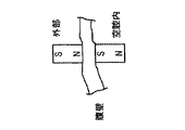
上述したものを幾つか含み、他の実施形態において、取付け機構には、磁石が含まれる。ロボットへの磁石の取付けは、多くの異なる方法で実施し得るが、その幾つかを図8A乃至8Cに示す。これには、腹壁に接触して置かれた患者の外部に磁石を含み得る。そして、この磁石は、ロボットと相互作用してロボットを支持し、そのロボットを所定の位置に保持する。外部磁石は、図8Aに示すように、患者の内側にあってロボットに取付けた高透磁率材料と相互作用し得る。その役割は、逆転することも可能であり、高透磁率材料を患者外部に置き、磁石を内部に置くこともできる。 In some embodiments, including some of those described above, the attachment mechanism includes a magnet. The attachment of the magnet to the robot can be performed in many different ways, some of which are shown in FIGS. 8A-8C. This may include a magnet outside the patient placed in contact with the abdominal wall. The magnet interacts with the robot to support the robot and holds the robot in place. The external magnet can interact with a high permeability material that is inside the patient and attached to the robot, as shown in FIG. 8A. The role can also be reversed, with high permeability materials placed outside the patient and magnets placed inside.
外部磁石は、患者の内側にあってロボットに取付けられた第2の磁石とも相互作用し得る。このことは、各磁石の単一の極を用いて(図8Bに示す)、又は各磁石の両極を用いる(図8Cに示す)ことによって、磁石の反対の極が引き合うようにすることができる。 The external magnet may also interact with a second magnet that is inside the patient and attached to the robot. This can be achieved by using the single pole of each magnet (shown in FIG. 8B) or by using both poles of each magnet (shown in FIG. 8C) to attract the opposite poles of the magnet. .
ロボットに関連する磁石(又は高透磁率材料)は、ロボットに取付ける必要すらない。ロボットを安定化する力を生成するような方法で相互作用するだけでよい(この安定性については後述する)。例えば、一枚の紙を磁石で冷蔵庫に取付ける場合に、磁石は紙に付かないが、冷蔵庫に紙を固定する力を生成する。同様な手法をロボットにも用いることができる。 The magnet (or high permeability material) associated with the robot does not need to be attached to the robot. It only needs to interact in such a way as to generate a force that stabilizes the robot (this stability will be discussed later). For example, when a piece of paper is attached to a refrigerator with a magnet, the magnet does not attach to the paper, but generates a force to fix the paper to the refrigerator. A similar technique can be used for robots.
上述した磁石取付けの方法は、多くの異なる組合せとして用い得る。例えば、任意の数の磁石(0,1,2,3,)をロボットの取付けのために用い得る。1つの明らかな手法は、ロボットの三角形の各コーナ部(又は各セグメント)に磁石を置き、三つ組の外部磁石を患者の外部で用いることである。しかしながら、三角形(又は他の開いた又は閉じた多角形(2辺以上))は、磁石の幾つかの異なる組合せによって支持されるのに特に良好に適合する。例えば、三角形の形状は、この単一の磁石によって付与された力に反応する多軸支持を提供することから、単一の磁石は、三角形の内側に用い得る。このことは、次の節で更に述べる。「V」配置構成又は他の多角形は、同様な支持を与えることができる。 The magnet attachment methods described above can be used in many different combinations. For example, any number of magnets (0, 1, 2, 3,) can be used for robot attachment. One obvious approach is to place a magnet in each corner (or segment) of the robot's triangle and use three sets of external magnets outside the patient. However, triangles (or other open or closed polygons (two or more sides)) are particularly well suited to be supported by several different combinations of magnets. For example, a single magnet can be used inside the triangle because the triangular shape provides multi-axis support that reacts to the force imparted by this single magnet. This is further described in the next section. A “V” arrangement or other polygons can provide similar support.
本明細書に開示する或る実施形態は、患者の身体内に配置された状態での様々な装置の実施形態の安定性を最大化することに関する。詳細に上述し且つ図9に示した生体内ロボット10の三角形配置構成について考える。これは、ロボットの可能な取付け方法の一つである。ここで、単一の磁石90が、患者の外にある磁石92に引きつけられるように、磁石90をロボット10に取付ける。ロボット上の磁石90は、ロボット10に上向きの力を生成する。
Certain embodiments disclosed herein relate to maximizing the stability of various device embodiments when placed within a patient's body. Consider the triangular arrangement of the in-
反力の簡易解釈を示す簡易化した自由体図(FBD)を図10に示す。ここで、磁石90は、ロボット10の(剛体であると仮定された)本体に上向きの力Fmを生成する。更に、ロボット10の重量Wは、図示したように、ロボット10の質量中心に作用している。ロボットの各コーナ部は、A,B,及びCと表記され、また、反力は、各コーナ部(FA,FB,FC)に示される。これらの反力は、ロボットの形状、腹壁の剛性、及び他の要因に応じて、各辺の長さに沿って任意の分布で生じ得る。しかしながら、説明を簡単にするために、これらの反力は、各コーナ部にまとめられるものと仮定する。最後に、手術中に処理される組織にロボット10が力を加える際のエンドエフェクタの力(FRH,FLH)を示す。更に、あらゆる外部付与モーメント又は動的負荷も考慮する必要がある。この解析は、更に詳細に後述するように、他のロボット配置構成(例えば、3つのマニピュレータを備えた正方形ロボット)に拡張することができる。
A simplified free body diagram (FBD) showing a simple interpretation of the reaction force is shown in FIG. Here, the
単一の磁石90によって生成された図10のロボット10の安定性は、様々な数学的な技法を用いて求め得る。そのような技法の一例については、パパドプロス(Papado
poulos_E)及びレイ(Rey_D)の、「可動マニピュレータ用の横転安定性マージンの新しい尺度(A_New_Measure_of_Tip-over_Stab
ility_Margin_for_Mobile_Manipulators)」、ロボティックス及び自動化に関するIEEE国際会議・議事録、ミネアポリス、ミネソタ州、1996年4月、(これは、大型オフロード車の安定性計算に関する)に記載されている。同様な技法を用いて、ロボット10の安定性を求めることもできる。この解析の簡易版は、ロボットの各接触線の周りの全ての外力(及びモーメント)からモーメントの和を得ることである。本例の第1ステップは、接触線ABの周りのモーメントの和を求めることである(図10)。得られたモーメントによって、(例えば、大きな磁石力に起因して)ロボットが腹壁に「押される」場合に、この配置構成は、安定であり、ロボットは落下しない。得られたモーメントによって、(例えば、小さい磁石力及び大きなロボット重量に起因して)ロボットが腹壁から「はがされる」場合に、ロボットは、不安定であり、腹壁から落下する。そして、これは、全ての接触線(本例では、BC及びCA)について繰り返して行う必要がある。
The stability of the
poulos_E) and Ray (Rey_D), “A new measure of rollover stability margin for mobile manipulators (A_New_Measure_of_Tip-over_Stab
(Ilty_Margin_for_Mobile_Manipulators) ”, IEEE International Conference and Minutes on Robotics and Automation, Minneapolis, Minnesota, April 1996 (this relates to large off-road vehicle stability calculations). A similar technique can be used to determine the stability of the
上記解析は、単一の磁石を用いてロボット10を所定の位置に保持できることを示す。
簡易例を図11に示す。ここで、ロボット10は、質量ゼロであると仮定され、そのエンドエフェクタで力が付与されていない。明らかに分かるように、大きな磁力FMは、線ABの周りにモーメントを生成し、このモーメントによって、ロボットが、腹壁内で回転し、従って、ロボットの安定した配置構成を形成する。同じことが、線BC及びCAについても当てはまる。
The above analysis shows that the
A simple example is shown in FIG. Here, the
図11のこの例は、更に、図12A及び12Bに示す2つの可能な配置構成によって例示される。この状況では、図12Aのロボット94は、上記図10に示す三角形配置構成の(A及びBに取付け磁石を備えた)1つのセグメントを単に用いることによって、生成し得る。図12Aでは、上腹壁(1つのセグメント)にロボット94を保持する2つの取付け点(A及びB)がある。ロボットのエンドエフェクタ(又はハンド)96が、任意の方向に力を付与する場合、ゼロではないモーメントが接触線ABの周りに存在する。これによって、ロボット94は、線ABの周りに回転し、また、何らかの不安定性が生じ得る。 This example of FIG. 11 is further illustrated by the two possible arrangements shown in FIGS. 12A and 12B. In this situation, the robot 94 of FIG. 12A can be generated by simply using one segment (with mounting magnets at A and B) of the triangular arrangement shown in FIG. 10 above. In FIG. 12A, there are two attachment points (A and B) holding the robot 94 on the upper abdominal wall (one segment). If the robot's end effector (or hand) 96 applies a force in any direction, there will be a non-zero moment around the contact line AB. This causes the robot 94 to rotate around the line AB and can cause some instability.
対照的に、図12は、点Cによって表される追加の構造を含む装置98を示す。本実施形態では、接触線ABの周りのモーメントを生成するハンド力(FHand)は、点Cにおける反力(FC)によって生成されたモーメントによって均衡し得る。同様に、他の接触線について考えた場合に(この場合BC及びAC、他の可能性については後述する)、モーメントが均衡され、安定した配置構成が生成される。再度、説明を簡素化するために、離散的な点(A,B,及びC)について述べるが、如何なる線セグメント(例えば、AB)も連続的な接触線であってよい。
In contrast, FIG. 12 shows a
1つの磁石に基づくこの安定性は、幾つかのロボットの配置構成として再現し得る。例えば、図13は、図11と同様な配置構成を示すが、図13の「三角形」は、「開いた」配置構成100であり、この場合、点Aは、2つの点(A及びA’)になる。この配置構成100も、全ての接触線(AB、BC、CA’、及びA’A)の周りのモーメントによってロボットが「はがされる」よりもむしろ腹壁に「押される」場合に、安定性を生成する。
This stability based on a single magnet can be reproduced as an arrangement of several robots. For example, FIG. 13 shows an arrangement similar to FIG. 11, but the “triangle” in FIG. 13 is an “open”
図14は、安定した取付けのために単一の磁石を用いる多辺多角形102の他の例を示す。上記で用いた同じ解析は、ここでも適用され、ロボット102が安定であることを示すために用い得る。更に、上述した配置構成で述べた単一の磁石によって提供される安定性は、多角形以外の形状の場合にも生じ得る。例えば、「V」又は「T」配置構成を用い
ることができる。これらの形状は、開いた又は閉じた状態であってよい。
FIG. 14 shows another example of a
単一の点で生じるロボット反力(例えば、FA,FB等、)の概念は、この議論の目的に対しては、過度の単純化であることが理解される。これらの力は、ロボットのあらゆる部分のあらゆるセグメントの連続体(又は離散的な点)として生じ得る。 It is understood that the concept of robot reaction forces (eg, F A , F B, etc.) occurring at a single point is oversimplification for the purposes of this discussion. These forces can occur as a continuum (or discrete point) of every segment of every part of the robot.
或る実施形態において、磁石「タイプ」の異なる組合せを用いることができる。例えば、ロボットは、ロボットの1つのコーナ部に磁石を有し、2つの高透磁率材料を他の2つのコーナ部(又は辺)に有することができる。又は、ロボットは、2つの磁石及び1つの高透磁率材料、又は他の組合せを有し得る。 In some embodiments, different combinations of magnet “types” may be used. For example, a robot can have a magnet in one corner of the robot and two high permeability materials in the other two corners (or sides). Or, the robot may have two magnets and one high permeability material, or other combination.
多数の実施形態を開示したが、本発明の例示の実施形態を示し記述する以下の詳細な説明から、本発明の更に他の実施形態が、当業者には明らかになるであろう。認識されるように、本発明は、様々な明白な態様の修正が、全て、本発明の精神及び範囲から逸脱することなく可能である。従って、図面及び詳細な説明は、本質的に例示であり限定的ではないものとする。 While numerous embodiments have been disclosed, still other embodiments of the present invention will become apparent to those skilled in the art from the following detailed description, which shows and describes illustrative embodiments of the invention. As will be realized, the invention is capable of modifications in various obvious aspects, all without departing from the spirit and scope of the invention. Accordingly, the drawings and detailed description are to be regarded as illustrative in nature and not as restrictive.
好適な実施形態を参照して、本発明について説明したが、当業者は、本発明の精神及び範囲から逸脱することなく、形態及び詳細について変更を行い得ることを認識されるであろう。 Although the present invention has been described with reference to preferred embodiments, workers skilled in the art will recognize that changes may be made in form and detail without departing from the spirit and scope of the invention.
Claims (20)
(a)患者の空腔内に配置されるように構成された第1の本体セグメントであって、
(i)第1の本体セグメントに関連付けられた第1の手術用コンポーネントと、
(ii)第1の本体セグメントの第1端部における第1の結合コンポーネントと、を含む、第1の本体セグメントと、
(b)前記患者の空腔内に配置されるように構成された第2の本体セグメントであって、
(i)第2の本体セグメントに関連付けられた第2の手術用コンポーネントと、
(ii)第2の本体セグメントの第1端部における第1の旋回連結器であって、第2の本体セグメントを第1の旋回連結器によって第1の本体セグメントに旋回可能に連結する、第1の旋回連結器と、
を含む、第2の本体セグメントと、
(c)前記患者の空腔内に配置されるように構成された第3の本体セグメントであって、
(i)第3の本体セグメントに関連付けられた第3の手術用コンポーネントと、
(ii)第3の本体セグメントの第1端部における第2の旋回連結器であって、第3の本体セグメントを第2の旋回連結器によって第2の本体セグメントに旋回可能に連結する、第2の旋回連結器と、
(iii)第3の本体セグメントの第2端部における第2の結合コンポーネントであって、第1の結合コンポーネントと連結可能なように構成された第2の結合コンポーネントと、
を含む、第3の本体セグメントと、
(d)前記セグメント化医療装置に関連付けられた取付けコンポーネントと、
から構成される、前記セグメント化医療装置。 In segmented medical devices, the system is
(A) a first body segment configured to be disposed within a patient's cavity,
(I) a first surgical component associated with the first body segment;
(Ii) a first body segment comprising: a first coupling component at a first end of the first body segment;
(B) a second body segment configured to be disposed within the patient's cavity,
(I) a second surgical component associated with the second body segment;
(Ii) a first swivel coupler at a first end of the second body segment, wherein the second body segment is pivotally coupled to the first body segment by the first swivel coupler; 1 swivel coupler;
A second body segment comprising:
(C) a third body segment configured to be disposed within the patient's cavity,
(I) a third surgical component associated with the third body segment;
(Ii) a second swivel coupler at a first end of the third body segment, wherein the third body segment is pivotally coupled to the second body segment by the second swivel coupler; Two swivel couplers;
(Iii) a second coupling component at a second end of the third body segment, the second coupling component configured to be connectable with the first coupling component;
A third body segment comprising:
(D) a mounting component associated with the segmented medical device;
The segmented medical device comprising:
(a)患者の空腔内に配置されるように構成された第1の本体セグメントであって、
(i)第1の本体セグメントに関連付けられた第1の手術用コンポーネントと、
(ii)第1の本体セグメントの第1端部における第1の結合コンポーネントと、を含む、第1の本体セグメントと、
(b)前記患者の空腔内に配置されるように構成された第2の本体セグメントであって、
(i)第2の本体セグメントに関連付けられた第2の手術用コンポーネントと、
(ii)第2の本体セグメントの第1端部における第1の旋回連結器であって、第2の本体セグメントを第1の旋回連結器によって第1の本体セグメントに旋回可能に連結する、前記第1の旋回連結器と、
を含む、第2の本体セグメントと、
(c)前記患者の空腔内に配置されるように構成された第3の本体セグメントであって、
(i)第3の本体セグメントに関連付けられた第3の手術用コンポーネントと、
(ii)第3の本体セグメントの第1端部における第2の旋回連結器であって、第3の本体セグメントを第2の旋回連結器によって第2の本体セグメントに旋回可能に連結する、前記第2の旋回連結器と、
(iii)第3の本体セグメントの第2端部における第2の結合コンポーネントであって、第1の結合コンポーネントと連結可能なように構成される、第2の結合コンポーネントと、
を含む、第3の本体セグメントと、
(d)前記セグメント化医療装置が、第1の及び第2の結合コンポーネントが連結されている閉じた配置構成にあるときに、実質的に中央位置に配置される取付けコンポーネントと、
から構成され、
前記セグメント化医療装置は、前記閉じた配置構成と、前記第1の及び第2の結合コンポーネントが共に連結されていない開いた配置構成と、の間で動くように構成されている、前記セグメント化医療装置。 In segmented medical devices, the system is
(A) a first body segment configured to be disposed within a patient's cavity,
(I) a first surgical component associated with the first body segment;
(Ii) a first body segment comprising: a first coupling component at a first end of the first body segment;
(B) a second body segment configured to be disposed within the patient's cavity,
(I) a second surgical component associated with the second body segment;
(Ii) a first swivel coupler at a first end of the second body segment, wherein the second body segment is pivotally coupled to the first body segment by the first swivel coupler; A first swivel coupler;
A second body segment comprising:
(C) a third body segment configured to be disposed within the patient's cavity,
(I) a third surgical component associated with the third body segment;
(Ii) a second swivel coupler at a first end of the third body segment, wherein the third body segment is pivotally coupled to the second body segment by the second swivel coupler; A second swivel coupler;
(Iii) a second coupling component at a second end of the third body segment, the second coupling component configured to be connectable with the first coupling component;
A third body segment comprising:
(D) an attachment component that is disposed in a substantially central position when the segmented medical device is in a closed configuration in which the first and second coupling components are coupled;
Consisting of
The segmented medical device is configured to move between the closed configuration and an open configuration in which the first and second coupling components are not coupled together. Medical device.
れ、該ロッドは、前記セグメント化医療装置から前記患者の空腔の外側に延びるように構成されている、請求項11に記載のセグメント化医療装置。 12. The attachment component includes a rod coupled to the segmented medical device, the rod configured to extend outside the patient cavity from the segmented medical device. The segmented medical device described.
(b)第2の本体セグメントには、第2外側円柱状コンポーネント内に配置された第2内側円柱状コンポーネントが含まれ、第2内側円柱状コンポーネントは、第2外側円柱状コンポーネントに対して回転可能であり、
(c)第3の本体セグメントには、第3外側円柱状コンポーネント内に配置された第3内側円柱状コンポーネントが含まれ、第3内側円柱状コンポーネントは、第3外側円柱状コンポーネントに対して回転可能である、請求項1に記載のセグメント化医療装置。 (A) The first body segment includes a first inner cylindrical component disposed within the first outer cylindrical component, the first inner cylindrical component rotating relative to the first outer cylindrical component. Is possible,
(B) the second body segment includes a second inner cylindrical component disposed within the second outer cylindrical component, the second inner cylindrical component rotating relative to the second outer cylindrical component; Is possible,
(C) the third body segment includes a third inner cylindrical component disposed within the third outer cylindrical component, the third inner cylindrical component rotating relative to the third outer cylindrical component; The segmented medical device of claim 1, which is possible.
(b)第2外側円柱状コンポーネントには、第2外側開口部が含まれ、第2内側円柱状コンポーネント及び第2外側円柱状コンポーネントは、第2の手術用コンポーネントが第2外側開口部を介してアクセス可能なように回転可能であり、
(c)第3内側円柱状コンポーネントには、第3内側開口部が含まれ、第3外側円柱状コンポーネントには、第3外側開口部が含まれ、第3内側円柱状コンポーネント及び第3外側円柱状コンポーネントは、第3内側開口部及び第3外側開口部が整列することによって前記第3内側円柱状コンポーネントの内側部分へのアクセスを提供するように回転可能である、請求項15に記載のセグメント化医療装置。 (A) The first inner cylindrical component includes a first inner opening, and the first outer cylindrical component includes a first outer opening, the first inner cylindrical component and the first outer circle. The columnar component is rotatable to provide access to the inner portion of the first inner cylindrical component by aligning the first inner opening and the first outer opening;
(B) The second outer cylindrical component includes a second outer opening, and the second inner cylindrical component and the second outer cylindrical component include the second surgical component via the second outer opening. And can be rotated for access
(C) The third inner cylindrical component includes a third inner opening, and the third outer cylindrical component includes a third outer opening, the third inner cylindrical component and the third outer circle. The segment of claim 15, wherein the columnar component is rotatable to provide access to the inner portion of the third inner cylindrical component by aligning the third inner opening and the third outer opening. Medical equipment.
(b)第3の手術用コンポーネントは、第3の手術用コンポーネントの一部が第3内側開口部及び第3外側開口部を介して、第3内側円柱状コンポーネントの内側部分内に配置された未展開位置と、第3内側円柱状コンポーネントの外に配置される展開位置と、の間で位置を変えるように構成されている、請求項16に記載のセグメント化医療装置。 (A) In the first surgical component, a part of the first surgical component is disposed in the inner portion of the first inner cylindrical component via the first inner opening and the first outer opening. Configured to change position between an undeployed position and a deployed position disposed outside the first inner cylindrical component;
(B) In the third surgical component, a part of the third surgical component is disposed in the inner portion of the third inner cylindrical component via the third inner opening and the third outer opening. The segmented medical device according to claim 16, configured to change position between an undeployed position and a deployed position disposed outside the third inner cylindrical component.
(a)患者の空腔内に配置されるように構成された第1の本体セグメントであって、
(i)第1の本体セグメントに関連付けられた第1の手術用コンポーネントと、
(ii)第1の本体セグメントの第1端部における第1の結合コンポーネントと、
を含む、第1の本体セグメントと、
(b)前記患者の空腔内に配置されるように構成された第2の本体セグメントであって、
(i)第2の本体セグメントに関連付けられた第2の手術用コンポーネントと、
(ii)第2の本体セグメントの第1端部における旋回連結器であって、第2の本体セグメントを旋回連結器によって第1の本体セグメントに旋回可能に連結する、旋回連結器と、
を含む、第2の本体セグメントと、
(c)前記患者の空腔内に配置されるように構成された第3の本体セグメントであって、
(i)第3の本体セグメントに関連付けられた第3の手術用コンポーネントと、
(ii)第3の本体セグメントの第1端部における旋回連結器であって、第3の本体セグメントを旋回連結器によって第2の本体セグメントに旋回可能に連結する、旋回連結器と、
を含む、第3の本体セグメントと、
(d)前記患者の空腔内に配置されるように構成された第4の本体セグメントであって、
(i)第4の本体セグメントに関連付けられた第4の手術用コンポーネントと、
(ii)第4の本体セグメントの第1端部における旋回連結器であって、第4の本体セグメントを旋回連結器によって第3の本体セグメントに旋回可能に連結する、旋回連結器と、
(iii)第4の本体セグメントの第2端部における第2の結合コンポーネントであって、第1の結合コンポーネントと連結可能なように構成される、第2の結合コンポーネントと、
を含む、第4の本体セグメントと、
(e)前記セグメント化医療装置が閉じた配置構成にあるときに、実質的に中央位置に配置される取付けコンポーネントと、
から構成される、セグメント化医療装置。 A segmented medical device,
(A) a first body segment configured to be disposed within a patient's cavity,
(I) a first surgical component associated with the first body segment;
(Ii) a first coupling component at a first end of the first body segment;
A first body segment comprising:
(B) a second body segment configured to be disposed within the patient's cavity,
(I) a second surgical component associated with the second body segment;
(Ii) a swivel coupler at the first end of the second body segment, wherein the swivel coupler pivotally couples the second body segment to the first body segment by the swivel coupler;
A second body segment comprising:
(C) a third body segment configured to be disposed within the patient's cavity,
(I) a third surgical component associated with the third body segment;
(Ii) a swivel coupler at the first end of the third body segment, wherein the swivel coupler pivotally couples the third body segment to the second body segment by the swivel coupler;
A third body segment comprising:
(D) a fourth body segment configured to be disposed within the patient's cavity,
(I) a fourth surgical component associated with the fourth body segment;
(Ii) a swivel coupler at the first end of the fourth body segment, wherein the swivel coupler pivotally couples the fourth body segment to the third body segment by the swivel coupler;
(Iii) a second coupling component at the second end of the fourth body segment, the second coupling component configured to be connectable with the first coupling component;
A fourth body segment comprising:
(E) an attachment component that is disposed in a substantially central position when the segmented medical device is in a closed configuration;
A segmented medical device composed of
Applications Claiming Priority (3)
| Application Number | Priority Date | Filing Date | Title |
|---|---|---|---|
| US28762809P | 2009-12-17 | 2009-12-17 | |
| US61/287,628 | 2009-12-17 | ||
| PCT/US2010/061137 WO2011075693A1 (en) | 2009-12-17 | 2010-12-17 | Modular and cooperative medical devices and related systems and methods |
Publications (1)
| Publication Number | Publication Date |
|---|---|
| JP2013514835A true JP2013514835A (en) | 2013-05-02 |
Family
ID=44167730
Family Applications (1)
| Application Number | Title | Priority Date | Filing Date |
|---|---|---|---|
| JP2012544922A Pending JP2013514835A (en) | 2009-12-17 | 2010-12-17 | Modular and collaborative medical devices and related systems and methods |
Country Status (5)
| Country | Link |
|---|---|
| US (1) | US8894633B2 (en) |
| EP (1) | EP2512754A4 (en) |
| JP (1) | JP2013514835A (en) |
| CA (1) | CA2784883A1 (en) |
| WO (1) | WO2011075693A1 (en) |
Families Citing this family (49)
| Publication number | Priority date | Publication date | Assignee | Title |
|---|---|---|---|---|
| US7960935B2 (en) | 2003-07-08 | 2011-06-14 | The Board Of Regents Of The University Of Nebraska | Robotic devices with agent delivery components and related methods |
| WO2007149559A2 (en) | 2006-06-22 | 2007-12-27 | Board Of Regents Of The University Of Nebraska | Magnetically coupleable robotic devices and related methods |
| US9579088B2 (en) | 2007-02-20 | 2017-02-28 | Board Of Regents Of The University Of Nebraska | Methods, systems, and devices for surgical visualization and device manipulation |
| US8974440B2 (en) | 2007-08-15 | 2015-03-10 | Board Of Regents Of The University Of Nebraska | Modular and cooperative medical devices and related systems and methods |
| US8679096B2 (en) | 2007-06-21 | 2014-03-25 | Board Of Regents Of The University Of Nebraska | Multifunctional operational component for robotic devices |
| EP3078344B1 (en) | 2007-07-12 | 2020-02-26 | Board of Regents of the University of Nebraska | Actuation in robotic devices |
| CA2695615A1 (en) | 2007-08-15 | 2009-02-19 | Board Of Regents Of The University Of Nebraska | Medical inflation, attachment, and delivery devices and related methods |
| US8888792B2 (en) | 2008-07-14 | 2014-11-18 | Ethicon Endo-Surgery, Inc. | Tissue apposition clip application devices and methods |
| US9138207B2 (en) | 2009-05-19 | 2015-09-22 | Teleflex Medical Incorporated | Methods and devices for laparoscopic surgery |
| JP2013514835A (en) | 2009-12-17 | 2013-05-02 | ボード オブ リージェンツ オブ ザ ユニバーシティ オブ ネブラスカ | Modular and collaborative medical devices and related systems and methods |
| US8721539B2 (en) | 2010-01-20 | 2014-05-13 | EON Surgical Ltd. | Rapid laparoscopy exchange system and method of use thereof |
| US10052088B2 (en) | 2010-01-20 | 2018-08-21 | EON Surgical Ltd. | System and method of deploying an elongate unit in a body cavity |
| EP2600758A1 (en) | 2010-08-06 | 2013-06-12 | Board of Regents of the University of Nebraska | Methods and systems for handling or delivering materials for natural orifice surgery |
| CN103220987B (en) | 2010-09-19 | 2016-05-18 | 意昂外科有限公司 | Micro Laparoscope and Its Improvement |
| CA2838637C (en) | 2011-06-10 | 2020-11-17 | Board Of Regents Of The University Of Nebraska | Methods, systems, and devices relating to surgical end effectors |
| JP6106169B2 (en) | 2011-07-11 | 2017-03-29 | ボード オブ リージェンツ オブ ザ ユニバーシティ オブ ネブラスカ | Surgical robot system |
| EP2882330B1 (en) * | 2011-10-03 | 2020-05-13 | Board of Regents of the University of Nebraska | Robotic surgical devices and systems |
| US10582973B2 (en) | 2012-08-08 | 2020-03-10 | Virtual Incision Corporation | Robotic surgical devices, systems, and related methods |
| EP3970784A1 (en) | 2012-01-10 | 2022-03-23 | Board of Regents of the University of Nebraska | Systems and devices for surgical access and insertion |
| US8891924B2 (en) | 2012-04-26 | 2014-11-18 | Bio-Medical Engineering (HK) Limited | Magnetic-anchored robotic system |
| US10179033B2 (en) | 2012-04-26 | 2019-01-15 | Bio-Medical Engineering (HK) Limited | Magnetic-anchored robotic system |
| CA2871149C (en) | 2012-05-01 | 2020-08-25 | Board Of Regents Of The University Of Nebraska | Single site robotic device and related systems and methods |
| US9427255B2 (en) | 2012-05-14 | 2016-08-30 | Ethicon Endo-Surgery, Inc. | Apparatus for introducing a steerable camera assembly into a patient |
| JP6228196B2 (en) | 2012-06-22 | 2017-11-08 | ボード オブ リージェンツ オブ ザ ユニバーシティ オブ ネブラスカ | Locally controlled robotic surgical device |
| ITFI20120132A1 (en) * | 2012-06-22 | 2013-12-23 | Scuola Superiore Di Studi Universit Ari E Di Perfe | DEVICE FOR ANCHORING ROBOTIC UNITS |
| US12295680B2 (en) | 2012-08-08 | 2025-05-13 | Board Of Regents Of The University Of Nebraska | Robotic surgical devices, systems and related methods |
| US9770305B2 (en) | 2012-08-08 | 2017-09-26 | Board Of Regents Of The University Of Nebraska | Robotic surgical devices, systems, and related methods |
| US10098527B2 (en) * | 2013-02-27 | 2018-10-16 | Ethidcon Endo-Surgery, Inc. | System for performing a minimally invasive surgical procedure |
| US9888966B2 (en) | 2013-03-14 | 2018-02-13 | Board Of Regents Of The University Of Nebraska | Methods, systems, and devices relating to force control surgical systems |
| US9743987B2 (en) | 2013-03-14 | 2017-08-29 | Board Of Regents Of The University Of Nebraska | Methods, systems, and devices relating to robotic surgical devices, end effectors, and controllers |
| CA2906772C (en) | 2013-03-15 | 2021-09-21 | Board Of Regents Of The University Of Nebraska | Robotic surgical devices, systems and related methods |
| CA2918531A1 (en) | 2013-07-17 | 2015-01-22 | Board Of Regents Of The University Of Nebraska | Robotic surgical devices, systems and related methods |
| CA3193139A1 (en) | 2014-05-05 | 2015-11-12 | Vicarious Surgical Inc. | Virtual reality surgical device |
| US10342561B2 (en) | 2014-09-12 | 2019-07-09 | Board Of Regents Of The University Of Nebraska | Quick-release end effectors and related systems and methods |
| WO2016077478A1 (en) | 2014-11-11 | 2016-05-19 | Board Of Regents Of The University Of Nebraska | Robotic device with compact joint design and related systems and methods |
| EP4555965A3 (en) | 2015-08-03 | 2025-07-02 | Virtual Incision Corporation | Robotic surgical devices, systems and related methods |
| JP7176757B2 (en) | 2016-05-18 | 2022-11-22 | バーチャル インシジョン コーポレイション | ROBOTIC SURGICAL DEVICES, SYSTEMS AND RELATED METHODS |
| WO2018039606A1 (en) | 2016-08-25 | 2018-03-01 | Virtual Incision Corporation | Quick-release tool coupler and related systems and methods |
| JP7090615B2 (en) | 2016-08-30 | 2022-06-24 | ボード オブ リージェンツ オブ ザ ユニバーシティ オブ ネブラスカ | Robot device |
| CN115337111B (en) | 2016-11-22 | 2025-04-25 | 内布拉斯加大学董事会 | Improved coarse positioning device and related system and method |
| CN110462259B (en) | 2016-11-29 | 2022-10-28 | 虚拟切割有限公司 | User controller with user presence detection and related systems and methods |
| US10722319B2 (en) | 2016-12-14 | 2020-07-28 | Virtual Incision Corporation | Releasable attachment device for coupling to medical devices and related systems and methods |
| WO2018148394A1 (en) | 2017-02-09 | 2018-08-16 | Vicarious Surgical Inc. | Virtual reality surgical tools system |
| CA3075692A1 (en) | 2017-09-14 | 2019-03-21 | Vicarious Surgical Inc. | Virtual reality surgical camera system |
| US11051894B2 (en) | 2017-09-27 | 2021-07-06 | Virtual Incision Corporation | Robotic surgical devices with tracking camera technology and related systems and methods |
| CN117140580A (en) | 2018-01-05 | 2023-12-01 | 内布拉斯加大学董事会 | Single-arm robotic device with compact joint design and related systems and methods |
| US11903658B2 (en) | 2019-01-07 | 2024-02-20 | Virtual Incision Corporation | Robotically assisted surgical system and related devices and methods |
| CN111166394B (en) * | 2020-02-12 | 2025-01-10 | 崇好科技有限公司 | An in vivo self-assembled magnetic anchoring device for laparoscopic cholecystectomy with reduced puncture |
| CA3186863A1 (en) | 2020-07-06 | 2022-01-13 | Virtual Incision Corporation | Surgical robot positioning system and related devices and methods |
Citations (2)
| Publication number | Priority date | Publication date | Assignee | Title |
|---|---|---|---|---|
| JP2007534350A (en) * | 2003-07-15 | 2007-11-29 | ザ・トラスティーズ・オブ・コロンビア・ユニバーシティ・イン・ザ・シティ・オブ・ニューヨーク | Insertable device and system for minimal access procedures |
| WO2009023851A1 (en) * | 2007-08-15 | 2009-02-19 | Board Of Regents Of The University Of Nebraska | Modular and cooperative medical devices and related systems and methods |
Family Cites Families (326)
| Publication number | Priority date | Publication date | Assignee | Title |
|---|---|---|---|---|
| US3870264A (en) * | 1973-03-26 | 1975-03-11 | William I Robinson | Stand |
| DE2339827B2 (en) | 1973-08-06 | 1977-02-24 | A6 In 3-02 | DENTAL EQUIPMENT |
| US4258716A (en) * | 1978-02-06 | 1981-03-31 | The University Of Melbourne | Microsurgical instruments |
| JPS5519124A (en) | 1978-07-27 | 1980-02-09 | Olympus Optical Co | Camera system for medical treatment |
| US4246661A (en) | 1979-03-15 | 1981-01-27 | The Boeing Company | Digitally-controlled artificial hand |
| JPS58132490A (en) * | 1982-01-29 | 1983-08-06 | 株式会社日立製作所 | Angle transmission mechanism |
| US5307447A (en) | 1982-10-29 | 1994-04-26 | Kabushiki Kaisha Toshiba | Control system of multi-joint arm robot apparatus |
| GB2130889B (en) | 1982-11-26 | 1986-06-18 | Wolf Gmbh Richard | Rectoscope |
| JPS6076986A (en) | 1983-09-30 | 1985-05-01 | 株式会社東芝 | Robot |
| DE3536747A1 (en) * | 1984-10-15 | 1986-04-24 | Tokico Ltd., Kawasaki, Kanagawa | Joint mechanism |
| DE3525806A1 (en) * | 1985-07-19 | 1987-01-29 | Kuka Schweissanlagen & Roboter | TRANSMISSION HEAD FOR MANIPULATORS |
| DE3545068A1 (en) | 1985-12-19 | 1987-06-25 | Kuka Schweissanlagen & Roboter | TRANSMISSION HEAD FOR MANIPULATORS |
| DE3612498A1 (en) | 1986-04-14 | 1987-10-29 | Norske Stats Oljeselskap | SELF-DRIVING VEHICLE FOR PIPELINES |
| JP2591968B2 (en) | 1987-12-28 | 1997-03-19 | 株式会社日立製作所 | Industrial robot wrist |
| US5187796A (en) * | 1988-03-29 | 1993-02-16 | Computer Motion, Inc. | Three-dimensional vector co-processor having I, J, and K register files and I, J, and K execution units |
| US5019968A (en) | 1988-03-29 | 1991-05-28 | Yulan Wang | Three-dimensional vector processor |
| US5108140A (en) | 1988-04-18 | 1992-04-28 | Odetics, Inc. | Reconfigurable end effector |
| US4896015A (en) * | 1988-07-29 | 1990-01-23 | Refractive Laser Research & Development Program, Ltd. | Laser delivery system |
| US4897014A (en) | 1988-09-06 | 1990-01-30 | Harbor Branch Oceanographic Institution, Inc. | Device for interchange of tools |
| US5271384A (en) | 1989-09-01 | 1993-12-21 | Mcewen James A | Powered surgical retractor |
| US5201325A (en) | 1989-09-01 | 1993-04-13 | Andronic Devices Ltd. | Advanced surgical retractor |
| US5562448A (en) | 1990-04-10 | 1996-10-08 | Mushabac; David R. | Method for facilitating dental diagnosis and treatment |
| JP2914388B2 (en) | 1990-04-17 | 1999-06-28 | 株式会社ユアサコーポレーション | Polymer solid electrolyte |
| IT1241622B (en) * | 1990-10-04 | 1994-01-25 | Comau Spa | ROBOT WRIST |
| IT1241621B (en) * | 1990-10-04 | 1994-01-25 | Comau Spa | ARTICULATED ROBOT |
| US5176649A (en) * | 1991-01-28 | 1993-01-05 | Akio Wakabayashi | Insertion device for use with curved, rigid endoscopic instruments and the like |
| US5217003A (en) | 1991-03-18 | 1993-06-08 | Wilk Peter J | Automated surgical system and apparatus |
| US5172639A (en) | 1991-03-26 | 1992-12-22 | Gas Research Institute | Cornering pipe traveler |
| US5370134A (en) | 1991-05-29 | 1994-12-06 | Orgin Medsystems, Inc. | Method and apparatus for body structure manipulation and dissection |
| US5632761A (en) | 1991-05-29 | 1997-05-27 | Origin Medsystems, Inc. | Inflatable devices for separating layers of tissue, and methods of using |
| US5417210A (en) | 1992-05-27 | 1995-05-23 | International Business Machines Corporation | System and method for augmentation of endoscopic surgery |
| US5284096A (en) * | 1991-08-06 | 1994-02-08 | Osaka Gas Company, Limited | Vehicle for use in pipes |
| US5674030A (en) | 1991-08-27 | 1997-10-07 | Sika Equipment Ag. | Device and method for repairing building branch lines in inacessible sewer mains |
| JP2526537B2 (en) | 1991-08-30 | 1996-08-21 | 日本電装株式会社 | Pipe energy supply system |
| US6731988B1 (en) | 1992-01-21 | 2004-05-04 | Sri International | System and method for remote endoscopic surgery |
| US5631973A (en) | 1994-05-05 | 1997-05-20 | Sri International | Method for telemanipulation with telepresence |
| JP3583777B2 (en) | 1992-01-21 | 2004-11-04 | エス・アール・アイ・インターナシヨナル | Teleoperator system and telepresence method |
| US5263382A (en) | 1992-04-13 | 1993-11-23 | Hughes Aircraft Company | Six Degrees of freedom motion device |
| US5297443A (en) * | 1992-07-07 | 1994-03-29 | Wentz John D | Flexible positioning appendage |
| US5762458A (en) | 1996-02-20 | 1998-06-09 | Computer Motion, Inc. | Method and apparatus for performing minimally invasive cardiac procedures |
| US5524180A (en) | 1992-08-10 | 1996-06-04 | Computer Motion, Inc. | Automated endoscope system for optimal positioning |
| US5657429A (en) | 1992-08-10 | 1997-08-12 | Computer Motion, Inc. | Automated endoscope system optimal positioning |
| US5515478A (en) | 1992-08-10 | 1996-05-07 | Computer Motion, Inc. | Automated endoscope system for optimal positioning |
| US7074179B2 (en) | 1992-08-10 | 2006-07-11 | Intuitive Surgical Inc | Method and apparatus for performing minimally invasive cardiac procedures |
| US5754741A (en) | 1992-08-10 | 1998-05-19 | Computer Motion, Inc. | Automated endoscope for optimal positioning |
| US5588442A (en) | 1992-08-12 | 1996-12-31 | Scimed Life Systems, Inc. | Shaft movement control apparatus and method |
| US5297536A (en) * | 1992-08-25 | 1994-03-29 | Wilk Peter J | Method for use in intra-abdominal surgery |
| US5458131A (en) | 1992-08-25 | 1995-10-17 | Wilk; Peter J. | Method for use in intra-abdominal surgery |
| US5769640A (en) | 1992-12-02 | 1998-06-23 | Cybernet Systems Corporation | Method and system for simulating medical procedures including virtual reality and control method and system for use therein |
| US5353807A (en) | 1992-12-07 | 1994-10-11 | Demarco Thomas J | Magnetically guidable intubation device |
| CA2112271A1 (en) | 1992-12-28 | 1994-06-29 | Kiichi Suyama | Intrapipe work robot apparatus and method of measuring position of intrapipe work robot |
| ATE203920T1 (en) | 1993-01-07 | 2001-08-15 | Medical Innovations Corp | CATHETER SYSTEM FOR GASTROSTOMY |
| US6832996B2 (en) | 1995-06-07 | 2004-12-21 | Arthrocare Corporation | Electrosurgical systems and methods for treating tissue |
| US5363935A (en) | 1993-05-14 | 1994-11-15 | Carnegie Mellon University | Reconfigurable mobile vehicle with magnetic tracks |
| US5791231A (en) | 1993-05-17 | 1998-08-11 | Endorobotics Corporation | Surgical robotic system and hydraulic actuator therefor |
| US5441494A (en) | 1993-07-29 | 1995-08-15 | Ethicon, Inc. | Manipulable hand for laparoscopy |
| US5382885A (en) * | 1993-08-09 | 1995-01-17 | The University Of British Columbia | Motion scaling tele-operating system with force feedback suitable for microsurgery |
| US5728599A (en) * | 1993-10-28 | 1998-03-17 | Lsi Logic Corporation | Printable superconductive leadframes for semiconductor device assembly |
| JP3476878B2 (en) | 1993-11-15 | 2003-12-10 | オリンパス株式会社 | Surgical manipulator |
| US5876325A (en) * | 1993-11-02 | 1999-03-02 | Olympus Optical Co., Ltd. | Surgical manipulation system |
| US5458598A (en) | 1993-12-02 | 1995-10-17 | Cabot Technology Corporation | Cutting and coagulating forceps |
| WO1995016396A1 (en) | 1993-12-15 | 1995-06-22 | Computer Motion, Inc. | Automated endoscope system for optimal positioning |
| US5471515A (en) | 1994-01-28 | 1995-11-28 | California Institute Of Technology | Active pixel sensor with intra-pixel charge transfer |
| US5436542A (en) | 1994-01-28 | 1995-07-25 | Surgix, Inc. | Telescopic camera mount with remotely controlled positioning |
| US5620417A (en) | 1994-07-07 | 1997-04-15 | Cardiovascular Imaging Systems Incorporated | Rapid exchange delivery catheter |
| US5623582A (en) | 1994-07-14 | 1997-04-22 | Immersion Human Interface Corporation | Computer interface or control input device for laparoscopic surgical instrument and other elongated mechanical objects |
| US7053752B2 (en) | 1996-08-06 | 2006-05-30 | Intuitive Surgical | General purpose distributed operating room control system |
| US6463361B1 (en) | 1994-09-22 | 2002-10-08 | Computer Motion, Inc. | Speech interface for an automated endoscopic system |
| US6646541B1 (en) | 1996-06-24 | 2003-11-11 | Computer Motion, Inc. | General purpose distributed operating room control system |
| US5653705A (en) | 1994-10-07 | 1997-08-05 | General Surgical Innovations, Inc. | Laparoscopic access port for surgical instruments or the hand |
| US6071274A (en) | 1996-12-19 | 2000-06-06 | Ep Technologies, Inc. | Loop structures for supporting multiple electrode elements |
| US5645520A (en) | 1994-10-12 | 1997-07-08 | Computer Motion, Inc. | Shape memory alloy actuated rod for endoscopic instruments |
| US5814062A (en) | 1994-12-22 | 1998-09-29 | Target Therapeutics, Inc. | Implant delivery assembly with expandable coupling/decoupling mechanism |
| GB2301187B (en) | 1995-05-22 | 1999-04-21 | British Gas Plc | Method of and apparatus for locating an anomaly in a duct |
| US5657584A (en) | 1995-07-24 | 1997-08-19 | Rensselaer Polytechnic Institute | Concentric joint mechanism |
| US6714841B1 (en) * | 1995-09-15 | 2004-03-30 | Computer Motion, Inc. | Head cursor control interface for an automated endoscope system for optimal positioning |
| US5825982A (en) | 1995-09-15 | 1998-10-20 | Wright; James | Head cursor control interface for an automated endoscope system for optimal positioning |
| US6283951B1 (en) * | 1996-10-11 | 2001-09-04 | Transvascular, Inc. | Systems and methods for delivering drugs to selected locations within the body |
| US5624398A (en) | 1996-02-08 | 1997-04-29 | Symbiosis Corporation | Endoscopic robotic surgical tools and methods |
| US5855583A (en) | 1996-02-20 | 1999-01-05 | Computer Motion, Inc. | Method and apparatus for performing minimally invasive cardiac procedures |
| US6699177B1 (en) * | 1996-02-20 | 2004-03-02 | Computer Motion, Inc. | Method and apparatus for performing minimally invasive surgical procedures |
| US6436107B1 (en) | 1996-02-20 | 2002-08-20 | Computer Motion, Inc. | Method and apparatus for performing minimally invasive surgical procedures |
| US5971976A (en) | 1996-02-20 | 1999-10-26 | Computer Motion, Inc. | Motion minimization and compensation system for use in surgical procedures |
| US6063095A (en) | 1996-02-20 | 2000-05-16 | Computer Motion, Inc. | Method and apparatus for performing minimally invasive surgical procedures |
| US5895417A (en) | 1996-03-06 | 1999-04-20 | Cardiac Pathways Corporation | Deflectable loop design for a linear lesion ablation apparatus |
| US5797900A (en) | 1996-05-20 | 1998-08-25 | Intuitive Surgical, Inc. | Wrist mechanism for surgical instrument for performing minimally invasive surgery with enhanced dexterity and sensitivity |
| US6544276B1 (en) | 1996-05-20 | 2003-04-08 | Medtronic Ave. Inc. | Exchange method for emboli containment |
| US5807377A (en) | 1996-05-20 | 1998-09-15 | Intuitive Surgical, Inc. | Force-reflecting surgical instrument and positioning mechanism for performing minimally invasive surgery with enhanced dexterity and sensitivity |
| US5792135A (en) * | 1996-05-20 | 1998-08-11 | Intuitive Surgical, Inc. | Articulated surgical instrument for performing minimally invasive surgery with enhanced dexterity and sensitivity |
| US6652480B1 (en) | 1997-03-06 | 2003-11-25 | Medtronic Ave., Inc. | Methods for reducing distal embolization |
| US6911916B1 (en) | 1996-06-24 | 2005-06-28 | The Cleveland Clinic Foundation | Method and apparatus for accessing medical data over a network |
| US6496099B2 (en) | 1996-06-24 | 2002-12-17 | Computer Motion, Inc. | General purpose distributed operating room control system |
| US6642836B1 (en) | 1996-08-06 | 2003-11-04 | Computer Motion, Inc. | General purpose distributed operating room control system |
| US6364888B1 (en) | 1996-09-09 | 2002-04-02 | Intuitive Surgical, Inc. | Alignment of master and slave in a minimally invasive surgical apparatus |
| US6520951B1 (en) * | 1996-09-13 | 2003-02-18 | Scimed Life Systems, Inc. | Rapid exchange catheter with detachable hood |
| IT1285533B1 (en) | 1996-10-22 | 1998-06-08 | Scuola Superiore Di Studi Universitari E Di Perfezionamento Sant Anna | ENDOSCOPIC ROBOT |
| US6293282B1 (en) | 1996-11-05 | 2001-09-25 | Jerome Lemelson | System and method for treating select tissue in living being |
| US6286514B1 (en) | 1996-11-05 | 2001-09-11 | Jerome Lemelson | System and method for treating select tissue in a living being |
| US5845646A (en) | 1996-11-05 | 1998-12-08 | Lemelson; Jerome | System and method for treating select tissue in a living being |
| US6058323A (en) | 1996-11-05 | 2000-05-02 | Lemelson; Jerome | System and method for treating select tissue in a living being |
| US6132441A (en) | 1996-11-22 | 2000-10-17 | Computer Motion, Inc. | Rigidly-linked articulating wrist with decoupled motion transmission |
| US6132368A (en) | 1996-12-12 | 2000-10-17 | Intuitive Surgical, Inc. | Multi-component telepresence system and method |
| US6331181B1 (en) | 1998-12-08 | 2001-12-18 | Intuitive Surgical, Inc. | Surgical robotic tools, data architecture, and use |
| US6332880B1 (en) | 1996-12-19 | 2001-12-25 | Ep Technologies, Inc. | Loop structures for supporting multiple electrode elements |
| US6066090A (en) | 1997-06-19 | 2000-05-23 | Yoon; Inbae | Branched endoscope system |
| US6714839B2 (en) * | 1998-12-08 | 2004-03-30 | Intuitive Surgical, Inc. | Master having redundant degrees of freedom |
| JP3342021B2 (en) | 1997-10-17 | 2002-11-05 | サーコン コーポレーション | Medical device system that penetrates tissue |
| US6240312B1 (en) | 1997-10-23 | 2001-05-29 | Robert R. Alfano | Remote-controllable, micro-scale device for use in in vivo medical diagnosis and/or treatment |
| FR2771280B1 (en) | 1997-11-26 | 2001-01-26 | Albert P Alby | RESILIENT VERTEBRAL CONNECTION DEVICE |
| US7169141B2 (en) * | 1998-02-24 | 2007-01-30 | Hansen Medical, Inc. | Surgical instrument |
| US6692485B1 (en) * | 1998-02-24 | 2004-02-17 | Endovia Medical, Inc. | Articulated apparatus for telemanipulator system |
| US20020095175A1 (en) | 1998-02-24 | 2002-07-18 | Brock David L. | Flexible instrument |
| US7090683B2 (en) | 1998-02-24 | 2006-08-15 | Hansen Medical, Inc. | Flexible instrument |
| US6810281B2 (en) | 2000-12-21 | 2004-10-26 | Endovia Medical, Inc. | Medical mapping system |
| US6309403B1 (en) | 1998-06-01 | 2001-10-30 | Board Of Trustees Operating Michigan State University | Dexterous articulated linkage for surgical applications |
| US6030365A (en) * | 1998-06-10 | 2000-02-29 | Laufer; Michael D. | Minimally invasive sterile surgical access device and method |
| US6352503B1 (en) * | 1998-07-17 | 2002-03-05 | Olympus Optical Co., Ltd. | Endoscopic surgery apparatus |
| US6246200B1 (en) | 1998-08-04 | 2001-06-12 | Intuitive Surgical, Inc. | Manipulator positioning linkage for robotic surgery |
| US6468265B1 (en) | 1998-11-20 | 2002-10-22 | Intuitive Surgical, Inc. | Performing cardiac surgery without cardioplegia |
| US6554790B1 (en) | 1998-11-20 | 2003-04-29 | Intuitive Surgical, Inc. | Cardiopulmonary bypass device and method |
| US6852107B2 (en) * | 2002-01-16 | 2005-02-08 | Computer Motion, Inc. | Minimally invasive surgical training using robotics and tele-collaboration |
| US6951535B2 (en) | 2002-01-16 | 2005-10-04 | Intuitive Surgical, Inc. | Tele-medicine system that transmits an entire state of a subsystem |
| US6659939B2 (en) * | 1998-11-20 | 2003-12-09 | Intuitive Surgical, Inc. | Cooperative minimally invasive telesurgical system |
| US6398726B1 (en) | 1998-11-20 | 2002-06-04 | Intuitive Surgical, Inc. | Stabilizer for robotic beating-heart surgery |
| US6459926B1 (en) | 1998-11-20 | 2002-10-01 | Intuitive Surgical, Inc. | Repositioning and reorientation of master/slave relationship in minimally invasive telesurgery |
| US6162171A (en) | 1998-12-07 | 2000-12-19 | Wan Sing Ng | Robotic endoscope and an autonomous pipe robot for performing endoscopic procedures |
| US6493608B1 (en) | 1999-04-07 | 2002-12-10 | Intuitive Surgical, Inc. | Aspects of a control system of a minimally invasive surgical apparatus |
| US6522906B1 (en) * | 1998-12-08 | 2003-02-18 | Intuitive Surgical, Inc. | Devices and methods for presenting and regulating auxiliary information on an image display of a telesurgical system to assist an operator in performing a surgical procedure |
| US6620173B2 (en) | 1998-12-08 | 2003-09-16 | Intuitive Surgical, Inc. | Method for introducing an end effector to a surgical site in minimally invasive surgery |
| US7125403B2 (en) | 1998-12-08 | 2006-10-24 | Intuitive Surgical | In vivo accessories for minimally invasive robotic surgery |
| US6720988B1 (en) | 1998-12-08 | 2004-04-13 | Intuitive Surgical, Inc. | Stereo imaging system and method for use in telerobotic systems |
| US6799065B1 (en) | 1998-12-08 | 2004-09-28 | Intuitive Surgical, Inc. | Image shifting apparatus and method for a telerobotic system |
| USD444555S1 (en) | 1998-12-08 | 2001-07-03 | Intuitive Surgical, Inc. | Interface for a medical instrument |
| USD441076S1 (en) | 1998-12-08 | 2001-04-24 | Intuitive Surgical, Inc. | Adaptor for a medical instrument |
| USD441862S1 (en) | 1998-12-08 | 2001-05-08 | Intuitive Surgical, Inc. | Portion of an interface for a medical instrument |
| USD438617S1 (en) * | 1998-12-08 | 2001-03-06 | Intuitive Surgical, Inc. | Portion of an adaptor for a medical instrument |
| US6770081B1 (en) | 2000-01-07 | 2004-08-03 | Intuitive Surgical, Inc. | In vivo accessories for minimally invasive robotic surgery and methods |
| US6309397B1 (en) | 1999-12-02 | 2001-10-30 | Sri International | Accessories for minimally invasive robotic surgery and methods |
| US6451027B1 (en) | 1998-12-16 | 2002-09-17 | Intuitive Surgical, Inc. | Devices and methods for moving an image capture device in telesurgical systems |
| US6394998B1 (en) | 1999-01-22 | 2002-05-28 | Intuitive Surgical, Inc. | Surgical tools for use in minimally invasive telesurgical applications |
| US8636648B2 (en) * | 1999-03-01 | 2014-01-28 | West View Research, Llc | Endoscopic smart probe |
| US6159146A (en) | 1999-03-12 | 2000-12-12 | El Gazayerli; Mohamed Mounir | Method and apparatus for minimally-invasive fundoplication |
| US6594552B1 (en) | 1999-04-07 | 2003-07-15 | Intuitive Surgical, Inc. | Grip strength with tactile feedback for robotic surgery |
| US6424885B1 (en) | 1999-04-07 | 2002-07-23 | Intuitive Surgical, Inc. | Camera referenced control in a minimally invasive surgical apparatus |
| US6565554B1 (en) | 1999-04-07 | 2003-05-20 | Intuitive Surgical, Inc. | Friction compensation in a minimally invasive surgical apparatus |
| US6820653B1 (en) | 1999-04-12 | 2004-11-23 | Carnegie Mellon University | Pipe inspection and repair system |
| US6292678B1 (en) | 1999-05-13 | 2001-09-18 | Stereotaxis, Inc. | Method of magnetically navigating medical devices with magnetic fields and gradients, and medical devices adapted therefor |
| US7637905B2 (en) | 2003-01-15 | 2009-12-29 | Usgi Medical, Inc. | Endoluminal tool deployment system |
| US6788018B1 (en) | 1999-08-03 | 2004-09-07 | Intuitive Surgical, Inc. | Ceiling and floor mounted surgical robot set-up arms |
| US6454775B1 (en) | 1999-12-06 | 2002-09-24 | Bacchus Vascular Inc. | Systems and methods for clot disruption and retrieval |
| US6661571B1 (en) | 1999-09-21 | 2003-12-09 | Olympus Optical Co., Ltd. | Surgical microscopic system |
| US6936001B1 (en) | 1999-10-01 | 2005-08-30 | Computer Motion, Inc. | Heart stabilizer |
| US6817972B2 (en) | 1999-10-01 | 2004-11-16 | Computer Motion, Inc. | Heart stabilizer |
| US7217240B2 (en) | 1999-10-01 | 2007-05-15 | Intuitive Surgical, Inc. | Heart stabilizer |
| US6206903B1 (en) * | 1999-10-08 | 2001-03-27 | Intuitive Surgical, Inc. | Surgical tool with mechanical advantage |
| US6491691B1 (en) | 1999-10-08 | 2002-12-10 | Intuitive Surgical, Inc. | Minimally invasive surgical hook apparatus and method for using same |
| US6312435B1 (en) | 1999-10-08 | 2001-11-06 | Intuitive Surgical, Inc. | Surgical instrument with extended reach for use in minimally invasive surgery |
| JP3326472B2 (en) | 1999-11-10 | 2002-09-24 | 独立行政法人 航空宇宙技術研究所 | Articulated robot |
| US6702805B1 (en) | 1999-11-12 | 2004-03-09 | Microdexterity Systems, Inc. | Manipulator |
| US6548982B1 (en) | 1999-11-19 | 2003-04-15 | Regents Of The University Of Minnesota | Miniature robotic vehicles and methods of controlling same |
| US6591239B1 (en) | 1999-12-09 | 2003-07-08 | Steris Inc. | Voice controlled surgical suite |
| US6817975B1 (en) | 2000-01-14 | 2004-11-16 | Intuitive Surgical, Inc. | Endoscope |
| US7039453B2 (en) | 2000-02-08 | 2006-05-02 | Tarun Mullick | Miniature ingestible capsule |
| AU2001249308A1 (en) | 2000-03-24 | 2001-10-15 | Johns Hopkins University | Peritoneal cavity device and method |
| US6837846B2 (en) * | 2000-04-03 | 2005-01-04 | Neo Guide Systems, Inc. | Endoscope having a guide tube |
| US6468203B2 (en) | 2000-04-03 | 2002-10-22 | Neoguide Systems, Inc. | Steerable endoscope and improved method of insertion |
| US6610007B2 (en) | 2000-04-03 | 2003-08-26 | Neoguide Systems, Inc. | Steerable segmented endoscope and method of insertion |
| US6974411B2 (en) | 2000-04-03 | 2005-12-13 | Neoguide Systems, Inc. | Endoscope with single step guiding apparatus |
| US6984203B2 (en) * | 2000-04-03 | 2006-01-10 | Neoguide Systems, Inc. | Endoscope with adjacently positioned guiding apparatus |
| US6508413B2 (en) * | 2000-04-06 | 2003-01-21 | Siemens Westinghouse Power Corporation | Remote spray coating of nuclear cross-under piping |
| US6450104B1 (en) | 2000-04-28 | 2002-09-17 | North Carolina State University | Modular observation crawler and sensing instrument and method for operating same |
| US6645196B1 (en) | 2000-06-16 | 2003-11-11 | Intuitive Surgical, Inc. | Guided tool change |
| FR2812067B1 (en) | 2000-07-18 | 2003-05-16 | Commissariat Energie Atomique | MOBILE ROBOT ABLE TO WORK IN PIPES OR OTHER NARROW PASSAGES |
| US6746443B1 (en) * | 2000-07-27 | 2004-06-08 | Intuitive Surgical Inc. | Roll-pitch-roll surgical tool |
| US6902560B1 (en) | 2000-07-27 | 2005-06-07 | Intuitive Surgical, Inc. | Roll-pitch-roll surgical tool |
| US6726699B1 (en) | 2000-08-15 | 2004-04-27 | Computer Motion, Inc. | Instrument guide |
| US6860877B1 (en) * | 2000-09-29 | 2005-03-01 | Computer Motion, Inc. | Heart stabilizer support arm |
| US6475215B1 (en) | 2000-10-12 | 2002-11-05 | Naim Erturk Tanrisever | Quantum energy surgical device and method |
| WO2002041787A2 (en) | 2000-11-27 | 2002-05-30 | Tyco Healthcare Group Lp | Tissue sampling and removal apparatus and method |
| EP2269500B1 (en) | 2000-11-28 | 2017-06-21 | Intuitive Surgical Operations, Inc. | Endoscopic beating-heart stabilizer and vessel occlusion fastener |
| JP4655175B2 (en) | 2000-12-19 | 2011-03-23 | ソニー株式会社 | MANIPULATOR SYSTEM, MASTER MANIPULATOR, SLAVE MANIPULATOR, CONTROL METHOD THEREOF, AND RECORDING MEDIUM |
| US6840938B1 (en) * | 2000-12-29 | 2005-01-11 | Intuitive Surgical, Inc. | Bipolar cauterizing instrument |
| US6934589B2 (en) | 2000-12-29 | 2005-08-23 | Medtronic, Inc. | System and method for placing endocardial leads |
| US7519421B2 (en) | 2001-01-16 | 2009-04-14 | Kenergy, Inc. | Vagal nerve stimulation using vascular implanted devices for treatment of atrial fibrillation |
| KR100380181B1 (en) * | 2001-02-10 | 2003-04-11 | 한국과학기술연구원 | Micro Robot for Test the Large Intestines |
| US6871563B2 (en) * | 2001-02-26 | 2005-03-29 | Howie Choset | Orientation preserving angular swivel joint |
| ATE301264T1 (en) | 2001-03-07 | 2005-08-15 | Univ Carnegie Mellon | ROBOT SYSTEM FOR INSPECTING GAS PIPES |
| US6870343B2 (en) * | 2001-03-30 | 2005-03-22 | The University Of Michigan | Integrated, proportionally controlled, and naturally compliant universal joint actuator with controllable stiffness |
| US6774597B1 (en) | 2001-03-30 | 2004-08-10 | The Regents Of The University Of Michigan | Apparatus for obstacle traversion |
| US6512345B2 (en) * | 2001-03-30 | 2003-01-28 | The Regents Of The University Of Michigan | Apparatus for obstacle traversion |
| WO2002082979A2 (en) | 2001-04-18 | 2002-10-24 | Bbms Ltd. | Navigating and maneuvering of an in vivo vechicle by extracorporeal devices |
| US6994708B2 (en) * | 2001-04-19 | 2006-02-07 | Intuitive Surgical | Robotic tool with monopolar electro-surgical scissors |
| US6783524B2 (en) | 2001-04-19 | 2004-08-31 | Intuitive Surgical, Inc. | Robotic surgical tool with ultrasound cauterizing and cutting instrument |
| KR100413058B1 (en) | 2001-04-24 | 2003-12-31 | 한국과학기술연구원 | Micro Robotic Colonoscope with Motor Locomotion |
| US6687571B1 (en) * | 2001-04-24 | 2004-02-03 | Sandia Corporation | Cooperating mobile robots |
| KR100426613B1 (en) | 2001-05-19 | 2004-04-08 | 한국과학기술연구원 | Micro robot driving system |
| KR100402920B1 (en) | 2001-05-19 | 2003-10-22 | 한국과학기술연구원 | Micro robot |
| US9226699B2 (en) | 2002-04-19 | 2016-01-05 | Sanofi-Aventis Deutschland Gmbh | Body fluid sampling module with a continuous compression tissue interface surface |
| US6817974B2 (en) | 2001-06-29 | 2004-11-16 | Intuitive Surgical, Inc. | Surgical tool having positively positionable tendon-actuated multi-disk wrist joint |
| CA2451824C (en) | 2001-06-29 | 2015-02-24 | Intuitive Surgical, Inc. | Platform link wrist mechanism |
| US20040243147A1 (en) | 2001-07-03 | 2004-12-02 | Lipow Kenneth I. | Surgical robot and robotic controller |
| US20050083460A1 (en) | 2001-07-16 | 2005-04-21 | Nippon Sheet Glass Co., Ltd. | Semi-transmitting mirror-possessing substrate, and semi-transmitting type liquid crystal display apparatus |
| JP4744026B2 (en) * | 2001-07-30 | 2011-08-10 | オリンパス株式会社 | Capsule endoscope and capsule endoscope system |
| US6676684B1 (en) * | 2001-09-04 | 2004-01-13 | Intuitive Surgical, Inc. | Roll-pitch-roll-yaw surgical tool |
| US6728599B2 (en) | 2001-09-07 | 2004-04-27 | Computer Motion, Inc. | Modularity system for computer assisted surgery |
| US6764441B2 (en) | 2001-09-17 | 2004-07-20 | Case Western Reserve University | Peristaltically self-propelled endoscopic device |
| US6587750B2 (en) | 2001-09-25 | 2003-07-01 | Intuitive Surgical, Inc. | Removable infinite roll master grip handle and touch sensor for robotic surgery |
| WO2003028542A2 (en) | 2001-10-02 | 2003-04-10 | Arthrocare Corporation | Apparatus and methods for electrosurgical removal and digestion of tissue |
| US6835173B2 (en) | 2001-10-05 | 2004-12-28 | Scimed Life Systems, Inc. | Robotic endoscope |
| US7182025B2 (en) * | 2001-10-17 | 2007-02-27 | William Marsh Rice University | Autonomous robotic crawler for in-pipe inspection |
| AU2002356817A1 (en) | 2001-10-17 | 2003-04-28 | William Marsh Rice University | Autonomous robotic crawler for in-pipe inspection |
| US6730021B2 (en) | 2001-11-07 | 2004-05-04 | Computer Motion, Inc. | Tissue spreader with force measurement, force indication or force limitation |
| KR100417163B1 (en) | 2001-11-12 | 2004-02-05 | 한국과학기술연구원 | Micro capsule robot |
| US7294146B2 (en) | 2001-12-03 | 2007-11-13 | Xtent, Inc. | Apparatus and methods for delivery of variable length stents |
| US6839612B2 (en) * | 2001-12-07 | 2005-01-04 | Institute Surgical, Inc. | Microwrist system for surgical procedures |
| US6793653B2 (en) | 2001-12-08 | 2004-09-21 | Computer Motion, Inc. | Multifunctional handle for a medical robotic system |
| US20030114731A1 (en) | 2001-12-14 | 2003-06-19 | Cadeddu Jeffrey A. | Magnetic positioning system for trocarless laparoscopic instruments |
| US6780191B2 (en) | 2001-12-28 | 2004-08-24 | Yacmur Llc | Cannula system |
| US6676660B2 (en) | 2002-01-23 | 2004-01-13 | Ethicon Endo-Surgery, Inc. | Feedback light apparatus and method for use with an electrosurgical instrument |
| US7967816B2 (en) | 2002-01-25 | 2011-06-28 | Medtronic, Inc. | Fluid-assisted electrosurgical instrument with shapeable electrode |
| AU2003218050A1 (en) | 2002-02-11 | 2003-09-04 | Arthrocare Corporation | Electrosurgical apparatus and methods for laparoscopy |
| ATE333066T1 (en) | 2002-03-05 | 2006-08-15 | Wagner Wilhelm Wiwa | DEVICE AND METHOD FOR INNER COATING OF A PIPE |
| US7831292B2 (en) | 2002-03-06 | 2010-11-09 | Mako Surgical Corp. | Guidance system and method for surgical procedures with improved feedback |
| WO2003077101A2 (en) * | 2002-03-06 | 2003-09-18 | Z-Kat, Inc. | System and method for using a haptic device in combination with a computer-assisted surgery system |
| US20030179308A1 (en) | 2002-03-19 | 2003-09-25 | Lucia Zamorano | Augmented tracking using video, computed data and/or sensing technologies |
| JP3869291B2 (en) | 2002-03-25 | 2007-01-17 | オリンパス株式会社 | Capsule medical device |
| JP3917885B2 (en) | 2002-04-08 | 2007-05-23 | オリンパス株式会社 | Capsule endoscope system |
| US6860346B2 (en) * | 2002-04-19 | 2005-03-01 | Regents Of The University Of Minnesota | Adjustable diameter wheel assembly, and methods and vehicles using same |
| US20030230372A1 (en) | 2002-06-13 | 2003-12-18 | Kurt Schmidt | Method for placing objects on the inner wall of a placed sewer pipe and device for carrying out said method |
| US6801325B2 (en) | 2002-06-25 | 2004-10-05 | Intuitive Surgical, Inc. | Method and devices for inspecting and calibrating of stereoscopic endoscopes |
| US6776165B2 (en) * | 2002-09-12 | 2004-08-17 | The Regents Of The University Of California | Magnetic navigation system for diagnosis, biopsy and drug delivery vehicles |
| JP4133188B2 (en) | 2002-10-07 | 2008-08-13 | 株式会社ハーモニック・ドライブ・システムズ | Robot hand finger unit |
| US7794494B2 (en) | 2002-10-11 | 2010-09-14 | Boston Scientific Scimed, Inc. | Implantable medical devices |
| JP3700848B2 (en) | 2002-10-23 | 2005-09-28 | Necエンジニアリング株式会社 | Micro light source position measuring device |
| US6936003B2 (en) | 2002-10-29 | 2005-08-30 | Given Imaging Ltd | In-vivo extendable element device and system, and method of use |
| JP4148763B2 (en) | 2002-11-29 | 2008-09-10 | 学校法人慈恵大学 | Endoscopic surgery robot |
| JP3686947B2 (en) | 2002-12-09 | 2005-08-24 | 国立大学法人 東京大学 | High-rigid forceps tip structure for active forceps and active forceps including the same |
| WO2004071284A1 (en) * | 2003-02-11 | 2004-08-26 | Olympus Corporation | Overtube, producing method and placing method of the same, and method of treating intra-abdominal cavity |
| US7083615B2 (en) | 2003-02-24 | 2006-08-01 | Intuitive Surgical Inc | Surgical tool having electrocautery energy supply conductor with inhibited current leakage |
| US7105000B2 (en) | 2003-03-25 | 2006-09-12 | Ethicon Endo-Surgery, Inc. | Surgical jaw assembly with increased mechanical advantage |
| JP3752494B2 (en) * | 2003-03-31 | 2006-03-08 | 株式会社東芝 | Master-slave manipulator, control device and control method thereof |
| JP4329394B2 (en) | 2003-04-30 | 2009-09-09 | 株式会社島津製作所 | Small photographing device |
| DE10323216B3 (en) | 2003-05-22 | 2004-12-23 | Siemens Ag | Endoscope apparatus has cameras which are provided at respective ends of endoscope capsule, such that one of camera is tilted or rotated to change photography range |
| US7121781B2 (en) | 2003-06-11 | 2006-10-17 | Intuitive Surgical | Surgical instrument with a universal wrist |
| JP4532188B2 (en) | 2003-06-30 | 2010-08-25 | カール−ツアイス−スチフツング | Holding device, in particular for medical optical instruments, with means for compensating the load rotational moment |
| GB0315479D0 (en) | 2003-07-02 | 2003-08-06 | Paz Adrian | Virtual ports devices |
| US7042184B2 (en) * | 2003-07-08 | 2006-05-09 | Board Of Regents Of The University Of Nebraska | Microrobot for surgical applications |
| US7126303B2 (en) | 2003-07-08 | 2006-10-24 | Board Of Regents Of The University Of Nebraska | Robot for surgical applications |
| US20080058989A1 (en) * | 2006-04-13 | 2008-03-06 | Board Of Regents Of The University Of Nebraska | Surgical camera robot |
| US7960935B2 (en) | 2003-07-08 | 2011-06-14 | The Board Of Regents Of The University Of Nebraska | Robotic devices with agent delivery components and related methods |
| WO2009058350A1 (en) | 2007-11-02 | 2009-05-07 | The Trustees Of Columbia University In The City Of New York | Insertable surgical imaging device |
| US20100081875A1 (en) | 2003-07-15 | 2010-04-01 | EndoRobotics Inc. | Surgical Device For Minimal Access Surgery |
| JP2005074031A (en) | 2003-09-01 | 2005-03-24 | Pentax Corp | Capsule endoscope |
| JP4128505B2 (en) | 2003-09-05 | 2008-07-30 | オリンパス株式会社 | Capsule endoscope |
| JP4128504B2 (en) | 2003-09-05 | 2008-07-30 | オリンパス株式会社 | Capsule endoscope |
| US7993384B2 (en) * | 2003-09-12 | 2011-08-09 | Abbott Cardiovascular Systems Inc. | Delivery system for medical devices |
| DE10343494B4 (en) * | 2003-09-19 | 2006-06-14 | Siemens Ag | Magnetically navigable device for use in the field of medical endoscopy |
| US7594815B2 (en) * | 2003-09-24 | 2009-09-29 | Toly Christopher C | Laparoscopic and endoscopic trainer including a digital camera |
| US7789825B2 (en) | 2003-09-29 | 2010-09-07 | Ethicon Endo-Surgery, Inc. | Handle for endoscopic device |
| US20050096502A1 (en) | 2003-10-29 | 2005-05-05 | Khalili Theodore M. | Robotic surgical device |
| US7147650B2 (en) | 2003-10-30 | 2006-12-12 | Woojin Lee | Surgical instrument |
| US8162925B2 (en) | 2003-11-07 | 2012-04-24 | Carnegie Mellon University | Robot for minimally invasive interventions |
| US7429259B2 (en) | 2003-12-02 | 2008-09-30 | Cadeddu Jeffrey A | Surgical anchor and system |
| US7625338B2 (en) | 2003-12-31 | 2009-12-01 | Given Imaging, Ltd. | In-vivo sensing device with alterable fields of view |
| US7566300B2 (en) | 2004-04-15 | 2009-07-28 | Wilson-Cook Medical, Inc. | Endoscopic surgical access devices and methods of articulating an external accessory channel |
| US20070244520A1 (en) | 2004-04-19 | 2007-10-18 | Searete Llc | Lumen-traveling biological interface device and method of use |
| US7998060B2 (en) | 2004-04-19 | 2011-08-16 | The Invention Science Fund I, Llc | Lumen-traveling delivery device |
| US7857767B2 (en) | 2004-04-19 | 2010-12-28 | Invention Science Fund I, Llc | Lumen-traveling device |
| US8512219B2 (en) * | 2004-04-19 | 2013-08-20 | The Invention Science Fund I, Llc | Bioelectromagnetic interface system |
| JP2008505666A (en) | 2004-06-24 | 2008-02-28 | エル. ギルデンバーグ,フィリップ | Semi-automatic suturing device |
| US7892230B2 (en) | 2004-06-24 | 2011-02-22 | Arthrocare Corporation | Electrosurgical device having planar vertical electrode and related methods |
| US20050288555A1 (en) | 2004-06-28 | 2005-12-29 | Binmoeller Kenneth E | Methods and devices for illuminating, vievwing and monitoring a body cavity |
| US9968290B2 (en) | 2004-06-30 | 2018-05-15 | Given Imaging Ltd. | Apparatus and methods for capsule endoscopy of the esophagus |
| US20060046226A1 (en) * | 2004-08-27 | 2006-03-02 | Bergler Hans J | Dental imaging system and method of use |
| US20090012422A1 (en) | 2004-11-08 | 2009-01-08 | Eduardo Marban | Bioptome |
| US8128680B2 (en) | 2005-01-10 | 2012-03-06 | Taheri Laduca Llc | Apparatus and method for deploying an implantable device within the body |
| US20060152591A1 (en) | 2005-01-13 | 2006-07-13 | Sheng-Feng Lin | Automatic focus mechanism of an image capturing device |
| US7763015B2 (en) | 2005-01-24 | 2010-07-27 | Intuitive Surgical Operations, Inc. | Modular manipulator support for robotic surgery |
| US20060241570A1 (en) | 2005-04-22 | 2006-10-26 | Wilk Patent, Llc | Intra-abdominal medical method |
| US7785251B2 (en) | 2005-04-22 | 2010-08-31 | Wilk Patent, Llc | Port extraction method for trans-organ surgery |
| US7762960B2 (en) | 2005-05-13 | 2010-07-27 | Boston Scientific Scimed, Inc. | Biopsy forceps assemblies |
| US7708687B2 (en) | 2005-05-27 | 2010-05-04 | Bern M Jonathan | Endoscope propulsion system and method |
| US20070123748A1 (en) | 2005-07-14 | 2007-05-31 | Dwight Meglan | Robot for minimally invasive interventions |
| US20070106113A1 (en) | 2005-11-07 | 2007-05-10 | Biagio Ravo | Combination endoscopic operative delivery system |
| US7761137B2 (en) | 2005-12-16 | 2010-07-20 | Suros Surgical Systems, Inc. | Biopsy site marker deployment device |
| US7762825B2 (en) | 2005-12-20 | 2010-07-27 | Intuitive Surgical Operations, Inc. | Electro-mechanical interfaces to mount robotic surgical arms |
| US7930065B2 (en) | 2005-12-30 | 2011-04-19 | Intuitive Surgical Operations, Inc. | Robotic surgery system including position sensors using fiber bragg gratings |
| US7785333B2 (en) | 2006-02-21 | 2010-08-31 | Olympus Medical Systems Corp. | Overtube and operative procedure via bodily orifice |
| EP1815949A1 (en) | 2006-02-03 | 2007-08-08 | The European Atomic Energy Community (EURATOM), represented by the European Commission | Medical robotic system with manipulator arm of the cylindrical coordinate type |
| US20060253109A1 (en) | 2006-02-08 | 2006-11-09 | David Chu | Surgical robotic helping hand system |
| WO2007111571A1 (en) | 2006-03-27 | 2007-10-04 | Nanyang Technological University | Surgical robotic system for flexible endoscopy |
| US8585733B2 (en) | 2006-04-19 | 2013-11-19 | Vibrynt, Inc | Devices, tools and methods for performing minimally invasive abdominal surgical procedures |
| US7862573B2 (en) | 2006-04-21 | 2011-01-04 | Darois Roger E | Method and apparatus for surgical fastening |
| US7731727B2 (en) | 2006-04-26 | 2010-06-08 | Lsi Solutions, Inc. | Medical instrument to place a pursestring suture, open a hole and pass a guidewire |
| JP2009535161A (en) | 2006-04-29 | 2009-10-01 | ボード・オブ・リージエンツ,ザ・ユニバーシテイ・オブ・テキサス・システム | Device for use in transmural and intraluminal surgery |
| US8679096B2 (en) | 2007-06-21 | 2014-03-25 | Board Of Regents Of The University Of Nebraska | Multifunctional operational component for robotic devices |
| WO2007149559A2 (en) * | 2006-06-22 | 2007-12-27 | Board Of Regents Of The University Of Nebraska | Magnetically coupleable robotic devices and related methods |
| US9579088B2 (en) | 2007-02-20 | 2017-02-28 | Board Of Regents Of The University Of Nebraska | Methods, systems, and devices for surgical visualization and device manipulation |
| US9585714B2 (en) | 2006-07-13 | 2017-03-07 | Bovie Medical Corporation | Surgical sealing and cutting apparatus |
| US8551114B2 (en) | 2006-11-06 | 2013-10-08 | Human Robotics S.A. De C.V. | Robotic surgical device |
| WO2008076194A2 (en) | 2006-11-13 | 2008-06-26 | Raytheon Sarcos Llc | Serpentine robotic crawler |
| US7935130B2 (en) | 2006-11-16 | 2011-05-03 | Intuitive Surgical Operations, Inc. | Two-piece end-effectors for robotic surgical tools |
| US7655004B2 (en) * | 2007-02-15 | 2010-02-02 | Ethicon Endo-Surgery, Inc. | Electroporation ablation apparatus, system, and method |
| US8591399B2 (en) | 2007-04-25 | 2013-11-26 | Karl Storz Endovision, Inc. | Surgical method utilizing transluminal endoscope and instruments |
| DE102007031957A1 (en) * | 2007-07-10 | 2009-01-22 | Pierburg Gmbh | Combined non-return and control valve |
| EP3078344B1 (en) * | 2007-07-12 | 2020-02-26 | Board of Regents of the University of Nebraska | Actuation in robotic devices |
| CA2695615A1 (en) * | 2007-08-15 | 2009-02-19 | Board Of Regents Of The University Of Nebraska | Medical inflation, attachment, and delivery devices and related methods |
| WO2009114613A2 (en) | 2008-03-11 | 2009-09-17 | Health Research Inc. | System and method for robotic surgery simulation |
| US8020741B2 (en) | 2008-03-18 | 2011-09-20 | Barosense, Inc. | Endoscopic stapling devices and methods |
| US8328802B2 (en) | 2008-03-19 | 2012-12-11 | Covidien Ag | Cordless medical cauterization and cutting device |
| US8641663B2 (en) | 2008-03-27 | 2014-02-04 | St. Jude Medical, Atrial Fibrillation Division, Inc. | Robotic catheter system input device |
| US8727966B2 (en) | 2008-03-31 | 2014-05-20 | Intuitive Surgical Operations, Inc. | Endoscope with rotationally deployed arms |
| WO2009144729A1 (en) | 2008-05-28 | 2009-12-03 | Technion Research & Development Foundation Ltd. | Laparoscopic camera array |
| US20100010294A1 (en) * | 2008-07-10 | 2010-01-14 | Ethicon Endo-Surgery, Inc. | Temporarily positionable medical devices |
| JP5559785B2 (en) * | 2008-07-18 | 2014-07-23 | ボストン サイエンティフィック サイムド,インコーポレイテッド | Guided endoscope |
| WO2010022088A1 (en) * | 2008-08-18 | 2010-02-25 | Encision, Inc. | Enhanced control systems including flexible shielding and support systems for electrosurgical applications |
| US20100069710A1 (en) * | 2008-09-02 | 2010-03-18 | Ken Yamatani | treatment method |
| US8834353B2 (en) * | 2008-09-02 | 2014-09-16 | Olympus Medical Systems Corp. | Medical manipulator, treatment system, and treatment method |
| JP5115425B2 (en) | 2008-09-24 | 2013-01-09 | 豊田合成株式会社 | Group III nitride semiconductor light emitting device |
| US20110230894A1 (en) | 2008-10-07 | 2011-09-22 | The Trustees Of Columbia University In The City Of New York | Systems, devices, and methods for providing insertable robotic sensory and manipulation platforms for single port surgery |
| ITFI20080201A1 (en) | 2008-10-20 | 2010-04-21 | Scuola Superiore Di Studi Universit Ari E Di Perfe | ENDOLUMINAL ROBOTIC SYSTEM |
| EP2286756B1 (en) | 2009-08-21 | 2013-04-03 | Novineon Healthcare Technology Partners Gmbh | Surgical manipulator means |
| JP2013514835A (en) | 2009-12-17 | 2013-05-02 | ボード オブ リージェンツ オブ ザ ユニバーシティ オブ ネブラスカ | Modular and collaborative medical devices and related systems and methods |
| IT1399603B1 (en) | 2010-04-26 | 2013-04-26 | Scuola Superiore Di Studi Universitari E Di Perfez | ROBOTIC SYSTEM FOR MINIMUM INVASIVE SURGERY INTERVENTIONS |
| EP2600758A1 (en) * | 2010-08-06 | 2013-06-12 | Board of Regents of the University of Nebraska | Methods and systems for handling or delivering materials for natural orifice surgery |
| CA2838637C (en) | 2011-06-10 | 2020-11-17 | Board Of Regents Of The University Of Nebraska | Methods, systems, and devices relating to surgical end effectors |
-
2010
- 2010-12-17 JP JP2012544922A patent/JP2013514835A/en active Pending
- 2010-12-17 US US12/971,917 patent/US8894633B2/en not_active Expired - Fee Related
- 2010-12-17 CA CA2784883A patent/CA2784883A1/en not_active Abandoned
- 2010-12-17 EP EP10838323.3A patent/EP2512754A4/en not_active Withdrawn
- 2010-12-17 WO PCT/US2010/061137 patent/WO2011075693A1/en not_active Ceased
Patent Citations (2)
| Publication number | Priority date | Publication date | Assignee | Title |
|---|---|---|---|---|
| JP2007534350A (en) * | 2003-07-15 | 2007-11-29 | ザ・トラスティーズ・オブ・コロンビア・ユニバーシティ・イン・ザ・シティ・オブ・ニューヨーク | Insertable device and system for minimal access procedures |
| WO2009023851A1 (en) * | 2007-08-15 | 2009-02-19 | Board Of Regents Of The University Of Nebraska | Modular and cooperative medical devices and related systems and methods |
Also Published As
| Publication number | Publication date |
|---|---|
| CA2784883A1 (en) | 2011-06-23 |
| EP2512754A1 (en) | 2012-10-24 |
| EP2512754A4 (en) | 2016-11-30 |
| WO2011075693A1 (en) | 2011-06-23 |
| US20110237890A1 (en) | 2011-09-29 |
| US8894633B2 (en) | 2014-11-25 |
Similar Documents
| Publication | Publication Date | Title |
|---|---|---|
| JP2013514835A (en) | Modular and collaborative medical devices and related systems and methods | |
| JP5475662B2 (en) | Modular and segmented medical devices and related systems | |
| US20240414046A1 (en) | Robotic surgical devices, systems, and related methods | |
| US9579163B2 (en) | Robotic platform for mini-invasive surgery | |
| CN102149339B (en) | Tool for minimally invasive surgery and method for using the same | |
| US10219871B2 (en) | Robotic system for tele-surgery | |
| CN103237504B (en) | Minimally Invasive Surgery apparatus | |
| CN102458295B (en) | Robotic system for laparoscopic surgery | |
| CN108013906A (en) | Snakelike operating theater instruments | |
| US11832911B2 (en) | Surgical platform supported by multiple arms | |
| Lim et al. | Design and comparison of magnetically-actuated dexterous forceps instruments for neuroendoscopy | |
| US11844584B2 (en) | Robotic system for tele-surgery | |
| Patronik et al. | Crawling on the heart: A mobile robotic device for minimally invasive cardiac interventions | |
| CN112826592B (en) | End effector and minimally invasive surgical instrument |
Legal Events
| Date | Code | Title | Description |
|---|---|---|---|
| A621 | Written request for application examination |
Free format text: JAPANESE INTERMEDIATE CODE: A621 Effective date: 20131213 |
|
| A977 | Report on retrieval |
Free format text: JAPANESE INTERMEDIATE CODE: A971007 Effective date: 20140822 |
|
| A131 | Notification of reasons for refusal |
Free format text: JAPANESE INTERMEDIATE CODE: A131 Effective date: 20140909 |
|
| A02 | Decision of refusal |
Free format text: JAPANESE INTERMEDIATE CODE: A02 Effective date: 20150224 |