CN108732155B - Raman probe - Google Patents
Raman probe Download PDFInfo
- Publication number
- CN108732155B CN108732155B CN201710278434.1A CN201710278434A CN108732155B CN 108732155 B CN108732155 B CN 108732155B CN 201710278434 A CN201710278434 A CN 201710278434A CN 108732155 B CN108732155 B CN 108732155B
- Authority
- CN
- China
- Prior art keywords
- lens
- raman
- quarter
- wave plate
- camera
- Prior art date
- Legal status (The legal status is an assumption and is not a legal conclusion. Google has not performed a legal analysis and makes no representation as to the accuracy of the status listed.)
- Active
Links
- 238000001069 Raman spectroscopy Methods 0.000 title claims abstract description 35
- 239000000523 sample Substances 0.000 title claims abstract description 29
- 230000010287 polarization Effects 0.000 claims abstract description 14
- 230000008878 coupling Effects 0.000 claims abstract description 7
- 238000010168 coupling process Methods 0.000 claims abstract description 7
- 238000005859 coupling reaction Methods 0.000 claims abstract description 7
- 239000013307 optical fiber Substances 0.000 claims abstract description 4
- 238000003384 imaging method Methods 0.000 claims description 4
- 238000000034 method Methods 0.000 claims description 3
- 239000000835 fiber Substances 0.000 abstract description 10
- 230000003287 optical effect Effects 0.000 abstract description 9
- 238000001237 Raman spectrum Methods 0.000 abstract description 6
- 238000001514 detection method Methods 0.000 description 14
- 238000005286 illumination Methods 0.000 description 13
- 230000005540 biological transmission Effects 0.000 description 3
- 230000002238 attenuated effect Effects 0.000 description 2
- 238000006555 catalytic reaction Methods 0.000 description 1
- 238000012512 characterization method Methods 0.000 description 1
- 238000010586 diagram Methods 0.000 description 1
- 239000000463 material Substances 0.000 description 1
- 230000004048 modification Effects 0.000 description 1
- 238000012986 modification Methods 0.000 description 1
- 230000008569 process Effects 0.000 description 1
- 239000004065 semiconductor Substances 0.000 description 1
- 239000007787 solid Substances 0.000 description 1
- 230000003595 spectral effect Effects 0.000 description 1
- 238000004611 spectroscopical analysis Methods 0.000 description 1
- 238000010183 spectrum analysis Methods 0.000 description 1
- 230000009466 transformation Effects 0.000 description 1
- 238000000844 transformation Methods 0.000 description 1
Images

Classifications
-
- G—PHYSICS
- G01—MEASURING; TESTING
- G01N—INVESTIGATING OR ANALYSING MATERIALS BY DETERMINING THEIR CHEMICAL OR PHYSICAL PROPERTIES
- G01N21/00—Investigating or analysing materials by the use of optical means, i.e. using sub-millimetre waves, infrared, visible or ultraviolet light
- G01N21/62—Systems in which the material investigated is excited whereby it emits light or causes a change in wavelength of the incident light
- G01N21/63—Systems in which the material investigated is excited whereby it emits light or causes a change in wavelength of the incident light optically excited
- G01N21/65—Raman scattering
Landscapes
- Health & Medical Sciences (AREA)
- Nuclear Medicine, Radiotherapy & Molecular Imaging (AREA)
- Physics & Mathematics (AREA)
- Life Sciences & Earth Sciences (AREA)
- Chemical & Material Sciences (AREA)
- Analytical Chemistry (AREA)
- Biochemistry (AREA)
- General Health & Medical Sciences (AREA)
- General Physics & Mathematics (AREA)
- Immunology (AREA)
- Pathology (AREA)
- Investigating, Analyzing Materials By Fluorescence Or Luminescence (AREA)
Abstract
本发明提供了一种拉曼探头,包括:依序设置的激光输入光纤,准直透镜,窄带滤光片,二向色镜,聚焦透镜,反射镜,高通滤光片,耦合透镜和拉曼信号输出光纤;窄带滤光片和二向色镜之间依次设有线偏振器,偏振分光棱镜和四分之一波片;线偏振器的通光轴与四分之一波片的快轴呈45°角;偏振分光棱镜的垂直光路上依序设有会聚透镜和摄像头。本发明能够实现视场拍照定位,在探测样品拉曼光谱的同时探测样品的所处位置。
The invention provides a Raman probe, comprising: a laser input fiber arranged in sequence, a collimator lens, a narrow-band filter, a dichroic mirror, a focusing lens, a reflection mirror, a high-pass filter, a coupling lens and a Raman Signal output optical fiber; a linear polarizer, a polarization beam splitter and a quarter-wave plate are sequentially arranged between the narrow-band filter and the dichroic mirror; the light pass axis of the linear polarizer is aligned with the fast axis of the quarter-wave plate 45° angle; the vertical optical path of the polarization beam splitter prism is sequentially provided with a converging lens and a camera. The invention can realize the photographing and positioning of the field of view, and detect the position of the sample while detecting the Raman spectrum of the sample.
Description
技术领域technical field
本发明涉及光谱分析技术领域,具体涉及一种应用于便携式拉曼光谱仪的拉曼探头。The invention relates to the technical field of spectral analysis, in particular to a Raman probe applied to a portable Raman spectrometer.
背景技术Background technique
显微拉曼光谱仪是一种重要的光谱分析设备。目前因被广泛应用于固体物理、半导体物理、催化、表面、生物化学、材料表征和宝石鉴定等领域。显微拉曼光谱仪主要由拉曼探头和显微镜组成。在显微镜的视场范围内,激光聚焦在视场内的待测样品的某个位置上,激发出拉曼光谱。因此显微拉曼光谱仪不仅能够探测样品的拉曼光谱,还能够通过显微镜成像确定探测点位于显微镜视场中的哪个位置。然而在便携式拉曼光谱仪中,为了降低仪器成本,往往无法配置显微镜。因此,如何开发出一种新型的应用于便携式拉曼光谱仪上的拉曼探头,能够在拉曼探头中集成微型摄像头,实现视场拍照定位。令无法配置显微镜的便携式拉曼光谱仪与显微拉曼光谱仪一样,兼备探测样品拉曼光谱和探测样品位置的功能。Micro Raman spectrometer is an important spectroscopic analysis equipment. At present, it is widely used in the fields of solid state physics, semiconductor physics, catalysis, surface, biochemistry, material characterization and gem identification. A micro-Raman spectrometer is mainly composed of a Raman probe and a microscope. Within the field of view of the microscope, the laser is focused on a certain position of the sample to be tested within the field of view to excite the Raman spectrum. Therefore, the micro-Raman spectrometer can not only detect the Raman spectrum of the sample, but also determine where the detection point is located in the field of view of the microscope through microscope imaging. However, in portable Raman spectrometers, in order to reduce the cost of the instrument, it is often impossible to configure a microscope. Therefore, how to develop a new type of Raman probe applied to a portable Raman spectrometer, which can integrate a micro camera in the Raman probe to realize the positioning of the field of view. The portable Raman spectrometer that cannot be configured with a microscope has the same functions as a micro-Raman spectrometer to detect the Raman spectrum of the sample and the position of the sample.
发明内容Contents of the invention
本发明提供了一种拉曼探头,无需配备显微镜实现在探测样品拉曼光谱的同时探测样品的所处位置。The invention provides a Raman probe, which can detect the position of the sample while detecting the Raman spectrum of the sample without being equipped with a microscope.
其采用的技术方案如下:The technical scheme adopted is as follows:
一种拉曼探头,包括:依序设置的激光输入光纤,准直透镜,窄带滤光片,二向色镜,聚焦透镜,反射镜,高通滤光片,耦合透镜和拉曼信号输出光纤;所述窄带滤光片和二向色镜之间依次设有线偏振器,偏振分光棱镜和四分之一波片;所述线偏振器的通光轴与四分之一波片的快轴/慢轴呈45°角;所述偏振分光棱镜的垂直光路上依序设有会聚透镜和摄像头。A Raman probe, comprising: a laser input fiber, a collimator lens, a narrow-band filter, a dichroic mirror, a focusing lens, a reflector, a high-pass filter, a coupling lens and a Raman signal output fiber arranged in sequence; A linear polarizer, a polarization beam splitter and a quarter-wave plate are sequentially arranged between the narrow-band filter and the dichroic mirror; the optical axis of the linear polarizer is connected to the fast axis/ The slow axis is at an angle of 45°; a converging lens and a camera are sequentially arranged on the vertical optical path of the polarization beam splitter prism.
采用这种技术方案:激光输入光纤输出的检测激光经线偏振器后形成线偏振光。该线偏振光从偏振棱镜透射后达到四分之一波片,因线偏振器的通光轴与四分之一波片6的快轴或慢轴呈45°角,该线偏振光在经过四分之一波片后成为圆偏振光。然后经过二向色镜反射,由聚焦透镜会聚到待测样品上激发出拉曼信号。此时。激发出的拉曼信号经过聚焦透镜准直后,从二向色镜透射后入射到反射镜,然后由高通滤光片滤除杂散光后经耦合透镜耦合到拉曼信号输出光纤12。同时,聚焦透镜会聚待测样品上存在的激光散射光作为聚焦透镜的视场区域照明光波。该照明光波经过聚焦透镜准直后,被二向色镜反射后入射到四分之一波片6。此时该照明光波经四分之一波片后变为线偏振光,且其线偏振方向与检测激光在线偏振器处产生的线偏振方向互相垂直。因此该照明光波在达到偏振棱镜时被偏振棱镜反射。随后经过会聚透镜入射到摄像头,对聚焦透镜的视场区域成像,从而实现具有视场拍照定位的拉曼探头。This technical solution is adopted: the detection laser light output by the laser input fiber passes through the linear polarizer to form linear polarized light. The linearly polarized light reaches the quarter-wave plate after being transmitted from the polarizing prism, because the light-passing axis of the linear polarizer and the fast axis or slow axis of the quarter-wave plate 6 are at an angle of 45°, the linearly polarized light passes through After a quarter wave plate, it becomes circularly polarized light. Then it is reflected by the dichroic mirror, and then converged to the sample to be measured by the focusing lens to excite the Raman signal. at this time. After the excited Raman signal is collimated by the focusing lens, it is transmitted from the dichroic mirror and then enters the reflector, and then the stray light is filtered by the high-pass filter, and then coupled to the Raman
优选的是,上述拉曼探头中:还包括衰减片,所述衰减片设于之间偏振分光棱镜与会聚透镜之间。Preferably, the above-mentioned Raman probe: further includes an attenuation sheet, and the attenuation sheet is arranged between the polarizing beam splitter prism and the converging lens.
采用这种技术方案:通过设置衰减片,将由偏振分光棱镜反射向会聚透镜的照明光波进行衰减,避免因为该照明光波太强而导致摄像头饱和。This technical solution is adopted: by setting the attenuation sheet, the illumination light wave reflected by the polarization beam splitter prism to the converging lens is attenuated, so as to avoid saturation of the camera because the illumination light wave is too strong.
更优选的是,上述拉曼探头中:所述摄像头可采用带自动调焦成像镜头的摄像头。More preferably, in the above-mentioned Raman probe: the camera can be a camera with an auto-focusing imaging lens.
与现有技术相比,本发明结构简单,易于制备。具备视场拍照定位功能,能够在探测样品拉曼光谱的同时定位样品所处位置。Compared with the prior art, the invention has a simple structure and is easy to prepare. It has the function of taking pictures and positioning the field of view, and can locate the position of the sample while detecting the Raman spectrum of the sample.
附图说明Description of drawings
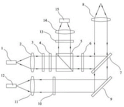
图1为本发明实施例1的结构示意图。Fig. 1 is a schematic structural diagram of Embodiment 1 of the present invention.
各附图标记与部件名称对应关系如下:The corresponding relationship between each reference sign and the part name is as follows:
1、激光输入光纤;2、准直透镜;3、窄带滤光片;4、线偏振器;5、偏振分光棱镜;6、四分之一波片;7、二向色镜;8、聚焦透镜;9、反射镜;10、高通滤光片;11、耦合透镜;12、拉曼信号输出光纤;13、衰减片;14、会聚透镜;15、摄像头。1. Laser input fiber; 2. Collimating lens; 3. Narrowband filter; 4. Linear polarizer; 5. Polarizing beam splitter; 6. Quarter wave plate; 7. Dichroic mirror; 8. Focusing Lens; 9. Mirror; 10. High-pass filter; 11. Coupling lens; 12. Raman signal output fiber; 13. Attenuation sheet; 14. Converging lens; 15. Camera.
具体实施方式Detailed ways
为了更清楚地说明本发明的技术方案,下面将结合附图对本发明作进一步描述。In order to illustrate the technical solution of the present invention more clearly, the present invention will be further described below in conjunction with the accompanying drawings.
如图1所示为本发明的实施例1:As shown in Figure 1 is embodiment 1 of the present invention:
一种拉曼探头,包括:依序设置的激光输入光纤1,准直透镜2,窄带滤光片3,二向色镜7,聚焦透镜8,反射镜9,高通滤光片10,耦合透镜11和拉曼信号输出光纤12。其中,所述窄带滤光片3和二向色镜7之间依次设有线偏振器4,偏振分光棱镜5和四分之一波片6;所述线偏振器4的通光轴与四分之一波片6的快轴呈45°角;所述偏振分光棱镜5的垂直光路上依序设有衰减片13,会聚透镜14和带自动调焦成像镜头的摄像头15。A Raman probe, comprising: a laser input fiber 1 arranged in sequence, a collimating lens 2, a narrow-band filter 3, a dichroic mirror 7, a focusing lens 8, a reflector 9, a high-
实践中,其工作过程如下:In practice, the working process is as follows:
激光输入光纤1输出检测激光,该检测激光经过准直透镜2后成为平行光,该平行光为非偏振激光。该检测激光经窄带率光片3限制波谱宽度。在经过线偏振器4后成为线偏振检测激光。该线偏振检测激光从偏振分光棱镜5透射后到达四分之一波片6;经四分之一波片6后成为圆偏振检测激光。然后该圆偏振检测激光经二向色镜7反射,由聚焦透镜8会聚到待测样品上,激发出拉曼信号。此时同步产生了两个传输光路:第一个传输光路是被激发出的拉曼信号经过聚焦透镜8准直后,从二向色镜7透射后入射到反射镜9,然后通过高通滤光片10滤除激光等杂散光,最后经过耦合透镜11耦合到拉曼信号输出光纤12上。第二个传输光路是由聚焦镜8会聚待测样品上存在的检测激光的散射光,将该检测激光的散射光作为聚焦镜8视场区域的照明光波。该照明光波经过聚焦镜8准直后,其光波偏振态仍然主要为圆偏振照明光波,被二向色镜7反射后入射到四分之一波片6。此时圆偏振照明光波经过四分之一波片6后变为线偏振照明光波,且该线偏振照明光波的偏振方向与检测激光在经过线偏振器4时产生的线偏振检测激光方向互相垂直。因此该线偏振照明光波被偏振棱镜5反射进入垂直光路。随后经过衰减片13衰减和会聚镜14会聚后入射到摄像头15上对聚焦镜8的视场区域成像,从而实现具有视场拍照定位的拉曼探头。The laser input optical fiber 1 outputs detection laser light, and the detection laser light becomes parallel light after passing through the collimating lens 2, and the parallel light is non-polarized laser light. The detection laser passes through the narrow-band rate optical sheet 3 to limit the spectral width. After passing through the linear polarizer 4, it becomes a linearly polarized detection laser. The linearly polarized detection laser light is transmitted through the polarization beam splitter prism 5 and reaches the quarter-wave plate 6; after passing through the quarter-wave plate 6, it becomes circularly polarized detection laser light. Then the circularly polarized detection laser light is reflected by the dichroic mirror 7 and converged onto the sample to be measured by the focusing lens 8 to excite a Raman signal. At this time, two transmission optical paths are generated synchronously: the first transmission optical path is that the excited Raman signal is collimated by the focusing lens 8, transmitted from the dichroic mirror 7, incident on the reflector 9, and then passed through the high-pass filter The
以上对发明的具体实施例进行了描述。需要理解的是,发明并不局限于上述特定实施方式,其中未尽详细描述的设备和结构应该理解为用本领域中的普通方式予以实施;本领域技术人员可以在权利要求的范围内做出各种变形或修改做出若干简单推演、变形或替换,这并不影响发明的实质内容。Specific embodiments of the invention have been described above. It should be understood that the invention is not limited to the specific embodiments described above, and the devices and structures not described in detail should be understood as being implemented in a common way in the art; those skilled in the art can make Some simple deduction, deformation or replacement are made for various transformations or modifications, which do not affect the essence of the invention.
Claims (2)
Priority Applications (1)
| Application Number | Priority Date | Filing Date | Title |
|---|---|---|---|
| CN201710278434.1A CN108732155B (en) | 2017-04-25 | 2017-04-25 | Raman probe |
Applications Claiming Priority (1)
| Application Number | Priority Date | Filing Date | Title |
|---|---|---|---|
| CN201710278434.1A CN108732155B (en) | 2017-04-25 | 2017-04-25 | Raman probe |
Publications (2)
| Publication Number | Publication Date |
|---|---|
| CN108732155A CN108732155A (en) | 2018-11-02 |
| CN108732155B true CN108732155B (en) | 2022-11-18 |
Family
ID=63934912
Family Applications (1)
| Application Number | Title | Priority Date | Filing Date |
|---|---|---|---|
| CN201710278434.1A Active CN108732155B (en) | 2017-04-25 | 2017-04-25 | Raman probe |
Country Status (1)
| Country | Link |
|---|---|
| CN (1) | CN108732155B (en) |
Families Citing this family (6)
| Publication number | Priority date | Publication date | Assignee | Title |
|---|---|---|---|---|
| CN110286117A (en) * | 2019-08-06 | 2019-09-27 | 北京华泰诺安探测技术有限公司 | A kind of Raman probe based on fly's-eye lens |
| CN111562249A (en) * | 2020-05-25 | 2020-08-21 | 重庆冠雁科技有限公司 | Two-in-one probe capable of simultaneously detecting Raman spectrum and near infrared spectrum |
| CN111855640A (en) * | 2020-08-06 | 2020-10-30 | 北京华泰诺安探测技术有限公司 | Visual Raman probe, detector and system |
| CN114812889B (en) * | 2022-05-06 | 2025-02-14 | 南京理工大学 | A large-aperture optical element stress detection device and detection method thereof |
| CN119816707A (en) * | 2022-09-06 | 2025-04-11 | 新加坡科技研究局 | Handheld probe for Raman spectroscopy system and Raman spectroscopy system |
| CN117330558A (en) * | 2023-11-20 | 2024-01-02 | 上海如海光电科技有限公司 | A high-throughput and low-thermal effect immersion Raman probe |
Citations (4)
| Publication number | Priority date | Publication date | Assignee | Title |
|---|---|---|---|---|
| WO2004070368A1 (en) * | 2003-02-06 | 2004-08-19 | Koninklijke Philips Electronics N.V. | Apparatus and method for blood analysis |
| JP2014145773A (en) * | 2014-04-03 | 2014-08-14 | Rsp Systems As | Optical probe for vivo measuring optical signal |
| WO2015135415A1 (en) * | 2014-03-10 | 2015-09-17 | 北京理工大学 | Method and apparatus for measuring light-splitting pupil laser differential motion confocal brillouin-raman spectrums |
| CN106053349A (en) * | 2015-04-12 | 2016-10-26 | 台医光电科技股份有限公司 | Optical detection module, optical detection device and optical detection method |
Family Cites Families (8)
| Publication number | Priority date | Publication date | Assignee | Title |
|---|---|---|---|---|
| BRPI0924456A2 (en) * | 2009-03-12 | 2016-02-16 | Rsp Systems As | optical probe for measuring light signals, and method for collecting optical signals from a sample. |
| EP2776784B1 (en) * | 2011-11-08 | 2015-10-07 | Universite Laval | Method and system for improving resolution in laser imaging microscopy |
| CN105377108B (en) * | 2013-02-20 | 2017-08-15 | 索隆-基特林癌症研究协会 | Wide visual field Raman image equipment and correlation technique |
| EP3030870B1 (en) * | 2013-08-07 | 2021-04-07 | Wayne State University | Hand-held micro-raman based detection instrument and method of detection |
| CN103743720B (en) * | 2014-01-20 | 2016-03-16 | 厦门大学 | A kind of confocal Raman microscopy with angle resoluting ability |
| US10024798B2 (en) * | 2014-01-20 | 2018-07-17 | Case Western Reserve University | Multifocal hyperspectral raman system and methods for imaging of materials |
| US10048130B2 (en) * | 2015-01-09 | 2018-08-14 | California Institute Of Technology | Context imaging raman spectrometer |
| DE102015001032B4 (en) * | 2015-01-27 | 2024-12-19 | Leibniz-Institut für Photonische Technologien e. V. | Raman spectroscopy illumination and readout system |
-
2017
- 2017-04-25 CN CN201710278434.1A patent/CN108732155B/en active Active
Patent Citations (4)
| Publication number | Priority date | Publication date | Assignee | Title |
|---|---|---|---|---|
| WO2004070368A1 (en) * | 2003-02-06 | 2004-08-19 | Koninklijke Philips Electronics N.V. | Apparatus and method for blood analysis |
| WO2015135415A1 (en) * | 2014-03-10 | 2015-09-17 | 北京理工大学 | Method and apparatus for measuring light-splitting pupil laser differential motion confocal brillouin-raman spectrums |
| JP2014145773A (en) * | 2014-04-03 | 2014-08-14 | Rsp Systems As | Optical probe for vivo measuring optical signal |
| CN106053349A (en) * | 2015-04-12 | 2016-10-26 | 台医光电科技股份有限公司 | Optical detection module, optical detection device and optical detection method |
Also Published As
| Publication number | Publication date |
|---|---|
| CN108732155A (en) | 2018-11-02 |
Similar Documents
| Publication | Publication Date | Title |
|---|---|---|
| CN108732155B (en) | Raman probe | |
| CN112236666B (en) | Transient ellipsometer or scatterometer and related measurement methods | |
| JP5847821B2 (en) | Method and apparatus for non-resonant background reduction in coherent anti-Stokes Raman scattering (CARS) spectroscopy | |
| JP3970334B2 (en) | Optical surface inspection equipment | |
| CN110441235A (en) | A kind of Multiple modes coupling original position microspectrum imaging system | |
| US11782088B2 (en) | Devices, methods and sample holder for testing photonic integrated circuits and photonic integrated circuits | |
| CN116297486B (en) | Dark field confocal microscopic measurement device and method based on spiral spectrum extraction | |
| KR102383467B1 (en) | Snapshot ellipsometer | |
| CN111433590B (en) | Spectroscopic analysis device | |
| TWI460413B (en) | Method and appararus of measuring characters of a sample and non-transitory computer-readable medium | |
| JP2022528951A (en) | Coherent anti-Stoke Raman scattering microscope imaging device | |
| CN105092029A (en) | Double-color and micro-area reflection type transient spectral measurement system | |
| KR20200032801A (en) | Method of detecting a defect on a substrate and apparatus for performing the same | |
| CN108496066B (en) | Micro-spectrometer and method for switching micro-spectrometer between imaging mode and spectrometer mode | |
| CN103884659B (en) | Angular resolution micro-nano spectral analysis device | |
| CN101523170B (en) | Filter arrangement for raman spectroscopy system | |
| KR102015811B1 (en) | Apparatus for inspecting surfaceusing using spectroscopic ellipsometer | |
| CN111542747A (en) | Spectrum analyzer | |
| CN105092032B (en) | Transient state high resolution spectrometer based on F-P etalons | |
| JP6662044B2 (en) | Spectroscopic device and spectroscopic method | |
| CN112752958B (en) | High-throughput compact static Fourier transform spectrometer | |
| WO2019178822A1 (en) | Methods and systems for measuring optical shear of birefringent devices beyond diffraction limit | |
| CN209910827U (en) | Polarized Raman Spectroscopy Equipment | |
| CN108713135B (en) | A spectral analysis system | |
| CN222926624U (en) | LSPR imaging measurement component and LSPR imaging measurement device |
Legal Events
| Date | Code | Title | Description |
|---|---|---|---|
| PB01 | Publication | ||
| PB01 | Publication | ||
| SE01 | Entry into force of request for substantive examination | ||
| SE01 | Entry into force of request for substantive examination | ||
| TA01 | Transfer of patent application right | ||
| TA01 | Transfer of patent application right |
Effective date of registration: 20221024 Address after: 430000 R & D building / unit 1, modern service base, Science Park, Huazhong University of science and technology, No. 13-1, University Park Road, Wuhan East Lake New Technology Development Zone, Wuhan, Hubei Province, 215-28, floors 2-3, floors 5-15 Applicant after: Wuhan Feipu Photoelectric Technology Co.,Ltd. Address before: Room B68, Building 031, No. 1076, Jungong Road, Yangpu District, Shanghai 200093 Applicant before: SHANGHAI XINGBI PHOTOELECTRIC TECHNOLOGY CO.,LTD. |
|
| GR01 | Patent grant | ||
| GR01 | Patent grant | ||
| CP03 | Change of name, title or address | ||
| CP03 | Change of name, title or address |
Address after: Room 710, Building 200 (G10), Linghu Avenue, Xinwu District, Wuxi City, Jiangsu Province, China 214000 Patentee after: Wuxi Feipu Optoelectronic Technology Co.,Ltd. Country or region after: China Address before: 430000 R & D building / unit 1, modern service base, Science Park, Huazhong University of science and technology, No. 13-1, University Park Road, Wuhan East Lake New Technology Development Zone, Wuhan, Hubei Province, 215-28, floors 2-3, floors 5-15 Patentee before: Wuhan Feipu Photoelectric Technology Co.,Ltd. Country or region before: China |