CN107599938B - An intelligent express delivery device - Google Patents
An intelligent express delivery device Download PDFInfo
- Publication number
- CN107599938B CN107599938B CN201710928439.4A CN201710928439A CN107599938B CN 107599938 B CN107599938 B CN 107599938B CN 201710928439 A CN201710928439 A CN 201710928439A CN 107599938 B CN107599938 B CN 107599938B
- Authority
- CN
- China
- Prior art keywords
- storage area
- platform
- gear
- carriage
- Prior art date
- Legal status (The legal status is an assumption and is not a legal conclusion. Google has not performed a legal analysis and makes no representation as to the accuracy of the status listed.)
- Expired - Fee Related
Links
Images


Classifications
-
- Y—GENERAL TAGGING OF NEW TECHNOLOGICAL DEVELOPMENTS; GENERAL TAGGING OF CROSS-SECTIONAL TECHNOLOGIES SPANNING OVER SEVERAL SECTIONS OF THE IPC; TECHNICAL SUBJECTS COVERED BY FORMER USPC CROSS-REFERENCE ART COLLECTIONS [XRACs] AND DIGESTS
- Y02—TECHNOLOGIES OR APPLICATIONS FOR MITIGATION OR ADAPTATION AGAINST CLIMATE CHANGE
- Y02T—CLIMATE CHANGE MITIGATION TECHNOLOGIES RELATED TO TRANSPORTATION
- Y02T10/00—Road transport of goods or passengers
- Y02T10/60—Other road transportation technologies with climate change mitigation effect
- Y02T10/70—Energy storage systems for electromobility, e.g. batteries
Landscapes
- Warehouses Or Storage Devices (AREA)
Abstract
本发明涉及一种智能快递装置,属于物流运输装置技术领域,解决现有技术中快递派件与取件效率低的技术问题。解决方案为:储物区设置于车厢的前部,储物区展开装置设置于车厢的顶部,车厢顶部还设置有自动舱门;所述取件装置安装于车厢底面的中部,所述车厢的后部设置有上下两层,其中下层为寄取件平台,车厢的上层为无人机送件装置,车厢底部与运载车之间安装有液压举升装置。本发明将自动化立体库技术改进应用于快递车,实现了高度的集约化,摆脱了时间对寄取快递的限制,实现了寄取件过程的智能化、无人化,节约了人力资源,从更大的程度上解决了快件“最后一公里”问题,符合“互联网+快递”的发展趋势,具有广泛的推广应用价值。
The invention relates to an intelligent express delivery device, which belongs to the technical field of logistics transportation devices and solves the technical problem of low delivery and pick-up efficiency in the prior art. The solution is: the storage area is set at the front of the compartment, the storage area expansion device is set at the top of the compartment, and an automatic hatch is also arranged on the top of the compartment; the pick-up device is installed at the middle of the bottom surface of the compartment, and the There are upper and lower floors at the rear, of which the lower layer is the delivery platform, the upper layer of the carriage is the drone delivery device, and a hydraulic lifting device is installed between the bottom of the carriage and the carrier. The invention applies the improvement of the automatic three-dimensional warehouse technology to the express car, realizes a high degree of intensification, gets rid of the time limit on sending and receiving express delivery, realizes the intelligent and unmanned sending and receiving process, saves human resources, and saves human resources. To a greater extent, it solves the "last mile" problem of express mail, conforms to the development trend of "Internet + express delivery", and has extensive promotion and application value.
Description
技术领域technical field
本发明属于物流运输装置技术领域,特别涉及一种智能快递装置。The invention belongs to the technical field of logistics transportation devices, and in particular relates to an intelligent express delivery device.
背景技术Background technique
随着电商行业的兴起,火爆的网购催生了快递行业的繁荣,使得宏观物流的发展十分迅速。但微观物流的发展则相对滞后,从分拨中心到用户的“最后一公里”派送成为了现今物流快递业发展的瓶颈。With the rise of the e-commerce industry, popular online shopping has given birth to the prosperity of the express delivery industry, making the development of macro logistics very rapid. However, the development of micro-logistics is relatively lagging behind. The "last mile" delivery from the distribution center to the user has become the bottleneck in the development of the logistics and express delivery industry today.
目前快递业“最后一公里”严重依赖快递员的工作,快递员到达指定派送区域后,通知客户,并等待收件人前来取货。取货时间的不确定性造成了人力的消耗及时间的浪费。At present, the "last mile" of the express delivery industry relies heavily on the work of the courier. After the courier arrives at the designated delivery area, he will notify the customer and wait for the recipient to come to pick up the goods. Uncertainty in picking up time results in manpower consumption and time waste.
快递柜一定程度上缓解了这个问题,但是仍然存在以下缺点:The express cabinet alleviates this problem to a certain extent, but there are still the following disadvantages:
1、需要人工手动装取快件并通知客户,操作繁琐,并未节约人力成本;1. It is necessary to manually pick up the express and notify the customer. The operation is cumbersome and does not save labor costs;
2、快递柜的箱体有限,且未考虑不同外形快件的存储方法,储存效率下降,其存货数量难以保证;2. The boxes of the express cabinets are limited, and the storage methods of express items of different shapes are not considered, the storage efficiency is reduced, and the inventory quantity is difficult to guarantee;
3、为了扩展存储空间,快递柜终端只能扩展横向尺寸,对于如今普遍采取“摘果式”的提货方式,自提柜的高度很难扩充,立体空间利用率不高,缺乏灵活性;3. In order to expand the storage space, the terminal of the express cabinet can only expand the horizontal size. For the "fruit-picking" delivery method that is generally adopted today, the height of the self-pickup cabinet is difficult to expand, and the utilization rate of the three-dimensional space is not high and lacks flexibility;
4、快递柜为介于快递公司和客户之间的第三方产品,增长了快递派送的产业链,功能集成度较低,增加了快件的配送成本。4. The express cabinet is a third-party product between the express company and the customer, which increases the industrial chain of express delivery, and has a low degree of functional integration, which increases the delivery cost of express mail.
发明内容Contents of the invention
本发明的目的在于克服现有技术的缺陷,解决现有技术中快递派件与取件效率低、人工成本大的技术问题,提供一种智能快递装置。The purpose of the present invention is to overcome the defects of the prior art, solve the technical problems of low delivery and pick-up efficiency and high labor cost in the prior art, and provide an intelligent express delivery device.
本发明通过以下技术方案予以实现。The present invention is achieved through the following technical solutions.
一种智能快递装置,它包括运载车与车厢,车厢可拆卸地安装于运载车上,其中:所述车厢包括储物区、储物区展开装置、取件装置、寄取件平台、无人机送件装置和液压举升装置,所述寄取件平台包括寄件平台与取件平台,所述取件平台包括取件平台A区与取件平台B区;An intelligent express delivery device, which includes a carrier vehicle and a compartment, the compartment is detachably installed on the carrier vehicle, wherein: the compartment includes a storage area, a storage area expansion device, a pick-up device, a delivery and pick-up platform, and an unmanned A machine delivery device and a hydraulic lifting device, the delivery and pickup platform includes a delivery platform and a pick-up platform, and the pick-up platform includes a pick-up platform A area and a pick-up platform B area;
所述储物区设置于车厢的前部,储物区包括固定储物区、活动储物区A和活动储物区B,固定储物区固定设置于车厢前部,活动储物区A与活动储物区B对称设置于固定储物区右方的前后两侧面上;The storage area is arranged at the front of the carriage, and the storage area includes a fixed storage area, a movable storage area A and a movable storage area B, the fixed storage area is fixedly arranged at the front of the carriage, and the movable storage area A and the movable storage area The movable storage area B is symmetrically arranged on the front and rear sides on the right side of the fixed storage area;
所述储物区展开装置设置于车厢的顶部,储物区展开装置包括运动悬臂,活动储物区A与活动储物区B安装于所述运动悬臂上;所述车厢顶部还设置有自动舱门;The storage area unfolding device is arranged on the top of the compartment, and the storage area deploying device includes a movable cantilever, and the movable storage area A and the movable storage area B are installed on the movable cantilever; the top of the compartment is also provided with an automatic compartment Door;
所述取件装置安装于车厢底面的中部,取件装置为末端安装有夹持器的五自由度直角坐标机械手;The pick-up device is installed in the middle of the bottom surface of the compartment, and the pick-up device is a five-degree-of-freedom rectangular coordinate manipulator with a gripper installed at the end;
所述车厢的后部设置有上下两层,其中下层为寄取件平台,通过可转位式链式输送装置将快件由取件装置的工作区分流至所述取件平台A区或取件平台B区,反之将快件从寄件平台上取下并输送至取件装置的工作区;车厢的上层为无人机送件装置,无人机送件装置上设置有无人机,由步进电机驱动无人机送件装置将无人机提升至预定高度,所述自动舱门自动打开,完成无人机起飞或者回收;There are upper and lower layers at the rear of the compartment, the lower layer is a pick-up platform, and the express mail is transferred from the working area of the pick-up device to area A of the pick-up platform or pick-up through the indexable chain conveyor device. Platform B area, on the contrary, take the express mail from the sending platform and transport it to the working area of the pick-up device; The motor drives the UAV delivery device to lift the UAV to a predetermined height, and the automatic hatch opens automatically to complete the take-off or recovery of the UAV;
所述车厢的后部设置有上下两层,其中下层为寄取件平台,通过可转位式链式输送装置将快件由取件装置的工作区分流至所述取件平台A区或取件平台B区,反之将快件从寄件平台上取下并输送至取件装置的工作区;车厢的上层为无人机送件装置,无人机送件装置包括停机平台和停机平台升降机构,停机平台上设置有无人机,由步进电机驱动停机平台升降机构将无人机提升至预定高度,所述自动舱门打开,完成无人机起飞或者回收;There are upper and lower layers at the rear of the compartment, the lower layer is a pick-up platform, and the express mail is transferred from the working area of the pick-up device to area A of the pick-up platform or pick-up through the indexable chain conveyor device. Platform B area, on the contrary, the express mail is removed from the sending platform and transported to the working area of the pick-up device; the upper layer of the compartment is the drone delivery device, and the drone delivery device includes the parking platform and the parking platform lifting mechanism, There is a drone on the parking platform, and the stepping motor drives the lifting mechanism of the parking platform to lift the drone to a predetermined height, and the automatic hatch is opened to complete the take-off or recovery of the drone;
车厢底部与运载车之间安装有液压举升装置,用于车厢安装在载运车上或者车厢从运载车上拆卸下来。A hydraulic lifting device is installed between the bottom of the compartment and the carrier, which is used for installing the compartment on the carrier or dismounting the compartment from the carrier.
进一步地,所述运载车为轻型平板运输车;车厢上表面设置有太阳能光伏板,将太阳能转换为电能为本装置内的电气元件提供电能。Further, the carrier vehicle is a light-duty flatbed carrier; the upper surface of the carriage is provided with a solar photovoltaic panel, which converts solar energy into electrical energy to provide electrical energy for the electrical components in the device.
进一步地,所述储物区包括若干用于存放快件的储物格,储物格为密集窄体格架,每个储物格底面的托板中部镂空,每个储物格分别有唯一的编号。Further, the storage area includes a number of storage compartments for storing express mail, the storage compartments are dense narrow body grids, the middle part of the pallet on the bottom of each storage compartment is hollowed out, and each storage compartment has a unique number .
进一步地,所述储物区中储物格的大小根据快件尺寸设置多种规格。Further, the size of the storage compartments in the storage area is set in various specifications according to the size of the express mail.
进一步地,所述储物区展开装置包括直线导轨15、16,传动螺母、通过轴承固定于车厢顶部的传动丝杠和两个驱动电机11、12,两个驱动电机11、12分别设置于所述活动储物区A与活动储物区B的上方,两个传动螺母分别对应安装于活动储物区A与活动储物区B的上表面上,活动储物区A与活动储物区B挂载于直线导轨15、16上,传动螺母对应安装于传动丝杠上,控制器向两个驱动电机11、12同时发出运动信号,驱动电机11、12通过减速链传动机构13、14驱动传动丝杠转动,传动丝杠通过丝杠螺母机构将旋转运动转换为直线运动,活动储物区A与活动储物区B沿直线导轨15、16同步作相向运动或相背运动,两侧活动储物区A与活动储物区B同步展开或关闭,运动标准行程为储物区的宽度,当挡块触动限位开关17、18,活动储物区A与活动储物区B运动即停止。Further, the storage area unfolding device includes
进一步地,所述无人机送件装置包括快件装载机构、停机平台升降机构和自动舱门机构,机械手将快件送入无人机送件装置的入口后松开,快件在重力作用下由倾斜的辊筒输送机滑入设置于辊筒输送机末端并位于停机平台升降机构下方的载物舱内,停机平台升降机构带动无人机下降至载物舱的上方,无人机夹持机构将载物舱夹紧并装载到其腹部,完成装载工作;Further, the unmanned aerial vehicle delivery device includes an express loading mechanism, a parking platform lifting mechanism and an automatic hatch mechanism. The manipulator sends the express into the entrance of the unmanned aerial vehicle delivery device and releases it. The roller conveyor slides into the loading compartment which is set at the end of the roller conveyor and is located below the lifting mechanism of the parking platform. The lifting mechanism of the parking platform drives the drone down to the top of the loading cabin, and the clamping mechanism of the drone will The cargo compartment is clamped and loaded to its belly, completing the loading work;
无人机装载载物舱置于辊筒输送机的末端,停机平台两侧由双侧弯板链扣安装于两侧的升降链条上,固定在车厢后部上层底板的无人机装载电机驱动无人机装载减速箱将动力传递给设置于分动箱内部的主动锥齿轮,与主动锥齿轮相啮合的对置分动锥齿轮将运动分解成两个反向的旋转运动,分动锥齿轮轴的另一端与分动蜗杆刚性连接,与分动蜗杆相啮合的分动蜗轮安装在升降链条下部的链轮轴上,利用蜗轮蜗杆减速机构带动链轮转动实现停机平台的升降运动;在平台升降极位均设有限位开关限定行程;The loading compartment of the UAV is placed at the end of the roller conveyor. Both sides of the parking platform are installed on the lifting chains on both sides by double-sided curved plate chain buckles, and the UAV loading motor is fixed on the upper floor at the rear of the carriage. The UAV loads the reduction box to transmit the power to the driving bevel gear arranged inside the transfer case, and the opposite transfer bevel gear meshing with the driving bevel gear decomposes the motion into two reverse rotation motions, and the transfer bevel gear The other end of the shaft is rigidly connected with the transfer worm, and the transfer worm meshed with the transfer worm is installed on the sprocket shaft at the lower part of the lifting chain, and the sprocket is driven by the worm gear reduction mechanism to realize the lifting movement of the parking platform; The poles are equipped with limit switches to limit the travel;
所述自动舱门机构设置于停机平台的正上方,固定于顶板上的舱门直流电机通过舱门齿轮减速箱将运动传递到齿轮a,齿轮b设置于齿轮a的上方并与齿轮a相啮合,固连于齿轮b中心轴另一端的齿轮c与舱门轴齿轮d啮合,通过直流电机驱动门轴旋转运动;齿轮b通过过轮一和过轮二将电机动力传至齿轮e,齿轮b与齿轮e转速相同转向相反,通过齿轮e将动力传至舱门轴齿轮驱动另一门轴转动,通过控制舱门直流电机转动的圈数和转动的方向控制自动舱门的开启或者闭合。The automatic door mechanism is arranged directly above the parking platform, and the door DC motor fixed on the top plate transmits the motion to the gear a through the door gear reduction box, and the gear b is arranged above the gear a and meshes with the gear a , the gear c fixed to the other end of the central shaft of gear b meshes with the door shaft gear d, and drives the door shaft to rotate through the DC motor; gear b transmits the motor power to gear e through the first and second passing wheels, and The rotation speed of the gear e is the same as that of the opposite direction, and the power is transmitted to the door shaft gear through the gear e to drive the other door shaft to rotate, and the opening or closing of the automatic door is controlled by controlling the number of turns and the direction of rotation of the door DC motor.
进一步地,所述取件装置是一台基于直角坐标关节的五自由度机械手,包括实现X、Y、Z三个方向移动自由度的直角坐标关节和可实现机械手末端夹持器绕X轴和立柱绕Z轴的旋转自由度的旋转关节,所述旋转关节包括X轴旋转运动模组和Z轴旋转运动模组;所述直角坐标关节包括X轴平移运动模组、Y轴平移运动模组、Z轴平移运动模组;Y轴平移运动模组设置于连接架上,X轴平移运动模组驱动连接架沿X方向运动;Further, the pick-up device is a five-degree-of-freedom manipulator based on a Cartesian joint, including a Cartesian joint that realizes three degrees of freedom of movement in the X, Y, and Z directions, and can realize that the end gripper of the manipulator can rotate around the X-axis and The rotary joint of the rotation degree of freedom of the column around the Z axis, the rotary joint includes an X-axis rotary motion module and a Z-axis rotary motion module; the Cartesian joint includes an X-axis translational motion module and a Y-axis translational motion module . The Z-axis translation movement module; the Y-axis translation movement module is set on the connecting frame, and the X-axis translation movement module drives the connecting frame to move along the X direction;
所述X轴平移运动模组包括直流大功率电机x、X轴直线导轨21、22,车轮、丝杠x、螺母x,直流大功率电机x固定于车厢主体的底板上,设置于固定储物区的下方,两个X轴直线导轨21、22固定于车厢主体的底板上并分别设置于活动储物区A与活动储物区B的下方,X轴直线导轨21、22承受机械手载荷并引导连接架在X方向作往复直线运动;所述连接架的两侧下方各有一对车轮,两侧车轮分别沿所述X轴直线导轨21、22往复式滑动;直流大功率电机x输出轴与丝杠x的轴心通过刚性联轴器连接,并通过固连在连接架下方的丝杠螺母机构将直流大功率电机x的旋转运动转化为连接架沿X方向的平移运动;The X-axis translational movement module includes a DC high-power motor x, X-axis
所述Y轴平移运动模组包括输送电机y、Y轴直线导轨、旋转基座、减速箱y、齿条,所述旋转基座设置于连接架的上方,旋转基座下方的凸台与连接架相配合,旋转基座可沿连接架做Y方向的平移运动;Y轴直线导轨和齿条相互平行地设置于连接架的内部;减速箱y固定于旋转基座的下方,输送电机y的电机转子为减速箱y提供动力来源,通过齿轮齿条机构带动旋转基座实现机械手沿Y方向的平移运动;The Y-axis translation movement module includes a conveying motor y, a Y-axis linear guide rail, a rotating base, a reduction box y, and a rack. The rotating base is arranged above the connecting frame, and the boss below the rotating base is connected to the The rotating base can move in the Y direction along the connecting frame; the Y-axis linear guide rail and the rack are arranged parallel to each other inside the connecting frame; the reduction box y is fixed under the rotating base, and the conveying motor y The motor rotor provides the power source for the reduction box y, and the rotating base is driven by the rack and pinion mechanism to realize the translational movement of the manipulator along the Y direction;
所述Z轴平移运动模组包括输送电机z、立柱、旋转底座、Z轴直线导轨、舵机z、减速箱z、丝杠z、螺母z,旋转底座设置于旋转基座的内部并与旋转基座构成转动副,可以实现旋转底座与旋转基座的相对转动;立柱固连在旋转底座的上方,Z轴直线导轨设置于立柱的两侧,输送电机z设置于立柱的上方,输送电机z的输出轴作为减速箱z的输入轴;丝杠z固定设置于旋转底座的上方并与Z轴直线导轨相互平行,丝杠z作为减速箱z的输出轴;舵机z的底座与螺母z相连接,通过丝杠螺母机构将输送电机z的旋转运动转化为舵机z沿Z方向的升降运动;The Z-axis translation movement module includes a conveying motor z, a column, a rotating base, a Z-axis linear guide, a steering gear z, a reduction box z, a screw z, and a nut z. The rotating base is arranged inside the rotating base and is connected to the rotating base. The base constitutes a rotating pair, which can realize the relative rotation between the rotating base and the rotating base; the column is fixedly connected above the rotating base, the Z-axis linear guide rails are arranged on both sides of the column, the conveying motor z is arranged above the column, and the conveying motor z The output shaft of the gear box z is used as the input shaft of the gearbox z; the screw z is fixed above the rotating base and parallel to the Z-axis linear guide, and the screw z is used as the output shaft of the gear box z; the base of the steering gear z is aligned with the nut z Connected, through the screw nut mechanism, the rotary motion of the conveying motor z is converted into the lifting motion of the steering gear z along the Z direction;
所述X轴旋转运动模组包括机械手末端夹持器,所述舵机z的输出轴与机械手末端夹持器的底板固连,通过舵机z的运转实现机械手末端夹持器绕X轴的旋转运动;所述Z轴旋转运动模组包括编码电机、旋转基座、旋转底座和行星齿轮,编码电机固连在旋转底座的上方驱动行星齿轮并起行星架的作用,旋转基座的边沿设置有与行星齿轮相啮合的齿圈,旋转基座、旋转底座与行星齿轮共同实现旋转底座相对于旋转基座绕Z轴方向的转动。The X-axis rotation movement module includes a manipulator end gripper, the output shaft of the steering gear z is fixedly connected to the bottom plate of the manipulator end gripper, and the movement of the manipulator end gripper around the X-axis is realized through the operation of the steering gear z. Rotary motion: the Z-axis rotary motion module includes an encoding motor, a rotating base, a rotating base and planetary gears, the encoding motor is fixedly connected above the rotating base to drive the planetary gears and acts as a planet carrier, and the edge of the rotating base is set There is a ring gear meshed with the planetary gear, and the rotating base, the rotating base and the planetary gear together realize the rotation of the rotating base relative to the rotating base around the Z axis.
进一步地,所述机械手末端夹持器包括舵机a、舵机b、连杆a、连杆b、连杆c、夹持板和防滑垫,夹持板的内表面覆盖有防滑垫,连杆a、连杆b、连杆c和舵机a的机架依次构成转动副,形成一个呈平行四边形的平面连杆机构,舵机a的输出轴与连杆a固连,夹持板与连杆b固连,舵机a的旋转运动驱动夹持板作平移运动;夹持器由两个对称的呈平行四边形的平面连杆机构构成,两侧对称设置的平面连杆机构通过控制舵机a和舵机b的旋转角度来控制两个夹持板的闭合与展开,实现夹持器的夹持动作与松开动作。Further, the gripper at the end of the manipulator includes a steering gear a, a steering gear b, a connecting rod a, a connecting rod b, a connecting rod c, a clamping plate and an anti-slip pad, the inner surface of the clamping plate is covered with an anti-slip pad, and even Rod a, connecting rod b, connecting rod c and the frame of steering gear a form a rotating pair in turn, forming a parallelogram-shaped planar linkage mechanism. The output shaft of steering gear a is fixedly connected with connecting rod a, and the clamping plate and The connecting rod b is fixedly connected, and the rotary motion of the steering gear a drives the clamping plate to make a translational movement; the clamper is composed of two symmetrical parallelogram-shaped plane linkages, and the plane linkages arranged symmetrically on both sides pass through the control rudder The closing and unfolding of the two clamping plates are controlled by the rotation angle of the steering gear a and the steering gear b, so as to realize the clamping action and the loosening action of the clamper.
进一步地,所述寄取件平台由可转位式链式输送装置、取件平台和寄件平台组成:Further, the delivery and pick-up platform is composed of an indexable chain conveyor, a pick-up platform and a delivery platform:
所述可转位式链式输送装置设置于车厢后部的下层,输送装置的底部设置有蜗轮,输送装置的底部与蜗轮相配合地设置有蜗杆,固连于车厢底板上的直流电机a驱动蜗轮蜗杆机构实现输送装置的旋转运动;车厢底板上使输送装置正对寄件口和取件口的相应位置分别设有限位开关,输送装置旋转到寄件平台或者取件平台的入口位置处即停止转动;输送装置上部安装有链式输送带,链式输送带的前端设置于机械手的工作空间内,链式输送带的两侧设置有光电接近开关,直流电机通过链轮驱动链式输送带运动;The indexable chain conveying device is arranged on the lower layer at the rear of the carriage, and the bottom of the conveying device is provided with a worm gear, and the bottom of the conveying device is provided with a worm in cooperation with the worm gear, and is driven by a DC motor a fixedly connected to the carriage floor. The worm gear mechanism realizes the rotary movement of the conveying device; the corresponding positions of the conveying device facing the mailing port and the pick-up port are respectively provided with limit switches on the floor of the carriage, and the conveying device rotates to the entrance position of the mailing platform or the pick-up platform. Stop rotation; a chain conveyor belt is installed on the upper part of the conveying device, the front end of the chain conveyor belt is set in the working space of the manipulator, photoelectric proximity switches are installed on both sides of the chain conveyor belt, and the DC motor drives the chain conveyor belt through the sprocket sports;
所述寄件平台设置于链式输送装置的后方,直流电机b通过蜗轮蜗杆传动机构驱动平行四边形机构实现寄件平台的抬升运动,寄件平台的宽度不小于输送带的宽度,寄件平台表面运动至与输送带带面相贴合的位置时触发限位开关,运动停止;寄件平台表面的远端极限位置的上方隔板上安装有用于将快件从寄件平台推动至输送带的刮板机构,所述刮板机构由固定于寄件平台平行四边形机构另一侧的链轮驱动,通过链传动将运动传递至固定于隔板上的小链轮并带动凸轮转动,利用凸轮机构将旋转运动转化为凸轮顶杆的平动,再通过曲柄滑块机构实现刮板0°~95°的转动;The mailing platform is arranged at the rear of the chain conveying device, and the DC motor b drives the parallelogram mechanism through the worm gear mechanism to realize the lifting movement of the mailing platform. The width of the mailing platform is not less than the width of the conveyor belt, and the surface of the mailing platform When it moves to the position where it fits the conveyor belt surface, the limit switch is triggered, and the movement stops; the upper partition at the far end limit position on the surface of the sending platform is installed with a scraper for pushing the express from the sending platform to the conveyor belt mechanism, the scraper mechanism is driven by the sprocket fixed on the other side of the parallelogram mechanism on the mailing platform, and the movement is transmitted to the small sprocket fixed on the partition through the chain drive and drives the cam to rotate, and the cam mechanism will rotate The movement is converted into the translation of the cam ejector rod, and then the scraper rotates from 0° to 95° through the crank slider mechanism;
所述取件平台设置于链式输送装置的右侧,取件平台为30°光滑斜面,快件从链式输送装置的输送带上滑落至取件平台,通过挡板将快件分配至取件口A或取件口B;挡板由取件平台下方的微型电机驱动,挡板转轴与电机输出轴通过万象联轴器连接,挡板的两个运动极位均设有限位开关62、63;在取件平台出口的上方设置有人机交互的LCD显示屏。The pick-up platform is set on the right side of the chain conveyor. The pick-up platform is a 30° smooth slope. The express pieces slide from the conveyor belt of the chain conveyor to the pick-up platform, and the express pieces are distributed to the pick-up port through the baffle. A or pick-up port B; the baffle is driven by a micro motor under the pick-up platform, the baffle rotating shaft is connected to the motor output shaft through a Vientiane coupling, and the two movement poles of the baffle are equipped with
进一步地,所述液压举升装置包括液压缸和承载梁,两个承载梁分别纵向分布在车厢底部,两个液压缸的缸体前后固连在一个承载梁上,另外两个液压缸对称地固连在另一个承载梁上,四个液压缸的活塞杆同步运动驱动车厢的举升与下降。Further, the hydraulic lifting device includes a hydraulic cylinder and a load beam, and the two load beams are longitudinally distributed at the bottom of the compartment, and the cylinder bodies of the two hydraulic cylinders are fixedly connected to the front and rear of one load beam, and the other two hydraulic cylinders are symmetrically Fixedly connected to another load beam, the piston rods of the four hydraulic cylinders move synchronously to drive the lifting and lowering of the carriage.
本发明与现有技术相比具有以下有益效果。Compared with the prior art, the present invention has the following beneficial effects.
1、采用自助寄取快递系统的站点式智能快递车,摆脱对寄取快递的时间限制,使用户寄取快递的过程变得更为便捷;采用取件预约机制,提升设备利用率;1. The station-type smart express vehicle that adopts the self-service express delivery system can get rid of the time limit for sending and picking up express delivery, making the process of sending and picking up express delivery more convenient for users; adopting the pick-up reservation mechanism to improve equipment utilization;
2、智能快递车车厢设计结合密集仓储的概念,设计多种规格的架格,并采用可展开货架设计,提升了灵活度,配合五自由度取货机械手,立体空间利用率较高,实现高效快捷地分发快件;寄件为其逆过程,结合寄件路径规划,将快件放入空架格中;2. Combining the concept of intensive storage with the compartment design of intelligent express vehicles, various specifications of racks are designed, and the expandable shelf design is adopted to improve flexibility. With the five-degree-of-freedom picking manipulator, the three-dimensional space utilization rate is high and high efficiency is achieved. Quickly distribute the express mail; sending the mail is the reverse process, combined with the planning of the mailing route, put the express mail into the empty shelf;
3、采用外部辅助装件机械手,快件经分拣后可直接利用装件机械手自动装载入格;“一车多厢”的设计,提升了配送站点设置的灵活度,便于集装件、取件、寄件于一体;3. The external auxiliary loading manipulator is adopted, and the express mail can be directly loaded into the bin by the loading manipulator after sorting; the design of "one car with multiple compartments" improves the flexibility of the distribution station setting, and facilitates the loading and unloading mail and mail in one;
4、车厢内设置送件无人机,配合车厢内停机平台的升降机构和位于车厢顶部的自动舱门,使无人机与快递车厢融为一体,有利于扩大快递车的配送外沿;4. A delivery UAV is installed in the carriage, which cooperates with the lifting mechanism of the parking platform in the carriage and the automatic hatch on the top of the carriage, so that the UAV and the express carriage are integrated, which is conducive to expanding the delivery of the express delivery vehicle;
5、利用物联网技术的优势,结合智能控制系统,实现了寄取件过程的智能化、无人化操作;配套的信息系统集成快件取件预约、推迟、寄件、退货服务。5. Utilizing the advantages of the Internet of Things technology, combined with the intelligent control system, the intelligent and unmanned operation of the delivery and pickup process is realized; the supporting information system integrates express delivery pickup reservation, postponement, delivery, and return services.
自提服务点由于其业务数量已经达到了一定的规模,那么其职能也相当于一个小型的物流中心。本设计就当前应用广泛的自动化立体库技术改进应用于快递车,实现了高度的集约化,摆脱了时间对寄取快递的限制,实现了寄取件过程的智能化、无人化,节约了人力资源,从更大的程度上解决了快件“最后一公里”问题,符合“互联网+快递”的发展趋势,具有很好的推广应用价值。Since the number of self-pickup service points has reached a certain scale, its function is also equivalent to a small logistics center. This design is based on the improvement of the widely used automated three-dimensional warehouse technology and is applied to express vehicles, which realizes a high degree of intensification, gets rid of the time limit for express delivery, realizes the intelligent and unmanned delivery process, and saves Human resources solve the "last mile" problem of express mail to a greater extent, conform to the development trend of "Internet + express delivery", and have good promotion and application value.
附图说明Description of drawings
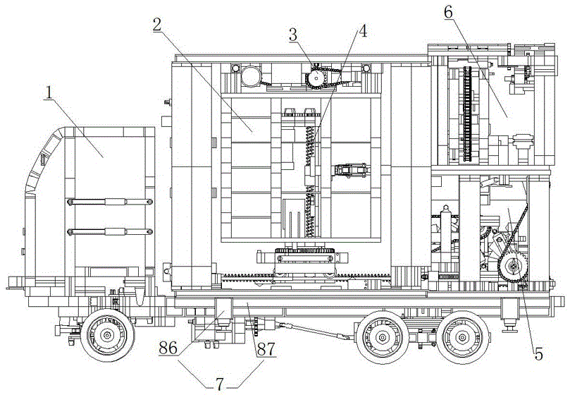
图1为本发明整体结构示意图。Figure 1 is a schematic diagram of the overall structure of the present invention.
图2为储物区整体立体结构示意图。Fig. 2 is a schematic diagram of the overall three-dimensional structure of the storage area.
图3为图2中主视结构示意图。Fig. 3 is a schematic diagram of the front view structure in Fig. 2 .
图4为图2中俯视结构示意图。FIG. 4 is a schematic top view of the structure in FIG. 2 .
图5为图2中左视结构示意图。Fig. 5 is a schematic diagram of the left view in Fig. 2 .
图6为取件装置俯视结构示意图。Fig. 6 is a schematic top view of the pick-up device.
图7为取件装置左视结构示意图。Fig. 7 is a schematic diagram of the left view of the pick-up device.
图8为夹持器立体结构示意图。Fig. 8 is a schematic diagram of the three-dimensional structure of the holder.
图9为寄取件平台整体立体结构示意图。Fig. 9 is a schematic diagram of the overall three-dimensional structure of the delivery and pick-up platform.
图10为图9中寄取件平台主视结构示意图。Fig. 10 is a schematic structural diagram of the front view of the delivery and pick-up platform in Fig. 9 .
图11为图9中寄取件平台左视结构示意图。Fig. 11 is a left view structural schematic diagram of the mailing and picking platform in Fig. 9 .
图12为无人机送件装置侧视结构示意图。Fig. 12 is a schematic diagram of the side view structure of the delivery device of the drone.
图13为图12中停机平台升降机构整体立体结构示意图。Fig. 13 is a schematic diagram of the overall three-dimensional structure of the lifting mechanism of the parking platform in Fig. 12 .
图14为图13中停机平台升降机构主视结构示意图。Fig. 14 is a front structural schematic diagram of the lifting mechanism of the parking platform in Fig. 13 .
图15为图13中停机平台升降机构俯视结构示意图。Fig. 15 is a top structural schematic diagram of the lifting mechanism of the parking platform in Fig. 13 .
图16为图13中停机平台升降机构侧视结构示意图。Fig. 16 is a schematic side view of the lifting mechanism of the parking platform in Fig. 13 .
图17为自动舱门机构整体立体结构示意图。Fig. 17 is a schematic diagram of the overall three-dimensional structure of the automatic hatch mechanism.
图18为图17中自动舱门机构主视结构示意图。Fig. 18 is a front structural schematic diagram of the automatic hatch mechanism in Fig. 17 .
图19为图17中自动舱门机构俯视结构示意图。Fig. 19 is a schematic top view of the automatic hatch mechanism in Fig. 17 .
图20为图17中自动舱门机构侧视结构示意图。Fig. 20 is a schematic diagram of the side view of the automatic door mechanism in Fig. 17 .
图21为图17中自动舱门机构仰视结构示意图。Fig. 21 is a schematic bottom view of the automatic hatch mechanism in Fig. 17 .
图22为外部辅助装件装置整体立体结构示意图。Fig. 22 is a schematic diagram of the overall three-dimensional structure of the external auxiliary mounting device.
图23为图22中外部辅助装件装置主视结构示意图。Fig. 23 is a front structural schematic diagram of the external auxiliary mounting device in Fig. 22 .
图24为图22中外部辅助装件装置俯视结构示意图。FIG. 24 is a schematic top view of the external auxiliary mounting device in FIG. 22 .
图25为图22中外部辅助装件装置左视结构示意图。Fig. 25 is a left view structural diagram of the external auxiliary mounting device in Fig. 22 .
图26为图22中外部辅助装件装置右视结构示意图。Fig. 26 is a right view structural diagram of the external auxiliary mounting device in Fig. 22 .
图27为用户自提方式流程框图。Fig. 27 is a flow chart of the user self-pick-up method.
图28为寄件模式流程框图。Fig. 28 is a flow chart of the sending mode.
具体实施方式Detailed ways
下面结合实施例对本发明做详细说明:本实施例是以本发明技术方案为前提进行实施,给出了详细的实施方式和具体的操作过程,但本发明的保护范围不限于下面的实施例。The present invention is described in detail below in conjunction with embodiment: present embodiment is implemented on the premise of technical solution of the present invention, has provided detailed embodiment and concrete operation process, but protection scope of the present invention is not limited to following embodiment.
如图1所示,本实施例中的一种智能快递装置,它包括运载车1与车厢,车厢可拆卸地安装于运载车1上,其中:所述车厢包括储物区2、储物区展开装置3、取件装置4、寄取件平台5、无人机送件装置6和液压举升装置7,所述寄取件平台5包括寄件平台与取件平台,所述取件平台包括取件平台A区与取件平台B区;As shown in Figure 1, a kind of intelligent courier device in the present embodiment, it comprises
所述储物区2设置于车厢的前部,储物区2包括固定储物区8、活动储物区A9和活动储物区B10,固定储物区8固定设置于车厢前部,活动储物区A9与活动储物区B10对称设置于固定储物区8右方的前后两侧面上;The
所述储物区展开装置3设置于车厢的顶部,储物区展开装置3包括运动悬臂,活动储物区A9与活动储物区B10安装于所述运动悬臂上;所述车厢顶部还设置有自动舱门;The storage
所述取件装置4安装于车厢底面的中部,取件装置4为末端安装有夹持器19的五自由度直角坐标机械手;The pick-up
所述车厢的后部设置有上下两层,其中下层为寄取件平台5,通过可转位式链式输送装置将快件由取件装置4的工作区分流至所述取件平台A区或取件平台B区,反之将快件从寄件平台上取下并输送至取件装置4的工作区;车厢的上层为无人机送件装置6,无人机送件装置6上设置有无人机,由步进电机驱动无人机送件装置6将无人机提升至预定高度,所述自动舱门自动打开,完成无人机起飞或者回收;The rear portion of the carriage is provided with upper and lower floors, wherein the lower floor is a pick-up platform 5, and the express mail is diverted from the working area of the pick-up
车厢底部与运载车1之间安装有液压举升装置7,用于车厢安装在载运车上或者车厢从运载车上拆卸下来。A
进一步地,所述运载车1为轻型平板运输车,所述载运车主要由动力部分、转向部分、车架部分、悬架部分四个部分组成,整个装置采用电力拖动方式,其特征在于:以一对并列位于车架中部的大功率电机为驱动,配合大速比减速齿轮箱,将动力利用万向联轴器输入至后桥;由控制板进行电子调速,输出有8速度等级模型数值;转向部分为电动转向系,位于装置前端的驱动电机带动齿轮减速箱运动,齿轮减速箱在齿条固定齿条上滑动,利用齿轮齿条机构将运动转化为转向滑块的平移运动;转向滑块机构带动四杆机构和前置梯形机构运动,带动位于两梯形边上的车轮绕转向轴同步摆动;车架部分为阵式结构,以角梁为主要结构单元,将动力部分、转向部分、悬架部分集成一体;前轮采用独立悬架,后轮采用非独立式板式弹簧悬架,板簧中部和两端设置铰接点,与车架连接,传递各种力和力矩,两端与双后桥铰接。Further, the
进一步地,车厢上表面设置有太阳能光伏板,将太阳能转换为电能为本装置内的电气元件提供电能。Further, the upper surface of the compartment is provided with a solar photovoltaic panel, which converts solar energy into electrical energy to provide electrical energy for the electrical components in the device.
进一步地,所述液压举升装置包括液压缸86和承载梁87,两个承载梁87分别纵向分布在车厢底部,两个液压缸86的缸体前后固连在一个承载梁87上,另外两个液压缸86对称地固连在另一个承载梁上,四个液压缸86的活塞杆同步运动驱动车厢的举升与下降。Further, the hydraulic lifting device includes a
如图2至图5所示,所述储物区2包括若干用于存放快件的储物格,储物格为密集窄体格架,每个储物格底面的托板中部镂空,每个储物格分别有唯一的编号。As shown in Figures 2 to 5, the
进一步地,所述储物区2中储物格的大小根据快件尺寸设置多种规格。Further, the size of the storage compartments in the
进一步地,所述储物区展开装置3包括直线导轨15、16,传动螺母、通过轴承固定于车厢顶部的传动丝杠和两个驱动电机11、12,两个驱动电机11、12分别设置于所述活动储物区A9与活动储物区B10的上方,两个传动螺母分别对应安装于活动储物区A9与活动储物区B10的上表面上,活动储物区A9与活动储物区B10挂载于直线导轨15、16上,传动螺母对应安装于传动丝杠上,控制器向两个驱动电机11、12同时发出运动信号,驱动电机11、12通过减速链传动机构13、14驱动传动丝杠转动,传动丝杠通过丝杠螺母机构将旋转运动转换为直线运动,活动储物区A9与活动储物区B10沿直线导轨15、16同步作相向运动或相背运动,两侧活动储物区A9与活动储物区B10同步展开或关闭,运动标准行程为储物区的宽度,当挡块触动限位开关17、18,活动储物区A9与活动储物区B10运动即停止。Further, the storage
如图6至图8所示,所述取件装置4是一台基于直角坐标关节的五自由度机械手,包括实现X、Y、Z三个方向移动自由度的直角坐标关节和可实现机械手末端夹持器19绕X轴和立柱31绕Z轴的旋转自由度的旋转关节,所述旋转关节包括X轴旋转运动模组和Z轴旋转运动模组;所述直角坐标关节包括X轴平移运动模组、Y轴平移运动模组、Z轴平移运动模组;Y轴平移运动模组设置于连接架23上,X轴平移运动模组驱动连接架23沿X方向运动;As shown in Figures 6 to 8, the pick-up
所述X轴平移运动模组包括直流大功率电机x20、X轴直线导轨21、22,车轮38、丝杠x24、螺母x,直流大功率电机x20固定于车厢主体的底板上,设置于固定储物区8的下方,两个X轴直线导轨21、22固定于车厢主体的底板上并分别设置于活动储物区A9与活动储物区B10的下方,X轴直线导轨21、22承受机械手载荷并引导连接架23在X方向作往复直线运动;所述连接架23的两侧下方各有一对车轮38,两侧车轮38分别沿所述X轴直线导轨21、22往复式滑动;直流大功率电机x20输出轴与丝杠x24的轴心通过刚性联轴器连接,并通过固连在连接架23下方的丝杠螺母机构将直流大功率电机x20的旋转运动转化为连接架23沿X方向的平移运动;The X-axis translation movement module includes a DC high-power motor x20, X-axis
所述Y轴平移运动模组包括输送电机y、Y轴直线导轨25、旋转基座26、减速箱y、齿条27,所述旋转基座26设置于连接架23的上方,旋转基座26下方的凸台与连接架23相配合,旋转基座可26沿连接架23做Y方向的平移运动;Y轴直线导轨25和齿条27相互平行地设置于连接架23的内部;减速箱y固定于旋转基座26的下方,输送电机y的电机转子为减速箱y提供动力来源,通过齿轮齿条机构带动旋转基座26实现机械手沿Y方向的平移运动;The Y-axis translation movement module includes a conveying motor y, a Y-axis
所述Z轴平移运动模组包括输送电机z、立柱31、旋转底座28、Z轴直线导轨32、舵机z29、减速箱z33、丝杠z34、螺母z35,旋转底座28设置于旋转基座26的内部并与旋转基座26构成转动副,可以实现旋转底座28与旋转基座26的相对转动;立柱31固连在旋转底座28的上方,Z轴直线导轨32设置于立柱31的两侧,输送电机z设置于立柱31的上方,输送电机z的输出轴作为减速箱z33的输入轴;丝杠z34固定设置于旋转底座28的上方并与Z轴直线导轨32相互平行,丝杠z34作为减速箱z33的输出轴;舵机z29的底座与螺母z35相连接,通过丝杠螺母机构将输送电机z的旋转运动转化为舵机z29沿Z方向的升降运动;The Z-axis translation movement module includes a conveying motor z, a
所述X轴旋转运动模组包括机械手末端夹持器19,所述舵机z29的输出轴与机械手末端夹持器19的底板39固连,通过舵机z29的运转实现机械手末端夹持器19绕X轴的旋转运动;所述Z轴旋转运动模组包括编码电机36、旋转基座26、旋转底座28和行星齿轮37,编码电机36固连在旋转底座28的上方驱动行星齿轮37并起行星架的作用,旋转基座26的边沿设置有与行星齿轮37相啮合的齿圈,旋转基座26、旋转底座28与行星齿轮37共同实现旋转底座28相对于旋转基座26绕Z轴方向的转动。The X-axis rotation movement module includes a
进一步地,所述机械手末端夹持器19包括舵机a40、舵机b41、连杆a42、连杆b43、连杆c44、夹持板45和防滑垫46,夹持板45的内表面覆盖有防滑垫46,连杆a42、连杆b43、连杆c44和舵机a40的机架依次构成转动副,形成一个呈平行四边形的平面连杆机构,舵机a40的输出轴与连杆a42固连,夹持板45与连杆b43固连,舵机a40的旋转运动驱动夹持板45作平移运动;夹持器由两个对称的呈平行四边形的平面连杆机构构成,两侧对称设置的平面连杆机构通过控制舵机a40和舵机b41的旋转角度来控制两个夹持板45的闭合与展开,实现夹持器的夹持动作与松开动作。Further, the
如图9至图11所示,所述寄取件平台由可转位式链式输送装置、取件平台和寄件平台组成:As shown in Figures 9 to 11, the delivery and pick-up platform is composed of an indexable chain conveyor, a pick-up platform and a delivery platform:
所述可转位式链式输送装置设置于车厢后部的下层,输送装置的底部设置有蜗轮47,输送装置的底部与蜗轮47相配合地设置有蜗杆49,固连于车厢底板上的直流电机a48驱动蜗轮蜗杆机构实现输送装置的旋转运动;车厢底板上使输送装置正对寄件口和取件口的相应位置分别设有限位开关,输送装置旋转到寄件平台或者取件平台的入口位置处即停止转动;输送装置上部安装有链式输送带50,链式输送带50的前端设置于机械手的工作空间内,链式输送带50的两侧设置有光电接近开关51,直流电机通过链轮驱动链式输送带50运动,链式输送带50运动驱动输送装置同步向前或向后运动;The indexable chain conveyor is arranged on the lower floor at the rear of the compartment, the bottom of the conveyor is provided with a
所述寄件平台设置于链式输送装置的后方,直流电机b52通过蜗轮蜗杆传动机构53驱动平行四边形机构54实现寄件平台的抬升运动,寄件平台的宽度不小于输送带的宽度,寄件平台表面运动至与输送带带面相贴合的位置时触发限位开关,运动停止;寄件平台表面的远端极限位置的上方隔板上安装有用于将快件从寄件平台推动至输送带的刮板机构,所述刮板机构由固定于寄件平台平行四边形机构另一侧的链轮55驱动,通过链传动将运动传递至固定于隔板上的小链轮56并带动凸轮57转动,利用凸轮机构将旋转运动转化为凸轮顶杆58的平动,再通过曲柄滑块机构59实现刮板0°~95°的转动;The mailing platform is arranged at the rear of the chain conveying device. The DC motor b52 drives the
所述取件平台设置于链式输送装置的右侧,取件平台为30°光滑斜面60,快件从链式输送装置的输送带上滑落至取件平台,通过挡板61将快件分配至取件口A或取件口B;挡板由取件平台下方的微型电机驱动,挡板转轴与电机输出轴通过万象联轴器连接,挡板的两个运动极位均设有限位开关62、63;在取件平台出口的上方设置有人机交互的LCD显示屏。The pick-up platform is arranged on the right side of the chain conveyor, and the pick-up platform is a 30 °
如图12至图21所示,所述无人机送件装置包括快件装载机构64、停机平台升降机构65和自动舱门机构66,机械手将快件送入无人机送件装置的入口后松开,快件在重力作用下由倾斜的辊筒输送机67滑入设置于辊筒输送机67末端并位于停机平台升降机构65下方的载物舱68内,停机平台升降机构65带动无人机下降至载物舱68的上方,无人机夹持机构将载物舱68夹紧并装载到其腹部,完成装载工作;As shown in Fig. 12 to Fig. 21, described unmanned aerial vehicle conveying device comprises fast
无人机装载载物舱68置于辊筒输送机67的末端,停机平台两侧由双侧弯板链扣安装于两侧的升降链条69上,固定在车厢后部上层底板的无人机装载电机70驱动无人机装载减速箱71将动力传递给设置于分动箱内部的主动锥齿轮,与主动锥齿轮相啮合的对置分动锥齿轮72将运动分解成两个反向的旋转运动,分动锥齿轮轴的另一端与分动蜗杆73刚性连接,与分动蜗杆73相啮合的分动蜗轮74安装在升降链条下部的链轮轴上,利用蜗轮蜗杆减速机构带动链轮转动实现停机平台的升降运动;在平台升降极位均设有限位开关限定行程;The unmanned aerial vehicle
所述自动舱门机构66设置于停机平台的正上方,固定于顶板上的舱门直流电机75通过舱门齿轮减速箱76将运动传递到齿轮a77,齿轮b78设置于齿轮a77的上方并与齿轮a77相啮合,固连于齿轮b78中心轴另一端的齿轮c79与舱门轴齿轮d80啮合,通过直流电机驱动门轴旋转运动;齿轮b78通过过轮一81和过轮二82将电机动力传至齿轮e83,齿轮b78与齿轮e83转速相同转向相反,通过齿轮e83将动力传至舱门轴齿轮84驱动另一门轴转动,通过控制舱门直流电机75转动的圈数和转动的方向控制舱门85的开启或者闭合。Described
如图22至图26所示,在本装置的外部还设置有辅助装件装置,辅助装件装置为一台可实现沿X方向、Y方向作平移运动和绕X轴、Y轴和Z轴作旋转运动的五自由度机械手,主要完成快件在快递车本体的外部装载和卸载工作。所述五自由度机械手运动主要包括:基座88沿X方向平移运动、立柱104绕Z方向旋转运动、大臂89沿Y方向的平移运动、小臂90沿Z方向的升降运动和小臂末端绕Y方向的旋转运动。平移关节包括X轴平移运动模组、Y轴平移运动模组。旋转关节包括X轴旋转运动模组、Y轴旋转运动模组和Z轴旋转运动模组;As shown in Figure 22 to Figure 26, an auxiliary loading device is also provided outside the device. The auxiliary loading device is a set that can realize translational movement along the X direction and Y direction and around the X axis, Y axis and Z axis. The five-degree-of-freedom manipulator with rotating motion mainly completes the external loading and unloading of express mail on the express car body. The movement of the five-degree-of-freedom manipulator mainly includes: the translational movement of the
在所述辅助装件装置中:X轴平移运动模组包括直流驱动电机91、减速箱92、基座平台93、X轴直线导轨94、链条95、丝杠96、螺母、限位开关97、移动平台98。直流驱动电机1及齿轮减速箱位于基座平台之上,减速箱输出齿轮作为链条传动输入齿轮。丝杠轴置于基座平台上,并与链条传动输出齿轮轴固连。直线导轨平行于丝杠固连于基座平台上。螺母与移动平台固连,直流驱动电机1通过链传动利用丝杠螺母机构实现移动平台及上部机械手沿X方向的平移运动。限位开关根据储物格位置放置于基座平台上,用于检测机械手位置;In the auxiliary loading device: the X-axis translational movement module includes a DC drive motor 91, a
在所述辅助装件装置中:所述Z轴旋转运动模组包括移动平台98、旋转基座99、旋转底座、蜗杆100、直流电机101、减速箱102、码盘。旋转底座固定于移动平台上,并与旋转基座配合。旋转基座边缘设置有齿圈,与其旁边的蜗杆配合,组成蜗轮蜗杆机构。直流电机轴与减速箱输入轴相连,并固定于移动平台上。减速箱输出轴与蜗杆轴固连,通过直流电机的旋转、实现机械臂绕Z轴方向的转动。蜗杆轴的另一端安装码盘,通过控制脉冲个数控制旋转角度;In the auxiliary loading device: the Z-axis rotary motion module includes a
在所述辅助装件装置中:所述Y轴平移运动模组包括Y轴直线导轨103、大臂89、旋转基座、立柱104、丝杠、螺母、直流电机105、减速器106。立柱位于旋转基座的上方。两根Y轴直线导轨与丝杠位于立柱上方且导轨与丝杠互相平行。直流电机位于立柱上方,其输出轴作为减速器输入轴。减速器的输出轴与丝杠的一端刚性连接,而丝杠的另一端安装码盘,用于控制大臂位移距离。螺母与丝杠配合并固定于大臂89下方,直流电机转动,通过丝杠螺母机构,实现大臂沿Y方向的伸缩运动;In the auxiliary loading device: the Y-axis translation movement module includes a Y-axis
在所述辅助装件装置中:所述X轴旋转运动模组包括直流电机107、减速箱108、丝杠109、螺母滑块110、齿轮111、齿轮112、齿轮113、曲柄滑块机构、平行四边形机构。直流电机、齿轮111、齿轮112、齿轮113、丝杠固定于于大臂上方。直流电机驱动减速箱将动力输出至齿轮111,与之相啮合的齿轮112带动丝杠转动,丝杠螺母机构将电机旋转运动转换为螺母滑块110沿Y轴方向的直线运动。连杆114通过铰链与螺母滑块110和曲柄115相连,曲柄滑块机构将螺母滑块110的直线运动转换为曲柄绕铰链的旋转运动。曲柄与平行四边形机构的一边固连,从而实现机械手小臂绕X轴的旋转运动,平行四边向机构保证机械手末端件始终保持垂直于地面。齿轮113与齿轮112相啮合,齿轮113轴的另一端安装码盘,用于控制机械手小臂绕X轴旋转角度。In the auxiliary loading device: the X-axis rotary motion module includes a
在所述辅助装件装置中:所述Y轴旋转运动模组包括舵机116、机械手末端夹持器117。舵机116的机架固连于机械手小臂末端,舵机116输出轴与机械手末端夹持器底板固连,通过舵机116的运转,可实现机械手末端夹持器绕Y轴的旋转运动。In the auxiliary loading device: the Y-axis rotary motion module includes a
外部辅助装件装置机械臂末端夹持器结构与前述取件装置机械臂末端夹持器结构相同,在此不再叙述。The structure of the gripper at the end of the mechanical arm of the external auxiliary loading device is the same as that of the gripper at the end of the mechanical arm of the aforementioned pick-up device, and will not be described here.
使用过程中:During use:
1、外部辅助装件装置工作在配送中心,将其安装于快件输送带和车厢装件区,装件装置末端夹持器将快件抓起,根据快件外形尺寸分配对应架格,通过控制器调整机械手位姿,将快件从外部准确送往车厢的架格中。多台装件装置分别从车厢的三面装入快件,提高装件效率。1. The external auxiliary loading device works in the distribution center. It is installed on the express conveyor belt and the loading area of the carriage. The end gripper of the loading device grabs the express, and allocates the corresponding rack according to the shape and size of the express, and adjusts it through the controller. The pose of the manipulator accurately sends the express from the outside to the shelf of the carriage. Multiple loading devices load express items from three sides of the carriage respectively to improve loading efficiency.
2、用户自提方式:其流程框图如图27所示,载运车将车厢运送至指定位置并将车厢分离放置于预定地点,并自动启动储物区展开装置,将活动储物区展开,取件装置自动复位,车厢进入服务状态。车厢内部控制器向用户客户端发送取件消息,通知用户根据自身需要预约取件时间,按照车厢取件功能设计,同一时间段内可允许两人同时操作。用户按照预约时间取件时,在扫码窗口扫描用户客户端收到的取件二维码,或者在操作面板上输入取件码,进行信息读取与安全匹配,车厢控制器向取件装置发出运动指令,将取件机械手末端夹持器移动到目标位置,并将快件取出,取件装置继续运动,在控制器的运动指令下调整机械手末端夹持器的位置,将快件运送至可转位式链式输送装置的前端入口处,夹持器向Z轴负方向移动一定距离,将快件卸载至输送带上,取件装置完成工作并复位待命,链式输送装置开始工作并转位至区间平台入口处,快件从链式输送装置的输送带上滑落至取件平台,通过挡板分配至取件口A和取件口B,用户从取件口取走快件,完成取件过程。2. User self-pick-up method: the flow chart is shown in Figure 27. The carrier transports the compartment to the designated location and separates the compartment and places it at the predetermined location, and automatically activates the storage area expansion device to unfold the movable storage area and take it out. The component device automatically resets, and the carriage enters the service state. The internal controller of the compartment sends a pick-up message to the user client, informing the user to reserve a pick-up time according to their own needs. According to the compartment pick-up function design, two people can operate at the same time at the same time. When the user picks up the item according to the scheduled time, scan the QR code received by the user client in the scanning window, or enter the pickup code on the operation panel to read the information and perform security matching. Issue a motion command to move the end gripper of the pick-up manipulator to the target position, take out the express piece, the pick-up device continues to move, adjust the position of the end gripper of the manipulator under the movement command of the controller, and transport the express piece to the transferable At the entrance of the front end of the position-type chain conveyor, the gripper moves a certain distance in the negative direction of the Z-axis to unload the express onto the conveyor belt. At the entrance of the interval platform, the express mail slides from the conveyor belt of the chain conveyor device to the pick-up platform, and is distributed to the pick-up port A and pick-up port B through the baffle, and the user takes the express mail from the pick-up port to complete the pick-up process.
3、无人机派送方式:用户在预约取件时间后,可选择无人机派送模式,在进行确认及其他操作之后,车厢控制器接受派送命令,在进行信息读取与安全匹配后,控制器向取件装置发出运动指令,将取件机械手末端夹持器移动到目标位置,并将快件取出,在控制器的运动指令下调整机械手末端夹持器的位置,将其运送至车厢后端上层的辊筒输送机入口处,此时夹持器将快件松开,快件通过辊筒输送机滑入位于停机平台升降机构下方的载物舱内,取件装置完成工作并复位待命,停机平台升降机构带动无人机下降至载物舱的上方,无人机夹持机构将载物舱夹紧并装载到其腹部,完成装载工作;之后停机平台升降机构开始运动,将专用送件无人机提升至预定高度,同时,车厢顶部的自动舱门打开,无人机携带快件起飞前往目标位置。之后,自动舱门关闭。用户从载物舱取出快件后,无人机返航,当接近自动舱门位置时,自动舱门打开,无人机回收,完成无人机派送任务。3. UAV delivery mode: After booking the pick-up time, the user can choose the UAV delivery mode. After confirmation and other operations, the car controller accepts the delivery command, and after information reading and safety matching, control The device sends a motion command to the pickup device, moves the end gripper of the pickup manipulator to the target position, and takes out the express, adjusts the position of the end gripper of the manipulator under the motion command of the controller, and transports it to the rear end of the carriage At the entrance of the roller conveyor on the upper layer, the gripper releases the express piece at this time, and the express piece slides through the roller conveyor into the load compartment under the lifting mechanism of the parking platform, the pick-up device completes the work and resets to stand by, and the stop platform The lifting mechanism drives the drone down to the top of the loading compartment, and the clamping mechanism of the drone clamps the loading compartment and loads it on its abdomen to complete the loading work; after that, the lifting mechanism of the parking platform starts to move, and the special delivery unmanned The drone is lifted to a predetermined height, and at the same time, the automatic hatch on the top of the compartment opens, and the drone takes off with the express to the target location. Afterwards, the automatic hatch closes. After the user takes out the express from the loading compartment, the UAV returns to the voyage. When it is close to the position of the automatic hatch, the automatic hatch opens, and the UAV is recovered to complete the delivery task of the UAV.
4、寄件模式:其流程框图如图28所示,寄件时,用户在操作面板点击寄件按钮,在进行确认及其他操作之后,车厢控制器生成寄件任务,寄件口打开,用户将快件放置于寄件装置上表面的专用E形平板上,直流电机驱动平行四边形机构运动,完成快件的抬升和传递动作。快件移至链式输送带入口处时,上方隔板处的刮板机构将快件从寄件平台推动至链式输送带上,平行四边形机构复位,同时取件装置运动至链式输送带的出口处,输送带运动,将快件输送到机械手末端取件板上,控制器检索空余架格,进行路径规划,向取件装置发出运动指令,将取件机械手末端取件板移动到目标位置,并将快件装入,取件装置复位,寄件完成。4. Mailing mode: the flow chart is shown in Figure 28. When sending mail, the user clicks the mailing button on the operation panel, and after confirmation and other operations, the carriage controller generates a mailing task, the mailing port opens, and the user Place the express on the special E-shaped plate on the upper surface of the sending device, and the DC motor drives the parallelogram mechanism to complete the lifting and delivery of the express. When the shipment moves to the entrance of the chain conveyor belt, the scraper mechanism at the upper partition pushes the shipment from the sending platform to the chain conveyor belt, the parallelogram mechanism resets, and the pick-up device moves to the exit of the chain conveyor belt At the position, the conveyor belt moves to transport the express to the pick-up plate at the end of the manipulator, the controller retrieves the vacant racks, performs path planning, sends a motion command to the pick-up device, moves the pick-up plate at the end of the pick-up manipulator to the target position, and Load the express mail, reset the pick-up device, and send the mail is completed.
5、车厢在运载车上的卸装:当快递车到达快递分发站点时,需要车厢从运载车上卸下。使运载车停在放置车厢的适当位置时,启动电机,带动油泵从油箱中吸入压力油送到液压缸中使活塞杆做伸长运动,到达最大极限位置时,活塞杆通过承载梁将车厢举起,车厢与运载车分离,此时将运载车开出,车厢便放置在目标位置;当车厢需要返回物流配送中心时,需要将车厢装载到运载车上。首先,将运载车停放在适当位置,使后部平板置于车厢下方;然后,启动电机,带动油泵从液压缸中吸出压力油送到油箱使活塞杆做收缩运动,到达最小极限位置时,运载车后部平板将车厢撑起;最后,插入固定销,运载车便可将车厢运输到物流配送中心。5. Unloading of carriages on the delivery vehicle: When the express delivery vehicle arrives at the express distribution site, the carriages need to be unloaded from the delivery vehicle. When the carrier vehicle is parked at an appropriate position for placing the compartment, start the motor to drive the oil pump to suck pressure oil from the oil tank and send it to the hydraulic cylinder to make the piston rod do the elongation movement. At this time, when the carrier is driven out, the car is placed at the target position; when the car needs to be returned to the logistics distribution center, the car needs to be loaded onto the carrier. Firstly, park the carrier vehicle in a proper position so that the rear plate is placed under the compartment; then, start the motor to drive the oil pump to suck out the pressure oil from the hydraulic cylinder and send it to the fuel tank to make the piston rod do contraction movement. When it reaches the minimum limit position, the carrier The flat plate at the rear of the vehicle props up the compartment; finally, the fixing pins are inserted, and the carrier can transport the compartment to the logistics distribution center.
以上所述,仅为本发明的具体实施方式,但本发明的保护范围并不局限于此,任何熟悉技术领域的技术人员在本发明揭露的技术范围内,可轻易想到的变化或替换,都应涵盖在本发明的保护范围之内。因此,本发明的保护范围应以所述权利要求的保护范围为准。The above is only a specific embodiment of the present invention, but the scope of protection of the present invention is not limited thereto. Any changes or substitutions that can be easily conceived by those skilled in the art within the technical scope disclosed in the present invention are all Should be covered within the protection scope of the present invention. Therefore, the protection scope of the present invention should be determined by the protection scope of the claims.
Claims (7)
Priority Applications (1)
| Application Number | Priority Date | Filing Date | Title |
|---|---|---|---|
| CN201710928439.4A CN107599938B (en) | 2017-10-09 | 2017-10-09 | An intelligent express delivery device |
Applications Claiming Priority (1)
| Application Number | Priority Date | Filing Date | Title |
|---|---|---|---|
| CN201710928439.4A CN107599938B (en) | 2017-10-09 | 2017-10-09 | An intelligent express delivery device |
Publications (2)
| Publication Number | Publication Date |
|---|---|
| CN107599938A CN107599938A (en) | 2018-01-19 |
| CN107599938B true CN107599938B (en) | 2023-07-07 |
Family
ID=61068106
Family Applications (1)
| Application Number | Title | Priority Date | Filing Date |
|---|---|---|---|
| CN201710928439.4A Expired - Fee Related CN107599938B (en) | 2017-10-09 | 2017-10-09 | An intelligent express delivery device |
Country Status (1)
| Country | Link |
|---|---|
| CN (1) | CN107599938B (en) |
Families Citing this family (14)
| Publication number | Priority date | Publication date | Assignee | Title |
|---|---|---|---|---|
| CN108944624A (en) * | 2018-07-12 | 2018-12-07 | 福建工程学院 | A kind of automated intelligent logistics express delivery dispensing vehicle and its application method |
| CN109191719B (en) * | 2018-08-13 | 2021-01-08 | 深圳蓝胖子机器人有限公司 | Express delivery cabinet, express delivery method, robot and computer storage medium |
| CN109243090B (en) * | 2018-08-13 | 2021-08-20 | 深圳蓝胖子机器人有限公司 | Express cabinet, express sending method, robot and computer storage medium |
| CN108791575B (en) * | 2018-08-22 | 2023-08-04 | 大连民族大学 | Food carrier |
| CN109492967A (en) * | 2018-10-26 | 2019-03-19 | 同济大学 | A kind of Intelligent logistics method |
| CN109598469A (en) * | 2018-12-02 | 2019-04-09 | 杭州迅蚁网络科技有限公司 | Automated warehouse logistics distribution system |
| CN110065759B (en) * | 2019-06-03 | 2024-02-06 | 湖北三丰小松物流技术有限公司 | Four-wheel drive four-link rod sleeved type four-way shuttle robot |
| CN112456174A (en) * | 2020-12-04 | 2021-03-09 | 阮俊 | Commodity circulation supply conveyer for delivery convenient to loading is unloaded |
| CN113003228B (en) * | 2021-02-10 | 2022-12-20 | 北京二郎神科技有限公司 | Cargo distribution system and distribution method, cargo transfer mechanism and cargo transfer method |
| CN114211506A (en) * | 2021-12-17 | 2022-03-22 | 重庆特斯联智慧科技股份有限公司 | Intelligent and efficient express delivery distribution robot |
| CN114535134B (en) * | 2022-01-17 | 2023-10-20 | 中国邮电器材集团有限公司 | Automatic sorting system and automatic sorting method for parcel |
| CN116729233B (en) * | 2023-02-20 | 2025-10-21 | 西安中通巡天科技有限公司 | An unmanned logistics vehicle and its vehicle group |
| CN116639288B (en) * | 2023-07-24 | 2023-11-10 | 国网四川省电力公司成都供电公司 | Unmanned aerial vehicle intelligent mobile airport and automatic lifting platform thereof |
| CN117360841B (en) * | 2023-10-26 | 2025-11-07 | 西南交通大学 | Automatic receiving unmanned aerial vehicle device for vehicle-mounted unmanned aerial vehicle |
Citations (6)
| Publication number | Priority date | Publication date | Assignee | Title |
|---|---|---|---|---|
| DE4342357A1 (en) * | 1993-12-11 | 1994-05-11 | Gottfried Von Czarnowski | Car park built on principle of high shelf warehouse - uses exclusively vertical and horizontal movement of lift for car handling |
| JPH07251667A (en) * | 1994-03-15 | 1995-10-03 | Takashi Yoshimoto | Selecting lift/storage device for cargo container |
| CN104314483A (en) * | 2014-10-27 | 2015-01-28 | 济南同日数控设备有限公司 | Automatic auxiliary workover rig |
| CN104590802A (en) * | 2014-12-26 | 2015-05-06 | 北京联合大学 | Automatic express delivery piece receiving and sending device |
| CN106494289A (en) * | 2016-12-09 | 2017-03-15 | 山东英才学院 | A kind of adjustable express delivery car in inner space |
| CN106541880A (en) * | 2016-10-25 | 2017-03-29 | 北京印刷学院 | A kind of Intelligent transportation device |
-
2017
- 2017-10-09 CN CN201710928439.4A patent/CN107599938B/en not_active Expired - Fee Related
Patent Citations (6)
| Publication number | Priority date | Publication date | Assignee | Title |
|---|---|---|---|---|
| DE4342357A1 (en) * | 1993-12-11 | 1994-05-11 | Gottfried Von Czarnowski | Car park built on principle of high shelf warehouse - uses exclusively vertical and horizontal movement of lift for car handling |
| JPH07251667A (en) * | 1994-03-15 | 1995-10-03 | Takashi Yoshimoto | Selecting lift/storage device for cargo container |
| CN104314483A (en) * | 2014-10-27 | 2015-01-28 | 济南同日数控设备有限公司 | Automatic auxiliary workover rig |
| CN104590802A (en) * | 2014-12-26 | 2015-05-06 | 北京联合大学 | Automatic express delivery piece receiving and sending device |
| CN106541880A (en) * | 2016-10-25 | 2017-03-29 | 北京印刷学院 | A kind of Intelligent transportation device |
| CN106494289A (en) * | 2016-12-09 | 2017-03-15 | 山东英才学院 | A kind of adjustable express delivery car in inner space |
Non-Patent Citations (1)
| Title |
|---|
| 智能快递车自助寄取快递系统的设计;杨琪等;机电技术(第113期);2-6页 * |
Also Published As
| Publication number | Publication date |
|---|---|
| CN107599938A (en) | 2018-01-19 |
Similar Documents
| Publication | Publication Date | Title |
|---|---|---|
| CN107599938B (en) | An intelligent express delivery device | |
| CN207345649U (en) | A kind of fast delivery device of intelligence | |
| CN108341257B (en) | A sanitation robot used for transporting and unloading garbage bins and its control method | |
| CN107055030B (en) | Logistics dispatching system and dispatching method | |
| CN106493084B (en) | A kind of express delivery cabinet and the express transportation storage system with the express delivery cabinet | |
| CN103029966B (en) | The control system of the pallet trolley continuous board conveying device | |
| CN106004612B (en) | It is a kind of to send part logistic car automatically | |
| CN106733674A (en) | A kind of express transportation system and quick despatch sorting platform | |
| CN210236494U (en) | Automatic loading machine for bagged materials | |
| CN106269539B (en) | Autocontrol express delivery classifying cart | |
| CN113335798B (en) | A hospital robot waste management method and system | |
| CN210504790U (en) | Intelligent loading device | |
| CN110540044A (en) | Pick-up transmission mechanism, lifting transmission mechanism and multi-layer circulation intelligent transmission system | |
| CN210504425U (en) | Logistics distribution system | |
| CN107352278A (en) | A kind of control method of logistics code fetch system handler | |
| CN208485326U (en) | A kind of automatic loading machine | |
| CN207293220U (en) | Suitable for the logistics code fetch system of freight container | |
| CN212654926U (en) | Distribution cabinet | |
| CN108840122A (en) | A kind of automatic loading machine | |
| CN206382246U (en) | A kind of express transportation system and quick despatch sorting platform | |
| CN107553465A (en) | A kind of intelligent electric business merchandising machine people | |
| CN209160846U (en) | A kind of logistics unmanned plane dress easing gear | |
| CN109290214B (en) | Goods feeding mechanical arm capable of collecting information and goods feeding system | |
| CN112027693A (en) | Three-dimensional storage system and method for part storage | |
| CN208198224U (en) | A kind of intelligence express delivery dispensing vehicle |
Legal Events
| Date | Code | Title | Description |
|---|---|---|---|
| PB01 | Publication | ||
| PB01 | Publication | ||
| SE01 | Entry into force of request for substantive examination | ||
| SE01 | Entry into force of request for substantive examination | ||
| GR01 | Patent grant | ||
| GR01 | Patent grant | ||
| CF01 | Termination of patent right due to non-payment of annual fee | ||
| CF01 | Termination of patent right due to non-payment of annual fee |
Granted publication date: 20230707 |