CN107358631B - A Binocular Vision Reconstruction Method Considering 3D Distortion - Google Patents
A Binocular Vision Reconstruction Method Considering 3D Distortion Download PDFInfo
- Publication number
- CN107358631B CN107358631B CN201710496023.XA CN201710496023A CN107358631B CN 107358631 B CN107358631 B CN 107358631B CN 201710496023 A CN201710496023 A CN 201710496023A CN 107358631 B CN107358631 B CN 107358631B
- Authority
- CN
- China
- Prior art keywords
- camera
- distortion
- reconstruction
- image
- dimensional
- Prior art date
- Legal status (The legal status is an assumption and is not a legal conclusion. Google has not performed a legal analysis and makes no representation as to the accuracy of the status listed.)
- Active
Links
Images


Classifications
-
- G—PHYSICS
- G06—COMPUTING OR CALCULATING; COUNTING
- G06T—IMAGE DATA PROCESSING OR GENERATION, IN GENERAL
- G06T7/00—Image analysis
- G06T7/80—Analysis of captured images to determine intrinsic or extrinsic camera parameters, i.e. camera calibration
- G06T7/85—Stereo camera calibration
-
- G—PHYSICS
- G06—COMPUTING OR CALCULATING; COUNTING
- G06T—IMAGE DATA PROCESSING OR GENERATION, IN GENERAL
- G06T17/00—Three dimensional [3D] modelling, e.g. data description of 3D objects
-
- G—PHYSICS
- G06—COMPUTING OR CALCULATING; COUNTING
- G06T—IMAGE DATA PROCESSING OR GENERATION, IN GENERAL
- G06T5/00—Image enhancement or restoration
- G06T5/80—Geometric correction
-
- G—PHYSICS
- G06—COMPUTING OR CALCULATING; COUNTING
- G06T—IMAGE DATA PROCESSING OR GENERATION, IN GENERAL
- G06T2207/00—Indexing scheme for image analysis or image enhancement
- G06T2207/10—Image acquisition modality
- G06T2207/10004—Still image; Photographic image
- G06T2207/10012—Stereo images
-
- G—PHYSICS
- G06—COMPUTING OR CALCULATING; COUNTING
- G06T—IMAGE DATA PROCESSING OR GENERATION, IN GENERAL
- G06T2207/00—Indexing scheme for image analysis or image enhancement
- G06T2207/30—Subject of image; Context of image processing
- G06T2207/30244—Camera pose
Landscapes
- Engineering & Computer Science (AREA)
- Physics & Mathematics (AREA)
- General Physics & Mathematics (AREA)
- Theoretical Computer Science (AREA)
- Computer Vision & Pattern Recognition (AREA)
- Computer Graphics (AREA)
- Geometry (AREA)
- Software Systems (AREA)
- Image Processing (AREA)
- Other Investigation Or Analysis Of Materials By Electrical Means (AREA)
Abstract
本发明一种虑及三维畸变的双目视觉重建方法属于计算机视觉测量技术领域,涉及一种虑及三维畸变的双目视觉重建方法。该方法引入三维畸变修正函数对视觉重建的结果进行补偿优化,实现三维高精度重建。该方法首先采用传统双目视觉重建方法获得测量点的三维重建初值;然后基于标准物与双目相机的相对关系及重建初始值,求解三维畸变补偿值;进而对左右图像分别提取的被测点摄像机坐标进行畸变补偿;最终结合双目视觉原理重建,实现双目三维高精度重建。该方法重建精度高,可补偿双目视觉的三维畸变,实现具有大曲率大尺寸零件形面重建,提高双目视觉的三维重建精度。
The invention relates to a binocular vision reconstruction method considering three-dimensional distortion, belonging to the technical field of computer vision measurement, and relates to a binocular vision reconstruction method considering three-dimensional distortion. In this method, a 3D distortion correction function is introduced to compensate and optimize the results of visual reconstruction, so as to achieve 3D high-precision reconstruction. The method first uses the traditional binocular vision reconstruction method to obtain the initial 3D reconstruction value of the measurement point; then, based on the relative relationship between the standard and the binocular camera and the initial reconstruction value, the 3D distortion compensation value is obtained; Distortion compensation is performed on the coordinates of the point camera; finally, it is reconstructed with the principle of binocular vision to achieve high-precision binocular 3D reconstruction. The method has high reconstruction accuracy, can compensate for the three-dimensional distortion of binocular vision, realizes the shape and surface reconstruction of parts with large curvature and large size, and improves the three-dimensional reconstruction accuracy of binocular vision.
Description
技术领域technical field
本发明属于计算机视觉测量技术领域,涉及一种虑及三维畸变的双目视觉重建方法。The invention belongs to the technical field of computer vision measurement, and relates to a binocular vision reconstruction method considering three-dimensional distortion.
背景技术Background technique
双目机器视觉具有非接触,多信息,快速测量等优势,已在航天、航空大型零件测量中广泛应用。重建过程是实现双目视觉的空间三维场测量的重要环节,但是在传统的双目视觉重建中,只考虑了在平面范围的畸变变化,并为引入深度畸变的三维概念,因此在深度方向的测量精度较差。但是由于航天航空零件大型零件,三维尺寸大,且在深度方向的几何量变化也较大,因此,实现三维高精度重建对于面向航天航空现场测量至关重要。Binocular machine vision has the advantages of non-contact, multi-information, fast measurement, etc., and has been widely used in the measurement of large parts in aerospace and aviation. The reconstruction process is an important link to realize the spatial 3D field measurement of binocular vision, but in the traditional binocular vision reconstruction, only the distortion changes in the plane range are considered, and the 3D concept of depth distortion is introduced, so in the depth direction. The measurement accuracy is poor. However, due to the large size of aerospace parts, the large three-dimensional size, and the large geometric changes in the depth direction, the realization of three-dimensional high-precision reconstruction is very important for aerospace field measurement.
董明利等人发表的论文《随对焦状态与物距变化的畸变模型及标定方法[J].仪器仪表学报,2013,34(12):2653-2659.提出通过建立随对焦装袋和测量点物距变化的相机畸变模型,实现基于摄影测量原理的单相机三维高精度测量。冯颖;张欣;杜娟;苏比哈什·如凯迦等发明的“一种基于双目立体视觉系统的多视角三维重建方法”,专利号CN201610571315.0,通过提前对双目立体视觉系统摄像头进行标定,制作双目立体视觉系统恢复三维信息的查找表,完成对被重建物体多视角的三维重建。该方法可以固定场景的高精度重建,但是对于航空现场的大尺寸零件难以实现现场高精度重建。The paper published by Dong Mingli et al. "Distortion model and calibration method with changes in focus state and object distance [J]. Journal of Instrumentation, 2013, 34(12): 2653-2659. The camera distortion model of the object distance change realizes the three-dimensional high-precision measurement of a single camera based on the principle of photogrammetry. Feng Ying; Zhang Xin; Du Juan; Subhash Rukaiga and others invented "a multi-view 3D reconstruction method based on binocular stereo vision system", patent number CN201610571315.0, through the binocular stereo vision system in advance The camera is calibrated, and a look-up table for the binocular stereo vision system to recover three-dimensional information is made to complete the three-dimensional reconstruction of the reconstructed object from multiple perspectives. This method can fix the high-precision reconstruction of the scene, but it is difficult to achieve high-precision reconstruction of the scene for large-sized parts in the aviation field.
发明内容SUMMARY OF THE INVENTION
本发明要解决的技术难题是针对双目视觉对于大曲率零件的三维重建精度较低的问题,发明了虑及三维畸变的双目视觉重建方法。该方法引入三维畸变修正函数对视觉重建的结果进行补偿优化,实现三维高精度重建;通过以双目视觉测量结果为初值,然后基于标准物与双目相机的相对关系及重建初始值,求解三维畸变补偿值;进而对左右图像分别提取的被测点摄像机坐标进行畸变补偿;最终结合双目视觉原理重建,实现零件在三维空间的高精度重建。The technical problem to be solved by the present invention is to solve the problem of low 3D reconstruction accuracy of parts with large curvature by binocular vision, and a binocular vision reconstruction method considering 3D distortion is invented. In this method, a 3D distortion correction function is introduced to compensate and optimize the results of visual reconstruction, so as to achieve high-precision 3D reconstruction. By taking the binocular vision measurement result as the initial value, and then based on the relative relationship between the standard and the binocular camera and the initial value of reconstruction, the solution is obtained. Three-dimensional distortion compensation value; and then perform distortion compensation on the camera coordinates of the measured point extracted from the left and right images respectively; finally combined with the principle of binocular vision reconstruction, to achieve high-precision reconstruction of parts in three-dimensional space.
本发明采用的技术方案是一种虑及三维畸变的双目视觉重建方法,其特征是,该方法引入三维畸变修正函数对视觉重建的结果进行补偿优化,实现三维高精度重建;该方法首先采用传统双目视觉重建方法获得测量点的三维重建初值;然后基于标准物与双目相机的相对关系及重建初始值,求解三维畸变补偿值;进而对左右图像分别提取的被测点摄像机坐标进行畸变补偿;最终结合双目视觉原理重建,实现双目三维高精度重建;方法具体步骤如下:The technical solution adopted in the present invention is a binocular vision reconstruction method considering three-dimensional distortion, which is characterized in that the method introduces a three-dimensional distortion correction function to compensate and optimize the results of visual reconstruction, so as to realize three-dimensional high-precision reconstruction; the method first adopts The traditional binocular vision reconstruction method obtains the initial three-dimensional reconstruction value of the measurement point; then, based on the relative relationship between the standard and the binocular camera and the reconstruction initial value, the three-dimensional distortion compensation value is calculated; and then the camera coordinates of the measured point extracted from the left and right images are calculated. Distortion compensation; finally combined with binocular vision principle reconstruction, to achieve binocular 3D high-precision reconstruction; the specific steps of the method are as follows:
第一步三维重建初值计算The first step is to calculate the initial value of 3D reconstruction
先进行双目相机标定,基于张氏标定方法实现左、右相机1、4的各自内外参数标定,其标定公式如下:The binocular camera is calibrated first, and the internal and external parameters of the left and

其中,u,v分别是图像的行列像素坐标值,Xw,Yw,Zw代表被测点在世界坐标系里的三维坐标值,Xc,Yc,Zc代表被测点在摄像机坐标系里的三维坐标值,M1为相机内参数矩阵,M2为相机外参数矩阵,包括旋转矩阵R、平移矩阵T,s是未知的尺度因子;M为相机投影矩阵,其中M可表示为:Among them, u, v are the pixel coordinate values of the row and column of the image respectively, X w , Y w , Z w represent the three-dimensional coordinate value of the measured point in the world coordinate system, X c , Y c , Z c represent the measured point in the camera. The three-dimensional coordinate value in the coordinate system, M 1 is the camera internal parameter matrix, M 2 is the camera external parameter matrix, including the rotation matrix R, the translation matrix T, s is the unknown scale factor; M is the camera projection matrix, where M can represent for:

其中,mij为投影矩阵M中第i行第j列的值;左右相机的相关参数采用上角标l,r分别来表示;Among them, m ij is the value of the i-th row and the j-th column in the projection matrix M; the relevant parameters of the left and right cameras are represented by the superscripts l and r respectively;
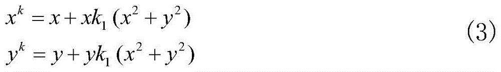
根据相机的径向畸变函数,对畸变系数进行计算,其公式如下:According to the radial distortion function of the camera, the distortion coefficient is calculated, and the formula is as follows:

其中,xk,yk分别是实际径像畸变情况下的归一化坐标,x,y代表理想无畸变时的归一化坐标,k1为图像径向畸变系数,基于相机标定参数所求解的理想归一化坐标和图像提取的归一化坐标,以公式(3)为目标函数,采用LM优化方法求解图像畸变系数k1;Among them, x k , y k are the normalized coordinates in the case of actual radial image distortion, x, y represent the normalized coordinates when ideal without distortion, k 1 is the image radial distortion coefficient, which is solved based on the camera calibration parameters The ideal normalized coordinates of , and the normalized coordinates of image extraction, take formula (3) as the objective function, and use the LM optimization method to solve the image distortion coefficient k 1 ;
然后,基于空间两个固定放置的标定右相机的平面靶标3和标定左相机的平面靶标2对左、右相机1、4进行角度调整,即左右相机的相机平面与对其对应的平面靶标平行,其旋转矩阵R满足:Then, the left and

其中,a,b,c,d为旋转矩阵参数,ε为无限接近于0的值,|γ|无线接近于1;Among them, a, b, c, d are rotation matrix parameters, ε is a value that is infinitely close to 0, and |γ| is infinitely close to 1;
然后进行左右相机的结构参数标定,即实现左右相机之间旋转平移矩阵的计算,其计算公式如下:Then, the structural parameters of the left and right cameras are calibrated, that is, the calculation of the rotation and translation matrix between the left and right cameras is realized. The calculation formula is as follows:

其中,

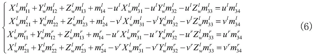
再进行特征提取与初值重建,采用灰度重心法提取被测目标的特征中心,左右相机提取的特征坐标分别为pl(ul,vl),pr(ur,vr);以左相机摄像机为世界坐标系,将左右所提取的特征点进行三维重建,其公式如下:Then perform feature extraction and initial value reconstruction, and use the gray center of gravity method to extract the feature center of the measured target. The feature coordinates extracted by the left and right cameras are p l (u l , v l ), p r (u r , v r ); Taking the left camera as the world coordinate system, the feature points extracted from the left and right are reconstructed in 3D. The formula is as follows:

其中,


第二步基于三维畸变的参数计算The second step is based on the parameter calculation of 3D distortion
基于双目相机标定结果计算合焦位置的三维畸变的性质参数,所标定的相机焦距可表示为Cs,合焦位置的深度可表示为:Based on the calibration results of the binocular cameras, the property parameters of the three-dimensional distortion of the in-focus position are calculated. The calibrated camera focal length can be expressed as C s , and the depth of the in-focus position can be expressed as:

其中,Ss为合焦位置的深度,Cs为相机焦距,dpix为平面靶标在图像上的像素长度,dphy为平面靶标的真实物理尺寸,λ为相机的像元尺寸;计算相机的凸透镜焦距F,其计算公式如下:Among them, S s is the depth of the in-focus position, C s is the focal length of the camera, d pix is the pixel length of the flat target on the image, d phy is the real physical size of the flat target, and λ is the pixel size of the camera; The focal length F of the convex lens is calculated as follows:

其中,F为相机的凸透镜焦距,Ss为合焦位置的深度,Cs为相机焦距,将相机平行移动相机位置到S1和S2位置,对相机进行标定,基于公式(8)计算这两个位置的深度值S1和S2,并基于公式(3)计算在该两个位置畸变系数

第三步畸变补偿与高精度重建The third step of distortion compensation and high-precision reconstruction
畸变补偿值计算,基于初值计算结果和参数计算结果,计算左右相机的三维空间畸变量,其中左相机的畸变量为:Distortion compensation value calculation, based on the initial value calculation results and parameter calculation results, calculate the three-dimensional spatial distortion of the left and right cameras, where the distortion of the left camera is:

其中,δl为左图像测量点的畸变量,


其中,δr为右图像测量点的畸变量,


补偿与重建,基于所求的畸变量,对被测点进行补偿,左图像补偿后的被测点图像坐标为:Compensation and reconstruction, based on the required distortion amount, the measured point is compensated, and the image coordinates of the measured point after the left image compensation are:

其中,ul和vl分别为被测点提取图像行坐标和列坐标,δl为左图像测量点的畸变量,


其中,ur和vr分别为被测点提取图像行坐标和列坐标,δr为右图像测量点的畸变量,

本发明的有益效果是该方法通过引入三维畸变修正函数对视觉重建的结果进行补偿优化,提高被测物在空间的测量精度。该方法有益效果是重建精度高,可补偿双目视觉的三维畸变,实现具有大曲率大尺寸零件形面重建,提高双目视觉的三维重建精度。该方法重建精度高,可补偿双目视觉的三维畸变,实现具有大曲率大尺寸零件形面重建,提高双目视觉的三维重建精度。The beneficial effect of the present invention is that the method compensates and optimizes the result of visual reconstruction by introducing a three-dimensional distortion correction function, thereby improving the measurement accuracy of the measured object in space. The beneficial effect of the method is that the reconstruction accuracy is high, the three-dimensional distortion of binocular vision can be compensated, the shape and surface reconstruction of parts with large curvature and large size can be realized, and the three-dimensional reconstruction accuracy of binocular vision can be improved. The method has high reconstruction accuracy, can compensate the three-dimensional distortion of binocular vision, realize the shape and surface reconstruction of large-sized parts with large curvature, and improve the three-dimensional reconstruction accuracy of binocular vision.
附图说明Description of drawings
图1为测量系统的示意图。其中,1-左相机,2-标定左相机的平面靶标,3-标定右相机的平面靶标,4-右相机,5-电控平移旋转平台,Ow-Xw,Yw,Zw是全局世界坐标系,

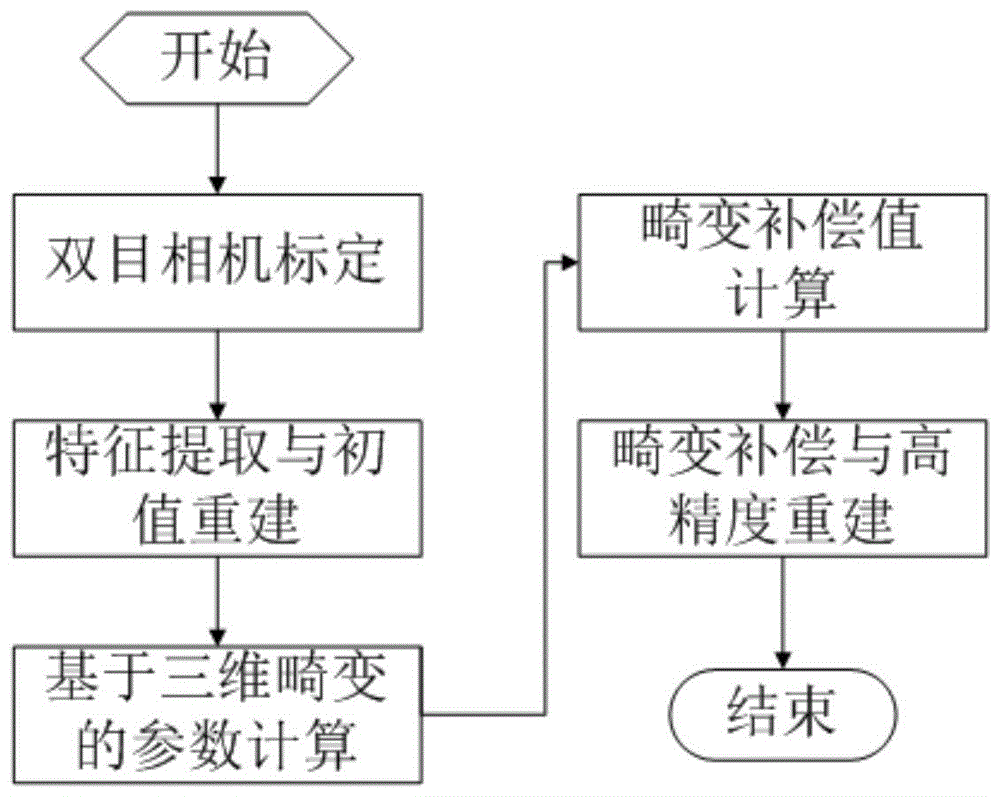
图2为虑及三维畸变的双目视觉重建方法流程图。FIG. 2 is a flowchart of a binocular vision reconstruction method considering three-dimensional distortion.
具体实施方式Detailed ways
以下结合技术方案和附图详细叙述本发明的具体实施方式。The specific embodiments of the present invention are described in detail below with reference to the technical solutions and the accompanying drawings.
图1为测量系统的示意图,如图所示,实施例中,本发明采用分别配置高分辨率双目相机采集二维平面靶标信息,通过电控平移旋转平台5控制二维平面靶标的移动进行双目相机标定。双目视觉系统中相机型号为vieworksVC-12MC-M/C 65摄像机,分辨率:4096×3072,图像传感器:CMOS,帧率:全画幅,最高64.3fps,重量:420g。镜头型号为EF16-35mmf/2.8LIIUSM,参数如下所示,镜头焦距:f=16-35,APS焦距:25.5-52.5,光圈:F2.8,镜头尺寸:82×106。拍摄条件如下:图片像素为4096×3072。旋转电控平台采用卓立汉光的电控旋转平台RAK350,其步距角为1.8度,转角重复精度小于0.003度。电控平移平台采用卓立汉光的电控平移平台UKSA200,重复定位精度小于2μm。Fig. 1 is the schematic diagram of the measurement system, as shown in the figure, in the embodiment, the present invention adopts the configuration of the high-resolution binocular camera to collect the two-dimensional plane target information, and controls the movement of the two-dimensional plane target through the electronically controlled translation and
图2为虑及三维畸变的双目视觉重建方法流程图,测量方法首先对左右相机分别进行标定,然后通过电控平移旋转平台5分别调整左、右相机1、4平行于标定左相机的平面靶标2和标定右相机的平面靶标3。进而通过两个标定位置将双目相机畸变参数标定,并标定双目相机的结构参数,结合被测物目标的提取结果实现被测物的初始重建。参照附图2,整个过程分为双目相机标定、特征提取与初值重建、基于三维畸变的参数计算、畸变补偿值计算、畸变补偿与高精度重建。方法的具体步骤如下:Figure 2 is a flowchart of the binocular vision reconstruction method considering three-dimensional distortion. The measurement method first calibrates the left and right cameras respectively, and then adjusts the left and
第一步三维重建初值计算The first step is to calculate the initial value of 3D reconstruction
先进行双目相机标定,基于张氏标定方法基于公式(1)实现左、右相机1、4进行标定,其内参数矩阵和畸变系数如表1所示:The binocular camera is calibrated first, and the left and
表1Table 1
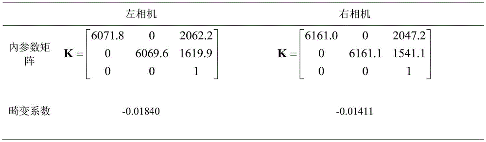
然后,利用电控平移旋转平台5分别调整左、右相机1、4,根据公式(4)使左、右相机1、4分别平行于标定左相机的平面靶标2和标定右相机的平面靶标3。然后进行左右相机的结构参数标定,根据公式(5)实现左右相机的结构参数计算。Then, the left and
进行特征提取与初值重建,采用灰度重心法提取被测目标的特征中心,基于公式(6)实现被测点的初值重建。Feature extraction and initial value reconstruction are carried out, and the gray centroid method is used to extract the feature center of the measured target, and the initial value reconstruction of the measured point is realized based on formula (6).
第二步基于三维畸变的参数计算The second step is based on the parameter calculation of 3D distortion
基于双目相机标定结果计算合焦位置的三维畸变的性质参数,所标定的内参数结果可计算相机焦距,并基于公式(7)计算合焦位置深度,根据公式(8)计算相机的凸透镜焦距,将相机分别平行移动相机位置到S1和S2位置,对相机进行标定,基于公式(7)计算这两个位置的深度值S1和S2,并基于公式(3)计算在该两个位置畸变系数

第三步畸变补偿与高精度重建The third step of distortion compensation and high-precision reconstruction
畸变补偿值计算,基于初值计算结果和参数计算结果,根据公式(9)和公式(10)分别计算左、右相机1、4的三维空间畸变量。Distortion compensation value calculation, based on the initial value calculation result and the parameter calculation result, according to formula (9) and formula (10) to calculate the three-dimensional space distortion value of the left and
补偿与重建,基于所求的畸变量,根据公式(11)和(12)对被测点进行补偿,根据公式(6)实现被测点的高精度重建。双目视觉采集标准长度为350.0172mm的靶尺在空间不同位置采集8次,其平均长度为350.7263,本专利获得的靶尺长度为350.1574mm,提高了测量精度,验证了该提取方法的有效性。Compensation and reconstruction, based on the required distortion amount, the measured points are compensated according to formulas (11) and (12), and the high-precision reconstruction of the measured points is realized according to formula (6). The target ruler with a standard length of 350.0172mm for binocular vision acquisition was collected 8 times at different positions in space, and the average length was 350.7263. The length of the target ruler obtained in this patent is 350.1574mm, which improves the measurement accuracy and verifies the effectiveness of the extraction method. .
Claims (1)


Priority Applications (1)
| Application Number | Priority Date | Filing Date | Title |
|---|---|---|---|
| CN201710496023.XA CN107358631B (en) | 2017-06-27 | 2017-06-27 | A Binocular Vision Reconstruction Method Considering 3D Distortion |
Applications Claiming Priority (1)
| Application Number | Priority Date | Filing Date | Title |
|---|---|---|---|
| CN201710496023.XA CN107358631B (en) | 2017-06-27 | 2017-06-27 | A Binocular Vision Reconstruction Method Considering 3D Distortion |
Publications (2)
| Publication Number | Publication Date |
|---|---|
| CN107358631A CN107358631A (en) | 2017-11-17 |
| CN107358631B true CN107358631B (en) | 2020-05-19 |
Family
ID=60274039
Family Applications (1)
| Application Number | Title | Priority Date | Filing Date |
|---|---|---|---|
| CN201710496023.XA Active CN107358631B (en) | 2017-06-27 | 2017-06-27 | A Binocular Vision Reconstruction Method Considering 3D Distortion |
Country Status (1)
| Country | Link |
|---|---|
| CN (1) | CN107358631B (en) |
Families Citing this family (27)
| Publication number | Priority date | Publication date | Assignee | Title |
|---|---|---|---|---|
| CN108010085B (en) * | 2017-11-30 | 2019-12-31 | 西南科技大学 | Target recognition method based on binocular visible light camera and thermal infrared camera |
| CN109978986B (en) * | 2017-12-28 | 2023-03-07 | 深圳市优必选科技有限公司 | Three-dimensional model reconstruction method and device, storage medium and terminal equipment |
| CN108680227B (en) * | 2018-07-27 | 2023-12-08 | 中国石油天然气集团有限公司 | Binocular vision material level meter, application method thereof and material level measuring method |
| CN109272570B (en) * | 2018-08-16 | 2022-10-25 | 合肥工业大学 | Space point three-dimensional coordinate solving method based on stereoscopic vision mathematical model |
| CN109003312B (en) * | 2018-08-24 | 2022-01-28 | 重庆邮电大学 | Camera calibration method based on nonlinear optimization |
| CN109360269B (en) * | 2018-09-30 | 2022-12-06 | 国网黑龙江省电力有限公司电力科学研究院 | Ground three-dimensional plane reconstruction method based on computer vision |
| CN109741393B (en) * | 2018-12-04 | 2023-06-09 | 上海大学 | Diameter measurement and center point location method of Agaricus bisporus |
| CN109636903B (en) * | 2018-12-24 | 2020-09-15 | 华南理工大学 | A dither-based binocular 3D reconstruction method |
| CN110345921B (en) * | 2019-06-12 | 2020-06-26 | 中国农业大学 | Stereo visual field vision measurement and vertical axis aberration and axial aberration correction method and system |
| CN110989664A (en) * | 2019-11-29 | 2020-04-10 | 北京特种机械研究所 | Unmanned aerial vehicle night plant protection method based on multi-view vision |
| CN111080714B (en) * | 2019-12-13 | 2023-05-16 | 太原理工大学 | A Calibration Method of Parallel Binocular Camera Based on 3D Reconstruction |
| CN110992431B (en) * | 2019-12-16 | 2023-04-18 | 电子科技大学 | Combined three-dimensional reconstruction method for binocular endoscope soft tissue image |
| CN111243018A (en) * | 2019-12-31 | 2020-06-05 | 北京航空航天大学 | Method and system for automatically performing mole removal surgery |
| CN112237416A (en) * | 2020-09-10 | 2021-01-19 | 北京信息科技大学 | Fundus multi-mode imaging system calibration method based on retinal surface blood vessel characteristics |
| CN112465913A (en) * | 2020-11-18 | 2021-03-09 | 广东博智林机器人有限公司 | Binocular camera-based correction method and device |
| CN112634375B (en) * | 2020-12-21 | 2022-08-05 | 杭州东信北邮信息技术有限公司 | Plane calibration and three-dimensional reconstruction method in AI intelligent detection |
| US20220264072A1 (en) * | 2021-02-12 | 2022-08-18 | Sony Group Corporation | Auto-calibrating n-configuration volumetric camera capture array |
| CN112967348A (en) * | 2021-04-01 | 2021-06-15 | 深圳大学 | Three-dimensional reconstruction method based on one-dimensional scanning structured light system and related components thereof |
| CN113160393B (en) * | 2021-05-14 | 2023-08-04 | 深圳大学 | High-precision three-dimensional reconstruction method, device and related components based on large depth of field |
| CN113513981B (en) * | 2021-06-15 | 2022-10-25 | 西安交通大学 | Multi-target parallel measurement method, system, equipment and storage medium based on binocular stereo vision |
| CN114018214A (en) * | 2021-10-18 | 2022-02-08 | 武汉理工大学 | Marker binocular sub-pixel distance measurement method based on hardware acceleration system |
| CN114359365B (en) * | 2022-01-11 | 2024-02-20 | 合肥工业大学 | A convergent binocular vision measurement method with high resolution |
| CN114705216B (en) * | 2022-02-23 | 2024-08-23 | 天津大学 | Secondary calibration method for three-dimensional vision measurement system |
| CN114842091B (en) * | 2022-04-29 | 2023-05-23 | 广东工业大学 | Binocular egg size assembly line measuring method |
| CN115112043B (en) * | 2022-05-20 | 2025-04-29 | 天津大学 | A parallel plate refraction imaging binocular vision three-dimensional measurement method |
| CN119011817B (en) * | 2024-10-24 | 2025-01-24 | 中国特种设备检测研究院 | A focal length calibration method and system for large-scale binocular vision measurement cameras |
| CN119757793B (en) * | 2024-12-18 | 2025-09-30 | 武汉大学 | Glacier monitoring method and system based on visual binocular three-dimensional reconstruction |
Citations (1)
| Publication number | Priority date | Publication date | Assignee | Title |
|---|---|---|---|---|
| CN105698699A (en) * | 2016-01-26 | 2016-06-22 | 大连理工大学 | A binocular visual sense measurement method based on time rotating shaft constraint |
Family Cites Families (1)
| Publication number | Priority date | Publication date | Assignee | Title |
|---|---|---|---|---|
| US10750153B2 (en) * | 2014-09-22 | 2020-08-18 | Samsung Electronics Company, Ltd. | Camera system for three-dimensional video |
-
2017
- 2017-06-27 CN CN201710496023.XA patent/CN107358631B/en active Active
Patent Citations (1)
| Publication number | Priority date | Publication date | Assignee | Title |
|---|---|---|---|---|
| CN105698699A (en) * | 2016-01-26 | 2016-06-22 | 大连理工大学 | A binocular visual sense measurement method based on time rotating shaft constraint |
Non-Patent Citations (4)
| Title |
|---|
| Accurate Depth Dependent Lens Distortion Models: An Application to Planar View Scenarios;Luis Alvarez et.al;《J Math Imaging Vis》;20111231;第75-85页 * |
| High-precision binocular measuring method considering three-dimensional distortion;Yang Zhang et.al;《Proc. SPIE 10710》;20180305;第1-6页 * |
| Modelling and calibration of depth-dependent distortion for large depth visual measurement cameras;PENG SUN et.al;《OPTICS EXPRESS》;20170501;第25卷(第9期);第1-14页 * |
| 适用于动态对焦的高精度灵活标定方法;周佳立 等;《模式识别与人工智能》;20160630;第29卷(第6期);第481-491页 * |
Also Published As
| Publication number | Publication date |
|---|---|
| CN107358631A (en) | 2017-11-17 |
Similar Documents
| Publication | Publication Date | Title |
|---|---|---|
| CN107358631B (en) | A Binocular Vision Reconstruction Method Considering 3D Distortion | |
| CN107144241B (en) | A kind of binocular vision high-precision measuring method based on depth of field compensation | |
| CN106981083B (en) | The substep scaling method of Binocular Stereo Vision System camera parameters | |
| CN104851104B (en) | Using the flexible big view calibration method of target high speed camera close shot | |
| CN110378969B (en) | Convergent binocular camera calibration method based on 3D geometric constraint | |
| CN107367229B (en) | Free binocular stereo vision rotating shaft parameter calibration method | |
| CN102364299B (en) | Calibration technology for multiple structured light projected three-dimensional profile measuring heads | |
| CN102221331B (en) | Measuring method based on asymmetric binocular stereovision technology | |
| CN111667536A (en) | A parameter calibration method based on zoom camera depth estimation | |
| CN107680139B (en) | Universality calibration method of telecentric binocular stereo vision measurement system | |
| CN105139411B (en) | Big visual field camera calibration method based on four sets of conllinear constraint demarcation chis | |
| CN102867304A (en) | Method for establishing relation between scene stereoscopic depth and vision difference in binocular stereoscopic vision system | |
| CN112258583B (en) | Distortion calibration method for close-range image based on equal distortion partition | |
| CN104075688A (en) | Distance measurement method of binocular stereoscopic gazing monitoring system | |
| CN101231750A (en) | A Calibration Method for Binocular Stereo Measuring System | |
| WO2020199439A1 (en) | Single- and dual-camera hybrid measurement-based three-dimensional point cloud computing method | |
| CN109579695B (en) | Part measuring method based on heterogeneous stereoscopic vision | |
| CN114078163B (en) | Accurate calibration method for LiDAR and visible light camera | |
| CN112229323A (en) | Six degrees of freedom measurement method of checkerboard cooperation target based on monocular vision of mobile phone and its application | |
| CN107941153A (en) | A kind of vision system of laser ranging optimization calibration | |
| CN115457141A (en) | Large-view-field three-dimensional digital image correlation system calibration method based on photogrammetry | |
| CN113048888A (en) | Binocular vision-based remote three-dimensional displacement measurement method and system | |
| CN105374067A (en) | Three-dimensional reconstruction method based on PAL cameras and reconstruction system thereof | |
| CN113724337A (en) | Camera dynamic external parameter calibration method and device without depending on holder angle | |
| CN114926538B (en) | External parameter calibration method and device for monocular laser speckle projection system |
Legal Events
| Date | Code | Title | Description |
|---|---|---|---|
| PB01 | Publication | ||
| PB01 | Publication | ||
| SE01 | Entry into force of request for substantive examination | ||
| SE01 | Entry into force of request for substantive examination | ||
| GR01 | Patent grant | ||
| GR01 | Patent grant |