CN109579695B - Part measuring method based on heterogeneous stereoscopic vision - Google Patents
Part measuring method based on heterogeneous stereoscopic vision Download PDFInfo
- Publication number
- CN109579695B CN109579695B CN201811194104.5A CN201811194104A CN109579695B CN 109579695 B CN109579695 B CN 109579695B CN 201811194104 A CN201811194104 A CN 201811194104A CN 109579695 B CN109579695 B CN 109579695B
- Authority
- CN
- China
- Prior art keywords
- formula
- image
- telecentric
- camera
- industrial camera
- Prior art date
- Legal status (The legal status is an assumption and is not a legal conclusion. Google has not performed a legal analysis and makes no representation as to the accuracy of the status listed.)
- Active
Links
- 230000004438 eyesight Effects 0.000 title claims abstract description 75
- 238000000034 method Methods 0.000 title claims abstract description 47
- 238000005259 measurement Methods 0.000 claims abstract description 55
- 238000003384 imaging method Methods 0.000 claims abstract description 39
- 230000008569 process Effects 0.000 claims description 10
- 238000013178 mathematical model Methods 0.000 claims description 8
- 238000000605 extraction Methods 0.000 claims description 3
- 238000007781 pre-processing Methods 0.000 claims description 3
- 230000009466 transformation Effects 0.000 claims description 3
- NAWXUBYGYWOOIX-SFHVURJKSA-N (2s)-2-[[4-[2-(2,4-diaminoquinazolin-6-yl)ethyl]benzoyl]amino]-4-methylidenepentanedioic acid Chemical compound C1=CC2=NC(N)=NC(N)=C2C=C1CCC1=CC=C(C(=O)N[C@@H](CC(=C)C(O)=O)C(O)=O)C=C1 NAWXUBYGYWOOIX-SFHVURJKSA-N 0.000 claims 2
- 150000001875 compounds Chemical class 0.000 claims 1
- 238000000691 measurement method Methods 0.000 abstract description 8
- 238000004519 manufacturing process Methods 0.000 abstract description 3
- 230000003287 optical effect Effects 0.000 abstract description 3
- 238000012545 processing Methods 0.000 abstract description 3
- 230000000694 effects Effects 0.000 abstract description 2
- 238000005516 engineering process Methods 0.000 description 8
- 238000010586 diagram Methods 0.000 description 5
- 238000004422 calculation algorithm Methods 0.000 description 4
- 238000011160 research Methods 0.000 description 3
- 230000008859 change Effects 0.000 description 2
- 238000002474 experimental method Methods 0.000 description 2
- 230000004927 fusion Effects 0.000 description 2
- 238000007689 inspection Methods 0.000 description 2
- 238000003909 pattern recognition Methods 0.000 description 2
- 238000002310 reflectometry Methods 0.000 description 2
- 238000012360 testing method Methods 0.000 description 2
- 230000000007 visual effect Effects 0.000 description 2
- 238000004458 analytical method Methods 0.000 description 1
- 238000004364 calculation method Methods 0.000 description 1
- 238000012937 correction Methods 0.000 description 1
- 238000000354 decomposition reaction Methods 0.000 description 1
- 238000001514 detection method Methods 0.000 description 1
- 238000011161 development Methods 0.000 description 1
- 238000005286 illumination Methods 0.000 description 1
- 238000009434 installation Methods 0.000 description 1
- 238000012986 modification Methods 0.000 description 1
- 230000004048 modification Effects 0.000 description 1
- 235000001968 nicotinic acid Nutrition 0.000 description 1
- 238000003908 quality control method Methods 0.000 description 1
- 238000011084 recovery Methods 0.000 description 1
- 230000004044 response Effects 0.000 description 1
- 230000000717 retained effect Effects 0.000 description 1
- 238000012876 topography Methods 0.000 description 1
- 238000013519 translation Methods 0.000 description 1
Images


Classifications
-
- G—PHYSICS
- G01—MEASURING; TESTING
- G01B—MEASURING LENGTH, THICKNESS OR SIMILAR LINEAR DIMENSIONS; MEASURING ANGLES; MEASURING AREAS; MEASURING IRREGULARITIES OF SURFACES OR CONTOURS
- G01B11/00—Measuring arrangements characterised by the use of optical techniques
-
- G—PHYSICS
- G01—MEASURING; TESTING
- G01B—MEASURING LENGTH, THICKNESS OR SIMILAR LINEAR DIMENSIONS; MEASURING ANGLES; MEASURING AREAS; MEASURING IRREGULARITIES OF SURFACES OR CONTOURS
- G01B11/00—Measuring arrangements characterised by the use of optical techniques
- G01B11/002—Measuring arrangements characterised by the use of optical techniques for measuring two or more coordinates
Landscapes
- Physics & Mathematics (AREA)
- General Physics & Mathematics (AREA)
- Length Measuring Devices By Optical Means (AREA)
Abstract
本发明提出的一种基于异构立体视觉的零件测量方法,该测量方法采用了1个远心工业相机和2个普通工业相机,并对相机拍摄的图像进行相关处理,使双目立体视觉和单目远心视觉有效结合,通过远心成像补偿普通光学系统的原理性误差,融合双目视觉的优点和远心视觉测量精度高的优点于一体,解决生产现场三维非接触式测量精度低的难题,具有数据可信度高,测量结果可靠的技术效果。

The invention proposes a method for measuring parts based on heterogeneous stereo vision. The measurement method adopts one telecentric industrial camera and two ordinary industrial cameras, and performs correlation processing on the images captured by the cameras, so that the binocular stereo vision and the The monocular telecentric vision is effectively combined, and the principle error of the ordinary optical system is compensated by telecentric imaging, and the advantages of binocular vision and the high measurement accuracy of telecentric vision are integrated into one, so as to solve the problem of low 3D non-contact measurement accuracy on the production site. It has the technical effect of high data reliability and reliable measurement results.
Description
技术领域technical field
本发明涉及零件尺寸测量领域,尤其涉及一种基于异构立体视觉的零件测量方法。The invention relates to the field of part size measurement, in particular to a part measurement method based on heterogeneous stereo vision.
背景技术Background technique
基于机器视觉的零件检测研究从20世纪90年开始兴起,目前逐渐进入各工业领域,测量手段和方法也得到了快速发展。机器视觉就是用机器代替人眼来做测量和判断,通过图像摄取装置CMOS或者CCD将被摄取目标转换成图像信号,传送给专用的图像处理系统,根据像素分布和亮度、颜色等信息,转变成数字化信号;图像系统对这些信号进行各种运算来抽取目标的特征,进而根据判别的结果来控制现场的设备动作。The research on parts inspection based on machine vision began to emerge in the 1990s, and now it has gradually entered various industrial fields, and the measurement methods and methods have also developed rapidly. Machine vision is to use machines instead of human eyes to make measurements and judgments. The image capture device CMOS or CCD converts the captured target into an image signal, and transmits it to a dedicated image processing system. According to pixel distribution, brightness, color and other information, it is converted into an image signal. Digitized signals; the image system performs various operations on these signals to extract the characteristics of the target, and then controls the on-site equipment actions according to the results of the discrimination.
现有技术1:Prior art 1:
受到人类双眼通过视差原理感知环境深度的启发,双目立体视觉测量系统从空间中两个点同时观察被测零件(图1所示),获取被测零件在不同视角下的两幅图像,根据两幅图像之间像素的配准关系,通过三角测量原理计算出像素之间的位置偏差,解得三维空间中任意点的深度信息,最终重建被测零件的三维形貌,进行零件多要素测量。Inspired by the human eyes perceiving the depth of the environment through the principle of parallax, the binocular stereo vision measurement system simultaneously observes the measured part from two points in space (as shown in Figure 1), and obtains two images of the measured part under different viewing angles. The registration relationship between the pixels between the two images, the positional deviation between the pixels is calculated by the principle of triangulation, the depth information of any point in the three-dimensional space is solved, and finally the three-dimensional topography of the measured part is reconstructed, and the multi-element measurement of the part is carried out. .
针对阶梯轴测量问题,长春工业大学吴翔建立了一套双目视觉测量系统,可以对被测零件的多个要素进行测量。实验结果表明,该双目测量系统的最小和最大测量误差分别为0.1mm和0.9mm(吴翔.基于双目视觉的零件尺寸测量系统关键技术研究[D].长春:长春工业大学,2017.)。武汉科技大学张俊勇等提出了一种基于双目视觉的零件多尺寸的测量方法及系统,通过标定、极线校正、极线约束匹配以及三维拟合、三维重建等一系列过程实现被测零件多要素三维测量(张俊勇,伍世虔,徐历洪.一种基于双目视觉的零件多尺寸的测量方法及系统:中国,CN107588721A[P].2018.01.16.)。北京航空航天大学赵剡等着眼狭窄空间目标三维测量,提出了一种狭窄空间双目视觉测量定位装置及方法,(赵剡,苏庆华,吴发林,杨奎,张少辰.一种狭窄空间双目视觉测量定位装置及方法:中国,ZL201210191014.7[P].2012.11.05.)In response to the measurement of the stepped axis, Wu Xiang of Changchun University of Technology established a set of binocular vision measurement system, which can measure multiple elements of the measured part. The experimental results show that the minimum and maximum measurement errors of the binocular measurement system are 0.1mm and 0.9mm respectively (Wu Xiang. Research on key technologies of part size measurement system based on binocular vision [D]. Changchun: Changchun University of Technology, 2017. ). Zhang Junyong of Wuhan University of Science and Technology proposed a multi-dimension measurement method and system for parts based on binocular vision. Through a series of processes such as calibration, epipolar correction, epipolar constraint matching, 3D fitting, and 3D reconstruction, the measured parts are multi-dimensional. Three-dimensional measurement of elements (Zhang Junyong, Wu Shiqian, Xu Lihong. A multi-dimension measurement method and system for parts based on binocular vision: China, CN107588721A[P]. 2018.01.16.). Zhao Yan of Beihang University, etc. focused on the three-dimensional measurement of narrow space targets, and proposed a narrow space binocular vision measurement and positioning device and method, (Zhao Yan, Su Qinghua, Wu Falin, Yang Kui, Zhang Shaochen. A narrow space binocular vision measurement Positioning device and method: China, ZL201210191014.7[P].2012.11.05.)
双目视觉测量是基于仿生原理的一种方法,它具有诸多优点,理论上非常适合在制造现场在线、非接触几何精度检验以及质量控制中应用。然而,事实上双目视觉应用不及其它方法,最关键的制约因素是其测量精度,绝大多数双目系统的精度只有亚毫米级。Binocular vision measurement is a method based on the principle of bionics. It has many advantages and is theoretically very suitable for application in on-line, non-contact geometric accuracy inspection and quality control in manufacturing sites. However, in fact, the application of binocular vision is not as good as that of other methods, and the most critical constraint is its measurement accuracy. The accuracy of most binocular systems is only sub-millimeter level.
现有技术2:Prior art 2:
结构光视觉测量的理论基础是激光三角测距原理。通过向被测零件投射空间数学模型已知的结构光源,机器视觉系统对零件及结构光投影成像(图2所示),联立结构光的空间数学模型和机器视觉系统成像数学模型,经求解即可得到恢复深度信息。光线投影模式有光线、平面、曲面及光束四种,因此,常见结构光视觉测量系统也有四种类型。The theoretical basis of structured light vision measurement is the principle of laser triangulation. By projecting the structural light source known by the spatial mathematical model to the measured part, the machine vision system projects the image of the part and the structured light (as shown in Figure 2), and the spatial mathematical model of the structured light and the imaging mathematical model of the machine vision system are simultaneously solved. The recovery depth information can be obtained. There are four types of light projection modes: light, plane, curved surface and beam. Therefore, there are also four types of common structured light vision measurement systems.
哈尔滨工业大学熊伟男组建了一套结构光视觉测量系统,当物距为250mm时,该系统的测量范围不小于200mm×200mm。利用该系统对厚度和宽度分别为8.845mm和20.000mm的标准量块进行重复测量。在厚度测量实验中,最大和最小测量误差分别是50μm和30μm;在宽度测量实验中,最大和最小测量误差分别是50μm和18μm(熊伟男.三维结构光视觉测量设备研制[D].哈尔滨:哈尔滨工业大学,2017.)。湖北工业大学张从鹏等发明了一种用于零件倒角测量的方法及其装置,该方法主要包括平面模型法标定结构光视觉系统、特征图像采集及预处理、特征提取及特征参数计算等过程,具有精度高、适应性高和效率高的应用特点(张从鹏,侯波,曹文政,鲁磊,任世瑜.一种基于结构光视觉的零件倒角测量方法与装置:中国,CN105783786A[P].2016.07.20.)。黑龙江科技大学何万涛等发明的结构光测量方法及其装置则重点解决高反射率零件难以测量的问题(何万涛,郭延艳,车向前,等.一种用于高反射率零件的面结构光三维测量装置与方法:中国,ZL201310717211.2[P].2016.09.07.)。吉林大学谭庆昌等利用结构光视觉系统测量轴类零件径向跳动误差,在建立径向跳动误差结构光视觉模型基础上,分别通过张正友平面两步标定法和模板匹配法对视觉传感器和结构光进行了标定,再通过测量模型求解出结构光与零件表面交点的空间坐标(谭庆昌,包昊菁,张雅超,等.基于结构光视觉的轴类零件径向跳动误差在线测量方法:中国,CN107101582A[P].2017.08.29.)。Xiong Weinan of Harbin Institute of Technology established a structured light vision measurement system. When the object distance is 250mm, the measurement range of the system is not less than 200mm×200mm. The system was used to perform repeated measurements on standard gauge blocks with thickness and width of 8.845mm and 20.000mm, respectively. In the thickness measurement experiment, the maximum and minimum measurement errors are 50 μm and 30 μm, respectively; in the width measurement experiment, the maximum and minimum measurement errors are 50 μm and 18 μm, respectively (Xiong Weinan. Development of 3D Structured Light Vision Measurement Equipment [D]. Harbin: Harbin University of Technology, 2017.). Zhang Congpeng of Hubei University of Technology, etc. invented a method and device for measuring the chamfer of parts. The method mainly includes the process of calibrating the structured light vision system by the plane model method, feature image acquisition and preprocessing, feature extraction and feature parameter calculation. It has the application characteristics of high precision, high adaptability and high efficiency (Zhang Congpeng, Hou Bo, Cao Wenzheng, Lu Lei, Ren Shiyu. A method and device for measuring the chamfer of parts based on structured light vision: China, CN105783786A[P]. 2016.07 .20.). The structured light measurement method and its device invented by He Wantao of Heilongjiang University of Science and Technology focus on solving the problem that high reflectivity parts are difficult to measure (He Wantao, Guo Yanyan, Che Xiangqian, etc. A three-dimensional measurement of surface structured light for high reflectivity parts Apparatus and Methods: China, ZL201310717211.2[P].2016.09.07.). Tan Qingchang et al. of Jilin University used a structured light vision system to measure the radial runout error of shaft parts. Based on the establishment of a structured light vision model of radial runout error, the two-step calibration method of Zhang Zhengyou plane and the template matching method were used to measure the visual sensor and structured light. After calibration, the spatial coordinates of the intersection of the structured light and the surface of the part are solved through the measurement model (Tan Qingchang, Bao Haojing, Zhang Yachao, et al. On-line measurement method of radial runout error of shaft parts based on structured light vision: China, CN107101582A [P ].2017.08.29.).
结构光视觉及其改进方法均利用已知位姿的光源进行主动照明,只需要在一幅图像上提取特征即可恢复图像深度信息,避免了双目视觉中的左、右两幅图像配准难题,因此,结构光视觉的测量精度相比双目视觉已有明显地提高。尽管如此,结构光视觉的测量精度依然还停留在丝级。而且,相比双目视觉,结构光视觉的点云密度有非常明显地降低,这将不利于零件微小特征的三维重建。此外,还有结构光的标定问题和高性能激光器及其成本问题等还有待继续研究。Structured light vision and its improved methods both use light sources with known poses for active illumination, and only need to extract features from one image to restore image depth information, avoiding the registration of left and right images in binocular vision. Therefore, the measurement accuracy of structured light vision has been significantly improved compared with binocular vision. Nevertheless, the measurement accuracy of structured light vision still remains at the silk level. Moreover, compared with binocular vision, the point cloud density of structured light vision is significantly reduced, which is not conducive to the 3D reconstruction of small features of parts. In addition, the calibration of structured light and high-performance lasers and their cost remain to be studied.
现有技术3:Prior art 3:
多目视觉和双目视觉有相同的理论基础与工作原理,通过在原有双目视觉基础上另增加多个成像传感器而组成。多目视觉从空间中三个及以上点同时观察被测零件,获得被测零件在不同视觉下的多幅图像,根据图像之间的配准关系和三角测距原理,从而建立起表征三维空间任意点深度的数学模型,进而可重建被测零件的三维形貌,开展零件多要素测量。相比双目视觉,多目视觉引入了更多的约束条件,理论上具有更高的测量精度。最简单的多目视觉是三目视觉,它在工业中的应用呈现上升趋势。Polyocular vision and binocular vision have the same theoretical basis and working principle, and are formed by adding multiple imaging sensors to the original binocular vision. Multi-eye vision simultaneously observes the measured part from three or more points in the space, and obtains multiple images of the measured part under different visions. The mathematical model of the depth of any point can then reconstruct the three-dimensional appearance of the measured part and carry out multi-element measurement of the part. Compared with binocular vision, multi-eye vision introduces more constraints and theoretically has higher measurement accuracy. The simplest form of multi-eye vision is trinocular vision, and its use in industry is on the rise.
Ye等在双目系统中引入第三台相机,组成三目视觉测量系统,为立体匹配增加更多约束条件,减少双目视觉系统匹配的不确定性,消除干扰信息,有效地提高结果精度(YePan,Li Li,Jin Wei-Qi,Jiang Yu-Tong.Research on imaging ranging algorithm baseon constraint matching of trinocular vision[C].//Proc.SPIE 9301,IPTA 2014:Image Processing and Pattern Recognition.Beijing,China,May 13-15,2014.)。Lu和Shao建立一套三目系统,设计一个球形标定件,通过奇异值分解得到平移和旋转矩阵。结果表明,三目系统相对精度提高到了0.105%,均方根误差为0.026mm,证明了系统的精度和鲁棒性(Lu Rui,Shao Mingwei.Sphere-based calibration method for trinocularvision sensor[J].Opt.Lasers Eng.,2017,90:119-127.)。针对双目视觉测量大幅度摇摆对象精度低的问题,智造未来(北京)机器人系统技术有限公司提出一种基于三目视觉的目标追踪方法及装置(韩业鑫.三目视觉识别追踪装置及方法:中国,CN107507231A[P].2017.12.22.)。Ye et al. introduced a third camera into the binocular system to form a trinocular vision measurement system, adding more constraints for stereo matching, reducing the uncertainty of binocular vision system matching, eliminating interference information, and effectively improving the accuracy of results ( YePan,Li Li,Jin Wei-Qi,Jiang Yu-Tong.Research on imaging ranging algorithm baseon constraint matching of trinocular vision[C].//Proc.SPIE 9301,IPTA 2014:Image Processing and Pattern Recognition.Beijing,China, May 13-15, 2014.). Lu and Shao established a trinocular system, designed a spherical calibration element, and obtained translation and rotation matrices through singular value decomposition. The results show that the relative accuracy of the trinocular system is improved to 0.105%, and the root mean square error is 0.026mm, which proves the accuracy and robustness of the system (Lu Rui, Shao Mingwei. Sphere-based calibration method for trinocularvision sensor[J].Opt . Lasers Eng., 2017, 90:119-127.). Aiming at the problem of low accuracy of binocular vision measurement of large swinging objects, Zhizao Future (Beijing) Robot System Technology Co., Ltd. proposed a target tracking method and device based on trinocular vision (Han Yexin. Trinocular Vision Recognition Tracking Device and Method: China, CN107507231A[P].2017.12.22.).
受多传感融合测量技术的启发,通过在双目系统基础上引入更多成像传感器,组建三目或三目以上的多目视觉系统,它不仅降低了测量不确定度,而且在一定程度上也提高了测量精度。但是,三目系统的精度仍不能满足机械零件高精度测量的需要。究其原因,多目视觉系统中的多台相机都采用小孔成像模型,普通镜头造成的视差、畸变等原理性误差依然无法消除。Inspired by the multi-sensor fusion measurement technology, by introducing more imaging sensors on the basis of the binocular system, a multi-eye vision system with trinocular or more is established, which not only reduces the measurement uncertainty, but also to a certain extent. The measurement accuracy is also improved. However, the accuracy of the trinocular system still cannot meet the needs of high-precision measurement of mechanical parts. The reason is that many cameras in the multi-eye vision system use the pinhole imaging model, and the principle errors such as parallax and distortion caused by ordinary lenses still cannot be eliminated.
发明内容SUMMARY OF THE INVENTION
本发明正是针对现有技术存在的不足,提供了一种基于异构立体视觉的零件测量方法,该方法将双目立体视觉和单目远心视觉有效结合,通过远心成像补偿普通光学系统的原理性误差,融合双目视觉的优点和远心视觉测量精度高的优点于一体,解决生产现场三维非接触式测量精度低的难题。The present invention is aimed at the shortcomings of the prior art, and provides a method for measuring parts based on heterogeneous stereo vision. The method effectively combines binocular stereo vision and monocular telecentric vision, and compensates for ordinary optical systems through telecentric imaging. It integrates the advantages of binocular vision and the advantages of high measurement accuracy of telecentric vision, and solves the problem of low 3D non-contact measurement accuracy on the production site.
本发明所采取的技术方案如下:The technical scheme adopted by the present invention is as follows:
一种基于异构立体视觉的零件测量方法,包括以下步骤:A method for measuring parts based on heterogeneous stereo vision, comprising the following steps:
S1、根据被测零件的尺寸和相机的景深,确定好1号远心工业相机、2号普通工业相机和3号普通工业相机的位置,并保持相机之间的位置关系,对相机进行标定,使相机对被测零件成像,得到左图像、右图像和远心图像;S1. Determine the positions of the No. 1 telecentric industrial camera, No. 2 general industrial camera and No. 3 general industrial camera according to the size of the measured part and the depth of field of the camera, and maintain the positional relationship between the cameras to calibrate the cameras. Make the camera image the part under test to obtain left image, right image and telecentric image;
S2、通过包括图像预处理、特征提取、特征匹配在内的过程,配准“左-右”图像对和“左-右-远心”图像对;S2. Register the "left-right" image pair and the "left-right-telecentric" image pair through a process including image preprocessing, feature extraction, and feature matching;
S3、根据左图像和右图像的配准关系、以及普通工业相机标定的内外参数,构建双目视觉系统数学模型,得到左图像和右图像的特征点的深度信息;S3. According to the registration relationship between the left image and the right image, as well as the internal and external parameters calibrated by ordinary industrial cameras, construct a mathematical model of the binocular vision system, and obtain the depth information of the feature points of the left image and the right image;
S4、对“左-右-远心”图像所拥有的特征点按每2个特征点为一组进行分组,根据S3中得到的深度信息,计算每组2个特征点深度的绝对差值,若绝对差值大于预设阈值,排除该组;S4. Group the feature points possessed by the "left-right-telecentric" image as a group of 2 feature points, and calculate the absolute difference of the depth of each group of 2 feature points according to the depth information obtained in S3, If the absolute difference is greater than the preset threshold, exclude the group;
S5、将S4中保留下来的特征点向远心工业相机的焦平面投影,计算每组内的2个投影点沿水平和竖直两个坐标方向的距离;S5. Project the feature points retained in S4 to the focal plane of the telecentric industrial camera, and calculate the distances between the two projection points in each group along the horizontal and vertical coordinate directions;
S6、根据S5中所得到的距离,修正S1中标定的内、外参数,根据S2中得到的左图像和右图像的配准关系、以及修正后的普通工业相机内外参数,重构重双目视觉系统数学模型,得到更新后的左图像和右图像的特征点的深度信息;S6. According to the distance obtained in S5, correct the internal and external parameters calibrated in S1, and reconstruct the double binocular according to the registration relationship between the left image and the right image obtained in S2 and the corrected internal and external parameters of the ordinary industrial camera. Mathematical model of the visual system to obtain the updated depth information of the feature points of the left and right images;
S7、根据更新后的深度信息,构建被测零件的三维模型,进行三维特征识别,提取被测零件轮廓要素,从而实现被测零件几何特征的测量。S7. According to the updated depth information, construct a three-dimensional model of the measured part, carry out three-dimensional feature recognition, and extract outline elements of the measured part, so as to realize the measurement of the geometric features of the measured part.
优选地,在S1中,采用如下方式对远心工业相机进行标定:使远心相机对已知尺寸的标定件成像,获取标定件的实际尺寸与像素尺寸的比值,得到远心相机的当量像素。Preferably, in S1, the telecentric industrial camera is calibrated in the following manner: the telecentric camera is made to image a calibration piece of known size, the ratio of the actual size of the calibration piece to the pixel size is obtained, and the equivalent pixel of the telecentric camera is obtained. .
优选地,在S1中,采用如下方式对普通工业相机进行标定:在普通工业相机安装后,采用张正友平面标定法对普通工业相机进行标定,基于标定结果确定普通工业相机的内外参数。Preferably, in S1, the ordinary industrial camera is calibrated in the following manner: after the ordinary industrial camera is installed, the ordinary industrial camera is calibrated by the Zhang Zhengyou plane calibration method, and the internal and external parameters of the ordinary industrial camera are determined based on the calibration result.
优选地,在S4中,提取左图像、右图像和远心图像中的特征点,找到左图像和右图像的同名特征,测量两个特征点之间的欧式距离,若绝对差值大于预设阈值,剔除该组特征点。Preferably, in S4, extract the feature points in the left image, the right image and the telecentric image, find the feature with the same name of the left image and the right image, measure the Euclidean distance between the two feature points, if the absolute difference is greater than the preset Threshold to remove this group of feature points.
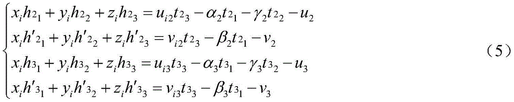
优选地,零件测量方法的函数过程如下:Preferably, the functional process of the part measurement method is as follows:
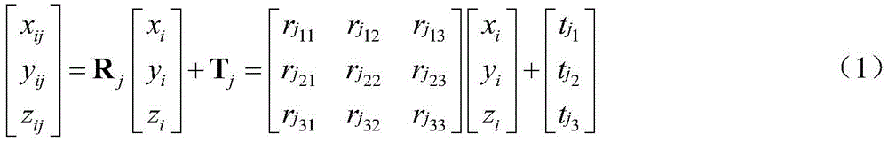
建立世界坐标系ow-xwywzw,1号远心工业相机的相机坐标系o1c-x1cy1cz1c,2号普通工业相机的相机坐标系o2c-x2cy2cz2c,3号普通工业相机的相机坐标系o3c-x3cy3cz3c;Establish the world coordinate system o w -x w y w z w , the camera coordinate system of the No. 1 telecentric industrial camera o 1c -x 1c y 1c z 1c , the camera coordinate system of the No. 2 ordinary industrial camera o 2c -x 2c y 2c z 2c , the camera coordinate system of the No. 3 ordinary industrial camera o 3c -x 3c y 3c z 3c ;
被测零件上的某个点Pi世界坐标为(xi,yi,zi),该点在1号、2号以及3号相机坐标系下的坐标分别为:The world coordinates of a point P i on the measured part are (x i , y i , z i ), and the coordinates of this point in the camera coordinate system No. 1, No. 2 and No. 3 are:
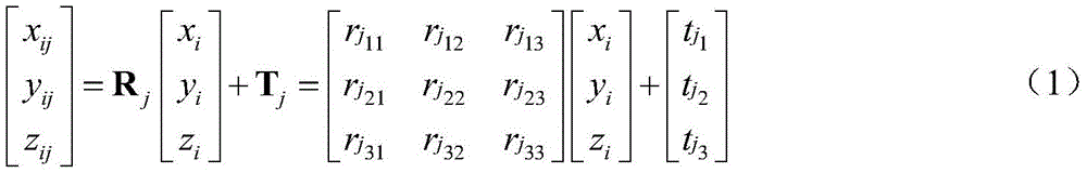
式中Rj和Tj表示从世界坐标系到第j(j=1,2,3)个成像系统相机坐标系的坐标变换关系,也称为成像系统外参数;where R j and T j represent the coordinate transformation relationship from the world coordinate system to the jth (j=1, 2, 3) imaging system camera coordinate system, also known as imaging system external parameters;
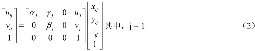
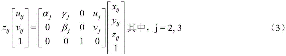
用
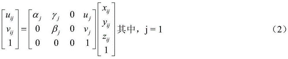

式中αj、βj、γj、uj及vj是成像系统内参数,(uij,vij)是像点Pij的像素坐标;where α j , β j , γ j , u j and v j are the internal parameters of the imaging system, and (u ij , v ij ) are the pixel coordinates of the image point P ij ;
对1号、2号以及3号成像系统采集到的图像进行特征点提取,并建立相应的特征点结合集合A1、A2及A3;Extracting feature points from the images collected by the imaging systems No. 1, No. 2 and No. 3, and establishing corresponding feature point combination sets A 1 , A 2 and A 3 ;
从集合A2中任取一个元素a2s,
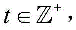
从集合B2中任取一个元素b2s,

将式(1)和式(3)联立并改写成如下形式,将待求的空间坐标写到方程式的左边:Combine equations (1) and (3) and rewrite them into the following form, and write the spatial coordinates to be found on the left side of the equation:
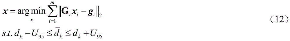
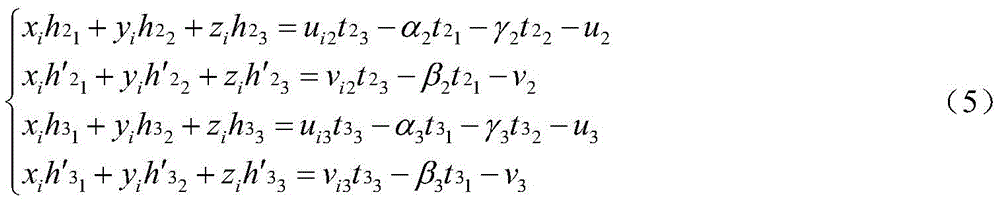
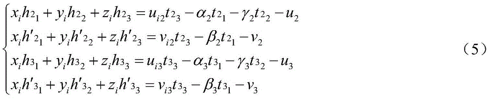
式中
令m=|C2|,c2i∈C2,c3i∈C3,i=1,2,…,m,特征点c2i的像素坐标是(ui2,vi2),即j=2;特征点c3i的像素坐标是(ui3,vi3),即j=3;将像素坐标代入到式(4)、hjk及
式(5)中空间坐标(xi,yi,zi)未知,其余参数均已知,改写式(5)成式(6):In formula (5), the spatial coordinates (x i , y i , z i ) are unknown, and the rest of the parameters are known, so formula (5) is rewritten into formula (6):
Gixi=gi (6)G i x i =g i (6)
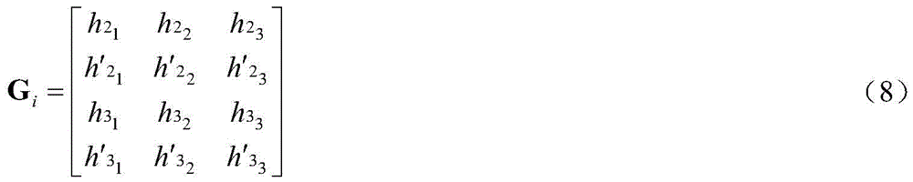
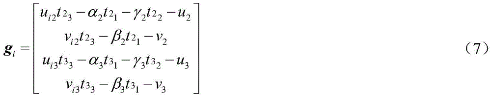
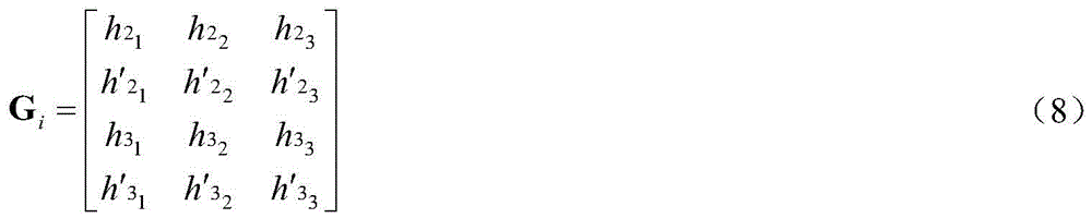
式中xi=[xi,yi,zi]T,gi和Gi分别见式(7)和式(8):In the formula, x i =[x i , y i , z i ] T , and g i and G i are shown in formula (7) and formula (8) respectively:
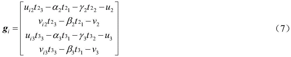
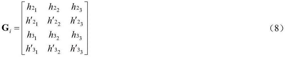
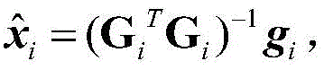
最小二乘法求解式(6)得到


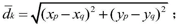
式中,β-和β⊥分别是1号成像系统水平和竖直方向上的当量像素,单位mm/pixel;In the formula, β - and β ⊥ are the equivalent pixels in the horizontal and vertical directions of the No. 1 imaging system, respectively, in mm/pixel;
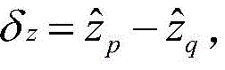
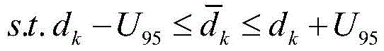
置信水平取95%,记1号成像系统的扩展不确定度为U95,dk的真值

式中,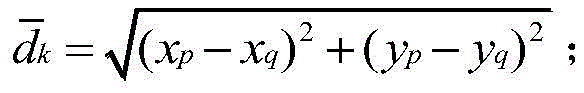
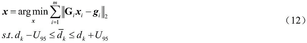
将式(6)等价成式(11)所示的非线性无约束极值问题:Equation (6) is equivalent to the nonlinear unconstrained extreme value problem shown in Equation (11):

双目视觉系统的测量精度可以达到1/10mm,在远心视觉系统的景深范围内,基于以上两点将全部的式(10)作为约束条件,将式(11)变成非线性约束极值问题:The measurement accuracy of the binocular vision system can reach 1/10mm. Within the depth of field of the telecentric vision system, based on the above two points, all equations (10) are used as constraints, and equation (11) is transformed into a nonlinear constraint extreme value question:
以最小二乘法的解作为初值,即


本发明与现有技术相比较,本发明的实施效果如下:The present invention is compared with the prior art, and the implementation effect of the present invention is as follows:
本发明将现有技术一和远心视觉系统有机结合起来,通过多个传感器数据的融合来获得测量结果,增加了系统信息的利用率,增强了数据的可信度,提高了系统的可靠性。The present invention organically combines the
本发明不需要使用高性能的激光光源,既没有激光光源高成本的问题,也没有因结构光间隔运动导致点云密度降低的问题。The present invention does not need to use a high-performance laser light source, neither the problem of high cost of the laser light source nor the problem of reduced point cloud density due to the interval movement of the structured light.
本发明所引入的第三目相机是远心工业相机,它具有放大倍数恒定、无视差、图像畸变小等特点,测量精度较高。The tertiary camera introduced in the present invention is a telecentric industrial camera, which has the characteristics of constant magnification, no parallax, small image distortion, etc., and high measurement accuracy.
附图说明Description of drawings
图1是现有技术1中双目立体视觉系统测量原理图。FIG. 1 is a measurement principle diagram of a binocular stereo vision system in the
图2是现有技术2中线结构光视觉测量原理图。FIG. 2 is a schematic diagram of the
图3是现有技术3中多目视觉系统测量原理图。FIG. 3 is a measurement principle diagram of a polyocular vision system in the
图4是本发明的结构示意图。Figure 4 is a schematic structural diagram of the present invention.
图5是本发明的原理示意图。FIG. 5 is a schematic diagram of the principle of the present invention.
具体实施方式Detailed ways
下面将结合本发明实施例中的附图,对本发明实施例中的技术方案进行清楚、完整性地描述。当然,所描述的实施例只是本发明一部分实施例,而不是全部的实施例。The technical solutions in the embodiments of the present invention will be clearly and completely described below with reference to the accompanying drawings in the embodiments of the present invention. Of course, the described embodiments are only some, but not all, embodiments of the present invention.
参照图4、5,图中:Referring to Figures 4 and 5, in the figure:
1(a):1号远心工业相机;1(a): No. 1 telecentric industrial camera;
2(a):2号普通工业相机;2(a): No. 2 ordinary industrial camera;
3(a):3号普通工业相机;3(a): No. 3 ordinary industrial camera;
1(b):1(a)的像平面;1(b): the image plane of 1(a);
2(b):2(a)的像平面;2(b): the image plane of 2(a);
3(b):3(a)的像平面;3(b): the image plane of 3(a);
4:被测零件;4: Measured parts;
5:被测零件上任意的被测点p;5: Any measured point p on the measured part;
6:被测零件上任意的被测点q;6: Any measured point q on the measured part;
7:被测点P在1(a)中的像点;7: The image point of the measured point P in 1(a);
8:被测点q在1(a)中的像点;8: The image point of the measured point q in 1(a);
9:被测点q在2(b)中的像点;9: The image point of the measured point q in 2(b);
10:被测点P在成像系统3中的像点;10: The image point of the measured point P in the
11:异构立体视觉系统安装基础。11: Installation base of heterogeneous stereo vision systems.
在测量前,根据被测零件的尺寸和相机的景深,确定好1号远心工业相机、2号普通工业相机和3号普通工业相机的位置,并保持相机之间的位置关系,从而建立出如图4所示的三维测量空间,然后对上述三个相机相机进行标定。Before measuring, according to the size of the measured part and the depth of field of the camera, determine the positions of the No. 1 telecentric industrial camera, No. 2 general industrial camera and No. 3 general industrial camera, and maintain the positional relationship between the cameras, so as to establish a The three-dimensional measurement space shown in Figure 4 is then calibrated for the above three cameras.
ow-xwywzw是世界坐标系,o1c-x1cy1cz1c是1号远心工业相机的相机坐标系,o2c-x2cy2cz2c是2号普通工业相机的相机坐标系,o3c-x3cy3cz3c是3号普通工业相机的相机坐标系。o w -x w y w z w is the world coordinate system, o 1c -x 1c y 1c z 1c is the camera coordinate system of the No. 1 telecentric industrial camera, and o 2c -x 2c y 2c z 2c is the No. 2 ordinary industrial camera The camera coordinate system of , o 3c -x 3c y 3c z 3c is the camera coordinate system of the No. 3 general industrial camera.
Pi被测零件上的某个点,它的世界坐标是(xi,yi,zi),该点在1号、2号以及3号相机坐标系下的坐标分别为:For a point on the measured part of P i , its world coordinates are (x i , y i , z i ), and the coordinates of the point in the camera coordinate system No. 1, No. 2 and No. 3 are:

式中Rj和Tj表示从世界坐标系到第j(j=1,2,3)个成像系统相机坐标系的坐标变换关系,也称为成像系统外参数。In the formula, R j and T j represent the coordinate transformation relationship from the world coordinate system to the jth (j=1, 2, 3) imaging system camera coordinate system, which are also called imaging system external parameters.
用

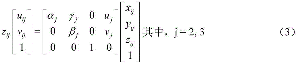
式中αj、βj、γj、uj及vj是成像系统内参数,(uij,vij)是像点
通常,1号远心成像系统并非是通过标定其内、外参数才能进行测量,而是标定其当量像素,也就是通过对已知尺寸的标定件成像,以获得标定件实际尺寸与像素尺寸的比值。2号和3号成像系统的标定问题有多种解决方法,比如张正友平面标定法(Zhang ZhengYou.A Flexible New Technique for Camera Calibration[J].IEEE Transactions onPattern Analysis and Machine Intelligence,2000,22(11):1330-1334.)。现假设三套成像系统均已标定,即1号成像系统的当量像素、2号和3号成像系统的内、外参数均已知。Usually, the No. 1 telecentric imaging system can measure not by calibrating its internal and external parameters, but by calibrating its equivalent pixels, that is, by imaging a calibration part of known size, to obtain the actual size of the calibration part and the pixel size. ratio. There are many solutions to the calibration problem of No. 2 and No. 3 imaging systems, such as Zhang Zhengyou's plane calibration method (Zhang ZhengYou. A Flexible New Technique for Camera Calibration [J]. IEEE Transactions on Pattern Analysis and Machine Intelligence, 2000, 22(11) : 1330-1334.). Now it is assumed that the three imaging systems have been calibrated, that is, the equivalent pixels of the No. 1 imaging system, and the internal and external parameters of the No. 2 and No. 3 imaging systems are known.
使3个相机对被测零件成像,得到左图像、右图像和远心图像,假定1号、2号以及3号成像系统采集到的图像分别为image1、image2和image3。现对image1、image2及image3进行特征点提取并建立相应的特征描述子,比如经典的特征检测与特征描述子算法SIFT(Lowe D G.Distinctive Image Features from Scale-Invariant Keypoints[J].International Journal of Computer Vision,2004,60(2):91-110.)。集合A1、A2及A3的元素分别是image1、image2和image3的特征点。Three cameras are used to image the part under test, and the left image, right image and telecentric image are obtained. It is assumed that the images collected by the No. 1, No. 2 and No. 3 imaging systems are image1, image2 and image3 respectively. Now extract feature points from image1, image2 and image3 and establish corresponding feature descriptors, such as the classic feature detection and feature descriptor algorithm SIFT (Lowe D G. Distinctive Image Features from Scale-Invariant Keypoints [J]. International Journal of Computer Vision, 2004, 60(2):91-110.). The elements of the sets A 1 , A 2 and A 3 are the feature points of image1 , image2 and image3 , respectively.
从集合A2中任取一个元素a2s 
从集合B2中任取一个元素b2s 
将式(1)和式(3)联立并改写成如下形式,同时将待求的空间坐标写到方程式的左边:Combine formula (1) and formula (3) and rewrite them into the following form, and at the same time write the spatial coordinates to be found on the left side of the equation:

式中
令m=|C2|,c2i∈C2,c3i∈C3,i=1,2,…,m.特征点c2i的像素坐标是(ui2,vi2),即j=2;特征点c3i的像素坐标是(ui3,vi3),即j=3。将像素坐标代入到式(4)、hjk及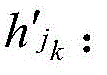
式(5)是中空间坐标(xi,yi,zi)是未知的,其余参数均已知。改写式(5)成式(6):Equation (5) is that the space coordinates (x i , y i , z i ) are unknown, and the rest of the parameters are known. Rewrite formula (5) into formula (6):
Gixi=gi (6)G i x i =g i (6)
式中xi=[xi,yi,zi]T,gi和Gi分别见式(7)和式(8):In the formula, x i =[x i , y i , z i ] T , and g i and G i are shown in formula (7) and formula (8) respectively:

最小二乘法求解式(6)得到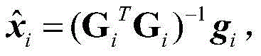


式中,β-和β⊥分别是1号成像系统水平和竖直方向上的当量像素,单位mm/pixel。In the formula, β - and β ⊥ are the equivalent pixels in the horizontal and vertical directions of the imaging system No. 1, respectively, in mm/pixel.
置信水平取95%,记1号成像系统的扩展不确定度为U95,dk的真值

式中,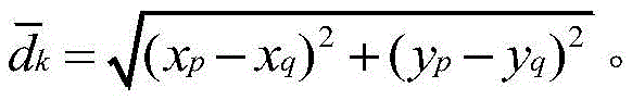
改变p和q的取值,重复以上过程,直到xi(i=1,2,…m)全部都建立起联系,所以在式(9)和式(10)中采用了下标k,其取值范围是[1,n],n应不小于m-1。Change the values of p and q and repeat the above process until all x i (i=1, 2,...m) are connected, so the subscript k is used in equations (9) and (10), which The value range is [1,n], and n should not be less than m-1.
将式(6)等价成式(11)所示的非线性无约束极值问题:Equation (6) is equivalent to the nonlinear unconstrained extreme value problem shown in Equation (11):

远心视觉系统的光学性能好,其测量精度远高于双目视觉系统。此外,双目视觉系统的测量精度可以达到1/10mm,在远心视觉系统的景深范围内。因此,基于以上两点将全部的式(10)作为约束条件,将式(11)变成非线性约束极值问题:The optical performance of the telecentric vision system is good, and its measurement accuracy is much higher than that of the binocular vision system. In addition, the measurement accuracy of the binocular vision system can reach 1/10mm, which is within the depth of field range of the telecentric vision system. Therefore, based on the above two points, all equations (10) are used as constraints, and equation (11) is transformed into a nonlinear constrained extreme value problem:
以最小二乘法的解作为初值,即


最后,利用上一步获得的三维坐标重建零件的三维模型,进行三维的多要素测量。Finally, the 3D model of the part is reconstructed using the 3D coordinates obtained in the previous step, and 3D multi-element measurement is performed.
以上所述仅为本发明的较佳实施例而已,并不用以限制本发明,凡在本发明的精神和原则之内所作的任何修改、等同替换和改进等,均应包含在本发明的保护范围之内。The above descriptions are only preferred embodiments of the present invention and are not intended to limit the present invention. Any modifications, equivalent replacements and improvements made within the spirit and principles of the present invention shall be included in the protection of the present invention. within the range.
Claims (5)


Priority Applications (1)
| Application Number | Priority Date | Filing Date | Title |
|---|---|---|---|
| CN201811194104.5A CN109579695B (en) | 2018-10-15 | 2018-10-15 | Part measuring method based on heterogeneous stereoscopic vision |
Applications Claiming Priority (1)
| Application Number | Priority Date | Filing Date | Title |
|---|---|---|---|
| CN201811194104.5A CN109579695B (en) | 2018-10-15 | 2018-10-15 | Part measuring method based on heterogeneous stereoscopic vision |
Publications (2)
| Publication Number | Publication Date |
|---|---|
| CN109579695A CN109579695A (en) | 2019-04-05 |
| CN109579695B true CN109579695B (en) | 2020-12-25 |
Family
ID=65920012
Family Applications (1)
| Application Number | Title | Priority Date | Filing Date |
|---|---|---|---|
| CN201811194104.5A Active CN109579695B (en) | 2018-10-15 | 2018-10-15 | Part measuring method based on heterogeneous stereoscopic vision |
Country Status (1)
| Country | Link |
|---|---|
| CN (1) | CN109579695B (en) |
Families Citing this family (8)
| Publication number | Priority date | Publication date | Assignee | Title |
|---|---|---|---|---|
| CN110470216B (en) * | 2019-07-10 | 2022-01-28 | 湖南交工智能技术有限公司 | Three-lens high-precision vision measurement method and device |
| CN111426268B (en) * | 2020-04-20 | 2021-09-24 | 武汉大学中南医院 | A Binocular Vision Camera Matching Method |
| CN111721197B (en) * | 2020-05-14 | 2022-02-01 | 南京工程学院 | Body model measuring device and method based on binocular stereo |
| CN111914857B (en) * | 2020-08-11 | 2023-05-09 | 上海柏楚电子科技股份有限公司 | Layout method, device and system for plate excess material, electronic equipment and storage medium |
| CN112237416A (en) * | 2020-09-10 | 2021-01-19 | 北京信息科技大学 | Fundus multi-mode imaging system calibration method based on retinal surface blood vessel characteristics |
| CN112489109B (en) * | 2020-11-19 | 2022-10-21 | 广州视源电子科技股份有限公司 | Three-dimensional imaging system method and device and three-dimensional imaging system |
| CN112991460B (en) * | 2021-03-10 | 2021-09-28 | 哈尔滨工业大学 | Binocular measurement system, method and device for obtaining size of automobile part |
| CN114535825B (en) * | 2022-04-28 | 2022-07-12 | 安普森智能科技(江苏)有限公司 | Laser marking vehicle identification code system based on manipulator |
Citations (3)
| Publication number | Priority date | Publication date | Assignee | Title |
|---|---|---|---|---|
| DE202010004039U1 (en) * | 2010-03-22 | 2010-06-17 | Modus High-Tech Electronics Gmbh | Device for optical quality control of three-dimensional objects |
| CN204479038U (en) * | 2015-02-27 | 2015-07-15 | 福建浩蓝光电有限公司 | Novel high resolving power vertical 3 D scanner |
| CN106483642A (en) * | 2016-12-14 | 2017-03-08 | 舜宇光学(中山)有限公司 | A kind of doubly telecentric camera lens based on machine vision |
Family Cites Families (1)
| Publication number | Priority date | Publication date | Assignee | Title |
|---|---|---|---|---|
| WO2018162979A1 (en) * | 2017-03-06 | 2018-09-13 | Spectrum Optix Inc. | Diamond shaped lens system |
-
2018
- 2018-10-15 CN CN201811194104.5A patent/CN109579695B/en active Active
Patent Citations (3)
| Publication number | Priority date | Publication date | Assignee | Title |
|---|---|---|---|---|
| DE202010004039U1 (en) * | 2010-03-22 | 2010-06-17 | Modus High-Tech Electronics Gmbh | Device for optical quality control of three-dimensional objects |
| CN204479038U (en) * | 2015-02-27 | 2015-07-15 | 福建浩蓝光电有限公司 | Novel high resolving power vertical 3 D scanner |
| CN106483642A (en) * | 2016-12-14 | 2017-03-08 | 舜宇光学(中山)有限公司 | A kind of doubly telecentric camera lens based on machine vision |
Also Published As
| Publication number | Publication date |
|---|---|
| CN109579695A (en) | 2019-04-05 |
Similar Documents
| Publication | Publication Date | Title |
|---|---|---|
| CN109579695B (en) | Part measuring method based on heterogeneous stereoscopic vision | |
| CN104075688B (en) | A kind of binocular solid stares the distance-finding method of monitoring system | |
| CN102867304B (en) | Method for establishing relation between scene stereoscopic depth and vision difference in binocular stereoscopic vision system | |
| Yang et al. | Robust and accurate surface measurement using structured light | |
| CN102032878B (en) | Accurate on-line measurement method based on binocular stereo vision measurement system | |
| CN109163657B (en) | Round target pose detection method based on binocular vision three-dimensional reconstruction | |
| CN103714571B (en) | A kind of based on photogrammetric single camera three-dimensional rebuilding method | |
| CN105547189B (en) | High-precision optical method for three-dimensional measurement based on mutative scale | |
| CN114998499A (en) | A method and system for binocular 3D reconstruction based on line laser galvanometer scanning | |
| CN104835158B (en) | 3D Point Cloud Acquisition Method Based on Gray Code Structured Light and Epipolar Constraint | |
| CN110728715A (en) | Camera angle self-adaptive adjusting method of intelligent inspection robot | |
| CN100388319C (en) | Multi-view pose estimation and self-calibration method for 3D active vision sensor | |
| CN104567728A (en) | Laser vision profile measurement system, measurement method and three-dimensional target | |
| CN106981083A (en) | The substep scaling method of Binocular Stereo Vision System camera parameters | |
| CN106500625B (en) | A kind of telecentricity stereo vision measurement method | |
| CN107358633A (en) | A Calibration Method of Internal and External Parameters of Multiple Cameras Based on Three-point Calibration Objects | |
| CN105043250B (en) | A kind of double-visual angle data alignment method based on 1 common indicium points | |
| CN104408762A (en) | Method for obtaining object image information and three-dimensional model by using monocular unit and two-dimensional platform | |
| Yang et al. | Geometric calibration of IR camera using trinocular vision | |
| CN109087339A (en) | A kind of laser scanning point and Image registration method | |
| CN1971206A (en) | Calibration method for binocular vision sensor based on one-dimension target | |
| CN103308000A (en) | Method for measuring curve object on basis of binocular vision | |
| CN104794718A (en) | Single-image CT (computed tomography) machine room camera calibration method | |
| CN116681827A (en) | A defect-free 3D point cloud reconstruction method and device based on multi-surveillance cameras and point cloud fusion | |
| CN105719290A (en) | Binocular stereo depth matching method adopting time domain visual sensor |
Legal Events
| Date | Code | Title | Description |
|---|---|---|---|
| PB01 | Publication | ||
| PB01 | Publication | ||
| SE01 | Entry into force of request for substantive examination | ||
| SE01 | Entry into force of request for substantive examination | ||
| GR01 | Patent grant | ||
| GR01 | Patent grant | ||
| EE01 | Entry into force of recordation of patent licensing contract |
Application publication date: 20190405 Assignee: Nanjing University of Engineering Science Park Co.,Ltd. Assignor: NANJING INSTITUTE OF TECHNOLOGY Contract record no.: X2024980001093 Denomination of invention: A Part Measurement Method Based on Heterogeneous Stereoscopic Vision Granted publication date: 20201225 License type: Common License Record date: 20240122 |
|
| EE01 | Entry into force of recordation of patent licensing contract | ||
| EE01 | Entry into force of recordation of patent licensing contract |
Application publication date: 20190405 Assignee: Nanjing Jinxi Yunchuang Technology Co.,Ltd. Assignor: NANJING INSTITUTE OF TECHNOLOGY Contract record no.: X2024980001805 Denomination of invention: A Part Measurement Method Based on Heterogeneous Stereoscopic Vision Granted publication date: 20201225 License type: Common License Record date: 20240202 |
|
| EE01 | Entry into force of recordation of patent licensing contract | ||
| EE01 | Entry into force of recordation of patent licensing contract |
Application publication date: 20190405 Assignee: Nanjing Institute of Engineering Technical Service Co.,Ltd. Assignor: NANJING INSTITUTE OF TECHNOLOGY Contract record no.: X2024980002478 Denomination of invention: A Part Measurement Method Based on Heterogeneous Stereoscopic Vision Granted publication date: 20201225 License type: Common License Record date: 20240305 |
|
| EE01 | Entry into force of recordation of patent licensing contract |