CN110728715A - Camera angle self-adaptive adjusting method of intelligent inspection robot - Google Patents
Camera angle self-adaptive adjusting method of intelligent inspection robot Download PDFInfo
- Publication number
- CN110728715A CN110728715A CN201910831148.2A CN201910831148A CN110728715A CN 110728715 A CN110728715 A CN 110728715A CN 201910831148 A CN201910831148 A CN 201910831148A CN 110728715 A CN110728715 A CN 110728715A
- Authority
- CN
- China
- Prior art keywords
- camera
- matrix
- image
- angle
- points
- Prior art date
- Legal status (The legal status is an assumption and is not a legal conclusion. Google has not performed a legal analysis and makes no representation as to the accuracy of the status listed.)
- Granted
Links
Images


Classifications
-
- G—PHYSICS
- G06—COMPUTING OR CALCULATING; COUNTING
- G06T—IMAGE DATA PROCESSING OR GENERATION, IN GENERAL
- G06T7/00—Image analysis
- G06T7/80—Analysis of captured images to determine intrinsic or extrinsic camera parameters, i.e. camera calibration
-
- G—PHYSICS
- G06—COMPUTING OR CALCULATING; COUNTING
- G06T—IMAGE DATA PROCESSING OR GENERATION, IN GENERAL
- G06T7/00—Image analysis
- G06T7/70—Determining position or orientation of objects or cameras
- G06T7/73—Determining position or orientation of objects or cameras using feature-based methods
- G06T7/74—Determining position or orientation of objects or cameras using feature-based methods involving reference images or patches
Landscapes
- Engineering & Computer Science (AREA)
- Computer Vision & Pattern Recognition (AREA)
- Physics & Mathematics (AREA)
- General Physics & Mathematics (AREA)
- Theoretical Computer Science (AREA)
- Length Measuring Devices By Optical Means (AREA)
Abstract
本发明公开了一种智能巡检机器人像机角度自适应调整方法,其步骤为:建立单目移动式视觉测量模型,获取像机的内参标定数据,根据机器人初始图像目标点位置,确定后续不同时刻机器人所获取的图像目标点,再结合求解出单应性矩阵,寻找目标点在初始图像中对应的图像匹配点,利用三角测量原理,实现不同时刻机器人获取的同一目标点在像机坐标系下的三维位姿信息,最后得到像机的偏转角度。本发明解决了智能巡检机器人在工作时目标偏离机器人像机视野中心的问题,在机器人定位误差和云台转动误差存在的情况下,可以自适应调整像机角度,实现目标的精准定位与准确识别,完成机器人目标的智能巡检、故障诊断、识别和预警。

The invention discloses an adaptive adjustment method for the camera angle of an intelligent inspection robot. The steps are as follows: establishing a monocular mobile vision measurement model, acquiring internal parameter calibration data of the camera, and determining the following different target points according to the position of the initial image target point of the robot. The image target points obtained by the robot at all times are combined with the homography matrix to find the corresponding image matching points of the target points in the initial image. Using the principle of triangulation, the same target point obtained by the robot at different times is realized in the camera coordinate system. The three-dimensional pose information below, and finally the deflection angle of the camera is obtained. The invention solves the problem that the target of the intelligent inspection robot deviates from the center of the vision of the robot camera when it is working. In the presence of the robot positioning error and the rotation error of the pan-tilt head, the camera angle can be adaptively adjusted to achieve precise positioning and accuracy of the target. Identify and complete intelligent inspection, fault diagnosis, identification and early warning of robot targets.
Description
技术领域technical field
本发明属于机器视觉测量技术领域,尤其涉及一种智能巡检机器人的像机角度自适应调整方法。The invention belongs to the technical field of machine vision measurement, and in particular relates to a camera angle adaptive adjustment method of an intelligent inspection robot.
背景技术Background technique
智能巡检机器人在特殊环境中替代人工巡检,不仅提高了现场巡检效率,降低了现场维护成本,而且减小了人工巡检的局限性,拓展了人工智能技术在特殊环境中的应用。智能巡检机器人在运行过程中,通过搭载云台和摄像机来获取要检测的设备信息和周围环境信息,利用图像处理和模式识别技术来实现特殊环境目标状态的分析和判断。在变电站、重要机房场合等特殊环境中,智能巡检机器人已经投入使用,对特殊环境中有关设备的智能检测、故障判断和周围环境异常预警取得了良好的效果。Intelligent inspection robots replace manual inspections in special environments, which not only improves the efficiency of on-site inspections, reduces on-site maintenance costs, but also reduces the limitations of manual inspections and expands the application of artificial intelligence technology in special environments. During the operation of the intelligent inspection robot, the equipment information to be detected and the surrounding environment information are obtained by carrying a pan/tilt and a camera, and image processing and pattern recognition technology are used to realize the analysis and judgment of the special environmental target state. In special environments such as substations and important computer rooms, intelligent inspection robots have been put into use, and have achieved good results in intelligent detection of relevant equipment in special environments, fault judgment and early warning of abnormal surrounding environments.
基于单目视觉的智能巡检机器人在巡检过程中,机器人在行走与驻停时存在一定的导航和定位误差,智能巡检机器人搭载的云台也存在一定的转动误差,导致机器人要巡检的目标偏离摄像机成像的视野中心,严重情况下造成目标完全偏离像机成像视野范围,无法对要检测的目标成像,给后续目标的智能检测和设备故障预警判断带来一定困难。During the inspection process of the intelligent inspection robot based on monocular vision, there are certain navigation and positioning errors when the robot walks and stops. The target deviates from the center of the imaging field of view of the camera. In severe cases, the target completely deviates from the imaging field of view of the camera, and the target to be detected cannot be imaged, which brings certain difficulties to the intelligent detection of the subsequent target and the early warning and judgment of equipment failure.
发明内容SUMMARY OF THE INVENTION
发明目的:针对现有技术中智能巡检机器人搭载的云台存在一定的转动误差的缺陷,本发明公开了一种智能巡检机器人的像机角度自适应调整方法,解决了智能巡检机器人在工作时目标偏离机器人像机视野中心位置的问题,帮助机器人对同一目标点在像机获取的图像的固定位置处成像,实现目标精准定位与准确识别。Purpose of the invention: Aiming at the defect that the pan/tilt carried by the intelligent inspection robot in the prior art has a certain rotation error, the present invention discloses an adaptive adjustment method of the camera angle of the intelligent inspection robot, which solves the problem of the intelligent inspection robot in the The problem that the target deviates from the center of the robot's camera field of view during work helps the robot to image the same target point at the fixed position of the image obtained by the camera, so as to achieve accurate target positioning and accurate identification.
技术方案:本发明公开了一种智能巡检机器人的像机角度自适应调整方法,其特征在于:包括以下步骤:Technical solution: The present invention discloses a camera angle adaptive adjustment method of an intelligent inspection robot, which is characterized by comprising the following steps:
步骤A、根据摄像机的针孔成像模型,利用平面方格点的摄像机标定方法,建立单目移动式测量系统模型;Step A. According to the pinhole imaging model of the camera, the camera calibration method of the plane grid point is utilized to establish a monocular mobile measurement system model;
步骤B、根据三维空间坐标点与平面二维坐标点的映射关系,求出像机的内参数矩阵;其中内参数矩阵指像机自身特性相关的参数,包括像机的焦距和像素大小;Step B, according to the mapping relationship between the three-dimensional space coordinate point and the plane two-dimensional coordinate point, obtain the internal parameter matrix of the camera; wherein the internal parameter matrix refers to the parameters related to the characteristics of the camera itself, including the focal length and pixel size of the camera;
步骤C、通过智能巡检机器人的像机,获得在同一位置处两个不同时刻的机器人拍摄的两幅图像,得出基础矩阵和本质矩阵的表达式;其中基础矩阵表示两视图对极几何的内在射影关系,本质矩阵表示归一化图像坐标下的基本矩阵;Step C. Obtain two images taken by the robot at two different times at the same position through the camera of the intelligent inspection robot, and obtain the expressions of the fundamental matrix and the essential matrix; wherein the fundamental matrix represents the epipolar geometry of the two views. The intrinsic projective relationship, the essential matrix represents the fundamental matrix in the normalized image coordinates;
步骤D、根据步骤C所得两幅图像的投影方程,提取两个图像特征点的位置信息,包括特征点的二维坐标值;Step D, according to the projection equations of the two images obtained in step C, extract the position information of the feature points of the two images, including the two-dimensional coordinate values of the feature points;
步骤E、结合步骤四提取的图像特征点,利用8点算法,求解出基础矩阵,再结合步骤B获得的内参数矩阵,求解出本质矩阵,对本质矩阵分解,可以求得摄像机外参矩阵;外参矩阵实现了把点从世界坐标系转换到摄像机坐标系的方法;其中摄像机外参矩阵包括旋转矩阵和平移矩阵;Step E, combine the image feature points extracted in step 4, and use the 8-point algorithm to solve the fundamental matrix, and then combine the internal parameter matrix obtained in step B to solve the essential matrix, and decompose the essential matrix to obtain the camera extrinsic parameter matrix; The external parameter matrix realizes the method of converting the point from the world coordinate system to the camera coordinate system; the camera external parameter matrix includes the rotation matrix and the translation matrix;
步骤F、根据两幅图像之间的至少4对匹配特征点,结合SVD算法,求解两幅图像之间的单应性矩阵;其中单应性矩阵是指一个图像平面到另外一个图像平面的投影映射;Step F. According to at least 4 pairs of matching feature points between the two images, combined with the SVD algorithm, solve the homography matrix between the two images; wherein the homography matrix refers to the projection of one image plane to another image plane map;
步骤G、利用机器人前后两个时刻获取的两幅图像的特征点对应的图像位置,根据步骤F求出的单应性矩阵,结合双目立体视觉测量原理和步骤E求出的像机内参数和外部结构参数,求出像机需要转动的角度,其中像机转动的角度就是机器人云台转动的角度;这个角度是在像机坐标系下的角度,可以按照像机坐标系的x和y轴进行分解,即是像机的左右和上下的转动角度,一般通过分解之后,传递给像机的云台,即可实现像机角度的调整。Step G, using the image positions corresponding to the feature points of the two images obtained at the two moments before and after the robot, according to the homography matrix obtained in step F, combined with the binocular stereo vision measurement principle and the in-camera parameters obtained in step E and the external structural parameters to find the angle that the camera needs to rotate, in which the angle of the camera rotation is the rotation angle of the robot gimbal; this angle is the angle in the camera coordinate system, which can be determined according to the x and y of the camera coordinate system. The axis is decomposed, that is, the left and right and up and down rotation angles of the camera. Generally, the camera angle can be adjusted after being decomposed and transmitted to the camera's PTZ.
优选地,所述步骤D还包括:Preferably, the step D further comprises:
D1:在图像的重叠区域对SIFT特征点进行提取和匹配;D1: Extract and match SIFT feature points in the overlapping area of the image;
D2:利用RANSAC算法剔除图像对中的误匹配点,实现两幅图像间的SIFT特征点的精确配准。D2: Use the RANSAC algorithm to eliminate the mismatched points in the image pair to achieve accurate registration of the SIFT feature points between the two images.
优选地,所述步骤F还包括:Preferably, the step F further comprises:
F1:根据像机的透视投影模型两个时刻的图像之间的匹配点的图像坐标系和世界坐标系之间的关系式;F1: The relational expression between the image coordinate system and the world coordinate system of the matching point between the images of the two moments according to the perspective projection model of the camera;
F2:根据至少4对匹配特征点,利用SVD(奇异值分解法)求解两幅图像之间的单应性矩阵。F2: According to at least 4 pairs of matching feature points, use SVD (singular value decomposition) to solve the homography matrix between two images.
优选地,所述步骤C中基础矩阵和本质矩阵的表达式为:Preferably, the expressions of the fundamental matrix and the essential matrix in the step C are:

E=SRE=SR
其中F为基础矩阵,E为本质矩阵,R为旋转矩阵,S为反对称矩阵,Ar和Al为两不同时刻像机内参数矩阵。Among them, F is the fundamental matrix, E is the essential matrix, R is the rotation matrix, S is the antisymmetric matrix, and A r and A l are the internal parameter matrices of the camera at two different times.
优选地,所述步骤G中像机转动的角度表达式为:Preferably, the expression of the angle of rotation of the camera in the step G is:
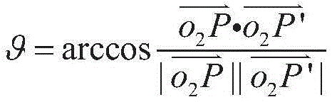
其中,P为步骤D中两幅图像匹配特征点中的一组匹配特征点对中其中一个特征点对应的空间特征点,P′为根据步骤G计算得出的虚拟空间三维点,所求出的像机坐标系下的角度,根据像机坐标系的x和y轴进行分解,分别代表像机的左右和上下的转动角度,分解之后传递给像机的云台,实现像机角度的调整。Among them, P is the spatial feature point corresponding to one of the matching feature points in a set of matching feature points of the two images in step D, and P' is the virtual space three-dimensional point calculated according to step G. The angle in the camera coordinate system is decomposed according to the x and y axes of the camera coordinate system, representing the left and right and up and down rotation angles of the camera respectively. .
有益效果:本发明公开了一种智能巡检机器人的像机角度自适应调整方法,结合单目视觉技术,利用机器人在同一位置不同时刻拍摄的两幅图像,实现两幅图像特征的提取和匹配,利用移动式单目视觉定位技术,完成目标点的三维重建。通过求解出的两组对应点的图像坐标和世界坐标系下的三维坐标,实现在多种定位误差存在的情况下机器人搭载的摄像机角度的自适应调整。本发明解决了智能巡检机器人在工作时目标偏离机器人像机视野中心位置的问题,在机器人定位误差和云台转动误差存在的情况下,可以自适应调整像机角度,实现目标精准定位与准确识别,完成了对机器人目标的智能巡检、故障诊断、识别和预警。Beneficial effects: The invention discloses a camera angle adaptive adjustment method of an intelligent inspection robot, which combines the monocular vision technology and utilizes two images taken by the robot at the same position at different times to realize the extraction and matching of the features of the two images. , using the mobile monocular vision positioning technology to complete the three-dimensional reconstruction of the target point. Through the obtained image coordinates of the two sets of corresponding points and the three-dimensional coordinates in the world coordinate system, the self-adaptive adjustment of the camera angle carried by the robot in the presence of various positioning errors is realized. The invention solves the problem that the target of the intelligent inspection robot deviates from the center position of the robot's camera field of view during operation. In the presence of robot positioning error and pan-tilt rotation error, the camera angle can be adaptively adjusted to achieve precise positioning and accuracy of the target. It has completed the intelligent inspection, fault diagnosis, identification and early warning of the robot target.
附图说明Description of drawings
图1为本发明的流程图;Fig. 1 is the flow chart of the present invention;
图2为本发明的单目移动式智能巡检机器人结构图;Fig. 2 is the monocular mobile intelligent inspection robot structure diagram of the present invention;
其中1为智能巡检机器人搭载的摄像机,2为可以左右和上下移动的具有四自由度的云台,3为激光雷达,4为探沟传感器,5为四驱底盘,6为防撞开关;Among them, 1 is a camera mounted on the intelligent inspection robot, 2 is a pan/tilt with four degrees of freedom that can move left and right and up and down, 3 is a lidar, 4 is a trench sensor, 5 is a four-wheel drive chassis, and 6 is an anti-collision switch;
图3为本发明的特征的提取与匹配图;Fig. 3 is the extraction and matching diagram of the feature of the present invention;
图4为本发明的单目移动式机器人组成的双目视觉测量系统和求取像机角度偏转示意图。FIG. 4 is a schematic diagram of a binocular vision measurement system composed of a monocular mobile robot according to the present invention and an angle deflection of a camera.
具体实施方式Detailed ways
本发明公开了一种智能巡检机器人的像机角度自适应调整方法,其特征在于:包括以下步骤:The invention discloses a camera angle adaptive adjustment method of an intelligent inspection robot, which is characterized by comprising the following steps:
步骤A、根据摄像机的针孔成像模型,利用平面方格点的摄像机标定方法,建立单目移动式测量系统模型;移动式单目视觉测量系统是通过一个像机经过移动,虚拟成多个像机,形成多目视觉测量系统。本发明以在某一位置处两个不同时刻的机器人拍摄的两幅图像构成两视图视觉测量为例,分析移动式单目视觉组成的双目立体视觉测量系统原理。Step A. According to the pinhole imaging model of the camera, the camera calibration method of plane grid points is used to establish a monocular mobile measurement system model; the mobile monocular vision measurement system is moved by a camera to virtually form multiple images machine to form a multi-eye vision measurement system. The present invention analyzes the principle of a binocular stereo vision measurement system composed of a mobile monocular vision by taking two images taken by a robot at a certain position at two different times to form a two-view vision measurement as an example.
步骤B、根据三维空间坐标点与平面二维坐标点的映射关系求出像机的内参数矩阵;假定靶标平面的三维点的齐次坐标记为


其中,s为一任意的非零尺度因子,[R t]是一个3行4列的矩阵,称为像机外参数矩阵,R称为旋转矩阵,t=(t1,t2,t3)T,称为平移矩阵,
步骤C、通过智能巡检机器人的像机,获得在某一位置处两个不同时刻的机器人拍摄的两幅图像,得出基础矩阵和本质矩阵的表达式;假设空间一点P的世界三维齐次坐标为Xw,分别在两个时刻拍摄的两幅图像中二维图像齐次坐标为p1和p2,则由式(1)可以得到两个时刻摄像机的投影方程为Step C. Through the camera of the intelligent inspection robot, two images taken by the robot at two different times at a certain position are obtained, and the expressions of the fundamental matrix and the essential matrix are obtained; it is assumed that the world at a point P in space is three-dimensionally homogeneous The coordinates are X w , and the homogeneous coordinates of the two-dimensional images in the two images captured at two moments are p 1 and p 2 , then the projection equations of the cameras at the two moments can be obtained from equation (1) as follows:

其中,s1和s2是两个像机的非零尺度因子,A1和A2分别是像机在时刻1和时刻2的像机内参,因为像机只有刚性移动,内部结构参数没有变化,所以A1=A2。Among them, s 1 and s 2 are the non-zero scale factors of the two cameras, A 1 and A 2 are the camera internal parameters of the camera at time 1 and
优选地,所述步骤C中结合极线几何约束关系,由(2)式可以求出基本矩阵F和本质矩阵E的表达式,分别如下:Preferably, in the step C, combined with the epipolar geometric constraint relationship, the expressions of the fundamental matrix F and the essential matrix E can be obtained from the formula (2), which are respectively as follows:

E=SR (4)E=SR (4)
其中,S为反对称矩阵,
从(3)式可以看出,基础矩阵F只与两个摄像机的内部参数和系统的外部结构参数有关,而搭载摄像机由于通过云台转动,只做刚体运动,像机内部参数不变。因此,可以得到(4)式的本质矩阵E,可以看出E只与视觉系统的外部参数有关,E可以分解求出移动式单目视觉测量系统的两视图模型之间的外部结构参数R和t。It can be seen from formula (3) that the fundamental matrix F is only related to the internal parameters of the two cameras and the external structural parameters of the system, while the mounted camera only performs rigid body motion due to the rotation of the PTZ, and the internal parameters of the camera remain unchanged. Therefore, the essential matrix E of formula (4) can be obtained. It can be seen that E is only related to the external parameters of the vision system. E can be decomposed to obtain the external structural parameters R and R between the two view models of the mobile monocular vision measurement system. t.
步骤D、根据步骤C所得两幅图像的投影方程,提取两个图像特征点;Step D, according to the projection equation of the two images obtained in step C, extract two image feature points;
优选地,所述步骤D还包括:Preferably, the step D further comprises:
D1:在图像的重叠区域对SIFT特征点进行提取和匹配;D1: Extract and match SIFT feature points in the overlapping area of the image;
D2:利用RANSAC算法剔除图像对中的误匹配点,实现两幅图像间的SIFT特征点的精确配准。D2: Use the RANSAC algorithm to eliminate the mismatched points in the image pair to achieve accurate registration of the SIFT feature points between the two images.
本发明利用SIFT特征点(尺度不变特征变换)的特性,即SIFT特征对图像旋转、尺度缩放以及亮度变化等保持不变,对两不同时刻在某一位置处由机器人像机捕获的具有重叠区域的图像对进行SIFT特征提取,并利用RANSAC算法剔除图像对中的误匹配点,实现两幅图像间的SIFT特征点的精确配准。如图3所示,在某一位置处,由于巡检机器人存在导航定位误差和云台角度转动误差,搭载的像机在不同时刻对同一目标成像,会获得具有重叠区域的两幅图像,在图像的重叠区域对SIFT特征点进行提取和匹配。结合公式(3)和(4),利用上述分析的8点算法,可以求出两视图像机坐标系下之间的外部结构参数R和t,外部参数对空间三维点的重建具有重要作用。The present invention utilizes the characteristics of SIFT feature points (scale-invariant feature transformation), that is, the SIFT features remain unchanged for image rotation, scale scaling, and brightness changes, and overlap with those captured by a robot camera at a certain position at two different times. The SIFT feature extraction is performed on the image pairs in the region, and the RANSAC algorithm is used to eliminate the mismatched points in the image pairs to achieve accurate registration of the SIFT feature points between the two images. As shown in Figure 3, at a certain position, due to the navigation positioning error and the pan-tilt angle rotation error of the inspection robot, the mounted camera images the same target at different times, and two images with overlapping areas will be obtained. The SIFT feature points are extracted and matched in the overlapping area of the image. Combining formulas (3) and (4), using the 8-point algorithm analyzed above, the external structural parameters R and t between the two-view camera coordinate systems can be obtained. The external parameters play an important role in the reconstruction of three-dimensional points in space.
步骤E、结合步骤四提取的图像特征点,利用8点算法,求解出基础矩阵,再结合步骤B获得的内参数矩阵,求解出本质矩阵,对本质矩阵分解,可以求得两个图像之间的外部结构参数矩阵;从极线几何约束关系以及本质矩阵的定义可以看出,基础矩阵为具有7个自由度、秩为2的矩阵,通过两幅图像特征点的提取和匹配,利用8点算法,可以求出两视图图像之间的基础矩阵F,结合像机的内部参数,可以求出本质矩阵E。通过对本质矩阵E的分解,可以最终求得两视图之间的外部结构参数R和t。Step E, combine the image feature points extracted in step 4, use the 8-point algorithm to solve the fundamental matrix, and then combine with the internal parameter matrix obtained in step B to solve the essential matrix, and decompose the essential matrix to obtain the difference between the two images. The external structure parameter matrix of algorithm, the fundamental matrix F between the two view images can be obtained, and the essential matrix E can be obtained by combining with the internal parameters of the camera. By decomposing the essential matrix E, the external structural parameters R and t between the two views can be finally obtained.
步骤F、根据两幅图像间至少4对匹配点,利用SVD(奇异值分解法),可以求解两幅图像之间的单应性矩阵;Step F, according to at least 4 pairs of matching points between two images, utilize SVD (singular value decomposition method), can solve the homography matrix between two images;
优选地,所述步骤F还包括:Preferably, the step F further comprises:
F1:根据像机的透视投影模型两个时刻的图像之间的匹配点的图像坐标系和世界坐标系之间的关系式;F1: The relational expression between the image coordinate system and the world coordinate system of the matching point between the images of the two moments according to the perspective projection model of the camera;
F2:根据SVD分解法求解单应性矩阵。F2: Solve the homography matrix according to the SVD decomposition method.
结合两幅图像匹配特征点的信息,利用像机的透视投影模型,可以分别得到两个时刻的图像之间的匹配点的图像坐标系和世界坐标系之间的关系式,Combining the information of the matching feature points of the two images, using the perspective projection model of the camera, the relationship between the image coordinate system and the world coordinate system of the matching point between the images at the two moments can be obtained respectively,


由公式(5)和(6)可得,It can be obtained from formulas (5) and (6),

令
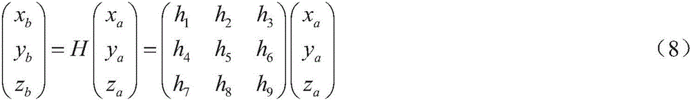
由公式(8)可以得到From formula (8), we can get

其中,(ua,va)和(ub,vb)为两幅图像上的匹配点对。where (u a , v a ) and (u b , v b ) are matched point pairs on the two images.
由公式(9)可知,每一对特征点可以得到两个方程,H矩阵为秩为8的奇异矩阵,则至少4对匹配点即可解出两幅平面的单应性矩阵H。求解单应性矩阵H的一个常用方法为SVD分解法。It can be seen from formula (9) that two equations can be obtained for each pair of feature points. The H matrix is a singular matrix of rank 8, and at least 4 pairs of matching points can solve the homography matrix H of the two planes. A common method for solving the homography matrix H is the SVD decomposition method.
步骤G、根据步骤F求出的单应性矩阵,求出两幅图像特征点对应的虚拟空间三维点,结合双目立体视觉测量原理和系统外部结构参数矩阵,求出像机转动的角度;这个角度是在像机坐标系下的角度,可以按照像机坐标系的x和y轴进行分解,即是像机的左右和上下的转动角度,一般通过分解之后,传递给像机的云台,即可实现像机角度的调整。Step G, obtain the homography matrix obtained according to step F, obtain the virtual space three-dimensional point corresponding to the feature points of the two images, combine the binocular stereo vision measurement principle and the external structure parameter matrix of the system, obtain the angle of the camera rotation; This angle is the angle in the camera coordinate system, which can be decomposed according to the x and y axes of the camera coordinate system, that is, the left and right and up and down rotation angles of the camera. , the camera angle can be adjusted.
优选地,所述步骤G中像机转动的角度表达式为:Preferably, the expression of the angle of rotation of the camera in the step G is:

其中,P为步骤D中两幅图像匹配特征点中的一组匹配特征点对中其中一个特征点对应的空间特征点,P′为根据步骤G计算得出的虚拟空间三维点,所求出的像机坐标系下的角度,根据像机坐标系的x和y轴进行分解,分别代表像机的左右和上下的转动角度,分解之后传递给像机的云台,实现像机角度的调整。Among them, P is the spatial feature point corresponding to one of the matching feature points in a set of matching feature points of the two images in step D, and P' is the virtual space three-dimensional point calculated according to step G. The angle in the camera coordinate system is decomposed according to the x and y axes of the camera coordinate system, representing the left and right and up and down rotation angles of the camera respectively. .
在求解出两幅图像的单应性矩阵H与两视图像机坐标系外部结构参数R和t之后,以第一幅图像作为基准图像,选取两幅图像中匹配特征点中的一组匹配特征点对p和q,对应的空间特征点为P,其在对应两幅图像中的图像坐标分别为p=(xa,ya)和q=(xb,yb),如图4所示。结合双目立体视觉测量原理,对经过精确标定后的两视图像机测量系统,已知两点的图像坐标和外部结构参数R和t,可以精确求取空间点P的三维世界坐标系,此时把世界坐标系建立在像机2坐标系下,从而计算像机旋转的角度。假设此时计算出的空间点P的世界三维坐标为P=(X1,Y1,Z1)。After solving the homography matrix H of the two images and the external structure parameters R and t of the two-view camera coordinate system, the first image is used as the reference image, and a set of matching features in the matching feature points in the two images is selected. For the point pair p and q, the corresponding spatial feature point is P, and its image coordinates in the corresponding two images are respectively p=(x a , y a ) and q=(x b , y b ), as shown in Figure 4 Show. Combined with the principle of binocular stereo vision measurement, for the accurately calibrated dual-view image machine measurement system, the image coordinates of the two points and the external structural parameters R and t are known, and the three-dimensional world coordinate system of the space point P can be accurately obtained. When the world coordinate system is established in the
由于机器人存在导航和定位误差,不同时刻拍摄的两幅图像的匹配特征点图像坐标存在偏差,如图4所示的匹配特征点对p和q,一个在主点右侧,一个在主点左侧。假设机器人导航和定位精准,不存在上述误差,在图像1中设图像坐标为p=(xa,ya),那么时刻1像机所在位置和角度应与时刻2像机位置和角度相同,所以在第2幅图像中,与其在图像1中的p点对应的匹配点的图像坐标应为q′=(xa,ya)。而实际上由于误差的存在,导致在时刻2像机位置和角度偏离在时刻1的像机位置和角度。Due to the navigation and positioning errors of the robot, there is a deviation in the image coordinates of the matching feature points of the two images taken at different times. side. Assuming that the robot's navigation and positioning are accurate and the above errors do not exist, and the image coordinates in image 1 are set as p=(x a , y a ), then the position and angle of the camera at time 1 should be the same as the position and angle of the camera at
本发明是在导航误差存在的情况下,不改变巡检机器人的位置,通过转动云台角度,调整像机的拍摄位置,达到目标不偏离图像中心位置。云台转动角度,通过像机计算的角度误差来求出。The present invention does not change the position of the inspection robot under the condition of the existence of navigation error, and adjusts the shooting position of the camera by rotating the angle of the pan/tilt, so that the target does not deviate from the center position of the image. The rotation angle of the gimbal is calculated by the angle error calculated by the camera.
由上述分析可知,目标点如果要想达到在时刻2拍摄的图像上的位置与在时刻1拍摄的图像上具有相同的图像坐标,在保持机器人不移动的情况下,位置2时刻的像机应该移动角度为∠qo2q′。It can be seen from the above analysis that if the target point wants to achieve the position on the image captured at
实际上,由上述求出两幅图像的单应性矩阵H,可以求出与在图像2中的点q′=(xa,ya)对应的在图像1中的匹配点p′,如图4所示,即In fact, by obtaining the homography matrix H of the two images above, the matching point p' in image 1 corresponding to the point q'=(x a , ya ) in
p′=H-Tq′=H-T(xa,ya,1) (10)p'=H -T q'=H -T (x a , ya , 1) (10)
其中p′与q′为虚拟图像匹配点对,二者对应的空间点为P′,即为虚拟空间三维点。同理,已知对应点对p′与q′图像坐标,和系统外部结构参数R和t,结合双目立体视觉测量原理,可以求出虚拟空间点P′的三维世界坐标,假设计算出的P′=(X′1,Y′1,Z′1)。由图4分析,因为空间点的三维坐标建立在像机2坐标系下,∠qo2q′=∠Po2P′,像机2移动的角度应该由下式来计算,即Among them, p' and q' are virtual image matching point pairs, and the space point corresponding to them is P', which is a three-dimensional point in virtual space. In the same way, the image coordinates of the corresponding point pair p' and q', and the external structural parameters R and t of the system are known, combined with the principle of binocular stereo vision measurement, the three-dimensional world coordinates of the virtual space point P' can be obtained. Assuming that the calculated P'=(X' 1 , Y' 1 , Z' 1 ). From the analysis in Figure 4, because the three-dimensional coordinates of the space point are established in the coordinate system of the
通过对(11)式进行分解,即可以求出像机应该旋转的角度,也即是机器人云台应该转动的角度。By decomposing (11), the angle that the camera should rotate, that is, the angle that the robot head should rotate.
以上所述仅是本发明的优选实施方式,应当指出:对于本技术领域的普通技术人员来说,在不脱离本发明原理的前提下,还可以做出若干改进和润饰,这些改进和润饰也应视为本发明的保护范围。The above is only the preferred embodiment of the present invention, it should be pointed out that: for those skilled in the art, without departing from the principle of the present invention, several improvements and modifications can also be made, and these improvements and modifications are also It should be regarded as the protection scope of the present invention.
Claims (7)


Priority Applications (1)
| Application Number | Priority Date | Filing Date | Title |
|---|---|---|---|
| CN201910831148.2A CN110728715B (en) | 2019-09-06 | 2019-09-06 | A method for self-adaptive adjustment of the camera angle of an intelligent inspection robot |
Applications Claiming Priority (1)
| Application Number | Priority Date | Filing Date | Title |
|---|---|---|---|
| CN201910831148.2A CN110728715B (en) | 2019-09-06 | 2019-09-06 | A method for self-adaptive adjustment of the camera angle of an intelligent inspection robot |
Publications (2)
| Publication Number | Publication Date |
|---|---|
| CN110728715A true CN110728715A (en) | 2020-01-24 |
| CN110728715B CN110728715B (en) | 2023-04-25 |
Family
ID=69218886
Family Applications (1)
| Application Number | Title | Priority Date | Filing Date |
|---|---|---|---|
| CN201910831148.2A Active CN110728715B (en) | 2019-09-06 | 2019-09-06 | A method for self-adaptive adjustment of the camera angle of an intelligent inspection robot |
Country Status (1)
| Country | Link |
|---|---|
| CN (1) | CN110728715B (en) |
Cited By (24)
| Publication number | Priority date | Publication date | Assignee | Title |
|---|---|---|---|---|
| CN111311681A (en) * | 2020-02-14 | 2020-06-19 | 北京云迹科技有限公司 | Visual positioning method, device, robot and computer readable storage medium |
| CN111409085A (en) * | 2020-04-27 | 2020-07-14 | 浙江库科自动化科技有限公司 | Inspection intelligent robot with folding angle cock closing function and inspection method thereof |
| CN111611913A (en) * | 2020-05-20 | 2020-09-01 | 北京海月水母科技有限公司 | Human-shaped positioning technology of monocular face recognition probe |
| CN111914715A (en) * | 2020-07-24 | 2020-11-10 | 廊坊和易生活网络科技股份有限公司 | Intelligent vehicle target real-time detection and positioning method based on bionic vision |
| CN111932623A (en) * | 2020-08-11 | 2020-11-13 | 北京洛必德科技有限公司 | Face data automatic acquisition and labeling method and system based on mobile robot and electronic equipment thereof |
| CN112184834A (en) * | 2020-10-07 | 2021-01-05 | 浙江港创智能机器人有限公司 | Autonomous inspection method for overhead transmission line |
| CN112598743A (en) * | 2021-02-08 | 2021-04-02 | 智道网联科技(北京)有限公司 | Pose estimation method of monocular visual image and related device |
| CN112634433A (en) * | 2020-12-07 | 2021-04-09 | 北京达美盛软件股份有限公司 | Real-time control and visualization system of digital factory |
| CN112714287A (en) * | 2020-12-23 | 2021-04-27 | 广东科凯达智能机器人有限公司 | Pan-tilt target conversion control method, device, equipment and storage medium |
| CN112949478A (en) * | 2021-03-01 | 2021-06-11 | 浙江国自机器人技术股份有限公司 | Target detection method based on holder camera |
| WO2021208486A1 (en) * | 2020-04-16 | 2021-10-21 | 深圳先进技术研究院 | Camera coordinate transformation method, terminal, and storage medium |
| CN113758499A (en) * | 2021-03-18 | 2021-12-07 | 北京京东乾石科技有限公司 | Method, device and equipment for determining assembly deviation compensation parameters of positioning sensor |
| CN114170306A (en) * | 2021-11-17 | 2022-03-11 | 埃洛克航空科技(北京)有限公司 | Image attitude estimation method, device, terminal and storage medium |
| CN114549282A (en) * | 2022-01-11 | 2022-05-27 | 深圳昱拓智能有限公司 | Method and system for realizing multi-meter reading based on affine transformation |
| WO2022121911A1 (en) * | 2020-12-07 | 2022-06-16 | 北京达美盛软件股份有限公司 | Virtual inspection system and visualized factory system in augmented reality environment |
| CN114862969A (en) * | 2022-05-27 | 2022-08-05 | 国网江苏省电力有限公司电力科学研究院 | Onboard holder camera angle self-adaptive adjusting method and device of intelligent inspection robot |
| CN115222822A (en) * | 2022-07-21 | 2022-10-21 | 武汉拓行智网科技有限公司 | Mobile camera positioning correction method and device based on long-distance shooting |
| CN115393407A (en) * | 2022-08-29 | 2022-11-25 | 杜霖 | Image external reference calibration method and device, equipment and storage medium |
| CN115958609A (en) * | 2023-03-16 | 2023-04-14 | 山东卓朗检测股份有限公司 | Instruction data safety early warning method based on intelligent robot automatic control system |
| CN116447979A (en) * | 2023-03-13 | 2023-07-18 | 招商局重庆公路工程检测中心有限公司 | Binocular vision slope displacement monitoring method and device based on unmanned aerial vehicle |
| CN116563336A (en) * | 2023-04-03 | 2023-08-08 | 国网江苏省电力有限公司南通供电分公司 | Adaptive positioning algorithm for target tracking in digital twin computer room |
| CN116896608A (en) * | 2023-09-11 | 2023-10-17 | 山东省地震局 | A virtual earthquake scene broadcast system based on mobile device communication |
| CN117058197A (en) * | 2023-07-26 | 2023-11-14 | 中国科学院自动化研究所 | Spatial registration method and device for neuromodulation |
| CN119582380A (en) * | 2024-02-28 | 2025-03-07 | 江苏财经职业技术学院 | An adaptive charging control method and system for inspection robots |
Citations (6)
| Publication number | Priority date | Publication date | Assignee | Title |
|---|---|---|---|---|
| WO2011143813A1 (en) * | 2010-05-19 | 2011-11-24 | 深圳泰山在线科技有限公司 | Object projection method and object projection sysytem |
| CN104376552A (en) * | 2014-09-19 | 2015-02-25 | 四川大学 | Virtual-real registering algorithm of 3D model and two-dimensional image |
| CN104596502A (en) * | 2015-01-23 | 2015-05-06 | 浙江大学 | Object posture measuring method based on CAD model and monocular vision |
| CN106679648A (en) * | 2016-12-08 | 2017-05-17 | 东南大学 | Vision-inertia integrated SLAM (Simultaneous Localization and Mapping) method based on genetic algorithm |
| WO2018124337A1 (en) * | 2016-12-28 | 2018-07-05 | 주식회사 에이다스원 | Object detection method and apparatus utilizing adaptive area of interest and discovery window |
| CN109102525A (en) * | 2018-07-19 | 2018-12-28 | 浙江工业大学 | A kind of mobile robot follow-up control method based on the estimation of adaptive pose |
-
2019
- 2019-09-06 CN CN201910831148.2A patent/CN110728715B/en active Active
Patent Citations (6)
| Publication number | Priority date | Publication date | Assignee | Title |
|---|---|---|---|---|
| WO2011143813A1 (en) * | 2010-05-19 | 2011-11-24 | 深圳泰山在线科技有限公司 | Object projection method and object projection sysytem |
| CN104376552A (en) * | 2014-09-19 | 2015-02-25 | 四川大学 | Virtual-real registering algorithm of 3D model and two-dimensional image |
| CN104596502A (en) * | 2015-01-23 | 2015-05-06 | 浙江大学 | Object posture measuring method based on CAD model and monocular vision |
| CN106679648A (en) * | 2016-12-08 | 2017-05-17 | 东南大学 | Vision-inertia integrated SLAM (Simultaneous Localization and Mapping) method based on genetic algorithm |
| WO2018124337A1 (en) * | 2016-12-28 | 2018-07-05 | 주식회사 에이다스원 | Object detection method and apparatus utilizing adaptive area of interest and discovery window |
| CN109102525A (en) * | 2018-07-19 | 2018-12-28 | 浙江工业大学 | A kind of mobile robot follow-up control method based on the estimation of adaptive pose |
Non-Patent Citations (1)
| Title |
|---|
| 洪磊等: "ABB1410工业机器人的旋量运动学逆解方法", 《机械设计与制造》 * |
Cited By (32)
| Publication number | Priority date | Publication date | Assignee | Title |
|---|---|---|---|---|
| CN111311681A (en) * | 2020-02-14 | 2020-06-19 | 北京云迹科技有限公司 | Visual positioning method, device, robot and computer readable storage medium |
| WO2021208486A1 (en) * | 2020-04-16 | 2021-10-21 | 深圳先进技术研究院 | Camera coordinate transformation method, terminal, and storage medium |
| CN111409085A (en) * | 2020-04-27 | 2020-07-14 | 浙江库科自动化科技有限公司 | Inspection intelligent robot with folding angle cock closing function and inspection method thereof |
| CN111611913A (en) * | 2020-05-20 | 2020-09-01 | 北京海月水母科技有限公司 | Human-shaped positioning technology of monocular face recognition probe |
| CN111914715B (en) * | 2020-07-24 | 2021-07-16 | 廊坊和易生活网络科技股份有限公司 | Intelligent vehicle target real-time detection and positioning method based on bionic vision |
| CN111914715A (en) * | 2020-07-24 | 2020-11-10 | 廊坊和易生活网络科技股份有限公司 | Intelligent vehicle target real-time detection and positioning method based on bionic vision |
| CN111932623A (en) * | 2020-08-11 | 2020-11-13 | 北京洛必德科技有限公司 | Face data automatic acquisition and labeling method and system based on mobile robot and electronic equipment thereof |
| CN112184834A (en) * | 2020-10-07 | 2021-01-05 | 浙江港创智能机器人有限公司 | Autonomous inspection method for overhead transmission line |
| CN112634433A (en) * | 2020-12-07 | 2021-04-09 | 北京达美盛软件股份有限公司 | Real-time control and visualization system of digital factory |
| WO2022121911A1 (en) * | 2020-12-07 | 2022-06-16 | 北京达美盛软件股份有限公司 | Virtual inspection system and visualized factory system in augmented reality environment |
| WO2022134490A1 (en) * | 2020-12-23 | 2022-06-30 | 广东科凯达智能机器人有限公司 | Gimbal target conversion control method, apparatus, device, and storage medium |
| CN112714287A (en) * | 2020-12-23 | 2021-04-27 | 广东科凯达智能机器人有限公司 | Pan-tilt target conversion control method, device, equipment and storage medium |
| CN112598743A (en) * | 2021-02-08 | 2021-04-02 | 智道网联科技(北京)有限公司 | Pose estimation method of monocular visual image and related device |
| CN112598743B (en) * | 2021-02-08 | 2023-10-13 | 智道网联科技(北京)有限公司 | Pose estimation method and related device for monocular vision image |
| CN112949478A (en) * | 2021-03-01 | 2021-06-11 | 浙江国自机器人技术股份有限公司 | Target detection method based on holder camera |
| CN113758499A (en) * | 2021-03-18 | 2021-12-07 | 北京京东乾石科技有限公司 | Method, device and equipment for determining assembly deviation compensation parameters of positioning sensor |
| CN113758499B (en) * | 2021-03-18 | 2024-05-17 | 北京京东乾石科技有限公司 | Method, device and apparatus for determining positioning sensor assembly deviation compensation parameters |
| CN114170306A (en) * | 2021-11-17 | 2022-03-11 | 埃洛克航空科技(北京)有限公司 | Image attitude estimation method, device, terminal and storage medium |
| CN114549282A (en) * | 2022-01-11 | 2022-05-27 | 深圳昱拓智能有限公司 | Method and system for realizing multi-meter reading based on affine transformation |
| CN114549282B (en) * | 2022-01-11 | 2023-12-12 | 深圳昱拓智能有限公司 | Method and system for realizing multi-meter reading based on affine transformation |
| CN114862969A (en) * | 2022-05-27 | 2022-08-05 | 国网江苏省电力有限公司电力科学研究院 | Onboard holder camera angle self-adaptive adjusting method and device of intelligent inspection robot |
| CN115222822A (en) * | 2022-07-21 | 2022-10-21 | 武汉拓行智网科技有限公司 | Mobile camera positioning correction method and device based on long-distance shooting |
| CN115393407B (en) * | 2022-08-29 | 2025-07-29 | 杜霖 | External reference calibration method and device for image, equipment and storage medium |
| CN115393407A (en) * | 2022-08-29 | 2022-11-25 | 杜霖 | Image external reference calibration method and device, equipment and storage medium |
| CN116447979A (en) * | 2023-03-13 | 2023-07-18 | 招商局重庆公路工程检测中心有限公司 | Binocular vision slope displacement monitoring method and device based on unmanned aerial vehicle |
| CN115958609B (en) * | 2023-03-16 | 2023-07-14 | 山东卓朗检测股份有限公司 | Instruction data security early warning method based on intelligent robot automatic control system |
| CN115958609A (en) * | 2023-03-16 | 2023-04-14 | 山东卓朗检测股份有限公司 | Instruction data safety early warning method based on intelligent robot automatic control system |
| CN116563336A (en) * | 2023-04-03 | 2023-08-08 | 国网江苏省电力有限公司南通供电分公司 | Adaptive positioning algorithm for target tracking in digital twin computer room |
| CN117058197A (en) * | 2023-07-26 | 2023-11-14 | 中国科学院自动化研究所 | Spatial registration method and device for neuromodulation |
| CN116896608B (en) * | 2023-09-11 | 2023-12-12 | 山东省地震局 | Virtual seismic scene presentation system |
| CN116896608A (en) * | 2023-09-11 | 2023-10-17 | 山东省地震局 | A virtual earthquake scene broadcast system based on mobile device communication |
| CN119582380A (en) * | 2024-02-28 | 2025-03-07 | 江苏财经职业技术学院 | An adaptive charging control method and system for inspection robots |
Also Published As
| Publication number | Publication date |
|---|---|
| CN110728715B (en) | 2023-04-25 |
Similar Documents
| Publication | Publication Date | Title |
|---|---|---|
| CN110728715B (en) | A method for self-adaptive adjustment of the camera angle of an intelligent inspection robot | |
| CN112949478B (en) | Target detection method based on tripod head camera | |
| CN109297413B (en) | Visual measurement method for large-scale cylinder structure | |
| CN109579843A (en) | Multirobot co-located and fusion under a kind of vacant lot multi-angle of view build drawing method | |
| CN104596502A (en) | Object posture measuring method based on CAD model and monocular vision | |
| CN111612794A (en) | High-precision 3D pose estimation method and system for parts based on multi-2D vision | |
| CN108648237A (en) | A kind of space-location method of view-based access control model | |
| CN111220126A (en) | Space object pose measurement method based on point features and monocular camera | |
| CN104075688A (en) | Distance measurement method of binocular stereoscopic gazing monitoring system | |
| TW201717613A (en) | Panoramic fisheye camera image correction, synthesis and depth of field reconstruction method and system thereof | |
| CN102779347A (en) | Method and device for tracking and locating target for aircraft | |
| CN109360243B (en) | Calibration method of multi-degree-of-freedom movable vision system | |
| CN110246186A (en) | A kind of automatized three-dimensional colour imaging and measurement method | |
| CN111060006A (en) | A Viewpoint Planning Method Based on 3D Model | |
| CN102693543B (en) | Method for automatically calibrating Pan-Tilt-Zoom in outdoor environments | |
| CN110243307A (en) | An automatic three-dimensional color imaging and measurement system | |
| CN112362034A (en) | Solid engine multi-cylinder section butt joint guiding measurement algorithm based on binocular vision | |
| CN111854636A (en) | Multi-camera array three-dimensional detection system and method | |
| CN113724337B (en) | A camera dynamic external parameter calibration method and device that does not depend on the angle of the gimbal | |
| CN107038753B (en) | Stereoscopic 3D reconstruction system and method | |
| CN114332247A (en) | Calibration method and device for multi-eye vision measurement, storage medium and camera device | |
| CN114862969A (en) | Onboard holder camera angle self-adaptive adjusting method and device of intelligent inspection robot | |
| CN106871900A (en) | Image matching positioning method in ship magnetic field dynamic detection | |
| CN115100287B (en) | External parameter calibration method and robot | |
| CN105374067A (en) | Three-dimensional reconstruction method based on PAL cameras and reconstruction system thereof |
Legal Events
| Date | Code | Title | Description |
|---|---|---|---|
| PB01 | Publication | ||
| PB01 | Publication | ||
| SE01 | Entry into force of request for substantive examination | ||
| SE01 | Entry into force of request for substantive examination | ||
| GR01 | Patent grant | ||
| GR01 | Patent grant | ||
| EE01 | Entry into force of recordation of patent licensing contract |
Application publication date: 20200124 Assignee: Nanjing Jiuli Electronic Technology Co.,Ltd. Assignor: NANJING INSTITUTE OF TECHNOLOGY Contract record no.: X2024980001819 Denomination of invention: A method of adaptive adjustment of camera angle for intelligent inspection robots Granted publication date: 20230425 License type: Common License Record date: 20240204 |
|
| EE01 | Entry into force of recordation of patent licensing contract |