CN107252338B - Method and apparatus for performing knee arthroplasty - Google Patents
Method and apparatus for performing knee arthroplasty Download PDFInfo
- Publication number
- CN107252338B CN107252338B CN201710532797.3A CN201710532797A CN107252338B CN 107252338 B CN107252338 B CN 107252338B CN 201710532797 A CN201710532797 A CN 201710532797A CN 107252338 B CN107252338 B CN 107252338B
- Authority
- CN
- China
- Prior art keywords
- connector
- tibial
- medial
- relative
- instrument
- Prior art date
- Legal status (The legal status is an assumption and is not a legal conclusion. Google has not performed a legal analysis and makes no representation as to the accuracy of the status listed.)
- Expired - Fee Related
Links
- 238000011882 arthroplasty Methods 0.000 title claims abstract description 48
- 238000000034 method Methods 0.000 title abstract description 110
- 210000003127 knee Anatomy 0.000 title abstract description 37
- 210000002303 tibia Anatomy 0.000 claims abstract description 268
- 238000002271 resection Methods 0.000 claims description 258
- 238000005520 cutting process Methods 0.000 claims description 220
- 210000000629 knee joint Anatomy 0.000 claims description 47
- 230000007935 neutral effect Effects 0.000 claims description 47
- 230000033001 locomotion Effects 0.000 claims description 42
- 241001227561 Valgus Species 0.000 claims description 40
- 241000469816 Varus Species 0.000 claims description 40
- 238000013519 translation Methods 0.000 claims description 22
- 210000003041 ligament Anatomy 0.000 claims description 17
- 230000008878 coupling Effects 0.000 claims description 8
- 238000010168 coupling process Methods 0.000 claims description 8
- 238000005859 coupling reaction Methods 0.000 claims description 8
- 238000003801 milling Methods 0.000 claims description 7
- 238000007493 shaping process Methods 0.000 claims 1
- 239000007943 implant Substances 0.000 abstract description 111
- 210000000689 upper leg Anatomy 0.000 abstract description 111
- 210000000988 bone and bone Anatomy 0.000 description 108
- 241001422033 Thestylus Species 0.000 description 48
- 238000001356 surgical procedure Methods 0.000 description 41
- 230000007246 mechanism Effects 0.000 description 24
- 238000004080 punching Methods 0.000 description 24
- 210000001264 anterior cruciate ligament Anatomy 0.000 description 18
- 230000014616 translation Effects 0.000 description 17
- 238000003780 insertion Methods 0.000 description 15
- 230000037431 insertion Effects 0.000 description 15
- 210000002967 posterior cruciate ligament Anatomy 0.000 description 15
- 210000003484 anatomy Anatomy 0.000 description 13
- 230000006870 function Effects 0.000 description 12
- 230000001054 cortical effect Effects 0.000 description 11
- 239000003550 marker Substances 0.000 description 9
- 206010062575 Muscle contracture Diseases 0.000 description 8
- 208000006111 contracture Diseases 0.000 description 8
- 230000000670 limiting effect Effects 0.000 description 8
- 238000011883 total knee arthroplasty Methods 0.000 description 8
- 230000008901 benefit Effects 0.000 description 7
- 125000006850 spacer group Chemical group 0.000 description 7
- 238000012360 testing method Methods 0.000 description 7
- 230000009977 dual effect Effects 0.000 description 6
- 230000014759 maintenance of location Effects 0.000 description 6
- 230000009467 reduction Effects 0.000 description 6
- 238000011156 evaluation Methods 0.000 description 5
- 210000004872 soft tissue Anatomy 0.000 description 5
- 238000013459 approach Methods 0.000 description 4
- 230000008859 change Effects 0.000 description 4
- 230000000694 effects Effects 0.000 description 4
- 230000003993 interaction Effects 0.000 description 4
- 210000002414 leg Anatomy 0.000 description 4
- 238000002360 preparation method Methods 0.000 description 4
- 210000004439 collateral ligament Anatomy 0.000 description 3
- 238000007796 conventional method Methods 0.000 description 3
- 238000013461 design Methods 0.000 description 3
- 238000002513 implantation Methods 0.000 description 3
- 238000013150 knee replacement Methods 0.000 description 3
- 238000004519 manufacturing process Methods 0.000 description 3
- 238000004321 preservation Methods 0.000 description 3
- 230000003362 replicative effect Effects 0.000 description 3
- 230000000717 retained effect Effects 0.000 description 3
- 230000000153 supplemental effect Effects 0.000 description 3
- 210000003423 ankle Anatomy 0.000 description 2
- 210000000845 cartilage Anatomy 0.000 description 2
- 239000004568 cement Substances 0.000 description 2
- 230000001771 impaired effect Effects 0.000 description 2
- 210000001699 lower leg Anatomy 0.000 description 2
- 210000000426 patellar ligament Anatomy 0.000 description 2
- 230000035515 penetration Effects 0.000 description 2
- 230000002980 postoperative effect Effects 0.000 description 2
- 230000008569 process Effects 0.000 description 2
- 230000002829 reductive effect Effects 0.000 description 2
- 238000004088 simulation Methods 0.000 description 2
- 230000000007 visual effect Effects 0.000 description 2
- 238000012800 visualization Methods 0.000 description 2
- 206010065687 Bone loss Diseases 0.000 description 1
- 241000879887 Cyrtopleura costata Species 0.000 description 1
- 206010061619 Deformity Diseases 0.000 description 1
- 208000037408 Device failure Diseases 0.000 description 1
- 230000005856 abnormality Effects 0.000 description 1
- 238000010420 art technique Methods 0.000 description 1
- 230000000712 assembly Effects 0.000 description 1
- 238000000429 assembly Methods 0.000 description 1
- 230000015572 biosynthetic process Effects 0.000 description 1
- 230000006835 compression Effects 0.000 description 1
- 238000007906 compression Methods 0.000 description 1
- 230000001010 compromised effect Effects 0.000 description 1
- 230000007547 defect Effects 0.000 description 1
- 230000002452 interceptive effect Effects 0.000 description 1
- 230000009545 invasion Effects 0.000 description 1
- 238000010329 laser etching Methods 0.000 description 1
- 238000003754 machining Methods 0.000 description 1
- 238000007726 management method Methods 0.000 description 1
- 238000005259 measurement Methods 0.000 description 1
- 239000000203 mixture Substances 0.000 description 1
- 238000012986 modification Methods 0.000 description 1
- 230000004048 modification Effects 0.000 description 1
- 230000007659 motor function Effects 0.000 description 1
- 230000002093 peripheral effect Effects 0.000 description 1
- 238000013439 planning Methods 0.000 description 1
- 230000009023 proprioceptive sensation Effects 0.000 description 1
- 238000011867 re-evaluation Methods 0.000 description 1
- 238000004513 sizing Methods 0.000 description 1
- 238000011105 stabilization Methods 0.000 description 1
- 210000002435 tendon Anatomy 0.000 description 1
- 238000012384 transportation and delivery Methods 0.000 description 1
- 238000009966 trimming Methods 0.000 description 1
Images


Classifications
-
- A—HUMAN NECESSITIES
- A61—MEDICAL OR VETERINARY SCIENCE; HYGIENE
- A61B—DIAGNOSIS; SURGERY; IDENTIFICATION
- A61B17/00—Surgical instruments, devices or methods
- A61B17/16—Instruments for performing osteoclasis; Drills or chisels for bones; Trepans
- A61B17/17—Guides or aligning means for drills, mills, pins or wires
- A61B17/1739—Guides or aligning means for drills, mills, pins or wires specially adapted for particular parts of the body
- A61B17/1764—Guides or aligning means for drills, mills, pins or wires specially adapted for particular parts of the body for the knee
-
- A—HUMAN NECESSITIES
- A61—MEDICAL OR VETERINARY SCIENCE; HYGIENE
- A61B—DIAGNOSIS; SURGERY; IDENTIFICATION
- A61B17/00—Surgical instruments, devices or methods
- A61B17/14—Surgical saws
- A61B17/15—Guides therefor
- A61B17/154—Guides therefor for preparing bone for knee prosthesis
- A61B17/155—Cutting femur
-
- A—HUMAN NECESSITIES
- A61—MEDICAL OR VETERINARY SCIENCE; HYGIENE
- A61B—DIAGNOSIS; SURGERY; IDENTIFICATION
- A61B17/00—Surgical instruments, devices or methods
- A61B17/14—Surgical saws
- A61B17/15—Guides therefor
- A61B17/154—Guides therefor for preparing bone for knee prosthesis
- A61B17/157—Cutting tibia
-
- A—HUMAN NECESSITIES
- A61—MEDICAL OR VETERINARY SCIENCE; HYGIENE
- A61B—DIAGNOSIS; SURGERY; IDENTIFICATION
- A61B17/00—Surgical instruments, devices or methods
- A61B17/16—Instruments for performing osteoclasis; Drills or chisels for bones; Trepans
-
- A—HUMAN NECESSITIES
- A61—MEDICAL OR VETERINARY SCIENCE; HYGIENE
- A61F—FILTERS IMPLANTABLE INTO BLOOD VESSELS; PROSTHESES; DEVICES PROVIDING PATENCY TO, OR PREVENTING COLLAPSING OF, TUBULAR STRUCTURES OF THE BODY, e.g. STENTS; ORTHOPAEDIC, NURSING OR CONTRACEPTIVE DEVICES; FOMENTATION; TREATMENT OR PROTECTION OF EYES OR EARS; BANDAGES, DRESSINGS OR ABSORBENT PADS; FIRST-AID KITS
- A61F2/00—Filters implantable into blood vessels; Prostheses, i.e. artificial substitutes or replacements for parts of the body; Appliances for connecting them with the body; Devices providing patency to, or preventing collapsing of, tubular structures of the body, e.g. stents
- A61F2/02—Prostheses implantable into the body
- A61F2/30—Joints
- A61F2/38—Joints for elbows or knees
- A61F2/389—Tibial components
-
- A—HUMAN NECESSITIES
- A61—MEDICAL OR VETERINARY SCIENCE; HYGIENE
- A61F—FILTERS IMPLANTABLE INTO BLOOD VESSELS; PROSTHESES; DEVICES PROVIDING PATENCY TO, OR PREVENTING COLLAPSING OF, TUBULAR STRUCTURES OF THE BODY, e.g. STENTS; ORTHOPAEDIC, NURSING OR CONTRACEPTIVE DEVICES; FOMENTATION; TREATMENT OR PROTECTION OF EYES OR EARS; BANDAGES, DRESSINGS OR ABSORBENT PADS; FIRST-AID KITS
- A61F2/00—Filters implantable into blood vessels; Prostheses, i.e. artificial substitutes or replacements for parts of the body; Appliances for connecting them with the body; Devices providing patency to, or preventing collapsing of, tubular structures of the body, e.g. stents
- A61F2/02—Prostheses implantable into the body
- A61F2/30—Joints
- A61F2/46—Special tools for implanting artificial joints
- A61F2/4684—Trial or dummy prostheses
-
- A—HUMAN NECESSITIES
- A61—MEDICAL OR VETERINARY SCIENCE; HYGIENE
- A61F—FILTERS IMPLANTABLE INTO BLOOD VESSELS; PROSTHESES; DEVICES PROVIDING PATENCY TO, OR PREVENTING COLLAPSING OF, TUBULAR STRUCTURES OF THE BODY, e.g. STENTS; ORTHOPAEDIC, NURSING OR CONTRACEPTIVE DEVICES; FOMENTATION; TREATMENT OR PROTECTION OF EYES OR EARS; BANDAGES, DRESSINGS OR ABSORBENT PADS; FIRST-AID KITS
- A61F2/00—Filters implantable into blood vessels; Prostheses, i.e. artificial substitutes or replacements for parts of the body; Appliances for connecting them with the body; Devices providing patency to, or preventing collapsing of, tubular structures of the body, e.g. stents
- A61F2/02—Prostheses implantable into the body
- A61F2/30—Joints
- A61F2/38—Joints for elbows or knees
- A61F2/3859—Femoral components
Landscapes
- Health & Medical Sciences (AREA)
- Life Sciences & Earth Sciences (AREA)
- Surgery (AREA)
- Orthopedic Medicine & Surgery (AREA)
- Biomedical Technology (AREA)
- Veterinary Medicine (AREA)
- Oral & Maxillofacial Surgery (AREA)
- Public Health (AREA)
- General Health & Medical Sciences (AREA)
- Engineering & Computer Science (AREA)
- Animal Behavior & Ethology (AREA)
- Heart & Thoracic Surgery (AREA)
- Transplantation (AREA)
- Medical Informatics (AREA)
- Molecular Biology (AREA)
- Dentistry (AREA)
- Nuclear Medicine, Radiotherapy & Molecular Imaging (AREA)
- Physical Education & Sports Medicine (AREA)
- Cardiology (AREA)
- Vascular Medicine (AREA)
- Prostheses (AREA)
- Surgical Instruments (AREA)
Abstract
Methods and instruments for performing knee arthroplasty, including but not limited to double cross retaining knee arthroplasty, are described herein. Also described herein are methods and apparatus for preparing a distal femur for a femoral implant and methods and apparatus for preparing a proximal tibia for a tibial implant. These methods and apparatus, in at least some embodiments and during use, facilitate reducing the complexity of knee arthroplasty procedures, such as bicruciate retaining procedures, while maintaining, if not improving, the safety, accuracy, and/or effectiveness of such procedures.
Description
The application is a divisional application of PCT patent application (Chinese national application No. 201080034669.2, International application No. PCT/US2010/036642, entitled "METHOD AND APPARATUS FOR PERFORMING KNEE HROPLASTY") which is filed on 28.5.2010, month 5.
Background
Total knee arthroplasty procedures often require the sacrifice of the Anterior Cruciate Ligament (ACL) and the Posterior Cruciate Ligament (PCL). Accordingly, total knee prostheses oftentimes include structures and mechanisms that attempt to provide the same or similar functionality as the ACL and PCL. However, some believe that these conventional total knee prostheses do not fully replicate the normal proprioception, motor function, and biomechanical functions provided by the natural ligaments for all patients. Double crossover retention knee replacements have been used in the past, but are accompanied by problems of knee stiffness (stiff) and implant failure, which may be associated with inadequate implant design, instrumentation, and/or implantation techniques. It is therefore desirable in some instances to retain the functioning cruciate ligaments in young and active patients requiring knee replacement in order to maintain the natural feel and normal biomechanical function and performance of the knee following knee replacement. In some instances, more efficient and accurate methods and instruments for preparing the femur and tibia are also needed for bicross retaining implants (i.e., retaining the ACL and PCL), as well as other types of knee implants, as many knee surgical procedures (particularly but not limited to bicross retaining surgical procedures) oftentimes utilize less than ideal methods and instruments.
Summary of the invention
Described herein are methods and instruments for performing knee arthroplasty surgical procedures, including methods and instruments useful for Total Knee Arthroplasty (TKA) surgical procedures such as bicruciate retaining arthroplasty, among others.
In some embodiments, a surgical kit for arthroplasty of a knee joint is provided, the surgical kit comprising at least one distal femoral trial for evaluating a distal femoral resection of a distal femur, wherein the distal femoral trial comprises an uppermost superior flat for contacting the distal femoral resection; and a lower curved surface defining at least one condyle surface for contacting the resected surface on the proximal tibia. In some embodiments, the inferior curve defines medial and lateral condyle surfaces for contacting an resected surface on the proximal tibia. In some embodiments, the distal femoral trial is a gauge for measuring (gauge) the medial/lateral rotation, anterior/posterior position, medial/lateral position or size of the distal femoral trial relative to the distal femur. In some embodiments, the distal femoral trial includes one or more references positioned on the distal femoral trial to indicate the intended position and orientation of the femoral implant relative to the distal femur. In some embodiments, the reference is positioned to indicate the position of the distal femoral trial relative to the posterior medial and lateral edges of the distal femoral resection. In some embodiments, the one or more references for indicating the position of the distal femoral trial relative to the posterior medial and lateral edges of the distal femoral resection include the posterior edge of the lower curve of the distal femoral trial. In some embodiments, the distal femoral trial includes one or more references for indicating the position of the distal femoral trial relative to the central anterior V-point of the distal femoral resection. In certain embodiments, the one or more references for indicating the position of the distal femoral trial relative to the central anterior V-point of the distal femoral resection include one or more windows extending through the distal femoral trial. In some embodiments, the distal femoral trial comprises a bicross retaining distal femoral trial. In some embodiments, the distal femoral trial is substantially U-shaped and defines a gap between the medial and lateral condyle surfaces for receiving at least a portion of a tibial eminence (or "tibial eminence") on the proximal tibia. In some embodiments, the distal femoral trial substantially replicates at least one of the shape, thickness and size of the inferior portion of the bicruciate retaining femoral implant. In some embodiments, the distal femoral trial is part of a set of distal femoral trials of different distal femoral trial sizes. In some embodiments, the differently sized distal femoral trial substantially replicates a differently sized distal portion of the femoral implant. In some embodiments, the distal femoral trial is modular. In some embodiments, the surgical kit includes a plurality of shims for varying the thickness of the distal femoral trial. In some embodiments, the surgical kit includes a plurality of shims for varying the thickness of the lateral condyle portion of the distal femoral trial. In certain embodiments, the surgical kit includes a plurality of shims for varying at least one of the varus/valgus angle and the flexion/extension angle. In some embodiments, the distal femoral trial is part of a set of distal femoral trials of different thicknesses. In some embodiments, the distal femoral trial is part of a set of distal femoral trials having different varus/valgus angles or different flexion/extension angles. In some embodiments, the surgical kit further comprises an alignment block for securing to the proximal tibia, wherein the alignment block is attachable to the distal femoral trial. In some embodiments, the alignment block may be attached to the distal femoral trial in a fixed angular position. In some embodiments, the surgical kit further comprises an alignment block for securing to the proximal tibia; wherein the distal femoral trial includes an attachment site for attaching the alignment block to the distal femoral trial. In some embodiments, the surgical kit further includes a connector for connecting the alignment block to the distal femoral trial in a fixed angular orientation. In some embodiments, the surgical kit further includes a connector for connecting the alignment block to the distal femoral trial such that the planar seat of the alignment block is parallel to the proximal planar surface of the distal femoral trial. In some embodiments, the surgical kit further comprises an indicator for indicating at least one aspect of the proximal tibial resection; wherein the distal femoral trial includes an attachment site for associating the indicator with the distal femoral trial. In some embodiments, the indicator is for indicating a posterior slope of the proximal tibial resection, a varus/valgus angle of the proximal tibial resection, or a depth of the proximal tibial resection.
In some embodiments, a method of performing arthroplasty on a knee joint having a distal femur and a proximal tibia is provided, the method comprising performing at least one planar distal femoral resection on the distal femur to create at least one resected surface on the distal femur; inserting a trial between the resected surface on the distal femur and the resected surface on the proximal tibia, wherein the trial is in contact with the resected surface on the distal femur and the resected surface on the proximal tibia; and evaluating a distal femoral resection using the trial. In some embodiments, evaluating the distal femoral resection with the trial occurs before performing at least one additional box cut of the distal femur. In some embodiments, performing the at least one distal femoral resection includes performing the at least one distal femoral resection prior to performing the proximal tibial resection. In some embodiments, performing the at least one distal femoral resection prior to performing the proximal tibial resection includes performing the at least one distal femoral resection prior to performing any proximal tibial resections on the proximal tibia. In some embodiments, inserting the trial includes inserting a distal femoral trial having an upper flat surface for contacting at least one distal femoral osteotomy and a lower curved surface for contacting the resected surface on the proximal tibia. In some embodiments, inserting the distal femoral trial comprises inserting a distal femoral trial having an upper flat surface and a lower curved surface that replicates the shape and thickness of a femoral implant for mounting on the distal femur. In some embodiments, the method further comprises performing at least one additional femoral resection after evaluating the distal femoral resection with the distal femoral trial. In some embodiments, performing the at least one distal femoral resection includes performing the at least one distal femoral resection to a depth that is approximately equal to a distal thickness of a femoral implant for implantation on the distal femur. In some embodiments, the method further comprises re-cutting (re-cutting) the at least one distal femoral resection after evaluating the distal femoral resection with the distal femoral trial. In certain embodiments, assessing a distal femoral resection using the distal femoral trial comprises assessing flexion contracture (flexion contracture) of the knee joint. In certain embodiments, assessing flexion contracture of the knee joint includes extending the knee joint and assessing terminal extensibility. In some embodiments, the method further comprises inserting a second trial between the resected surface on the distal femur and the resected surface on the proximal tibia, wherein the second trial is in contact with the resected surface on the distal femur and the resected surface on the proximal tibia; and the distal femoral resection is re-evaluated with the second trial. In certain embodiments, the method of performing arthroplasty is a method of performing double cross-sparing arthroplasty. In some embodiments, the method further comprises transitioning from the method of performing double-cruciate retaining arthroplasty to the method of performing post-cruciate retaining arthroplasty or the method of performing double-cruciate sacrificial arthroplasty after evaluating the distal femoral resection with the distal femoral trial. In some embodiments, the method further includes positioning an alignment block or marker relative to the proximal tibia using the trial. In some embodiments, positioning the alignment block or marker relative to the proximal tibia with the trial comprises: attaching an alignment block to the test piece; and securing the alignment block to the proximal tibia. In some embodiments, the method further includes coupling the alignment block to the test piece using an intermediate connector. In some embodiments, the method further includes positioning the alignment block at a desired varus/valgus angle using the trial. In some embodiments, the method further includes positioning the alignment block at a desired backrake angle using the test piece. In some embodiments, the method further comprises guiding the at least one tibial osteotomy with the alignment block after securing the alignment block to the proximal tibia.
In some embodiments, a femoral cutting assembly is provided for cutting a distal canal portion of a distal femur, the femoral cutting assembly comprising a notch cutter extending along a longitudinal axis, the notch cutter comprising an anterior cutting edge having a medial portion, a lateral portion, and a central portion located between the medial and lateral portions, wherein the central portion is substantially recessed in the notch cutter relative to the medial and lateral portions along the longitudinal axis, and a femoral cutting guide for positioning the notch cutter and guiding movement thereof (along the longitudinal axis). In some embodiments, the femoral cutting guide includes a femoral trial member. In some embodiments, the femoral cutting guide further comprises a modular cutting guide secured to the femoral trial component. In some embodiments, the forward cutting edge is a U-shaped forward cutting edge or a V-shaped forward cutting edge. In certain embodiments, the pocket cutter further comprises at least a pair of flanges extending substantially parallel to the longitudinal axis. In some embodiments, the femoral cutting assembly further comprises a stop on at least one of the pocket cutter and the femoral cutting guide, the stop positioned to limit movement of the pocket cutter along the longitudinal axis.
In some embodiments, an assembly for performing arthroplasty on a knee joint is provided, the assembly comprising a base instrument configured to be secured relative to a proximal tibia of the knee joint and an adjustment instrument configured to be coupled to the base instrument, the base instrument comprising a bench having a bench connector configured to be oriented at a neutral anterior/posterior slope and a neutral varus/valgus angle relative to the proximal tibia when secured relative to the proximal tibia; and the adjustment instrument comprises: a receiver structure, a cutting guide connector, the receiver structure configured to connect to a bench connector of a base instrument in a manner that allows at least one of angular adjustment of an adjusting instrument with respect to an in/out rotation of the base instrument and translational adjustment of the adjusting instrument with respect to an in/out position of the base instrument, the receiver structure including an alignment axis; a cutting guide connector oriented at a predetermined oblique angle relative to the receiver structure alignment axis, the cutting guide connector configured to connect to a cutting guide; whereby the assembly is configured to allow the cutting guide connector to be oriented relative to the proximal tibia in at least medial/lateral translation or at least one of the following angulations when the adjustment instrument is connected to the base instrument: neutral varus/valgus, predetermined inclination, required in/out rotation. In certain embodiments, the adjustment instrument includes structure for adjustably orienting and securing the cutting guide connector at an oblique angle relative to the receiver structure alignment axis. In certain embodiments, the adjustment instrument includes structure for adjustably orienting and securing the cutting guide connector relative to the in/out rotation of the receiver structure alignment axis. In certain embodiments, the adjustment instrument includes structure for adjustably orienting and fixing the medial/lateral position of the cutting guide connector relative to the receiver structure alignment axis. In some embodiments, the cutting guide connector includes at least one rail for connecting to the cutting guide, the rail being configured to align relative to the patient's tibia in at least one of the following angulations: predetermined neutral varus/valgus, predetermined tilt angle, desired medial/lateral translation, and desired medial/lateral rotation. In certain embodiments, the assembly is configured to allow simultaneous adjustment of an adjustment instrument on the base instrument in medial/lateral translation, anterior/posterior translation, and medial/lateral rotation. In some embodiments, the adjustment instrument is one of a set of adjustment instruments, at least some of which have different predetermined tilt angles.
In some embodiments, there is provided an alignment block for performing arthroplasty on a knee joint, comprising: a body, an extramedullary rod connector coupled to the body, (c) a seat plate, the body configured to be secured to an anterior surface of a tibia proximate a tubercle of the tibia; an extramedullary rod connector configured to be releasably secured to the extramedullary rod in alignment with a tibial anatomical axis in a sagittal plane of the tibia, and the body not in alignment with the tibial anatomical axis in the sagittal plane; a seat plate is connected to the superior portion of the body, the seat plate being generally flat in shape, thereby defining a seat plate connector that is substantially perpendicular to the longitudinal axis of the extramedullary rod when the extramedullary rod is secured to the extramedullary rod connector, the seat plate connector being configured to be oriented at a neutral posterior slope and a neutral varus/valgus angle relative to the proximal tibia when the body is secured to the tibia and the extramedullary rod connector is secured to the extramedullary rod, the extramedullary rod being aligned with the anatomical axis of the proximal tibia in the sagittal plane. In some embodiments, the bench may be adjustably connected to the body in a manner that allows the bench connector to be adjusted and releasably secured in either a superior or inferior direction relative to the proximal tibia. In some embodiments, the extramedullary rod connector is configured to be adjustably and releasably secured to the body. In certain embodiments, an extramedullary rod connector is configured to couple to the seat plate. In certain embodiments, an extramedullary rod connector is provided that is coupled to the inferior portion of the body. In certain embodiments, the dock connector includes a plurality of indexing features configured to allow other structures to be repeatably coupled to the dock connector. In some embodiments, the body further comprises an opening configured to allow at least two pins to be placed in the tibia in a manner that allows the pins, when so placed, to store information about a neutral posterior slope and a neutral varus/valgus angle relative to the tibia.
In some embodiments, there is provided a cutting guide assembly for performing arthroplasty on a knee joint, comprising: a navigation instrument configured to be directly or indirectly coupled to the proximal tibia, the navigation instrument including a cutting guide connector that is orientable relative to the proximal tibia in at least the following angulations: neutral varus/valgus, predetermined anterior/posterior slope angle, desired medial/lateral translation, and desired medial/lateral rotation; and the medial tibial resection cutting guide comprises a support connection, a medial cutting guide surface, and a medial resection opening and a lateral resection opening, the support connection configured to connect the medial tibial resection cutting guide to a cutting guide connector of a navigation instrument; a medial cutting guide surface configured to guide a cutting or milling instrument to remove a medial portion of the proximal tibia, the medial cutting guide surface oriented on a medial tibial resection cutting guide at substantially the same angulation as a cutting guide connector of the navigation instrument; and, the openings are oriented in the medial tibial resection cutting guide at substantially the same angulation as the cutting guide connector of the navigation instrument, each opening configured to guide formation of a bore in the proximal tibia. In some embodiments, the support connection is configured to connect to a cutting guide connector of a navigation instrument in a manner that allows slidable adjustment of the medial tibial resection cutting guide relative to the navigation instrument and releasable fixation of the medial tibial resection cutting guide relative to the navigation instrument at a desired adjustment. In some embodiments, the medial and lateral osteotomy openings substantially define a width and medial/lateral angulation of an eminence on the proximal tibia, wherein the at least one ligament is attached to the eminence.
In some embodiments, there is provided a stylus for performing arthroplasty on a knee joint, the stylus comprising: a body, a first indicator component, a second indicator component, and a finger connector coupled to the body, the body configured to couple to an instrument configured to couple to at least one of a proximal tibia or a distal femur, the body defining a reference plane and a coupling axis perpendicular to the reference plane; a first indicator member pivotally mounted on the body, the first indicator member being arranged to rotate about a connection axis in a plane substantially parallel to a reference plane of the stylus body; a second indicator member pivotally mounted on the body, the second indicator member being arranged to rotate about the connection axis in a plane substantially parallel to the reference plane of the stylus body; the finger connector is configured to position a reference plane of the finger in a predetermined position and orientation relative to the instrument. In some embodiments, at least one of the indicator members is rotatable to a position that indicates the orientation of the instrumentation relative to the proximal tibia, at least in terms of internal/external rotation. In some embodiments, at least one of the indicator members is rotatable to a position that indicates an orientation of the instrument relative to the proximal tibia and the distal femur in at least varus/valgus angulation. In some embodiments, at least one of the indicator components includes a guide surface for guiding instrumentation to cut or mill a portion of the proximal tibia proximate an eminence on the proximal tibia to which eminence at least one ligament is attached. In some embodiments, the indicator component is configured to generally indicate the location, width and angular orientation of an eminence to be formed on the proximal tibia to which eminence the at least one ligament is attached. In some embodiments, at least one of the indicator members is configured to generally indicate alignment of the proximal tibia relative to the distal femur. In some embodiments, the stylus is configured to couple to the cutting guide. In some embodiments, the stylus is configured to be coupled to an instrument other than a cutting guide. In some embodiments, the stylus is configured to couple to an instrument coupled to the distal femur. In some embodiments, the stylus is configured to couple to instrumentation coupled to the proximal tibia and instrumentation coupled to the distal femur. In some embodiments, the stylus is configured to be coupled to an instrument coupled to the patient's proximal tibia.
In some embodiments, there is provided a stylus for performing arthroplasty on a knee joint, the stylus comprising: a body, a first indicator component, and a second indicator component, the body including a stylus connector configured to connect to a navigation connector on an instrument configured to connect to the proximal tibia, the navigation connector on the instrument configured to be oriented relative to the proximal tibia in at least the following angulations when the instrument is connected to the proximal tibia: neutral varus/valgus angulation, predetermined caster angle, and desired varus/valgus rotation; the body defines a reference plane and a connection axis perpendicular to the reference plane, the reference plane being at least angularly aligned with a desired inside/outside of a navigation connector of the instrument when the body is connected to the instrument; a first indicator member pivotally mounted on the body, the first indicator member being arranged to rotate about a connection axis in a plane substantially parallel to a reference plane of the stylus body; a second indicator member pivotally mounted on the body, the second indicator member being arranged to rotate about the connection axis in a plane substantially parallel to the reference plane of the stylus body; thereby, the at least one indicator member is movable to a position indicating an orientation of the instrument relative to the proximal tibia in at least one of medial/lateral rotation and medial/lateral translation. In some embodiments, the stylus includes a stylus connector configured to couple to the cutting guide. In some embodiments, the stylus includes a stylus connector configured to connect to an instrument different from the cutting guide. In some embodiments, the stylus is further configured to couple to an instrument coupled to the distal femur. In some embodiments, the stylus is further configured to be coupled to an instrument coupled to an extramedullary rod coupled to the patient. In certain embodiments, wherein at least one of the indicator members is rotatable to a position that indicates orientation of the instrument relative to the knee of the patient in at least varus/valgus angulation. In some embodiments, wherein at least one of the indicator members includes a guide surface for guiding instrumentation to cut or mill a portion of the proximal tibia proximate an eminence to which at least one ligament is attached. In some embodiments, the guide surface is configured to prevent cutting or milling of the spine and the at least one ligament. In some embodiments, the indicator component is configured to generally indicate the location, width and angular orientation of an eminence to be formed on the proximal tibia to which eminence the at least one ligament is attached. In some embodiments, the at least one indicator member is configured to generally indicate alignment of the proximal tibia relative to the distal femur.
In some embodiments, there is provided a method for performing arthroplasty on a knee joint, the knee joint including a distal femur and a proximal tibia, the method comprising: positioning a stylus relative to the knee joint and assessing alignment with the stylus, the stylus including a body, a first indicator component and a second indicator component, the body defining a reference plane and a connection axis perpendicular to the reference plane; a first indicator member pivotally mounted on the body, the first indicator member being arranged to rotate about a connection axis in a plane substantially parallel to a reference plane of the stylus body; and a second indicator member is pivotally mounted on the body, the second indicator member being arranged to rotate about the connection axis in a plane substantially parallel to the reference plane of the stylus body. In some embodiments, assessing alignment with a stylus includes assessing alignment of the distal femur relative to the proximal tibia with a stylus. In some embodiments, assessing alignment of the distal femur relative to the proximal tibia with the fingers includes assessing alignment of the femoral trial relative to the proximal tibia with the fingers. In some embodiments, positioning the stylus relative to the knee joint includes coupling the stylus to instrumentation secured to the proximal tibia; wherein the method further comprises positioning at least one of the first and second indicator members adjacent the femoral trial. In certain embodiments, positioning at least one of the first and second indicator members adjacent the femoral trial comprises positioning at least one of the first and second indicator members adjacent an intercondylar notch or anterior trochlear groove (anterior trochlear groove) on the femoral trial. In some embodiments, one of the first and second indicator members is positioned adjacent a tubercle on the proximal tibia. In some embodiments, assessing alignment using the stylus includes coupling at least one of the first and second indicator members to a femoral trial on the distal femur and aligning instrumentation associated with the proximal tibia using the stylus coupled to the femoral trial. In some embodiments, using a finger attached to the femoral trial includes using a finger attached to the femoral trial to align a tibial resection guide associated with the proximal tibia. In some embodiments, assessing alignment with a stylus includes assessing alignment of the tibial resection guide with respect to a spine on the proximal tibia with a stylus. In some embodiments, the method further comprises positioning a first indicator member inside the spine; and a second indicator member is positioned outboard of the spine. In some embodiments, the method further comprises using the stylus to guide at least one vertical osteotomy into the proximal tibia.
In some embodiments, there is provided a lateral resection cutting guide for guiding knee surgery, the lateral resection cutting guide comprising: a lateral osteotomy cutting guide; a fin (paddle) attached to the lateral resection cutting guide, the fin including a substantially planar surface configured to be positioned on a substantially planar medial resection that has been formed on the tibia; and a lateral resection cutting guide member coupled to the lateral resection cutting guide body, the lateral resection cutting guide member having a substantially planar lateral resection cutting guide surface configured to guide a cutting instrument or a milling instrument to form a lateral resection in the tibia that is referenced to the medial resection. In some embodiments, the lateral resection cutting guide surface is configured to guide a cutting instrument or a milling instrument such that the lateral resection in the tibia is coplanar with the medial resection in the tibia. In some embodiments, the lateral resection cutting guide includes a marker pin receiving opening configured to receive a marker pin inserted into a lateral resection navigation opening formed in the tibia, the navigation resection opening oriented at a predetermined anterior/posterior slope angle, a desired medial/lateral rotation, and a desired medial/lateral position relative to the tibia; wherein the flag pin receiving opening lies in a plane substantially parallel to the substantially planar fin surface. In some embodiments, the flag pin receiving opening includes a flat portion oriented in a plane generally parallel to the substantially flat fin surface, the flat portion being configured to cooperate with the flag pin and facilitate orienting the lateral osteotomy cutting guide relative to the flag pin. In some embodiments, the marker pin receiving opening forms a boundary of the lateral osteotomy cut guide surface and is configured to prevent cutting or milling into an eminence of the tibia to which at least one ligament is attached. In certain embodiments, at least a portion of the flag pin receiving opening is disposed to be oriented at a predetermined angle relative to the longitudinal axis of the lateral osteotomy navigation opening and is thereby disposed to allow the cutting guide to be inserted onto the flag pin at a predetermined angle relative to the longitudinal axis of the lateral osteotomy navigation opening, thereby reducing contact with soft tissue outside the knee during such insertion.
In some embodiments, there is provided a tibial plateau resection guide comprising: a cutting block and an elongated flag pin, the cutting block defining a horizontal guide for guiding a tibial plateau resection; and an elongated flag pin for positioning the cutting block relative to the proximal tibia, the flag pin extending along the longitudinal axis and including an enlarged head portion; wherein the cutting block defines an opening for receiving at least a portion of the enlarged head such that the cutting block cannot rotate about the longitudinal axis of the flag pin when the enlarged head portion is positioned in the opening of the cutting block. In some embodiments, the enlarged head portion of the elongated flag pin is substantially flat and facilitates translation and rotation of the cutting block relative to the elongated flag pin in at least one plane. In certain embodiments, the at least one substantially planar surface of the flag pin is substantially parallel to the guide surface of the horizontal guide of the cutting block when the enlarged head portion is positioned in the opening of the cutting block. In some embodiments, at least a portion of the flag pin defines a second guide for guiding a tibial plateau resection when the enlarged head portion is positioned in the opening of the cutting block. In certain embodiments, the second guide of the flag pin is positioned to limit movement of the cutter in the mesial direction when the enlarged head portion is positioned in the opening of the cutting block. In some embodiments, the second guide of the flag pin is defined by an enlarged head portion and an elongated insertion portion of the flag pin. In some embodiments, when the enlarged head portion is positioned in the opening of the cutting block, the portion of the second guide of the flag pin is positioned to prevent movement of the cutter into an anterior and medial aspect of a tibial eminence of the tibial plateau. In some embodiments, the cutting block further comprises a reference for referencing a second tibial plateau resection, the reference comprising an underside planar reference surface. In some embodiments, the horizontal guide includes a lower planar guide surface, wherein the lower planar guide surface is substantially coplanar with the lower planar reference surface. In some embodiments, the horizontal guide is a lateral horizontal guide configured to guide a lateral osteotomy, wherein the reference comprises a medial reference configured to reference a medial osteotomy. In certain embodiments, the cutting block may be rotatable about at least a second axis and translatable in at least one direction when the enlarged head portion is positioned in the opening of the cutting block.
In some embodiments, there is provided a kit for a tibial trial for performing arthroplasty on a knee joint having a distal femur and a proximal tibia, the kit comprising: a first tibial trial for positioning relative to the first resected surfaces of the distal femur and the proximal tibia, the first tibial trial at least partially simulating a first tibial implant implanted on the first resected surface of the proximal tibia; and a second tibial trial for positioning relative to the first resected surfaces of the distal femur and the proximal tibia, the second tibial trial at least partially simulating the first tibial implant implanted on the second resected surface of the proximal tibia. In some embodiments, the first tibial trial is thicker than the second tibial trial, and the first tibial trial has a different posterior slope than the second tibial trial. In some embodiments, the first tibial trial is thicker than the second tibial trial, or the first tibial trial has a different posterior slope than the second tibial trial. In some embodiments, the second tibial trial simulates a resection of the proximal tibia, the resection defining a second resected surface, wherein the second resected surface is distal with respect to the first resected surface. In some embodiments, the second tibial trial simulates a resection of the proximal tibia, the resection defining a second resected surface, wherein the second resected surface has a posterior slope that is different from a posterior slope of the first resected surface. In some embodiments, the first tibial trial is for positioning relative to a femoral trial on the distal femur and the second tibial trial is for positioning relative to the femoral trial on the distal femur. In some embodiments, the first and second tibial trials each include a proximal articulation surface for articulation with the femoral trial. In some embodiments, the first and second tibial trials each include a medial upper articulation surface for articulating with a medial condyle (articulation) of the femoral trial. In some embodiments, the kit further includes a handle for attachment to the first and second tibial trials. In some embodiments, the handle includes a flat lower surface for contacting the resected surface of the proximal tibia. In some embodiments, the first tibial trial includes an upper articulation surface for replicating the position and orientation of the upper articulation surface of the first tibial implant when implanted on the first resected surface of the proximal tibia. In some embodiments, the second tibial trial includes an upper articulation surface for replicating the position and orientation of the upper articulation surface of the first tibial implant when implanted on the second resected surface of the proximal tibia. In some embodiments, the kit further includes a third tibial trial including an upper articulating surface for replicating the position and orientation of the upper articulating surface of the second tibial implant when implanted on the first resected surface of the proximal tibia. In some embodiments, the second tibial implant has a different thickness than the first tibial implant. In some embodiments, the second tibial implant has a different posterior slope angle than the first tibial implant.
In some embodiments, there is provided a method for performing arthroplasty on a knee joint, the knee joint including a distal femur and a proximal tibia, the method comprising: resecting one of a medial or lateral portion of the proximal tibia to define a first resected surface; positioning a first tibial trial relative to the first resected surface and the distal femur; evaluating the first resected surface with a first tibial trial; and resecting the other of the medial or lateral portion of the proximal tibia after evaluating the first resected surface with the first tibial trial. In some embodiments, evaluating the first resected surface with the first tibial trial includes articulating the distal femur relative to the proximal tibia. In some embodiments, evaluating the first resected surface with the first tibial trial includes articulating the femoral trial relative to the first tibial trial. In some embodiments, positioning the first tibial trial relative to the first resected surface and the distal femur includes positioning the first tibial trial relative to the first resected surface and the distal femur, thereby simulating a first tibial implant implanted on the proximal tibia. In some embodiments, the second tibial trial is positioned relative to the first resected surface and the distal femur prior to resecting the other of the medial or lateral portions of the proximal tibia. In some embodiments, positioning the second tibial trial relative to the first resected surface includes simulating a re-cutting of the one of the medial or lateral portions of the proximal tibia to define the second resected surface. In some embodiments, the method further comprises resecting the one of the medial or lateral portions of the proximal tibia prior to resecting the other of the medial or lateral portions of the proximal tibia, thereby defining the second resected surface. In some embodiments, positioning the second tibial trial relative to the first resected surface includes simulating a second tibial implant implanted on the proximal tibia. In some embodiments, simulating the second tibial implant includes simulating a tibial implant having a different thickness than the first tibial implant. In some embodiments, simulating the second tibial implant includes simulating a tibial implant having a different posterior slope angle than the first tibial implant.
In some embodiments, there is provided a method for performing arthroplasty on a knee joint, the knee joint including a distal femur and a proximal tibia, the method comprising: resecting at least one of a medial or lateral portion of the proximal tibia to define a first resected surface; positioning a first tibial trial relative to the first resected surface and the distal femur; evaluating the first resected surface with a first tibial trial; positioning a second tibial trial relative to the first resected surface and the distal femur; and simulating a re-cut of the at least one of the medial or lateral portions of the proximal tibia to define a second resected surface. In some embodiments, evaluating the first resected surface with the first tibial trial includes articulating the distal femur relative to the proximal tibia. In some embodiments, evaluating the first resected surface with the first tibial trial includes articulating the femoral trial relative to the first tibial trial. In some embodiments, evaluating the first resected surface comprises evaluating a balance of the knee joint in flexion and extension. In some embodiments, simulating a resection includes simulating a resection at least one of a different posterior slope or a different osteotomy depth. In some embodiments, positioning the first tibial trial relative to the first resected surface and the distal femur includes positioning the first tibial trial relative to the first resected surface and the distal femur to simulate a first tibial implant implanted on the proximal tibia. In some embodiments, the method further comprises resecting the other of the at least one of the medial or lateral portions of the proximal tibia after evaluating the first resected surface with the first tibial trial.
In certain embodiments, there is provided a reciprocating bone cutting device comprising: a first reciprocating bone cutting blade, a second reciprocating bone cutting blade, and a connector coupling the first and second reciprocating bone cutting blades together. In some embodiments, the first and second reciprocating bone cutting blades are elongate and each include a proximal end and a distal end; and a connector connects the first and second reciprocating bone cutting blades together near the proximal end of each blade. In some embodiments, the first and second reciprocating bone cutting blades are only attached together near the proximal end of each reciprocating bone cutting blade. In some embodiments, the first and second reciprocating bone cutting blades each define a cutting plane, the cutting planes extending substantially parallel to each other. In some embodiments, the first and second reciprocating bone cutting blades are biased toward each other. In some embodiments, the first and second reciprocating bone cutting blades each include an inner planar surface. In some embodiments, the inner planar surfaces of the first and second reciprocating bone cutting blades are substantially smooth. In some embodiments, the first and second reciprocating bone cutting blades are removably attached to the connector. In certain embodiments, the connector includes an attachment feature for securing the reciprocating bone cutting device in the reciprocating saw. In some embodiments, the first and second reciprocating bone cutting blades each include an attachment feature for securing the reciprocating bone cutting blades in the reciprocating saw. In some embodiments, the attachment feature of the reciprocating bone cutting blade is substantially the same size and shape as the attachment feature of the connector. In some embodiments, the first and second reciprocating bone cutting blades are integrated with the connector. In some embodiments, the first and second reciprocating bone cutting blades are positioned and oriented relative to each other to facilitate making two cuts in the proximal tibia at the same time. In some embodiments, the first and second reciprocating bone cutting blades are positioned and oriented relative to each other to facilitate making two vertical spine cuts in the proximal tibia at the same time.
In some embodiments, there is provided a bicruciate retaining tibial baseplate comprising: an inboard baseplate web, an outboard baseplate web, and a bridge connecting the inboard and outboard baseplate webs; wherein the bicruciate retaining tibial baseplate defines a gap between the medial baseplate web and the lateral baseplate web, the gap sized and positioned to receive a tibial eminence including an anterior cruciate ligament attachment site and a posterior cruciate ligament attachment site. In some embodiments, the medial and lateral baseplate webs each define a substantially planar lower surface for referencing the medial and lateral tibial plateau resections, respectively; wherein the substantially planar lower surfaces are substantially coplanar. In some embodiments, the medial baseplate web includes at least one medial attachment site for securing a medial tibial trial insert; wherein the lateral baseplate web includes at least one lateral attachment site for securing a lateral tibial trial insert. In some embodiments, the double cross-retained tibial baseplate defines a punch gap for receiving a punch comprising a medial punching surface and a lateral punching surface. In certain embodiments, the punch gap is for receiving a substantially U-shaped punch; wherein the first leg of the U-shaped punch includes an inboard punching surface and the second leg of the U-shaped punch includes an outboard punching surface. In some embodiments, the baseplate further comprises at least one punch guide attachment site for securing the punch guide to the bicruciate retaining tibial baseplate. In some embodiments, the bicruciate retaining tibial baseplate defines an anterior plateau resection gap for receiving a cutter for resecting an anterior aspect of a tibial eminence. In some embodiments, the anterior plateau resection gap is a groove extending through the bridge. In some embodiments, the double cross-over retaining tibial baseplate defines a punch gap for receiving a substantially U-shaped punch, the punch including a medial punching surface and a lateral punching surface. In some embodiments, the baseplate further comprises at least one guide attachment site for securing a guide for guiding the U-shaped punch and a cutter for resecting an anterior aspect of the tibial eminence.
In some embodiments, there is provided a method for performing double cross remaining arthroplasty on a knee joint, the knee joint including a distal femur and a proximal tibia, the method comprising: resecting medial and lateral portions of the proximal tibia around the tibial eminence to define resected medial and lateral portions of the tibia; positioning a tibial trial on the medial and lateral portions of the resected proximal tibia; and removing the anterior aspect of the tibial eminence after positioning the tibial trial on the medial and lateral portions of the resected proximal tibia. In some embodiments, the method further comprises evaluating the medial and lateral portions of the resected proximal tibia with a tibial trial prior to removing the anterior lateral location of the tibial eminence. In some embodiments, evaluating the medial and lateral portions of the resected tibia comprises evaluating a range of motion of the knee joint. In some embodiments, assessing the range of motion of the knee joint includes articulating the femoral trial relative to the tibial trial. In some embodiments, resecting the medial and lateral portions of the proximal tibia comprises making a horizontal medial tibial plateau resection and a horizontal lateral tibial plateau resection. In some embodiments, resecting the medial and lateral portions of the proximal tibia further comprises making a vertical medial resection and a vertical lateral resection. In some embodiments, the method further comprises chiseling a keel cavity (keel cavity) into the proximal tibia. In some embodiments, the punching of the keel cavity occurs before or after removal of an anterior lateral location of the tibial eminence. In some embodiments, removing the anterior aspect of the tibial eminence comprises making a horizontal cut and a vertical cut in the anterior aspect of the tibial eminence. In some embodiments, the method further includes securing the guide relative to the tibial trial. In some embodiments, the tightening guide includes a tightening guide for guiding the punched keel cavity in an anterior aspect of the tibial eminence and the step of making the horizontal and vertical cuts. In some embodiments, positioning the tibial trial on the medial and lateral portions of the resected proximal tibia includes securing the tibial trial to the proximal tibia. In some embodiments, securing the tibial trial to the proximal tibia includes pinning the tibial trial to the resected medial and lateral portions of the proximal tibia. In some embodiments, securing the tibial trial to the proximal tibia includes securing the tibial trial to a member secured to an anterior surface of the proximal tibia.
In some embodiments, a dual-cross retaining tibial trial baseplate is provided, comprising: a medial baseplate web, a lateral baseplate web, and a bridge connecting the medial and lateral baseplate webs, wherein the medial baseplate web comprises a medial mesial reference surface for illustrating an extent of a medial mesial surface of the bicruciate retaining tibial implant, wherein the medial baseplate web comprises a medial lateral outer reference surface for illustrating an extent of a medial outer surface of the bicruciate retaining tibial implant; wherein the lateral baseplate web comprises a lateral mesial reference surface for illustrating an extent of a lateral mesial surface of the bicruciate retaining tibial implant, wherein the lateral baseplate web comprises a lateral outer reference surface for illustrating an extent of a lateral outer surface of the bicruciate retaining tibial implant; wherein the bicruciate retaining tibial trial baseplate defines at least one datum site for registering a final desired position of the bicruciate retaining tibial implant. In some embodiments, the reference sites are a pair of holes (apertures) for receiving bone pins. In some embodiments, the reference site is an attachment site for a guide. In certain embodiments, the reference site is an attachment site for a punch guide. In some embodiments, the reference site is an attachment site for a spine resection guide. In some embodiments, the reference site is an attachment site for a punch and a spine resection guide. In certain embodiments, the medial mesial reference surface is a first portion of the arm defining the medial baseplate web, and the medial outer reference surface is a second portion of the arm defining the medial baseplate web; wherein the outboard mesial reference surface is a first portion of the arm defining the outboard baseplate web and the outboard outer reference surface is a second portion of the arm defining the outboard baseplate web. In some embodiments, the arms defining the medial and lateral baseplate webs are structured for receiving the medial and lateral tibial trial inserts, respectively. In some embodiments, the outer surface of the arm illustrates the profile of a bicruciate retaining tibial implant. In some embodiments, the outer surface of the arm illustrates the location of a gap in a bicruciate retaining tibial implant for receiving a tibial eminence having attachment sites for the anterior and posterior cruciate ligaments.
In some embodiments, a bone removal tool for creating a keel cavity in a proximal tibia is provided, the bone removal tool comprising: a bone removal instrument for defining a keel cavity in the proximal tibia; and a guide for guiding movement of the bone removal instrument into the proximal tibia, the guide comprising: at least one substantially planar reference surface for referencing a medial plateau resection and a lateral plateau resection on the proximal tibia; an angled guide extending at a non-perpendicular angle relative to the at least one substantially planar reference surface, the angled guide shaped to interact with a bone resection instrument to guide the bone resection instrument at the non-perpendicular angle into the proximal tibia. In some embodiments, the bone removal instrument includes at least one cutting edge. In certain embodiments, the at least one cutting edge has a substantially U-shaped cross-section. In certain embodiments, the angled guide extends at a non-perpendicular angle relative to the at least one substantially planar reference surface and at an obtuse angle relative to the at least one substantially planar reference surface. In some embodiments, the angled guide includes a capture surface for limiting movement of the bone removal instrument. In some embodiments, the bone removal instrument includes an elongated protrusion; wherein the capture surface captures the elongated protrusion. In some embodiments, the at least one substantially planar reference surface is a lower surface of a double-cross-retaining tibial trial baseplate. In some embodiments, the bicruciate retaining tibial trial baseplate defines a gap between the medial baseplate web and the lateral baseplate web sized and positioned to receive a tibial eminence that includes an anterior cruciate ligament attachment site and a posterior cruciate ligament attachment site. In some embodiments, the guide further comprises a horizontal guide positioned and oriented for guiding movement of the second cutter into an anterior portion of the tibial eminence in a plane substantially parallel or coplanar with the lower surface of the bicruciate retaining tibial trial baseplate. In some embodiments, the guide further comprises a vertical guide positioned and oriented for guiding movement of the second cutter into an anterior portion of the tibial eminence in a plane that is not substantially parallel to the lower surface of the bicruciate retaining tibial trial baseplate.
In some embodiments, a bone removal tool for removing an anterior portion of a tibial eminence on a proximal tibia is provided, the bone removal tool comprising: at least one bone removal instrument for removing an anterior portion of a tibial eminence; and a guide for guiding movement of the bone removal instrument into the proximal tibia, the guide comprising: a substantially planar medial reference surface for referencing a medial plateau resection on the proximal tibia; a substantially planar lateral reference surface for referencing a lateral plateau resection on the proximal tibia; and a horizontal guide positioned for guiding movement of the bone removal instrument into an anterior portion of the tibial eminence in a plane substantially parallel or coplanar with the substantially planar medial and lateral reference surfaces; wherein the guide defines a gap between the medial and lateral reference surfaces sized and positioned to receive a portion of the tibial eminence including at least the anterior cruciate ligament attachment site. In some embodiments, the guide further comprises a vertical guide positioned to guide movement of the second bone removal instrument into an anterior portion of the tibial eminence in a plane that is not substantially parallel or coplanar with the substantially planar medial and lateral reference surfaces. In some embodiments, the guide further comprises a vertical guide positioned to guide movement of the bone removal instrument into an anterior portion of the tibial eminence in a plane that is not substantially parallel or coplanar with the substantially planar medial and lateral reference surfaces. In some embodiments, the vertical guide is positioned to guide movement of the bone removal instrument in a plane substantially perpendicular to the substantially planar medial and lateral reference surfaces. In some embodiments, the guide includes a guide assembly including a dual-cross, retained tibial trial base plate and a modular guide removably positioned in a fixed position relative to the dual-cross, retained tibial trial base plate.
Brief description of the drawings
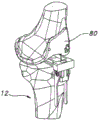
FIG. 1 is a sagittal view of the distal portion of the femur.
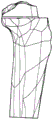
Fig. 2 is a perspective view of the proximal portion of the tibia.
Fig. 3 is a sagittal view of the distal femur of fig. 1 after a distal osteotomy.
Figures 4 and 5 show a distal femoral trial positioned against the resected surface of the distal femur of figure 3.
Figure 6 is a perspective view of the distal femoral trial of figures 4 and 5.
Figures 7 a-7 f show several anterior and sagittal views of a femoral implant, an inferior portion of the femoral implant, and a distal femoral trial.
Figure 8 shows a distal femoral trial positioned in the joint space between the distal femur and the proximal tibia.
Figure 9 schematically shows the use of a distal femoral trial to gauge flexion contracture.
Figures 10-14 illustrate various kits for distal femoral trials.
Figures 15-20 illustrate various arrangements of a distal femoral trial and the use of such a distal femoral trial as a gauge.
FIG. 21 is a sagittal view of the distal portion of the femur after a box-shaped bone cut.
Figure 22 is a sagittal view of a femoral trial positioned on the distal femur after the box-shaped bone cut of figure 21.
Fig. 23-29 illustrate various methods and instruments for removing a grooved portion of a distal femur.
Fig. 30 shows the distal femur after osteotomy and the proximal tibia that has not yet been prepared.
Figure 31 illustrates another use of the distal femoral trial.
Figure 32 illustrates another use of the distal femoral trial.
Figure 33 shows another use of the femoral trial.
Fig. 34a to 34g are various views of the alignment block.
Fig. 35 and 36 show another embodiment of an alignment block.
Fig. 37 a-37 e are various views of an extramedullary rod connector.
Fig. 38 shows the alignment block of fig. 34 pinned to the proximal tibia and an extramedullary alignment rod associated with the alignment block by the extramedullary rod connector of fig. 37.
Fig. 39 a-39 c show additional views of the alignment block of fig. 35.
Fig. 40a to 40e are various views of the auxiliary alignment block.
Fig. 41 to 43 show another embodiment of the auxiliary alignment block.
Fig. 44a to 44c show another embodiment of the auxiliary alignment block.
Figures 45 a-45 c show various views of the medial tibial resection guide.
Figures 46-48 illustrate other embodiments of the medial tibial resection guide.
Fig. 49a to 49e show various arrangements of the fingers.
Other finger embodiments are shown in figures 50 and 51.
Fig. 52a and 52b show two examples of tibial implant footplates.
Fig. 53 and 54 show an alignment block pinned to the proximal tibia and an extramedullary alignment rod associated with the alignment block by an extramedullary rod connector.
Fig. 55-59 illustrate various methods for locating, repositioning, adjusting and/or checking the position and/or orientation of various embodiments of an alignment block on the proximal tibia.
Figures 60-74 illustrate various methods for positioning, repositioning, adjusting and/or checking the position and/or orientation of various embodiments of the medial tibial resection guide and stylus relative to the proximal tibia.
Fig. 75-87 illustrate various methods and apparatus for creating a plateau and/or spine osteotomy on the proximal tibia.
Fig. 88-98 illustrate various methods and instruments for evaluating a medial plateau resection on the proximal tibia.
Figures 99-107 illustrate various methods and apparatus for making a lateral plateau resection on the proximal tibia.
Fig. 108-112 show various views of a tibial trial baseplate.
Fig. 113-159 illustrate various instruments and methods for punching a keel cavity in a proximal tibia, removing an anterior portion of an eminence on the proximal tibia, and gauging clearance around the eminence of the resected proximal tibia.
Fig. 160-162 show an alternative embodiment for making a vertical spine resection on the proximal tibia.
Detailed description of the drawings
The following description of the non-limiting embodiments as illustrated in the figures is merely exemplary in nature and is in no way intended to limit the invention, its application, or uses disclosed herein. Fig. 1-30 show examples of methods and instruments for preparing a distal femur for a femoral implant during knee arthroplasty. Fig. 31-162 illustrate examples of methods and apparatus for preparing a proximal tibia for a tibial implant during knee arthroplasty.
Femur osteotomy
There is a strong relationship between the femoral attachment location of the soft tissue and the articulation between the tibia and the femur. In general, it can be seen that for knee implant designs that rely more on artificial motion control and stability devices than natural soft tissue structures, the patient's motion effects are less sensitive to mismatches between, for example, the superior/inferior locations of the natural femoral articulation and the implanted femoral articulation, although such mismatches may still be extremely important in some circumstances. However, as more natural structures are retained (e.g., with a double-crossing retaining implant) in order to provide motion control and stability, retention of the femoral connecting line (joint line) may become more important to the patient outcome, at least in some cases.
It is now common practice to prefer to resect the distal femur to the level of the trochlear (trochlea), rather than by measuring the depth of the resection from the medial femoral condyle. However, in at least some instances, it may be preferable to utilize methods and instruments that prevent any tendency for resection of the distal femur at a level different from the thickness of the distal femoral implant. For example, it may be preferable to resect an amount equal to the thickness of the distal femoral implant as measured from the distal medial (and/or lateral) condyle, which may better account for the mesial attachment site of the posterior and/or anterior cruciate ligaments on the femur. It may also be preferable in at least some instances to utilize methods and apparatus that allow for early testing and assessment of stretch space and relaxation (laxity). Certain examples of these methods and apparatus are described below.
Some of the methods discussed below also reduce the complexity of the knee arthroplasty procedure (composition) by not simultaneously solving the femoral and tibial degrees of freedom, but by preparing the femur first and then the tibia. By completing all femoral resections prior to tibial resection, the surgeon has a set of fixed values from which he or she can determine the remaining tibial degrees of freedom. Another benefit of preparing the femur first provided by some of the methods described below is that they ensure proper kinematics (kinematics). To achieve proper motion performance, the femoral implant should generally conform to and articulate well with the natural anatomy (e.g., natural soft tissue and natural tibial cartilage). By separating the femoral resection step from the tibial resection step, the surgeon has no other input variables available for making femoral resection decisions in addition to the input variables provided by the natural femoral anatomy.
In certain embodiments discussed below, a third benefit of preparing the distal femur before the tibia is that even after the femoral side has been prepared, the surgeon has the flexibility to perform a posterior stable cross-preservation or double cross-preservation surgical procedure with little or no time loss (penalty) or bone loss.
However, many of the methods and instruments described below are not limited to femoral prior art techniques, or to techniques that achieve all of the above benefits.
Fig. 1-9 illustrate a method and apparatus for first cutting a distal bone for performing such a method in connection with the distal femur 10 shown in fig. 1 and the proximal tibia 12 shown in fig. 2.
Fig. 1 shows a distal femur 10 prior to osteotomy. Fig. 3 shows the distal femur 10 after an osteotomy is used to define the resected surface 14 on the distal femur 10. In some embodiments, the resected surface 14 is at a depth approximately equal to the distal thickness of the femoral implant 16 ultimately implanted on the distal femur 10. One non-limiting example of a suitable femoral implant 16 is shown in fig. 7a and 7 d. The distal femoral resection may be performed using conventional or non-conventional techniques and instruments. For example, a conventional cutting block (not shown) may be pinned to the distal femur using an intramedullary canal to navigate to and/or using one or more (e.g., two) parallel pins to guide a reciprocating saw or an oscillating saw or other cutting device to make the distal femoral osteotomy. In some cases, it may be desirable to retain the pin on the distal femur 10 if it becomes necessary to reattach the same cutting block or a different cutting block in order to resect the distal femoral resection.
Figures 4-8 illustrate insertion of the distal femoral trial 18 and the distal femoral trial 18 between the resected surface 14 on the distal femur 10 and the resected surface on the proximal tibia 12 (e.g., the resected surface 20 on the proximal tibia 12 shown in figure 2). As shown in fig. 4-8, the distal femoral trial 18 includes an upper flat surface 22 and a lower curved surface 24. The superior facet 22 is configured for contact with the resected surface 14 on the distal femur 10. The lower curved surface 24, including the medial condyle surface 26 and the lateral condyle surface 28, is for contact and at least some articulation with the resected surface 20 on the proximal tibia 12. The superior facet 22 may be flat, smooth, or textured to improve friction with the bone forming and surrounding the resected surface 14 on the distal femur 10. As shown in fig. 7 a-7 f, the distal femoral trial 18 of fig. 4-8 substantially replicates at least some of the shape and thickness defined by the femoral implant 16, and in particular at least some of the inferior portion 30 (shown in fig. 7c and 7 e) of the femoral implant 16.
In the embodiment illustrated in fig. 4-8, the femoral implant 16 and the distal femoral trial 18 are designed for a bicruciate retaining surgical procedure. For example, as shown in fig. 6, the distal femoral trial 18 is substantially U-shaped and defines a gap 38 between the medial and lateral condyle surfaces 26,28 for receiving at least a portion of a tibial eminence 40 of the proximal tibia 12 (shown in fig. 2). The tibial eminence 40 includes attachment sites for the anterior and posterior cruciate ligaments. The gap 38 of the distal femoral trial 18 is sized and positioned to avoid substantial interference of those ligaments as the distal femoral trial 18 is inserted between the resected surface 14 of the distal femur 10 and the resected surface 20 of the proximal tibia 12, an example of which is shown in fig. 8.
The illustrated distal femoral trial 18 also includes an attachment site 32 for attaching various tools and other instruments (see FIG. 6). For example, as shown in FIG. 8, the attachment site 32 may be used to connect a handle 34, which in turn may be used to connect other tools, such as an extramedullary alignment rod 36 as shown. As shown in fig. 6, the attachment location 32 may include a geometry (e.g., without limitation, a non-circular geometry) that allows an item, such as the handle 34, to be secured in a fixed angular position (e.g., without rotation). Other mechanisms may also be employed with respect to the attachment location 32 to secure an article thereto in a fixed angular position. For example, the attachment site 32 may facilitate the attachment of fiducial structures (fiducials) used in certain computer assisted surgical knee surgical procedures. Examples of other tools and other instruments that may be connected to attachment site 32 are discussed further below.
Figures 8 and 9 illustrate one approach by which the distal femoral trial 18 may be used to assess distal femoral osteotomies. Figure 8 shows the distal femoral trial 18 inserted into the gap between the resected distal femur 10 and the resected proximal tibia 12. Although not explicitly shown in fig. 8, the distal femur 10 and the proximal tibia 12 of the knee joint are connected together by anterior and posterior cruciate ligaments and other anatomical structures such as medial collateral ligaments (medial collateral ligaments), lateral collateral ligaments and patellar tendon (patellar tendon). By inserting the distal femoral trial 18 into the joint space, the surgeon may evaluate the distal femoral resection.
For example, if the distal femoral trial 18 is a trial that substantially replicates, at least in some geometric aspects, the shape and thickness of the inferior portion 30 of the femoral implant 16, and if the resected surface 14 on the distal femur 10 has been cut to a depth approximately equal to the distal thickness of the femoral implant 16, the surgeon may assess the expected tension or relaxation of the knee joint once the surgical procedure is completed and the femoral implant 16 is implanted (taking into account the tension or relaxation of one or more of the ligaments and tendons described above), and/or may assess flexion contracture.
Figure 9 schematically shows how the surgeon can assess flexion contracture of the knee joint. In the technique illustrated in fig. 9 (which schematically illustrates the positioning of the distal femur 10 relative to the proximal tibia 12), once the distal femoral trial 18 is inserted between the distal femoral resection and the resected proximal tibia, the knee joint may be extended to the maximum extension permitted by the knee joint. If the maximum allowable degree of extension is less than the desired degree of extension, less than that of a natural, healthy knee, and/or less than that of the patient's knee prior to surgery (as schematically shown by dashed line 300 in FIG. 9), then it may indicate to the surgeon some flexion contracture and indicate that the distal femur requires a deeper osteotomy (i.e., the knee is "too tight"). In this case, the cutting block may be reattached and the distal femoral resection may be resected for re-evaluation with the same or a different distal femoral trial. If the maximum extension is sufficient (as schematically shown by dashed line 302 in fig. 9), it may indicate to the surgeon that the level of distal femoral resection is sufficient and no resections are required. It should be appreciated that while the boundary between flexion contracture and sufficient extension (as schematically illustrated by solid line 304) is shown in fig. 9 to occur at approximately 0 degrees of flexion, the boundary need not be so located and may be at more or less than 0 degrees of flexion depending on the patient's particular circumstances or other factors.
One advantage of the embodiment of the distal femoral trial 18 shown in figures 4-9 is that it can be used without the need to resect the tibia. Many conventional spacer blocks (spacer blocks) used in gap balancing and other osteotomy assessments in knee arthroplasty procedures require at least one osteotomy of both the tibia and the femur in order to function properly. On the other hand, the distal femoral trial 18 shown in fig. 4-9 facilitates evaluation of the resected surface 14 on the distal femur 10 relative to the non-resected surface 20 on the proximal tibia 12, and thus provides information about the level of osteotomy in absolute terms. Because conventional spacers measure femoral resections relative to tibial resections, they can only provide information about the spacing between the resections, not the orientation and position of the femoral resection relative to the connecting lines of other important anatomical structures of the knee joint.
Thus, in a method in which at least one, if not all, of the femoral resections are made prior to resection of the proximal tibia, the distal femoral trial 18 of figures 4-9 may be used to provide information regarding the level of the distal femoral resection earlier in the surgical procedure than a conventional spacer. Obtaining this information earlier in the surgical procedure reduces the likelihood of delivery errors (propagtingerros), which may lead to poor outcomes and increased surgical time.
Another advantage of the method illustrated in fig. 4-9 over many conventional techniques that utilize conventional spacers is that these conventional techniques and pads may produce "false slack" in the stretch interval. For example, after the posterior condyle has been resected, when checking flexion and extension gaps with a conventional spacer, false relaxation in extension may be common because, in some cases, the posterior portion of the condyle provides some tension to various anatomical structures that constrain and interact with the knee joint. By utilizing the distal femoral trial provided herein, the user is forced to gauge extension laxity in the environment most likely to give the correct feedback.
It will be appreciated by those skilled in the art that the methods and apparatus described above may be used to assess distal femoral osteotomies in other ways. For example, in certain embodiments, the distal femoral trial 18 may allow a surgeon to assess the suitability of a double-crossover retention implant and the surgical procedure for a particular patient at an early stage of the surgical procedure (e.g., prior to other substantial osteotomies or disruptions (disfigurements) being performed on the patient's anatomy), or whether a post-crossover retention, double-crossover sacrificial (e.g., for a post-stabilization implant), or other implant/surgical procedure should be performed instead. In conjunction with the above or other evaluation techniques, the distal femoral trial 18 may be associated with a handle 34 and an extramedullary alignment rod 36 (such as shown, for example, in fig. 8) to facilitate visualization of mechanical and anatomical alignment. In still other embodiments, distal femoral trials different from those that replicate or substantially replicate the intended femoral implant may be used to otherwise assess a distal osteotomy or other aspect of the knee joint.
In some embodiments, such as the embodiments shown in fig. 31-33, the distal femoral trial 18 or other types of femoral trials may be advantageous in determining the appropriate depth on the proximal tibia 12 for osteotomy. Fig. 31 shows a tibial depth gauge 98 attached to the handle 34 for marking indicia 100 on the proximal tibia 12 (using a surgical marker or other instrument) to indicate a desired depth of tibial resection or other information relating to knee arthroplasty. Although not shown, in some embodiments, it may be desirable to attach an extramedullary alignment rod 36 or other alignment facilitating device to ensure that the knee joint is at the proper level of extension or flexion or otherwise properly aligned prior to marking with the indicia 100.
Figures 32 and 33 illustrate other instruments that may be used with the distal femoral trial 18 (figure 32) or another femoral trial 80 (figure 33) to indicate tibial depth. Figure 32 shows the alignment block 102 attached to the distal femoral trial 18 by the associated handle 34. The alignment block 102 may be used to mark indicia on the proximal tibia 12 or, in some embodiments, may be directly pinned to the proximal tibia 12. Because the connection between the distal femoral trial 18 and the alignment block 102 positions the alignment block 102 in a fixed angular position relative to the distal femoral trial 18, the position of the distal femoral trial 18 and its associated handle 34 (and at least to some extent the degree to which the knee joint is in flexion or extension) will control the positioning and orientation of the alignment block 102 relative to the proximal tibia 12, such as its superior/inferior positioning, its varus/valgus angulation, and its posterior slope angle. However, movement of the knee joint through flexion/extension may at least partially affect some of these positions and orientations of the alignment block 102 relative to the proximal tibia 12. Thus, in some embodiments, it may also be desirable to use the extramedullary alignment rod 36 (shown in fig. 8) or the indicator 104 (shown in fig. 32) to confirm proper and/or desired positioning of the alignment block 102 on the proximal tibia 12.
Figures 10-13 illustrate embodiments of a surgical kit including a different set 42 of distal femoral trials 18. For example, figures 11a through 11c schematically illustrate a set 42 of distal femoral trials 18 that simulate different femoral implant sizes. The illustrated set includes three sizes of distal femoral trials 18: first, for simulating a femoral implant having a medial-lateral width size of 1-2 and a 9.5mm medial condyle thickness; second, for simulating a femoral implant with a medial-lateral width size of 3-8 and a 9.5mm medial condyle thickness; and a third for simulating a femoral implant with medial-lateral width sizes 9-10 and 11.5mm medial condyle thickness. In some embodiments, the condyle radius of each distal femoral trial 18 may generally equal the average of each condyle radius within the size range. For example, size 1-2 distal femoral trials may have medial and lateral condyle radii that are approximately equal to the average of the medial and lateral radii of size 1 and size 2, respectively. In other embodiments, the condyle radius of the distal femoral trial may generally be equal to the smallest or largest condyle radius within a particular femoral implant size range. For example, the second distal femoral trial 18 (representing femoral sizes 3-8) may have medial and lateral condyle radii that are approximately equal to the medial and lateral condyle radii of the size 3 (minimum in the size range) or size 8 (maximum in the size range) femoral implant.
In another example, a set of distal femoral trials 18 are provided in a surgical kit, each having dimensions that correspond exactly to the dimensions of a particular femoral implant. In this example, more distal femoral trial may need to be provided to the surgical kit. However, if each distal femoral trial represents a single femoral implant size, then there is no need to average the medial and lateral distal radii or select the medial-lateral width in order to represent the entire size range with a single distal femoral trial. Thus, the assessment of slack and maximum extension may be done more accurately at the expense of providing a greater number of distal femoral trials for the surgical kit.
Figure 10 shows a set 42 of modular distal femoral trials 18. In the embodiment of fig. 10, each distal femoral trial 18 includes a base plate 44 that is attachable to a pair of modular shims 46 to form a particular sized distal femoral trial 18.
Fig. 12 and 13 show a modular distal femoral trial set that uses a base plate 44 and shim 46 to alter the specific geometry of the distal femoral trial 18. For example, in the embodiment of figures 12 a-12 h, the shim 46 facilitates modifying the thickness of the medial and lateral condyle portions of the distal femoral trial. In some applications, the modular distal femoral trial set shown in fig. 12 may be useful in evaluating distal femoral osteotomies while accounting for cartilage and bone defects, abnormalities, or other deviations (or particular morphology of the patient's femoral condyles) in the articulating surfaces of the tibia and/or femur. Figures 13 a-13I illustrate a set of modular distal femoral trials in which the modular base plate 44 may be used to change the overall thickness of the distal femoral trial and, or alternatively, to change certain angular geometries of the distal femoral trial, such as the varus/valgus angle or flexion/extension angle of the distal femoral trial. Figures 14 a-14 d show another example of a set of distal femoral trials in which the base plate 44 itself may be modular, allowing the medial and lateral portions of the base plate to be varied independently of the other portions. In some embodiments, the baseplate 44 shown in fig. 14 a-14 d may be used independently (e.g., only medial or only lateral) for various purposes, such as for unicondylar knee arthroplasty.
In still other embodiments, the distal femoral trial may include an adjustment mechanism that allows portions of the distal femoral trial to expand and/or contract relative to other portions to adjust the size, thickness, angular geometry, or other geometry of the distal femoral trial.
As shown in fig. 15-20, in some embodiments, the distal femoral trial 18 may be used as a gauge for gauging and/or setting the internal/external rotation, anterior/posterior position, and/or size of the distal femoral trial 18 relative to the resected surface 14 on the distal femur 10. Such a gauge function may facilitate visualization or planning by the surgeon on how the femoral implant 16 will be positioned and oriented on the distal femur 10 at the end of the surgical procedure.
The distal femoral trial 18 shown in figures 15-20 includes various references that indicate the position of the distal femoral trial 18 relative to the distal femur 10 and the resected surface 14 on the distal femur 10. For example, the trailing edge 48 of the lower curve of the distal femoral trial 18 may be used to reference the trailing edge 50 of the resected surface 14 on the distal femur 10 (as shown in fig. 17). The fin wings 56 may extend substantially perpendicularly from the posterior portion of the distal femoral trial 18, thereby referencing the posterior portions of the medial and lateral condyles 58 of the distal femur 10. A window 52 extending through the distal femoral trial 18 may be used to reference the medial and lateral epicondyle (epicondyle)54 of the distal femur 10. The additional window or windows 60 may be used to indicate the location of the distal femoral trial 18 relative to the AP axis 62 of the distal femur 10 and/or the central anterior V-point 64 of the resected surface 14 on the distal femur 10. Other references, such as markings on the distal femoral trial, may also be used independently or in combination with the window, fin, and other references described above. In some embodiments, the anterior surface or edge of the distal femoral trial 18 may be used to reference the anterior edge of the distal femoral resection 14.
In certain embodiments, the trailing edge 48, the window 52, the fins 56, the window 60, and/or other references (in various combinations) may be used to gauge the medial/lateral rotation of the distal femoral trial 18 relative to the distal femur 10, which in certain instances may be used to visualize and/or plan the final positioning of the femoral implant 16 on the distal femur 10.
The distal femoral trial 18 shown in figures 15-20 may also be used to gauge femoral size and AP position. Many of the same references, such as trailing edge 48, finstock 56 and window 60 may be used for gauge size and location. Other references on the distal femoral trial may also be useful, such as, for example, the relative positions of the medial and lateral edges 66 of the distal femoral trial 18 relative to the medial and lateral edges 68 of the resected surface 14, or the relative positions of the deployable arm(s) 70 (or markers not shown on the deployable arm (s)) relative to the medial and lateral edges 68, which may be useful in determining or evaluating medial-lateral sizing of the femoral implant. As shown in fig. 19 and 20, the anterior stylus 72 may be associated with the distal femoral trial 18 (in the embodiment shown in fig. 19 and 20, by positioning the anterior stylus 72 on the attachment site 32 of the distal femoral trial 18) to reference the location of the anterior cortex 74 of the distal femur 10.
Once the desired position and/or rotation of the distal femoral trial 18 relative to the distal femur is achieved, the surgeon may create markings on the distal femur as necessary to record this information for future use in the surgical procedure. For example, the distal femoral trial 18 shown in figures 15-20 includes an opening 78 to receive a bone pin, surgical marker, or cutting device that may mark or place indicia on the distal femur.
In some embodiments, after completing assessment of the relaxivity and extension or other aspects of the distal femoral resection, as shown in fig. 21, a conventional "box-shaped bone cut" may be provided for the distal femur 10. The box-shaped bone cut can be created by: placing a five-in-one cutting block on the distal femur osteotomy, making a posterior bone cut for the medial and lateral condyles, making a posterior chamfer bone cut for the medial and lateral condyles, making a anterior bone cut for the distal femur, and making an anterior chamfer bone cut; and then, if appropriate, an anterior "roll-on bone cut" is made on the distal femur 10 between the anterior chamfer bone cut and the anterior bone cut. The roll-on osteotomy generally allows femoral components having converging posterior and anterior bone cuts to be easily implanted without binding. In some embodiments, markings created on the distal femur 10 using the metrology function of the distal femoral trial 18 may be used to locate the five-in-one cutting block.
Figure 22 shows a femoral trial component 80 mounted on the distal femur 10 having a bone engaging surface that mates with the box-shaped bone cut. The femoral trial member 80 may be provided with a femoral cutting guide configured to receive and guide a notch cutter (as described below with respect to figures 23-28), another type of cutter (as described below with respect to figure 29), or other features discussed further below. In certain embodiments, such as the embodiment shown in fig. 23-25, the femoral cutting guide is a separate member 82 that may be secured relative to the femoral trial member 80 (such as shown in fig. 23-25 and 29). In other embodiments (such as shown in fig. 26-28), the femoral cutting guide is an integral part of the femoral trial member 80. In certain embodiments (not shown), the femoral cutting guide may be a separate component that is not used with the femoral trial component 80.
In the embodiment shown in fig. 23-25, the femoral trial 80 and member 82 are used in conjunction with a notch cutter 84 to remove a distal grooved portion of the distal femur 10 adjacent to the ACL and PCL. Figures 26-28 show a femoral trial 80 with an integrated femoral cutting guide for use with a notch cutter 84. The pocket cutter 84 shown in the figures is an elongated chisel extending along a longitudinal axis 86 (see, e.g., fig. 24) and including a leading cutting edge 88. The front cutting edge 88 has an inboard portion 90, an outboard portion 92, and a central portion 94 located between the inboard and outboard portions. The central portion 94 is substantially recessed into the notch cutter, which in some embodiments may reduce the force required to cut the distal channel portion, while also reducing the chance that the anterior or posterior ligaments may be damaged during an osteotomy (see, e.g., fig. 28). The notch cutter 84 shown in the figures forms a U-shaped or V-shaped front cutting edge, although other shapes are possible.
The notch cutter 84 shown in the figures includes a flange 96 that extends substantially parallel to the longitudinal axis 86 of the cutter. The flange 96 may interact with a channel, groove, or other structure on the femoral trial 80 or the separate member 82 to guide and/or limit the movement of the notch cutter 84 along the longitudinal axis. In certain embodiments, structures and/or the tip of the flange incorporated into the femoral trial 80 or separate component 82 are used to limit longitudinal movement to prevent the notch cutter 84 from cutting too deeply.
Fig. 29 shows that other types of cutters and cutting guides can be used to cut the distal flute portion. Fig. 30 shows the distal femur 10 once all of the above osteotomies have been completed.
Tibia osteotomy
One problem faced when performing a double cross-conserving TKA surgical procedure, which may be important for at least some of the embodiments described herein, is the complexity of tibial osteotomies. This complexity stems from at least two factors associated with retaining the cruciate ligament.
The first factor is that there are more significant degrees of freedom associated with the double cross-sparing arthroplasty procedure than typical posterior stability or PCL-sparing arthroplasty procedures. In total knee arthroplasty, for example, objects such as osteotomy guides and other instruments have 6 degrees of freedom in three dimensions, including three translational degrees of freedom and three rotational degrees of freedom. At least three additional variables or "morphologies" are equally applicable in TKA surgical procedures, including femoral implant size, tibial implant size, and tibial insert thickness. For posterior stability or cross-preservation arthroplasty procedures, only three degrees of freedom (1 translational degree of freedom and 2 rotational degrees of freedom) are generally considered important. For many (although not necessarily all) double-cross-retaining arthroplasty procedures, there are at least three additional degrees of freedom (i.e., 1 translational degree of freedom, 1 rotational degree of freedom, and 1 "modality") that are considered important. These three additional degrees of freedom are due to the constraints imposed by the retaining spine to which the cruciate ligament is attached.
A second factor of potential relevance is that bicruciate retaining knee arthroplasty requires precise surgical techniques. The trade-off with the double-crossover retention technique is the risk of mechanical complications due to increased surgical complexity (e.g., stiffness or implant loosening) in exchange for a healthier post-operative patient mobility and function. The additional degrees of freedom necessary to perform a successful bicruciate retaining surgical procedure require greater precision than traditional posterior stability or posterior cruciate retaining total knee arthroplasty.
Proper control and management of the above degrees of freedom during surgery, as well as other factors, is one of the key factors in clinically and commercially successful double cross-sparing arthroplasty. Clinical success often times depends on the surgeon's ability to accurately and properly implant a well-designed prosthesis to achieve the advantages provided by the well-designed prosthesis. Commercial success often times depends on the ability of the surgeon to implant a well-designed prosthesis with confidence and rapidity, with precision, and with the right. Some, although not necessarily all, of the embodiments described herein address these issues.
As previously described, in all knee arthroplasty procedures, the risks associated with tibial osteotomy degrees of freedom (i.e., varus/valgus angle, posterior slope angle, and osteotomy depth) are greater for a double cross-preserving arthroplasty procedure than for a posterior stability or posterior cross-preserving procedure. This is because the varus/valgus angle, posterior slope angle and osteotomy depth directly affect the operation of the cruciate ligaments in guiding the movement of the joint. Furthermore, as previously described, the risks associated with additional degrees of freedom specifically for bicruciate retaining arthroplasty (particularly the medial/lateral rotational angle and the medial/lateral position of the tibial plateau and the osteotomy) may include serious losses due to errors, including but not limited to compromised tibial intercondylar eminence structural integrity, impaired joint motion, and/or impaired cortical ring coverage. Any degree of freedom related error in the 5 degrees of freedom associated with a bicruciate retaining type procedure may lead to complex decision-making for the surgeon (e.g., better than achieving the best possible cortical coverage than providing the greatest degree of retention of the tibial eminence and its anterior and posterior cruciate ligament attachment sites). This decision may be, for example, whether to re-cut the bone to correct the perceived error, or simply to retain the error. The re-cut decision facilitates an increase in time and complexity and may subsequently increase the likelihood of delivering more errors.
The embodiments of the bicruciate retaining tka techniques and instruments described herein present a truly complex surgical procedure to the surgeon in a simplified form by taking into account discreet anatomy, compactness, and readily available information. As will be discussed below, these embodiments may provide, in part, an improved method of preparing a proximal tibia during a total knee arthroplasty and instruments therefor. The method and apparatus described below can be broadly divided into three stages: controlling the degree of freedom; making a osteotomy; and subsequently a finishing step is performed.
Controlling the degrees of freedom may typically include one or more of the following: the method includes the steps of roughly setting tibial resection depth, setting a neutral (or baseline) varus/valgus angle for medial and lateral tibial plateau resections, setting a neutral (or baseline) caster angle for medial and lateral tibial plateau resections, fine-tuning the caster angle and/or varus/valgus angle for medial and lateral tibial plateau resections, setting medial-lateral positioning of medial and lateral eminence cuts, setting a medial-lateral rotation angle for medial and lateral eminence cuts, determining a suitably sized tibial eminence width (related to implant size), if desired, and fine-tuning the depth for medial and lateral tibial plateau resections.
Making an osteotomy may generally include one or more of the following steps: the method includes the steps of making a medial tibial plateau resection, making medial and lateral tibial intercondylar eminence bone cuts, performing medial plateau balance examination, performing lateral tibial plateau resection, and performing trial reduction to assess range of motion, joint stability, and soft tissue tension.
The finishing step may also typically include one or more of the following: the method includes the steps of punching a keel cavity into cancellous bone of a proximal tibia, making an anterior eminence bone cut and an anterior tibial plateau resection to remove an anterior block portion of a tibial eminence, removing bone at a spinous corner, and implanting a tibial component.
1. Degree of freedom control
This section begins with the introduction of certain instruments and other instruments and certain aspects of their structure and design for controlling tibial degrees of freedom in accordance with certain knee arthroplasty methods discussed herein. The latter part of this section discusses non-limiting examples of how those instruments and other instruments may be used to control the tibial degrees of freedom.
a. Alignment block
Fig. 34 a-34 g show various views of the alignment block 102, which may be used as a basic instrument in some embodiments to provide such a neutral/reference tibial base. The alignment block 102 includes a body 106 through which a number of pin receiving openings 108 extend to pin the alignment block 102 to the proximal tibia 12. The alignment block 102 also includes a seat plate 110 with a seat plate connector 112 positioned above the body 106. The bulkhead connector 112 shown in fig. 34 a-34 g is substantially planar and, as shown particularly in fig. 34a and 34c, includes a plurality of indexing features 116, the purpose of which will be described further below.
The alignment block 102 shown in fig. 34 a-34 g, particularly as shown in fig. 34 d-34 f, allows for adjustment of the bench connector 112 in the superior and/or inferior direction relative to the proximal tibia 12. As shown in fig. 35 and 36 (which show slightly different alignment block 102 embodiments), the alignment block 102 may include set screws 114 that may be loosened or tightened to allow adjustment of the seat plate 110 in the up and down directions, respectively. As also shown in fig. 35 and 36, portions of the seat plate 110 can fit into and be guided by a channel or other structure in the body 106 to maintain alignment of the seat plate 110 relative to the body 106 as the seat plate 110 slides in the up and down directions. In other embodiments, other structures and mechanisms may be employed in addition to or in place of the structures and mechanisms shown in fig. 35 and 36 to guide the movement of the seat plate 110 relative to the body 106 and to selectively fix the position of the seat plate 110 relative to the body 106.
Fig. 37-39 show an instrument for connecting the extramedullary alignment rod 36 to the alignment block 102. Fig. 37 a-37 e show various views of an extramedullary rod connector 118 that may be temporarily associated with the alignment block 102, for example as shown in the embodiment shown in fig. 38. The extramedullary rod connector 118 includes a recess 120 and a hole 124, the recess 120 being sized and aligned to receive the flat bench connector 112 of the alignment block 102, the hole 124 being sized and aligned to receive the alignment rod 36, which may be secured in the hole 124 by a thumbscrew mechanism 126. The groove 120 includes a spring tensioner 122 that helps maintain and maintain the angular alignment of the extramedullary rod connector 118 relative to the seat plate connector 112 (i.e., maintain the alignment of the extramedullary rod connector 118 on the flat seat plate connector 112 such that the extramedullary rod 36 held by the extramedullary rod connector 118 is substantially perpendicular to the flat seat plate connector 112) in addition to or in place of the geometry of the groove 120 itself.
In the embodiment shown in fig. 37 and 38, the geometry and structure of the flat seat plate connector 112, the groove 120, and/or the spring tensioner 122 allows for sliding translation and/or rotation of the extramedullary rod connector 118 relative to the flat seat plate connector 112 in several degrees of freedom while maintaining a substantially perpendicular alignment of the extramedullary rod 36 relative to the flat seat plate connector 112. In certain embodiments, such adjustability of the extramedullary rod 36 relative to the alignment block 102 may advantageously allow the extramedullary rod 36 to be aligned with an axis and/or feature of the proximal tibia 12 even though the alignment block 102 may deviate from such a feature. For example, in some cases, it may be desirable to align the extramedullary rod 36 along the longitudinal axis of the tibia at a tuberosity of the proximal tibia 12, while offsetting the alignment block 102 from such a tuberosity.
Alignment blocks and extramedullary rod connectors other than those shown in fig. 34 and 37 can also be used with the methods and instruments described herein. For example, the extramedullary rod connector 118 shown in fig. 37 or another type of extramedullary rod connector can be connected to other locations and to other structures on the alignment block 102. As another example, fig. 35,36 and 39 show an alignment block with an in-built connector for an extramedullary rod and with a differently shaped seat plate 110.
In some embodiments, the alignment block and the extramedullary rod connector can be a single piece, or a pair of components that function as a single piece, with one or both of the components including structure (e.g., pin receiving holes) for securing the alignment block and extramedullary rod assembly to the tibia. In some cases, the pin receiving hole or other fastening mechanism may define an elongated slot that allows adjustment in some degrees of freedom while constraining the assembly to the tibia in other degrees of freedom.
b. Auxiliary alignment block
Fig. 40 a-40 c show an adjustment instrument or auxiliary alignment block 128 that may be fastened to the alignment block 102 shown in fig. 34 a-34 g. The secondary alignment block 128 includes a first recess 130 and a second recess 132. The first recess 130 is sized and positioned to receive the flat panel connector 112 of the alignment block 102, and in some embodiments may be a receptacle structure having an alignment axis. As discussed below, the second groove 132 is sized and positioned to connect to a medial tibial resection cutting guide, or (in some embodiments) to connect with additional or other components.
In the embodiment of fig. 40 a-40 c, both the first groove 130 and the second groove 132 are associated with a spring tensioner 134, which in the case of the groove 130 may facilitate frictional engagement between the groove 130 and the seat plate connector 112, while still allowing translation and rotation of the auxiliary alignment block 128 relative to the alignment block 102 in certain degrees of freedom, but while maintaining other fixed alignment between the two blocks 102 and 128. A pair of pins 136 extend through at least the recesses 130, which in some embodiments may interact with the indexing features 116 of the dock connector 112 to help maintain a desired position and orientation of the secondary alignment block 128 on the dock connector 112.
Fig. 41-43 show another embodiment of a secondary alignment block 128 that may be attached to the alignment block 102, such as those shown in fig. 35,36, and 39. The secondary alignment block 128 of fig. 41 and 42 includes a recessed channel or other structure (not shown) to receive the T-shaped seat plate connector 112 of the alignment block 102 of fig. 35,36 and 39, which at least to some extent constrains the movement of this secondary alignment block 128 relative to the alignment block 102 of fig. 35,36 and 39. Instead, the secondary alignment block 128 itself is adjustable in certain degrees of freedom, which allows the upper portion 138 of the secondary alignment block 128 shown in fig. 42 a-42 c to rotate and translate relative to the lower portion 140 while maintaining alignment of the two portions in other degrees of freedom. As shown in fig. 43, this secondary alignment block 128 includes a pivot 142 and a lock 144 to facilitate rotational and translational adjustment of the upper section 138 relative to the lower section 140 and to fix the position and orientation of the upper section 138 relative to the lower section 140 once the desired position and orientation is obtained. The pivot 142 (which may be a screw or other mechanism) is positioned in a rectangular or oval track in the lower portion 140. The secondary alignment block 128 shown in fig. 41-43 also includes spring clips 190 (on upper, lower, or other surfaces) that, in some embodiments, may facilitate frictional engagement between the secondary alignment block 128 and other instruments and components, and/or between upper and lower portions 138,140 of the secondary alignment block 128 itself.
As these alternative embodiments illustrate, the particular manner in which the secondary alignment block 128 may be translated and rotated relative to the alignment block 102 is not necessarily important, and various structures and mechanisms may be used to facilitate adjustment in certain degrees of freedom (e.g., without limitation, translation and rotation in a single plane) while preserving other alignments between the alignment block 102 and the secondary alignment block 128 (e.g., without limitation, translations and rotations outside of the single plane). The embodiments shown in the figures create a "planar" joint that allows simultaneous and limited medial/lateral translation and medial/lateral rotation while maintaining other alignments, such as posterior slope angle and superior/inferior positioning. Although the illustrated embodiment includes a planar joint defined by a single connection between two members, other structures and mechanisms may be used to create a "virtual" planar joint having similar properties. The purpose of these structures and mechanisms for allowing adjustment in certain degrees of freedom (e.g., medial/lateral position and medial/lateral rotation) while limiting movement or rotation in other degrees of freedom is described further below.
Returning to the embodiment shown in fig. 40 c-40 e, the grooves 130 and 132 extend through the secondary alignment block 128 at a fixed angle relative to each other, and the secondary alignment block 128 may be part of a set of secondary alignment blocks 128 having different fixed angles (e.g., 0 degrees, 3 degrees, 5 degrees) between the two grooves 130 and 132, where such fixed angles are marked on the secondary alignment block 128 so that the surgeon and assistant can distinguish between the various blocks 128. As will be described further below, the different fixed angles allow the surgeon to select a desired fixed posterior slope angle for the plateau resection on the proximal tibia 12. Although not shown in the figures, the groove geometry of the secondary alignment block or other features of the secondary alignment block may be varied to allow for selection of a desired varus/valgus angle in addition to or as an alternative to selection of a desired posterior slope angle.
The secondary alignment block 128 shown in fig. 40 c-40 e limits the control of the backrake angle to only a few discrete limited options that are variable without the need for re-cutting in order to provide accurate and reproducible bone cuts with conventional surgical saw blades and other cutting blocks.
However, it is contemplated that the supplemental alignment block 128 may be provided with means for incrementally or infinitely adjusting the recline angle. Fig. 44 a-44 c illustrate one embodiment of an adjustable recline angle supplemental alignment block 128. Such embodiments may include markings 146 on the superior, inferior, and/or lateral portions of the lateral alignment block to provide the surgeon with information regarding minor variations in posterior slope angle. Indicia may include, but are not limited to, a series of marks, grooves, laser etching, color bands, printed symbols, and lines. The upper and lower portions of the auxiliary alignment block 128 shown in fig. 44 a-44 c are curved to allow these portions to be rotated relative to each other to adjust the rear tilt angle of the alignment block. Set screws or other suitable mechanisms may be included to secure the auxiliary alignment block in the desired back rake angle.
It is believed that with the time and experience of utilizing the disclosed double cross-over conservation surgical technique, the surgeon will begin to understand a limited number of options for setting the posterior slope angle and prefer a particular posterior slope angle for all surgical procedures based on whatever principles he or she employs and his or her own observations.
c. Medial tibia osteotomy cutting guider
Fig. 45 a-45 c illustrate one embodiment of a medial tibial resection guide 148 for attachment to a secondary alignment block 128, such as the secondary alignment block 128 shown in fig. 40 a-40 e. The medial tibial resection guide 148 shown in these figures includes a central body portion 150 that is configured as a support connection that will connect the medial tibial resection guide 148 to a correspondingly shaped connection feature or features on the secondary alignment block 128. In the particular example of the secondary alignment block 128 shown in fig. 40 a-40 e and the medial tibial resection cutting guide 148 shown in fig. 45 a-45 c, the second groove 132 of the secondary alignment block 128 receives a lower portion of the central body portion 150, and the groove 152 receives a portion of the secondary alignment block 128 positioned above the second groove 132. In some embodiments, the interaction between these structures and grooves of the two components may mean that the position and orientation of the medial tibial resection cutting guide 148 and the structures and components thereon will be constrained by the position and orientation of the secondary alignment block 128 in at least some degrees of freedom (such degrees of freedom including, for example, medial/lateral position, medial/lateral rotation, posterior slope angle, and tibial depth). The reasons for these constraints will be discussed further below.
The medial tibial resection guide 148 shown in fig. 45 a-45 c includes a medial cutting guide surface 154 for guiding a cutting or milling instrument to resect a medial portion of the proximal tibia 12. As shown in these figures, the medial cutting guide surface 154 is part of a slot that extends through the medial portion of the medial tibial resection guide 148, utilizing the superior and inferior surfaces to constrain cutter movement in the superior and inferior directions, although in other embodiments only a single non-captured cutting guide surface 154 may be necessary. The medial tibial resection guide 148 of these figures also includes a medial resection opening 156 and a lateral resection opening 158 for receiving a pin to secure the medial tibial resection guide 148 to the proximal tibia and for other purposes described further below. The openings 156 and 158 are oriented in substantially the same direction and angulation as the groove 152, and thus will be oriented in substantially the same direction and angulation as the secondary alignment block 128 shown in fig. 40 a-40 c when the medial tibial resection guide 148 is connected. As shown in fig. 45c, a line tangent to the bottom of openings 156 and 158 is generally coplanar with medial cut guide surface 154.
Fig. 46-48 illustrate an alternative embodiment of a medial tibial resection guide 148. Figure 46 shows a medial tibial resection guide that includes medial and lateral cutting guide surfaces. Figure 47 shows another possible arrangement for a medial tibial resection guide (including that which may also be used for a lateral resection), and different arrangements and locations for the resection openings are possible. Fig. 48 shows another possible arrangement for a medial tibial resection guide having a different structure for attaching the guide to a secondary alignment block or other component.
d. Contact finger
Figures 49 a-49 e illustrate a stylus 160 that may be used with many of the methods and apparatus described herein. The stylus 160 includes a body 162 for connecting the stylus 160 to other instrumentation, such as, but not limited to, the medial tibial resection guide 148 shown in fig. 45 a. In this particular embodiment, a groove 164 in the finger body 162 (with a spring tensioner positioned therein) is provided to receive a portion of the medial tibial resection guide 148 shown in fig. 45a, wherein an underside portion 166 of the finger body 162 protrudes into the groove 152 of the medial tibial resection guide 148. In such an embodiment, as shown for example in fig. 74, portions of the stylus body 162 and portions of the secondary alignment block 128 both protrude into the groove 152 of the medial tibial resection guide 148, creating a single assembly in which these components are in fixed positions relative to each other (in at least some translational and rotational degrees of freedom) and are simultaneously translatable and/or rotatable in at least some degrees of freedom. As shown, and as will be appreciated by those skilled in the art, other connector configurations are possible for creating similar or other assemblies of alignment blocks, cutting guides, and fingers. As described in further detail below, the various stylus embodiments may also be connected to other instruments, trial members, other instruments, or anatomical structures (associated with a knee arthroplasty procedure), rather than just the alignment block and cutting guide.
As shown in fig. 49a, the body 162 of the finger 160 defines a reference plane 168 and a connection axis 170. The illustrated stylus 160 also includes two indicator members 172 and 174 (shown in fig. 49 a-49 e) pivotally mounted to the body 162. In certain embodiments, the indicator members 172 and 174 are rotatable about the connection axis 170 in a plane substantially parallel to the reference plane 168, although in other embodiments, the indicator members 172 and 174 may be mounted on the body 162 in a fixed orientation and/or in a non-parallel orientation. Depending on the particular use of the stylus 160 (several uses of which are described below), the indicator members 172 and 174 may be used as alignment indicators, cutting guides (e.g., external guide surfaces 176 on one or both of the indicator members 172 and 174), attachment points for other instruments, or for other functions.
As mentioned earlier, three variables that may be dedicated to a double-cross-sparing surgical procedure are: 1) medial-lateral positioning of the spine osteotomy, 2) medial-lateral rotation of the spine osteotomy, and 3) spine width. These special variables can create a large learning curve for the surgeon to feel comfortable and competent during the surgical procedure.
For certain finger 160 embodiments discussed herein, the degrees of freedom reflected by the option for spine width may be significantly reduced, if not completely eliminated. From empirical measurements of the medial-lateral orientation of the anterior cross-attachment point, it has been determined that in some embodiments, the width of the spinous process can be set to one of two sizes. In certain embodiments, the two sizes of spine width may be approximately 19mm or 22mm, depending on the size of the tibial implant used (such as shown in fig. 52a and 52 b). Thus, in one example, if the tibial implant to be used in a surgical procedure has a size within a first size range (e.g., sizes 1-6), a first spine width (e.g., 19mm spine width) is used. In another example, if the tibial implant to be implanted has a size within a second size range (e.g., size 7-8) that is larger than the first size range, a larger second spine width (e.g., 22mm spine width) is used. It should be noted that more or less than the two dimensions and widths (rather than the explicitly recited ones) are contemplated, as are other widths for each particular dimension.
In the embodiment shown in the figures, the indicator members 172 and 174 extend substantially parallel to each other and define flat surfaces that are substantially parallel to each other and to the reference surface 168. In some embodiments, such as the embodiments discussed immediately above, the spacing of the two indicator members 172 and 174 may be defined by the width of a tibial eminence receiving gap 180 on a tibial baseplate 178 (such as the tibial baseplate 178 shown in fig. 52a and 52 b). In some embodiments, the stylus 160 may include modular indicator components in order to achieve different spacing between indicator components to conform to different dimensions of the tibial baseplate or for other reasons. As yet another alternative, different fingers may be provided that include differently spaced indicator members, or indicator members having different widths. In still other embodiments, the same indicator member may be used to guide saw blades of different widths simply by utilizing the inner and outer surfaces of indicator members 172 and 174.
Fig. 50 and 51 show an alternative embodiment of a stylus 160 having a slightly different arrangement and different mechanisms for attachment to other components. Other finger embodiments are possible. For example, in certain embodiments, the indicator member may include a capture groove or other structure for capturing rather than merely guiding the movement of a reciprocating cutter or other cutter mechanism.
As discussed further below, various embodiments of the stylus may be used as an alignment guide and/or cutting guide in a wide variety of settings, and in some embodiments the connector structure employed by the stylus may be required so that a single stylus may be connected to a wide variety of different instruments, components, and other knee arthroplasty instruments.
e. Positioning of alignment blocks
According to some embodiments, tibial preparation begins by first establishing a neutral/reference tibial base from which to begin the surgical procedure. The purpose of providing a neutral tibial base at an early stage in a surgical procedure is to roughly set two neutral degrees of freedom (i.e., neutral varus/valgus angle and neutral posterior oblique angle) before later fine tuning and/or setting other degrees of freedom. In some embodiments, the neutral basis may also roughly set other degrees of freedom, such as osteotomy depth. In at least some embodiments, providing a neutral tibial base generally serves as a good starting point for subsequent tibial preparation steps. In some embodiments, the positioning step of the alignment block 102 establishes a neutral tibial base. As used herein, a "neutral" or "reference" tibial base may include a base that sets a particular degree of freedom to zero degrees (e.g., zero degrees in varus/valgus or zero degrees of posterior slope), but may also include a "non-zero" neutral base in some embodiments.
As shown in fig. 53-59, the surgeon may position, orient, and secure the alignment block 102 in the proper position in a wide variety of ways.
Fig. 53 and 54 illustrate the use of the extramedullary alignment rod 36 and extramedullary rod connector 118 to position and orient the alignment block 102. In this embodiment, the longitudinal axis of the alignment rod 36 may be secured to the patient's ankle and aligned at least roughly parallel to the mechanical axis of the tibia (in one or both of the sagittal and coronal planes) on the tibial tubercle or elsewhere. Because the connection between the particular extramedullary rod 36, extramedullary rod connector 118, and alignment block 102 embodiments shown in fig. 53 and 54 will position the bench connector 112 of the alignment block 102 substantially perpendicular to the longitudinal axis of the alignment rod 36, when the alignment rod 36 is aligned roughly parallel to the mechanical axis of the tibia in the sagittal and coronal planes, the bench connector 112 will lie in a plane having zero varus/valgus angle and zero posterior slope angle relative to the tibia. As shown in fig. 53 and 54, the connection between these components also allows the alignment block 102 to be offset (in the medial or lateral direction) from the tibial tubercle while still being aligned in neutral varus/valgus and posterior slope angles. In the embodiment shown in fig. 53 and 54, the alignment block 102 is positioned with only a coarse focus (or no focus) on the precise superior/inferior positioning of the alignment block 102 relative to the tibial plateau, and such positioning may be addressed at a later point in time of the surgical procedure, for example by slidably adjusting the superior/inferior positioning of the socket connector 112 relative to the alignment block 102 or repositioning the alignment block 102 itself.
Fig. 55 shows an embodiment in which the up/down positioning of the alignment block 102 is considered at this stage of the surgical procedure. As shown in fig. 55, the alignment block 102 can be associated with both the extramedullary rod 36 and the auxiliary alignment block 128, wherein the extramedullary rod 36 facilitates positioning and orienting the alignment block 102 at neutral varus/valgus and retroversion angles, and the auxiliary alignment block 128 facilitates positioning the alignment block 102 at a desired superior/inferior position. For example, in the embodiment shown in fig. 55, the upper surface of the secondary alignment block 128 can be aligned with the marker 100 to set the alignment block 102 in a desired superior/inferior position on the proximal tibia 12. As discussed above and shown in fig. 31-33, the location for the marker 100 may be determined in various ways, which may correspond to a desired osteotomy depth for a medial and/or lateral tibial plateau osteotomy in some embodiments or a location having a fixed offset from the desired osteotomy depth in other embodiments, both of which may be determined based on the level of the distal femoral osteotomy in some embodiments.
In still other embodiments, such as shown in fig. 56, the desired superior/inferior position for the alignment block 102 may be set using a stylus 182 that references a structure of interest on the tibial plateau or the level of the tibial plateau. In still other embodiments, such as shown in fig. 57, the distal femoral trial 18 may be used to position and orient the alignment block 102 at least roughly at neutral varus/valgus and posterior slope angles and at desired superior/inferior positions. In such embodiments, it may be desirable (although not required) to use the extramedullary alignment rod 36 (e.g., by connecting it to the handle 34) to ensure that the alignment block 102 is properly positioned, particularly with respect to the posterior slope angle of the alignment block 102, since small angulations in flexion or extension of the distal femoral trial 18 may affect the posterior slope angle of the associated alignment block 102. Figure 58 illustrates a similar embodiment utilizing a femoral trial 80 to facilitate positioning and/or alignment of the alignment block 102.
Fig. 59 shows another embodiment for aligning the alignment block 102, which utilizes a double cross-shaped fin finger 184 to position and orient the alignment block 102 in cooperation with the extramedullary alignment rod 36. The double cross-shaped finfinger 184 may be placed on the medial and/or lateral portion of the unresectable proximal tibial plateau and used as a visual aid in setting the coarse medial-lateral position and coarse osteotomy depth of the alignment block 102. The positioning of the double cross fin fingers 184 and/or the alignment rod 36 relative to the alignment block 102 and the tibia 12 may be adjusted to determine and set the alignment rod 36 and the alignment block 102 in terms of the desired neutral varus/valgus angle and neutral posterior slope angle. Once these neutral angles are set, the alignment block 102 may be secured to the alignment rod 36 using a securing device, such as a cam and lever (as shown in fig. 35,36 and 39), a thumbscrew, a set screw, a spring-loaded ratchet or pawl, or an equivalent device provided on the alignment block 102 or a component associated with the alignment block 102. The alignment block 102 may then be secured to the anterior portion of the proximal tibia 12 (e.g., via a pinned connection) and may be used as a neutral tibial base for the remainder of the surgical procedure. After the alignment block 102 is pinned to the tibia 12, the double cross fin fingers 184 may be removed from the adjustable portion of the alignment block 102, and the alignment rod 36 may optionally be removed from the alignment block 102, tibia 12, and ankle, creating more room for the surgeon to work with.
f. Positioning of inside cutting blocks
In some embodiments, the next step in the tibial preparation is to position the medial cutting block (or combined medial/lateral cutting block) to guide one or more tibial plateau resections and (optionally) a vertical spine resection. In some cases, such as with a particular bicruciate retaining tibial implant, the degrees of freedom associated with the medial/lateral position and medial/lateral rotation of the platform and/or the vertical eminence bone cut may be highly interrelated such that in some embodiments, it may be preferable to set these degrees of freedom simultaneously. In some cases, setting these degrees of freedom separately can be an iterative and time-consuming process.
Fig. 60 shows one embodiment of a cutting guide assembly that includes an alignment block 102 that is pinned to the proximal tibia, with a secondary alignment block 128 mounted thereon, the secondary alignment block 128 in turn being coupled to a medial tibial resection guide 148 and a stylus 160. In this particular embodiment, the orientation of the alignment block 102 pinned to the proximal tibia 12 establishes the varus/valgus alignment of the various osteotomy guides provided by the medial tibial osteotomy guide 148 and the stylus 160. The orientation of the alignment block 102 also establishes the posterior slope angle of the medial tibial resection guide 148 in cooperation with the particular secondary alignment block 128 selected. The superior/inferior positioning of the flat bench connector 112 establishes the osteotomy depth for the tibial plateau and the vertical eminence osteotomy. For example, as shown in the various figures and embodiments described above and below, this is but one example of the many ways in which the various components described herein can be connected and used to control the various degrees of freedom of a tibial osteotomy.
In the specific embodiment of fig. 60, the medial/lateral position and medial/lateral rotation of the supplemental alignment block 128 relative to the planar seatplate connector 112 of the alignment block 102 establishes the medial/lateral position and medial/lateral rotation of the tibial plateau and the vertical eminence bone. The planar joint formed by the bench connector 112 and the first groove 130 (see, e.g., fig. 40 c-40 e) of the secondary alignment block 128 allows the secondary alignment block 128 (and thus the medial tibial resection guide 148 and the stylus 160) to translate and rotate in the plane defined by the bench connector 112 so that the medial/lateral position and the medial/lateral rotation of the secondary alignment block 128/medial tibial resection guide 148/stylus 160 assembly can be adjusted simultaneously, possibly avoiding the need for repeated adjustment of these two degrees of freedom independently of each other. The interaction between the indexing features 116 on the alignment block 102 (see, e.g., fig. 34a) and the pins 136 of the secondary alignment block 128 (see, e.g., fig. 40a), as well as the friction between the spring tensioners 134 of the secondary alignment block 128 (see also fig. 40a) and the flat bed connector 112 of the alignment block 102, may facilitate, at least to some extent, maintaining the position and orientation of the medial tibial resection guide 148/stylus 160/secondary alignment block 128 assembly (once placed in the desired position and orientation) prior to pinning the medial tibial resection guide 148 (or other component) to the proximal tibia 12.
As shown in fig. 61 a-61 d, the indicator members 172,174 on the stylus 160 may be used while adjusting the position and orientation of the secondary alignment block 128 to visualize the mesial position of the medial and lateral tibial plateau resections, as well as the medial/lateral position and medial/lateral rotation of the vertical tibial eminence resections (such resections will be discussed further below). This visual feedback to the surgeon may facilitate optimal positioning of the medial tibial resection guide 148 and the stylus 160 relative to the tibial eminence 40, the anterior and posterior cruciate ligament attachment sites, and other relevant anatomical structures.
As shown in fig. 62-69, in certain embodiments, the stylus 160 may also be used to check other alignments and orientations of anatomical structures, instruments, trials, and other instruments used in knee arthroplasty procedures. For example, as shown in fig. 62-69, the stylus 160 may be used to visualize alignment relative to the femoral trial 80 on the distal femur 10, such as, but not limited to, various alignments relative to an intracondylar notch 292 in the femoral trial 80 (fig. 62-67) or alignments relative to a trochlear region 294 formed in the anterior face (anti face) of the femoral trial 80 (fig. 68-69), which as shown in these figures may include alignment relative to the axis of the femur or femoral trial, as shown by the vertical lines on the femoral trial 80 shown in fig. 69. In these embodiments, the stylus 160 is shown coupled to the secondary alignment block 128 and the medial tibial resection guide 148, although the stylus may alternatively be coupled to other instruments, or anatomical structures. In these embodiments, the stylus 160 is shown as being used when the knee joint is in various states of flexion and extension.
For the embodiment shown in fig. 68 and 69, varus/valgus alignment of the femoral trial component relative to the medial platform resection guide 148 may be assessed by rotating the arms of the stylus 160 upward to a vertical position such that they are adjacent the trochlear region 294 of the femoral trial 80. This step can be performed to verify passive correctability and avoid impingement of the tibial eminence and the femoral intercondylar notch. If the surgeon is concerned with the peripheral fit of the tibial baseplate over the circumferential cortical ring of the resected tibia, an alternative method and apparatus (as shown in fig. 74) for setting the medial-lateral positioning and medial/lateral rotation of the spine and tibial cut may be preferred.
As shown in fig. 71, the osteotomy depth may be checked using an angel wing-type groove gauge 296 associated with the medial tibial osteotomy guide 148. Angel wing type groove gauge 296 represents the thickness of the tibial implant. Various mechanisms and techniques, as discussed earlier, may be used to coarsely set and/or finely adjust the osteotomy depth.
Fig. 70-74 show non-limiting examples of other possible components and methods for medial tibial resection guide 148 and/or finger 160 positioning, and thus for tibial plateau and vertical spine resection. Fig. 70 and 71 show an assembly that utilizes a two-piece secondary alignment block 128 (also shown and described in connection with fig. 41-43) that is itself adjustable in medial/lateral and medial/lateral degrees of freedom, rather than having the entire secondary alignment block 128 move relative to the alignment block 102. Fig. 72-74 show that, for example, in extension, the position and orientation of the distal femur can provide reference information that can be used to position and orient the medial tibial resection guide 148 and/or the stylus 160. As shown in these figures, a connector 188 may be inserted (e.g., anteriorly) into the distal receiving portion of the femoral trial 80 to connect one or more of the medial tibial resection guide 148, the stylus 160, and the secondary alignment block 128 to the femoral trial 80 or other structure positioned on the distal femur 10, which may or may not account for the resected surface on the distal femur 10, and thus may use the position of the femoral trial 80 or other structure on the distal femur 10 to position and orient instruments for resecting the proximal tibia 12. In the embodiment shown in fig. 72 and 73, cylindrical nubs (bosses) located on the medial tibial resection guide 148 (or on the stylus 160 in other embodiments) rest in the tracks of the connector 188. Generally, the anterior-posterior translation and flexion/extension angles of the medial/tibial resection guide 148 relative to the connector 188 and the femoral trial 80 are unconstrained. However, when the medial tibial resection guide 148 is coupled with the connector 188, medial-lateral rotation and superior-inferior positioning are generally constrained.
In the embodiment reflected in fig. 72 and 73, the adjustment portions on the secondary alignment block 128 and the alignment block 102 may be loosened and tightened in an iterative manner to set the alignment of the medial tibial resection guide 148 in a neutral biomechanical position when the leg is placed in full extension. Once the neutral biomechanical position is set, the adjustment portions on the secondary alignment block 128 and the alignment block 102 may be retightened and the connector 188 may be removed so that the contact fingers 160 may be attached. In other embodiments, such as shown in fig. 74, many of these steps are unnecessary due to the planar joint connection between the secondary alignment block 128 and the alignment block 102.
2. Tibia osteotomy
As mentioned above, a tibial osteotomy may generally include one or more of the following steps: the method includes the steps of making a medial tibial plateau resection, making vertical medial and lateral tibial intercondylar eminence resections, performing medial plateau balance examination, performing lateral tibial plateau resection, and performing trial reduction to assess range of motion. In some embodiments, the steps do not necessarily have to be performed in this order.
a. Medial tibial plateau osteotomy
Once the medial tibial resection guide 148, the stylus 160, and/or the secondary alignment block 128 assembly are placed in the desired position and orientation, one or more of these components may be secured to the proximal tibia 12 using bone pins or other fastening mechanisms. For example, the medial tibial resection guide 148 shown in fig. 45 a-45 c includes a medial resection opening 156 and a lateral resection opening 158 that guide placement of a bone pin or other fastener into the proximal tibia, which in some embodiments may perform one or both of the following dual functions: (1) the medial tibial resection guide 148 is secured to the proximal tibia 12 for stability during resection, and (2) serves as a stop to limit movement of a reciprocating saw or other cutting device. In some embodiments, the bone pin may be used as a stop to prevent accidental notching of the tibial eminence during medial and/or lateral tibial plateau resections, and to prevent making vertical medial and lateral eminence cuts too deep into the proximal tibia 12, thereby reducing potential stress concentrations and providing other benefits. In certain embodiments, these pins may be positioned at the intersection of the bottom of the vertical spine osteotomy and the mesial extension (extension) of the platform osteotomy. In certain embodiments, such as those using a dual blade reciprocating bone cutting saw described below, a single bone pin (in either the medial or lateral osteotomy openings 156, 158) may be used to limit the depth of the two vertical spinous cuts.
As shown in fig. 75 and 76, once the medial tibial resection guide 148 has been pinned to the proximal tibia 12, in some embodiments, other components, such as the alignment block 102 and the secondary alignment block 128, may be removed. As shown in these figures, if desired, the pins securing the alignment block 102 (or other component) to the proximal tibia 12 may be left in place in order to retain information about neutral varus/valgus, neutral posterior slope angle, or other information (if such or other components need to be reattached later in the surgical procedure). As shown in fig. 76a, in some embodiments, the extramedullary rod connector 118 and the extramedullary alignment rod 36 can be attached directly to the medial tibial resection guide 148 as an additional alignment check. In the embodiment shown in fig. 76b, the extramedullary rod connector 118 references the medial cutting guide surface 154 (see fig. 45) to indicate the varus/valgus and posterior slope angles of the medial tibial plateau resection. In some embodiments, the medial cutting guide may be positioned using the extramedullary rod connector and the extramedullary alignment rod alone.
Once the medial tibial resection guide 148 is secured to the proximal tibia 12, a saw or other cutter may be used to perform the medial tibial plateau resection. If a medial tibial resection guide 148, such as the guide shown in fig. 46, is used, a lateral tibial plateau resection may also optionally be made at this time.
b. Vertical spine osteotomy
In order to completely remove the medial plateau portion of the proximal tibia 12, at least one generally vertical medial spine resection must be made in addition to the medial plateau resection. As shown in fig. 77 and 78, the stylus 160 can be used as a cutting guide for these vertical osteotomies, which delineate the medial and lateral boundaries of the remaining tibial eminence. A conventional single blade reciprocating saw may be used for vertical osteotomies, although as shown in fig. 77 and 78, a double blade reciprocating saw blade 192 may also be used to cut both medial and lateral eminence bone cuts.
FIG. 82 illustrates one embodiment of an integrated dual blade saw 192 including a first elongated reciprocating bone cutting blade 194, a second elongated reciprocating bone cutting blade 196 and a connector 198 connecting the two blades together. A connector 198, which is "Y" shaped in FIG. 82 (although other shapes are also contemplated), connects the two blades 194,196 together at the proximal ends of the blades 194,196, which extend generally parallel to each other, thereby defining cutting planes that are substantially parallel to each other. In certain embodiments, the blades 194,196 are positioned approximately 10 to 30mm apart from each other. In certain embodiments, the blades 194,196 are positioned approximately 19 to 22mm apart from each other. Each blade 194,196 includes an inner planar surface 200 for contacting the planar outer surfaces of the indicator members 172,174 of the stylus 160. The inner planar surfaces 200 of the blades 194,196 and the outer planar surfaces of the indicator members 172,174 may be substantially smooth to facilitate smooth sliding of the blades 194,196 over the indicator members 172,174 during use.
In some embodiments, because the blades 194,196 are simply connected together at their proximal ends, it may be desirable to manufacture the blades 194,196 (or adjust the blades after manufacture) in such a way that they are slightly biased toward each other so that they are biased into contact with the fingers 160 during use, which may provide some stability to the dual blade saw 192 during use.
Fig. 79-81 show a modular dual blade saw 192 in which the first and second blades 194,196 are removably attached to a connector 198. As shown in these figures, each blade 194,196 includes an attachment feature 202, such as, but not limited to, a "T" shaped handle, that interacts with corresponding structure on the connector 198 to secure the blades 194,196 in the connector 198. Fig. 81 shows that connector 198 includes a recess 204 sized to receive the "T" handle and also capture it at one end (see item 206) to secure blades 194,196 in connector 198. In the particular embodiment shown, the distal ends of the blades flexing inwardly toward each other relative to their shanks will allow the shanks to be inserted into and removed from the channels. Other mechanisms, such as, but not limited to, one or more set screws, spring clips, ball locks, collets, wedges, clips, jaws, or any other friction-increasing or other means (known in the art) may be used to secure the blades 194,196 in the connector 198.
In the embodiment shown in fig. 79-81, the first and second blades 194,196 are standard reciprocating surgical bone cutting saw blades, and the attachment features 202 of those blades 194,196 are designed for direct connection to a reciprocating saw (not shown), albeit one blade at a time. Accordingly, it would be desirable in at least some embodiments that the attachment features 202 of the blades 194,196 be substantially the same size and shape as the attachment features 208 of the connector 198 so that the connector 198 can be used with the same type of reciprocating saw.
The double blade saw 192 shown in fig. 79-82 is configured to make generally parallel (in the superior/inferior and anterior/posterior directions) osteotomies around the tibial eminence 40, such as shown in fig. 83. This embodiment may be advantageous for cross-retaining surgical procedures because it allows for osteotomies to be made simultaneously, saving time, and also increasing the likelihood that the two osteotomies will be parallel with respect to one another. However, in other embodiments, it may be desirable to resect the tibial eminence vertically in a non-parallel manner, for example to create a tibial eminence that is generally trapezoidal-prism shaped.
For example, fig. 84 shows a set of non-parallel vertical tibial intercondylar resections in which the vertical resections extend at an obtuse angle relative to their corresponding horizontal plateau resections. In some embodiments, resected tibial eminence 40 in a trapezoidal prism shape can reduce stress concentration at the base of the eminence and facilitate the introduction of compression and shear forces between the tibial baseplate and the wall of the eminence, thereby preventing the eminence from breaking under high ligament tension. These compressive and shear forces between the tapered spine cut and the tibial baseplate may exist even when the two are separated by a cement cover (cement mantle). It will be appreciated by those of ordinary skill in the art that a single reciprocating saw would likely be used to create the angled medial and lateral eminence bone cuts shown in fig. 84, and may be formed using, for example, the medial tibial resection guide 148 shown in fig. 85.
As shown in fig. 86, the eminence bone cut may also be oriented to form a wedge along the superior-inferior axis of the tibia in a transverse plane, which may be created with the aid of a cutting block such as that shown in fig. 87. These and other foreseeable combinations of spine cutting orientations are considered possible embodiments.
In some embodiments, it may be desirable to make a temporary vertical tibial eminence bone cut prior to making the final vertical tibial eminence bone cut in order to assess the planned position of the tibial baseplate relative to the tibial eminence and other tibial anatomy. There are generally three criteria for setting the degrees of freedom of the tibia. The first consideration is the orientation of the femur at full extension. The second factor is the location of the attachment point of the intersection (i.e., ACL and PCL) on the tibial eminence. The third factor is the final positioning of the outer periphery of the tibial baseplate relative to the cortical ring of the resected tibial plateau (i.e., ensuring that the baseplate is not overhanging and that bone "fit" and "coverage" are optimized). The second and third factors become increasingly more important as the clearance between the eminence space of the tibial baseplate and the actual tibial intercondylar eminence width becomes smaller.
A temporary spinous bone cut may be made according to some methods such as shown in fig. 160-162. For example, medial and lateral substantially vertical spinous cuts may be made at locations slightly wider than the width required for the final tibial implant. In other words, sufficient spinous bone remains during the temporary spinous bone cut so that the auxiliary spinous bone cut can be adjusted and re-cut in an orientation more conducive to optimal cortical coverage (e.g., optimizing the third factor described above). Once the provisional medial and lateral eminence bone cuts have been made (and prior to the trial reduction step), the trial tibial baseplate 306 may be placed over the resected tibial plateau and moved into a position where cortical bone coverage is optimal, the trial tibial baseplate having an eminence gap wider than the provisional eminence cut. In the particular embodiment shown in fig. 160-162, the base plate 306 (using the illustrated "bump" or other suitable structure or mechanism) is referenced to the anterior aspect of the proximal tibia. The spine may then be re-cut as necessary to provide better cortical coverage of the trial tibial baseplate. The foregoing cutting step may be facilitated by a special "large width" temporary finger 160, or by a finger provided with an extra thick arm, to increase the spine width between the medial and lateral spine incisions. Thus, by these methods, information about cortical coverage can be obtained prior to the final completion of the permanent shape and position of the tibial eminence.
In some embodiments, a dual blade reciprocating saw blade 192 may be used in place of the stylus 160 to serve as an indicator or alignment guide for the positioning and orientation of the medial tibial resection guide 148. In such embodiments, because no stylus 160 is used, it may be desirable to use a medial tibial resection guide 148 having a vertical eminence bone cutting guide (such as the guide shown in fig. 85) incorporated therein.
c. Inboard platform balance check
In some (although not necessarily all) embodiments, the medial platform osteotomy may need to be evaluated prior to making the lateral platform osteotomy. As described below, the assessment of the medial platform osteotomy prior to making the lateral platform osteotomy (or in other embodiments, the assessment of the lateral platform osteotomy prior to making the medial platform osteotomy) may help reduce the risk that other platform osteotomies will have to be cut twice by ensuring that their position has been optimized for optimal motion, dynamics, and biomechanical effects prior to making the second platform osteotomy. Additionally or alternatively, in some embodiments, the assessment of a medial or lateral plateau resection may be done in a manner that reduces the likelihood that the same side of the tibial plateau will have to be resected multiple times. In still other embodiments, the evaluations described below (and the instruments used to perform such evaluations) may be modified to be used after both medial and lateral osteotomies, which may reduce the likelihood that a platform osteotomy will have to be resected multiple times.
There are at least two situations where a medial plateau resection (or other plateau resection) may be required to be resected. In some cases, a recut may be necessary when a tibial trial implant (e.g., a medial tibial trial insert) is seated too far out on the proximal tibia. If reducing the thickness of the tibial insert does not solve this problem, the medial plateau resection needs to be repositioned to a slightly deeper position, thereby leaving more room for the thickness of the tibial insert. A second situation where a recut is often necessary is when the posterior slope angle of the medial plateau resection needs to be adjusted. For example, if there is too much slack or tension in extension or flexion, the back rake angle may be too shallow (shallow) or too steep.
As used herein, "evaluation" of an internal platform or other osteotomy may take the form of a variety of different examinations as to its suitability for positioning and/or orientation, or as to the potential need to re-cut or redo the osteotomy at different depths or orientations (e.g., at different posterior oblique angles). In some embodiments, the assessment may take the form of articulating the femoral trial on a medial tibial trial, which in some embodiments may allow the surgeon to check the balance, tautness, and/or laxity of the knee joint in flexion and extension. In some embodiments, such assessment may include utilizing these or additional tibial trials from a tibial trial kit to simulate the effects of resecting of an osteotomy or the use of a different tibial implant on knee balance, which may in some embodiments reduce the risk associated with having to resect an osteotomy. Non-limiting examples of methods and apparatus that may be used for such assessment are shown in fig. 88-98.
One embodiment of using the tibial trial insert 210 to evaluate the medial plateau resection 212 is shown in fig. 88, and one example of a medial plateau resection is shown in fig. 83. As shown in fig. 88, the tibial trial insert 210 is associated with a handle 214 that includes a flat lower surface (see, e.g., fig. 90-91) for reference to a medial plateau resection 212. As shown in fig. 90-91, the lower surface 216 of the tibial trial insert 210 is designed to be attached to or rest in the handle 214. When the tibial trial insert 210 is attached to the handle 214 and the handle is positioned on the medial plateau resection 212, the upper surface 218 of the tibial trial insert 210 replicates (at least in some aspects) the desired final positioning and orientation of the corresponding articulation surface of the tibial implant (floor + insert) implanted on the medial plateau resection 212. In some embodiments, the tibial trial insert 210 is part of an insert kit that can simulate: 1) the final position and orientation of the articulating surface of the tibial implant without re-cutting the bone, and 2) the final position and orientation of the articulating surface of the tibial implant after a predetermined type of re-cutting (e.g., a change in only depth, a change in only posterior slope angle, or a combination thereof) without actually re-cutting the bone.
Figures 92-95 illustrate tibial trial insert options for simulating different implant options or surgical judgments (e.g., recut), according to some embodiments of the present invention. Figure 92 shows a medial tibial trial insert 210 that simulates the use of a different tibial insert with a bevel to compensate for a medial plateau resection with too much or insufficient posterior slope. The medial tibial trial insert 210 of fig. 92 may be part of a kit of several trial inserts in which the angle and orientation of the bevel on those inserts may be varied to offset the negative effects of a main medial plateau resection with insufficient posterior slope and avoid resecting the tibia. In other words, each of the medial tibial trial inserts 210 in the set share the same or similar implant thickness (e.g., an approximate thickness measured at the thinnest portion of the insert), but each of the inserts in the set include a different oblique angle to compensate for a main osteotomy with a poor posterior oblique angle.
Figure 93 shows a medial tibial trial insert 210 that simulates the use of a different tibial insert having a different thickness to compensate for a medial plateau resection that is too superior or too inferior (e.g., if the knee is too tight or too loose in both flexion and extension). The tibial trial insert 210 of fig. 93 may be one insert in a set of inserts 210 that share the same or similar posterior slope angles but have different overall thicknesses.
Fig. 94 shows a medial tibial insert 210 that simulates resecting a medial plateau resection at a different posterior slope angle (e.g., if the knee joint is too tight or too loose in one aspect of flexion or extension). These inserts 210 are referred to as "recut simulation" trial inserts, and they typically provide the surgeon with a way to try before making any recuts as if he or she had made them. In this way, the surgeon can investigate his or her choice of compensating for slack or tautness in flexion or extension without actually cutting the bone to accomplish such a purpose. This may reduce the probability that no more than two osteotomies will be required for the medial platform and one osteotomy will be required for the lateral platform during the surgical procedure. In some embodiments, the medial tibial insert 210 shown in fig. 94 may correspond to the auxiliary alignment block 128 shown in fig. 97, which would facilitate resection of the medial tibial plateau resection at a posterior oblique angle that is different from the auxiliary alignment block 128 shown in fig. 96 (which auxiliary alignment block 128 was originally used for the first resection of the medial tibial plateau). The tibial trial insert 210 of fig. 94 may be one of a set of inserts 210, the set of inserts 210 having different posterior slope angles to simulate a resected medial plateau resection at the different posterior slope angles.
Fig. 95 shows a medial tibial insert 210 that simulates resecting a medial plateau resection at a different resection depth (e.g., if the knee is too tight or too loose in both flexion or extension and the implant thickness cannot be adjusted to adequately compensate). For example, the surgeon may choose to perform the range of motion and slack trial before re-cutting the second platform osteotomy slightly deeper and approximately parallel to the first osteotomy. In some embodiments, the medial tibial insert 210 shown in fig. 95 may correspond to the secondary alignment block 128 shown in fig. 98, which would facilitate resection of the medial tibial plateau resection in a different superior/inferior position than the secondary alignment block 128 shown in fig. 96 (which secondary alignment block 128 has been used for the first resection of the medial tibial plateau). The tibial trial insert 210 of FIG. 95 may be one of a set of inserts 210, the set of inserts 210 having different thicknesses to simulate resecting a medial plateau resection at different depths.
It should be noted that the tibial trial inserts discussed above may be used alone or in combination to virtually trial any surgical situation prior to making the second medial plateau resection. Combinations of trial tibial insert simulations may include inserts representing varying implant thickness and posterior slope angles simultaneously, or other combinations of implant properties and osteotomy levels and angulations. In other words, a tibial trial insert may be provided to simulate the step of implanting a thicker or thinner tibial implant (e.g., a tibial insert) after the medial tibial plateau is re-cut at a different posterior slope angle than the first osteotomy.
d. Lateral tibial plateau osteotomy
Fig. 99-107 show an embodiment of a lateral cutting guide 220 for guiding a cutting tool in making a lateral plateau resection on the proximal tibia 12. Other embodiments include a medial cutting guide that has a similar structure and function as the lateral cutting guide 220 of fig. 99-107, but is used to cut a medial plateau resection on the proximal tibia 12 (e.g., in techniques where a lateral plateau resection is made first and then a medial plateau resection is made).
The outboard cutting guide 220 shown in fig. 99 includes a block or body 222 defining a horizontal guide member 224 for guiding a cutting tool. In the embodiment shown in fig. 99, the horizontal guide member 224 is a groove with substantially flat upper and lower surfaces for capturing and guiding movement of the cutting tool in a horizontal plane, although in other embodiments the horizontal guide member may be non-capturing (e.g., having a substantially flat lower surface without a corresponding upper surface to capture the cutting tool). In the illustrated embodiment, the flat lower surface of the horizontal guide member 224 is positioned and oriented coplanar with the medial tibial plateau resection 212. A fin wing 226 or other structure having a substantially planar reference surface (not shown on the lower surface) may extend from the body 222 for referencing the medial tibial plateau resection 212 and to position and orient the horizontal guide member 224 in substantially the same plane as the fin wing 226 reference surface (although in other embodiments they may deviate from one another in one or both of rotation and translation). The fins 226, as well as other portions of the body 222, may each include pin-receiving openings 228 to facilitate securing the lateral cutting guide 220 to the proximal tibia 12, some of which may be obliquely oriented to further stabilize the lateral cutting guide 220 and also positioned into the bone that is ultimately to be resected, thereby minimizing the number of holes remaining in the proximal tibia 12 after the surgical procedure.
Fig. 100-103 show two embodiments of flag pins 230 that may be used in conjunction with the lateral cutting guide 220. The flag pin 230 shown in fig. 100-103 includes an elongated insertion portion 232 for insertion into a lateral navigation opening 234 formed in the proximal tibia 12, which may be formed in some embodiments by utilizing the lateral resection opening 158 of the medial tibial resection guide 148 shown in fig. 45a or otherwise. The elongated insertion portion 232 of the flag pin 230 shown in fig. 100 and 101 is substantially cylindrical. In addition to the cylindrical portion, the elongated insertion portion 232 of the flag pin 230 shown in fig. 102 and 103 also includes a flat section for insertion into a lateral vertical eminence cut in the proximal tibia 12, which may further stabilize and align the flag pin 230 in the proximal tibia 12.
Depending on the particular surgical procedure being employed, it may be important to allow the surgeon to manipulate the lateral cutting guide 220 to a preferred position and to provide sufficient space to manipulate a cutting tool, such as a saw blade, due to the relatively little lateral surgical exposure available with medial anatomic methods (medial invasion approach), the presence of a laterally contracted extension mechanism, and the unique shape of each tibia. However, when manipulating the cutting tool, it may be desirable to protect the anterior and lateral sides of the spine from inadvertent notching during osteotomy. Certain embodiments of the lateral cutting guide 220 and the flag pin 230 described herein may help prevent or reduce the risk of the anterior and lateral portions of the spine being inadvertently notched, or may protect the anatomy of the knee joint.
The flag pin 230 shown in fig. 100-103 may perform three potentially important functions for a lateral tibial plateau resection. First, they prevent the lateral eminence from notching. Second, they can provide a planar reference and at least one degree of freedom (e.g., medial-lateral translation, anterior-posterior translation, and medial-lateral rotation) while maintaining positioning and stability. Third, they create a relieved boundary to prevent anterior eminence notching while still allowing anterior-medial access to the blade.
The flag pin 230 may include an enlarged head portion 236 that defines at least one substantially planar surface. This (or these) substantially flat surface(s) may provide a reference (in conjunction with the fins 226) to facilitate proper positioning of the lateral cutting guide 220 such that the cutting guide 224 is substantially coplanar with the medial plateau resection 212 (e.g., through its interaction with correspondingly shaped flag pin receiving openings 238 in the lateral cutting guide 220), while at the same time permitting some translational and/or rotational movement between the lateral cutting guide 220 and the proximal tibia 12. In other words, the interaction of the head portion 236 of the substantially flat enlarged flag pin 230 with the correspondingly shaped flag pin receiving opening 238 in the lateral cutting guide 220 may serve as a planar joint that provides stability and maintains the coplanar relationship of the lateral cutting guide component 224 with the medial plateau resection 212 while allowing other translations and rotations of the lateral cutting guide 220 for optimal positioning relative to the proximal tibia 12. Fig. 105 and 106 show how such a planar joint can allow the lateral cutting guide 220 to rotate angularly about a more optimal orientation for the surgeon to position the guide 220 closer to the lateral side of the tibia 12.
As mentioned above, the flag pin 230 may also provide a relieved boundary that prevents the anterior spine and other spine slots while still allowing the blade to be accessed from the anterior-medial side. In this regard, in addition to the elongated insertion portion 232, the angled leading edge 240 of the enlarged head portion 236 may serve as an additional guide to limit the movement of the cutter in the mesial direction toward the anterior and lateral aspects of the tibial eminence 40, while not unduly interfering with the approach of the cutting tool for the lateral plateau resection. This guiding function of the flag pin 230 is schematically shown in fig. 107.
In certain embodiments, the lateral cutting guide 220 may be stabilized using additional or alternative means while the medial plateau resection is the reference. For example, in some embodiments, the fin wings 226 may be thickened or enlarged with a spacer that mates with or rests on the femoral trial 80. In other examples, fin wings 226 may be inserted into an osteotomy kerf or groove created by a horizontal medial plateau osteotomy cut prior to making a substantially vertical medial eminence cut. In doing so, the fin wings 226 are captured from above and below by the natural tibia.
e. Specimen reduction
Fig. 104 shows the proximal tibia 12 after the medial plateau resection 212 and the lateral plateau resection 242 have been completed, but before the anterior portion of the tibial eminence 40 is removed and before the chisel of the keel for the tibial implant.
Fractures of the tibial eminence may be a possible intra-and post-operative threat to successful double cross-retaining arthroplasty. In surgery, for example, the trial reduction step of assessing the range of motion may present a high risk of spine fracture due to the strength of the varus/valgus stress test. After surgery, a large load passing through the ACL to the anterior attachment point of the ACL of the tibial intercondylar eminence may also increase the risk of spine fracture. To reduce these risks, certain embodiments described herein provide methods for testing prior to removal of the anterior portion of the anterior eminence. A means for facilitating trialing prior to removal of the anterior eminence may include a tibial baseplate 244 that bypasses the anterior aspect of the eminence as shown in fig. 108-112.
Methods according to certain embodiments utilize a "last cut anterior" approach for reducing the likelihood of an anterior spine fracture. The tibial baseplate 244 (one embodiment of which is shown in fig. 108) can be configured to be positioned on the proximal tibia 12 while providing space for the anterior portion of the intact tibial eminence 40 (fig. 108-110). A pair of trial inserts 246 may be secured to the tibial baseplate 244 (fig. 111) to facilitate trial reduction, balance checking, and range of motion checking (fig. 112) in connection with a femoral trial. If the range of motion and slack is satisfactory, in some embodiments, a final finishing step (which will be discussed further in the following paragraphs) of punching the keel cavity and removing the anterior portion of the tibial eminence may be performed.
The tibial baseplate 244 shown in fig. 108 includes a medial baseplate web 248, a lateral baseplate web 250 (the lower portions of which, not shown, include substantially planar surfaces (coplanar with one another) for reference to the medial and lateral plateau resections), and a bridge 252 connecting the two webs 248,250 together. The tibial baseplate 244 defines a gap 254 between the two webs 248,250 that is sized and positioned to receive the tibial eminence 40 including the anterior and posterior cruciate ligament attachment sites. In certain embodiments, this gap is about 14 to 40mm measured in the medial/lateral direction and 35mm to 70mm in the anterior/posterior direction. The base plate webs 248,250 may define attachment features to facilitate connection of the medial and lateral tibial trial inserts 246 to the base plate 244 (see fig. 111). In certain embodiments, for example, webs 248 and 250 may be somewhat resilient and have structure for snapping into corresponding channels or other receiving structures in insert 246. Any other desired mechanism or structure may be used to secure the insert 246 to the base plate 244. In still other embodiments, the specimen insert may be an integral part of the specimen base plate. In still other embodiments, the insert may simply rest in the specimen base plate and not be attached to the base plate.
In some embodiments, the tibial baseplate 244 may be used to gauge and visualize what the final position of the bicruciate retaining tibial implant on the proximal tibia 12 will be in order to ensure proper coverage so that the implant will not hang over the cortical rim of the proximal tibia 12 so that the clearance between the implant and the spine will be appropriate, and to check for other alignments, clearances, and spacings. The medial baseplate web 248 may include a medial reference surface 260 and a lateral reference surface 262, the medial reference surface 260 for showing the extent of the medial proximal surface of the tibial implant and the lateral reference surface 262 for showing the extent of the medial outer surface of the tibial implant. The lateral baseplate web 250 may include a mesial reference surface 264 and a lateral reference surface 266, the mesial reference surface 264 being for showing the extent of the lateral mesial surface of the tibial implant and the lateral reference surface 266 being for showing the extent of the lateral outer surface of the tibial implant. The tibial baseplate 244 may also include one or more fiducials, such as holes 268 or attachments for other instrumentation described below, for marking the tibia once a desired positioning is achieved, or otherwise indicating or defining the positioning of the trial baseplate 244 relative to the proximal tibia 12.
In certain embodiments, such as shown in fig. 160-162, the trial baseplate 306 may be sized or configured for a temporary spine incision that is wider than a final spine incision, allowing earlier assessment of cortical ring coverage and spine clearance.
3. Finish machining
As mentioned earlier, the finishing step may typically comprise one or both of the following steps: (1) punching a keel cavity into the cancellous bone of the proximal tibia 12, and (2) making an anterior eminence bone cut and an anterior tibial plateau resection to remove an anterior block portion of the tibial eminence 40.
In some embodiments, the tibial baseplate 244 used during trial and assessment of the range of motion may remain in place for the punching and anterior eminence bone cutting steps and may be used essentially as a fiducial reference for the punching and cutting instruments. Depending on the particular structure, location, and orientation of the punching and cutting instruments used with the tibial baseplate 244, the tibial baseplate 244 may be shaped with appropriately shaped, located, and oriented gaps, grooves, or other openings to allow the punching and cutting instruments to pass through the tibial baseplate 244 and into the bone of the proximal tibia 12. For example, the embodiment of the tibial baseplate 244 shown in fig. 110 includes a gap 278 for receiving the medial and lateral portions of a U-shaped punch described below, and includes a recess 280 (see fig. 111) that allows a chisel or other cutter to pass through for making a horizontal bone cut to the anterior portion of the tibial eminence 40, as described below.
Fig. 113-157 show various embodiments of a guide 270 that can be secured directly to the tibial baseplate 244 and tibia 12 using a pin or other means for fastening (such as shown in fig. 149), or indirectly to the tibial baseplate using an intermediate component such as a secondary alignment block 128 or other component (such as shown in fig. 116). The guide 270 may be used in some embodiments to guide a punch 276 to form a keel cavity 272 in the proximal tibia 12 for receiving a keel of a tibial implant (see, e.g., fig. 124 and 140), and in these or other embodiments may also be used to guide one or more chisels 282 or other cutters to remove an anterior portion of the tibial eminence 40 (such as shown, for example, in fig. 121).
When using the tibial baseplate 244 as a control reference for the positioning of the guide 270 and other instrumentation in certain embodiments, the precision provided by it may be desirable as it may help ensure that there is no mismatch conflict between the tibial eminence 40 and the punched keel cavity 272 when the surgeon inserts the final tibial tray baseplate implant. Because the implant will match or at least correspond to both the tibial eminence 40 and the two portions of the punched keel cavity 272 in some embodiments, it may be important that the two be correctly positioned relative to each other so that the implant does not bind, become skewed, or protrude after insertion.
As shown in the embodiment of fig. 133-139, for example, the guide 270 has a recessed portion that provides clearance over and around the anterior portion of the tibial eminence 40. The guide 270 also includes structure (e.g., pairs of grooves 274 shown in fig. 125 or other suitable structure, such as a dovetail guide) configured to guide a punch 276 or other bone removal instrument (e.g., broach, mill, cutting blade, saw blade, chisel) into the proximal tibia 12 in a controlled manner.
In one embodiment (see, e.g., fig. 133-134), a punch 276 is provided to create a keel cavity 272 at an insertion angle. The punch may be asymmetrical or symmetrical and may include one or more wing portions to create a generally "U-shaped" keel cavity. In some embodiments, a smaller punch or broach may be used first to reduce the impact force necessary to form the keel cavity 272. As mentioned above, in some embodiments, the tibial baseplate 244 may define a gap of appropriate size and shape to accommodate the U-shaped punch.
In some embodiments, the insertion angle of the punch 276 is non-perpendicular (in some embodiments obtuse) to the plateau resection and matches the keel angle of the tibial implant, thereby reducing the risk of punching through or fracturing the anterior cortical bone of the tibia. The guide 270 ensures that the punch 276 moves at a consistent predetermined angle and orientation during insertion. An alternative embodiment (not shown) allows for individual punching of various sections of the keel.
Because the insertion angle of the punch 276 is not perpendicular to the medial and lateral plateau resections, the user may tend to flex the punch 276 upon impact, or the punch 276 may tend to extend or bend during impact. To avoid these problems, in certain embodiments, stability may be added to the punch structure by various means. The first means for providing stability comprises an optional handle as shown in fig. 155-157. In these or other embodiments, further fastening may be achieved by attaching the alignment block 102 to the secondary alignment block 128 such that the punch guide 270, tibial baseplate 244, secondary alignment block 128, alignment block 102, and/or extramedullary rod 36 may be connected together. By properly connecting all of the aforementioned instruments, enhanced stability may be provided for the guide 270, but it should be noted that the use of fewer fastening devices is feasible to reduce the complexity and opening of the workspace. In other embodiments, other combinations of these instruments with other instruments and other instruments may be used to position the guide 270. In still other embodiments, an offset impactor (e.g., having an impact surface that is not linearly aligned with the end associated with the punch) may be used instead of or in addition to the mechanism described above for maintaining proper alignment of the punch.
As shown in fig. 127-132, a long drill pin 284 may also be pre-inserted into the tibia to reduce the amount of force required to punch the keel cavity (particularly at the corners of the punch) and to reduce stress concentrations at the corners of the keel cavity by rounding off sharp corners. The long drill pin 284 may also serve as a guide pin to help guide and stabilize the punch 276 at the insertion angle.
The leading portion of the spine may be removed prior to punching (e.g., fig. 121-126) or after punching (fig. 133-139). If the anterior portion of the spine 40 is removed after the punch 276 is fully seated in the tibia 12, one or more gouges 286 may be integrally provided on any of the punch, the anterior portion of the tibial baseplate, or the anterior portion of the guide. If the punching step is performed properly prior to removal of the anterior eminence, in these embodiments, the chisel slot 286 will be in the best position to cut and remove the anterior portion of the tibial eminence. A plurality of captive gouges, non-captive gouges or flat guide surfaces may be provided on or near the punch.
In some embodiments, a chisel slot may be provided to provide an anterior eminence bone cut oriented in a substantially vertical position as shown in fig. 140 and 141. In some embodiments, the chisel slots may be oriented to provide an anterior eminence bone cut, which is positioned at an angle relative to the substantially vertical position as shown in fig. 142. In some embodiments, as shown in fig. 147, the chisel slots may be oriented with some internal or external rotation to provide an angled anterior eminence bone cut as shown in fig. 143.
In some embodiments, removing the anterior eminence may facilitate the step of punching the keel cavity, as less bone needs to be penetrated by the punch after the anterior portion of the tibial eminence is removed. However, removing the anterior eminence after punching will ensure that the anterior eminence bone cut, the anterior plateau resection, and the keel cavity are all properly aligned relative to one another. The instrument kit according to the invention may be provided with the option of performing one or both methods. The keel cavity is preferably made using a single punch; however, a set of two or more punches may be provided to sequentially form the keel cavity and thereby remove a small amount of bone at a time. For example, a preliminary broaching punch having one or more smaller dimensions than the finishing broaching punch may be provided to gradually open the keel cavity in the absence of a fracture. In the case of very compact or hardened tibial bone, a preliminary broaching step may be preferred.
As shown in fig. 138, for example, additional gouges 286 may be provided on the anterior portion of the guide 270 to facilitate anterior plateau osteotomy. In a preferred embodiment, the anterior plateau resection is generally oriented substantially horizontal and coplanar with the medial and lateral plateau resections. However, other embodiments may include gouges configured to create anterior plateau resections that are parallel or angled relative to the medial and lateral plateau resections. The convergence of the generally horizontal anterior plateau resection and the generally vertical anterior eminence resection effectively removes the anterior block portion of the tibial eminence.
Any of the tibial baseplate, the punch guide and the cutting tool may be provided with means for limiting the travel of the cutting tool, such as a flange, a stop, a lip or stepped portion or an interference portion. For example, fig. 137 and 138 show chisel 282 having stop 288 formed thereon. Such a stop 288 or other structure or mechanism may be used to prevent or reduce the likelihood of ratcheting.
The stop 288 or other stop mechanism may be calibrated to limit the penetration depth of both the horizontal anterior plateau resection and the generally vertical anterior eminence resection. Those mechanisms may provide equal or different amounts of chisel penetration depth for the anterior eminence bone cut and the anterior plateau resection. In some embodiments, the stop 288 will allow a single chisel to be used for both the anterior eminence bone cut and the anterior plateau resection.
In fig. 135-137, a chisel slot 286 for making a substantially vertical anterior eminence bone cut is shown integrated with the punch 276. They may alternatively be provided in separate chisel guides adapted to cooperate directly with the guide 270 shown in the embodiment of fig. 150, for example. However, making the anterior eminence bone cut through a groove integrated and unitary with the punch 276 as shown in fig. 133-139 allows the relationship between the anterior eminence and the punched keel cavity to be maintained within tighter tolerances, thereby providing a better fit of the tibial implant, and may therefore be preferred in some embodiments, although not all. In some embodiments, similar control over the placement of the anterior spine is achieved by providing a chisel slot on the guide 270. In other words, the front spine chisel may be guided by means for guiding provided on the guide 270 itself. In this way, a generally vertical anterior eminence bone cut may be made either before or after punching. The means for guiding provided on the punch guide may be, for example, a cantilevered extension of the punch guide having a guide slot therein.
After punching the keel cavity and removing the anterior portion of the tibial eminence, the anterior medial and anterior lateral eminence corners shown in fig. 153 can be rounded to form an eminence radius as shown in fig. 154. The spine radius is typically used to provide clearance for the installed tibial implant and is made by trimming the sharp antero-medial and antero-lateral spine corners with a forceps tool or other desired tool. Alternatively, the ratchet radius may be formed by a die feature formed in the punch.
After the above preparation steps are completed, the prepared proximal tibia 12 may be gauged using a gauge 290, as shown in fig. 158 and 159, which simulates the shape and size of a corresponding implant to be installed. Gauge 290 is generally used to provide the surgeon with information about the fit of the implant, and more specifically, to ensure that when the final implant is seated in the prepared keel cavity, it will properly fit with the spines and not interfere with or cause interference or adhesion with the spines. After metering the prepared proximal tibia, implantation of the final tibial implant may be performed in a conventional manner.
Additional embodiments
In certain embodiments, significant cost savings may be enjoyed in manufacturing the apparatus disclosed herein. For example, the tibial baseplate according to some embodiments is asymmetric and very dexterous; in other words, chirality is not necessary, but may be present for some instruments to be used for either the left or right leg, if desired. For example, the tibial baseplate may be inverted for each tibial baseplate size to work with either the left tibia or the right tibia. The lateral plateau resection guide can also be very dexterous, meaning it can be used on either the left or right tibia.
The large number of asymmetric tibial trial inserts creates a need to manage a large inventory. For example, trial pieces must be provided for the medial and lateral condyles of the left and right knees. In addition, the test piece must have a sufficient number of dimensions (e.g., 4-6 dimensional options), thickness (e.g., ό thickness options), and back rake angle options (e.g., high, standard, reduced back rake angle). In some embodiments, up to 192 trial inserts may be required to cover a sufficient number of surgical options. Certain embodiments address this problem by providing several means for reducing system complexity. According to some embodiments, one means for reducing system complexity is to build the posterior slope option into the tibial baseplate, rather than into the insert itself. In this way, there are only two left and right baseplate trials (each with a different inclination angle) for each particular tibial implant size. Building a posterior slope angle into the tibial baseplate will effectively double the number of tibial baseplates necessary in the system (e.g., from 8 to 16); however, it will typically reduce the number of tibial trial inserts necessary by about 50% (e.g., from 192 to 96).
It should be noted that adjustability features may be transferred between components. In some cases, for example, the auxiliary alignment block (rather than the alignment block) may have built-in up-down adjustment capability. In other cases, the alignment block (rather than the secondary alignment block) may be provided with means for selectively or infinitely adjusting the posterior slope angle of the medial plateau resection. Further, in some embodiments, means for stylus medial-lateral direction adjustment may be provided for any of the auxiliary alignment block, the alignment block, or the medial plateau resection guide.
It should also be appreciated that the method steps disclosed herein may be performed in any order, regardless of the order in which they are presented, and that while a medial cutting-prior method may be preferred in certain embodiments, the surgical techniques provided may be adapted to a lateral platform cutting-prior method.
As various modifications could be made to the exemplary embodiments, as described above with reference to the corresponding illustrations, without departing from the scope of the invention, it is intended that all matter contained in the foregoing description and shown in the accompanying drawings shall be interpreted as illustrative rather than limiting. Thus, the breadth and scope of the claimed invention should not be limited by any of the above-described exemplary embodiments, but should be defined only in accordance with the following claims appended hereto and their equivalents.
Claims (32)
1. An alignment block for performing arthroplasty on a knee joint, comprising:
(a) a body configured to be secured to an anterior surface of a tibia proximate to a tubercle of the tibia;
(b) an extramedullary rod connector coupled to the body, the extramedullary rod connector configured to be releasably secured to an extramedullary rod that is aligned with a tibial anatomical axis in a sagittal plane of a tibia, and the body is not aligned with the tibial anatomical axis in the sagittal plane;
(c) a seat plate connected to the superior portion of the body, the seat plate being generally planar in shape to define a seat plate connector that is substantially perpendicular to the longitudinal axis of the extramedullary rod when the extramedullary rod is secured to the extramedullary rod connector, the seat plate connector being configured to be oriented at a neutral posterior slope and a neutral varus/valgus angle relative to the proximal tibia when the body is secured to the tibia and the extramedullary rod connector is secured to the extramedullary rod, wherein the extramedullary rod is aligned with the anatomical axis of the proximal tibia in the sagittal plane.
2. The alignment block of claim 1, wherein the bench is adjustably connected to the body in a manner that allows the bench connector to be adjusted and releasably secured in either a superior or inferior direction relative to the proximal tibia.
3. The alignment block of claim 1, wherein the extramedullary rod connector is configured to be adjustably and releasably secured to the body.
4. The alignment block of claim 1, wherein the extramedullary rod connector is configured to couple to the seating plate.
5. The alignment block of claim 1, wherein the extramedullary rod connector is configured to be coupled to a lower portion of the body.
6. The alignment block of claim 1, wherein the dock connector includes a plurality of indexing features configured to allow other structures to be repeatably coupled to the dock connector.
7. The alignment block of claim 1, wherein the body further comprises an opening configured to allow at least two pins to be placed in the tibia in a manner that allows the pins, when so placed, to store information about neutral varus/valgus angle and neutral posterior slope angle relative to the tibia.
8. An assembly for performing arthroplasty on a knee joint, the assembly comprising:
(a) a base instrument configured for fastening relative to a proximal tibia of a knee joint, the base instrument including a seat plate having a seat plate connector including a substantially planar upper surface configured to orient with the substantially planar upper surface at a neutral anterior/posterior slope angle relative to the proximal tibia and a neutral varus/valgus angle relative to the proximal tibia when the base instrument is fastened relative to the proximal tibia; and
(b) an adjustment instrument configured for coupling to the base instrument, the adjustment instrument comprising:
(i) a receiver structure arranged to receive at least a portion of a bench connector of the base instrument, the receiver structure defining an alignment axis, the receiver structure allowing:
an angular adjustment of the adjustment instrument relative to the base instrument about an axis substantially perpendicular to the substantially flat upper surface of the bench connector when the bench connector is received in the receptacle structure, an
Medial/lateral translational adjustment of the adjustment instrument relative to the base instrument along a generally planar upper surface of the bench connector when the bench connector is received in the receiver structure; and
(ii) a cutting guide connector oriented at a predetermined oblique angle relative to the alignment axis of the receiver structure, the cutting guide connector configured to connect to a cutting guide.
9. The assembly of claim 8, wherein the adjustment instrument includes a structure for adjustably orienting and fixing the tilt angle of the cutting guide connector relative to the receiver structure alignment axis.
10. The assembly of claim 8, wherein the adjustment instrument includes a structure for adjustably orienting and fixing the cutting guide connector relative to the in/out rotation of the receiver structure alignment axis.
11. The assembly of claim 10, wherein the adjustment instrument includes a structure for adjustably orienting and fixing the medial/lateral position of the cutting guide connector relative to the receiver structure alignment axis.
12. The assembly of claim 8, wherein the cutting guide connector includes at least one rail for connecting to the cutting guide, the rail being configured to align relative to the patient's tibia in at least one of the following angulations: a predetermined neutral varus/valgus; a predetermined tilt angle; required medial/lateral translation; and the required internal/external rotation.
13. The assembly of claim 8, wherein the assembly is configured to allow simultaneous adjustment of the adjustment instruments on the base instrument relative to the patient's tibia in medial/lateral translation, anterior/posterior translation, and medial/external rotation.
14. The assembly of claim 13, wherein the adjustment instrument is one of a set of adjustment instruments, at least some of the set of adjustment instruments having their cutting guide connectors at different predetermined tilt angles relative to their respective alignment axes.
15. The assembly of claim 8, further comprising an extramedullary rod connector configured to couple to the base instrument.
16. The assembly of claim 15, wherein the extramedullary rod connector is configured to be releasably secured to an extramedullary rod that is aligned with a tibial anatomical axis in a sagittal plane of a tibia, and the base instrument is not aligned with the tibial anatomical axis in the sagittal plane.
17. The assembly of claim 16, wherein the generally planar upper surface of the bench connector is oriented substantially perpendicular to the longitudinal axis of the extramedullary rod when the extramedullary rod is secured to the extramedullary rod connector, the bench connector being configured to orient with the generally planar upper surface at a neutral posterior slope and a neutral varus/valgus angle relative to the proximal tibia when the body is secured to the tibia and the extramedullary rod connector is secured to the extramedullary rod, wherein the extramedullary rod is aligned with the anatomical axis of the proximal tibia in the sagittal plane.
18. The assembly of claim 8, wherein the base instrument includes a body defining an opening,
wherein the base instrument has a stretch extending from the seat plate away from the substantially flat upper surface of the seat plate, an
Wherein the bench connector is adjustable relative to the body only along a single axis when the extension is received in the opening of the body.
19. The assembly of claim 8, wherein the dock connector includes a plurality of indexing features configured to allow other structures to be repeatably coupled to the dock connector.
20. The assembly of claim 8, wherein the base instrument defines an opening configured to allow at least two pins to be placed in the tibia in a manner that allows the pins, when so placed, to store information about neutral varus/valgus angle and neutral posterior slope angle relative to the tibia.
21. The assembly of claim 8, further comprising a tibial osteotomy cutting guide configured to be coupled to the cutting guide connector.
22. The assembly of claim 21, wherein the tibial resection cutting guide comprises:
a support connection configured to connect the tibial resection cutting guide to the cutting guide connector; and
a medial cutting guide surface configured to guide a cutting or milling instrument to remove a medial portion of a proximal tibia, the medial cutting guide surface oriented on the tibial resection cutting guide at substantially the same angulation as the cutting guide connector.
23. The assembly of claim 22, wherein the support connection is configured to connect to a cutting guide connector of a navigation instrument in a manner that allows slidable adjustment of the tibial resection cutting guide and releasable fixation of the tibial resection cutting guide at a desired adjustment.
24. The assembly of claim 22, wherein the tibial resection cutting guide further comprises a medial resection opening and a lateral resection opening, the openings being oriented in the tibial resection cutting guide at substantially the same angulation as the cutting guide connector, each opening being configured to guide the shaping of a bore in the proximal tibia.
25. The assembly of claim 24, wherein a distance between the medial and lateral resection openings represents a width of an eminence on the proximal tibia, and a position of the medial and lateral resection openings relative to the tibia represents an internal/external angulation of the eminence on the proximal tibia, wherein at least one ligament is attached to the eminence.
26. An assembly for performing arthroplasty on a knee joint, the assembly comprising:
(a) a base instrument configured for fastening relative to a proximal tibia of a knee joint, the base instrument comprising a seat plate having a generally planar seat plate connector; and
(b) an adjustment instrument configured for coupling to the base instrument, the adjustment instrument comprising:
(i) a receiver structure defining a first recess sized for receiving a bezel connector of the base instrument such that engagement of the adjustment instrument with the bezel connector when the bezel connector is received in the first recess guides movement of the adjustment instrument relative to the base instrument in a plane,
wherein, when the seat plate connector is received in the first recess of the receiver structure, the receiver structure allows translation of the adjustment instrument relative to the base instrument along a first axis in the plane and translation of the adjustment instrument relative to the base instrument along a second axis different from the first axis in the plane;
(ii) a cutting guide connector defining a second groove oriented at a predetermined oblique angle relative to the first groove, the cutting guide connector configured to connect to a cutting guide.
27. The assembly of claim 26, wherein the first groove is generally flat and has an opening at a rear side, and the second groove is generally flat and has an opening at a rear side.
28. The assembly of claim 27, wherein the second groove is positioned above the first groove.
29. The assembly of claim 27, wherein the adjustment instrument has an inner side and an outer side, and the first and second recesses each have an opening on the inner side and an opening on the outer side.
30. The assembly of claim 27, wherein the adjustment instrument includes a resilient tensioning member extending into the first recess, and the adjustment instrument includes a resilient tensioning member extending into the second recess.
31. The assembly of claim 27, wherein the substantially flat bulkhead connector has a leading edge, and the substantially flat bulkhead connector defines a plurality of grooves at the leading edge.
32. An assembly for performing arthroplasty on a knee joint, the assembly comprising:
(a) a base instrument configured for fastening relative to a proximal tibia of a knee joint, the base instrument including a seat plate having a seat plate connector including a substantially planar upper surface configured to orient with the substantially planar upper surface at a neutral anterior/posterior slope angle relative to the proximal tibia and a neutral varus/valgus angle relative to the proximal tibia when the base instrument is fastened relative to the proximal tibia; and
(b) an adjustment instrument configured for coupling to the base instrument, the adjustment instrument comprising:
(i) a receiver structure arranged to receive at least a portion of a bench connector of the base instrument, the receiver structure defining an alignment axis, the receiver structure allowing multi-directional translational adjustment of the adjustment instrument relative to the base instrument such that the adjustment instrument is movable in two dimensions along a substantially planar upper surface of the bench connector when the bench connector is received in the receiver structure; and
(ii) a cutting guide connector oriented at a predetermined oblique angle relative to the alignment axis of the receiver structure, the cutting guide connector configured to connect to a cutting guide.
Applications Claiming Priority (5)
| Application Number | Priority Date | Filing Date | Title |
|---|---|---|---|
| US18243509P | 2009-05-29 | 2009-05-29 | |
| US61/182435 | 2009-05-29 | ||
| US29983510P | 2010-01-29 | 2010-01-29 | |
| US61/299835 | 2010-01-29 | ||
| CN201080034669.2A CN102711671B (en) | 2009-05-29 | 2010-05-28 | Methods and instruments for performing knee arthroplasty |
Related Parent Applications (1)
| Application Number | Title | Priority Date | Filing Date |
|---|---|---|---|
| CN201080034669.2A Division CN102711671B (en) | 2009-05-29 | 2010-05-28 | Methods and instruments for performing knee arthroplasty |
Publications (2)
| Publication Number | Publication Date |
|---|---|
| CN107252338A CN107252338A (en) | 2017-10-17 |
| CN107252338B true CN107252338B (en) | 2020-10-16 |
Family
ID=43221068
Family Applications (6)
| Application Number | Title | Priority Date | Filing Date |
|---|---|---|---|
| CN201710532797.3A Expired - Fee Related CN107252338B (en) | 2009-05-29 | 2010-05-28 | Method and apparatus for performing knee arthroplasty |
| CN201080034668.8A Expired - Fee Related CN102695477B (en) | 2009-05-29 | 2010-05-28 | For performing the method and apparatus of arthroplasty of knee |
| CN201080034669.2A Expired - Fee Related CN102711671B (en) | 2009-05-29 | 2010-05-28 | Methods and instruments for performing knee arthroplasty |
| CN201080034683.2A Expired - Fee Related CN102711669B (en) | 2009-05-29 | 2010-05-28 | Method and apparatus for performing arthroplasty of knee |
| CN201080034672.4A Expired - Fee Related CN102695461B (en) | 2009-05-29 | 2010-05-28 | Methods and instruments for performing knee arthroplasty |
| CN201080034671.XA Expired - Fee Related CN102665613B (en) | 2009-05-29 | 2010-05-28 | Apparatus for performing knee arthroplasty |
Family Applications After (5)
| Application Number | Title | Priority Date | Filing Date |
|---|---|---|---|
| CN201080034668.8A Expired - Fee Related CN102695477B (en) | 2009-05-29 | 2010-05-28 | For performing the method and apparatus of arthroplasty of knee |
| CN201080034669.2A Expired - Fee Related CN102711671B (en) | 2009-05-29 | 2010-05-28 | Methods and instruments for performing knee arthroplasty |
| CN201080034683.2A Expired - Fee Related CN102711669B (en) | 2009-05-29 | 2010-05-28 | Method and apparatus for performing arthroplasty of knee |
| CN201080034672.4A Expired - Fee Related CN102695461B (en) | 2009-05-29 | 2010-05-28 | Methods and instruments for performing knee arthroplasty |
| CN201080034671.XA Expired - Fee Related CN102665613B (en) | 2009-05-29 | 2010-05-28 | Apparatus for performing knee arthroplasty |
Country Status (11)
| Country | Link |
|---|---|
| US (10) | US9668748B2 (en) |
| EP (8) | EP2434990B1 (en) |
| JP (9) | JP6116901B2 (en) |
| KR (10) | KR101973101B1 (en) |
| CN (6) | CN107252338B (en) |
| AU (8) | AU2010253744B8 (en) |
| BR (5) | BRPI1011426A2 (en) |
| CA (5) | CA2763954A1 (en) |
| ES (4) | ES2681688T3 (en) |
| RU (5) | RU2570313C2 (en) |
| WO (5) | WO2010138836A2 (en) |
Families Citing this family (202)
| Publication number | Priority date | Publication date | Assignee | Title |
|---|---|---|---|---|
| US8735773B2 (en) | 2007-02-14 | 2014-05-27 | Conformis, Inc. | Implant device and method for manufacture |
| US8556983B2 (en) | 2001-05-25 | 2013-10-15 | Conformis, Inc. | Patient-adapted and improved orthopedic implants, designs and related tools |
| US8882847B2 (en) | 2001-05-25 | 2014-11-11 | Conformis, Inc. | Patient selectable knee joint arthroplasty devices |
| US8480754B2 (en) * | 2001-05-25 | 2013-07-09 | Conformis, Inc. | Patient-adapted and improved articular implants, designs and related guide tools |
| US8771365B2 (en) | 2009-02-25 | 2014-07-08 | Conformis, Inc. | Patient-adapted and improved orthopedic implants, designs, and related tools |
| US8545569B2 (en) | 2001-05-25 | 2013-10-01 | Conformis, Inc. | Patient selectable knee arthroplasty devices |
| US9603711B2 (en) | 2001-05-25 | 2017-03-28 | Conformis, Inc. | Patient-adapted and improved articular implants, designs and related guide tools |
| CA2354525A1 (en) | 1998-09-14 | 2000-06-22 | Stanford University | Assessing the condition of a joint and preventing damage |
| US7239908B1 (en) | 1998-09-14 | 2007-07-03 | The Board Of Trustees Of The Leland Stanford Junior University | Assessing the condition of a joint and devising treatment |
| US8066776B2 (en) * | 2001-12-14 | 2011-11-29 | Btg International Limited | Tibial component |
| EP1322224B1 (en) | 2000-09-14 | 2008-11-05 | The Board Of Trustees Of The Leland Stanford Junior University | Assessing condition of a joint and cartilage loss |
| EP1389980B1 (en) | 2001-05-25 | 2011-04-06 | Conformis, Inc. | Methods and compositions for articular resurfacing |
| ATE497740T1 (en) | 2002-10-07 | 2011-02-15 | Conformis Inc | MINIMALLY INVASIVE JOINT IMPLANT WITH A THREE-DIMENSIONAL GEOMETRY ADAPTED TO THE JOINT SURFACES |
| CN1780594A (en) | 2002-11-07 | 2006-05-31 | 康复米斯公司 | Methods for determining meniscal size and shape and for devising treatment |
| US20050143832A1 (en) | 2003-10-17 | 2005-06-30 | Carson Christopher P. | High flexion articular insert |
| CN102599960B (en) | 2006-02-06 | 2015-08-12 | 康复米斯公司 | The arthroplasty devices that patient-selectable selects and surgical instrument |
| AU2007292346B2 (en) | 2006-09-06 | 2014-02-06 | Smith & Nephew, Inc. | Implants with transition surfaces and related processes |
| WO2008101090A2 (en) | 2007-02-14 | 2008-08-21 | Conformis, Inc. | Implant device and method for manufacture |
| US8088163B1 (en) | 2008-02-06 | 2012-01-03 | Kleiner Jeffrey B | Tools and methods for spinal fusion |
| US8682052B2 (en) | 2008-03-05 | 2014-03-25 | Conformis, Inc. | Implants for altering wear patterns of articular surfaces |
| AU2009246474B2 (en) | 2008-05-12 | 2015-04-16 | Conformis, Inc. | Devices and methods for treatment of facet and other joints |
| US20210378834A1 (en) | 2008-05-22 | 2021-12-09 | Spinal Surgical Strategies, Inc., A Nevada Corporation D/B/A Kleiner Device Labs | Spinal fusion cage system with inserter |
| US8864836B2 (en) | 2008-06-27 | 2014-10-21 | Zimmer, Inc. | ACL accommodating tibial design |
| US8366748B2 (en) | 2008-12-05 | 2013-02-05 | Kleiner Jeffrey | Apparatus and method of spinal implant and fusion |
| US9247943B1 (en) | 2009-02-06 | 2016-02-02 | Kleiner Intellectual Property, Llc | Devices and methods for preparing an intervertebral workspace |
| EP2405865B1 (en) | 2009-02-24 | 2019-04-17 | ConforMIS, Inc. | Automated systems for manufacturing patient-specific orthopedic implants and instrumentation |
| CN107252338B (en) | 2009-05-29 | 2020-10-16 | 史密夫和内修有限公司 | Method and apparatus for performing knee arthroplasty |
| US9173694B2 (en) | 2009-09-18 | 2015-11-03 | Spinal Surgical Strategies, Llc | Fusion cage with combined biological delivery system |
| US9629729B2 (en) | 2009-09-18 | 2017-04-25 | Spinal Surgical Strategies, Llc | Biological delivery system with adaptable fusion cage interface |
| US8906028B2 (en) | 2009-09-18 | 2014-12-09 | Spinal Surgical Strategies, Llc | Bone graft delivery device and method of using the same |
| USD723682S1 (en) | 2013-05-03 | 2015-03-03 | Spinal Surgical Strategies, Llc | Bone graft delivery tool |
| US20170238984A1 (en) | 2009-09-18 | 2017-08-24 | Spinal Surgical Strategies, Llc | Bone graft delivery device with positioning handle |
| US10245159B1 (en) | 2009-09-18 | 2019-04-02 | Spinal Surgical Strategies, Llc | Bone graft delivery system and method for using same |
| US8685031B2 (en) | 2009-09-18 | 2014-04-01 | Spinal Surgical Strategies, Llc | Bone graft delivery system |
| USD750249S1 (en) | 2014-10-20 | 2016-02-23 | Spinal Surgical Strategies, Llc | Expandable fusion cage |
| US10973656B2 (en) | 2009-09-18 | 2021-04-13 | Spinal Surgical Strategies, Inc. | Bone graft delivery system and method for using same |
| US9060877B2 (en) | 2009-09-18 | 2015-06-23 | Spinal Surgical Strategies, Llc | Fusion cage with combined biological delivery system |
| US9186193B2 (en) | 2009-09-18 | 2015-11-17 | Spinal Surgical Strategies, Llc | Fusion cage with combined biological delivery system |
| CA2782137A1 (en) | 2009-12-11 | 2011-06-16 | Conformis, Inc. | Patient-specific and patient-engineered orthopedic implants |
| TR201815901T4 (en) | 2010-01-29 | 2018-11-21 | Smith & Nephew Inc | Knee replacement supporting cross ligament. |
| US8974459B1 (en) | 2010-05-21 | 2015-03-10 | Howmedica Osteonics Corp. | Natural alignment knee instruments |
| JP5572491B2 (en) * | 2010-09-13 | 2014-08-13 | 竜沢 金山 | Bone resection jig used for knee replacement surgery |
| US8728167B2 (en) | 2011-01-10 | 2014-05-20 | Howmedica Osteonics Corp. | Bicruciate retaining tibial baseplate design and method of implantation |
| WO2012112694A2 (en) | 2011-02-15 | 2012-08-23 | Conformis, Inc. | Medeling, analyzing and using anatomical data for patient-adapted implants. designs, tools and surgical procedures |
| EP2706928B1 (en) * | 2011-05-13 | 2015-08-12 | Biomet Manufacturing, LLC | Bi-cruciate knee system |
| US20150173781A1 (en) * | 2011-05-13 | 2015-06-25 | Biomet Manufacturing, Llc | Bi-cruciate knee system |
| US11771442B2 (en) * | 2011-05-13 | 2023-10-03 | Biomet Manufacturing Llc | Bi-cruciate knee system |
| US9861372B2 (en) * | 2011-05-27 | 2018-01-09 | Howmedica Osteonics Corp. | Prosthetic implant and associated instruments |
| AU2012271895B2 (en) * | 2011-06-13 | 2015-01-22 | Materialise Nv | Patient-specific partial knee guides and other instruments |
| JP2014524809A (en) | 2011-07-13 | 2014-09-25 | ザ ジェネラル ホスピタル コーポレーション ドゥーイング ビジネス アズ マサチューセッツ ジェネラル ホスピタル | Method and apparatus for knee joint replacement with anterior cruciate ligament replacement |
| GB201115411D0 (en) * | 2011-09-07 | 2011-10-19 | Depuy Ireland | Surgical instrument |
| WO2013063418A2 (en) * | 2011-10-27 | 2013-05-02 | Smith & Nephew, Inc. | Devices and methods for performing knee arthroplasty |
| US9668871B2 (en) | 2011-12-29 | 2017-06-06 | Mako Surgical Corp. | Cruciate-retaining tibial prosthesis |
| US8911501B2 (en) | 2011-12-29 | 2014-12-16 | Mako Surgical Corp. | Cruciate-retaining tibial prosthesis |
| GB2501494A (en) * | 2012-04-24 | 2013-10-30 | Xiros Ltd | Surgical template with cartilage compensated location |
| US9468446B2 (en) * | 2012-05-02 | 2016-10-18 | William B. Kurtz | Combined measured resection methods and instruments for knee arthroplasty |
| US8808298B2 (en) | 2012-05-18 | 2014-08-19 | Zimmer, Inc. | Pivoting cut guides |
| US9675471B2 (en) * | 2012-06-11 | 2017-06-13 | Conformis, Inc. | Devices, techniques and methods for assessing joint spacing, balancing soft tissues and obtaining desired kinematics for joint implant components |
| EP2872053A4 (en) * | 2012-07-15 | 2016-03-09 | Smith & Nephew Inc | INSTRUMENT ADAPTED TO A PATIENT |
| CN104684491B (en) * | 2012-08-09 | 2019-02-22 | 史密夫和内修有限公司 | Patient Matched Devices |
| EP2884910A4 (en) * | 2012-08-09 | 2016-06-01 | Smith & Nephew Inc | TOTAL KNEE ARTHROPLASTY ADAPTED TO A PATIENT |
| EP2882375B1 (en) * | 2012-08-09 | 2018-02-28 | Smith & Nephew, Inc. | Intraoperatively adjusting guide alignment |
| JP2015531253A (en) | 2012-08-31 | 2015-11-02 | スミス アンド ネフュー インコーポレーテッド | Implant technology for individual patients |
| CN104955421A (en) | 2012-10-18 | 2015-09-30 | 史密夫和内修有限公司 | Alignment devices and methods |
| DE102012021901A1 (en) * | 2012-11-09 | 2014-05-15 | Implantcast Gmbh | bone chisel |
| US9138259B2 (en) | 2012-12-19 | 2015-09-22 | Biomet Sports Medicine, Llc | External tibial mill guide and method of use |
| US9345578B2 (en) | 2013-02-22 | 2016-05-24 | Stryker Corporation | Bicruciate retaining tibial implant system |
| US9517079B2 (en) | 2013-03-07 | 2016-12-13 | Zimmer, Inc. | Tibial resection systems and methods for cruciate ligament retainment |
| AU2014228237B2 (en) | 2013-03-15 | 2016-09-08 | Mako Surgical Corp. | Unicondylar tibial knee implant |
| CA2915281C (en) | 2013-06-13 | 2021-06-29 | Laboratoires Bodycad Inc. | Surgical cut validation tool and method |
| FR3010628B1 (en) | 2013-09-18 | 2015-10-16 | Medicrea International | METHOD FOR REALIZING THE IDEAL CURVATURE OF A ROD OF A VERTEBRAL OSTEOSYNTHESIS EQUIPMENT FOR STRENGTHENING THE VERTEBRAL COLUMN OF A PATIENT |
| FR3012030B1 (en) | 2013-10-18 | 2015-12-25 | Medicrea International | METHOD FOR REALIZING THE IDEAL CURVATURE OF A ROD OF A VERTEBRAL OSTEOSYNTHESIS EQUIPMENT FOR STRENGTHENING THE VERTEBRAL COLUMN OF A PATIENT |
| GB201400287D0 (en) * | 2014-01-08 | 2014-02-26 | Depuy Ireland | Femoral component of a knee joint prosthesis |
| KR101563958B1 (en) * | 2014-01-14 | 2015-10-28 | 주식회사 코렌텍 | An Apparatus for Determining the Location of Knee Joint Line |
| JP6563418B2 (en) * | 2014-04-14 | 2019-08-21 | ラシュワン マフホウズ,モハメド | Dynamic registration and novel femoral prosthesis and tibial prosthesis |
| US9861491B2 (en) | 2014-04-30 | 2018-01-09 | Depuy Ireland Unlimited Company | Tibial trial system for a knee prosthesis |
| EP3166541B1 (en) | 2014-07-08 | 2018-04-25 | Zimmer, Inc. | Intercondylar component for use in knee arthroplasty |
| BR112017004907A2 (en) * | 2014-09-11 | 2018-02-27 | Limacorporate Spa | Guide to Femoral Resection |
| CN104490451B (en) * | 2014-12-31 | 2017-03-15 | 北京爱康宜诚医疗器材股份有限公司 | Combination type bone-culting operation guide plate |
| US9931168B2 (en) | 2015-01-12 | 2018-04-03 | Biomet Manufacuturing. LLC | Plan implementation |
| WO2016141274A1 (en) * | 2015-03-05 | 2016-09-09 | Biomet Manufacturing Corp. | Bi-cruciate knee system |
| USD1086449S1 (en) | 2015-03-25 | 2025-07-29 | Orthocision Inc. | Surgical cannula |
| US10568650B2 (en) | 2015-03-25 | 2020-02-25 | E. Marlowe Goble | Knee instruments and methods |
| GB201506675D0 (en) * | 2015-04-20 | 2015-06-03 | Isis Innovation | Arthroplasty apparatus and method |
| CN113040920B (en) | 2015-05-19 | 2024-07-12 | 马科外科公司 | System and method for manipulating anatomy |
| CN104840231A (en) * | 2015-05-25 | 2015-08-19 | 北京爱康宜诚医疗器材股份有限公司 | Osteotomy plate and tibial osteotomy method |
| KR101724695B1 (en) * | 2015-07-31 | 2017-04-10 | 연세대학교 산학협력단 | Implant for Artificial Knee Joint |
| US10405994B2 (en) | 2015-09-18 | 2019-09-10 | Howmedica Osteonics Corp. | Femoral sizer |
| USD797290S1 (en) | 2015-10-19 | 2017-09-12 | Spinal Surgical Strategies, Llc | Bone graft delivery tool |
| US10195056B2 (en) * | 2015-10-19 | 2019-02-05 | Depuy Ireland Unlimited Company | Method for preparing a patient's tibia to receive an implant |
| US10537445B2 (en) | 2015-10-19 | 2020-01-21 | Depuy Ireland Unlimited Company | Surgical instruments for preparing a patient's tibia to receive an implant |
| US10456211B2 (en) | 2015-11-04 | 2019-10-29 | Medicrea International | Methods and apparatus for spinal reconstructive surgery and measuring spinal length and intervertebral spacing, tension and rotation |
| US12082893B2 (en) | 2015-11-24 | 2024-09-10 | Think Surgical, Inc. | Robotic pin placement |
| EP3380032A4 (en) | 2015-11-24 | 2019-12-18 | Think Surgical, Inc. | ACTIVE ROBOTIC PLACEMENT OF TOTAL KNEE ARTHROPLASTY SPINDLE |
| US12220137B2 (en) | 2015-11-24 | 2025-02-11 | Think Surgical, Inc. | Cut guide for arthroplasty procedures |
| US12178532B2 (en) | 2015-11-24 | 2024-12-31 | Think Surgical, Inc. | Robotic alignment of a tool or pin with a virtual plane |
| EP4353160A3 (en) | 2016-03-23 | 2024-06-12 | Wright Medical Technology, Inc. | Fixation apparatus and method for total ankle replacement |
| KR101779920B1 (en) * | 2016-03-29 | 2017-09-21 | 주식회사 코렌텍 | Tibial resection guide combination assembly |
| ES2963827T3 (en) * | 2016-04-22 | 2024-04-02 | Jonathan Peter Cabot | An arrangement for use in preparing the proximal surface of the tibia for the tibia component of a knee joint prosthesis |
| US10413304B2 (en) | 2016-05-05 | 2019-09-17 | Adam I. Harris | Cutting block apparatus and method of total knee arthroplasty |
| RU2744481C2 (en) * | 2016-05-18 | 2021-03-10 | Депью Айэлэнд Анлимитед Компани | System and method for preparing a femoral bone of a patient when performing an orthopedic operation of arthroplasty |
| US10231840B2 (en) | 2016-07-27 | 2019-03-19 | Howmedica Osteonics Corp. | Low profile tibial baseplate with fixation members |
| KR101863733B1 (en) * | 2016-10-13 | 2018-07-16 | 주식회사 코렌텍 | Knee replacement arthroplasty instrument |
| GB2558543A (en) * | 2016-12-05 | 2018-07-18 | James Hamilton Murray Brown | Apparatus for alignment of knee arthroplasty tibial cutting block |
| WO2018109556A1 (en) | 2016-12-12 | 2018-06-21 | Medicrea International | Systems and methods for patient-specific spinal implants |
| RU2633333C1 (en) * | 2016-12-26 | 2017-10-11 | Федеральное государственное бюджетное образовательное учреждение высшего образования "Волгоградский государственный медицинский университет" Министерства здравоохранения Российской Федерации", ФГБОУ ВО ВолгГМУ Минздрава России | Tibial guide for determination of channel center during single-beam anatomic plasty of anterior cross-shaped ligament of knee joint |
| EP3357459A1 (en) | 2017-02-03 | 2018-08-08 | Spinal Surgical Strategies, LLC | Bone graft delivery device with positioning handle |
| CN114010374B (en) * | 2017-02-27 | 2026-01-13 | 捷迈有限公司 | Knee prosthesis implantation systems and methods involving rotation of a related tibia |
| IT201700036225A1 (en) * | 2017-04-03 | 2018-10-03 | Limacorporate Spa | Orthopedic surgical instrument to position a tibial cutting guide |
| WO2018193317A1 (en) | 2017-04-21 | 2018-10-25 | Medicrea International | A system for providing intraoperative tracking to assist spinal surgery |
| CA3068833A1 (en) * | 2017-07-03 | 2019-01-10 | Spine Align, Llc | Intraoperative alignment assessment system and method |
| US11590001B2 (en) | 2017-07-05 | 2023-02-28 | Wright Medical Technology, Inc. | Anterior ankle approach system and method |
| CA3059895C (en) * | 2017-07-28 | 2022-10-04 | Wright Medical Technology, Inc. | Joint osteotomy system and method |
| KR102019889B1 (en) | 2017-08-24 | 2019-09-10 | 주식회사 코렌텍 | Smart surgical instruments for artificial joint replacement |
| CN107647947B (en) * | 2017-11-02 | 2024-05-28 | 北京安颂科技有限公司 | Tibial prosthesis and artificial knee joint |
| WO2019094874A1 (en) * | 2017-11-10 | 2019-05-16 | Smith & Nephew, Inc. | Orthopedic systems, components, and methods |
| TWI638633B (en) * | 2017-11-22 | 2018-10-21 | 愛派司生技股份有限公司 | Osteotomy device with an in-vitro alignment component |
| US10918422B2 (en) | 2017-12-01 | 2021-02-16 | Medicrea International | Method and apparatus for inhibiting proximal junctional failure |
| AU2018382585B2 (en) | 2017-12-15 | 2024-09-12 | Knee Balancer IP Pty Ltd | A knee balancing instrument |
| CN108309515A (en) * | 2018-02-10 | 2018-07-24 | 嘉思特华剑医疗器材(天津)有限公司 | A kind of knee joint peripheral osteotomy taperliner |
| US11234720B2 (en) | 2018-03-07 | 2022-02-01 | E. Marlowe Goble | Knee instruments and methods |
| US10531959B2 (en) | 2018-03-28 | 2020-01-14 | Russell Nevins | Modular, plastic knee replacement with locking mechanism |
| EP3787534B1 (en) | 2018-04-30 | 2025-06-25 | Paragon 28, Inc. | Laser-based implant alignment and resection guide systems |
| CN112423682A (en) * | 2018-05-18 | 2021-02-26 | 史密夫和内修有限公司 | System and method for tracking an ablation plane |
| RU2692156C1 (en) * | 2018-06-15 | 2019-06-21 | Федеральное государственное бюджетное образовательное учреждение высшего образования "Южно-Уральский государственный медицинский университет" Министерства здравоохранения Российской Федерации (ФГБОУ ВО ЮУГМУ Минздрава России) | Method for frontal alignment of femoral mechanical axis with total knee endoprosthesis replacement |
| GB201809938D0 (en) * | 2018-06-18 | 2018-08-01 | Jointmedica Ltd | Multifunctional Spacer for Knee Surgery to Achieve Balanced Resection |
| US11510737B2 (en) | 2018-06-21 | 2022-11-29 | Mako Surgical Corp. | Patella tracking |
| US11931050B2 (en) | 2018-06-25 | 2024-03-19 | 360 Knee Systems Pty Ltd | Surgical instrument for alignment of bone cuts in total joint replacements |
| FR3083073B1 (en) * | 2018-06-29 | 2021-07-09 | Amplitude | FEMORAL PREPARATION ANCILLARY |
| KR102157480B1 (en) * | 2018-07-10 | 2020-09-21 | 주식회사 코렌텍 | Tibia Extramedullary(EM) Alignment Telescopic Assembly |
| US10792034B2 (en) | 2018-07-16 | 2020-10-06 | Ethicon Llc | Visualization of surgical devices |
| CN109009321B (en) * | 2018-07-27 | 2024-01-02 | 中南大学湘雅医院 | Correcting device for tibia proximal high osteotomy |
| US11344421B2 (en) * | 2018-08-13 | 2022-05-31 | Smith & Nephew, Inc. | Methods and instrumentation for balancing of ligaments in flexion |
| CN108992135B (en) * | 2018-08-22 | 2023-08-11 | 上海交通大学医学院附属第九人民医院 | Construction method of tibia high-level osteotomy guide plate model |
| AU2019398462B2 (en) | 2018-12-13 | 2025-07-17 | Paragon 28, Inc. | Patient specific instruments and methods of use |
| WO2020124056A1 (en) | 2018-12-13 | 2020-06-18 | Paragon 28, Inc. | Total ankle replacement surgical method |
| EP3893772A4 (en) | 2018-12-13 | 2022-11-23 | Paragon 28, Inc. | RESECTION GUIDES, SCAN REAMERS AND METHODS FOR USE IN TOTAL ANKLE REPLACEMENT |
| WO2020123899A1 (en) * | 2018-12-13 | 2020-06-18 | Paragon 28, Inc. | Alignment instruments and methods for use in total ankle replacement |
| KR102186308B1 (en) * | 2019-01-28 | 2020-12-03 | 주식회사 코렌텍 | Smart surgical instruments for artificial joint replacement |
| EP3937856A1 (en) | 2019-03-12 | 2022-01-19 | DePuy Ireland Unlimited Company | Orthopaedic system with medial pivoting femoral component and insert |
| US12465493B2 (en) | 2019-03-12 | 2025-11-11 | Depuy Ireland Unlimited Company | Orthopaedic system with insert having a post for medial pivoting of a femoral component |
| US12257013B2 (en) | 2019-03-15 | 2025-03-25 | Cilag Gmbh International | Robotic surgical systems with mechanisms for scaling camera magnification according to proximity of surgical tool to tissue |
| US11925417B2 (en) | 2019-04-02 | 2024-03-12 | Medicrea International | Systems, methods, and devices for developing patient-specific spinal implants, treatments, operations, and/or procedures |
| US11877801B2 (en) | 2019-04-02 | 2024-01-23 | Medicrea International | Systems, methods, and devices for developing patient-specific spinal implants, treatments, operations, and/or procedures |
| US11944385B2 (en) | 2019-04-02 | 2024-04-02 | Medicrea International | Systems and methods for medical image analysis |
| CA3129217A1 (en) | 2019-05-29 | 2020-12-03 | Wright Medical Technology, Inc. | Preparing a tibia for receiving tibial implant component of a replacement ankle |
| WO2021050207A1 (en) * | 2019-09-12 | 2021-03-18 | Cartiva, Inc. | Bone cutting guides |
| AU2020348391A1 (en) * | 2019-09-19 | 2022-05-05 | Engage Uni Llc | Unicompartmental knee arthroplasty |
| CN112451090B (en) * | 2019-11-06 | 2022-02-18 | 中国人民解放军总医院第四医学中心 | An Analytical Model Construction System |
| WO2021105837A1 (en) * | 2019-11-27 | 2021-06-03 | Blanco Moreno Cristian Andres | Direct knee alignment system (d-kas), device and method thereof |
| CN110960289B (en) * | 2019-12-03 | 2021-07-27 | 嘉思特华剑医疗器材(天津)有限公司 | Single-condyle bone cutting guide plate and positioning method thereof |
| GB201918534D0 (en) | 2019-12-16 | 2020-01-29 | Depuy Ireland Ultd Co | Tibial preparation |
| US11769251B2 (en) | 2019-12-26 | 2023-09-26 | Medicrea International | Systems and methods for medical image analysis |
| US12207881B2 (en) | 2019-12-30 | 2025-01-28 | Cilag Gmbh International | Surgical systems correlating visualization data and powered surgical instrument data |
| US11648060B2 (en) | 2019-12-30 | 2023-05-16 | Cilag Gmbh International | Surgical system for overlaying surgical instrument data onto a virtual three dimensional construct of an organ |
| US11776144B2 (en) | 2019-12-30 | 2023-10-03 | Cilag Gmbh International | System and method for determining, adjusting, and managing resection margin about a subject tissue |
| US11744667B2 (en) | 2019-12-30 | 2023-09-05 | Cilag Gmbh International | Adaptive visualization by a surgical system |
| US11284963B2 (en) | 2019-12-30 | 2022-03-29 | Cilag Gmbh International | Method of using imaging devices in surgery |
| US11219501B2 (en) | 2019-12-30 | 2022-01-11 | Cilag Gmbh International | Visualization systems using structured light |
| US12002571B2 (en) | 2019-12-30 | 2024-06-04 | Cilag Gmbh International | Dynamic surgical visualization systems |
| US11896442B2 (en) | 2019-12-30 | 2024-02-13 | Cilag Gmbh International | Surgical systems for proposing and corroborating organ portion removals |
| US12053223B2 (en) | 2019-12-30 | 2024-08-06 | Cilag Gmbh International | Adaptive surgical system control according to surgical smoke particulate characteristics |
| US11832996B2 (en) | 2019-12-30 | 2023-12-05 | Cilag Gmbh International | Analyzing surgical trends by a surgical system |
| US11759283B2 (en) | 2019-12-30 | 2023-09-19 | Cilag Gmbh International | Surgical systems for generating three dimensional constructs of anatomical organs and coupling identified anatomical structures thereto |
| US12453592B2 (en) | 2019-12-30 | 2025-10-28 | Cilag Gmbh International | Adaptive surgical system control according to surgical smoke cloud characteristics |
| CN111214273A (en) * | 2020-02-25 | 2020-06-02 | 邬黎平 | Tibial osteotomy positioning device for knee replacement surgery |
| WO2021211323A1 (en) * | 2020-04-16 | 2021-10-21 | Wright Medical Technology, Inc. | Chamfer guidance systems and methods |
| CN113576596B (en) * | 2020-04-30 | 2024-08-02 | 上海市杨浦区中心医院(同济大学附属杨浦医院) | Lateral unicondylar tibia osteotomy device |
| CN113576595B (en) * | 2020-04-30 | 2025-03-07 | 上海市杨浦区中心医院(同济大学附属杨浦医院) | An osteotomy test mold and an osteotomy guide adapted therefor |
| IT202000013543A1 (en) * | 2020-06-08 | 2021-12-08 | Gruppo Bioimpianti S R L | ONE-COMPARTMENT KNEE PROSTHESIS. |
| CN111888059B (en) * | 2020-07-06 | 2021-07-27 | 北京长木谷医疗科技有限公司 | Total hip image processing method and device based on deep learning and X-ray |
| EP4178497B1 (en) | 2020-07-10 | 2025-04-09 | DePuy Ireland Unlimited Company | Medial stabilized orthopaedic knee prosthesis |
| CN111956297B (en) * | 2020-07-10 | 2024-03-22 | 嘉思特华剑医疗器材(天津)有限公司 | Force line correction filling block for guide plate of tibial high-level osteotomy |
| TWI730883B (en) * | 2020-08-26 | 2021-06-11 | 王志堅 | Kinematic axis target device for knee arthroplasty |
| BR112023004100A2 (en) * | 2020-09-10 | 2023-04-04 | Aesculap Ag | FEMORAL MEASUREMENT SYSTEM AND KNEE ARTHROPLASTY SYSTEM |
| WO2022094502A1 (en) | 2020-10-28 | 2022-05-05 | Wright Medical Technology, Inc. | Talar implant |
| CN112370222B (en) * | 2020-10-29 | 2022-06-17 | 北京市春立正达医疗器械股份有限公司 | Self-fixing tibial plateau test mold |
| EP4236852A1 (en) | 2020-10-30 | 2023-09-06 | MAKO Surgical Corp. | Robotic surgical system with cut selection logic |
| EP4185218A4 (en) | 2020-11-02 | 2024-10-30 | Wright Medical Technology, Inc. | MODULAR GUIDE ELEMENT SYSTEM FOR SURGICAL INTERVENTIONS |
| US12011179B2 (en) * | 2020-12-07 | 2024-06-18 | Microport Orthopedics Holdings Inc. | Tibial guide transfer instruments and methods |
| US12527632B2 (en) | 2020-12-15 | 2026-01-20 | Mako Surgical Corp. | Systems and methods for initial assessment warnings |
| WO2022170291A1 (en) | 2021-02-05 | 2022-08-11 | Wright Medical Technology, Inc. | Surgical guide with cutting depth information |
| CN113021405B (en) * | 2021-03-22 | 2022-03-29 | 吉林大学 | Energy-saving bionic tension-compression body patellofemoral joint for biped walking robot |
| US12318144B2 (en) | 2021-06-23 | 2025-06-03 | Medicrea International SA | Systems and methods for planning a patient-specific spinal correction |
| KR102359302B1 (en) * | 2021-07-09 | 2022-02-09 | 주식회사 셀루메드 | Patient-specific pin guide for total knee arthroplasty including an anatomical theory-based lower extremity alignment check part |
| USD1044829S1 (en) | 2021-07-29 | 2024-10-01 | Mako Surgical Corp. | Display screen or portion thereof with graphical user interface |
| US12343050B2 (en) * | 2021-08-17 | 2025-07-01 | Ps Ortho Llc | Bone fixation devices, systems, and methods |
| US12121244B2 (en) | 2021-09-13 | 2024-10-22 | Arthrex, Inc. | Guide apparatus for surgical cutting tool |
| US12201538B2 (en) | 2021-09-21 | 2025-01-21 | Wright Medical Technology, Inc. | Expanding tibial stem |
| US12514575B2 (en) | 2021-11-19 | 2026-01-06 | Howmedica Osteonics Corp. | Anatomical joint distractor |
| US12396755B2 (en) | 2022-01-28 | 2025-08-26 | Wright Medical Technology, Inc. | Methods and apparatus for joint repair |
| US20230363794A1 (en) * | 2022-05-13 | 2023-11-16 | Wright Medical Technology, Inc. | Intraoperative adjustable guides, systems, and methods |
| US12433532B2 (en) | 2022-06-02 | 2025-10-07 | Wright Medical Technology, Inc. | Flexion/extension surgical guides and methods of using the same |
| DE102022207580A1 (en) * | 2022-07-25 | 2024-01-25 | Aesculap Ag | Femoral trial condylar implant |
| DE102022207576A1 (en) * | 2022-07-25 | 2024-01-25 | Aesculap Ag | Surgical instrument and surgical instrument system |
| DE102022207575A1 (en) * | 2022-07-25 | 2024-01-25 | Aesculap Ag | Surgical instrument |
| CN116439778A (en) * | 2023-04-10 | 2023-07-18 | 山东大学 | Osteotomy guide plate for proximal tibia and preparation method thereof |
| WO2024257100A2 (en) * | 2023-06-12 | 2024-12-19 | Sheba Impact Ltd. | Methods and apparatus for varus de rotation osteotomy operation (vdro) using a guiding jig |
| DE102023123069A1 (en) * | 2023-08-28 | 2025-03-06 | Aesculap Ag | Device for preparing a medullary cavity of a bone for an implant, the device comprising instruments |
| TWI851452B (en) * | 2023-10-19 | 2024-08-01 | 呂憲宗 | Medical assistive devices for joint bone replacement surgery |
| WO2025171301A1 (en) * | 2024-02-09 | 2025-08-14 | Ignite Orthomotion, Llc | Implants, systems, instruments and methods of using the same |
| US12251325B1 (en) * | 2024-10-03 | 2025-03-18 | Universal Spine, LLC | Adjustable trial spacer system |
Citations (2)
| Publication number | Priority date | Publication date | Assignee | Title |
|---|---|---|---|---|
| US5342368A (en) * | 1992-07-08 | 1994-08-30 | Petersen Thomas D | Intramedullary universal proximal tibial resector guide |
| CN101415371A (en) * | 2006-04-05 | 2009-04-22 | 德普伊国际有限公司 | Orthopaedic cutting guide instrument |
Family Cites Families (211)
| Publication number | Priority date | Publication date | Assignee | Title |
|---|---|---|---|---|
| US1665064A (en) * | 1927-06-17 | 1928-04-03 | Whitin Machine Works | Tool for removing waste from spindles |
| GB1395896A (en) * | 1971-06-01 | 1975-05-29 | Nat Res Dev | Endoprosthetic knee joint devices |
| US3798679A (en) | 1971-07-09 | 1974-03-26 | Ewald Frederick | Joint prostheses |
| US3869731A (en) * | 1973-02-14 | 1975-03-11 | Univ California | Articulated two-part prosthesis replacing the knee joint |
| US4081866A (en) * | 1977-02-02 | 1978-04-04 | Howmedica, Inc. | Total anatomical knee prosthesis |
| CH632151A5 (en) | 1978-10-06 | 1982-09-30 | Sulzer Ag | ENDOPROTHESIS FOR A KNEE JOINT. |
| US4207627A (en) * | 1979-01-18 | 1980-06-17 | Cloutier Jean Marie | Knee prosthesis |
| US4211228A (en) * | 1979-01-24 | 1980-07-08 | Cloutier Jean Marie | Multipurpose tibial template |
| US4217666A (en) * | 1979-04-05 | 1980-08-19 | Minnesota Mining And Manufacturing Company | Tibial prosthesis having a U-shaped intramedullary stem |
| US4738254A (en) * | 1981-12-31 | 1988-04-19 | Biomedical Engineering Trust | Positioner for surgical instruments |
| US4524766A (en) | 1982-01-07 | 1985-06-25 | Petersen Thomas D | Surgical knee alignment method and system |
| US4653488A (en) | 1982-02-18 | 1987-03-31 | Howmedica, Inc. | Prosthetic knee implantation |
| GB2120943B (en) | 1982-03-13 | 1985-04-11 | Thackray C F Ltd | Knee prosthesis |
| US4474177A (en) | 1983-03-09 | 1984-10-02 | Wright Manufacturing Company | Method and apparatus for shaping a distal femoral surface |
| JPS6077752A (en) | 1983-09-30 | 1985-05-02 | 東海林 宏 | Meniscal artificial knee joint |
| US5037423A (en) | 1983-10-26 | 1991-08-06 | Pfizer Hospital Products Group, Inc. | Method and instrumentation for the replacement of a knee prosthesis |
| DE3433264C2 (en) | 1984-09-11 | 1986-10-02 | S + G Implants GmbH, 2400 Lübeck | Tibial part for a knee joint endoprosthesis |
| US4721104A (en) | 1985-12-02 | 1988-01-26 | Dow Corning Wright Corporation | Femoral surface shaping apparatus for posterior-stabilized knee implants |
| US4787383A (en) | 1985-12-19 | 1988-11-29 | Howmedica, Inc. | Prosthetic knee implantation |
| USH571H (en) * | 1986-02-20 | 1989-02-07 | The United States Of America As Represented By The Secretary Of The Army | Double-bladed, water-cooled attachment for surgical bone cutting saw and method for using and assembling the same |
| US4703751A (en) | 1986-03-27 | 1987-11-03 | Pohl Kenneth P | Method and apparatus for resecting a distal femoral surface |
| US4722330A (en) | 1986-04-22 | 1988-02-02 | Dow Corning Wright Corporation | Femoral surface shaping guide for knee implants |
| US4714474A (en) * | 1986-05-12 | 1987-12-22 | Dow Corning Wright Corporation | Tibial knee joint prosthesis with removable articulating surface insert |
| US4907578A (en) * | 1986-07-23 | 1990-03-13 | Petersen Thomas D | Method and instruments for resection of the distal femur |
| US4963152A (en) | 1986-10-27 | 1990-10-16 | Intermedics Orthopedics, Inc. | Asymmetric prosthetic tibial component |
| US5002547A (en) | 1987-02-07 | 1991-03-26 | Pfizer Hospital Products Group, Inc. | Apparatus for knee prosthesis |
| JPS6411541A (en) * | 1987-07-07 | 1989-01-17 | Kawasaki Steel Co | Artificial knee joint/tibia part |
| US5007983A (en) * | 1988-01-29 | 1991-04-16 | The United States Of America As Represented By The Administrator Of National Aeronautics And Space Administration | Etching method for photoresists or polymers |
| FR2629339B1 (en) | 1988-04-01 | 1997-09-12 | Broc Christian | LAYING MATERIAL FOR PARTICULARLY A TIBIAL AND / OR FEMORAL ELEMENT OF A BI-COMPARTMENTAL KNEE JOINT PROSTHESIS |
| US4950298A (en) | 1988-04-08 | 1990-08-21 | Gustilo Ramon B | Modular knee joint prosthesis |
| US4979949A (en) | 1988-04-26 | 1990-12-25 | The Board Of Regents Of The University Of Washington | Robot-aided system for surgery |
| US4926847A (en) | 1988-12-27 | 1990-05-22 | Johnson & Johnson Orthopaedics, Inc. | Surgical cutting block |
| IT1227847B (en) | 1989-01-11 | 1991-05-10 | Cremascoli Spa G | EQUIPMENT FOR THE CORRECT FEMORAL RESECTION AND FOR THE APPLICATION OF REPLACEMENT PROSTHESES OF THE KNEE ARTICULATION. |
| US5002545A (en) | 1989-01-30 | 1991-03-26 | Dow Corning Wright Corporation | Tibial surface shaping guide for knee implants |
| US5007933A (en) | 1989-01-31 | 1991-04-16 | Osteonics Corp. | Modular knee prosthesis system |
| US4952213A (en) | 1989-02-03 | 1990-08-28 | Boehringer Mannheim Corporation | Tibial cutting guide |
| US4938769A (en) * | 1989-05-31 | 1990-07-03 | Shaw James A | Modular tibial prosthesis |
| US5122144A (en) | 1989-09-26 | 1992-06-16 | Kirschner Medical Corporation | Method and instrumentation for unicompartmental total knee arthroplasty |
| US5171244A (en) | 1990-01-08 | 1992-12-15 | Caspari Richard B | Methods and apparatus for arthroscopic prosthetic knee replacement |
| US5035699A (en) | 1990-01-09 | 1991-07-30 | Dow Corning Wright | Patella track cutter and guide |
| US5062852A (en) | 1990-02-09 | 1991-11-05 | Intermedics Orthopedics, Inc. | Tibial prosthesis with independent medial and lateral baseplates |
| GB9005496D0 (en) | 1990-03-12 | 1990-05-09 | Howmedica | Tibial component for a replacement knee prosthesis and total knee prosthesis incorporating such a component |
| US5053037A (en) | 1991-03-07 | 1991-10-01 | Smith & Nephew Richards Inc. | Femoral instrumentation for long stem surgery |
| US5098436A (en) | 1991-03-07 | 1992-03-24 | Dow Corning Wright Corporation | Modular guide for shaping of femur to accommodate intercondylar stabilizing housing and patellar track of implant |
| US5100408A (en) | 1991-03-07 | 1992-03-31 | Smith & Nephew Richards Inc. | Femoral instrumentation for long stem surgery |
| US5470354A (en) | 1991-11-12 | 1995-11-28 | Biomet Inc. | Force sensing apparatus and method for orthopaedic joint reconstruction |
| GB9202561D0 (en) | 1992-02-07 | 1992-03-25 | Howmedica | Orthopaedic instrument |
| US5282866A (en) | 1992-02-12 | 1994-02-01 | Osteonics Corp. | Prosthetic knee tibial component with axially ribbed keel and apparatus for effecting implant |
| US5275603A (en) * | 1992-02-20 | 1994-01-04 | Wright Medical Technology, Inc. | Rotationally and angularly adjustable tibial cutting guide and method of use |
| US5176684A (en) * | 1992-02-20 | 1993-01-05 | Dow Corning Wright | Modular shaping and trial reduction guide for implantation of posterior-stabilized femoral prosthesis and method of using same |
| RU2057495C1 (en) * | 1992-03-24 | 1996-04-10 | Российский научно-исследовательский институт травматологии и ортопедии им.Р.Р.Вредена | Knee joint prosthesis and method for its manufacturing |
| US5462549A (en) * | 1992-05-01 | 1995-10-31 | Biomet, Inc. | Femoral sizing apparatus |
| US5423825A (en) * | 1992-06-10 | 1995-06-13 | Levine; Andrew S. | Spinal fusion instruments and methods |
| US5364401A (en) * | 1992-10-08 | 1994-11-15 | Wright Medical Technology, Inc. | External alignment system for preparing a femur for an implant |
| US5312411A (en) | 1992-10-27 | 1994-05-17 | Smith & Nephew Richards, Inc. | Uni-compartmental femoral knee instruments and prosthesis |
| US5464406A (en) * | 1992-12-09 | 1995-11-07 | Ritter; Merrill A. | Instrumentation for revision surgery |
| US5474559A (en) * | 1993-07-06 | 1995-12-12 | Zimmer, Inc. | Femoral milling instrumentation for use in total knee arthroplasty with optional cutting guide attachment |
| US5451228A (en) * | 1993-09-14 | 1995-09-19 | Zimmer, Inc. | Tibial resector guide |
| US5417694A (en) * | 1993-11-08 | 1995-05-23 | Smith & Nephew Richards Inc. | Distal femoral cutting guide apparatus with anterior or posterior referencing for use in knee joint replacement surgery |
| US5908424A (en) * | 1994-05-16 | 1999-06-01 | Zimmer, Inc, By Said Stalcup, Dietz, Bays And Vanlaningham | Tibial milling guide system |
| FR2722392A1 (en) | 1994-07-12 | 1996-01-19 | Biomicron | APPARATUS FOR RESECTING KNEE CONDYLES FOR PLACING A PROSTHESIS AND METHOD FOR PLACING SUCH AN APPARATUS |
| US5643272A (en) * | 1994-09-02 | 1997-07-01 | Hudson Surgical Design, Inc. | Method and apparatus for tibial resection |
| US5810827A (en) | 1994-09-02 | 1998-09-22 | Hudson Surgical Design, Inc. | Method and apparatus for bony material removal |
| ES2141971T3 (en) | 1994-10-28 | 2000-04-01 | Sulzer Orthopedics Inc | KNEE PROSTHESIS WITH SHOES. |
| US5540696A (en) * | 1995-01-06 | 1996-07-30 | Zimmer, Inc. | Instrumentation for use in orthopaedic surgery |
| US5611802A (en) * | 1995-02-14 | 1997-03-18 | Samuelson; Kent M. | Method and apparatus for resecting bone |
| US5578039A (en) | 1995-02-15 | 1996-11-26 | Smith & Nephew Richards Inc. | Tibial resection instrumentation and surgical method |
| US5609642A (en) | 1995-02-15 | 1997-03-11 | Smith & Nephew Richards Inc. | Tibial trial prosthesis and bone preparation system |
| US5683397A (en) * | 1995-02-15 | 1997-11-04 | Smith & Nephew, Inc. | Distal femoral cutting guide apparatus for use in knee joint replacement surgery |
| FR2732886B1 (en) | 1995-04-13 | 1997-10-31 | France Bloc Sa | PATELLAR CUTTING GUIDE FOR PLACEMENT OF THE PROSTHETIC KNEE PROSTHESIS PATELLA |
| SE9501828D0 (en) * | 1995-05-17 | 1995-05-17 | Astra Ab | Cutting guide |
| US5776137A (en) | 1995-05-31 | 1998-07-07 | Katz; Lawrence | Method and apparatus for locating bone cuts at the distal condylar femur region to receive a knee prosthesis |
| US5634927A (en) * | 1995-07-06 | 1997-06-03 | Zimmer, Inc. | Sizing plate and drill guide assembly for orthopaedic knee instrumentation |
| US5776201A (en) * | 1995-10-02 | 1998-07-07 | Johnson & Johnson Professional, Inc. | Modular femoral trial system |
| FR2742037B1 (en) | 1995-12-07 | 1999-02-19 | Broutard Jean Claude | DEVICE FOR THE PREPARATION OF BONE CUTS, PARTICULARLY TIBIAL FOR THE APPLICATION OF A KNEE PROSTHESIS |
| US5690636A (en) * | 1995-12-21 | 1997-11-25 | Johnson & Johnson Professional, Inc. | Punch system for tibial prosthesis |
| US5733290A (en) * | 1995-12-21 | 1998-03-31 | Johnson & Johnson Professional, Inc. | Quick-release tibial alignment handle |
| US5830213A (en) | 1996-04-12 | 1998-11-03 | Ep Technologies, Inc. | Systems for heating and ablating tissue using multifunctional electrode structures |
| US5702464A (en) | 1996-02-20 | 1997-12-30 | Smith & Nephew Inc. | Modular trial tibial insert |
| US5683396A (en) * | 1996-02-20 | 1997-11-04 | Smith & Nephew, Inc. | Orthopaedic cutting instrumentation with cam locking arrangement |
| US5782825A (en) | 1996-03-07 | 1998-07-21 | Miravant Systems, Inc. | Microlens tip assembly for light delivery catheter |
| JP3121262B2 (en) * | 1996-04-17 | 2000-12-25 | 良生 古賀 | Tibial trial jig for total knee arthroplasty |
| JP3805831B2 (en) | 1996-06-26 | 2006-08-09 | 富士通株式会社 | Character recognition device |
| US5681316A (en) * | 1996-08-22 | 1997-10-28 | Johnson & Johnson Professional, Inc. | Tibial resection guide |
| US5830216A (en) * | 1996-10-30 | 1998-11-03 | Bristol-Myers Squibb Company | Apparatus and method for knee implantation |
| US7534263B2 (en) * | 2001-05-25 | 2009-05-19 | Conformis, Inc. | Surgical tools facilitating increased accuracy, speed and simplicity in performing joint arthroplasty |
| JP2001509053A (en) | 1997-01-28 | 2001-07-10 | ニューヨーク ソサイエティ フォア ザ リリーフ オブ ザ ラプチャード アンド クリップルド メインティニング ザ ホスピタル フォア スペシャル サージャリー | Femoral bone resection method and device |
| US20030060434A1 (en) | 1997-02-18 | 2003-03-27 | Loretta Nielsen | Combined tumor suppressor gene therapy and chemotherapy in the treatment of neoplasms |
| CA2233265C (en) | 1997-04-04 | 2004-09-14 | T. Derek V. Cooke | Deep flexion knee prosthesis |
| US5976147A (en) * | 1997-07-11 | 1999-11-02 | Johnson & Johnson Professional, Inc | Modular instrumentation for bone preparation and implant trial reduction of orthopedic implants |
| US6488687B1 (en) * | 1997-09-18 | 2002-12-03 | Medidea, Llc | Joint replacement method and apparatus |
| US7419491B2 (en) * | 1997-09-18 | 2008-09-02 | Medidea, Llc | Bone-conserving orthopedic instrumentation and appliances |
| US5782925A (en) | 1997-11-06 | 1998-07-21 | Howmedica Inc. | Knee implant rotational alignment apparatus |
| US5916220A (en) * | 1998-02-02 | 1999-06-29 | Medidea, Llc | Bone cutting guide and method to accommodate different-sized implants |
| WO1999040864A1 (en) | 1998-02-12 | 1999-08-19 | Midwest Orthopaedic Research Foundation | Tibial resection guide |
| US6258095B1 (en) * | 1998-03-28 | 2001-07-10 | Stryker Technologies Corporation | Methods and tools for femoral intermedullary revision surgery |
| GB9914074D0 (en) * | 1999-06-16 | 1999-08-18 | Btg Int Ltd | Tibial component |
| US8066776B2 (en) * | 2001-12-14 | 2011-11-29 | Btg International Limited | Tibial component |
| US6620198B2 (en) * | 1999-10-07 | 2003-09-16 | Exactech, Inc. | Composite bearing inserts for total knee joints |
| US7104996B2 (en) * | 2000-01-14 | 2006-09-12 | Marctec. Llc | Method of performing surgery |
| EP1263331B1 (en) * | 2000-03-10 | 2015-09-16 | Smith & Nephew, Inc. | Apparatus for use in arthroplasty on a knee joint |
| GB2360457A (en) | 2000-03-21 | 2001-09-26 | Biomet Merck Ltd | Knee prosthesis with keel |
| DE60139262D1 (en) | 2000-08-28 | 2009-08-27 | Disc Dynamics Inc | SYSTEM FOR RECONSTRUCTING JOINT SURFACES OF MAMMALS |
| KR100397051B1 (en) * | 2000-10-30 | 2003-09-02 | 이재화 | teeth of a saw for cut off the cheek bones |
| FR2816200A1 (en) * | 2000-11-06 | 2002-05-10 | Praxim | DETERMINING THE POSITION OF A KNEE PROSTHESIS |
| US6355045B1 (en) * | 2000-12-28 | 2002-03-12 | Depuy Orthopaedics, Inc. | Method and apparatus for surgically preparing a tibia for implantation of a prosthetic implant component which has an offset stem |
| US8062377B2 (en) * | 2001-03-05 | 2011-11-22 | Hudson Surgical Design, Inc. | Methods and apparatus for knee arthroplasty |
| US6569202B2 (en) | 2001-04-02 | 2003-05-27 | Whiteside Biomechanics, Inc. | Tray and liner for joint replacement system |
| US6416524B1 (en) * | 2001-04-05 | 2002-07-09 | Carl H. Critz | Double scalpel |
| EP1252869A1 (en) * | 2001-04-25 | 2002-10-30 | Waldemar Link (GmbH & Co.) | Knee prothesis with rotating bearing |
| US20080140212A1 (en) | 2001-05-15 | 2008-06-12 | Robert Metzger | Elongated femoral component |
| US6770077B2 (en) | 2001-05-21 | 2004-08-03 | Nemco Medical, Ltd. | Femoral knee saw guide and method |
| US8439926B2 (en) | 2001-05-25 | 2013-05-14 | Conformis, Inc. | Patient selectable joint arthroplasty devices and surgical tools |
| US6482209B1 (en) * | 2001-06-14 | 2002-11-19 | Gerard A. Engh | Apparatus and method for sculpting the surface of a joint |
| GB0119541D0 (en) * | 2001-08-10 | 2001-10-03 | Depuy Int Ltd | Guide for locating femur resection plane |
| GB0119540D0 (en) * | 2001-08-10 | 2001-10-03 | Depuy Int Ltd | Tibial resection guide |
| US20040162619A1 (en) * | 2001-08-27 | 2004-08-19 | Zimmer Technology, Inc. | Tibial augments for use with knee joint prostheses, method of implanting the tibial augment, and associated tools |
| US7141053B2 (en) * | 2001-11-28 | 2006-11-28 | Wright Medical Technology, Inc. | Methods of minimally invasive unicompartmental knee replacement |
| WO2003059203A1 (en) * | 2001-12-21 | 2003-07-24 | Smith & Nephew, Inc. | Hinged joint system |
| AU2003233691B2 (en) * | 2002-05-24 | 2008-03-06 | Medicinelodge, Inc. | Modular femoral components for knee arthroplasty |
| US20040039395A1 (en) * | 2002-05-24 | 2004-02-26 | Coon Thomas M. | Instruments for knee surgery and method of use |
| US7153303B2 (en) * | 2002-06-19 | 2006-12-26 | Sdgi Holdings, Inc. | Guide and blade for contouring vertebral bodies |
| US7736368B2 (en) * | 2002-08-23 | 2010-06-15 | Orthosoft Inc. | Surgical universal positioning block and tool guide |
| US7029477B2 (en) * | 2002-12-20 | 2006-04-18 | Zimmer Technology, Inc. | Surgical instrument and positioning method |
| US7789885B2 (en) * | 2003-01-15 | 2010-09-07 | Biomet Manufacturing Corp. | Instrumentation for knee resection |
| US20040153066A1 (en) | 2003-02-03 | 2004-08-05 | Coon Thomas M. | Apparatus for knee surgery and method of use |
| US6916324B2 (en) | 2003-02-04 | 2005-07-12 | Zimmer Technology, Inc. | Provisional orthopedic prosthesis for partially resected bone |
| US7235080B2 (en) | 2003-02-20 | 2007-06-26 | Zimmer Technology, Inc. | Femoral reference tibial cut guide |
| US20040193278A1 (en) * | 2003-03-31 | 2004-09-30 | Maroney Brian J. | Articulating surface replacement prosthesis |
| JP4297254B2 (en) | 2003-06-03 | 2009-07-15 | 日本碍子株式会社 | Joint, luminous container, high pressure discharge lamp assembly and high pressure discharge lamp |
| US7470288B2 (en) * | 2003-07-11 | 2008-12-30 | Depuy Products, Inc. | Telemetric tibial tray |
| US7364580B2 (en) * | 2003-10-08 | 2008-04-29 | Biomet Manufacturing Corp. | Bone-cutting apparatus |
| ATE495706T1 (en) * | 2003-11-14 | 2011-02-15 | Smith & Nephew Inc | ADJUSTABLE SURGICAL CUTTING SYSTEMS |
| US7335206B2 (en) * | 2003-12-26 | 2008-02-26 | Zimmer Technology, Inc. | Adjustable resection guide |
| US7641661B2 (en) | 2003-12-26 | 2010-01-05 | Zimmer Technology, Inc. | Adjustable resection guide |
| US8025663B2 (en) * | 2003-12-30 | 2011-09-27 | Depuy Products, Inc. | Augments for surgical instruments |
| US8021368B2 (en) * | 2004-01-14 | 2011-09-20 | Hudson Surgical Design, Inc. | Methods and apparatus for improved cutting tools for resection |
| US20060030854A1 (en) * | 2004-02-02 | 2006-02-09 | Haines Timothy G | Methods and apparatus for wireplasty bone resection |
| US7364581B2 (en) | 2004-01-14 | 2008-04-29 | Howmedica Osteonics Corp. | Variable angle cutting block |
| US7857814B2 (en) | 2004-01-14 | 2010-12-28 | Hudson Surgical Design, Inc. | Methods and apparatus for minimally invasive arthroplasty |
| US8114083B2 (en) | 2004-01-14 | 2012-02-14 | Hudson Surgical Design, Inc. | Methods and apparatus for improved drilling and milling tools for resection |
| US20060030855A1 (en) | 2004-03-08 | 2006-02-09 | Haines Timothy G | Methods and apparatus for improved profile based resection |
| US7442196B2 (en) * | 2004-02-06 | 2008-10-28 | Synvasive Technology, Inc. | Dynamic knee balancer |
| US7033361B2 (en) * | 2004-02-19 | 2006-04-25 | Howmedica Osteonics Corp. | Tibial cutting guide having variable adjustment |
| US8114086B2 (en) * | 2004-03-08 | 2012-02-14 | Zimmer Technology, Inc. | Navigated cut guide locator |
| US20050234466A1 (en) * | 2004-03-31 | 2005-10-20 | Jody Stallings | TLS adjustable block |
| CA2574290A1 (en) * | 2004-07-20 | 2006-02-02 | Alexandria Research Technologies, Llc | Modular apparatus and method for sculpting the surface of a joint |
| US8167888B2 (en) * | 2004-08-06 | 2012-05-01 | Zimmer Technology, Inc. | Tibial spacer blocks and femoral cutting guide |
| CN101083944B (en) * | 2004-12-21 | 2013-01-02 | 史密夫和内修有限公司 | Distal Femur Trial Device with Removable Cutting Guide |
| US20060155294A1 (en) * | 2005-01-11 | 2006-07-13 | Zimmer Technology, Inc. | Tibial/femoral recutter with paddle |
| US20060200158A1 (en) | 2005-01-29 | 2006-09-07 | Farling Toby N | Apparatuses and methods for arthroplastic surgery |
| US8496662B2 (en) * | 2005-01-31 | 2013-07-30 | Arthrex, Inc. | Method and apparatus for forming a wedge-like opening in a bone for an open wedge osteotomy |
| US8317797B2 (en) | 2005-02-08 | 2012-11-27 | Rasmussen G Lynn | Arthroplasty systems and methods for optimally aligning and tensioning a knee prosthesis |
| US7927336B2 (en) | 2005-02-08 | 2011-04-19 | Rasmussen G Lynn | Guide assembly for guiding cuts to a femur and tibia during a knee arthroplasty |
| US8303597B2 (en) | 2005-02-08 | 2012-11-06 | Rasmussen G Lynn | Systems and methods for guiding cuts to a femur and tibia during a knee arthroplasty |
| WO2006088684A1 (en) | 2005-02-17 | 2006-08-24 | Zimmer Technology, Inc. | Tibial trialing assembly and method of trialing a tibial implant |
| CN101237835B (en) * | 2005-04-01 | 2012-11-07 | 阿特雷克斯公司 | Apparatus for performing an open wedge, high tibial osteotomy |
| US7601154B2 (en) * | 2005-04-18 | 2009-10-13 | Uni-Knee, Llc | Unicondylar knee instrument system |
| GB2426198B (en) * | 2005-05-17 | 2010-12-08 | Biomet Uk Ltd | Stylus assembly |
| GB0513686D0 (en) * | 2005-07-04 | 2005-08-10 | Finsbury Dev Ltd | Prosthesis |
| CN101351161A (en) * | 2005-07-21 | 2009-01-21 | 亚历山大研究科学有限责任公司 | Apparatus and method for sculpting the surface of a joint |
| US7520880B2 (en) * | 2006-01-09 | 2009-04-21 | Zimmer Technology, Inc. | Adjustable surgical support base with integral hinge |
| US7780671B2 (en) * | 2006-01-23 | 2010-08-24 | Zimmer Technology, Inc. | Bone resection apparatus and method for knee surgery |
| GB2434747B (en) | 2006-02-01 | 2010-12-22 | Biomet Uk Ltd | Surgical jig for a knee |
| US8282646B2 (en) * | 2006-02-27 | 2012-10-09 | Biomet Manufacturing Corp. | Patient specific knee alignment guide and associated method |
| US8407067B2 (en) | 2007-04-17 | 2013-03-26 | Biomet Manufacturing Corp. | Method and apparatus for manufacturing an implant |
| US7780672B2 (en) | 2006-02-27 | 2010-08-24 | Biomet Manufacturing Corp. | Femoral adjustment device and associated method |
| US20110046735A1 (en) | 2006-02-27 | 2011-02-24 | Biomet Manufacturing Corp. | Patient-Specific Implants |
| US9173661B2 (en) * | 2006-02-27 | 2015-11-03 | Biomet Manufacturing, Llc | Patient specific alignment guide with cutting surface and laser indicator |
| CN101431968A (en) * | 2006-03-13 | 2009-05-13 | 马科外科公司 | Prosthetic device and method and system for implanting a prosthesis |
| CA2645559C (en) | 2006-03-13 | 2016-04-12 | Mako Surgical Corp. | Prosthetic device and system and method for implanting prosthetic device |
| US8273131B2 (en) * | 2006-05-31 | 2012-09-25 | Biomet Manufacturing Corp. | Method and apparatus for positioning a multiple piece prosthesis |
| US7695520B2 (en) * | 2006-05-31 | 2010-04-13 | Biomet Manufacturing Corp. | Prosthesis and implementation system |
| CA2655056C (en) | 2006-06-12 | 2016-04-12 | Smith & Nephew, Inc. | Systems, methods and devices for tibial resection |
| US8021369B2 (en) * | 2006-06-12 | 2011-09-20 | Howmedica Osteonics Corp. | Navigated femoral neck resection guide and method |
| US7678115B2 (en) * | 2006-06-21 | 2010-03-16 | Howmedia Osteonics Corp. | Unicondylar knee implants and insertion methods therefor |
| US7686812B2 (en) | 2006-06-30 | 2010-03-30 | Howmedica Osteonics Corp. | Method for setting the rotational position of a femoral component |
| US8372078B2 (en) * | 2006-06-30 | 2013-02-12 | Howmedica Osteonics Corp. | Method for performing a high tibial osteotomy |
| WO2008014258A2 (en) * | 2006-07-24 | 2008-01-31 | Spine Solutions, Inc. | Intervertebral implant with keel |
| AU2007292346B2 (en) | 2006-09-06 | 2014-02-06 | Smith & Nephew, Inc. | Implants with transition surfaces and related processes |
| US8500818B2 (en) | 2006-09-29 | 2013-08-06 | Biomet Manufacturing, Llc | Knee prosthesis assembly with ligament link |
| CN101652114B (en) | 2006-10-04 | 2012-03-21 | 史密夫和内修有限公司 | Apparatus and method for distal resection of knee repair |
| US20080119938A1 (en) * | 2006-11-17 | 2008-05-22 | Sang Soo Oh | Knee joint prosthesis for bi-compartmental knee replacement and surgical devices thereof |
| RU2340296C2 (en) * | 2006-12-11 | 2008-12-10 | ГУ Научный Центр реконструктивной и восстановительной хирургии ВСНЦ СО РАМН (ГУ НЦ РВХ ВСНЦ СО РАМН) | Device for osteotomy of shin bone |
| US8491587B2 (en) * | 2006-12-21 | 2013-07-23 | Howmedica Osteonics Corp. | Adjustable offset bushing |
| US8187280B2 (en) * | 2007-10-10 | 2012-05-29 | Biomet Manufacturing Corp. | Knee joint prosthesis system and method for implantation |
| US20080172054A1 (en) * | 2007-01-16 | 2008-07-17 | Zimmer Technology, Inc. | Orthopedic device for securing to tissue |
| US8128704B2 (en) | 2007-02-06 | 2012-03-06 | Zimmer, Inc. | Femoral trochlea prostheses |
| RU2341232C1 (en) * | 2007-03-06 | 2008-12-20 | Федеральное государственное учреждение "Российский научно-исследовательский институт травматологии и ортопедии им. Р.П.Вредена Федерального агентства по высокотехнологичной медицинской помощи ФГУ "РНИИТО им. Р.Р. Вредена Росмедтехнологий" | Device for treatment of marrowy channel of tubular bones after excision of bound total endoprosthesises of knee joint in conditions of wound fever |
| GB2447702A (en) * | 2007-03-23 | 2008-09-24 | Univ Leeds | Surgical bone cutting template |
| MX2009010707A (en) * | 2007-04-04 | 2010-03-26 | Alexandria Res Technologies Llc | Apparatus and method for sculpting the surface of a joint. |
| FR2915870B1 (en) | 2007-05-10 | 2010-03-05 | Euros Sa | GUIDE TO CUTTING A TIBIAL VIEWFINDER. |
| WO2008157412A2 (en) * | 2007-06-13 | 2008-12-24 | Conformis, Inc. | Surgical cutting guide |
| WO2009006741A1 (en) * | 2007-07-09 | 2009-01-15 | Orthosoft Inc. | Universal positioning device for orthopedic surgery and method of use thereof |
| RU2355324C2 (en) * | 2007-07-16 | 2009-05-20 | ФГУ "Российский научно-исследовательский институт травматологии и ортопедии им. Р.Р. Вредена Федерального агентства по высокотехнологичной медицинской помощи" (ФГУ "РНИИТО им. Р.Р. Вредена Росмедтехнологий") | Major femoral and shin condyle defect replacement technique in inspective knee joint replacement |
| AU2009214919B2 (en) | 2008-02-11 | 2013-06-27 | Exactech, Inc. | Sloped knee prosthesis system |
| CA2716550C (en) * | 2008-03-25 | 2019-07-16 | Orthosoft Inc. | Method and system for planning/guiding alterations to a bone |
| US8162949B2 (en) | 2008-04-21 | 2012-04-24 | Biomet Manufacturing Corp. | Tibial resection guide |
| EP2123229A1 (en) * | 2008-05-19 | 2009-11-25 | BrainLAB AG | Connecting cutting blocks |
| US8864836B2 (en) * | 2008-06-27 | 2014-10-21 | Zimmer, Inc. | ACL accommodating tibial design |
| US8715358B2 (en) * | 2008-07-18 | 2014-05-06 | Michael A. Masini | PCL retaining ACL substituting TKA apparatus and method |
| US8529631B2 (en) | 2008-07-18 | 2013-09-10 | Zimmer, Gmbh | Base component for a tibial implant |
| US8187283B2 (en) | 2008-09-30 | 2012-05-29 | Depuy Products, Inc. | Reusable orthopaedic instrument having drain holes |
| JP5427787B2 (en) | 2008-10-03 | 2014-02-26 | 東芝キヤリア株式会社 | Three-phase rectifier |
| US8894715B2 (en) * | 2009-05-28 | 2014-11-25 | Biomet Manufacturing, Llc | Knee prosthesis |
| CN107252338B (en) | 2009-05-29 | 2020-10-16 | 史密夫和内修有限公司 | Method and apparatus for performing knee arthroplasty |
| US8768108B2 (en) | 2009-05-29 | 2014-07-01 | The Regents Of The University Of Michigan | Solid state light source based on hybrid waveguide-down-converter-diffuser |
| GB2480846B (en) * | 2010-06-03 | 2017-04-19 | Biomet Uk Healthcare Ltd | Guiding tool |
| US20140066934A1 (en) * | 2011-05-13 | 2014-03-06 | Biomet Manufacturing, Llc | Bi-Cruciate Knee System |
| US20130184713A1 (en) | 2011-12-23 | 2013-07-18 | Conformis, Inc. | Anatomical Alignment Systems and Methods |
| CA2935345A1 (en) * | 2013-12-31 | 2015-07-09 | Mako Surgical Corp. | Systems and methods for preparing a proximal tibia |
-
2010
- 2010-05-28 CN CN201710532797.3A patent/CN107252338B/en not_active Expired - Fee Related
- 2010-05-28 WO PCT/US2010/036608 patent/WO2010138836A2/en not_active Ceased
- 2010-05-28 AU AU2010253744A patent/AU2010253744B8/en not_active Ceased
- 2010-05-28 ES ES10781292.7T patent/ES2681688T3/en active Active
- 2010-05-28 RU RU2011152802/14A patent/RU2570313C2/en not_active IP Right Cessation
- 2010-05-28 JP JP2012513302A patent/JP6116901B2/en not_active Expired - Fee Related
- 2010-05-28 KR KR1020177021120A patent/KR101973101B1/en not_active Expired - Fee Related
- 2010-05-28 KR KR1020117031534A patent/KR101764441B1/en not_active Expired - Fee Related
- 2010-05-28 CN CN201080034668.8A patent/CN102695477B/en not_active Expired - Fee Related
- 2010-05-28 RU RU2011152799/14A patent/RU2576369C2/en not_active IP Right Cessation
- 2010-05-28 BR BRPI1011426A patent/BRPI1011426A2/en not_active Application Discontinuation
- 2010-05-28 EP EP10781303.2A patent/EP2434990B1/en active Active
- 2010-05-28 BR BRPI1012934A patent/BRPI1012934A2/en not_active Application Discontinuation
- 2010-05-28 AU AU2010253758A patent/AU2010253758B2/en not_active Ceased
- 2010-05-28 KR KR1020117031537A patent/KR101762972B1/en not_active Expired - Fee Related
- 2010-05-28 CA CA2763954A patent/CA2763954A1/en not_active Abandoned
- 2010-05-28 BR BRPI1015414A patent/BRPI1015414A2/en not_active Application Discontinuation
- 2010-05-28 JP JP2012513309A patent/JP5771196B2/en not_active Expired - Fee Related
- 2010-05-28 WO PCT/US2010/036617 patent/WO2010138841A2/en not_active Ceased
- 2010-05-28 EP EP10781292.7A patent/EP2434964B1/en active Active
- 2010-05-28 CN CN201080034669.2A patent/CN102711671B/en not_active Expired - Fee Related
- 2010-05-28 WO PCT/US2010/036638 patent/WO2010138854A2/en not_active Ceased
- 2010-05-28 RU RU2011152800/14A patent/RU2570163C2/en not_active IP Right Cessation
- 2010-05-28 CA CA2764002A patent/CA2764002A1/en not_active Abandoned
- 2010-05-28 KR KR1020177020341A patent/KR101972065B1/en not_active Expired - Fee Related
- 2010-05-28 ES ES10781300.8T patent/ES2690761T3/en active Active
- 2010-05-28 US US12/790,036 patent/US9668748B2/en active Active
- 2010-05-28 ES ES10781304.0T patent/ES2666564T3/en active Active
- 2010-05-28 BR BRPI1015418A patent/BRPI1015418A2/en not_active Application Discontinuation
- 2010-05-28 EP EP10781304.0A patent/EP2434991B1/en active Active
- 2010-05-28 AU AU2010253765A patent/AU2010253765B2/en not_active Ceased
- 2010-05-28 CA CA2763997A patent/CA2763997A1/en not_active Abandoned
- 2010-05-28 CN CN201080034683.2A patent/CN102711669B/en not_active Expired - Fee Related
- 2010-05-28 KR KR1020177020488A patent/KR101965778B1/en not_active Expired - Fee Related
- 2010-05-28 KR KR1020177034384A patent/KR101950377B1/en not_active Expired - Fee Related
- 2010-05-28 US US12/790,002 patent/US8845645B2/en active Active
- 2010-05-28 JP JP2012513308A patent/JP5823382B2/en not_active Expired - Fee Related
- 2010-05-28 EP EP10781287.7A patent/EP2434988B1/en active Active
- 2010-05-28 JP JP2012513307A patent/JP5815510B2/en not_active Expired - Fee Related
- 2010-05-28 AU AU2010253762A patent/AU2010253762B2/en not_active Ceased
- 2010-05-28 WO PCT/US2010/036632 patent/WO2010138850A2/en not_active Ceased
- 2010-05-28 EP EP18182540.7A patent/EP3479782A3/en not_active Withdrawn
- 2010-05-28 CN CN201080034672.4A patent/CN102695461B/en not_active Expired - Fee Related
- 2010-05-28 CA CA2763772A patent/CA2763772A1/en not_active Abandoned
- 2010-05-28 US US12/790,227 patent/US8728086B2/en active Active
- 2010-05-28 EP EP18153031.2A patent/EP3395269A3/en not_active Withdrawn
- 2010-05-28 WO PCT/US2010/036642 patent/WO2010138857A2/en not_active Ceased
- 2010-05-28 KR KR1020177020387A patent/KR102024021B1/en not_active Expired - Fee Related
- 2010-05-28 EP EP18172391.7A patent/EP3431024B1/en active Active
- 2010-05-28 JP JP2012513298A patent/JP6073132B2/en not_active Expired - Fee Related
- 2010-05-28 US US12/790,312 patent/US8840616B2/en active Active
- 2010-05-28 US US12/790,137 patent/US8998911B2/en active Active
- 2010-05-28 ES ES10781303.2T patent/ES2619411T3/en active Active
- 2010-05-28 RU RU2011152801/14A patent/RU2583369C2/en not_active IP Right Cessation
- 2010-05-28 KR KR1020117031509A patent/KR101761934B1/en not_active Expired - Fee Related
- 2010-05-28 CA CA2763958A patent/CA2763958A1/en not_active Abandoned
- 2010-05-28 BR BRPI1012297A patent/BRPI1012297A2/en not_active Application Discontinuation
- 2010-05-28 CN CN201080034671.XA patent/CN102665613B/en not_active Expired - Fee Related
- 2010-05-28 KR KR1020117031530A patent/KR101804375B1/en active Active
- 2010-05-28 RU RU2011152803/14A patent/RU2573036C2/en not_active IP Right Cessation
- 2010-05-28 KR KR1020117031531A patent/KR101761935B1/en not_active Expired - Fee Related
- 2010-05-28 EP EP10781300.8A patent/EP2434989B1/en active Active
-
2014
- 2014-04-25 US US14/261,815 patent/US9730705B2/en active Active
- 2014-09-29 US US14/500,568 patent/US9943317B2/en active Active
-
2015
- 2015-02-06 JP JP2015022432A patent/JP6147780B2/en not_active Expired - Fee Related
- 2015-04-03 US US14/678,064 patent/US9848888B2/en active Active
- 2015-04-15 JP JP2015083508A patent/JP6077043B2/en not_active Expired - Fee Related
- 2015-07-09 JP JP2015137986A patent/JP6258265B2/en not_active Expired - Fee Related
-
2016
- 2016-03-17 AU AU2016201718A patent/AU2016201718B2/en active Active
- 2016-03-17 AU AU2016201719A patent/AU2016201719B2/en not_active Ceased
- 2016-03-17 AU AU2016201714A patent/AU2016201714B2/en not_active Ceased
- 2016-03-17 AU AU2016201716A patent/AU2016201716B2/en not_active Ceased
-
2017
- 2017-08-28 JP JP2017163091A patent/JP6542311B2/en not_active Expired - Fee Related
-
2018
- 2018-04-16 US US15/954,299 patent/US20180303492A1/en not_active Abandoned
- 2018-06-08 US US16/003,301 patent/US10743889B2/en active Active
Patent Citations (2)
| Publication number | Priority date | Publication date | Assignee | Title |
|---|---|---|---|---|
| US5342368A (en) * | 1992-07-08 | 1994-08-30 | Petersen Thomas D | Intramedullary universal proximal tibial resector guide |
| CN101415371A (en) * | 2006-04-05 | 2009-04-22 | 德普伊国际有限公司 | Orthopaedic cutting guide instrument |
Also Published As
Similar Documents
| Publication | Publication Date | Title |
|---|---|---|
| CN107252338B (en) | Method and apparatus for performing knee arthroplasty |
Legal Events
| Date | Code | Title | Description |
|---|---|---|---|
| PB01 | Publication | ||
| PB01 | Publication | ||
| SE01 | Entry into force of request for substantive examination | ||
| SE01 | Entry into force of request for substantive examination | ||
| GR01 | Patent grant | ||
| GR01 | Patent grant | ||
| CF01 | Termination of patent right due to non-payment of annual fee |
Granted publication date: 20201016 |