GB2558543A - Apparatus for alignment of knee arthroplasty tibial cutting block - Google Patents
Apparatus for alignment of knee arthroplasty tibial cutting block Download PDFInfo
- Publication number
- GB2558543A GB2558543A GB1620706.0A GB201620706A GB2558543A GB 2558543 A GB2558543 A GB 2558543A GB 201620706 A GB201620706 A GB 201620706A GB 2558543 A GB2558543 A GB 2558543A
- Authority
- GB
- United Kingdom
- Prior art keywords
- tibial
- extension arm
- alignment
- femoral
- component
- Prior art date
- Legal status (The legal status is an assumption and is not a legal conclusion. Google has not performed a legal analysis and makes no representation as to the accuracy of the status listed.)
- Withdrawn
Links
- 210000003127 knee Anatomy 0.000 title description 15
- 238000011882 arthroplasty Methods 0.000 title description 3
- 210000003423 ankle Anatomy 0.000 claims abstract description 15
- 210000003414 extremity Anatomy 0.000 claims description 25
- 210000000689 upper leg Anatomy 0.000 claims description 23
- 238000013150 knee replacement Methods 0.000 claims description 14
- 210000000988 bone and bone Anatomy 0.000 claims description 7
- 210000004394 hip joint Anatomy 0.000 claims description 5
- 238000001356 surgical procedure Methods 0.000 claims description 5
- 210000002303 tibia Anatomy 0.000 abstract description 6
- 210000001699 lower leg Anatomy 0.000 abstract description 2
- 210000003141 lower extremity Anatomy 0.000 description 11
- 238000000034 method Methods 0.000 description 10
- 210000000629 knee joint Anatomy 0.000 description 7
- 210000004872 soft tissue Anatomy 0.000 description 7
- 208000008558 Osteophyte Diseases 0.000 description 5
- 210000000544 articulatio talocruralis Anatomy 0.000 description 4
- 241001227561 Valgus Species 0.000 description 3
- 241000469816 Varus Species 0.000 description 3
- 210000004439 collateral ligament Anatomy 0.000 description 3
- 230000001186 cumulative effect Effects 0.000 description 3
- 239000007943 implant Substances 0.000 description 3
- 210000003041 ligament Anatomy 0.000 description 3
- 230000001447 compensatory effect Effects 0.000 description 2
- 210000001624 hip Anatomy 0.000 description 2
- 210000004417 patella Anatomy 0.000 description 2
- 238000002271 resection Methods 0.000 description 2
- 206010023204 Joint dislocation Diseases 0.000 description 1
- 239000004677 Nylon Substances 0.000 description 1
- 238000005452 bending Methods 0.000 description 1
- 239000002775 capsule Substances 0.000 description 1
- 230000001627 detrimental effect Effects 0.000 description 1
- 230000000694 effects Effects 0.000 description 1
- 210000002436 femur neck Anatomy 0.000 description 1
- 239000006260 foam Substances 0.000 description 1
- 238000003780 insertion Methods 0.000 description 1
- 230000037431 insertion Effects 0.000 description 1
- 210000001503 joint Anatomy 0.000 description 1
- 238000012423 maintenance Methods 0.000 description 1
- 230000013011 mating Effects 0.000 description 1
- 239000000203 mixture Substances 0.000 description 1
- 230000007935 neutral effect Effects 0.000 description 1
- 229920001778 nylon Polymers 0.000 description 1
- 230000002093 peripheral effect Effects 0.000 description 1
- 238000010561 standard procedure Methods 0.000 description 1
- 210000004233 talus Anatomy 0.000 description 1
- 238000011883 total knee arthroplasty Methods 0.000 description 1
Classifications
-
- A—HUMAN NECESSITIES
- A61—MEDICAL OR VETERINARY SCIENCE; HYGIENE
- A61F—FILTERS IMPLANTABLE INTO BLOOD VESSELS; PROSTHESES; DEVICES PROVIDING PATENCY TO, OR PREVENTING COLLAPSING OF, TUBULAR STRUCTURES OF THE BODY, e.g. STENTS; ORTHOPAEDIC, NURSING OR CONTRACEPTIVE DEVICES; FOMENTATION; TREATMENT OR PROTECTION OF EYES OR EARS; BANDAGES, DRESSINGS OR ABSORBENT PADS; FIRST-AID KITS
- A61F2/00—Filters implantable into blood vessels; Prostheses, i.e. artificial substitutes or replacements for parts of the body; Appliances for connecting them with the body; Devices providing patency to, or preventing collapsing of, tubular structures of the body, e.g. stents
- A61F2/02—Prostheses implantable into the body
- A61F2/30—Joints
- A61F2/46—Special tools for implanting artificial joints
- A61F2/4684—Trial or dummy prostheses
-
- A—HUMAN NECESSITIES
- A61—MEDICAL OR VETERINARY SCIENCE; HYGIENE
- A61B—DIAGNOSIS; SURGERY; IDENTIFICATION
- A61B17/00—Surgical instruments, devices or methods
- A61B17/14—Surgical saws
- A61B17/15—Guides therefor
- A61B17/154—Guides therefor for preparing bone for knee prosthesis
-
- A—HUMAN NECESSITIES
- A61—MEDICAL OR VETERINARY SCIENCE; HYGIENE
- A61B—DIAGNOSIS; SURGERY; IDENTIFICATION
- A61B17/00—Surgical instruments, devices or methods
- A61B17/14—Surgical saws
- A61B17/15—Guides therefor
- A61B17/154—Guides therefor for preparing bone for knee prosthesis
- A61B17/157—Cutting tibia
-
- A—HUMAN NECESSITIES
- A61—MEDICAL OR VETERINARY SCIENCE; HYGIENE
- A61F—FILTERS IMPLANTABLE INTO BLOOD VESSELS; PROSTHESES; DEVICES PROVIDING PATENCY TO, OR PREVENTING COLLAPSING OF, TUBULAR STRUCTURES OF THE BODY, e.g. STENTS; ORTHOPAEDIC, NURSING OR CONTRACEPTIVE DEVICES; FOMENTATION; TREATMENT OR PROTECTION OF EYES OR EARS; BANDAGES, DRESSINGS OR ABSORBENT PADS; FIRST-AID KITS
- A61F2/00—Filters implantable into blood vessels; Prostheses, i.e. artificial substitutes or replacements for parts of the body; Appliances for connecting them with the body; Devices providing patency to, or preventing collapsing of, tubular structures of the body, e.g. stents
- A61F2/02—Prostheses implantable into the body
- A61F2/30—Joints
- A61F2/46—Special tools for implanting artificial joints
- A61F2/4657—Measuring instruments used for implanting artificial joints
- A61F2002/4658—Measuring instruments used for implanting artificial joints for measuring dimensions, e.g. length
-
- A—HUMAN NECESSITIES
- A61—MEDICAL OR VETERINARY SCIENCE; HYGIENE
- A61F—FILTERS IMPLANTABLE INTO BLOOD VESSELS; PROSTHESES; DEVICES PROVIDING PATENCY TO, OR PREVENTING COLLAPSING OF, TUBULAR STRUCTURES OF THE BODY, e.g. STENTS; ORTHOPAEDIC, NURSING OR CONTRACEPTIVE DEVICES; FOMENTATION; TREATMENT OR PROTECTION OF EYES OR EARS; BANDAGES, DRESSINGS OR ABSORBENT PADS; FIRST-AID KITS
- A61F2/00—Filters implantable into blood vessels; Prostheses, i.e. artificial substitutes or replacements for parts of the body; Appliances for connecting them with the body; Devices providing patency to, or preventing collapsing of, tubular structures of the body, e.g. stents
- A61F2/02—Prostheses implantable into the body
- A61F2/30—Joints
- A61F2/46—Special tools for implanting artificial joints
- A61F2/4657—Measuring instruments used for implanting artificial joints
- A61F2002/4668—Measuring instruments used for implanting artificial joints for measuring angles
Landscapes
- Health & Medical Sciences (AREA)
- Life Sciences & Earth Sciences (AREA)
- Surgery (AREA)
- Orthopedic Medicine & Surgery (AREA)
- Transplantation (AREA)
- Biomedical Technology (AREA)
- Animal Behavior & Ethology (AREA)
- Oral & Maxillofacial Surgery (AREA)
- Veterinary Medicine (AREA)
- Engineering & Computer Science (AREA)
- Physical Education & Sports Medicine (AREA)
- Heart & Thoracic Surgery (AREA)
- Public Health (AREA)
- General Health & Medical Sciences (AREA)
- Nuclear Medicine, Radiotherapy & Molecular Imaging (AREA)
- Molecular Biology (AREA)
- Medical Informatics (AREA)
- Dentistry (AREA)
- Cardiology (AREA)
- Vascular Medicine (AREA)
- Prostheses (AREA)
- Surgical Instruments (AREA)
Abstract
The apparatus comprises a femoral trial component 1 having means (4, fig 1) to releasably attach an extension arm 5 having a distal end 6. In use, this distal end is used to locate a tibial cutting block (7, fig 3). Once the cutting block is releasably attached to the tibia the extension arm can be removed. The device may also comprise locating lugs 9 through which an alignment rod 8 may be located. The alignment rod may also releasably engage an ankle halter (10-11, fig 4), the halter being configured to allow traction to the lower leg during realignment.
Description
(54) Title of the Invention: Apparatus for alignment of knee arthroplasty tibial cutting block Abstract Title: Apparatus for aligning the tibial cut in total knee replacement (57) The apparatus comprises a femoral trial component 1 having means (4, fig 1) to releasably attach an extension arm 5 having a distal end 6. In use, this distal end is used to locate a tibial cutting block (7, fig 3). Once the cutting block is releasably attached to the tibia the extension arm can be removed. The device may also comprise locating lugs 9 through which an alignment rod 8 may be located. The alignment rod may also releasably engage an ankle halter (10-11, fig 4), the halter being configured to allow traction to the lower leg during realignment.
1/4

Figure 1
2/4

Figure 2
3/4

Figure 3
4/4

figure 4
Apparatus for Alignment of Knee Arthroplasty Tibial Cutting Block
Field of the invention
Total knee arthroplasty, or replacement. The positioning of a cutting block on the tibial plateau to guide a bone cut with a saw or other cutting device.
Current state of the art
There is a multiplicity of devices that allow different strategies to be used in an attempt to align the components of a total knee replacement. Conventionally, the surgeon attempts to implant the femoral and tibial components such that they lie on the mechanical axis of the lower limb (the straight line in the coronal view - or view from the front - that runs from the centre of rotation of the femoral head to the centre of the ankle), with the joint line perpendicular to this mechanical axis. There exists much controversy about the ideal alignment that the surgeon should strive for. The 'kinematic' alignment argument holds that alignment along the mechanical axis is of secondary importance, or in some cases can be counter, to the task of balancing the knee's native ligaments. Thus, some surgeons are increasingly seeking to implant total knee components such that the overall limb alignment remains in varus (or 'bow-legged'), with the joint line sloped from lateral (high) to medial (low) in order to more closely follow the native knee joint line. The primary aim for this 'kinematic' technique is to balance the knee, maintaining a physiological degree of tension in the knee ligaments throughout the range of movement from full extension to flexion. In practise, some surgeons develop a hybrid mix of techniques.
Other factors in addition to coronal plane alignment include: joint line height, size of the components, rotation of each component along the long axis of the limb, insert thickness (which is closely related to the level of the tibial cut), posterior slope of the tibial component, maintenance of patella-femoral joint mechanics (patella thickness and patella button positioning) and the correct performance of soft tissue releases. This invention relates primarily to coronal plane alignment (that is, the varus-valgus positioning of each component relative to the mechanical axes of the femur and tibia, and the overall limb alignment relative to the mechanical axis). A subsidiary claim relates to tibial component posterior slope.
Conventional instrumentation allows the distal femoral cut to be referenced off the femoral canal, and the tibial cut to be referenced either from the tibial canal or from an external jig which locates the centre of the ankle and the centre of the tibial plateau, and so creates a surrogate of the tibial mechanical axis from which to reference from. Computer guided knee replacement employs a 3D camera system to guide cuts with reference to mechanical axes determined by registering anatomical features. Patient specific instrumentation uses a plan pre-determined from scans, but this method positions cutting blocks without the need for computer-guidance in theatre. All of these methods can allow errors to occur at one or more of the following steps:
Poor surgical plan, for example a lack of appreciation of pre-existing valgus deformity in the femoral shaft, which can lead to significant overall valgus alignment incorrect insertion of intra-medullary alignment rods, leading to a mal-aligned cutting block incorrect positioning of an extra-medullary tibial guide, leading to a mal-aligned cutting block movement of the blocks on the pins, or movement of the pins in the bone, leading to mal-positioning of a cutting block skiving and bending of sawbiades leading to inaccurate cuts poor technique when cementing the implants in place
A major error is likely to be recognized and corrected by the surgeon. However, minor errors can occur at each step, and may not be recognised. If these errors are cumulative for the distal femoral cut and the tibial cut then a significant error in lower limb overall varusvalgus (coronal plane) alignment can occur, which can be detrimental to the result of the surgery.
Of relevance to this invention field, patent US 8454616 B2 should be read, although this patent relates to unicompartmental knee replacement, rather than total knee replacement. Here, the distal femoral cut and the tibial cut are linked by way of a jig that spans the knee, with the knee distracted in order to tension the collateral ligaments. This current invention shows novelty when compared to US 8454616 B2, beyond the obvious matter that the current invention is in the field of total knee replacement. Considering US 8454616 B2:
Firstly: the jig is first applied to both distal femur and proximal tibia, then cuts are made. As a result, errors that accrue during the process of cutting the distal femur can be cumulative with errors accruing from the tibial cut.
Secondly: the use of a distractor, described as being as apparatus with paddles that act on the distal femur and proximal tibia. This is using the principle of joint distraction to produce soft tissue tension: this can tension the collaterals while still retaining an unplanned varus or valgus overall limb alignment.
Thirdly: the jig is applied to the knee joint before the distal femoral cut and the femoral finishing cuts have been made. In the field of total knee replacement, osteophytes and bony impingement will very often not allow the knee joint to be aligned, either by distraction or by ligamentous traction, until sufficient bone has been resected to prevent impingement, and osteophytes that act on soft tissues to increase tension have been removed.
Explanatory note on the principles of ligamentous traction and joint distraction
Traction has been used since ancient times to reduce (align) fractures and dislocated joints. Traction makes use of the principle of ligamentotaxis, or ligamentous traction: in-line pull on a limb will cause tension in the soft tissues that will tend to align joints in such a way that they will lie along the mechanical axis of the limb. For example, in-line traction of the lower limb will tend to align the hip, knee and ankle joints along the mechanical axis, and align fractures in such a way that just such alignment along the mechanical axis is maintained.
The use of traction to set the coronal plane alignment during knee replacement surgery has not been described.
Distraction of a joint is a technique whereby joint ligaments and capsule are tensioned by a distracting force across the joint: this force is either applied by a device inside the joint such as a laminar spreader or device with paddles, or by a device applied to the bones either side of the joint such as a pin distractor. In contrast to traction, distraction will not necessarily align the limb along the mechanical axis: indeed, the distracting force may introduce deformity.
Distraction is used in some knee replacement systems, with the knee joint flexed 90 degrees, to set femoral component rotation relative to an already-performed tibial cut, and may also be used to select the most appropriate size of femoral component. Distraction has been used in uni-compartmental knee replacement to relate the femoral and tibial cuts to each other, as described in the previous section.
Introduction to the invention
The inventive step in this invention is the linking of the tibial cut to the already-prepared distal femoral cut and femoral finishing cuts, with the limb aligned by ligamentous traction. This link is achieved by an extension arm attached to a modified femoral trial component, which acts to align the tibial cutting block. The invention transposes the varus-valgus orientation of the distal femoral cut onto the tibial plateau cut, with the limb aligned by ligamentous traction. The chance of a significant cumulative error occurring in coronal plane alignment is reduced by this invention, as any error in the varus-valgus orientation of the already performed distal femoral cut is translated into an equal and compensatory adjustment on the tibial cut with the lower limb as a whole correctly aligned. Importantly, the distal femoral cut does not have to be perpendicular to the mechanical axis of either the femur or of the limb considered as a whole: it can be sloped from lateral (high) to medial (low) by a few degrees (usually up to 3 degrees) as selected by the surgeon, and the invention will transpose this slope to the tibial cut. By first carrying out the femoral distal cut, then the femoral finishing cuts, then removing any osteophytes, the limb can be easily and correctly aligned by ligamentous traction (also known as ligamentotaxis). The femoral trial component in this invention is modified such that its distal extent does not reach the joint line: this is of critical importance, as it will allow ligamentous traction to align the limb without impingement between the modified femoral trial component and the tibial plateau.
The second, subsidiary, inventive step is the apparatus that allows the overall lower limb coronal plane alignment to be set and checked: traction of the limb is applied via an ankle halter which tensions the knee collateral ligaments and aligns the limb. An alignment rod is attached to the ankle halter over the ankle centre, and removably attached to the centre of the modified femoral trial component. The alignment rod extends proximally to lie over the hip joint. The overall lower limb mechanical axis is neutrally-aligned when the alignment rod is over the centre of hip, knee and ankle.
Description
An example of the invention is now described; the description refers to the accompanying drawings; here follows the list of drawings and their key.
List of Drawings
Figure 1. Modified femoral trial component, in place on a prepared left distal femur
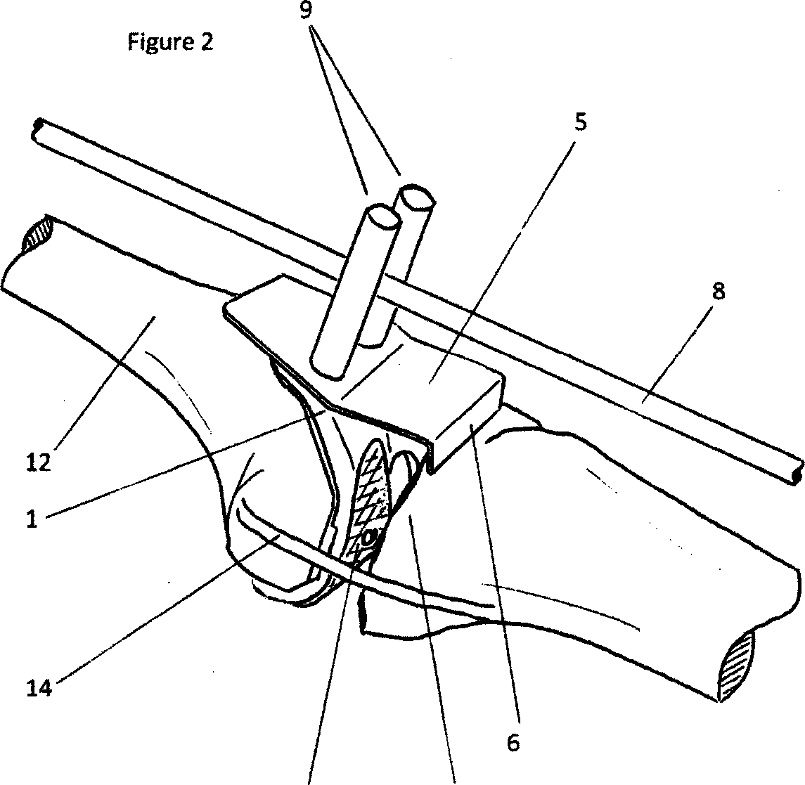
Figure 2. Left lower limb under traction. Modified femoral trial component, extension arm, alignment rod and alignment rod locating bars are illustrated
Figure 3. Further view of the left lower limb under traction. The alignment rod central section is seen: the alignment rod extends in the coronal view from the centre of the ankle joint to the centre of the femoral head. Tibial cutting block now in place on the extension arm, limb aligned, ready to pin tibial cutting block in place
Figure 4. Long alignment rod at its distal end, illustrating a method for attaching it to an ankle traction halter, with the distal end centred over the centre of the ankle joint in the coronal view
Modified femoral trial component, closely follows the distal femoral cut and femoral finishing cuts in a similar fashion to a standard femoral trial component. Of a range of sizes to match the dimensions of the range of femoral components
Distal extent of modified femoral trial component, does not extend distally as far as the usual femoral trial component, so does not reach the joint line
Holes to allow the modified femoral trial component to be removably attached to the distal femur, by threaded screws for example
Locating surface for the extension arm, on the modified femoral trial component with suitable attachment method such as threaded bolt holes
Extension arm removably attached to the modified femoral trial component, the distal extent of this arm indicates the level and orientation of the tibial cut which will result. The extension arm can be of a selection of lengths, incrementally raising or lowering the level of the tibial plateau cut
Distal extent of the extension arm, indicates the level and spatial orientation of the tibial plateau cut, can be removably attached to the tibial cutting block, for example by mating with the saw slot
Tibial cutting block removably attaches to the extension arm, and can be attached to the tibial plateau, for example by smooth or threaded pins placed through the holes visible on the front face of the block
Alignment rod of a range of lengths, to reach from the ankle to the hip joint for each patient
Alignment rod locating lugs, orientated over the anterior aspect of the modified femoral trial component such that the alignment rod passes over the centre line of the component when viewed in the coronal plane. These lugs may perform a secondary purpose, to attach the extension arm onto the modified femoral trial component by way of threaded bolts
Traction halter outer strap, inner foam
Alignment rod attachment, such as a nylon sling, allowing the distal end of the alignment rod to be positioned over the centre of the talus, or the centre of the ankle joint, when viewed in the coronal plane
Distal femur
Tibial plateau
Schematic illustration of collateral ligaments. All other soft tissues are omitted for clarity (excepting Figure 4)
Point for application of Traction
This example of the invention is now described by following through the process in which it can be employed: knee replacement surgery. The description focuses on coronal-plane alignment, and especially on particular aspects pertaining to the positioning of the tibial cutting block.
After exposure of the knee joint, the distal femur 12 is prepared by performing the distal femoral cut and the femoral finishing cuts, using any of the standard techniques, such as measured resection cutting blocks, patient-specific instrumentation, or computer-guided surgery. Peripheral osteophytes are removed from the tibial plateau 13, and any residual osteophytes from the distal femur 12. Of note, there is no requirement for the distal femoral cut to be perpendicular to the mechanical axis. The surgeon may plan the slope (lateral 'high' to medial 'low') of the distal femoral cut to match the slope of the native joint, and the aim of this invention is to allow the surgeon to accurately transpose the slope of the distal femoral cut across to the tibial cut, with the limb aligned.
See Figure 1. The modified femoral trial component 1 is positioned on the distal femur 12, and attached by screws via holes 3. This modified femoral trial component 1 has novel and inventive differences from a standard femoral trial component: firstly, its distal extent does not reach the joint line, allowing the limb to be aligned by traction without impingement between the modified femoral trial component 1 and the tibial plateau 13; secondly it has a locating surface 4 for an extension arm 5, allowing the extension arm 5, and alignment rod locating lugs 9 to be removably attached; thirdly, the screw holes 3 which allow it to be firmly and removably attached to the prepared distal femur 12.
See Figure 4. The limb is aligned by traction applied to the ankle traction halter 10. See Figure 2. The surgeon must check that there is no impingement between the modified femoral trial component 1 and the tibial plateau 13. Impingement will interfere with the ability of ligamentous traction to align the limb. If there is bony impingement, then bone can be excised until no impingement exists. An extension arm 5 is selected from a range of incremental lengths that correspond to the available thickness range of tibial inserts, and attached to the locating surface for the extension arm 4, on the modified femoral trial component 1. The distal extent of the extension arm 6 now indicates the level and spatial orientation of the tibial cut that will result: if too much or too little tibial bone resection is indicated, then a different extension arm 5 can be selected from the range described above. In this specific example, the alignment rod locating lugs 9 have a subsidiary purpose in that they act as threaded bolts attaching the extension arm 5 to the locating surface 4 on the modified femoral trial component 1.
Now, it can be seen that the distal femur 12 has been prepared, and the limb has been aligned by ligamentous traction. The distal extent of the extension arm 6 indicates the spatial plane of the tibial cut that will result. This tibial cut orientation has been referenced from the already-prepared distal femur 12 with the limb aligned. The tibial cut has not been directly referenced from the tibia mechanical axis. Therefore, any error in varus-valgus orientation of the distal femoral cut has been transposed across as an equal and compensatory adjustment in the varus-valgus orientation of the tibial cut.
See Figure 2. The distal extent of the extension arm 6 indicates the spatial plane of the tibial cut. With the limb aligned by ligamentous traction, this plane can be assessed relative to the slope of the native tibial plateau 13. This is commonly known as the 'posterior slope'of the tibial cut, and has important effects on the stability of the knee replacement. The extension arm 5 can be made available with an incremental range of values of posterior slope of its distal extent 6 which can be compared to the slope of the native tibial plateau 13, and the most appropriate value selected.
See Figure 4. The alignment rod 8 is attached distally to the traction halter 10, over the centre of the ankle. See Figures 2 and 3. The alignment rod 8 is located between the alignment rod locating lugs 9 which are positioned such that the alignment rod 8 passes over the centre line of the modified femoral trial component 1 when viewed in the coronal plane. The surgeon now assesses the proximal end of the alignment rod 8 where it lies over the hip joint. If it lies directly over the femoral head centre (as for example can be ascertained with an image intensifier) then the lower limb mechanical axis is neutral: the hip centre, prosthetic knee joint centre, and ankle centre, all lie on the coronal plane mechanical axis.
The surgeon can choose to alter the lower limb alignment that traction has created. This can be achieved by soft tissue releases at the knee. It can also be achieved by moving the proximal end of the alignment rod 8 to a desired position: for example, many surgeons aim to introduce a small amount of overall varus into the lower limb, and this can be achieved by placing the proximal end of the alignment rod 8 over the femoral neck rather than the femoral head. The centre part of the alignment rod 8 will act on the knee's coronal alignment via pressure on the alignment rod locating lugs 9, setting the alignment to the surgeon's satisfaction.
See Figure 3. The traction is temporarily released, and the knee flexed sufficiently to slip the tibial cutting block 7 over the distal extent of the extension arm 6. In this specific example, the distal extent of the extension arm 6 mates closely with the saw slot in the cutting block
7. Traction is re-applied, and alignment checked for a final time. Now, the cutting block 7 is attached to the tibial plateau 13 using smooth or threaded pins, via the drillholes visible on the anterior surface of the tibial cutting block 7. The alignment rod 8 is removed. The extension arm 5 is now removed by detaching the alignment rod locating lugs 9, and slipping the distal extent of the extension arm 6 free from the saw slot of the tibial cutting block 7. The knee can now be flexed in the usual manner, reducing tension in the posterior soft tissue structures and allowing the tibial cut to be made.
Claims (12)
1. An apparatus for setting the alignment of the tibial cut during total knee replacement with reference to the already-prepared femur, comprising of:
a component closely fitting the prepared distal femur in the manner of a femoral trial component that fits closely around the distal femoral cut and femoral finishing cuts; and an extension arm removably attaching to this component that indicates the level and orientation of the tibial cut that will result when the limb is aligned.
2. An apparatus for setting and checking the alignment of a limb prior to the tibial cut during knee replacement surgery, comprising of:
an ankle halter allowing the application of traction with a point of attachment for an alignment rod over the centre of the ankle and extending proximally to the hip joint; and means of removably locating the alignment rod over the centre of the femoral component described in Claim 1, such as parallel alignment lugs or bars.
3. An apparatus as claimed in Claim 1, where the component closely fitting the prepared distal femur is of sufficiently small dimension so as to not extend distally to the level of the joint that would be reached by a standard femoral component closely fitting these similar bone cuts, and so reducing the likelihood of impingement against the tibial plateau.
4. An apparatus as claimed in Claim 1, where a tibial cutting block can be removably attached to the extension arm in such a way that the resulting cut is indicated by the orientation of the distal extent of the extension arm.
5. An apparatus as claimed in Claims 1 and 4, where the tibial cutting block can be attached to the tibial plateau, for example by smooth or threaded pins.
6. An apparatus as claimed in Claims 1,4 and 5, where the extension arm can be unattached from the component closely fitting the prepared distal femur, and unattached from the tibial cutting block, leaving the tibial cutting block in place on the tibial plateau.
7. An apparatus as claimed in Claim 1, where the extension arm can be of a range of lengths which correspond to a range of tibial component thicknesses.
8. An apparatus as claimed in Claim 1, where the distal part of the extension arm that indicates the level and orientation of the tibial cut is of a range of value of slope, corresponding to a range of value of posterior slope of the tibial cut that will result when the limb is aligned.
9. An apparatus as claimed in Claim 1, where the component closely fitting the prepared distal femur has locating holes so that it may be removably attached to the distal femur with screws or other suitable means.
10. An apparatus as claimed in Claim 1, where the component closely fitting the prepared distal femur has an attachment surface for the extension arm, such that the extension arm may be removably attached using screws, bolts or other suitable means.
11. An apparatus as claimed in Claim 1 and Claim 2, where the component closely fitting the prepared distal femur has lugs removably attached to its anterior surface, or to the extension arm, or both, that locate the alignment rod over the centre of the component closely fitting the prepared distal femur when viewed in the coronal plane.
12. An apparatus substantially as described in the text and accompanying drawings.
ytAjg/ZW-1
Intellectual
Property
Office
Application No: GB1620706.0 Examiner: Paul Jenkins
Priority Applications (2)
| Application Number | Priority Date | Filing Date | Title |
|---|---|---|---|
| GB1620706.0A GB2558543A (en) | 2016-12-05 | 2016-12-05 | Apparatus for alignment of knee arthroplasty tibial cutting block |
| PCT/GB2017/053566 WO2018104704A1 (en) | 2016-12-05 | 2017-11-28 | Apparatus for alignment of knee arthroplasty tibial cutting block |
Applications Claiming Priority (1)
| Application Number | Priority Date | Filing Date | Title |
|---|---|---|---|
| GB1620706.0A GB2558543A (en) | 2016-12-05 | 2016-12-05 | Apparatus for alignment of knee arthroplasty tibial cutting block |
Publications (2)
| Publication Number | Publication Date |
|---|---|
| GB201620706D0 GB201620706D0 (en) | 2017-01-18 |
| GB2558543A true GB2558543A (en) | 2018-07-18 |
Family
ID=58159756
Family Applications (1)
| Application Number | Title | Priority Date | Filing Date |
|---|---|---|---|
| GB1620706.0A Withdrawn GB2558543A (en) | 2016-12-05 | 2016-12-05 | Apparatus for alignment of knee arthroplasty tibial cutting block |
Country Status (2)
| Country | Link |
|---|---|
| GB (1) | GB2558543A (en) |
| WO (1) | WO2018104704A1 (en) |
Cited By (1)
| Publication number | Priority date | Publication date | Assignee | Title |
|---|---|---|---|---|
| DE102022207578A1 (en) | 2022-07-25 | 2024-01-25 | Aesculap Ag | Surgical instrument |
Families Citing this family (4)
| Publication number | Priority date | Publication date | Assignee | Title |
|---|---|---|---|---|
| EP4236852A1 (en) | 2020-10-30 | 2023-09-06 | MAKO Surgical Corp. | Robotic surgical system with cut selection logic |
| US12527632B2 (en) | 2020-12-15 | 2026-01-20 | Mako Surgical Corp. | Systems and methods for initial assessment warnings |
| USD1044829S1 (en) | 2021-07-29 | 2024-10-01 | Mako Surgical Corp. | Display screen or portion thereof with graphical user interface |
| WO2024051571A1 (en) * | 2022-09-06 | 2024-03-14 | 北京和华瑞博医疗科技有限公司 | Connecting apparatus, joint surgical apparatus and surgical operation system |
Citations (3)
| Publication number | Priority date | Publication date | Assignee | Title |
|---|---|---|---|---|
| US20100305575A1 (en) * | 2009-05-29 | 2010-12-02 | Zachary Christopher Wilkinson | Methods and Apparatus for Performing Knee Arthroplasty |
| WO2016170306A1 (en) * | 2015-04-20 | 2016-10-27 | Oxford University Innovation Limited | Arthroplasty apparatus and method |
| WO2017223353A1 (en) * | 2016-06-22 | 2017-12-28 | Marlowe Goble E | Knee instruments and methods |
Family Cites Families (4)
| Publication number | Priority date | Publication date | Assignee | Title |
|---|---|---|---|---|
| FR2742037B1 (en) * | 1995-12-07 | 1999-02-19 | Broutard Jean Claude | DEVICE FOR THE PREPARATION OF BONE CUTS, PARTICULARLY TIBIAL FOR THE APPLICATION OF A KNEE PROSTHESIS |
| US7094241B2 (en) | 2002-11-27 | 2006-08-22 | Zimmer Technology, Inc. | Method and apparatus for achieving correct limb alignment in unicondylar knee arthroplasty |
| US7780671B2 (en) * | 2006-01-23 | 2010-08-24 | Zimmer Technology, Inc. | Bone resection apparatus and method for knee surgery |
| US8974459B1 (en) * | 2010-05-21 | 2015-03-10 | Howmedica Osteonics Corp. | Natural alignment knee instruments |
-
2016
- 2016-12-05 GB GB1620706.0A patent/GB2558543A/en not_active Withdrawn
-
2017
- 2017-11-28 WO PCT/GB2017/053566 patent/WO2018104704A1/en not_active Ceased
Patent Citations (3)
| Publication number | Priority date | Publication date | Assignee | Title |
|---|---|---|---|---|
| US20100305575A1 (en) * | 2009-05-29 | 2010-12-02 | Zachary Christopher Wilkinson | Methods and Apparatus for Performing Knee Arthroplasty |
| WO2016170306A1 (en) * | 2015-04-20 | 2016-10-27 | Oxford University Innovation Limited | Arthroplasty apparatus and method |
| WO2017223353A1 (en) * | 2016-06-22 | 2017-12-28 | Marlowe Goble E | Knee instruments and methods |
Cited By (3)
| Publication number | Priority date | Publication date | Assignee | Title |
|---|---|---|---|---|
| DE102022207578A1 (en) | 2022-07-25 | 2024-01-25 | Aesculap Ag | Surgical instrument |
| EP4311507A1 (en) | 2022-07-25 | 2024-01-31 | Aesculap AG | Surgical instrument |
| US12383281B2 (en) | 2022-07-25 | 2025-08-12 | Aesculap Ag | Surgical instrument |
Also Published As
| Publication number | Publication date |
|---|---|
| GB201620706D0 (en) | 2017-01-18 |
| WO2018104704A1 (en) | 2018-06-14 |
Similar Documents
| Publication | Publication Date | Title |
|---|---|---|
| US7842039B2 (en) | Method and apparatus for achieving correct limb alignment in unicondylar knee arthroplasty | |
| US6575980B1 (en) | Method and apparatus for femoral resection | |
| US6558391B2 (en) | Methods and tools for femoral resection in primary knee surgery | |
| US4646729A (en) | Prosthetic knee implantation | |
| US10912658B2 (en) | Arthroplasty apparatus and method | |
| US12161346B2 (en) | Knee resection and gap balancing instruments and techniques for kinematic alignment | |
| US10631885B2 (en) | Patient-matched total knee arthroscopy | |
| US20130211411A1 (en) | Tool For Use In Knee Surgery | |
| US20250152371A1 (en) | Hinge Knee Preparation Instrumentation And Associated Methods | |
| WO2018104704A1 (en) | Apparatus for alignment of knee arthroplasty tibial cutting block | |
| US9005208B2 (en) | Ligament balancing femoral trial | |
| EP3784150A1 (en) | Cutting and drilling template for unicondylar knee arthroplasty | |
| Cooke et al. | Universal bone cutting device for precision knee replacement arthroplasty and osteotomy | |
| Malavolta et al. | Calipered kinematically aligned medial unicompartmental knee arthroplasty: a surgical technique | |
| US20240099858A1 (en) | Gap balancing assembly for knee revision surgery | |
| Hernández-Hermoso | Total knee arthroplasty in extra-articular deformities | |
| Hibono et al. | Total Knee Arthroplasty in Patients with Distal Femoral Malunion: A Case Report | |
| Tria Jr | Instrumentation in total knee arthroplasty | |
| Chaiyakit et al. | Comparative study between the pinless navigation and the articular surface mounted (ASM) navigation in total knee arthroplasty: Radiographic results and early clinical outcomes | |
| Alan et al. | Quadriceps sparing total knee arthroplasty in association with electromagnetic navigation | |
| Shah et al. | Total Knee Arthroplasty in Post High Tibial Osteotomy | |
| Bolognesi | Navigated Total Knee Arthroplasty and the ORTHOsoft Navitrack System | |
| HK1222108A1 (en) | Total knee arthroplasty methods, systems, and instruments |
Legal Events
| Date | Code | Title | Description |
|---|---|---|---|
| WAP | Application withdrawn, taken to be withdrawn or refused ** after publication under section 16(1) |