KR101779920B1 - Tibial resection guide combination assembly - Google Patents
Tibial resection guide combination assembly Download PDFInfo
- Publication number
- KR101779920B1 KR101779920B1 KR1020160037971A KR20160037971A KR101779920B1 KR 101779920 B1 KR101779920 B1 KR 101779920B1 KR 1020160037971 A KR1020160037971 A KR 1020160037971A KR 20160037971 A KR20160037971 A KR 20160037971A KR 101779920 B1 KR101779920 B1 KR 101779920B1
- Authority
- KR
- South Korea
- Prior art keywords
- groove
- cutting guide
- handle
- adapter
- pin
- Prior art date
- Legal status (The legal status is an assumption and is not a legal conclusion. Google has not performed a legal analysis and makes no representation as to the accuracy of the status listed.)
- Expired - Fee Related
Links
Images


Classifications
-
- A—HUMAN NECESSITIES
- A61—MEDICAL OR VETERINARY SCIENCE; HYGIENE
- A61B—DIAGNOSIS; SURGERY; IDENTIFICATION
- A61B17/00—Surgical instruments, devices or methods
- A61B17/16—Instruments for performing osteoclasis; Drills or chisels for bones; Trepans
- A61B17/17—Guides or aligning means for drills, mills, pins or wires
- A61B17/1739—Guides or aligning means for drills, mills, pins or wires specially adapted for particular parts of the body
- A61B17/1764—Guides or aligning means for drills, mills, pins or wires specially adapted for particular parts of the body for the knee
-
- A—HUMAN NECESSITIES
- A61—MEDICAL OR VETERINARY SCIENCE; HYGIENE
- A61B—DIAGNOSIS; SURGERY; IDENTIFICATION
- A61B17/00—Surgical instruments, devices or methods
- A61B17/14—Surgical saws
- A61B17/15—Guides therefor
- A61B17/154—Guides therefor for preparing bone for knee prosthesis
- A61B17/157—Cutting tibia
-
- A—HUMAN NECESSITIES
- A61—MEDICAL OR VETERINARY SCIENCE; HYGIENE
- A61B—DIAGNOSIS; SURGERY; IDENTIFICATION
- A61B17/00—Surgical instruments, devices or methods
- A61B17/16—Instruments for performing osteoclasis; Drills or chisels for bones; Trepans
- A61B17/1662—Instruments for performing osteoclasis; Drills or chisels for bones; Trepans for particular parts of the body
- A61B17/1675—Instruments for performing osteoclasis; Drills or chisels for bones; Trepans for particular parts of the body for the knee
-
- A—HUMAN NECESSITIES
- A61—MEDICAL OR VETERINARY SCIENCE; HYGIENE
- A61F—FILTERS IMPLANTABLE INTO BLOOD VESSELS; PROSTHESES; DEVICES PROVIDING PATENCY TO, OR PREVENTING COLLAPSING OF, TUBULAR STRUCTURES OF THE BODY, e.g. STENTS; ORTHOPAEDIC, NURSING OR CONTRACEPTIVE DEVICES; FOMENTATION; TREATMENT OR PROTECTION OF EYES OR EARS; BANDAGES, DRESSINGS OR ABSORBENT PADS; FIRST-AID KITS
- A61F2/00—Filters implantable into blood vessels; Prostheses, i.e. artificial substitutes or replacements for parts of the body; Appliances for connecting them with the body; Devices providing patency to, or preventing collapsing of, tubular structures of the body, e.g. stents
- A61F2/02—Prostheses implantable into the body
- A61F2/30—Joints
- A61F2/38—Joints for elbows or knees
- A61F2/3836—Special connection between upper and lower leg, e.g. constrained
-
- A—HUMAN NECESSITIES
- A61—MEDICAL OR VETERINARY SCIENCE; HYGIENE
- A61F—FILTERS IMPLANTABLE INTO BLOOD VESSELS; PROSTHESES; DEVICES PROVIDING PATENCY TO, OR PREVENTING COLLAPSING OF, TUBULAR STRUCTURES OF THE BODY, e.g. STENTS; ORTHOPAEDIC, NURSING OR CONTRACEPTIVE DEVICES; FOMENTATION; TREATMENT OR PROTECTION OF EYES OR EARS; BANDAGES, DRESSINGS OR ABSORBENT PADS; FIRST-AID KITS
- A61F2/00—Filters implantable into blood vessels; Prostheses, i.e. artificial substitutes or replacements for parts of the body; Appliances for connecting them with the body; Devices providing patency to, or preventing collapsing of, tubular structures of the body, e.g. stents
- A61F2/02—Prostheses implantable into the body
- A61F2/30—Joints
- A61F2/38—Joints for elbows or knees
- A61F2/389—Tibial components
-
- A—HUMAN NECESSITIES
- A61—MEDICAL OR VETERINARY SCIENCE; HYGIENE
- A61F—FILTERS IMPLANTABLE INTO BLOOD VESSELS; PROSTHESES; DEVICES PROVIDING PATENCY TO, OR PREVENTING COLLAPSING OF, TUBULAR STRUCTURES OF THE BODY, e.g. STENTS; ORTHOPAEDIC, NURSING OR CONTRACEPTIVE DEVICES; FOMENTATION; TREATMENT OR PROTECTION OF EYES OR EARS; BANDAGES, DRESSINGS OR ABSORBENT PADS; FIRST-AID KITS
- A61F2/00—Filters implantable into blood vessels; Prostheses, i.e. artificial substitutes or replacements for parts of the body; Appliances for connecting them with the body; Devices providing patency to, or preventing collapsing of, tubular structures of the body, e.g. stents
- A61F2/02—Prostheses implantable into the body
- A61F2/30—Joints
- A61F2/46—Special tools for implanting artificial joints
- A61F2/4684—Trial or dummy prostheses
-
- A—HUMAN NECESSITIES
- A61—MEDICAL OR VETERINARY SCIENCE; HYGIENE
- A61B—DIAGNOSIS; SURGERY; IDENTIFICATION
- A61B17/00—Surgical instruments, devices or methods
- A61B2017/00477—Coupling
Landscapes
- Health & Medical Sciences (AREA)
- Life Sciences & Earth Sciences (AREA)
- Orthopedic Medicine & Surgery (AREA)
- Surgery (AREA)
- Oral & Maxillofacial Surgery (AREA)
- Public Health (AREA)
- Engineering & Computer Science (AREA)
- Biomedical Technology (AREA)
- Heart & Thoracic Surgery (AREA)
- Veterinary Medicine (AREA)
- Animal Behavior & Ethology (AREA)
- General Health & Medical Sciences (AREA)
- Transplantation (AREA)
- Physical Education & Sports Medicine (AREA)
- Dentistry (AREA)
- Nuclear Medicine, Radiotherapy & Molecular Imaging (AREA)
- Medical Informatics (AREA)
- Molecular Biology (AREA)
- Vascular Medicine (AREA)
- Cardiology (AREA)
- Surgical Instruments (AREA)
- Prostheses (AREA)
Abstract
본 발명은 일측이 정렬부재와 슬라이드 결합되고 타측이 경골절삭가이드의 어댑터결합홈과 슬라이드 결합되는 정렬결합부와, 상기 정렬결합부에 슬라이딩 가능하게 결합되는 핸들을 포함하는 가이드어댑터를 포함하는 경골절삭가이드 결합 어셈블리에 관한 것으로, 더욱 상세하게는 상기 핸들을 상기 절삭가이드 측으로 슬라이딩시 상기 절삭가이드에 핸들이 고정되어 상기 절삭가이드와 어댑터가 잠금 상태가 되고 상기 핸들을 절삭가이드로부터 반대 방향으로 슬라이딩시 상기 절삭가이드로부터 핸들이 해제되어 상기 절삭기구와 어댑터가 풀림 상태가 되어, 별다른 조작 없이 상기 어댑터를 통한 정렬기구와 절삭가이드의 용이한 결한 및 해제가 가능한 것을 특징으로 하는 경골절삭가이드 결합 어셈블리에 관한 것이다.The present invention relates to a tibial cutting method comprising a tibial cutting operation including a guide adapter including an aligning engaging portion having one side slidably engaged with an aligning member and the other side slidingly engaged with an adapter engaging groove of a tibial cutting guide and a handle slidably engaged with the aligning engaging portion And more particularly, to a guide coupling assembly, more specifically, when the handle is slid to the cutting guide side, the handle is fixed to the cutting guide so that the cutting guide and the adapter are locked and when the handle is slid in the opposite direction from the cutting guide, And the cutting mechanism and the adapter are released from the cutting guide so that the aligning mechanism and the cutting guide can be easily connected and disconnected through the adapter without any operation. .
Description
본 발명은 일측이 정렬부재와 슬라이드 결합되고 타측이 경골절삭가이드의 어댑터결합홈과 슬라이드 결합되는 정렬결합부와, 상기 정렬결합부에 슬라이딩 가능하게 결합되는 핸들을 포함하는 가이드어댑터를 포함하는 경골절삭가이드 결합 어셈블리에 관한 것으로, 더욱 상세하게는 상기 핸들을 상기 절삭가이드 측으로 슬라이딩시 상기 절삭가이드에 핸들이 고정되어 상기 절삭가이드와 어댑터가 잠금 상태가 되고 상기 핸들을 절삭가이드로부터 반대 방향으로 슬라이딩시 상기 절삭가이드로부터 핸들이 해제되어 상기 절삭기구와 어댑터가 풀림 상태가 되어, 별다른 조작 없이 상기 어댑터를 통한 정렬기구와 절삭가이드의 용이한 결한 및 해제가 가능한 것을 특징으로 하는 경골절삭가이드 결합 어셈블리에 관한 것이다.The present invention relates to a tibial cutting method comprising a tibial cutting operation including a guide adapter including an aligning engaging portion having one side slidably engaged with an aligning member and the other side slidingly engaged with an adapter engaging groove of a tibial cutting guide and a handle slidably engaged with the aligning engaging portion And more particularly, to a guide coupling assembly, more specifically, when the handle is slid to the cutting guide side, the handle is fixed to the cutting guide so that the cutting guide and the adapter are locked and when the handle is slid in the opposite direction from the cutting guide, And the cutting mechanism and the adapter are released from the cutting guide so that the aligning mechanism and the cutting guide can be easily connected and disconnected through the adapter without any operation. .
관절염, 외상 등에 의해 무릎관절이 제기능을 상실하였을 때 파괴된 관절을 대치할 수 있는 임플란트를 이식하여 정상적인 무릎관절의 기능을 수행할 수 있도록 인공관절 치환술을 시술하게 된다.When knee joints lose their function due to arthritis or trauma, implants that can replace the fractured joints are implanted to perform artificial joint replacement to perform normal knee joint function.
도 1 내지 도3은 슬관절에 대한 인공관절 치환술을 설명하기 위한 참고도이고, 도 4는 종래의 경골절삭가이드 결합 어셈블리를 설명하기 위한 참고도이다. FIGS. 1 to 3 are reference views for explaining artificial joint replacement for a knee joint, and FIG. 4 is a reference diagram for explaining a conventional tibial cutting guide coupling assembly.
도 1 내지 도 3 참조하여 인공관절 치환술에 대해 구체적으로 살펴보면, 대퇴골(F)에는 대퇴요소(700)가 결합되고 경골(T)에는 경골요소(800)가 결합되며 상기 대퇴요소(700)와 경골요소(800) 사이에는 베어링이 위치한다. 경골(T) 부위에 대해 살펴보면, 상기 경골(T)에는 절단면이 형성되어야 하는데, 상기 절단면을 형성하기 위해 경골절삭가이드(절단 블록)(R)이 사용된다. 상기 경골절삭가이드(R)를 경골(T)에 고정시킨 이후 상기 절삭가이드(R)에 형성되어 있는 슬롯에 절단 블레이드 등을 삽입하여 절단면을 형성하게 된다. 상기 경골(T)에 정확한 절단면을 형성하기 위하여 상기 경골에 정렬기구(A)를 고정시킨다. 상기 정렬기구(A)는 일반적으로 기계축과 일치하도록 상기 경골(T)과 평행하게 고정되며, 그 이후 상기 정렬기구(A)와 경골절삭가이드(R)가 상호 결합하여 상기 절삭가이드(R)가 상기 경골(T)에 정확하게 고정될 수 있도록 한다. 1-3, the
그러나 도 4를 참조하여 종래의 경골절삭가이드(R)와 정렬기구(A)의 결합방식을 살펴보면, 일반적으로 경골절삭가이드(R)의 결합홈(H1)에 정렬기구의 정렬부재(A)가 삽입된다. 그 이후 상기 절삭가이드(R)의 체결수단삽입홈(H2)에 스크류(S) 등의 체결수단을 삽입하고 밀착시켜 상기 정렬부재(A)와 경골절삭가이드(R)를 고정한다. 따라서, 상호 결합시 상기 스크류(S)를 돌려 상기 정렬부재(A)를 압박하여 고정시키며, 상기 절삭가이드(R)가 경골(T)에 정확하게 고정된 이후에는 다시 스크류(S)를 반대방향으로 돌린 이후 상기 정렬기구(A)를 경골절삭가이드(R)로부터 해제시킨다. 따라서, 체결수단의 별도의 조작에 의해 결합 및 해제를 하여야 하므로, 사용이 상대적으로 번거로워 불편함을 초래할 수밖에 없다. 또한, 별도의 조작이 동반되므로 수술시간이 상대적으로 지연되고 그에 따른 환자의 과다출혈 및 후유증 발생 가능성이 높아 질수밖에 없다.4, the conventional tibial cutting guide R and the aligning mechanism A are combined. In general, the aligning member A of the aligning mechanism is provided in the engaging groove H1 of the tibial cutting guide R . Thereafter, a fastening means such as a screw (S) is inserted into the fastening means insertion groove (H2) of the cutting guide (R) and brought into close contact therewith to fix the alignment member (A) and the tibia cutting guide (R). Therefore, the screw S is rotated to fix the aligning member A when the two are mutually coupled. After the cutting guide R is accurately fixed to the tibia T, the screw S is moved in the opposite direction The aligning mechanism A is released from the tibia cutting guide R. [ Therefore, the engaging and disengaging must be performed by a separate operation of the engaging means, so that the use of the engaging means is relatively cumbersome and inconvenient. In addition, since the operation is accompanied by a separate operation, the operation time is relatively delayed and the possibility of excessive bleeding and sequelae of the patient can be increased.
등록특허 제10-0431911호는 경골 절제 장비에 관한 것으로서, 구체적으로 환자의 근접 경골을 준비하기 위한 장치로 장비 본체(22)와, 골수 내 도관을 추적하기 위한 로드(21)와, 환자의 경골의 절개 중에 절개 블레이드를 안내하기 위한 절개 가이드(20)와, 경골에 대한 절개부의 깊이를 설정하기 위한 수단을 포함하는 경골 절제 장비에 관한 것이다.Patent No. 10-0431911 relates to a tibial resection device, and more particularly to a device for preparing a proximal tibia of a patient, comprising a device body 22, a rod 21 for tracing an intramedullary conduit, A cutting guide 20 for guiding the cutting blade during the incision of the tibia, and means for setting the depth of the incision for the tibia.
상기 등록특허는 정렬슬리브(18), 절개가이드(20), 수직포스트(36) 및 비임(51) 등을 상호 결합하는 과정에서 세트 스크류(32, 57) 등의 별도의 체결수단을 사용하여 장비 간 결합 및 해제를 하므로, 그 구성이 지나치게 복잡하고 결합방식 역시 상대적으로 복잡하여 전술한 문제점인 수술시간 지연 및 과다출혈 및 후유증 발생 가능성이 상대적으로 높을 수밖에 없다.In the process of coupling the alignment sleeve 18, the incision guide 20, the vertical post 36, and the
따라서, 경골절삭가이드와 정렬기구가 별도의 조작 없이 단순한 방식으로 결합 및 해제되어 수술시간의 상대적 단축 및 그에 따른 환자의 출혈 및 후유증 발생 가능성을 최소화할 수 있는 결합방식이 요구되고 있는 실정이다.Accordingly, there is a demand for a coupling method that can minimize the possibility of shortening the operation time and the possibility of hemorrhage and sequelae of the patient, by combining and releasing the tibia cutting guide and the alignment mechanism in a simple manner without any special operation.
본 발명은 상기와 같은 문제점을 해결하기 위해 안출된 것으로,SUMMARY OF THE INVENTION The present invention has been made to solve the above problems,
본 발명은 정렬부재에 대해 가동적으로 결합되어 경골절삭가이드를 상기 정렬부재에 용이하게 탈부착시킬 수 있는 가이드어댑터를 통해 별다른 조작 없이 상기 절삭가이드와 가이드어댑터가 결합할 수 있어 수술시간의 단축 및 그에 따른 환자의 출혈 및 후유증 발생의 최소화를 도모할 수 있는 경골절삭가이드 결합 어셈블리를 제공하는데 그 목적이 있다.According to the present invention, the cutting guide and the guide adapter can be engaged with each other through a guide adapter which is movably coupled to the alignment member and can easily attach and detach the tibia cutting guide to the alignment member, The present invention provides a tibial cutting guide coupling assembly capable of minimizing occurrence of hemorrhage and sequelae in a patient.
또한, 본 발명은 핸들이 절삭가이드 측으로 슬라이딩시 상기 절삭가이드에 핸들이 고정되어 상기 절삭가이드와 어댑터가 잠금 상태에 놓이며, 상기 핸들을 절삭가이드로부터 반대 방향으로 슬라이딩시 상기 절삭가이드로부터 핸들이 해제되어 상기 절삭가이드와 어댑터가 풀림 상태에 놓여 상기 어댑터와 절삭가이드의 용이한 결합과 해제를 도모할 수 있는 경골절삭가이드 결합 어셈블리를 제공하는데 그 목적이 있다.According to the present invention, when the handle is slid to the cutting guide side, the handle is fixed to the cutting guide so that the cutting guide and the adapter are locked. When the handle is slid in the opposite direction from the cutting guide, And to provide a tibial cutting guide coupling assembly in which the cutting guide and the adapter are in an unfolded state so that the adapter and the cutting guide can be easily engaged and disengaged.
또한, 본 발명은 핸들을 상기 절삭가이드 측으로 슬라이딩하면 상기 핀이 절삭가이드의 일측에 삽입 수용되어 상기 어댑터와 절삭가이드가 잠금 상태에 놓여 상하 방향으로의 상호 해제가 방지되고, 상기 핸들을 절삭가이드 측으로부터 반대방향으로 슬라이딩하면 상기 핀의 삽입이 해제되어 상기 어댑터와 절삭가이드가 풀림 상태에 놓여 상하 방향으로의 상호 해제가 가능하여 상기 어댑터를 통한 정렬부재와 절삭가이드의 용이한 결합과 해제를 도모할 수 있는 경골절삭가이드 결합 어셈블리를 제공하는데 그 목적이 있다.According to the present invention, when the handle is slid to the cutting guide side, the pin is inserted into one side of the cutting guide and the adapter and the cutting guide are in a locked state to prevent mutual release in the vertical direction, The insertion of the pin is released so that the adapter and the cutting guide are in the released state and mutually released in the vertical direction so that the alignment member and the cutting guide can be easily engaged and disengaged through the adapter The present invention provides a tibial cutting guide coupling assembly for a tibial cutting tool.
또한, 본 발명은 상기 핸들을 상기 절삭가이드 측으로 슬라이딩하면 파지부의 제 1 핀홈에 삽입되어 있는 핀이 상기 절삭가이드의 핀삽입홈에 진입하여 잠금 상태가 되고, 상기 핸들을 절삭가이드 측으로부터 슬라이딩하면 핀삽입홈에 진입한 핀이 해제되어 풀림 상태가 되어 별다른 체결수단 없이 상기 정렬부재와 절삭가이드의 용이한 결합과 해제를 도모할 수 있는 경골절삭가이드 결합 어셈블리를 제공하는데 그 목적이 있다.Further, according to the present invention, when the handle is slid to the cutting guide side, the pin inserted in the first pin groove of the gripping portion enters the pin insertion groove of the cutting guide to be locked, and when the handle is slid from the cutting guide side And it is an object of the present invention to provide a tibial cutting guide guide assembly capable of easily engaging and disengaging the aligning member and the cutting guide without any fastening means since the pin inserted into the pin insertion groove is released and released.
또한, 본 발명은 핸들의 일측에 형성된 슬라이드홈과 정렬결합부의 일측에 형성된 슬라이드부를 통해 상기 핸들과 정렬결합부가 슬라이드 결합할 수 있어 용이한 결합을 도모함과 동시에 상기 핸들과 정렬결합부가 상하 방향으로 해제되는 것을 방지하는 경골절삭가이드 결합 어셈블리를 제공하는데 그 목적이 있다.Further, according to the present invention, the handle and the aligning and engaging part can be slidably coupled through the slide groove formed at one side of the handle and the slide part formed at one side of the aligning and engaging part, The present invention provides a tibial cutting guide coupling assembly for preventing a tibia cutting guide from being tilted.
또한, 본 발명은 결합홈삽입부가 상기 경골절삭가이드의 어댑터결합홈에 수용되어 상기 어댑터가 절삭가이드로부터 전후 방향으로 해제되는 것을 방지할 수 있는 경골절삭가이드 결합 어셈블리를 제공하는데 그 목적이 있다.It is also an object of the present invention to provide a tibial cutting guide coupling assembly capable of preventing the adapter from being released from the cutting guide in the forward and backward directions, by being received in the adapter coupling groove of the tibia cutting guide.
또한, 본 발명은 상기 핸들과 정렬결합부의 슬라이드 결합시 각각의 파지부가 상기 양 파지부 내측에 위치한 양 부재결합부를 압박하여 상기 부재결합부의 상기 정렬부재에 대한 슬라이드 이동을 제한하여 상기 정렬부재와 어댑터의 견고한 결합을 가능하게 하는 경골절삭가이드 결합 어셈블리를 제공하는데 그 목적이 있다.In addition, according to the present invention, when the handle and the aligning and engaging portion are slidably engaged, each gripping portion presses the both member engaging portions located inside the both grip portions to restrict the slide movement of the member engaging portion with respect to the aligning member, The present invention is directed to a tibial cutting guide coupling assembly that enables a rigid coupling of a tibial cutting guide guide assembly.
또한, 본 발명은 핸들의 연결부 상부면 일측에 관통 형성되는 제 2 핀홈과 정렬결합부의 결합홈삽입부 상부면 일측에 함입 형성되는 제 3 핀홈을 통해 상기 핸들에 슬라이드 결합된 정렬결합부가 전후 방향으로 해제되는 것을 방지하는 경골절삭가이드 결합 어셈블리를 제공하는데 그 목적이 있다.According to the present invention, the second pin groove is formed at one side of the upper surface of the connection portion of the handle and the third pin groove formed at one side of the upper surface of the coupling groove insertion portion of the alignment coupling portion. Thereby preventing the tibia cutting guide from being disengaged.
또한, 본 발명은 상기 제 3 핀홈을 장방형의 홈으로 형성하여 상기 정렬결합부에 결합된 핸들의 전후 방향으로의 일정 거리 슬라이딩을 허용하여 상기 절삭가이드와 어댑터의 잠금 상태와 풀림 상태를 결정할 수 있는 경골절삭가이드 결합 어셈블리를 제공하는데 그 목적이 있다.Further, the third pin groove may be formed as a rectangular groove to permit sliding of the handle coupled to the aligning and engaging portion by a predetermined distance in the forward and backward directions, thereby determining the locked state and the released state of the cutting guide and the adapter And an object of the present invention is to provide a tibial cutting guide coupling assembly.
또한, 본 발명은 결합홈삽입부의 상부면에 일정 깊이 함입 형성되어 내부에 볼플런저를 수용하는 볼홈과, 연결부의 슬라이드홈 상부면 일측에 일정 깊이 함입 형성되어 볼홈에 수용되어 있는 볼플런저의 볼을 통해 상기 가이드어댑터의 잠금 상태와 풀림 상태를 가이드 하는 볼수용홈을 통해 사용의 안정성을 도모할 수 있는 경골절삭가이드 결합 어셈블리를 제공하는데 그 목적이 있다.According to another aspect of the present invention, there is provided an apparatus for inserting a ball plunger, the ball plunger having a ball groove for receiving a ball plunger therein, And an object of the present invention is to provide a tibial cutting guide coupling assembly capable of providing stability through use of a ball groove for guiding a locked state and an unlocked state of the guide adapter.
또한, 본 발명은 연결부의 제 1 볼수용홈과 제 2 볼수용홈이 상기 절삭가이드와 어댑터의 잠금 상태와 풀림 상태를 가이드 하여 사용의 안정성을 더욱 도모할 수 있는 경골절삭가이드 결합 어셈블리를 제공하는데 그 목적이 있다.In addition, the present invention provides a tibia cutting guide coupling assembly capable of guiding the locked state and the unclamped state of the cutting guide and the adapter to further improve the stability of use, in which the first and second ball- .
또한, 본 발명은 결합홈삽입부의 일측에 일정 깊이 함입 형성되어 내부에 자석을 수용하는 자석수용홈을 포함하여 상기 절삭가이드와 접촉하는 측의 결합홈삽입부가 자석의 인력에 의해 상기 절삭가이드와 더욱 견고하게 결합할 수 있는 경골절삭가이드 결합 어셈블리를 제공하는데 그 목적이 있다.According to another aspect of the present invention, there is provided a magnetic disk apparatus including a magnet receiving groove formed at one side of an engaging groove inserting portion to receive a magnet therein, the engaging groove inserting portion contacting the cutting guide, The present invention provides a tibia cutting guide coupling assembly that can be firmly coupled.
또한, 본 발명은 결합홈삽입부의 원위면의 양 측면 모서리부에 일정 각도로 경사지게 깎아낸 경사면과, 최하부 모서리부를 곡면으로 깎아낸 곡면부를 통해 상기 정렬결합부가 어댑터결합홈에 삽입될 때 모서리 간의 간섭을 완화하여 상기 절삭가이드와 어댑터의 상호 용이한 결합을 도모할 수 있는 경골절삭가이드 결합 어셈블리를 제공하는데 그 목적이 있다.Further, the present invention is characterized in that, when the alignment engaging portion is inserted into the adapter engaging groove through an inclined face sloped at an angle to both side edge portions of the remote side of the remote groove of the engaging groove inserting portion and a curved face portion cut to the curved face of the lowermost corner portion, And to provide a tibia cutting guide coupling assembly capable of facilitating mutual coupling of the cutting guide and the adapter.
본 발명은 앞서 본 목적을 달성하기 위해서 다음과 같은 구성을 가진 실시예에 의해서 구현된다.In order to achieve the above object, the present invention is implemented by the following embodiments.
본 발명의 일 실시예에 따르면, 본 발명에 따른 경골절삭가이드 결합 어셈블리는 경골절삭가이드를 정렬부재에 거치시키는 가이드어댑터를 포함하며, 상기 가이드어댑터는 상기 정렬부재에 대해 가동적으로 결합되어 상기 경골절삭가이드를 상기 정렬부재에 용이하게 탈부착할 수 있도록 하는 것을 특징으로 한다.According to an embodiment of the present invention, a tibial cutting guide coupling assembly according to the present invention includes a guide adapter for mounting a tibia cutting guide to an alignment member, wherein the guide adapter is operatively engaged with the alignment member, So that the cutting guide can be easily attached to and detached from the alignment member.
본 발명의 다른 실시예에 따르면, 본 발명에 따른 경골절삭가이드 결합 어셈블리의 상기 가이드어댑터는 상기 정렬부재와 절삭가이드에 슬라이딩 가능하게 결합되는 정렬결합부와, 상기 정렬결합부에 슬라이딩 가능하게 결합되는 핸들을 포함하며, 상기 핸들은 상기 정렬결합부에 슬라이딩 되면서 상기 경골절삭가이드와 탈부착 될 수 있는 것을 특징으로 한다.According to another embodiment of the present invention, the guide adapter of the tibia cutting guide coupling assembly according to the present invention includes: an alignment coupling portion slidably coupled to the alignment member and the cutting guide; And the handle is slid to the alignment coupling part and can be detached and attached to the tibia cutting guide.
본 발명의 또 다른 실시예에 따르면, 본 발명에 따른 경골절삭가이드 결합 어셈블리의 상기 핸들이 상기 정렬결합부에 대해 슬라이딩 되는 방향은 상기 정렬결합부가 상기 정렬부재에 슬라이드 결합되는 방향에 대략 직각인 것을 특징으로 한다.According to another embodiment of the present invention, the direction in which the handle of the tibia cutting guide coupling assembly according to the present invention is slid with respect to the alignment engaging portion is substantially perpendicular to the direction in which the aligning engaging portion is slidably engaged with the aligning member .
본 발명의 또 다른 실시예에 따르면, 본 발명에 따른 경골절삭가이드 결합 어셈블리의 상기 핸들이 상기 절삭가이드 측으로 슬라이딩시 상기 절삭가이드에 핸들이 고정되어 상기 절삭가이드와 어댑터가 잠금 상태에 놓이며, 상기 핸들을 절삭가이드로부터 반대 방향으로 슬라이딩시 상기 절삭가이드로부터 핸들이 해제되어 상기 절삭가이드와 어댑터가 풀림 상태에 놓이는 것을 특징으로 한다.According to another embodiment of the present invention, when the handle of the tibia cutting guide coupling assembly according to the present invention is slid to the cutting guide side, the handle is fixed to the cutting guide so that the cutting guide and the adapter are locked, When the handle is slid in the opposite direction from the cutting guide, the handle is released from the cutting guide so that the cutting guide and the adapter are placed in the unfolded state.
본 발명의 또 다른 실시예에 따르면, 본 발명에 따른 경골절삭가이드 결합 어셈블리의 상기 핸들은 내측에 일정 공간이 형성될 수 있도록 한 쌍이 상호 대향하여 형성되며 상기 정렬결합부로부터 슬라이딩 되어 상기 절삭가이드와 탈부착되는 파지부를 포함하고, 상기 파지부는 원위면 일측에 일정 깊이 함입 형성되어 핀을 수용하는 제 1 핀홈을 포함하여 상기 제 1 핀홈과, 상기 절삭가이드의 핀삽입홈의 위치가 정렬된 상태에서 상기 핸들을 절삭가이드 측으로 슬라이딩시 상기 제 1 핀홈의 핀이 상기 핀삽입홈에 진입하여 잠금 상태가 되며, 상기 핸들을 반대 방향으로 슬라이딩시 상기 핀삽입홈으로부터 핀이 해제되어 풀림 상태가 되는 것을 특징으로 한다.According to another embodiment of the present invention, the handle of the tibia cutting guide coupling assembly according to the present invention is formed such that a pair of the handles are formed so as to have a predetermined space therebetween and are slid from the alignment engaging portion, Wherein the gripping portion includes a first pin groove formed at one side of the distal surface to receive the pin so that the first pin groove and the pin insertion groove of the cutting guide are aligned with each other When the handle is slid to the cutting guide side, the pin of the first pin groove enters the pin insertion groove to be locked, and when the handle is slid in the opposite direction, the pin is released from the pin insertion groove, .
본 발명의 또 다른 실시예에 따르면, 본 발명에 따른 경골절삭가이드 결합 어셈블리의 상기 핸들은 상기 양 파지부와 일체로 형성되어 상기 정렬결합부와 슬라이드 결합하는 연결부를 추가로 포함하고, 상기 연결부는 하부면에 'T' 형상으로 일정 길이 관통 형성되어 상기 핸들과 정렬결합부의 슬라이드 결합을 가능하게 하는 슬라이드홈을 포함하고, 상기 정렬결합부는 한 쌍이 상호 대향하여 내측면에 일정한 형상의 홈을 형성하는 부재결합부와, 상기 양 부재결합부와 일체로 형성되어 일측은 상기 핸들과 슬라이드 결합되고 타측은 상기 절삭가이드의 어댑터결합홈에 삽입되어 슬라이드 결합되는 결합홈삽입부를 포함하고, 상기 결합홈삽입부는 양 측면 최상부로부터 'T' 형상으로 하측으로 일정 길이 돌출되는 슬라이드부를 포함하여 상기 핸들과 정렬결합부의 슬라이드 결합을 가능하게 하는 것을 특징으로 한다.According to another embodiment of the present invention, the handle of the tibia cutting guide coupling assembly according to the present invention further includes a connection portion formed integrally with the both grip portions and slidably engaged with the alignment coupling portion, And a slide groove formed on the lower surface to have a predetermined length in a 'T' shape to allow the handle and the aligning engagement portion to slide together, wherein the aligning engagement portions form a groove having a predetermined shape on the inner side surface, And a coupling groove insertion portion formed integrally with the both member coupling portions, one side of which is slidably engaged with the handle and the other side of which is inserted into the adapter coupling groove of the cutting guide to be slidably engaged, And a slide portion protruding downward in a 'T' shape from a top of both side surfaces by a predetermined length, It characterized in that it enables the slide coupling alignment coupling section.
본 발명의 또 다른 실시예에 따르면, 본 발명에 따른 경골절삭가이드 결합 어셈블리의 상기 핸들과 정렬결합부의 슬라이드 결합시 상기 각각의 파지부가 상기 양 파지부의 내측에 위치한 상기 양 부재결합부를 압박하여 상기 부재결합부의 상기 정렬부재에 대한 슬라이드 이동을 제한하여 상기 정렬부재와 어댑터의 견고한 결합을 가능하게 하는 것을 특징으로 한다.According to another embodiment of the present invention, when the handle and the alignment engaging portion of the tibia cutting guide coupling assembly according to the present invention are slidably engaged, the respective grip portions press the both-member engaging portions located inside the both grip portions, So as to restrict sliding movement of the member-engaging portion with respect to the aligning member, thereby enabling a firm engagement of the aligning member and the adapter.
본 발명의 또 다른 실시예에 따르면, 본 발명에 따른 경골절삭가이드 결합 어셈블리의 상기 연결부는 일측에 수직방향으로 관통 형성되어 핀을 수용하는 제 2 핀홈을 추가적으로 포함하고, 상기 결합홈삽입부는 상부면 일측에 일정 깊이 함입 형성되어 핀을 수용하는 제 3 핀홈을 추가적으로 포함하여 상기 제 2 핀홈과 제 3 핀홈에 삽입된 핀을 통해 상기 핸들과 정렬결합부가 슬라이드 되어 해제되는 것을 방지할 수 있는 것을 특징으로 한다.According to another embodiment of the present invention, the connecting portion of the tibia cutting guide coupling assembly according to the present invention further includes a second pin groove formed at one side thereof in a vertical direction to receive the pin, And a third pin groove formed at one side of the first pin groove and receiving the pin to additionally include a third pin groove to prevent the handle and the aligning and engaging portion from being slidably released through the pin inserted in the second pin groove and the third pin groove. do.
본 발명의 또 다른 실시예에 따르면, 본 발명에 따른 경골절삭가이드 결합 어셈블리의 상기 제 3 핀홈은 장방형으로 형성되어 상기 정렬결합부와 슬라이드 결합된 핸들의 전후방향으로의 일정 거리 슬라이딩을 허용하여 상기 절삭가이드와 어댑터의 잠금과 풀림이 가능하게 할 수 있는 것을 특징으로 한다.According to another embodiment of the present invention, the third pin groove of the tibia cutting guide coupling assembly according to the present invention is formed in a rectangular shape, and allows sliding of the handle, which is slidably engaged with the alignment coupling portion, And the cutting guide and the adapter can be locked and unlocked.
본 발명의 또 다른 실시예에 따르면, 본 발명에 따른 경골절삭가이드 결합 어셈블리의 상기 결합홈삽입부는 상부면 타측에 일정 깊이 함입 형성되어 내부에 볼플런저를 수용하는 볼홈을 추가적으로 포함하고, 상기 연결부는 상기 슬라이드홈의 상부면에 일정 깊이 함입 형성되어 상기 볼플런저의 볼을 수용하여 상기 가이드 어댑터의 잠금과 풀림을 가이드 하는 볼수용홈을 추가적으로 포함하는 것을 특징으로 한다.According to another embodiment of the present invention, the coupling groove insertion portion of the tibia cutting guide coupling assembly according to the present invention further includes a ball groove formed at the other side of the upper surface to receive the ball plunger therein, And a ball groove for receiving a ball of the ball plunger and guiding the locking and unlocking of the guide adapter, the ball groove being formed in a predetermined depth on the upper surface of the slide groove.
본 발명의 또 다른 실시예에 따르면, 본 발명에 따른 경골절삭가이드 결합 어셈블리의 상기 볼수용홈은 상기 슬라이드홈의 상부면 일측으로부터 일정 깊이 함입 형성되어 상기 볼을 수용하여 잠금 상태를 가이드 하는 제 1 볼수용홈과, 상기 제 1 볼수용홈으로부터 일정 거리 이격되어 일정 깊이 함입 형성되어 상기 볼을 수용하여 풀림 상태를 가이드 하는 제 2 볼수용홈을 포함하는 것을 특징으로 한다.According to another embodiment of the present invention, the ball-and-socket groove of the tibia cutting guide-engaging assembly according to the present invention is formed into a predetermined depth from one side of the upper surface of the slide groove, And a second ball groove for receiving the ball and guiding the ball in a released state, the ball groove being spaced apart from the first ball groove by a predetermined distance.
본 발명의 또 다른 실시예에 따르면, 본 발명에 따른 경골절삭가이드 결합 어셈블리의 상기 핸들과 정렬결합부의 슬라이드 결합시 상기 제 1 볼수용홈과 제 2 볼수용홈의 중심점이 상기 제 3 핀홈의 장방형 축 상에 위치하여 상기 정렬결합부와 결합한 핸들의 정확한 슬라이딩을 통한 상기 어댑터와 절삭가이드의 탈부착을 가능하게 하는 것을 특징으로 한다.According to another embodiment of the present invention, when the handle of the tibial cutting guide coupling assembly according to the present invention is slidably engaged with the alignment engaging portion, the center points of the first and second ball- So that it is possible to attach and detach the adapter and the cutting guide through accurate sliding of the handle combined with the alignment coupling part.
본 발명의 또 다른 실시예에 따르면, 본 발명에 따른 경골절삭가이드 결합 어셈블리의 상기 결합홈삽입부는 근위면 일측에 함입 형성되어 내부에 자석을 수용하는 자석수용홈을 추가적으로 포함하여 상기 자석의 인력에 의하여 상기 절삭가이드와 가이드어댑터의 견고한 결합을 도모할 수 있는 것을 특징으로 한다.According to another embodiment of the present invention, the coupling groove insertion portion of the tibia cutting guide coupling assembly according to the present invention further includes a magnet receiving groove formed at one side of the proximal surface to receive the magnet therein, So that the cutting guide and the guide adapter can be firmly engaged with each other.
본 발명의 또 다른 실시예에 따르면, 본 발명에 따른 경골절삭가이드 결합 어셈블리의 상기 자석수용홈에 수용되는 자석은 네오디뮴 자석으로 이루어지는 것을 특징으로 한다.According to another embodiment of the present invention, a magnet received in the magnet receiving groove of the tibia cutting guide coupling assembly according to the present invention is characterized in that it is made of a neodymium magnet.
본 발명의 또 다른 실시예에 따르면, 본 발명에 따른 경골절삭가이드 결합 어셈블리의 상기 결합홈삽입부는 원위면의 양 측면 모서리부에 일정 각도로 경사지게 깎아낸 경사면을 추가적으로 포함하여 상기 정렬결합부를 어댑터결합홈에 삽입시 모서리부 간의 간섭을 최소화하여 상호 용이한 결합을 도모할 수 있는 것을 특징으로 한다.According to another embodiment of the present invention, the coupling groove inserting portion of the tibia cutting guide coupling assembly according to the present invention further includes an inclined surface sloped at an angle to both side edge portions of the distal surface, It is possible to minimize the interference between the corner portions when inserting into the groove, thereby facilitating mutual bonding.
본 발명의 또 다른 실시예에 따르면, 본 발명에 따른 경골절삭가이드 결합 어셈블리의 상기 결합홈삽입부는 원위면의 양 측면 모서리부의 최하측 말단을 곡면으로 형성하는 곡면부를 추가적으로 포함하여 상기 정렬결합부를 어댑터결합홈에 삽입시 모서리부 간의 간섭을 최소화하여 상호 용이한 결합을 도모할 수 있는 것을 특징으로 한다.According to another embodiment of the present invention, the coupling groove inserting portion of the tibia cutting guide coupling assembly according to the present invention further includes a curved surface portion that forms a curved surface at the lowermost end of both side edge portions of the distal surface, The interference between the corner portions can be minimized when inserting into the coupling groove, so that mutual easy coupling can be achieved.
본 발명은 앞서 본 실시예와 하기에서 설명할 구성과 결합, 사용관계에 의해 다음과 같은 효과를 얻을 수 있다.The present invention can obtain the following effects according to the above-described embodiment, the constitution described below, the combination and use relationship.
본 발명은 정렬부재에 대해 가동적으로 결합되어 경골절삭가이드를 상기 정렬부재에 용이하게 탈부착시킬 수 있는 가이드어댑터를 통해 별다른 조작 없이 상기 절삭가이드와 가이드어댑터가 결합할 수 있어 수술시간의 단축 및 그에 따른 환자의 출혈 및 후유증 발생의 최소화를 도모할 수 있는 효과가 있다.According to the present invention, the cutting guide and the guide adapter can be engaged with each other through a guide adapter which is movably coupled to the alignment member and can easily attach and detach the tibia cutting guide to the alignment member, It is possible to minimize the occurrence of bleeding and sequelae in the patient.
또한, 본 발명은 핸들이 절삭가이드 측으로 슬라이딩시 상기 절삭가이드에 핸들이 고정되어 상기 절삭가이드와 어댑터가 잠금 상태에 놓이며, 상기 핸들을 절삭가이드로부터 반대 방향으로 슬라이딩시 상기 절삭가이드로부터 핸들이 해제되어 상기 절삭가이드와 어댑터가 풀림 상태에 놓여 상기 어댑터와 절삭가이드의 용이한 결합과 해제를 도모할 수 있는 효과가 있다.According to the present invention, when the handle is slid to the cutting guide side, the handle is fixed to the cutting guide so that the cutting guide and the adapter are locked. When the handle is slid in the opposite direction from the cutting guide, So that the cutting guide and the adapter are in a released state, so that the adapter and the cutting guide can be easily engaged and disengaged.
또한, 본 발명은 핸들을 상기 절삭가이드 측으로 슬라이딩하면 상기 핀이 절삭가이드의 일측에 삽입 수용되어 상기 어댑터와 절삭가이드가 잠금 상태에 놓여 상하 방향으로의 상호 해제가 방지되고, 상기 핸들을 절삭가이드 측으로부터 반대방향으로 슬라이딩하면 상기 핀의 삽입이 해제되어 상기 어댑터와 절삭가이드가 풀림 상태에 놓여 상하 방향으로의 상호 해제가 가능하여 상기 어댑터를 통한 정렬부재와 절삭가이드의 용이한 결합과 해제를 도모할 수 있는 효과가 있다.According to the present invention, when the handle is slid to the cutting guide side, the pin is inserted into one side of the cutting guide and the adapter and the cutting guide are in a locked state to prevent mutual release in the vertical direction, The insertion of the pin is released so that the adapter and the cutting guide are in the released state and mutually released in the vertical direction so that the alignment member and the cutting guide can be easily engaged and disengaged through the adapter There is an effect that can be.
또한, 본 발명은 상기 핸들을 상기 절삭가이드 측으로 슬라이딩하면 파지부의 제 1 핀홈에 삽입되어 있는 핀이 상기 절삭가이드의 핀삽입홈에 진입하여 잠금 상태가 되고, 상기 핸들을 절삭가이드 측으로부터 슬라이딩하면 핀삽입홈에 진입한 핀이 해제되어 풀림 상태가 되어 별다른 체결수단 없이 상기 정렬부재와 절삭가이드의 용이한 결합과 해제를 도모할 수 있는 효과가 있다.Further, according to the present invention, when the handle is slid to the cutting guide side, the pin inserted in the first pin groove of the gripping portion enters the pin insertion groove of the cutting guide to be locked, and when the handle is slid from the cutting guide side The pin inserted into the pin insertion groove is released to be in a loosened state, so that there is an effect that the alignment member and the cutting guide can be easily engaged and disengaged without any fastening means.
또한, 본 발명은 핸들의 일측에 형성된 슬라이드홈과 정렬결합부의 일측에 형성된 슬라이드부를 통해 상기 핸들과 정렬결합부가 슬라이드 결합할 수 있어 용이한 결합을 도모함과 동시에 상기 핸들과 정렬결합부가 상하 방향으로 해제되는 것을 방지하는 효과가 있다.Further, according to the present invention, the handle and the aligning and engaging part can be slidably coupled through the slide groove formed at one side of the handle and the slide part formed at one side of the aligning and engaging part, There is an effect of preventing the occurrence of the problem.
또한, 본 발명은 결합홈삽입부가 상기 경골절삭가이드의 어댑터결합홈에 수용되어 상기 어댑터가 절삭가이드로부터 전후 방향으로 해제되는 것을 방지할 수 있는 효과가 있다.In addition, the present invention has the effect of preventing the adapter from being released from the cutting guide in the forward and backward directions by receiving the coupling groove insertion portion in the adapter coupling groove of the tibia cutting guide.
또한, 본 발명은 상기 핸들과 정렬결합부의 슬라이드 결합시 각각의 파지부가 상기 양 파지부 내측에 위치한 양 부재결합부를 압박하여 상기 부재결합부의 상기 정렬부재에 대한 슬라이드 이동을 제한하여 상기 정렬부재와 어댑터의 견고한 결합을 가능하게 하는 효과가 있다.In addition, according to the present invention, when the handle and the aligning and engaging portion are slidably engaged, each gripping portion presses the both member engaging portions located inside the both grip portions to restrict the slide movement of the member engaging portion with respect to the aligning member, The present invention has the effect of enabling a rigid coupling of the first and second electrodes.
또한, 본 발명은 핸들의 연결부 상부면 일측에 관통 형성되는 제 2 핀홈과 정렬결합부의 결합홈삽입부 상부면 일측에 함입 형성되는 제 3 핀홈을 통해 상기 핸들에 슬라이드 결합된 정렬결합부가 전후 방향으로 해제되는 것을 방지하는 효과가 있다.According to the present invention, the second pin groove is formed at one side of the upper surface of the connection portion of the handle and the third pin groove formed at one side of the upper surface of the coupling groove insertion portion of the alignment coupling portion. There is an effect of preventing release.
또한, 본 발명은 상기 제 3 핀홈을 장방형의 홈으로 형성하여 상기 정렬결합부에 결합된 핸들의 전후 방향으로의 일정 거리 슬라이딩을 허용하여 상기 절삭가이드와 어댑터의 잠금 상태와 풀림 상태를 결정할 수 있는 효과가 있다.Further, the third pin groove may be formed as a rectangular groove to permit sliding of the handle coupled to the aligning and engaging portion by a predetermined distance in the forward and backward directions, thereby determining the locked state and the released state of the cutting guide and the adapter It is effective.
또한, 본 발명은 결합홈삽입부의 상부면에 일정 깊이 함입 형성되어 내부에 볼플런저를 수용하는 볼홈과, 연결부의 슬라이드홈 상부면 일측에 일정 깊이 함입 형성되어 볼홈에 수용되어 있는 볼플런저의 볼을 통해 상기 가이드어댑터의 잠금 상태와 풀림 상태를 가이드 하는 볼수용홈을 통해 사용의 안정성을 도모할 수 있는 효과가 있다.According to another aspect of the present invention, there is provided an apparatus for inserting a ball plunger, the ball plunger having a ball groove for receiving a ball plunger therein, There is an effect that the stability of use can be achieved through the ball groove for guiding the locked state and the unlocked state of the guide adapter through the guide groove.
또한, 본 발명은 연결부의 제 1 볼수용홈과 제 2 볼수용홈이 상기 절삭가이드와 어댑터의 잠금 상태와 풀림 상태를 가이드 하여 사용의 안정성을 더욱 도모할 수 있는 효과가 있다.Further, according to the present invention, the first and second ball-and-socket grooves of the connecting portion guide the locking state and the unlocking state of the cutting guide and the adapter, thereby further improving the stability of use.
또한, 본 발명은 결합홈삽입부의 일측에 일정 깊이 함입 형성되어 내부에 자석을 수용하는 자석수용홈을 포함하여 상기 절삭가이드와 접촉하는 측의 결합홈삽입부가 자석의 인력에 의해 상기 절삭가이드와 더욱 견고하게 결합할 수 있는 효과가 있다.According to another aspect of the present invention, there is provided a magnetic disk apparatus including a magnet receiving groove formed at one side of an engaging groove inserting portion to receive a magnet therein, the engaging groove inserting portion contacting the cutting guide, It has an effect of being firmly coupled.
또한, 본 발명은 결합홈삽입부의 원위면의 양 측면 모서리부에 일정 각도로 경사지게 깎아낸 경사면과, 최하부 모서리부를 곡면으로 깎아낸 곡면부를 통해 상기 정렬결합부가 어댑터결합홈에 삽입될 때 모서리 간의 간섭을 완화하여 상기 절삭가이드와 어댑터의 상호 용이한 결합을 도모할 수 있는 효과가 있다.Further, the present invention is characterized in that, when the alignment engaging portion is inserted into the adapter engaging groove through an inclined face sloped at an angle to both side edge portions of the remote side of the remote groove of the engaging groove inserting portion and a curved face portion cut to the curved face of the lowermost corner portion, The cutting guide and the adapter can be easily combined with each other.
도 1 내지 3은 슬관절에 대한 인공관절 치환술을 설명하기 위한 참고도
도 4는 종래의 경골절삭가이드 결합 어셈블리를 설명하기 위한 참고도
도 5는 본 발명의 일 실시예에 따른 경골절삭가이드 결합 어셈블리의 사시도
도 6은 도 5에 따른 경골절삭가이드 결합 어셈블리의 분해사시도
도 7은 도 5에 따른 정렬기구의 사시도
도 8은 도 5에 따른 경골절삭가이드의 사시도
도 9는 도 5에 따른 가이드어댑터의 사시도
도 10은 도 9에 따른 가이드어댑터의 분해사시도
도 11은 도 9에 따른 핸들의 사시도
도 12는 도 11에 따른 핸들의 저면도
도 13 및 도 14는 도 9에 따른 정렬결합부의 사시도
도 15는 정렬부재, 핸들 및 정렬결합부의 결합과정을 설명하기 위한 참고도
도 16는 제 1 및 제 2 볼수용홈의 중심점이 제 3 핀홈의 장방형 축 상에 위치하는 것을 설명하기 위한 참고도
도 17 및 도 18은 가이드어댑터를 통한 정렬부재와 경골절삭가이드의 결합(부착)과정을 설명하기 위한 참고도
도 19 및 도 20은 경골절삭가이드로부터 정렬부재 및 가이드어댑터의 해제(탈착)과정을 설명하기 위한 참고도Figs. 1 to 3 are views for explaining artificial joint replacement for a knee joint
Fig. 4 is a view for explaining a conventional tibia cutting guide coupling assembly
5 is a perspective view of a tibia cutting guide coupling assembly according to an embodiment of the present invention.
FIG. 6 is an exploded perspective view of the tibia cutting guide coupling assembly according to FIG.
Figure 7 is a perspective view of the alignment mechanism according to Figure 5;
Fig. 8 is a perspective view of the tibia cutting guide according to Fig.
Figure 9 is a perspective view of the guide adapter according to Figure 5;
Fig. 10 is an exploded perspective view of the guide adapter according to Fig.
Figure 11 is a perspective view of the handle according to Figure 9;
12 is a bottom view of the handle according to Fig.
Figs. 13 and 14 are perspective views of the alignment engagement portion according to Fig.
15 is a reference view for explaining a process of coupling the alignment member, the handle,
16 is a reference view for explaining that the center points of the first and second ball grooves are located on the rectangular axis of the third pin groove
Figs. 17 and 18 are views for explaining the process of attaching (attaching) the alignment member and the tibia cutting guide through the guide adapter
19 and 20 are views for explaining the process of releasing (removing) the alignment member and the guide adapter from the tibia cutting guide
이하에서는 본 발명에 따른 경골절삭가이드 결합 어셈블리를 첨부된 도면을 참조하여 상세히 설명한다. 도면들 중 동일한 구성요소들은 가능한 한 어느 곳에서든지 동일한 부호들로 나타내고 있음에 유의해야 한다. 또한 본 발명의 요지를 불필요하게 흐릴 수 있는 공지 기능 및 구성에 대한 상세한 설명은 생략한다. 특별한 정의가 없는 한 본 명세서의 모든 용어는 본 발명이 속하는 기술분야의 통상의 지식을 가진 기술자가 이해하는 당해 용어의 일반적 의미와 동일하고 만약 본 명세서에 사용된 용어의 의미와 충돌하는 경우에는 본 명세서에 사용된 정의에 따른다.Hereinafter, a tibia cutting guide coupling assembly according to the present invention will be described in detail with reference to the accompanying drawings. It is to be noted that the same elements among the drawings are denoted by the same reference numerals whenever possible. In the following description, well-known functions or constructions are not described in detail since they would obscure the invention in unnecessary detail. Unless defined otherwise, all terms used herein have the same meaning as commonly understood by one of ordinary skill in the art to which this invention belongs and, if conflict with the meaning of the terms used herein, It follows the definition used in the specification.
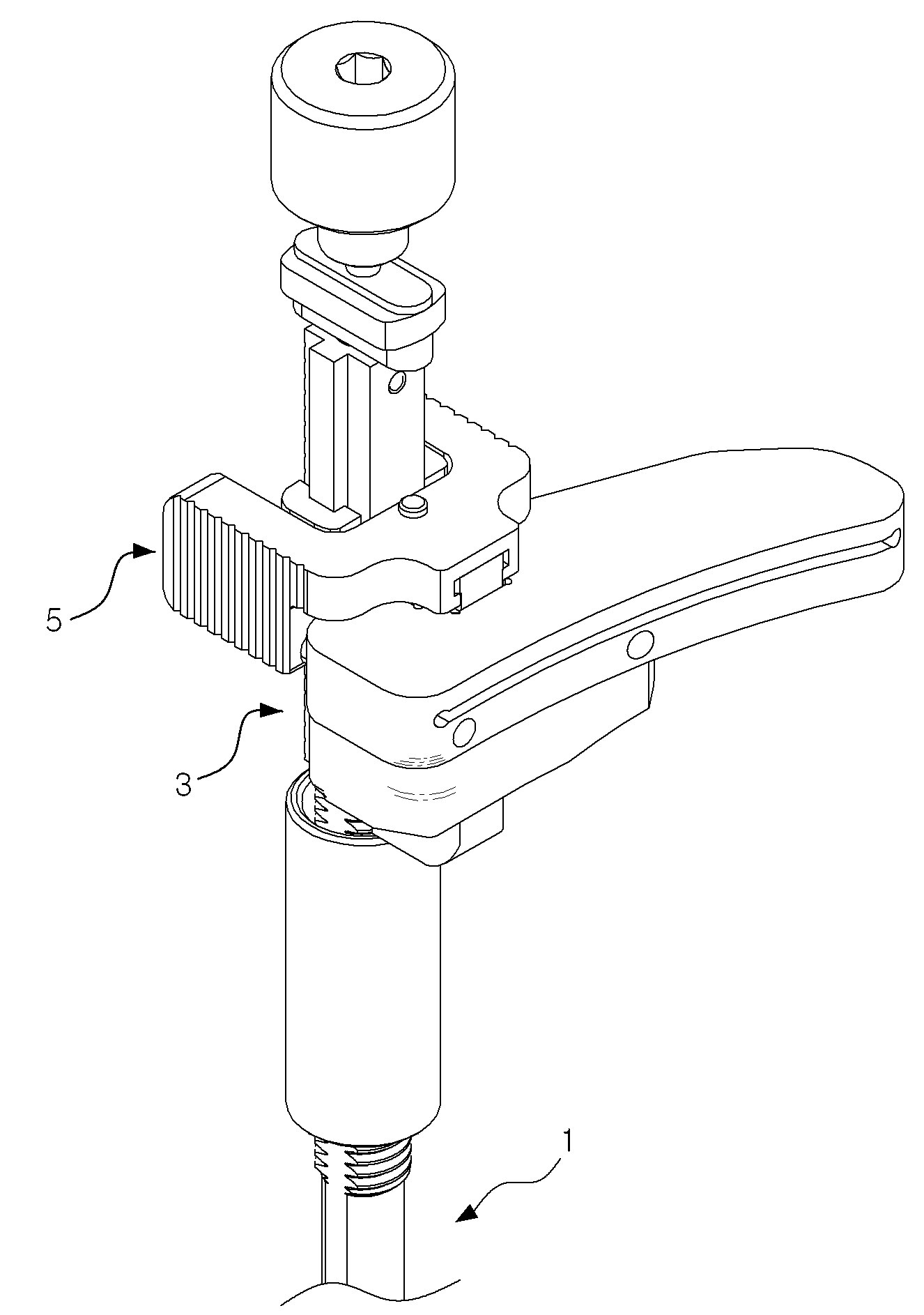
도 5는 본 발명의 일 실시예에 따른 경골절삭가이드 결합 어셈블리의 사시도이고, 도 6은 도 5에 따른 경골절삭가이드 결합 어셈블리의 분해사시도이고, 도 7은 도 5에 따른 정렬기구의 사시도이고, 도 8은 도 5에 따른 경골절삭가이드의 사시도이고, 도 9는 도 5에 따른 가이드어댑터의 사시도이고, 도 10은 도 9에 따른 가이드어댑터의 분해사시도이고, 도 11은 도 9에 따른 핸들의 사시도이고, 도 12는 도 11에 따른 핸들의 저면도이고, 도 13 및 도 14는 도 9에 따른 정렬결합부의 사시도이다.FIG. 5 is a perspective view of a tibia cutting guide coupling assembly according to an embodiment of the present invention, FIG. 6 is an exploded perspective view of the tibia cutting guide coupling assembly according to FIG. 5, FIG. 7 is a perspective view of the alignment mechanism according to FIG. 9 is a perspective view of the guide adapter according to FIG. 5, FIG. 10 is an exploded perspective view of the guide adapter according to FIG. 9, and FIG. 11 is a cross- Fig. 12 is a bottom view of the handle according to Fig. 11, and Figs. 13 and 14 are perspective views of the alignment engagement portion according to Fig.
도 5 및 도 6을 참조하여 본 발명의 일 실시예에 따른 경골절삭가이드 결합 어셈블리를 설명하면, 상기 어셈블리는 경골(T)의 기계축과 일치하며 일반적으로 환자의 경골(T)에 평행하게 정렬되는 정렬기구(1)와, 상기 경골(T)에 절단면을 형성하는 경골절삭가이드(3)와, 상기 정렬기구(1)의 정렬부재(11)에 대해 가동적으로 결합되어 상기 경골절삭가이드(3)를 상기 정렬부재(11)에 용이하게 탈부착시키는 가이드어댑터(5)를 포함하여 상기 가이드어댑터(5)를 통해 상기 정렬기구(1)와 경골절삭가이드(3)가 용이하고 신속하게 탈부착될 수 있어 수술시간 단축을 통한 환자의 출혈 최소화 및 그에 따른 후유증 발생의 최소화를 도모할 수 있는 경골절삭가이드 결합 어셈블리에 관한 것으로, 이를 위하여 정렬기구(1), 경골절삭가이드(3)와, 가이드어댑터(5)를 포함할 수 있다. 이하에서 도면에서 표현한 각 구성요소의 결합을 통해 상기 절삭가이드(3)의 일측을 경골(T)의 근위단부에 부착시 각 구성요소의 경골(T)을 향하는 면을 원위면으로, 상기 각각의 원위면과 대향하는 면을 근위면으로 정의하여 설명한다.Referring to FIGS. 5 and 6, a tibial cutting guide coupling assembly according to an embodiment of the present invention is shown. The assembly is aligned with the machine axis of the tibia T and is generally aligned with the tibia T of the patient A
도 5 내지 도 7을 참조하면, 상기 정렬기구(1)는 기계축과 일치하며 일반적으로 경골(T)에 평행하게 정렬되어 후술할 경골절삭가이드(3)가 상기 경골(T)에 정확한 절단면을 형성할 수 있도록 하기 위한 구성으로, 이를 위하여 정렬부재(11)를 포함할 수 있다.5 to 7, the
상기 정렬부재(11)는 상기 정렬기구(1)의 일측으로부터 수직방향으로 일정길이 연장 형성되어 후술할 가이드어댑터(5)가 슬라이딩하여 가동적으로 결합될 수 있도록 하는 구성이다. 예를 들어, 상기 정렬부재(11)는 상기 가이드어댑터(5)의 후술할 부재결합부(531)에 의해 규정된 홈에 삽입되어 상기 가이드어댑터(5)와 슬라이드 결합될 수 있다. 이를 위하여, 상기 정렬부재(11)는 돌출면(111)을 포함할 수 있다.The
상기 돌출면(111)은 상기 정렬부재(11)의 양 측면 일단으로부터 타단까지 일정한 폭 및 높이를 가지고 돌출 형성되는 구성으로, 바람직하게 직육면체 형상으로 형성된다. 따라서, 상기 돌출면(111)은 예를 들어 후술할 양 부재결합부(531)에 의하여 규정된 십자홈에 삽입되어 상기 정렬기구(1)와 가이드어댑터(5)를 결합할 수 있다.The protruding
도 5, 도 6 및 도 8을 참조하면, 상기 경골절삭가이드(3)는 상기 경골(T)의 근위단부에 부착되어 경골요소를 이식하기 위한 절단면 형성시 사용되는 구성으로, 일측에 형성된 슬롯(35)에 절단 블레이드와 같은 평탄 커터 블레이드를 삽입하여 상기 경골(T)에 절단면을 형성한다. 이를 위하여 상기 경골절삭가이드(3)는 어댑터결합홈(31), 핀삽입홈(33)과, 슬롯(35)을 포함할 수 있다.5, 6 and 8, the
상기 어댑터결합홈(31)은 상기 절삭가이드(3)의 일측, 예를 들어 상부면 일측으로부터 상하로 관통되어 형성되는 홈으로, 후술할 가이드어댑터(5)의 일측을 수용하여 상기 가이드어댑터(5)와 경골절삭가이드(3)가 슬라이드 결합될 수 있도록 한다. 또한, 상기 어댑터결합홈(31)은 그 형상에 제한은 없으나 예를 들어 십자홈의 형상으로 형성될 수 있다. 이를 위하여 상기 어댑터결합홈(31)은 간섭방지홈(311), 제 1 홈(313)과, 제 2 홈(315)을 포함할 수 있다.The
도 8을 참조하면, 상기 간섭방지홈(311)은 상기 어댑터결합홈(31)의 각 모서리부를 곡면으로 깎아낸 홈으로, 상기 어댑터결합홈(31)에 후술할 십자홈결합부(535)의 삽입시 각 모서리부 간 상호 간섭을 최소화하여 용이한 삽입을 도모하기 위함이다. 8, the
상기 제 1 홈(313)은 상기 어댑터결합홈(31)의 최상부로부터 내측 외면을 따라 하측으로 일정 길이 연장 형성되는 홈으로, 구체적으로 상기 어댑터결합홈(31) 내에 형성된 후술할 슬롯(35)까지 연장 형성된다. 또한, 상기 제 1 홈(313)은 예를 들어 십자홈의 형상으로 형성될 수 있다.The
상기 제 2 홈(315)은 상기 어댑터결합홈(31)의 최하부로부터 내측 외면을 따라 상측으로 일정 길이 연장 형성되는 홈으로, 구체적으로 상기 어댑터결합홈(31) 내에 형성된 후술할 슬롯(35)까지 연장 형성된다. 또한, 상기 제 2 홈(315)은 예를 들어 십자홈의 형상으로 형성될 수 있다. The
상기 핀삽입홈(33)은 상기 경골절삭가이드(3)의 근위면 일측으로부터 내측으로 일정 깊이 함입 형성되는 홈으로, 후술할 제 1 핀홈(511a)의 핀(P)이 삽입 및 해제되어 상기 경골절삭가이드(3)와 가이드어댑터(5)의 탈부착을 가능하게 하는 구성이다. 구체적으로, 상기 절삭가이드(3)의 어댑터결합홈(31)의 최상부를 후술할 가이드어댑터(5)의 십자홈결합부(535)의 최하부에 정렬시킨 후 상기 절삭가이드(3)를 상측 방향으로 슬라이딩하면 상기 제 1 및 제 2 홈(313, 315)에 상기 십자홈결합부(535)가 밀착되어 상기 절삭가이드(3)와 어댑터(5)가 상호 결합한다. 그 후, 상기 핀삽입홈(33)과 제 1 핀홈(511a)의 위치가 상호 정렬되면 후술할 핸들(51)을 절삭가이드(3) 측으로 슬라이딩하여 상기 어댑터(5)의 제 1 핀홈(511a)으로부터 돌출된 핀(P)이 상기 핀삽입홈(33)에 삽입되어 상기 절삭가이드(3)와 어댑터(5)가 상호 잠금 상태가 되어 부착된다.The
상기 슬롯(35)은 상기 경골절삭가이드(3)의 근위면으로부터 원위면을 관통하여 절단면을 형성하기 위해 삽입되는 커팅 블레이트 등의 커팅 부재(미도시)를 수용하는 구성으로, 일정 형상을 가지나 바람직하게는 직사각형의 형태를 가진다.The
도 9 및 도 10을 참조하면, 상기 가이드어댑터(5)는 상기 경골절삭가이드(3)를 정렬부재(11)에 거치시키며, 구체적으로 상기 정렬부재(11)에 대해 가동적으로 결합되어 상기 절삭가이드(3)를 정렬부재(11)에 용이하게 탈부착시키는 구성이다. 예를 들어, 일측이 상기 정렬부재(11)에 고정되며 타측이 상기 경골절삭가이드(3)의 어댑터결합홈(31)에 수용되어 상기 절삭가이드(3)와의 핀(P) 결합을 통해 상기 정렬기구(1) 및 경골절삭가이드(3)의 상호 용이한 결합 및 해제를 가능하게 하는 구성으로, 이를 위하여 핸들(51)과 정렬결합부(53)를 포함할 수 있다. 전술한 바와 같이, 종래에는 경골절삭가이드(3)를 정렬기구(1)의 홈에 삽입한 이후 상기 정렬기구(1)의 일측에 형성되어 있는 체결수단삽입공에 스크류 등의 체결수단을 조임으로 상기 정렬기구(1) 및 절삭가이드(3)를 결합하고, 해제시 다시 체결수단의 조임을 풀어주어 상호 해제를 하였으므로 상대적으로 번거로운 작업을 수행하여 왔다. 이러한 문제점을 해결하기 위해, 본 발명은 추가적인 구성인 상기 가이드어댑터(5)를 통하여 상기 정렬기구(1) 및 경골절삭가이드(3)의 용이한 결합 및 해제를 구현하며, 자세한 사항은 후술하도록 한다. 9 and 10, the
도 9 내지 도 11을 참조하면, 상기 핸들(51)은 후술할 정렬결합부(53)에 슬라이딩 가능하게 결합하여 상기 경골절삭가이드(3)와 탈부착되는 구성이다. 구체적으로, 상기 핸들(51)을 절삭가이드(3) 측으로 슬라이딩시 상기 절삭가이드(3)에 핸들(51)이 고정되어 상기 절삭가이드(3)와 어댑터(5)가 잠금 상태(부착)에 놓이며, 상기 핸들(51)을 절삭가이드(3) 측으로부터 반대 방향으로 슬라이딩시 상기 절삭가이드(3)로부터 핸들(51)이 해제되어 풀림 상태(탈착)에 놓이게 된다. 예를 들어 후술할 제 1 핀홈(511a)과 상기 핀삽입홈(33)의 위치를 정렬시킨 후 상기 핸들(51)을 절삭가이드(3) 측으로 슬라이딩시 상기 핸들(51)의 일측에 수용되어 있는 핀(P)이 상기 핀삽입홈(33)에 삽입되어 잠금 상태가 되며, 상기 핸들(51)을 절삭가이드(3) 측으로부터 반대 방향으로 슬라이딩시 상기 핀(P) 삽입이 해제되어 풀림 상태가 된다. 또한, 상기 핸들(51)이 상기 정렬결합부(53)에 대해 슬라이딩 되는 방향은 상기 정렬결합부(53)가 상기 정렬부재(11)에 슬라이드 결합되는 방향에 대략 직각인 것이 바람직하다. 이를 위하여, 상기 핸들(51)은 파지부(511)와 연결부(513)를 포함할 수 있다.9 to 11, the
상기 파지부(511)는 내측에 일정 공간이 형성될 수 있도록 한 쌍이 상호 대향하여 형성되며 상기 정렬결합부(53)에 슬라이딩 가능하게 결합되어 상기 경골절삭가이드(3)와 탈부착되는 구성으로, 예를 들어 상기 경골절삭가이드(3)와의 핀 결합을 통해 상기 어댑터(5)를 상기 절삭가이드(3)와 탈부착할 수 있다. 또한, 상기 파지부(511)에는 사용자가 용이하게 파지할 수 있도록 외측면에 다수의 홈이 일정 간격으로 이격되어 형성되는 것이 바람직하다. 이를 위하여, 상기 파지부(511)는 제 1 핀홈(511a)을 포함할 수 있다.The
상기 제 1 핀홈(511a)은 상기 파지부(511)의 일측, 예를 들어 원위면 일측에 일정 깊이 함입 형성되어 핀(P)을 수용하는 홈이다. 따라서, 상기 경골절삭가이드(3)와 가이드어댑터(5)의 부착시 후술할 정렬결합부(53)의 일측이 상기 절삭가이드(3)의 어댑터결합홈(31)에 삽입된 이후 상기 제 1 핀홈(511a)과 상기 핀삽입홈(33)이 정렬된 위치에서 상기 핸들(51)을 상기 정렬기구(3) 측으로 슬라이딩하면 상기 제 1 핀홈(511a)에 수용되는 핀(P)이 상기 경골절삭가이드(3)의 핀삽입홈(33)에 진입하여 상기 절삭가이드(3)와 어댑터(5)의 상하방향으로의 상호 해제를 방지할 수 있으며(잠금 상태), 탈착시 상기 경골(T)의 근위단부와 결합한 경골절삭가이드(3)로부터 상기 핸들(51)을 반대방향으로 슬라이딩하여 별도의 조작 없이 용이하게 분리시킬 수 있다(풀림 상태). 상기 제 1 핀홈(511a)은 개수에 제한이 없으나 양 파지부(511)에 한 개씩 형성되어 있는 것이 바람직하다.The
도 9 내지 도 12를 참조하면, 상기 연결부(513)는 상기 양 파지부(511)와 일체로 형성되어 양 파지부(511)를 상호 연결하며 후술할 정렬결합부(53)와 슬라이딩 가능하게 결합하고 일측이 상기 절삭가이드(3)의 상부면에 안착되는 구성으로, 이를 위하여 슬라이드홈(513a), 제 2 핀홈(513b)과, 볼수용홈(513c)을 포함할 수 있다.9 to 12, the
상기 슬라이드홈(513a)은 상기 연결부(513)의 일측, 구체적으로 하부면에 바람직하게 'T' 형상으로 일정 길이 관통 형성되는 구성으로 상기 핸들(51)과 후술할 정렬결합부(53)의 슬라이드 결합을 가능하게 하기 위함이다. 따라서, 상기 핸들(51)과 정렬결합부(53)의 용이한 결합을 도모함과 동시에 상기 핸들(51)과 정렬결합부(53)의 상하방향 해제(처짐)을 방지할 수 있다. 또한, 상기 핸들(51)과 정렬결합부(53)의 결합 상태에서 상기 핸들(51)이 전후 방향으로 일정 거리 슬라이딩 되는 것이 가능하며 자세한 사항을 후술하도록 한다.The
상기 제 2 핀홈(513b)은 상기 연결부(513)의 일측을 수직방향으로 관통하여 형성되는 홈으로, 상기 핸들(51)과 정렬결합부(53)의 결합을 위한 핀(P)을 관통 삽입하기 위함이다. 상기 제 2 핀홈(513b) 및 후술할 제 3 핀홈(533c)에 핀(P)을 삽입하여 상기 핸들(51)과 정렬결합부(53)의 슬라이딩을 제한함으로써 상호 해제되는 것을 방지할 수 있다. The
도 12를 참조하면, 상기 볼수용홈(513c)은 상기 연결부(513)의 하부면 일측, 구체적으로 상기 슬라이드홈(513a)의 상부면 일측에 후술할 볼플런저(ball plunger)의 볼(B)의 일부를 수용할 수 있도록 일정 깊이 함입 형성되는 구성으로 상기 절삭가이드(3)와 어댑터(5)의 잠금 및 풀림 상태를 가이드 하기 위함이다. 이를 위하여, 상기 볼수용홈(513c)은 제 1 볼수용홈(513c-1)과 제 2 볼수용홈(513c-2)를 포함할 수 있다. 12, the
상기 제 1 볼수용홈(513c-1)은 상기 슬라이드홈(513a)의 상부면 일측으로부터 상측으로 일정 깊이 함입 형성되어 후술할 볼플런저의 볼(B)을 수용하는 구성으로, 상기 절삭가이드(3)와 가이드어댑터(5)의 잠금을 가이드 하기 위함이다. 예를 들어, 제 1 핀홈(511a)에 수용되어 있는 핀(P)이 핀삽입홈(33)으로 삽입될 수 있도록 가이드 할 수 있다. 전술한 바와 같이, 상기 제 1 핀홈(511a)과 핀삽입홈(33)의 위치를 정렬시킨 후 상기 핸들(51)을 정렬기구(3) 측으로 슬라이딩하여 상기 제 1 볼수용홈(513c-1) 내에 후술할 볼홈(533b)에 삽입되어 있는 볼(B) 삽입시 상기 핀삽입홈(33)에 핀(P)이 삽입되어 상기 가이드어댑터(5)와 절삭가이드(3)가 상호 잠금 상태에 있게 된다. 또한, 상기 핸들(51)과 정렬결합부(53)의 결합시 상기 제 1 볼수용홈(513c-1)의 중심점(c1)은 후술할 제 3 핀홈(533c)의 장방형 축(a) 상에 위치하여 상기 정렬결합부(53)와 결합한 핸들(51)의 정확한 전후 방향 슬라이딩을 통한 상기 절삭가이드(3)와의 정확한 결합 및 해제를 용이하게 하는 것이 바람직하다(도 16 참조).The first
도 12 및 조 14를 참조하면, 상기 제 2 볼수용홈(513c-2)는 상기 슬라이드홈(513a) 상부면에 상기 제 1 볼수용홈(513c-1)으로부터 일정 거리 이격되어 상측으로 일정 깊이 함입 형성되는 구성으로, 후술할 볼플런저의 볼(B)을 수용하여 상기 절삭가이드(3)와 가이드어댑터(5)의 풀림을 가이드 하기 위함이다. 예를 들어, 상기 핀삽입홈(33)에 삽입되어 있는 핀(P)의 해제를 가이드 할 수 있다. 따라서, 상기 핸들(51)을 상기 절삭가이드(3)의 반대방향으로 슬라이딩하여 상기 제 2 볼수용홈(513c-2)에 볼(B)이 삽입되면 상기 핀삽입홈(33)으로부터 핀(P)이 해제되어 상기 절삭가이드(3)와 가이드어댑터(5)가 상호 풀림 상태에 놓일 수 있다. 또한, 상기 핸들(51)과 정렬결합부(53)의 결합시 상기 제 1 볼수용홈(513-1), 제 2 볼수용홈(513c-2)의 중심점(c1, c2)은 후술할 제 3 핀홈(533c)의 장방형 축(a) 상에 위치한다(도 16 참조). 따라서, 상기 잠금 및 풀림 상태를 위한 상기 핸들(51) 전후 방향으로의 정확한 슬라이딩을 가이드 하여 상기 정렬결합부(53)와 결합한 핸들(51)과 상기 절삭가이드(3)의 탈부착을 용이하게 할 수 있다.Referring to FIGS. 12 and 14, the second ball groove 513c-2 is formed on the upper surface of the
도 13 및 도 14를 참조하면, 상기 정렬결합부(53)는 상기 정렬부재(11)와 절삭가이드(3)에 슬라이딩 가능하게 결합되는 구성으로, 이를 위하여 부재결합부(531), 결합홈삽입부(533)와, 십자홈결합부(535)를 포함할 수 있다.13 and 14, the aligning and engaging
상기 부재결합부(531)는 한 쌍이 상호 대향하여 내측면에 일정한 형상의 홈을 형성하는 구성이다. 예를 들어, 상기 부재결합부(531)는 내측에 상기 정렬부재(11)와 상보적인 십자홈의 형상을 형성하여 이와 상보적인 형상의 정렬부재(11)를 수용하여 상기 정렬기구(1)와 가이드어댑터(5)의 슬라이드 결합을 가능하게 하는 것이 바람직하다. 또한, 상기 핸들(51)과 정렬결합부(53)의 슬라이드 결합시 상기 양 파지부(511)가 내측에 위치한 상기 양 부재결합부(531)를 압박하여 상기 부재결합부(531)의 상기 정렬부재(11)에 대한 슬라이드 이동을 제한하여 상기 정렬부재(11)와 어댑터(5)의 견고한 결합을 도모할 수 있다.The
상기 결합홈삽입부(533)는 상기 양 부재결합부(531)와 일체로 형성되는 구성으로, 일측은 상기 핸들(51)과 슬라이드 결합되고 타측은 상기 어댑터결합홈(31)에 삽입되어 슬라이드 결합된다. 이를 위하여, 상기 결합홈삽입후(533)는 슬라이드부(533a), 볼홈(533b), 제 3 핀홈(533c), 자석수용홈(533d), 경사면(533e)과, 곡면부(533f)를 포함할 수 있다. The coupling
도 10 및 도 13 내지 도 14를 참조하면, 상기 슬라이드부(533a)는 상기 결합홈삽입부(533)의 양 측면 최상부로부터 'T' 형상으로 하측으로 일정 길이 돌출되어 상기 결합홈삽입부(533)가 상기 슬라이드홈(513a)에 슬라이드 결합될 수 있도록 하는 구성이다. 10 and 13 to 14, the
상기 볼홈(533b)은 상기 결합홈삽입부(533)의 상부면 일측에 일정 깊이 함입 형성되어 내부에 볼플런저를 수용하는 구성으로, 예를 들어 전술한 바와 같이 상기 볼홈(533b) 내부에 수용되는 볼플런저의 말단에 형성되는 볼(B)이 상기 제 1 볼수용홈(513c-1) 또는 제 2 볼수용홈(513c-2)에 선택적으로 삽입되어 상기 절삭가이드(3)와 어댑터(5)의 잠금 및 풀림 상태를 가이드할 수 있다.The
상기 제 3 핀홈(533c)은 상기 결합홈삽입부(533)의 상부면 타측에 일정 깊이 함입 형성되어 핀(P)을 수용하는 홈으로, 상기 제 2 핀홈(513b)을 통해 삽입된 핀(P)을 수용하여 상기 핸들(51)과 정렬결합부(53)가 슬라이딩하여 전후 방향으로 해제되는 것을 방지한다. 상기 제 3 핀홈(533c)은 바람직하게 장방형으로 형성되어 상기 정렬결합부(53)와 슬라이드 결합된 핸들(51)의 전후 방항으로의 일정 거리 슬라이딩을 허용하여 상기 절삭가이드(3)와 어댑터(5)의 잠금 및 풀림 상태를 결정할 수 있다.The
도 13을 참조하면, 상기 자석수용홈(533d)은 상기 결합홈삽입부(533)의 근위면 일측에 함입 형성되어 내부에 자석(M)을 수용하는 홈이다. 상기 자석의 종류에는 제한이 없으나, 예를 들어 네오디뮴(neodymium) 자석(M)으로 이루어져 상기 네오디뮴 자석(M)의 인력에 의하여 상기 절삭가이드(3)와 가이드어댑터(5)의 견고한 결합을 도모할 수 있다. 13, the
도 14를 참조하면, 상기 경사면(533e)은 상기 결합홈삽입부(533)의 원위면 측 양 모서리부에 일정 각도로 경사지게 형성되는 면으로, 상기 정렬결합부(53)를 어댑터결합홈(31)에 삽입시 모서리 간의 간섭을 완화하여 상호 용이한 결합을 도모할 수 있다.14, the
상기 곡면부(533f)는 상기 결합홈삽입부(533)의 원위면 측 모서리부의 최하 측 말단을 곡면으로 형성하는 구성으로, 상기 정렬결합부(53)를 어댑터결합홈(31)에 삽입사 모서리 간의 간섭을 완화할 수 있다. 예를 들어 상기 어댑터(5)가 기울어 진 상태에서도 상기 곡면부(533f)에 의하여 상기 경골절삭가이드(3)의 어댑터결합홈(31)에 용이한 삽입을 도모할 수 있다.The
상기 십자홈결합부(535)는 상기 정렬결합부(53), 구체적으로 상기 결합홈삽입부(533)의 양 측면 일측으로부터 일정한 폭 및 높이로 돌출 형성되는 육면체 형상의 구성으로, 상기 어댑터결합홈(31)의 제 2 홈(317)에 삽입되어 상기 어댑터(5)가 경골절삭가이드(3)로부터 전후 방향으로 해제되는 것을 방지할 수 있다. 따라서 상기 절삭가이드(3)와 가이드어댑터(5)의 전후 방향으로의 해제는 상기 십자홈결합부(535)에 의하여, 상하 방향으로의 해제는 상기 제 1 핀홈(511a)을 통한 핀(P) 삽입에 의하여 방지할 수 있다.The cross
도 15는 정렬부재, 핸들 및 정렬결합부의 결합과정을 설명하기 위한 참고도이고, 도 16는 제 1 및 제 2 볼수용홈의 중심점이 제 3 핀홈의 장방형 축 상에 위치하는 것을 설명하기 위한 참고도이고, 17 및 도 18은 가이드어댑터를 통한 정렬부재와 경골절삭가이드의 결합(부착)과정을 설명하기 위한 참고도이고, 도 19 및 도 20은 경골절삭가이드로부터 정렬부재 및 가이드어댑터의 해제(탈착)과정을 설명하기 위한 참고도이다.16 is a view for explaining that the center point of the first and second ball grooves is located on the rectangular axis of the third pin groove. FIG. 15 is a reference view for explaining a process of joining the alignment member, 17 and 18 are reference views for explaining the process of joining (attaching) the alignment member and the tibia cutting guide through the guide adapter, and Figs. 19 and 20 show the disassembly ) Process.
먼저, 도 15를 참조하여 상기 경골절삭가이드 결합 어셈블리를 통한 정렬기구(1)와 가이드어댑터(5)를 결합방식을 살펴보면, 상기 양 부재결합부(531) 사이의 홈에 상기 정렬부재(11)의 일측을 삽입 후 상기 정렬결합부(53)를 슬라이딩 하여 상호 결합시킨다. 그 후, 상기 슬라이드부(533a)를 통해 상기 핸들(51)과 상기 정렬결합부(53)가 슬라이드 결합되며 상기 양 파지부(511)가 양 부재결합부(531)를 압박하여 상기 정렬부재(11)의 일측에 상기 정렬결합부(53)가 고정된다. 그 후, 상기 제 2 핀홈(513b)과 제 3 핀홈(533c)에 핀을 삽입하여 상기 정렬결합부(53)에 대한 핸들(51)의 일정 수준 이상의 슬라이딩을 방지한다. 전술한 바와 같이 상기 핸들(51)과 정렬결합부(53)의 결합시 상기 제 1 볼수용홈(513-1), 제 2 볼수용홈(513c-2)의 중심점(c1, c2)은 후술할 제 3 핀홈(533c)의 장방형 축(a) 상에 위치한다(도 16 참조).15, the aligning
그 후, 도 17 및 도 18을 참조하여 상기 경골절삭가이드 결합 어셈블리를 통한 경골절삭가이드(3)와 가이드어댑터(5)의 결합방식을 살펴보면, 먼저 상기 어댑터(5)가 결합된 정렬부재(11)와 절삭가이드(3)를 인접시킨다(도 17(a) 참조). 결합시, 상기 경골절삭가이드(3)가 어댑터결합홈(31)에 상기 어댑터(5)의 결합홈삽입부(533)의 최하부를 정렬시키고(도 17(b) 및 도 17(c) 참조), 상기 절삭가이드(3)를 상측으로 슬라이딩 하여 상기 핸들(51)의 제 1 핀홈(511a)과 핀삽입홈(33)의 위치를 정렬시킨다. 그리고 나서, 상기 핸들(51)을 상기 절삭 가이드(3) 측으로 슬라이딩하면 상기 핀삽입홈(33)으로 핀(P)이 삽입되어 상기 절삭 기구(3)와 어댑터(5)는 잠금 상태에 있게 된다(도 18(a) 참조). 이 때 상기 제 1 볼수용홈(513c-1)에 볼(B)이 수용되어 잠금 상태를 가이드 할 수 있다(도 18(b) 참조). 17 and 18, the
해제시, 상기 경골절삭가이드(3)가 경골(T)의 근위단부에 결합된 이후 별다른 조작 없이 상기 핸들(51)을 반대 방향으로 슬라이딩 하면 상기 절삭 가이드(3)와 어댑터(5)는 핀(P) 결합이 해제되어 풀림 상태에 있게 된다. 이 때 상기 제 2 볼수용홈(513c-2)에 볼(B)이 수용되어 풀림 상태를 가이드 할 수 있다(도 19(a) 및 도 20 참조). 그 후, 상기 어댑터(5)를 상측으로 들어올려 상기 결합홈삽입부(533)를 상기 어댑터결합홈(31)으로부터 슬라이딩을 통해 해제시켜 상기 정렬기구(1)와 절삭가이드(3)를 해제시킬 수 있다(도 19(b) 참조). 따라서, 전술한 바와 같이 상기 가이드어댑터(5)가 경골절삭가이드(3)에 용이하게 결합 및 해제될 수 있어 수술시간 단축을 통한 환자의 출혈 최소화 및 그에 따른 후유증 발생의 최소화를 도모할 수 있는 이점이 있다.When the
이상에서, 출원인은 본 발명의 다양한 실시예들을 설명하였지만, 이와 같은 실시예들은 본 발명의 기술적 사상을 구현하는 일 실시예일 뿐이며, 본 발명의 기술적 사상을 구현하는 한 어떠한 변경예 또는 수정예도 본 발명의 범위에 속하는 것으로 해석되어야 한다.While the present invention has been described in connection with what is presently considered to be practical exemplary embodiments, it is to be understood that the invention is not limited to the disclosed embodiments, but, on the contrary, Should be interpreted as falling within the scope of.
1 : 정렬기구
11 : 정렬부재
111 : 돌출면
3 : 경골절삭가이드
31 : 어댑터결합홈
311 : 간섭방지홈 313 : 제 1 홈 315 : 제 2 홈
33 : 핀삽입홈
5 : 가이드어댑터
51 : 핸들
511 : 파지부
511a : 제 1 핀홈
513 : 연결부
513a : 슬라이드홈 513b : 제 2 핀홈
513c : 볼수용홈
513c-1 : 제 1 볼수용홈 513c-2 : 제 2 볼수용홈
53 : 정렬결합부
531 : 부재결합부 533 : 결합홈삽입부
533a : 슬라이드부 533b : 볼홈 533c : 제 3 핀홈
533d : 자석수용홈 533e : 경사면 533f : 곡면부
535 : 십자홈결합부1: Alignment mechanism
11: Alignment member
111: protruding face
3: Tibia cutting guide
31: Adapter coupling groove
311: interference preventing groove 313: first groove 315: second groove
33: Pin insertion groove
5: Guide adapter
51: Handle
511:
511a: first pin groove
513: Connection
513a:
513c: Visible groove
513c-1: first
53:
531: member coupling portion 533: coupling groove insertion portion
533a:
533d:
535:
Claims (16)
상기 가이드어댑터는 상기 정렬부재에 대해 가동적으로 결합되어 상기 경골절삭가이드를 상기 정렬부재에 용이하게 탈부착할 수 있으며,
상기 가이드어댑터는 상기 정렬부재와 절삭가이드에 슬라이딩 가능하게 결합되는 정렬결합부와, 상기 정렬결합부에 슬라이딩 가능하게 결합되는 핸들을 포함하며,
상기 핸들은 상기 정렬결합부에 슬라이딩 되면서 상기 경골절삭가이드와 탈부착 될 수 있는 것을 특징으로 하는 경골절삭가이드 결합 어셈블리.And a guide adapter for mounting the tibia cutting guide to the alignment member,
The guide adapter is operatively engaged with the alignment member to easily detach and attach the tibia cutting guide to the alignment member,
Wherein the guide adapter includes an alignment engagement portion slidably coupled to the alignment member and the cutting guide, and a handle slidably coupled to the alignment engagement portion,
Wherein the handle is slidable on the alignment engagement portion and can be detached and attached to the tibia cutting guide.
상기 핸들이 상기 정렬결합부에 대해 슬라이딩 되는 방향은 상기 정렬결합부가 상기 정렬부재에 슬라이드 결합되는 방향에 직각인 것을 특징으로 하는 경골절삭가이드결합 어셈블리.3. The method of claim 2,
Wherein the direction in which the handle is slid relative to the alignment engaging portion is perpendicular to the direction in which the alignment engaging portion is slidably engaged with the aligning member.
상기 핸들을 상기 절삭가이드 측으로 슬라이딩시 상기 절삭가이드에 핸들이 부착되어 상기 절삭가이드와 어댑터가 잠금 상태에 놓이며, 상기 핸들을 절삭가이드로부터 반대 방향으로 슬라이딩시 상기 절삭가이드로부터 핸들이 탈착되어 상기 절삭가이드와 어댑터가 풀림 상태에 놓이는 것을 특징으로 하는 경골절삭가이드 결합 어셈블리.The method according to claim 2 or 3,
A handle is attached to the cutting guide when the handle is slid to the cutting guide side so that the cutting guide and the adapter are in a locked state and the handle is detached from the cutting guide when the handle is slid in the opposite direction from the cutting guide, Wherein the guide and the adapter are placed in the unfolded state.
상기 핸들은 내측에 일정 공간이 형성될 수 있도록 한 쌍이 상호 대향하여 형성되며 상기 정렬결합부로부터 슬라이딩 되어 상기 절삭가이드와 탈부착되는 파지부를 포함하고,
상기 파지부는 원위면 일측에 일정 깊이 함입 형성되어 핀을 수용하는 제 1 핀홈을 포함하여 상기 제 1 핀홈과, 상기 절삭가이드의 핀삽입홈의 위치가 정렬된 상태에서 상기 핸들을 절삭가이드 측으로 슬라이딩시 상기 제 1 핀홈의 핀이 상기 핀삽입홈에 진입하여 잠금 상태가 되며, 상기 핸들을 반대 방향으로 슬라이딩시 상기 핀삽입홈으로부터 핀이 해제되어 풀림 상태가 되는 것을 특징으로 하는 경골절삭가이드 결합 어셈블리.5. The method of claim 4,
Wherein the handle includes a grip portion formed to face each other so that a predetermined space can be formed on the inner side,
Wherein the grip portion includes a first pin groove formed at one side of the distal surface to receive the pin so as to slide the handle toward the cutting guide in a state where the first pin groove and the pin insertion groove of the cutting guide are aligned, The pin of the first pin groove enters the pin insertion groove to be locked, and when the handle is slid in the opposite direction, the pin is released from the pin insertion groove to be released.
상기 핸들은 상기 양 파지부와 일체로 형성되어 상기 정렬결합부와 슬라이드 결합하는 연결부를 추가로 포함하고,
상기 연결부는 하부면에 'T' 형상으로 일정 길이 관통 형성되어 상기 핸들과 정렬결합부의 슬라이드 결합을 가능하게 하는 슬라이드홈을 포함하고,
상기 정렬결합부는 한 쌍이 상호 대향하여 내측면에 일정한 형상의 홈을 형성하는 부재결합부와, 상기 양 부재결합부와 일체로 형성되어 일측은 상기 핸들과 슬라이드 결합되고 타측은 상기 절삭가이드의 어댑터결합홈에 삽입되어 슬라이드 결합되는 결합홈삽입부를 포함하고,
상기 결합홈삽입부는 양 측면 최상부로부터 'T' 형상으로 하측으로 일정 길이 돌출되는 슬라이드부를 포함하여 상기 핸들과 정렬결합부의 슬라이드 결합을 가능하게 하는 것을 특징으로 하는 경골절삭가이드 결합 어셈블리.6. The method of claim 5,
Wherein the handle further includes a connection portion formed integrally with the both grip portions and slidably engaged with the alignment engagement portion,
Wherein the connection portion includes a slide groove formed in a lower surface thereof to have a predetermined length in a 'T' shape and allowing the handle and the alignment engagement portion to slide together,
Wherein the aligning and engaging portions are formed integrally with the both member engaging portions, one side of which is slidably engaged with the handle, and the other side of which is integrally formed with the adapter coupling And a coupling groove inserting portion inserted and slidably inserted into the groove,
Wherein the engaging groove inserting portion includes a slide portion protruding downward by a predetermined length in a 'T' shape from the uppermost portion of both side surfaces, thereby enabling the slide engaging of the handle and the aligning engaging portion.
상기 핸들과 정렬결합부의 슬라이드 결합시 상기 각각의 파지부가 상기 양 파지부의 내측에 위치한 상기 양 부재결합부를 압박하여 상기 부재결합부의 상기 정렬부재에 대한 슬라이드 이동을 제한하여 상기 정렬부재와 어댑터의 견고한 결합을 가능하게 하는 것을 특징으로 하는 경골절삭가이드 결합 어셈블리.The method according to claim 6,
When the handle and the aligning engagement portion are slidably engaged, each of the gripping portions presses the both-member engagement portion located inside the two grip portions to restrict the slide movement of the member engagement portion with respect to the alignment member, Wherein the tibial cutting guide coupling assembly enables the coupling of the tibia cutting guide.
상기 연결부는 일측에 수직방향으로 관통 형성되어 핀을 수용하는 제 2 핀홈을 추가적으로 포함하고,
상기 결합홈삽입부는 상부면 일측에 일정 깊이 함입 형성되어 핀을 수용하는 제 3 핀홈을 추가적으로 포함하여 상기 제 2 핀홈과 제 3 핀홈에 삽입된 핀을 통해 상기 정렬결합부로부터 핸들이 슬라이드 되어 해제되는 것을 방지할 수 있는 것을 특징으로 하는 경골절삭가이드 결합 어셈블리. The method according to claim 6,
The connecting portion may further include a second pin groove formed at one side thereof in a vertical direction to receive the pin,
The engaging groove inserting portion further includes a third pin groove formed at one side of the upper surface to receive the pin and the handle is slidably released from the aligning engaging portion through the pin inserted into the second pin groove and the third pin groove Wherein the tibia cutting guide coupling assembly comprises:
상기 제 3 핀홈은 장방형으로 형성되어 상기 정렬결합부와 슬라이드 결합된 핸들의 전후방향으로의 일정 거리 슬라이딩을 허용하여 상기 절삭가이드와 어댑터의 잠금과 풀림이 가능하게 할 수 있는 것을 특징으로 하는 경골절삭가이드 결합 어셈블리.9. The method of claim 8,
Wherein the third pin groove is formed in a rectangular shape to allow a predetermined distance in a forward and backward direction of the handle to be slidably engaged with the alignment engaging portion so as to enable locking and unlocking of the cutting guide and the adapter, Guide coupling assembly.
상기 결합홈삽입부는 상부면 타측에 일정 깊이 함입 형성되어 내부에 볼플런저를 수용하는 볼홈을 추가적으로 포함하고,
상기 연결부는 상기 슬라이드홈의 상부면에 일정 깊이 함입 형성되어 상기 볼플런저의 볼을 수용하여 상기 가이드 어댑터의 잠금과 풀림을 가이드 하는 볼수용홈을 추가적으로 포함하는 것을 특징으로 하는 경골절삭가이드 결합 어셈블리.10. The method of claim 9,
Wherein the engaging groove inserting portion further includes a ball groove formed on the other side of the upper surface to receive the ball plunger therein,
Wherein the connecting portion further includes a ball groove for receiving a ball of the ball plunger and guiding the locking and unlocking of the guide adapter by being inserted into the upper surface of the slide groove to a certain depth.
상기 볼수용홈은 상기 슬라이드홈의 상부면 일측으로부터 일정 깊이 함입 형성되어 상기 볼을 수용하여 잠금 상태를 가이드 하는 제 1 볼수용홈과, 상기 제 1 볼수용홈으로부터 일정 거리 이격되어 일정 깊이 함입 형성되어 상기 볼을 수용하여 풀림 상태를 가이드 하는 제 2 볼수용홈을 포함하는 것을 특징으로 하는 경골절삭가이드 결합 어셈블리.11. The method of claim 10,
Wherein the ball groove has a first ball groove for receiving the ball and guiding the ball in a predetermined depth from a side of the upper surface of the slide groove so as to be spaced from the ball groove for a predetermined distance, And a second ball receiving groove for guiding a released state of the tibial cutting guide coupling assembly.
상기 핸들과 정렬결합부의 슬라이드 결합시 상기 제 1 볼수용홈과 제 2 볼수용홈의 중심점이 상기 제 3 핀홈의 장방형 축 상에 위치하여 상기 정렬결합부와 결합한 핸들의 정확한 슬라이딩을 통한 상기 어댑터와 절삭가이드의 탈부착을 가능하게 하는 것을 특징으로 하는 경골절삭가이드 결합 어셈블리.12. The method of claim 11,
The center point of the first ball-and-socket groove and the second ball-and-groove groove is positioned on the rectangular axis of the third pin groove when the handle and the aligning and engaging portion are slidably engaged with each other, Thereby enabling detachment of the tibia cutting guide coupling assembly.
상기 결합홈삽입부는 근위면 일측에 함입 형성되어 내부에 자석을 수용하는 자석수용홈을 추가적으로 포함하여 상기 자석의 인력에 의하여 상기 절삭가이드와 가이드어댑터의 견고한 결합을 도모할 수 있는 것을 특징으로 하는 경골절삭가이드 결합 어셈블리.13. The method of claim 12,
Wherein the engaging groove inserting portion further includes a magnet receiving groove formed on one side of the proximal surface to receive the magnet therein so that the cutting guide and the guide adapter can be firmly engaged by the attraction force of the magnet. Cutting Guide Coupling Assembly.
상기 자석수용홈에 수용되는 자석은 네오디뮴 자석으로 이루어지는 것을 특징으로 하는 경골절삭가이드 결합 어셈블리.14. The method of claim 13,
Wherein the magnet accommodated in the magnet receiving groove is made of a neodymium magnet.
상기 결합홈삽입부는 원위면의 양 측면 모서리부에 일정 각도로 경사지게 깎아낸 경사면을 추가적으로 포함하여 상기 정렬결합부를 어댑터결합홈에 삽입시 모서리부 간의 간섭을 최소화하여 상호 용이한 결합을 도모할 수 있는 것을 특징으로 하는 경골절삭가이드 결합 어셈블리. 14. The method of claim 13,
The coupling groove inserting portion further includes a sloped surface sloped at an angle to both side edge portions of the distal surface to minimize interference between the corner portions when inserting the aligned coupling portion into the adapter coupling groove, Wherein the tibial cutting guide coupling assembly comprises:
상기 결합홈삽입부는 원위면의 양 측면 모서리부의 최하측 말단을 곡면으로 형성하는 곡면부를 추가적으로 포함하여 상기 정렬결합부를 어댑터결합홈에 삽입시 모서리부 간의 간섭을 최소화하여 상호 용이한 결합을 도모할 수 있는 것을 특징으로 하는 경골절삭가이드 결합 어셈블리.16. The method of claim 15,
The coupling groove inserting unit further includes a curved surface portion having a curved surface at the lowermost end of both side edge portions of the distal surface so that interference between the corner portions can be minimized when the alignment coupling portion is inserted into the adapter coupling groove, The tibial cutting guide coupling assembly comprising:
Priority Applications (3)
| Application Number | Priority Date | Filing Date | Title |
|---|---|---|---|
| KR1020160037971A KR101779920B1 (en) | 2016-03-29 | 2016-03-29 | Tibial resection guide combination assembly |
| PCT/KR2017/003372 WO2017171378A2 (en) | 2016-03-29 | 2017-03-28 | Tibia cutting guide coupling assembly |
| US15/576,209 US10912574B2 (en) | 2016-03-29 | 2017-03-28 | Coupler assembly for tibial cutting guide |
Applications Claiming Priority (1)
| Application Number | Priority Date | Filing Date | Title |
|---|---|---|---|
| KR1020160037971A KR101779920B1 (en) | 2016-03-29 | 2016-03-29 | Tibial resection guide combination assembly |
Publications (1)
| Publication Number | Publication Date |
|---|---|
| KR101779920B1 true KR101779920B1 (en) | 2017-09-21 |
Family
ID=59966159
Family Applications (1)
| Application Number | Title | Priority Date | Filing Date |
|---|---|---|---|
| KR1020160037971A Expired - Fee Related KR101779920B1 (en) | 2016-03-29 | 2016-03-29 | Tibial resection guide combination assembly |
Country Status (3)
| Country | Link |
|---|---|
| US (1) | US10912574B2 (en) |
| KR (1) | KR101779920B1 (en) |
| WO (1) | WO2017171378A2 (en) |
Cited By (1)
| Publication number | Priority date | Publication date | Assignee | Title |
|---|---|---|---|---|
| KR20190011859A (en) * | 2017-07-25 | 2019-02-08 | 주식회사 코렌텍 | Patient-Specific Artificial Shoulder Joint Surgical Instruments |
Families Citing this family (36)
| Publication number | Priority date | Publication date | Assignee | Title |
|---|---|---|---|---|
| US20160015426A1 (en) | 2014-07-15 | 2016-01-21 | Treace Medical Concepts, Inc. | Bone positioning and cutting system and method |
| US9687250B2 (en) | 2015-01-07 | 2017-06-27 | Treace Medical Concepts, Inc. | Bone cutting guide systems and methods |
| US10849631B2 (en) | 2015-02-18 | 2020-12-01 | Treace Medical Concepts, Inc. | Pivotable bone cutting guide useful for bone realignment and compression techniques |
| US10653467B2 (en) | 2015-05-06 | 2020-05-19 | Treace Medical Concepts, Inc. | Intra-osseous plate system and method |
| US9622805B2 (en) | 2015-08-14 | 2017-04-18 | Treace Medical Concepts, Inc. | Bone positioning and preparing guide systems and methods |
| US10849663B2 (en) * | 2015-07-14 | 2020-12-01 | Treace Medical Concepts, Inc. | Bone cutting guide systems and methods |
| CA2998727A1 (en) | 2015-08-14 | 2017-02-23 | Treace Medical Concepts, Inc. | Tarsal-metatarsal joint procedure utilizing fulcrum |
| EP4494582A3 (en) | 2015-08-14 | 2025-04-16 | Treace Medical Concepts, Inc. | Tarsal-metatarsal joint procedure utilizing fulcrum |
| CA2998481C (en) | 2015-09-18 | 2024-05-14 | Treace Medical Concepts, Inc. | Joint spacer systems and methods |
| US10512470B1 (en) | 2016-08-26 | 2019-12-24 | Treace Medical Concepts, Inc. | Osteotomy procedure for correcting bone misalignment |
| US10524808B1 (en) | 2016-11-11 | 2020-01-07 | Treace Medical Concepts, Inc. | Devices and techniques for performing an osteotomy procedure on a first metatarsal to correct a bone misalignment |
| US10939939B1 (en) | 2017-02-26 | 2021-03-09 | Treace Medical Concepts, Inc. | Fulcrum for tarsal-metatarsal joint procedure |
| EP3820387A4 (en) | 2018-07-11 | 2022-07-06 | Treace Medical Concepts, Inc. | COMPRESSOR DISTRACTOR FOR ANGULAR REALIZATION OF BONE PARTS |
| US11583323B2 (en) | 2018-07-12 | 2023-02-21 | Treace Medical Concepts, Inc. | Multi-diameter bone pin for installing and aligning bone fixation plate while minimizing bone damage |
| US11607250B2 (en) | 2019-02-13 | 2023-03-21 | Treace Medical Concepts, Inc. | Tarsal-metatarsal joint procedure utilizing compressor-distractor and instrument providing sliding surface |
| WO2021026448A1 (en) | 2019-08-07 | 2021-02-11 | Treace Medical Concepts, Inc. | Bi-planar instrument for bone cutting and joint realignment procedure |
| US11889998B1 (en) | 2019-09-12 | 2024-02-06 | Treace Medical Concepts, Inc. | Surgical pin positioning lock |
| EP4027922A4 (en) | 2019-09-13 | 2023-10-04 | MIOS Marketing LLC, DBA RedPoint Medical 3D | ROBOTIC SURGICAL PROCESSES AND INSTRUMENTATION |
| US11890039B1 (en) | 2019-09-13 | 2024-02-06 | Treace Medical Concepts, Inc. | Multi-diameter K-wire for orthopedic applications |
| US11986251B2 (en) | 2019-09-13 | 2024-05-21 | Treace Medical Concepts, Inc. | Patient-specific osteotomy instrumentation |
| US12490992B2 (en) | 2019-09-13 | 2025-12-09 | Treace Medical Concepts, Inc. | Patient-specific surgical methods and instrumentation |
| AU2021212261A1 (en) | 2020-01-31 | 2022-08-18 | Treace Medical Concepts, Inc. | Metatarsophalangeal joint preparation and metatarsal realignment for fusion |
| EP4153071B1 (en) | 2020-05-19 | 2025-12-10 | Treace Medical Concepts, Inc. | Devices for treating metatarsus adductus |
| WO2022155569A1 (en) | 2021-01-18 | 2022-07-21 | Treace Medical Concepts, Inc. | Contoured bone plate with locking screw for bone compression, particularly across a tarsometatarsal joint |
| US12310603B2 (en) | 2021-02-18 | 2025-05-27 | Treace Medical Concepts, Inc. | System and technique for metatarsal realignment with reduced incision length |
| WO2022246282A1 (en) | 2021-05-20 | 2022-11-24 | Treace Medical Concepts, Inc. | Cut guide with integrated joint realignment features |
| USD1011524S1 (en) | 2022-02-23 | 2024-01-16 | Treace Medical Concepts, Inc. | Compressor-distractor for the foot |
| USD1101146S1 (en) | 2022-02-23 | 2025-11-04 | Treace Medical Concepts, Inc. | Multi-sided cutting instrument for mobilizing small bones in the foot |
| USD1075012S1 (en) | 2022-02-23 | 2025-05-13 | Treace Medical Concepts, Inc. | Metatarsal lateral release instrument |
| USD1057155S1 (en) | 2022-02-23 | 2025-01-07 | Treace Medical Concepts, Inc. | Lesser metatarsal cut guide with parallel cut faces |
| CA3244723A1 (en) | 2022-02-23 | 2023-08-31 | Treace Medical Concepts, Inc. | First metatarsal lateral release instrument and technique |
| USD1051382S1 (en) | 2022-02-23 | 2024-11-12 | Treace Medical Concepts, Inc. | Lesser metatarsal cut guide |
| USD1079011S1 (en) | 2022-02-23 | 2025-06-10 | Treace Medical Concepts, Inc. | Metatarsal cut guide with parallel cut faces |
| WO2023164673A2 (en) | 2022-02-24 | 2023-08-31 | Treace Medical Concepts, Inc. | Devices and techniques for treating lesser metatarsals of the foot |
| USD1068078S1 (en) | 2023-02-08 | 2025-03-25 | Treace Medical Concepts, Inc. | Handle for an orthopedic instrument |
| USD1068077S1 (en) | 2023-02-08 | 2025-03-25 | Treace Medical Concepts, Inc. | Orthopedic rasp for preparing an intercuneiform joint |
Citations (2)
| Publication number | Priority date | Publication date | Assignee | Title |
|---|---|---|---|---|
| JP2004202239A (en) | 2002-12-20 | 2004-07-22 | Zimmer Technology Inc | Instrument for surgical operation and positioning method for it |
| JP2013240695A (en) | 2006-06-12 | 2013-12-05 | Smith & Nephew Inc | System, method and device for tibial resection |
Family Cites Families (12)
| Publication number | Priority date | Publication date | Assignee | Title |
|---|---|---|---|---|
| US5275603A (en) * | 1992-02-20 | 1994-01-04 | Wright Medical Technology, Inc. | Rotationally and angularly adjustable tibial cutting guide and method of use |
| US5578039A (en) * | 1995-02-15 | 1996-11-26 | Smith & Nephew Richards Inc. | Tibial resection instrumentation and surgical method |
| US5681316A (en) * | 1996-08-22 | 1997-10-28 | Johnson & Johnson Professional, Inc. | Tibial resection guide |
| US8834473B2 (en) * | 2005-02-01 | 2014-09-16 | Smith & Nephew, Inc. | Lockable orientation instrument assembly |
| US7927336B2 (en) | 2005-02-08 | 2011-04-19 | Rasmussen G Lynn | Guide assembly for guiding cuts to a femur and tibia during a knee arthroplasty |
| WO2006088684A1 (en) * | 2005-02-17 | 2006-08-24 | Zimmer Technology, Inc. | Tibial trialing assembly and method of trialing a tibial implant |
| WO2007041644A1 (en) * | 2005-10-03 | 2007-04-12 | Smith & Nephew, Inc. | Locking instrument assembly |
| US7959637B2 (en) * | 2007-03-13 | 2011-06-14 | Biomet Manufacturing Corp. | Distal femoral cutting guide |
| WO2009006741A1 (en) * | 2007-07-09 | 2009-01-15 | Orthosoft Inc. | Universal positioning device for orthopedic surgery and method of use thereof |
| CN107252338B (en) | 2009-05-29 | 2020-10-16 | 史密夫和内修有限公司 | Method and apparatus for performing knee arthroplasty |
| US8828013B2 (en) * | 2009-11-02 | 2014-09-09 | Synvasive Technology, Inc. | Bone positioning device and method |
| US8672946B2 (en) * | 2011-02-11 | 2014-03-18 | Biomet Manfacturing, LLC | Method and apparatus for performing knee arthroplasty |
-
2016
- 2016-03-29 KR KR1020160037971A patent/KR101779920B1/en not_active Expired - Fee Related
-
2017
- 2017-03-28 WO PCT/KR2017/003372 patent/WO2017171378A2/en not_active Ceased
- 2017-03-28 US US15/576,209 patent/US10912574B2/en not_active Expired - Fee Related
Patent Citations (2)
| Publication number | Priority date | Publication date | Assignee | Title |
|---|---|---|---|---|
| JP2004202239A (en) | 2002-12-20 | 2004-07-22 | Zimmer Technology Inc | Instrument for surgical operation and positioning method for it |
| JP2013240695A (en) | 2006-06-12 | 2013-12-05 | Smith & Nephew Inc | System, method and device for tibial resection |
Cited By (2)
| Publication number | Priority date | Publication date | Assignee | Title |
|---|---|---|---|---|
| KR20190011859A (en) * | 2017-07-25 | 2019-02-08 | 주식회사 코렌텍 | Patient-Specific Artificial Shoulder Joint Surgical Instruments |
| KR102053600B1 (en) | 2017-07-25 | 2019-12-11 | 주식회사 코렌텍 | Patient-Specific Artificial Shoulder Joint Surgical Instruments |
Also Published As
| Publication number | Publication date |
|---|---|
| US10912574B2 (en) | 2021-02-09 |
| WO2017171378A3 (en) | 2018-08-09 |
| US20180344334A1 (en) | 2018-12-06 |
| WO2017171378A2 (en) | 2017-10-05 |
Similar Documents
| Publication | Publication Date | Title |
|---|---|---|
| KR101779920B1 (en) | Tibial resection guide combination assembly | |
| US11147590B2 (en) | Bone positioning and cutting system and method | |
| US8747412B2 (en) | System and method for bone anchor removal | |
| AU2014201569B2 (en) | Systems and methods for percutaneous spinal fusion | |
| CN106413591B (en) | medical system | |
| CA2598679C (en) | Instrument for targeting blocking screws | |
| JP7191131B2 (en) | Tibia alignment device and its unit | |
| US10667798B2 (en) | Surgical tool handle assemblies and related methods | |
| RU2018144113A (en) | SYSTEM AND METHOD FOR PREPARING THE PATIENT OF THE FEMORAL BONE OF THE PATIENT WHEN CARRYING OUT THE ORTHOPEDIC OPERATION FOR JOINT AND PROSTHESIS OF THE JOINT | |
| US20170189039A1 (en) | Apparatus for surgically replacing a human ankle joint | |
| US9649204B2 (en) | Medical implant and knee joint endoprosthesis | |
| CN209186908U (en) | Polyaxial bone anchor system | |
| KR102650025B1 (en) | Drill guide for acetabular cup fasteners | |
| KR20180109005A (en) | Apparatus for Holding Baseplate Trial and Knee Joint Implant Surgical Instrument Set | |
| CN110477994B (en) | Femur osteotomy positioning guide | |
| CN217162379U (en) | Alignment handle for hip joint operation | |
| WO2017108780A1 (en) | Femoral prosthesis preparation | |
| AU2018348426B2 (en) | Fibula bone material removal and transfer template | |
| CN217472016U (en) | Intercondylar osteotomy guides and orthopedic surgical instruments | |
| KR101863733B1 (en) | Knee replacement arthroplasty instrument | |
| CN211270994U (en) | Femur osteotomy positioning guider | |
| CN113057712B (en) | Tibia osteotomy guider | |
| JP6502214B2 (en) | Artificial joint surgery instrument | |
| US20160030198A1 (en) | Femoral component trial for knee joint | |
| US10368925B2 (en) | Alignment devices and methods |
Legal Events
| Date | Code | Title | Description |
|---|---|---|---|
| PA0109 | Patent application |
St.27 status event code: A-0-1-A10-A12-nap-PA0109 |
|
| PA0201 | Request for examination |
St.27 status event code: A-1-2-D10-D11-exm-PA0201 |
|
| D13-X000 | Search requested |
St.27 status event code: A-1-2-D10-D13-srh-X000 |
|
| D14-X000 | Search report completed |
St.27 status event code: A-1-2-D10-D14-srh-X000 |
|
| PE0902 | Notice of grounds for rejection |
St.27 status event code: A-1-2-D10-D21-exm-PE0902 |
|
| E13-X000 | Pre-grant limitation requested |
St.27 status event code: A-2-3-E10-E13-lim-X000 |
|
| P11-X000 | Amendment of application requested |
St.27 status event code: A-2-2-P10-P11-nap-X000 |
|
| P13-X000 | Application amended |
St.27 status event code: A-2-2-P10-P13-nap-X000 |
|
| E701 | Decision to grant or registration of patent right | ||
| PE0701 | Decision of registration |
St.27 status event code: A-1-2-D10-D22-exm-PE0701 |
|
| GRNT | Written decision to grant | ||
| PR0701 | Registration of establishment |
St.27 status event code: A-2-4-F10-F11-exm-PR0701 |
|
| PR1002 | Payment of registration fee |
St.27 status event code: A-2-2-U10-U11-oth-PR1002 Fee payment year number: 1 |
|
| PG1601 | Publication of registration |
St.27 status event code: A-4-4-Q10-Q13-nap-PG1601 |
|
| PR1001 | Payment of annual fee |
St.27 status event code: A-4-4-U10-U11-oth-PR1001 Fee payment year number: 4 |
|
| P14-X000 | Amendment of ip right document requested |
St.27 status event code: A-5-5-P10-P14-nap-X000 |
|
| PR1001 | Payment of annual fee |
St.27 status event code: A-4-4-U10-U11-oth-PR1001 Fee payment year number: 5 |
|
| PR1001 | Payment of annual fee |
St.27 status event code: A-4-4-U10-U11-oth-PR1001 Fee payment year number: 6 |
|
| P14-X000 | Amendment of ip right document requested |
St.27 status event code: A-5-5-P10-P14-nap-X000 |
|
| PR1001 | Payment of annual fee |
St.27 status event code: A-4-4-U10-U11-oth-PR1001 Fee payment year number: 7 |
|
| PC1903 | Unpaid annual fee |
St.27 status event code: A-4-4-U10-U13-oth-PC1903 Not in force date: 20240914 Payment event data comment text: Termination Category : DEFAULT_OF_REGISTRATION_FEE |
|
| PC1903 | Unpaid annual fee |
St.27 status event code: N-4-6-H10-H13-oth-PC1903 Ip right cessation event data comment text: Termination Category : DEFAULT_OF_REGISTRATION_FEE Not in force date: 20240914 |