CN107002009B - Biomolecule measurement device and biomolecule measurement method - Google Patents
Biomolecule measurement device and biomolecule measurement method Download PDFInfo
- Publication number
- CN107002009B CN107002009B CN201580064266.5A CN201580064266A CN107002009B CN 107002009 B CN107002009 B CN 107002009B CN 201580064266 A CN201580064266 A CN 201580064266A CN 107002009 B CN107002009 B CN 107002009B
- Authority
- CN
- China
- Prior art keywords
- biomolecule
- nanopore
- fixing member
- thin film
- biomolecules
- Prior art date
- Legal status (The legal status is an assumption and is not a legal conclusion. Google has not performed a legal analysis and makes no representation as to the accuracy of the status listed.)
- Active
Links
- 238000005259 measurement Methods 0.000 title claims description 49
- 238000000691 measurement method Methods 0.000 title description 3
- 239000010409 thin film Substances 0.000 claims abstract description 73
- 230000005684 electric field Effects 0.000 claims abstract description 21
- 230000007246 mechanism Effects 0.000 claims description 85
- 239000007788 liquid Substances 0.000 claims description 41
- 238000000034 method Methods 0.000 claims description 34
- 239000008151 electrolyte solution Substances 0.000 claims description 17
- 230000008859 change Effects 0.000 claims description 16
- 239000000463 material Substances 0.000 claims description 11
- WYTZZXDRDKSJID-UHFFFAOYSA-N (3-aminopropyl)triethoxysilane Chemical compound CCO[Si](OCC)(OCC)CCCN WYTZZXDRDKSJID-UHFFFAOYSA-N 0.000 claims description 7
- 238000013459 approach Methods 0.000 claims description 7
- 229920000642 polymer Polymers 0.000 claims description 7
- SXRSQZLOMIGNAQ-UHFFFAOYSA-N Glutaraldehyde Chemical compound O=CCCCC=O SXRSQZLOMIGNAQ-UHFFFAOYSA-N 0.000 claims description 4
- 230000009881 electrostatic interaction Effects 0.000 claims description 4
- 229910052737 gold Inorganic materials 0.000 claims description 4
- 239000010931 gold Substances 0.000 claims description 4
- 102000004169 proteins and genes Human genes 0.000 claims description 4
- 108090000623 proteins and genes Proteins 0.000 claims description 4
- 238000003556 assay Methods 0.000 claims description 3
- 239000012528 membrane Substances 0.000 claims description 3
- 229910004541 SiN Inorganic materials 0.000 claims description 2
- 239000000696 magnetic material Substances 0.000 claims description 2
- 108020004707 nucleic acids Proteins 0.000 claims description 2
- 102000039446 nucleic acids Human genes 0.000 claims description 2
- 150000007523 nucleic acids Chemical class 0.000 claims description 2
- 229910052697 platinum Inorganic materials 0.000 claims description 2
- 229910052709 silver Inorganic materials 0.000 claims description 2
- 229910052719 titanium Inorganic materials 0.000 claims description 2
- ATJFFYVFTNAWJD-UHFFFAOYSA-N Tin Chemical compound [Sn] ATJFFYVFTNAWJD-UHFFFAOYSA-N 0.000 claims 1
- 239000012530 fluid Substances 0.000 claims 1
- LIVNPJMFVYWSIS-UHFFFAOYSA-N silicon monoxide Inorganic materials [Si-]#[O+] LIVNPJMFVYWSIS-UHFFFAOYSA-N 0.000 claims 1
- 230000001225 therapeutic effect Effects 0.000 claims 1
- 229910052718 tin Inorganic materials 0.000 claims 1
- 238000006073 displacement reaction Methods 0.000 abstract description 13
- 230000000903 blocking effect Effects 0.000 abstract description 7
- 108020004414 DNA Proteins 0.000 description 73
- 238000010586 diagram Methods 0.000 description 28
- 239000002585 base Substances 0.000 description 26
- 239000010408 film Substances 0.000 description 24
- 150000002500 ions Chemical class 0.000 description 19
- 239000000523 sample Substances 0.000 description 15
- 230000027455 binding Effects 0.000 description 14
- 229940021013 electrolyte solution Drugs 0.000 description 13
- 230000003100 immobilizing effect Effects 0.000 description 13
- 238000004458 analytical method Methods 0.000 description 10
- 239000011324 bead Substances 0.000 description 10
- 230000000875 corresponding effect Effects 0.000 description 10
- 239000000243 solution Substances 0.000 description 9
- 229910021607 Silver chloride Inorganic materials 0.000 description 8
- HKZLPVFGJNLROG-UHFFFAOYSA-M silver monochloride Chemical compound [Cl-].[Ag+] HKZLPVFGJNLROG-UHFFFAOYSA-M 0.000 description 8
- 239000011148 porous material Substances 0.000 description 7
- 102000053602 DNA Human genes 0.000 description 6
- 239000000758 substrate Substances 0.000 description 6
- 230000004048 modification Effects 0.000 description 5
- 238000012986 modification Methods 0.000 description 5
- 230000008569 process Effects 0.000 description 5
- WGTYBPLFGIVFAS-UHFFFAOYSA-M tetramethylammonium hydroxide Chemical compound [OH-].C[N+](C)(C)C WGTYBPLFGIVFAS-UHFFFAOYSA-M 0.000 description 4
- 150000001413 amino acids Chemical class 0.000 description 3
- 230000015572 biosynthetic process Effects 0.000 description 3
- 238000001962 electrophoresis Methods 0.000 description 3
- 238000005530 etching Methods 0.000 description 3
- 238000012544 monitoring process Methods 0.000 description 3
- 230000009467 reduction Effects 0.000 description 3
- OKTJSMMVPCPJKN-UHFFFAOYSA-N Carbon Chemical compound [C] OKTJSMMVPCPJKN-UHFFFAOYSA-N 0.000 description 2
- XEEYBQQBJWHFJM-UHFFFAOYSA-N Iron Chemical compound [Fe] XEEYBQQBJWHFJM-UHFFFAOYSA-N 0.000 description 2
- WCUXLLCKKVVCTQ-UHFFFAOYSA-M Potassium chloride Chemical compound [Cl-].[K+] WCUXLLCKKVVCTQ-UHFFFAOYSA-M 0.000 description 2
- 238000012300 Sequence Analysis Methods 0.000 description 2
- 229910004298 SiO 2 Inorganic materials 0.000 description 2
- FAPWRFPIFSIZLT-UHFFFAOYSA-M Sodium chloride Chemical compound [Na+].[Cl-] FAPWRFPIFSIZLT-UHFFFAOYSA-M 0.000 description 2
- XSQUKJJJFZCRTK-UHFFFAOYSA-N Urea Chemical compound NC(N)=O XSQUKJJJFZCRTK-UHFFFAOYSA-N 0.000 description 2
- 239000004202 carbamide Substances 0.000 description 2
- TWFZGCMQGLPBSX-UHFFFAOYSA-N carbendazim Chemical compound C1=CC=C2NC(NC(=O)OC)=NC2=C1 TWFZGCMQGLPBSX-UHFFFAOYSA-N 0.000 description 2
- 238000006243 chemical reaction Methods 0.000 description 2
- 230000007423 decrease Effects 0.000 description 2
- 238000001514 detection method Methods 0.000 description 2
- 230000000694 effects Effects 0.000 description 2
- 238000005516 engineering process Methods 0.000 description 2
- 229910052451 lead zirconate titanate Inorganic materials 0.000 description 2
- KWGKDLIKAYFUFQ-UHFFFAOYSA-M lithium chloride Chemical compound [Li+].[Cl-] KWGKDLIKAYFUFQ-UHFFFAOYSA-M 0.000 description 2
- 229910001004 magnetic alloy Inorganic materials 0.000 description 2
- 229920001220 nitrocellulos Polymers 0.000 description 2
- 238000002360 preparation method Methods 0.000 description 2
- 230000001681 protective effect Effects 0.000 description 2
- 230000002829 reductive effect Effects 0.000 description 2
- 239000000126 substance Substances 0.000 description 2
- 150000003573 thiols Chemical class 0.000 description 2
- 230000005641 tunneling Effects 0.000 description 2
- 238000001712 DNA sequencing Methods 0.000 description 1
- KCXVZYZYPLLWCC-UHFFFAOYSA-N EDTA Chemical compound OC(=O)CN(CC(O)=O)CCN(CC(O)=O)CC(O)=O KCXVZYZYPLLWCC-UHFFFAOYSA-N 0.000 description 1
- 229910000976 Electrical steel Inorganic materials 0.000 description 1
- 229910001374 Invar Inorganic materials 0.000 description 1
- 229910017855 NH 4 F Inorganic materials 0.000 description 1
- 239000000020 Nitrocellulose Substances 0.000 description 1
- 239000002033 PVDF binder Substances 0.000 description 1
- 108010039918 Polylysine Proteins 0.000 description 1
- 239000004793 Polystyrene Substances 0.000 description 1
- XLOMVQKBTHCTTD-UHFFFAOYSA-N Zinc monoxide Chemical compound [Zn]=O XLOMVQKBTHCTTD-UHFFFAOYSA-N 0.000 description 1
- 238000010521 absorption reaction Methods 0.000 description 1
- 239000003513 alkali Substances 0.000 description 1
- 230000003321 amplification Effects 0.000 description 1
- 239000007864 aqueous solution Substances 0.000 description 1
- 229910002113 barium titanate Inorganic materials 0.000 description 1
- JRPBQTZRNDNNOP-UHFFFAOYSA-N barium titanate Chemical compound [Ba+2].[Ba+2].[O-][Ti]([O-])([O-])[O-] JRPBQTZRNDNNOP-UHFFFAOYSA-N 0.000 description 1
- 238000005452 bending Methods 0.000 description 1
- 229920006317 cationic polymer Polymers 0.000 description 1
- 238000012512 characterization method Methods 0.000 description 1
- 239000003153 chemical reaction reagent Substances 0.000 description 1
- 230000001276 controlling effect Effects 0.000 description 1
- 230000002596 correlated effect Effects 0.000 description 1
- 238000005260 corrosion Methods 0.000 description 1
- 230000007797 corrosion Effects 0.000 description 1
- 230000008878 coupling Effects 0.000 description 1
- 238000010168 coupling process Methods 0.000 description 1
- 238000005859 coupling reaction Methods 0.000 description 1
- 238000000354 decomposition reaction Methods 0.000 description 1
- 238000012217 deletion Methods 0.000 description 1
- 230000037430 deletion Effects 0.000 description 1
- 238000009792 diffusion process Methods 0.000 description 1
- 230000005611 electricity Effects 0.000 description 1
- 238000010894 electron beam technology Methods 0.000 description 1
- 230000002255 enzymatic effect Effects 0.000 description 1
- 238000000605 extraction Methods 0.000 description 1
- 238000011049 filling Methods 0.000 description 1
- 239000007850 fluorescent dye Substances 0.000 description 1
- 238000001215 fluorescent labelling Methods 0.000 description 1
- 239000012634 fragment Substances 0.000 description 1
- PCHJSUWPFVWCPO-UHFFFAOYSA-N gold Chemical compound [Au] PCHJSUWPFVWCPO-UHFFFAOYSA-N 0.000 description 1
- 229910021389 graphene Inorganic materials 0.000 description 1
- 229910002804 graphite Inorganic materials 0.000 description 1
- 239000010439 graphite Substances 0.000 description 1
- UYTPUPDQBNUYGX-UHFFFAOYSA-N guanine Chemical class O=C1NC(N)=NC2=C1N=CN2 UYTPUPDQBNUYGX-UHFFFAOYSA-N 0.000 description 1
- 238000010438 heat treatment Methods 0.000 description 1
- 230000008676 import Effects 0.000 description 1
- 230000006872 improvement Effects 0.000 description 1
- 229910010272 inorganic material Inorganic materials 0.000 description 1
- 239000011147 inorganic material Substances 0.000 description 1
- 229910052742 iron Inorganic materials 0.000 description 1
- HFGPZNIAWCZYJU-UHFFFAOYSA-N lead zirconate titanate Chemical compound [O-2].[O-2].[O-2].[O-2].[O-2].[Ti+4].[Zr+4].[Pb+2] HFGPZNIAWCZYJU-UHFFFAOYSA-N 0.000 description 1
- 229910052751 metal Inorganic materials 0.000 description 1
- 239000002184 metal Substances 0.000 description 1
- 238000012775 microarray technology Methods 0.000 description 1
- 239000000203 mixture Substances 0.000 description 1
- 239000002105 nanoparticle Substances 0.000 description 1
- 238000003199 nucleic acid amplification method Methods 0.000 description 1
- 229920006284 nylon film Polymers 0.000 description 1
- 239000011368 organic material Substances 0.000 description 1
- 230000003647 oxidation Effects 0.000 description 1
- 238000007254 oxidation reaction Methods 0.000 description 1
- 238000001020 plasma etching Methods 0.000 description 1
- 229920000767 polyaniline Polymers 0.000 description 1
- 229920000656 polylysine Polymers 0.000 description 1
- 239000002861 polymer material Substances 0.000 description 1
- 229920002223 polystyrene Polymers 0.000 description 1
- 229920002981 polyvinylidene fluoride Polymers 0.000 description 1
- 239000001103 potassium chloride Substances 0.000 description 1
- 230000002265 prevention Effects 0.000 description 1
- 230000002250 progressing effect Effects 0.000 description 1
- 238000010791 quenching Methods 0.000 description 1
- 230000000171 quenching effect Effects 0.000 description 1
- 238000012827 research and development Methods 0.000 description 1
- 230000002441 reversible effect Effects 0.000 description 1
- 230000000630 rising effect Effects 0.000 description 1
- 239000004065 semiconductor Substances 0.000 description 1
- 238000000926 separation method Methods 0.000 description 1
- 239000011780 sodium chloride Substances 0.000 description 1
- 238000001179 sorption measurement Methods 0.000 description 1
- 230000009870 specific binding Effects 0.000 description 1
- 230000006641 stabilisation Effects 0.000 description 1
- 238000011105 stabilization Methods 0.000 description 1
- 239000010935 stainless steel Substances 0.000 description 1
- 229910001220 stainless steel Inorganic materials 0.000 description 1
- 230000003068 static effect Effects 0.000 description 1
- 238000007740 vapor deposition Methods 0.000 description 1
- 230000000007 visual effect Effects 0.000 description 1
- XLYOFNOQVPJJNP-UHFFFAOYSA-N water Substances O XLYOFNOQVPJJNP-UHFFFAOYSA-N 0.000 description 1
Images


Classifications
-
- C—CHEMISTRY; METALLURGY
- C12—BIOCHEMISTRY; BEER; SPIRITS; WINE; VINEGAR; MICROBIOLOGY; ENZYMOLOGY; MUTATION OR GENETIC ENGINEERING
- C12Q—MEASURING OR TESTING PROCESSES INVOLVING ENZYMES, NUCLEIC ACIDS OR MICROORGANISMS; COMPOSITIONS OR TEST PAPERS THEREFOR; PROCESSES OF PREPARING SUCH COMPOSITIONS; CONDITION-RESPONSIVE CONTROL IN MICROBIOLOGICAL OR ENZYMOLOGICAL PROCESSES
- C12Q1/00—Measuring or testing processes involving enzymes, nucleic acids or microorganisms; Compositions therefor; Processes of preparing such compositions
- C12Q1/68—Measuring or testing processes involving enzymes, nucleic acids or microorganisms; Compositions therefor; Processes of preparing such compositions involving nucleic acids
- C12Q1/6869—Methods for sequencing
-
- C—CHEMISTRY; METALLURGY
- C12—BIOCHEMISTRY; BEER; SPIRITS; WINE; VINEGAR; MICROBIOLOGY; ENZYMOLOGY; MUTATION OR GENETIC ENGINEERING
- C12M—APPARATUS FOR ENZYMOLOGY OR MICROBIOLOGY; APPARATUS FOR CULTURING MICROORGANISMS FOR PRODUCING BIOMASS, FOR GROWING CELLS OR FOR OBTAINING FERMENTATION OR METABOLIC PRODUCTS, i.e. BIOREACTORS OR FERMENTERS
- C12M1/00—Apparatus for enzymology or microbiology
- C12M1/34—Measuring or testing with condition measuring or sensing means, e.g. colony counters
-
- C—CHEMISTRY; METALLURGY
- C12—BIOCHEMISTRY; BEER; SPIRITS; WINE; VINEGAR; MICROBIOLOGY; ENZYMOLOGY; MUTATION OR GENETIC ENGINEERING
- C12Q—MEASURING OR TESTING PROCESSES INVOLVING ENZYMES, NUCLEIC ACIDS OR MICROORGANISMS; COMPOSITIONS OR TEST PAPERS THEREFOR; PROCESSES OF PREPARING SUCH COMPOSITIONS; CONDITION-RESPONSIVE CONTROL IN MICROBIOLOGICAL OR ENZYMOLOGICAL PROCESSES
- C12Q1/00—Measuring or testing processes involving enzymes, nucleic acids or microorganisms; Compositions therefor; Processes of preparing such compositions
- C12Q1/68—Measuring or testing processes involving enzymes, nucleic acids or microorganisms; Compositions therefor; Processes of preparing such compositions involving nucleic acids
-
- G—PHYSICS
- G01—MEASURING; TESTING
- G01N—INVESTIGATING OR ANALYSING MATERIALS BY DETERMINING THEIR CHEMICAL OR PHYSICAL PROPERTIES
- G01N27/00—Investigating or analysing materials by the use of electric, electrochemical, or magnetic means
-
- G—PHYSICS
- G01—MEASURING; TESTING
- G01N—INVESTIGATING OR ANALYSING MATERIALS BY DETERMINING THEIR CHEMICAL OR PHYSICAL PROPERTIES
- G01N27/00—Investigating or analysing materials by the use of electric, electrochemical, or magnetic means
- G01N27/26—Investigating or analysing materials by the use of electric, electrochemical, or magnetic means by investigating electrochemical variables; by using electrolysis or electrophoresis
- G01N27/416—Systems
- G01N27/447—Systems using electrophoresis
- G01N27/44756—Apparatus specially adapted therefor
- G01N27/44791—Microapparatus
-
- G—PHYSICS
- G01—MEASURING; TESTING
- G01N—INVESTIGATING OR ANALYSING MATERIALS BY DETERMINING THEIR CHEMICAL OR PHYSICAL PROPERTIES
- G01N33/00—Investigating or analysing materials by specific methods not covered by groups G01N1/00 - G01N31/00
- G01N33/48—Biological material, e.g. blood, urine; Haemocytometers
- G01N33/483—Physical analysis of biological material
- G01N33/487—Physical analysis of biological material of liquid biological material
- G01N33/48707—Physical analysis of biological material of liquid biological material by electrical means
- G01N33/48721—Investigating individual macromolecules, e.g. by translocation through nanopores
-
- G—PHYSICS
- G01—MEASURING; TESTING
- G01N—INVESTIGATING OR ANALYSING MATERIALS BY DETERMINING THEIR CHEMICAL OR PHYSICAL PROPERTIES
- G01N33/00—Investigating or analysing materials by specific methods not covered by groups G01N1/00 - G01N31/00
- G01N33/48—Biological material, e.g. blood, urine; Haemocytometers
- G01N33/50—Chemical analysis of biological material, e.g. blood, urine; Testing involving biospecific ligand binding methods; Immunological testing
- G01N33/53—Immunoassay; Biospecific binding assay; Materials therefor
- G01N33/543—Immunoassay; Biospecific binding assay; Materials therefor with an insoluble carrier for immobilising immunochemicals
Landscapes
- Life Sciences & Earth Sciences (AREA)
- Health & Medical Sciences (AREA)
- Chemical & Material Sciences (AREA)
- Engineering & Computer Science (AREA)
- Physics & Mathematics (AREA)
- Organic Chemistry (AREA)
- Biomedical Technology (AREA)
- Immunology (AREA)
- General Health & Medical Sciences (AREA)
- Biochemistry (AREA)
- Molecular Biology (AREA)
- Analytical Chemistry (AREA)
- Wood Science & Technology (AREA)
- Zoology (AREA)
- Bioinformatics & Cheminformatics (AREA)
- Proteomics, Peptides & Aminoacids (AREA)
- Biotechnology (AREA)
- Biophysics (AREA)
- Pathology (AREA)
- General Physics & Mathematics (AREA)
- Microbiology (AREA)
- Medicinal Chemistry (AREA)
- General Engineering & Computer Science (AREA)
- Genetics & Genomics (AREA)
- Hematology (AREA)
- Urology & Nephrology (AREA)
- Food Science & Technology (AREA)
- Nanotechnology (AREA)
- Spectroscopy & Molecular Physics (AREA)
- Chemical Kinetics & Catalysis (AREA)
- Electrochemistry (AREA)
- Sustainable Development (AREA)
- Dispersion Chemistry (AREA)
- Cell Biology (AREA)
- Apparatus Associated With Microorganisms And Enzymes (AREA)
- Investigating Or Analyzing Materials By The Use Of Electric Means (AREA)
- Measuring Or Testing Involving Enzymes Or Micro-Organisms (AREA)
Abstract
不进行纳米孔的薄膜内位置确认而实现生物分子的纳米孔内导入。此外,确保位移稳定性,实现稳定的闭锁信号的取得。使用比具有纳米孔112的薄膜113的尺寸大的生物分子固定构件107,以在生物分子固定构件107与纳米孔器件101接近时至少一条生物分子108进入到纳米孔周边的电场区域的密度来固定生物分子。

The introduction of biomolecules into nanopores is realized without confirming the location of the nanopore in the thin film. In addition, the displacement stability is ensured, and a stable blocking signal is obtained. Using a biomolecule immobilization member 107 larger than the size of the thin film 113 having the nanopore 112 to immobilize at a density with which at least one biomolecule 108 enters the electric field region around the nanopore when the biomolecule immobilization member 107 is close to the nanopore device 101 Biomolecules.
Description
技术领域technical field
本发明涉及使用设置于薄膜的纳米孔的生物分子测定装置以及生物分子测定方法。The present invention relates to a biomolecule measurement device and a biomolecule measurement method using nanopores provided in a thin film.
背景技术Background technique
作为新一代DNA测序仪,不进行延伸反应、荧光标记而将DNA的碱基序列直接进行电计测的方法备受关注。为了实现该方法,不使用试剂而直接计测DNA片段来确定碱基序列的纳米孔DNA序列测定方式的研究开发活跃进展着。该方式基于通过在DNA链通过纳米孔时以闭锁电流量直接计测DNA链所包含的各个碱基种类的差异,从而依次鉴定碱基种类这样的原理。由于不进行模板DNA的采用酶进行的扩增,不使用荧光体等标记物,因此期待本方式会带来高吞吐量、低运行成本、长碱基长度解码。As a next-generation DNA sequencer, a method of directly electrometrically measuring the base sequence of DNA without performing an extension reaction or fluorescent labeling has attracted attention. In order to realize this method, research and development of a nanopore DNA sequencing method that directly measures DNA fragments without using reagents to determine the base sequence is actively progressing. This method is based on the principle of sequentially identifying the base types by directly measuring the difference in the respective base types included in the DNA strand with the amount of blocking current when the DNA strand passes through the nanopore. Since enzymatic amplification of template DNA is not performed, and labels such as fluorescent substances are not used, this method is expected to bring high throughput, low running cost, and long base length decoding.
作为纳米孔方式的课题之一,可举出通过纳米孔的DNA的输送控制。可以考虑在以闭锁电流量计测DNA链所包含的各个碱基种类的差异时,根据从计测时的电流噪声和DNA分子的摇摆的时间常数,需要使DNA的纳米孔通过速度为每1碱基100μs以上。使用纳米孔将DNA进行序列测定时,使用位于纳米孔上下的电极来形成电位梯度,使带有负电荷的DNA向纳米孔通过。然而,DNA的纳米孔通过速度通常较快,为每1碱基1μs以下,因此难以充分计测各碱基来源的闭锁电流。One of the problems of the nanopore system is the control of DNA transport through the nanopore. It can be considered that when measuring the difference of each base type included in the DNA strand with the latching current flow, it is necessary to pass the DNA nanopore at a rate of 1 per 1 depending on the current noise during the measurement and the time constant of the rocking of the DNA molecule. Base 100μs or more. When DNA is sequenced using a nanopore, electrodes located above and below the nanopore are used to form a potential gradient to allow negatively charged DNA to pass through the nanopore. However, the passage speed of DNA through the nanopore is generally fast, which is 1 μs or less per base, and thus it is difficult to sufficiently measure the blocking current derived from each base.
作为输送控制法之一,有在探针的前端固定读取对象的DNA末端,将探针的微小位移用外部驱动机构(电动机以及压电元件)进行控制,从而控制通过纳米孔的DNA的运动的方法。非专利文献1、2是在原子力显微镜(AFM)的探针前端固定DNA,将DNA导入到纳米孔。DNA在水溶液中带负电,因此由于在纳米孔附近产生的电位差而受力,导入到纳米孔。这里,使用原子力显微镜,从而DNA被固定于AFM探针,因此由通过AFM探针被DNA拉拽而产生的探针的弯曲,可以监测DNA从纳米孔附近的电场受到引力。同时,通过监测经由纳米孔而上下流动的离子电流,可以取得DNA通过纳米孔时的闭锁信号。通过确认这些信号同步,显示出dsDNA、ssDNA都能够进行对纳米孔的导入、脱出。One of the transport control methods is to fix the DNA end of the target to be read at the tip of the probe, and control the tiny displacement of the probe with an external drive mechanism (motor and piezoelectric element) to control the movement of DNA passing through the nanopore. Methods. In
现有技术文献prior art literature
专利文献Patent Literature
专利文献1:US 2006/0057585A1Patent Document 1: US 2006/0057585A1
非专利文献Non-patent literature
非专利文献1:Hyun C.et al.,2013Nano 7,7,5892-5900Non-patent document 1: Hyun C. et al., 2013 Nano 7, 7, 5892-5900
非专利文献2:Nelson E.M.et al.,2014Nano 8,6,5484-5493Non-patent document 2: Nelson E.M. et al., 2014 Nano 8, 6, 5484-5493
发明内容SUMMARY OF THE INVENTION
发明所要解决的课题The problem to be solved by the invention
对于上述系统,成为在用探针探出纳米孔后,向该纳米孔导入DNA的结构。这是探寻在边长数百nm至数十μm以上的纳米孔薄膜中形成的1.4nm左右的纳米孔的位置,因此吞吐量低。此外,为了探寻纳米孔而测定纳米孔薄膜与悬臂间的原子力,因此AFM探针刚性必须变低。这成为在将DNA导入到纳米孔内后的序列解析中,DNA输送控制精度变差,闭锁信号摇摆的原因。In the above system, after probing the nanopore with a probe, DNA is introduced into the nanopore. This is where nanopores of about 1.4 nm formed in nanopore thin films with side lengths of several hundreds nm to several tens of μm are searched, and thus the throughput is low. In addition, in order to measure the atomic force between the nanopore thin film and the cantilever in order to probe the nanopore, the rigidity of the AFM probe must be reduced. This is the reason why the DNA transport control accuracy deteriorates and the blocking signal fluctuates in the sequence analysis after the DNA has been introduced into the nanopore.
用于解决课题的方法methods for solving problems
为了解决上述课题,本发明提出使用生物分子固定区域为具有纳米孔的薄膜的尺寸以上的固定探针来输送生物分子的体系。对固定探针的生物分子固定密度控制为,在固定探针与纳米孔器件接近时至少一条生物分子进入到纳米孔周边的电场区域的密度。In order to solve the above-mentioned problems, the present invention proposes a system for transporting biomolecules using an immobilized probe having a biomolecule-immobilizing region larger than the size of a thin film having nanopores. The biomolecule immobilization density of the immobilized probe is controlled to be the density at which at least one biomolecule enters the electric field area around the nanopore when the immobilized probe is close to the nanopore device.
通过上述构成,不需要从薄膜的宽区域探寻纳米孔的位置,在将生物分子导入到纳米孔时不需要进行薄膜的面内方向的驱动控制,能够提高测定吞吐量。此外,通过采取刚性高的固定探针设置结构,来提高DNA的输送控制精度,实现一碱基分辨率。With the above configuration, it is not necessary to search for the position of the nanopore from a wide area of the thin film, and it is not necessary to control the drive in the in-plane direction of the thin film when introducing biomolecules into the nanopore, and the measurement throughput can be improved. In addition, by adopting a fixed probe arrangement structure with high rigidity, the delivery control accuracy of DNA is improved, and one-base resolution is achieved.
本发明的生物分子测定装置,作为一例,具有:填充电解质溶液的第1液槽;填充电解质溶液的第2液槽;支持具有纳米孔的薄膜,并以经由纳米孔将第1液槽与第2液槽连通的方式设置在第1液槽与第2液槽之间的纳米孔器件;配置于第1液槽,具有比薄膜大的尺寸,固定生物分子的生物分子固定构件;将生物分子固定构件向相对于薄膜靠近的方向或远离的方向驱动的驱动机构;控制驱动机构的控制单元;设置于第1液槽的第1电极;设置于第2液槽的第2电极;防止生物分子固定构件与薄膜接触的停止设备;在第1电极与第2电极之间施加电压的电源;以及计测在第1电极与第2电极之间流动的离子电流的测定部,上述测定部通过在一端被固定于生物分子固定构件的生物分子通过纳米孔时计测的离子电流来取得该生物分子的序列信息。The biomolecule measurement apparatus of the present invention includes, as an example, a first liquid tank filled with an electrolyte solution; a second liquid tank filled with an electrolyte solution; a thin film having nanopores is supported, and the first liquid tank and the second liquid tank are connected via the nanopores. 2. The nanopore device is arranged between the first liquid tank and the second liquid tank in a way of communicating with the liquid tank; it is arranged in the first liquid tank, has a size larger than that of the film, and is a biomolecule immobilizing member for immobilizing biomolecules; A driving mechanism for driving the fixing member in the direction of approaching or moving away from the film; a control unit for controlling the driving mechanism; the first electrode installed in the first liquid tank; the second electrode installed in the second liquid tank; the prevention of biomolecules a stop device for contacting the fixing member with the film; a power source for applying a voltage between the first electrode and the second electrode; and a measuring unit for measuring the ionic current flowing between the first electrode and the second electrode, the measuring unit The sequence information of the biomolecule is obtained by measuring the ionic current when one end of the biomolecule immobilized on the biomolecule-immobilizing member passes through the nanopore.
此外,本发明的生物分子测定方法,作为一例,具有下述工序:经由纳米孔对在电解质溶液中配置的具有纳米孔的薄膜施加电压,使纳米孔的周围产生电场的工序;将具有比薄膜大的尺寸并在下表面固定有多个生物分子的生物分子固定构件在电解质溶液中向与薄膜靠近的方向驱动的工序;在生物分子固定化构件向薄膜靠近直到规定距离时停止驱动的工序;由经由纳米孔而流动的离子电流的变化来确认生物分子进入到纳米孔内的工序;一边将生物分子固定化构件向与薄膜远离的方向驱动一边计测离子电流的工序;以及由计测到的离子电流取得识别构成生物分子的分子的信息的工序。In addition, the biomolecule measurement method of the present invention, as an example, includes the following steps: applying a voltage to a thin film having nanopores arranged in an electrolyte solution through a nanopore to generate an electric field around the nanopore; A step of driving a biomolecule-immobilizing member having a large size and having a plurality of biomolecules immobilized on its lower surface in a direction approaching the thin film in an electrolyte solution; a step of stopping driving when the biomolecule-immobilizing member has approached the thin film until a predetermined distance; The step of confirming the entry of biomolecules into the nanopore by the change of the ionic current flowing through the nanopore; the step of measuring the ionic current while driving the biomolecule-immobilized member in a direction away from the thin film; and the step of measuring the ionic current from the measured The ion current is a step of acquiring information identifying molecules constituting biomolecules.
发明的效果effect of invention
根据本发明,不进行纳米孔的薄膜内位置确认就可以实现生物分子的纳米孔内导入。此外,可以确保位移稳定性,实现稳定的闭锁信号的取得。According to the present invention, the introduction of biomolecules into nanopores can be realized without confirming the positions of the nanopores in the thin film. In addition, displacement stability can be ensured, and stable latching signal acquisition can be achieved.
上述以外的课题、构成和效果通过以下实施方式的说明而明确。Problems, configurations, and effects other than those described above will be clarified by the description of the following embodiments.
附图说明Description of drawings
图1是说明生物分子测定装置的构成例的截面示意图。FIG. 1 is a schematic cross-sectional view illustrating a configuration example of a biomolecule measurement apparatus.
图2是表示在纳米孔周边生成的电场和生物分子对纳米孔的导入例的示意图。2 is a schematic diagram showing an example of an electric field generated around a nanopore and introduction of biomolecules into the nanopore.
图3是表示在纳米孔周边生成的电场和生物分子对纳米孔的导入例的示意图。3 is a schematic diagram showing an example of an electric field generated around a nanopore and introduction of biomolecules into the nanopore.
图4是说明生物分子对生物分子固定构件的结合步骤和固定构件对生物分子测定装置的设置步骤的例子的示意图。4 is a schematic diagram illustrating an example of a step of binding a biomolecule to a biomolecule immobilization member and a step of installing the immobilization member to a biomolecule measurement device.
图5是表示生物分子对生物分子固定构件的结合步骤的其它例的示意图。FIG. 5 is a schematic diagram showing another example of the step of binding a biomolecule to a biomolecule-immobilizing member.
图6是表示生物分子固定构件的驱动步骤的示意图。FIG. 6 is a schematic diagram showing a driving step of the biomolecule-immobilizing member.
图7是表示经由连接件的结合的例子的示意图。FIG. 7 is a schematic diagram showing an example of coupling via a connector.
图8是表示离子电流信号的检测例的示意图。FIG. 8 is a schematic diagram showing an example of detection of an ion current signal.
图9是表示停止设备的例子的示意图。FIG. 9 is a schematic diagram showing an example of a stop device.
图10是表示停止设备的例子的示意图。FIG. 10 is a schematic diagram showing an example of a stop device.
图11是表示停止设备的例子的示意图。FIG. 11 is a schematic diagram showing an example of a stop device.
图12是表示对纳米孔器件上的电极配置例的俯视示意图。FIG. 12 is a schematic plan view showing an example of electrode arrangement on the nanopore device.
图13是表示生物分子固定构件-纳米孔器件间距离h与电流量的关系的图。13 is a graph showing the relationship between the distance h between the biomolecule-immobilizing member and the nanopore device and the amount of current.
图14是表示具有生物分子预先拉伸机构的生物分子测定装置的例子的截面示意图。FIG. 14 is a schematic cross-sectional view showing an example of a biomolecule measurement apparatus having a biomolecule pre-stretching mechanism.
图15是表示具有生物分子预先拉伸机构的生物分子测定装置的例子的截面示意图。FIG. 15 is a schematic cross-sectional view showing an example of a biomolecule measurement apparatus having a biomolecule pre-stretching mechanism.
图16是表示从生物分子的前端读取的信号的例子的示意图。FIG. 16 is a schematic diagram showing an example of a signal read from the front end of a biomolecule.
图17是生物分子测定装置的局部的截面示意图和驱动机构的俯视示意图。17 is a schematic cross-sectional view of a part of the biomolecule measurement device and a schematic plan view of the drive mechanism.
图18是纳米孔附近的放大图。Figure 18 is an enlarged view of the vicinity of the nanopore.
图19是表示读取DNA的碱基序列的方法的例子的说明图。FIG. 19 is an explanatory diagram showing an example of a method of reading the base sequence of DNA.
图20是表示具有并列化的纳米孔器件的生物分子测定装置的例子的截面示意图。FIG. 20 is a schematic cross-sectional view showing an example of a biomolecule measurement apparatus having paralleled nanopore devices.
图21是说明使用了磁珠的测定步骤的截面示意图。21 is a schematic cross-sectional view illustrating a measurement procedure using magnetic beads.
图22是表示伴随生物分子固定构件的驱动的闭锁电流消除的状态的图。FIG. 22 is a diagram showing a state in which the latching current is eliminated due to driving of the biomolecule-immobilizing member.
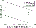
图23是表示生物分子固定构件的移动速度与DNA驱动时间的关系的图。FIG. 23 is a graph showing the relationship between the moving speed of the biomolecule-immobilizing member and the DNA driving time.
图24是表示二种聚合物混合分子((dA50dC50)m)的离子电流图示(trace)例的图。FIG. 24 is a diagram showing an example of an ion current trace (trace) of two types of polymer mixed molecules ((dA50dC50)m).
具体实施方式Detailed ways
以下,参照附图说明本发明的实施方式。各实施例中说明的所谓纳米孔,是设置于薄膜的贯通表里的纳米尺寸的孔。薄膜主要由无机材料形成。作为薄膜材料的例子,有SiN、SiO2、石墨烯(Graphene)、石墨(Graphite)、Si等,但此外也可以包含有机物质、高分子材料等。具有纳米孔的纳米孔薄膜形成于纳米孔器件上的一部分,具有上下不具有支持膜而缘部被纳米孔器件支持而在空中漂浮的结构。本说明书中所谓的生物分子中,包含核酸、蛋白质、氨基酸、长链高分子等。Hereinafter, embodiments of the present invention will be described with reference to the accompanying drawings. The so-called nanopores described in the respective examples are nano-sized pores provided in the thin film through the front and back surfaces. The thin film is mainly formed of an inorganic material. Examples of thin film materials include SiN, SiO 2 , Graphene, Graphite, Si, and the like, but may also include organic substances, polymer materials, and the like. A part of the nanoporous thin film with nanopores is formed on the nanoporous device, and has a structure in which the upper and lower supporting films are not provided, and the edge portion is supported by the nanoporous device and floats in the air. The term "biomolecules" in this specification includes nucleic acids, proteins, amino acids, long-chain polymers, and the like.
<实施例1><Example 1>
对本发明的具有输送控制机构的生物分子测定装置、和使用了该装置的生物分子的序列读取的例子进行说明。图1是说明生物分子测定装置的构成例的截面示意图。An example of a biomolecule measurement device having a transport control mechanism of the present invention and a sequence reading of a biomolecule using the device will be described. FIG. 1 is a schematic cross-sectional view illustrating a configuration example of a biomolecule measurement apparatus.
本实施例的生物分子测定装置100,具有通过纳米孔器件101而隔开的上下2个液槽,各液槽中充满电解质溶液102。作为电解质溶液,可使用KCl、NaCl、LiCl、MgCl2等。此外为了抑制生物分子的折叠,也能够对这些溶液混合存在4M以上的尿素(Urea)。此外,为了生物分子的稳定化,也能够混合存在缓冲剂。作为缓冲剂,可使用TE、PBS等。在纳米孔器件101形成有薄膜113,在薄膜113中的任一位置形成有纳米孔112。上下2个液槽经由被纳米孔器件101支持的薄膜113的纳米孔112而连通。在2个液槽分别以Ag/AgCl电极103a、103b与电解质溶液102接触的方式配置Ag/AgCl电极103a、103b,在电极103a、103b间连接有电源104和电流计109。电流计109与ADC、PC110连接,可以记录取得的电流值。另一方面,在上部的液槽设置有驱动机构105,与驱动机构控制单元106连接。在驱动机构105通过连接构件111而连接有生物分子固定构件(以下,简称为固定构件)107。固定构件107具有比薄膜113大的尺寸,在固定构件107的平坦的下表面固定生物分子108。The
如果固定构件107与形成有纳米孔112的薄膜113接触,则可能破坏薄膜113。因此,在被驱动机构105驱动的固定构件107朝向纳米孔器件101而降下时,为了防止固定构件107与薄膜113接触而设置有停止设备。本实施例的停止设备是,将纳米孔器件101的与薄膜113相比靠外侧的周围以堤坝的方式包围,在固定构件107与薄膜113之间形成空间的空间形成构件114。在空间形成构件114的中心形成的圆形空间中配置具有纳米孔112的薄膜113,薄膜113的尺寸比固定构件107的尺寸小。因此,朝向纳米孔器件101移动的固定构件107在与薄膜113接触前与空间形成构件114碰撞而停止,不会与薄膜113接触而破坏。薄膜的尺寸需要为保持薄膜强度和通过电压施加形成孔穴时不易形成二个以上孔穴的面积,因此以直径计为100~500nm左右是适当的,为了实现DNA一碱基分辨率,能够形成具有一碱基相当的有效膜厚的纳米孔的膜厚1nm左右是适当的,如果考虑保持薄膜的强度、生物分子固定构件表面的生物分子的固定高度摇摆,则空间形成构件的膜厚为200~500nm程度是适当的。本实施例中,薄膜113的尺寸为直径500nm,空间形成构件114的膜厚为250nm。If the fixing
纳米孔器件的制成法和纳米孔的形成法是已知的,例如记载于Itaru Yanagi etal.,Sci.Rep.4,5000(2014)。本实施例中,按以下步骤制作要形成纳米孔的薄膜。首先,在725μm厚的8英寸Si晶片的表面,成膜Si3N4/SiO2/Si3N412nm/250nm/100nm,在背面成膜Si3N4112nm。接下来,将表面最上部的Si3N4500nm见方、和背面的Si3N4 1038μm见方分别进行反应性离子蚀刻。进一步将通过背面的蚀刻而露出的Si基板利用TMAH(氢氧化四甲铵)进行蚀刻。Si蚀刻期间为了防止表面侧SiO的蚀刻而将晶片表面用保护膜(ProTEKTMB3primer andProTEKTMB3,Brewer Science,Inc.)覆盖。除去保护膜后,将以500nm见方露出的SiO层用BHF溶液(HF/NH4F=1/60,8min)除去。由此,可获得膜厚12nm的薄膜Si3N4露出的纳米孔器件。在该阶段,在薄膜不设置纳米孔。Methods of fabricating nanopore devices and forming nanopores are known, for example, as described in Itaru Yanagi et al., Sci. Rep. 4, 5000 (2014). In this embodiment, the following steps are used to fabricate a thin film on which nanopores are to be formed. First, Si 3 N 4 /SiO 2 /Si 3 N 4 12 nm/250 nm/100 nm was deposited on the surface of a 725 μm-thick 8-inch Si wafer, and Si 3 N 4 112 nm was deposited on the back surface. Next, the uppermost Si 3 N 4 on the front surface was 500 nm square, and the Si 3 N 4 on the back surface was 1038 μm square, respectively, by reactive ion etching. Further, the Si substrate exposed by the etching of the back surface was etched with TMAH (tetramethylammonium hydroxide). During the Si etching, the wafer surface was covered with a protective film (ProTEK ™ B3 primer and ProTEK ™ B3, Brewer Science, Inc.) in order to prevent the etching of the surface side SiO. After removing the protective film, the SiO layer exposed in a square of 500 nm was removed with a BHF solution (HF/NH 4 F=1/60, 8 min). In this way, a nanoporous device in which thin film Si 3 N 4 with a film thickness of 12 nm is exposed can be obtained. At this stage, no nanopores are provided in the film.
对从纳米孔器件露出的薄膜的纳米孔形成通过脉冲电压而按以下步骤进行。在将如上述那样操作而制成的纳米孔器件放置在生物分子测定装置前,通过Ar/O2等离子体(SAMCO Inc.,Japan)在10W、20sccm、20Pa、45sec的条件下将Si3N4薄膜亲水化。接下来,在经由纳米孔器件而分离成上下2槽的构成的生物分子测定装置中放置纳米孔器件后,充满1MKCl、1mM Tris-10mM EDTA、pH7.5溶液,在各槽导入Ag/AgCl电极。The nanopore formation of the thin film exposed from the nanopore device was performed by the pulse voltage as follows. Before placing the nanopore device fabricated as described above in a biomolecule assay device, Si 3 N was subjected to Ar/O 2 plasma (SAMCO Inc., Japan) under the conditions of 10 W, 20 sccm, 20 Pa, 45 sec. 4. The film is hydrophilized. Next, after placing the nanopore device in a biomolecule measurement device having two upper and lower chambers separated by the nanopore device, it was filled with a solution of 1MKCl, 1mM Tris-10mM EDTA, pH 7.5, and Ag/AgCl electrodes were introduced into each chamber. .
用于形成纳米孔的电压施加和形成纳米孔后经由纳米孔而流动的离子电流计测在该Ag/AgCl电极间进行。将下槽称为cis槽,将上槽称为trans槽,将cis槽电极侧的电压Vcis设定为0V,选择trans槽电极侧的电压Vtrans。选择的电压以脉冲发生器(41501B SMU ANDPulse Generator Expander,Agilent Technologies,Inc.)施加。各脉冲施加后的电流值用电流放大器(4156B PRECISION SEMICONDUCTOR ANALYZER,Agilent Technologies,Inc.)读取。用于形成纳米孔的电压施加和离子电流读取的过程由自制程序(Excel VBA,Visual Basic for Applications)控制。关于脉冲电压施加条件,通过根据在脉冲电压施加前形成于薄膜的孔径而选择取得的电流值条件(阈值电流),来依次增大孔径,获得了目标的孔径。孔径由离子电流值估算。条件选择的基准如表1所述。这里第n的脉冲电压施加时间由下式确定。Voltage application for forming the nanopore and ion amperometric measurement of the flow through the nanopore after the nanopore was formed were performed between the Ag/AgCl electrodes. The lower cell is referred to as a cis cell and the upper cell is referred to as a trans cell, the voltage V cis on the electrode side of the cis cell is set to 0V, and the voltage V trans on the electrode side of the trans cell is selected. The selected voltages were applied with a pulse generator (41501B SMU AND Pulse Generator Expander, Agilent Technologies, Inc.). The current value after each pulse was applied was read with a current amplifier (4156B PRECISION SEMICONDUCTOR ANALYZER, Agilent Technologies, Inc.). The process of voltage application and ionic current reading for nanopore formation was controlled by a home-made program (Excel VBA, Visual Basic for Applications). Regarding the pulse voltage application conditions, the current value condition (threshold current) was selected according to the pore size formed in the thin film before the pulse voltage application, and the pore size was sequentially increased to obtain the target pore size. Pore size is estimated from ionic current values. The criteria for condition selection are described in Table 1. Here, the nth pulse voltage application time is determined by the following equation.
tn=10-3+(1/6)(n-1)-10-3+(1/6)(n-2)其中n>2t n = 10-3+(1/6)(n-1) -10-3+(1/6)(n-2) where n>2
[表1][Table 1]
表1电压施加条件Table 1 Voltage application conditions
除了纳米孔的形成采用脉冲电压施加进行以外,也能够通过采用TEM的电子射线照射来进行(A.J.Storm et al.,Nat.Mat.2(2003))。In addition to the formation of nanopores by pulse voltage application, electron beam irradiation by TEM can also be performed (A.J.Storm et al., Nat.Mat.2 (2003)).
回到图1,如果经由Ag/AgCl电极103a、103b从电源104向上下2槽的液槽施加电压,则在纳米孔112的附近产生电场,在液体中带负电的生物分子108通过纳米孔112内。另一方面,生物分子108的末端被固定于固定构件107,因此由于电场,经由生物分子108而固定构件107、驱动机构105向下槽的方向被拉拽。Returning to FIG. 1 , if a voltage is applied from the
这里,为了精度良好地读取例如DNA的碱基序列,需要是在发生驱动机构的输出摇摆、和摇动原因的振动时,生物分子108的位移为不变化1个碱基的长度,即0.34nm以上的构成。Here, in order to read, for example, the base sequence of DNA with high accuracy, the displacement of the
接下来,对用于满足该要件的条件进行研究。如果将杨氏模量设为E,则E如下表示。Next, a condition for satisfying this requirement will be examined. If Young's modulus is E, E is represented as follows.
[式1][Formula 1]

这里,F为施加于体系的力,S为材料的面积,L为材料的长度,ΔL为受到施加的力时的位移量。可知在经由纳米孔沿上下施加1mV时,DNA所受到的力为0.24pN(UlrichF.Keyser et al.,Nat.Phys.2,473-477(2006))。由于解析中的施加电压的摇摆可能发生0.1mV左右,因此此时需要不位移0.34nm以上。因此,固定构件107与驱动机构105及其连接构件111的杨氏模量需要具有0.07(L/S)[μN/mm2]以上。Here, F is the force applied to the system, S is the area of the material, L is the length of the material, and ΔL is the displacement when the force is applied. It is known that when 1 mV is applied up and down through the nanopore, the force on DNA is 0.24 pN (Ulrich F. Keyser et al., Nat. Phys. 2, 473-477 (2006)). Since fluctuation of the applied voltage during the analysis may occur by about 0.1 mV, it is necessary not to shift by more than 0.34 nm at this time. Therefore, the Young's modulus of the fixing
此外,计测系统热稳定也是重要的。已知即使在没有热源的情况下,空间也具有0.1度的摇摆。因此,由体系使用的材料整体算出的、纳米孔器件-生物分子固定基板间的距离的温度变化需要为每0.1℃0.34nm以下。In addition, the thermal stability of the measurement system is also important. Space is known to have a 0.1 degree sway even in the absence of a heat source. Therefore, the temperature change of the distance between the nanopore device and the biomolecule-immobilized substrate calculated from the entire material used in the system needs to be 0.34 nm or less per 0.1°C.
因此,连接构件111优选使用不锈钢制或使用因瓦合金等制作的螺栓等。或者,也能够将固定构件107与驱动机构105真空吸附或压接而固定。驱动机构105由以压电元件为代表的压电材料形成,能够实现0.1nm/s以上的驱动。作为压电材料,可使用钛酸钡(BaTiO3)、锆钛酸铅(PZT)、氧化锌(ZnO)等。Therefore, the
生物分子108的末端与固定构件107的表面彼此可以通过共价键、离子键、静电相互作用、磁力等而结合。例如,在通过共价键而固定DNA时,可以固定经由APTES、戊二醛而进行了DNA末端修饰的DNA。为了利用上述结合,固定构件107利用成为APTES的基础的Si、SiO。作为其它共价键法,可以利用金硫醇键。对DNA的5’末端进行硫醇修饰,固定构件107的表面进行金蒸镀。蒸镀于固定构件107的金属种类此外还可以利用硫醇能够结合的Ag、Pt、Ti。The ends of the
利用离子键的方法是,通过实施使固定构件通过表面修饰而在溶液中带正电的处理,从而在带正电的固定构件表面固定带负电的生物分子的方法。作为阳离子性的聚合物,可使用聚苯胺、聚赖氨酸。在利用静电相互作用的情况下,可以在进行了APTES修饰的固定构件107的表面直接固定进行了氨基末端修饰的DNA。此外,作为基板表面,广泛利用硝酸纤维素膜、聚1,1-二氟乙烯膜、尼龙膜、聚苯乙烯基板。特别是硝酸纤维素膜被利用于微阵列技术。在利用磁力时,例如利用上述那样的结合在磁珠表面预先固定化DNA。进一步通过使用磁石材料作为固定构件107,从而使固定化了DNA的磁珠与固定构件107相互作用,通过磁力实现DNA固定化磁珠的吸引。作为磁性材料,可使用铁、硅钢、无定形磁性合金、纳米晶体磁性合金等。The method using the ionic bond is a method of immobilizing negatively charged biomolecules on the surface of the positively charged immobilization member by performing a treatment in which the immobilization member is positively charged in a solution by surface modification. As the cationic polymer, polyaniline and polylysine can be used. In the case of utilizing electrostatic interaction, the amino-terminal-modified DNA can be directly immobilized on the surface of the APTES-modified
在作为生物分子而测定蛋白质、氨基酸的情况下也同样地,可以实施对特异结合部位的修饰,利用同样的方法使其结合于固定基板。由此可以获得蛋白质中的结合部位的特定、和氨基酸的序列信息。Also in the case of measuring proteins and amino acids as biomolecules, the specific binding sites can be modified in the same way, and the binding sites can be bound to the immobilized substrate by the same method. Thereby, the specificity of the binding site in the protein and the sequence information of the amino acid can be obtained.
固定构件107上的生物分子108的固定密度由在纳米孔112周边形成的电场的扩展量来决定。图2是表示在纳米孔周边生成的电场和生物分子对纳米孔的导入例的示意图。如图2所示,在纳米孔112的周边扩展的电位梯度201在距离纳米孔112的距离L、纳米孔径d、薄膜的厚度t、施加的电压ΔV之间具有下述式2的关系,The immobilization density of the
[式2][Formula 2]

例如,在夹着形成于膜厚2.5nm的薄膜的直径1.4nm的纳米孔而施加100mV的电压的情况下,在距离纳米孔100nm的区域,传播0.1[V/μm]的电场。For example, when a voltage of 100 mV is applied across a nanopore with a diameter of 1.4 nm formed in a thin film with a thickness of 2.5 nm, an electric field of 0.1 [V/μm] propagates in a
这里,由生物分子的电迁移率μ、扩散系数D,求出生物分子被关在该电场中而导入到纳米孔的范围。如果将该范围设为Ldiff则由下式表示。Here, the range in which the biomolecules are trapped in the electric field and introduced into the nanopore is obtained from the electric mobility μ and the diffusion coefficient D of the biomolecules. If this range is set to L diff , it is represented by the following formula.
[式3][Formula 3]

将固定构件107与薄膜113最靠近时的距离设为l。此外,如果将生物分子在溶液中的有效长度设为b,则根据以上说明,生物分子固定间距a如下。The distance when the fixing
[式4][Formula 4]

为了实现上述,例如在固定构件107上修饰DNA时,如果除了目标的DNA以外,使用使进行了末端修饰的短链聚合物206混合存在的DNA溶液,则如图3所示,生物分子(DNA)108与进行了末端修饰的短链聚合物206混合存在而被固定,可以制作目标的DNA固定密度有效低的DNA固定构件。例如,如果使用包含20mer poly(dA)75%的DNA溶液来准备固定构件,则确认到使用具有2.5~3nm的孔径的纳米孔,可以排除在一个孔进入多条DNA的现象。即认为可以以约100nm间距固定。混合的短链聚合物的长度不限于2nm左右。In order to achieve the above, when DNA is modified on the fixing
图4是说明生物分子对固定构件的结合步骤和固定构件对生物分子测定装置的设置步骤的例子的示意图。电极省略图示。图4所示的测定前的准备工序包含3个工序。图4(a)所示的第1工序中,在固定构件107上固定生物分子108。图4(b)所示的第2工序中,将固定构件107与驱动机构105连接,插入到生物分子测定装置的上槽。图4(c)所示的第3工序中,在纳米孔器件101的上下的空间导入电解质溶液102。4 is a schematic diagram illustrating an example of a step of binding a biomolecule to an immobilization member and a step of installing the immobilization member to a biomolecule measurement device. Electrodes are omitted from illustration. The preparation process before the measurement shown in FIG. 4 includes three processes. In the first step shown in FIG. 4( a ), the
图5是表示生物分子对固定构件的结合步骤的其它例的示意图。电极省略图示。图5所示的测定前的准备工序包含2个工序。图5(a)所示的第1工序中,将固定构件107与驱动机构105连接,插入到生物分子测定装置的上槽。图5(b)所示的第2工序中,将能够与固定构件107结合的状态的生物分子108溶解的生物分子混合电解质溶液403注入到生物分子测定装置的上槽和下槽。FIG. 5 is a schematic diagram showing another example of the binding step of the biomolecule to the immobilization member. Electrodes are omitted from illustration. The preparation process before the measurement shown in FIG. 5 includes two processes. In the first step shown in FIG. 5( a ), the fixing
这里用于将生物分子与固定构件的表面结合的结合材料,为了极力减少非特异性的吸附,提高在固定构件的表面上进行目标的结合的密度,需要预先对固定构件的表面进行修饰。所谓结合材料,例如,在利用经由了APTES戊二醛的共价键来固定生物分子的情况下,是指APTES和戊二醛。在利用离子键来固定生物分子的情况下,是指基板表面的有机材料。The binding material used here to bind biomolecules to the surface of the immobilization member requires modification of the surface of the immobilization member in order to minimize nonspecific adsorption and increase the density of targeted binding on the surface of the immobilization member. The so-called binding material refers to APTES and glutaraldehyde in the case of immobilizing a biomolecule by, for example, a covalent bond via APTES glutaraldehyde. In the case of immobilizing biomolecules by ionic bonds, it refers to the organic material on the surface of the substrate.
在生物分子为长链DNA的情况下,特别是在多个鸟嘌呤连续并排那样的序列中,DNA的牢固的折叠成为问题。如果DNA发生折叠,则在纳米孔附近可能发生堵塞、不通过纳米孔等现象。因此,优选实施在高温特别是在60℃至98℃将固定了DNA的固定构件在水中加热10分钟至120分钟,骤冷直到4℃的处理。然后,在4℃或室温的KCl溶液中测定。When a biomolecule is a long-chain DNA, particularly in a sequence in which a plurality of guanines are consecutively arranged side by side, firm folding of the DNA becomes a problem. If the DNA is folded, clogging may occur in the vicinity of the nanopore, and phenomena such as failure to pass through the nanopore may occur. Therefore, a treatment of heating the DNA-immobilized immobilization member in water for 10 minutes to 120 minutes at a high temperature, particularly at 60°C to 98°C, and quenching to 4°C is preferably performed. Then, measure in KCl solution at 4°C or room temperature.
图6是表示固定构件的驱动步骤的示意图。电极省略图示。固定构件的驱动法包含图6所示的三个工序。图6(a)表示,通过图4或图5所示的步骤,要测定的生物分子108被固定在下表面的固定构件107被插入到生物分子测定装置的上部的液槽,在上下的液槽导入电解质溶液而进行测定准备的状态。FIG. 6 is a schematic diagram showing a driving step of the fixing member. Electrodes are omitted from illustration. The driving method of the fixing member includes three steps shown in FIG. 6 . Fig. 6(a) shows that, through the steps shown in Fig. 4 or Fig. 5, the
图6(b)所示的固定构件驱动的第1工序中,通过驱动机构控制单元106来驱动控制驱动机构105,将固定构件107向z轴下方驱动,使固定于固定构件107的生物分子108进入到在薄膜113的纳米孔112的附近生成的电位梯度201内。此时,如果生物分子108带负电,或在进行了带负电的修饰的情况下,受到来自电场的力,生物分子108要从未被固定的自由末端通过纳米孔112而移动到下部的液槽。生物分子108成为在通过纳米孔112而位于电位梯度201内的部分与固定在固定构件107上的末端之间被拉伸的状态。在纳米孔112内导入生物分子可以由离子电流监测。In the first step of driving the fixing member shown in FIG. 6( b ), the
图6(c)所示的第2工序中,通过驱动机构105进一步将固定构件107向z轴方向下方驱动,使其与形成在纳米孔器件101上的空间形成构件114接触,这里停止由驱动机构105引起的固定构件107的移动。通过在薄膜113的上方存在空间形成构件114,从而避免固定构件107与薄膜113接触,可以防止薄膜113被破坏。在完成了第2工序的时刻,薄膜113的纳米孔112内未进入生物分子108的情况下,可以通过停止驱动机构105的驱动一定时间来提高导入概率。图6(c)中一并显示驱动机构105的侧面示意图和固定构件107的俯视示意图。在固定构件107的下表面如图示那样设置有切口(slit)507,即使在固定构件107与空间形成构件114接触的状态下,也在配置于上下的槽的电极之间确保了电流通路。In the second step shown in FIG. 6( c ), the fixing
图6(d)所示的第3工序中,通过驱动机构控制单元106将驱动机构105向与纳米孔器件101分离的方向驱动。此时生物分子108一边在电场被拉伸,一边被固定构件107拉拽而在纳米孔112内沿上方向移动,从而在这期间由离子电流的变化量读取生物分子的序列。用电流计109读取的信号值根据需要被放大,被PC110记录。In the third step shown in FIG. 6( d ), the
第2工序中固定构件107与空间形成构件114接触的时刻成为第3工序中进行的生物分子特性解析的解析开始点。因此,生物分子的全长中,距离固定点为空间形成构件114的高度的区域不通过纳米孔112内而不能解析。这里如图7所示,在固定构件107上固定生物分子108时,通过经由空间形成构件114的高度的连接件901而与固定构件107结合,从而能够读取生物分子108中的全部序列。The timing at which the fixing
图8为表示离子电流信号的检测例的示意图。将固定构件相对于纳米孔器件的位置关系的示意图示于上部,将离子电流信号变化的图示于中部,将驱动机构位移的图示于下部。下部的驱动机构位移z和纳米孔器件与固定构件之间的距离对应。此外,将与离子电流信号中的特征点对应的固定构件与纳米孔器件的位置关系以箭头表示。FIG. 8 is a schematic diagram showing an example of detection of an ion current signal. The schematic diagram of the positional relationship of the fixing member with respect to the nanopore device is shown in the upper part, the diagram of the change of the ion current signal is shown in the middle part, and the diagram of the displacement of the driving mechanism is shown in the lower part. The displacement z of the lower driving mechanism corresponds to the distance between the nanopore device and the fixing member. In addition, the positional relationship between the fixing member and the nanopore device corresponding to the characteristic point in the ion current signal is indicated by an arrow.
如果参照图8,则在固定构件107与纳米孔器件接近前,可获得与纳米孔径对应的离子电流信号I0。在生物分子108进入纳米孔112时,发生与生物分子的平均直径对应的离子电流量的减少。此时生物分子通过纳米孔的速度不是固定构件的驱动速度,而是生物分子的自由电泳的速度。这是因为,在生物分子从电场外进入电场内时,生物分子折叠弯曲,因此没有受到端部被固定于固定构件所带来的影响。此时,得不到测定分辨率,取得的离子电流值表示依存于生物分子平均直径的平均的电流值Ib。Referring to FIG. 8 , before the fixing
在固定构件107与纳米孔器件的空间形成构件114接触后,通过驱动机构105来提升生物分子时的生物分子的输送速度与固定构件105的移动速度变得相等,因此可以以对于特性分辨率而言所需的速度进行输送。例如可以认为在以闭锁电流量计测DNA链所含的各个碱基种类的差异时,根据计测时的电流噪声和DNA分子的摇摆的时间常数,需要使DNA的纳米孔通过速度为每1碱基100μs以上。因此控制驱动机构105而将固定构件107以比每1碱基100μs以上慢的速度向上方移动,从而获得反映生物分子的碱基序列的信号。另一方面,解析吞吐量需要维持得高,因此期望每一碱基不花费10ms以上。即,驱动机构优选将生物分子固定构件以34nm/sec~34μm/sec之间的速度驱动。After the fixing
这里生物分子的表示序列的数据的取得方法不限于离子电流的变化量。在纳米孔器件上形成隧道电流用电极,在其附近形成纳米孔的情况下,通过隧道电流量变化可以解析生物分子的序列(Makusu Tsutsui et at,Nat.Nanotechnol.5,286-290(2010))。此外,在FET器件形成纳米孔的情况下,可以由电荷量变化解析序列。或者,也能够进行使用了光的解析,在该情况下,可以由吸收量、反射量、发光波长等来解析生物分子的序列(Ping Xieet al.,Nat.Nanotechnol.7,119-125(2012))。本发明中,也可以代替离子电流,而使用这些已知的方法来解析在纳米孔112内移动的生物分子。Here, the method of acquiring data representing the sequence of biomolecules is not limited to the amount of change in ion current. When an electrode for tunneling current is formed on a nanopore device and a nanopore is formed near the nanopore, the sequence of biomolecules can be analyzed by changing the amount of tunneling current (Makusu Tsutsui et at, Nat. Nanotechnol. 5, 286-290 (2010)). Furthermore, in the case of FET devices forming nanopores, the sequence can be resolved from changes in the amount of charge. Alternatively, analysis using light can also be performed, and in this case, the sequence of biomolecules can be analyzed from the amount of absorption, amount of reflection, emission wavelength, etc. (Ping Xie et al., Nat. Nanotechnol. 7, 119-125 (2012)) . In the present invention, these known methods may be used instead of ion current to analyze biomolecules moving in the
图9是表示防止固定构件与薄膜接触的停止设备的其它例的示意图。图9中也一并显示包含驱动机构105的固定构件107的侧面示意图、和具有切口603的仰视图。该例子中,不是在纳米孔器件101上,而是以从固定构件107的下表面向下方突出的方式对空间形成构件601进行了加工。空间形成构件601,以在与薄膜113相比靠外侧的位置与纳米孔器件101接触的方式,形成在固定构件107的下表面外周、或下表面四个角或对置的二边。即,空间形成构件601设置在固定构件107的下表面的与和薄膜113对置的区域相比靠外侧的至少一部分。在固定构件107向纳米孔器件101的方向移动时,通过空间形成构件601而在固定构件107与薄膜113之间形成空间,防止薄膜113与固定构件107接触而被破坏。FIG. 9 is a schematic diagram showing another example of the stop device for preventing the contact of the fixing member and the film. FIG. 9 also shows a schematic side view of the fixing
图10是表示防止固定构件与薄膜接触的停止设备的其它例的示意图。图10(a)表示固定构件与纳米孔器件接触前的状态,图10(b)表示固定构件与纳米孔器件接触后的状态。停止设备只要可以在固定构件107与薄膜113之间提供用于避免两者接触的空间即可。本例的停止设备是,在纳米孔器件101的上表面、和固定构件107的下表面的与薄膜对应的区域的外侧的至少一部分分别配置电极702a和电极702b,由电极702a、702b间的静电容量变化检测固定构件107与纳米孔器件101间的相对距离,监测两者接触。在电极702a、702b间施加的电压根据假定电流量和计测电流而选择。此外,为了防止电极的腐蚀、氧化,也能够通过脉冲电压施加来计测。使固定构件107向纳米孔器件101的方向驱动,以在纳米孔器件101与固定构件107接近时由电极702a、702b取得的信号变化作为基础来检测两者间的距离,停止驱动机构105的驱动。代替取得静电容量变化的信号,也能够由短路监测接触。在构成停止设备的电极702a、702b间施加电压期间,不对计测用电极103a、103b施加电压。FIG. 10 is a schematic view showing another example of the stop device for preventing the contact of the fixing member and the film. FIG. 10( a ) shows a state before the fixing member is in contact with the nanoporous device, and FIG. 10( b ) shows a state after the fixing member is in contact with the nanoporous device. The stopping device is only required to provide a space between the fixing
图11是表示防止固定构件与薄膜接触的停止设备的其它例的示意图。图11(a)所示的例子中,将电极801、802仅配置在纳米孔器件101上而在电极间配线,由在固定构件107与纳米孔器件101接近时的电流量变化检测固定构件107与纳米孔器件101间的相对距离。电极801、802配置在纳米孔器件101的上表面的薄膜113的外侧的区域的外周、四个角或对置的二边。图11(b)所示的例子中,在固定构件107的下表面配置电极803、804而在电极间配线,以同样的机理检测固定构件107与纳米孔器件101间的相对距离。电极803、804只要配置在固定构件107的下表面中的与薄膜113对应的区域的外侧的四个角或对置的二边即可。FIG. 11 is a schematic view showing another example of the stop device for preventing the contact of the fixing member and the film. In the example shown in FIG. 11( a ), the
在将4个电极配置在四个角的情况下,也能够利用于固定构件107的平衡工具。在该情况下,使驱动机构105具有倾斜度调整功能,以由4处取得的电流值几乎一致的方式,调整驱动机构105的倾斜度。例如,在4个角设置独立的测角计,基于由4处取得的电流值对其进行手动或自动调整。When the four electrodes are arranged at the four corners, it can also be used as a balancing tool for the fixing
图12是表示对图11(a)所示的纳米孔器件101上的电极配置例的俯视示意图。图12(a)是纳米孔器件101上的薄膜113、传感器配线806、和电极取出配线807的配置图。图12(b)、图12(c)是传感器配线放大图,图12(b)表示一种对电极的例子,图12(c)表示在薄膜113的周边部的4处环状地配置了对电极808的例子。这里,在将图12(b)所示的电极长度L设为10μm,电极间隔s设为0.4μm~2μm而设计的电极间,施加1V的电压,并且监测在使固定构件107与纳米孔器件101接近时的电极间电流变化。FIG. 12 is a schematic plan view showing an example of electrode arrangement on the
图13是表示以固定构件-纳米孔器件间距离h为10μm时流动的电流量标准化而表示的距离h与电流量的关系的图。如图13所示,如果固定构件与纳米孔器件间距离相距7μm以上,则可知电流量的距离h依赖性几乎没有,但在其以下距离与电流减少量具有相关。因此,通过取得这样的距离h与电流量的相关关系,从而能够进行固定构件的高度调整。13 is a graph showing the relationship between the distance h and the current amount expressed by normalizing the amount of current flowing when the distance h between the fixing member and the nanopore device is 10 μm. As shown in FIG. 13 , when the distance between the fixing member and the nanopore device was 7 μm or more, it was found that the distance h dependence of the current amount was almost non-existent, but the distance below it correlated with the current reduction amount. Therefore, by obtaining such a correlation between the distance h and the current amount, the height of the fixing member can be adjusted.
作为固定构件的驱动法的其它例,也有将固定构件107上的生物分子108预先拉伸,同时向纳米孔附近临近的方法。图14、图15是表示采用具有生物分子的预先拉伸机构的生物分子测定装置进行的固定构件的驱动法的例子的截面示意图。As another example of the driving method of the fixing member, there is also a method in which the
如图14(a)所示,本例的生物分子测定装置中,固定构件107、和纳米孔器件101分别具备电极1202a、1202b。最初,通过电路转换控制器1206,对与电极1202a、1202b连接的电路1207连接电源,在固定构件107与纳米孔器件101之间形成电位梯度1203。如此,通过电位梯度1203,带负电的生物分子108在固定构件107与纳米孔器件101之间被拉伸。As shown in FIG. 14( a ), in the biomolecule measurement apparatus of this example, the fixing
接下来,如图14(b)所示,将驱动机构105驱动,向下方驱动直到固定构件107与纳米孔器件101的空间形成构件114接触为止。此时,如图14(c)的放大图所示,在电源与连接电极103a、103b的电路1208连接时理应在纳米孔周边生成的假定电场1209的范围内进入生物分子108。Next, as shown in FIG. 14( b ), the
接下来,如图15(a)所示,在固定构件107与纳米孔器件101的空间形成构件114接触时,从与电极1202a、1202b连接了的电路1207,向在纳米孔周边形成电场的电路1208切换电源的连接。如图15(b)所示,通过在纳米孔周边形成电位梯度201,从而生物分子的前端插入到纳米孔。Next, as shown in FIG. 15( a ), when the fixing
存在经过图14(b)所示的工序后,生物分子的前端未进入到纳米孔内的情况、和虽然概率小但如图14(d)的放大图所示,前端进入到纳米孔的情况。仅在前端未进入到纳米孔内而进入到电场区域内的情况下,能够从生物分子的前端读取碱基。There are cases where the tip of the biomolecule does not enter the nanopore after the process shown in Fig. 14(b), and there is a case where the tip of the biomolecule enters the nanopore as shown in the enlarged view of Fig. 14(d) although the probability is small. . Only when the tip does not enter the nanopore but enters the electric field region, the base can be read from the tip of the biomolecule.
图16是表示从生物分子的前端读取的信号的例子的示意图。将离子电流信号变化的图示于中部,将驱动机构位移的图示于下部。下部的驱动机构位移z和纳米孔器件与固定构件之间的距离对应。此外,关于离子电流信号中的特征点,将上部所示的固定构件与纳米孔器件的对应以箭头表示。FIG. 16 is a schematic diagram showing an example of a signal read from the front end of a biomolecule. The graph of the change of the ion current signal is shown in the middle part, and the graph of the displacement of the drive mechanism is shown in the lower part. The displacement z of the lower driving mechanism corresponds to the distance between the nanopore device and the fixing member. In addition, regarding the characteristic points in the ion current signal, the correspondence between the fixing member shown in the upper part and the nanopore device is indicated by an arrow.
在固定构件与纳米孔器件接近前,可获得与纳米孔径对应的离子电流信号I0。将电源与电极103a、103b连接而在纳米孔的周围形成了电位梯度201时,生物分子108的前端进入到电位梯度201内,因此如果使驱动机构105向z轴下方驱动,则生物分子108从自由末端依次导入到纳米孔112内。此时由于生物分子108不存在弯曲,因此以利用驱动机构控制单元106设定的速度而驱动生物分子,能够解析与生物分子的各序列对应的特性。因此,生物分子108导入到纳米孔112后直到固定构件107与纳米孔器件101接触为止的时间读取的信号、和将驱动机构105沿z轴上方向开始驱动后生物分子末端从纳米孔112脱出为止的时间读取的信号,如图16所示,成为以接触的时间为中心而对称的信号。Before the fixing member approaches the nanopore device, the ionic current signal I 0 corresponding to the nanopore size can be obtained. When the power supply is connected to the
固定于固定构件107的生物分子中,与最初测定的生物分子不同的生物分子的读取,可以通过使驱动机构105向xy方向驱动来实现。图17是生物分子测定装置的局部的截面示意图和驱动机构105的俯视示意图。如俯视示意图所示,通过将驱动机构105向xy方向,即与薄膜113的面平行的方向驱动,可以使其它生物分子通过纳米孔112,实现固定构件107上的多个生物分子的解析。Among the biomolecules immobilized on the
使用图18所示的纳米孔附近的放大图来说明用于实现多个生物分子的解析的条件。图18(a)是表示进行第1生物分子1405的特性解析时的具有纳米孔112的薄膜113、固定构件107的位置关系的截面示意图。这里在解析第2生物分子1406的情况下,通过驱动机构105使固定构件107仅以与电位梯度201的直径相同距离向纳米孔薄膜113的面平行地移动。图18(b)是表示移动后的具有纳米孔112的薄膜113与固定构件107的位置关系的截面示意图。通过该移动,在电位梯度201的范围内,可以形成第1生物分子1405一定不会进入的状态。然后,通过驱动机构105将固定构件107朝向薄膜113驱动,能够将第2生物分子1406导入到纳米孔112进行解析。Conditions for realizing the analysis of a plurality of biomolecules will be described using the enlarged view of the vicinity of the nanopore shown in FIG. 18 . 18( a ) is a schematic cross-sectional view showing the positional relationship between the
<实施例2><Example 2>
以下说明使用本发明的生物分子测定装置来测定生物分子的步骤的实施例。在以下全部工序中,经由纳米孔而流动的离子电流I通过放大器计测。此外,在上下2槽的液槽各自插入的一对Ag/AgCl电极间施加一定电压,取得与纳米孔的尺寸对应的离子电流量I0。The following describes an example of a procedure for measuring a biomolecule using the biomolecule measuring apparatus of the present invention. In all the following steps, the ion current I flowing through the nanopore was measured by an amplifier. In addition, a constant voltage was applied between a pair of Ag/AgCl electrodes inserted into the liquid tanks of the upper and lower tanks, and the amount of ionic current I 0 corresponding to the size of the nanopore was obtained.
图19是表示读取作为生物分子的DNA的碱基序列的方法的例子的说明图。图19的上部显示DNA碱基序列解析中的固定构件和纳米孔器件的代表性的2个的位置关系。图19的中部显示离子电流变化,下部显示固定构件107的位移。下部的位移z和固定构件107与纳米孔器件101之间的距离对应。此外,将改变了利用驱动机构105进行的固定构件107的驱动方向的时刻、和此时的固定构件107与纳米孔器件101的位置关系示于图中。中部的黑箭头表示取上部左侧图示的第1位置关系,白箭头表示取上部右侧图示的第2位置关系。FIG. 19 is an explanatory diagram showing an example of a method for reading the base sequence of DNA as a biomolecule. The upper part of FIG. 19 shows the positional relationship between the fixing member and the typical two nanopore devices in DNA base sequence analysis. The middle part of FIG. 19 shows the ion current change, and the lower part shows the displacement of the fixing
如果通过驱动机构105向z轴下方驱动固定构件107,则生物分子108的自由末端进入到纳米孔中,生物分子在被固定于固定构件的末端与纳米孔之间被拉伸。此时,离子电流与生物分子108的平均直径尺寸对应而减少,成为Ib。生物分子从外进入到电位梯度201内时,生物分子折叠,因此不是以固定构件的移动速度,而是以生物分子的自由电泳的速度通过纳米孔内,此时的离子电流值不是表示各碱基来源的电流值,而是表示依存于生物分子平均直径的平均的电流值Ib。When the fixing
然后,固定构件107通过驱动机构105而进一步向z轴下方驱动,但由于空间形成构件114向z轴下方的移动受阻而移动停止。将此时的固定构件107、生物分子108、纳米孔器件101的位置关系作为第1位置关系而示于图19上部左侧。Then, the fixing
然后由于提升生物分子时的生物分子的输送速度与固定构件107的驱动速度变得相等,因此可以以一碱基分解所需的速度(<3.4nm/ms)输送生物分子。因此可获得反映生物分子的碱基序列的信号。这样在通过驱动机构105而将固定构件107向z轴上方驱动的过程中,可以读取在纳米孔112中移动的生物分子108的序列信息。生物分子108中未被固定的自由末端从纳米孔112脱出,并且进入到纳米孔周边的电位梯度201中的期间,生物分子108从固定构件107与纳米孔周边的电位梯度201两者受到反方向的力,被拉伸。将此时的固定构件107、生物分子108、纳米孔器件101的关系示于图19上部右侧。此外,由于生物分子108从纳米孔112脱出,因此离子电流量恢复到I0。检测该电流值的变化,停止利用驱动机构105进行的固定构件107的驱动。Then, since the transport speed of the biomolecules when the biomolecules are lifted and the driving speed of the fixing
再次通过驱动机构105将固定构件107向z轴下方驱动而将生物分子108从自由端通入到纳米孔,这期间读出生物分子108的碱基序列。此时,在末端被固定于固定构件107的状态下,生物分子108的另一方的自由末端进入到电位梯度201内,因此生物分子108作为整体被拉伸。因此,关于读取的信号,在纳米孔中从自由末端以驱动机构105的驱动速度通过,因此能够进行高精度的读取。此外,向z轴上方驱动期间对读取的序列从反方向读取,计测反映该序列而对称地变化的离子电流。再次在固定构件107与空间形成构件114接触时,停止固定构件107的驱动。The fixing
以后通过上升下降的重复,直到产生必要的序列读取精度为止反复持续读出。从固定构件107与纳米孔器件101接触的位置到离子电流值变为I0的位置的位移1505反映出生物分子的长度。Then, by repeating the rising and falling, the reading is repeated and continued until the necessary sequence reading accuracy is obtained. The
<实施例3><Example 3>
接下来,对将生物分子测定装置并列化的实施例进行说明。本发明的生物分子测定装置与并列化的纳米孔器件的亲和性良好。通过并列化而能够将同种生物分子同时测定,因此能够推测吞吐量的提高。这里,显示针对并列化的3种例子。Next, an example in which a biomolecule measurement apparatus is parallelized will be described. The biomolecule measurement device of the present invention has good affinity with the parallel nanopore device. By parallelizing, the same biomolecules can be measured simultaneously, so it is possible to estimate an improvement in throughput. Here, three examples of parallelization are shown.
图20(a)是表示具有并列化的纳米孔器件的生物分子测定装置的第1例的截面示意图。该例子中,多个纳米孔器件1604在横向上相邻配置,在多个纳米孔器件1604的上部,配置有共同的1个驱动机构105和固定构件107。固定构件107具有仅仅覆盖多个纳米孔器件整体的面积。并列化的多个纳米孔器件1604具备各自独立的液槽,在各纳米孔器件的液槽配置有阵列电极1608的一个,阵列电极1608分别与放大器连接。在并列化了的多个纳米孔器件1604的上部共同设置有1个液槽,在该液槽配置有相对阵列电极1608共同的对电极(共同电极)1609。在并列化了的纳米孔器件的侧方,设置有与多个纳米孔器件共同的空间形成构件1610。各个纳米孔器件1604所具备的液槽经由设置于该纳米孔器件1604的各个纳米孔而与上部的液槽连通。FIG. 20( a ) is a schematic cross-sectional view showing a first example of a biomolecule measurement apparatus having nanopore devices arranged in parallel. In this example, a plurality of
在固定构件107的下表面结合有多个生物分子108。如果使驱动机构105向z轴下方降下,则固定构件107上的生物分子108通过设置于各纳米孔器件的纳米孔中。通过本方式能够使用多个纳米孔同时进行多个生物分子的计测,因此计测吞吐量提高。A plurality of
图20(b)是表示具有并列化的纳米孔器件的生物分子测定装置的第2例的截面示意图。该例子中,在多个并排的纳米孔器件1604的上部,配置有一个驱动机构105。在纳米孔器件1604连接有阵列电极1608。在多个纳米孔器件1604的上部共同设置有1个液槽,配置有相对各阵列电极为共同的对电极1609。在并列化了的纳米孔器件1604的侧方,设置有与多个纳米孔器件共同的空间形成构件1610。驱动机构105连接有多个固定构件,分别固定有不同种类的生物分子。由此,能够实现同时进行不同的生物分子的特性解析。FIG. 20( b ) is a schematic cross-sectional view showing a second example of a biomolecule measurement apparatus having nanopore devices arranged in parallel. In this example, a
图示的例子中,在驱动机构105连接有第1固定构件107与第2固定构件1605的2个生物分子固定构件,在第1固定构件结合有第1生物分子108,在第2固定构件1605结合有第2生物分子1606。通过本方式,不仅能够对一种样品使用多个纳米孔,而且能够同时计测多个种类的样品,计测吞吐量提高。In the example shown in the figure, two biomolecule immobilizing members, a first immobilizing
图20(c)是表示具有并列化的纳米孔器件的生物分子测定装置的第3例的截面示意图。该例子中,在多个并排的纳米孔器件1604的上部,配置有多个驱动机构。在各个驱动机构分别连接有固定构件,分别固定有不同种类的生物分子。空间形成构件也能够每个固定构件都设置。FIG. 20( c ) is a schematic cross-sectional view showing a third example of a biomolecule measurement apparatus having nanopore devices arranged in parallel. In this example, a plurality of driving mechanisms are arranged above the plurality of
图示的例子中配置有第1驱动机构105和第2驱动机构1607,第1固定构件107结合有第1生物分子108,第2固定构件1605结合有第2生物分子1606。相对于第1固定构件107设置有第1空间形成构件1611,相对于第2固定构件1605设置有第2空间形成构件1612。第1空间形成构件1611与第2空间形成构件1612的膜厚不同。由此即使是长度不同的生物分子,也能够进行独立的高度调整。在形成于纳米孔器件的空间形成构件中形成有切口等,在固定构件下降,与空间形成构件接触时,成为充满纳米孔上部的溶液对每个样品都不独立那样的构成。由此配置在纳米孔上部的电极仅为共同电极1609即可。In the illustrated example, a
在任何例子中,纳米孔的个数a与固定构件上的生物分子的数b的大小关系都为a<b,通过将生物分子密密地结合在固定构件上,从而使固定构件朝向纳米孔器件而垂直降下时,一定会在纳米孔内导入生物分子。In any case, the size relationship between the number a of nanopores and the number b of biomolecules on the immobilization member is a<b, and the immobilization member faces the nanopore by densely binding the biomolecules to the immobilization member. When the device is lowered vertically, biomolecules must be introduced into the nanopore.
<实施例4><Example 4>
示出作为用于将生物分子固定于固定构件的其它手段,使用了磁珠的实施例。这里,通过作为生物分子测定装置而使用图20(a)所示的装置的例子进行说明。其中,固定构件由磁石材料构成。An embodiment using magnetic beads is shown as another means for immobilizing biomolecules to the immobilization member. Here, an example of using the device shown in FIG. 20( a ) as a biomolecule measurement device will be described. The fixing member is made of magnet material.
图21是说明使用磁珠将生物分子固定于固定构件,进行测定的步骤的截面示意图。生物分子准备预先固定化于磁珠的生物分子。FIG. 21 is a schematic cross-sectional view illustrating a procedure for immobilizing a biomolecule on an immobilization member using magnetic beads and performing measurement. Biomolecules prepare biomolecules pre-immobilized on magnetic beads.
第1工序中,如图21(a)所示,在配置在并列化的纳米孔器件1604的Ag/AgCl电极1608与共同电极1609间施加电压而在各纳米孔的周围的电解质溶液中生成电场,使固定于磁珠的生物分子1704通过电泳而泳动,在并列化的纳米孔器件1604的纳米孔导入生物分子。这里,监测各纳米孔来源的离子电流,由离子电流的变化率,可以确认在纳米孔进入生物分子的有效的纳米孔器件。In the first step, as shown in FIG. 21( a ), a voltage is applied between the Ag/
第2工序中,如图21(b)所示,将第1工序中的经由纳米孔的电压施加继续进行,同时通过驱动机构105将固定构件107如箭头所示那样朝向纳米孔器件1604驱动,通过磁力将磁珠向固定构件107吸引使其固定。In the second step, as shown in FIG. 21( b ), while the voltage application through the nanopore in the first step is continued, the fixing
第3工序中,如图21(c)所示,通过驱动机构105将固定构件107如箭头所示那样向与纳米孔器件1604分离的方向以受控制的速度驱动,用电流计检测起因于在纳米孔中移动的生物分子而变化的离子电流,记录于PC。由压电元件形成的驱动机构105可以以任意速度驱动固定构件107,特别是在读出DNA的序列的情况下,通过使固定化于磁珠的DNA以3.4nm/ms以下的速度在纳米孔内移动从而能够进行高精度的读取。In the third step, as shown in FIG. 21( c ), the fixing
根据本实施例,不需要纳米孔与生物分子的初期的对位。此外,能够扩散到在纳米孔附近生成的电场内而在纳米孔内导入生物分子,因此可以降低并列化的纳米孔内中的生物分子不通过的纳米孔存在的概率。According to this embodiment, the initial alignment of the nanopore and the biomolecule is not required. In addition, since biomolecules can be introduced into the nanopore by diffusing into the electric field generated near the nanopore, the probability of existence of the nanopore through which the biomolecules in the parallel nanopores do not pass can be reduced.
<实施例5><Example 5>
图22是表示伴随利用驱动机构进行的固定构件的驱动的闭锁电流消除的状况的图。FIG. 22 is a diagram showing a state in which the latching current is eliminated due to the driving of the fixing member by the drive mechanism.
使用图1所示的生物分子测定装置,将在进行了APTES/戊二醛修饰的表面固定了链长5k的ss-poly(dA)的固定构件靠近直到纳米孔器件的纳米孔附近。其结果是,如图22(a)所示,确认到闭锁信号,如果将固定构件从纳米孔器件分离,则闭锁信号消除了。在图22(b),显示与图22(a)同一时间下的固定构件的轨迹。随着计数位移增加,纳米孔器件与固定构件接近。确认到离子电流的减少后约1秒后,停止利用驱动机构进行的固定构件的驱动。在约10秒后,开始拉开纳米孔器件与固定构件的距离,再次,在离子电流增大的时刻(经过30秒后)再次使驱动机构的驱动停止。这表示,如果将固定了DNA的固定构件与纳米孔靠近则离子电流减少,通过从纳米孔远离来恢复到原来的电流值,因此通过利用驱动机构进行的固定构件的驱动,产生DNA对纳米孔的导入、脱出。Using the biomolecule measurement apparatus shown in FIG. 1 , the immobilization member to which ss-poly(dA) with a chain length of 5k was immobilized on the APTES/glutaraldehyde-modified surface was brought close to the vicinity of the nanopore of the nanopore device. As a result, as shown in FIG. 22( a ), the latch signal was confirmed, and when the fixing member was separated from the nanopore device, the latch signal was eliminated. In Fig. 22(b), the trajectory of the fixing member at the same time as Fig. 22(a) is shown. As the count displacement increases, the nanopore device approaches the immobilization member. About 1 second after the reduction of the ion current was confirmed, the driving of the fixing member by the driving mechanism was stopped. After about 10 seconds, the distance between the nanopore device and the fixing member was started to be widened, and the driving of the driving mechanism was stopped again at the time when the ion current increased (after 30 seconds). This means that when the DNA-immobilized immobilization member is brought closer to the nanopore, the ionic current decreases, and the current value is restored to the original current value by moving away from the nanopore. Therefore, the driving of the immobilization member by the driving mechanism generates DNA-to-nanopore import and exit.
将从为了将固定构件从纳米孔器件分离而开始驱动驱动机构的时间到闭锁信号消除的时间(DNA驱动时间),如图22(b)所示那样定义为tout。另一方面,由与驱动机构的设定速度对应的计数速度的关系求出固定构件的移动速度。将取得的DNA驱动时间(tout)相对于各固定构件的移动速度的关系示于图23。图中的曲线为实验值。这里,各计测中的、DNA驱动距离即DNA导入到纳米孔内的最大长度由通过DNA闭锁纳米孔后固定构件的驱动停止的位置来决定。利用驱动机构进行的固定构件的驱动,目视确认显示出在纳米孔进入DNA的闭锁信号并手动停止,因此可以认为实际上DNA进入纳米孔直至固定构件的驱动停止为止最短花费约一秒左右。因此,最短为60-100nm程度的DNA一定进入到纳米孔。The time from the time when the driving mechanism is started to be driven to separate the fixing member from the nanopore device to the time when the latch signal is eliminated (DNA driving time) is defined as t out as shown in FIG. 22( b ). On the other hand, the movement speed of the fixing member is obtained from the relationship of the count speed corresponding to the set speed of the drive mechanism. FIG. 23 shows the relationship between the obtained DNA driving time (t out ) and the moving speed of each immobilization member. The curve in the figure is the experimental value. Here, the DNA driving distance in each measurement, that is, the maximum length of DNA introduced into the nanopore, is determined by the position at which the driving of the fixing member stops after the nanopore is blocked by the DNA. The actuation of the fixation member by the drive mechanism was visually confirmed to show a latch signal for entering the DNA in the nanopore and was manually stopped. Therefore, it is considered that it took approximately one second at least for DNA to actually enter the nanopore until the drive of the fixation member stopped. Therefore, DNA with a shortest length of about 60-100 nm must enter the nanopore.
在图23中,实线是由固定的DNA的长度求出的最大DNA驱动时间的计算值。此外,虚线是60nm的DNA进入时花费的最小DNA驱动时间的计算值。由于实验上计测出的DNA驱动时间落入实线到虚线的范围内,因此取得的闭锁信号来源于固定构件上的DNA,实测值可以认为是妥当的。此外实测的DNA驱动时间分布在固定构件的移动速度越慢,则DNA驱动时间越长的方向。认为这是表示固定构件上的DNA依存于驱动机构的驱动速度而在纳米孔内输送的结果。In Fig. 23, the solid line is the calculated value of the maximum DNA driving time obtained from the length of the fixed DNA. In addition, the dotted line is the calculated value of the minimum DNA drive time taken for DNA entry at 60 nm. Since the DNA driving time measured experimentally falls within the range from the solid line to the dashed line, the obtained blocking signal is derived from the DNA on the immobilization member, and the measured value can be considered appropriate. In addition, the measured DNA driving time is distributed in the direction that the slower the moving speed of the fixed member, the longer the DNA driving time. This is considered to indicate that the DNA on the immobilization member was transported in the nanopore depending on the driving speed of the driving mechanism.
图24是表示将dA50dC50的聚合物反复延伸的分子((dA50dC50)m)同样地结合于固定构件并计测而得的结果的图。如果使固定构件与纳米孔器件接近,则确认了图22中取得那样的闭锁信号。如果解析闭锁后的电流,则获得了二能级的信号。这样,使生物分子与固定构件结合,降低分子通过速度,从而能够计测与分子种类对应的闭锁信号强度不同的状况。FIG. 24 is a diagram showing the result of measurement obtained by similarly binding a molecule ((dA50dC50)m) of a polymer of dA50dC50 repeatedly to an immobilization member. When the fixing member and the nanopore device were brought close to each other, it was confirmed that a latching signal was obtained as shown in FIG. 22 . If the latched current is analyzed, a two-level signal is obtained. In this way, by binding the biomolecules to the immobilization member and reducing the molecular passing speed, it is possible to measure a situation where the intensities of the blocking signals differ depending on the molecular species.
另外,本发明不限定于上述实施例,包含各种变形例。例如,上述实施例是为了易于理解说明本发明而进行了详细说明,不一定限定于具备说明的全部构成。此外,能够将某一实施例的构成的一部分置换成其它实施例的构成,此外,也能够在某一实施例的构成中加上其它实施例的构成。此外,关于各实施例的构成的一部分,能够进行其它构成的追加、删除、置换。In addition, the present invention is not limited to the above-described embodiments, and includes various modifications. For example, the above-described embodiments have been described in detail in order to facilitate understanding and description of the present invention, and are not necessarily limited to those provided with all the configurations described. In addition, a part of the structure of a certain Example can be replaced with the structure of another Example, and the structure of another Example can also be added to the structure of a certain Example. In addition, with respect to a part of the configuration of each embodiment, addition, deletion, and replacement of other configurations can be performed.
符号的说明Explanation of symbols
100 生物分子特性解析装置100 Biomolecular Characterization Apparatus
101 纳米孔器件101 Nanopore Devices
102 电解质溶液102 Electrolyte solution
103a、103b Ag/AgCl电极103a, 103b Ag/AgCl electrodes
104 电源104 Power
105 驱动机构105 Drive mechanism
106 驱动机构控制单元106 Drive mechanism control unit
107 生物分子固定构件107 Biomolecular immobilization components
108 生物分子108 Biomolecules
109 电流计109 Current meter
110 PC110 PCs
111 连接构件111 Connecting members
112 纳米孔112 nanopores
113 薄膜113 Film
114 空间形成构件114 Space forming members
201 电位梯度201 Potential gradient
403 包含生物分子的电解质溶液403 Electrolyte solutions containing biomolecules
601 空间形成构件601 Space forming members
702a、702b 电极702a, 702b electrodes
801~804 电极801~804 Electrodes
901 连接件901 Connector
1206 电路转换控制器1206 Circuit Conversion Controller
1704 固定有珠的生物分子。1704 Bead-immobilized biomolecules.
Claims (17)
Applications Claiming Priority (3)
| Application Number | Priority Date | Filing Date | Title |
|---|---|---|---|
| JP2014246163A JP6283305B2 (en) | 2014-12-04 | 2014-12-04 | Biomolecule measuring apparatus and biomolecule measuring method |
| JP2014-246163 | 2014-12-04 | ||
| PCT/JP2015/080402 WO2016088486A1 (en) | 2014-12-04 | 2015-10-28 | Biomolecule measurement system and biomolecule measurement method |
Publications (2)
| Publication Number | Publication Date |
|---|---|
| CN107002009A CN107002009A (en) | 2017-08-01 |
| CN107002009B true CN107002009B (en) | 2020-01-17 |
Family
ID=56091441
Family Applications (1)
| Application Number | Title | Priority Date | Filing Date |
|---|---|---|---|
| CN201580064266.5A Active CN107002009B (en) | 2014-12-04 | 2015-10-28 | Biomolecule measurement device and biomolecule measurement method |
Country Status (6)
| Country | Link |
|---|---|
| US (2) | US10294525B2 (en) |
| JP (1) | JP6283305B2 (en) |
| CN (1) | CN107002009B (en) |
| DE (1) | DE112015005465B4 (en) |
| GB (1) | GB2549860B (en) |
| WO (1) | WO2016088486A1 (en) |
Families Citing this family (22)
| Publication number | Priority date | Publication date | Assignee | Title |
|---|---|---|---|---|
| JP6986270B2 (en) * | 2015-10-30 | 2022-01-05 | ユニバーサル シークエンシング テクノロジー コーポレーション | Methods and systems for controlling the passage of nanopores by DNA, RNA and other biomolecules |
| WO2017104398A1 (en) * | 2015-12-17 | 2017-06-22 | 株式会社日立ハイテクノロジーズ | Biomolecule measurement apparatus |
| JP2018021806A (en) * | 2016-08-03 | 2018-02-08 | 株式会社日立ハイテクノロジーズ | Biological sample analysis method and biological sample analyzer |
| CN109844135B (en) * | 2016-10-20 | 2022-11-08 | 株式会社日立高新技术 | Method for processing and analyzing biomolecules |
| WO2018142480A1 (en) * | 2017-01-31 | 2018-08-09 | 株式会社日立ハイテクノロジーズ | Device for biomolecular analysis and biomolecule fixing member |
| JP2018155698A (en) * | 2017-03-21 | 2018-10-04 | 株式会社東芝 | Analysis chip |
| US11977070B2 (en) * | 2017-05-12 | 2024-05-07 | Universal Sequencing Technology Corporation | Method and systems for pulling DNA, RNA and other biological molecules through nanopores using soft magnetic structures |
| JP6453960B1 (en) * | 2017-08-31 | 2019-01-16 | 株式会社東芝 | Detection apparatus and detection method |
| CN109709185B (en) * | 2017-10-25 | 2024-09-24 | 深圳宣泽生物医药有限公司 | Nanopore detection device for modified biological probe and manufacturing method |
| JP7530105B2 (en) * | 2018-07-27 | 2024-08-07 | パロゲン,インコーポレイテッド | Nanopore device and method for detecting charged particles using the same |
| JP2020031557A (en) * | 2018-08-28 | 2020-03-05 | 株式会社日立ハイテクノロジーズ | Biomolecule analyzer |
| JP7058579B2 (en) | 2018-09-19 | 2022-04-22 | 株式会社アドバンテスト | Pore device and particle measurement system |
| CN109455662B (en) * | 2018-11-26 | 2020-07-03 | 广东工业大学 | A solid-state nanoporous structure |
| US20200326325A1 (en) * | 2019-04-12 | 2020-10-15 | Lisa Diamond | Nanosensor chip with compound nanopores |
| WO2021011693A1 (en) * | 2019-07-15 | 2021-01-21 | Universal Sequencing Technology Corporation | Sequencing of biopolymers by motion-controlled electron tunneling |
| CN111122398A (en) * | 2019-12-20 | 2020-05-08 | 瑞芯智造(深圳)科技有限公司 | Micro-nano particle detection device and method |
| CN111088154A (en) * | 2019-12-25 | 2020-05-01 | 广东工业大学 | A kind of graphene nanopore sequencer and its sequencing method |
| CN111521766B (en) * | 2020-04-10 | 2022-02-15 | 浙江大学 | Artificial synthesized large ring structure molecule nano-pore structure, preparation method and application |
| CN111508555A (en) * | 2020-04-15 | 2020-08-07 | 淮南师范学院 | A set of methods for measuring network topological properties of biomolecular sets |
| JP2020153996A (en) * | 2020-05-29 | 2020-09-24 | 株式会社東芝 | Analysis chip |
| US20230251122A1 (en) | 2022-02-09 | 2023-08-10 | Simmonds Precision Products, Inc. | Optical fabry-perot based liquid level sensors |
| JP2024112672A (en) * | 2023-02-08 | 2024-08-21 | アイポア株式会社 | Sensor device, measuring device, and particle analysis method |
Family Cites Families (20)
| Publication number | Priority date | Publication date | Assignee | Title |
|---|---|---|---|---|
| DE69938355T2 (en) | 1998-09-22 | 2009-01-15 | Avery Dennison Corp., Pasadena | ARC WITH PRINTABLE SUPPORTS AND METHOD FOR THE PRODUCTION THEREOF |
| US5958701A (en) * | 1999-01-27 | 1999-09-28 | The United States Of America As Represented By The Secretary Of The Navy | Method for measuring intramolecular forces by atomic force |
| US8232582B2 (en) * | 2000-04-24 | 2012-07-31 | Life Technologies Corporation | Ultra-fast nucleic acid sequencing device and a method for making and using the same |
| DE10327683A1 (en) * | 2003-06-20 | 2005-01-20 | Bayer Technology Services Gmbh | Method and device for the quantitative electrical detection of analytes |
| US20060057585A1 (en) | 2004-09-10 | 2006-03-16 | Mcallister William H | Nanostepper/sensor systems and methods of use thereof |
| US20060105461A1 (en) * | 2004-10-22 | 2006-05-18 | May Tom-Moy | Nanopore analysis system |
| GB0716005D0 (en) * | 2007-08-16 | 2007-09-26 | Imp Innovations Ltd | Single molecule spectroscopy using nanoporpus membranes |
| US8968540B2 (en) * | 2008-10-06 | 2015-03-03 | Arizona Board Of Regents, A Body Corporate Of The State Of Arizona Acting For And On Behalf Of Arizona State University | Trans-base tunnel reader for sequencing |
| JP5372570B2 (en) * | 2009-03-30 | 2013-12-18 | 株式会社日立ハイテクノロジーズ | Biopolymer determination method, system, and kit using nanopore |
| JP5764296B2 (en) * | 2010-03-31 | 2015-08-19 | 株式会社日立ハイテクノロジーズ | Characterization of biopolymers |
| WO2013011879A1 (en) * | 2011-07-19 | 2013-01-24 | 株式会社日立製作所 | Analytical device and analytical system |
| EP2562135A1 (en) * | 2011-08-22 | 2013-02-27 | ETH Zurich | Method for producing and aligning nanowires and applications of such a method |
| JP2013090576A (en) * | 2011-10-24 | 2013-05-16 | Hitachi Ltd | Nucleic acid analyzing device and nucleic acid analyzer using the same |
| KR101519855B1 (en) * | 2011-11-22 | 2015-05-21 | 나노칩스 (주) | Real-time molecular sequence analysis system and method using piezoelectric element |
| WO2013119784A1 (en) * | 2012-02-08 | 2013-08-15 | Brown University | Methods of sequencing nucleic acids using nanopores and active kinetic proofreading |
| JP6033602B2 (en) * | 2012-08-08 | 2016-11-30 | 株式会社日立ハイテクノロジーズ | Biomolecule detection method, biomolecule detection apparatus, and analytical device |
| JP6063693B2 (en) * | 2012-10-03 | 2017-01-18 | 株式会社日立ハイテクノロジーズ | Analysis apparatus and analysis method |
| JP5951527B2 (en) * | 2013-03-07 | 2016-07-13 | 株式会社東芝 | Specimen detection apparatus and detection method |
| JP5966086B2 (en) * | 2013-06-28 | 2016-08-10 | 株式会社日立ハイテクノロジーズ | Analysis equipment |
| CN103820313B (en) * | 2014-03-10 | 2015-07-08 | 东南大学 | A three-channel parallel DNA sequencing sensor and detection method based on nanopore and atomic force microscope |
-
2014
- 2014-12-04 JP JP2014246163A patent/JP6283305B2/en active Active
-
2015
- 2015-10-28 US US15/531,500 patent/US10294525B2/en active Active
- 2015-10-28 DE DE112015005465.0T patent/DE112015005465B4/en not_active Expired - Fee Related
- 2015-10-28 WO PCT/JP2015/080402 patent/WO2016088486A1/en active Application Filing
- 2015-10-28 CN CN201580064266.5A patent/CN107002009B/en active Active
- 2015-10-28 GB GB1708677.8A patent/GB2549860B/en active Active
-
2019
- 2019-04-26 US US16/395,708 patent/US11169139B2/en active Active
Also Published As
| Publication number | Publication date |
|---|---|
| US10294525B2 (en) | 2019-05-21 |
| US20170268054A1 (en) | 2017-09-21 |
| JP6283305B2 (en) | 2018-02-21 |
| US11169139B2 (en) | 2021-11-09 |
| GB201708677D0 (en) | 2017-07-12 |
| CN107002009A (en) | 2017-08-01 |
| WO2016088486A1 (en) | 2016-06-09 |
| JP2016106563A (en) | 2016-06-20 |
| US20190249243A1 (en) | 2019-08-15 |
| GB2549860A (en) | 2017-11-01 |
| DE112015005465T5 (en) | 2017-08-17 |
| GB2549860B (en) | 2020-11-25 |
| DE112015005465B4 (en) | 2023-06-29 |
Similar Documents
| Publication | Publication Date | Title |
|---|---|---|
| CN107002009B (en) | Biomolecule measurement device and biomolecule measurement method | |
| US20210341459A1 (en) | Nanopore-containing substrates with aligned nanoscale electronic elements and methods of making and using same | |
| US10145846B2 (en) | Digital protein sensing chip and methods for detection of low concentrations of molecules | |
| CN107690582B (en) | Apparatus and method for sample analysis | |
| US9719980B2 (en) | Devices and methods for determining the length of biopolymers and distances between probes bound thereto | |
| JP6986270B2 (en) | Methods and systems for controlling the passage of nanopores by DNA, RNA and other biomolecules | |
| CN108368466B (en) | Biomolecule measuring device | |
| US8940663B2 (en) | Nano-scale biosensors | |
| US20140151227A1 (en) | Field effect based nanosensor for biopolymer manipulation and detection | |
| CN102016570A (en) | Methods of Using and Building Nanosensor Platforms | |
| CN107429216B (en) | Device and method for detecting molecules and binding energy | |
| KR20090008798A (en) | Bio sensor, its manufacturing method and detection method of bio substance using same | |
| JP6727052B2 (en) | Biomolecule analysis device and biomolecule analysis device | |
| JP6559814B2 (en) | Biomolecule measurement method | |
| TWI487903B (en) | Method of using electric field alignment for improving interlayer molecular interaction and sensing element thereof | |
| Schlotter et al. | Aptamer-functionalized interface nanopores enable amino acid-specific single-molecule proteomics | |
| CN119020476A (en) | A two-dimensional film nanopore-based enzyme-free double-stranded sequencing system and sequencing method | |
| Iqbal | An electrical framework for detection and characterization of DNA using nanoscale silicon based sensors | |
| Cuiffi | Electrical detection of bio-molecular interactions using nanometer-scale gap electrode structures |
Legal Events
| Date | Code | Title | Description |
|---|---|---|---|
| PB01 | Publication | ||
| PB01 | Publication | ||
| SE01 | Entry into force of request for substantive examination | ||
| SE01 | Entry into force of request for substantive examination | ||
| GR01 | Patent grant | ||
| GR01 | Patent grant |