CN106744590B - Current limiting device based on full-automatic sample subpackaging system - Google Patents
Current limiting device based on full-automatic sample subpackaging system Download PDFInfo
- Publication number
- CN106744590B CN106744590B CN201710171186.0A CN201710171186A CN106744590B CN 106744590 B CN106744590 B CN 106744590B CN 201710171186 A CN201710171186 A CN 201710171186A CN 106744590 B CN106744590 B CN 106744590B
- Authority
- CN
- China
- Prior art keywords
- hose
- lead screw
- limit block
- motor
- block
- Prior art date
- Legal status (The legal status is an assumption and is not a legal conclusion. Google has not performed a legal analysis and makes no representation as to the accuracy of the status listed.)
- Active
Links
Images


Classifications
-
- B—PERFORMING OPERATIONS; TRANSPORTING
- B67—OPENING, CLOSING OR CLEANING BOTTLES, JARS OR SIMILAR CONTAINERS; LIQUID HANDLING
- B67C—CLEANING, FILLING WITH LIQUIDS OR SEMILIQUIDS, OR EMPTYING, OF BOTTLES, JARS, CANS, CASKS, BARRELS, OR SIMILAR CONTAINERS, NOT OTHERWISE PROVIDED FOR; FUNNELS
- B67C3/00—Bottling liquids or semiliquids; Filling jars or cans with liquids or semiliquids using bottling or like apparatus; Filling casks or barrels with liquids or semiliquids
- B67C3/02—Bottling liquids or semiliquids; Filling jars or cans with liquids or semiliquids using bottling or like apparatus
- B67C3/22—Details
- B67C3/28—Flow-control devices, e.g. using valves
Landscapes
- Apparatus Associated With Microorganisms And Enzymes (AREA)
Abstract
本发明公开了一种基于全自动样品分装系统的限流装置。本发明包括三个凸轮、伺服电机、导轨、限流槽等主要部分构成,三个同轴凸轮在电机驱动丝杠转动到达软管的正前方的位置,再通过电机驱动三个同轴凸轮,并控制三个凸轮的旋转角度达到依次控制三根软管的导通。本发明只需控制凸轮的旋转角度就可以实现软管的限流,结构简单、简洁,操作方便,最大限度的降低了成本。
The invention discloses a current limiting device based on an automatic sample sub-packaging system. The present invention includes three main parts, such as three cams, servo motors, guide rails, and flow restricting grooves. And control the rotation angle of the three cams to control the conduction of the three hoses in turn. The present invention only needs to control the rotation angle of the cam to realize the current limitation of the hose, has simple and concise structure, convenient operation, and minimizes the cost.
Description
Technical Field
The invention belongs to the field of food and drug detection, and relates to 3 culture bottles for automatically subpackaging samples in sample bottles into bacteria collecting bottles, wherein an important link is to fill culture media into the 3 culture bottles in the bacteria collecting bottles.
Background
In recent years, the quality safety incidents of food and medicine in China make governments and the public pay high attention to the quality assurance of food and medicine. Sterility test is used as a key item for quality control of food and medicine, and specific requirements are provided in the latest 2010 version GMP (good manufacturing practice) and 2015 version pharmacopoeia, so that the sterility test is an important item for inspection of qualified products by enterprises and regulatory agencies. Routine sterility testing a laminar flow table with unidirectional air flow was installed in a controlled environment and a bacteria collection apparatus was placed on the laminar flow table to complete the sterility test. The sterility test instrument comprises a sterility isolator, a membrane filtration system (a bacteria collecting operation instrument and a bacteria collecting incubator), a microorganism incubator and other parts, replaces a conventional sterility test method, provides a controlled sterile environment and implements sterility test, has the characteristics of high integration level, low investment cost and better environment controllability, is more and more emphasized, and is widely applied. In order to realize the automation of the bacteria collecting process and improve the efficiency.
The product is mainly operated aiming at the bacteria collection bottle and the attached hose thereof, and the sample in the test bottle is subpackaged into the connected bacteria collection bottle and is added with the corresponding culture medium through automation. Some domestic enterprises have made great progress at the present stage in the detection of bacteria in food and medicine by a membrane filtration method, but in the detection process, operations including sample subpackaging, culture solution adding and the like are basically realized by adopting a manual operation method, and the manual method is adopted for installing a bacteria collecting bottle, installing a hose and replacing a needle head. In order to reduce misoperation and improve the distribution efficiency of sample solution, the invention provides a method for realizing full-automatic intelligent control of bacteria collection and subpackage operation, wherein a transfer process needs to be completed by using hoses, a culture medium needs to be filled into one incubator in the transfer process, and the flow limiting operation needs to be performed on three hoses in the transfer process.
Disclosure of Invention
The invention designs a flow limiting device for adding different culture media into different culture bottles according to requirements.
The device comprises a hose flow limiting module and a flow limiting execution module, wherein the flow limiting execution module is mainly placed at two ends of a peristaltic head groove of a peristaltic pump and is divided into three parts.
A first part: the first limiting block is fixed on the front half part of a peristaltic head of the peristaltic pump and matched with the first lead screw, the first limiting block is provided with three grooves with the size matched with that of the hose, the first lead screw is connected to the first stepping motor, and the first limiting block can move up and down under the driving of the first stepping motor.
A second part: the second limiting block is fixed on the rear half part of the peristaltic head through a limiting block fixing frame, three grooves matched with the hose in size are also formed in the second limiting block, and the second limiting block is matched with the second lead screw and driven by a second stepping motor, so that the second limiting block can move up and down.
And a third part: the bottom of the limiting rod is fixed on a rotary rack block, the other end of the rotary rack block is matched with a gear on the motor, and the rotation of the motor drives the gear to rotate so as to drive the rack to move, so that the limiting rod can rotate on a guide rail on the end face of the support.
The positions of three grooves on a hose flow limiting groove in the hose flow limiting module and a peristaltic groove of the peristaltic pump are on the same straight line, one section of the hose flow limiting groove is connected with the peristaltic pump and then fixed on a support of the flow limiting device, three cams which respectively correspond to the middle positions in the front of the three flow limiting grooves are arranged, the cams are matched with a third lead screw, the third lead screw is driven by a third stepping motor to rotate, and the three cams enable the three hoses to sequentially conduct other two flow limiting grooves to one hose. And the third step motor is fixed on the sliding block, and the sliding block is connected with the fourth screw rod and is matched with the guide rail. The hose fixing groove plate is connected with the fifth screw rod, and the limiting block can move back and forth under the driving of the fourth stepping motor.
The invention has the beneficial effects that:
aiming at the difficulty that any one of the three hoses is difficult to conduct the rest of the current limiting operations, the three coaxial and specially-made cam structures are adopted, the current limiting of the hose can be realized only by controlling the rotation angle of the cam, the structure is simple and concise, the operation is convenient, and the cost is reduced to the maximum extent.
In the automatic filling of the positive bacteria, the invention greatly reduces the complicated hose installation, the current limiting and the installation of the bacteria collecting bottle, the pulling, inserting and replacing operation of the needle head and the false positive bacteria operation possibly caused by misoperation in the sterile detection process, can effectively perfect the sterile detection function and realize the full-automatic intellectualization of the whole process.
Drawings
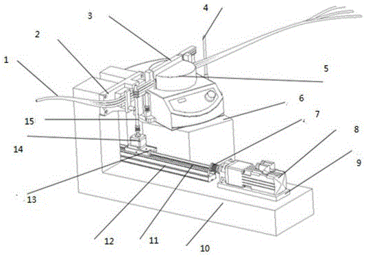
FIG. 1 is a schematic view of a general structure of a current limiting device;
FIG. 2 is a schematic view of the left side of the current limiting device;
FIG. 3 is a schematic diagram of the cam mechanism;
fig. 4 is a schematic view of the right side of the flow restriction device.
Detailed Description
As shown in the figure, the whole flow limiting device comprises a hose flow limiting module and a flow limiting execution module.
The mechanism of the current-limiting execution module is mainly placed at two ends of a peristaltic head groove of the peristaltic pump and is divided into three parts; a first part: the first limit block 17 is fixed on the front half part of a peristaltic head of the peristaltic pump, the first limit block 17 is matched with a first lead screw, three grooves matched with the hose in size are formed in the first limit block 17, the first lead screw is connected to a first stepping motor 22, and the first limit block 17 can move up and down under the driving of the first stepping motor 22; a second part: second stopper 20 passes through the stopper mount to be fixed at the latter half of wriggling head, also has three grooves identical with the hose size on the second stopper 20, and it is driven by second step motor 31 with the cooperation of second lead screw 30, can realize reciprocating of stopper, the third part: the bottom of the limiting rod 4 is fixed on a rotary rack block 32, the limiting block 21 is arranged at the head, the other end of the rotary rack block is matched with a gear on a motor 33, the rotation of the motor can drive the gear to rotate so as to drive a rack to move, the limiting rod can rotate on a special guide rail at the end face of a support 34, and the part of the peristaltic head is also provided with limiting blocks 18 and 19.
When the limiting executing module works, the limiting executing module starts to work when the manipulator of the needle grasping module pulls the hose 1 to the position of the peristaltic pump groove, firstly, the limiting rod rotates to limit the hose, then the hose moves downwards to the groove of the second limiting block 20 and the limiting groove 24 under the action of the needle grasping manipulator, then the hose and the limiting groove are driven by the motors 31 and 14 to move downwards to the bottom of the peristaltic pump groove along the peristaltic groove, the peristaltic pump is started, and the limiting rod returns to the initial position under the action of the motor 33.
The positions of three grooves on a hose flow limiting groove 24 in the hose flow limiting module and a peristaltic groove of a peristaltic pump 5 are on the same straight line, the peristaltic pump 5 is arranged on a peristaltic pump mounting seat 6, one section of the flow limiting groove 24 is connected with the peristaltic pump and then fixed on a support 10 of a flow limiting device, three cams 27, 28 and 29 which correspond to each other are arranged in the middle of the front of the three flow limiting grooves, the cams are matched with a third lead screw 15, and meanwhile, the third lead screw 15 can rotate under the driving of a third stepping motor 14. And a third step motor 14 is fixed on a sliding block 13, the sliding block is connected with a lead screw and is matched with a guide rail 12, the lead screw 11 is connected with a motor 8, the sliding block 13, the motor 14, the lead screw 15 and a cam can move back and forth along the guide rail through a coupler 7 under the drive of the motor 8, and the motor 8 is arranged on a motor support base plate 9. The hose fixing groove plate 23 is connected with a screw 25, and the limiting block can move back and forth under the driving of a motor 26.
In operation, the hose flow limiting module is operated after the hose is mounted on the module, and in the last operation, the hose is already located in the flow limiting groove, then the motor 26 is started, the flow limiting block moves towards the hose along the lead screw 25 until the hose is pressed, and the motor is stopped. Then the motor 8 drives the screw rod 11 to rotate, the slide block moves towards the direction of the hose flow limiting groove until the second cam and the third cam contact the hose, namely the third screw rods 15 and 16 enter the shaft groove of the flow limiting groove 24, and then the motor 22 rotates to drive the cams to rotate so as to realize the operation of sequentially conducting other two flow limiting on one of the three hoses.
To sum up, the current limiting device designed by the invention realizes that the culture medium is pumped into a specified culture bottle by driving the cam mechanism to open and close the hose through the motor, and comprises the following components: the flow-limiting device comprises a flow-limiting groove supporting plate 2, a flow-limiting pipe auxiliary mechanism 3, a hose fixing device, a cam group and a corresponding supporting mechanism, and any two of three parallel hoses are subjected to flow limiting through three coaxial cams. The design solves the problem that the position of the hose is difficult to determine, innovatively uses the cam to limit the flow of the hose, simplifies the whole flow limiting device and is convenient to operate.
Claims (1)
Priority Applications (1)
| Application Number | Priority Date | Filing Date | Title |
|---|---|---|---|
| CN201710171186.0A CN106744590B (en) | 2017-03-21 | 2017-03-21 | Current limiting device based on full-automatic sample subpackaging system |
Applications Claiming Priority (1)
| Application Number | Priority Date | Filing Date | Title |
|---|---|---|---|
| CN201710171186.0A CN106744590B (en) | 2017-03-21 | 2017-03-21 | Current limiting device based on full-automatic sample subpackaging system |
Publications (2)
| Publication Number | Publication Date |
|---|---|
| CN106744590A CN106744590A (en) | 2017-05-31 |
| CN106744590B true CN106744590B (en) | 2022-04-12 |
Family
ID=58966541
Family Applications (1)
| Application Number | Title | Priority Date | Filing Date |
|---|---|---|---|
| CN201710171186.0A Active CN106744590B (en) | 2017-03-21 | 2017-03-21 | Current limiting device based on full-automatic sample subpackaging system |
Country Status (1)
| Country | Link |
|---|---|
| CN (1) | CN106744590B (en) |
Family Cites Families (9)
| Publication number | Priority date | Publication date | Assignee | Title |
|---|---|---|---|---|
| AR244863A1 (en) * | 1989-09-07 | 1993-11-30 | Marcelo Alberto Hoegner | A multi-valve and the sterilising equipment that contains it. |
| DE19959473A1 (en) * | 1999-12-10 | 2001-06-13 | Frederic Dietrich | Device and method for the pneumatic conveying of powdery substances and use of the device |
| US6659142B2 (en) * | 2001-03-27 | 2003-12-09 | Irm, Llc | Apparatus and method for preparing fluid mixtures |
| DE602004009494T2 (en) * | 2003-05-13 | 2008-07-31 | Seiko Epson Corp. | Pipe valve, pipe valve device and head cleaning device |
| CN201420005Y (en) * | 2009-06-22 | 2010-03-10 | 东莞市百味佳食品有限公司 | Liquid canning machine |
| EP2743705B1 (en) * | 2010-07-23 | 2016-10-12 | Beckman Coulter, Inc. | System or method of including analytical units |
| US20150114515A1 (en) * | 2013-10-31 | 2015-04-30 | Oden Machinery Inc. | Liquid filler using single motive force |
| CN205330937U (en) * | 2016-01-27 | 2016-06-22 | 温州维科生物实验设备有限公司 | Tubular peristaltic pump is put to straight line |
| CN206607012U (en) * | 2017-03-21 | 2017-11-03 | 杭州电子科技大学 | A kind of current-limiting apparatus based on full-automatic sample sub-packaging system |
-
2017
- 2017-03-21 CN CN201710171186.0A patent/CN106744590B/en active Active
Also Published As
| Publication number | Publication date |
|---|---|
| CN106744590A (en) | 2017-05-31 |
Similar Documents
| Publication | Publication Date | Title |
|---|---|---|
| WO2021189883A1 (en) | Apparatus for continuously dispensing medicine from multiple medicine bottles and medicine dispensing method thereof | |
| CN106272368A (en) | A kind of the most quickly test tube stopper removing machine device people and take lid method | |
| CN205103269U (en) | Continuous injector | |
| CN113414562A (en) | Production line positioning device | |
| CN106771297B (en) | Automatic sample body-packing based on Sterility testing flow | |
| CN106744590B (en) | Current limiting device based on full-automatic sample subpackaging system | |
| CN116901465B (en) | A takeover machine | |
| CN202093004U (en) | Automatic ion chromatography sample introduction device | |
| CN206607012U (en) | A kind of current-limiting apparatus based on full-automatic sample sub-packaging system | |
| CN202583142U (en) | Pulse rotation type automatic sample injector | |
| CN206609889U (en) | A kind of full-automatic sample body-packing based on Sterility testing flow | |
| CN106041477B (en) | Mother needle base and catheter assembly device | |
| CN211970613U (en) | An automatic dispensing machine for pharmacy | |
| CN202975850U (en) | Micro-scale sample introduction control system | |
| CN214444343U (en) | Automatic horizontal steering device for three-way short pipe assembly | |
| CN219104450U (en) | Automatic sampling device of cell capturing staining instrument | |
| CN208171568U (en) | A lock fatigue test device | |
| CN112691260B (en) | A syringe installation device for hematology | |
| CN213168649U (en) | Liquid subpackaging device based on peristaltic pump | |
| CN112975328B (en) | Three-way short pipe assembly steering device and use method thereof | |
| CN209624189U (en) | A kind of pesticide residue automatic extracting instrument | |
| CN220600781U (en) | Isolator and pharmaceutical equipment's connection structure | |
| CN219162164U (en) | Emergency biochemical inspection device | |
| CN223340977U (en) | Multifunctional film sealing instrument | |
| CN212222390U (en) | A drip irrigation device based on biological agents |
Legal Events
| Date | Code | Title | Description |
|---|---|---|---|
| PB01 | Publication | ||
| PB01 | Publication | ||
| SE01 | Entry into force of request for substantive examination | ||
| SE01 | Entry into force of request for substantive examination | ||
| GR01 | Patent grant | ||
| GR01 | Patent grant |