CN202093004U - Automatic ion chromatography sample introduction device - Google Patents
Automatic ion chromatography sample introduction device Download PDFInfo
- Publication number
- CN202093004U CN202093004U CN2011201780854U CN201120178085U CN202093004U CN 202093004 U CN202093004 U CN 202093004U CN 2011201780854 U CN2011201780854 U CN 2011201780854U CN 201120178085 U CN201120178085 U CN 201120178085U CN 202093004 U CN202093004 U CN 202093004U
- Authority
- CN
- China
- Prior art keywords
- sample bottle
- stopple coupon
- sample
- sampling
- sampling tube
- Prior art date
- Legal status (The legal status is an assumption and is not a legal conclusion. Google has not performed a legal analysis and makes no representation as to the accuracy of the status listed.)
- Expired - Fee Related
Links
Images

Landscapes
- Automatic Analysis And Handling Materials Therefor (AREA)
Abstract
一种离子色谱的自动进样装置,样品瓶驱动动力驱动至少两个样品瓶在水平面上运动,取样管驱动动力驱动取样管作垂直运动,取样管连通取样泵,样品瓶和取样管的轴线平行;取样管在水平面上的投影落在工作位置上的样品瓶内;样品瓶驱动动力、取样管驱动动力和取样泵连接控制系统。本实用新型能够自动对两个或多个样品进样,进样效率高,性价比高,自动进样装置的部件国内能够生产,价格便宜,组装容易。
An automatic sampling device for ion chromatography, the driving power of the sample bottle drives at least two sample bottles to move on the horizontal plane, the driving power of the sampling tube drives the sampling tube to move vertically, the sampling tube is connected to the sampling pump, and the axes of the sample bottle and the sampling tube are parallel ; The projection of the sampling tube on the horizontal plane falls in the sample bottle on the working position; the driving power of the sample bottle, the driving power of the sampling tube and the sampling pump are connected to the control system. The utility model can automatically inject two or more samples, and has high sampling efficiency and high cost performance. The parts of the automatic sampling device can be produced domestically, and the price is cheap and the assembly is easy.
Description
技术领域 technical field
本实用新型涉及将溶液切入离子色谱流路的进样装置,具体地讲是一种离子色谱的自动进样装置。The utility model relates to a sampling device for cutting a solution into an ion chromatography flow path, in particular to an automatic sampling device for the ion chromatography.
背景技术 Background technique
由于技术上的原因,目前国内生产的离子色谱仪器普遍使用进口的手动进样阀。手动进样阀受控制方法的限制和制约,只能单次间断作业,每一样品测试时需先手动将阀置于进样控制位置,向离子色谱注入待测样品溶液,然后再手动将阀置于分析控制位置。手动进样占用人工,功效低,难以实现自动检测。此外,进口手动进样阀还存在价格高、供货周期长的问题。Due to technical reasons, currently domestically produced ion chromatography instruments generally use imported manual injection valves. The manual injection valve is limited and restricted by the control method, and it can only work intermittently once. When testing each sample, it is necessary to manually place the valve at the injection control position, inject the sample solution to be tested into the ion chromatograph, and then manually open the valve. Placed in analytical control position. Manual sample injection takes manpower, has low efficiency, and is difficult to realize automatic detection. In addition, the imported manual injection valve still has the problems of high price and long delivery cycle.
实用新型内容 Utility model content
本实用新型要解决现有手动进样阀单次间断作业,占用人工操作,功效低;进口手动进样阀价格高、供货周期长的技术问题,提供一种能够自动对两个以上样品进样,进样效率高,性价比高的国产离子色谱的自动进样装置。The utility model aims to solve the technical problems of the single intermittent operation of the existing manual sampling valve, which takes up manual operation and has low efficacy; the imported manual sampling valve is expensive and has a long supply cycle, and provides a device that can automatically inject more than two samples. Sample, high injection efficiency, cost-effective domestic ion chromatography automatic sampling device.
为了解决上述技术问题,本实用新型采取的技术方案是:一种离子色谱的自动进样装置,包括样品瓶,样品瓶驱动动力驱动至少两个样品瓶在水平面上运动,取样管驱动动力驱动取样管作垂直运动,取样管连通取样泵,样品瓶和取样管的轴线平行;取样管在水平面上的投影落在工作位置上的样品瓶内;样品瓶驱动动力、取样管驱动动力和取样泵连接控制系统。In order to solve the above technical problems, the technical solution adopted by the utility model is: an automatic sampling device for ion chromatography, including a sample bottle, the driving power of the sample bottle drives at least two sample bottles to move on the horizontal plane, and the driving power of the sampling tube drives the sampling The tube moves vertically, the sampling tube is connected to the sampling pump, and the axes of the sample bottle and the sampling tube are parallel; the projection of the sampling tube on the horizontal plane falls into the sample bottle at the working position; the driving power of the sample bottle, the driving power of the sampling tube and the sampling pump are connected Control System.
在控制系统控制下,样品瓶驱动动力、取样管驱动动力和取样泵协调动作,完成自动进样。样品瓶驱动动力驱动样品瓶依次停于工作位置。在取样管驱动动力驱动下,取样管伸入停于工作位置的一个样品瓶的液体中,由取样泵将液体经由取样管输送到离子色谱的检测流路中;取样管驱动动力驱动取样管升起,脱离样品瓶;在样品瓶驱动动力驱动下,另一个样品瓶停于工作位置,取样管驱动动力驱动取样管伸入另一个样品瓶的液体中,由取样泵将液体经由取样管输送到离子色谱的检测流路中,如此,实现自动进样。本实用新型能够自动对两个或多个样品进样,进样效率高,性价比高,自动进样装置的部件国内能够生产,价格便宜,组装容易。有诸多现有技术能够实现样品瓶驱动动力驱动样品瓶运动,比如样品瓶驱动动力电机,通过其主轴上的齿轮与支持样品瓶的托架上的齿条啮合,驱使样品瓶在水平面上往返运动;又如样品瓶驱动动力电机,通过其主轴上的齿轮与支持样品瓶的托架中心轴上的齿轮啮合,驱使样品瓶在水平面上作圆周运动等等。有诸多现有技术能够实现取样管驱动动力驱动取样管运动,比如取样管驱动动力电机,通过其水平主轴上的齿轮与固定连接取样管支架上的垂直齿条啮合,驱使取样管在垂直方向运动;又如取样管驱动动力电机驱动链轮旋转,取样管固定在与链轮啮合的链条上,取样管驱动动力电机驱使取样管在垂直方向运动等等。Under the control of the control system, the driving power of the sample bottle, the driving power of the sampling tube and the sampling pump cooperate to complete automatic sampling. The sample bottle driving power drives the sample bottle to stop at the working position in sequence. Driven by the driving power of the sampling tube, the sampling tube extends into the liquid in a sample bottle stopped at the working position, and the liquid is transported by the sampling pump to the detection flow path of the ion chromatography through the sampling tube; the driving power of the sampling tube drives the sampling tube to rise Driven by the driving power of the sample bottle, the other sample bottle stops at the working position, the driving power of the sampling tube drives the sampling tube to extend into the liquid of the other sample bottle, and the liquid is transported by the sampling pump to the In the detection flow path of ion chromatography, in this way, automatic sampling is realized. The utility model can automatically inject two or more samples, and has high sampling efficiency and high cost performance. The parts of the automatic sampling device can be produced domestically, and the price is cheap and the assembly is easy. There are many existing technologies that can realize the movement of the sample vial driving power, such as the sample vial driving power motor, through the gear on the main shaft meshing with the rack on the bracket supporting the sample vial, driving the vial to move back and forth on the horizontal plane ; Another example is the sample bottle driving power motor, through which the gear on the main shaft meshes with the gear on the central axis of the bracket supporting the sample bottle, driving the sample bottle to make a circular motion on the horizontal plane and so on. There are many existing technologies that can realize the sampling tube driving power to drive the sampling tube to move. For example, the sampling tube drives the power motor, and the gear on the horizontal spindle meshes with the vertical rack fixedly connected to the sampling tube bracket to drive the sampling tube to move in the vertical direction. ; Another example is that the sampling tube drives the power motor to drive the sprocket to rotate, the sampling tube is fixed on the chain meshed with the sprocket, and the sampling tube drives the power motor to drive the sampling tube to move in the vertical direction and so on.
样品瓶放置在由上层托盘和下层托盘组成的托架上,样品瓶驱动动力是样品瓶驱动步进电机,样品瓶驱动步进电机输出轴与托架中心轴同心固定连接。样品瓶驱动步进电机驱动样品瓶在水平面上作圆周运动。The sample bottle is placed on the bracket consisting of the upper tray and the lower tray. The driving power of the sample bottle is the sample bottle driving stepping motor, and the output shaft of the sample bottle driving stepping motor is concentrically fixedly connected with the central axis of the bracket. The sample bottle is driven by a stepper motor to drive the sample bottle to make a circular motion on the horizontal plane.
取样管的后端固定连接取样管支架,取样管驱动动力是取样管驱动步进电机,取样管驱动步进电机固定在自动进样装置底座上,取样管驱动步进电机的输出轴连接丝杆,丝杆与取样管支架上的丝母配合。取样管驱动步进电机驱动取样管作垂直运动。The rear end of the sampling tube is fixedly connected to the sampling tube bracket. The driving power of the sampling tube is the sampling tube driving stepping motor. The sampling tube driving stepping motor is fixed on the base of the automatic sampling device. The output shaft of the sampling tube driving the stepping motor is connected to the screw. , the screw mandrel cooperates with the screw nut on the sampling tube bracket. The sampling tube drives the stepper motor to drive the sampling tube to move vertically.
样品瓶有偶数个,样品瓶分别盛放待测样品溶液和淋洗液,盛放待测样品溶液的样品瓶和盛放淋洗液的样品瓶相间排布。取样管交替地伸入盛放待测样品溶液的样品瓶和盛放淋洗液的样品瓶,沾染了待测样品溶液的取样管,经过淋洗液进行清洗,避免了待测样品之间产生影响。There are an even number of sample bottles, and the sample bottles hold the sample solution to be tested and the eluent respectively, and the sample bottles for the sample solution to be tested and the sample bottles for the eluent are arranged alternately. The sampling tubes alternately extend into the sample bottle containing the sample solution to be tested and the sample bottle containing the eluent, and the sampling tube that is contaminated with the sample solution to be tested is cleaned by the eluent to avoid the occurrence of contamination between the samples to be tested. Influence.
取样管是呈空心针状的吸针。吸针类似注射针头,样品瓶内的液体从吸针的空心腔被吸出。The sampling tube is a suction needle in the shape of a hollow needle. The aspiration needle is similar to an injection needle, and the liquid in the sample bottle is sucked out from the hollow cavity of the aspiration needle.
样品瓶盛放待测样品溶液后,其上口覆盖封口膜。封口膜用于防尘和避免样品被空气氧化,取样管刺破封口膜伸入样品瓶的液体中。After the sample bottle is filled with the sample solution to be tested, its upper opening is covered with a parafilm. The sealing film is used to prevent dust and prevent the sample from being oxidized by air, and the sampling tube pierces the sealing film and extends into the liquid in the sample bottle.
盛放淋洗液的样品瓶内液面高于盛放待测样品溶液的样品瓶内液面。以保证每个盛放淋洗液的样品瓶都能真实有效的将取样管进行外表面的清洗工作,以避免污染样品的情况发生。The liquid level in the sample bottle containing the eluent is higher than the liquid level in the sample bottle containing the sample solution to be tested. To ensure that each sample bottle containing the eluent can effectively clean the outer surface of the sampling tube to avoid contamination of the sample.
本实用新型的优点是:本实用新型能够自动对两个或多个样品进样,进样效率高,性价比高,自动进样装置的部件国内能够生产,价格便宜,组装容易。The utility model has the advantages that: the utility model can automatically inject two or more samples, has high sampling efficiency and high cost performance, and the parts of the automatic sampling device can be produced domestically, with low price and easy assembly.
附图说明 Description of drawings
图1是本实用新型一个实施例的结构示意图;Fig. 1 is the structural representation of an embodiment of the utility model;
图2是图1的俯视图。FIG. 2 is a top view of FIG. 1 .
具体实施方式 Detailed ways
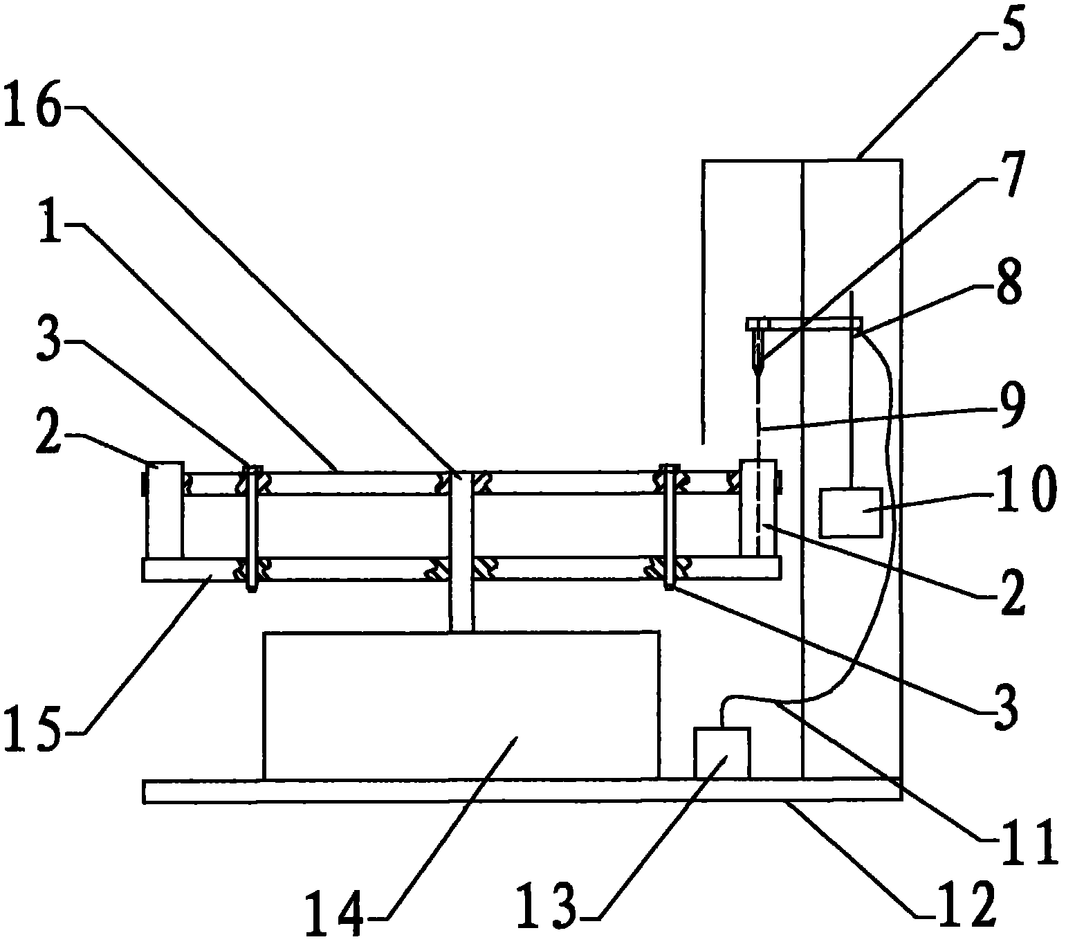
结合附图说明。为了显示的清楚,图1中将滑台外壳5前面去掉,放置样品瓶2托架的上层托盘1和下层托盘15局部采取剖视。Description with reference to the accompanying drawings. In order to show clearly, in Fig. 1, the front side of the
本实施例的40个上部为圆柱形,下部为锥形的样品瓶2均匀放置在圆形上层托盘1外缘处的40个通孔中,精制铝合金材质的上层托盘1和下层托盘15直径相同,与上层托盘1通孔圆心相对位置的下层托盘15上有锥形孔,用于对样品瓶下端的锥形定位。固定螺钉3将上层托盘1和下层托盘15间隔和同心紧固连接组成样品瓶2的放置托架。样品瓶驱动动力是每个脉冲步距角0.9度,DC+24V/2A的三相四拍制样品瓶驱动步进电机14,样品瓶驱动步进电机输出轴与托架中心轴16同心固定连接,样品瓶驱动步进电机14驱动样品瓶2在水平面上作圆周运动。本实施例的取样管是不锈钢材质的呈空心针状的吸针7,吸针7的后端固定连接取样管支架,取样管驱动动力是每个脉冲步距角0.9度,DC+24V/2A的三相四拍制取样管驱动步进电机10,取样管驱动步进电机10固定在滑台外壳5上,其垂直输出轴连接高精度丝杆8,丝杆8与取样管支架上的丝母配合,取样管驱动步进电机10驱动吸针7沿吸针运动轨迹9上下运动,图中没有显示丝母。塑料材质的滑台外壳5遮挡离子色谱自动进样装置外部空间的尘土及其他杂质进入滑台内部。样品瓶2分别盛放待测样品溶液和淋洗液,为避免高浓度的样品做完检测之后,污染低浓度的待测样品,盛放待测样品溶液的样品瓶2和盛放淋洗液的样品瓶2相间排布,盛放淋洗液的样品瓶内液面高于盛放待测样品溶液的样品瓶内液面。样品瓶2盛放待测样品溶液后,其上口覆盖着封口膜。样品瓶驱动步进电机14驱动样品瓶2绕中心轴16每次旋转9度,40个样品瓶2依次停于工作位置,吸针7连通取样泵,本实施例的取样泵是蠕动泵13,管路11连接蠕动泵13与吸针7。样品瓶2和吸针7的轴线平行;吸针7在水平面上的投影落在工作位置的样品瓶2内。样品瓶驱动步进电机14、蠕动泵13、滑台外壳5固定安装在自动进样装置底座12上。样品瓶驱动动力、取样管驱动动力和取样泵连接控制系统,在控制系统控制下,样品瓶驱动动力、取样管驱动动力和取样泵协调动作,完成自动进样。The 40 tops of the present embodiment are cylindrical and the bottoms are tapered
本实施例工作流程如下:接通电源后,吸针7在取样管驱动步进电机10的带动下,升至丝杆8的中上部;样品瓶驱动步进电机14在控制板的控制下带动样品瓶2随放置托架回到起始位置处;之后,取样管驱动步进电机10控制吸针7下降至第一个样品瓶2内,开启蠕动泵13吸取待测样品溶液,进样完毕后,关闭蠕动泵13;控制取样管驱动步进电机10升起吸针7回到丝杆8的中上部。随之,离子色谱仪开始对待测样品进行检测分析。当待测样品的检测分析完成后,控制样品瓶驱动步进电机14旋转,下一个样品瓶2至吸针运动轨迹9的轨迹线上,将吸针7落在样品瓶2内,开启蠕动泵7吸取淋洗液,对吸针7的外表面及整个进样管路进行冲洗。冲洗完毕后,关闭蠕动泵7,控制取样管驱动步进电机10将吸针7再次抬起至丝杆8的中上部。如此反复进行,直至将所有样品全部检测和分析完毕,离子色谱自动进样装置重新回至起点位置处。至此,所有的样品进样和管路清洗流程全部结束。The working process of this embodiment is as follows: after the power is turned on, the suction needle 7 is driven to the middle and upper part of the
Claims (7)
Priority Applications (1)
| Application Number | Priority Date | Filing Date | Title |
|---|---|---|---|
| CN2011201780854U CN202093004U (en) | 2011-05-18 | 2011-05-18 | Automatic ion chromatography sample introduction device |
Applications Claiming Priority (1)
| Application Number | Priority Date | Filing Date | Title |
|---|---|---|---|
| CN2011201780854U CN202093004U (en) | 2011-05-18 | 2011-05-18 | Automatic ion chromatography sample introduction device |
Publications (1)
| Publication Number | Publication Date |
|---|---|
| CN202093004U true CN202093004U (en) | 2011-12-28 |
Family
ID=45368064
Family Applications (1)
| Application Number | Title | Priority Date | Filing Date |
|---|---|---|---|
| CN2011201780854U Expired - Fee Related CN202093004U (en) | 2011-05-18 | 2011-05-18 | Automatic ion chromatography sample introduction device |
Country Status (1)
| Country | Link |
|---|---|
| CN (1) | CN202093004U (en) |
Cited By (5)
| Publication number | Priority date | Publication date | Assignee | Title |
|---|---|---|---|---|
| CN103616358A (en) * | 2013-11-30 | 2014-03-05 | 广州蓝勃生物科技有限公司 | Environment-friendly multi-project full-automatic solid phase fluorescence detection system |
| CN110749685A (en) * | 2019-09-11 | 2020-02-04 | 青岛盛瀚色谱技术有限公司 | A kind of automatic sampler and needle washing method |
| CN114207434A (en) * | 2019-07-29 | 2022-03-18 | 沃特世科技公司 | Method of loading a sample into a sample manager of a chromatography system |
| CN114236161A (en) * | 2021-12-31 | 2022-03-25 | 南京国科医工科技发展有限公司 | Liquid suction structure and liquid supply device for immunoassay |
| CN114324925A (en) * | 2021-12-16 | 2022-04-12 | 浙江西热利华智能传感技术有限公司 | Automatic sampling and sample introduction instrument for water sample detection and sampling and sample introduction method |
-
2011
- 2011-05-18 CN CN2011201780854U patent/CN202093004U/en not_active Expired - Fee Related
Cited By (5)
| Publication number | Priority date | Publication date | Assignee | Title |
|---|---|---|---|---|
| CN103616358A (en) * | 2013-11-30 | 2014-03-05 | 广州蓝勃生物科技有限公司 | Environment-friendly multi-project full-automatic solid phase fluorescence detection system |
| CN114207434A (en) * | 2019-07-29 | 2022-03-18 | 沃特世科技公司 | Method of loading a sample into a sample manager of a chromatography system |
| CN110749685A (en) * | 2019-09-11 | 2020-02-04 | 青岛盛瀚色谱技术有限公司 | A kind of automatic sampler and needle washing method |
| CN114324925A (en) * | 2021-12-16 | 2022-04-12 | 浙江西热利华智能传感技术有限公司 | Automatic sampling and sample introduction instrument for water sample detection and sampling and sample introduction method |
| CN114236161A (en) * | 2021-12-31 | 2022-03-25 | 南京国科医工科技发展有限公司 | Liquid suction structure and liquid supply device for immunoassay |
Similar Documents
| Publication | Publication Date | Title |
|---|---|---|
| CN202093004U (en) | Automatic ion chromatography sample introduction device | |
| CN201497691U (en) | Automatic detecting device for closed blood viscosity measurement | |
| CN116086905B (en) | Tubular mass spectrum pretreatment instrument | |
| CN101603968A (en) | The closed automatic detection device of blood rheology measurement | |
| CN101982779B (en) | Automatic sampling mechanism of analytical instrument | |
| CN204479388U (en) | A kind of urine filtering device | |
| CN210964039U (en) | A fully automatic solid-phase extraction device for radiochemistry | |
| CN107831040A (en) | A kind of fluid sample sampler | |
| CN202066843U (en) | Ion chromatographic sampling device | |
| CN108318291A (en) | Automatic sampling mechanism for hospital laboratory blood analysis instrument | |
| CN104062457B (en) | A kind of automatic sampling apparatus detected for water chemical oxygen demand | |
| CN102632046A (en) | Improved environmental-friendly high-efficiency fully automatic plate washing machine movement device | |
| CN105259355A (en) | Automatic biological sample pretreatment device | |
| CN109917147B (en) | A kind of automatic sampling device and method | |
| CN115436107A (en) | A sampling device for dairy product testing | |
| CN106442026B (en) | Seven-station sampling rotary table type heavy metal enrichment sampling and pretreatment system based on nano functional material | |
| CN204964275U (en) | Automatic metaplasia thing sample pretreatment device | |
| CN105424950B (en) | An automatic detection device for rock wool nutrient solution in agricultural greenhouses | |
| CN204008679U (en) | The automatic sampler that comprises test tube integral sealing means | |
| CN202562934U (en) | Full-automatic hemorrheology sample introduction system | |
| CN217450231U (en) | Automatic liquid transfer device for laboratory | |
| CN210269883U (en) | A multifunctional multi-channel sampling device for permanganate index analyzer | |
| CN203838060U (en) | Automatic device for detecting and enriching heavy metals by virtue of portable raman spectrometer | |
| CN210665239U (en) | Automatic nitrogen blowing instrument | |
| CN209432742U (en) | Seawater trace element automatic separation and enrichment system |
Legal Events
| Date | Code | Title | Description |
|---|---|---|---|
| C14 | Grant of patent or utility model | ||
| GR01 | Patent grant | ||
| CF01 | Termination of patent right due to non-payment of annual fee | ||
| CF01 | Termination of patent right due to non-payment of annual fee |
Granted publication date: 20111228 Termination date: 20200518 |