CN103415365A - Process for local repair of a damaged thermomechanical part and part thus produced, in particular a turbine part - Google Patents
Process for local repair of a damaged thermomechanical part and part thus produced, in particular a turbine part Download PDFInfo
- Publication number
- CN103415365A CN103415365A CN2012800119749A CN201280011974A CN103415365A CN 103415365 A CN103415365 A CN 103415365A CN 2012800119749 A CN2012800119749 A CN 2012800119749A CN 201280011974 A CN201280011974 A CN 201280011974A CN 103415365 A CN103415365 A CN 103415365A
- Authority
- CN
- China
- Prior art keywords
- parts
- temperature
- superalloy
- sintering
- repaired
- Prior art date
- Legal status (The legal status is an assumption and is not a legal conclusion. Google has not performed a legal analysis and makes no representation as to the accuracy of the status listed.)
- Granted
Links
Images


Classifications
-
- B—PERFORMING OPERATIONS; TRANSPORTING
- B22—CASTING; POWDER METALLURGY
- B22F—WORKING METALLIC POWDER; MANUFACTURE OF ARTICLES FROM METALLIC POWDER; MAKING METALLIC POWDER; APPARATUS OR DEVICES SPECIALLY ADAPTED FOR METALLIC POWDER
- B22F7/00—Manufacture of composite layers, workpieces, or articles, comprising metallic powder, by sintering the powder, with or without compacting wherein at least one part is obtained by sintering or compression
- B22F7/02—Manufacture of composite layers, workpieces, or articles, comprising metallic powder, by sintering the powder, with or without compacting wherein at least one part is obtained by sintering or compression of composite layers
- B22F7/04—Manufacture of composite layers, workpieces, or articles, comprising metallic powder, by sintering the powder, with or without compacting wherein at least one part is obtained by sintering or compression of composite layers with one or more layers not made from powder, e.g. made from solid metal
-
- B—PERFORMING OPERATIONS; TRANSPORTING
- B22—CASTING; POWDER METALLURGY
- B22F—WORKING METALLIC POWDER; MANUFACTURE OF ARTICLES FROM METALLIC POWDER; MAKING METALLIC POWDER; APPARATUS OR DEVICES SPECIALLY ADAPTED FOR METALLIC POWDER
- B22F3/00—Manufacture of workpieces or articles from metallic powder characterised by the manner of compacting or sintering; Apparatus specially adapted therefor ; Presses and furnaces
- B22F3/10—Sintering only
- B22F3/105—Sintering only by using electric current other than for infrared radiant energy, laser radiation or plasma ; by ultrasonic bonding
-
- B—PERFORMING OPERATIONS; TRANSPORTING
- B22—CASTING; POWDER METALLURGY
- B22F—WORKING METALLIC POWDER; MANUFACTURE OF ARTICLES FROM METALLIC POWDER; MAKING METALLIC POWDER; APPARATUS OR DEVICES SPECIALLY ADAPTED FOR METALLIC POWDER
- B22F5/00—Manufacture of workpieces or articles from metallic powder characterised by the special shape of the product
- B22F5/009—Manufacture of workpieces or articles from metallic powder characterised by the special shape of the product of turbine components other than turbine blades
-
- B—PERFORMING OPERATIONS; TRANSPORTING
- B22—CASTING; POWDER METALLURGY
- B22F—WORKING METALLIC POWDER; MANUFACTURE OF ARTICLES FROM METALLIC POWDER; MAKING METALLIC POWDER; APPARATUS OR DEVICES SPECIALLY ADAPTED FOR METALLIC POWDER
- B22F5/00—Manufacture of workpieces or articles from metallic powder characterised by the special shape of the product
- B22F5/04—Manufacture of workpieces or articles from metallic powder characterised by the special shape of the product of turbine blades
-
- B—PERFORMING OPERATIONS; TRANSPORTING
- B22—CASTING; POWDER METALLURGY
- B22F—WORKING METALLIC POWDER; MANUFACTURE OF ARTICLES FROM METALLIC POWDER; MAKING METALLIC POWDER; APPARATUS OR DEVICES SPECIALLY ADAPTED FOR METALLIC POWDER
- B22F7/00—Manufacture of composite layers, workpieces, or articles, comprising metallic powder, by sintering the powder, with or without compacting wherein at least one part is obtained by sintering or compression
- B22F7/06—Manufacture of composite layers, workpieces, or articles, comprising metallic powder, by sintering the powder, with or without compacting wherein at least one part is obtained by sintering or compression of composite workpieces or articles from parts, e.g. to form tipped tools
- B22F7/062—Manufacture of composite layers, workpieces, or articles, comprising metallic powder, by sintering the powder, with or without compacting wherein at least one part is obtained by sintering or compression of composite workpieces or articles from parts, e.g. to form tipped tools involving the connection or repairing of preformed parts
- B22F7/064—Manufacture of composite layers, workpieces, or articles, comprising metallic powder, by sintering the powder, with or without compacting wherein at least one part is obtained by sintering or compression of composite workpieces or articles from parts, e.g. to form tipped tools involving the connection or repairing of preformed parts using an intermediate powder layer
-
- B—PERFORMING OPERATIONS; TRANSPORTING
- B22—CASTING; POWDER METALLURGY
- B22F—WORKING METALLIC POWDER; MANUFACTURE OF ARTICLES FROM METALLIC POWDER; MAKING METALLIC POWDER; APPARATUS OR DEVICES SPECIALLY ADAPTED FOR METALLIC POWDER
- B22F7/00—Manufacture of composite layers, workpieces, or articles, comprising metallic powder, by sintering the powder, with or without compacting wherein at least one part is obtained by sintering or compression
- B22F7/06—Manufacture of composite layers, workpieces, or articles, comprising metallic powder, by sintering the powder, with or without compacting wherein at least one part is obtained by sintering or compression of composite workpieces or articles from parts, e.g. to form tipped tools
- B22F7/08—Manufacture of composite layers, workpieces, or articles, comprising metallic powder, by sintering the powder, with or without compacting wherein at least one part is obtained by sintering or compression of composite workpieces or articles from parts, e.g. to form tipped tools with one or more parts not made from powder
-
- B—PERFORMING OPERATIONS; TRANSPORTING
- B23—MACHINE TOOLS; METAL-WORKING NOT OTHERWISE PROVIDED FOR
- B23P—METAL-WORKING NOT OTHERWISE PROVIDED FOR; COMBINED OPERATIONS; UNIVERSAL MACHINE TOOLS
- B23P6/00—Restoring or reconditioning objects
- B23P6/002—Repairing turbine components, e.g. moving or stationary blades, rotors
- B23P6/007—Repairing turbine components, e.g. moving or stationary blades, rotors using only additive methods, e.g. build-up welding
-
- B—PERFORMING OPERATIONS; TRANSPORTING
- B22—CASTING; POWDER METALLURGY
- B22F—WORKING METALLIC POWDER; MANUFACTURE OF ARTICLES FROM METALLIC POWDER; MAKING METALLIC POWDER; APPARATUS OR DEVICES SPECIALLY ADAPTED FOR METALLIC POWDER
- B22F3/00—Manufacture of workpieces or articles from metallic powder characterised by the manner of compacting or sintering; Apparatus specially adapted therefor ; Presses and furnaces
- B22F3/10—Sintering only
- B22F3/105—Sintering only by using electric current other than for infrared radiant energy, laser radiation or plasma ; by ultrasonic bonding
- B22F2003/1051—Sintering only by using electric current other than for infrared radiant energy, laser radiation or plasma ; by ultrasonic bonding by electric discharge
-
- B—PERFORMING OPERATIONS; TRANSPORTING
- B22—CASTING; POWDER METALLURGY
- B22F—WORKING METALLIC POWDER; MANUFACTURE OF ARTICLES FROM METALLIC POWDER; MAKING METALLIC POWDER; APPARATUS OR DEVICES SPECIALLY ADAPTED FOR METALLIC POWDER
- B22F2999/00—Aspects linked to processes or compositions used in powder metallurgy
-
- Y—GENERAL TAGGING OF NEW TECHNOLOGICAL DEVELOPMENTS; GENERAL TAGGING OF CROSS-SECTIONAL TECHNOLOGIES SPANNING OVER SEVERAL SECTIONS OF THE IPC; TECHNICAL SUBJECTS COVERED BY FORMER USPC CROSS-REFERENCE ART COLLECTIONS [XRACs] AND DIGESTS
- Y10—TECHNICAL SUBJECTS COVERED BY FORMER USPC
- Y10T—TECHNICAL SUBJECTS COVERED BY FORMER US CLASSIFICATION
- Y10T29/00—Metal working
- Y10T29/49—Method of mechanical manufacture
- Y10T29/49316—Impeller making
- Y10T29/49318—Repairing or disassembling
-
- Y—GENERAL TAGGING OF NEW TECHNOLOGICAL DEVELOPMENTS; GENERAL TAGGING OF CROSS-SECTIONAL TECHNOLOGIES SPANNING OVER SEVERAL SECTIONS OF THE IPC; TECHNICAL SUBJECTS COVERED BY FORMER USPC CROSS-REFERENCE ART COLLECTIONS [XRACs] AND DIGESTS
- Y10—TECHNICAL SUBJECTS COVERED BY FORMER USPC
- Y10T—TECHNICAL SUBJECTS COVERED BY FORMER US CLASSIFICATION
- Y10T428/00—Stock material or miscellaneous articles
- Y10T428/12—All metal or with adjacent metals
- Y10T428/12014—All metal or with adjacent metals having metal particles
- Y10T428/12021—All metal or with adjacent metals having metal particles having composition or density gradient or differential porosity
Landscapes
- Engineering & Computer Science (AREA)
- Mechanical Engineering (AREA)
- Manufacturing & Machinery (AREA)
- Chemical & Material Sciences (AREA)
- Composite Materials (AREA)
- Materials Engineering (AREA)
- Physics & Mathematics (AREA)
- Optics & Photonics (AREA)
- Powder Metallurgy (AREA)
- Turbine Rotor Nozzle Sealing (AREA)
- Pressure Welding/Diffusion-Bonding (AREA)
Abstract
The present invention aims to mitigate the drawbacks of the prior art by enabling simple, rapid and effective production of precise 3-dimensional (3D) sinters in a shape substantially resembling that of an original part. To do this, the invention employs flash sintering produced using spark plasma sintering (SPS) technology. According to one embodiment, a mould (1) is produced in an SPS chamber die (11), the shape of the mould (1) being an imprint of the original part. The following layers are deposited in succession in the mould (1): a layer (31) based on a superalloy powder; a metallic protective layer (32); and a thermal barrier layer (33). In a sintering step, pressure is applied and a pulsed current causes a rapid increase in the temperature in a flash sintering cycle regulated in temperature, pressure and duration, with at least one temperature plateau and one pressure plateau. The superalloy layer (31) forms, by diffusing, during the sintering step, a material continuum anchored to the part (2) to be repaired.
Description
Technical field
The present invention relates to a kind ofly for part, repair and to have born during use strong stress for example burn into corrodes or the method for the heat engine tool parts of the damage of wearing and tearing.It also relates to the parts of manufacturing according to the method, and more specifically but not exclusively be applied to turbine components.
The field of the invention is the refractory material in nickel based super alloy.These materials can form heat engine tool parts, gas turbine parts in field of aerospace especially, for example mobile straightener(stator) blade or splitterr vanes, their platform, matrix or other devices, especially corrosion-resistant and sludge proof.
Yet these parts bear pressure and temperature stress so that material runs off, it need to be repaired by adding material.This reparation comprises that the original dimension that makes these parts turn back to it keeps the composition material of same type or chemical analogue compounds simultaneously.
Background technology
For this reason, when reparation is limited on the non-key and degree of parts limitedly when regional, knownly by arc welding, realize local the reparation.
For more greatly or more crucial reparation, a solution is included in the material that solid form is added in zone to be repaired.Described material then can from as by the preform of thin plate or batten cutting, obtained, described thin plate or batten rise to high-temperature by the mixture of superalloy powder and hard solder powder and make in specially suitable stove.Then this mixture is sintered, because what produced by this mixture of powders is the low melting point eutectic mixture.Then along zone to be repaired, that be cleaned, place the sinter obtained by this way, and the whole temperature that risen to.Then the diffusion brazing method occurs, and sinter is brazed on the surface of parts.
In the method, utilize water to spray to cut sintered sheets to produce planar (2D) preform.After solder brazing, formalize parts so that therefore the geometry of recovering it, near original geometry, and gives appropriate air dynamic behaviour by the ground flat zone.
The method comprises the existence of solder brazing powder, and the existence of the fusing composition therefore distributed on the whole thickness of sinter.Yet the existence of fusing composition has negative effect to thermomechanical property.
In addition, it only allows to produce two-dimentional sinter preform, has constant thickness, irrelevant with the zone of sinter.Yet in the recent release of the parts of paying close attention to, the sinter with vicissitudinous thickness of tool in some zone is favourable.Current method does not allow this precision.
In addition, via the generation of a plurality of consecutive steps generation sinters, must not comprise irrespective manufacturing cost.In addition, most of material runs off, and sinter is from the sheet production of the larger parts thrown away.
Summary of the invention
Target of the present invention is to improve the defect of prior art, and it provides the production of a kind of accurate three-dimensional simply, fast and effectively (3D) sinter, and the shape of this sinter is basically similar to the shape of primitive part.For this reason, the present invention uses flash (flash) sinter of being produced by discharge plasma sintering (SPS) technology.
The SPS technology, simultaneously in conjunction with the application of high uniaxial compression and the pulse of high strength direct current, causes temperature almost moment rising equably.This technology is known in the powder metallurgy field, and it makes it possible to from powder production metal parts or metal oxide via sintering and compression.Particularly, the use of SPS flash (flash) technology make it possible to manufacture have can controlled special micro-structure parts.
More specifically, the object of the invention is to a kind of method of repairing the heat engine tool parts of being manufactured by superalloy be used to having part.The method is included in for the mould of the shell of SPS flash sintering (enclosure) and produces a module in preparation process, described module is shaped to the die (imprint) of the reparation part at least of damaging parts, introduces one deck solder brazing powder and the powder based on superalloy of one deck formation multilayer integral (whole) at least at least in described module.Then, in sintering step, the fast rise of passing through to cause temperature in the circulation of flash sintering of supercharging and initiation pulse current, thereby can be by diffuseing to form the adhesive between material and parts, temperature, pressure and the duration of described flash sintering circulation are conditioned, and make it have at least one temperature stage of stable development and a pressure stage of stable development.This sintering step produces the preform with component gradient of multilayer integral form, and it has the solder brazing face that can be bonded to parts to be repaired, and superalloy material (6s) is presented on the surface of this preform.
Advantageously, regulate temperature, pressure and the duration of flash sintering circulation, make its temperature increase and be at least 600 ℃/minute, greatly the temperature stage of stable development in scope and the large pressure stage of stable development between 10Mpa and 100Mpa between 1000 ℃ and 2000 ℃.
According to an embodiment, described module has the shape corresponding to the die of whole primitive part.During sintering step, the superalloy layer forms the bonding continuum by being diffused between material and parts to be repaired.
In follow-up solder brazing step, the solder brazing face of the preform of making by this way can be placed as with the zone of parts to be repaired and contact.Then, by heating preform in appropriate stove and the temperature along the parts of its placement to the fusion temperature that equals at least hard soldering alloys, solder brazing face passes through the diffusion bonding of fusing element of hard soldering alloys in parts to be repaired.Therefore reduce significantly or even eliminate the machinery of parts in restoring area and weaken.
In follow-up solder brazing step, the solder brazing face of the preform of making by this way is placed as with the zone of parts to be repaired and contacts.Then, by heating preform in appropriate stove and the temperature along the parts of its placement to the fusion temperature that equals at least hard soldering alloys, solder brazing face passes through the diffusion bonding of fusing element of hard soldering alloys in parts to be repaired.
In concrete embodiment:
-during the preparatory stage, coat of metal and thermal insulation layer are deposited on the layer of superalloy;
-coat of metal comprises the mould that a slice at least is comprised of Ni, Pt, Hf, Y, Zr, Al, Si, Cu, Ag and/or Au, and/or by Ni-Al, the mould that Ni-Pt-Al and/or Ni-Al-Zr compound form;
-thermal insulation layer comprises yttria-stabilized zirconia (the heat insulation compound ZrO of 6-8 % by weight
2– 6-8Y
2O
3).
The invention still further relates to according to said method via the reparation of flash sintering, heat engine tool parts, especially turbine components that made by superalloy.Then described parts pass through the diffusion bonding of material to parts to be repaired.
The accompanying drawing explanation
With reference to accompanying drawing, read following description and this description and relate to an embodiment, it is clear that other features and advantages of the present invention will become, wherein:
Fig. 1 is illustrated in the cross sectional representation of example of the assembly of each layer in the SPS die module that is shaped to the die corresponding with primitive part;
Fig. 2 is illustrated in the flash sintering schematic partial cross-sectional view of same components afterwards;
Fig. 3 is illustrated in the cross sectional representation of example of the assembly of each layer in the SPS die module that is shaped to the die corresponding with a parts to be repaired part;
Fig. 4 is the schematic partial cross-sectional view of this assembly after the flash sintering;
Fig. 5 is the cross sectional representation of this assembly after being brazed to parts to be repaired.
The specific embodiment
Fig. 1 means to be formed on the local vertical section schematic diagram of the module 1 in the chamber 10 of hollow circular cylinder graphite jig 11 of SPS shell (not shown).In the circulation of flash sintering, regulation voltage terminal B and compression piston P are with supercharging and make pulse current pass through module.
This module 1 is shaped to the die corresponding with the primitive part of being made by superalloy.Damage parts 2 cleaning outer surface, especially after face 20, be introduced in this module, the part of parts runs off or burn into erosion or oxidation from face 20.On face 20, the assembly 3 of deposition pantostrat or thin layer (strata) material: superalloy powder bed 31, the sacrificial metal thin layer 32 formed by platinum and aluminium flake, and by yttria-stabilized zirconia, chemical formula ZrO
2Y
2O
3The thermal insulation layer 33 made of ceramic powders.
The geometry of following parts to be repaired, described layer or thin layer, before they are integrated in module 1, can be deposited on the parts 2 of damage, or alternatively, assembly 3 can be via nozzle ejection in these modules.Described parts and assembly are placed in graphite chuck 4, and graphite chuck 4 itself is placed in module so that can apply local pressure.At these distinct methods that form multilayer module 3 on parts 1 all within those skilled in the art's limit of power.
During the flash sintering operation, regulate the circulation of temperature and pressure and adopt the flow process according to voltage and the programming of pressure predetermined value.The electric current that can arrive 8000A that described module is flow through in the program utilization provides the temperature stage of stable development that can be up to 2000 ℃.
The electric current applied makes temperature to rise very rapidly, for example, with 600 ℃/minute or higher rank.This speed stops particle during sintering to enlarge, and therefore especially recommends the synthetic of nano material.In addition, this speed also allows to spread equably: as shown in Figure 2, keep the development of multilayer module 3 to promote simultaneously to present component gradient G1 and G2 at the joint of each layer and thin layer 31-32-33, and present the material binding continuum between sintering superalloy thin layer 31 and parts 2 to be repaired.
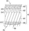
With reference to figure 3, viewgraph of cross-section is illustrated in another example of the assembly of each layer 6 in the module 7 in the chamber 10 that is formed at SPS mould 11.In this example, module 7 has the shape corresponding to the die that is added to the reparation part of damaging parts, in order to recover the original-shape of parts.
According to said method; described die is filled deposit successive layers and the thin layer that forms assembly 6 or multilayer integral: can with the solder brazing powder bed 60 of the face coupling of parts to be repaired; superalloy powder bed 61; the thin protective layer 62 formed by the Ni-Al-Zr compound sheet, and be ZrO by yttria-stabilized zirconia, chemical formula
2Y
2O
3Ceramic powders form and doped with gadolinium oxide Gd
2O
3 Thermal insulation layer 63.
With reference to figure 4, at the sintering step of implementing under above-mentioned specified requirements, make it possible to obtain the preform 2a with component gradient G3, G4 and G5 of multilayer integral 6 forms between each layer and thin layer 60-61-62-63.Sintering solder brazing layer 60 has outer surface 6b, and it can be bonded to the damage face of parts to be repaired, and in solder brazing face 6b, some superalloy material 6s are presented on the surface of preform 2a.
In follow-up solder brazing step as shown in Figure 5, it is that face 20 contacts that the solder brazing face 6b of preform 2a is placed to the complementary region of parts to be repaired 2.Then, heating preform 2a and the temperature along the parts 2 of its placement to the fusion temperature that equals at least hard soldering alloys, for example, for the hard soldering alloys based on silver-colored, be about 700 ℃ in appropriate stove.Then, solder brazing face 6b is bonded in parts to be repaired 2 by the face that diffuses through it 20 of the fusing element of hard soldering alloys.
The invention is not restricted to described and example that illustrate.For example, it can sedimentation chemistry and the multilayer initiation layer of the compatible ceramic material of heat.In addition, in the subsequent deposition step, in case whole parts are reconstructed, coat of metal and thermal insulation layer can add on whole parts afterwards.In this case, protective layer and thermal insulation layer are advantageously peeled off from the surface of damaging parts in advance, and in the situation that do not have these layers to carry out sintering.These layers are then by sintered deposit and being bonded on whole reconstruction means.
Claims (8)
1. for part, repair the method for the heat engine tool parts (2) of superalloy, it is characterized in that, the method comprises: in preparation process, in mould (11) the production module (1,7) of the shell for SPS flash sintering, described module (1,7) be shaped to the die of the reparation part at least of damaging parts (2), to introduce in described module (1,7) solder brazing powder bed (60) and at least one deck form the powder based on superalloy (31, the 61) layer of multilayer integral (6); Then, in sintering step, supercharging and initiation pulse current are by causing the temperature fast rise in the circulation of flash sintering, by being diffused between material and described parts (2), to form subsequently adhesive, temperature, pressure and the duration of described flash sintering circulation are conditioned, and described flash sintering circulation is had at least one temperature stage of stable development and a pressure stage of stable development; What this sintering step produced described multilayer integral (6) form has a component gradient (G3, G4, G5) preform (2a), it has the solder brazing face (6b) that can be bonded on described parts (2) to be repaired, and superalloy material (6s) is presented on the surface of this preform (2a).
2. restorative procedure according to claim 1, wherein regulate temperature, pressure and the duration of described flash sintering circulation, make temperature that it has at least 600 ℃/minutes increase, basically the temperature stage of stable development in scope and pressure stage of stable development between 10Mpa and 100Mpa basically between 1000 ℃ and 2000 ℃.
3. according to claim 1 or restorative procedure claimed in claim 2, the shape of wherein said module (1) is corresponding to the die of whole primitive part, and described superalloy layer (31) forms the bonding continuum by being diffused between material and described parts (2) to be repaired.
4. according to the described restorative procedure of aforementioned claim, wherein in follow-up solder brazing step, the solder brazing face (6b) of the preform of making by this way (2a) is placed as with the zone (20) of described parts (2) to be repaired and contacts, then, by in appropriate stove, heating preform (2a) and the temperature along the described parts (2) of its placement to the fusion temperature that equals at least hard soldering alloys (60), the diffusion bonding of described solder brazing face (6b) by the fusing element of hard soldering alloys is in described parts (2) to be repaired.
5. according to the described restorative procedure of aforementioned claim any one, wherein during the preparatory stage, described coat of metal (32,62) and thermal insulation layer (33,63) are deposited on the layer (31,61) of described superalloy.
6. according to the described restorative procedure of aforementioned claim any one; wherein said coat of metal (32; 62) comprise at least one die formed by Ni, Pt, Hf, Y, Si, Cu, Ag and/or Au; and/or by Ni-Al, at least one die that Ni-Pt-Al and/or Ni-Al-Zr compound form.
7. according to the described restorative procedure of aforementioned claim any one, wherein said thermal insulation layer (33,63) is comprised of the yttria-stabilized zirconia.
According to said method via the heat engine tool parts reparation of flash sintering, that superalloy is made, especially turbine components, it is characterized in that, these parts have by the material of the fusing element of hard soldering alloys diffuse to form with the adhesive of described parts (2) to be repaired bonding (31,6b).
Applications Claiming Priority (3)
| Application Number | Priority Date | Filing Date | Title |
|---|---|---|---|
| FR1151832 | 2011-03-07 | ||
| FR1151832A FR2972379B1 (en) | 2011-03-07 | 2011-03-07 | METHOD FOR LOCALLY RECHARGING DAMAGED THERMOMECHANICAL PIECE AND PART THEREFORE PRODUCED, IN PARTICULAR TURBINE PIECE |
| PCT/FR2012/050459 WO2012120231A1 (en) | 2011-03-07 | 2012-03-06 | Process for local repair of a damaged thermomechanical part and part thus produced, in particular a turbine part |
Publications (2)
| Publication Number | Publication Date |
|---|---|
| CN103415365A true CN103415365A (en) | 2013-11-27 |
| CN103415365B CN103415365B (en) | 2017-01-18 |
Family
ID=43902599
Family Applications (1)
| Application Number | Title | Priority Date | Filing Date |
|---|---|---|---|
| CN201280011974.9A Active CN103415365B (en) | 2011-03-07 | 2012-03-06 | Process for local repair of a damaged thermomechanical part and part thus produced, in particular a turbine part |
Country Status (9)
| Country | Link |
|---|---|
| US (1) | US9221101B2 (en) |
| EP (1) | EP2683509B1 (en) |
| JP (1) | JP6085256B2 (en) |
| CN (1) | CN103415365B (en) |
| BR (1) | BR112013022876A2 (en) |
| CA (1) | CA2828711C (en) |
| FR (1) | FR2972379B1 (en) |
| RU (1) | RU2598018C2 (en) |
| WO (1) | WO2012120231A1 (en) |
Cited By (7)
| Publication number | Priority date | Publication date | Assignee | Title |
|---|---|---|---|---|
| CN106794519A (en) * | 2014-10-14 | 2017-05-31 | 西门子能源有限公司 | The laser gain material manufacture of the three-dimensional part comprising multiple material of forming as one system |
| CN108367360A (en) * | 2015-12-14 | 2018-08-03 | 赛峰航空器发动机 | Abrasion-resistant coatings with variable density |
| CN108430691A (en) * | 2015-12-21 | 2018-08-21 | 通用电气公司 | Repaired turbine components and corresponding repair methods |
| CN109070228A (en) * | 2016-03-14 | 2018-12-21 | 赛峰航空器发动机 | Method for manufacturing wearing plate and repairing turbine shield |
| CN110303259A (en) * | 2019-07-22 | 2019-10-08 | 中国航空制造技术研究院 | The manufacturing method of different alloys Blisk |
| CN110582373A (en) * | 2017-02-22 | 2019-12-17 | 通用电气公司 | Method of manufacturing turbine airfoils and tip components thereof using ceramic core having reference features |
| CN112789130A (en) * | 2018-10-02 | 2021-05-11 | 诺里马特公司 | Method for producing a countermould and method for manufacturing a part with a complex shape using such a countermould |
Families Citing this family (18)
| Publication number | Priority date | Publication date | Assignee | Title |
|---|---|---|---|---|
| US9102015B2 (en) | 2013-03-14 | 2015-08-11 | Siemens Energy, Inc | Method and apparatus for fabrication and repair of thermal barriers |
| EP2840154A1 (en) * | 2013-08-21 | 2015-02-25 | MTU Aero Engines GmbH | Method for producing components from and with laves phases |
| US20160158840A1 (en) * | 2013-11-25 | 2016-06-09 | Marco Cologna | Use of spark plasma sintering for manufacturing superalloy compound components |
| US10350684B2 (en) | 2015-11-10 | 2019-07-16 | General Electric Company | Additive manufacturing method for making complex film holes |
| FR3044946B1 (en) | 2015-12-14 | 2018-01-12 | Safran Aircraft Engines | ABRADABLE COATING WITH VARIABLE DENSITY |
| US11167348B2 (en) | 2017-06-28 | 2021-11-09 | Rolls-Royce Corporation | Joining metal or alloy components using electric current |
| FR3071178B1 (en) * | 2017-09-15 | 2022-02-25 | Safran | METHOD FOR MANUFACTURING A TURBOMACHINE PART BY ADDITIVE MANUFACTURING AND FLASH SINTERING |
| AT520756B1 (en) * | 2017-12-06 | 2019-07-15 | Montanuniv Leoben | METHOD FOR MANUFACTURING A MULTIMATERIAL COMPONENT CONNECTION AND THE MULTIMATERIAL COMPONENT CONNECTION |
| WO2020204872A1 (en) | 2019-03-29 | 2020-10-08 | Siemens Energy, Inc. | Tip repair of a turbine component using a composite tip boron base pre-sintered preform |
| FR3105048B1 (en) * | 2019-12-20 | 2022-08-05 | Safran | MANUFACTURING SOLUTION FOR A MONOBLOC BLADE DISC |
| US11305355B2 (en) | 2020-05-21 | 2022-04-19 | Kilncore Inc. | High temperature, high pressure, powder-based, 3D printed object manufacturing |
| RU2761813C1 (en) * | 2021-03-11 | 2021-12-13 | Федеральное государственное бюджетное учреждение науки Институт гидродинамики им. М.А. Лаврентьева Сибирского отделения Российской академии наук (ИГиЛ СО РАН) | Additive method for obtaining dimension products from conductive ceramics by spark plasma sintering |
| US11541470B2 (en) | 2021-04-02 | 2023-01-03 | General Electric Company | Methods of furnace-less brazing |
| EP4105450A1 (en) | 2021-06-18 | 2022-12-21 | Raytheon Technologies Corporation | Passive clearance control (apcc) system produced by field assisted sintering technology (fast) |
| US12055056B2 (en) | 2021-06-18 | 2024-08-06 | Rtx Corporation | Hybrid superalloy article and method of manufacture thereof |
| CN113462924B (en) * | 2021-06-18 | 2022-03-29 | 中国地质大学(武汉) | A kind of titanium-coated diamond-copper composite material and preparation method thereof |
| US20240165751A1 (en) * | 2022-11-23 | 2024-05-23 | Raytheon Technologies Corporation | Systems and methods of blade leading edge repair using field assisted sintering technology |
| CN115849957B (en) * | 2022-11-25 | 2023-08-11 | 南京航空航天大学 | Rapid repairing method for damage defect of ceramic matrix composite |
Citations (8)
| Publication number | Priority date | Publication date | Assignee | Title |
|---|---|---|---|---|
| US3241956A (en) * | 1963-05-30 | 1966-03-22 | Inoue Kiyoshi | Electric-discharge sintering |
| US3250892A (en) * | 1961-12-29 | 1966-05-10 | Inoue Kiyoshi | Apparatus for electrically sintering discrete bodies |
| US4039330A (en) * | 1971-04-07 | 1977-08-02 | The International Nickel Company, Inc. | Nickel-chromium-cobalt alloys |
| EP0401187A2 (en) * | 1989-06-01 | 1990-12-05 | Abb Stal Ab | Method for reconstruction of blades and vanes in steam turbines at existing erosion damages |
| US5554837A (en) * | 1993-09-03 | 1996-09-10 | Chromalloy Gas Turbine Corporation | Interactive laser welding at elevated temperatures of superalloy articles |
| US6384365B1 (en) * | 2000-04-14 | 2002-05-07 | Siemens Westinghouse Power Corporation | Repair and fabrication of combustion turbine components by spark plasma sintering |
| CN1666834A (en) * | 2001-01-20 | 2005-09-14 | 昆明理工大学 | A kind of method of plasma activated sintering of copper powder |
| US20100237134A1 (en) * | 2006-07-17 | 2010-09-23 | David Vincent Bucci | Repair process for coated articles |
Family Cites Families (11)
| Publication number | Priority date | Publication date | Assignee | Title |
|---|---|---|---|---|
| RU1792805C (en) * | 1990-05-24 | 1993-02-07 | Республиканское Научно-Производственное Объединение "Агропромремонт" | Method of recovering engine cylinder sleeves |
| JPH1046208A (en) * | 1996-07-26 | 1998-02-17 | Tokin Corp | Production of ti-ni base alloy sintered body |
| JPH1143706A (en) * | 1997-07-23 | 1999-02-16 | Ishikawajima Harima Heavy Ind Co Ltd | Repair method for metal parts |
| JP2001335813A (en) * | 2000-05-25 | 2001-12-04 | Japan Atom Energy Res Inst | Fabrication method of structural material with silicon gradient composite structure by spark plasma sintering method |
| JP2003342617A (en) * | 2002-05-30 | 2003-12-03 | Mitsubishi Heavy Ind Ltd | REPAIRED HIGH-TEMPERATURE COMPONENT MADE OF HEAT- RESISTANT ALLOY, REPAIRED GAS-TURBINE BLADE MADE OF Ni- BASED HEAT RESISTANT ALLOY, METHOD FOR REPAIRING GAS- TURBINE BLADE OF Ni-BASED HEAT RESISTANT ALLOY, AND METHOD FOR REPAIRING GAS-TURBINE BLADE MADE OF HEAT RESISTANT ALLOY |
| US7343676B2 (en) * | 2004-01-29 | 2008-03-18 | United Technologies Corporation | Method of restoring dimensions of an airfoil and preform for performing same |
| RU2344913C2 (en) * | 2006-01-10 | 2009-01-27 | Владимир Владимирович Гончаренко | Earth board reworking method |
| RU2354523C1 (en) * | 2007-09-12 | 2009-05-10 | Федеральное государственное унитарное предприятие "Московское машиностроительное производственное предприятие "САЛЮТ" (ФГУП "ММПП "САЛЮТ") | Method of repairing gas turbine engine blade labyrinth seal knife edges |
| FR2932496B1 (en) * | 2008-06-13 | 2011-05-20 | Snecma | METHOD FOR DEPOSITING A THERMAL BARRIER |
| FR2941965B1 (en) * | 2009-02-10 | 2011-05-13 | Snecma | METHOD FOR DEPOSITING A PROTECTIVE LAYER ON A WORKPIECE |
| CN102459685B (en) * | 2009-05-26 | 2014-11-19 | 西门子公司 | Layered coating system with a MCrAlX layer and a chromium-rich layer and method for the production thereof |
-
2011
- 2011-03-07 FR FR1151832A patent/FR2972379B1/en active Active
-
2012
- 2012-03-06 US US14/003,453 patent/US9221101B2/en active Active
- 2012-03-06 EP EP12720222.4A patent/EP2683509B1/en active Active
- 2012-03-06 CA CA2828711A patent/CA2828711C/en active Active
- 2012-03-06 RU RU2013140968/02A patent/RU2598018C2/en active
- 2012-03-06 JP JP2013557155A patent/JP6085256B2/en active Active
- 2012-03-06 BR BR112013022876A patent/BR112013022876A2/en not_active Application Discontinuation
- 2012-03-06 CN CN201280011974.9A patent/CN103415365B/en active Active
- 2012-03-06 WO PCT/FR2012/050459 patent/WO2012120231A1/en active Application Filing
Patent Citations (8)
| Publication number | Priority date | Publication date | Assignee | Title |
|---|---|---|---|---|
| US3250892A (en) * | 1961-12-29 | 1966-05-10 | Inoue Kiyoshi | Apparatus for electrically sintering discrete bodies |
| US3241956A (en) * | 1963-05-30 | 1966-03-22 | Inoue Kiyoshi | Electric-discharge sintering |
| US4039330A (en) * | 1971-04-07 | 1977-08-02 | The International Nickel Company, Inc. | Nickel-chromium-cobalt alloys |
| EP0401187A2 (en) * | 1989-06-01 | 1990-12-05 | Abb Stal Ab | Method for reconstruction of blades and vanes in steam turbines at existing erosion damages |
| US5554837A (en) * | 1993-09-03 | 1996-09-10 | Chromalloy Gas Turbine Corporation | Interactive laser welding at elevated temperatures of superalloy articles |
| US6384365B1 (en) * | 2000-04-14 | 2002-05-07 | Siemens Westinghouse Power Corporation | Repair and fabrication of combustion turbine components by spark plasma sintering |
| CN1666834A (en) * | 2001-01-20 | 2005-09-14 | 昆明理工大学 | A kind of method of plasma activated sintering of copper powder |
| US20100237134A1 (en) * | 2006-07-17 | 2010-09-23 | David Vincent Bucci | Repair process for coated articles |
Non-Patent Citations (2)
| Title |
|---|
| DANIEL MONCEAU ETAL.: "Thermal Barrier Systems and Multi-Layered Coatings Fabricated by Spark Plasma Sintering for the Protection of Ni-Base Superalloys", 《MATERIALS SCIENCE FORUM》, vol. 654656, 30 June 2010 (2010-06-30), pages 1826 * |
| J. SCHMIDT ETAL.: "Spark Plasma Sintering of Intermetallics and Metal Matrix Composites", 《EURO PM2005》, 5 October 2005 (2005-10-05), pages 93 - 98 * |
Cited By (11)
| Publication number | Priority date | Publication date | Assignee | Title |
|---|---|---|---|---|
| CN106794519A (en) * | 2014-10-14 | 2017-05-31 | 西门子能源有限公司 | The laser gain material manufacture of the three-dimensional part comprising multiple material of forming as one system |
| CN106794519B (en) * | 2014-10-14 | 2019-05-28 | 西门子能源有限公司 | The laser gain material of the three-dimensional part comprising multiple material of being formed as one system manufactures |
| CN108367360A (en) * | 2015-12-14 | 2018-08-03 | 赛峰航空器发动机 | Abrasion-resistant coatings with variable density |
| CN108430691A (en) * | 2015-12-21 | 2018-08-21 | 通用电气公司 | Repaired turbine components and corresponding repair methods |
| US11077527B2 (en) | 2015-12-21 | 2021-08-03 | General Electric Company | Modified components and methods for modifying components |
| CN109070228A (en) * | 2016-03-14 | 2018-12-21 | 赛峰航空器发动机 | Method for manufacturing wearing plate and repairing turbine shield |
| CN110582373A (en) * | 2017-02-22 | 2019-12-17 | 通用电气公司 | Method of manufacturing turbine airfoils and tip components thereof using ceramic core having reference features |
| CN110582373B (en) * | 2017-02-22 | 2022-04-12 | 通用电气公司 | Method of manufacturing turbine airfoils and tip components thereof using ceramic core having reference features |
| CN112789130A (en) * | 2018-10-02 | 2021-05-11 | 诺里马特公司 | Method for producing a countermould and method for manufacturing a part with a complex shape using such a countermould |
| CN110303259A (en) * | 2019-07-22 | 2019-10-08 | 中国航空制造技术研究院 | The manufacturing method of different alloys Blisk |
| CN110303259B (en) * | 2019-07-22 | 2021-06-08 | 中国航空制造技术研究院 | Method for manufacturing dissimilar alloy blisk structure |
Also Published As
| Publication number | Publication date |
|---|---|
| US9221101B2 (en) | 2015-12-29 |
| FR2972379B1 (en) | 2014-01-17 |
| CA2828711C (en) | 2019-04-02 |
| US20130344347A1 (en) | 2013-12-26 |
| JP6085256B2 (en) | 2017-02-22 |
| JP2014513207A (en) | 2014-05-29 |
| FR2972379A1 (en) | 2012-09-14 |
| EP2683509B1 (en) | 2019-02-27 |
| CN103415365B (en) | 2017-01-18 |
| CA2828711A1 (en) | 2012-09-13 |
| EP2683509A1 (en) | 2014-01-15 |
| RU2013140968A (en) | 2015-04-20 |
| WO2012120231A1 (en) | 2012-09-13 |
| BR112013022876A2 (en) | 2016-12-06 |
| RU2598018C2 (en) | 2016-09-20 |
Similar Documents
| Publication | Publication Date | Title |
|---|---|---|
| CN103415365A (en) | Process for local repair of a damaged thermomechanical part and part thus produced, in particular a turbine part | |
| US9175568B2 (en) | Methods for manufacturing turbine components | |
| EP2291254B1 (en) | Method of making a combustion turbine component from metallic combustion turbine subcomponent greenbodies | |
| JP2014513207A5 (en) | ||
| CN105710377B (en) | Composite additive manufacturing method using composite additive manufacturing features for composite components | |
| US9254537B2 (en) | Plural layer putty-powder/slurry application method for superalloy component crack vacuum furnace healing | |
| US9085980B2 (en) | Methods for repairing turbine components | |
| CN102825426B (en) | Use the method that multiple filler manufactures application member | |
| US20110016717A1 (en) | Method of Making a Combustion Turbine Component Having a Plurality of Surface Cooling Features and Associated Components | |
| JP6595593B2 (en) | Method for manufacturing turbine engine component | |
| CN103949646B (en) | A kind of preparation method of Nb-Si based ultra-high temperature alloy turbine blade | |
| JP2014177938A (en) | Component with micro cooling laser deposited material layer and method of manufacturing the same | |
| TW200524692A (en) | Method for repairing machine part, method for forming restored machine part, method for manufacturing machine part, gas turbine engine, electric discharge machine, method for repairing turbine component, and method for forming restored turbine component | |
| CN102248280A (en) | Thermit reaction foil, manufacturing method thereof and application thereof to welding process | |
| JP7184478B2 (en) | Methods of Repairing Components Using Additive Manufacturing Exchange Coupons and Alloys for Additive Manufacturing | |
| EP3085472B1 (en) | Method of manufacturing a turbine blisk through hot isostatic pressing using a metal core | |
| CN110205626B (en) | Functionally graded thermal barrier coating and preparation method thereof | |
| CN109822248A (en) | A hot isostatic pressing-brazing composite forming method for thin-walled structures | |
| CN115194284A (en) | Furnace-free brazing method | |
| EP2236237A1 (en) | An arrangement for explosion welding a hot gas component of a turbine and a method thereof | |
| EP4335569A1 (en) | Additively depositing braze material | |
| CN1971861A (en) | Preparation method of high-thermal conductivity electronic packaging shell with laser welding capacity | |
| CN117328007A (en) | Methods and systems for thermal spraying braze alloy materials onto nickel-based components to facilitate high-density braze joints with low discontinuities |
Legal Events
| Date | Code | Title | Description |
|---|---|---|---|
| C06 | Publication | ||
| PB01 | Publication | ||
| SE01 | Entry into force of request for substantive examination | ||
| SE01 | Entry into force of request for substantive examination | ||
| C14 | Grant of patent or utility model | ||
| GR01 | Patent grant |