CN103002824A - Device and method for securing a bone implant - Google Patents
Device and method for securing a bone implant Download PDFInfo
- Publication number
- CN103002824A CN103002824A CN2011800218097A CN201180021809A CN103002824A CN 103002824 A CN103002824 A CN 103002824A CN 2011800218097 A CN2011800218097 A CN 2011800218097A CN 201180021809 A CN201180021809 A CN 201180021809A CN 103002824 A CN103002824 A CN 103002824A
- Authority
- CN
- China
- Prior art keywords
- implant
- bone
- section
- anchor
- radius
- Prior art date
- Legal status (The legal status is an assumption and is not a legal conclusion. Google has not performed a legal analysis and makes no representation as to the accuracy of the status listed.)
- Granted
Links
Images


Classifications
-
- A—HUMAN NECESSITIES
- A61—MEDICAL OR VETERINARY SCIENCE; HYGIENE
- A61B—DIAGNOSIS; SURGERY; IDENTIFICATION
- A61B17/00—Surgical instruments, devices or methods
- A61B17/56—Surgical instruments or methods for treatment of bones or joints; Devices specially adapted therefor
- A61B17/58—Surgical instruments or methods for treatment of bones or joints; Devices specially adapted therefor for osteosynthesis, e.g. bone plates, screws or setting implements
- A61B17/88—Osteosynthesis instruments; Methods or means for implanting or extracting internal or external fixation devices
- A61B17/885—Tools for expanding or compacting bones or discs or cavities therein
- A61B17/8852—Tools for expanding or compacting bones or discs or cavities therein capable of being assembled or enlarged, or changing shape, inside the bone or disc
- A61B17/8858—Tools for expanding or compacting bones or discs or cavities therein capable of being assembled or enlarged, or changing shape, inside the bone or disc laterally or radially expansible
-
- A—HUMAN NECESSITIES
- A61—MEDICAL OR VETERINARY SCIENCE; HYGIENE
- A61B—DIAGNOSIS; SURGERY; IDENTIFICATION
- A61B17/00—Surgical instruments, devices or methods
- A61B17/56—Surgical instruments or methods for treatment of bones or joints; Devices specially adapted therefor
- A61B17/58—Surgical instruments or methods for treatment of bones or joints; Devices specially adapted therefor for osteosynthesis, e.g. bone plates, screws or setting implements
- A61B17/68—Internal fixation devices, including fasteners and spinal fixators, even if a part thereof projects from the skin
- A61B17/80—Cortical plates, i.e. bone plates; Instruments for holding or positioning cortical plates, or for compressing bones attached to cortical plates
- A61B17/8061—Cortical plates, i.e. bone plates; Instruments for holding or positioning cortical plates, or for compressing bones attached to cortical plates specially adapted for particular bones
-
- A—HUMAN NECESSITIES
- A61—MEDICAL OR VETERINARY SCIENCE; HYGIENE
- A61F—FILTERS IMPLANTABLE INTO BLOOD VESSELS; PROSTHESES; DEVICES PROVIDING PATENCY TO, OR PREVENTING COLLAPSING OF, TUBULAR STRUCTURES OF THE BODY, e.g. STENTS; ORTHOPAEDIC, NURSING OR CONTRACEPTIVE DEVICES; FOMENTATION; TREATMENT OR PROTECTION OF EYES OR EARS; BANDAGES, DRESSINGS OR ABSORBENT PADS; FIRST-AID KITS
- A61F2/00—Filters implantable into blood vessels; Prostheses, i.e. artificial substitutes or replacements for parts of the body; Appliances for connecting them with the body; Devices providing patency to, or preventing collapsing of, tubular structures of the body, e.g. stents
- A61F2/02—Prostheses implantable into the body
- A61F2/28—Bones
Landscapes
- Health & Medical Sciences (AREA)
- Orthopedic Medicine & Surgery (AREA)
- Life Sciences & Earth Sciences (AREA)
- Surgery (AREA)
- Animal Behavior & Ethology (AREA)
- General Health & Medical Sciences (AREA)
- Biomedical Technology (AREA)
- Heart & Thoracic Surgery (AREA)
- Veterinary Medicine (AREA)
- Engineering & Computer Science (AREA)
- Public Health (AREA)
- Molecular Biology (AREA)
- Nuclear Medicine, Radiotherapy & Molecular Imaging (AREA)
- Medical Informatics (AREA)
- Neurology (AREA)
- Cardiology (AREA)
- Oral & Maxillofacial Surgery (AREA)
- Transplantation (AREA)
- Vascular Medicine (AREA)
- Prostheses (AREA)
- Surgical Instruments (AREA)
Abstract
Devices and methods for securing a bone implant are provided. The implant may be an expandable implant. The implant may be a non-expandable implant. The implant may be used to repair bone fractures. The implant may be secured to the bone by an anchor. The implant may include an anchor receiving structure. The anchor receiving structure may be configured to guide an anchor into cortical bone. The anchor receiving structure may be configured to receive an anchor driven through cortical bone. The implant may include a bone engaging member configured to engage cancellous bone. The implant may comprise different profiles. The different profiles may be configured to secure the implant. The contour may be configured to support the bone. The implant may have different bending properties configured to position the implant in the bone. The implant may be configured to receive an anchor driven through the outside of the bone.
Description
The cross reference of related application
The application is the U.S. Provisional Application No.61/311 that submitted on March 8th, 2010, the U.S. Provisional Application No.61/378 that on August 31st, 494 and 2010 submitted to, 494 non-provisional application, whole disclosures of these two provisional application are incorporated this paper into by the mode of reference.
Technical field
Each side of the present disclosure relates to and is provided for the device and method that fixed part is deployed in the implant in the bone.Particularly, the present invention relates to for utilize to insert in the bone and be fixed to the device and method of the device repair of bone fractures on the bone.
Background technology
Human body comprises long bone, short bone, flat bone, irregular bone and sesamoid bone.Long bone is characterised in that the stage casing.The stage casing of long bone classifies as the backbone usually.The end of this bone classifies as epiphysis usually.The bone of transition classifies as the metaphysis bone usually between stage casing and end.
The several sections of fracture of stage casing or end bone need to be to produce aligning and the stability of fully fixing mode along a plurality of directions.
But stage casing fracture and end bone fracture are fundamental differences.Loading condition, fracture pattern, required aligning and compression stress are to promote that healing is different.The stage casing fracture has the sufficient bone material on the either side of crackle, and wherein anchor is driven in described crackle.End bone fracture, the especially fracture on articular surface can have thin cortical bone, soft spongy bone and minimum anchor station.
The stage casing fracture is tending towards mainly loading with bending and torsion.End bone fracture is tending towards loading with the multiaxial stress pattern with complexity.Thus, the stage casing restorative procedure can be unsuitable for repairing end bone fracture.
Exist two kinds to be used for the fixedly primary categories of long bone fracture of operation: (1) is positioned at the device (inner fixing) of skin; And (2) extended device (external stability) from skin.The internal fixation approaches that is used for the long bone operation that has two kinds of common types: (a) be screwed to plate on the bone outside; Or the bar that (b) advances downwards from the bone center.
Bar, nail or implant are more effective reduce aspect soft-tissue trauma and the complication as far as possible in the marrow.In addition, the suitable size of implant helps again aligning and the healing of fracturing.The accurate size of implant can be guaranteed the accurate coupling of implant device and patient's anatomical structure.
The implant that is deployed in the pulp cavity of bone is extensile.Extensible implant can provide anatomical structure accurately to aim at and allow the suitable size of implant.But fracture need to be to produce along a plurality of directions fully aligning and the stability of fixing mode.
Thus, it is desirable to be provided for the device and method that fixed part is deployed in the implant of bone inboard.
Description of drawings
Fig. 1 shows the axonometric chart according to the exemplary means of principle of the present invention;
Fig. 2 shows the present invention can be in conjunction with the exemplary anatomical structure of practice;
Fig. 3 shows together with another exemplary means according to the exemplary anatomical structure of principle of the present invention;
Fig. 4 shows along the sectional view of the line 4-4 intercepting of installing shown in Fig. 3;
Fig. 5 shows the partial section of installing shown in Fig. 3;
Fig. 6 shows a part of installing shown in Fig. 5;
Fig. 7 A shows the sectional view according to the device of principle of the present invention;
Fig. 7 B shows the sectional view that installs shown in Fig. 5;
Fig. 7 C show device shown in Fig. 5 be in state different conditions shown in Fig. 7 B in sectional view;
Fig. 8 shows the axonometric chart of device shown in Fig. 1 in the view different from view shown in Fig. 1;
Fig. 9 shows the axonometric chart according to the exemplary means of principle of the present invention;
Figure 10 shows the axonometric chart according to the exemplary means of principle of the present invention;
Figure 11 A shows the axonometric chart according to the exemplary means of principle of the present invention;
Figure 11 B show shown in Figure 11 device with the different views of view shown in Figure 11 in sectional view;
Figure 12 shows the axonometric chart according to the exemplary means of principle of the present invention;
Figure 13 shows the axonometric chart according to the exemplary means of principle of the present invention;
Figure 14 shows the axonometric chart according to the exemplary means of principle of the present invention;
Figure 15 shows the cross section that installs shown in Figure 14;
Figure 16 shows can be for the manufacture of the information of installing shown in Figure 15;
Figure 17 shows another axonometric chart that installs shown in Fig. 3;
Figure 18 shows the sectional view that installs shown in Figure 17;
Figure 19 shows the cross section that installs shown in Figure 17;
Figure 20 shows the axonometric chart according to the exemplary means of principle of the present invention;
Figure 21 shows can be for the manufacture of the information according to the device of principle of the present invention;
Figure 22 shows can be for the manufacture of the information according to the device of principle of the present invention;
Figure 23 A shows can be for the manufacture of the information according to the device of principle of the present invention;
Figure 23 B shows the axonometric chart according to the exemplary means of principle of the present invention;
Figure 24 A shows can be for the manufacture of the information according to the device of principle of the present invention;
Figure 24 B shows the axonometric chart according to the exemplary means of principle of the present invention;
Figure 25 shows the axonometric chart according to the exemplary means of principle of the present invention;
Figure 26 shows the front view that installs described in Figure 25;
Figure 27 shows can be for the manufacture of the information according to the device of principle of the present invention;
Figure 29 shows the axonometric chart according to the exemplary means of principle of the present invention;
Figure 30 shows the axonometric chart according to the exemplary means of principle of the present invention;
Figure 31 A shows the axonometric chart according to the exemplary means of principle of the present invention;
Figure 31 B shows can be for the manufacture of the information according to the device of principle of the present invention;
Figure 31 C shows can be for the manufacture of the information according to the device of principle of the present invention;
Figure 32 shows the side view according to the exemplary means of principle of the present invention;
Figure 33 shows the axonometric chart according to the exemplary means of principle of the present invention;
Figure 34 shows the end-view that installs shown in Figure 33;
Figure 35 shows the axonometric chart according to the exemplary means of principle of the present invention;
Figure 36 shows the end-view that installs shown in Figure 35;
Figure 37 shows device shown in Figure 35 together with the axonometric chart of exemplary anatomical structure;
Figure 38 shows the axonometric chart according to the exemplary means of principle of the present invention;
Figure 39 shows the axonometric chart according to the exemplary means of principle of the present invention;
Figure 40 shows the axonometric chart according to the exemplary means of principle of the present invention
Figure 41 shows the cross section of a part of installing shown in Figure 40;
Figure 42 (A)-Figure 42 (C) shows the side view according to the exemplary means of principle of the present invention;
Figure 43 shows the front view of exemplary human skeleton;
Figure 44 shows the partial section of fractured bones;
Figure 45 shows for the preparation of the axonometric chart according to the exemplary means of the exemplary anatomical structure of principle of the present invention.
The specific embodiment
Apparatus and method for the implant that is fixed for bone are provided.Implant can be fixed on the bone to repair the crackle in the bone.Described implant can be extensible implant.Described implant can be for stretching implant.Described implant can be any suitable implant.For example, described implant can be for such as shown in the U.S. Patent Application Publication No.2009/0182336A1 and the implant the implant of describing, and the full content of this announcement is incorporated this paper into by the mode of reference.
Described bone can use any suitable technology for example at U.S. Patent application No.13/009, approaches and prepares with disclosed technology shown in 657, and the full content of this application is incorporated this paper into by the mode of reference.
The name of submitting on March 8th, 2011 be called the similar pending trial U.S. Patent application No. of " being used for the apparatus and method that bone is repaired "/... ... full content incorporate this paper into by the mode of reference.The similar pending trial U.S. Provisional Application No.61/450 that on March 7th, 2011 submitted to, 112 full content is incorporated this paper into by the mode of reference.
Described apparatus and method can relate to the extensible implant that fixed part is deployed in the fractured bones inboard.Described apparatus and method can relate to the stretching, extension of apparatus in the interior zone of described bone.Described stretching, extension can relate to extension means or the technology of any appropriate, for example one or more shown in the U.S. Patent Application Publication No.2009/0182336A1 and in the mechanism of describing and the technology.
Described implant can have the first base portion and the second base portion.Described implant can have the bone implant parts that extend between the first base portion and described the second base portion being.Described the first base portion and described the second base portion can limit longitudinal axis.Described bone implant parts can be with respect to described longitudinal axis corresponding to the relative displacement deflection along described axis of described the first base portion and described the second base portion.
Described device can comprise: the first noumenon, and described the first noumenon and described axis are substantially coaxial and vertically be fixed on described the first base portion; The second body, described the second body and described axis are substantially coaxial and vertically be fixed on described the second base portion; And elongated engagement member, described elongated engagement member is configured to vertically fix the distance between described the first noumenon and described the second body.
Described distance can have the maximum corresponding with the complete folded state of described implant.Described distance can have the minima corresponding with the full extension state of described implant.The distance of the arbitrary value in described elongated engagement member can be configured to be vertically fixed in from about described maximum to the scope of about described minima.
Described complete folded state can be configured to pass corresponding to wherein said implant the state in the access hole in the described bone.Described full extension state can be corresponding to wherein said implant state in the lateral expansion of described bone under standard temperature and pressure (STP).Standard temperature and pressure (STP) can be arbitrary standards temperature and arbitrary standards pressure, for example about 0 degree centigrade and about 1 atmospheric pressure.
Described distance can be controlled by the length of controlling described implant the stretching, extension of described implant.Described distance can be corresponding to the treatment length of described bone implant.Described distance can be corresponding to the treatment radius of described bone implant.
Described slender member can be constructed for integral type, and can be for being configured to all structures operated in conjunction with described implant, and described elongated engagement member can be configured to separately fixing described distance.
Described distance can be corresponding to the extended configuration of described bone implant.Under extended configuration, described implant can be provided for the structure support of bone.Described implant can be locked under the extended configuration.Releasing loose implant can be fixed under the extended configuration.Described implant can lock or be fixed under the extended configuration, so that the remaining radially outer pressure that acts on the inwall of described bone can significantly reduce or eliminate.
Under contraction state, described implant can be provided for the structure support of described bone.Described implant can be locked under the contraction state.Described implant can be fixed under the contraction state.Described implant can lock or be fixed under the contraction state, so that the remaining radially outer pressure that acts on the inwall of described bone can significantly reduce or eliminate.
Described elongated engagement member can be configured to apply tension force between described body and described the second body.Described slender member can for the integral type structure and for to be configured to all structures operated in conjunction with described implant, described elongated engagement member can be configured to apply separately tension force.
In certain embodiments, when described slender member fixing described apart from the time, described slender member can be outside engages with described the first noumenon and the outside engages with described the second body in described the second body in described the first noumenon.
Described the first noumenon can comprise the first threaded sleeve.Described the second body can comprise the second threaded sleeve.Described slender member can comprise and is configured to the threaded portion that engages with described the first threaded sleeve and described the second threaded sleeve.
Described threaded portion is can be enough meticulous is avoiding changing significantly described distance when engaging with described the second threaded sleeve after described the first threaded sleeve engages with the described threaded portion of box lunch.
Described the second body can have external diameter.Described the first noumenon can comprise having internal diameter greater than the cylindrical shape part of the external diameter of described the second body.Described cylindrical shape part can be configured to receive the part of described the second body.
Described device can comprise the support extension between described the first base portion and described the second base portion.Described support can comprise described bone implant parts.Described support can be configured to support bone.
In certain embodiments, when described the first base portion when described the second base portion moves, described support can be away from described longitudinal axis and stretch.
Described implant can comprise the grappling substrate.Described grappling substrate can be arranged between described longitudinal axis and the described support.
In certain embodiments, the grappling substrate can be extended between described the first base portion and described the second base portion.Described grappling substrate can comprise described bone implant parts, and can be configured to support bone.
In certain embodiments, when described the first base portion when described the second base portion moves, described grappling substrate can be away from described longitudinal axis and stretch.
Described implant can comprise support, and described support is positioned at than the large radial distance of described grappling substrate with respect to described longitudinal axis.
Protuberance can be from described the first base portion and described support one or two extension.Pouch can be arranged in described the first base portion and the described support one or two.Described protuberance can be biased, so that it engages with described pouch.Described support can engaging substantially vertically and being rotatably fixed on described the first base portion by described protuberance and described pouch.
In certain embodiments, when described distance was fixed, described grappling substrate can be moved and can be around described longitudinal axis angular shift along described longitudinal axis.
Described method can comprise a kind of method of stretching, extension diameter of the bone implant be used to being controlled at the bone inboard.Described method can comprise the length of controlling described implant by the distance of use between fixing described the first base portion of the slender member that extends between the first base portion and the second base portion and described the second base portion.Described the first and second base portions can be for basic on same straight line.Described method can comprise the described slender member that closes at described bone inboard by closure access hole, and described implant is transported in the described bone by described access hole.
In certain embodiments, described implant can have complete folded state and full extension state.Described complete folded state can be configured to pass corresponding to wherein said implant the state in the access hole that is arranged in described bone.Described full extension state is corresponding to wherein said implant state in described bone lateral expansion under standard temperature and pressure (STP).When described implant had complete folded state and full extension state, described method can comprise described distance is fixed on following value: be not more than the maximum corresponding with the described complete folded state of described implant; And be not less than the minima corresponding with the described full extension state of described implant.
A kind of method that is used for the treatment of fracture is provided.Described method can comprise with respect to the second displacement that reduces of fracturing the first fracture to be set, so that described fracture reduces temporarily.Described method can comprise implant is deployed in the interior zone of described bone that described implant has the stretched dimensions larger than the correspondingly-sized of described interior zone.Described method can comprise to be inserted the tension force memory element in the described implant, described tension force memory element prevent described implant with described first the fracture be away from described reduce the displacement urge.
The first sliver passes described the first sliver and described the second sliver with respect to the setting that reduces to be shifted of the second sliver so that described sliver reduces to comprise Ji Shi steel wire (K-wire) inserted temporarily.
Tension force memory element (its prevent described implant is away from described the first sliver describedly reduce displacement and urge) inserted to comprise the fixedly axial distance between the first interface and the second interface in the described implant.Described first interface and described the second interface can be configured to make constantly described implant stretching, extension and folding when separating mobile constantly described implant when being pulled together.
Regulate described axial distance before described method can be included in and dispose and after inserting.Fixedly first interface and axial distance between the second interface can comprise described tension force memory element is advanced so that the first noumenon that is fixed on the described first interface engages with the second body on being fixed to described the second interface along described axial distance.Described tension force memory element is advanced to comprise and make described tension force memory element rotation.
The device that is used for extensible bone implant is provided.Described extensible implant can comprise interface, central shaft member and supporting member.Described supporting member can comprise first end and the second end.Described first end and described the second end can be spaced apart from each other along described central shaft member.Described supporting member can have intermediate section, and described intermediate section is configured to radially be away from the deflection of described central shaft member when described implant stretches.
Described interface can comprise the supporting member terminal.Described supporting member terminal can be configured to: between the extensin period of described implant described the second end is vertically fixed with respect to described central shaft member; And between described extensin period, described the second end is radially fixed with respect to described central shaft member.
In certain embodiments, described supporting member terminal can comprise the gap otch for described supporting member, so that described the second end can have the motion angle range between described extensin period.
Described the second end can comprise protuberance.Described supporting member terminal can comprise big envelope.Described big envelope can be configured to seal described protuberance.Described otch can be configured to cross described big envelope.
Described big envelope can comprise the first big envelope member.Described big envelope can comprise the second big envelope member.Described the second big envelope member can be configured to spaced apart with described the first big envelope member and described protuberance is incorporated in the described big envelope.
Described the first big envelope member can comprise the stop surfaces that limits described motion angle range.Described stop surfaces can comprise the end of described otch.
Described the second big envelope member can comprise the stop surfaces that limits described motion angle range.
Described supporting member terminal can be configured to around described central shaft member rotation.
Described supporting member terminal can be rotatably fixing with respect to described central shaft member.
Provide and be used for stabilization of bony implant apparatus and method.Described bone can have the access hole for delivery of described implant.Described access hole can have hole wall.
Described implant can comprise the regulator.Described regulator can comprise slender member.Described slender member can be configured to extend along described hole and extend between described implant (when described implant is deployed in the described hole) and anchor reception structure.Described anchor receives structure and can be enough be driven into anchor in the described hole wall as reception.Described regulator can comprise that one or more anchors receive structure.
Described slender member can comprise extension, and described extension extends beyond described anchor reception structure and is configured to be connected with the support plate articulated type.
Described extension can be included as the first surface around the periphery of described anchor receiving member.Described support plate can comprise the second surface with described first surface complementation.The pull strength that comes from the anchor that is received by described anchor reception structure can be configured to support described second surface against described first surface.
Described slender member can be configured to limit the rotation of described implant in described hole.Described slender member can be configured to limit described implant along the axially-movable in described hole.Described slender member can be configured to limit described implant in described hole rotation and described implant along the axially-movable in described hole.
Described implant can comprise the locking mechanism be used to the shape of keeping described implant.Described locking mechanism can be configured to by the screw locking of inserting in the described access hole.Described screw can be regulated after described anchor reception structure has received described anchor.
Described regulator can comprise the support plate that anchors on the described bone.Described support plate can be basically parallel to the longitudinal axis setting of described bone.Described support plate can be configured to limit described slender member rotatablely moving around the central axis in described hole.
Described support plate can comprise the second anchor reception structure that is configured to receive described anchor.
Described support plate can be configured to limit described slender member along the axially-movable in described hole.
Described support plate can be configured to limit described slender member in described hole rotation and described slender member along the axially-movable in described hole.
Described support plate can comprise the second anchor reception structure that is configured to receive described anchor.
Described support plate can comprise that the 3rd anchor of the anchor in the outer surface that is configured to receive the cortical wall that is driven to described bone receives structure.
Described regulator can comprise first edge adjacent with described the first anchor reception structure and receive the second adjacent edge of structure with described the first anchor.Described support plate can comprise the second anchor reception structure that is configured to receive described anchor.Described the first edge and described the second edge can limit pivot axis.Described anchor can be configured to described support plate is fixed as with described bone photo and contact and be fixed in the position of the outer surface that is basically parallel to described bone.
In the embodiment that comprises pivot axis of described regulator, described support plate can be configured to limit the rotation of described slender member in described hole, described slender member along axially-movable and/or the axially-movable of described slender member in described hole in described hole.
In the embodiment that comprises pivot axis of described regulator, described support plate can not pass to described slender member with the remarkable bending moment around described pivot axis.
In the embodiment that comprises pivot axis of described regulator, described support plate can comprise that the 3rd anchor of the anchor in the outer surface that is configured to receive the cortical wall that is driven to described bone receives structure.
Described regulator can comprise the support plate that anchors on the described bone and be basically parallel to the longitudinal axis setting of described bone.Described support plate can comprise the first recess and the second recess.Described slender member can comprise ridge.
Described the first recess and described the second recess can be configured to engage and limit the rotation of described slender member in described hole with described ridge.Described the first recess and described the second recess can be configured to engage and limit described slender member along the axially-movable in described hole with described ridge.Described the first recess and described the second recess can be configured to engage and limit described slender member with described ridge and wind rotation perpendicular to the axis of the longitudinal axis of described implant.
In certain embodiments, described slender member can be configured to be arranged in the described access hole after described implant has been deployed in described bone inboard.
Described implant can be configured to dispose by the access hole of the cortical wall that is arranged in described bone.In certain embodiments, described regulator can comprise slender member, when described implant is deployed in the described bone, described slender member extends between described implant and anchor reception structure, and described anchor receives structure and is configured to receive the interior anchor of outer surface that is driven to described cortical wall.Described slender member can be configured to be out of shape that described anchor is received structure along the described outer surface setting of described cortical wall.
Described regulator can comprise the support plate that is configured to be arranged on the described slender member.The described support plate that is arranged on the described slender member can limit described slender member around the rotation of the central axis in described hole.Being arranged on described support plate on the described slender member can limit described slender member and wind rotation transverse to the axis of described slender member.
In some embodiment that comprise the slender member that is configured to be out of shape, described slender member can be configured to be attached on the described implant after described implant is deployed in the described bone.
In certain embodiments, described regulator can comprise the position that receives structure for anchor, and described anchor receives structure and is configured to receive the interior anchor of outer surface that is driven to described cortical wall.Slender member can be configured to extend between described implant and described position after implant is deployed in the described bone.Support plate can be arranged on the described slender member and be configured to limit described slender member around the axially-movable transverse to described slender member of the rotation of the central axis in described access hole and described slender member.
Comprising some embodiment of regulator that receive the position of structure for anchor, described regulator can be attached on the described implant after described implant be deployed in the described bone.
Described regulator can comprise slender member, and described slender member is configured to extend between described implant and support lantern ring after implant is deployed in the described bone.Described support lantern ring can be bearing in the opening part in described access hole.Described slender member can terminate in described support lantern ring place.Described support lantern ring can be basically parallel to the outer surface of described cortical wall.
Some embodiment with described regulator of support lantern ring can comprise that anchor receives structure, and described anchor receives structure and is configured to receive the interior anchor of described outer surface that is driven to described cortical wall.
In some embodiment of described regulator, the angle between the central axis in described access hole and the central axis of described implant can be regulated.Described regulator can comprise the locking mechanism that is configured to lock described adjustable-angle.Described slender member can comprise articular surface.Described adjustable-angle can be between between 0 degree and 5 degree, between between 0 degree and 10 degree, between between 0 degree and 15 degree, between between 0 degree and 20 degree, between between 0 degree and 25 degree, between between 0 degree and 30 degree, between between 0 degree and 35 degree, between between 0 degree and 45 degree, between 0 degree and 90 degree or in what its suitable angular range in office.
The system and method that is used for bone implant is fixed on bone is provided.Described system can comprise the extensible net with front and back.Described net can be configured to be inserted in the inside of described bone.Described net can comprise having the extensible unit that stretches diameter.
Described system can comprise anchor, and described anchor can be configured to be fixed to the sliver of described bone described extensible online when extensible net is positioned at described bone when inboard.Described anchor can have slender axles and connected structure, wherein said slender axles are used for penetrating described unit from described front, and described connected structure laterally is away from described axle extension and can be configured to engage tension force to be applied between described unit and the described bone splits stricture of vagina with the described back side of described unit.Described axle can have shaft diameter, described shaft diameter with respect to described stretching, extension diameter enough greatly to prevent the described back side disengagement of described connected structure and described unit when apply described tension force.
Described stretching, extension diameter can be when being located in the extended configuration of described connected structure before engaging with the described back side of described unit when described extensible net the diameter of described unit.
Described stretching, extension diameter can be for being arranged in when described extensible net that extended configuration, described connected structure engage with the described back side of described unit and the diameter of described unit during by described tension force elastic deformation, described unit.
Described stretching, extension diameter can be for being arranged in when described extensible net that extended configuration, described connected structure engage with the described surface of described unit and the diameter of described unit during by described tension force elastic deformation, described unit.
Described anchor can be screw.Described connected structure can be helical thread section.When described anchor is screw and described connected structure when being helical thread section, the one or more breaking strains based on described unit in described screw root diameter (RD), described screw thread diameter and the pitch are chosen.
When described anchor is screw and described connected structure when being helical thread section, the one or more elastic deformation limits based on described unit in described screw root diameter (RD), described screw thread diameter and the pitch are chosen.
When anchor is when being helical thread section for the described connected structure of screw, screw tolerance can be chosen based on the fracture strength of described unit.
Described screw tolerance can be the screw major diameter.Described screw tolerance can be the screw average diameter.Described screw tolerance can be the screw minor diameter.Described screw tolerance can be pitch.Described screw tolerance can be the screw thread angle.
The apparatus and method that are used for the parts of bone fixation implant are provided.Described device can comprise carriage, and described carriage can be configured to receive bone anchor.Described device can comprise extended element, and described extended element can be configured to support described carriage with respect to the bone implant that is deployed in described bone inboard.Described device can comprise fastening assembly, and described fastening assembly is configured to described carriage is fastened on the described extension and with described extension and is fastened on the described implant.
Described fastening assembly can comprise that the first state that wherein said carriage can move with respect to described implant and wherein said carriage are with respect to the second state of described implant locking.
In described the first state, described carriage can be from apart from the first distance moving of described implant to the second distance apart from described implant.
In described the first state, described carriage can from respect to the first angular movement of described implant to the second angle with respect to described implant.
In described the first state, described carriage can from apart from the first distance moving of described implant to apart from the second distance of described implant and from respect to the first angular movement of described implant to the second angle with respect to described implant.
Described fastening assembly can comprise securing member.Described securing member can be configured to described extension is urged and cause friction between described extension and described carriage towards described implant.
Described device can comprise the stretching, extension lining.Described securing member can be configured to described stretching, extension lining is driven to urge and make described extension to stretch to disturb mutually with the motion of described carriage towards described implant described extension towards described implant.
Described carriage can have tubular sections.Described extension can have the tubular sections that is positioned at described carriage tubular sections.Described stretching, extension lining can comprise a part that is positioned at described extension tubular sections.Described securing member can comprise screw.Described screw can have a part that is positioned at described stretching, extension lining.
The apparatus and method that are used for bone implant are provided.Described bone implant can comprise the central shaft member.Described bone implant can comprise can be around described central shaft member by the first extensible net of coaxial supporting.Described bone implant can comprise can be around described central shaft member by coaxial supporting and be positioned at the second extensible net of described the first extensible net.
Described central shaft member can limit longitudinal axis.The described first extensible net can have the first grid cell density.Described the first grid cell density can change along described axis, so that the described first extensible net has the first radius based on described the first grid cell density when stretching; And the described second extensible netting gear has the second grid cell density.Described the second grid cell density can change along described axis, so that the described second extensible net has the second radius based on described the second grid cell density when stretching.
In certain embodiments, along the whole length of described the second net, the ratio of described the first radius and described the second radius can be for substantially invariable substantially.
In certain embodiments, along the length of described the second net, the ratio of described the first radius and described the second radius can be for substantially invariable.
Described the second radius can have the second radius maximum between the close end of the distal portion of described the second net and described the second net.Described the second radius can reduce from described maximum substantially linear ground towards described distal portion.Described the second radius can reduce from described maximum substantially linear ground towards described close end.
In certain embodiments, between the described distal portion and the described second described close end of netting of described the second net, the difference between described the second radius and described the first radius can limit radial deflection.Described radial deflection can have the minimum offset corresponding with described the second radius maximum.
Described minimum offset can be enough little, and when described the first extensible net loaded radial load, the first extensible net distortion is to pass to the described second extensible net at described the second radius maximum place with load.
The described first extensible net can comprise more than first opened unit.The described second extensible net can comprise more than second opened unit.Described more than first and second can be configured to engage with anchor and send tension force the bone splits stricture of vagina of described anchor to keep engaging with described anchor to.
The described second extensible net can be around described longitudinal axis by rotatably mounted so that the described second extensible net can be between the described second extensible net be by described anchor joint aging time in response to from the interference of described anchor and select.
Apparatus and method for the bone implant with different flex region are provided.Described implant can comprise structure member.Described structure member can have extended configuration, folded state, longitudinal axis and about the axis of pitch of described longitudinal axis.Described axis of pitch can be perpendicular to described longitudinal axis.Described structure member can comprise along described longitudinal axis: the first area; Second area; With the 3rd zone.
Described first area can have the first restricted of the described longitudinal axis bending of opposing connection.Described second area and described the 3rd zone can have the second restricted of the described longitudinal axis bending of opposing connection.Under described folded state, to bending first restricted can be greater than to bending second restricted.
Under the described extended configuration to bending second restricted can be greater than second restricted to bending under described folded state.
Described first area can comprise first module, and described the 3rd zone can comprise second unit.Described first module can be around circumferential spaced apart the first distance of described longitudinal axis and described second unit, and along described longitudinal axis and the longitudinally-spaced second distance of described second unit.Described second area can comprise the STATEMENT OF FEDERALLY SPONSORED from described first module to described second unit.
The increase of described the first distance can be corresponding to the increase of described second area around the flexibility of described axis of pitch.The increase of described second distance is corresponding to the increase of described second area around the flexibility of described axis of pitch.
Described first area can comprise Unit the 3rd.Described Unit the 3rd can be around circumferential spaced apart the 3rd distance of described longitudinal axis and described second unit, and along described longitudinal axis and longitudinally-spaced the 4th distance of described second unit.
Described the 3rd zone can comprise Unit the 4th.Described Unit the 4th can be around described longitudinal axis and described Unit the 3rd circumferential spaced apart the first distance, and along the longitudinally-spaced second distance of described longitudinal axis and described Unit the 3rd.
Described second area can comprise the second STATEMENT OF FEDERALLY SPONSORED from described Unit the 3rd to described Unit the 4th when described STATEMENT OF FEDERALLY SPONSORED is the first STATEMENT OF FEDERALLY SPONSORED.Under described extended configuration, described the first STATEMENT OF FEDERALLY SPONSORED can be added on described the second STATEMENT OF FEDERALLY SPONSORED.Described STATEMENT OF FEDERALLY SPONSORED can make described first module and described second unit connect agley.
Described first area can comprise first module, and described the 3rd zone can comprise second unit.Described first module can be around described longitudinal axis and described second unit circumferential alignment, and along described longitudinal axis and the longitudinally-spaced segment distance of described second unit.Described second area can comprise the STATEMENT OF FEDERALLY SPONSORED from described first module to described second unit.Described STATEMENT OF FEDERALLY SPONSORED can make described first module and described second unit connect agley.
Described STATEMENT OF FEDERALLY SPONSORED can comprise " V " shape STATEMENT OF FEDERALLY SPONSORED, and described STATEMENT OF FEDERALLY SPONSORED can have top, the first lower limb and the second lower limb.Under the compression of described longitudinal axis, described the first lower limb and described the second lower limb can fold around described top.
Described implant can comprise structure member.Described implant can have extended configuration, folded state and longitudinal axis.Described structure member can comprise the first structural elements that extends along described longitudinal axis.Described structure member can comprise along described longitudinal axis extension and around described longitudinal axis and circumferential isolated the second structural elements of described the first member.
Described structure member can comprise the lateral support member that crosses described second component from described the first member.Described lateral support member can comprise the member with joint.Described member can be configured to folding and launching around described joint under described extended configuration around described joint under the described folded state.
In certain embodiments, when described lateral support member was folded, the angle of described member may be substantially of 0 degree, and when described lateral support member was launched, the angle of described member can be about 180 degree.
The lateral support member of described expansion can limit described implant from the stretching, extension of described longitudinal axis.
Described holding components can limit a plane.Described implant can have the longitudinal axis that is arranged in described plane, be arranged in described plane and perpendicular to the first axis of pitch of described longitudinal axis and perpendicular to described longitudinal axis and perpendicular to second axis of pitch on described plane.
Described support unit can have the first restricted of the described longitudinal axis of opposing connection and rich described the first axis of pitch.Described support unit can have the second restricted of described the second axis of pitch bending of opposing connection.To bending described first restricted can be greater than to bending described second restricted.
Described support unit can comprise the first member and second component.Described the first member can have the described longitudinal axis of opposing connection or the 4th restricted around the 3rd restricted and described the second axis of pitch bending of opposing connection of described the first axis of pitch bending.Described second component can have the described longitudinal axis of opposing connection or the 6th restricted around the 5th restricted and described the second axis of pitch of opposing connection of described the first axis of pitch.
Described support unit can comprise that the first anchor receives structure and the two the first anchors receive structure.Described the first anchor receives structure and described the second anchor reception structure can be configured to receive the anchor that is arranged in described plane.
The apparatus and method that are used for many foldable type single-layereds implant of bone are provided.
Described implant can comprise the central shaft member that limits longitudinal axis.Described implant can comprise around described central shaft member by the extensible net of coaxial supporting.
Described extensible net can comprise the first grid cell density that can vertically change along the First section of described extensible net.Described extensible net can comprise the second grid cell density that can vertically change along second section of described extensible net.Described extensible net can comprise the 3rd grid cell density that can vertically change along the 3rd section of described extensible net.Described extensible net can comprise the 4th grid cell density that can vertically change along the 4th section of described extensible net.Described extensible net can comprise the 5th grid cell density that can vertically change along the 5th section of described extensible net.
When described extensible net is positioned at extended configuration lower time, described First section can have the first profile, and described second section can have the second profile, and described the 3rd section can have the third round exterior feature, described the 4th section can have the fourth round exterior feature, and described the 5th section can have the 5th profile.
Under extended configuration not, described first, second, third, fourth and fifth section section can be continuously vertical arranged in sequence.Under described extended configuration, it is recessed that described first and the 5th section can face with each other.Described second with the 4th section can be respectively from described First section to described the 3rd section with connect to described the 5th section be connected described the 3rd section.
Under described extended configuration, what described the 3rd section can be for general cylindrical shape.
Under described extended configuration, described the 3rd section can be for oval-shaped.For example, when about described central axis transverse observation, described the 3rd section can have and be oval-shaped profile.
Under described extended configuration, described First section can have First section maximum radius, described the 3rd section can have the 3rd section maximum radius, described the 5th section can have the 5th section maximum radius, and described First section maximum radius and described the 5th section maximum radius can be greater than described the 3rd section maximum radius.
A ratio with described the 3rd section maximum radius in described First section maximum radius and described the 5th the section maximum radius can be at least 1.1.
The apparatus and method that are used for many foldable type single-layereds of medicated cap shape bone implant are provided.
Described implant can comprise the central shaft member that limits longitudinal axis.Described implant can comprise can be around described central shaft member by the extensible net of coaxial supporting.
Described extensible net can comprise the first grid cell density that can vertically change along the First section of described extensible net.Described extensible net can comprise the second grid cell density that can vertically change along second section of described extensible net.Described extensible net can comprise the 3rd grid cell density that can vertically change along the 3rd section of described extensible net.
When described extensible net is positioned at extended configuration lower time, described First section can have the first profile, and described second section can have the second profile, and described the 3rd section can have the third round exterior feature.
Under extended configuration not, described second section can be longitudinally between described First section and described the 3rd section.Under described extended configuration, described the 3rd section can be recessed in the face of described First section, and described second section can connect on the adjacent top from the outer radius of described the 3rd section to described First section.
Under described extended configuration, described second section can have in the face of the recessed part of described First section.
Under described extended configuration, described second section can have the part in the face of described First section projection.
Under described extended configuration, described second section can be can't help in the face of the part of described First section projection.
Under described extended configuration, described First section can have First section maximum radius, and described the 3rd section can have second section maximum radius, and described the 3rd section maximum radius can be greater than described First section maximum radius.
The ratio of described the 3rd section maximum radius and described First section maximum radius can be at least 1.1.
Under described extended configuration, described First section can have first vertical diameter.Under described extended configuration, described second and the 3rd section can limit second vertical diameter together.Under described extended configuration, described first vertical diameter can be greater than described second vertical diameter.
The ratio of described first vertical diameter and described second vertical diameter can be at least 2.5.
Under described extended configuration, described First section can have First section maximum radius.Under described extended configuration, described the 3rd section can have second section maximum radius.Under described extended configuration, described First section maximum radius can be greater than described the 3rd section maximum radius.The ratio of described First section maximum radius and described the 3rd section maximum radius can be at least 1.1.
Under described extended configuration, described First section can have first vertical diameter.Under described extended configuration, described second and the 3rd section can limit second vertical diameter together.Described second vertical diameter can be greater than described first vertical diameter.The ratio of described second vertical diameter and described first vertical diameter can be at least 2.5.
The apparatus and method that are used for non-circular bone implant are provided.
Described implant can comprise the central shaft member that limits longitudinal axis.Described implant can comprise around described central shaft member by the extensible net of coaxial supporting.
Described extensible net can comprise the first grid cell density that can vertically change along the First section of described extensible net.Described extensible net can comprise the second grid cell density that can vertically change along second section of described extensible net.Described extensible net can comprise the 3rd grid cell density that can vertically change along the 3rd section of described extensible net.
When described extensible net is positioned at extended configuration lower time, described First section can have the first profile, and described second section can have the second profile, and described the 3rd section can have the third round exterior feature.
Under extended configuration not, described second section can be longitudinally between described First section and described the 3rd section.Under described extended configuration, described the first profile can be the conical shaped of opening wide towards described second section.Under described extended configuration, described the 3rd section can for basic plane and be basically perpendicular to described central shaft member.Under described extended configuration, described second section can the outer radius from the outer radius of described First section to described the 3rd section connect.
Under described extended configuration, what described the second profile can be for conical shaped, and can have with the first radius of the joint of described the first profile and with the second radius of the joint of described third round exterior feature.Described the second radius can be greater than described the first radius.The ratio of described the second radius and described the first radius can be at least 1.1.
The apparatus and method that are used for the bone engagement member of bone implant are provided.
Described implant can limit the closed area of the remote end part that is positioned at described implant when being deployed in described bone inboard.Described bone engagement member can be configured to extend described zone and extend in the described bone.
Described implant can comprise the supporting structure towards the distal portion convergence of described implant.Described bone engagement member can be configured to scatter and extend in the described bone from described supporting structure.
Described bone engagement member can directly not be fixed on the described supporting structure.Described bone engagement member can directly be fixed on the described supporting structure.
Described bone engagement member can be configured to extend first length (the alongside supporting member of described implant) of described bone engagement member, and extends second length (extending in the described bone) of described bone engagement member.
Described the first length can be basically perpendicular to the surface of described supporting structure and extend.
Described bone engagement member can be configured to be basically perpendicular to the described surface extension of described supporting structure after the stretching, extension of described implant.The bone engagement member of the implant after the stretching, extension on the surface of the supporting structure that approximate vertical is extended.
Described bone engagement member can be configured to extend in the spongiosa part of described bone.
Described bone engagement member can be configured to limit described implant with respect to the translational motion of described bone.
Described bone engagement member can be configured to limit described implant rotatablely moving with respect to described bone.
Described bone engagement member can be for scattering from described supporting structure and extending to some bone engagement members in the described bone one.
Described bone engagement member can comprise distal tip.Described distal tip can be configured to cooperate with the internal geometry of described bone.
Described bone engagement member can be configured to be fixed on the described implant at the close end place of described implant.
Described bone engagement member can be configured to be inserted into described access hole after described implant is deployed in described bone when described implant is disposed by the access hole that is arranged in described bone.
Described bone engagement member can be configured to be inserted into described access hole after described implant when described implant is disposed by the access hole that is arranged in described bone.
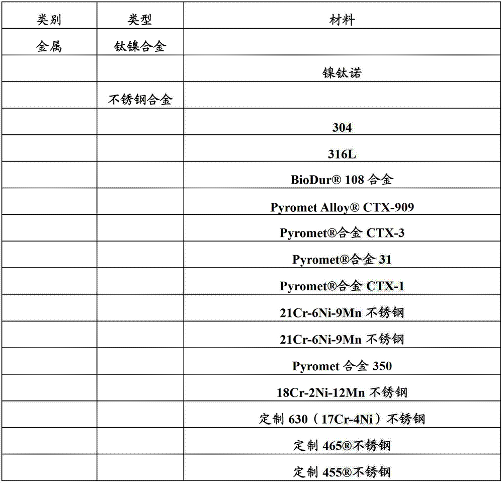
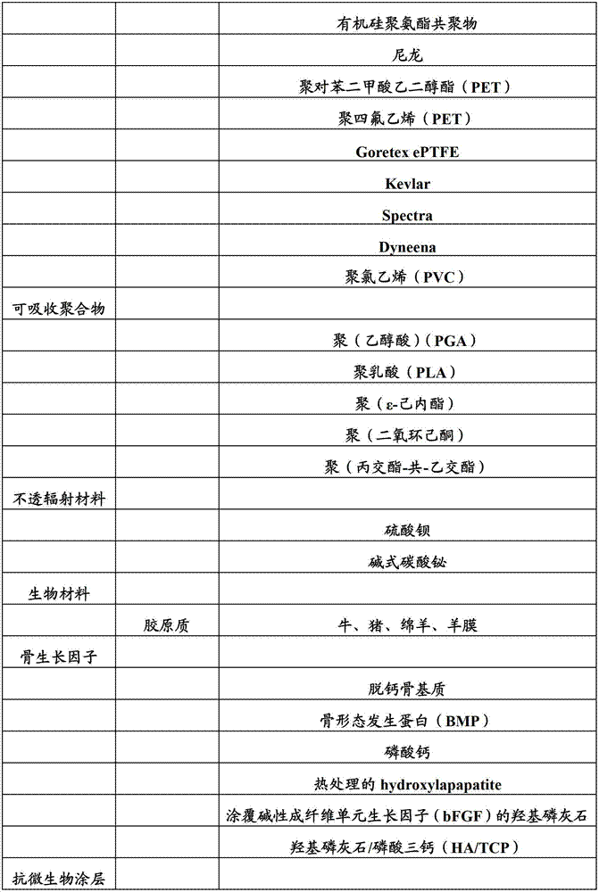
One or more surfaces of described device can be coated with the preparation that promotes growth in the bone.Described preparation can comprise hydroxyapatite behind calcium phosphate, the heat treatment, apply hydroxyapatite, hydroxyapatite/tricalcium phosphate (HA/TCP) and other suitable preparation of basic fibroblast unit somatomedin (bFGF), is included in one or more in listed those in the table 1.
One or more surfaces of described device can be coated with the preparation that suppresses or forbid growth in the bone.These surfaces can comprise impermeable material and other materials, for example one or more in listed those in table 1.
One or more surfaces of described device can be coated with can the eluting therapeutant preparation of medicine for example.
Described device and part thereof can comprise the material of any appropriate.Table 1 has been listed the exemplary materials that can be included in described device and the part thereof.
Table 1. material


Described device can be provided as tool set, and it can comprise one or more in structural support part, grappling substrate, central shaft member, anchor, delivery instrument and the related object.
Describe according to apparatus and method of the present invention in connection with accompanying drawing now.Accompanying drawing shows the example feature according to the apparatus and method of principle of the present invention.These features describe in the content of selected embodiment.Should be understood that a feature that illustrates in conjunction with the embodiments can be implemented according to principle of the present invention together with the feature shown in in conjunction with the embodiments another.
Apparatus and method as herein described are exemplary.Apparatus and method of the present invention can relate to some or all of step of some or all and/or illustrative methods in the feature of exemplary means.The step of described method can be carried out with the order different from order shown and described herein.Some embodiment can omit in conjunction with shown in the illustrative methods and described step.Some embodiment can comprise the step not shown and that do not describe in conjunction with illustrative methods.
Describe exemplary embodiment now with reference to accompanying drawing, accompanying drawing forms the part of embodiment.
In connection with the embodiment of exemplary bone implant and feature and associated hardware and utensil apparatus and method of the present invention are described now.Now with reference to accompanying drawing implant and associated hardware and utensil are described.Should be understood that, can utilize other embodiment and can carry out the modification of structure, function and process and do not depart from scope and spirit of the present invention.
Fig. 1 shows implant 100.Implant 100 can be implanted in the bone (not shown).Implant 100 along its longitudinal axes L I(wherein I represent implant) be elongated.Implant 100 can comprise outside extensible net 106.Implant 100 can comprise inner extensible net 108.Extensible net 106 can be stretched over the radial distance apart from LI.Extensible net 108 can be stretched over the radial distance apart from LI.
Extensible net 106 can extend to remote interface 110 from proximal base 130.(typically refer to being inserted into of device with respect to " far-end " of " near-end " and maybe will be inserted into leading section in the body).Extensible net 108 can extend to remote interface 120 from the proximal base (not shown).
Extensible net 106 can comprise the layout of unit 122.Extensible net 108 can comprise the layout of unit 124.The layout of unit 122 and/or unit 124 can and can comprise the layout that different flexible regions are provided for the layout of any appropriate.
The anchor that unit 122 can be configured to receive any appropriate is anchor 126 for example.The anchor that unit 124 can be configured to receive any appropriate is anchor 126 for example.Anchor 126 can be configured to penetrate extensible net 106 and/or extensible net 108.Anchor 126 can penetrate extensible net 106 and/or extensible net 108 at two or more position (not shown).
Fig. 2 illustrates the anatomical structure of fractured bones B.Implant for example implant 100 can be deployed in the inboard of bone B to repair bone B.
Bone B is illustrated as the radius that splits at crackle Fh and Fa place.Bone B comprises bone parts Pb, Ph and is arranged in the Pa of distal portion D.Bone section Pb is the largest portion of bone B.Bone section ph is the head part of bone B.Bone section Ph and Pa comprise articular surface AS.Bone parts Pb, Ph and Pa are along crackle Fa and Fh divides out or section ground divides separately.Crackle Fa crosses articular surface AS.Crackle Fh crosses the head of bone B.
To comprise that roughly the bone B of longitudinal axes L B comprises cortical bone BCO and spongy bone BCA shown in the cross section.Cortical bone BCO can have bone surface BS.The deployment of implant in the distal portion D of bone B can need to access the hole.The deployment of implant can need the displacement of spongy bone BCA.Inboard at bone B, implant can engage with spongy bone BCA.Implant can be fixed on the bone B with engaging of spongy bone BCA.
Bone B can be provided with the access hole H that is arranged in cortical bone BCO.Hole H can have hole wall HW.Hole wall HW can be for being used for the regulator for example shown in regulator 302(Fig. 3) be fixed to the position on the bone B.Hole H can have central axis C H.Axis T CH can be perpendicular to central axis C H.
Bone B can be provided with the access hole I that is arranged in cortical bone BCO.The device that inserts in the access hole I can need to pass the interior space IS displacement xI of marrow to arrive at the head part of bone B.Passing device that hole I inserts can need crooked to move through in the marrow space IS to arrive at the head part of bone B.
In the implant shown and described herein some can be disposed by hole H.In the implant shown and described herein some can be disposed by hole I.Be configured to by the implant that hole H disposes can comprise for implant hole H place or near be fixed to structure on the bone.Be configured to comprise be used to implant can being out of shape during bending and can stretching the structure of using to be used for operation by the implant that hole I disposes.Should be understood that implant can comprise the fixed structure that is suitable for accessing the hole, described implant will be deployed by described access hole, and will be also like this even described implant is illustrated as the fixed structure (for example regulator) with particular type at this paper.
Fig. 3 shows the implant 301 that is deployed in bone B inboard.Bone B can have to shown in bone B(Fig. 1) similar one or more structures.Implant 301 can have shown in Figure 1 to implant 100() similar one or more structures.The longitudinal axes L I of implant 100 can be corresponding to the central axis C H of hole H.
Fig. 4 shows along the view of the part of the implant 301 of 4-4 line (shown in Fig. 3) intercepting.Extensible net 106 can extend to far-end base portion 410 from proximal base 130.Far-end base portion 410 can comprise one or more in the structure of remote interface 110.Far-end base portion 410 can vertically be fixed on the parts 128.
By lock screw 112 fixing can be corresponding to the stretching, extension radius R O of extensible net 106 from longitudinal axes L I apart from xCB.By lock screw 112 fixing can be corresponding to the treatment radius R O of extensible net 106 apart from xCB.Therapeutic dose RO can reduce implant and act on tension force on the bone B.
Extensible net 108 can be along axis LI slip and/or around the angled displacement of axis LI after distance xCB is fixing.
Fig. 5 shows remote interface 110.Extensible net 106 can be fixed on the remote interface 110.Remote interface 110 can have one or more in the structure of the first far-end base portion 410.Remote interface 110 can be configured to extensible net 106 around the angular shift of axis LI.Remote interface 110 can longitudinally be fixed on the parts 128.Remote interface 110 can be rotatably fixed on the parts 128.
Fig. 6 shows another embodiment of remote interface 110.Big envelope member 504 can comprise the big envelope 602 that is configured to seal protuberance 606.Otch 604 can allow that extensible net 106 is around the angular range of axis LI motion.Extensible net 106 can be corresponding to the stretching, extension of extensible net 106 or folding around the angular movement of axis LI.
Fig. 7 A shows another embodiment of remote interface 110.Lid 502 can comprise for the otch 702 of extensible net 106 around the angular movement of axis LI.Extensible net 106 can be by end 704 restrictions of otch 702 around the angular movement of axis LI.Lid 502 can remain on protuberance 606 in the big envelope 504.Big envelope 504 and lid 502 can be configured to extensible net 106 folding around axis LI.
Fig. 7 B shows the sectional view of remote interface 110 and remote interface 120.Remote interface 110 can be configured to extensible net 108 and be stretched over angle η.Remote interface 120 can be configured to extensible net 108 and be stretched over angle ε.Angle ε can be greater than angle η.Remote interface 110 and remote interface 120 can be fixed extensible net along the translation of axis LI.Remote interface 110 and remote interface 120 can be allowed the rotation around axis LI.Remote interface 110 and remote interface 120 can be allowed the stretching, extension around axis LI.Remote interface 110 and remote interface 120 can be configured to provide the different stretching, extension radius (not shown) apart from axis LI.
Fig. 7 C shows the sectional view of remote interface 110 and remote interface 120.Remote interface 110 and remote interface 120 can be configured to extensible net 106 and extensible net 108 is folded in over each other.Remote interface 110 and remote interface 120 can be configured to that extensible net 106 is basically parallel to extensible net 108 in the folding position.
Fig. 8 shows the regulator 101 for implant 100.Regulator 101 can comprise slender member 103.Slender member 103 can comprise that anchor receives structure 802.Anchor receives structure 802 can be configured to receive anchor 114.Anchor 114 can be driven to shown in hole wall HW(Fig. 2) in.Anchor 114 can limit the along the longitudinal axially-movable of axis LI of slender member 103.
Fig. 9 shows exemplary regulator 902.Regulator 902 can comprise slender member 916.Regulator 902 can comprise slender member 906.Regulator 902 can comprise support plate 904.Slender member 906 can comprise extension 912.Support plate 904 can comprise extension 914.
Figure 10 shows exemplary regulator 1000.Regulator 1000 can comprise slender member 1004.Stablize 1000 and can comprise support plate 1006.Support plate 1006 can comprise that anchor receives structure 1008.Anchor receives structure 1008 can be configured to receive the interior anchor of surperficial BS that is driven to cortical bone BCO.
Figure 11 A shows exemplary implant 1100.Implant 1100 can comprise regulator 1101.Regulator 1101 can comprise slender member 1106.Slender member 1106 can comprise one or more in the structure of slender member 1004.Regulator 1101 can comprise support plate 1102.
Figure 11 B shows the example view of the regulator 1101 of the motion that is configured to limit slender member 1106.
Figure 12 shows exemplary regulator 1200.Regulator 1200 can comprise slender member 1212.Slender member 1212 can extend to support lantern ring 1202 from the implant (not shown).Slender member 1212 can be along shown in hole wall HW(Fig. 2) extend.Slender member 1212 can comprise longitudinal axis LEM.Longitudinal axes L EM can be basically parallel to the central axis C H of hole H and/or the longitudinal axis (not shown) of implant.Support lantern ring 1202 can be bearing in the access hole H(Fig. 2 shown in) opening part.Support lantern ring 1202 can comprise be basically parallel to shown in bone surface BS(Fig. 2) longitudinal axes L BC.
Figure 13 shows the exemplary regulator 1308 for implant 1312.Regulator 1308 can comprise slender member 1306.Regulator 1308 can comprise support lantern ring 1304.Support lantern ring 1304 can have longitudinal axes L BC.Longitudinal axes L BC can be basically parallel to shown in bone surface BS(Fig. 2).
Angle λ can be fixed by the lock screw (not shown) that is inserted in the hole 1316.Lock screw can be configured to fixed angle λ and implant 1312 from the stretching, extension (not shown) of longitudinal axes L I.Lock screw can comprise shown in lock screw 112(Fig. 1) structure in one or more.
Figure 14 shows the exemplary means 1400 for implant 1408.Device 1400 can comprise carriage 1406.Carriage 1406 can comprise that anchor receives structure 1404.Device 1400 can comprise extended element 1410.Extended element 1410 can be configured to carriage 1406 with respect to implant 1408 supportings.
Figure 15 shows the cross section of device 1400.Device 1400 can comprise stretching, extension lining 1504.Stretching lining 1504 can be for threadless.Extended element 1410 can comprise protuberance 1502.
The stretching, extension of protuberance 1502 can cause the friction between extended element 1410 and the carriage 1404.Friction between extended element 1401 and the carriage 1404 can disturb carriage 1404 with respect to the motion of implant 1408.Friction between extended element 1410 and the carriage 1404 can analog bracket 1404 with respect to the rotation of implant 1408 around axis LI.Friction between extended element 1410 and the carriage 1404 can analog bracket 1406 and implant 1408 between apart from xBI.
Figure 16 shows exemplary extended element 1410.Extended element 1410 can comprise protuberance 1502.Extended element 1410 can be rolled into cylindrical shape.In cylindrical configuration, edge 1604 can be close with edge 1602.
Figure 17 shows exemplary implant 301.Implant 301 can comprise extensible net 106 and extensible net 108.Extensible net 106 can coaxially be supported around implant component 128.Extensible net 108 can coaxially be supported around implant component 128.Extensible net 108 can be positioned at extensible net 106.
Extensible net 106 can comprise a plurality of unit 122.Unit 122 can be configured to engage with as shown in Figure 40 anchor.A plurality of unit 122 can comprise unit 122 density of any appropriate.Extensible net 106 can comprise unit 122 density that change along the longitudinal axes L I of implant 301.
Figure 18 shows the internal structure 1800 of implant 301.Internal structure 1800 can comprise extensible net 108.Extensible net 108 can comprise a plurality of unit 124.Unit 124 can be configured to engage with as shown in Figure 40 anchor.A plurality of unit 124 can comprise unit 124 density of any appropriate.Extensible net 108 can comprise unit 122 density that change along the longitudinal axes L I of implant 301.Extensible net 108 can be rotatably mounted around axis LI.
Figure 19 shows the cross section of exemplary implant 301.Extensible net 106 can comprise any suitable unit 122 density.Extensible net 106 can comprise along the longitudinal unit 122 density of axis LI variation, so that extensible netting gear has radius R O.
Extensible net 108 can comprise unit 124 density of any appropriate.Extensible net 108 can comprise along the longitudinal unit 124 density of axis LI variation, so that extensible netting gear has radius R I.Radius R I can comprise maximum RI.Difference between RO and the maximum RI can be corresponding to radial deflection 1902.Radial deflection 1902 can be configured to enough little, so that when extensible net 106 carrying radial load (not shown), extensible net 106 can be along radial deflection 1902 distortion to give this radial load transfer on the extensible net 108 that is positioned at maximum RI place.
Figure 20 shows the exemplary cut pattern 2000 for extensible net.Cutting pattern 2000 comprises distal portion 2018.Cutting pattern 2000 comprises close end 2020.Cutting pattern 2000 comprises edge 2010.Cutting pattern 2000 comprises edge 2012.
Cutting pattern 2000 can comprise zone 2002.Cutting pattern 2000 can comprise zone 2004.Cutting pattern 2000 can comprise zone 2006.Zone 2004 can comprise bent member 2014.Zone 2002 can comprise folding unit pattern 2016.Zone 2006 can comprise the folding unit pattern that has than zone 2002 large cell densities.
In " takeup type " configuration of axis LCP, zone 2004 bent member 2014 can be configured to have than restricted perpendicular to the axis T CP bending of axis LCP of the little opposing connection of the folding unit 2016 in zone 2002.
The increase of the density of folding unit pattern (for example unit pattern 2016) or reduce and corresponding to the restrictive increase of opposing connection axis TCP bending or to reduce.The increase of the angle between bent member (for example bent member 2014) and the folding unit pattern (for example the folding unit pattern 2016) or reduce and corresponding to the restrictive increase of bending or to reduce.
The warp architecture of cutting pattern 2000 can help to dispose implant based on cutting pattern 2000 by the hole (for example hole I) in the bone.
Figure 21 shows exemplary extensible implant 2100.Implant 2100 can comprise one or more in the structure of cutting pattern 2000.Z2 can be corresponding to the extended configuration in the zone 2002 of cutting pattern 2000.Z1 can be corresponding to the extended configuration in the zone 2004 of cutting pattern 2000.Z3 can be corresponding to the extended configuration in the zone 2006 of cutting pattern 2000.
Under extended configuration, the bent member of Z1 can provide axial rigidity to implant 2100.Under the effect of the axial compression of axis LI, the bent member of Z1 can superpose and further limit along the compression of axis LI each other.Under compressive state, the bent member of Z1 can be conducive to by the hole for example hole I dispose implant.
Figure 22 shows exemplary cut pattern 2200.Cutting pattern 2200 can be around longitudinal axes L CP " coiling " to form extensible net (for example being positioned at the extensible net 106 and/or 108 under the folded state).In order to realize " takeup type " configuration, cutting pattern 2200 can be cut into cylindrical tube.
Cutting pattern 2200 can comprise zone 2202.Cutting pattern 2200 can comprise zone 2204.Zone 2202 can comprise and regional 2204 different cell densities.The cell density in zone can be configured to improve and the engaging of anchor.
In " takeup type " configuration of axis LCP, bent member 2206 can have than crooked restricted perpendicular to the axis T CP of longitudinal axes L CP of the little opposing connection of unit pattern 2208.The increase of the length of the shank of bent member 2218 or reduce and corresponding to the crooked restrictive increase of opposing connection axis TCP or to reduce.The increase of the angle between the shank 2218 of bent member or reduce and corresponding to the crooked restrictive increase of opposing connection axis TCP or to reduce.
Under extended configuration, bent member 2206 can provide axial rigidity to implant.Under the effect of the axial compression of LCP, the shank 2218 of bent member can fold around the top, and restriction is along the further compression of axis LCP.Bent member 2206 can be conducive to by the hole for example hole I dispose implant.
Figure 23 A shows exemplary cut pattern 2300.Cutting pattern 2300 can comprise folding unit pattern 2302.Cutting pattern 2300 can comprise support unit 2306.Cutting pattern 2300 can comprise support unit 2304.
Cutting pattern 2300 can flatly be laid in the plane P.Cutting pattern 2300 can be configured to around longitudinal axes L CP " coiling ", so that edge 2308 is adjacent with edge 2310.
In order to realize " takeup type " configuration, cutting pattern 2300 can cut into cylindrical tube.Longitudinal axes L CP can be corresponding to the longitudinal axis of implant, for example the longitudinal axes L I of implant 100.
In " takeup type " configuration, cutting pattern 2300 can be configured to around axis LCP stretching, extension and/or folding.The width xSM of support unit 2304 and the width xSM of holding components 2306 can be configured to perpendicular to plane P.The width xSM of support unit 2304 and the width xSM of holding components 2306 can be configured to be parallel to plane P.
When width xSM was configured to be arranged in the plane P and/or is parallel to plane P, support unit 2303 and support unit 2306 can have than around crooked restricted around axis T1 of axis T2 crooked restricted large.When width xSM was configured to perpendicular to plane P, support unit 2304 and support unit 2306 can be configured to crooked restricted greater than around axis T1 around axis T2 crooked restricted.
When the implant based on cutting pattern 2300 is passed through shown in the H(Fig. 2 of hole) when inserting in the bone B, width xSM can be configured to be arranged in the plane P and/or be parallel to plane P.When based on the implant of cutting pattern 2300 in marrow shown in space IS(Fig. 2) during medial expansion, width xSM can be configured to perpendicular to plane P.
Supporting member 2304 can be configured to be independent of supporting member 2306 with respect to Plane Rotation.Supporting member 2306 can be configured to be independent of supporting member 2304 with respect to Plane Rotation.In a configuration, supporting member 2304 and can be arranged in the plane P and/or be parallel to plane P, and supporting member 2306 can be perpendicular to plane P.
Figure 23 B shows exemplary extensible implant 2322.Exemplary implant 2322 can comprise uses cutting pattern 2300 or any suitable cutting pattern.Implant 2322 can comprise longitudinal axes L I.Implant 2322 can comprise inner extensible net 2316.Implant 2322 can comprise outside extensible net 2320.Implant 2322 can comprise interior support member 2314.Supporting member 2314 can limit the plane, and this plane comprises LI and perpendicular to the axis T 2 of LI.
Axis T2 is perpendicular to LI and perpendicular to the plane that is limited by T1 and LO.Supporting member 2314 can be around axis T1 than more flexible around axis L1.
Supporting member 2314 can comprise that anchor receives structure 2324.Anchor receives structure can be configured to receive anchor 2318.Supporting member 2314 can comprise that anchor receives structure 2326.Anchor receives structure 2326 can be configured to receive anchor 2314. Anchor 2314 and 2316 can be driven along the direction that is basically parallel to the plane that is limited by LI and T2.
For example, multilamellar implant (for example implant 2322) can be orientated a kind of configuration in the folding configuration.The layer of implant 2322 can relative to each other rotate when these layers stretch or be implanted in the bone.The relative rotation of the layer of implant 2322 can be provided at the flexibility in the plane in folding, but under implanting state and/or extended configuration in the plane is rigidity.Implant the layer relative rotation can be conducive to insert implant in the bone and/or by radial path with in the implant implantable bone.The relative rotation of the layer of implant can be conducive to insert implant in the bone and/or pass through hole (for example hole I) with in the implant implantable bone.
Figure 24 A shows exemplary cut pattern 2400.Cutting pattern 2400 can comprise structural elements 2410.Cutting pattern 2400 can comprise lateral support member 2402.Cutting pattern 2400 can comprise lateral support member 2404.Lateral support member 2404 can comprise joint 2408.Lateral support member 2402 can comprise joint 2406.
Cutting pattern 2400 can be configured to and can stretch along axis E CP.Cutting pattern 2400 can be folding along axis E CP.Cutting pattern 2400 can be around axis LCP " coiling ".In " takeup type configuration ", cutting pattern 2400 can be around axis LCP stretching, extension and/or folding.In order to realize " takeup type configuration ", cutting pattern 2400 can cut into cylindrical tube.
Figure 24 B shows exemplary implant 2412.Implant 2412 can comprise structural elements 2418.Implant 2412 can comprise structural elements 2420.Implant 2412 can comprise lateral support member 2414.Implant 2412 can comprise lateral support member 2416.Figure 24 B shows the lateral support member 2414 and 2416 between folded state and deployed condition.
Figure 25 shows exemplary extensible implant component 2500.Implant component 2500 can comprise lateral support member 2402.Implant component 2500 can comprise lateral support member 2404.Implant component 2500 can comprise structural elements 2410.Figure 25 shows the lateral support member 2402 that is arranged in solderless wrapped connection 2406 configuration that launch.Figure 25 shows the lateral support member 2404 that is arranged in solderless wrapped connection 2408 configuration that launch.In deployed configuration, lateral support member 2402 and/or 2404 can be configured to be provided for implant component 2500 around the radial support of longitudinal axes L IC.
Figure 26 shows implant component 2500 along the view of line 5-5.Figure 25 shows the implant component 2500 that is positioned under the extended configuration of axis LIC.Lateral support member 2402 can be configured to limit implant component 2500 from the circumferentially extending R1 of axis LEW.Structure member 2404 can be configured to limit implant component 2500 from the circumferentially extending R2 of axis LIC.To the restriction of the stretching, extension of parts 2500 can limiting structure supporting member 2410 " flexing ", thereby increase the axial rigidity of parts 2500.
Figure 27 shows exemplary cut pattern 2700.Cutting pattern can be for around longitudinal axis (not shown) " coiling ", so that edge 2712 is configured to is adjacent with edge 2714.In " takeup type " configuration, cutting pattern 2700 can stretch from longitudinal axis.
Cutting pattern 2700 can comprise cell density 2702, and cell density 2702 vertically changes when the longitudinal axis of implant stretches in section's section 2701.Cutting pattern 2700 can comprise cell density 2704, and cell density 2704 vertically changes when longitudinal axis stretches in section's section 2702.Cutting pattern 2700 can comprise cell density 2706, and cell density 2706 vertically changes when the longitudinal axis of implant stretches in section's section 2703.Cutting pattern 2700 can comprise cell density 2708, and cell density 2708 vertically changes when the longitudinal axis of implant stretches in section's section 2704.Cutting pattern 2700 can comprise cell density 2710, and cell density 2710 vertically changes when the longitudinal axis of implant stretches in section's section 2705.
In order to realize " takeup type " configuration, cutting pattern 2700 can be cut into cylindrical tube.
Figure 29 shows exemplary extensible implant 2900.Implant 2900 can be configured to be stretched to " umbrella " shape.Exemplary implant 2900 can comprise close end 2902 and distal portion 2904.Distal portion 2904 can have the stretching, extension radius larger than the stretching, extension radius of close end 2902.Extensible implant 2900 can be based on single extensible net.
Larger stretching, extension radius can support the fracture segment of bone B.Larger stretching, extension radius can support the not fracture end of bone B.Implant 2900 can partially or completely be filled the marrow space IS that is positioned at bone B inboard.Implant 2900 can not contain in the remote end part of bone B space IS in marrow in the situation of enough spongy bone BCA to be used.
Figure 30 shows exemplary extensible implant 3000.Implant 3000 can be configured to be extended into " top medicated cap " shape.Exemplary implant 3000 can comprise proximal structure 3002 and distal end members 3004.Distal end members 3004 can have the stretching, extension radius larger than the stretching, extension radius of proximal structure 3002.Implant 3000 can comprise one or more in the structure of implant 2900.
Figure 31 A shows exemplary implant 3130.Implant 3130 can comprise longitudinal axes L I, remote interface 110 and local interface 110.Implant 3130 can be configured to be extended into spheric profile or " lollipop " shape.Anchor (for example shown in anchor 126(Fig. 1)) can easily engage and not be deflected with implant 3130.
Figure 31 B shows exemplary cut pattern 3138.Cutting pattern 3130 can be configured to be extended into " lollipop " shape (shown in Figure 31 A).
Figure 31 C shows exemplary cut pattern 3100.Cutting pattern 3100 can be around longitudinal axis (not shown) " coiling ", so that edge 3118 is configured to is adjacent with edge 3116.In " takeup type " configuration, cutting pattern 3100 can stretch from longitudinal axis.In order to obtain " takeup type " configuration, cutting pattern 3100 can be cut into cylindrical tube.
Cutting pattern 3100 can comprise vertical cell density 3102.Cutting pattern 3100 can comprise vertical cell density 3104.Cutting pattern 3100 can comprise vertical cell density 3106.
Cutting pattern 3100 can be configured to and can be extended into the profile that can comprise rectangle, rhombus, triangle, ellipse, circle and/or asymmetric shape around the longitudinal axis (not shown).Cutting pattern 3100 can be extended into the profile with cross section around the longitudinal axis (not shown), and wherein cross section can comprise rectangle, rhombus, triangle, ellipse, circle and/or asymmetric cross sectional shape.
Figure 32 shows implant 3200.Implant 3200 can comprise longitudinal axes L I.Implant 3200 can comprise can be around the extensible net 3210 of axis LI stretching, extension.Implant 3200 can comprise can be around the extensible net 3208 of axis LI stretching, extension.Extensible net 3210 can be in the outside of extensible net 3208.
Extensible net 3210 can be configured to be extended into profile 3202 around axis LI.Profile 3202 can be for conical shaped.Extensible net 3210 can be configured to be extended into profile 3206 around axis LI.Profile 3206 can for general plane and be basically perpendicular to longitudinal axes L I.Profile 3204 can be configured to around axis LI stretching, extension and be connected between profile 3202 and the profile 3206.
Figure 33 shows exemplary implant 3300.Implant 3300 can comprise supporting member 3302.Supporting member 3302 can extend to from the close end 3306 of implant 3300 distal portion 3308 of implant 3300.Implant 3300 can comprise bone engagement member 3304.Bone engagement member 3304 can from the close end 3306 of implant 3300 alongside supporting member 3302 extend a length 3312.Bone engagement member 3304 can be from supporting member 3302 length 3314 of scattering out.Bone engagement member 3304 can be from supporting member 3302 with angle
Scatter.
Top 3310 can be configured to shown in bone B(Fig. 2) spongy bone BCA engage.The translation that bone engagement member 3304 can be configured to limit between implant 3300 and the bone B is moved.Bone engagement member 3304 can be configured to limit rotatablely moving between implant 3300 and the bone B.
Figure 34 shows the view from close end 3306 of implant 3300.Bone engagement member 3304 can be configured to extend to supporting member alongside 3302 along the direction on the surface that is basically perpendicular to supporting member 3302.Bone engagement member 3304 can be configured to provide along the axially mounting of the longitudinal axis (not shown) of implant 3300 to implant 3300.Bone engagement member 3304 can be configured to provide radial support around the longitudinal axis (not shown) of implant 3300 to implant 3300.
The angle [alpha] that forms between bone engagement member 3304 and supporting member 3302 can be 90 degree roughly.Bone engagement member 3304 and supporting member 3302 can form " L " shape, " U " shape or any other suitable shapes.
Figure 35 shows exemplary implant 3500.Implant 3500 can comprise net 3504.Implant 3500 can comprise supporting structure 3502.Implant 3500 can comprise bone engagement member 3506.Bone engagement member 3506 can pass net 3504.Bone engagement member 3506 can pass net 3504 with the angle μ between net 3504 and bone engagement member 3506.
Top 3508 can be with shown in bone B(Fig. 2) spongy bone BCA engage.The translation that bone engagement member 3506 can be configured to limit between implant 3500 and the bone B is moved.Bone engagement member 3506 can be configured to limit the rotary moving between implant 3500 and the bone B.
Figure 36 shows the distal end view of exemplary implant 3500.One or more bone engagement members 3505 can be configured to engage with spongy bone BCA.One or more bone engagement member 3506 is passable.
Figure 37 shows and is positioned at shown in bone B(Fig. 2) inboard exemplary extensible implant 3700.Bone B is depicted as has crackle Fh and Fa.Implant 3700 can be configured to repair crack Fh and Fa.Anchor 3702 and 3704 can be configured to bone parts Pa and Ph are fixed on the implant 3700.
Figure 38 shows exemplary implant 3800.Implant 3800 can comprise extensible net 3804.Implant 3800 can comprise scissor locking mechanism 3802.Locking mechanism 3802 can be arranged on the remote end part of implant 3800.Locking mechanism 3802 can dispose to stretch.Locking mechanism 3802 can be configured to fold.Locking mechanism 3802 can be configured to by stretching around the rotation of pivot axis P D and/or folding.
Figure 39 shows exemplary implant 3900.Implant 3900 can comprise extensible net 3804.Implant 3900 can comprise scissor locking mechanism 3806.Implant 3900 can comprise scissor locking mechanism 3902.
Figure 40 shows exemplary net 4000.Net 4000 can represent in conjunction with the net that uses shown in this paper and in the described implant.For example, net (for example net 4000) can be included in shown in implant 100(Fig. 1), shown in implant 300(Fig. 3), shown in implant 1312(Figure 13), shown in implant 2100(Figure 21), shown in implant 2320(Figure 23 b), shown in implant 2900(Figure 29), shown in implant 3000(Figure 30), shown in implant 3130(Figure 31 a), shown in implant 3200(Figure 32), shown in implant 3500(Figure 35), shown in implant 3804(Figure 38) and arbitrarily in other suitable implants.
Net 4000 can comprise for example unit 4002, one or more unit.Net 4000 can comprise front 4010 and the back side 4012.Unit 4002 is configured to receive anchor 4004.Anchor 4004 can have to such as anchor 114,116 with shown in 126(Fig. 1), shown in 1204(Figure 12), shown in 1314(Figure 13) anchor one or more structures similar with any other suitable anchors.Anchor 4004 can be configured to the sliver of bone B is fixed on the net 4000.
Figure 41 shows exemplary screw thread anchor 4100.Screw thread anchor 4100 can be configured to tension force is applied between the crackle and net 4000 of bone B.Screw thread anchor 4100 can be configured to engage with unit 4002 based on the tolerance of screw thread anchor 4100.Screw thread anchor 4100 can comprise root 4102.Screw thread anchor 4100 can comprise bizet 4104.
The tolerance of screw thread anchor 4100 can comprise major diameter D
Greatly, minor diameter D
Little, average diameter D
On average, angle of rifling σ, pitch δ.How much tension force is the tolerance of screw thread anchor 4100 can be applied to unit (for example the unit 4002) based on and upward be selected.
Figure 42 (A)-Figure 42 (C) shows exemplary screw thread anchor 4230,4220 and 4200. Anchor 4230,4220 and 4200 can comprise one or more in the tolerance of screw thread anchor 4100.Anchor 4230 comprises head part 4234.Head part 4234 can comprise axis 4232.Anchor 4220 comprises head part 4224.Head part 4224 can comprise axis 4222.Anchor 4200 comprises head part 4204.Head part 4204 can comprise axis 4202.
Figure 43 shows exemplary skeleton S.Skeleton S comprises exemplary bone Si, wherein can be as in conjunction with shown in bone B(Fig. 2 in exemplary implant described herein) mode that illustrates and describe uses.Table 2 comprises the part tabulation of bone Si.
Table 2. bone Si
| Bone | Reference numeral in Fig. 2 |
| The far-end radius | S 0 |
| Humerus | S 1 |
| Near-end radius and ulna (elbow) | S 2 |
| Metacarpal bone | S 3 |
| Clavicle | S 4 |
| Rib | S 5 |
| Vertebra | S 6 |
| Ulna | S 7 |
| Hipbone | S 8 |
| Femur | S 9 |
| Tibia | S 10 |
| Fibula | S 11 |
| Metatarsal | S 12 |
Figure 44 has schematically shown shown in bone B(Fig. 2) anatomical structure.The anatomical structure of bone B is listed in table 2.Can relate to one or more in the anatomical structure shown in the table 3 according to the apparatus and method of principle of the present invention.The structure of bone B can with reference to axis of bone line LB(wherein B represent bone) and radius R B((wherein B represent bone) be described.
Table 3. can be by the anatomical structure in some bone types of apparatus and method treatment
| Anatomical structure | Reference numeral in Figure 44 |
| Articular surface | B 0 |
| Spongy bone, spongy bone or bone trabecula | B 1 |
| Pulp cavity | B 2 |
| Cortical bone or high density bone | B 3 |
| Periosteum | B 4 |
| The near-end articular surface | B 5 |
| Backbone or stage casing | B 6 |
| Metaphysis or end regions | B 7 |
| Epiphysis | B 8 |
| Articular surface | B 9 |
Term " end bone " and " end bone fracture " can be used to refer to the fracture that generation occurs in the epiphysis of long bone or metaphyseal region.These fracture comprise periarticular and intra-articular fracture.
Figure 45 shows the exemplary conductor 4500 of locating be used to the position H ' that is arranged on the bone B.Exemplary utensil conductor 4500 can be configured to bone B preparation is used for the conveying of exemplary implant as herein described.Broaching tool head 4524 can be transported to by conductor 4500 the target zone R of space IS in the marrow
tIn.Target zone R
tBe illustrated as and be positioned at spongy bone B
CAIn, but also can be positioned at spongy bone B
CAWith cortical bone B
COAny in or two in.Sidepiece template 4530 and top template 4532 can be in alignment with guide wires 4520.Arm 4531 can supporting template 4530.The implementer can arrange template 4530 and 4532, so that template 4530 and 4532 " projection " is to target zone R
tOn, so that conductor 4500 is directed to target zone R with broaching tool head 4524
tIn.
Template 4530 can comprise blade profile 4534 and the arbor wheel exterior feature 4536 for the position of " inswept " zone of difference projection broaching tool head 4524 and axle shape structure 4525.Template 4532 can comprise blade profile 4538 and the arbor wheel exterior feature 4540 for the target position of target " inswept " zone of difference projection broaching tool head 4524 and axle shape structure 4525.Template 4530 and 4532 can be configured to the shape of any appropriate apparatus that projection can be deployed, for example drilling tool, the saw of coring, prosthetic appliance or arbitrarily other suitable apparatuses.
Fluorescence imaging can be used for template 4530 and 4532 with respect to target zone R
tThe location.
Broaching tool head 4524 can rotate to remove the intramedullary bone material, so that prosthetic appliance can be implanted among the IS of space in marrow.Broaching tool head 4524 can drive and supporting by broaching tool control part 4526 and broaching tool sheath cover 4527.
Conductor 4500 can comprise base portion 4502.Alignment members 4504 and 4506 can be extended with the conductor centre line C L with conductor 4500 from base portion 4502
GBone centre line C L with the top surface of bone B
BSAim at.In the alignment members 4504 and 4506 one or two can be for elastic.In the alignment members 4504 and 4506 one or two can be for rigidity.
Alignment members 4504 is not shown with 4506() can relatively along the surface of bone B freely slide.Conductor 4500 can comprise can be along centre line C L
BSThe contact site 4508 and 4510 that engages with bone B.Contact site 4508 and 4510 can extend from the basal surface (not shown) of conductor 4500.Contact site 4508 and 4510 can prevent the conductor centre line C L
GRotate to be and the bone centre line C L
BSMisalignment.
Contact site 4508 and 4510 can guarantee that conductor 4500 aims at the surface of bone B, even this is owing to two contact points can be to be stable on uneven surface in the unsettled situation at 3,4 or more contact site.
Conductor 4500 can comprise that horizontal clamping plate 4512 and 4514(are not shown).Laterally clamping plate 4512 and 4514 can engage with the surface of bone B to prevent that conductor 4500 is around the conductor centre line C L
GRotate along direction θ.Laterally clamping plate 4512 and 4514 can be for elastic to allow some slips on bone B.
When the implementer was arranged on bone B when upper with conductor 4500, alignment members 4504 and 4506 first components that can engage with bone B for conductor 4500.Alignment members 4504 and 4506 can contact site 4508 and 4510 and clamping plate 4512 and 4514 with before bone B engages with the conductor centre line C L
GBring to and the bone centre line C L
BSAim at.Subsequently, in certain embodiments, clamping plate 4512 and 4514 can engage with bone B to suppress the rotation along direction θ.Subsequently, in certain embodiments, contact site 4508 and 4510 can be along the bone centre line C L
BSB engages with bone.Contact site 4508 and 4510 can have sharp keen to provide the conductor centre line C L
GWith the bone centre line C L
BSGo the further restriction of aiming at.In certain embodiments, may exist no more than two contact sites (for example, 4508 and 4510) to guarantee contact site and bone centre line C L
BSIn a straight line.
Conductor 4500 can comprise handle dried 4516 and grip part 4518.The implementer can manually catch grip part 4518.In certain embodiments, the torque limiter (not shown) can be configured to limit the implementer and can be applied to moment of torsion on contact site 4508 and 4510 via grip part 4518.
Guide wire 4520 can receive and guide the utensil of any appropriate.Guide wire 4520 can be orientated about handle 4516 angled α.In certain embodiments, angle [alpha] can be for fixing.In certain embodiments, angle [alpha] can be for adjustable.In certain embodiments, template 4530 and 4532 can be fixing with respect to guide wire 4520.In certain embodiments, comprise wherein α be more adjustable embodiment and wherein α be more uncontrollable embodiment, guide wire 4520 can be orientated so that the axis L of guide wire 4520
GTDoing 4516 axis L with handle
HEssentially identical position and bone B intersect.Grip part 4518 will be set directly at thus position, hole H ' in the heart.
Conductor 4500 can comprise that passage 4542 and 4544(are not shown).Bar 4546 and 4548 can insert by passage 4542 and 4544 respectively and pass cortical bone B
COBar 4546 and 4548 can be stabilized in conductor on the bone B.Bar 4546 and 4548 can be the Ji Shi steel wire.Bar 4546 and 4548 can use silk thread to bore and insert.
Apparatus and method as herein described are exemplary.Apparatus and method of the present invention can relate to some or all in the step of some or all and/or illustrative methods in the structure of exemplary means.The step of described method can be carried out with the order different from order shown and described herein.Some embodiments of the present invention can be omitted the step that illustrates and describe in conjunction with illustrative methods.Some embodiments of the present invention can comprise the step not shown and that do not describe in conjunction with illustrative methods.
Although described the present invention with regard to specific embodiment and application, those skilled in the art can generate other embodiment and modification in view of this instruction and not deviate from the spirit of principle of the present invention or exceed the scope of principle of the present invention.Therefore, should be understood that the accompanying drawing of this paper and explanation are used as example and provide to be conducive to understanding of the present invention and should not be construed as limiting the scope of the invention.
Therefore, the apparatus and method that are used for fracture repair are provided.Those skilled in the art should be understood that the present invention can be by the embodiment practice different from described embodiment, and described embodiment is provided for illustrative and nonrestrictive purpose.The present invention is only by following claim restriction.
Claims (162)
1. device that is used for bone implant, the bone implant parts that described implant has the first base portion and the second base portion and extends between described the first base portion and the second base portion, described the first base portion and described the second base portion limit longitudinal axis, described bone implant parts according to described the first base portion and described the second base portion along the relative shift of described axis and with respect to described longitudinal axis deflection, described device comprises:
The first noumenon, described the first noumenon and described axis are substantially coaxial and vertically be fixed on described the first base portion;
The second body, described the second body and described axis are substantially coaxial and vertically be fixed on described the second base portion; And
Elongated engagement member, described elongated engagement member are configured to longitudinally fix the distance between described the first noumenon and described the second body.
2. device as claimed in claim 1, wherein:
Described distance comprises:
The maximum corresponding with the complete folded state of described implant; And
The minima corresponding with the full extension state of described implant;
The distance of the arbitrary value described elongated engagement member also is configured to be vertically fixed in from about described maximum to the scope of about described minima;
Described complete folded state is configured to pass the state in the access hole in the described bone corresponding to wherein said implant; And
Described full extension state is corresponding to wherein said implant state in described bone lateral expansion under standard temperature and pressure (STP).
3. device as claimed in claim 1, wherein, described distance is controlled the stretching, extension of described implant by the length of controlling described implant.
4. device as claimed in claim 1, wherein, described distance is corresponding to the treatment length of described bone implant.
5. device as claimed in claim 1, wherein, described distance is corresponding to the treatment radius of described bone implant.
6. device as claimed in claim 1, wherein:
Described slender member is the integral type configuration;
For being configured to all structures operated in conjunction with described implant, described elongated engagement member is configured to separately fixing described distance.
7. device as claimed in claim 1, wherein, described distance is corresponding to the extended configuration of described bone implant, and described extended configuration provides for the structure support of bone and elimination and acts on remnants pressure radially outward on the inwall of described bone.
8. device as claimed in claim 1, wherein, described elongated engagement member is configured to tension force is applied between described the first noumenon and described the second body.
9. device as claimed in claim 6, wherein:
Described slender member is the integral type configuration; And
For being configured to all structures operated in conjunction with described implant, described elongated engagement member is configured to separately apply described tension force.
10. device as claimed in claim 9, wherein, when described slender member fixing described apart from the time, described slender member engages with described the first noumenon and engages with described the second body in described the second body interior in that described the first noumenon is inner.
11. device as claimed in claim 10, wherein:
Described the first noumenon comprises the first threaded sleeve;
Described the second body comprises the second threaded sleeve; And
Described slender member comprises and is configured to the threaded portion that engages with described the first threaded sleeve and described the second threaded sleeve.
12. device as claimed in claim 11, wherein, described threaded portion is enough carefully to avoid significantly changing described distance when engaging with described the second threaded sleeve after described the first threaded sleeve engages when described threaded portion.
13. device as claimed in claim 1, wherein, when described the second body had external diameter, described the first noumenon comprised the cylindrical shape part that internal diameter is larger than the described external diameter of described the second body, and described cylindrical part is divided a part that is configured to receive described the second body.
14. device as claimed in claim 1, wherein, support extends between described the first base portion and described the second base portion, and described support comprises described bone implant parts and is configured to support bone.
15. device as claimed in claim 14, wherein, when described the first base portion when described the second base portion moves, described support stretches away from described longitudinal axis.
16. device as claimed in claim 15, wherein, described implant comprises the grappling substrate that is arranged between described longitudinal axis and the described support.
17. device as claimed in claim 1, wherein, the grappling substrate is extended between described first and second base portion, and described grappling substrate comprises described bone implant parts and is configured to support bone.
18. device as claimed in claim 17, wherein, when described the first base portion when described the second base portion moves, described grappling substrate is stretched away from described longitudinal axis.
19. device as claimed in claim 17, wherein, described implant comprises support, and described support is positioned at larger radial distance with respect to described longitudinal axis than described grappling substrate.
20. device as claimed in claim 19, wherein:
Protuberance one or two extension from described the first base portion and described support;
Pouch is arranged in described the first base portion and the described support one or two;
Described protuberance is biased, so that it engages with described pouch; And
Described support is basic with engaging of described pouch vertically and be rotatably fixed on described the first base portion by described protuberance.
21. device as claimed in claim 20, wherein, when described distance is fixedly the time, described grappling substrate can be slided and can be around described longitudinal axis angular displacement along described longitudinal axis.
22. one kind is used for the control bone implant in the method for the stretching, extension diameter of bone inboard, described method comprises:
Length by the fixing described implant of distance control between the first base portion and the second base portion, described the first and second base portions use the slender member that extends between described the first base portion and described the second base portion, described the first and second base portions are to be conllinear substantially; And
The closed described slender member that is positioned at described bone inboard by closure access hole, described implant is transported in the described bone by described access hole.
23. method as claimed in claim 22, also comprise, when described implant has complete folded state and full extension state, described complete folded state is configured to pass the state in the access hole that is arranged in described bone corresponding to wherein said implant, described full extension state is fixed on following value corresponding to wherein said implant state in described bone lateral expansion under standard temperature and pressure (STP) with described distance:
Be not more than the maximum corresponding with the described complete folded state of described implant; And be not less than the minima corresponding with the described full extension state of described implant.
24. interface that is used for extensible bone implant, described implant has central shaft member and supporting member, described supporting member has first end and the second end that is spaced apart from each other along described central shaft member, described supporting member has intermediate section, described intermediate section when described implant stretches away from the radial deflection of described central shaft member, described interface comprises the supporting member terminal, and described supporting member terminal configuration is:
Between the extensin period of described implant that described the second end is vertically fixing with respect to described central shaft member; And
Between described extensin period that described the second end is radially fixing with respect to described central shaft member;
Wherein, described supporting member terminal comprises the gap otch for described supporting member, so that described the second end has range of angular motion between described extensin period.
25. interface as claimed in claim 24, wherein, when described the second end comprised protuberance, described supporting member terminal also comprised the big envelope that is configured to seal described protuberance;
Wherein, described otch crosses described big envelope.
26. interface as claimed in claim 25, wherein, described big envelope comprises:
The first big envelope member; And
The second big envelope member, described the second big envelope member are configured to separate that with described the first big envelope member described protuberance is introduced in the described big envelope.
27. interface as claimed in claim 26, wherein, described the first big envelope member comprises the stop surfaces that limits described range of angular motion.
28. interface as claimed in claim 27, wherein, described stop surfaces comprises the end of described otch.
29. interface as claimed in claim 26, wherein, described the second big envelope member comprises the stop surfaces that limits described range of angular motion.
30. interface as claimed in claim 24, wherein, described supporting member terminal configuration is around described central shaft member rotation.
31. interface as claimed in claim 24, wherein, described supporting member terminal is rotatably fixing with respect to described central shaft member.
32. a regulator that is used for bone implant, described bone has the access hole for delivery of described implant, and described access hole has hole wall, and described regulator comprises slender member, and described slender member is configured to when described implant is deployed in the described bone:
Extend along described hole, and
Between described implant, extend;
And anchor receives structure;
Wherein, described anchor receives structure and is configured to receive the anchor that is driven in the described hole wall.
33. regulator as claimed in claim 32, wherein, described slender member comprises that extending beyond described anchor receives structure and be configured to the extension hinged with support plate.
34. regulator as claimed in claim 33, wherein:
Described extension comprises the first surface around the periphery of described anchor receiving member; And described support plate comprises the second surface with described first surface complementation.
35. regulator as claimed in claim 34, wherein, the pull strength that comes from the anchor that is received by described anchor reception structure is configured to make described second surface to bear against described first surface.
36. regulator as claimed in claim 32, wherein, in the time of in described anchor is driven into described hole wall, described slender member is configured to limit the rotation of described implant.
37. regulator as claimed in claim 32, wherein, in the time of in described anchor is driven into described hole wall, described slender member is configured to limit described implant moving along the longitudinal axis of described implant.
38. regulator as claimed in claim 32, wherein, in the time of in described anchor is driven to described hole wall, described regulator is configured to restriction:
The rotation of described slender member in described hole; And
Described slender member is along the axially-movable in described hole.
39. regulator as claimed in claim 32, wherein:
Described implant comprises the locking mechanism be used to the shape of keeping described implant;
Described locking mechanism is configured to by the screw locking of inserting in the described access hole; And
Described screw is adjustable after described anchor reception structure has received described anchor.
40. regulator as claimed in claim 32 also comprises support plate, described support plate anchors on the described bone and is basically parallel to the longitudinal axis setting of described bone;
Wherein, described support plate is configured to limit the rotation of described slender member in described hole.
41. regulator as claimed in claim 32 also comprises support plate, described support plate is configured to:
Anchor on the described bone;
Be basically parallel to the longitudinal axis setting of described bone; And
Limit described slender member along the axially-movable in described hole.
42. regulator as claimed in claim 32 also comprises support plate, described support plate is configured to:
Anchor on the described bone;
Be basically parallel to the longitudinal axis setting of described bone;
Limit the rotation of described slender member in described hole; And
Limit described slender member along the axially-movable in described hole.
43. it is that the first anchor receives structure that regulator as claimed in claim 42, described anchor receive structure, wherein, described support plate also comprises the second anchor reception structure that is configured to receive described anchor.
44. regulator as claimed in claim 43, wherein, described support plate comprises that also the 3rd anchor of the anchor in the outer surface that is configured to receive the cortical wall that is driven to described bone receives structure.
45. it is that the first anchor receives structure that regulator as claimed in claim 32, described anchor receive structure, described regulator also comprises:
Receive the first adjacent edge of structure with described the first anchor;
Receive the second adjacent edge of structure with described the first anchor;
Support plate, described support plate comprise the second anchor reception structure that is configured to receive described anchor;
Wherein:
Described the first edge and the described second edge limited pivot axis;
Described anchor be configured to described support plate be fixed as with the contact of described bone photo and be fixed on the substantially parallel position of the outer surface of described bone in; And
Described support plate is configured to limit the rotation of described slender member in described hole.
46. regulator as claimed in claim 32 also comprises:
Receive the first adjacent edge of structure with described anchor;
Receive the second adjacent edge of structure with described anchor;
Support plate, described support plate comprise the second anchor reception structure that is configured to receive described anchor;
Wherein:
Described the first edge and the described second edge limited pivot axis;
Described anchor be configured to described support plate be fixed as with the contact of described bone photo and be fixed on the substantially parallel position of the outer surface of described bone in; And
Described support plate is configured to limit described slender member along the axially-movable in described hole.
47. regulator as claimed in claim 32 also comprises:
Receive the first adjacent edge of structure with described anchor;
Receive the second adjacent edge of structure with described anchor;
Support plate, described support plate comprise the second anchor reception structure that is configured to receive described anchor;
Wherein:
Described the first edge and the described second edge limited pivot axis;
Described anchor be configured to described support plate be fixed as with the contact of described bone photo and be fixed on the substantially parallel position of the outer surface of described bone in; And
Described support plate be configured to limit described slender member in described hole rotation and described slender member along the axially-movable in described hole.
48. regulator as claimed in claim 47, wherein, described support plate does not have and will pass to described slender member around the essence bending moment of described pivot axis.
49. regulator as claimed in claim 47, wherein, described support plate comprises that also the 3rd anchor of the anchor in the outer surface that is configured to receive the cortical wall that is driven to described bone receives structure.
50. regulator as claimed in claim 32 comprises:
Support plate, described support plate anchor on the described bone and are basically parallel to the longitudinal axis setting of described bone, and described support plate comprises:
The first recess; With
The second recess;
Described slender member comprises ridge;
Wherein, described the first recess and described the second recess configuration are for to engage and to limit the rotation of described slender member in described hole with described ridge.
51. regulator as claimed in claim 32 comprises:
Support plate, described support plate anchor on the described bone and are basically parallel to the longitudinal axis setting of described bone, and described support plate comprises:
The first recess; With
The second recess;
Described slender member comprises ridge;
Wherein, described the first recess and described the second recess configuration are for to engage and to limit described slender member along the axially-movable in described hole with described ridge.
52. regulator as claimed in claim 32 comprises:
Support plate, described support plate anchor on the described bone and are basically parallel to the longitudinal axis setting of described bone, and described support plate comprises:
The first recess; With
The second recess;
Described slender member comprises ridge;
Wherein, described the first recess and described the second recess configuration are for to engage and to limit described slender member around the rotation of the axis vertical with the longitudinal axis of described implant with described ridge.
53. regulator as claimed in claim 32 comprises:
Support plate, described support plate anchor on the described bone and are basically parallel to the longitudinal axis setting of described bone, and described support plate comprises:
The first recess; With
The second recess;
Described slender member comprises ridge;
Wherein, described the first recess and described the second recess configuration are for to engage and to limit with described ridge:
The rotation of described slender member in described hole;
Described slender member is along the axially-movable in described hole; And
Described slender member is around the rotation of the axis vertical with the longitudinal axis of described implant.
54. regulator as claimed in claim 32, wherein, described slender member is configured to be arranged in the described access hole after described implant has been deployed in described bone inboard.
55. a regulator that is used for bone implant, described implant are configured to be deployed in the cortical wall of described bone by the access hole, described regulator comprises:
Slender member, described slender member are configured to extend between described implant and anchor reception structure when implant is deployed in the described bone, and described anchor receives structure and is configured to receive the interior anchor of outer surface that is driven to described cortical wall;
Wherein, described slender member is configured to be out of shape that described anchor is received structure along the described outer surface setting of described cortical wall.
56. regulator as claimed in claim 55 also comprises the support plate that is configured to be arranged on the described slender member;
Wherein, described support plate limits described slender member around the rotation of the central axis in described hole.
57. regulator as claimed in claim 55 also comprises the support plate that is configured to be arranged on the described slender member;
Wherein, described support plate limits described slender member and winds rotation transverse to the axis of described slender member.
58. regulator as claimed in claim 55 also comprises the support plate that is configured to be arranged on the described slender member;
Wherein, described support plate restriction:
Described slender member is around the rotation of the central axis in described hole; And
Described slender member winds the rotation transverse to the axis of described slender member.
59. regulator as claimed in claim 55, wherein, described slender member is configured to be attached on the described implant after described implant is deployed in the described bone.
60. a regulator that is used for bone implant, described implant are configured to be deployed in the cortical wall of described bone by the access hole, described regulator comprises:
Be used for the position that anchor receives structure, described anchor receives structure and is configured to receive the interior anchor of outer surface that is driven to described cortical wall;
Slender member, described slender member are configured to extend between described implant and described position after described implant is deployed in the described bone; And
Support plate, described support plate are arranged on the described slender member and are configured to restriction:
Described slender member is around the rotation of the central axis in described access hole; And
Described slender member is transverse to the axially-movable of described slender member.
61. regulator as claimed in claim 60, wherein, described slender member is configured to be attached on the described implant after described implant is deployed in the described bone.
62. a regulator that is used for bone implant, described implant are configured to be deployed in the cortical wall of described bone by the access hole, described regulator comprises:
Slender member, described slender member are configured to when described implant is deployed in the described bone:
Extend along described hole; And
Between described implant and support lantern ring, extend;
Wherein:
Described support lantern ring is bearing in the opening part in described access hole;
Described slender member terminates in described support lantern ring place; And
Described support lantern ring is basically parallel to the outer surface of described cortical wall.
63. regulator as claimed in claim 62 comprises that also being configured to receive the anchor that is driven to the anchor in the described outer surface receives structure.
64. regulator as claimed in claim 62, wherein, the angle between the central axis of the central axis in described access hole and described implant is adjustable.
65. such as the described regulator of claim 64, also comprise the locking mechanism that is configured to lock described adjustable-angle.
66. such as the described regulator of claim 64, wherein, described slender member also comprises articular surface.
67. such as the described regulator of claim 64, wherein, described adjustable-angle is between 0 degree and 45 degree.
68. a system that is used for bone implant is fixed on bone, described system comprises:
Extensible net with front and back, described net are configured to be inserted in the inside of described bone and comprise having the extensible unit that stretches diameter; And
Anchor, described anchor is configured to be fixed to the sliver of described bone described extensible online when described extensible net is positioned at described bone when inboard, described anchor has for the slender axles that penetrate described unit from described front, and away from described axle horizontal expansion and be configured to engage tension force to be applied to the connected structure between described unit and the described bone fragments with the described back side of described unit, described axle has shaft diameter, and described shaft diameter enough breaks away from the described back side that prevents described connected structure and described unit when described tension force is applied in greatly with respect to described stretching, extension diameter.
69. such as the described system of claim 68, wherein, described stretching, extension diameter is when the diameter of described extensible net in described connected structure described unit when being arranged in extended configuration before the described back side of described unit engages.
70. such as the described system of claim 68, wherein, described stretching, extension diameter be when described extensible net be arranged in that extended configuration, described connected structure engage with the described back side of described unit and described unit by described tension force the diameter of described unit during elastic deformation.
71. such as the described system of claim 68, wherein, described stretching, extension diameter be when described extensible net be arranged in that extended configuration, described connected structure engage with the described back side of described unit and described unit by described tension force the diameter of described unit during plastic deformation.
72. such as the described system of claim 68, wherein, when described anchor is screw and described connected structure when being helical thread section, the one or more breaking strains based on described unit in described screw root diameter (RD), described screw thread diameter and the described pitch are chosen.
73. such as the described system of claim 68, wherein, when described anchor is screw and described connected structure when being helical thread section, the one or more elastic deformation limits based on described unit in described screw root diameter (RD), described screw thread diameter and the described pitch are chosen.
74. such as the described system of claim 68, wherein, when described anchor is screw and described connected structure when being helical thread section, screw tolerance is based on the fracture strength of described unit and chooses.
75. such as the described system of claim 70, wherein, described screw tolerance is the screw major diameter.
76. such as the described system of claim 70, wherein, described screw tolerance is the screw average diameter.
77. such as the described system of claim 70, wherein, described screw tolerance is the screw minor diameter.
78. such as the described system of claim 70, wherein, described screw tolerance is pitch.
79. such as the described system of claim 70, wherein, described screw tolerance is the screw thread angle.
80. a device comprises:
Carriage, described carriage is configured to receive bone anchor;
Extended element, described extended element are configured to described carriage with respect to the bone implant supporting that is deployed in described bone inboard; And
Fastening assembly, described fastening assembly is configured to:
Described carriage is fastened on the described extension; And
Described extension is fastened on the described implant;
Wherein, described fastening assembly has:
The first state that wherein said carriage can move with respect to described implant; And
Wherein said carriage is with respect to the second state of described implant locking.
81. such as the described device of claim 80, wherein, in described the first state, described carriage can be from apart from the first distance moving of described implant to the second distance apart from described implant.
82. such as the described device of claim 80, wherein, in described the first state, described carriage can from respect to the first angular movement of described implant to the second angle with respect to described implant.
83. such as the described device of claim 80, wherein, in described the first state, described carriage can:
From apart from the first distance moving of described implant to the second distance apart from described implant; And
From with respect to the first angular movement of described implant to the second angle with respect to described implant.
84. such as the described device of claim 80, wherein, described fastening assembly comprises:
Securing member, described fastener arrangement is:
Described extension is urged towards described implant; And
Cause the friction between described extension and described carriage.
85. such as the described device of claim 84, also comprise the stretching, extension lining, wherein, described fastener arrangement is:
Described stretching, extension lining is driven so that described extension is urged towards described implant towards described implant; And
Described extension is stretched to disturb mutually with the motion of described carriage.
86. such as the described device of claim 85, wherein:
Described carriage has tubular sections;
Described extension has the tubular sections that is positioned at described carriage tubular sections;
Described stretching, extension lining comprises a part that is positioned at described extension tubular sections;
Described securing member comprises screw; And
Described screw has a part that is positioned at described stretching, extension lining.
87. a bone implant comprises:
The central shaft member;
The first extensible net around the coaxial supporting of described central shaft member; And
Around the coaxial supporting of described central shaft member and be positioned at the second extensible net of described the first extensible net.
88. such as the described implant of claim 87, wherein, when described central shaft component limit longitudinal axis:
The described first extensible netting gear has the first grid cell density, and described the first grid cell density changes along described axis, so that the described first extensible net has the first radius based on described the first grid cell density when stretching; And
The described second extensible netting gear has the second grid cell density, and described the second grid cell density changes along described axis, so that the described second extensible net has the second radius based on described the second grid cell density when stretching.
89. such as the described implant of claim 88, wherein, along the whole length of described the second net, the ratio of described the first radius and described the second radius is substantially invariable substantially.
90. such as the described implant of claim 88, wherein, along the length of described the second net, the ratio of described the first radius and described the second radius is substantially invariable.
91. such as the described implant of claim 88, wherein:
Described the second radius has the second radius maximum between the close end of the distal portion of described the second net and described the second net;
Described the second radius reduces towards described distal portion substantially linear ground from described maximum; And
Described the second radius reduces towards described close end substantially linear ground from described maximum.
92. such as the described implant of claim 91, wherein, between the distal portion and the described second close end of netting of described the second net:
Difference between described the second radius and described the first radius limits radial deflection; And
Described radial deflection has the skew minima corresponding with described the second radius maximum.
93. such as the described implant of claim 92, wherein, described skew minima is enough little, so that when described the first extensible net loaded radial load, the described first extensible net distortion is to pass to described load on the described second extensible net that is positioned at described the second radius maximum place.
94. such as the described implant of claim 87, wherein:
The described first extensible net comprises more than first opened unit; And
The described second extensible net comprises more than second opened unit;
Wherein, described more than first opened unit and more than second opened unit are configured to engage with described anchor and send tension force to described anchor to keep the bone fragments that engages with described anchor.
95. such as the described implant of claim 93, wherein, the described second extensible net is rotatably mounted around described longitudinal axis, so that the described second extensible net can be crossed between described anchor joint aging time in response to from the interference of described anchor and rotate in the described second extensible Netcom.
96. an implant that is used for bone, described implant comprise structure member and have extended configuration, folded state, longitudinal axis and perpendicular to the axis of pitch of described longitudinal axis, described structure member comprises along described longitudinal axis:
The first area;
Second area; And
The 3rd zone;
Wherein:
Described first area has the first restricted of the described axis of pitch bending of opposing connection;
Described second area and described the 3rd zone have the second restricted of the described axis of pitch bending of opposing connection; And
Under described folded state, to the described first restricted described second restricted greater than to bending of bending.
97. such as the described implant of claim 96, wherein, described second restricted greater than described second restricted to bending under described folded state to bending under the described extended configuration.
98. such as the described implant of claim 96, wherein, described first area comprises first module, and described the 3rd zone comprises second unit;
Wherein, described first module:
Circumferentially spaced apart with the first distance around described longitudinal axis and described second unit; And
Longitudinally-spaced with second distance along described longitudinal axis and described second unit; And
Described second area comprises the STATEMENT OF FEDERALLY SPONSORED from described first module to described second unit.
99. such as the described implant of claim 98, wherein, the increase of described the first distance is corresponding to the increase of described second area around the flexibility of described axis of pitch.
100. such as the described implant of claim 98, wherein, the increase of described second distance is corresponding to the increase of described second area around the flexibility of described axis of pitch.
101. such as the described implant of claim 98, described first area comprises Unit the 3rd, described Unit the 3rd:
Circumferentially spaced apart with the 3rd distance around described longitudinal axis and described second unit; And
Longitudinally-spaced with the 4th distance along described longitudinal axis and described second unit;
Described the 3rd zone comprises Unit the 4th, described Unit the 4th:
Circumferentially spaced apart with the first distance around described longitudinal axis and described Unit the 3rd; And
Longitudinally-spaced with second distance along described longitudinal axis and described Unit the 3rd; And
Described second area comprises when described STATEMENT OF FEDERALLY SPONSORED is the first STATEMENT OF FEDERALLY SPONSORED:
The second STATEMENT OF FEDERALLY SPONSORED from described Unit the 3rd to described Unit the 4th;
Wherein, under described extended configuration, described the first STATEMENT OF FEDERALLY SPONSORED is superimposed on described the second STATEMENT OF FEDERALLY SPONSORED.
102. such as the described implant of claim 98, wherein, described STATEMENT OF FEDERALLY SPONSORED makes described first module connect with described second unit distortion ground.
103. such as the described implant of claim 96, described first area comprises first module, and described the 3rd zone comprises second unit;
Wherein, described first module:
Around described longitudinal axis and described second unit circumferential alignment; And
Along between described longitudinal axis and described second unit vertically from a distance; And
Described second area comprises the STATEMENT OF FEDERALLY SPONSORED from described first module to described second unit.
104. such as the described implant of claim 103, wherein, described STATEMENT OF FEDERALLY SPONSORED makes described first module connect with described second unit distortion ground.
105. such as the described structure of claim 103, wherein, described STATEMENT OF FEDERALLY SPONSORED comprises " V " shape STATEMENT OF FEDERALLY SPONSORED, described STATEMENT OF FEDERALLY SPONSORED has top, the first lower limb and the second lower limb;
Wherein, under the pressure-acting of described longitudinal axis, described the first lower limb and described the second lower limb are folding around described top.
106. an implant that is used for bone, described implant comprises that structure member and described implant have extended configuration, folded state and longitudinal axis, and described structure member comprises:
The first structural elements along described longitudinal axis extension;
Along described longitudinal axis extension and around described longitudinal axis and circumferential isolated the second structural elements of described the first member; And
Cross the lateral support member of described second component from described the first member, described lateral support member comprises the member with joint, and described member is configured to:
Folding around described joint under described folded state; And
Under described extended configuration, launch around described joint.
107. such as the described implant of claim 106, wherein:
When described lateral support member was folding, the angle of described member was basic 0 degree; And
When described lateral support member was launched, the angle of described member was basic 180 degree.
108. such as the described implant of claim 106, wherein, the lateral support member of described expansion limits described implant from the stretching, extension of described longitudinal axis.
109. implant that is used for bone, described implant comprises support unit, described support unit limits the plane, and described implant has the longitudinal axis that is arranged in described plane, be arranged in described plane and perpendicular to the first axis of pitch of described longitudinal axis and perpendicular to described longitudinal axis and perpendicular to second axis of pitch on described plane;
Wherein, described support unit has:
The described longitudinal axis of opposing connection or first restricted around described the first axis of pitch bending;
Described the second axis of pitch bending of opposing connection second restricted; And
The described first restricted described second restricted greater than to bending to bending.
110. such as the described implant of claim 109, wherein, described support unit comprises the first member and second component;
Described the first member has:
The described longitudinal axis of opposing connection or the 3rd restricted around described the first axis of pitch bending; And
Described the second axis of pitch bending of opposing connection the 4th restricted; And
Described second component has:
The described longitudinal axis of opposing connection or the 5th restricted around described the first axis of pitch bending; And
Described the second axis of pitch bending of opposing connection the 6th restricted.
111. such as the described implant of claim 109, wherein:
Described support unit comprises that the first anchor receives structure and the second anchor receives structure; And
Described the first anchor receives structure and described the second anchor reception structure is configured to receive the anchor that is arranged in described plane.
112. a bone implant comprises:
Limit the central shaft member of longitudinal axis; And
Around the extensible net of the coaxial supporting of described central shaft member, described extensible net comprises:
The first grid cell density, described the first grid cell density vertically changes along the First section of described extensible net;
The second grid cell density, described the second grid cell density vertically changes along second section of described extensible net;
The 3rd grid cell density, described the 3rd grid cell density vertically changes along the 3rd section of described extensible net;
The 4th grid cell density, described the 4th grid cell density vertically changes along the 4th section of described extensible net;
The 5th grid cell density, described the 5th grid cell density vertically changes along the 5th section of described extensible net;
So that when described extensible net is arranged in extended configuration,
Described First section has the first profile;
Described second section has the second profile;
Described the 3rd section has the third round exterior feature;
Described the 4th section has the fourth round exterior feature; And
Described the 5th section has the 5th profile.
113. such as the described implant of claim 112, wherein:
Under extended configuration not, described First section, second section, the 3rd section, the 4th section and the 5th section be vertical arranged in sequence continuously; And
Under described extended configuration:
Described First section and the 5th section are recessed in the face of part each other; And
Described second section is connected to described the 3rd section from described First section, and described the 4th section is connected to described the 5th section from described the 3rd section.
114. such as the described implant of claim 113, wherein, under described extended configuration, described the 3rd section is substantially columnar.
115. such as the described implant of claim 113, wherein, under described extended configuration, described the 3rd section is oval-shaped.
116. such as the described implant of claim 113, wherein, under described extended configuration:
Described First section has First section maximum radius;
Described the 3rd section has the 3rd section maximum radius;
Described the 5th section has the 5th section maximum radius; And
Described First section maximum radius and described the 5th section maximum radius are greater than described the 3rd section maximum radius.
117. such as the described implant of claim 116, wherein, a ratio with described the 3rd section maximum radius in described First section maximum radius and described the 5th the section maximum radius is at least 1.1.
118. a bone implant comprises:
Limit the central shaft member of longitudinal axis; And
Around the extensible net of the coaxial supporting of described central shaft member, described extensible net comprises:
The first grid cell density, described the first grid cell density vertically changes along the First section of described extensible net;
The second grid cell density, described the second grid cell density vertically changes along second section of described extensible net; And
The 3rd grid cell density, described the 3rd grid cell density vertically changes along the 3rd section of described extensible net;
So that when described extensible net is in extended configuration,
Described First section has the first profile;
Described second section has the second profile; And
Described the 3rd section has the third round exterior feature.
119. such as the described implant of claim 118, wherein:
Under extended configuration not, described second section is longitudinally between described First section and described the 3rd section; And
Under described extended configuration:
Described First section is oval-shaped;
Described the 3rd section is recessed in the face of the part of described First section; And
Described second section is connected on the adjacent top of described First section from the outer radius of described the 3rd section.
120. such as the described implant of claim 119, wherein, under described extended configuration, described second section has in the face of the recessed part of described First section.
121. such as the described implant of claim 120, wherein, under described extended configuration, described second section has the part in the face of described First section projection.
122. such as the described implant of claim 119, wherein, under described extended configuration, described second section has the part in the face of described First section projection.
123. such as the described implant of claim 119, wherein, under described extended configuration:
Described First section has First section maximum radius;
Described the 3rd section has second section maximum radius; And
Described the 3rd section maximum radius is greater than described First section maximum radius.
124. such as the described implant of claim 123, wherein, the ratio of described the 3rd section maximum radius and described First section maximum radius is at least 1.1.
125. such as the described implant of claim 119, under described extended configuration:
Described First section has first vertical diameter;
Described second and the 3rd section limits second vertical diameter together; And
Described first vertical diameter is greater than described second vertical diameter.
126. such as the described implant of claim 125, wherein, the ratio of described first vertical diameter and described second vertical diameter is at least 2.5.
127. such as the described implant of claim 119, under described extended configuration:
Described First section has First section maximum radius;
Described the 3rd section has second section maximum radius; And
Described First section maximum radius is greater than described the 3rd section maximum radius.
128. the described implant of claim 123, wherein, the ratio of described First section maximum radius and described the 3rd section maximum radius is at least 1.1.
129. such as the described implant of claim 119, wherein, under described extended configuration:
Described First section has first vertical diameter;
Described second and the 3rd section limits second vertical diameter together; And
Described second vertical diameter is greater than described first vertical diameter.
130. such as the described implant of claim 129, wherein, the ratio of described second vertical diameter and described first vertical diameter is at least 2.5.
131. a bone implant comprises:
Limit the central shaft member of longitudinal axis; And
Around the extensible net of the coaxial supporting of described central shaft member, described extensible net comprises:
The first grid cell density, described the first grid cell density vertically changes along the First section of described extensible net;
The second grid cell density, described the second grid cell density vertically changes along second section of described extensible net; And
The 3rd grid cell density, described the 3rd grid cell density vertically changes along the 3rd section of described extensible net;
So that when described extensible net is arranged in extended configuration,
Described First section has the first profile;
Described second section has the second profile; And
Described the 3rd section has the third round exterior feature.
132. such as the described implant of claim 131, wherein:
Under extended configuration not, described second section is longitudinally between described First section and described the 3rd section; And
Under described extended configuration:
Described the first profile is the general conical shape of opening wide towards described second section;
Described the 3rd section be basic plane and be basically perpendicular to described central shaft member; And
Described second section is connected to the outer radius of described the 3rd section from the outer radius of described First section.
133. such as the described implant of claim 132, wherein, under described extended configuration:
Described the second profile be general conical and have with the first radius of the joint of described the first profile and with the second radius of the joint of described third round exterior feature; And
Described the second radius is greater than described the first radius.
134. such as the described implant of claim 133, wherein, the ratio of described the second radius and described the first radius is at least 1.1.
135. the zone is sealed in the remote end part restriction in described implant when being deployed in described bone inboard of a bone engagement member that is used for bone implant, described implant, described bone engagement member is configured to:
Extend described zone; And
Extend in the described bone.
136. such as the described bone engagement member of claim 135, comprise slender member, described slender member is from the close end of described implant:
Inboard first length of extending in described zone; And
Extend the second length in the outside, described zone.
137. such as the described bone engagement member of claim 135, comprise the slender member that directly is not fixed on the described implant.
138. such as the described bone engagement member of claim 135, comprise the slender member that directly is fixed on the described implant.
139. a bone engagement member that is used for bone implant, described implant comprise that described bone engagement member is configured to towards the supporting structure of the distal portion convergence of described implant:
Scatter from described supporting structure; And
Extend in the described bone.
140. such as the described bone engagement member of claim 139, comprise the bone engagement member that directly is not fixed on the described supporting structure.
141. such as the described bone engagement member of claim 139, comprise the bone engagement member that is fixed on the described supporting structure.
142. such as the described bone engagement member of claim 139, be configured to:
Be used for described bone engagement member alongside the supporting member of described implant extend the first length; And
Described bone engagement member enters into and extends the second length in the described bone.
143. such as the described bone engagement member of claim 142, wherein, described the first length is basically perpendicular to the surface of described supporting structure and extends.
144. such as the described bone engagement member of claim 143, described bone engagement member is configured to be basically perpendicular to the described surface extension of described supporting structure after the stretching, extension of described implant.
145. such as the described bone engagement member of claim 139, described bone engagement member is configured to extend in the spongiosa part of described bone.
146. such as the described bone engagement member of claim 139, described bone engagement member is configured to limit described implant with respect to the translational motion of described bone.
147. such as the described bone engagement member of claim 139, described bone engagement member is configured to limit described implant rotatablely moving with respect to described bone.
148. such as the described bone engagement member of claim 139, described bone engagement member is for scattering from described supporting structure and extending to some bone engagement members in the described bone one.
149. such as the described bone engagement member of claim 139, described bone engagement member comprises and is configured to the distal tip that cooperates with the internal geometry of described bone.
150. such as the described bone engagement member of claim 139, described bone engagement member is configured to be fixed on the described implant at the close end place of described implant.
151. such as the described bone engagement member of claim 134, described bone engagement member is configured to be inserted into after described implant in the described access hole when described implant is deployed in the described bone by the access hole.
152. such as the described bone engagement member of claim 134, described bone engagement member is configured to be inserted in the described access hole after described implant is deployed in the described bone when described implant is deployed in the described bone by the access hole.
153. a bone implant comprises:
Limit longitudinal axis and perpendicular to the central shaft member of the radial direction of described axis; And
Around the extensible net of described central shaft member supporting, described extensible netting gear has lateral contour;
Wherein, the radial distance from described central shaft member to described profile circumferentially changes around described axis.
154. such as the described bone implant of claim 153, comprise terminal wet end section, described terminal wet end section and described extensible net mechanical connection and be configured to limit described extensible net to implement described lateral contour along described radial direction.
155. such as the described bone implant of claim 154, wherein:
Described lateral contour has the first radius and the second radius, and described the first radius is greater than described the second radius;
Described terminal wet end section has first arm corresponding with described the first radius; And
It is second arm less than described the first radius that described terminal wet end section has described the second radius limit.
156. such as the described bone implant of claim 155, wherein:
Described lateral contour has three radius less than described the first radius; And
It is three arm less than described the first radius that described terminal wet end section has described the 3rd radius limit.
157. such as the described bone implant of claim 156, wherein:
Described lateral contour comprises that first can operate straight sections and second and can operate straight sections; And
Described the first arm and described the 3rd arm can operate straight sections with described second and be orientated with described first can to operate straight sections angled.
158. such as the described bone implant of claim 157, wherein, described lateral contour is polygonal for operating.
159. such as the described bone implant of claim 158, wherein, described lateral contour is to operate rhombus.
160. such as the described bone implant of claim 160, wherein, described lateral contour is leg-of-mutton for operating.
161. such as the described bone implant of claim 155, wherein:
Described lateral contour has principal axis of ellipse and oval secondary axes;
Described the first arm is corresponding to described principal axis of ellipse; And
Described the second arm is corresponding to described oval secondary axes.
162. such as the described bone implant of claim 161, wherein, described lateral contour is oval-shaped for operating.
Priority Applications (2)
| Application Number | Priority Date | Filing Date | Title |
|---|---|---|---|
| CN201510367913.1A CN105361942B (en) | 2010-03-08 | 2011-03-08 | For fixing the device and method of bone implant |
| CN201711256820.7A CN108125714A (en) | 2010-03-08 | 2011-03-08 | For fixing the device and method of bone implant |
Applications Claiming Priority (5)
| Application Number | Priority Date | Filing Date | Title |
|---|---|---|---|
| US31149410P | 2010-03-08 | 2010-03-08 | |
| US61/311,494 | 2010-03-08 | ||
| US37882210P | 2010-08-31 | 2010-08-31 | |
| US61/378,822 | 2010-08-31 | ||
| PCT/US2011/027597 WO2011112615A1 (en) | 2010-03-08 | 2011-03-08 | Apparatus and methods for securing a bone implant |
Related Child Applications (2)
| Application Number | Title | Priority Date | Filing Date |
|---|---|---|---|
| CN201711256820.7A Division CN108125714A (en) | 2010-03-08 | 2011-03-08 | For fixing the device and method of bone implant |
| CN201510367913.1A Division CN105361942B (en) | 2010-03-08 | 2011-03-08 | For fixing the device and method of bone implant |
Publications (2)
| Publication Number | Publication Date |
|---|---|
| CN103002824A true CN103002824A (en) | 2013-03-27 |
| CN103002824B CN103002824B (en) | 2015-07-29 |
Family
ID=53766540
Family Applications (4)
| Application Number | Title | Priority Date | Filing Date |
|---|---|---|---|
| CN201710996369.6A Pending CN107569279A (en) | 2010-03-08 | 2011-03-08 | Device and method for Bone Defect Repari |
| CN201180021809.7A Expired - Fee Related CN103002824B (en) | 2010-03-08 | 2011-03-08 | Device and method for securing a bone implant |
| CN201510367913.1A Expired - Fee Related CN105361942B (en) | 2010-03-08 | 2011-03-08 | For fixing the device and method of bone implant |
| CN201711256820.7A Pending CN108125714A (en) | 2010-03-08 | 2011-03-08 | For fixing the device and method of bone implant |
Family Applications Before (1)
| Application Number | Title | Priority Date | Filing Date |
|---|---|---|---|
| CN201710996369.6A Pending CN107569279A (en) | 2010-03-08 | 2011-03-08 | Device and method for Bone Defect Repari |
Family Applications After (2)
| Application Number | Title | Priority Date | Filing Date |
|---|---|---|---|
| CN201510367913.1A Expired - Fee Related CN105361942B (en) | 2010-03-08 | 2011-03-08 | For fixing the device and method of bone implant |
| CN201711256820.7A Pending CN108125714A (en) | 2010-03-08 | 2011-03-08 | For fixing the device and method of bone implant |
Country Status (7)
| Country | Link |
|---|---|
| US (4) | US8906022B2 (en) |
| EP (1) | EP2544608A4 (en) |
| JP (8) | JP2013521880A (en) |
| CN (4) | CN107569279A (en) |
| AU (4) | AU2011224529C1 (en) |
| CA (1) | CA2829193A1 (en) |
| WO (1) | WO2011112615A1 (en) |
Cited By (2)
| Publication number | Priority date | Publication date | Assignee | Title |
|---|---|---|---|---|
| CN103750921A (en) * | 2014-02-21 | 2014-04-30 | 苏州瑞世医疗科技有限公司 | Integrated manufacturing method of novel composite ligament-bone scaffold |
| CN114587548A (en) * | 2022-02-16 | 2022-06-07 | 湖南省脑科医院(湖南省第二人民医院) | Internal fixing device for olecranal fracture |
Families Citing this family (82)
| Publication number | Priority date | Publication date | Assignee | Title |
|---|---|---|---|---|
| FR2671095B1 (en) | 1990-12-28 | 1994-08-05 | Naphtachimie Sa | PROCESS AND OVEN FOR MANUFACTURING PRODUCTS IN A TUBE WITHOUT DEPOSIT. |
| WO2006034436A2 (en) | 2004-09-21 | 2006-03-30 | Stout Medical Group, L.P. | Expandable support device and method of use |
| US8961516B2 (en) | 2005-05-18 | 2015-02-24 | Sonoma Orthopedic Products, Inc. | Straight intramedullary fracture fixation devices and methods |
| US9060820B2 (en) | 2005-05-18 | 2015-06-23 | Sonoma Orthopedic Products, Inc. | Segmented intramedullary fracture fixation devices and methods |
| US8568413B2 (en) * | 2008-12-18 | 2013-10-29 | Sonoma Orthopedic Products, Inc. | Bone fixation device, tools and methods |
| US7806900B2 (en) | 2006-04-26 | 2010-10-05 | Illuminoss Medical, Inc. | Apparatus and methods for delivery of reinforcing materials to bone |
| EP2023864B1 (en) * | 2006-05-01 | 2019-07-10 | Stout Medical Group, L.P. | Expandable support device |
| US7811284B2 (en) | 2006-11-10 | 2010-10-12 | Illuminoss Medical, Inc. | Systems and methods for internal bone fixation |
| US7879041B2 (en) | 2006-11-10 | 2011-02-01 | Illuminoss Medical, Inc. | Systems and methods for internal bone fixation |
| AU2007323566A1 (en) | 2006-11-22 | 2008-05-29 | Sonoma Orthopedic Products, Inc. | Fracture fixation device, tools and methods |
| WO2008112308A1 (en) * | 2007-03-12 | 2008-09-18 | Stout Medical Group, L.P. | Expandable attachment device and method |
| US8287538B2 (en) | 2008-01-14 | 2012-10-16 | Conventus Orthopaedics, Inc. | Apparatus and methods for fracture repair |
| JP2012504027A (en) | 2008-09-26 | 2012-02-16 | ソノマ・オーソペディック・プロダクツ・インコーポレーテッド | Bone fixation device, tool and method |
| WO2010056895A1 (en) | 2008-11-12 | 2010-05-20 | Stout Medical Group, L.P. | Fixation device and method |
| WO2011060062A1 (en) * | 2009-11-10 | 2011-05-19 | Illuminoss Medical, Inc. | Intramedullary implants having variable fastener placement |
| EP2523614A4 (en) | 2010-01-15 | 2017-02-15 | Conventus Orthopaedics, Inc. | Rotary-rigid orthopaedic rod |
| CN102821707B (en) | 2010-01-20 | 2016-02-03 | 康文图斯整形外科公司 | Devices and methods for bone approximation and bone cavity preparation |
| CN107569279A (en) * | 2010-03-08 | 2018-01-12 | 康文图斯整形外科公司 | Device and method for Bone Defect Repari |
| US9179959B2 (en) | 2010-12-22 | 2015-11-10 | Illuminoss Medical, Inc. | Systems and methods for treating conditions and diseases of the spine |
| WO2012109594A2 (en) | 2011-02-12 | 2012-08-16 | Eca Medical Instruments | Medical tool and waste collection device |
| CN103687645A (en) * | 2011-07-19 | 2014-03-26 | 伊卢米诺斯医学有限公司 | A Device and methods for bone restructure and stabilization |
| WO2013059609A1 (en) | 2011-10-19 | 2013-04-25 | Illuminoss Medical, Inc. | Systems and methods for joint stabilization |
| WO2013119833A1 (en) | 2012-02-07 | 2013-08-15 | Mnr Device Corporation | Method and apparatus for treating a bone fracture |
| US10363140B2 (en) | 2012-03-09 | 2019-07-30 | Si-Bone Inc. | Systems, device, and methods for joint fusion |
| US9393126B2 (en) * | 2012-04-20 | 2016-07-19 | Peter L. Mayer | Bilaterally placed disc prosthesis for spinal implant and method of bilateral placement |
| US9364339B2 (en) * | 2012-04-30 | 2016-06-14 | Peter L. Mayer | Unilaterally placed expansile spinal prosthesis |
| JP6629068B2 (en) | 2012-05-04 | 2020-01-15 | エスアイ−ボーン・インコーポレイテッドSi−Bone, Inc. | Fenestrated implant |
| CN104470451A (en) | 2012-06-27 | 2015-03-25 | 华沙整形外科股份有限公司 | Prosthesis and surgical methods for vertebral compression fracture |
| US11051864B2 (en) * | 2012-08-30 | 2021-07-06 | DePuy Synthes Products, Inc. | Intramedullary fixation assembly |
| US9687281B2 (en) | 2012-12-20 | 2017-06-27 | Illuminoss Medical, Inc. | Distal tip for bone fixation devices |
| EP2956088A2 (en) | 2013-02-12 | 2015-12-23 | OssDsign AB | Mosaic implants, kits and methods for correcting bone defects |
| US9220597B2 (en) * | 2013-02-12 | 2015-12-29 | Ossdsign Ab | Mosaic implants, kits and methods for correcting bone defects |
| US9545276B2 (en) * | 2013-03-15 | 2017-01-17 | Aristotech Industries Gmbh | Fixation device and method of use for a lapidus-type plantar hallux valgus procedure |
| US9936983B2 (en) | 2013-03-15 | 2018-04-10 | Si-Bone Inc. | Implants for spinal fixation or fusion |
| US11147688B2 (en) | 2013-10-15 | 2021-10-19 | Si-Bone Inc. | Implant placement |
| CA2969316A1 (en) | 2013-12-12 | 2015-06-18 | Conventus Orthopaedics, Inc. | Tissue displacement tools and methods |
| US9770278B2 (en) | 2014-01-17 | 2017-09-26 | Arthrex, Inc. | Dual tip guide wire |
| KR20170043110A (en) | 2014-08-14 | 2017-04-20 | 오에스에스디자인 아베 | Bone implants for correcting bone defects |
| JP6542362B2 (en) | 2014-09-18 | 2019-07-10 | エスアイ−ボーン・インコーポレイテッドSi−Bone, Inc. | Matrix implant |
| WO2016044731A1 (en) | 2014-09-18 | 2016-03-24 | Si-Bone Inc. | Implants for bone fixation or fusion |
| US9814499B2 (en) | 2014-09-30 | 2017-11-14 | Arthrex, Inc. | Intramedullary fracture fixation devices and methods |
| CN107835669A (en) | 2015-05-22 | 2018-03-23 | Ebm融合解决方案有限责任公司 | Joint or section bone implant for malformation correction |
| US9827025B2 (en) | 2015-11-20 | 2017-11-28 | Globus Medical, Inc. | Expandable intramedullary systems and methods of using the same |
| US10111691B2 (en) | 2015-11-20 | 2018-10-30 | Globus Medical, Inc. | Expandable intramedullary systems and methods of using the same |
| US9974581B2 (en) | 2015-11-20 | 2018-05-22 | Globus Medical, Inc. | Expandable intramedullary systems and methods of using the same |
| WO2017089973A1 (en) | 2015-11-24 | 2017-06-01 | Ossdsign Ab | Bone implants and methods for correcting bone defects |
| US10596660B2 (en) | 2015-12-15 | 2020-03-24 | Howmedica Osteonics Corp. | Porous structures produced by additive layer manufacturing |
| KR20180095853A (en) | 2015-12-16 | 2018-08-28 | 너바시브 인코퍼레이티드 | Porous Spine Fusion Implant |
| EP3399930A4 (en) * | 2016-01-05 | 2019-10-23 | Conventus Orthopaedics, Inc. | Bone fracture repair apparatus and methods |
| WO2018023131A1 (en) * | 2016-07-29 | 2018-02-01 | Additive Orthopaedics, LLC | Bone fixation device and method of use |
| US20180193153A1 (en) * | 2017-01-10 | 2018-07-12 | Conventus Orthopaedics, Inc. | Articular surface repair |
| US10653523B2 (en) | 2017-01-19 | 2020-05-19 | 4C Medical Technologies, Inc. | Systems, methods and devices for delivery systems, methods and devices for implanting prosthetic heart valves |
| US10561495B2 (en) | 2017-01-24 | 2020-02-18 | 4C Medical Technologies, Inc. | Systems, methods and devices for two-step delivery and implantation of prosthetic heart valve |
| US12029647B2 (en) | 2017-03-07 | 2024-07-09 | 4C Medical Technologies, Inc. | Systems, methods and devices for prosthetic heart valve with single valve leaflet |
| US12036113B2 (en) | 2017-06-14 | 2024-07-16 | 4C Medical Technologies, Inc. | Delivery of heart chamber prosthetic valve implant |
| US11628517B2 (en) | 2017-06-15 | 2023-04-18 | Howmedica Osteonics Corp. | Porous structures produced by additive layer manufacturing |
| US10918426B2 (en) | 2017-07-04 | 2021-02-16 | Conventus Orthopaedics, Inc. | Apparatus and methods for treatment of a bone |
| WO2019067584A1 (en) | 2017-09-26 | 2019-04-04 | Si-Bone Inc. | Systems and methods for decorticating the sacroiliac joint |
| EP3479798B1 (en) | 2017-11-03 | 2023-06-21 | Howmedica Osteonics Corp. | Flexible construct for femoral reconstruction |
| US10888363B2 (en) | 2017-12-06 | 2021-01-12 | Stout Medical Group, L.P. | Attachment device and method for use |
| NL2020071B1 (en) * | 2017-12-12 | 2019-06-21 | Umc Utrecht Holding Bv | Deformable body and combination of such deformable body and a surgical screw element. |
| EP4516267A3 (en) | 2018-03-28 | 2025-05-21 | SI-Bone, Inc. | Threaded implants and methods of use across bone segments |
| CN108670394B (en) * | 2018-06-14 | 2024-04-19 | 谢少鹏 | A bone expansion structure |
| US11051804B2 (en) * | 2018-07-02 | 2021-07-06 | DePuy Synthes Products, Inc. | Orthopedic fixation system and method of use thereof |
| US11857441B2 (en) | 2018-09-04 | 2024-01-02 | 4C Medical Technologies, Inc. | Stent loading device |
| WO2020146684A2 (en) * | 2019-01-09 | 2020-07-16 | Conventus Orthopaedics, Inc. | Apparatus and methods for bone treatment |
| JP2022520101A (en) | 2019-02-14 | 2022-03-28 | エスアイ-ボーン・インコーポレイテッド | Implants for spinal fixation and / or fusion |
| US11452628B2 (en) | 2019-04-15 | 2022-09-27 | 4C Medical Technologies, Inc. | Loading systems for collapsible prosthetic heart valve devices and methods thereof |
| FR3096883B1 (en) * | 2019-06-05 | 2023-11-24 | One Ortho | Fixation system between a medical device and at least part of a bone |
| EP4061262A1 (en) | 2019-11-21 | 2022-09-28 | SI-Bone, Inc. | Rod coupling assemblies for bone stabilization constructs |
| US11672570B2 (en) | 2019-11-27 | 2023-06-13 | Si-Bone Inc. | Bone stabilizing implants and methods of placement across SI Joints |
| AU2020402850A1 (en) | 2019-12-09 | 2022-06-09 | Si-Bone Inc. | Sacro-iliac joint stabilizing implants and methods of implantation |
| US12133797B2 (en) | 2020-01-31 | 2024-11-05 | 4C Medical Technologies, Inc. | Prosthetic heart valve delivery system: paddle attachment feature |
| US11931253B2 (en) | 2020-01-31 | 2024-03-19 | 4C Medical Technologies, Inc. | Prosthetic heart valve delivery system: ball-slide attachment |
| US12053375B2 (en) | 2020-03-05 | 2024-08-06 | 4C Medical Technologies, Inc. | Prosthetic mitral valve with improved atrial and/or annular apposition and paravalvular leakage mitigation |
| US11992403B2 (en) | 2020-03-06 | 2024-05-28 | 4C Medical Technologies, Inc. | Devices, systems and methods for improving recapture of prosthetic heart valve device with stent frame having valve support with inwardly stent cells |
| CN116133605A (en) | 2020-05-29 | 2023-05-16 | 史赛克欧洲运营有限公司 | Funnel Hole for Intramedullary Nails |
| AU2021397743A1 (en) | 2020-12-09 | 2023-06-22 | Si-Bone Inc. | Sacro-iliac joint stabilizing implants and methods of implantation |
| TWI849368B (en) * | 2020-12-18 | 2024-07-21 | 楊國煌 | A bag arranged on the body surface |
| JP7637389B2 (en) * | 2021-11-04 | 2025-02-28 | プロスパー株式会社 | Intramedullary nail |
| WO2023102533A1 (en) | 2021-12-03 | 2023-06-08 | Si-Bone Inc. | Fusion cages and methods for sacro-iliac joint stabilization |
| US12433733B2 (en) | 2023-08-15 | 2025-10-07 | Si-Bone Inc. | Pelvic stabilization implants, methods of use and manufacture |
Citations (6)
| Publication number | Priority date | Publication date | Assignee | Title |
|---|---|---|---|---|
| EP0941037B1 (en) * | 1996-12-18 | 2001-10-10 | ESKA Implants GmbH & Co. | Prophylactic implant for protecting bone segments affected by osteoporosis against fractures |
| CN2699849Y (en) * | 2004-06-02 | 2005-05-18 | 孙建行 | Strutting piece for treating ischemic necrosis of femoral head |
| DE202006017194U1 (en) * | 2006-11-10 | 2007-01-04 | Aesculap Ag & Co. Kg | Intramedullary nail for positioning bone fragments, has body part attached to shaft, where part is form stable, net or grid-like molded body with through holes, through which bone screws are screwed and fixed in body in different directions |
| CN1909848A (en) * | 2004-01-16 | 2007-02-07 | 扩展整形外科公司 | Fracture Treatment Device |
| US20080177261A1 (en) * | 2007-01-13 | 2008-07-24 | Mcminn Derek James Wallace | Instrumentation for knee surgery |
| US20090182336A1 (en) * | 2008-01-14 | 2009-07-16 | Brenzel Michael P | Apparatus and methods for fracture repair |
Family Cites Families (900)
| Publication number | Priority date | Publication date | Assignee | Title |
|---|---|---|---|---|
| US1344327A (en) * | 1916-12-20 | 1920-06-22 | Said William W Wilson | Underreamer |
| US1362513A (en) | 1920-04-19 | 1920-12-14 | Charles P Skinner | Underreamer |
| US1493240A (en) | 1923-02-15 | 1924-05-06 | Frank J Bohn | Surgical bone cutter and extractor |
| US1685380A (en) | 1926-09-09 | 1928-09-25 | Pilley Packing & Flue Brush Mf | Scraping tool |
| US2137710A (en) | 1937-12-13 | 1938-11-22 | Alfred W Anderson | Forceps |
| DE923085C (en) | 1939-12-17 | 1955-02-03 | Ernst Dr Med H C Pohl | Inner rail for tubular bones |
| US2485531A (en) | 1948-01-13 | 1949-10-18 | Dzus William | Surgical toggle bolt |
| US2493598A (en) | 1948-08-06 | 1950-01-03 | Louis M Rozek | Self-retaining abdominal retractor |
| US2537070A (en) | 1948-12-27 | 1951-01-09 | Puy Mfg Company Inc De | Surgical appliance and method for fixation of bone fragments |
| US2580821A (en) | 1950-10-21 | 1952-01-01 | Nicola Toufick | Spring impactor bone plate |
| US2898963A (en) | 1953-09-17 | 1959-08-11 | Weatherhead Co | Nut locking mechanism with threaded pawl manipulating sleeve |
| US2730101A (en) | 1954-02-23 | 1956-01-10 | Roy D Hoffman | Teat bistoury with expansible cutter knives |
| US2780223A (en) | 1955-05-17 | 1957-02-05 | Paul B Haggland | Fracture plate |
| US3143915A (en) | 1961-10-27 | 1964-08-11 | Anton Tendler | Anchor bolts |
| US3181533A (en) * | 1962-01-15 | 1965-05-04 | William C Heath | Surgical snare |
| ES282752A3 (en) | 1962-01-26 | 1963-01-16 | Scialom Jacques | Improvements in implants for fixing in the bone part of teeth or dental prosthesis (Machine-translation by Google Translate, not legally binding) |
| US3143916A (en) | 1962-04-03 | 1964-08-11 | A A Rice Inc | Collapsible self-anchoring device |
| US3146892A (en) | 1962-07-06 | 1964-09-01 | Harris & Sheldon Display Ltd | Support stand |
| DE1466889B1 (en) * | 1965-07-28 | 1970-04-23 | Eberhard Dr Regenbogen | Rectoscope for endoscopy of the area of the human intestine known as the sigma |
| US3517128A (en) * | 1968-02-08 | 1970-06-23 | James R Hines | Surgical expanding arm dilator |
| US3593342A (en) | 1969-01-27 | 1971-07-20 | Cutter Lab | Prosthetic joint |
| US3602218A (en) * | 1969-04-16 | 1971-08-31 | Zimmer Mfg Co | Sterile disposable finger pin |
| US3623164A (en) | 1969-10-06 | 1971-11-30 | Gulf Oil Corp | Prosthetic device |
| US3640280A (en) * | 1969-11-26 | 1972-02-08 | Daniel R Slanker | Power-driven reciprocating bone surgery instrument |
| DE2046102B (en) | 1970-09-18 | 1972-05-04 | Fischer, Artur, 7241 Tumhngen | Connecting element for bone fracture doors, especially for femoral neck fracture doors |
| US3710789A (en) | 1970-12-04 | 1973-01-16 | Univ Minnesota | Method of repairing bone fractures with expanded metal |
| DE2109162B1 (en) | 1971-02-26 | 1972-05-25 | Fischer Artur | Sleeve-shaped support element for long bone fractures |
| DE2112138B1 (en) | 1971-03-13 | 1972-05-25 | Artur Fischer | Sleeve-shaped support element for tubular bone fractures |
| DE2112139B2 (en) | 1971-03-13 | 1973-02-01 | Fischer, Artur, 7241 Tumhngen | SLEEVE-SHAPED CONNECTOR FOR COMPRESSION OSTEOSYNTHESIS IN TUBE BONE Fractures |
| US3744488A (en) | 1971-06-08 | 1973-07-10 | J Cox | Bone splint |
| NO138196C (en) | 1971-06-14 | 1978-07-26 | Avondale Shipyards Inc | FACILITY FOR HOLDING A WORKPIECE |
| US3702611A (en) | 1971-06-23 | 1972-11-14 | Meyer Fishbein | Surgical expansive reamer for hip socket |
| US3745590A (en) | 1971-06-25 | 1973-07-17 | Cutter Lab | Articulating prosthesis with ligamentous attachment |
| US3886600A (en) | 1971-07-15 | 1975-06-03 | Cutter Lab | Joint prosthesis |
| US3835859A (en) | 1973-02-22 | 1974-09-17 | R Roberts | Surgical instrument |
| US3828790A (en) | 1973-02-28 | 1974-08-13 | American Cystoscope Makers Inc | Surgical snare |
| GB1452096A (en) | 1973-05-22 | 1976-10-06 | Nat Res Dev | Endoprosthetic wrist joint devices |
| US4036107A (en) | 1973-08-20 | 1977-07-19 | Avondale Shipyards, Inc. | Workpiece orientation column and process |
| GB1509533A (en) | 1974-05-03 | 1978-05-04 | Nat Res Dev | Endo-prosthetic devices |
| GB1522603A (en) | 1974-08-07 | 1978-08-23 | Nat Res Dev | Prosthetic devices |
| US3970075A (en) | 1974-09-30 | 1976-07-20 | Sindelar Frank J | Surgical retractor anchor apparatus |
| ES207117Y (en) | 1974-10-25 | 1976-07-01 | Pares Avila | INTERNAL FIXING DEVICE FOR BONE FRACTURES. |
| IL48826A (en) | 1976-01-13 | 1978-08-31 | Aginsky Yacov | Intramedullary compression nail for the treatment of bone fractures |
| DE2621383A1 (en) | 1976-05-14 | 1977-12-01 | Gardner Denver Gmbh | METHOD OF PLACING IMPLANTS INTO BONE AND APPARATUS |
| US4156296A (en) | 1977-04-08 | 1979-05-29 | Bio-Dynamics, Inc. | Great (large) toe prosthesis and method of implanting |
| US4180871A (en) | 1977-11-02 | 1980-01-01 | Hamas Robert S | Pre-centered total wrist prosthesis |
| US4203444A (en) * | 1977-11-07 | 1980-05-20 | Dyonics, Inc. | Surgical instrument suitable for closed surgery such as of the knee |
| US4213208A (en) | 1977-12-05 | 1980-07-22 | Sheldon Marne | Metatarso-phalangeal joint implant |
| IL53703A (en) | 1977-12-28 | 1979-10-31 | Aginsky Yacov | Intramedullary nails |
| IL54022A (en) | 1978-02-12 | 1980-02-29 | Aginsky Yacov | Intramedullary retraction nail for fixation of comminuted fractured bones |
| US4193139A (en) | 1978-03-08 | 1980-03-18 | Codman & Shurtleff, Inc. | Prosthetic finger joint |
| US4194250A (en) | 1978-03-08 | 1980-03-25 | Codman & Shurtleff, Inc. | Load-stabilizing prosthetic joint and connecting component thereof |
| US4229840A (en) | 1978-08-01 | 1980-10-28 | Pfizer Inc. | Total trispherical wrist prosthesis |
| US4190044A (en) * | 1978-08-16 | 1980-02-26 | Wood Eugene W | Telescoping intermedullary pin |
| EP0049298B1 (en) | 1979-02-22 | 1985-02-13 | John Milton Agee | Joint prosthesis |
| US4352212A (en) | 1979-03-05 | 1982-10-05 | Howmedica, Inc. | Joint prosthesis |
| US4274398A (en) | 1979-05-14 | 1981-06-23 | Scott Jr Frank B | Surgical retractor utilizing elastic tubes frictionally held in spaced notches |
| US4262665A (en) | 1979-06-27 | 1981-04-21 | Roalstad W L | Intramedullary compression device |
| US4231121A (en) | 1979-07-05 | 1980-11-04 | Wright Dow Corning | Metacarpal-phalangeal prosthesis |
| US4275717A (en) | 1979-07-27 | 1981-06-30 | Zimmer Usa, Inc. | Intramedullary fixation device for fractured tubular bones |
| US4273128A (en) * | 1980-01-14 | 1981-06-16 | Lary Banning G | Coronary cutting and dilating instrument |
| US4293962A (en) | 1980-02-14 | 1981-10-13 | Zimmer Usa, Inc. | Bone plug inserting system |
| US4313434A (en) | 1980-10-17 | 1982-02-02 | David Segal | Fracture fixation |
| IE52501B1 (en) | 1981-01-30 | 1987-11-25 | Oec Europ Ltd | A joint prosthesis |
| US4669237A (en) | 1981-04-15 | 1987-06-02 | Constantine Denny G | Batproofing apparatus and method |
| US4485816A (en) | 1981-06-25 | 1984-12-04 | Alchemia | Shape-memory surgical staple apparatus and method for use in surgical suturing |
| US4430991A (en) | 1981-11-05 | 1984-02-14 | Humboldt Products Corp. | Surgical retractor stay device and tube connector |
| US4548199A (en) | 1981-11-13 | 1985-10-22 | Agee John M | Fracture splint |
| DE3146065A1 (en) | 1981-11-20 | 1983-05-26 | Ortopedia Gmbh, 2300 Kiel | Intramedullary force carrier |
| US4438762A (en) | 1981-12-30 | 1984-03-27 | Richard F. Kyle | Orthopedic hip fixation device |
| US4453539A (en) | 1982-03-01 | 1984-06-12 | The University Of Toledo | Expandable intramedullary nail for the fixation of bone fractures |
| SE445884B (en) | 1982-04-30 | 1986-07-28 | Medinvent Sa | DEVICE FOR IMPLANTATION OF A RODFORM PROTECTION |
| US4502554A (en) * | 1982-06-02 | 1985-03-05 | Jones Richard H | Expansible tool for reaming frustoconical undercuts in cylindrical holes |
| US4530114A (en) | 1982-07-16 | 1985-07-23 | Slobodan Tepic | Total hip joint prostheses |
| DE3234875A1 (en) | 1982-09-21 | 1984-03-22 | S & T Marketing AG, 8212 Neuhausen am Rheinfall | Device for preparing an operating area in surgery, especially in microsurgery |
| US4519100A (en) | 1982-09-30 | 1985-05-28 | Orthopedic Equipment Co. Inc. | Distal locking intramedullary nail |
| US4473070A (en) | 1983-01-05 | 1984-09-25 | Regents Of The University Of Michigan | Intramedullary reamer |
| US4662371A (en) * | 1983-01-26 | 1987-05-05 | Whipple Terry L | Surgical instrument |
| US4522200A (en) | 1983-06-10 | 1985-06-11 | Ace Orthopedic Company | Adjustable intramedullar rod |
| US4590930A (en) | 1983-06-22 | 1986-05-27 | Lloyd A. Kurth | Fixation device and process for an intramedullary nail |
| FI69402C (en) | 1983-09-20 | 1986-02-10 | Materials Consultants Oy | OSTEOSYNTESANORDNING |
| US4585000A (en) * | 1983-09-28 | 1986-04-29 | Cordis Corporation | Expandable device for treating intravascular stenosis |
| US4573448A (en) * | 1983-10-05 | 1986-03-04 | Pilling Co. | Method for decompressing herniated intervertebral discs |
| US4601290A (en) * | 1983-10-11 | 1986-07-22 | Cabot Medical Corporation | Surgical instrument for cutting body tissue from a body area having a restricted space |
| US4665906A (en) | 1983-10-14 | 1987-05-19 | Raychem Corporation | Medical devices incorporating sim alloy elements |
| US5067957A (en) | 1983-10-14 | 1991-11-26 | Raychem Corporation | Method of inserting medical devices incorporating SIM alloy elements |
| US5190546A (en) | 1983-10-14 | 1993-03-02 | Raychem Corporation | Medical devices incorporating SIM alloy elements |
| CA1246956A (en) | 1983-10-14 | 1988-12-20 | James Jervis | Shape memory alloys |
| US4572186A (en) * | 1983-12-07 | 1986-02-25 | Cordis Corporation | Vessel dilation |
| US6221102B1 (en) | 1983-12-09 | 2001-04-24 | Endovascular Technologies, Inc. | Intraluminal grafting system |
| US4611594A (en) | 1984-04-11 | 1986-09-16 | Northwestern University | Medical instrument for containment and removal of calculi |
| CH668173A5 (en) | 1984-05-14 | 1988-12-15 | Synthes Ag | DEVICE FOR FIXING TUBE BONE FRACTURES WITH A BONE MARBLE NAIL AND AT LEAST ONE CROSS-BOLT LOCKING. |
| US4643177A (en) | 1984-06-13 | 1987-02-17 | University Of Florida | Dynamic traction wrist cast brace |
| US4660557A (en) | 1984-06-18 | 1987-04-28 | Collis Jr John S | Surgical instrument |
| DE3445738A1 (en) | 1984-12-14 | 1986-06-19 | Draenert Klaus | IMPLANT FOR BONE REINFORCEMENT AND ANCHORING OF BONE SCREWS, IMPLANTS OR IMPLANT PARTS |
| US4619122A (en) | 1984-12-24 | 1986-10-28 | Simpson Harold N | Threadably engaged locking mechanism |
| US4721103A (en) * | 1985-01-31 | 1988-01-26 | Yosef Freedland | Orthopedic device |
| US4674488A (en) | 1985-03-04 | 1987-06-23 | American Hospital Supply Corporation | Method of treating bone fractures to reduce formation of fibrous adhesions |
| US4608965A (en) * | 1985-03-27 | 1986-09-02 | Anspach Jr William E | Endoscope retainer and tissue retracting device |
| GB8508710D0 (en) | 1985-04-03 | 1985-05-09 | Himoud H | Screw for surgical use |
| US4625722A (en) | 1985-05-03 | 1986-12-02 | Murray William M | Bone cement system and method |
| US4644951A (en) * | 1985-09-16 | 1987-02-24 | Concept, Inc. | Vacuum sleeve for a surgical appliance |
| US4646738A (en) * | 1985-12-05 | 1987-03-03 | Concept, Inc. | Rotary surgical tool |
| US4730608A (en) | 1986-03-05 | 1988-03-15 | Schlein Allen P | External bone-anchoring fixator |
| US4790302A (en) | 1986-06-17 | 1988-12-13 | Colwill John C | Method and apparatus for fixing bone fractures |
| US4751922A (en) | 1986-06-27 | 1988-06-21 | Dipietropolo Al | Flexible medullary reamer |
| CH670198A5 (en) | 1986-10-02 | 1989-05-31 | Sulzer Ag | |
| DE3637314A1 (en) | 1986-11-03 | 1988-05-11 | Lutz Biedermann | SPACE HOLDER IMPLANT |
| US4731087A (en) | 1987-01-06 | 1988-03-15 | New York Society For The Relief Of The Ruptured And Crippled | Metatarsal-phalangeal prosthesis |
| US4772261A (en) * | 1987-01-29 | 1988-09-20 | Board Of Regents, The University Of Texas System | Intramedullary catheter |
| US4782833A (en) | 1987-02-19 | 1988-11-08 | Thomas A. Einhorn | Bone boring instrument |
| US4941466A (en) | 1987-04-13 | 1990-07-17 | Romano Jack W | Curved bore drilling method and apparatus |
| US5002546A (en) | 1987-04-13 | 1991-03-26 | Romano Jack W | Curved bore drilling apparatus |
| US5133732A (en) | 1987-10-19 | 1992-07-28 | Medtronic, Inc. | Intravascular stent |
| US4886062A (en) | 1987-10-19 | 1989-12-12 | Medtronic, Inc. | Intravascular radially expandable stent and method of implant |
| US4809793A (en) * | 1987-10-19 | 1989-03-07 | Hailey Charles D | Enhanced diameter clean-out tool and method |
| MX170527B (en) | 1987-11-03 | 1993-08-30 | Synthes Ag | IMPLEMENTATION FOR OSTEOSYNTHESIS |
| EP0355035B1 (en) | 1987-11-03 | 1994-05-18 | SYNTHES AG, Chur | Bone plate with conical holes |
| US5151103A (en) | 1987-11-03 | 1992-09-29 | Synthes (U.S.A.) | Point contact bone compression plate |
| FR2624747A1 (en) * | 1987-12-18 | 1989-06-23 | Delsanti Gerard | REMOVABLE ENDO-ARTERIAL DEVICES FOR REPAIRING ARTERIAL WALL DECOLLEMENTS |
| US4875474A (en) | 1988-01-29 | 1989-10-24 | Biomet, Inc. | Variable wall thickness interlocking intramedullary nail |
| US4921478A (en) * | 1988-02-23 | 1990-05-01 | C. R. Bard, Inc. | Cerebral balloon angioplasty system |
| JP2644285B2 (en) | 1988-06-10 | 1997-08-25 | 古河電気工業株式会社 | Surface treatment method of Ni-Ti-based shape memory alloy implant for bioimplantation |
| US5484437A (en) | 1988-06-13 | 1996-01-16 | Michelson; Gary K. | Apparatus and method of inserting spinal implants |
| US4914818A (en) | 1988-08-23 | 1990-04-10 | The United States Of America As Represented By The United States Department Of Energy | Coaxial cable cutter |
| GB8823669D0 (en) | 1988-10-08 | 1988-11-16 | Thackray C F Ltd | Surgical instrument |
| US5066296A (en) | 1989-02-02 | 1991-11-19 | Pfizer Hopsital Products Group, Inc. | Apparatus for treating a fracture |
| US4969888A (en) | 1989-02-09 | 1990-11-13 | Arie Scholten | Surgical protocol for fixation of osteoporotic bone using inflatable device |
| US5281226A (en) | 1989-03-31 | 1994-01-25 | Davydov Anatoly B | Missing portion of a tubular bone |
| RU1768146C (en) | 1989-03-31 | 1992-10-15 | Всесоюзный научно-исследовательский и испытательный институт медицинской техники | Device for restoring missing tubular bone fragments |
| US5059206A (en) * | 1989-04-12 | 1991-10-22 | Winters Thomas F | Method and apparatus for repairing a tear in a knee meniscus |
| US5171284A (en) | 1989-04-25 | 1992-12-15 | Medevelop Ab | Method of inserting an anchoring element within a finger bone |
| AU630183B2 (en) | 1989-04-25 | 1992-10-22 | Per-Ingvar Branemark | Anchoring element for supporting a joint mechanism of a finger or other reconstructed joint |
| US4955916A (en) | 1989-05-01 | 1990-09-11 | Techmedica, Inc. | Thumb joint prosthesis |
| CA2007210C (en) | 1989-05-10 | 1996-07-09 | Stephen D. Kuslich | Intervertebral reamer |
| US5015255A (en) * | 1989-05-10 | 1991-05-14 | Spine-Tech, Inc. | Spinal stabilization method |
| US5281225A (en) | 1989-06-07 | 1994-01-25 | Guglielmo Vicenzi | Intramedullary pin with self-locking end for metadiaphyseal fractures of long bones |
| DE3921972C2 (en) | 1989-07-04 | 1994-06-09 | Rainer Dr Med Baumgart | Intramedullary nail |
| DE3922044A1 (en) | 1989-07-05 | 1991-02-07 | Richter Turtur Matthias Dr | Treatment of fractured vertebra - by instrument which avoids any force on intact adjacent to vertebrae |
| EP0409769A1 (en) | 1989-07-18 | 1991-01-23 | GebràDer Sulzer Aktiengesellschaft | Reinforcement for a bed of bone cement |
| US4978349A (en) | 1989-08-03 | 1990-12-18 | Synthes (U.S.A.) | Fixation plate |
| US6004330A (en) * | 1989-08-16 | 1999-12-21 | Medtronic, Inc. | Device or apparatus for manipulating matter |
| CA2064830C (en) | 1989-08-16 | 2001-01-23 | Lee M. Middleman | A device for grasping or cutting an object |
| US5129906A (en) * | 1989-09-08 | 1992-07-14 | Linvatec Corporation | Bioabsorbable tack for joining bodily tissue and in vivo method and apparatus for deploying same |
| US5116335A (en) | 1989-09-18 | 1992-05-26 | Hannon Gerard T | Intramedullary hybrid nail and instrumentation for installation and removal |
| DE9011363U1 (en) | 1989-09-28 | 1990-11-15 | Howmedica Inc. (n.d.Ges.d.Staates Delaware), New York, N.Y. | Prosthetic part |
| FR2653006A1 (en) | 1989-10-12 | 1991-04-19 | Dorange Arnaud | Centromedullary nail with a multiplicity of internal fixators |
| AT393617B (en) * | 1989-10-25 | 1991-11-25 | Ender Hans Georg | INSTRUMENTARIUM FOR REPOSITION AND FIXATION OF PER- AND SUBTROCHANTER FRACTURES |
| WO1991006265A1 (en) | 1989-10-31 | 1991-05-16 | Thibodaux Peggy L | Brace for fixation of bone fractures |
| GR1000872B (en) | 1989-10-31 | 1993-03-16 | Konstantinos Protogirou | The anchorage of hip and knee protheses with the use of prestressing and the insertion of joint (an articulation) |
| US5286249A (en) | 1989-10-31 | 1994-02-15 | Thibodaux Peggy L | Brace for fixation of bone fractures |
| US5059193A (en) | 1989-11-20 | 1991-10-22 | Spine-Tech, Inc. | Expandable spinal implant and surgical method |
| US5030201A (en) * | 1989-11-24 | 1991-07-09 | Aubrey Palestrant | Expandable atherectomy catheter device |
| US5275602A (en) | 1989-12-04 | 1994-01-04 | Gunze Limited | Bone-joining articles |
| US4946459A (en) | 1989-12-04 | 1990-08-07 | Georgia Tech Research Corporation | Intramedullary device |
| US5122134A (en) | 1990-02-02 | 1992-06-16 | Pfizer Hospital Products Group, Inc. | Surgical reamer |
| US5112333A (en) | 1990-02-07 | 1992-05-12 | Fixel Irving E | Intramedullary nail |
| AU7334591A (en) | 1990-02-09 | 1991-09-03 | Jack W. Romano | Curved bore drilling apparatus |
| US4973257A (en) | 1990-02-13 | 1990-11-27 | The Chamberlain Group, Inc. | Battery terminal |
| EP0442137B1 (en) | 1990-02-14 | 1996-02-14 | Angiomed GmbH & Co. Medizintechnik KG | Atherectomy device |
| US5454365A (en) | 1990-11-05 | 1995-10-03 | Bonutti; Peter M. | Mechanically expandable arthroscopic retractors |
| US5514153A (en) * | 1990-03-02 | 1996-05-07 | General Surgical Innovations, Inc. | Method of dissecting tissue layers |
| US5197971A (en) | 1990-03-02 | 1993-03-30 | Bonutti Peter M | Arthroscopic retractor and method of using the same |
| US5071407A (en) | 1990-04-12 | 1991-12-10 | Schneider (U.S.A.) Inc. | Radially expandable fixation member |
| US5221261A (en) | 1990-04-12 | 1993-06-22 | Schneider (Usa) Inc. | Radially expandable fixation member |
| US5057103A (en) | 1990-05-01 | 1991-10-15 | Davis Emsley A | Compressive intramedullary nail |
| GR1000871B (en) | 1990-06-18 | 1993-03-16 | Konstantinos Protogirou | Method for the treatment of fractures osteosynthesis |
| US5269785A (en) | 1990-06-28 | 1993-12-14 | Bonutti Peter M | Apparatus and method for tissue removal |
| DE4021153A1 (en) * | 1990-07-03 | 1992-01-16 | Wolf Gmbh Richard | ORGAN MANIPULATOR |
| US5201741A (en) * | 1990-07-24 | 1993-04-13 | Andrew Surgical, Inc. | Surgical snare with shape memory effect wire |
| US5100423A (en) * | 1990-08-21 | 1992-03-31 | Medical Engineering & Development Institute, Inc. | Ablation catheter |
| ATE139126T1 (en) | 1990-09-10 | 1996-06-15 | Synthes Ag | MEMBRANE FOR BONE REGENERATION |
| JP3256540B2 (en) | 1990-10-09 | 2002-02-12 | メッドトロニック・インコーポレイテッド | Device or device for manipulating the target object |
| US5102413A (en) | 1990-11-14 | 1992-04-07 | Poddar Satish B | Inflatable bone fixation device |
| DE9017101U1 (en) | 1990-12-19 | 1991-04-11 | Gerhard Hug Gmbh, 7801 Umkirch | Bone screw |
| DE4102462C2 (en) | 1991-01-28 | 1994-02-17 | Gundolf Ferdinand | Stabilizing element for osteosynthesis of bone fragments, especially for the fixation of bone fractures |
| US5197967A (en) | 1991-04-02 | 1993-03-30 | Synthes (U.S.A.) | Trephine instrument and method for cutting annular holes |
| US5203864A (en) | 1991-04-05 | 1993-04-20 | Phillips Edward H | Surgical fastener system |
| US5190548A (en) | 1991-04-10 | 1993-03-02 | Linvatec Corporation | Surgical reamer |
| AR244071A1 (en) | 1991-09-05 | 1993-10-29 | Groiso Jorge Abel | An elastic staple for osteosynthesis and a tool for placing it. |
| CH686222A5 (en) | 1991-05-30 | 1996-02-15 | Synthes Ag | The trochanter stabilization. |
| JPH0671467B2 (en) | 1991-06-05 | 1994-09-14 | 有限会社大元産業 | Tooth fixing member |
| WO1993000053A1 (en) | 1991-06-25 | 1993-01-07 | Orthopaedic Biosystems Limited | Non-constrained total joint system |
| US5242461A (en) | 1991-07-22 | 1993-09-07 | Dow Corning Wright | Variable diameter rotating recanalization catheter and surgical method |
| US5236431A (en) | 1991-07-22 | 1993-08-17 | Synthes | Resorbable fixation device with controlled stiffness for treating bodily material in vivo and introducer therefor |
| US5190545A (en) | 1991-08-27 | 1993-03-02 | Pfizer Hospital Products Group, Inc. | Cerclage wire positioning insert |
| US5275608A (en) * | 1991-10-16 | 1994-01-04 | Implemed, Inc. | Generic endoscopic instrument |
| US5174374A (en) | 1991-10-17 | 1992-12-29 | Hailey Charles D | Clean-out tool cutting blade |
| US5203773A (en) | 1991-10-18 | 1993-04-20 | United States Surgical Corporation | Tissue gripping apparatus for use with a cannula or trocar assembly |
| US5139497A (en) | 1991-11-25 | 1992-08-18 | Timesh, Inc. | Orbital repair implant |
| FR2685190B1 (en) | 1991-12-23 | 1998-08-07 | Jean Marie Lefebvre | ROTARY ATHERECTOMY OR THROMBECTOMY DEVICE WITH CENTRIFUGAL TRANSVERSE DEVELOPMENT. |
| US5242017A (en) | 1991-12-27 | 1993-09-07 | Hailey Charles D | Cutter blades for rotary tubing tools |
| GB9201214D0 (en) | 1992-01-21 | 1992-03-11 | Mcmahon Michael J | Surgical retractors |
| FR2686788A1 (en) | 1992-02-05 | 1993-08-06 | Hardy Jean Marie | Set of osteosynthesis implants, especially for the end of the femur, and its fitting device |
| US5387215A (en) * | 1992-02-12 | 1995-02-07 | Sierra Surgical Inc. | Surgical instrument for cutting hard tissue and method of use |
| US5555883A (en) * | 1992-02-24 | 1996-09-17 | Avitall; Boaz | Loop electrode array mapping and ablation catheter for cardiac chambers |
| DE4217236C2 (en) | 1992-05-20 | 1996-10-31 | Stuckenbrock Medizintechnik Gm | Plate screw implant |
| US5197966A (en) | 1992-05-22 | 1993-03-30 | Sommerkamp T Greg | Radiodorsal buttress blade plate implant for repairing distal radius fractures |
| US5326205A (en) | 1992-05-27 | 1994-07-05 | Anspach Jr William E | Expandable rivet assembly |
| US5501695A (en) | 1992-05-27 | 1996-03-26 | The Anspach Effort, Inc. | Fastener for attaching objects to bones |
| US5334184A (en) | 1992-06-30 | 1994-08-02 | Bimman Lev A | Apparatus for intramedullary fixation broken bones |
| US5620414A (en) | 1992-06-30 | 1997-04-15 | Campbell, Jr.; Robert M. | Apparatus and method for effecting surgical incision through use of a fluid jet |
| GB2268068B (en) | 1992-07-01 | 1996-08-21 | John Bruce Clayfield Davies | Devices having expansion means for securing end portions of tubular members |
| FR2695026B1 (en) | 1992-08-25 | 1994-10-28 | Alexandre Worcel | Device for maintaining compression of a fractured bone. |
| US5307790A (en) | 1992-09-11 | 1994-05-03 | Surigcal Innovations I, L.P. | Bracelet retractor assembly |
| AU5352994A (en) | 1992-10-05 | 1995-05-01 | Robert B. More | Nitinol instrumentation and method for treating scoliosis |
| ATE208593T1 (en) | 1992-12-15 | 2001-11-15 | Internat Polymer Engineering I | CONNECTION IMPLANT |
| US5385570A (en) | 1993-01-12 | 1995-01-31 | R. J. Surgical Instruments, Inc. | Surgical cutting instrument |
| US6171309B1 (en) | 1995-02-15 | 2001-01-09 | Acumed, Inc. | External fixator for repairing fractures of distal radius and wrist |
| US5624440A (en) | 1996-01-11 | 1997-04-29 | Huebner; Randall J. | Compact small bone fixator |
| US5658283A (en) | 1995-02-15 | 1997-08-19 | Huebner; Randall J. | External fixator for repairing fractures |
| US6162224A (en) | 1995-02-15 | 2000-12-19 | Acumed, Inc. | External fixator for repairing fractures of distal radius and wrist |
| US5662649A (en) | 1995-02-15 | 1997-09-02 | Huebner; Randall J. | External fixator for repairing fractures of distal radius and wrist |
| US5976134A (en) | 1995-06-01 | 1999-11-02 | Huebner; Randall J. | External fixator for repairing fractures |
| US5545162A (en) | 1995-02-15 | 1996-08-13 | Huebner; Randall J. | External fixator for repairing fractures of distal radius and wrist |
| US6001099A (en) | 1998-06-08 | 1999-12-14 | Huebner; Randall J. | Bone plate with varying rigidity |
| US5628747A (en) | 1993-01-22 | 1997-05-13 | Wright Medical Technology, Inc. | Device for removing cancellous bone |
| GB9302945D0 (en) | 1993-02-13 | 1993-03-31 | Chadwick Christopher J | Surgical apparatus |
| FR2701388B1 (en) | 1993-02-16 | 1995-04-28 | Landanger Landos | Prosthetic element for small joints. |
| US5423823A (en) | 1993-02-18 | 1995-06-13 | Arthrex Inc. | Coring reamer |
| CA2156517C (en) * | 1993-02-19 | 2001-08-28 | James S. Bates | Surgical extractor |
| US5439464A (en) | 1993-03-09 | 1995-08-08 | Shapiro Partners Limited | Method and instruments for performing arthroscopic spinal surgery |
| US5476495A (en) * | 1993-03-16 | 1995-12-19 | Ep Technologies, Inc. | Cardiac mapping and ablation systems |
| US5602935A (en) | 1993-04-23 | 1997-02-11 | Teijin Limited | Bone morphometric method using radiation patterns along measuring lines related to a bone axis and apparatus for carrying out the same |
| EP1201191A1 (en) | 1993-05-27 | 2002-05-02 | Stryker Technologies Corporation | Flexible medullary reaming system |
| US5431671A (en) * | 1993-05-28 | 1995-07-11 | Nallakrishnan; Ravi | Surgical knife with retractable and angularly adjustable blade |
| CA2357536C (en) | 1993-06-10 | 2004-09-28 | Karlin Technology, Inc. | Apparatus and method of inserting spinal implants using a guard |
| US5380328A (en) | 1993-08-09 | 1995-01-10 | Timesh, Inc. | Composite perforated implant structures |
| FR2710254B1 (en) | 1993-09-21 | 1995-10-27 | Mai Christian | Multi-branch osteosynthesis clip with self-retaining dynamic compression. |
| USD365634S (en) | 1993-09-23 | 1995-12-26 | Timesh, Inc. | Metallic surgical grid material |
| US5509919A (en) * | 1993-09-24 | 1996-04-23 | Young; Merry A. | Apparatus for guiding a reaming instrument |
| IT1271508B (en) | 1993-10-06 | 1997-05-30 | Gruppo Ind Biompianti Srl | BLOCKED ENDOMIDOLLAR NAIL SUITABLE FOR HUMERUS PARTICULAR |
| US5437665A (en) | 1993-10-12 | 1995-08-01 | Munro; Malcolm G. | Electrosurgical loop electrode instrument for laparoscopic surgery |
| FR2711931B1 (en) | 1993-11-05 | 1996-02-09 | Dimafond | Improved device for cleaning the cores of casting of foundry parts. |
| US5536267A (en) * | 1993-11-08 | 1996-07-16 | Zomed International | Multiple electrode ablation apparatus |
| WO1995014433A1 (en) | 1993-11-24 | 1995-06-01 | Orthopaedic Innovations, Inc. | Cannulated instrumentation for total joint arthroplasty and method of use |
| US5792106A (en) | 1993-12-02 | 1998-08-11 | Scimed Life Systems, Inc. | In situ stent forming catheter |
| US5415660A (en) | 1994-01-07 | 1995-05-16 | Regents Of The University Of Minnesota | Implantable limb lengthening nail driven by a shape memory alloy |
| ATE293395T1 (en) | 1994-01-26 | 2005-05-15 | Kyphon Inc | IMPROVED INFLATABLE DEVICE FOR USE IN SURGICAL PROTOCOLS RELATING TO BONE FIXATION |
| WO1995020362A1 (en) | 1994-01-26 | 1995-08-03 | Reiley Mark A | Improved inflatable device for use in surgical protocol relating to fixation of bone |
| US7044954B2 (en) | 1994-01-26 | 2006-05-16 | Kyphon Inc. | Method for treating a vertebral body |
| US6248110B1 (en) | 1994-01-26 | 2001-06-19 | Kyphon, Inc. | Systems and methods for treating fractured or diseased bone using expandable bodies |
| US6241734B1 (en) | 1998-08-14 | 2001-06-05 | Kyphon, Inc. | Systems and methods for placing materials into bone |
| US5527316A (en) | 1994-02-23 | 1996-06-18 | Stone; Kevin T. | Surgical reamer |
| US5458648A (en) | 1994-02-24 | 1995-10-17 | Kinetikos Medical, Inc. | Great toe joint implant and method of implantation |
| US5397320A (en) * | 1994-03-03 | 1995-03-14 | Essig; Mitchell N. | Dissecting surgical device and associated method |
| US5458599A (en) | 1994-04-21 | 1995-10-17 | Adobbati; Ricardo N. | System for the use in the fixation of a fractured bone |
| US5512037A (en) * | 1994-05-12 | 1996-04-30 | United States Surgical Corporation | Percutaneous surgical retractor |
| SE509200C2 (en) | 1994-05-16 | 1998-12-14 | Goesta Ullmark | Device for use in transplanting bone tissue material into a bone cavity |
| US5571189A (en) | 1994-05-20 | 1996-11-05 | Kuslich; Stephen D. | Expandable fabric implant for stabilizing the spinal motion segment |
| US5531792A (en) | 1994-06-14 | 1996-07-02 | Huene; Donald R. | Bone plug fixation assembly, expansible plug assembly therefor, and method of fixation |
| US5591169A (en) | 1994-06-14 | 1997-01-07 | Benoist; Louis | Device and method for positioning and holding bone fragments in place |
| DE4423210A1 (en) * | 1994-07-01 | 1996-01-04 | Sigurd Dr Kesler | Fixation and positioning system for intramedullary force carriers |
| US5620445A (en) | 1994-07-15 | 1997-04-15 | Brosnahan; Robert | Modular intramedullary nail |
| US5626580A (en) | 1994-07-15 | 1997-05-06 | Brosnahan; Robert | Multi-section intramedullary nail |
| US5681310A (en) | 1994-07-20 | 1997-10-28 | Yuan; Hansen A. | Vertebral auxiliary fixation device having holding capability |
| US5575816A (en) | 1994-08-12 | 1996-11-19 | Meadox Medicals, Inc. | High strength and high density intraluminal wire stent |
| US5676545A (en) | 1994-08-15 | 1997-10-14 | Jones; Shedrick D. | Method and apparatus for implantation |
| US5645589A (en) | 1994-08-22 | 1997-07-08 | Li Medical Technologies, Inc. | Anchor and method for securement into a bore |
| US5496399A (en) | 1994-08-23 | 1996-03-05 | Norian Corporation | Storage stable calcium phosphate cements |
| EP0777892B1 (en) | 1994-08-29 | 1999-11-10 | Torsana A/S | A method of estimation |
| EP0706782B1 (en) | 1994-10-14 | 1999-06-30 | Synthes AG, Chur | Osteosynthetic longitudinal alignment and/or fixation device |
| US5591170A (en) * | 1994-10-14 | 1997-01-07 | Genesis Orthopedics | Intramedullary bone cutting saw |
| US5586985A (en) | 1994-10-26 | 1996-12-24 | Regents Of The University Of Minnesota | Method and apparatus for fixation of distal radius fractures |
| GB2308608B (en) | 1994-10-31 | 1998-11-18 | Red Baron The | 2-stage underreamer |
| US5571098A (en) | 1994-11-01 | 1996-11-05 | The General Hospital Corporation | Laser surgical devices |
| DE4444510A1 (en) | 1994-11-30 | 1996-06-05 | Guenter Prof Dr Med Lob | Fastener for osteosynthesis |
| US5683389A (en) | 1994-12-05 | 1997-11-04 | Smith & Nephew, Inc. | External fixator for distal radius fractures |
| WO1999022661A1 (en) | 1997-11-04 | 1999-05-14 | Smith & Nephew, Inc. | External fixator for distal radius fractures |
| EP0764007A1 (en) | 1994-12-16 | 1997-03-26 | Roland Streckbein | Instrument for preparing cavities in bones |
| US5814044A (en) | 1995-02-10 | 1998-09-29 | Enable Medical Corporation | Apparatus and method for morselating and removing tissue from a patient |
| US5582577A (en) | 1995-02-13 | 1996-12-10 | Vance Products Incorporated | Surgical retractor including central elastic member |
| US5941878A (en) | 1995-02-14 | 1999-08-24 | Medoff; Robert J. | Implantable, surgical buttressing device |
| SE505453C2 (en) | 1995-02-14 | 1997-09-01 | Robert J Medoff | Implantable support plate |
| US5667509A (en) | 1995-03-02 | 1997-09-16 | Westin; Craig D. | Retractable shield apparatus and method for a bone drill |
| US5624447A (en) | 1995-03-20 | 1997-04-29 | Othy, Inc. | Surgical tool guide and entry hole positioner |
| US5693011A (en) | 1995-04-27 | 1997-12-02 | Surgical Dynamics, Inc. | Surgical suction cutting instrument |
| US5556408A (en) | 1995-04-27 | 1996-09-17 | Interventional Technologies Inc. | Expandable and compressible atherectomy cutter |
| US5554163A (en) | 1995-04-27 | 1996-09-10 | Shturman Cardiology Systems, Inc. | Atherectomy device |
| US5586990A (en) | 1995-05-08 | 1996-12-24 | Symbiosis Corporation | Endosurgical instrument with a radially movable end effector |
| US5578035A (en) | 1995-05-16 | 1996-11-26 | Lin; Chih-I | Expandable bone marrow cavity fixation device |
| SE9501829D0 (en) | 1995-05-17 | 1995-05-17 | Astra Ab | Drill guide |
| US5658280A (en) | 1995-05-22 | 1997-08-19 | Issa; Muta M. | Resectoscope electrode assembly with simultaneous cutting and coagulation |
| ATE204719T1 (en) | 1995-05-31 | 2001-09-15 | Zsolt Szabo | BONE MARROW CRAP |
| US6216573B1 (en) | 1995-06-07 | 2001-04-17 | Hydrocision, Inc. | Fluid jet cutting system |
| US5827312A (en) | 1995-06-09 | 1998-10-27 | Instratek Incorporated | Marked cannula |
| DE19521053A1 (en) * | 1995-06-09 | 1996-12-12 | Merck Patent Gmbh | Instruments for preparing the medullary canal |
| US6015406A (en) * | 1996-01-09 | 2000-01-18 | Gyrus Medical Limited | Electrosurgical instrument |
| US6488685B1 (en) | 1995-06-26 | 2002-12-03 | Easton L. Manderson | Extramedullary rod fixateur for bones |
| US6712073B2 (en) | 1995-06-26 | 2004-03-30 | Easton L. Manderson | Extramedullary rod implant for long bones |
| EP0840572B1 (en) | 1995-07-18 | 2004-10-27 | Garland U. Edwards | Flexible shaft |
| US6312467B1 (en) | 1995-07-18 | 2001-11-06 | Iowa State University Research Foundation, Inc. | Method of restructuring bone |
| US6447518B1 (en) | 1995-07-18 | 2002-09-10 | William R. Krause | Flexible shaft components |
| US6364909B1 (en) | 1995-07-18 | 2002-04-02 | Iowa State University Research Foundation, Inc. | Method of restructuring bone |
| US5728047A (en) | 1995-08-24 | 1998-03-17 | Smc Surg-Med Devices, Inc. | Surgical instrument positioning system |
| US6149689A (en) | 1995-11-22 | 2000-11-21 | Eska Implants Gmbh & Co. | Implant as bone replacement |
| DE19543530C1 (en) | 1995-11-22 | 1997-05-07 | Eska Implants Gmbh & Co | Bone replacement implant |
| US5709697A (en) * | 1995-11-22 | 1998-01-20 | United States Surgical Corporation | Apparatus and method for removing tissue |
| US5741282A (en) | 1996-01-22 | 1998-04-21 | The Anspach Effort, Inc. | Soft tissue fastener device |
| US5725541A (en) | 1996-01-22 | 1998-03-10 | The Anspach Effort, Inc. | Soft tissue fastener device |
| US5885258A (en) * | 1996-02-23 | 1999-03-23 | Memory Medical Systems, Inc. | Medical instrument with slotted memory metal tube |
| US5695513A (en) * | 1996-03-01 | 1997-12-09 | Metagen, Llc | Flexible cutting tool and methods for its use |
| US6048309A (en) | 1996-03-04 | 2000-04-11 | Heartport, Inc. | Soft tissue retractor and delivery device therefor |
| US5810721A (en) | 1996-03-04 | 1998-09-22 | Heartport, Inc. | Soft tissue retractor and method for providing surgical access |
| US6814700B1 (en) | 1996-03-04 | 2004-11-09 | Heartport, Inc. | Soft tissue retractor and method for providing surgical access |
| US5824095A (en) | 1996-04-26 | 1998-10-20 | E. I. Du Pont De Nemours And Company | Anatomically neutral joint |
| US6411729B1 (en) | 1996-05-06 | 2002-06-25 | Torsana Osteoporosis Diagnostics A/S | Method of estimating skeletal status |
| DE19619093B4 (en) | 1996-05-06 | 2004-02-26 | Aap Implantate Ag | Intramedullary nail system for fracture healing or bone extension |
| SE510025C2 (en) | 1996-05-10 | 1999-04-12 | Robert J Medoff | Graft material retaining device |
| IT1289103B1 (en) | 1996-05-15 | 1998-09-25 | Orthofix Srl | COMPACT EXTERNAL FIXER |
| US5925039A (en) * | 1996-06-12 | 1999-07-20 | Iti Medical Technologies, Inc. | Electrosurgical instrument with conductive ceramic or cermet and method of making same |
| US6096040A (en) | 1996-06-14 | 2000-08-01 | Depuy Ace Medical Company | Upper extremity bone plates |
| US5741261A (en) * | 1996-06-25 | 1998-04-21 | Sdgi Holdings, Inc. | Minimally invasive spinal surgical methods and instruments |
| GR1003032B (en) | 1996-07-10 | 1998-12-16 | Intramedullary, flexible fracture fixation device, using bi-axial pre-stressing. | |
| US5776140A (en) | 1996-07-16 | 1998-07-07 | Cordis Corporation | Stent delivery system |
| US5888200A (en) | 1996-08-02 | 1999-03-30 | Stryker Corporation | Multi-purpose surgical tool system |
| CN2326199Y (en) | 1996-08-13 | 1999-06-30 | 魏兆文 | Carrier-type biomechanical internal fixer for thigh-bone cervical-bone fracture |
| DE19633865A1 (en) | 1996-08-16 | 1998-02-19 | Guenter Prof Dr Med Lob | Endoprosthesis |
| EP0913129B1 (en) | 1996-09-05 | 2003-08-27 | Laminger, Karl, Dr.med. | Osteosynthetic helical wire |
| AT405127B (en) | 1996-09-05 | 1999-05-25 | Karl Dr Laminger | Helical (coiled, spiral) wire |
| US5741266A (en) | 1996-09-19 | 1998-04-21 | Biomet, Inc. | Pin placement guide and method of making a bone entry hole for implantation of an intramedullary nail |
| US6475789B1 (en) | 1996-10-01 | 2002-11-05 | University Technology Corporation | Human telomerase catalytic subunit: diagnostic and therapeutic methods |
| US6610839B1 (en) | 1997-08-14 | 2003-08-26 | Geron Corporation | Promoter for telomerase reverse transcriptase |
| EP1333094B1 (en) | 1996-10-01 | 2012-04-04 | Geron Corporation | Human telomerase catalytic subunit |
| US5728098A (en) | 1996-11-07 | 1998-03-17 | Sdgi Holdings, Inc. | Multi-angle bone screw assembly using shape-memory technology |
| US20050143734A1 (en) | 1996-11-12 | 2005-06-30 | Cachia Victor V. | Bone fixation system with radially extendable anchor |
| US5893850A (en) | 1996-11-12 | 1999-04-13 | Cachia; Victor V. | Bone fixation device |
| US6648890B2 (en) | 1996-11-12 | 2003-11-18 | Triage Medical, Inc. | Bone fixation system with radially extendable anchor |
| US6632224B2 (en) | 1996-11-12 | 2003-10-14 | Triage Medical, Inc. | Bone fixation system |
| US5984932A (en) | 1996-11-27 | 1999-11-16 | Yoon; Inbae | Suturing instrument with one or more spreadable needle holders mounted for arcuate movement |
| ES2183018T3 (en) | 1996-12-02 | 2003-03-16 | Synthes Ag | FLAT INTRAMEDULAR KEY. |
| AU6019898A (en) | 1997-01-09 | 1998-08-03 | Cohesion Technologies, Inc. | Devices for tissue repair and methods for preparation and use thereof |
| US5935169A (en) | 1997-02-13 | 1999-08-10 | Chan; Kwan-Ho | Bone cement plug for deployment in a bone canal |
| US6019947A (en) | 1998-06-22 | 2000-02-01 | Cavitech, Inc. | Method and apparatus for sterilization of a continuous liquid flow |
| US20070282443A1 (en) | 1997-03-07 | 2007-12-06 | Disc-O-Tech Medical Technologies Ltd. | Expandable element |
| IL128261A0 (en) | 1999-01-27 | 1999-11-30 | Disc O Tech Medical Tech Ltd | Expandable element |
| EP1011464B1 (en) | 1997-03-07 | 2008-01-23 | Disc-O-Tech Medical Technologies, Ltd. | Systems for percutaneous bone and spinal stabilization, fixation and repair |
| WO2001054598A1 (en) | 1998-03-06 | 2001-08-02 | Disc-O-Tech Medical Technologies, Ltd. | Expanding bone implants |
| US5984937A (en) | 1997-03-31 | 1999-11-16 | Origin Medsystems, Inc. | Orbital dissection cannula and method |
| US6033412A (en) | 1997-04-03 | 2000-03-07 | Losken; H. Wolfgang | Automated implantable bone distractor for incremental bone adjustment |
| US7255712B1 (en) | 1997-04-15 | 2007-08-14 | Active Implants Corporation | Bone growth promoting implant |
| US5938699A (en) | 1997-04-18 | 1999-08-17 | Campbell; G. Stewart | Distal radial ulnar joint reconstruction system |
| DE19719052C1 (en) | 1997-05-06 | 1998-08-06 | Thomas Dr Gausepohl | Marrow-chamber-preparation awl for hip-pinning |
| US5885282A (en) | 1997-05-09 | 1999-03-23 | The Regents Of The University Of California | Apparatus for treatment of fracture and malunion of the distal radius |
| US5876399A (en) * | 1997-05-28 | 1999-03-02 | Irvine Biomedical, Inc. | Catheter system and methods thereof |
| US6585770B1 (en) | 1997-06-02 | 2003-07-01 | Sdgi Holdings, Inc. | Devices for supporting bony structures |
| US6149651A (en) | 1997-06-02 | 2000-11-21 | Sdgi Holdings, Inc. | Device for supporting weak bony structures |
| US5897556A (en) | 1997-06-02 | 1999-04-27 | Sdgi Holdings, Inc. | Device for supporting weak bony structures |
| USD403069S (en) | 1997-06-02 | 1998-12-22 | Sdgi Holdings, Inc. | Orthopedic bone support |
| US5972015A (en) | 1997-08-15 | 1999-10-26 | Kyphon Inc. | Expandable, asymetric structures for deployment in interior body regions |
| NZ513470A (en) | 1997-06-09 | 2003-01-31 | Kyphon Inc | Device for deployment into an interior body using expandable bodies attached to first and second catheter tubes |
| DE29711559U1 (en) | 1997-07-02 | 1997-08-21 | Howmedica GmbH, 24232 Schönkirchen | Elongated element for the transmission of forces |
| DE29713897U1 (en) | 1997-08-04 | 1998-12-03 | Howmedica GmbH, 24232 Schönkirchen | Broaching tool for drilling bone canals |
| US6048346A (en) * | 1997-08-13 | 2000-04-11 | Kyphon Inc. | Systems and methods for injecting flowable materials into bones |
| US5980525A (en) | 1997-10-27 | 1999-11-09 | Bristol-Myers Squibb Company | Bone reamer with impeller |
| US5935127A (en) | 1997-12-17 | 1999-08-10 | Biomet, Inc. | Apparatus and method for treatment of a fracture in a long bone |
| US6036696A (en) | 1997-12-19 | 2000-03-14 | Stryker Technologies Corporation | Guide-pin placement device and method of use |
| US5919195A (en) | 1998-01-20 | 1999-07-06 | Johnson & Johnson Professional, Inc. | Oblong acetabular component instrumentation |
| US6068648A (en) | 1998-01-26 | 2000-05-30 | Orthodyne, Inc. | Tissue anchoring system and method |
| US6331166B1 (en) | 1998-03-03 | 2001-12-18 | Senorx, Inc. | Breast biopsy system and method |
| US6344026B1 (en) * | 1998-04-08 | 2002-02-05 | Senorx, Inc. | Tissue specimen encapsulation device and method thereof |
| US6540693B2 (en) * | 1998-03-03 | 2003-04-01 | Senorx, Inc. | Methods and apparatus for securing medical instruments to desired locations in a patients body |
| US5928239A (en) | 1998-03-16 | 1999-07-27 | University Of Washington | Percutaneous surgical cavitation device and method |
| US5997538A (en) | 1998-03-23 | 1999-12-07 | New York Society For The Ruptured And Crippled Maintaining The Hospital For Special Surgery | Rotationally ratcheting bone screw |
| US6440138B1 (en) | 1998-04-06 | 2002-08-27 | Kyphon Inc. | Structures and methods for creating cavities in interior body regions |
| FR2777447B1 (en) | 1998-04-21 | 2000-07-28 | Tornier Sa | REVERSIBLE FIXATION DEVICE FOR PLACING AN IMPLANT IN THE BONE |
| US6019762A (en) | 1998-04-30 | 2000-02-01 | Orthodyne, Inc. | Adjustable length orthopedic fixation device |
| IT1304582B1 (en) | 1998-05-07 | 2001-03-19 | Pasquale Martella | SYNTHESIS DEVICE FOR ORTHOPEDICS AND TRAUMATOLOGY. |
| US6332885B1 (en) | 1998-05-07 | 2001-12-25 | Pasquale Martella | Synthesis device for orthopaedia and traumatology |
| IL140013A0 (en) | 1998-06-01 | 2002-02-10 | Kyphon Inc | Expandable preformed structures for deployment in interior body regions |
| US6296639B1 (en) | 1999-02-12 | 2001-10-02 | Novacept | Apparatuses and methods for interstitial tissue removal |
| FR2781360B1 (en) | 1998-07-23 | 2000-09-08 | Raymond Massaad | FIXING DEVICE IN ORTHOPEDIC AND TRAUMATOLOGICAL SURGERY USING A NAIL-BLADE BLADE |
| DE19835096A1 (en) | 1998-07-25 | 2000-01-27 | Helke Lob | Fixing element for repairing bone fractures comprises widening element and longitudinal fixing member located in bores in bone fragments |
| US6074392A (en) | 1998-09-01 | 2000-06-13 | Durham; Alfred A. | Method and devices for use in bone fixation procedures |
| US6030406A (en) | 1998-10-05 | 2000-02-29 | Origin Medsystems, Inc. | Method and apparatus for tissue dissection |
| CA2249948C (en) | 1998-10-09 | 2006-04-04 | Donald R. Johnson | Bone implant |
| US6126662A (en) | 1998-10-09 | 2000-10-03 | Carmichael; Robert P. | Bone implant |
| US6554833B2 (en) | 1998-10-26 | 2003-04-29 | Expanding Orthopedics, Inc. | Expandable orthopedic device |
| US6261289B1 (en) | 1998-10-26 | 2001-07-17 | Mark Levy | Expandable orthopedic device |
| CN100515358C (en) | 1998-10-26 | 2009-07-22 | 扩展整形外科公司 | Expandable orthopedic device |
| GB9823974D0 (en) | 1998-11-02 | 1998-12-30 | Grampian Healthcare National H | Fracture treatment |
| US6120472A (en) | 1998-11-06 | 2000-09-19 | Singer, Jr.; Richard F. | Forearm splint system for treatment and prevention of carpal tunnel syndrome and other cumulative trauma disorders |
| US6093162A (en) | 1998-11-16 | 2000-07-25 | Fairleigh; Angela | Dynamic splint for post-operative treatment of flexible implant arthroplasty of the fingers |
| ATE255855T1 (en) | 1998-11-17 | 2003-12-15 | Synthes Ag | METHOD NAIL FOR THE OPERATIVE TREATMENT OF FOREARM FRACTURES |
| US6575878B1 (en) | 1998-11-19 | 2003-06-10 | Unisen, Inc. | Automatic safety shut-off switch for exercise equipment |
| US6398726B1 (en) | 1998-11-20 | 2002-06-04 | Intuitive Surgical, Inc. | Stabilizer for robotic beating-heart surgery |
| US6200330B1 (en) | 1998-11-23 | 2001-03-13 | Theodore V. Benderev | Systems for securing sutures, grafts and soft tissue to bone and periosteum |
| ES2195647T3 (en) | 1998-11-26 | 2003-12-01 | Eska Implants Gmbh & Co | ENDOPROTESIS OF REINFORCEMENT. |
| US7537564B2 (en) | 1998-12-01 | 2009-05-26 | Atropos Limited | Wound retractor device |
| US6120504A (en) | 1998-12-10 | 2000-09-19 | Biomet Inc. | Intramedullary nail having dual distal bore formation |
| US6517541B1 (en) | 1998-12-23 | 2003-02-11 | Nenad Sesic | Axial intramedullary screw for the osteosynthesis of long bones |
| US5964698A (en) | 1999-01-20 | 1999-10-12 | Lone Star Medical Products, Inc. | Sliding hook assembly for use with a surgical retractor stay apparatus and methods for use |
| US6547823B2 (en) | 1999-01-22 | 2003-04-15 | Osteotech, Inc. | Intervertebral implant |
| US7621950B1 (en) | 1999-01-27 | 2009-11-24 | Kyphon Sarl | Expandable intervertebral spacer |
| DE19903683C1 (en) | 1999-02-01 | 2000-11-09 | Eska Implants Gmbh & Co | Hollow rasp |
| DE29901723U1 (en) | 1999-02-02 | 2000-06-29 | Synthes AG Chur, Chur, Graubünden | Device for extracting bone chips |
| WO2000045714A1 (en) | 1999-02-03 | 2000-08-10 | Synthes Ag Chur | Surgical reamer and method of using same |
| US6156069A (en) | 1999-02-04 | 2000-12-05 | Amstutz; Harlan C. | Precision hip joint replacement method |
| EP1155661A1 (en) | 1999-02-15 | 2001-11-21 | Ishibashi, Toru | Bone fracture therapeutic implement |
| DE19907489C1 (en) | 1999-02-16 | 2000-11-16 | Eska Implants Gmbh & Co | Hollow endoprosthesis |
| US5951467A (en) | 1999-03-23 | 1999-09-14 | Applied Medical Technology, Inc. | Reconfigurable and self-retaining surgical retractor |
| JP2000287983A (en) | 1999-04-07 | 2000-10-17 | Mizuho Co Ltd | Thigh bone extramedullary clamp guide device for artificial patella replacing technique |
| US6162223A (en) | 1999-04-09 | 2000-12-19 | Smith & Nephew, Inc. | Dynamic wrist fixation apparatus for early joint motion in distal radius fractures |
| US7094239B1 (en) | 1999-05-05 | 2006-08-22 | Sdgi Holdings, Inc. | Screws of cortical bone and method of manufacture thereof |
| DE10084613T1 (en) | 1999-05-21 | 2002-09-26 | Univ Leland Stanford Junior | Microfluid device and method for generating pulsed microfluid jets in a liquid environment |
| US7008425B2 (en) | 1999-05-27 | 2006-03-07 | Jonathan Phillips | Pediatric intramedullary nail and method |
| US7018380B2 (en) | 1999-06-10 | 2006-03-28 | Cole J Dean | Femoral intramedullary rod system |
| US6221074B1 (en) | 1999-06-10 | 2001-04-24 | Orthodyne, Inc. | Femoral intramedullary rod system |
| US6890329B2 (en) | 1999-06-15 | 2005-05-10 | Cryocath Technologies Inc. | Defined deflection structure |
| US6123704A (en) | 1999-06-22 | 2000-09-26 | Hajianpour; Mohammed A. | Support fixture for setting a fractured distal radius |
| US6224604B1 (en) * | 1999-07-30 | 2001-05-01 | Loubert Suddaby | Expandable orthopedic drill for vertebral interbody fusion techniques |
| IL131197A (en) | 1999-08-01 | 2009-12-24 | Assaf Dekel | Apparatus for spinal procedures |
| US6197027B1 (en) | 1999-09-08 | 2001-03-06 | Mohammed Ali Hajianpour | Device for external fixation of a fractured radius |
| AUPQ282099A0 (en) | 1999-09-14 | 1999-10-07 | Krishnan, Jeganath | Metacarpo phalangeal joint prosthesis |
| US6365555B1 (en) | 1999-10-25 | 2002-04-02 | Worcester Polytechnic Institute | Method of preparing metal containing compounds using hydrodynamic cavitation |
| US20070066480A1 (en) | 1999-10-25 | 2007-03-22 | Moser William R | Method of preparing compounds using cavitation and compounds formed therefrom |
| EP1227765B1 (en) | 1999-11-11 | 2005-05-04 | SYNTHES AG Chur | Radially expandable intramedullary nail |
| DE19954717A1 (en) | 1999-11-13 | 2001-05-17 | Dieter Von Zeppelin | High-speed motor for the surgical processing of bones |
| US6764498B2 (en) | 1999-12-09 | 2004-07-20 | Hans Alois Mische | Methods and devices for treatment of neurological disorders |
| US8007498B2 (en) * | 1999-12-09 | 2011-08-30 | Mische Hans A | Methods and devices for treatment of bone fractures |
| US7300449B2 (en) | 1999-12-09 | 2007-11-27 | Mische Hans A | Methods and devices for the treatment of neurological and physiological disorders |
| US20070129746A1 (en) | 1999-12-09 | 2007-06-07 | Mische Hans A | Methods and devices for the treatment of neurological and physiological disorders |
| US6375666B1 (en) | 1999-12-09 | 2002-04-23 | Hans Alois Mische | Methods and devices for treatment of neurological disorders |
| US20090143781A1 (en) | 1999-12-09 | 2009-06-04 | Mische Hans A | Methods and devices for treatment of bone fractures |
| US9351772B2 (en) | 1999-12-09 | 2016-05-31 | Hans A. Mische | Method and devices for the treatment of nasal sinus disorders |
| US6800075B2 (en) | 1999-12-10 | 2004-10-05 | Sprite Solutions | Method to inject and extract fluid at a treatment site to remove debris |
| WO2001049193A1 (en) | 2000-01-03 | 2001-07-12 | Orthoscope Ltd. | Intramedullary support strut |
| US6706046B2 (en) | 2000-02-01 | 2004-03-16 | Hand Innovations, Inc. | Intramedullary fixation device for metaphyseal long bone fractures and methods of using the same |
| US20040153073A1 (en) | 2000-02-01 | 2004-08-05 | Hand Innovations, Inc. | Orthopedic fixation system including plate element with threaded holes having divergent axes |
| US6893444B2 (en) | 2000-02-01 | 2005-05-17 | Hand Innovations, Llc | Bone fracture fixation systems with both multidirectional and unidirectional stabilization pegs |
| US7857838B2 (en) | 2003-03-27 | 2010-12-28 | Depuy Products, Inc. | Anatomical distal radius fracture fixation plate |
| US7282053B2 (en) | 2003-03-27 | 2007-10-16 | Depuy Products, Inc. | Method of using fracture fixation plate for performing osteotomy |
| US7695502B2 (en) | 2000-02-01 | 2010-04-13 | Depuy Products, Inc. | Bone stabilization system including plate having fixed-angle holes together with unidirectional locking screws and surgeon-directed locking screws |
| US6866665B2 (en) | 2003-03-27 | 2005-03-15 | Hand Innovations, Llc | Bone fracture fixation system with subchondral and articular surface support |
| US6468207B1 (en) | 2000-02-04 | 2002-10-22 | Lone Star Medical Products, Inc. | Deep tissue surgical retractor apparatus and method of retracting tissue |
| US6383188B2 (en) | 2000-02-15 | 2002-05-07 | The Spineology Group Llc | Expandable reamer |
| US7662173B2 (en) | 2000-02-16 | 2010-02-16 | Transl, Inc. | Spinal mobility preservation apparatus |
| US6740090B1 (en) | 2000-02-16 | 2004-05-25 | Trans1 Inc. | Methods and apparatus for forming shaped axial bores through spinal vertebrae |
| US6740093B2 (en) * | 2000-02-28 | 2004-05-25 | Stephen Hochschuler | Method and apparatus for treating a vertebral body |
| US7488329B2 (en) | 2000-03-07 | 2009-02-10 | Zimmer Technology, Inc. | Method and apparatus for reducing femoral fractures |
| US7258692B2 (en) | 2000-03-07 | 2007-08-21 | Zimmer, Inc. | Method and apparatus for reducing femoral fractures |
| US6447514B1 (en) | 2000-03-07 | 2002-09-10 | Zimmer | Polymer filled hip fracture fixation device |
| US20030220644A1 (en) | 2002-05-23 | 2003-11-27 | Thelen Sarah L. | Method and apparatus for reducing femoral fractures |
| US7485119B2 (en) | 2000-03-07 | 2009-02-03 | Zimmer Technology, Inc. | Method and apparatus for reducing femoral fractures |
| US20030220646A1 (en) | 2002-05-23 | 2003-11-27 | Thelen Sarah L. | Method and apparatus for reducing femoral fractures |
| US6775401B2 (en) | 2000-03-29 | 2004-08-10 | The Trustees Of The University Of Pennsylvania | Subvoxel processing: a method for reducing partial volume blurring |
| JP4584526B2 (en) | 2000-04-05 | 2010-11-24 | カイフォン・ソシエテ・ア・レスポンサビリテ・リミテ | Devices and methods for treating fractured and / or diseased bones |
| US6711432B1 (en) | 2000-10-23 | 2004-03-23 | Carnegie Mellon University | Computer-aided orthopedic surgery |
| US6701174B1 (en) | 2000-04-07 | 2004-03-02 | Carnegie Mellon University | Computer-aided bone distraction |
| JP4174070B2 (en) | 2000-04-10 | 2008-10-29 | ジンテーズ ゲゼルシャフト ミト ベシュレンクテル ハフツング | Osteosynthesis element |
| AU2001259154A1 (en) | 2000-04-26 | 2001-11-07 | Anchor Medical Technologies, Inc. | Bone fixation system |
| US6991656B2 (en) | 2000-04-26 | 2006-01-31 | Dana Mears | Method and apparatus for performing a minimally invasive total hip arthroplasty |
| US6749611B2 (en) | 2000-05-05 | 2004-06-15 | Orthofix S.R.L. | Bone screw, particularly for use with external fixators in fracture stabilization |
| US7963966B2 (en) | 2000-06-06 | 2011-06-21 | Cole J Dean | Bone fixation system and method of use |
| US6447515B1 (en) | 2000-06-21 | 2002-09-10 | Russell Meldrum | Bioresorbable implant for fracture fixation |
| US6551321B1 (en) * | 2000-06-23 | 2003-04-22 | Centerpulse Orthopedics Inc. | Flexible intramedullary nail |
| KR100889414B1 (en) | 2000-06-27 | 2009-03-20 | 키폰 에스에이알엘 | Systems and methods for injecting flowable materials into bones |
| ES2341641T3 (en) | 2000-07-21 | 2010-06-24 | The Spineology Group, Llc | AN EXPANSIBLE POROUS MESH BAG DEVICE AND ITS USE FOR OSEA SURGERY. |
| US20080086133A1 (en) * | 2003-05-16 | 2008-04-10 | Spineology | Expandable porous mesh bag device and methods of use for reduction, filling, fixation and supporting of bone |
| EP1309280A2 (en) | 2000-08-11 | 2003-05-14 | SDGI Holdings, Inc. | Surgical instrumentation and method for treatment of the spine |
| DE50111860D1 (en) | 2000-08-16 | 2007-02-22 | Medartis Ag | TOOTH BAR |
| US6302915B1 (en) | 2000-08-30 | 2001-10-16 | The Mayo Foundation For Medical Education & Research | Ulnar implant system |
| US6679886B2 (en) | 2000-09-01 | 2004-01-20 | Synthes (Usa) | Tools and methods for creating cavities in bone |
| US6527775B1 (en) | 2000-09-22 | 2003-03-04 | Piper Medical, Inc. | Intramedullary interlocking fixation device for the distal radius |
| US6994725B1 (en) | 2000-10-03 | 2006-02-07 | Medicinelodge, Inc. | Method and apparatus for reconstructing a ligament |
| JP4348427B2 (en) | 2000-10-25 | 2009-10-21 | カイフォン・ソシエテ・ア・レスポンサビリテ・リミテ | System and method for reducing fractured bone using a fracture reduction cannula |
| US6575973B1 (en) | 2000-10-26 | 2003-06-10 | Safedrip Ltd. | Self locking intramedullary nail |
| US6582467B1 (en) | 2000-10-31 | 2003-06-24 | Vertelink Corporation | Expandable fusion cage |
| EP1203569B1 (en) | 2000-11-03 | 2008-10-15 | Finsbury (Development) Limited | Metacarpo-phalangeal joint prosthesis |
| US6527774B2 (en) | 2000-11-08 | 2003-03-04 | The Cleveland Clinic Foundation | Apparatus for attaching fractured sections of bone |
| US6676657B2 (en) * | 2000-12-07 | 2004-01-13 | The United States Of America As Represented By The Department Of Health And Human Services | Endoluminal radiofrequency cauterization system |
| MXPA03004216A (en) | 2000-12-08 | 2003-09-22 | Synthes Ag | Device for fixing bones, particularly vertebral bodies, in relation to one another. |
| HUP0302127A2 (en) | 2000-12-15 | 2005-12-28 | Spineology, Inc. | Annulus-reinforcing band |
| US6613052B1 (en) | 2000-12-21 | 2003-09-02 | J. Gregory Kinnett | Multi-functional orthopedic surgical instrument and method of using same |
| KR20030068180A (en) | 2000-12-21 | 2003-08-19 | 프리사이메드 에스.에이. | Surgical reamer |
| US6589281B2 (en) | 2001-01-16 | 2003-07-08 | Edward R. Hyde, Jr. | Transosseous core approach and instrumentation for joint replacement and repair |
| US6689138B2 (en) | 2001-01-19 | 2004-02-10 | Precimed S.A. | Torque-transmitting coupling |
| GB0102141D0 (en) | 2001-01-27 | 2001-03-14 | Davies John B C | Improvements in or relating to expandable bone nails |
| US7544196B2 (en) | 2001-02-20 | 2009-06-09 | Orthovita, Inc. | System and kit for delivery of restorative materials |
| ATE431110T1 (en) | 2001-02-27 | 2009-05-15 | Smith & Nephew Inc | SURGICAL NAVIGATION SYSTEM FOR PARTIAL KNEE JOINT RECONSTRUCTION |
| US6827743B2 (en) | 2001-02-28 | 2004-12-07 | Sdgi Holdings, Inc. | Woven orthopedic implants |
| US7229441B2 (en) | 2001-02-28 | 2007-06-12 | Warsaw Orthopedic, Inc. | Flexible systems for spinal stabilization and fixation |
| US6652585B2 (en) | 2001-02-28 | 2003-11-25 | Sdgi Holdings, Inc. | Flexible spine stabilization system |
| US7686807B2 (en) | 2001-03-22 | 2010-03-30 | Interventional Spine, Inc. | Tool for bone fixation device |
| US6975894B2 (en) | 2001-04-12 | 2005-12-13 | Trustees Of The University Of Pennsylvania | Digital topological analysis of trabecular bone MR images and prediction of osteoporosis fractures |
| US6511481B2 (en) | 2001-03-30 | 2003-01-28 | Triage Medical, Inc. | Method and apparatus for fixation of proximal femoral fractures |
| US7344539B2 (en) | 2001-03-30 | 2008-03-18 | Depuy Acromed, Inc. | Intervertebral connection system |
| WO2002078555A1 (en) | 2001-03-30 | 2002-10-10 | Triage Medical, Inc. | Distal bone anchors for bone fixation with secondary compression |
| US6887243B2 (en) | 2001-03-30 | 2005-05-03 | Triage Medical, Inc. | Method and apparatus for bone fixation with secondary compression |
| US6575978B2 (en) * | 2001-04-05 | 2003-06-10 | Spineology, Inc. | Circumferential resecting reamer tool |
| US7235079B2 (en) | 2004-11-18 | 2007-06-26 | Acumed Llc | Composite bone fasteners |
| US7147640B2 (en) | 2003-03-12 | 2006-12-12 | Acumed Llc | External fixator |
| US7189237B2 (en) | 2002-11-19 | 2007-03-13 | Acumed Llc | Deformable bone plates |
| US7090676B2 (en) | 2002-11-19 | 2006-08-15 | Acumed Llc | Adjustable bone plates |
| US6585718B2 (en) | 2001-05-02 | 2003-07-01 | Cardiac Pacemakers, Inc. | Steerable catheter with shaft support system for resisting axial compressive loads |
| EP1383436B1 (en) | 2001-05-03 | 2005-10-19 | SYNTHES AG Chur | Osteosynthetic device |
| US6746451B2 (en) | 2001-06-01 | 2004-06-08 | Lance M. Middleton | Tissue cavitation device and method |
| CN1835720B (en) | 2001-07-25 | 2011-09-28 | Disc整形外科技术股份有限公司 | Deformable tools and implants |
| US7022069B1 (en) | 2001-07-30 | 2006-04-04 | Si-1, Inc. | Circumferential retractor apparatus with locking slots |
| AU2002321889A1 (en) | 2001-08-03 | 2003-02-24 | Stemsource Llc | Devices and method for extraction of bone marrow |
| US20030074075A1 (en) * | 2001-08-27 | 2003-04-17 | Thomas James C. | Expandable implant for partial disc replacement and reinforcement of a disc partially removed in a discectomy and for reduction and maintenance of alignment of cancellous bone fractures and methods and apparatuses for same |
| JP3614802B2 (en) | 2001-08-27 | 2005-01-26 | 有限会社エイド−ル | Artificial joint |
| US6585736B2 (en) | 2001-09-19 | 2003-07-01 | Mohammed A. Hajianpour | Device for external fixation of a fractured radius with simultaneous clamping of multiple pins and with a fixture for applying extension to distal bone fragments |
| US6869449B2 (en) | 2001-10-05 | 2005-03-22 | Depuy Orthopaedics, Inc. | Prosthetic joint component having multiple arcuate bending portions |
| US6793659B2 (en) | 2001-10-12 | 2004-09-21 | Regents Of The University Of Minnesota | Intramedullary rod for wrist fixation |
| US6645250B2 (en) | 2001-10-30 | 2003-11-11 | Carl W. Schulter | Biocompatible form and method of fabrication |
| US6533788B1 (en) | 2001-11-01 | 2003-03-18 | Hand Innovations, Inc. | Locking device for intramedullary pin fixation |
| US7488320B2 (en) | 2001-11-01 | 2009-02-10 | Renova Orthopedics, Llc | Orthopaedic implant fixation using an in-situ formed anchor |
| DE10154163A1 (en) | 2001-11-03 | 2003-05-22 | Advanced Med Tech | Device for straightening and stabilizing the spine |
| US6685706B2 (en) | 2001-11-19 | 2004-02-03 | Triage Medical, Inc. | Proximal anchors for bone fixation system |
| US6783533B2 (en) | 2001-11-21 | 2004-08-31 | Sythes Ag Chur | Attachable/detachable reaming head for surgical reamer |
| US6755831B2 (en) | 2001-11-30 | 2004-06-29 | Regents Of The University Of Minnesota | Wrist surgery devices and techniques |
| GB0128953D0 (en) | 2001-12-04 | 2002-01-23 | Univ Dundee | Fixing device |
| US6709433B1 (en) | 2001-12-20 | 2004-03-23 | Biomet, Inc. | Bridging/non-bridging external bone fixator |
| US7311711B2 (en) | 2001-12-21 | 2007-12-25 | Cole J Dean | Surgical distractor frame |
| AU2002362220A1 (en) * | 2001-12-27 | 2003-07-24 | Osteotech Inc. | Bone fasteners and method for stabilizing vertebral bone facets using the bone fasteners |
| JP2005516724A (en) | 2002-02-11 | 2005-06-09 | スミス アンド ネフュー インコーポレーテッド | Image guided fracture reduction |
| US20030153918A1 (en) | 2002-02-14 | 2003-08-14 | Putnam Matthew D. | Volar fixation plate |
| US7195589B1 (en) | 2002-02-15 | 2007-03-27 | Si-1, Inc. | Pressure relief pad for use with a circumferential retractor |
| US20030176868A1 (en) | 2002-02-22 | 2003-09-18 | Pepper John R. | Long bone reaming apparatus and method |
| US7367977B2 (en) | 2002-02-28 | 2008-05-06 | Estrada Jr Hector Mark | Apparatus for dynamic external fixation of distal radius and wrist fractures |
| US6949101B2 (en) | 2002-03-29 | 2005-09-27 | Depuy Orthopaedics, Inc. | Medical instrument for milling a curved path in bone and procedure |
| US6942666B2 (en) | 2002-03-29 | 2005-09-13 | Ethicon, Inc. | Expandable cable anchor |
| ES2244693T3 (en) | 2002-04-18 | 2005-12-16 | Zimmer Gmbh | BONE FIXING SYSTEM. |
| US6660009B1 (en) | 2002-05-15 | 2003-12-09 | Carlos A. Azar | Fracture fixation system |
| DE60330010D1 (en) | 2002-07-19 | 2009-12-24 | Interventional Spine Inc | DEVICE FOR SPINAL FUSING |
| US7901407B2 (en) | 2002-08-02 | 2011-03-08 | Boston Scientific Scimed, Inc. | Media delivery device for bone structures |
| US7306603B2 (en) | 2002-08-21 | 2007-12-11 | Innovative Spinal Technologies | Device and method for percutaneous placement of lumbar pedicle screws and connecting rods |
| DE10238306B4 (en) | 2002-08-21 | 2005-03-24 | Biedermann Motech Gmbh | Method for producing a tubular spacer and placeholder |
| US20040143264A1 (en) | 2002-08-23 | 2004-07-22 | Mcafee Paul C. | Metal-backed UHMWPE rod sleeve system preserving spinal motion |
| JP2004081681A (en) | 2002-08-28 | 2004-03-18 | Mizuho Co Ltd | Joint device for femur |
| US6656187B1 (en) | 2002-09-03 | 2003-12-02 | Depuy Products, Inc. | Adjustable orthopaedic instrument |
| EP1398001B1 (en) * | 2002-09-03 | 2008-08-06 | Dietmar Prof. Dr. Pennig | System for fixation of bone fractures |
| ATE335438T1 (en) | 2002-09-03 | 2006-09-15 | Dietmar Prof Dr Pennig | NAIL AND SCREW FOR SURGICAL FIXATION SYSTEM |
| JP3474560B1 (en) | 2002-09-10 | 2003-12-08 | 弘毅 清水 | Osteosynthesis |
| US7217271B2 (en) | 2002-09-13 | 2007-05-15 | Symmetry Medical, Inc. | Orthopaedic reamer driver for minimally invasive surgery |
| CA2500864A1 (en) | 2002-10-01 | 2004-04-15 | Synthes (U.S.A.) | Device for fixing bones |
| DE50313531D1 (en) | 2002-10-29 | 2011-04-21 | Tantum Ag | BONE NAIL FOR SUPPLY OF FRACTURES |
| AU2003294342A1 (en) | 2002-11-19 | 2004-06-15 | Acumed Llc | Guide system for bone-repair devices |
| US7175625B2 (en) | 2002-11-25 | 2007-02-13 | Triage Medical | Soft tissue anchor and method of using same |
| US6932086B1 (en) | 2002-12-30 | 2005-08-23 | Mohammed Ali Hajianpour | Support fixture for setting a fractured distal radius |
| US7070601B2 (en) | 2003-01-16 | 2006-07-04 | Triage Medical, Inc. | Locking plate for bone anchors |
| US7008430B2 (en) | 2003-01-31 | 2006-03-07 | Howmedica Osteonics Corp. | Adjustable reamer with tip tracker linkage |
| US7141054B2 (en) | 2003-02-03 | 2006-11-28 | Biomet, Inc. | Method and apparatus for intramedullary delivery of a material |
| US20060052788A1 (en) | 2003-02-04 | 2006-03-09 | Thelen Sarah L | Expandable fixation devices for minimally invasive surgery |
| US7097646B2 (en) | 2003-02-21 | 2006-08-29 | Zimmer Inc. | Collapsible acetabular reamer |
| WO2004078221A2 (en) | 2003-02-28 | 2004-09-16 | Triage Medical Inc. | Deployment tool for distal bone anchors with secondary compression |
| AU2004218498A1 (en) | 2003-02-28 | 2004-09-16 | Interventional Spine, Inc. | Tool for bone fixation device |
| US20080194868A1 (en) | 2003-03-04 | 2008-08-14 | Kozyuk Oleg V | Hydrodynamic cavitation crystallization device and process |
| CN1530079A (en) | 2003-03-13 | 2004-09-22 | 钱本文 | Hollow devided intramedullary nail |
| US7250053B2 (en) | 2003-03-27 | 2007-07-31 | Depuy Products, Inc. | Low profile distal radius fracture fixation plate |
| US7294130B2 (en) | 2003-03-27 | 2007-11-13 | Depuy Products, Inc. | Distal radius fracture fixation plate having K-wire hole structured to fix a K-wire in one dimension relative to the plate |
| US7635381B2 (en) | 2003-03-27 | 2009-12-22 | Depuy Products, Inc. | Anatomical distal radius fracture fixation plate with fixed-angle K-wire holes defining a three-dimensional surface |
| IL155146A0 (en) | 2003-03-30 | 2003-10-31 | Expandis Ltd | Minimally invasive distraction device and method |
| US7141067B2 (en) | 2003-03-31 | 2006-11-28 | Depuy Products, Inc. | Intercalary implant |
| US7527632B2 (en) * | 2003-03-31 | 2009-05-05 | Cordis Corporation | Modified delivery device for coated medical devices |
| EP1622499A2 (en) | 2003-04-17 | 2006-02-08 | Secant Medical, LLC | Tool with deployable cutting blade |
| WO2004092431A1 (en) | 2003-04-18 | 2004-10-28 | The University Of Hong Kong | Shape memory material and method of making the same |
| US7695471B2 (en) | 2003-04-18 | 2010-04-13 | The University Of Hong Kong | Fixation device |
| WO2004093633A2 (en) | 2003-04-24 | 2004-11-04 | Levy Mark M | Ingestible gastrointestinal device |
| US7611480B2 (en) | 2003-04-24 | 2009-11-03 | Levy Mark M | Gastrointestinal bioreactor |
| US7749227B2 (en) | 2003-04-28 | 2010-07-06 | Greatbatch Medical S.A. | Precision assembleable surgical tool handle with limited-play interconnect mechanism |
| US7025789B2 (en) | 2003-04-29 | 2006-04-11 | The University Of Hong Kong | Prosthetic device and method for total joint replacement in small joint arthroplasty |
| US6951561B2 (en) | 2003-05-06 | 2005-10-04 | Triage Medical, Inc. | Spinal stabilization device |
| DE602004025814D1 (en) | 2003-05-19 | 2010-04-15 | Septrx Inc | TISSUE EXPANSION DEVICE AND RELATED METHODS FOR THERAPEUTIC INTERVENTION |
| US6986771B2 (en) | 2003-05-23 | 2006-01-17 | Globus Medical, Inc. | Spine stabilization system |
| US7291148B2 (en) | 2003-06-03 | 2007-11-06 | John M. Agee Trustee Of The John M. Agee Trust | External fixator for Colles' fracture |
| EP1638473A2 (en) | 2003-06-12 | 2006-03-29 | Disc-O-Tech Medical Technologies, Ltd. | Plate device |
| US20070032567A1 (en) | 2003-06-17 | 2007-02-08 | Disc-O-Tech Medical | Bone Cement And Methods Of Use Thereof |
| US8415407B2 (en) | 2004-03-21 | 2013-04-09 | Depuy Spine, Inc. | Methods, materials, and apparatus for treating bone and other tissue |
| US6974862B2 (en) * | 2003-06-20 | 2005-12-13 | Kensey Nash Corporation | High density fibrous polymers suitable for implant |
| US20050010231A1 (en) | 2003-06-20 | 2005-01-13 | Myers Thomas H. | Method and apparatus for strengthening the biomechanical properties of implants |
| EP2397110B1 (en) | 2003-06-25 | 2016-03-02 | Biedermann Technologies GmbH & Co. KG | Tissue integration design for seamless implant fixation |
| US6953313B2 (en) | 2003-06-26 | 2005-10-11 | Gordon Tylosky | Self-locking linear adjustment mechanism |
| EP1495729B1 (en) | 2003-07-08 | 2006-11-29 | Kwan-Ku Lin | Flexible, expandable and air-permeable implant for medical application |
| US7625408B2 (en) | 2003-07-22 | 2009-12-01 | Avanta Orthopaedics, Llc | Prosthetic wrist implant |
| US20050043739A1 (en) | 2003-08-18 | 2005-02-24 | Sullivan Robert L. | Hybrid flexible drive shaft |
| DE50311032D1 (en) | 2003-08-29 | 2009-02-12 | Synthes Gmbh | MARK NAGEL |
| JP4555293B2 (en) | 2003-09-03 | 2010-09-29 | カイフォン・ソシエテ・ア・レスポンサビリテ・リミテ | Device and associated method for creating a cavity in an internal body region |
| US7287604B2 (en) | 2003-09-15 | 2007-10-30 | Baker Hughes Incorporated | Steerable bit assembly and methods |
| US7122052B2 (en) | 2003-09-29 | 2006-10-17 | Stout Medical Group Lp | Integral support stent graft assembly |
| US7267678B2 (en) | 2003-09-30 | 2007-09-11 | Robert J. Medoff | Intramedullary implant for fracture fixation |
| EP1680034A2 (en) | 2003-10-07 | 2006-07-19 | Disc-O-Tech Medical Technologies, Ltd. | Soft tissue to bone fixation |
| US6926720B2 (en) | 2003-10-15 | 2005-08-09 | Hand Innovations, Llc | Jig assembly for implantation of a fracture fixation device |
| WO2005037114A1 (en) | 2003-10-17 | 2005-04-28 | Acumed Llc | Systems for distal radius fixation |
| US7618442B2 (en) | 2003-10-21 | 2009-11-17 | Theken Spine, Llc | Implant assembly and method for use in an internal structure stabilization system |
| US7967826B2 (en) | 2003-10-21 | 2011-06-28 | Theken Spine, Llc | Connector transfer tool for internal structure stabilization systems |
| US7588588B2 (en) | 2003-10-21 | 2009-09-15 | Innovative Spinal Technologies | System and method for stabilizing of internal structures |
| KR20060132588A (en) | 2003-10-23 | 2006-12-21 | 트랜스1 인코포레이티드 | Tools and tool kits for performing minimal intervention of the spine |
| CA2544742A1 (en) | 2003-11-05 | 2005-05-19 | Koenigsee Implantate Und Instrumente Zur Osteosynthese Gmbh | Plate used to stabilise distal radius fractures |
| JP2007513083A (en) * | 2003-11-10 | 2007-05-24 | アンジオテック インターナショナル アーゲー | Medical implants and fiber inducers |
| US20050261779A1 (en) | 2003-11-17 | 2005-11-24 | Meyer Rudolf X | Expansible rod-type prosthesis and external magnetic apparatus |
| AU2004293474B2 (en) | 2003-11-24 | 2010-12-23 | Canji, Inc. | Reduction of dermal scarring |
| US20050113836A1 (en) | 2003-11-25 | 2005-05-26 | Lozier Antony J. | Expandable reamer |
| US20050113892A1 (en) | 2003-11-26 | 2005-05-26 | Sproul Michael E. | Surgical tool with an electroactive polymer for use in a body |
| US20050125066A1 (en) | 2003-12-08 | 2005-06-09 | Innovative Spinal Technologies | Nucleus replacement securing device and method |
| US20050131407A1 (en) | 2003-12-16 | 2005-06-16 | Sicvol Christopher W. | Flexible spinal fixation elements |
| US20050273138A1 (en) | 2003-12-19 | 2005-12-08 | Guided Delivery Systems, Inc. | Devices and methods for anchoring tissue |
| US7578824B2 (en) | 2003-12-30 | 2009-08-25 | Zimmer, Inc. | Methods and apparatus for forming a tunnel through a proximal end of a tibia |
| US7785328B2 (en) | 2003-12-30 | 2010-08-31 | Depuy Products, Inc. | Minimally invasive bone miller apparatus |
| US7195633B2 (en) | 2004-01-08 | 2007-03-27 | Robert J. Medoff | Fracture fixation system |
| US8574268B2 (en) | 2004-01-26 | 2013-11-05 | DePuy Synthes Product, LLC | Highly-versatile variable-angle bone plate system |
| US7879037B2 (en) | 2004-02-11 | 2011-02-01 | Medtronic Xomed, Inc. | High speed surgical cutting instrument |
| US20050182399A1 (en) | 2004-02-13 | 2005-08-18 | Benjamin Levine | Bone fixation device |
| US20050192578A1 (en) | 2004-02-26 | 2005-09-01 | Horst Steven P. | Bone plates with locking apertures |
| US7214227B2 (en) | 2004-03-22 | 2007-05-08 | Innovative Spinal Technologies | Closure member for a medical implant device |
| US20050216008A1 (en) * | 2004-03-24 | 2005-09-29 | Zwirnmann Ralph F | Bone fixation implants |
| US7632277B2 (en) | 2004-03-29 | 2009-12-15 | Woll Bioorthopedics Llc | Orthopedic intramedullary fixation system |
| US7959634B2 (en) * | 2004-03-29 | 2011-06-14 | Soteira Inc. | Orthopedic surgery access devices |
| EP1582162A1 (en) | 2004-03-31 | 2005-10-05 | Orthofix International B.V. | Intramedullary nail provided with expansion fixing means comprising at least one element of shape-retention material |
| EP1582161A1 (en) | 2004-03-31 | 2005-10-05 | Orthofix International B.V. | Intramedullary nail provided with expansion fixing means operated by one or more driving elements |
| EP1582163A1 (en) | 2004-03-31 | 2005-10-05 | Orthofix International B.V. | Intramedullary nail comprising an helical element of shape-memory material |
| EP1582159A1 (en) | 2004-03-31 | 2005-10-05 | Orthofix International B.V. | Intramedullary nail provided with expansion means for fixation to the bone |
| EP1815813B1 (en) | 2004-03-31 | 2012-03-28 | ORTHOFIX S.r.l. | Intramedullary nail comprising elements of shape-memory material |
| EP1582164A1 (en) | 2004-03-31 | 2005-10-05 | Orthofix International B.V. | Intramedullary nail comprising a stem whereon longitudinal portions are provided driving elements of shape-memory material |
| WO2005094705A2 (en) | 2004-03-31 | 2005-10-13 | Orthofix S.R.L | Shape memory alloy comprising intramedullary nail provided with expansion fixing means |
| EP1582160A1 (en) | 2004-03-31 | 2005-10-05 | Orthofix International B.V. | Intramedullary nail comprising elements of shape-memory material |
| US7507241B2 (en) | 2004-04-05 | 2009-03-24 | Expanding Orthopedics Inc. | Expandable bone device |
| US7465318B2 (en) * | 2004-04-15 | 2008-12-16 | Soteira, Inc. | Cement-directing orthopedic implants |
| US7452351B2 (en) | 2004-04-16 | 2008-11-18 | Kyphon Sarl | Spinal diagnostic methods and apparatus |
| WO2005102193A2 (en) | 2004-04-19 | 2005-11-03 | Acumed, Llc | Placement of fasteners into bone |
| US7985222B2 (en) | 2004-04-21 | 2011-07-26 | Medshape Solutions, Inc. | Osteosynthetic implants and methods of use and manufacture |
| US7776051B2 (en) | 2004-05-03 | 2010-08-17 | Theken Spine, Llc | System and method for displacement of bony structures |
| AU2004319780A1 (en) | 2004-05-19 | 2005-11-24 | Sintea Biotech S.P.A | Intravertebral widening device, injection device, and kit and method for kyphoplasty |
| JP2008500140A (en) | 2004-05-21 | 2008-01-10 | メイヤーズ サージカル ソリューションズ, エルエルシー | Fracture fixation and site stabilization system |
| US8142462B2 (en) | 2004-05-28 | 2012-03-27 | Cavitech, Llc | Instruments and methods for reducing and stabilizing bone fractures |
| WO2005123171A2 (en) | 2004-06-09 | 2005-12-29 | Stout Medical Group Lp | Three-dimensional coils for treatment of vascular aneurysms |
| US7771428B2 (en) | 2004-06-11 | 2010-08-10 | Synthes Usa, Llc | Intramedullary rod with spiraling flutes |
| US20050283159A1 (en) | 2004-06-17 | 2005-12-22 | Bouali Amara | Intramedullary osteosynthesis implant |
| WO2005122931A1 (en) | 2004-06-22 | 2005-12-29 | Synthes Gmbh | Intramedullary nail |
| US9220595B2 (en) * | 2004-06-23 | 2015-12-29 | Orthovita, Inc. | Shapeable bone graft substitute and instruments for delivery thereof |
| US7632273B2 (en) | 2004-06-29 | 2009-12-15 | Depuy Products, Inc. | Minimally invasive bone broach |
| US7137987B2 (en) | 2004-07-02 | 2006-11-21 | Wright Medical Technology, Inc. | Distal radius bone plating system with locking and non-locking screws |
| US7588577B2 (en) | 2004-07-15 | 2009-09-15 | Wright Medical Technology, Inc. | Guide assembly for intramedullary fixation and method of using the same |
| EP1786343B1 (en) | 2004-07-30 | 2012-05-02 | Depuy Spine, Inc. | Apparatus for treating bone and other tissue |
| US7854752B2 (en) | 2004-08-09 | 2010-12-21 | Theken Spine, Llc | System and method for dynamic skeletal stabilization |
| US20060085009A1 (en) * | 2004-08-09 | 2006-04-20 | Csaba Truckai | Implants and methods for treating bone |
| AU2005274013A1 (en) | 2004-08-09 | 2006-02-23 | Innovative Spinal Technologies | System and method for dynamic skeletal stabilization |
| WO2006023793A2 (en) | 2004-08-20 | 2006-03-02 | Triage Medical, Inc. | Method and apparatus for delivering an agent |
| EP1793748A2 (en) | 2004-08-25 | 2007-06-13 | AEM Therapeutics, Inc. | Tissue cavitation device |
| WO2006026397A2 (en) | 2004-08-26 | 2006-03-09 | Stout Medical Group, L.P. | Sutures and methods of making the same |
| US7806929B2 (en) | 2004-08-27 | 2010-10-05 | Brown David C | Intracapsular pseudophakic device |
| US7382260B2 (en) | 2004-09-01 | 2008-06-03 | Microsoft Corporation | Hot swap and plug-and-play for RFID devices |
| US7641695B2 (en) | 2004-09-08 | 2010-01-05 | Arthrex, Inc. | Modular system for replacement of radial head |
| WO2006042334A2 (en) | 2004-10-12 | 2006-04-20 | Stout Medical Group, L.P. | Expandable support device and method of use |
| WO2006034436A2 (en) | 2004-09-21 | 2006-03-30 | Stout Medical Group, L.P. | Expandable support device and method of use |
| WO2006034396A2 (en) | 2004-09-21 | 2006-03-30 | Stout Medical Group, L.P. | Balloon and methods of making and using |
| US7481815B2 (en) | 2004-09-23 | 2009-01-27 | Synthes (U.S.A.) | Coplanar X-ray guided aiming arm for locking of intramedullary nails |
| US20060064005A1 (en) | 2004-09-23 | 2006-03-23 | Innovative Spinal Technologies | System and method for externally controlled surgical navigation |
| WO2006068682A1 (en) | 2004-09-24 | 2006-06-29 | Stout Medical Group, L.P. | Expandable support device and method of use |
| ATE395871T1 (en) | 2004-09-27 | 2008-06-15 | Orthofix Srl | INTEGRAL NAIL FOR THE TREATMENT OF PROXIMAL FEMUR Fractures |
| EP1804698B1 (en) | 2004-10-04 | 2012-07-04 | Saint Louis University | Intramedullary nail device for repairing long bone |
| US20060089648A1 (en) | 2004-10-27 | 2006-04-27 | Masini Michael A | Versatile bone plate systems particularly suited to minimally invasive surgical procedures |
| US7559932B2 (en) | 2004-12-06 | 2009-07-14 | Dfine, Inc. | Bone treatment systems and methods |
| US7682378B2 (en) | 2004-11-10 | 2010-03-23 | Dfine, Inc. | Bone treatment systems and methods for introducing an abrading structure to abrade bone |
| US20060100706A1 (en) | 2004-11-10 | 2006-05-11 | Shadduck John H | Stent systems and methods for spine treatment |
| EP1814492A2 (en) | 2004-11-15 | 2007-08-08 | Disc-O-Tech Medical Technologies, Ltd. | Assembled prosthesis such as a disc |
| USD560128S1 (en) | 2006-06-13 | 2008-01-22 | Innovative Spinal Technologies | Rod length indicator |
| US20070173745A1 (en) | 2004-11-16 | 2007-07-26 | Jennifer Diederich | Rod length measuring instrument |
| US7569061B2 (en) | 2004-11-16 | 2009-08-04 | Innovative Spinal Technologies, Inc. | Off-axis anchor guidance system |
| US7160331B2 (en) | 2004-12-01 | 2007-01-09 | Mayo Foundation For Medical Research And Education | Sigmoid notch implant |
| US7857832B2 (en) | 2004-12-08 | 2010-12-28 | Interventional Spine, Inc. | Method and apparatus for spinal stabilization |
| DE202004019105U1 (en) | 2004-12-10 | 2005-02-24 | Stryker Trauma Gmbh | Device for clearing bone cavities |
| US8267967B2 (en) | 2004-12-15 | 2012-09-18 | Stryker Spine | Methods and apparatus for modular and variable spinal fixation |
| WO2006066228A2 (en) | 2004-12-16 | 2006-06-22 | Innovative Spinal Technologies | Expandable implants for spinal disc replacement |
| US20060178737A1 (en) | 2005-01-12 | 2006-08-10 | Furcht Leo T | Coated medical apparatus |
| US20060184192A1 (en) * | 2005-02-11 | 2006-08-17 | Markworth Aaron D | Systems and methods for providing cavities in interior body regions |
| ES2561580T3 (en) | 2005-02-22 | 2016-02-29 | Depuy Spine, Inc. | Materials and bone treatment apparatus |
| US7422360B2 (en) | 2005-02-23 | 2008-09-09 | Cavitech Holdings, Llc | Fluid impingement mixing device |
| DE102005009492A1 (en) | 2005-02-24 | 2006-08-31 | Lob, Günter, Prof. Dr. med. | Fixing element for fractured bone, comprising wedge part with grooves for accommodation of thread or wire |
| US20060200061A1 (en) | 2005-03-03 | 2006-09-07 | Warkentine Blaine L | Stabilization and traction apparatus and method for non-operative treatment of distal radius and upper extremity fractures |
| EP1700572B1 (en) | 2005-03-11 | 2008-01-16 | ORTHOFIX S.r.l. | Device for the osteosynthesis of proximal humerus fractures |
| US7588571B2 (en) | 2005-03-18 | 2009-09-15 | Ron Anthon Olsen | Adjustable splint for osteosynthesis with modular joint |
| US20060217730A1 (en) | 2005-03-24 | 2006-09-28 | Zafer Termanini | Expandable spring loaded acetabuler reamer |
| WO2006108067A2 (en) | 2005-04-05 | 2006-10-12 | Triage Medical, Inc. | Tissue dilation systems and related methods |
| US20060241629A1 (en) | 2005-04-07 | 2006-10-26 | Zimmer Technology, Inc. | Expandable reamer |
| US20060247586A1 (en) | 2005-04-08 | 2006-11-02 | Voegele James W | Intra-abdominal storage device |
| US7337781B2 (en) * | 2005-04-15 | 2008-03-04 | Restore Medical, Inc. | Implant for tongue |
| AU2006236548A1 (en) * | 2005-04-15 | 2006-10-26 | Musculoskeletal Transplant Foundation | Vertebral disc repair |
| WO2006113800A2 (en) | 2005-04-20 | 2006-10-26 | Stout Medical Group, Llc | Self-sealing surgical access port |
| US8292967B2 (en) | 2005-04-21 | 2012-10-23 | Biomet Manufacturing Corp. | Method and apparatus for use of porous implants |
| JP2008538527A (en) * | 2005-04-22 | 2008-10-30 | エーエムイーアイ テクノロジーズ,インコーポレイテッド | Drive system and device incorporating drive system |
| WO2006116761A2 (en) | 2005-04-27 | 2006-11-02 | Stout Medical Group, L.P. | Expandable support device and methods of use |
| WO2006116760A2 (en) | 2005-04-27 | 2006-11-02 | Stout Medical Group, L.P. | Expandable support device and method of use |
| WO2006124549A1 (en) * | 2005-05-12 | 2006-11-23 | Ev3, Inc. | Implant delivery system with interlocked rx port orientation |
| US9060820B2 (en) * | 2005-05-18 | 2015-06-23 | Sonoma Orthopedic Products, Inc. | Segmented intramedullary fracture fixation devices and methods |
| US8961516B2 (en) * | 2005-05-18 | 2015-02-24 | Sonoma Orthopedic Products, Inc. | Straight intramedullary fracture fixation devices and methods |
| US8187327B2 (en) * | 2005-05-18 | 2012-05-29 | Kyphon Sarl | Selectively-expandable bone scaffold |
| US8568413B2 (en) * | 2008-12-18 | 2013-10-29 | Sonoma Orthopedic Products, Inc. | Bone fixation device, tools and methods |
| WO2009152272A1 (en) | 2008-06-10 | 2009-12-17 | Sonoma Orthopedic Products, Inc. | Fracture fixation device, tools and methods |
| WO2006124764A1 (en) | 2005-05-18 | 2006-11-23 | Sonoma Orthopedic Products, Inc. | Minimally invasive actuable bone fixation devices, systems and methods of use |
| US7749232B2 (en) | 2005-05-24 | 2010-07-06 | Anthony Salerni | Electromagnetically guided spinal rod system and related methods |
| US20060276797A1 (en) | 2005-05-24 | 2006-12-07 | Gary Botimer | Expandable reaming device |
| EP1919375A1 (en) | 2005-05-24 | 2008-05-14 | Gary Botimer | Expandable surgical reaming tool |
| US20070042326A1 (en) * | 2005-06-01 | 2007-02-22 | Osseous Technologies Of America | Collagen antral membrane expander |
| US7988735B2 (en) | 2005-06-15 | 2011-08-02 | Matthew Yurek | Mechanical apparatus and method for delivering materials into the inter-vertebral body space for nucleus replacement |
| WO2007002933A2 (en) | 2005-06-28 | 2007-01-04 | Stout Medical Group, Inc. | Micro-thin film structures for cardiovascular indications |
| US20070006692A1 (en) | 2005-07-11 | 2007-01-11 | Phan Christopher U | Torque limiting device |
| US8021366B2 (en) | 2005-07-11 | 2011-09-20 | Kyphon Sarl | Axial load limiting system and methods |
| US8105236B2 (en) * | 2005-07-11 | 2012-01-31 | Kyphon Sarl | Surgical access device, system, and methods of use |
| US8133226B2 (en) | 2005-07-12 | 2012-03-13 | Nanyang Technological University | Intramedullary fixation device for fractures |
| EP1903949A2 (en) | 2005-07-14 | 2008-04-02 | Stout Medical Group, L.P. | Expandable support device and method of use |
| WO2007009123A2 (en) | 2005-07-14 | 2007-01-18 | Stout Medical Group, L.P. | Implant systems and methods for use |
| WO2007011994A2 (en) | 2005-07-15 | 2007-01-25 | Stout Medical Group, L.P. | Device and method for fibrous tissue repair |
| WO2007012046A2 (en) | 2005-07-19 | 2007-01-25 | Stout Medical Group, L.P. | Anatomical measurement tool |
| CA2609800A1 (en) | 2005-07-19 | 2007-01-25 | Stout Medical Group L.P. | Embolic filtering method and apparatus |
| US9381024B2 (en) | 2005-07-31 | 2016-07-05 | DePuy Synthes Products, Inc. | Marked tools |
| US20070055379A1 (en) | 2005-08-03 | 2007-03-08 | Stone Corbett W | Annular access devices |
| US8057544B2 (en) * | 2005-08-16 | 2011-11-15 | Benvenue Medical, Inc. | Methods of distracting tissue layers of the human spine |
| US8366773B2 (en) * | 2005-08-16 | 2013-02-05 | Benvenue Medical, Inc. | Apparatus and method for treating bone |
| WO2007025236A2 (en) | 2005-08-26 | 2007-03-01 | Innovative Spinal Technologies | Alignment instrument for dynamic spinal stabilization systems |
| US20090171461A1 (en) | 2005-08-26 | 2009-07-02 | Magellan Spine Technologies, Inc. | Spinal implants and methods |
| US7905909B2 (en) | 2005-09-19 | 2011-03-15 | Depuy Products, Inc. | Bone stabilization system including multi-directional threaded fixation element |
| US20070073342A1 (en) | 2005-09-27 | 2007-03-29 | Innovative Spinal Technologies | Annular access device using t-anchors |
| US20070088436A1 (en) | 2005-09-29 | 2007-04-19 | Matthew Parsons | Methods and devices for stenting or tamping a fractured vertebral body |
| WO2007041665A2 (en) | 2005-10-04 | 2007-04-12 | Stout Medical Group, L.P. | Expandable support device and method of use |
| US7850623B2 (en) | 2005-10-27 | 2010-12-14 | Boston Scientific Scimed, Inc. | Elongate medical device with continuous reinforcement member |
| US20070123876A1 (en) * | 2005-10-31 | 2007-05-31 | Czartoski Timothy J | Multiple purpose nail, nail assembly and associated method |
| ES2251888B1 (en) | 2005-11-08 | 2007-04-01 | Carlos Enrique Morales Berenguer | DELTA DEVICE FOR THE TREATMENT OF TROCANTERIC AND SUBTOCANTERIC FRACTURES OF FEMUR. |
| EP1948039B1 (en) | 2005-11-08 | 2012-08-22 | Synthes GmbH | Intramedullary, longitudinal implant |
| US20100137923A1 (en) | 2005-11-10 | 2010-06-03 | Zimmer, Inc. | Minimally invasive orthopaedic delivery devices and tools |
| US20070123877A1 (en) * | 2005-11-15 | 2007-05-31 | Aoi Medical, Inc. | Inflatable Device for Restoring Anatomy of Fractured Bone |
| EP1954198A1 (en) | 2005-11-15 | 2008-08-13 | Aoi Medical, Inc. | Arterial closure button |
| US20070112427A1 (en) | 2005-11-16 | 2007-05-17 | Aoi Medical, Inc. | Intervertebral Spacer |
| US7775779B2 (en) | 2005-11-17 | 2010-08-17 | Sclumberger Technology Corporation | Pump apparatus, systems and methods |
| US8360629B2 (en) | 2005-11-22 | 2013-01-29 | Depuy Spine, Inc. | Mixing apparatus having central and planetary mixing elements |
| WO2007065137A2 (en) | 2005-11-30 | 2007-06-07 | Stout Medical Group, L.P. | Balloon and methods of making and using |
| US20100234901A1 (en) | 2005-12-13 | 2010-09-16 | Levy Mark M | Polyaxial fastener assembly |
| WO2007076308A2 (en) | 2005-12-15 | 2007-07-05 | Stout Medical Group, L.P. | Expandable support device and method of use |
| WO2007084239A2 (en) | 2005-12-19 | 2007-07-26 | Stout Medical Group, L.P. | Expandable support devices and methods |
| WO2007076376A2 (en) | 2005-12-19 | 2007-07-05 | Stout Medical Group, L.P. | Expandable delivery device |
| WO2007076377A2 (en) | 2005-12-19 | 2007-07-05 | Stout Medical Group, L.P. | Expandable support device |
| WO2007073488A2 (en) | 2005-12-19 | 2007-06-28 | Stout Medical Group, L.P | Expendable support device and method of use |
| WO2007076374A2 (en) | 2005-12-19 | 2007-07-05 | Stout Medical Group, L.P. | Expandable support device and method of using the same |
| WO2007078692A2 (en) | 2005-12-23 | 2007-07-12 | The Board Of Trustees Of The Leland Stanford Junior University | Systems and methods for fixation of bone with an expandable device |
| EP1965713A2 (en) | 2005-12-28 | 2008-09-10 | Stout Medical Group, L.P. | Expandable support device and method of use |
| US8029551B2 (en) | 2006-01-10 | 2011-10-04 | Running Donald E | Fracture fixation plate with cover sheath |
| US20070173838A1 (en) * | 2006-01-12 | 2007-07-26 | Kung-Chia Li | Femoral head and neck strengthening device |
| US20070173835A1 (en) | 2006-01-13 | 2007-07-26 | Medoff Robert J | Intramedullary implant for fracture fixation and method of using the same |
| USD589147S1 (en) | 2006-02-02 | 2009-03-24 | Innovative Spinal Technologies | Bone anchor head |
| CN102599960B (en) | 2006-02-06 | 2015-08-12 | 康复米斯公司 | The arthroplasty devices that patient-selectable selects and surgical instrument |
| CA2537171C (en) | 2006-02-07 | 2010-12-07 | Orren Johnson | Method of locking tubular components in end to end relation |
| US7520879B2 (en) | 2006-02-07 | 2009-04-21 | Warsaw Orthopedic, Inc. | Surgical instruments and techniques for percutaneous placement of spinal stabilization elements |
| US7967820B2 (en) * | 2006-02-07 | 2011-06-28 | P Tech, Llc. | Methods and devices for trauma welding |
| US8496657B2 (en) * | 2006-02-07 | 2013-07-30 | P Tech, Llc. | Methods for utilizing vibratory energy to weld, stake and/or remove implants |
| US8740903B2 (en) | 2006-02-09 | 2014-06-03 | DePuy Synthes Products, LLC | Method and apparatus for bone fracture fixation |
| US20070198043A1 (en) | 2006-02-22 | 2007-08-23 | Cox Daniel L | Bone marrow aspiration device |
| US20070233091A1 (en) | 2006-02-23 | 2007-10-04 | Naifeh Bill R | Multi-level spherical linkage implant system |
| US20070225568A1 (en) | 2006-03-22 | 2007-09-27 | Dennis Colleran | Surgical retractor device and method of use |
| US20070225810A1 (en) | 2006-03-23 | 2007-09-27 | Dennis Colleran | Flexible cage spinal implant |
| US7976549B2 (en) | 2006-03-23 | 2011-07-12 | Theken Spine, Llc | Instruments for delivering spinal implants |
| JP2009531155A (en) | 2006-03-29 | 2009-09-03 | イノベイティブ スパイナル テクノロジーズ、インコーポレイテッド | Dynamic motion spine stabilization system |
| BRPI0709908A2 (en) | 2006-03-31 | 2013-02-26 | Univ Nanyang Tech | fabric retractor, fabric retractor kit and method of use |
| DE102006016213B4 (en) | 2006-04-03 | 2019-07-04 | Aesculap Ag | Surgical connection device and surgical device |
| WO2007117571A2 (en) | 2006-04-06 | 2007-10-18 | Lotus Medical, Llc | Active compression to facilitate healing of bones |
| EP2010266A4 (en) * | 2006-04-07 | 2010-07-14 | Commercialisation Des Produits | Integrated cement delivery system for bone augmentation procedures and methods |
| US8075634B2 (en) | 2006-04-11 | 2011-12-13 | Eli Hurowitz | Orthopedic device |
| KR20090015073A (en) | 2006-04-21 | 2009-02-11 | 인터벤셔널 스파인, 인코포레이티드 | Methods and instruments for spinal fixation |
| US7806900B2 (en) | 2006-04-26 | 2010-10-05 | Illuminoss Medical, Inc. | Apparatus and methods for delivery of reinforcing materials to bone |
| EP2740423B1 (en) | 2006-04-26 | 2020-03-11 | Illuminoss Medical, Inc. | Apparatus for delivery of reinforcing materials to a fractured long bone |
| EP2010074A4 (en) | 2006-04-26 | 2012-08-29 | Illuminoss Medical Inc | Apparatus and methods for reinforcing bone |
| EP2023864B1 (en) | 2006-05-01 | 2019-07-10 | Stout Medical Group, L.P. | Expandable support device |
| EP3505137A1 (en) | 2006-05-09 | 2019-07-03 | LifeCell Corporation | Reinforced biological tissue |
| US7507286B2 (en) | 2006-06-08 | 2009-03-24 | Sanatis Gmbh | Self-foaming cement for void filling and/or delivery systems |
| US7670343B2 (en) | 2006-06-14 | 2010-03-02 | Biomet Manufacturing Corp. | Method and apparatus for reaming an acetabulum |
| US20080015601A1 (en) | 2006-06-14 | 2008-01-17 | Michael Castro | Reduction device and method of use |
| US8579537B2 (en) | 2006-07-05 | 2013-11-12 | Husqvarna Consumer Outdoor Products N.A., Inc. | Coupling arrangement |
| WO2008006117A2 (en) | 2006-07-07 | 2008-01-10 | Bioassets Development Corporation | Methods for preventing, postponing or improving the outcome of spinal device and fusion procedures |
| US9089347B2 (en) * | 2006-07-07 | 2015-07-28 | Orthophoenix, Llc | Medical device with dual expansion mechanism |
| US20080009868A1 (en) * | 2006-07-07 | 2008-01-10 | Bruce Gotfried | Device and method for treating compression fractures |
| CA2658934A1 (en) * | 2006-07-25 | 2008-01-31 | Musculoskeletal Transplant Foundation | Packed demineralized cancellous tissue forms for disc nucleus augmentation, restoration, or replacement and methods of implantation |
| WO2008019397A2 (en) | 2006-08-11 | 2008-02-14 | Archus Orthopedics, Inc. | Angled washer polyaxial connection for dynamic spine prosthesis |
| US20090012564A1 (en) * | 2007-03-07 | 2009-01-08 | Spineworks Medical, Inc. | Transdiscal interbody fusion device and method |
| US20080065072A1 (en) | 2006-09-08 | 2008-03-13 | James Spitler | Kit for Implant Retrieval and Method of Use |
| US20080065073A1 (en) | 2006-09-08 | 2008-03-13 | Michael Perriello | Offset dynamic motion spinal stabilization system |
| US8444682B2 (en) | 2006-09-13 | 2013-05-21 | The University Of Hong Kong | Shape memory locking device for orthopedic implants |
| WO2008035849A1 (en) | 2006-09-23 | 2008-03-27 | Nam Soo Song | Expandable jacking curette for bone fusion surgery |
| EP1905367A1 (en) | 2006-09-28 | 2008-04-02 | Orthofix S.r.l. | Intramedullary osteosynthesis device |
| US20080097332A1 (en) | 2006-10-18 | 2008-04-24 | Stout Medical Group L.P. | Surgical access port |
| US20080288003A1 (en) | 2006-11-06 | 2008-11-20 | Mckinley Laurence M | Reversibly expandable fixation device |
| US7879041B2 (en) | 2006-11-10 | 2011-02-01 | Illuminoss Medical, Inc. | Systems and methods for internal bone fixation |
| US7811284B2 (en) | 2006-11-10 | 2010-10-12 | Illuminoss Medical, Inc. | Systems and methods for internal bone fixation |
| EP2088938A2 (en) | 2006-11-15 | 2009-08-19 | Aoi Medical, Inc. | Tissue cavitation device and method |
| US20080114364A1 (en) | 2006-11-15 | 2008-05-15 | Aoi Medical, Inc. | Tissue cavitation device and method |
| DE102006054533A1 (en) | 2006-11-15 | 2008-05-21 | Resoimplant Gmbh | Fixation element for bone fragment |
| DE102006054534A1 (en) | 2006-11-15 | 2008-05-21 | Resoimplant Gmbh | Fixation element for bone fragment |
| US20080161825A1 (en) | 2006-11-20 | 2008-07-03 | Stout Medical Group, L.P. | Anatomical measurement tool |
| ATE485013T1 (en) | 2006-11-20 | 2010-11-15 | Septrx Inc | DEVICE FOR PREVENTING THE UNDESIRABLE FLOW OF EMBOLIS FROM THE VEINS INTO THE ARTERIES |
| US20080149115A1 (en) | 2006-11-22 | 2008-06-26 | Sonoma Orthopedic Products, Inc. | Surgical station for orthopedic reconstruction surgery |
| AU2007323566A1 (en) * | 2006-11-22 | 2008-05-29 | Sonoma Orthopedic Products, Inc. | Fracture fixation device, tools and methods |
| US20080132896A1 (en) | 2006-11-22 | 2008-06-05 | Sonoma Orthopedic Products, Inc. | Curved orthopedic tool |
| CA2669737A1 (en) | 2006-11-22 | 2008-05-29 | Sonoma Orthopedic Products, Inc. | Surgical tools for use in deploying bone repair devices |
| WO2008076357A1 (en) | 2006-12-15 | 2008-06-26 | Soteira, Inc. | Delivery apparatus and methods for vertebrostenting |
| EP2120734B1 (en) | 2006-12-15 | 2015-12-02 | Gmedelaware 2 LLC | Drills for vertebrostenting |
| US20080167657A1 (en) | 2006-12-31 | 2008-07-10 | Stout Medical Group, L.P. | Expandable support device and method of use |
| US20070276392A1 (en) | 2007-01-09 | 2007-11-29 | Disc-O-Tech Medical Technologies Ltd | Soft Tissue to Bone Fixation |
| US20080208202A1 (en) | 2007-01-25 | 2008-08-28 | Jeffrey Williams | Adaptable tool removal device and method |
| US8303590B2 (en) | 2007-01-26 | 2012-11-06 | Ebi, Llc | Lockable intramedullary fixation device |
| US8449545B2 (en) | 2007-02-09 | 2013-05-28 | Christopher G. Sidebotham | Low cost modular tapered hollow reamer for medical applications |
| US8523866B2 (en) | 2007-02-09 | 2013-09-03 | Christopher G. Sidebotham | Modular tapered hollow reamer for medical applications |
| KR20090125778A (en) | 2007-02-22 | 2009-12-07 | 스파인 뷰 인코포레이티드 | Extended Rotator and Tissue Aspiration Method |
| DE602008006537D1 (en) | 2007-03-02 | 2011-06-09 | Spinealign Medical Inc | FRACTURE-FIXATION SYSTEM |
| US8114084B2 (en) | 2007-03-07 | 2012-02-14 | Vertech, Inc. | Expandable blade device for stabilizing compression fractures |
| US8480675B2 (en) | 2007-03-07 | 2013-07-09 | Vertech, Inc. | Betts osteotome |
| WO2008112308A1 (en) * | 2007-03-12 | 2008-09-18 | Stout Medical Group, L.P. | Expandable attachment device and method |
| WO2008112912A2 (en) | 2007-03-13 | 2008-09-18 | Smith & Nephew, Inc. | Internal fixation devices |
| WO2008112875A2 (en) | 2007-03-13 | 2008-09-18 | Smith & Nephew, Inc. | Internal fixation devices |
| DE102007014265B4 (en) | 2007-03-21 | 2009-08-13 | Eska Implants Gmbh & Co.Kg | Joint ball or cap for an artificial hip joint |
| US20100087821A1 (en) | 2007-03-22 | 2010-04-08 | Novalign Orthopaedics, Inc. | Fracture fixation device with support rods and sheath |
| WO2008116175A2 (en) | 2007-03-22 | 2008-09-25 | Novalign Orthopaedics, Inc. | Segmented intramedullary structure |
| WO2008118945A1 (en) | 2007-03-26 | 2008-10-02 | Spineology, Inc. | Articulating shaper |
| US20080243122A1 (en) | 2007-03-29 | 2008-10-02 | Kohm Andrew C | Apparatuses and methods for bone screw augmentation |
| US8523871B2 (en) * | 2007-04-03 | 2013-09-03 | Dfine, Inc. | Bone treatment systems and methods |
| US7704234B2 (en) | 2007-04-05 | 2010-04-27 | Darr Allan J | Dynaflex |
| US8043334B2 (en) | 2007-04-13 | 2011-10-25 | Depuy Spine, Inc. | Articulating facet fusion screw |
| US20080269746A1 (en) | 2007-04-24 | 2008-10-30 | Osteolign, Inc. | Conformable intramedullary implant with nestable components |
| US20080269742A1 (en) | 2007-04-25 | 2008-10-30 | Levy Mark M | Connector assembly for bone anchoring element |
| EP2146656A1 (en) | 2007-04-30 | 2010-01-27 | Theken Spine, LLC | Implant insertion and alignment system |
| US20080275448A1 (en) | 2007-05-02 | 2008-11-06 | Sackett Samuel G | Expandable proximal reamer |
| US7935117B2 (en) | 2007-05-02 | 2011-05-03 | Depuy Products, Inc. | Expandable proximal reamer |
| WO2008139456A2 (en) | 2007-05-10 | 2008-11-20 | Disc-O-Tech Medical Technologies, Ltd | Expandable intramedullary nail for small bone fixation |
| JP2010527705A (en) | 2007-05-21 | 2010-08-19 | エーオーアイ メディカル インコーポレイテッド | Bending type cavity forming device |
| US8343157B2 (en) | 2007-05-25 | 2013-01-01 | Howmedica Osteonics Corp. | Bone-reaming system |
| US20090048672A1 (en) * | 2007-06-19 | 2009-02-19 | Juventas, Inc. | Bone support devices and methods |
| ES2375426T3 (en) * | 2007-06-26 | 2012-02-29 | St. Jude Medical, Inc. | APPLIANCE FOR THE IMPLEMENTATION OF REPLIGABLE / EXPANSIBLE PROTESTIC HEART VALVES. |
| US20090163920A1 (en) | 2007-07-03 | 2009-06-25 | Stephen Hochschuler | Facet fusion implant |
| DE102007031945A1 (en) | 2007-07-06 | 2009-01-08 | Resoimplant Gmbh | Bioresorbable implant |
| DE102007032583B3 (en) | 2007-07-09 | 2008-09-18 | Eska Implants Gmbh & Co.Kg | Set for creating an offset resurfacing hip joint implant |
| US7632310B2 (en) | 2007-07-09 | 2009-12-15 | Moximed, Inc. | Surgical implantation method and devices for an extra-articular mechanical energy absorbing apparatus |
| US20090018542A1 (en) | 2007-07-11 | 2009-01-15 | Sonoma Orthopedic Products,Inc. | Fracture fixation devices, systems and methods incorporating a membrane |
| US8133232B2 (en) | 2007-07-17 | 2012-03-13 | Expanding Orthopedics Inc. | Expandable bone device |
| DE102007033703A1 (en) | 2007-07-17 | 2009-01-22 | Resoimplant Gmbh | fastener |
| US20090177239A1 (en) | 2007-08-06 | 2009-07-09 | Michael Castro | Cervical plate instrument kit |
| US20090048620A1 (en) | 2007-08-14 | 2009-02-19 | Illuminoss Medical, Inc. | Apparatus and methods for carpal tunnel release |
| US8523901B2 (en) | 2007-08-14 | 2013-09-03 | Illuminoss Medical, Inc. | Apparatus and methods for attaching soft tissue to bone |
| DE102007041794B3 (en) | 2007-08-30 | 2009-04-30 | Eska Implants Gmbh & Co.Kg | Set for creating an offset resurfacing condyle cap implant for an artificial hip joint |
| DE102007044404A1 (en) | 2007-09-18 | 2009-03-19 | P&S Vorspannsysteme Ag | Connecting arrangement or connection method with all-sided adhesion |
| WO2009039430A1 (en) | 2007-09-19 | 2009-03-26 | Stout Medical Group, L.P. | Implantable support device and method of use |
| US8632543B2 (en) | 2007-09-28 | 2014-01-21 | Biomet C.V. | Composite intramedullary nail |
| WO2009059090A1 (en) | 2007-10-31 | 2009-05-07 | Illuminoss Medical, Inc. | Light source |
| EP2974672B1 (en) | 2007-11-02 | 2019-12-04 | Stout Medical Group, L.P. | Expandable attachment device |
| US8556949B2 (en) | 2007-11-14 | 2013-10-15 | DePuy Synthes Products, LLC | Hybrid bone fixation element and methods of using the same |
| US8226719B2 (en) | 2007-11-14 | 2012-07-24 | Cook Medical Technologies Llc | Method and bone cement substitute kit for stabilizing a collapsed vertebra of a patient |
| US20090131886A1 (en) | 2007-11-16 | 2009-05-21 | Liu Y King | Steerable vertebroplasty system |
| US7789900B2 (en) | 2007-12-04 | 2010-09-07 | Expanding Orthopedics, Inc. | Double collet connector assembly for bone anchoring element |
| US8808338B2 (en) | 2007-12-05 | 2014-08-19 | Syntorr, Inc. | Flexible bone screw |
| EP2074956B1 (en) * | 2007-12-28 | 2012-06-27 | Biedermann Technologies GmbH & Co. KG | Implant for stabilizing vertebrae or bones |
| US20090177206A1 (en) | 2008-01-08 | 2009-07-09 | Zimmer Spine, Inc. | Instruments, implants, and methods for fixation of vertebral compression fractures |
| PT2237727E (en) | 2008-01-09 | 2013-11-21 | Univ Nanyang Tech | Tissue retractor |
| EP2249720A1 (en) | 2008-01-22 | 2010-11-17 | Stout Medical Group LP | Expandable orthopedic device and method |
| GB0802402D0 (en) | 2008-02-08 | 2008-03-12 | Smith & Nephew Orthopaedics Gm | Medical device and method |
| SE532870C2 (en) | 2008-02-16 | 2010-04-27 | Fast Industriprodukter Hb | Locking means for telescopically arranged elements, including axially directed threads |
| WO2009125242A1 (en) | 2008-04-08 | 2009-10-15 | Vexim | Apparatus for restoration of the spine and methods of use thereof |
| US20090270862A1 (en) | 2008-04-25 | 2009-10-29 | Greg Arcenio | Medical device with one-way rotary drive mechanism |
| US20090292323A1 (en) | 2008-05-20 | 2009-11-26 | Chirico Paul E | Systems, devices and methods for posterior lumbar interbody fusion |
| WO2009143496A1 (en) | 2008-05-22 | 2009-11-26 | Trinity Orthopedics, Llc | Devices and methods for spinal reduction, displacement and resection |
| CA2725324A1 (en) | 2008-05-23 | 2009-11-26 | Novalign Orthopaedics, Inc. | Modular segmented intramedullary system, apparatus and associated methods |
| US20120165880A1 (en) | 2008-05-30 | 2012-06-28 | Levy Mark M | Bone fracture treatment devices and methods of their use |
| WO2009152270A1 (en) | 2008-06-10 | 2009-12-17 | Sonoma Orthopedic Products, Inc. | Fracture fixation device, tools and methods |
| EP2299917A1 (en) | 2008-06-10 | 2011-03-30 | Sonoma Orthopedic Products, Inc. | Fracture fixation device, tools and methods |
| EP2140823B1 (en) | 2008-06-23 | 2015-08-26 | National Cancer Center | Pin assembly for operation |
| US9044282B2 (en) | 2008-06-24 | 2015-06-02 | Extremity Medical Llc | Intraosseous intramedullary fixation assembly and method of use |
| US8277506B2 (en) * | 2008-06-24 | 2012-10-02 | Carefusion 2200, Inc. | Method and structure for stabilizing a vertebral body |
| DE202008010922U1 (en) | 2008-08-12 | 2010-01-07 | Tantum Ag | Short nail to treat epiphyseal fractures |
| JP2012504027A (en) | 2008-09-26 | 2012-02-16 | ソノマ・オーソペディック・プロダクツ・インコーポレーテッド | Bone fixation device, tool and method |
| WO2010035156A2 (en) | 2008-09-26 | 2010-04-01 | Koninklijke Philips Electronics N.V. | Methods and devices for communications between two devices |
| US20100094292A1 (en) | 2008-10-14 | 2010-04-15 | Zimmer, Inc. | Modular intramedullary nail |
| WO2010056895A1 (en) | 2008-11-12 | 2010-05-20 | Stout Medical Group, L.P. | Fixation device and method |
| US9474556B2 (en) * | 2008-11-19 | 2016-10-25 | Endoorthopaedics, Inc. | Intramedullary repair system for bone fractures |
| WO2010062379A1 (en) | 2008-11-25 | 2010-06-03 | Sonoma Orthopedic Products, Inc. | Bone fracture fixation screws, systems and methods of use |
| KR101709357B1 (en) | 2008-12-05 | 2017-02-22 | 신세스 게엠바하 | Anchor-in-anchor system for use in bone fixation |
| PL2358309T3 (en) | 2008-12-18 | 2016-04-29 | 4 Web Inc | Truss implant |
| US20110295255A1 (en) | 2009-02-05 | 2011-12-01 | Sonoma Orthopedic Products, Inc. | Proximal femur fixation apparatus, systems and methods with angled elongate elements |
| GB0903247D0 (en) * | 2009-02-26 | 2009-04-08 | Depuy Int Ltd | Support structure implant for a bone cavity |
| JP5607080B2 (en) * | 2009-02-26 | 2014-10-15 | デピュー インターナショナル リミテッド | Bone cavity support structure assembly |
| AU2010217404A1 (en) | 2009-02-26 | 2011-09-29 | Depuy International Limited | Support structure implant for a bone cavity |
| JP5580838B2 (en) * | 2009-02-26 | 2014-08-27 | デピュー インターナショナル リミテッド | Support structure implant for bone cavity |
| DE102009001535A1 (en) | 2009-03-13 | 2010-09-16 | Zf Friedrichshafen Ag | Assembly, method of use of this assembly and tool for applying the method |
| US20120065638A1 (en) * | 2009-05-21 | 2012-03-15 | Sonoma Orthopedic Products, Inc. | Snap and twist segmented intramedullary system, apparatus and associated methods |
| US8366717B1 (en) | 2009-06-18 | 2013-02-05 | Jordan Christopher S | Method of securing a cannulated surgical screw using a bone filler cement |
| CN102469999B (en) | 2009-07-24 | 2016-03-09 | 史密夫和内修有限公司 | Surgical instrument used to cut out a cavity in the intramedullary canal |
| EP2298201A1 (en) * | 2009-08-31 | 2011-03-23 | Ozics Oy | Arrangement for internal bone support |
| WO2011068866A1 (en) | 2009-12-04 | 2011-06-09 | Novalign Orthepaedics, Inc. | Device and method for tensioning an elongate member |
| US9757154B2 (en) * | 2010-01-13 | 2017-09-12 | Jcbd, Llc | Systems and methods for fusing a sacroiliac joint and anchoring an orthopedic appliance |
| US9421109B2 (en) * | 2010-01-13 | 2016-08-23 | Jcbd, Llc | Systems and methods of fusing a sacroiliac joint |
| EP2523614A4 (en) | 2010-01-15 | 2017-02-15 | Conventus Orthopaedics, Inc. | Rotary-rigid orthopaedic rod |
| WO2011085567A1 (en) | 2010-01-16 | 2011-07-21 | 浙江双友物流器械股份有限公司 | Rigid binder |
| CN102821707B (en) | 2010-01-20 | 2016-02-03 | 康文图斯整形外科公司 | Devices and methods for bone approximation and bone cavity preparation |
| CA2829196A1 (en) | 2010-03-08 | 2011-09-15 | Conventus Orthopaedics, Inc. | Apparatus and methods for bone repair |
| CN107569279A (en) * | 2010-03-08 | 2018-01-12 | 康文图斯整形外科公司 | Device and method for Bone Defect Repari |
| CN103298420B (en) | 2010-11-15 | 2016-08-31 | 脊柱诊察公司 | The tissue with maintaining body is removed system |
| US8827587B2 (en) | 2010-12-17 | 2014-09-09 | Zenith Products Corporation | Tension rod mechanism with opposing threads |
| WO2012107913A2 (en) | 2011-02-13 | 2012-08-16 | Carbofix Orthopedics Ltd. | Flexible transparent bone implant |
| WO2012112396A2 (en) * | 2011-02-14 | 2012-08-23 | Ellipse Technologies, Inc. | Device and method for treating fractured bones |
| CA2866359A1 (en) | 2011-03-07 | 2012-09-13 | Conventus Orthopaedics, Inc. | Apparatus and methods for bone repair preparation |
| US20130165935A1 (en) | 2011-12-27 | 2013-06-27 | Jerry R. Griffiths | Expandable retrograde drill |
| EP3120788B1 (en) * | 2012-06-20 | 2019-09-04 | Stryker Corporation | System for off-axis tissue manipulation |
| US9700356B2 (en) * | 2013-07-30 | 2017-07-11 | Jcbd, Llc | Systems for and methods of fusing a sacroiliac joint |
| CA2969316A1 (en) | 2013-12-12 | 2015-06-18 | Conventus Orthopaedics, Inc. | Tissue displacement tools and methods |
| US12522807B2 (en) | 2018-07-09 | 2026-01-13 | The Broad Institute, Inc. | RNA programmable epigenetic RNA modifiers and uses thereof |
-
2011
- 2011-03-08 CN CN201710996369.6A patent/CN107569279A/en active Pending
- 2011-03-08 WO PCT/US2011/027597 patent/WO2011112615A1/en not_active Ceased
- 2011-03-08 CN CN201180021809.7A patent/CN103002824B/en not_active Expired - Fee Related
- 2011-03-08 CN CN201510367913.1A patent/CN105361942B/en not_active Expired - Fee Related
- 2011-03-08 EP EP11753948.6A patent/EP2544608A4/en not_active Withdrawn
- 2011-03-08 CA CA2829193A patent/CA2829193A1/en not_active Abandoned
- 2011-03-08 CN CN201711256820.7A patent/CN108125714A/en active Pending
- 2011-03-08 US US13/043,190 patent/US8906022B2/en active Active
- 2011-03-08 AU AU2011224529A patent/AU2011224529C1/en not_active Ceased
- 2011-03-08 JP JP2012557179A patent/JP2013521880A/en not_active Withdrawn
-
2014
- 2014-09-22 US US14/492,599 patent/US9993277B2/en active Active
-
2015
- 2015-04-23 JP JP2015088076A patent/JP6087976B2/en not_active Expired - Fee Related
- 2015-07-21 JP JP2015143682A patent/JP6301289B2/en not_active Expired - Fee Related
-
2016
- 2016-03-22 JP JP2016057380A patent/JP6329582B2/en not_active Expired - Fee Related
- 2016-05-17 AU AU2016203209A patent/AU2016203209C1/en not_active Ceased
- 2016-06-17 JP JP2016120511A patent/JP6316876B2/en active Active
-
2017
- 2017-08-29 US US15/689,914 patent/US20180199972A1/en not_active Abandoned
- 2017-10-26 JP JP2017207045A patent/JP2018012026A/en not_active Withdrawn
- 2017-12-21 AU AU2017279707A patent/AU2017279707B9/en not_active Ceased
-
2018
- 2018-04-20 JP JP2018081498A patent/JP2018126585A/en not_active Withdrawn
-
2019
- 2019-06-27 AU AU2019204575A patent/AU2019204575B2/en not_active Ceased
- 2019-09-17 JP JP2019168446A patent/JP2020006221A/en not_active Withdrawn
-
2020
- 2020-02-28 US US16/804,124 patent/US20200405365A1/en not_active Abandoned
Patent Citations (6)
| Publication number | Priority date | Publication date | Assignee | Title |
|---|---|---|---|---|
| EP0941037B1 (en) * | 1996-12-18 | 2001-10-10 | ESKA Implants GmbH & Co. | Prophylactic implant for protecting bone segments affected by osteoporosis against fractures |
| CN1909848A (en) * | 2004-01-16 | 2007-02-07 | 扩展整形外科公司 | Fracture Treatment Device |
| CN2699849Y (en) * | 2004-06-02 | 2005-05-18 | 孙建行 | Strutting piece for treating ischemic necrosis of femoral head |
| DE202006017194U1 (en) * | 2006-11-10 | 2007-01-04 | Aesculap Ag & Co. Kg | Intramedullary nail for positioning bone fragments, has body part attached to shaft, where part is form stable, net or grid-like molded body with through holes, through which bone screws are screwed and fixed in body in different directions |
| US20080177261A1 (en) * | 2007-01-13 | 2008-07-24 | Mcminn Derek James Wallace | Instrumentation for knee surgery |
| US20090182336A1 (en) * | 2008-01-14 | 2009-07-16 | Brenzel Michael P | Apparatus and methods for fracture repair |
Cited By (3)
| Publication number | Priority date | Publication date | Assignee | Title |
|---|---|---|---|---|
| CN103750921A (en) * | 2014-02-21 | 2014-04-30 | 苏州瑞世医疗科技有限公司 | Integrated manufacturing method of novel composite ligament-bone scaffold |
| CN103750921B (en) * | 2014-02-21 | 2016-07-06 | 苏州瑞世医疗科技有限公司 | A kind of integrated manufacturing method of advanced composite material (ACM) ligament-bone support |
| CN114587548A (en) * | 2022-02-16 | 2022-06-07 | 湖南省脑科医院(湖南省第二人民医院) | Internal fixing device for olecranal fracture |
Also Published As
Similar Documents
| Publication | Publication Date | Title |
|---|---|---|
| CN103002824A (en) | Device and method for securing a bone implant | |
| EP2477565B1 (en) | Humeral head fixation device for osteoporotic bone | |
| EP2282689B1 (en) | Apparatus for proximal humeral fracture repair | |
| CN103271761B (en) | For the apparatus and method of fracture repair | |
| KR102211262B1 (en) | Intramedullary fixation assembly | |
| CN103002823A (en) | Devices and methods for bone repair | |
| US10117687B2 (en) | Intramedullary nail for the treatment of fractures of the long bones | |
| EP3170465B1 (en) | Device for fixing proximal humerus | |
| AU2018201309A1 (en) | Apparatus and Methods for Fracture Repair | |
| HK1222104B (en) | Apparatus and methods for securing a bone implant | |
| HK1153919B (en) | Apparatus for fracture repair | |
| HK1173633B (en) | Apparatus and methods for fracture repair |
Legal Events
| Date | Code | Title | Description |
|---|---|---|---|
| C06 | Publication | ||
| PB01 | Publication | ||
| C10 | Entry into substantive examination | ||
| SE01 | Entry into force of request for substantive examination | ||
| REG | Reference to a national code |
Ref country code: HK Ref legal event code: DE Ref document number: 1184353 Country of ref document: HK |
|
| C14 | Grant of patent or utility model | ||
| GR01 | Patent grant | ||
| REG | Reference to a national code |
Ref country code: HK Ref legal event code: GR Ref document number: 1184353 Country of ref document: HK |
|
| CF01 | Termination of patent right due to non-payment of annual fee | ||
| CF01 | Termination of patent right due to non-payment of annual fee |
Granted publication date: 20150729 Termination date: 20190308 |