CN102680501B - Collimation system for X-ray backscatter scanner - Google Patents
Collimation system for X-ray backscatter scanner Download PDFInfo
- Publication number
- CN102680501B CN102680501B CN2012101662700A CN201210166270A CN102680501B CN 102680501 B CN102680501 B CN 102680501B CN 2012101662700 A CN2012101662700 A CN 2012101662700A CN 201210166270 A CN201210166270 A CN 201210166270A CN 102680501 B CN102680501 B CN 102680501B
- Authority
- CN
- China
- Prior art keywords
- collimator
- collimating apparatus
- ray
- collimation
- scanner
- Prior art date
- Legal status (The legal status is an assumption and is not a legal conclusion. Google has not performed a legal analysis and makes no representation as to the accuracy of the status listed.)
- Active
Links
- 229910001385 heavy metal Inorganic materials 0.000 claims abstract description 10
- 239000007769 metal material Substances 0.000 claims abstract description 10
- RYGMFSIKBFXOCR-UHFFFAOYSA-N Copper Chemical compound [Cu] RYGMFSIKBFXOCR-UHFFFAOYSA-N 0.000 claims description 6
- 229910052802 copper Inorganic materials 0.000 claims description 5
- 239000010949 copper Substances 0.000 claims description 5
- BQCADISMDOOEFD-UHFFFAOYSA-N Silver Chemical compound [Ag] BQCADISMDOOEFD-UHFFFAOYSA-N 0.000 claims description 3
- HCHKCACWOHOZIP-UHFFFAOYSA-N Zinc Chemical compound [Zn] HCHKCACWOHOZIP-UHFFFAOYSA-N 0.000 claims description 3
- 229910045601 alloy Inorganic materials 0.000 claims description 3
- 239000000956 alloy Substances 0.000 claims description 3
- 229910052709 silver Inorganic materials 0.000 claims description 3
- 239000004332 silver Substances 0.000 claims description 3
- WFKWXMTUELFFGS-UHFFFAOYSA-N tungsten Chemical compound [W] WFKWXMTUELFFGS-UHFFFAOYSA-N 0.000 claims description 3
- 229910052721 tungsten Inorganic materials 0.000 claims description 3
- 239000010937 tungsten Substances 0.000 claims description 3
- 229910052725 zinc Inorganic materials 0.000 claims description 3
- 239000011701 zinc Substances 0.000 claims description 3
- 229910052751 metal Inorganic materials 0.000 claims 1
- 239000002184 metal Substances 0.000 claims 1
- 150000002739 metals Chemical class 0.000 claims 1
- -1 tungsten copper zinc-silver Chemical compound 0.000 claims 1
- 230000005855 radiation Effects 0.000 abstract description 7
- 238000003384 imaging method Methods 0.000 description 19
- 238000005516 engineering process Methods 0.000 description 10
- 238000010586 diagram Methods 0.000 description 7
- 230000005540 biological transmission Effects 0.000 description 4
- 239000011133 lead Substances 0.000 description 2
- 238000000034 method Methods 0.000 description 2
- 230000009286 beneficial effect Effects 0.000 description 1
- 230000007547 defect Effects 0.000 description 1
- 230000008021 deposition Effects 0.000 description 1
- 238000001514 detection method Methods 0.000 description 1
- 239000003814 drug Substances 0.000 description 1
- 229940079593 drug Drugs 0.000 description 1
- 230000000694 effects Effects 0.000 description 1
- 230000007613 environmental effect Effects 0.000 description 1
- 239000002360 explosive Substances 0.000 description 1
- 230000005251 gamma ray Effects 0.000 description 1
- 239000007788 liquid Substances 0.000 description 1
- 241000238565 lobster Species 0.000 description 1
- 239000000463 material Substances 0.000 description 1
- 230000003287 optical effect Effects 0.000 description 1
- 239000011368 organic material Substances 0.000 description 1
Images


Landscapes
- Analysing Materials By The Use Of Radiation (AREA)
Abstract
本发明公开了一种可以得到低剂量、高分辨率的可移动的X射线笔形光束的X射线背散射扫描仪准直系统,包括由准直器包括内准直器、中准直器和外准直器组成的三级准直器,三级准直器都是重金属材料制成,内准直器固定在所述X射线扫描仪的射线源出口,在X射线背散射扫描仪的机架上射线源的一侧垂直安装有一个可以旋转的中空环形圆盘,中准直器固定在圆盘的圆周上,在机架上对应中空环形圆盘的侧面固定安装有外准直器支架,外准直器支架上安装有外准直器,射线源照射出来的扇形光束经内、中、外三级准直系统最后形成一条矩形投射带。
The invention discloses a collimation system of an X-ray backscatter scanner capable of obtaining a movable X-ray pencil beam with low dose and high resolution. The collimator includes an inner collimator, a middle collimator and an outer collimator The tertiary collimator composed of collimator, the tertiary collimator is made of heavy metal material, the inner collimator is fixed at the ray source outlet of the X-ray scanner, on the frame of the X-ray backscatter scanner A rotatable hollow annular disk is vertically installed on one side of the upper ray source, the middle collimator is fixed on the circumference of the disk, and the outer collimator bracket is fixedly installed on the side of the corresponding hollow annular disk on the rack. An outer collimator is installed on the outer collimator bracket, and the fan-shaped beam irradiated by the radiation source passes through the inner, middle and outer three-level collimation system to finally form a rectangular projection belt.
Description
技术领域 technical field
本发明涉及一直X射线背散射成像装置,特别涉及一种X射线背散射扫描仪准直系统。 The invention relates to an X-ray backscatter imaging device, in particular to an X-ray backscatter scanner collimation system.
背景技术 Background technique
背散射成像技术利用背向(后向)散射的X射线或γ射线光子进行成像,射线源发射射线照射物体,当射线光子与物体相互作用时,一部分发生散射,利用放置在同侧的探测器接收背向散射的射线光子即可对物体进行成像。背散射成像系统的射线源与探测器可以放置在物体同侧,系统几何结构布局灵活,受环境因素影响较小,是检测有机材料或者低原子量材料例如炸药、毒品、液体、人体的有效方法。常用的背散射成像技术有:常规成像技术、小孔成像技术、飞点成像技术、龙虾眼成像技术等,其中飞点成像技术具有结构简单、剂量小、成像速度快等特点。飞点成像技术采用单点扫描的方式,利用大探测器接收单点散射射线光子,根据接收到的光子数量或能量沉积对各个点进行成像。它的工作原理如下:射线源发出的锥形X射线经准直后形成一个笔形光束照射在目标物体上,射线发生康普顿散射产生后向散射射线,由探测器对散射射线进行接收和测量。由于笔形光束是从上而下移动的,射线在目标物体竖直方向产生一列扫描轨迹,可以得到此一列的扫描图像,若目标物体或扫描设备横向运动,则可完成平面内的背散射成像。因此,要得到高质量的背散射图像,产生稳定可靠的飞点射线束以及对无用射线的屏蔽是关键。 Backscatter imaging technology uses back (backward) scattered X-ray or γ-ray photons for imaging. The ray source emits rays to irradiate the object. When the ray photons interact with the object, some of them are scattered, and the detector placed on the same side is used Objects are imaged by receiving backscattered ray photons. The ray source and detector of the backscatter imaging system can be placed on the same side of the object. The geometric structure of the system is flexible and less affected by environmental factors. It is an effective method for detecting organic materials or low atomic weight materials such as explosives, drugs, liquids, and human bodies. Commonly used backscatter imaging technologies include: conventional imaging technology, pinhole imaging technology, flying spot imaging technology, lobster eye imaging technology, etc. Among them, flying spot imaging technology has the characteristics of simple structure, small dose, and fast imaging speed. Flying-spot imaging technology adopts single-point scanning, uses a large detector to receive single-point scattered ray photons, and images each point according to the number of received photons or energy deposition. Its working principle is as follows: the cone-shaped X-ray emitted by the ray source is collimated to form a pencil-shaped beam to irradiate the target object, the ray undergoes Compton scattering to generate backscattered rays, and the scattered rays are received and measured by the detector . Since the pencil beam moves from top to bottom, the rays generate a series of scanning trajectories in the vertical direction of the target object, and this series of scanning images can be obtained. If the target object or scanning equipment moves laterally, backscatter imaging in the plane can be completed. Therefore, in order to obtain high-quality backscattered images, the key is to generate stable and reliable flying spot ray beams and shield unwanted rays.
专利公开号为US 4228357的美国专利:DETECTOR ON WHEEL SYSTEM(FLYING SPOT),最早提出了飞点成像技术。专利公开号为CN 2645079Y的中国专利:一种反散射式X射线扫描仪,则利用一个可以旋转的开有若干个通光口的圆筒产生飞点光斑,实现对人体扫描。专利公开号为CN 2872353Y的中国专利:利用背散射技术进行安全检测的装置,引入皮带轮作为传动设备,降低了设计难度。但是对于上述专利,其射线的准直系统的设计都是一次成型的,因此获得的光斑大小不可调整,不能满足不同应用场合的需要;且准直器出口没有进行处理,所产生的光斑由于射线透射准直器的出口边缘会形成一定范围的半影区,影响成像质量。 The US patent with the patent publication number US 4228357: DETECTOR ON WHEEL SYSTEM (FLYING SPOT), first proposed the flying spot imaging technology. The patent publication number is the Chinese patent of CN 2645079Y: a kind of anti-scattering type X-ray scanner, then utilizes a rotatable cylinder that has several light-through ports to generate flying spots to realize scanning of the human body. The Chinese patent with the patent publication number CN 2872353Y: a device for safety detection using backscattering technology, and the introduction of a pulley as a transmission device reduces the difficulty of design. However, for the above-mentioned patents, the design of the collimation system of the ray is formed at one time, so the obtained spot size cannot be adjusted and cannot meet the needs of different applications; The exit edge of the transmission collimator will form a certain range of penumbra area, which will affect the imaging quality.
发明内容 Contents of the invention
本发明的目的是提供一种可以得到低剂量、高分辨率的可移动的X射线笔形光束的一种X射线背散射扫描仪准直系统。 The object of the present invention is to provide a collimation system for an X-ray backscatter scanner that can obtain a low-dose, high-resolution movable X-ray pencil beam.
本发明的技术方案是:一种X射线背散射扫描仪准直系统,包括准直器,所述准直器包括内准直器、中准直器和外准直器三级准直器,所述三级准直器都是重金属材料制成,内准直器固定在所述X射线扫描仪的射线源出口,内准直器在正对射线源一侧的重金属材料上开有一条纵向的矩形内准直器槽;在X射线背散射扫描仪的机架上射线源的一侧垂直安装有一个可以旋转的中空环形圆盘,所述中空环形圆盘的圆周上均匀固定有至少一个中准直器,在中准直器上开有一个楔形的中准直槽,中准直槽开口较大的一端朝向射线源方向,射线源的焦点位于中准直槽中心轴线上;在机架上对应中空环形圆盘的侧面固定安装有外准直器支架,所述外准直器支架中间开有竖直的透光槽,透光槽左、右两侧其中一侧固定或滑动连接一块外准直块,另一侧滑动连接另一块外准直块,两块梯形外准直块相对放置中间形成有一条楔形孔,楔形孔的中心线和中准直槽的中心线在同一条直线上,射线源照射出来的扇形光束经内、中、外三级准直系统最后形成一条矩形投射带。 The technical solution of the present invention is: a collimation system of an X-ray backscatter scanner, including a collimator, and the collimator includes an inner collimator, a middle collimator and an outer collimator, and a three-stage collimator, The tertiary collimators are all made of heavy metal materials, the inner collimator is fixed at the ray source outlet of the X-ray scanner, and the inner collimator has a vertical line on the heavy metal material on the side facing the ray source. A rectangular inner collimator groove; a rotatable hollow annular disc is vertically installed on one side of the ray source on the frame of the X-ray backscatter scanner, and at least one is evenly fixed on the circumference of the hollow annular disc. The middle collimator has a wedge-shaped middle collimation groove on the middle collimator, and the larger end of the opening of the middle collimation groove faces the direction of the radiation source, and the focus of the radiation source is located on the central axis of the middle collimation groove; The outer collimator support is fixedly installed on the side of the corresponding hollow annular disk, and a vertical light-transmitting groove is opened in the middle of the outer collimator support, and one of the left and right sides of the light-transmitting groove is fixed or slidably connected One outer collimation block is slidingly connected to another outer collimation block on the other side. Two trapezoidal outer collimation blocks are placed opposite each other to form a wedge-shaped hole in the middle. The centerline of the wedge-shaped hole and the centerline of the middle collimation groove are on the same line. On the straight line, the fan-shaped beam irradiated by the ray source passes through the inner, middle and outer three-level collimation system to finally form a rectangular projection belt.
所述重金属材料为铅,或钨,或铜,或锌,或银及其合金。 The heavy metal material is lead, or tungsten, or copper, or zinc, or silver and alloys thereof.
所述中空环形圆盘由驱动电机驱动旋转,驱动电机的转轴上连接有一个驱动转盘,中空环形圆盘和驱动转盘固定连接,在转轴中间部分设有转轴支撑架,轴承支撑架与转轴之间设有两个相对放置的圆锥滚子轴承,转轴与轴承之间为无缝连接。 The hollow annular disk is driven to rotate by a driving motor, and a driving turntable is connected to the rotating shaft of the driving motor. The hollow annular disk and the driving turntable are fixedly connected, and a rotating shaft support frame is arranged in the middle part of the rotating shaft, and a bearing support frame and the rotating shaft There are two tapered roller bearings placed opposite to each other, and the shaft and the bearings are seamlessly connected.
外准直器支架为铜制结构。 The outer collimator bracket is made of copper.
所述内准直器为矩形板,或异形板,或折形板;中准直器为矩形体,或多边形体。 The inner collimator is a rectangular plate, or a special-shaped plate, or a folded plate; the middle collimator is a rectangular body, or a polygonal body.
所述外准直块和外准直器支架通过一个椭圆形凹槽和螺栓滑动连接固定,外准直块的横截面为梯形。 The outer collimation block and the outer collimator bracket are fixed through an elliptical groove and bolt sliding connection, and the cross section of the outer collimation block is trapezoidal.
所述中空环形圆盘上均布有至少一个通光槽,中准直器固定在通光槽上。 At least one light-transmitting groove is evenly distributed on the hollow annular disk, and the middle collimator is fixed on the light-transmitting groove.
本发明的有益效果是: The beneficial effects of the present invention are:
1.射线经过内中外三级准直器,准直器采用重金属材料,大大减小了光斑半影区,提高飞点光斑光子分布均匀度,可有效提高成像质量; 1. The rays pass through the inner, middle and outer three-stage collimator. The collimator is made of heavy metal material, which greatly reduces the spot penumbra area, improves the uniformity of photon distribution of flying spots, and can effectively improve the imaging quality;
2.中准直器独立设计可拆卸替换,外准直器可进行宽度调节,可根据扫描对象的不同调节飞点光斑大小,避免装置开孔一次成型扫描对象单一的缺陷; 2. The middle collimator is designed independently and can be disassembled and replaced. The width of the outer collimator can be adjusted, and the size of the flying spot spot can be adjusted according to different scanning objects, avoiding the defect of a single scanning object formed by opening a hole in the device;
3.由于射线源焦点位置偏移或者圆盘旋转时不稳定摆动会造成出射光斑形状和面积变化,对成像质量造成影响,本发明的中准直器及外准直器均采用形状为内大外小的楔形通光口,在机械抖动的时候,光斑的形状不会发生变化,可以大大提高对机械抖动的容忍度; 3. Due to the deviation of the focus position of the ray source or the unstable swing when the disc rotates, the shape and area of the exit spot will change, which will affect the imaging quality. The small wedge-shaped optical opening, when the machine shakes, the shape of the light spot will not change, which can greatly improve the tolerance to mechanical shake;
4.本准直系统的外准直器的设计方式保证了光斑出束为准直线路径,充分保证了成像可靠性; 4. The design of the outer collimator of the collimation system ensures that the output beam of the spot is a collimated path, which fully guarantees the imaging reliability;
5.本准直系统对射线进行每一级准直时,均将未通过该准直器的无用射线进行完全屏蔽,有效抑制了泄露射线对成像效果的干扰。 5. When the collimation system collimates rays at each level, it completely shields the useless rays that do not pass through the collimator, effectively suppressing the interference of leaked rays on the imaging effect.
附图说明 Description of drawings
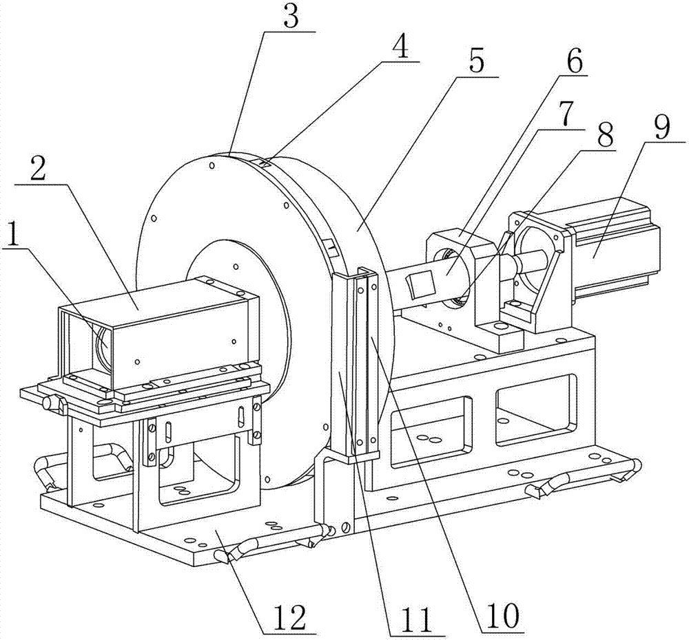
图1是X射线背散射扫描仪准直系统的立体结构示意图; Fig. 1 is the schematic diagram of the three-dimensional structure of the collimation system of the X-ray backscatter scanner;
图2是本发明的内准直器的主视结构示意图; Fig. 2 is the front view structure schematic diagram of inner collimator of the present invention;
图3是图2的左视结构示意图; Fig. 3 is a schematic diagram of the left view structure of Fig. 2;
图4是本发明的准直器和中空环形圆盘连接剖视结构示意图; Fig. 4 is the schematic diagram of the cross-sectional structure of the connection between the collimator and the hollow annular disc of the present invention;
图5是图4的俯视结构示意图; Fig. 5 is a top view structural schematic diagram of Fig. 4;
图6是本发明的外准直器和外准直器支架的连接结构示意图; Fig. 6 is a schematic diagram of the connection structure of the external collimator and the external collimator support of the present invention;
图7是本发明的X射线背散射扫描仪准直系统的原理示意图。 Fig. 7 is a schematic diagram of the principle of the collimation system of the X-ray backscatter scanner of the present invention.
图中,标号1为射线源,标号2为射线源屏蔽罩,标号3为中空环形转盘,标号4为中准直器,标号5为驱动转盘,标号6为转轴支撑架,标号7为转轴,标号8为圆锥滚子轴承,标号9为驱动电机,标号10为外准直块,标号11为外准直器支架,标号12为机架,标号13为内准直器槽,标号14为内准直器,标号15为外准直器上的透光槽,标号16为中空圆环转盘上的通光槽,标号17为被测物品,标号18为外准直器。
In the figure, the
具体实施方式 Detailed ways
下面结合附图及具体实施方式对本发明的X射线背散射扫描仪准直系统做更加详细的描述。 The collimation system of the X-ray backscatter scanner of the present invention will be described in more detail below in conjunction with the accompanying drawings and specific embodiments.
参见图1-7,一种X射线背散射扫描仪准直系统,包括内准直器14、中准直器4和外准直器18三级准直器,所述三级准直器都是重金属材料(铅,或钨,或铜,或锌,或银及其合金)制成,内准直器14为矩形板,内准直器固定在X射线扫描仪的射线源1出口,内准直器14在正对射线源一侧的重金属材料上开有一条纵向的矩形内准直器槽13;在X射线背散射扫描仪的机架12上射线源的一侧垂直安装有一个可以旋转的中空环形圆盘3,中空环形圆盘上均布有通光槽16,中准直器4固定在通光槽16上,中准直器4为矩形体,在中准直器4上开有一个楔形的中准直槽,中准直槽开口较大的一端朝向射线源方向,射线源1的焦点位于中准直槽中心轴线上;在机架12上对应中空环形圆盘3的侧面固定安装有铜质的外准直器支架11,外准直器支架11中间开有竖直的透光槽15,透光槽左、右两侧其中一侧固定或滑动连接一块外准直块10,另一侧滑动连接另一块外准直块10,两块梯形外准直块相对放置中间形成有一条楔形孔,楔形孔的中心线和中准直槽的中心线在同一条直线上,外准直块10和外准直器18支架通过一个椭圆形凹槽和螺栓滑动连接固定,外准直块10的横截面为梯形;射线源照射出来的扇形光束经内、中、外三级准直系统最后形成一条矩形投射带。
Referring to Figures 1-7, a collimation system for an X-ray backscatter scanner includes an
中空环形圆盘由驱动电机9驱动旋转,驱动电机9的转轴7上连接有一个驱动转盘5,中空环形圆盘3和驱动转盘5固定连接,在转轴中间部分设有转轴支撑架6,转轴支撑架与转轴之间设有两个相对放置的圆锥滚子轴承8,转轴与轴承之间为无缝连接。
The hollow annular disc is driven to rotate by the driving
射线源1开启后,产生锥束射线,经内准直器14准直为竖直方向上的扇形射线,扇形射线投射在中空环形转盘3内侧。驱动电机9带动中空环形转盘3开始旋转,扇形射线通过中空圆环转盘上的通光槽16及中准直器4后,准直成为窄扇束射线,再经过外准直器18的准直,最终形成在竖直方向运动的飞点光斑,投射到被测物体17上。
After the
Claims (7)
Priority Applications (1)
| Application Number | Priority Date | Filing Date | Title |
|---|---|---|---|
| CN2012101662700A CN102680501B (en) | 2012-05-26 | 2012-05-26 | Collimation system for X-ray backscatter scanner |
Applications Claiming Priority (1)
| Application Number | Priority Date | Filing Date | Title |
|---|---|---|---|
| CN2012101662700A CN102680501B (en) | 2012-05-26 | 2012-05-26 | Collimation system for X-ray backscatter scanner |
Publications (2)
| Publication Number | Publication Date |
|---|---|
| CN102680501A CN102680501A (en) | 2012-09-19 |
| CN102680501B true CN102680501B (en) | 2013-11-20 |
Family
ID=46812759
Family Applications (1)
| Application Number | Title | Priority Date | Filing Date |
|---|---|---|---|
| CN2012101662700A Active CN102680501B (en) | 2012-05-26 | 2012-05-26 | Collimation system for X-ray backscatter scanner |
Country Status (1)
| Country | Link |
|---|---|
| CN (1) | CN102680501B (en) |
Families Citing this family (9)
| Publication number | Priority date | Publication date | Assignee | Title |
|---|---|---|---|---|
| CN103901064B (en) * | 2012-12-27 | 2017-05-10 | 清华大学 | Ray emission device, imaging system and inspection method |
| CN103808744A (en) * | 2014-03-12 | 2014-05-21 | 北京曼德克环境科技有限公司 | Green channel vehicle detector for inversely scattering X-ray |
| CN103997839B (en) * | 2014-06-06 | 2018-03-30 | 同方威视技术股份有限公司 | It is a kind of to collimate modulated X-ray emitter |
| CN107315022A (en) * | 2017-07-21 | 2017-11-03 | 中国地质大学(武汉) | A kind of X-ray collimation location adjusting device and system |
| DE102017214196A1 (en) * | 2017-08-15 | 2019-02-21 | Siemens Healthcare Gmbh | X-ray system and method for its operation |
| CN107314213A (en) * | 2017-08-30 | 2017-11-03 | 中国电子科技集团公司第二十九研究所 | A kind of hollow eccentric turntable |
| CN110243848B (en) * | 2019-06-20 | 2022-04-01 | 中国科学院上海高等研究院 | X-ray beam light barrier and using method thereof |
| CN115609018A (en) * | 2022-11-02 | 2023-01-17 | 广州润合光电科技有限公司 | Metal 3D printing device with simultaneous quality inspection |
| CN119618117B (en) * | 2024-12-11 | 2025-09-26 | 合肥工业大学 | X-ray measurement facula collimation system |
Citations (5)
| Publication number | Priority date | Publication date | Assignee | Title |
|---|---|---|---|---|
| US4228357A (en) * | 1978-12-04 | 1980-10-14 | American Science And Engineering, Inc. | Detector on wheel system (flying spot) |
| CN2645079Y (en) * | 2003-08-22 | 2004-09-29 | 貊大卫 | Backscattering X-ray scanner |
| CN2872353Y (en) * | 2006-01-10 | 2007-02-21 | 上海英迈吉东影图像设备有限公司 | Safety determiner by back scattering technology |
| CN2927043Y (en) * | 2006-07-25 | 2007-07-25 | 上海英迈吉东影图像设备有限公司 | Apparatus for inspecting explosive by back scattering technology |
| CN101113961A (en) * | 2006-07-27 | 2008-01-30 | 上海英迈吉东影图像设备有限公司 | Image-forming system with X-ray backscattering and tomography scanning |
-
2012
- 2012-05-26 CN CN2012101662700A patent/CN102680501B/en active Active
Patent Citations (5)
| Publication number | Priority date | Publication date | Assignee | Title |
|---|---|---|---|---|
| US4228357A (en) * | 1978-12-04 | 1980-10-14 | American Science And Engineering, Inc. | Detector on wheel system (flying spot) |
| CN2645079Y (en) * | 2003-08-22 | 2004-09-29 | 貊大卫 | Backscattering X-ray scanner |
| CN2872353Y (en) * | 2006-01-10 | 2007-02-21 | 上海英迈吉东影图像设备有限公司 | Safety determiner by back scattering technology |
| CN2927043Y (en) * | 2006-07-25 | 2007-07-25 | 上海英迈吉东影图像设备有限公司 | Apparatus for inspecting explosive by back scattering technology |
| CN101113961A (en) * | 2006-07-27 | 2008-01-30 | 上海英迈吉东影图像设备有限公司 | Image-forming system with X-ray backscattering and tomography scanning |
Also Published As
| Publication number | Publication date |
|---|---|
| CN102680501A (en) | 2012-09-19 |
Similar Documents
| Publication | Publication Date | Title |
|---|---|---|
| CN102680501B (en) | Collimation system for X-ray backscatter scanner | |
| JP4558372B2 (en) | Collimator assembly with multiple components | |
| CN102768219B (en) | Combined nondestructive testing method and combined nondestructive testing system | |
| JP5559875B2 (en) | Multi-detector array imaging system | |
| CN106996939B (en) | Tomography inspection device | |
| JP6125704B2 (en) | Collimator | |
| US9042514B2 (en) | Dose reduction via dynamic collimation adjustment for targeted field of view and/or digital tilt CT | |
| WO2008031313A1 (en) | Multiple dr/ct detection device of containers | |
| CN104749197A (en) | Ct system and method thereof | |
| CA2902952A1 (en) | Vehicle-mounted inspection system | |
| CN104764759B (en) | A kind of wire jumper flying spot scanning device for X ray back scattering imaging system | |
| CN105891898A (en) | Ray irradiation device and safety detection equipment | |
| CN104853679A (en) | Radiation beam intensity profile shaper | |
| CN1965759A (en) | Radiological imaging apparatus and transmission imaging method | |
| CN105445288A (en) | Novel combined movable inspection system | |
| JP6538721B2 (en) | Method of two-color radiography using laser and Compton X-ray source | |
| KR101209516B1 (en) | X-ray analysis apparatus having shutter device | |
| CN102901741A (en) | X-ray flying-spot scanning generator | |
| CN202599874U (en) | X-ray backscattering scanner mechanical device | |
| US9757088B2 (en) | Detector apparatus for cone beam computed tomography | |
| CN105158282B (en) | A kind of scanning means for back scattering imaging system | |
| CN200956017Y (en) | Container multiple DR/CT detecting device | |
| JP5680510B2 (en) | Charged particle beam irradiation equipment | |
| US12125605B2 (en) | Rotating hoop chopper wheel for x-ray imagers | |
| KR101610142B1 (en) | Apparatus and method for computed tomography |
Legal Events
| Date | Code | Title | Description |
|---|---|---|---|
| C06 | Publication | ||
| PB01 | Publication | ||
| C10 | Entry into substantive examination | ||
| SE01 | Entry into force of request for substantive examination | ||
| C14 | Grant of patent or utility model | ||
| GR01 | Patent grant |