CN101932780B - Mechanical locking of floor panels, methods of installing and removing panels, method and apparatus for producing locking systems, method of connecting displaceable tongues with panels and tongue grooves - Google Patents
Mechanical locking of floor panels, methods of installing and removing panels, method and apparatus for producing locking systems, method of connecting displaceable tongues with panels and tongue grooves Download PDFInfo
- Publication number
- CN101932780B CN101932780B CN2009801034591A CN200980103459A CN101932780B CN 101932780 B CN101932780 B CN 101932780B CN 2009801034591 A CN2009801034591 A CN 2009801034591A CN 200980103459 A CN200980103459 A CN 200980103459A CN 101932780 B CN101932780 B CN 101932780B
- Authority
- CN
- China
- Prior art keywords
- tongue
- edge
- groove
- locking
- edges
- Prior art date
- Legal status (The legal status is an assumption and is not a legal conclusion. Google has not performed a legal analysis and makes no representation as to the accuracy of the status listed.)
- Active
Links
Images


Classifications
-
- E—FIXED CONSTRUCTIONS
- E04—BUILDING
- E04F—FINISHING WORK ON BUILDINGS, e.g. STAIRS, FLOORS
- E04F15/00—Flooring
- E04F15/02—Flooring or floor layers composed of a number of similar elements
- E04F15/02038—Flooring or floor layers composed of a number of similar elements characterised by tongue and groove connections between neighbouring flooring elements
-
- B—PERFORMING OPERATIONS; TRANSPORTING
- B27—WORKING OR PRESERVING WOOD OR SIMILAR MATERIAL; NAILING OR STAPLING MACHINES IN GENERAL
- B27F—DOVETAILED WORK; TENONS; SLOTTING MACHINES FOR WOOD OR SIMILAR MATERIAL; NAILING OR STAPLING MACHINES
- B27F1/00—Dovetailed work; Tenons; Making tongues or grooves; Groove- and- tongue jointed work; Finger- joints
- B27F1/08—Making dovetails, tongues, or tenons, of definite limited length
-
- B—PERFORMING OPERATIONS; TRANSPORTING
- B27—WORKING OR PRESERVING WOOD OR SIMILAR MATERIAL; NAILING OR STAPLING MACHINES IN GENERAL
- B27G—ACCESSORY MACHINES OR APPARATUS FOR WORKING WOOD OR SIMILAR MATERIALS; TOOLS FOR WORKING WOOD OR SIMILAR MATERIALS; SAFETY DEVICES FOR WOOD WORKING MACHINES OR TOOLS
- B27G13/00—Cutter blocks; Other rotary cutting tools
- B27G13/12—Cutter blocks; Other rotary cutting tools for profile cutting
- B27G13/14—Cutter blocks; Other rotary cutting tools for profile cutting for cutting grooves or tenons
-
- B—PERFORMING OPERATIONS; TRANSPORTING
- B27—WORKING OR PRESERVING WOOD OR SIMILAR MATERIAL; NAILING OR STAPLING MACHINES IN GENERAL
- B27M—WORKING OF WOOD NOT PROVIDED FOR IN SUBCLASSES B27B - B27L; MANUFACTURE OF SPECIFIC WOODEN ARTICLES
- B27M3/00—Manufacture or reconditioning of specific semi-finished or finished articles
- B27M3/0013—Manufacture or reconditioning of specific semi-finished or finished articles of composite or compound articles
- B27M3/0066—Manufacture or reconditioning of specific semi-finished or finished articles of composite or compound articles characterised by tongue and groove or tap hole connections
-
- E—FIXED CONSTRUCTIONS
- E04—BUILDING
- E04B—GENERAL BUILDING CONSTRUCTIONS; WALLS, e.g. PARTITIONS; ROOFS; FLOORS; CEILINGS; INSULATION OR OTHER PROTECTION OF BUILDINGS
- E04B5/00—Floors; Floor construction with regard to insulation; Connections specially adapted therefor
- E04B5/02—Load-carrying floor structures formed substantially of prefabricated units
- E04B5/023—Separate connecting devices for prefabricated floor-slabs
-
- E—FIXED CONSTRUCTIONS
- E04—BUILDING
- E04F—FINISHING WORK ON BUILDINGS, e.g. STAIRS, FLOORS
- E04F15/00—Flooring
- E04F15/02—Flooring or floor layers composed of a number of similar elements
-
- E—FIXED CONSTRUCTIONS
- E04—BUILDING
- E04F—FINISHING WORK ON BUILDINGS, e.g. STAIRS, FLOORS
- E04F15/00—Flooring
- E04F15/02—Flooring or floor layers composed of a number of similar elements
- E04F15/02005—Construction of joints, e.g. dividing strips
-
- E—FIXED CONSTRUCTIONS
- E04—BUILDING
- E04F—FINISHING WORK ON BUILDINGS, e.g. STAIRS, FLOORS
- E04F13/00—Coverings or linings, e.g. for walls or ceilings
- E04F13/07—Coverings or linings, e.g. for walls or ceilings composed of covering or lining elements; Sub-structures therefor; Fastening means therefor
- E04F13/08—Coverings or linings, e.g. for walls or ceilings composed of covering or lining elements; Sub-structures therefor; Fastening means therefor composed of a plurality of similar covering or lining elements
- E04F13/0889—Coverings or linings, e.g. for walls or ceilings composed of covering or lining elements; Sub-structures therefor; Fastening means therefor composed of a plurality of similar covering or lining elements characterised by the joints between neighbouring elements, e.g. with joint fillings or with tongue and groove connections
- E04F13/0892—Coverings or linings, e.g. for walls or ceilings composed of covering or lining elements; Sub-structures therefor; Fastening means therefor composed of a plurality of similar covering or lining elements characterised by the joints between neighbouring elements, e.g. with joint fillings or with tongue and groove connections with means for aligning the outer surfaces of the covering elements
-
- E—FIXED CONSTRUCTIONS
- E04—BUILDING
- E04F—FINISHING WORK ON BUILDINGS, e.g. STAIRS, FLOORS
- E04F15/00—Flooring
- E04F15/02—Flooring or floor layers composed of a number of similar elements
- E04F15/04—Flooring or floor layers composed of a number of similar elements only of wood or with a top layer of wood, e.g. with wooden or metal connecting members
-
- E—FIXED CONSTRUCTIONS
- E04—BUILDING
- E04F—FINISHING WORK ON BUILDINGS, e.g. STAIRS, FLOORS
- E04F21/00—Implements for finishing work on buildings
- E04F21/0092—Separate provisional spacers used between adjacent floor or wall tiles
-
- E—FIXED CONSTRUCTIONS
- E04—BUILDING
- E04F—FINISHING WORK ON BUILDINGS, e.g. STAIRS, FLOORS
- E04F21/00—Implements for finishing work on buildings
- E04F21/18—Implements for finishing work on buildings for setting wall or ceiling slabs or plates
- E04F21/1838—Implements for finishing work on buildings for setting wall or ceiling slabs or plates for setting a plurality of similar elements
- E04F21/1844—Implements for finishing work on buildings for setting wall or ceiling slabs or plates for setting a plurality of similar elements by applying them one by one
-
- E—FIXED CONSTRUCTIONS
- E04—BUILDING
- E04F—FINISHING WORK ON BUILDINGS, e.g. STAIRS, FLOORS
- E04F21/00—Implements for finishing work on buildings
- E04F21/20—Implements for finishing work on buildings for laying flooring
- E04F21/22—Implements for finishing work on buildings for laying flooring of single elements, e.g. flooring cramps ; flexible webs
-
- E—FIXED CONSTRUCTIONS
- E04—BUILDING
- E04F—FINISHING WORK ON BUILDINGS, e.g. STAIRS, FLOORS
- E04F2201/00—Joining sheets or plates or panels
- E04F2201/01—Joining sheets, plates or panels with edges in abutting relationship
- E04F2201/0107—Joining sheets, plates or panels with edges in abutting relationship by moving the sheets, plates or panels substantially in their own plane, perpendicular to the abutting edges
-
- E—FIXED CONSTRUCTIONS
- E04—BUILDING
- E04F—FINISHING WORK ON BUILDINGS, e.g. STAIRS, FLOORS
- E04F2201/00—Joining sheets or plates or panels
- E04F2201/01—Joining sheets, plates or panels with edges in abutting relationship
- E04F2201/0123—Joining sheets, plates or panels with edges in abutting relationship by moving the sheets, plates or panels parallel to the abutting edges
-
- E—FIXED CONSTRUCTIONS
- E04—BUILDING
- E04F—FINISHING WORK ON BUILDINGS, e.g. STAIRS, FLOORS
- E04F2201/00—Joining sheets or plates or panels
- E04F2201/01—Joining sheets, plates or panels with edges in abutting relationship
- E04F2201/0138—Joining sheets, plates or panels with edges in abutting relationship by moving the sheets, plates or panels perpendicular to the main plane
-
- E—FIXED CONSTRUCTIONS
- E04—BUILDING
- E04F—FINISHING WORK ON BUILDINGS, e.g. STAIRS, FLOORS
- E04F2201/00—Joining sheets or plates or panels
- E04F2201/01—Joining sheets, plates or panels with edges in abutting relationship
- E04F2201/0153—Joining sheets, plates or panels with edges in abutting relationship by rotating the sheets, plates or panels around an axis which is parallel to the abutting edges, possibly combined with a sliding movement
- E04F2201/0161—Joining sheets, plates or panels with edges in abutting relationship by rotating the sheets, plates or panels around an axis which is parallel to the abutting edges, possibly combined with a sliding movement with snap action of the edge connectors
-
- E—FIXED CONSTRUCTIONS
- E04—BUILDING
- E04F—FINISHING WORK ON BUILDINGS, e.g. STAIRS, FLOORS
- E04F2201/00—Joining sheets or plates or panels
- E04F2201/02—Non-undercut connections, e.g. tongue and groove connections
- E04F2201/021—Non-undercut connections, e.g. tongue and groove connections with separate protrusions
- E04F2201/022—Non-undercut connections, e.g. tongue and groove connections with separate protrusions with tongue or grooves alternating longitudinally along the edge
-
- E—FIXED CONSTRUCTIONS
- E04—BUILDING
- E04F—FINISHING WORK ON BUILDINGS, e.g. STAIRS, FLOORS
- E04F2201/00—Joining sheets or plates or panels
- E04F2201/02—Non-undercut connections, e.g. tongue and groove connections
- E04F2201/025—Non-undercut connections, e.g. tongue and groove connections with tongue and grooves alternating transversally in the direction of the thickness of the panel, e.g. multiple tongue and grooves oriented parallel to each other
-
- E—FIXED CONSTRUCTIONS
- E04—BUILDING
- E04F—FINISHING WORK ON BUILDINGS, e.g. STAIRS, FLOORS
- E04F2201/00—Joining sheets or plates or panels
- E04F2201/04—Other details of tongues or grooves
- E04F2201/041—Tongues or grooves with slits or cuts for expansion or flexibility
-
- E—FIXED CONSTRUCTIONS
- E04—BUILDING
- E04F—FINISHING WORK ON BUILDINGS, e.g. STAIRS, FLOORS
- E04F2201/00—Joining sheets or plates or panels
- E04F2201/05—Separate connectors or inserts, e.g. pegs, pins, keys or strips
- E04F2201/0523—Separate tongues; Interlocking keys, e.g. joining mouldings of circular, square or rectangular shape
- E04F2201/0529—Separate tongues; Interlocking keys, e.g. joining mouldings of circular, square or rectangular shape the interlocking key acting as a dovetail-type key
-
- E—FIXED CONSTRUCTIONS
- E04—BUILDING
- E04F—FINISHING WORK ON BUILDINGS, e.g. STAIRS, FLOORS
- E04F2201/00—Joining sheets or plates or panels
- E04F2201/05—Separate connectors or inserts, e.g. pegs, pins, keys or strips
- E04F2201/0523—Separate tongues; Interlocking keys, e.g. joining mouldings of circular, square or rectangular shape
- E04F2201/0535—Separate tongues; Interlocking keys, e.g. joining mouldings of circular, square or rectangular shape adapted for snap locking
-
- E—FIXED CONSTRUCTIONS
- E04—BUILDING
- E04F—FINISHING WORK ON BUILDINGS, e.g. STAIRS, FLOORS
- E04F2201/00—Joining sheets or plates or panels
- E04F2201/05—Separate connectors or inserts, e.g. pegs, pins, keys or strips
- E04F2201/0523—Separate tongues; Interlocking keys, e.g. joining mouldings of circular, square or rectangular shape
- E04F2201/0541—Separate tongues; Interlocking keys, e.g. joining mouldings of circular, square or rectangular shape adapted to be moved along the joint edge
-
- E—FIXED CONSTRUCTIONS
- E04—BUILDING
- E04F—FINISHING WORK ON BUILDINGS, e.g. STAIRS, FLOORS
- E04F2201/00—Joining sheets or plates or panels
- E04F2201/05—Separate connectors or inserts, e.g. pegs, pins, keys or strips
- E04F2201/0523—Separate tongues; Interlocking keys, e.g. joining mouldings of circular, square or rectangular shape
- E04F2201/0552—Separate tongues; Interlocking keys, e.g. joining mouldings of circular, square or rectangular shape adapted to be rotated around an axis parallel to the joint edge
-
- Y—GENERAL TAGGING OF NEW TECHNOLOGICAL DEVELOPMENTS; GENERAL TAGGING OF CROSS-SECTIONAL TECHNOLOGIES SPANNING OVER SEVERAL SECTIONS OF THE IPC; TECHNICAL SUBJECTS COVERED BY FORMER USPC CROSS-REFERENCE ART COLLECTIONS [XRACs] AND DIGESTS
- Y10—TECHNICAL SUBJECTS COVERED BY FORMER USPC
- Y10T—TECHNICAL SUBJECTS COVERED BY FORMER US CLASSIFICATION
- Y10T29/00—Metal working
- Y10T29/49—Method of mechanical manufacture
- Y10T29/49815—Disassembling
- Y10T29/49822—Disassembling by applying force
-
- Y—GENERAL TAGGING OF NEW TECHNOLOGICAL DEVELOPMENTS; GENERAL TAGGING OF CROSS-SECTIONAL TECHNOLOGIES SPANNING OVER SEVERAL SECTIONS OF THE IPC; TECHNICAL SUBJECTS COVERED BY FORMER USPC CROSS-REFERENCE ART COLLECTIONS [XRACs] AND DIGESTS
- Y10—TECHNICAL SUBJECTS COVERED BY FORMER USPC
- Y10T—TECHNICAL SUBJECTS COVERED BY FORMER US CLASSIFICATION
- Y10T29/00—Metal working
- Y10T29/49—Method of mechanical manufacture
- Y10T29/49826—Assembling or joining
-
- Y—GENERAL TAGGING OF NEW TECHNOLOGICAL DEVELOPMENTS; GENERAL TAGGING OF CROSS-SECTIONAL TECHNOLOGIES SPANNING OVER SEVERAL SECTIONS OF THE IPC; TECHNICAL SUBJECTS COVERED BY FORMER USPC CROSS-REFERENCE ART COLLECTIONS [XRACs] AND DIGESTS
- Y10—TECHNICAL SUBJECTS COVERED BY FORMER USPC
- Y10T—TECHNICAL SUBJECTS COVERED BY FORMER US CLASSIFICATION
- Y10T83/00—Cutting
- Y10T83/04—Processes
Landscapes
- Engineering & Computer Science (AREA)
- Architecture (AREA)
- Life Sciences & Earth Sciences (AREA)
- Wood Science & Technology (AREA)
- Civil Engineering (AREA)
- Structural Engineering (AREA)
- Forests & Forestry (AREA)
- Mechanical Engineering (AREA)
- Manufacturing & Machinery (AREA)
- Physics & Mathematics (AREA)
- Electromagnetism (AREA)
- Floor Finish (AREA)
- Joining Of Building Structures In Genera (AREA)
Abstract
Description
技术领域 technical field
本发明一般涉及具有机械锁定系统的地板镶板领域,所述机械锁定系统包括允许容易地安装的独立的可位移榫舌。本发明提供了安装和拆卸建筑镶板特别是地板镶板的新的改进的锁定系统和方法以及生产该锁定系统的方法。The present invention generally relates to the field of floor panels with a mechanical locking system comprising independently displaceable tongues allowing easy installation. The present invention provides a new and improved locking system and method for installing and removing building panels, in particular floor panels, and a method of producing the locking system.
背景技术 Background technique
特别地但非限制性地,本发明涉及一种用于具有长边缘和短边缘的矩形地板镶板的机械锁定系统。这种地板镶板一般利用长边缘的偏角调节(angling)来安装。短边缘可以利用沿着短边缘的偏角调节、水平卡锁或插入而连接。安装需要三个动作,因为还需要在锁定位置的位移来锁定所有四个边。In particular but not limitatively, the present invention relates to a mechanical locking system for rectangular floor panels having long and short edges. Such floor panels are generally installed with angling of the long edges. The short edges can be connected with angling, horizontal snapping or insertion along the short edges. Three actions are required for installation, as displacement in the locked position is also required to lock all four sides.
还从US 2003/0101681A1中已知,锁定系统可以形成在具有榫舌和凹槽包括凸起和凹进的短边缘上,使得短边缘可以水平地移动而接触,并随后沿短边缘移动和锁定。长边缘随后利用偏角调节锁定。这种锁定系统和安装方法是基于与已知的短边缘插入相同的原理。仅有的优点是短边缘的位移可以从约0.1-0.2m(传统地板镶板的宽度)减少至数厘米,并且这个小优点一般会由于利用地板生产中使用的机加工类型形成凸起和凹进而附加的成本而被消除。It is also known from US 2003/0101681 A1 that a locking system can be formed on the short edge with a tongue and groove including protrusions and recesses, so that the short edge can be moved horizontally into contact and subsequently moved along the short edge and locked . The long edges are then locked using the angling adjustment. This locking system and installation method is based on the same principle as the known short edge insertion. The only advantage is that the displacement of the short edge can be reduced from about 0.1-0.2m (the width of a traditional floor panel) to a few centimeters, and this small advantage is generally due to the formation of the protrusions and recesses with the type of machining used in floor production. The additional costs are thus eliminated.
应强调的是,长边缘和短边缘仅用于简化描述。镶板还可以是方形的,其可以具有多于4个边缘且相邻边缘可以具有非90度角。然而,本发明一般也适用于建筑镶板。更特别地,本发明主要涉及这种类型的机械锁定系统,该系统允许长边缘的偏角调节,短边缘的竖直移动可以利用一般被称为竖直叠合的单一动作方法将镶板的所有四个边缘与其它镶板锁定。然而,本发明的主要原理还可以用于上文和下文描述的其它类型的已知机械锁定系统中。It should be emphasized that the long and short edges are only used to simplify the description. Panels can also be square, which can have more than 4 edges and adjacent edges can have non-90 degree angles. However, the invention is also applicable to building panels in general. More particularly, the present invention relates primarily to mechanical locking systems of the type that allow angling of the long edges and vertical movement of the short edges to align the panel's All four edges lock to other panels. However, the main principles of the invention can also be used in other types of known mechanical locking systems described above and below.
这种类型的地板镶板(图1a)在WO2006/043893(申请人
在长边缘的偏角调节期间,当柔性榫舌或榫舌的柔性部分在双重动作中水平地位移时,这种类型的竖直锁定和竖直叠合在短边缘上产生分离压力。榫舌的一部分在锁定的起始部分期间向内位移,并随后在锁定动作的最终部分期间朝向起始位置位移。发明人已经分析了几种类型的地板镶板并发现存在相当大的风险,即,短边缘会在安装过程中被互相推开,并且在短边缘的边缘部分之间会产生间隙。这种间隙会阻止进一步安装,地板镶板将不可能连接。还会导致在短边缘处对锁定系统的严重损坏。在安装过程中侧向地朝短边缘推动地板块可以避免间隙。然而这种安装方法很复杂且难于使用,因为三个动作必须结合并且结合长边缘的向下偏角调节同时使用。This type of vertical locking and vertical folding creates a separation pressure on the short edges when the flexible tongue or flexible part of the tongue is displaced horizontally in a double action during angling of the long edges. A part of the tongue is displaced inwardly during the initial part of locking and then towards the starting position during the final part of the locking action. The inventors have analyzed several types of floor panels and found that there is a considerable risk that the short edges will be pushed away from each other during installation and that gaps will be created between the edge portions of the short edges. Such a gap would prevent further installation and it would be impossible to connect the floor panels. It can also cause severe damage to the locking system at the short edges. Pushing the floorboards sideways towards the short edges during installation avoids gaps. However, this mounting method is complex and difficult to use, since three actions must be combined and used simultaneously in conjunction with downward angling of the long edge.
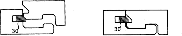
还已知的是,如图1c所示,第一行的两个相邻短边缘可以利用可位移榫舌(30)锁定,当相邻短边缘已经向下叠合并且定位在相同平面内时,通过在一个边缘部分(32)处的侧推使所述榫舌位移和例如弯曲,如图1d所示。这种安装在DE 1020060376114B3和由
图2a、2b、2c、3a和3b示出了已知的柔性榫舌30的剖面的示例,该榫舌可以用于根据已知的竖直卡锁叠合技术锁定短边缘。图2a示出了具有向下延伸的柔性卡锁凸片的单独的榫舌30。图2b示出了具有在位移凹槽内的柔性卡锁凸片的单独的榫舌。图2c示出了根据图1a和1b在锁定过程中水平地弯曲的柔性榫舌30。图3a示出了柔性榫舌的实施例,该榫舌利用转动和卡锁动作的组合而锁定。这种锁定系统可以不用任何分离力而锁定。然而在锁定过程中很难造成和产生相当大的阻力。图3b示出了柔性榫舌,该榫舌利用预紧力连接在凹槽内,并且当预紧力被释放时弹出到榫舌凹槽中。图3c示出了根据图1c和1d的柔性榫舌,该榫舌利用来自一个凹槽的侧向压力位移进入相邻榫舌凹槽。Figures 2a, 2b, 2c, 3a and 3b show examples of cross-sections of known
根据已知技术的竖直叠合要求锁定系统的某些部分——一般是单独的榫舌的某些部分——在边缘被锁定时被弯曲或压紧,如上文所示。这可以使用侧推技术利用楔形的单独榫舌避免。这种楔形榫舌一般包括两个部分或者它们与凹槽连接,这些凹槽与边缘是不平行的。这导致必须使用昂贵材料或复杂生产方法的事实。Vertical lamination according to known technology requires that certain parts of the locking system - generally certain parts of the individual tongue - be bent or compressed when the edges are locked, as indicated above. This can be avoided with wedge-shaped individual tongues using the side push technique. Such dovetail tongues generally consist of two parts or they are connected with grooves which are not parallel to the edge. This leads to the fact that expensive materials or complicated production methods have to be used.
所有这些已知实施例将在利用竖直叠合的安装过程中产生分离压力或锁定阻力。这可以导致短边缘发生分离,使得锁定系统将被破坏或使得镶板将难以安装。与利用偏角调节和水平卡锁的结合进行安装的传统的机械锁定系统相比,锁定强度、锁定质量和生产成本在某些已知的竖直锁定系统中是没有竞争力的。All of these known embodiments will create separation pressure or locking resistance during installation with vertical lapping. This can cause the short edges to separate so that the locking system will be broken or the panels will be difficult to install. Locking strength, locking quality and production costs are not competitive with some known vertical locking systems compared to conventional mechanical locking systems installed with a combination of angling and horizontal snapping.
如果可以消除分离和阻力问题,并且如果可以改进生产成本和锁定质量,那么使用竖直叠合安装方法的锁定系统可以取得显著的更大的市场份额。If separation and drag problems could be eliminated, and if production costs and locking quality could be improved, then locking systems using vertical stack installation methods could achieve significantly greater market share.
本发明的主要目的是提供能尽可能地避免锁定过程中的这种分离和阻力问题并且优选地可以使用非柔性材料或仅包括一个单独部分的榫舌的技术方案。The main purpose of the present invention is to provide a solution that avoids as much as possible such problems of separation and resistance during locking and preferably allows the use of non-flexible materials or a tongue comprising only one single part.
多个上述已知锁定原理和安装方法可以用于本发明所述的实施例,本发明的与锁定系统、安装和生产方法的特定部分相关的基本原理也可用于已知的现有技术的锁定系统。Many of the above-mentioned known locking principles and installation methods can be used for the embodiments described in the present invention, and the basic principles of the invention related to certain parts of the locking system, installation and production method can also be used for known prior art locking system.
术语的定义Definition of terms
在下文中,安装好的地板镶板的可视表面被称为“正面”,地板镶板的面对底层地板的相对侧面被称为“背面”。正面和背面之间的边缘被称为“接头边缘”。如果没有另行定义,上和下指的是朝向正面和朝向背面。内和外指的是朝向或背离镶板中心。“水平面”指的是平行于表面层的外部延伸的平面。两个接合地板镶板的两个相邻接头边缘的紧邻并置的上部共同限定了与水平面垂直的“竖直平面”。“水平”指的是与水平面平行,“竖直”指的是与竖直平面平行。In the following, the visible surface of the installed floor panel is referred to as the "front side" and the opposite side of the floor panel facing the sub-floor is referred to as the "rear side". The edge between the front and back is called the "joint edge". If not defined otherwise, upper and lower refer to towards the front and towards the back. In and out refer to toward or away from the center of the panel. By "horizontal plane" is meant a plane extending parallel to the exterior of the surface layer. The immediately juxtaposed upper portions of two adjacent joint edges of two joined floor panels together define a "vertical plane" perpendicular to the horizontal plane. "Horizontal" means parallel to a horizontal plane, and "vertical" means parallel to a vertical plane.
“接头”或“锁定系统”指的是共同作用的连接机构,其竖直和/或水平地连接地板镶板。“机械锁定系统”指的是可在不使用胶合剂的情况下实现接合。机械锁定系统在许多情况下还可通过胶合相结合。“集成”指的是与镶板形成一个整体,或者在工厂被连接到镶板。“单独”部分、部件元件和类似物指的是它们被单独地生产且与镶板的芯部或主体不是一个整体。单独部分一般在工厂与镶板连接和集成,但它们可以作为脱离件被提供,这些脱离件旨在在镶板的安装过程中使用。"Joints" or "locking systems" refer to co-acting connection mechanisms that connect floor panels vertically and/or horizontally. "Mechanical locking system" means that the joint can be achieved without the use of glue. Mechanical locking systems can in many cases also be combined by gluing. "Integrated" means formed as one piece with, or attached to, a panel at the factory. "Separate" parts, component elements and the like mean that they are produced separately and are not integral to the core or body of the panel. The separate parts are generally attached and integrated with the panels at the factory, but they may be supplied as breakaway pieces intended for use during installation of the panels.
“单独的榫舌”指的是用单独材料制成、与镶板的一个边缘连接的榫舌,该榫舌具有沿接头边缘的长度方向,并形成竖直锁定系统的一部分。"Separate tongue" means a tongue of a separate material attached to one edge of a panel, the tongue having a length along the edge of the joint and forming part of a vertical locking system.
“可位移榫舌”指的是任意类型的、将相邻边缘竖直连接的榫舌,该榫舌用单独材料制成和与地板镶板连接,并且该榫舌可在解锁位置与锁定位置之间完全地或部分地位移。可位移榫舌可以是柔性的或刚性的。"Displaceable tongue" means any type of tongue connecting adjacent edges vertically, which is made of a separate material and which is connected to the floor panel and which can be moved between the unlocked and locked positions fully or partially displaced. The displaceable tongue can be flexible or rigid.
“榫舌”一般指的是在边缘部分中的一部分,该部分延伸超过上边缘且与相邻边缘中的凹槽协作,使得边缘被竖直锁定。榫舌一般与镶板制成一个整体。"Tongue" generally refers to a portion in an edge portion that extends beyond the upper edge and cooperates with a groove in an adjacent edge such that the edge is locked vertically. The tongue is generally made in one piece with the panel.
“偏角调节”指的是利用转动实现的连接,在此期间在正被连接或分开的两个部分之间发生角度变化。当偏角调节涉及两个地板镶板的连接时发生角向运动,在该运动的至少部分期间,接头边缘的上部至少部分地相互接触。"Angling" refers to a connection by means of rotation, during which an angular change occurs between two parts being connected or separated. When angling involves the connection of two floor panels an angular movement occurs, during at least part of this movement the upper parts of the joint edges are at least partially in contact with each other.
“偏角调节锁定系统”指的是可利用偏角调节竖直地和水平地连接的机械锁定系统,该系统包括在竖直方向上锁定两个相邻边缘的榫舌和凹槽,并包括锁定条,该锁定条具有在被称为“条板”的镶板的一个边缘中的锁定元件,该锁定元件与被称为“槽板”的镶板的另一边缘上的锁定凹槽协作,并在水平方向上锁定边缘。锁定元件和锁定凹槽具有将锁定元件引导至锁定凹槽中的大致圆化的引导表面,且具有锁定并防止边缘之间的水平分离的锁定表面。"Angling locking system" means a mechanical locking system that can be connected vertically and horizontally by angling, the system comprising a tongue and groove that locks two adjacent edges in a vertical direction, and comprising Locking strips having a locking element in one edge of a panel known as a "slat" that cooperates with a locking groove on the other edge of a panel known as a "slat" , and locks the edges horizontally. The locking element and the locking groove have substantially rounded guide surfaces that guide the locking element into the locking groove, and have locking surfaces that lock and prevent horizontal separation between the edges.
“竖直锁定”指的是在两个边缘基本竖直地靠着彼此位移时发生的锁定。"Vertical locking" refers to locking that occurs when two edges are displaced substantially vertically against each other.
“竖直叠合”指的是利用长边缘的偏角调节实现的镶板的安装,其中该长边缘偏角调节还用于水平地和/或竖直地连接短边缘。“竖直卡锁叠合”指的是在长边缘偏角调节的最终阶段利用柔性榫舌的卡锁而竖直地锁定短边缘的安装。这种锁定系统不是例如长边缘上的偏角调节锁定系统和短边缘上的竖直锁定系统的纯粹的组合,因为竖直和偏角调节动作相组合且短边缘以与剪刀相同的方式叠合在一起。从邻近被偏角调节的一个长边缘的一个边缘部分向邻近另一相对长边缘的另一边缘部分逐步地实现锁定。“竖直推动叠合”指的是在偏角调节之后当两个镶板平放在底层地板上时将这两个镶板的短边缘锁定的安装。竖直锁定利用侧推实现,该侧推使单独的榫舌在短边缘的长度方向上发生位移。在传统的向下叠合的系统中,水平锁定以与偏角调节系统相同的方法实现,该偏角调节系统在条板的一个边缘上具有锁定元件,该锁定元件与槽板的另一边缘上的锁定凹槽协作。"Vertical lamination" refers to the installation of panels with angling of the long edges, wherein the angling of the long edges is also used to connect the short edges horizontally and/or vertically. "Vertical snap-fit" refers to installations where the short edges are locked vertically by snap-locking of the flexible tongue at the final stage of angling of the long edges. This locking system is not, for example, a pure combination of an angled locking system on the long edge and a vertical locking system on the short edge, since the vertical and angled actions are combined and the short edges fold in the same way as scissors together. Locking is achieved stepwise from one edge portion adjacent to the one long edge being angled to the other edge portion adjacent the other opposite long edge. "Vertical push-to-stack" refers to an installation that locks the short edges of two panels when they lie flat on the sub-floor after angling. The vertical locking is achieved with a side push which displaces the individual tongue in the length direction of the short edge. In a traditional fold-down system, horizontal locking is achieved in the same way as a angling system, which has a locking element on one edge of the slat that engages with the other edge of the channel Cooperate with the locking groove on the.
发明内容 Contents of the invention
本发明涉及建筑镶板的套件,特别是短边缘上具有机械锁定系统的地板镶板或浮动地板,该机械锁定系统构造成用于改进利用竖直叠合进行安装的地板镶板的安装,并将在安装过程中反抗或阻止短边缘的分离。本发明的目的还在于改进这种和类似锁定系统的安装、强度、质量和生产成本。特别的目的是提供能用于锁定例如具有5-10mm厚度的薄地板块的锁定系统。The invention relates to a set of building panels, in particular floor panels or floating floors, with a mechanical locking system on the short edges configured for improved installation of floor panels installed with vertical lamination, and Will resist or prevent separation of short edges during installation. It is also an object of the invention to improve the installation, strength, quality and production costs of this and similar locking systems. A particular object is to provide a locking system that can be used for locking thin floorboards, eg having a thickness of 5-10 mm.
本发明主要涉及具有锁定系统的地板镶板,该锁定系统包括位于相邻边缘上的榫舌和榫舌凹槽。该榫舌和榫舌凹槽包括凸起和凹进,该凸起和凹进构造成使得相邻边缘可竖直地连接至其中凸起与凹进相配合的竖直解锁位置。榫舌和榫舌凹槽可以相对于彼此和沿相邻边缘位移,使得一些凸起互相重叠,从而使相邻边缘竖直地锁定。The invention mainly relates to floor panels with a locking system comprising a tongue and a tongue groove on adjacent edges. The tongue and tongue groove comprise protrusions and recesses configured such that adjacent edges can be connected vertically to a vertical unlocking position in which the protrusions cooperate with the recesses. The tongue and tongue groove can be displaced relative to each other and along the adjacent edges so that some of the projections overlap each other so that the adjacent edges are locked vertically.
这种锁定系统基本消除了竖直锁定过程中的所有竖直卡锁阻力和相邻边缘之间的所有分离力。为了竖直地移动和锁定相邻边缘而需要的唯一压力是当镶板平放在底层地板上且其相邻的顶边相接触时仅沿边缘在一个方向上的力。所有已知的可能利用竖直运动竖直地锁定的锁定系统都在竖直移动过程中产生卡锁阻力或在榫舌沿接头和垂直于接头被从一个边缘压入相邻边缘时产生与边缘垂直的分离压力。This locking system substantially eliminates all vertical snapping resistance and all separation forces between adjacent edges during vertical locking. The only pressure required to move and lock adjacent edges vertically is the force in one direction along the edges only when the panels lie flat on the subfloor with their adjacent top edges touching. All known locking systems that can be locked vertically with a vertical movement create a snapping resistance during the vertical movement or a conflict with the edge when the tongue is pressed from one edge into the adjacent edge along the joint and perpendicular to the joint. vertical separation pressure.
本发明提供了锁定系统的新实施例,该锁定系统优选位于短边缘上,但根据不同方面也位于长边缘上,提供相应的优点。本发明的可用区域是任意形状和材料、例如层压材料的墙面镶板、天花板、外部应用和地板镶板;特别是具有包含热固树脂、木材、HDF、饰面或石材的表面材料的镶板。The invention provides a new embodiment of the locking system, preferably on the short edges, but according to different aspects also on the long edges, offering corresponding advantages. Usable areas of the invention are wall panels, ceilings, exterior applications and floor panels of any shape and material such as laminate; especially with surface materials comprising thermosetting resins, wood, HDF, veneer or stone panel.
本发明根据第一方面包括具有锁定系统的地板镶板的套件,该锁定系统包括位于第一地板镶板的边缘上的榫舌和位于相似的第二地板镶板的相邻边缘上的榫舌凹槽,以用于将边缘竖直地连接。榫舌和榫舌凹槽相对于彼此可位移。榫舌包括水平地延伸到边缘的上部之外的凸起,榫舌凹槽包括凸起和凹进,该凸起和凹进构造成得使相邻边缘能够获得其中榫舌的凸起与榫舌凹槽的凹进相配合的竖直解锁位置和其中所述榫舌的凸起与所述榫舌凹槽的凸起竖直地重叠的竖直锁定位置。The invention according to a first aspect comprises a kit of floor panels with a locking system comprising a tongue on an edge of a first floor panel and a tongue on an adjacent edge of a second similar floor panel Grooves for connecting edges vertically. The tongue and the tongue groove are displaceable relative to each other. The tongue comprises a protrusion extending horizontally beyond the upper part of the edge, and the tongue groove comprises a protrusion and a recess configured such that an adjacent edge can obtain the protrusion and tenon of the tongue therein. A vertical unlocked position in which the recesses of the tongue-groove cooperate and a vertical locked position in which the protrusion of the tongue vertically overlaps the protrusion of the tongue-groove.
锁定系统可以形成为仅具有在榫舌和榫舌凹槽上的一个凸起和在榫舌凹槽上的一个凹进。然而优选的是,榫舌和榫舌凹槽包括多个凸起和凹进,它们优选地沿接头边缘形成且彼此之间具有基本相同的间距。凸起应优选地基本相同。凹进应优选地也基本相同。它们应大于凸起并与凸起的间距相匹配。The locking system can be formed with only one protrusion on the tongue and tongue groove and one recess on the tongue groove. It is however preferred that the tongue and tongue groove comprise a plurality of protrusions and indentations, which are preferably formed along the edge of the joint and have substantially the same spacing from each other. The protrusions should preferably be substantially the same. The recesses should preferably also be substantially the same. They should be larger than the bumps and match the pitch of the bumps.
本发明根据第一方面的第一优选实施例包括地板镶板的套件,该套件包括锁定系统,该锁定系统具有与第一地板镶板的边缘集成的可位移的榫舌,该榫舌用于竖直地将该边缘与相似的第二镶板的相邻边缘连接,该相邻边缘具有用于接纳可位移榫舌的榫舌凹槽。可位移榫舌构造成当在可位移榫舌的边缘部分作用侧向压力时被沿着接头边缘基本水平地位移。可位移榫舌和凹槽分别包括一凸起和一凹进,使得在起始解锁位置时凸起与凹进相配合,而在可位移榫舌由于侧向压力沿接头位移时所述凸起彼此竖直地重叠。A first preferred embodiment of the invention according to the first aspect comprises a kit of floor panels comprising a locking system with a displaceable tongue integrated with an edge of a first floor panel for This edge is connected vertically with an adjacent edge of a similar second panel, which has a tongue groove for receiving a displaceable tongue. The displaceable tongue is configured to be displaced substantially horizontally along the joint edge when lateral pressure acts on an edge portion of the displaceable tongue. The displaceable tongue and the groove respectively comprise a protrusion and a recess, so that in the initial unlocked position the protrusion cooperates with the recess, and when the displaceable tongue is displaced along the joint due to lateral pressure said protrusion vertically overlap each other.
根据本发明的第一方面的第二优选实施例,可位移榫舌沿接头的位移由例如第三镶板的长边缘引起,当第一和第二镶板位于基本相同的平面内且其短边缘相接触处,所述第三镶板与第一和第二镶板形成偏角和连接。该优选实施例允许相同行内的两个镶板竖直地解锁,直到相继一行内的第三镶板被连接。向下和再向上的偏角调节可以根据已知技术用简单方式实现,因为不存在产生任何阻力和竖直地锁定的榫舌。首先在安装一行新镶板时开始竖直锁定。然后可位移榫舌沿接头和优选地与边缘平行地位移。压力仅沿着接头且不会发生推动相邻边缘互相远离的分离力。相比于所有已知的具有竖直锁定的向下叠合系统,这是很重要的优点。即使在第一行内也能发生凸起的重叠,因为不需要来自先前安装的镶板的对抗压力以例如弯曲可位移榫舌。According to a second preferred embodiment of the first aspect of the invention, the displacement of the displaceable tongue along the joint is caused, for example, by the long edge of the third panel, when the first and second panels lie in substantially the same plane and their short Where the edges meet, the third panel is angled and joined to the first and second panels. This preferred embodiment allows two panels in the same row to be unlocked vertically until a third panel in a successive row is connected. Angling downwards and upwards can be realized in a simple manner according to the known technology, since there is no tongue that creates any resistance and locks vertically. Start with vertical locking when installing a new row of paneling first. The displaceable tongue is then displaced along the joint and preferably parallel to the edge. The pressure is only along the joint and there is no separation force that pushes adjacent edges away from each other. This is an important advantage over all known fold-down systems with vertical locking. The overlapping of the projections can take place even within the first row, since no counter pressure from the previously installed panels is required to eg bend the displaceable tongue.
可位移榫舌和下面描述的所有单独部分都可以用柔性或刚性材料制成,例如金属,优选地铝型材或铝板材、木材、纤维板例如HDF、或塑料材料。所有根据已知技术用于柔性榫舌的材料都可使用,榫舌可以通过挤出、注塑、机加工和冲压或这些生产方法的组合进行生产。可以使用任意类型的聚合物材料例如PA(尼龙)、POM、PC、PP、PET或PE或具有上文在不同实施例中描述的特性的类似材料。当例如使用注塑成型时,这些塑料材料可以用例如玻璃纤维、Kevlar纤维、碳纤维或滑石(talk)或白垩(chalk)增强。优选的材料是玻璃纤维,优选特别长的、增强的PP或POM。The displaceable tongue and all individual parts described below can be made of flexible or rigid material, such as metal, preferably aluminum profile or sheet, wood, fibreboard such as HDF, or plastic material. All materials for flexible tongues according to known techniques can be used, and the tongue can be produced by extrusion, injection moulding, machining and stamping or a combination of these production methods. Any type of polymeric material such as PA (Nylon), POM, PC, PP, PET or PE or similar materials having the properties described above in the different embodiments may be used. These plastic materials can be reinforced with, for example, glass fibres, Kevlar fibres, carbon fibres, or talk or chalk when eg injection molding is used. Preferred materials are glass fibers, preferably particularly long, reinforced PP or POM.
凸起可以与镶板制成一个整体或者用与条板或槽板连接的单独材料制成。可位移榫舌可以与条板或槽板的边缘连接。The projections can be made integral with the panel or of a separate material that is joined to the strip or channel. The displaceable tongue can be attached to the edge of the batten or the channel.
已经对具有长边缘和短边缘的镶板描述了上面所述方面。该镶板可以具有多于四个边缘,并且它们可以是方形的。The above aspects have been described for panels with long and short edges. The panels can have more than four edges and they can be square.
凸起随可位移榫舌的位移可替换地利用相邻短边缘的位移实现。The displacement of the protrusion with the displaceable tongue can alternatively be achieved with the displacement of the adjacent short edge.
第一方面的第三优选实施例的特征在于,榫舌和凹槽包括凸起和凹进,使得当镶板的长边缘相互错位时在起始的竖直解锁位置上凸起与凹进相配合,而当短边缘沿接头位移到其中长边缘相互接触且基本沿相同的直线定位的位置时凸起竖直地相互重叠。A third preferred embodiment of the first aspect is characterized in that the tongue and groove comprise a protrusion and a recess such that the protrusion and the recess coincide in the initial vertical unlocked position when the long edges of the panels are mutually misaligned. fit, and the projections vertically overlap each other when the short edges are displaced along the joint to a position where the long edges touch each other and are positioned substantially along the same straight line.
根据该第一方面的另一优选实施例,位移凹槽和榫舌凹槽相对于彼此竖直地错位。这种错位的凹槽可以提供牢固得多的竖直锁定,特别是在薄的镶板中。竖直错位的凹槽没有在已知锁定系统中使用,在已知锁定系统中,可位移榫舌与边缘竖直地从一个凹槽位移到相邻凹槽内,或在已知锁定系统中使用竖直卡锁。错位的凹槽可以用于改进锁定强度,即使是在上面描述的现有技术的已知系统中。According to a further preferred embodiment of this first aspect, the displacement groove and the tongue groove are vertically offset relative to each other. Such misaligned grooves can provide a much stronger vertical lock, especially in thin panels. Vertically misaligned grooves are not used in known locking systems in which a displaceable tongue and edge are displaced vertically from one groove into an adjacent groove, or in known locking systems Use vertical latches. Offset grooves can be used to improve locking strength, even in the prior art known systems described above.
凸起和凹进可以与镶板在一个或两个相邻边缘上制成一个整体或者由与一个或两个相邻边缘连接的单独材料制成,并且凸起和凹进可以在长边缘和/或短边缘上形成。单独材料的凸起和凹进可以用柔性或刚性材料制成,例如金属、木材、HDF或塑料。如上文所述,所有用于制作可位移榫舌的材料都可以使用,凸起和凹进可以通过挤出、注塑和机加工进行生产。The projections and recesses may be integral with the paneling on one or both adjacent edges or be made of a separate material joined to one or both adjacent edges and may be on the long edge and / or formed on the short edge. The protrusions and recesses of individual materials can be made of flexible or rigid materials such as metal, wood, HDF or plastic. As mentioned above, all materials used to make displaceable tongues can be used, and the protrusions and recesses can be produced by extrusion, injection molding and machining.
单独部分包括优选地至少一个凸起和一个凹进,例如用于竖直锁定的可位移榫舌或用于水平锁定的可位移锁定元件或允许竖直和水平锁定的组合元件都可以与包括至少一个凸起和凹进的水平的和/或竖直的凹槽相结合使用,以仅利用单独部分沿接头的位移来实现竖直的和/或水平的锁定。不要求弯曲或从一个凹槽向另一凹槽内的位移,单独部分的外侧凸起可以在沿接头位移过程中和在锁定过程中定位成与边缘具有相同的距离。水平的和/或竖直的分离力可以减少或消除,单独部分可以作为相当简单的部件形成。A separate part comprising preferably at least one protrusion and one recess, for example a displaceable tongue for vertical locking or a displaceable locking element for horizontal locking or a combined element allowing vertical and horizontal locking can be combined with at least A combination of raised and recessed horizontal and/or vertical grooves are used to achieve vertical and/or horizontal locking using only displacement of the individual parts along the joint. No bending or displacement from one groove into the other is required, and the outer protrusion of the separate part can be positioned at the same distance from the edge during displacement along the joint and during locking. Horizontal and/or vertical separation forces can be reduced or eliminated and the individual parts can be formed as relatively simple components.
本发明根据第二方面提供了具有锁定系统的地板镶板的套件,该锁定系统包括位于第一地板镶板的一个边缘上的单独部分和位于相似的第二地板镶板的相邻边缘上的凹槽,用于竖直地和/或水平地连接所述边缘。单独部分可沿相邻边缘位移,该相邻边缘设置成仅通过单独部分沿着和平行于相邻边缘的位移而被竖直地和/或水平地锁定。The present invention according to a second aspect provides a kit of floor panels with a locking system comprising a separate part on one edge of a first floor panel and a part on an adjacent edge of a similar second floor panel. Grooves for connecting the edges vertically and/or horizontally. The individual parts are displaceable along adjacent edges arranged to be locked vertically and/or horizontally only by displacement of the individual parts along and parallel to the adjacent edges.
根据第一方面的第三优选实施例的锁定系统使得短边缘能够利用与短边缘沿接头的位移相结合的竖直运动而被锁定。这可以用于根据比传统的偏角调节/偏角调节或偏角调节/卡锁的方法更容易的新方法安装地板镶板,尤其是当安装长的镶板时。A locking system according to a third preferred embodiment of the first aspect enables the short edge to be locked using a vertical movement combined with displacement of the short edge along the joint. This can be used to install floor panels according to a new method that is easier than the traditional angled/angled or angled/snap methods, especially when installing long panels.
本发明根据第三方面提供了一种利用长边缘上的机械偏角调节锁定系统和短边缘上的包括榫舌和榫舌凹槽的机械锁定系统来安装地板镶板的方法,所述榫舌和榫舌凹槽分别具有凸起和凹进,其中,所述方法包括下列步骤:The invention according to a third aspect provides a method of installing floor panels with a mechanical angling locking system on the long edges and a mechanical locking system comprising a tongue and a tongue groove on the short edges, said tongue and the tongue and groove have protrusions and recesses respectively, wherein the method comprises the following steps:
·将新镶板和第二镶板定位在使其短边缘的上部相接触的位置,在该位置,新镶板和第二镶板位于同一平面内和位于第二行内,其中长边缘错位,短边缘竖直解锁并优选地水平锁定,positioning the new and second panels in a position where the upper parts of their short edges touch, in which position the new and second panels lie in the same plane and in the second row, with the long edges misaligned, The short edge is unlocked vertically and preferably locked horizontally,
·沿短边缘移动镶板之一,直到长边缘对齐且一个短边缘上的一些凸起与另一短边缘上的一些凸起竖直地重叠,以竖直地和水平地锁定短边缘,Move one of the panels along the short edges until the long edges line up and some protrusions on one short edge overlap vertically with some protrusions on the other short edge to lock the short edges vertically and horizontally,
·使对齐的长边缘与第一行的第一镶板的长边缘相接触,make the aligned long edge touch the long edge of the first panel of the first row,
·将第二镶板和新镶板沿对齐的长边缘向下偏角调节,以竖直地和水平地锁定第一、第二和新镶板的长边缘。• Angle the second and new panels down along aligned long edges to lock the long edges of the first, second and new panels vertically and horizontally.
该第三方面提供的优点在于,新镶板的短边缘可以利用竖直运动和沿接头的位移以非常简单的方式被连接,而不需要偏角调节或卡锁。This third aspect offers the advantage that the short edges of the new panels can be connected in a very simple manner using vertical movement and displacement along the joint, without angling or snapping.
短边缘可以在被平放在底层地板上时或在其相对于第一镶板处于偏角的位置时被连接,其中优选地第一和第二镶板的长边缘的上部相接触。The short edges may be connected when laid flat on the sub-floor or in an angled position relative to the first panel, wherein preferably the upper parts of the long edges of the first and second panels touch.
根据第一和第二方面具有包括可位移榫舌或锁定元件的锁定系统的地板镶板优选地利用竖直推动叠合安装,其中,当镶板平放在底层地板上且其短边缘基本在同一平面内对齐时,可位移榫舌或可位移部分被沿短边缘的接头推入合适位置。Floor panels according to the first and second aspects with a locking system comprising displaceable tongues or locking elements are preferably installed using a vertical push fit, wherein when the panels lie flat on the subfloor with their short edges substantially at When aligned in the same plane, the displaceable tongue or displaceable part is pushed into position by the joint along the short edge.
本发明根据第四方面提供了一种利用长边缘上的机械偏角调节锁定系统和短边缘上的包括榫舌凹槽和可位移榫舌的机械锁定系统安装地板镶板的方法,其中所述可位移榫舌和榫舌凹槽分别包括凸起和凹进,这些凸起和凹进设置成使得相邻短边缘能够获得其中一个相邻短边缘的凸起与另一相邻短边缘的凹进相配合的竖直解锁位置和其中各相邻短边缘的一些凸起竖直地相互重叠的竖直锁定位置,其中所述方法包括下列步骤:The invention according to a fourth aspect provides a method of installing floor panels with a mechanical angling locking system on the long edges and a mechanical locking system comprising a tongue groove and a displaceable tongue on the short edges, wherein said The displaceable tongue and the tongue groove respectively comprise protrusions and recesses arranged such that the adjacent short edges can obtain a protrusion of one of the adjacent short edges and a recess of the other adjacent short edge. into a cooperating vertical unlocked position and a vertical locked position in which some of the protrusions of each adjacent short edge vertically overlap each other, wherein the method comprises the steps of:
·将第二行的第二镶板和新镶板(1’)的长边缘与第一行的第一镶板的长边缘利用偏角调节连接,以及将第二镶板和新镶板定位在基本相同的平面内,使其相邻短边缘接触,· Angling the long edges of the second and new panels (1') of the second row to the long edges of the first panel of the first row and positioning of the second and new panels in substantially the same plane so that their adjacent short edges touch,
·沿相邻短边缘将可位移榫舌移动至其中各相邻短边缘的一些凸起相互重叠以竖直地锁定相邻短边缘的位置。• Moving the displaceable tongue along the adjacent short edges to a position where some of the protrusions of each adjacent short edge overlap each other to lock the adjacent short edges vertically.
长边缘上的凸起和凹进可以用于改进例如难于或不可能利用偏角调节进行锁定的镶板的安装。这种安装问题可能发生在例如门的周围或在正面和背面具有两种不同的装饰层的镶板内,所述镶板计划作为双面镶板使用,其中终端用户可以选择将镶板安装成用正面或背面作为装饰地板表面。The protrusions and indentations on the long edges can be used to improve the installation of, for example, panels that are difficult or impossible to lock with angling. Such installation problems can occur, for example, around doors or in panels that have two different finishes on the front and back, where the panels are intended to be used as double-sided panels, where the end user has the option of installing the panels as Use the front or back as a decorative floor surface.
本发明根据第五方面包括一种利用位于长边缘上的包括凸起和凹进的机械锁定系统和位于短边缘上的包括可位移锁定元件的机械锁定系统安装地板镶板的方法,所述可位移锁定元件允许短边缘的水平卡锁,所述长边缘因此能够获得其中一个长边缘的凸起与另一相邻长边缘的凹进相配合的竖直和/或水平解锁位置和其中各长边缘的一些凸起相互竖直地和/或水平地重叠的竖直和/或水平锁定位置,其中所述方法包括下列步骤:The present invention according to a fifth aspect comprises a method of mounting floor panels with a mechanical locking system comprising protrusions and recesses on the long edges and a mechanical locking system comprising displaceable locking elements on the short edges, which can The displacement locking element allows the horizontal snapping of the short edges, the long edges are thus able to obtain a vertical and/or horizontal unlocked position in which the protrusion of one long edge cooperates with the recess of the other adjacent long edge and where each of the long edges A vertical and/or horizontal locking position in which some of the protrusions of the edge overlap each other vertically and/or horizontally, wherein the method comprises the steps of:
·至少部分地竖直地和水平地将第一行内的第一镶板的长边缘与第二行内的第二镶板的长边缘锁定,at least partially vertically and horizontally locking the long edges of the first panels in the first row with the long edges of the second panels in the second row,
·通过使相邻长边缘的上部相接触而将第二行内的新镶板的长边缘与第一行内的第一镶板连接,以及沿第一镶板的长边缘将新镶板移动至其中新镶板和第一镶板的一些凸起相互重叠的位置,直到新镶板的短边缘卡锁进入第二镶板的相邻短边缘。Connect the long edge of the new panel in the second row to the first panel in the first row by touching the upper parts of the adjacent long edges, and move the new panel along the long edge of the first panel to The position where some of the protrusions of the new panel and the first panel overlap each other until the short edge of the new panel snaps into the adjacent short edge of the second panel.
新镶板和第一镶板的长边缘可以通过竖直或水平运动以及随后沿长边缘接头的位移而竖直地和水平地锁定。这种锁定可以不用任何竖直或水平卡锁而完成。如果使用具有可位移锁定元件的机械卡锁系统,则短边缘的卡锁可以用低卡锁阻力实现。当然也可以使用传统的整体式卡锁系统。The long edges of the new and first panels can be locked vertically and horizontally by vertical or horizontal movement and subsequent displacement along the long edge joint. This locking can be done without any vertical or horizontal snaps. If a mechanical locking system with displaceable locking elements is used, the locking of the short edges can be achieved with a low locking resistance. Of course, conventional one-piece locking systems can also be used.
包括可位移榫舌的短边缘可以用钩状工具断开连接,该工具可以从拐角部分插入以便拉回可位移榫舌。然后,一个镶板可以向上偏角调节,而另一镶板仍在底层地板上。当然镶板也可以用传统的方法通过向上偏角调节或沿接头位移而断开连接。The short edge comprising the displaceable tongue can be disconnected with a hook-shaped tool which can be inserted from the corner part in order to pull back the displaceable tongue. One panel can then be angled upwards while the other remains on the subfloor. Of course the panels can also be disconnected in conventional ways by upward angling or displacement along the joint.
如果可位移榫舌形成为使得其可以沿接头被进一步推动到解锁位置,则短边缘也可断开连接。The short edges can also be disconnected if the displaceable tongue is formed such that it can be pushed further along the joint to the unlocked position.
本发明根据第六方面包括一种拆卸具有长边缘和短边缘的地板镶板的方法,所述地板镶板设有位于短边缘上的锁定系统,所述锁定系统包括位于第一地板镶板的一个边缘上的可位移榫舌和位于类似的第二地板镶板的相邻边缘上的榫舌凹槽,以用于竖直地连接所述短边缘。榫舌和凹槽分别具有凸起和凹进,所述凸起和凹进构造成使得短边缘能够获得其中一个相邻短边缘的凸起与另一相邻短边缘的凹进相配合的竖直解锁位置和其中各相邻短边缘的一些凸起竖直地相互重叠的竖直锁定位置,其中,所述方法包括下列步骤:According to a sixth aspect, the invention comprises a method of dismounting a floor panel having a long edge and a short edge, said floor panel being provided with a locking system on the short edge, said locking system comprising a A displaceable tongue on one edge and a tongue groove on an adjacent edge of a similar second floor panel for connecting said short edges vertically. The tongue and the groove respectively have a protrusion and a recess configured so that the short edges can obtain a vertical profile in which the protrusion of one adjacent short edge cooperates with the recess of the other adjacent short edge. A straight unlocked position and a vertical locked position in which some of the projections of adjacent short edges vertically overlap each other, wherein the method comprises the steps of:
·在竖直锁定位置在可位移榫舌的边缘上作用压力,· exert pressure on the edge of the displaceable tongue in the vertical locking position,
·移动可位移榫舌以获得竖直解锁位置,Move the displaceable tongue to obtain the vertical unlocked position,
·通过使一个镶板沿其长边缘向上偏角调节而将短边缘相互分离。• Separate the short edges from each other by angling one panel up along its long edge.
该第六方面提供的优点在于,新镶板的短边缘可以非常简单的方式被解锁,且没有必要抓住榫舌的边缘以将其拉出。可位移榫舌可以设计成使得,在边缘与先前已安装好的相邻行中的已安装镶板的长边缘接触时,其一直处于解锁位置。该方法可以用于解锁包括可位移榫舌的镶板,所述榫舌竖直地和/或水平地锁定和解锁边缘。This sixth aspect offers the advantage that the short edge of the new panel can be unlocked in a very simple manner and it is not necessary to grab the edge of the tongue to pull it out. The displaceable tongue may be designed such that it is always in the unlocked position when the edge is in contact with the long edge of a previously installed panel in an adjacent row which has been installed. The method can be used for unlocking panels comprising a displaceable tongue that locks and unlocks edges vertically and/or horizontally.
本发明根据第七方面包括一种使用具有旋转轴线的旋转工具来生产沿地板镶板的边缘相互前后定位的凸起和凹进的方法。该方法包括下列步骤:The invention according to a seventh aspect comprises a method of producing protrusions and recesses positioned one behind the other along an edge of a floor panel using a rotary tool having an axis of rotation. The method includes the following steps:
a)使地板镶板的边缘与工具接触,a) bringing the edge of the floor panel into contact with the tool,
b)相对于工具基本与旋转轴线平行地移动镶板的边缘。b) Moving the edge of the panel relative to the tool substantially parallel to the axis of rotation.
该生产方法使得以非常合理的方式和以高精度生产凸起和凹进成为可能。镶板的短边缘可以例如用传统方法在生产线上移动,不需要停下镶板或移动工具以形成凸起和凹进。This production method makes it possible to produce protrusions and recesses in a very rational manner and with high precision. The short edges of the panels can be moved on the production line, for example by conventional means, without stopping the panels or moving the tool to form the protrusions and indentations.
可以使用多个工具配置,例如螺旋刀具(screw cutter)或仅在外部工具部分的有限区域上具有切割齿的大旋转工具。Multiple tool configurations can be used, such as a screw cutter or a large rotary tool with cutting teeth only on a limited area of the outer tool part.
适合在薄的地板镶板中使用或用于既竖直又水平地锁定镶板边缘的可位移榫舌通常比传统榫舌更难固定在位移凹槽内,在传统榫舌中,榫舌垂直于接头被插入并且使用了摩擦连接。传统的柔性或可位移榫舌通常还插入位移凹槽中,该凹槽位于在条的锁定元件的上部的上方延伸的平面内。用于将可位移榫舌固定在凹槽内的这种传统的锁定系统和方法不适合于上文描述的镶板类型。Displaceable tongues suitable for use in thin floor panels or to lock panel edges both vertically and horizontally are generally more difficult to secure in displacement grooves than conventional tongues, where the tongue is vertical Because the connector is inserted and a friction fit is used. A conventional flexible or displaceable tongue is usually also inserted into a displacement groove lying in a plane extending above the upper part of the locking element of the strip. Such traditional locking systems and methods for securing a displaceable tongue in a groove are not suitable for the type of panels described above.
为解决这一问题,本发明根据第七方面包括一种用于将可位移榫舌与位移凹槽连接的方法。所述方法包括下列步骤:To solve this problem, the invention according to a seventh aspect comprises a method for connecting a displaceable tongue with a displacement groove. The method comprises the steps of:
1.从包括多个可位移榫舌的榫舌坯料中分离出可位移榫舌,1. Separating the displaceable tongue from a tongue blank comprising a plurality of displaceable tongues,
2.通过沿接头侧向插入榫舌而将可位移榫舌连接到镶板边缘的位移凹槽中。2. Connect the displaceable tongue into the displacement groove of the panel edge by inserting the tongue laterally along the joint.
如果榫舌可以在包括多行榫舌的榫舌坯料中被提供,则生产优选地可位移榫舌和将其固定在镶板边缘上的成本结构和生产能力和灵活性可以显著地提高。这种榫舌坯料不仅可以用在所述实施例中,还可以用在已知锁定系统、例如图1-3所示的系统中。本发明根据第九方面包括一种榫舌坯料,该榫舌坯料包括布置在数行内的多个可位移榫舌,每行中至少有两个榫舌。The cost structure and production capacity and flexibility of producing the preferably displaceable tongue and fixing it on the panel edge can be significantly improved if the tongue can be provided in a tongue blank comprising several rows of tongues. Such tongue blanks can be used not only in the embodiments described, but also in known locking systems, such as those shown in FIGS. 1-3 . The invention according to a ninth aspect comprises a tongue blank comprising a plurality of displaceable tongues arranged in rows, at least two tongues in each row.
如果可位移榫舌具有至少一部分、优选地一中间部分,而该部分具有锁定在相邻凹槽内的上和下接触表面,则可以改进薄地板的锁定。这种榫舌可以用在所述实施例中,也可以用在已知锁定系统、例如图1a和2c所示的系统中。The locking of thin floors can be improved if the displaceable tongue has at least a part, preferably a middle part, with upper and lower contact surfaces which lock into adjacent grooves. Such a tongue can be used in the described embodiment as well as in known locking systems such as those shown in Figures 1a and 2c.
本发明根据第十方面包括适合被接纳在地板镶板的侧向地开口的凹槽中的榫舌,其中所述榫舌具有细长形状并设置成使得,当接纳在凹槽中时,其能够在基本与地板镶板的主平面平行的平面内位移,其中,榫舌有倾斜的或圆化的边缘部分和具有上和下接触表面的中间部分,所述上和下接触表面适于锁定在相邻凹槽内和避免相邻边缘的竖直位移。The invention according to a tenth aspect comprises a tongue adapted to be received in a laterally opening groove of a floor panel, wherein said tongue has an elongated shape and is arranged such that, when received in the groove, it Displaceable in a plane substantially parallel to the main plane of the floor panel, wherein the tongue has beveled or rounded edge portions and a middle portion with upper and lower contact surfaces adapted for locking Within adjacent grooves and to avoid vertical displacement of adjacent edges.
根据所述实施例或如图1c和3c所示的已知锁定系统,包括可位移榫舌或锁定元件——该可位移榫舌或锁定元件利用例如通过新一行内的镶板的长侧榫舌在可位移榫舌的边缘上作用的侧推而沿接头位移——的锁定系统在长侧榫舌的偏角调节过程中产生向上的压力,该压力可以不受控制方式提起可位移榫舌的边缘处的拐角部分。如果边缘以及优选地长侧榫舌的末端被适配成减少偏角调节过程中产生的竖直摩擦力,则可以避免该情况。A known locking system according to the described embodiment or as shown in Figures 1c and 3c, comprises a displaceable tongue or locking element - the displaceable tongue or locking element takes advantage of the long side tenons, for example through the panels in a new row Side push of the tongue acting on the edge of the displaceable tongue to displace along the joint - the locking system creates an upward pressure during angling of the long side tongue which can lift the displaceable tongue in an uncontrolled manner corners of the edges. This can be avoided if the edges and preferably the ends of the long side tongues are adapted to reduce the vertical friction generated during angling.
本发明根据第十一方面包括一种适于接纳在地板镶板的侧向开口的凹槽内的榫舌,其中榫舌具有细长形状且设置成使得,当接纳在凹槽中时,当在所述榫舌的边缘部分上作用侧压力时,其能够沿接头位移;边缘部分具有基本倾斜的边缘,该边缘旨在减少锁定过程中的竖直摩擦。According to an eleventh aspect the invention comprises a tongue adapted to be received in a laterally opening groove of a floor panel, wherein the tongue has an elongated shape and is arranged such that, when received in the groove, when The edge portion of said tongue is displaceable along the joint when lateral pressure acts on it; the edge portion has a substantially bevelled edge intended to reduce vertical friction during locking.
本发明根据第十二方面包括一种生产锁定系统的设备,该锁定系统包括插入镶板边缘中的单独部分。所述设备包括:具有多个切割工具的双端式制榫机,具有适合将单独部分插入镶板边缘中的推动器的插入装置,适合相对于切割工具和插入装置移动镶板的传送装置,和控制系统。插入装置与双端式制榫机集成为一个生产单元,推动器和传送装置与控制传送装置和推动器的相同控制系统连接。According to a twelfth aspect, the invention comprises an apparatus for producing a locking system comprising a separate part inserted into a panel edge. Said apparatus comprises: a double-ended tenoner with a plurality of cutting tools, insertion means with pushers adapted to insert individual parts into the panel edges, transfer means adapted to move the panels relative to the cutting tools and the insertion means, and control system. The insertion unit is integrated with the double-ended tenoner as a production unit, and the pusher and conveyor are connected to the same control system that controls the conveyor and pusher.
在提到“一/一个/该[元件、装置、部件、方法、步骤等]”时都应开放式地理解为是指所述元件、装置、部件、方法、步骤等的至少一个的情形,除非另行特别阐明。When referring to "a/an/the [element, device, component, method, step, etc.]", it should be understood openly as referring to at least one of the element, device, component, method, step, etc., Unless specifically stated otherwise.
主要为了简化描述,几乎所有实施例都利用单独榫舌位于条板上的情况进行描述,所述条板包括水平地锁定相邻边缘的锁定条和锁定元件。但是,单独榫舌可以位于槽板的边缘上,所述槽板包括与锁定元件协作的锁定凹槽。Mainly for simplicity of description, almost all embodiments are described with a single tongue on a strip comprising locking strips and locking elements that lock adjacent edges horizontally. However, a separate tongue may be located on the edge of a channel plate comprising locking grooves cooperating with locking elements.
附图说明 Description of drawings
图1a-d示出了现有技术的锁定系统。Figures 1a-d illustrate a prior art locking system.
图2a-c示出了现有技术的锁定系统的实施例。Figures 2a-c show embodiments of prior art locking systems.
图3a-c示出了现有技术的锁定系统的实施例。Figures 3a-c show embodiments of prior art locking systems.
图4a-c示出了根据本发明的基本实施例的锁定系统。Figures 4a-c show a locking system according to a basic embodiment of the invention.
图5a-c示出了利用可位移榫舌的侧推锁定。Figures 5a-c show side push locking with a displaceable tongue.
图6a-h示出了短边缘的锁定的多个步骤。Figures 6a-h illustrate the various steps of locking of the short edge.
图7a-d示出了根据本发明的一个方面的四个镶板的锁定。Figures 7a-d illustrate the locking of four panels according to an aspect of the invention.
图8a-f示出了安装过程中镶板的剖面。Figures 8a-f show a section of a panel during installation.
图9a-d示出了与镶板形成为一个整体的锁定系统。Figures 9a-d show a locking system integral with the panel.
图10a-c示出了具有整体式锁定系统的镶板的安装,其中结合了锁定过程中的镶板的位移。Figures 10a-c illustrate the installation of panels with an integral locking system incorporating displacement of the panels during locking.
图11a-c示出了基于在偏角位置的连接的另一安装方法。Figures 11a-c show another installation method based on connection in an off-angle position.
图12e-f示出了与镶板制成一个整体的长边缘上的锁定系统。Figures 12e-f show the locking system on the long edges made integral with the panel.
图13a-f示出了一种利用长边缘的位移和短边缘的卡锁来锁定镶板的方法。Figures 13a-f illustrate a method of locking panels using displacement of the long edges and snapping of the short edges.
图14a-e示出了长边缘上包括凸起的多个镶板的锁定。Figures 14a-e illustrate the locking of panels comprising protrusions on the long edges.
图15a-e示出了长边缘和短边缘上具有凸起的镶板如何锁定。Figures 15a-e show how panels with protrusions on the long and short edges lock.
图16a-c示出了整体式的锁定系统,该锁定系统可以利用竖直和/或水平位移进行连接。Figures 16a-c show an integrated locking system which can be connected with vertical and/or horizontal displacement.
图17a-e示出了一种根据刀具原理制作凸起的方法。Figures 17a-e show a method of making protrusions according to the knife principle.
图18a-e示出了一种利用锯片原理制作凸起的方法。Figures 18a-e show a method of making protrusions using the saw blade principle.
图19a-e示出了一种根据螺旋切割工具原理生产凸起的方法。Figures 19a-e show a method of producing protrusions according to the principle of a helical cutting tool.
图20a-d示出了螺旋切割工具的示例。Figures 20a-d show examples of helical cutting tools.
图21a-c示出了如何在木质地板内形成凸起和用特别设计的锯片形成凸起。Figures 21a-c show how to form protrusions in a wooden floor and with a specially designed saw blade.
图22a-f示出了将单独部分与镶板边缘连接的设备。Figures 22a-f show devices for joining individual parts to panel edges.
图23a-e示出了一种通过沿接头插入而将单独部分与边缘连接的方法和包括多个榫舌的榫舌坯料。Figures 23a-e show a method of connecting individual parts to an edge by insertion along a joint and a tongue blank comprising a plurality of tongues.
图24a-c示出了锁定系统的实施例。Figures 24a-c illustrate an embodiment of a locking system.
图25a-d示出了可位移榫舌的实施例。Figures 25a-d show an embodiment of a displaceable tongue.
图26a-e示出了楔形的榫舌凸起和具有竖直延伸的卡锁钩部的锁定系统。Figures 26a-e show a wedge-shaped tongue protrusion and a locking system with vertically extending snap hooks.
图27a-f示出了具有竖直错位的凹槽的锁定系统的实施例。Figures 27a-f illustrate an embodiment of a locking system with vertically misaligned grooves.
图28a-e示出了用沿接头的卡锁代替侧推的实施例。Figures 28a-e show an embodiment where a snap along the joint is used instead of side push.
图29a-e示出了用转动动作代替侧推的实施例。Figures 29a-e show an embodiment where a turning motion is used instead of side pushing.
图30a-d示出了竖直地(D1)和水平地(D2)锁定相邻边缘的可位移榫舌的实施例。Figures 30a-d show an embodiment of a displaceable tongue that locks adjacent edges vertically (Dl ) and horizontally (D2).
图31a-e示出了竖直地和水平地锁定相邻边缘的可位移榫舌的实施例。Figures 31a-e show an embodiment of a displaceable tongue that locks adjacent edges vertically and horizontally.
图32a-d示出了竖直地和水平地锁定相邻边缘的可位移榫舌的实施例。Figures 32a-d show an embodiment of a displaceable tongue that locks adjacent edges vertically and horizontally.
图33a-c示出了可位移榫舌在锁定条的外部部分的凹槽内锁定的实施例。Figures 33a-c show an embodiment where the displaceable tongue is locked in a groove in the outer part of the locking strip.
图34a-d示出了形成切口凹槽(undercut groove)的生产方法。Figures 34a-d illustrate a production method for forming an undercut groove.
图35a-c示出了形成切口凹槽的另一生产方法。Figures 35a-c illustrate another production method for forming kerf grooves.
图36a-d示出了将单独部分与边缘利用沿接头插入而连接的方法。Figures 36a-d illustrate a method of connecting separate parts to edges using insertion along a joint.
图37a-c示出了单独部分的连接。Figures 37a-c show the connection of the individual parts.
图38a-c示出了包括单独柔性部分的锁定系统的连接。Figures 38a-c illustrate the connection of a locking system comprising a single flexible part.
图39a-d示出了利用榫舌坯料的竖直进给的单独部分的连接。Figures 39a-d illustrate the connection of individual parts with vertical feeding of the tongue blank.
图40a-d示出了利用转动的单独部分的连接。Figures 40a-d illustrate the connection of separate parts using rotation.
图41a-e示出了将单独部分与边缘连接的另一方法。Figures 41a-e show another method of connecting separate parts with edges.
图42a-b示出了如何利用冲压形成可位移榫舌。Figures 42a-b show how stamping is used to form the displaceable tongue.
图43a-g示出了本发明的原理如何在现有技术的锁定系统中使用。Figures 43a-g illustrate how the principles of the present invention can be used in prior art locking systems.
图44a-d示出了如何形成可位移榫舌的边缘部分以减少锁定过程中的摩擦。Figures 44a-d show how the edge portion of the displaceable tongue is formed to reduce friction during locking.
图45a-d示出了具有柔性边缘部分的实施例。Figures 45a-d show an embodiment with a flexible edge portion.
图46a-b示出了在锁定条内形成有凹进的实施例,其可用于使榫舌位移进入相邻凹槽。Figures 46a-b show an embodiment with a recess formed in the locking strip, which can be used to displace the tongue into an adjacent groove.
图47a-c示出了如何使用凹进改进现有技术的锁定系统。Figures 47a-c show how recesses can be used to improve prior art locking systems.
图48a-h示出了柔性和可位移榫舌的多个实施例。Figures 48a-h illustrate various embodiments of flexible and displaceable tongues.
图49a-b示出了利用两个推动器连接单独部分和边缘的方法。Figures 49a-b show a method of connecting separate parts and edges using two pushers.
图50a-g示出了在锁定过程中自动地移动到正确位置的可位移部分的实施例。Figures 50a-g show an embodiment of a displaceable portion that automatically moves into the correct position during locking.
图51a-e示出了具有可位移榫舌的锁定系统的解锁和利用仅包括一个凸起的可位移榫舌的锁定。Figures 51a-e show unlocking of a locking system with a displaceable tongue and locking with a displaceable tongue comprising only one protrusion.
具体实施方式 Detailed ways
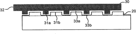
图4a示出了根据本发明具有竖直推动叠合锁定系统的镶板的一个实施例。短边缘4a和4b包括可位移榫舌30,该榫舌30与一个边缘上的位移凹槽40连接,且与相邻边缘上的榫舌凹槽20协作,以用于边缘的竖直锁定。可位移榫舌30和榫舌凹槽20包括凸起31a、31b和凹进33a、33b。可位移榫舌上的凸起31a水平地延伸到竖直平面VP和边缘的上部之外。短边缘还包括锁定条6,该锁定条具有在一个边缘上的锁定元件8,其与相邻边缘上的锁定凹槽协作,以用于边缘的水平锁定。镶板如下安装。将第一行R1中的第一镶板1”与第二行R2内的第二镶板1连接。将新镶板1’移动成使得其长边缘5a以约25-30度的正常安装角度向第一镶板1”的长边缘5b移动、压向相邻边缘和通过偏角调节将其长边缘5a与第一镶板的长边缘5b连接。这个偏角调节动作还将新镶板1’的短边缘4b与第二镶板1的短边缘4a连接。叠合镶板1’可以利用沿竖直平面VP的竖直和转动运动的结合和利用第二镶板1与新镶板1的顶边之间的接触而水平地锁定到条板1。上部榫舌凸起31a将在偏角调节过程中经过榫舌凹槽20上的凹进33b。边缘4a、4b在这个阶段没有竖直锁定,并且可以再次向上偏角。可位移榫舌30具有边缘部分,该边缘部分具有在第二镶板1的长边缘5b处暴露的挤压边缘32。当新镶板1’和第二镶板1平放在底层地板上时,该挤压边缘可以沿短边缘4a的接头侧向推动。可位移榫舌30可以基本与短边缘4a平行地位移,从而使上部榫舌凸起31a与下部榫舌凹槽凸起31b重叠,该重叠竖直地锁定相邻短边缘4a、4b。压力与接头平行,并且消除了边缘在锁定过程中分离的风险。整个压力可以用于在相同平面内锁定镶板,即使边缘在安装前有点扭曲。该锁定系统特别适合锁定具有尖锐边缘(没有斜面)的木质地板。Figure 4a shows an embodiment of a panel according to the invention with a vertically push-to-fold locking system. The
凸起和凹进可以用多种方法形成。可以使用锯片原理,其中优选地多个锯片形成凸起和凹进。也可以使用刀具原理,其中使用多个刀具,分别用于每个凹进。一种非常有效的方法是螺旋刀具原理。可以在连续生产线上用非常经济的方法和以很高的精度生产凸起和凹进,特别是在镶板位置与工具位置和工具转速精确地同步的情况下。仅在外部工具部分的有限部分上具有切割齿的大的旋转工具也可以用于形成凸起和凹进。其它方法是激光切割或冲压。所有方法都可以单独地使用或组合使用。The protrusions and recesses can be formed in a variety of ways. The saw blade principle can be used, wherein preferably a plurality of saw blades form the protrusions and recesses. It is also possible to use the tool principle, in which several tools are used, one for each recess. A very effective method is the helical cutter principle. The protrusions and recesses can be produced very economically and with great precision on a continuous production line, especially if the position of the paneling is precisely synchronized with the position of the tool and the rotational speed of the tool. A large rotary tool with cutting teeth on only a limited portion of the outer tool part can also be used to form the protrusions and recesses. Other methods are laser cutting or stamping. All methods can be used individually or in combination.
图4b示出了从上面看去处于解锁位置的可位移榫舌30。榫舌凸起31a竖直地位于凹槽凹进33b的上方。图4c示出了当侧向压力P移动可位移榫舌30使榫舌凸起和凹槽凸起31a、31b相互重叠时的锁定位置。Figure 4b shows the
锁定系统可以仅用榫舌上的一个凸起31a和榫舌凹槽31b以及榫舌凹槽上的一个凹进33b形成。然而优选地,榫舌和榫舌凹槽包括多个凸起和凹进,它们优选地沿接头边缘形成,并且相互之间具有基本相同的间距。凸起应优选地基本相同。凹进也应优选地基本相同。它们应比凸起大并匹配于凸起的间距。The locking system can be formed with only one
图5a示出了根据本发明的锁定系统的剖面。位移凹槽40可以制成比在现有技术的系统中小得多,因为不要求竖直位移。足够的锁定强度可以利用例如具有为地板厚度FT的约0.5倍或甚至更小的槽深GD的位移凹槽和具有为地板厚度FT的约0.5倍或更小的槽深GD’的榫舌凹槽实现。作为非限制性示例,榫舌宽度TW优选地可以是约5-6mm。这意味着榫舌的宽度可以小于地板厚度。榫舌厚度TT可以是地板厚度的约0.2倍或甚至更小。作为非限制性示例,榫舌厚度TT优选地可以是约1.5mm。这使得锁定系统非常适合于竖直地(D1)和水平地(D2)锁定具有5-10mm厚度的薄的地板镶板。已经利用具有小于5mm的宽度和小于1mm的厚度的可位移榫舌获得牢固的锁定。也已经生产出了具有深度分别少于2mm的位移凹槽和榫舌凹槽的实施例。Figure 5a shows a section through a locking system according to the invention. The
图5b示出了从上面看去处于解锁位置的可位移榫舌30。在这种解锁位置,榫舌凸起31a竖直地定位在凹槽凹进33b的上方。在这个实施例中,大部分凸起优选地是相同的,并且从中心到中心测量的间距34基本是相同的。优选的距离是地板厚度的约1-2倍。已经利用具有约10mm间距的凸起实现了牢固的锁定。图5c示出了当优选地作用在可位移榫舌32的凸起的边缘部分32上的侧向压力P沿接头移动可位移榫舌30使榫舌凸起和凹槽凸起31a、31b相互重叠时的锁定位置。位移应优选地与凸起35的长度大约相同。已经利用具有约4mm长度的凸起实现了牢固的锁定。可位移榫舌30可以优选地与位移凹槽40通过很多方法连接,例如优选地利用柔性的摩擦连接件36、利用蜡或仅利用榫舌与凹槽之间的摩擦。摩擦连接件36在所示实施例中作为柔性接片(tap)形成,该柔性接片产生作用于位移凹槽40的上部或下部的竖直压力。这种摩擦连接件提供了这样的优点,即,可位移榫舌30以可靠的方式固定在位移凹槽40内,即使凹槽开口在生产过程中发生变化。这种摩擦连接允许在预定摩擦力下实现位移。Figure 5b shows the
图6a-6h用四个步骤示出了根据本发明的短边缘的一部分的锁定。新镶板1’的短边缘在该实施例中竖直地向第二镶板1移动,如图6a-b所示。榫舌凸起31a与凹进33b匹配,它们关于凹槽凸起31b错位且定位在凹槽凸起31b下方的平面内。进一步竖直移动将使榫舌凸起31a进入凹槽凹进33b,当然也使凹槽凸起31b进入榫舌凹进33a。图6e-f示出了当镶板1、1’已经竖直地连接和平放在底层地板上的相同平面内时的位置。图6g-h最后示出了竖直锁定位置,其中凸起31a、31b由于可位移榫舌30沿接头边缘的位移而相互重叠。Figures 6a-6h illustrate the locking of a part of the short edge according to the invention in four steps. The short edge of the new panel 1' is in this embodiment moved vertically towards the
这种安装方法和锁定系统还在图7a-7d中进一步说明。图7a示出了如何能利用侧压力P使挤压边缘32沿接头移动,所述侧压力P是在安装新一行时在长边缘5a的偏角调节过程中由长边缘榫舌10产生的。该位移在起始步骤中主要由长边缘榫舌10的线性位移导致,直到长边缘5a、5b的上部彼此接近,优选地彼此接触。图7b示出了可位移榫舌30处于其最终的锁定位置的锁定位置。最终锁定利用转动动作完成,该转动动作进一步移动榫舌10的末端和可位移榫舌30进入长侧边缘的榫舌凹槽9中。该锁定距离LD可以在例如地板厚度FT的0.05-0.15倍之间变化,这取决于榫舌10的末端和挤压边缘32的形状。锁定元件8和锁定凹槽14通常在该偏角调节和移动步骤的大部分中是接触的。长边缘5a上的榫舌10在该最终锁定步骤中会产生作用于挤压边缘32的相当大的压力,短边缘4a、4b可在竖直方向上牢固地靠着彼此锁定。图7c示出了第二镶板1和新镶板1’在它们的短边缘4a、4b竖直地锁定之前的位置,图7d示出了当第三镶板1a的榫舌10已经将可位移榫舌30移动到其最终锁定位置时的锁定位置。This mounting method and locking system is further illustrated in Figures 7a-7d. Figure 7a shows how the
很明显,榫舌可以利用作用于挤压边缘32的压力P移动,该压力P由安装人员在安装过程中使用例如工具施加,而不是由第三镶板的偏角调节施加。还明显的是,可位移榫舌30可以与镶板的边缘在安装过程中连接。It is clear that the tongue can be moved with a pressure P on the extruded
图8a-8b示出了地板块的锁定和根据竖直推动叠合原理的锁定,该地板块在此处是木质地板。在这个实施例中,可位移榫舌30固定在地板块上,使得其末端大约位于一个长边缘5a的榫舌侧10的上边缘处,并使其挤压延伸部32突出到另一长边缘5b的凹槽侧9之外。这在图8a、8c和8d中示出。如图8e所示,第三镶板1a利用向第二镶板1的偏角调节而连接,其榫舌10压靠可位移榫舌30的挤压边缘32。图8f示出了榫舌30如何移动,其中其一个边缘部分Es1与第一镶板1”的长边缘凹槽9的内部间隔开,而另一边缘部分——挤压边缘32——与第三镶板1a的榫舌10的末端接触。这种安装原理使得,取决于可位移榫舌的起始位置,地板可以在两个方向上安装——长边缘榫舌部分在(锁定)条上或长边缘(锁定)条在榫舌下方。应提及,约0.5-3mm的位移可以得到非常牢固的锁定。Figures 8a-8b show the locking of floorboards, here a wooden floor, and the locking according to the vertical push-to-fold principle. In this embodiment, the
图9a-9d示出了根据本发明第一方面的实施例,其中利用镶板沿短边缘的位移实现短边缘的竖直锁定。榫舌上和榫舌凹槽上的凸起31a、31b和凹进33a、33b可以与镶板芯部制成一个整体,或者用与镶板连接的单独材料制成。图9d示出了(锁定)条6和其锁定元件8包括凸起和凹进的实施例。这种实施例可用于简化榫舌凸起31a的生产,因为可以使用能在形成榫舌凸起31a时切穿(锁定)条6的工具。Figures 9a-9d show an embodiment according to the first aspect of the invention, wherein vertical locking of the short edges is achieved by displacement of the panels along the short edges. The
图10a-c示出了具有固定和不可位移的凸起31a、31b的实施例的安装。新镶板1’的短边缘4b优选地利用竖直移动与同一行内的第二镶板的相邻短边缘4b连接,使得凸起31a经过凹进33b,且边缘被水平地锁定。短边缘4a、4b然后相对于彼此和在水平锁定位置沿相邻边缘移动,使得长边缘5a、5a’如图10b所示沿相同的直线对齐并竖直地和水平地锁定,由此使凸起31a、31b相互重叠。两个镶板1、1’的长边缘5a、5a’随后优选地利用偏角调节与第一镶板1”连接,如图10c所示。Figures 10a-c illustrate the installation of an embodiment with fixed and
图11a-11c表明,这种连接可以在第一镶板1”和第二镶板1位于靠着彼此偏角的位置时和在它们的长边缘的上部接触时实现。然后新镶板1’的短边缘利用竖直运动与第二镶板的相邻短边缘连接,该第二镶板处于相对于底层地板的偏角位置,方法与图10a所示的相同。然后新镶板1’在偏角位置移动,且其短边缘与第二镶板1的短边缘连接,直到其长边缘接触第一镶板1”的长边缘。然后新镶板1’和第二镶板1向下偏角,新镶板1’竖直和水平地与第一镶板1”和第二镶板1机械锁定。Figures 11a-11c show that this connection can be achieved when the
上述安装方法的优点是,短边缘可以不用任何偏角调节而连接和水平锁定。这在镶板很长或在不可能使用偏角调节的拐角内或门周围进行安装时是有利的。The advantage of the above installation method is that the short edges can be connected and locked horizontally without any angling adjustment. This is advantageous when the panels are long or when installing in corners or around doors where angling is not possible.
图12a-12f表明,能够对竖直运动进行锁定的短边缘上的凸起的形成的基本原理也可以用于在长边缘5a、5b上形成凸起37a、37b和凹进38a、38b,这使得能够对一个长边缘向另一相邻长边缘的水平运动进行锁定。图12e和12f和12a示出了两个长边缘5a和5b可以水平地在相同平面内连接和竖直地相互锁定,使得条板5b的凸起37a与槽板5a的凹进38b配合,而槽板5a的凸起37b与条板5b的凹进38b配合。然后长边缘5a、5b可以沿长边缘位移,使得所述凸起水平地相互重叠,其中一个凸起定位在另一凸起的后面,且它们水平地锁定边缘,如图12a所示。Figures 12a-12f show that the basic principle of forming protrusions on the short edges to lock vertical movement can also be used to form
图13a-13e详细地示出了具有如图12a-12f所示的长边缘锁定系统的地板镶板的安装。如图13a和13b所示,两个长边缘5a和5b在相同平面内水平地连接和竖直地相互锁定,使得条板5b的凸起37a与槽板5a的凹进38b配合,而槽板5a的凸起37b与条板5b的凹进38a配合。然后长边缘5a、5b沿彼此位移,使得凸起相互重叠并水平地锁定边缘。短边缘4a和4b可以通过水平卡锁锁定,优选地利用如图13d所示的包括柔性锁定元件8’的卡锁系统。这种安装方法可以用于锁定在两个相对侧上都具有装饰表面的双面镶板,如图13f所示。Figures 13a-13e show in detail the installation of floor panels with the long edge locking system as shown in Figures 12a-12f. As shown in Figures 13a and 13b, the two
图14a和14b表明,有必要在两个地板块用其短边缘连接时使长边缘上的凸起37a、37b和凹进38a、38b沿边缘以产生非常确定的样式的方式进行分布,优选地具有相同间距,并且这种样式对应于单个镶板上的主要样式。根据这个优选实施例的地板块的特征在于,两个相连地板块1a、1”的相邻凸起37a’、37a”的间距与两个地板块1a或1”其中之一的两个凸起37a”、37a的间距基本相同。图14c示出了已经沿接头位移且与第一行的两个相连地板块1a、1”竖直和水平地锁定的第二地板块1。图14d和14e示出了第二行的新镶板1’的长边缘如何利用向第一行的第一镶板1”的长边缘的水平移动、沿所述长边缘滑动和最终利用与相同的第二行内的第二镶板1的相邻短边缘的水平卡锁实现锁定。Figures 14a and 14b show that when two floorboards are joined by their short edges, it is necessary to distribute the
图15a-e示出了安装在长边缘上包括凸起的镶板的可选择的方法。图15a示出了第二行内的第二镶板1和新镶板1’的相邻短边缘可以利用例如偏角调节、水平卡锁或沿接头插入而竖直和水平地锁定。然后新镶板1’可以位移并与第一行内的第一镶板1”的相邻长边缘连接——假设第二镶板1未完全锁定。这将允许凸起与长边缘上的凹进配合。然后第二镶板1和新镶板可以沿连接好的长边缘位移并竖直和水平地锁定。Figures 15a-e illustrate an alternative method of mounting panels comprising protrusions on the long edges. Figure 15a shows that the adjacent short edges of the
图15b-e示出了替换安装方法。第二镶板1和新镶板1’的短边缘可以通过边缘的竖直或水平连接、然后通过沿短边缘位移使得凸起相互重叠和直到相邻长边缘的上部接触而实现锁定,如图15b-d所示。长边缘最终通过所述两个镶板1、1’沿在相邻行内安装的镶板的长边缘位移而锁定,这使得相邻长边缘凸起处于水平重叠位置,如图15e所示。Figures 15b-e illustrate alternative mounting methods. The short edges of the
长边缘可以形成为使得摩擦将边缘保持在一起直到整行都移动。凸起可以在长度方向上是楔形的,使得沿边缘的位移将自动地使边缘相互对齐和优选地相互压紧。利用插入在一行中的第一和最后一个镶板与相邻壁面之间的例如摩擦、胶合或柔性材料,可以避免各行在安装之后相对于彼此滑动。也可以使用与锁定系统集成的卡锁或产生摩擦的机械装置,该机械装置在纵向位置上锁定镶板和避免滑动。Long edges can be formed such that friction holds the edges together until the entire row is moved. The projections may be tapered in length so that displacement along the edges will automatically bring the edges into alignment and preferably against each other. With eg friction, glue or flexible material interposed between the first and last panels in a row and the adjacent wall, the rows can be prevented from sliding relative to each other after installation. It is also possible to use snap locks integrated with the locking system or friction-generating mechanisms that lock the panels in longitudinal position and prevent slippage.
图16a-16c表明图9和12所示的实施例可以组合,并表明包括配合的凸起31a、31b和凹进33a、33b的相邻短边缘可以利用竖直和/或水平运动连接和利用沿相邻边缘的位移竖直和水平地锁定,使得凸起31a、31b相互重叠且竖直地锁定相邻边缘,而锁定元件8进入锁定凹槽14且水平地锁定相邻边缘。根据图15b-15d,这种锁定系统可以用于锁定短边缘。Figures 16a-16c show that the embodiments shown in Figures 9 and 12 can be combined and show that adjacent short edges comprising
图17a-17e示出了根据刀具原理形成凹进33b和凸起31b的生产方法。可以使用多个刀具70,分别用于每个凹进。这个原理可以在长边缘和短边缘上用于榫舌和/或榫舌凹槽侧。该成形可以在外形切割之前或者之后发生。Figures 17a-17e show a production method for forming
图18a-e示出了也可用锯片原理实现上文所述的成形,其中优选地在相同轴线上的优选地多个锯片71形成凸起31b和凹进33b。Figures 18a-e show that the above-described forming can also be achieved with the saw blade principle, wherein preferably a plurality of
图19a-19e示出了用螺旋刀具原理形成上文提及的凸起31b和凹进33b的方法。这种成形可以在连续生产线上用非常经济的方法和以很高的精度实现,特别是在镶板位置与工具位置和工具转速精确地同步的情况下。螺旋刀具72可以作为单独的设备使用,或更优选地作为在双端式制榫机上的集成的工具位置使用。其可以具有单独的控制系统,或更优选地(具有)与双端式制榫机的主控制系统65集成的控制系统。边缘基本与螺旋切割工具72的旋转轴线AR平行地位移。生产具有圆化的或尖锐部分的任意形状是可能的。切割可以在外形切割之前、之后或与其相关地发生。在形成短边缘时,优选地当长边缘和至少短边缘锁定系统的主要部分已经成形时用该方法作为最终步骤之一。在一些实施例中,优选地在榫舌凹槽20成形之前在凹槽侧形成凸起和凹进。这减少了凹进和凸起的内壁上的散落纤维和碎片的量。Figures 19a-19e illustrate a method of forming the above-mentioned
在镶板边缘上形成的凹进33b的长度方向上的位置取决于与镶板边缘接触的第一进入工具齿56a的位置,如图19c所示。这意味着工具的旋转必须匹配于向工具移动的镶板边缘。可以通过测量传送链或传送带或移动该链或带的致动装置的速度来实现这种匹配。这在形成短边缘时是适合的,因为(传送)链通常使用以非常精确的间距定位的链钩(chain dog)移动镶板。作为替换,可以通过在镶板接近螺旋切割工具时测量镶板位置来实现该匹配。该替换方案可以在例如加工长边缘时使用。The position along the length of the
所示螺旋切割工具72的直径53应优选地在入口侧ES小于在相对的出口侧。然而螺旋切割工具也可以在整个长度54上具有相同的直径53。在这种工具配置下,增加的切割深度可以利用相对于镶板边缘的进给方向略微形成角度的旋转轴线实现。The
工具配置的螺距54限定了凹进和凸起的间距。因此非常容易利用在接头的相当大长度上的非常精确的间距形成大量凹进和凸起。The
螺旋刀具的齿56应优选地用工业金刚石制成。工具直径53优选地是约50-150mm,工具长度54优选地是约30-100mm。每个齿应优选地具有0.05-0.2mm的切割深度。The
图20a-c示出了螺旋刀具72的示例,该螺旋刀具设计成用于在具有HDF材料的芯部的6-10mm厚的层压地板边缘形成凹进和凸起。该工具包括32个齿56,每个齿具有0.1mm的切割深度,允许形成具有3.2mm壁面的凹进。螺距是10mm,齿定位在5个螺旋行内。直径53是80mm,长度54是50mm。转速是约3000转每分钟,这意味着进给速度可以是3000*10=30,000mm/min或30米每分钟。如果转速增加到4000转,则进给速度可以增加到40米。螺距可以增加到20mm,这可以将进给速度进一步增加到80米/分钟。该螺旋刀具可以容易地满足55米/分钟的传统的进给速度,通常用于短边缘锁定系统的生产中。当在短边缘上形成三维凹槽时,如果需要,螺旋切割工具还可以设计成允许200米/分钟的进给速度。Figures 20a-c show an example of a
螺旋刀具可以具有多于一个入口56a和双排螺旋齿,这可以显著增加进给速度。The helical cutter can have more than one
根据本发明,凹进相对于边缘拐角的位置可以制成具有少于1.0mm的公差,这足以形成高质量的锁定系统。According to the invention, the position of the recess relative to the edge corner can be made with a tolerance of less than 1.0 mm, which is sufficient to form a high quality locking system.
链钩之间的间距恰好被螺距除是有利的。链钩之间300mm和10mm螺距意味着,为了到达相同位置,螺旋刀具应转动刚好30圈。这意味着,为了到达正确位置和克服最终生产偏差,仅需要对螺旋切割工具进行小的调整。It is advantageous if the distance between the chain hooks is exactly divided by the thread pitch. The 300mm and 10mm thread pitch between the chain hooks means that in order to reach the same position, the helical cutter should be turned exactly 30 times. This means that only small adjustments to the helical cutting tool are required to get to the correct position and to overcome final production deviations.
图20d示出了8mm层压地板的表面转向下的边缘部分1’,该边缘部分用图20a-c所示的螺旋刀具72形成。凸起31b和凹进33b在榫舌凹槽20的下唇部22上成形。凹进33b的内部部分小于外部部分,且具有与工具齿相同的几何形状。如果齿在工具中移动或者如果工具转动没有完全匹配于镶板的进给,则凹进可以大于齿。然而间距将仍保持相同。Fig. 20d shows a surface-turned-down edge portion 1' of an 8mm laminate flooring, formed with the
从未用于地板生产的螺旋刀具原理开创了特别是在长边缘上形成具有非连续和非平行的三维形状的新的锁定系统的可能性。这个新的生产方法使得以非常合理和成本有效的方式生产上述包括凸起和凹进的锁定系统成为可能。该原理还可以用于生产在长度方向上具有变化的装饰性凹槽和斜面。The spiral cutter principle, which has never been used in floor production, opens up the possibility of forming new locking systems with non-continuous and non-parallel three-dimensional shapes especially on long edges. This new production method makes it possible to produce the above-mentioned locking system comprising protrusions and recesses in a very rational and cost-effective manner. This principle can also be used to produce decorative grooves and bevels that vary along their length.
图21a-b表明,凸起的成形可以在外形切割之前发生。具有凸起31a和凹进33a的单独材料62或镶板芯部可以与地板块的边缘连接,并优选地胶合在木质或层压地板的表面层60与平衡层61之间。前述生产方法中的任一个都可以用于形成凸起。Figures 21a-b demonstrate that shaping of the protrusions can occur prior to profile cutting. A
图21c示出了凸起和凹进可以用类似锯片的大的旋转工具73成形,该工具仅在工具本体的一部分上包括切割齿。这是螺旋刀具原理的简单变型,每次转动形成一个凹进。优点在于,凹进之间的间距可以通过工具转速或镶板的进给速度的调整而改变。然而要达到高速和足够的公差是更困难的。大的直径在多种应用中还可能是缺点。Figure 21c shows that the protrusions and indentations can be formed with a
图22a-f示出了用于插入和固定单独部分、优选地将可位移榫舌30插入和固定到镶板、优选是地板镶板的边缘中的插入装置59和方法。使包括多个柔性榫舌30的榫舌坯料TB从堆垛装置58向分离装置57位移,在该分离装置中,可位移榫舌30与榫舌坯料TB分离并优选地竖直位移到一较低平面(图22a、22b),在该较低表面处,推动器46将可位移榫舌30压入镶板边缘上的位移凹槽40中(图22d)。新的榫舌可以随后与坯料分离,如图22e-f所示。插入装置59应优选地与加工和形成机械锁定系统的双端式制榫机(未示出)集成。这个原理的第一优点是可以使用相同的链或传送装置来移动和定位地板块的边缘。第二优点是可以使用相同的控制系统65来控制插入装置和双端式制榫机。第三优点是可以调整链和链钩,使得链钩的间距非常确定,并且优选地这将帮助实现将单独部分精确和简单地固定在凹槽中。第四优点是比使用具有两个单独控制系统的两个单独设备的情况低得多的投资成本。该设备和生产方法可以用在包括单独部分的所有锁定系统中,而不仅是所述实施例。Figures 22a-f show an
本发明提供了具有插入边缘中的单独部分的锁定系统的生产设备。该设备包括:具有移动镶板的传送装置的双端式制榫机,具有插入单独部分的推动器46的插入装置59,和控制系统65。插入装置与双端式制榫机集成为一个生产单元,推动器和传送装置与控制传送装置和推动器的同一控制系统连接。The invention provides a production device with a locking system of a separate part inserted in the edge. The equipment comprises: a double-ended tenoner with a conveyor for moving the panels, an
图23a-23d示出了单独榫舌或任意相似的松动元件的连接。根据上述方法,可位移榫舌30利用推动器连接在边缘的凹槽40中。推动器可以优选地连接整个榫舌或仅连接榫舌的一个边缘。图23b示出了可以使用压力轮PW将可位移榫舌30进一步连接到凹槽40中。图23d示出了可以使用定位装置PD将榫舌相对于一个长边缘定位。这可以在连续生产线中有序进行。Figures 23a-23d illustrate the connection of a single tongue or any similar loose element. According to the method described above, the
图23e示出了如何能用榫舌坯料TB、例如用挤出部分形成可位移或柔性榫舌30,该挤出部分被冲压以形成榫舌和使榫舌与挤出的榫舌坯料TB分离。可以例如通过冲压或利用加热形成摩擦连接。可位移榫舌还可由基于木纤维的材料例如HDF、胶合板、硬木等形成。任意类型的材料都可以使用。Figure 23e shows how a displaceable or
图24a、b示出了其中凹槽20的下唇部22及其凸起和凹进由与边缘连接的单独材料制成的实施例。锁定系统可以包括可位移榫舌30和/或可位移下唇部22。很明显,榫舌30可以与凸起和凹进制成一个整体,只有下唇部可以是可位移的。图24c示出了所有针对竖直锁定所描述的原理都可以用于水平地锁定地板块。具有竖直延伸的凸起和凹进的单独锁定元件8’可以与包括相似凸起和凹进的锁定元件8组合。锁定元件8’或镶板边缘可以为了水平地锁定镶板而移动,其中重叠的凸起在彼此后面锁定。图中示出了具有用于竖直锁定的柔性榫舌30的实施例。很明显,可以使用传统的整体式榫舌。Figures 24a,b show an embodiment in which the
图25a和25c示出了处于解锁位置的可位移榫舌30的实施例,图25b和25d示出了处于锁定位置(的可位移榫舌30)。榫舌凸起31a可以是楔形的或圆形的,榫舌凹槽凹进33b也可以具有各种形状,例如矩形、圆形等。圆形或楔形的凸起有助于锁定,因为重叠可以在位移过程中逐步实现。Figures 25a and 25c show an embodiment of the
图26a-b示出了榫舌凸起可以具有下接触表面34,该表面向上倾斜至水平面。该下表面可以在位移过程中将凹槽凸起31b和边缘压靠在条6的上部,以牢固地竖直锁定边缘。凹槽凸起31b还可以形成为具有竖直倾斜的壁。Figures 26a-b show that the tongue protrusion may have a
图26c-e示出了单独榫舌30可以包括钩部35,该钩部35在竖直卡锁叠合过程中自动地卡锁和抓靠凹槽凸起31b的上部。该钩部可以竖直地或水平地延伸和弯曲。Figures 26c-e show that the
发明人实施的多个试验表明,大的竖直或水平载荷可以导致条板1上的开裂C,如图27a所示。这种开裂主要在榫舌凹槽20的下部与锁定凹槽14的上部之间发生。这个问题主要涉及具有低抗张强度的具有相当软的芯部的地板和薄的地板。通常不推荐仅通过向上移动位移凹槽40’和榫舌凹槽20’的位置来解决这种问题,因为这将在条板1中产生薄的和敏感的上唇部22。Several tests carried out by the inventors have shown that large vertical or horizontal loads can lead to cracks C on the
图27b表明该问题可以利用在凹槽侧上包括凸起7的锁定系统解决。该几何特征允许条侧1上的多个主要水平延伸的表面例如下接触表面6a、上位移凹槽表面40a和下位移凹槽表面40b都可以用相同的工具成形,并且这可以减少生产偏差。Figure 27b shows that this problem can be solved with a locking system comprising a
图27c示出了该问题还可以利用包括相对于彼此竖直错位的位移凹槽40和榫舌凹槽30的锁定系统来解决。位移凹槽40优选地位于一个镶板边缘(1)中的第一水平面H1内,榫舌凹槽位于另一镶板边缘(1’)中的第二水平面H2内。第二水平面H2定位成比第一水平面H1更接近镶板的正面。图27d示出了可以用在具有错位的凹槽的锁定系统中的可位移榫舌30。Figure 27c shows that this problem can also be solved with a locking system comprising a
图27e示出了具有可位移榫舌30的锁定系统,该榫舌30具有位于水平锁定平面LP下方的部分,该水平锁定平面与锁定元件8的上部相交。这提供了更牢固的锁定。这种位移凹槽可以用传统方法生产,利用以不同角度工作的多个工具或利用刮削(scrap ing)或拉削(broaching)。FIG. 27e shows a locking system with a
图27f示出了该原理还可以经过一些改动用在现有技术的锁定系统中,其中柔性榫舌30主要垂直于边缘利用竖直卡锁或侧推从一个凹槽向相邻榫舌凹槽内移动。Figure 27f shows that this principle can also be used with some modifications in prior art locking systems where the
图28a-28e示出了另一实施例,其中可位移榫舌30在竖直卡锁叠合过程中自动地位移,使得可位移榫舌凸起和榫舌凹槽凸起相互重叠。可位移榫舌包括柔性边缘部分32a,该柔性边缘部分在叠合过程中如图28b所示被压紧。当镶板边缘在同一平面内时,边缘部分32a将可位移榫舌30向起始位置压回并锁定边缘,如图28c所示。柔性边缘部分还可形成为柔性连接件32b,其拉回可位移榫舌并锁定边缘。这些原理可以单独使用或组合使用。图28d和28e示出了榫舌的楔形表面和榫舌凹槽凸起31a、31b如何在叠合过程中协作并移动可位移榫舌,使其能够弹回和竖直地锁定。这种楔形表面还可以用于在叠合过程中定位榫舌和克服生产偏差。Figures 28a-28e show another embodiment in which the
图29a-e示出了侧推的替换方案,在两个镶板处于同一平面内时,可以用转动动作锁定两个镶板1、1’的相邻边缘。这种锁定可以不需要任何卡锁阻力和使用有限的分离力而实现。图3a和29b示出的已知的转动卡锁榫舌30可以包括可用于转动榫舌30和锁定边缘的转动延伸部38,如图29c所示。锁定系统还可以包括两个单独部分39、30,其中一个内部部分39具有一截面,使得当转动延伸部竖直地向下转动时,宽度W将增加并将榫舌30推入相邻凹槽。榫舌的位移还可以利用朝向长边缘的水平转动而实现。Figures 29a-e show an alternative to side push, whereby adjacent edges of two
图30a-30d示出了具有可位移榫舌(30)的锁定系统,该榫舌根据上述实施例竖直地(D1)锁定边缘,但是当可位移榫舌30沿接头位移使得凸起相互重叠时也水平地(D2)锁定边缘。可位移榫舌具有至少两个锁定元件,每个镶板边缘具有至少一个优选地与镶板芯部成形为一个整体的锁定元件。可位移榫舌30根据图30a示出的实施例包括两个榫舌锁定元件42a、42b。位移凹槽40和榫舌凹槽20也具有与镶板制成一个整体的凹槽锁定元件43a、43b,当凸起31a、31b相对于彼此位移使得其如图8a-c所示相互重叠时,该凹槽锁定元件与榫舌锁定元件协作并水平地锁定相邻边缘。图30a按比例绘制并示出了6.0mm的层压地板。锁定系统用大的旋转工具生产。为有助于这种生产,锁定系统包括下唇部边缘48a、48b,其具有斜角部分、与可位移榫舌相邻、向外和向下延伸并位于与锁定元件42a或42b相对的榫舌表面上。由于该锁定系统在后侧不具有带锁定元件和锁定凹槽的条,因此生产这种竖直推动叠合系统是可能的,即使是在非常薄的地板镶板中。图30d示出了锁定元件42a、42b、43a、43b具有基本竖直的锁定表面47的实施例,这些表面与水平面具有约90度角。下唇部边缘48a、48b基本是竖直的。这种锁定系统可以具有高的竖直和水平锁定强度。锁定表面应优选地与水平面超过30度。45度和更大是更优选的。Figures 30a-30d show a locking system with a displaceable tongue (30) that locks the edge vertically (D1) according to the above embodiment, but when the
图31a-31e示出了锁定系统的不同实施例,其中可位移榫舌竖直和水平地锁定。图31a示出了具有包括三个锁定元件42a、42b、42c的可位移榫舌的锁定系统。Figures 31a-31e show different embodiments of locking systems where the displaceable tongue is locked vertically and horizontally. Figure 31a shows a locking system with a displaceable tongue comprising three locking
图31b示出了具有下唇部48、49的锁定系统,这些下唇部竖直地相互重叠并在一个竖直方向上锁定边缘。可位移榫舌30可以设计成使得其产生朝向重叠的下唇部48、49的压力,这可以改进生产公差和竖直锁定强度。Figure 31b shows a locking system with
图31c示出了在每个相邻镶板边缘的下部具有两个锁定元件42a、43a和42b、43b的锁定系统。该锁定系统类似于将图8a上下颠倒。Figure 31c shows a locking system with two locking
图31d示出了具有八个锁定元件42a、42b、42a’、42b’、43a、43b、43a’、43b’的锁定系统。可位移榫舌可以利用基本水平的卡锁与边缘连接。图31e示出了具有三加三个锁定元件的类似的锁定系统。Figure 31d shows a locking system with eight locking
很明显,所有这些锁定原理都可以相组合。一个边缘可以例如具有根据图31a的锁定,另一(边缘具有)根据图31d或31e(的锁定),所有锁定系统都可以具有重叠的下唇部。It is obvious that all these locking principles can be combined. One edge may eg have a locking according to Fig. 31a, the other (with a locking) according to Fig. 31d or 31e, all locking systems may have overlapping lower lips.
图30a-d和31a-e中所示的整体式锁定元件包括具有成形为切口凹槽的内部部分的锁定元件。而图32a-c表明,整体式锁定元件43a、43b也可以形成在镶板的背面上而不是在凹槽内。这简化了生产。然而,榫舌锁定元件42a、42b的内部部分在这个实施例中形成为切口凹槽。榫舌30可以通过例如机加工、注塑或挤出进行生产,这些生产方法在必要时可以与冲压组合。榫舌30可以成形为具有很多不同的截面,例如具有在下唇部中在上唇部之外延伸的锁定元件,如图32d所示。这种实施例更容易生产,因为镶板边缘或榫舌中不包括任何切口凹槽。这种可位移榫舌30可以利用偏角调节、卡锁或沿边缘插入而与边缘连接。The one-piece locking elements shown in Figures 30a-d and 31a-e include locking elements having an inner portion shaped as a cutout groove. Figures 32a-c, however, show that the
图33a-c示出了可位移榫舌可以布置在槽板1’上,使得其锁定在位于条6的外部部分上的凹槽内。Figures 33a-c show that a displaceable tongue can be arranged on the channel plate 1' such that it locks in a groove on the outer part of the
图34a-d示出了生产图8a-c所示的锁定系统中的锁定元件43a的生产方法。第一工具位置T1可以例如形成水平凹槽。下一工具位置T2可以形成切口凹槽40a,最后在第三工具位置T3的精细刀具可以形成边缘的上部。Figures 34a-d illustrate a production method for the
图35a-c示出了如何能够生产根据图31b的锁定系统。水平凹槽通过例如旋转工具T1成形。在该实施例中具有竖直锁定表面的切口凹槽40a可以具有任意角度且可以利用拉削成形,其中镶板相对于固定工具移动,该工具像具有多个小的和略微错位的工具刃的刀一样切割。Figures 35a-c show how the locking system according to Figure 31b can be produced. The horizontal grooves are formed, for example, by a rotary tool T1. The
图36a-d示出了一种将可位移榫舌30插入位移凹槽40中的方法,使得榫舌平行于凹槽和沿凹槽插入。该方法可以用于任意榫舌,但特别适合于具有锁定元件的可位移榫舌。榫舌30优选地与榫舌坯料分离并移动到与位移凹槽成一直线的位置,在该处,其通过一个或多个榫舌保持件44a、44b保持在预定位置。镶板1与可位移榫舌基本平行地移动,边缘部分插入位移凹槽40,并优选地通过一个或多个引导单元45a、45b进一步压入凹槽。可位移榫舌优选地通过镶板边缘从榫舌保持件44a、44b释放,该镶板边缘导致保持件例如从边缘转动离开。Figures 36a-d show a method of inserting a
图37a-c示出了一种将榫舌插入凹槽的方法,使得榫舌基本竖直地卡锁在凹槽内。整个榫舌或仅榫舌的一部分可以利用卡锁插入,其中推动器46将榫舌30的边缘压入凹槽40的一部分。榫舌的剩余部分可以利用上述方法沿接头插入。卡锁连接可以通过如图37b所示的镶板边缘上的柔性唇部实现和/或通过如图37c所示的榫舌30上的柔性唇部实现。Figures 37a-c show a method of inserting the tongue into the groove such that the tongue snaps into the groove substantially vertically. The entire tongue or only a part of the tongue can be inserted with a snap lock, wherein the
图38a和38b表明,根据本发明的锁定系统可以被锁定成使得镶板边缘基本水平地朝向彼此移动。然后它们可以利用侧推被锁定。该锁定系统还可以仅利用卡锁被锁定——如果可位移榫舌在锁定之前布置在使凸起相互前后对齐的位置。这种安装可以在例如镶板不可能偏角调节时使用。图38c示出了锁定元件42a’、43a’可被用于代替摩擦连接和用于在安装过程中将榫舌保持在凹槽40内。Figures 38a and 38b show that the locking system according to the invention can be locked such that the panel edges move substantially horizontally towards each other. They can then be locked using a side push. The locking system can also be locked only with a snap if the displaceable tongue is arranged before locking in a position where the projections are aligned front-to-rear with each other. This installation can be used, for example, when angling of the panels is not possible. Figure 38c shows that locking elements 42a', 43a' can be used instead of a frictional connection and to hold the tongue in the
图39a-d示出了将单独元件、优选地将榫舌连接在凹槽内的另一方法。如果榫舌30可以竖直地朝向镶板边缘输送和与水平推动器连接则是有利的。问题在于,某些榫舌、特别是具有相当复杂的三维形状的可位移榫舌和柔性榫舌仅可以被生产成具有一截面,该截面具有主榫舌平面TP,该主榫舌平面定义为榫舌将被水平地定位在一凹槽中的平面,该凹槽定位在与榫舌坯料TB的主平面相同的平面内。这个问题可以用下面的方法解决。榫舌坯料TB根据本发明被基本竖直地、或基本垂直于镶板1的位置朝向转动单元50定位和移动,如图39a所示。榫舌与转动单元50连接并与榫舌坯料分离,如图39b所示。然后转动单元50转动约90度,以使榫舌30以其主榫舌平面TP进入水平位置,使得其可以通过推动器46连接在镶板1边缘的凹槽40内,该推动器46将榫舌30从转动单元推出并推进凹槽40。这在图39c和39d中示出。镶板1被示出处于正面朝下的水平位置。Figures 39a-d show another method of connecting a separate element, preferably a tongue, in a groove. It is advantageous if the
具有凸起的可位移榫舌30可以有相当简单的截面并可以容易地制造成具有与榫舌坯料TB的主平面垂直的主榫舌平面TP和截面。这在图40a中示出。这样,在凹槽内的连接很简单,并且可以容易地将榫舌30推进凹槽40中,如图40a所示。The
图40b表明,与榫舌坯料TB连接的任意类型的榫舌30可以在与榫舌坯料TB分离之前和在连接到凹槽40中之前被转动。这种转动可以例如利用压在榫舌30的上部和下部的两个转动推动器51a、51b实现。FIG. 40 b shows that any type of
图40c示出了具有相当复杂的截面的榫舌,该榫舌制造成具有垂直于榫舌坯料的主平面的主榫舌平面TP和截面。榫舌30利用卡锁连接。图40d表明,如果榫舌在内部部分和外部部分具有凸起31a、31a’,则这种复杂的截面可以利用注塑生产。Figure 40c shows a tongue with a rather complex cross-section manufactured with a main tongue plane TP and a cross-section perpendicular to the main plane of the tongue blank. The
图41a表明,如果使用上部引导装置52a和/或下部引导装置52b,则榫舌30可以非常受控的方式被插入凹槽40中。凹槽40必须被定位成使得,其为上部引导装置52a在锁定元件8与位移凹槽40之间的定位提供空间。镶板在该图中是平的且正面向下示出。Figure 41a shows that the
图41b表明,如果榫舌30被插入到不与水平面平行的平面内,则可以为引导装置提供更大空间。Figure 41b shows that more space can be provided for the guide if the
图41c、41d、41e表明,如果条6和/或榫舌30和/或凹槽40的锁定元件8的一部分被去除,使得榫舌边缘可在更小阻力或优选地甚至没有任何阻力的情况下被插入凹槽40的一部分中,则会有利于榫舌边缘30a向凹槽40内的插入。然后榫舌30的剩余部分可以沿接头插入。Figures 41c, 41d, 41e show that if a part of the
图42a表明,具有包括凸起31a的多个可位移榫舌30的榫舌坯料TB可以通过冲压片状材料成形,该片状材料优选地包括HDF、密实层压材料、胶合板、木材或铝或任意类似材料。图42b表明,冲压可以用于将材料压紧和用于形成例如楔形凸起31a的三维截面。Figure 42a shows that a tongue blank TB with a plurality of
在薄地板或软芯部材料中使用单独或柔性榫舌可能是有利的,该榫舌如图27b所示靠着上部和下部榫舌凹槽表面锁定,并具有包括基本水平的上部和下部接触表面的凸起部分30a。这个原理还可以用在使用竖直卡锁叠合方法的现有技术的已知系统中。柔性榫舌30可以形成为具有突出部30a,该突出部靠着上部和下部榫舌凹槽表面21a和20b锁定,如图43a-43c所示。具有这种榫舌的锁定系统可能很难或不能用图43d所示的竖直运动锁定。然而其可以用图43e、43f所示的组合的水平和竖直运动锁定,该方法可以用于例如锁定第一行。然而,如图43g所示,如果可位移榫舌在边缘部分包括斜面30b,该斜面在叠合过程中将凸起部分30a推入位移凹槽,则可以实现利用竖直叠合的锁定。In thin floor or soft core materials it may be advantageous to use a separate or flexible tongue which locks against the upper and lower tongue groove surfaces as shown in Figure 27b and has upper and lower contacts comprising substantially horizontal The raised
图44a-d示出了长边缘榫舌10和可位移榫舌的挤压边缘如何能够成形,以减少在长边缘锁定过程中和在可位移榫舌30沿短边缘位移过程中的竖直摩擦。锁定的第一步通常是在一个长边缘5a的偏角位置朝平放在底层地板上的镶板的长边缘5b的线性位移,如图44a所示。榫舌优选地被推动起始距离位移距离,这可以将短边缘定位在基本相同平面内——如果例如使用楔形凸起。最终锁定是图44c所示的转动动作——当锁定元件8和锁定凹槽14接触并有助于最终锁定位移时,在该动作过程中,可位移榫舌30移动锁定距离LD。该最终位移应优选地用竖直预紧力锁定短边缘,其中槽板1’的镶板边缘竖直地压靠条板1处的条6的上部,例如图27b所示。挤压边缘32和榫舌10的末端之间的摩擦可以向上推动边缘的上部,并可以在长边缘与短边缘之间的拐角部分处的接头边缘处产生“上层木(隆起木,overwood)”。如果挤压边缘32竖直地和相对于竖直平面VP向内倾斜和/或被圆化,则可以避免此情形。优选的倾斜度是20-40度。如果在锁定过程中与挤压边缘32接触的榫舌10的末端被圆化则是有利的。锁定距离LD在所示实施例中小于地板厚度FT的0.10倍。Figures 44a-d show how the pressing edges of the
图45a-d表明,竖直摩擦力可以利用柔性挤压边缘32进一步减小,该挤压边缘可以在锁定过程中例如竖直地位移。该原理允许在需要时将锁定距离LD减小到0。Figures 45a-d show that the vertical friction force can be further reduced by using a
图46a-b表明,在边缘中形成凹进的所述方法可以用于将已知榫舌从一个凹槽移动到相邻凹槽内,如图1c所示。具有水平延伸的倾斜(图46b)或平行(图47c)的壁的一个或多个凹进33’可以通过切穿条6而形成,这种实施例和生产方法比使用薄的水平切割锯片来制作凹进的已知方法更成本有效。Figures 46a-b show that the described method of forming a recess in the edge can be used to move a known tongue from one groove into an adjacent groove, as shown in Figure 1c. One or more recesses 33' with horizontally extending oblique (Fig. 46b) or parallel (Fig. 47c) walls can be formed by cutting through the
图47a表明,如果在与凹进33’协作的边缘处形成钩部75并阻止位移,则可以改进利用弯曲进入榫舌凹槽20的可弯曲榫舌30的竖直推动叠合原理。该实施例使得利用弯曲原理锁定第一行成为可能。图47b表明,钩部75可以是柔性的并可以竖直地卡锁在优选地在位移凹槽40的下部形成的凸起内。Figure 47a shows that the vertical push lamination principle with a
图48a-48h示出了本发明的不同的实施例。图48a示出了具有两个摩擦连接件的长的可位移榫舌30,该可位移榫舌适合于具有300-400mm宽度的瓷砖形状的产品。在相当大的边缘长度上连接边缘是可能的,即使榫舌相当薄,因为榫舌是在位移凹槽和榫舌凹槽内定位和引导的。长度在该实施例中是榫舌厚度的约200倍。图48b示出了具有柔性挤压边缘的可位移榫舌30,该挤压边缘可以用于在锁定之后在长度方向上产生预紧力。图48c示出了用注塑方法制成的榫舌坯料TB,其包括两行具有凸起和凹进的可位移榫舌30。这可以显著地降低生产成本,并且榫舌可以在包括例如2*32=64个榫舌的榫舌坯料中生产,且公差保持在几百分之一或几毫米的水平。所有这些示出的实施例都有基本相等的凸起之间的间距,这有助于合理的生产。很明显,间距可以沿接头变化。图48d表明,已知柔性榫舌可以在包括两行的坯料TB中生产。图48e示出了具有凸起的可位移榫舌30,该榫舌也是柔性的且可以部分地向内弯曲进入位移凹槽。这可以用于克服生产偏差和产生竖直预紧力。图48f和48g表明,边缘可以包括一个可位移榫舌或两个榫舌30、30’或更多。图48f表明,优选地在两行坯料中生产的数个小的柔性榫舌30可以用在边缘上以利用竖直卡锁叠合锁定。优点在于,相同的榫舌可以用于所有宽度。Figures 48a-48h illustrate different embodiments of the invention. Figure 48a shows a long
图49示出了一种将单独部分30连接到地板镶板的边缘的设备。该设备设计成用于处理包括并排地和一个接一个地定位的榫舌30、30’的榫舌坯料TB。所述设备包括至少两个推动器46和46’。第一推动器46将一个榫舌30与一个镶板边缘1a连接,另一推动器将同一榫舌行内的相邻榫舌30’与第二镶板边缘1b连接。这允许非常高的速度,并且几个单独部分可以与同一边缘连接。Figure 49 shows a device for connecting a
图50a-50g示出了在一个边缘中具有包括凸起31a的可位移榫舌30和在相邻边缘中具有包括凸起31b的可位移榫舌凹槽唇部22的实施例。凸起是楔形的,它们的楔形末端在竖直叠合的起始阶段期间指向彼此。楔形凸起在锁定过程中将自动地调整两个可位移部分,使得凸起可以竖直地经过彼此,如图50c和50f、50g所示。这将如图50g所示使两个可位移部分中的一个移动,所述部分然后可被推回,以竖直地和/或水平地锁定相邻边缘。两个可位移部分30、22可以基本相同。Figures 50a-50g show an embodiment with a
图51a-c示出了一种将之前利用本发明的锁定系统进行锁定的两个镶板边缘解锁的方法。图51a示出了解锁位置,其中榫舌凸起31a位于凹槽凹进33b内或上方。图51b示出了锁定位置,其中榫舌凸起31a与凹槽凸起31b重叠。可位移榫舌30可以向边缘中再移动一步,如图51c所示,使得榫舌凸起31a位于凹槽凹进33b上方。优选地,可位移榫舌30的外端32’设计成使得,当该外端32’与安装在前一行中的镶板的长边缘41的一部分接触、优选地与长边缘榫舌凹槽的内部部分接触时,自动获得解锁位置。优选地,榫舌起始地定位成使得,外端32’与相邻长边缘上的接触点之间的距离D1约等于两个榫舌凸起31a之间的距离D2。Figures 51a-c illustrate a method of unlocking two panel edges previously locked using the locking system of the present invention. Figure 51a shows the unlocked position, where the
图51d示出了包括可位移榫舌30的实施例,该榫舌30仅具有一个水平地延伸到上边缘之外的凸起31a。榫舌凹槽20包括一个凹进33b和一个凸起31b。这种实施例可以用于竖直地锁定窄镶板的短边缘的中间部分。长边缘将锁定拐角部分。该实施例还可以优选地用在厚的刚性镶板中和用在表面边缘上具有斜面的镶板中。Figure 5 Id shows an embodiment comprising a
图51e示出了榫舌凹进33b利用薄的和水平切割的锯片形成的实施例。Figure 51e shows an embodiment where the
所有针对地板镶板的竖直锁定所描述的方法和原理都可以用于水平地锁定边缘。(锁定)条的锁定元件8和锁定凹槽14可以例如用具有凸起和凹进的可位移锁定元件代替,所述凸起和凹进与锁定凹槽上的凸起和凹进协作并水平地锁定镶板。All methods and principles described for vertical locking of floor panels can also be used for horizontal locking of edges. The locking
Claims (16)
Applications Claiming Priority (9)
| Application Number | Priority Date | Filing Date | Title |
|---|---|---|---|
| US678008P | 2008-01-31 | 2008-01-31 | |
| SE0800242 | 2008-01-31 | ||
| US61/006,780 | 2008-01-31 | ||
| SE0800242-0 | 2008-01-31 | ||
| US5044308P | 2008-05-05 | 2008-05-05 | |
| SE0800995 | 2008-05-05 | ||
| US61/050,443 | 2008-05-05 | ||
| SE0800995-3 | 2008-05-05 | ||
| PCT/SE2009/050103 WO2009116926A1 (en) | 2008-01-31 | 2009-01-30 | Mechanical locking of floor panels, methods to install and uninstall panels, a method and an equipement to produce the locking system, a method to connect a displaceable tongue to a panel and a tongue blank |
Related Child Applications (1)
| Application Number | Title | Priority Date | Filing Date |
|---|---|---|---|
| CN201210359080.0A Division CN102943555B (en) | 2008-01-31 | 2009-01-30 | Mechanical locking of floor panels, methods to install and uninstall panels, equipment, and product |
Publications (2)
| Publication Number | Publication Date |
|---|---|
| CN101932780A CN101932780A (en) | 2010-12-29 |
| CN101932780B true CN101932780B (en) | 2012-10-17 |
Family
ID=42634554
Family Applications (2)
| Application Number | Title | Priority Date | Filing Date |
|---|---|---|---|
| CN2009801034591A Active CN101932780B (en) | 2008-01-31 | 2009-01-30 | Mechanical locking of floor panels, methods of installing and removing panels, method and apparatus for producing locking systems, method of connecting displaceable tongues with panels and tongue grooves |
| CN201210359080.0A Active CN102943555B (en) | 2008-01-31 | 2009-01-30 | Mechanical locking of floor panels, methods to install and uninstall panels, equipment, and product |
Family Applications After (1)
| Application Number | Title | Priority Date | Filing Date |
|---|---|---|---|
| CN201210359080.0A Active CN102943555B (en) | 2008-01-31 | 2009-01-30 | Mechanical locking of floor panels, methods to install and uninstall panels, equipment, and product |
Country Status (17)
| Country | Link |
|---|---|
| US (6) | US8627862B2 (en) |
| EP (3) | EP3597837B8 (en) |
| JP (1) | JP5675369B2 (en) |
| KR (1) | KR101512720B1 (en) |
| CN (2) | CN101932780B (en) |
| AU (1) | AU2009226185B2 (en) |
| BR (1) | BRPI0906645B1 (en) |
| CA (2) | CA2712099C (en) |
| IL (1) | IL206637A (en) |
| MX (1) | MX2010008458A (en) |
| MY (1) | MY152779A (en) |
| NZ (1) | NZ586715A (en) |
| PL (2) | PL3597837T3 (en) |
| RU (2) | RU2485265C2 (en) |
| SG (1) | SG187516A1 (en) |
| WO (1) | WO2009116926A1 (en) |
| ZA (1) | ZA201004446B (en) |
Families Citing this family (196)
| Publication number | Priority date | Publication date | Assignee | Title |
|---|---|---|---|---|
| SE514645C2 (en) | 1998-10-06 | 2001-03-26 | Perstorp Flooring Ab | Floor covering material comprising disc-shaped floor elements intended to be joined by separate joint profiles |
| SE518184C2 (en) | 2000-03-31 | 2002-09-03 | Perstorp Flooring Ab | Floor covering material comprising disc-shaped floor elements which are joined together by means of interconnecting means |
| BRPI0308966B8 (en) | 2002-04-03 | 2016-05-17 | Vaelinge Innovation Ab | floor board |
| US20040206036A1 (en) | 2003-02-24 | 2004-10-21 | Valinge Aluminium Ab | Floorboard and method for manufacturing thereof |
| US7841144B2 (en) | 2005-03-30 | 2010-11-30 | Valinge Innovation Ab | Mechanical locking system for panels and method of installing same |
| DK1936068T3 (en) | 2004-10-22 | 2012-03-19 | Vaelinge Innovation Ab | Method of providing floor panels with a mechanical locking system |
| US7454875B2 (en) | 2004-10-22 | 2008-11-25 | Valinge Aluminium Ab | Mechanical locking system for floor panels |
| BE1016938A6 (en) | 2005-03-31 | 2007-10-02 | Flooring Ind Ltd | Floor panel manufacturing method, involves providing panels at lower side with guiding groove and providing two opposite sides with profiled edge regions that comprise coupling parts |
| US20130139478A1 (en) | 2005-03-31 | 2013-06-06 | Flooring Industries Limited, Sarl | Methods for packaging floor panels, as well as packed set of floor panels |
| US8061104B2 (en) | 2005-05-20 | 2011-11-22 | Valinge Innovation Ab | Mechanical locking system for floor panels |
| SE530653C2 (en) | 2006-01-12 | 2008-07-29 | Vaelinge Innovation Ab | Moisture-proof floor board and floor with an elastic surface layer including a decorative groove |
| BE1017157A3 (en) | 2006-06-02 | 2008-03-04 | Flooring Ind Ltd | FLOOR COVERING, FLOOR ELEMENT AND METHOD FOR MANUFACTURING FLOOR ELEMENTS. |
| SE533410C2 (en) | 2006-07-11 | 2010-09-14 | Vaelinge Innovation Ab | Floor panels with mechanical locking systems with a flexible and slidable tongue as well as heavy therefore |
| US11725394B2 (en) | 2006-11-15 | 2023-08-15 | Välinge Innovation AB | Mechanical locking of floor panels with vertical folding |
| US8689512B2 (en) | 2006-11-15 | 2014-04-08 | Valinge Innovation Ab | Mechanical locking of floor panels with vertical folding |
| SE531111C2 (en) | 2006-12-08 | 2008-12-23 | Vaelinge Innovation Ab | Mechanical locking of floor panels |
| CN101910528B (en) | 2007-11-07 | 2012-07-25 | 瓦林格创新股份有限公司 | Mechanical locking and connection of floor panels by vertical snap-folding Method of installation of such panels |
| US8353140B2 (en) | 2007-11-07 | 2013-01-15 | Valinge Innovation Ab | Mechanical locking of floor panels with vertical snap folding |
| US9783996B2 (en) | 2007-11-19 | 2017-10-10 | Valinge Innovation Ab | Fibre based panels with a wear resistance surface |
| US8505257B2 (en) | 2008-01-31 | 2013-08-13 | Valinge Innovation Ab | Mechanical locking of floor panels |
| CA2712099C (en) | 2008-01-31 | 2016-07-05 | Darko Pervan | Mechanical locking of floor panels, methods to install and uninstall panels, a method and an equipment to produce the locking system, a method to connect a displaceable tongue to a panel and a tongue blank |
| US8419877B2 (en) | 2008-04-07 | 2013-04-16 | Ceraloc Innovation Belgium Bvba | Wood fibre based panels with a thin surface layer |
| US11235565B2 (en) | 2008-04-07 | 2022-02-01 | Valinge Innovation Ab | Wood fibre based panels with a thin surface layer |
| WO2009139687A1 (en) | 2008-05-15 | 2009-11-19 | Välinge Innovation AB | Floor panels with a mechanical locking system activated by a magnetic field and a method to install the panels |
| US20100083603A1 (en) * | 2008-10-08 | 2010-04-08 | Goodwin Milton W | Flooring panel with first and second decorative surfaces |
| CN102301079B (en) | 2009-01-30 | 2014-01-08 | 瓦林格创新股份有限公司 | Mechanical locking system for floor panels and tongue blanks |
| EP2236694A1 (en) * | 2009-03-25 | 2010-10-06 | Spanolux N.V.- DIV. Balterio | A fastening system and a panel |
| RU2534578C2 (en) | 2009-07-31 | 2014-11-27 | Велинге Инновейшн Аб | Methods and systems for trimming of construction board edges |
| US11717901B2 (en) | 2009-07-31 | 2023-08-08 | Valinge Innovation Ab | Methods and arrangements relating to edge machining of building panels |
| US8365499B2 (en) | 2009-09-04 | 2013-02-05 | Valinge Innovation Ab | Resilient floor |
| US11725395B2 (en) | 2009-09-04 | 2023-08-15 | Välinge Innovation AB | Resilient floor |
| EP2473687B1 (en) | 2009-09-04 | 2019-04-24 | Välinge Innovation AB | A method of assembling resilient floorboards which are provided with a mechanical locking system |
| JP5464971B2 (en) | 2009-10-28 | 2014-04-09 | 株式会社名南製作所 | Method for forming a separated scarf surface |
| BE1019008A3 (en) | 2009-11-20 | 2011-12-06 | Flooring Ind Ltd Sarl | FLOOR PANEL. |
| CA3118821C (en) | 2010-01-11 | 2023-09-26 | Valinge Innovation Ab | Floor covering with interlocking design |
| EP2524093B1 (en) | 2010-01-12 | 2020-02-05 | Välinge Innovation AB | Mechanical locking system for floor panels |
| WO2011085825A1 (en) | 2010-01-14 | 2011-07-21 | Spanolux N.V.- Div. Balterio | Floor panel assembly and floor panel for use therein |
| UA106109C2 (en) | 2010-01-15 | 2014-07-25 | Велінге Інновейшн Аб | Method for manufacture of building panel (embodiments) and building panel |
| DE102010004717A1 (en) | 2010-01-15 | 2011-07-21 | Pergo (Europe) Ab | Set of panels comprising retaining profiles with a separate clip and method for introducing the clip |
| PL2523804T3 (en) | 2010-01-15 | 2015-10-30 | Vaelinge Innovation Ab | Bright colored surface layer |
| US8402707B2 (en) * | 2010-01-29 | 2013-03-26 | Royal Group Inc. | Interlocking panel system |
| CN102725464B (en) | 2010-02-04 | 2015-01-07 | 瓦林格创新股份有限公司 | Mechanical locking system for floor panels and a tongue therefore |
| US8234830B2 (en) * | 2010-02-04 | 2012-08-07 | Välinge Innovations AB | Mechanical locking system for floor panels |
| US10899166B2 (en) | 2010-04-13 | 2021-01-26 | Valinge Innovation Ab | Digitally injected designs in powder surfaces |
| US8480841B2 (en) | 2010-04-13 | 2013-07-09 | Ceralog Innovation Belgium BVBA | Powder overlay |
| EP2558658B1 (en) | 2010-04-15 | 2018-11-21 | Unilin, BVBA | Floor panel assembly |
| BE1019331A5 (en) | 2010-05-10 | 2012-06-05 | Flooring Ind Ltd Sarl | FLOOR PANEL AND METHODS FOR MANUFACTURING FLOOR PANELS. |
| CA2797092C (en) | 2010-05-10 | 2015-11-03 | Pergo (Europe) Ab | Set of panels |
| BE1019501A5 (en) | 2010-05-10 | 2012-08-07 | Flooring Ind Ltd Sarl | FLOOR PANEL AND METHOD FOR MANUFACTURING FLOOR PANELS. |
| US10315219B2 (en) | 2010-05-31 | 2019-06-11 | Valinge Innovation Ab | Method of manufacturing a panel |
| WO2012004699A2 (en) | 2010-07-09 | 2012-01-12 | Flooring Industries Limited, Sarl | Panel and method for manufacturing panels |
| CN103299010A (en) * | 2010-10-01 | 2013-09-11 | 系统新科股份有限公司/新科系统股份有限公司 | Click-on decorative elements |
| PL2674547T3 (en) * | 2010-10-20 | 2018-10-31 | Kronoplus Technical Ag | Surface covering comprising laminate panels and an extraneous locking element and method for laying the surface |
| US8806832B2 (en) | 2011-03-18 | 2014-08-19 | Inotec Global Limited | Vertical joint system and associated surface covering system |
| HRP20200960T1 (en) | 2011-04-12 | 2020-10-02 | Välinge Innovation AB | CONSTRUCTION BOARD PRODUCTION PROCEDURE |
| CN103459165B (en) | 2011-04-12 | 2017-02-15 | 瓦林格创新股份有限公司 | production layer methods |
| PH12013501832A1 (en) | 2011-04-12 | 2013-10-14 | Valinge Innovation Ab | Powder based balancing layer |
| UA109938C2 (en) | 2011-05-06 | 2015-10-26 | MECHANICAL LOCKING SYSTEM FOR CONSTRUCTION PANELS | |
| UA114715C2 (en) | 2011-07-05 | 2017-07-25 | Сералок Інновейшн Аб | Mechanical locking of floor panels with a glued tongue |
| US9725912B2 (en) | 2011-07-11 | 2017-08-08 | Ceraloc Innovation Ab | Mechanical locking system for floor panels |
| US8650826B2 (en) | 2011-07-19 | 2014-02-18 | Valinge Flooring Technology Ab | Mechanical locking system for floor panels |
| DE102012102339A1 (en) | 2011-07-29 | 2013-01-31 | Hamberger Industriewerke Gmbh | Connection for elastic or plate-shaped components, profile slides and floor coverings |
| DE102012105793A1 (en) * | 2011-07-29 | 2013-01-31 | Hamberger Industriewerke Gmbh | Connection for elastic or plate-shaped components and floor covering |
| DE102011052335B4 (en) * | 2011-08-01 | 2015-09-17 | Guido Schulte | Cover made of mechanically interconnectable panels and method for producing such panels |
| DE102011110071B4 (en) * | 2011-08-12 | 2018-03-22 | Parador Gmbh | Locking device for building panels |
| UA110987C2 (en) * | 2011-08-15 | 2016-03-10 | Велінге Флорінг Текнолоджи Аб | Mechanical interlock system for floor panels |
| US8769905B2 (en) | 2011-08-15 | 2014-07-08 | Valinge Flooring Technology Ab | Mechanical locking system for floor panels |
| US8857126B2 (en) | 2011-08-15 | 2014-10-14 | Valinge Flooring Technology Ab | Mechanical locking system for floor panels |
| US8763340B2 (en) | 2011-08-15 | 2014-07-01 | Valinge Flooring Technology Ab | Mechanical locking system for floor panels |
| CN109016041B (en) | 2011-08-26 | 2022-05-24 | 塞拉洛克创新股份有限公司 | Method for producing a laminate and floor panel |
| CN107869228A (en) | 2011-08-29 | 2018-04-03 | 塞拉洛克创新股份有限公司 | Mechanical locking system for floor panel |
| EP2804728B1 (en) * | 2012-01-20 | 2018-05-23 | IKEA Supply AG | Method and tool for forming of undercut grooves |
| EP2812510B1 (en) | 2012-02-07 | 2018-03-07 | Flooring Industries Limited, SARL | Floor panel for forming a floor covering, floor covering formed from such floor panels and method for manufacturing such floor panels |
| WO2013126900A2 (en) * | 2012-02-23 | 2013-08-29 | Armstrong World Industries, Inc. | Floating floor system, floor panel, and installation method for the same |
| US8920876B2 (en) | 2012-03-19 | 2014-12-30 | Valinge Innovation Ab | Method for producing a building panel |
| WO2013151493A1 (en) * | 2012-04-04 | 2013-10-10 | Välinge Innovation AB | Method for producing a mechanical locking system for building panels |
| US8596013B2 (en) | 2012-04-04 | 2013-12-03 | Valinge Innovation Ab | Building panel with a mechanical locking system |
| US9216541B2 (en) | 2012-04-04 | 2015-12-22 | Valinge Innovation Ab | Method for producing a mechanical locking system for building panels |
| LT2852722T (en) | 2012-04-04 | 2017-08-10 | Välinge Innovation AB | Building panel with a mechanical locking system |
| AU2013245653B2 (en) * | 2012-04-13 | 2016-02-11 | Armstrong World Industries, Inc. | Floating floor system, floor panel, and installation method for the same |
| CA2876210C (en) | 2012-06-19 | 2019-10-29 | Valinge Innovation Ab | A method for dividing a board into a first panel and a second panel, a method of forming a mechanical locking system for locking of a first and a second panel, and building panels |
| WO2014007738A1 (en) | 2012-07-02 | 2014-01-09 | Välinge Flooring Technology AB | A building panels, a method to produce of floor panels and a wooden based floor panel, with reduced weight and material content |
| US9140010B2 (en) | 2012-07-02 | 2015-09-22 | Valinge Flooring Technology Ab | Panel forming |
| PL2689904T3 (en) * | 2012-07-27 | 2016-03-31 | Barlinek Sa | Method for mechanical sequential insertion of separate connectors in grooves of board-shaped construction panels and device for performing the method |
| CA2892212C (en) | 2012-11-22 | 2020-06-30 | Valinge Flooring Technology Ab | Mechanical locking system for floor panels |
| CA2895312C (en) | 2013-01-11 | 2020-11-17 | Flooring Industries Limited, Sarl | Floor panel for forming a floor covering, floor covering formed of such floor panels, and method for manufacturing such floor panels |
| US9181698B2 (en) | 2013-01-11 | 2015-11-10 | Valinge Innovation Ab | Method of producing a building panel and a building panel |
| US9194134B2 (en) | 2013-03-08 | 2015-11-24 | Valinge Innovation Ab | Building panels provided with a mechanical locking system |
| AU2014263243B2 (en) | 2013-03-25 | 2017-12-21 | Valinge Innovation Ab | Floorboards provided with a mechanical locking system and a method to produce such a locking system |
| EP2796637A1 (en) * | 2013-04-25 | 2014-10-29 | Profile VOX Sp. z o.o. Sp. K | Siding-type profiles and the way of connecting of siding-type profiles |
| NZ714431A (en) | 2013-06-17 | 2019-09-27 | Vaelinge Innovation Ab | A method of manufacturing a wood-based board and such a wood-based board |
| CA3140669C (en) | 2013-06-27 | 2025-06-10 | Valinge Innovation Ab | Building panel with a mechanical locking system |
| UA118967C2 (en) | 2013-07-02 | 2019-04-10 | Велінге Інновейшн Аб | A METHOD OF MANUFACTURING A BUILDING PANEL AND A BUILDING PANEL |
| BR112015032687B1 (en) | 2013-07-09 | 2022-03-15 | Ceraloc Innovation Ab | Floor panel set |
| US9726210B2 (en) | 2013-09-16 | 2017-08-08 | Valinge Innovation Ab | Assembled product and a method of assembling the product |
| PL3057806T3 (en) | 2013-10-18 | 2020-06-01 | Välinge Innovation AB | A method of manufacturing a building panel |
| WO2015060778A1 (en) | 2013-10-23 | 2015-04-30 | Floor Iptech Ab | Method of forming a decorative wear resistant layer |
| EP3527743B1 (en) | 2013-10-25 | 2021-07-07 | Ceraloc Innovation AB | Mechanical locking system for floor panels |
| WO2015070890A1 (en) * | 2013-11-12 | 2015-05-21 | Grigorij Wagner | Flooring component |
| DE102013113125A1 (en) | 2013-11-27 | 2015-05-28 | Guido Schulte | Floor, wall or ceiling panel and method of making the same |
| DE102013113109A1 (en) | 2013-11-27 | 2015-06-11 | Guido Schulte | floorboard |
| DE102013113130B4 (en) | 2013-11-27 | 2022-01-27 | Välinge Innovation AB | Method of manufacturing a floorboard |
| PL3092353T3 (en) | 2014-01-09 | 2020-12-28 | Flooring Industries Limited, Sarl | Floor panel for forming a floor covering |
| CN105873761A (en) | 2014-01-10 | 2016-08-17 | 瓦林格创新股份有限公司 | Wood fiber based board with surface layer |
| US9994010B2 (en) | 2014-01-24 | 2018-06-12 | Ceraloc Innovation Ab | Digital print with water-based ink on panel surfaces |
| US9605168B2 (en) | 2014-01-31 | 2017-03-28 | Ceraloc Innovation Ab | Digital print with water-based ink |
| GB2510724B (en) * | 2014-03-03 | 2015-02-18 | Wai Ying Wong | Connecting floor boards |
| EP3126969A4 (en) | 2014-04-04 | 2017-04-12 | Microsoft Technology Licensing, LLC | Expandable application representation |
| WO2015154276A1 (en) | 2014-04-10 | 2015-10-15 | Microsoft Technology Licensing, Llc | Slider cover for computing device |
| DE102014106492A1 (en) * | 2014-05-08 | 2015-11-12 | Akzenta Paneele + Profile Gmbh | paneling |
| CN106457781A (en) | 2014-05-12 | 2017-02-22 | 瓦林格创新股份有限公司 | A method of producing a veneered element and such a veneered element |
| US10246883B2 (en) | 2014-05-14 | 2019-04-02 | Valinge Innovation Ab | Building panel with a mechanical locking system |
| CN106460394B (en) * | 2014-05-14 | 2019-09-17 | 瓦林格创新股份有限公司 | Building panel with mechanical locking system |
| KR102605463B1 (en) | 2014-07-16 | 2023-11-23 | 뵈린게 이노베이션 에이비이 | Method to produce a thermoplastic wear resistant foil |
| NO341267B1 (en) * | 2014-08-04 | 2017-10-02 | Svein Berg Holding As | Building element, building comprising one or more building elements and method for joining building elements and supporting elements |
| HUE061045T2 (en) | 2014-08-29 | 2023-05-28 | Vaelinge Innovation Ab | Vertical joint system for a surface covering panel |
| WO2016046800A1 (en) * | 2014-09-26 | 2016-03-31 | Flooring Industries Limited, Sarl | Floor panel for forming a floor covering and method for manufacturing a floor panel. |
| US9674335B2 (en) | 2014-10-30 | 2017-06-06 | Microsoft Technology Licensing, Llc | Multi-configuration input device |
| EP3868978B1 (en) | 2014-11-27 | 2025-05-21 | Välinge Innovation AB | Set of essentially identical floor panels provided with a mechanical locking system |
| US11022161B2 (en) * | 2014-12-19 | 2021-06-01 | Kinan Khatib | Connection assembly between two components |
| KR102434995B1 (en) * | 2014-12-22 | 2022-08-23 | 세라록 이노베이션 에이비 | Mechanical locking system for floor panels |
| RU2702563C2 (en) | 2015-01-14 | 2019-10-08 | Велинге Инновейшн Аб | Method of obtaining wear-resistant layer with different levels of gloss |
| CN107208426B (en) | 2015-01-16 | 2019-07-26 | 塞拉洛克创新股份有限公司 | Mechanical locking system for floor panels |
| DE202015101572U1 (en) * | 2015-03-27 | 2015-04-21 | Guido Schulte | Coating of composite rectangular or square panels |
| EP3310580A4 (en) | 2015-06-16 | 2019-02-13 | Välinge Innovation AB | METHOD FOR FORMING SURFACE ELEMENT OR BUILDING PANEL, AND SURFACE ELEMENT AND BUILDING PANEL |
| BE1023310B1 (en) * | 2015-07-02 | 2017-01-31 | Unilin, Bvba | Floor panel and method for manufacturing floor panels. |
| UA119507C2 (en) * | 2015-07-15 | 2019-06-25 | Ксіло Текнолоджіз Аг | Laying and installation method for panels |
| BE1023545B1 (en) | 2015-10-23 | 2017-04-28 | Flooring Industries Limited, Sarl | Set of floor panels for forming a floor covering |
| US10837181B2 (en) | 2015-12-17 | 2020-11-17 | Valinge Innovation Ab | Method for producing a mechanical locking system for panels |
| CN108367564A (en) | 2015-12-21 | 2018-08-03 | 瓦林格创新股份有限公司 | Manufacture the method and semi-finished product of building panelling |
| EP3433105A4 (en) | 2016-03-24 | 2019-11-13 | Välinge Innovation AB | METHOD FOR FORMING A DECOR ON A SUBSTRATE |
| CA3185645A1 (en) | 2016-04-25 | 2017-11-02 | Valinge Innovation Ab | A veneered element and method of producing such a veneered element |
| US11331824B2 (en) | 2016-06-29 | 2022-05-17 | Valinge Innovation Ab | Method and device for inserting a tongue |
| EP3478901B1 (en) * | 2016-06-29 | 2021-04-21 | Välinge Innovation AB | Method and device for inserting a tongue |
| BR112018076069B1 (en) | 2016-06-29 | 2023-01-17 | Vãlinge Innovation Ab | METHOD AND DEVICE FOR INSERTING A TAG |
| CN109311179B (en) * | 2016-06-30 | 2021-09-17 | 瓦林格创新股份有限公司 | Device for inserting a tongue |
| PL3519650T3 (en) | 2016-09-30 | 2025-02-24 | Välinge Innovation AB | Set of panels assembled by vertical displacement and locked together in the vertical and horizontal direction |
| DK3558609T3 (en) | 2016-12-22 | 2022-01-03 | Vaelinge Innovation Ab | DEVICE FOR INSERTING A FER IN AN INSERTING NOTICE IN A PANEL |
| DE102017105153A1 (en) * | 2017-03-10 | 2018-09-13 | GKT Gummi- und Kunststofftechnik Fürstenwalde GmbH | Floorboard system |
| DE102017105146A1 (en) * | 2017-03-10 | 2018-09-13 | GKT Gummi- und Kunststofftechnik Fürstenwalde GmbH | Floorboard system |
| IT201700069432A1 (en) * | 2017-06-22 | 2018-12-22 | Scm Group Spa | Method for applying inserts in a panel or similar element. |
| US11111679B2 (en) | 2017-08-15 | 2021-09-07 | National Nail Corp. | Hidden fastener unit and related method of use |
| USD924044S1 (en) | 2019-11-20 | 2021-07-06 | National Nail Corp. | Fastener positioning device |
| USD945870S1 (en) | 2020-11-17 | 2022-03-15 | National Nail Corp. | Fastener positioning device |
| USD850897S1 (en) | 2018-05-18 | 2019-06-11 | National Nail Corp. | Fastener positioning device |
| US12234654B2 (en) | 2017-08-15 | 2025-02-25 | National Nail Corp. | Hidden fastener unit and related method of use |
| US11149445B2 (en) | 2017-08-15 | 2021-10-19 | National Nail Corp. | Hidden fastener unit and related method of use |
| US11261893B2 (en) | 2017-08-15 | 2022-03-01 | National Nail Corp. | Hidden fastener unit and related method of use |
| US11898357B2 (en) | 2017-08-15 | 2024-02-13 | National Nail Corp. | Hidden fastener unit and related method of use |
| US10378218B2 (en) | 2017-08-15 | 2019-08-13 | National Nail Corp. | Hidden fastener unit and related method of use |
| USD853829S1 (en) | 2018-06-01 | 2019-07-16 | National Nail Corp. | Fastener positioning device |
| USD1019365S1 (en) | 2023-05-31 | 2024-03-26 | National Nail Corp. | Fastener positioning device |
| EA039273B1 (en) | 2018-01-09 | 2021-12-27 | Велинге Инновейшн Аб | PANEL SET |
| US10801213B2 (en) | 2018-01-10 | 2020-10-13 | Valinge Innovation Ab | Subfloor joint |
| US10981362B2 (en) | 2018-01-11 | 2021-04-20 | Valinge Innovation Ab | Method to produce a veneered element |
| US11167533B2 (en) | 2018-01-11 | 2021-11-09 | Valinge Innovation Ab | Method to produce a veneered element and a veneered element |
| WO2019203721A1 (en) * | 2018-04-18 | 2019-10-24 | Välinge Innovation AB | Set of panels with a mechanical locking device |
| CN111053372A (en) * | 2018-10-16 | 2020-04-24 | 深圳市百年红整体家居有限公司 | Independent frame, assembling plate, furniture and furniture installation method |
| JP7281643B2 (en) * | 2018-10-29 | 2023-05-26 | パナソニックIpマネジメント株式会社 | flooring |
| CN109403581A (en) * | 2018-11-28 | 2019-03-01 | 于兴洁 | A kind of wood floors splicing construction |
| US11578495B2 (en) | 2018-12-05 | 2023-02-14 | Valinge Innovation Ab | Subfloor joint |
| CN113710858A (en) * | 2018-12-31 | 2021-11-26 | Ahf有限责任公司(D/B/A Ahf Products) | Waterproof wood floor |
| USD850898S1 (en) | 2019-01-07 | 2019-06-11 | National Nail Corp. | Fastener positioning device |
| WO2020145870A1 (en) | 2019-01-09 | 2020-07-16 | Välinge Innovation AB | A method to produce a veneer element and a veneer element |
| CN113260505A (en) | 2019-01-10 | 2021-08-13 | 瓦林格创新股份有限公司 | Method for producing a building element and building element |
| SI3908718T1 (en) | 2019-01-10 | 2025-11-28 | Välinge Innovation AB | Set of panels that can be vertically unlocked |
| JP7308272B2 (en) * | 2019-01-30 | 2023-07-13 | アイ4エフ・ライセンシング・エヌヴィ | Panels and floor coverings containing them |
| BE1027032B1 (en) * | 2019-02-07 | 2020-09-07 | Flooring Ind Ltd Sarl | Panel and trim formed with such panels |
| KR20250099406A (en) | 2019-03-05 | 2025-07-01 | 세라록 이노베이션 에이비 | Methods for forming grooves in a board element and an associated panel |
| US11377855B2 (en) | 2019-03-25 | 2022-07-05 | Ceraloc Innovation Ab | Mineral-based panel comprising grooves and a method for forming grooves |
| CN109826391B (en) * | 2019-04-04 | 2024-01-26 | 湖南工业大学 | Lock catch type connecting piece and plate |
| EP3718437A1 (en) | 2019-04-05 | 2020-10-07 | Välinge Innovation AB | Method for assembling a piece of furniture |
| EP3798386A1 (en) | 2019-09-24 | 2021-03-31 | Välinge Innovation AB | Set of panels with mechanically locking edges |
| EP3798385A1 (en) | 2019-09-24 | 2021-03-31 | Välinge Innovation AB | Building panel |
| EP3798384A1 (en) | 2019-09-24 | 2021-03-31 | Välinge Innovation AB | Building panel |
| JP7614188B2 (en) | 2019-09-24 | 2025-01-15 | ベーリンゲ、イノベイション、アクチボラグ | Architectural Panels |
| EP4034733A4 (en) | 2019-09-25 | 2023-11-08 | Välinge Innovation AB | PANEL SET INCLUDING FLEXION GROOVE |
| US11674318B2 (en) | 2019-09-25 | 2023-06-13 | Valinge Innovation Ab | Panel with locking device |
| US11479976B2 (en) | 2019-09-25 | 2022-10-25 | Valinge Innovation Ab | Panel with locking device |
| SE544438C2 (en) * | 2019-12-13 | 2022-05-31 | Vilox Ab | Releasable joining system for floor panels, a floor panel, a floor system, a method for laying and a method for releasing a floor panel |
| US11725398B2 (en) | 2019-12-27 | 2023-08-15 | Ceraloc Innovation Ab | Thermoplastic-based building panel comprising a balancing layer |
| CN111301119B (en) * | 2020-03-03 | 2022-02-18 | 福耀玻璃工业集团股份有限公司 | Sliding window assembly |
| WO2021246945A1 (en) * | 2020-06-05 | 2021-12-09 | Välinge Innovation AB | Building panels comprising a locking device |
| DE102020116297A1 (en) * | 2020-06-19 | 2021-12-23 | Urban Gesellschaft mit beschränkter Haftung & Co. Maschinenbau Kommanditgesellschaft | Method and device for machining an end region of a profile |
| EP3971364A1 (en) * | 2020-09-17 | 2022-03-23 | Surface Technologies GmbH & Co. KG | Panel |
| EP3971365A1 (en) * | 2020-09-17 | 2022-03-23 | Surface Technologies GmbH & Co. KG | Panel |
| WO2022086397A1 (en) * | 2020-10-23 | 2022-04-28 | Välinge Innovation AB | Building panel with first and second locking system |
| WO2022144662A1 (en) * | 2020-12-28 | 2022-07-07 | Flooring Industries Limited, Sarl | Floor element |
| US11731252B2 (en) | 2021-01-29 | 2023-08-22 | National Nail Corp. | Screw guide and related method of use |
| CA3206480A1 (en) * | 2021-02-03 | 2022-08-11 | Valinge Innovation Ab | Building panels comprising a locking device |
| KR20230158018A (en) | 2021-03-19 | 2023-11-17 | 뵈린게 이노베이션 에이비이 | Building panels with mechanical locking system |
| EP4314437A4 (en) * | 2021-04-01 | 2025-03-05 | Välinge Innovation AB | BUILDING PANEL OR ASSEMBLY OF BUILDING PANELS AND LOCKING DEVICES THEREFOR |
| US12297649B2 (en) | 2022-10-27 | 2025-05-13 | Primesource Building Products, Inc. | Deck clip |
| USD1022684S1 (en) | 2023-02-23 | 2024-04-16 | National Nail Corp. | Fastener positioning device |
| USD1082495S1 (en) * | 2023-12-21 | 2025-07-08 | Välinge Innovation AB | Clip for floor panels |
| EP4686834A1 (en) * | 2024-08-01 | 2026-02-04 | Flooring Technologies Ltd. | Self-clamp lock |
Citations (5)
| Publication number | Priority date | Publication date | Assignee | Title |
|---|---|---|---|---|
| US5182892A (en) * | 1991-08-15 | 1993-02-02 | Louisiana-Pacific Corporation | Tongue and groove board product |
| US20030009971A1 (en) * | 2001-07-16 | 2003-01-16 | Ulf Palmberg | Joining system and method for floor boards and boards therefor |
| US20030101681A1 (en) * | 2001-12-04 | 2003-06-05 | Detlef Tychsen | Structural panels and method of connecting same |
| WO2006104436A1 (en) * | 2005-03-30 | 2006-10-05 | Välinge Innovation AB | Mechanical locking system for floor panels and a method to disconnect floor panels |
| DE102006024184A1 (en) * | 2006-05-23 | 2007-11-29 | Hipper, August, Dipl.-Ing. (FH) | Connection for panel boards forms a groove/spring connection along edges to be connected so as to fix in a vertical direction |
Family Cites Families (360)
| Publication number | Priority date | Publication date | Assignee | Title |
|---|---|---|---|---|
| US1911598A (en) * | 1933-05-30 | Ing co | ||
| US1194636A (en) | 1916-08-15 | Silent door latch | ||
| US124228A (en) | 1872-03-05 | Improvement in skate-fastenings | ||
| US274354A (en) | 1883-03-20 | Carthy | ||
| US87853A (en) | 1869-03-16 | Improved mosaic floor | ||
| US526044A (en) * | 1894-09-18 | William merrill | ||
| US108068A (en) | 1870-10-04 | Improvement in tiles for roofing | ||
| US2732706A (en) | 1956-01-31 | Friedman | ||
| US316176A (en) | 1885-04-21 | Fbank h | ||
| US213740A (en) | 1879-04-01 | Improvement in wooden roofs | ||
| US301775A (en) * | 1884-07-08 | thompson | ||
| US261030A (en) * | 1882-07-11 | Rotary cutter for trimming boot and shoe heels | ||
| US634581A (en) | 1898-11-21 | 1899-10-10 | Robert H Miller | Carpenter's square. |
| US861911A (en) | 1905-11-04 | 1907-07-30 | William Stewart | Joint for articles of furniture or woodwork. |
| US876341A (en) | 1906-02-13 | 1908-01-14 | Thomas Forstner | Rein-coupling. |
| US917352A (en) * | 1908-05-25 | 1909-04-06 | John C Palmer | Machine for making barrel-blanks. |
| US1075907A (en) * | 1912-03-14 | 1913-10-14 | John C Dunton | Cutter-head for planers. |
| US1352620A (en) * | 1920-03-22 | 1920-09-14 | Marble And Shattuck Chair Comp | Dovetailing-machine |
| SE57493C1 (en) | 1923-10-01 | 1924-09-16 | ||
| US1533547A (en) * | 1924-01-23 | 1925-04-14 | Hathaway Hosea | Slotting tool |
| US1723306A (en) | 1927-08-02 | 1929-08-06 | Harry E Sipe | Resilient attaching strip |
| US1743492A (en) | 1927-08-02 | 1930-01-14 | Harry E Sipe | Resilient plug, dowel, and coupling pin |
| US1809393A (en) | 1929-05-09 | 1931-06-09 | Byrd C Rockwell | Inlay floor construction |
| GB376352A (en) | 1931-04-10 | 1932-07-11 | Charles Harry Hart | Improvements in or relating to wood block floors |
| US1902716A (en) | 1931-09-08 | 1933-03-21 | Midland Creosoting Company | Flooring |
| US2005647A (en) * | 1933-06-17 | 1935-06-18 | Richard H Crouch | Dovetail attachment for dovetail machines |
| US2026511A (en) | 1934-05-14 | 1935-12-31 | Storm George Freeman | Floor and process of laying the same |
| US2054828A (en) * | 1934-07-13 | 1936-09-22 | Henry Disston & Sons Inc | Cutter head and cutter mounting means |
| US2204675A (en) | 1937-09-29 | 1940-06-18 | Frank A Grunert | Flooring |
| US2277758A (en) | 1941-08-28 | 1942-03-31 | Frank J Hawkins | Shield |
| US2430200A (en) | 1944-11-18 | 1947-11-04 | Nina Mae Wilson | Lock joint |
| US2549251A (en) * | 1946-09-19 | 1951-04-17 | Andrew C Skclton | Rotary cutter for planers and jointers |
| US2596280A (en) | 1947-03-21 | 1952-05-13 | Standard Railway Equipment Mfg | Metal covered walls |
| US2571861A (en) * | 1948-11-26 | 1951-10-16 | Van J Gegumis | Wood surfacing and edging machine |
| US2740167A (en) | 1952-09-05 | 1956-04-03 | John C Rowley | Interlocking parquet block |
| US2863185A (en) | 1954-02-16 | 1958-12-09 | Arnold T Riedi | Joint construction including a fastener for securing two structural members together in edge-to-edge closely abutting relation |
| US2822839A (en) * | 1954-04-22 | 1958-02-11 | Meyer & Schwabedissen F | Rotary cutter head with slotted cutter seats |
| US2876812A (en) * | 1955-03-03 | 1959-03-10 | Cloyd D Waldron | Debarker with beater rotors under the log |
| US2865058A (en) | 1955-04-12 | 1958-12-23 | Gustaf Kahr | Composite floors |
| US2889016A (en) | 1955-04-13 | 1959-06-02 | Warren Jack | Chassis construction strip and a chassis |
| FR1138595A (en) | 1955-12-15 | 1957-06-17 | Tool for working with wooden heel blanks | |
| US2791247A (en) * | 1956-02-02 | 1957-05-07 | Gerson Bernard | Traveling fence for tenoner |
| US3099110A (en) | 1957-09-17 | 1963-07-30 | Dur O Wal National Inc | Control joint |
| US3082802A (en) * | 1958-03-13 | 1963-03-26 | Dickson George | Method of and apparatus for forming pulping chips incident to lumber finishing |
| US3023681A (en) | 1958-04-21 | 1962-03-06 | Edoco Technical Products | Combined weakened plane joint former and waterstop |
| US3077703A (en) | 1959-04-17 | 1963-02-19 | Wood Conversion Co | Roof deck structure |
| US3147522A (en) | 1960-06-01 | 1964-09-08 | Schumm Erich | Flexible tie |
| DE1276894B (en) * | 1962-12-14 | 1968-09-05 | Willi Hofmann | Milling tool for the production of circularly symmetrical galvanizing for longitudinal connections of wooden parts with each other or with parts made of other materials |
| CH396391A (en) * | 1962-08-07 | 1965-07-31 | Alba Werkzeug | Milling tool for the production of finger joint profiles |
| DE1453265A1 (en) * | 1962-08-07 | 1969-04-30 | Alba Lennartz & Co Buelach | Milling tool for the production of finger joint profiles |
| US3271787A (en) | 1964-04-06 | 1966-09-13 | Arthur L Clary | Resilient swimming pool coping |
| US3325585A (en) | 1966-03-15 | 1967-06-13 | John H Brenneman | Combined panel fastener and electrical conduit |
| US3396640A (en) | 1966-04-25 | 1968-08-13 | Grace W R & Co | Joint sealing devices |
| US3378958A (en) | 1966-09-21 | 1968-04-23 | Goodrich Co B F | Extrusions having integral portions of different stiffness |
| GB1171337A (en) | 1967-01-28 | 1969-11-19 | Transitoria Trading Company Ab | A Latching Means for Cupboard Doors, Locker Doors, Drawers and like Openable Members |
| US3512324A (en) | 1968-04-22 | 1970-05-19 | Lola L Reed | Portable sectional floor |
| US4037377A (en) | 1968-05-28 | 1977-07-26 | H. H. Robertson Company | Foamed-in-place double-skin building panel |
| US3517927A (en) | 1968-07-24 | 1970-06-30 | William Kennel | Helical spring bouncing device |
| US3572224A (en) | 1968-10-14 | 1971-03-23 | Kaiser Aluminium Chem Corp | Load supporting plank system |
| US3774660A (en) * | 1968-11-05 | 1973-11-27 | Morbark Ind Inc | Apparatus for debarking logs |
| US3579941A (en) | 1968-11-19 | 1971-05-25 | Howard C Tibbals | Wood parquet block flooring unit |
| US3526071A (en) | 1969-02-17 | 1970-09-01 | Kogyo Gomu Co Ltd | Panel for curtain walls and method of jointing corners of the same |
| SE0001325L (en) | 2000-04-10 | 2001-06-25 | Valinge Aluminium Ab | Locking systems for joining floorboards and floorboards provided with such locking systems and floors formed from such floorboards |
| SE515324C2 (en) | 2000-06-22 | 2001-07-16 | Tarkett Sommer Ab | Floor board with connecting means |
| US3760547A (en) | 1969-08-13 | 1973-09-25 | J Brenneman | Spline and seat connector assemblies |
| US3535844A (en) | 1969-10-30 | 1970-10-27 | Glaros Products Inc | Structural panels |
| DE2108141A1 (en) | 1970-02-20 | 1971-09-30 | Bruun & Soerensen A/S, Aarhus (Dänemark) | Floor construction |
| US3722379A (en) | 1970-09-19 | 1973-03-27 | Mauer F Soehne | Method of constructing an expansion gap device and lost casing for such expansion gap |
| DE2111324C3 (en) | 1971-03-10 | 1979-07-05 | Migua-Mitteldeutsche Gummi Und Asbestgesellschaft Hammerschmidt & Co, 5628 Heiligenhaus | Device for sealing joints between components |
| GB1398709A (en) | 1971-07-12 | 1975-06-25 | Bpb Industries Ltd | Building panel |
| US3760548A (en) | 1971-10-14 | 1973-09-25 | Armco Steel Corp | Building panel with adjustable telescoping interlocking joints |
| US3778954A (en) | 1972-09-07 | 1973-12-18 | Johns Manville | Method of replacing a damaged bulkhead panel |
| US3817305A (en) * | 1972-10-19 | 1974-06-18 | Ferguson I | Cutter tip |
| US3919820A (en) | 1973-12-13 | 1975-11-18 | Johns Manville | Wall structure and device for sealing thereof |
| FR2256807A1 (en) * | 1974-01-07 | 1975-08-01 | Merzeau Jean Alain | Woodworking tool forming slots - has multiple sets of toothed rotary cutters and spacers altered to vary spacing of slots |
| US3946474A (en) * | 1974-06-03 | 1976-03-30 | Conestoga Wood Products, Inc. | Rotary cutting head |
| CA1012731A (en) | 1974-08-30 | 1977-06-28 | Beaconfield Consulting Services Limited | Attaching means for members at an angle to one another |
| US3913642A (en) * | 1974-12-23 | 1975-10-21 | Airko Manufacturing Company | Wood cutting apparatus |
| AT341738B (en) | 1974-12-24 | 1978-02-27 | Hoesch Werke Ag | CONNECTING ELEMENT WITH SLOT AND SPRING CONNECTION |
| AR207658A1 (en) | 1975-07-15 | 1976-10-22 | Gen Tire & Rubber Co | REINFORCED ELASTOMERIC SEAL AND A METHOD OF MANUFACTURING IT |
| US3986543A (en) * | 1975-07-21 | 1976-10-19 | Kimball International, Inc. | Rotary cutter knife |
| US4080086A (en) | 1975-09-24 | 1978-03-21 | Watson-Bowman Associates, Inc. | Roadway joint-sealing apparatus |
| US4007994A (en) | 1975-12-18 | 1977-02-15 | The D. S. Brown Company | Expansion joint with elastomer seal |
| US4169688A (en) | 1976-03-15 | 1979-10-02 | Sato Toshio | Artificial skating-rink floor |
| US4064571A (en) | 1976-09-13 | 1977-12-27 | Timerax Holdings Ltd. | Pool liner retainer |
| US4082129A (en) | 1976-10-20 | 1978-04-04 | Morelock Donald L | Method and apparatus for shaping and planing boards |
| US4113399A (en) | 1977-03-02 | 1978-09-12 | Hansen Sr Wray C | Knob spring |
| US4107892A (en) | 1977-07-27 | 1978-08-22 | Butler Manufacturing Company | Wall panel unit |
| ES230786Y (en) | 1977-08-27 | 1978-03-16 | GASKET FOR ROOF PANELS. | |
| US4151869A (en) * | 1977-11-21 | 1979-05-01 | Michigan Knife Co. | Knife assembly for profile cutting head |
| DE2828769A1 (en) | 1978-06-30 | 1980-01-03 | Oltmanns Heinrich Fa | BOX-SHAPED BUILDING BOARD MADE OF EXTRUDED PLASTIC |
| SE407174B (en) | 1978-06-30 | 1979-03-19 | Bahco Verktyg Ab | TURNING HAND TOOLS WITH SHAFT HALL ROOM FOR STORAGE OF TOOL ELEMENT |
| EP0013852A1 (en) | 1979-01-25 | 1980-08-06 | Claude Delfolie | Door consisting of slightly elastically deformable plastic profile members |
| US4426820A (en) | 1979-04-24 | 1984-01-24 | Heinz Terbrack | Panel for a composite surface and a method of assembling same |
| GB2051916A (en) | 1979-05-02 | 1981-01-21 | Ludford D | Structural Panels, Connectors Therefor and a Structure Erected Therefrom |
| US4304083A (en) | 1979-10-23 | 1981-12-08 | H. H. Robertson Company | Anchor element for panel joint |
| US4447172A (en) | 1982-03-18 | 1984-05-08 | Structural Accessories, Inc. | Roadway expansion joint and seal |
| DK149498C (en) | 1983-04-07 | 1986-12-01 | Inter Ikea As | CLOTHING OF BREADS FOR EX. FLOORS OR PANELS |
| US4512131A (en) | 1983-10-03 | 1985-04-23 | Laramore Larry W | Plank-type building system |
| US4513131A (en) * | 1984-07-25 | 1985-04-23 | Reinhardt Bruce A | Thermally stable phenylacetylene terminated arylether resins |
| US4648165A (en) | 1984-11-09 | 1987-03-10 | Whitehorne Gary R | Metal frame (spring puller) |
| US5007222A (en) | 1988-11-14 | 1991-04-16 | Raymond Harry W | Foamed building panel including an internally mounted stud |
| US5071282A (en) | 1988-11-17 | 1991-12-10 | The D. S. Brown Company, Inc. | Highway expansion joint strip seal |
| US5247773A (en) | 1988-11-23 | 1993-09-28 | Weir Richard L | Building structures |
| US5148850A (en) | 1989-06-28 | 1992-09-22 | Paneltech Ltd. | Weatherproof continuous hinge connector for articulated vehicular overhead doors |
| DE3923427A1 (en) | 1989-07-15 | 1991-01-24 | Clouth Gummiwerke Ag | BODY SOUND INSULATING MAT |
| JPH03110258A (en) | 1989-09-25 | 1991-05-10 | Matsushita Electric Works Ltd | Structure of access floor |
| DE3932980A1 (en) | 1989-10-03 | 1991-11-28 | Hoelscher & Leuschner Gmbh | Plastic panels for emergency shelters - form walls, floors, roofs with edge grooves having recesses linked by separate barbed PVC connectors |
| US5026112A (en) | 1990-06-21 | 1991-06-25 | James S. Waldron | Truck trailer with removable side panels |
| US5348778A (en) | 1991-04-12 | 1994-09-20 | Bayer Aktiengesellschaft | Sandwich elements in the form of slabs, shells and the like |
| US5272850A (en) | 1991-05-06 | 1993-12-28 | Icon, Incorporated | Panel connector |
| JPH0518028A (en) | 1991-07-15 | 1993-01-26 | Inax Corp | Coupling method for wall panel |
| US5344700A (en) | 1992-03-27 | 1994-09-06 | Aliquot, Ltd. | Structural panels and joint connector arrangement therefor |
| US5634309A (en) | 1992-05-14 | 1997-06-03 | Polen; Rodney C. | Portable dance floor |
| FR2697463B1 (en) * | 1992-10-29 | 1994-12-09 | Lambersens Freres Sarl | Device for grooving beams intended to be stacked during the construction of "chalets". |
| JP3060082B2 (en) | 1993-03-31 | 2000-07-04 | 西川ゴム工業株式会社 | Vibrantly colored architectural gaskets |
| JP2884993B2 (en) | 1993-04-23 | 1999-04-19 | 豊田合成株式会社 | Sealing material for wall panels |
| US7121059B2 (en) | 1994-04-29 | 2006-10-17 | Valinge Innovation Ab | System for joining building panels |
| US20020178674A1 (en) | 1993-05-10 | 2002-12-05 | Tony Pervan | System for joining a building board |
| SE9301595L (en) | 1993-05-10 | 1994-10-17 | Tony Pervan | Grout for thin liquid hard floors |
| SE509060C2 (en) | 1996-12-05 | 1998-11-30 | Valinge Aluminium Ab | Method for manufacturing building board such as a floorboard |
| JPH06322848A (en) | 1993-05-11 | 1994-11-22 | Sekisui Chem Co Ltd | Waterproof structure of outer wall vertical joints |
| JPH0748879A (en) | 1993-08-05 | 1995-02-21 | Takeshige Shimonohara | Connecting method and connecting structure for member |
| US5598682A (en) | 1994-03-15 | 1997-02-04 | Haughian Sales Ltd. | Pipe retaining clip and method for installing radiant heat flooring |
| US5485702A (en) | 1994-03-25 | 1996-01-23 | Glenn Sholton | Mortarless glass block assembly |
| JP3461569B2 (en) | 1994-05-02 | 2003-10-27 | 大建工業株式会社 | Floor material |
| US5465546A (en) | 1994-05-04 | 1995-11-14 | Buse; Dale C. | Portable dance floor |
| US5502939A (en) | 1994-07-28 | 1996-04-02 | Elite Panel Products | Interlocking panels having flats for increased versatility |
| US5433563A (en) * | 1994-08-25 | 1995-07-18 | Fred M. Velepec Co., Inc. | Cutting tool |
| SE503917C2 (en) | 1995-01-30 | 1996-09-30 | Golvabia Ab | Device for joining by means of groove and chip of adjacent pieces of flooring material and a flooring material composed of a number of smaller pieces |
| SE9500810D0 (en) | 1995-03-07 | 1995-03-07 | Perstorp Flooring Ab | Floor tile |
| US6421970B1 (en) | 1995-03-07 | 2002-07-23 | Perstorp Flooring Ab | Flooring panel or wall panel and use thereof |
| US5618602A (en) | 1995-03-22 | 1997-04-08 | Wilsonart Int Inc | Articles with tongue and groove joint and method of making such a joint |
| US5615718A (en) * | 1995-11-07 | 1997-04-01 | Tooltrend, Inc. | Rail and stile cutter |
| US5755068A (en) | 1995-11-17 | 1998-05-26 | Ormiston; Fred I. | Veneer panels and method of making |
| US5658086A (en) | 1995-11-24 | 1997-08-19 | Brokaw; Paul E. | Furniture connector |
| DE19544001C1 (en) * | 1995-11-25 | 1996-11-28 | Grammer Ag | Milling tool for cutting soft foam |
| JP3954673B2 (en) | 1996-11-01 | 2007-08-08 | 株式会社ヤマックス | Joint for water stop of concrete joints |
| BE1010487A6 (en) | 1996-06-11 | 1998-10-06 | Unilin Beheer Bv | FLOOR COATING CONSISTING OF HARD FLOOR PANELS AND METHOD FOR MANUFACTURING SUCH FLOOR PANELS. |
| US5950389A (en) | 1996-07-02 | 1999-09-14 | Porter; William H. | Splines for joining panels |
| US5694730A (en) | 1996-10-25 | 1997-12-09 | Noranda Inc. | Spline for joining boards |
| US6808777B2 (en) | 1996-11-08 | 2004-10-26 | Ab Golvabia | Flooring |
| SE507737C2 (en) | 1996-11-08 | 1998-07-06 | Golvabia Ab | Device for joining of flooring material |
| SE508165C2 (en) | 1996-11-18 | 1998-09-07 | Golvabia Ab | Device for joining of flooring material |
| US6423257B1 (en) * | 1996-11-21 | 2002-07-23 | Timbertech Limited | Method of manufacturing a sacrificial limb for a deck plank |
| US5857304A (en) | 1997-04-07 | 1999-01-12 | Abex Display Systems | Slidable locking system for disengageable panels |
| ATE272770T1 (en) | 1997-04-22 | 2004-08-15 | Mondo Spa | MULTI-LAYER FLOORING, ESPECIALLY FOR ATHLETIC FACILITIES |
| AT405560B (en) | 1997-06-18 | 1999-09-27 | Kaindl M | ARRANGEMENT OF COMPONENTS AND COMPONENTS |
| IT237576Y1 (en) | 1997-07-11 | 2000-09-13 | Unifor Spa | PERFECTED CONNECTION SYSTEM BETWEEN MODULAR PANELS |
| US6345481B1 (en) * | 1997-11-25 | 2002-02-12 | Premark Rwp Holdings, Inc. | Article with interlocking edges and covering product prepared therefrom |
| US5970675A (en) | 1997-12-05 | 1999-10-26 | James D. Wright | Modular panel assembly |
| US6314701B1 (en) | 1998-02-09 | 2001-11-13 | Steven C. Meyerson | Construction panel and method |
| US6173548B1 (en) | 1998-05-20 | 2001-01-16 | Douglas J. Hamar | Portable multi-section activity floor and method of manufacture and installation |
| SE512290C2 (en) | 1998-06-03 | 2000-02-28 | Valinge Aluminium Ab | Locking system for mechanical joining of floorboards and floorboard provided with the locking system |
| SE512313E (en) | 1998-06-03 | 2004-03-16 | Valinge Aluminium Ab | Locking system and floorboard |
| US7386963B2 (en) | 1998-06-03 | 2008-06-17 | Valinge Innovation Ab | Locking system and flooring board |
| BE1012141A6 (en) | 1998-07-24 | 2000-05-02 | Unilin Beheer Bv | FLOOR COVERING, FLOOR PANEL THEREFOR AND METHOD for the realization of such floor panel. |
| SE514645C2 (en) | 1998-10-06 | 2001-03-26 | Perstorp Flooring Ab | Floor covering material comprising disc-shaped floor elements intended to be joined by separate joint profiles |
| SE515789C2 (en) | 1999-02-10 | 2001-10-08 | Perstorp Flooring Ab | Floor covering material comprising floor elements which are intended to be joined vertically |
| DE19940837A1 (en) | 1998-10-26 | 2000-11-23 | Karl Boeckl | Floor laying system comprises alignment elements and plate elements with cutouts which are dimensioned so that the alignment elements are easily slidable into their respective cutouts |
| FR2785633B1 (en) | 1998-11-09 | 2001-02-09 | Valerie Roy | COVERING PANEL FOR PARQUET, WOODEN PANEL OR THE LIKE |
| AU2845900A (en) | 1999-01-07 | 2000-08-07 | Aviation Tectonics, Inc. | Fastening, bundling and closure device and dispensing arrangements therefor |
| DE19911379A1 (en) | 1999-03-15 | 2000-10-12 | Hekuma Herbst Maschinenbau Gmb | Cable ties and method of making cable ties |
| IL129834A (en) | 1999-05-06 | 2001-09-13 | Ackerstein Ind Ltd | Ground surface cover system with flexible interlocking joint for erosion control |
| ES2182582T3 (en) | 1999-06-30 | 2003-03-01 | Akzenta Paneele & Profile Gmbh | PANEL, AS WELL AS FIXING SYSTEM FOR PANELS. |
| DE29911462U1 (en) | 1999-07-02 | 1999-11-18 | Akzenta Paneele & Profile Gmbh | Fastening system for panels |
| SE517009C2 (en) | 1999-07-05 | 2002-04-02 | Perstorp Flooring Ab | Floor element with controls |
| US6164349A (en) * | 1999-08-18 | 2000-12-26 | Hsieh; Richard | Machine for cutting plates from timber |
| US6449918B1 (en) | 1999-11-08 | 2002-09-17 | Premark Rwp Holdings, Inc. | Multipanel floor system panel connector with seal |
| US7614197B2 (en) | 1999-11-08 | 2009-11-10 | Premark Rwp Holdings, Inc. | Laminate flooring |
| DE29920656U1 (en) | 1999-11-24 | 2000-02-17 | Vincent, Irvin G., Luxemburg, Wis. | Universal component |
| DE19958225A1 (en) | 1999-12-03 | 2001-06-07 | Lindner Ag | Locking device for wall, ceiling or floor plates has lock sleeve engaging in bore on fixing part and containing magnetically displaceable element which spreads out sleeve to lock plate until released by magnetic force |
| US6617009B1 (en) | 1999-12-14 | 2003-09-09 | Mannington Mills, Inc. | Thermoplastic planks and methods for making the same |
| US6761008B2 (en) | 1999-12-14 | 2004-07-13 | Mannington Mills, Inc. | Connecting system for surface coverings |
| PL349278A1 (en) | 1999-12-27 | 2002-07-15 | Kronospan Tech Co Ltd | Panel with a shaped plug−in section |
| DE29922649U1 (en) | 1999-12-27 | 2000-03-23 | Kronospan Technical Co. Ltd., Nikosia | Panel with plug profile |
| DE20001788U1 (en) * | 2000-02-02 | 2000-06-29 | Kronospan Technical Co. Ltd., Nikosai | Panel with plug profile |
| US6164351A (en) * | 2000-01-05 | 2000-12-26 | Triangle Pacific Corporation | Precision-balanced cutter head and method |
| DE10001076C1 (en) | 2000-01-13 | 2001-10-04 | Huelsta Werke Huels Kg | Panel element to construct floor covering; has groove and spring on opposite longitudinal sides and has groove and tongue on opposite end faces, to connect and secure adjacent panel elements |
| SE522860C2 (en) | 2000-03-10 | 2004-03-09 | Pergo Europ Ab | Vertically joined floor elements comprising a combination of different floor elements |
| SE518184C2 (en) | 2000-03-31 | 2002-09-03 | Perstorp Flooring Ab | Floor covering material comprising disc-shaped floor elements which are joined together by means of interconnecting means |
| US6363677B1 (en) | 2000-04-10 | 2002-04-02 | Mannington Mills, Inc. | Surface covering system and methods of installing same |
| US6553724B1 (en) | 2000-05-05 | 2003-04-29 | Robert A. Bigler | Panel and trade show booth made therefrom |
| FR2810060A1 (en) | 2000-06-08 | 2001-12-14 | Ykk France | Wooden floor paneling, for parquet floor, has elastic strip with lateral flanges forming stop faces for recessed surfaces on panels |
| DE10031639C2 (en) | 2000-06-29 | 2002-08-14 | Hw Ind Gmbh & Co Kg | Floor plate |
| US7806624B2 (en) | 2000-09-29 | 2010-10-05 | Tripstop Technologies Pty Ltd | Pavement joint |
| EP1193037A1 (en) * | 2000-09-29 | 2002-04-03 | Innofatec AG | Tool for the machining of a work piece |
| ITTV20000124A1 (en) | 2000-10-09 | 2002-04-09 | Skema Srl | STRUCTURE OF COATING ELEMENT PARTICULARLY FOR PARQUET FLOORING |
| US6386250B1 (en) * | 2000-10-30 | 2002-05-14 | Hsing-Chao Liu | Helical knife assembly |
| US6455712B1 (en) | 2000-12-13 | 2002-09-24 | Shell Oil Company | Preparation of oxirane compounds |
| US6546691B2 (en) | 2000-12-13 | 2003-04-15 | Kronospan Technical Company Ltd. | Method of laying panels |
| US6367524B1 (en) * | 2001-01-08 | 2002-04-09 | Freud Tmm, Inc. | Adjustable bit for forming a workpiece |
| US6851241B2 (en) | 2001-01-12 | 2005-02-08 | Valinge Aluminium Ab | Floorboards and methods for production and installation thereof |
| DE10101912C1 (en) * | 2001-01-16 | 2002-03-14 | Johannes Schulte | Rectangular floor panel laying method uses fitting wedge for movement of floor panel in longitudinal and transverse directions for interlocking with adjacent floor panel and previous floor panel row |
| CA2331800A1 (en) | 2001-01-22 | 2002-07-22 | Moritz F. Gruber | Portable graphic floor system |
| DE10103505B4 (en) | 2001-01-26 | 2008-06-26 | Pergo (Europe) Ab | Floor or wall panel |
| US6854234B2 (en) | 2001-02-02 | 2005-02-15 | Skyline Displays, Inc. | Panel connector system |
| US6450235B1 (en) * | 2001-02-09 | 2002-09-17 | Han-Sen Lee | Efficient, natural slat system |
| DE10115995A1 (en) * | 2001-03-30 | 2002-10-10 | Zahnradfabrik Friedrichshafen | Multi-speed transmission |
| AT410815B (en) | 2001-04-05 | 2003-08-25 | Kaindl M | CONNECTION OF PANEL-SHAPED COMPONENTS |
| US20020170259A1 (en) | 2001-05-15 | 2002-11-21 | Ferris Stephen M. | Interlocking sidewalk block system |
| EP1267012A1 (en) | 2001-06-14 | 2002-12-18 | Benope N.V. | A combined set comprising at least a first and a second floor covering laminated panel |
| DE20109840U1 (en) | 2001-06-17 | 2001-09-06 | Kronospan Technical Co. Ltd., Nikosia | Plates with push-in profile |
| DE10129934A1 (en) * | 2001-06-19 | 2003-01-02 | Oizerman Viatcheslav | Machine for double grooving and slipping sheeting comprises electric drive mechanism, milling cutter on frame, runner with retainer |
| US8028486B2 (en) | 2001-07-27 | 2011-10-04 | Valinge Innovation Ab | Floor panel with sealing means |
| SE519791C2 (en) | 2001-07-27 | 2003-04-08 | Valinge Aluminium Ab | System for forming a joint between two floorboards, floorboards therefore provided with sealing means at the joint edges and ways of manufacturing a core which is processed into floorboards |
| DE20122778U1 (en) | 2001-08-10 | 2007-10-25 | Akzenta Paneele + Profile Gmbh | Panel and fastening system for panels |
| SE525558C2 (en) | 2001-09-20 | 2005-03-08 | Vaelinge Innovation Ab | System for forming a floor covering, set of floorboards and method for manufacturing two different types of floorboards |
| US8250825B2 (en) | 2001-09-20 | 2012-08-28 | Välinge Innovation AB | Flooring and method for laying and manufacturing the same |
| US6651400B1 (en) | 2001-10-18 | 2003-11-25 | Rapid Displays, Inc. | Foam core panel connector |
| EP1308577A3 (en) | 2001-10-31 | 2003-10-15 | E.F.P. Floor Products Fussböden GmbH | Flooring system with a plurality of panels |
| FR2831908B1 (en) | 2001-11-02 | 2004-10-22 | Europ De Laquage Et De Faconna | DEVICE FOR ASSEMBLING THE EDGES OF PANELS, SLATS OR PANELS |
| FR2832470B1 (en) | 2001-11-21 | 2006-10-20 | Grosfillex Sarl | PROFILE BLADE DEVICE |
| US7108031B1 (en) | 2002-01-31 | 2006-09-19 | David Secrest | Method of making patterns in wood and decorative articles of wood made from said method |
| DE10206877B4 (en) | 2002-02-18 | 2004-02-05 | E.F.P. Floor Products Fussböden GmbH | Panel, especially floor panel |
| WO2003074814A1 (en) | 2002-03-07 | 2003-09-12 | Fritz Egger Gmbh & Co. | Panels provided with a friction-based fixing |
| BRPI0308966B8 (en) * | 2002-04-03 | 2016-05-17 | Vaelinge Innovation Ab | floor board |
| DE20220655U1 (en) | 2002-04-04 | 2004-01-08 | Akzenta Paneele + Profile Gmbh | Locking system for panels with edge profiles, has groove profile and tongue profile which are engaged to form articulated joint that restores two panels to their installation plane when deflected either up or down |
| ATE434095T1 (en) | 2002-04-05 | 2009-07-15 | Tilo Gmbh | FLOOR BOARDS |
| DE20205774U1 (en) | 2002-04-13 | 2002-08-14 | Kronospan Technical Co. Ltd., Nikosia | Panels with rubberized edging |
| DE50213857D1 (en) | 2002-04-13 | 2009-10-29 | Kronoplus Technical Ag | Covering system, in particular for a floor, comprising panels and a cord or bar-like element |
| US7051486B2 (en) | 2002-04-15 | 2006-05-30 | Valinge Aluminium Ab | Mechanical locking system for floating floor |
| US7739849B2 (en) | 2002-04-22 | 2010-06-22 | Valinge Innovation Ab | Floorboards, flooring systems and methods for manufacturing and installation thereof |
| KR100990808B1 (en) | 2002-04-22 | 2010-10-29 | 뵈린게 이노베이션 에이비이 | Floor boards, how to manufacture and install them and floor construction system |
| IL149909A0 (en) * | 2002-05-29 | 2002-12-01 | Dimar Ltd | A slotter having cutters with adjustable width |
| DE10233731A1 (en) | 2002-07-24 | 2004-04-08 | M. Kaindl | Arrangement of components with connecting elements |
| DE10237397A1 (en) | 2002-08-09 | 2004-02-19 | Profilex Ag | Method for edge joining flat panels has profiled grooves in the adjoining edges gripped by an elastic profile with at least one grip section which cannot be released by external force |
| AT413228B (en) | 2002-08-19 | 2005-12-15 | Kaindl M | COVER PLATE |
| US6792727B2 (en) | 2002-09-12 | 2004-09-21 | Commercial And Architectural Products, Inc. | Curved wall panel system |
| DE10243196B4 (en) | 2002-09-18 | 2007-03-22 | Kaindl Flooring Gmbh | Panels with connection bracket |
| JP4052923B2 (en) * | 2002-10-25 | 2008-02-27 | 株式会社ルネサステクノロジ | Semiconductor device |
| US7617651B2 (en) | 2002-11-12 | 2009-11-17 | Kronotec Ag | Floor panel |
| DE50309830D1 (en) | 2002-11-15 | 2008-06-26 | Flooring Technologies Ltd | Device consisting of two interconnected construction panels and an insert for locking these building panels |
| BE1015223A3 (en) * | 2002-11-25 | 2004-11-09 | Flooring Ind Ltd | Floor panel, covering it formed, method for the installation of such floor panels and method for manufacturing same. |
| DE10318093A1 (en) | 2002-12-02 | 2004-06-17 | Kronospan Ag | Process for gluing an element |
| PL191233B1 (en) | 2002-12-31 | 2006-04-28 | Barlinek Sa | Floor panel |
| DE20320022U1 (en) | 2003-01-09 | 2004-04-01 | Flooring Industries Ltd. | Set of floor panels to form a floor covering |
| US7533500B2 (en) | 2003-01-27 | 2009-05-19 | Deceuninck North America, Llc | Deck plank and method of production |
| US6948716B2 (en) | 2003-03-03 | 2005-09-27 | Drouin Gerard | Waterstop having improved water and moisture sealing features |
| US7677001B2 (en) | 2003-03-06 | 2010-03-16 | Valinge Innovation Ab | Flooring systems and methods for installation |
| DE602004027711D1 (en) | 2003-03-06 | 2010-07-29 | Vaelinge Innovation Ab | FLOOR SYSTEMS AND INSTALLATION PROCEDURES |
| US7845140B2 (en) * | 2003-03-06 | 2010-12-07 | Valinge Innovation Ab | Flooring and method for installation and manufacturing thereof |
| WO2004079129A1 (en) | 2003-03-07 | 2004-09-16 | Akzo Nobel Coatings International B.V. | Interlocking unit |
| SE0300642D0 (en) | 2003-03-11 | 2003-03-11 | Pergo Europ Ab | Process for sealing a joint |
| SE526691C2 (en) | 2003-03-18 | 2005-10-25 | Pergo Europ Ab | Panel joint with friction raising means at longitudinal side joint |
| DE20304761U1 (en) | 2003-03-24 | 2004-04-08 | Kronotec Ag | Device for connecting building boards, in particular floor panels |
| DE10313112B4 (en) | 2003-03-24 | 2007-05-03 | Fritz Egger Gmbh & Co. | Covering with a plurality of panels, in particular floor covering, and method for laying panels |
| US7152383B1 (en) | 2003-04-10 | 2006-12-26 | Eps Specialties Ltd., Inc. | Joining of foam core panels |
| DE10329686B4 (en) | 2003-07-02 | 2008-02-28 | Akzenta Paneele + Profile Gmbh | Panel with locking system |
| SI1639215T1 (en) | 2003-07-02 | 2011-11-30 | Interglarion Ltd | Panels comprising interlocking snap-in profiles |
| KR100566083B1 (en) | 2003-08-07 | 2006-03-30 | 주식회사 한솔홈데코 | Prefab flooring |
| DE20313661U1 (en) | 2003-09-05 | 2003-11-13 | Kronospan Technical Co. Ltd., Nikosia | Panel with protected V-groove |
| SE526688C2 (en) | 2003-11-20 | 2005-10-25 | Pergo Europ Ab | Method of joining panels where a locking rod is inserted into a locking groove or locking cavity |
| SE526179C2 (en) | 2003-12-02 | 2005-07-19 | Vaelinge Innovation Ab | Flooring and method of laying |
| US7886497B2 (en) | 2003-12-02 | 2011-02-15 | Valinge Innovation Ab | Floorboard, system and method for forming a flooring, and a flooring formed thereof |
| DE20318843U1 (en) * | 2003-12-02 | 2004-03-04 | Bornemann-Werkzeugtechnik Gmbh | Router head in particular suitable for processing of soft material, comprising specifically arranged cutting edges and grooves for removal of shavings |
| US20050144881A1 (en) | 2003-12-18 | 2005-07-07 | Pergo (Europe) Ab | Molding and flooring material |
| DE102004001363A1 (en) | 2004-01-07 | 2005-08-04 | Hamberger Industriewerke Gmbh | Floor units interconnection, has panel with interlocking projection having spring blade, which lies in interlocked position with abutting face of active surface of vertical interlocking projection |
| US7516588B2 (en) | 2004-01-13 | 2009-04-14 | Valinge Aluminium Ab | Floor covering and locking systems |
| DE202004001037U1 (en) | 2004-01-24 | 2004-04-29 | Kronotec Ag | Panel, in particular floor panel |
| DE102004005047B3 (en) | 2004-01-30 | 2005-10-20 | Kronotec Ag | Method and device for introducing a strip forming the spring of a plate |
| US7556849B2 (en) | 2004-03-25 | 2009-07-07 | Johns Manville | Low odor faced insulation assembly |
| US7219392B2 (en) | 2004-06-28 | 2007-05-22 | Wayne-Dalton Corp. | Breakaway track system for an overhead door |
| BE1016216A5 (en) | 2004-09-24 | 2006-05-02 | Flooring Ind Ltd | FLOOR PANEL AND FLOOR COVERING COMPOSED OF SUCH FLOOR PANELS. |
| US7454875B2 (en) | 2004-10-22 | 2008-11-25 | Valinge Aluminium Ab | Mechanical locking system for floor panels |
| DK1936068T3 (en) | 2004-10-22 | 2012-03-19 | Vaelinge Innovation Ab | Method of providing floor panels with a mechanical locking system |
| DE102004054368A1 (en) | 2004-11-10 | 2006-05-11 | Kaindl Flooring Gmbh | trim panel |
| US20060174577A1 (en) | 2005-01-27 | 2006-08-10 | O'neil John P | Hidden stiffening panel connector and connecting method |
| JP2006233637A (en) | 2005-02-25 | 2006-09-07 | Panahome Corp | Woody floor material |
| US8061104B2 (en) | 2005-05-20 | 2011-11-22 | Valinge Innovation Ab | Mechanical locking system for floor panels |
| DE102005024366A1 (en) | 2005-05-27 | 2006-11-30 | Kaindl Flooring Gmbh | Method for laying and mechanically connecting panels |
| SE529076C2 (en) | 2005-07-11 | 2007-04-24 | Pergo Europ Ab | A joint for panels |
| DE102005059540A1 (en) | 2005-08-19 | 2007-06-14 | Bauer, Jörg R. | Reliably fastened to each other, flat components, and component |
| DE102005054725A1 (en) | 2005-11-17 | 2007-05-24 | Agro Federkernproduktions Gmbh | innerspring |
| US20070151189A1 (en) | 2006-01-03 | 2007-07-05 | Feng-Ling Yang | Securing device for combining floor plates |
| US8464489B2 (en) | 2006-01-12 | 2013-06-18 | Valinge Innovation Ab | Laminate floor panels |
| SE530653C2 (en) | 2006-01-12 | 2008-07-29 | Vaelinge Innovation Ab | Moisture-proof floor board and floor with an elastic surface layer including a decorative groove |
| DE102006011887A1 (en) | 2006-01-13 | 2007-07-19 | Akzenta Paneele + Profile Gmbh | Blocking element, panel with separate blocking element, method of installing a panel covering of panels with blocking elements, and method and device for pre-assembling a blocking element on a panel |
| SE529506C2 (en) | 2006-02-03 | 2007-08-28 | Pergo Europ Ab | A joint cover for panels |
| CA2576889A1 (en) * | 2006-02-06 | 2007-08-06 | Insca Internacional, S.L. | Device for joining parquet-type plaques or pieces |
| DE102006006124A1 (en) | 2006-02-10 | 2007-08-23 | Flooring Technologies Ltd. | Device for locking two building panels |
| EP1993792A2 (en) * | 2006-03-10 | 2008-11-26 | Mannington Mills, Inc. | A process and system for sub-dividing a laminated flooring substrate |
| ES2574671T3 (en) | 2006-04-14 | 2016-06-21 | Yekalon Industry Inc. | A floor block, a flooring system and a corresponding placement procedure |
| BE1017157A3 (en) | 2006-06-02 | 2008-03-04 | Flooring Ind Ltd | FLOOR COVERING, FLOOR ELEMENT AND METHOD FOR MANUFACTURING FLOOR ELEMENTS. |
| SE530048C2 (en) | 2006-06-09 | 2008-02-19 | Burseryd Innovation Ab | Fasteners and method of joining dynamic bodies by means of the fastener |
| SE533410C2 (en) | 2006-07-11 | 2010-09-14 | Vaelinge Innovation Ab | Floor panels with mechanical locking systems with a flexible and slidable tongue as well as heavy therefore |
| US7861482B2 (en) | 2006-07-14 | 2011-01-04 | Valinge Innovation Ab | Locking system comprising a combination lock for panels |
| US7644742B2 (en) * | 2006-07-19 | 2010-01-12 | Burkholder Leon R | Woodworking machine for shaping molding |
| US7654055B2 (en) | 2006-08-08 | 2010-02-02 | Ricker Michael B | Glueless panel locking system |
| DE102006037614B3 (en) | 2006-08-10 | 2007-12-20 | Guido Schulte | Floor covering, has head spring pre-assembled in slot and protruding over end of slot, and wedge surface formed at slot or head spring such that head spring runs into wedge surface by shifting projecting end of head spring into slot |
| US7257926B1 (en) | 2006-08-24 | 2007-08-21 | Kirby Mark E | Tile spacer and leveler |
| WO2008060232A1 (en) | 2006-11-15 | 2008-05-22 | Välinge Innovation AB | Mechanical locking of floor panels with vertical folding |
| US8689512B2 (en) | 2006-11-15 | 2014-04-08 | Valinge Innovation Ab | Mechanical locking of floor panels with vertical folding |
| US11725394B2 (en) | 2006-11-15 | 2023-08-15 | Välinge Innovation AB | Mechanical locking of floor panels with vertical folding |
| DE102006057491A1 (en) | 2006-12-06 | 2008-06-12 | Akzenta Paneele + Profile Gmbh | Panel and flooring |
| SE531111C2 (en) * | 2006-12-08 | 2008-12-23 | Vaelinge Innovation Ab | Mechanical locking of floor panels |
| DE202007018998U1 (en) | 2007-02-21 | 2010-03-04 | Hamberger Industriewerke Gmbh | Connection for plate-shaped components |
| US20100135740A1 (en) * | 2007-03-22 | 2010-06-03 | G.R.G. Patents Ltd. | Cutter apparatus and method |
| DE202007018662U1 (en) | 2007-03-26 | 2009-02-19 | Kronotec Ag | Panel, in particular floor panel |
| DE102007016533A1 (en) | 2007-04-05 | 2008-10-09 | Hülsta-Werke Hüls Gmbh & Co. Kg | Floor, wall or ceiling panels and method for connecting floor, wall or ceiling panels |
| DE102007017087B4 (en) | 2007-04-10 | 2009-06-25 | Kronotec Ag | Panel, in particular floor panel |
| DE102007032885B4 (en) | 2007-07-14 | 2016-01-14 | Flooring Technologies Ltd. | Panel, in particular floor panel and means for locking interconnected panels |
| US8220217B2 (en) | 2007-07-20 | 2012-07-17 | Innovaris Ag | Flooring system |
| US7726088B2 (en) | 2007-07-20 | 2010-06-01 | Moritz Andre Muehlebach | Flooring system |
| DE102007035648A1 (en) | 2007-07-27 | 2009-01-29 | Agepan-Tarkett Laminatepark Eiweiler Gmbh & Co. Kg | Board-like panel used as a floor panel comprises a locking element fixed to a holding profile by inserting or sliding |
| DE102007042250B4 (en) | 2007-09-06 | 2010-04-22 | Flooring Technologies Ltd. | Device for connecting and locking two building panels, in particular floor panels |
| CN101910528B (en) | 2007-11-07 | 2012-07-25 | 瓦林格创新股份有限公司 | Mechanical locking and connection of floor panels by vertical snap-folding Method of installation of such panels |
| US8353140B2 (en) | 2007-11-07 | 2013-01-15 | Valinge Innovation Ab | Mechanical locking of floor panels with vertical snap folding |
| BE1018600A5 (en) | 2007-11-23 | 2011-04-05 | Flooring Ind Ltd Sarl | FLOOR PANEL. |
| US7805903B2 (en) | 2007-12-13 | 2010-10-05 | Liu David C | Locking mechanism for flooring boards |
| DE102008003550B4 (en) | 2008-01-09 | 2009-10-22 | Flooring Technologies Ltd. | Device and method for locking two floor panels |
| US8505257B2 (en) | 2008-01-31 | 2013-08-13 | Valinge Innovation Ab | Mechanical locking of floor panels |
| CA2712099C (en) | 2008-01-31 | 2016-07-05 | Darko Pervan | Mechanical locking of floor panels, methods to install and uninstall panels, a method and an equipment to produce the locking system, a method to connect a displaceable tongue to a panel and a tongue blank |
| TWM342259U (en) * | 2008-03-20 | 2008-10-11 | Shinmax Industry Co Ltd | Helical planning cutter device |
| WO2009139687A1 (en) | 2008-05-15 | 2009-11-19 | Välinge Innovation AB | Floor panels with a mechanical locking system activated by a magnetic field and a method to install the panels |
| DE102008031167B4 (en) | 2008-07-03 | 2015-07-09 | Flooring Technologies Ltd. | Method for connecting and locking glueless laying floor panels |
| US20100043921A1 (en) * | 2008-08-25 | 2010-02-25 | Chin-Yuan Liu | Cutter head assembly for a wood planing machine |
| US20100083603A1 (en) | 2008-10-08 | 2010-04-08 | Goodwin Milton W | Flooring panel with first and second decorative surfaces |
| BE1018389A3 (en) | 2008-12-17 | 2010-10-05 | Unilin Bvba | COMPOSITE ELEMENT, MULTI-LAYER PLATE AND PANEL-SHAPED ELEMENT FOR FORMING SUCH COMPOSITE ELEMENT. |
| US7998549B2 (en) | 2009-01-08 | 2011-08-16 | Thermwood Corporation | Structure and method of assembly thereof |
| CN102301079B (en) | 2009-01-30 | 2014-01-08 | 瓦林格创新股份有限公司 | Mechanical locking system for floor panels and tongue blanks |
| EP2236694A1 (en) | 2009-03-25 | 2010-10-06 | Spanolux N.V.- DIV. Balterio | A fastening system and a panel |
| DE102009022483A1 (en) | 2009-05-25 | 2010-12-02 | Pergo (Europe) Ab | Set of panels, in particular floor panels |
| US8429870B2 (en) | 2009-12-04 | 2013-04-30 | Mannington Mills, Inc. | Connecting system for surface coverings |
| CN101881076B (en) * | 2010-06-09 | 2014-07-09 | 黄焕文 | Combined floor capable of being paved conveniently |
| EP2524093B1 (en) | 2010-01-12 | 2020-02-05 | Välinge Innovation AB | Mechanical locking system for floor panels |
| CN102725464B (en) | 2010-02-04 | 2015-01-07 | 瓦林格创新股份有限公司 | Mechanical locking system for floor panels and a tongue therefore |
| US8234830B2 (en) | 2010-02-04 | 2012-08-07 | Välinge Innovations AB | Mechanical locking system for floor panels |
| US20110197535A1 (en) | 2010-02-13 | 2011-08-18 | Geoffrey Alan Baker | Laying and mechanically joining building panels or construction elements |
| US8806832B2 (en) | 2011-03-18 | 2014-08-19 | Inotec Global Limited | Vertical joint system and associated surface covering system |
| UA109938C2 (en) | 2011-05-06 | 2015-10-26 | MECHANICAL LOCKING SYSTEM FOR CONSTRUCTION PANELS | |
| UA114715C2 (en) | 2011-07-05 | 2017-07-25 | Сералок Інновейшн Аб | Mechanical locking of floor panels with a glued tongue |
| US9725912B2 (en) | 2011-07-11 | 2017-08-08 | Ceraloc Innovation Ab | Mechanical locking system for floor panels |
| US8650826B2 (en) | 2011-07-19 | 2014-02-18 | Valinge Flooring Technology Ab | Mechanical locking system for floor panels |
| US8857126B2 (en) | 2011-08-15 | 2014-10-14 | Valinge Flooring Technology Ab | Mechanical locking system for floor panels |
| US8769905B2 (en) | 2011-08-15 | 2014-07-08 | Valinge Flooring Technology Ab | Mechanical locking system for floor panels |
| US8763340B2 (en) | 2011-08-15 | 2014-07-01 | Valinge Flooring Technology Ab | Mechanical locking system for floor panels |
| CN107869228A (en) | 2011-08-29 | 2018-04-03 | 塞拉洛克创新股份有限公司 | Mechanical locking system for floor panel |
| US9216541B2 (en) | 2012-04-04 | 2015-12-22 | Valinge Innovation Ab | Method for producing a mechanical locking system for building panels |
| US8596013B2 (en) | 2012-04-04 | 2013-12-03 | Valinge Innovation Ab | Building panel with a mechanical locking system |
| US8925805B2 (en) | 2012-08-15 | 2015-01-06 | Bank Of America Corporation | Pre-set readable indicia to facilitate payment during a transaction with a merchant when there is limited network connectivity |
| CA2892212C (en) | 2012-11-22 | 2020-06-30 | Valinge Flooring Technology Ab | Mechanical locking system for floor panels |
| US9194134B2 (en) | 2013-03-08 | 2015-11-24 | Valinge Innovation Ab | Building panels provided with a mechanical locking system |
| CA3140669C (en) | 2013-06-27 | 2025-06-10 | Valinge Innovation Ab | Building panel with a mechanical locking system |
| US10246883B2 (en) | 2014-05-14 | 2019-04-02 | Valinge Innovation Ab | Building panel with a mechanical locking system |
| CN106460394B (en) | 2014-05-14 | 2019-09-17 | 瓦林格创新股份有限公司 | Building panel with mechanical locking system |
| EP3868978B1 (en) | 2014-11-27 | 2025-05-21 | Välinge Innovation AB | Set of essentially identical floor panels provided with a mechanical locking system |
| KR102434995B1 (en) | 2014-12-22 | 2022-08-23 | 세라록 이노베이션 에이비 | Mechanical locking system for floor panels |
| CN107208426B (en) | 2015-01-16 | 2019-07-26 | 塞拉洛克创新股份有限公司 | Mechanical locking system for floor panels |
| BR112018076069B1 (en) | 2016-06-29 | 2023-01-17 | Vãlinge Innovation Ab | METHOD AND DEVICE FOR INSERTING A TAG |
| US11331824B2 (en) | 2016-06-29 | 2022-05-17 | Valinge Innovation Ab | Method and device for inserting a tongue |
| EP3478901B1 (en) | 2016-06-29 | 2021-04-21 | Välinge Innovation AB | Method and device for inserting a tongue |
| CN109311179B (en) | 2016-06-30 | 2021-09-17 | 瓦林格创新股份有限公司 | Device for inserting a tongue |
| DK3558609T3 (en) | 2016-12-22 | 2022-01-03 | Vaelinge Innovation Ab | DEVICE FOR INSERTING A FER IN AN INSERTING NOTICE IN A PANEL |
| SI3908718T1 (en) | 2019-01-10 | 2025-11-28 | Välinge Innovation AB | Set of panels that can be vertically unlocked |
| EP3718437A1 (en) | 2019-04-05 | 2020-10-07 | Välinge Innovation AB | Method for assembling a piece of furniture |
| EP3798386A1 (en) | 2019-09-24 | 2021-03-31 | Välinge Innovation AB | Set of panels with mechanically locking edges |
| US11674318B2 (en) | 2019-09-25 | 2023-06-13 | Valinge Innovation Ab | Panel with locking device |
| US11479976B2 (en) | 2019-09-25 | 2022-10-25 | Valinge Innovation Ab | Panel with locking device |
| EP4034733A4 (en) | 2019-09-25 | 2023-11-08 | Välinge Innovation AB | PANEL SET INCLUDING FLEXION GROOVE |
-
2009
- 2009-01-30 CA CA2712099A patent/CA2712099C/en active Active
- 2009-01-30 KR KR1020107019393A patent/KR101512720B1/en not_active Expired - Fee Related
- 2009-01-30 CA CA2927042A patent/CA2927042C/en active Active
- 2009-01-30 AU AU2009226185A patent/AU2009226185B2/en active Active
- 2009-01-30 MY MYPI2010003080A patent/MY152779A/en unknown
- 2009-01-30 RU RU2010136339/03A patent/RU2485265C2/en active
- 2009-01-30 CN CN2009801034591A patent/CN101932780B/en active Active
- 2009-01-30 PL PL19181487T patent/PL3597837T3/en unknown
- 2009-01-30 US US12/865,136 patent/US8627862B2/en active Active
- 2009-01-30 SG SG2013005723A patent/SG187516A1/en unknown
- 2009-01-30 WO PCT/SE2009/050103 patent/WO2009116926A1/en not_active Ceased
- 2009-01-30 EP EP19181487.0A patent/EP3597837B8/en active Active
- 2009-01-30 CN CN201210359080.0A patent/CN102943555B/en active Active
- 2009-01-30 NZ NZ586715A patent/NZ586715A/en not_active IP Right Cessation
- 2009-01-30 PL PL09723213T patent/PL2235285T3/en unknown
- 2009-01-30 BR BRPI0906645-4A patent/BRPI0906645B1/en active IP Right Grant
- 2009-01-30 EP EP09723213.6A patent/EP2235285B1/en active Active
- 2009-01-30 EP EP21180198.0A patent/EP3910131A3/en not_active Ceased
- 2009-01-30 MX MX2010008458A patent/MX2010008458A/en active IP Right Grant
- 2009-01-30 JP JP2010544927A patent/JP5675369B2/en active Active
-
2010
- 2010-06-23 ZA ZA2010/04446A patent/ZA201004446B/en unknown
- 2010-06-27 IL IL206637A patent/IL206637A/en active IP Right Grant
-
2013
- 2013-04-03 RU RU2013114975A patent/RU2613383C2/en active
- 2013-12-03 US US14/095,052 patent/US9340974B2/en active Active
-
2016
- 2016-04-20 US US15/133,735 patent/US10006210B2/en active Active
-
2018
- 2018-05-25 US US15/989,372 patent/US10526792B2/en active Active
-
2019
- 2019-12-13 US US16/713,357 patent/US11078673B2/en active Active
-
2021
- 2021-06-15 US US17/348,142 patent/US12024898B2/en active Active
Patent Citations (5)
| Publication number | Priority date | Publication date | Assignee | Title |
|---|---|---|---|---|
| US5182892A (en) * | 1991-08-15 | 1993-02-02 | Louisiana-Pacific Corporation | Tongue and groove board product |
| US20030009971A1 (en) * | 2001-07-16 | 2003-01-16 | Ulf Palmberg | Joining system and method for floor boards and boards therefor |
| US20030101681A1 (en) * | 2001-12-04 | 2003-06-05 | Detlef Tychsen | Structural panels and method of connecting same |
| WO2006104436A1 (en) * | 2005-03-30 | 2006-10-05 | Välinge Innovation AB | Mechanical locking system for floor panels and a method to disconnect floor panels |
| DE102006024184A1 (en) * | 2006-05-23 | 2007-11-29 | Hipper, August, Dipl.-Ing. (FH) | Connection for panel boards forms a groove/spring connection along edges to be connected so as to fix in a vertical direction |
Also Published As
Similar Documents
| Publication | Publication Date | Title |
|---|---|---|
| CN101932780B (en) | Mechanical locking of floor panels, methods of installing and removing panels, method and apparatus for producing locking systems, method of connecting displaceable tongues with panels and tongue grooves | |
| US8505257B2 (en) | Mechanical locking of floor panels | |
| RU2524091C2 (en) | Mechanical locks of floor panels and blank of tongues | |
| US9243411B2 (en) | Mechanical locking system for floor panels | |
| KR20110122694A (en) | Mechanical locking of floor panels and tongue blanks |
Legal Events
| Date | Code | Title | Description |
|---|---|---|---|
| C06 | Publication | ||
| PB01 | Publication | ||
| C10 | Entry into substantive examination | ||
| SE01 | Entry into force of request for substantive examination | ||
| C14 | Grant of patent or utility model | ||
| GR01 | Patent grant | ||
| ASS | Succession or assignment of patent right |
Owner name: VOLINGE INNOVATION AB Free format text: FORMER OWNER: VALINGE INNOVATION BELGIUM BV Effective date: 20130719 |
|
| C41 | Transfer of patent application or patent right or utility model | ||
| TR01 | Transfer of patent right |
Effective date of registration: 20130719 Address after: The Swedish Viking Patentee after: Volinge Innovation AB Address before: Brussels Patentee before: Vaelinge Innovation Belgium BV |