CN101841581A - Stylus Ejection Mechanism - Google Patents
Stylus Ejection Mechanism Download PDFInfo
- Publication number
- CN101841581A CN101841581A CN200910300966A CN200910300966A CN101841581A CN 101841581 A CN101841581 A CN 101841581A CN 200910300966 A CN200910300966 A CN 200910300966A CN 200910300966 A CN200910300966 A CN 200910300966A CN 101841581 A CN101841581 A CN 101841581A
- Authority
- CN
- China
- Prior art keywords
- stylus
- elastic
- groove
- housing
- operating
- Prior art date
- Legal status (The legal status is an assumption and is not a legal conclusion. Google has not performed a legal analysis and makes no representation as to the accuracy of the status listed.)
- Granted
Links
Images


Classifications
-
- H—ELECTRICITY
- H04—ELECTRIC COMMUNICATION TECHNIQUE
- H04M—TELEPHONIC COMMUNICATION
- H04M1/00—Substation equipment, e.g. for use by subscribers
- H04M1/02—Constructional features of telephone sets
- H04M1/0202—Portable telephone sets, e.g. cordless phones, mobile phones or bar type handsets
- H04M1/026—Details of the structure or mounting of specific components
-
- G—PHYSICS
- G06—COMPUTING OR CALCULATING; COUNTING
- G06F—ELECTRIC DIGITAL DATA PROCESSING
- G06F1/00—Details not covered by groups G06F3/00 - G06F13/00 and G06F21/00
- G06F1/16—Constructional details or arrangements
- G06F1/1613—Constructional details or arrangements for portable computers
- G06F1/1626—Constructional details or arrangements for portable computers with a single-body enclosure integrating a flat display, e.g. Personal Digital Assistants [PDAs]
-
- G—PHYSICS
- G06—COMPUTING OR CALCULATING; COUNTING
- G06F—ELECTRIC DIGITAL DATA PROCESSING
- G06F2200/00—Indexing scheme relating to G06F1/04 - G06F1/32
- G06F2200/16—Indexing scheme relating to G06F1/16 - G06F1/18
- G06F2200/163—Indexing scheme relating to constructional details of the computer
- G06F2200/1632—Pen holder integrated in the computer
Landscapes
- Engineering & Computer Science (AREA)
- Theoretical Computer Science (AREA)
- Signal Processing (AREA)
- Computer Hardware Design (AREA)
- Human Computer Interaction (AREA)
- Physics & Mathematics (AREA)
- General Engineering & Computer Science (AREA)
- General Physics & Mathematics (AREA)
- Telephone Set Structure (AREA)
- Position Input By Displaying (AREA)
Abstract
本发明公开一种手写笔弹出机构,包括一壳体、一装设于该壳体内的弹性操作组件及用于顶出手写笔的弹性顶出组件,该弹性操作组件包括一可被按压地设于该壳体内的操作件和顶持该操作件的弹性件,该操作件上开设有一被该手写笔穿过的滑槽,该弹性件抵顶该操作件,该手写笔被该滑槽锁持于壳体内并与该弹性顶出组件相抵,通过按压该操作件使其滑槽与该手写笔解锁,该弹性顶出组件将该手写笔顶出。该弹出机构结构简单,便于取出手写笔。
The invention discloses a stylus ejection mechanism, which comprises a housing, an elastic operating component installed in the housing, and an elastic ejecting component for ejecting the stylus. The elastic operating component includes a pressurized set The operating part in the casing and the elastic part supporting the operating part, the operating part is provided with a chute through which the stylus passes, the elastic part is against the operating part, and the stylus is locked by the chute Hold in the casing and against the elastic ejection assembly, by pressing the operating member to unlock the chute from the stylus, the elastic ejection assembly ejects the stylus. The pop-up mechanism has a simple structure and is convenient for taking out the stylus.
Description
技术领域technical field
本发明是关于一种弹出机构,尤其是用于手写笔的弹出机构。The present invention relates to an ejection mechanism, especially an ejection mechanism for a stylus.
背景技术Background technique
随着科技的发展,移动电话、个人数字助理(Personal Digital Assistant,PDA)等便携式电子装置已逐渐成为人们进行信息管理的重要工具,特别是触控技术的进步及广泛应用,越来越多的便携式电子装置设置了手写笔以方便使用者快速地输入信息。With the development of science and technology, portable electronic devices such as mobile phones and personal digital assistants (Personal Digital Assistant, PDA) have gradually become important tools for people to manage information, especially with the advancement and wide application of touch technology, more and more The portable electronic device is equipped with a stylus to facilitate users to quickly input information.
为使手写笔便于取放,一种方法是在便携式电子便携式电子装置的壳体侧壁设置笔槽,依靠手写笔与笔槽之间的摩擦力防止手写笔自笔槽中松脱。上述结构比较简单,但是其难以存取;另一种方法是在手写笔笔头(触屏端)保留倒钩槽固定,当手写笔固定于便携式电子装置内时,利用手指拨动便携式电子装置上的控制钮,使得卡钩脱离手写笔并通过弹性件将手写笔推出。如公告于2008年12月24日的中国200820044643.6号专利,其揭示一触控笔弹出开关装置,其装设于便携式电子装置壳体内,该触控笔设有一第一卡持部,该壳体设有一滑动式弹性动作部和一弹性顶出组件,该弹性动作部设有一动作开关,该弹性顶出组件设有一第二卡持部;该弹出开关装置设有一用于夹持该触控笔的弹性夹持部;该弹性夹持部固定于壳体内,该动作开关穿设于该夹持部内外;该第二卡持部卡持固定该第一卡持部。当该动作开关穿设于该弹性夹持部外时,该弹性夹持部及该弹性顶出组件处于压缩状态,该触控笔卡于弹性顶出组件内;当需取出手写笔时,拨动动作开关,该动作开关穿设于该弹性夹持部内,并抵持该弹性夹持部使其弹性张开,同时第二卡持部弹性伸张,使触控笔在弹性力下弹出壳体。但该触控笔弹出开关必须通过该弹性夹持部与弹性作动部配合,才能使触控笔夹持于该壳体内,其结构较复杂。In order to make the stylus easy to take and place, one method is to set a pen slot on the side wall of the portable electronic device, and rely on the friction between the stylus and the pen slot to prevent the stylus from getting loose from the pen slot. The above-mentioned structure is relatively simple, but it is difficult to access; another method is to keep the barb groove fixed on the tip of the stylus (touch screen end), and when the stylus is fixed in the portable electronic device, use your fingers to move on the portable electronic device. The control button of the stylus makes the hook detach from the stylus and pushes the stylus out through the elastic member. For example, China Patent No. 200820044643.6, which was announced on December 24, 2008, discloses a stylus pop-up switch device, which is installed in the casing of a portable electronic device. The stylus is provided with a first holding part. There is a sliding elastic action part and an elastic ejection component, the elastic action part is provided with an action switch, and the elastic ejection component is provided with a second clamping part; the pop-up switch device is provided with a The elastic clamping part; the elastic clamping part is fixed in the housing, and the action switch is installed inside and outside the clamping part; the second clamping part clamps and fixes the first clamping part. When the action switch is worn outside the elastic clamping part, the elastic clamping part and the elastic ejection component are in a compressed state, and the stylus is stuck in the elastic ejection component; when the stylus needs to be taken out, dial actuate the action switch, the action switch is installed in the elastic clamping part, and resist the elastic clamping part to make it elastically open, and at the same time, the second clamping part elastically stretches, so that the stylus is ejected from the housing under the elastic force . However, the pop-up switch for the stylus must cooperate with the elastic actuating part through the elastic clamping part, so that the stylus can be clamped in the housing, and its structure is relatively complicated.
发明内容Contents of the invention
有鉴于此,有必要提供一种结构简单的手写笔弹出机构。In view of this, it is necessary to provide a stylus pop-up mechanism with a simple structure.
一种手写笔弹出机构,包括一壳体、一装设于该壳体内的弹性操作组件及用于顶出手写笔的弹性顶出组件,该弹性操作组件包括一可被按压地设于该壳体内的操作件和顶持该操作件的弹性件,该操作件上开设有一被该手写笔穿过的滑槽,该弹性件抵顶该操作件,该手写笔被该滑槽锁持于壳体内并与该弹性顶出组件相抵,通过按压该操作件使其滑槽与该手写笔解锁,该弹性顶出组件将该手写笔顶出。A stylus ejection mechanism, comprising a housing, an elastic operating component installed in the housing and an elastic ejection component for ejecting the stylus, the elastic operating component includes a pressurizable The operating part in the body and the elastic part supporting the operating part, the operating part is provided with a chute through which the stylus passes, the elastic part is against the operating part, and the stylus is locked on the shell by the chute Inside and against the elastic ejection component, by pressing the operating member to unlock the chute and the stylus, the elastic ejection component pushes out the stylus.
相较现有技术,本发明的手写笔弹出机构通过该操作件将手写笔固定于壳体内,并通过按压该操作件及与弹性顶出组件使该手写笔弹出。该手写笔弹出机构结构简单。Compared with the prior art, the stylus ejection mechanism of the present invention fixes the stylus in the casing through the operating part, and makes the stylus eject by pressing the operating part and the elastic ejection assembly. The ejection mechanism of the stylus has a simple structure.
附图说明Description of drawings
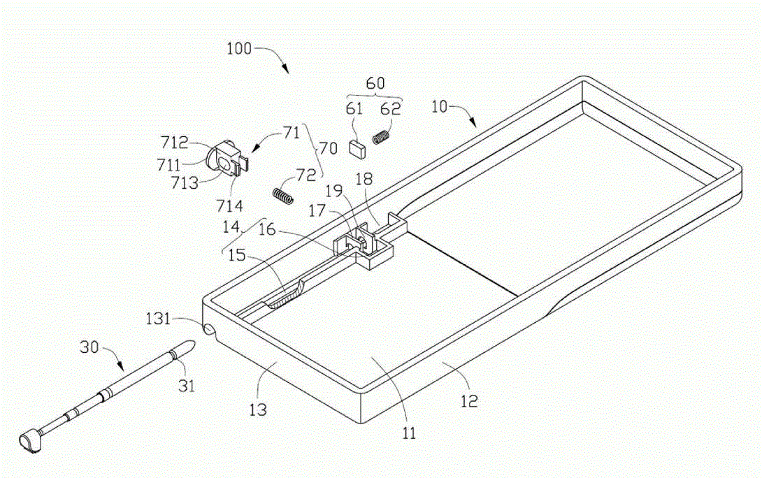
图1是本发明手写笔弹出机构的一较佳实施例的立体分解图。FIG. 1 is a three-dimensional exploded view of a preferred embodiment of the stylus ejection mechanism of the present invention.
图2是图1所示手写笔弹出机构的局部放大图。FIG. 2 is a partially enlarged view of the ejection mechanism of the stylus shown in FIG. 1 .
图3是图1所示手写笔弹出机构另一角度的立体示意图。FIG. 3 is a schematic perspective view of another angle of the stylus ejection mechanism shown in FIG. 1 .
图4是图1所示手写笔弹出机构的组装示意图。FIG. 4 is a schematic diagram of assembly of the stylus ejection mechanism shown in FIG. 1 .
图5是图4所示手写笔弹出机构沿V-V方向的剖视图,其中手写笔处于锁持状态。FIG. 5 is a cross-sectional view along the V-V direction of the ejecting mechanism of the stylus shown in FIG. 4 , where the stylus is in a locked state.
图6是图5所示手写笔弹出机构的运动状态示意图。FIG. 6 is a schematic diagram of the movement state of the ejection mechanism of the stylus shown in FIG. 5 .
具体实施方式Detailed ways
请参阅图1和图2,本发明的较佳实施例公开一种手写笔弹出机构100,其适用于移动电话等便携式电子装置。该手写笔弹出机构100包括一壳体10、一手写笔30、一弹性操作组件60和一弹性顶出组件70。Please refer to FIG. 1 and FIG. 2 , a preferred embodiment of the present invention discloses a
所述壳体10大致为长方体状,其包括一底壁11、二相对侧壁12、二相对端壁13和一安装部14。该二侧壁12与该二端壁13沿所述底壁11的一周侧边缘垂直延伸形成,且该二侧壁12相对两端均与该二端壁13相连。所述一侧壁12上开有一大致椭圆形的按钮孔121(参见图3)。所述一端壁13端部与该底壁11连接处开设一笔孔131,用于由此装设该手写笔30于壳体10内及由此取出手写笔30。The
该安装部14包括一装配槽15、一容置槽16和一设于装配槽15内的卡持部17。该装配槽15为一长方形,其设置于该壳体10的一角处并与该按钮孔121及该笔孔131相贯通。该装配槽15包括一槽底壁150、一槽侧壁151和一槽端壁152。该槽底壁150为该壳体10的底壁11的一部分,该槽底壁150上设有一与卡持部17相连通的笔槽155,用以容置该手写笔30。该槽侧壁151由底壁11上凸起形成,该槽侧壁151与设有按钮孔121的侧壁12相对;该槽侧壁151一端与设有笔孔131的端壁13相连,另一端与该槽端壁152相连。该槽端壁152由底壁11上凸起形成,该槽端壁152两端分别与该侧壁12及该槽端壁152相连,并与该笔孔131相对。The installation portion 14 includes an
所述容置槽16为一与按钮孔121贯通的矩形开口槽,其由该槽侧壁151与该按钮孔121相对的部分断开一缺口并向远离该按钮孔121方向延伸围成。该容置槽16包括一与按钮孔121相对的抵持壁161。The accommodating groove 16 is a rectangular open groove penetrating with the
所述卡持部17包括二相对的卡持壁171和二装设孔172。该二卡持壁171大致为“L”型板状,其由该按钮孔121两侧向该按钮孔121相对延伸并向容置槽16方向弯折形成。该二卡持壁171设有一卡持端173。该卡持端173与该抵持壁161相对并与槽侧壁151相连接,从而该二卡持壁171与该槽端壁152之间形成一第一容置空间18,用于容置所述弹性顶出组件60。该二卡持壁171与容置槽16之间形成一与按钮孔121贯通的第二容置空间19,用于容置并卡持该弹性操作组件70。该二装设孔172分别开设于该二卡持壁171上。该二装设孔172与该笔孔131相对并与该笔槽155相连通。The
该手写笔30上凹设有一沟槽31,该手写笔30安装于壳体10内。A
所述弹性顶出组件60用于弹出该手写笔30,其包括一矩形的滑块61和一螺旋状的弹簧62。该滑块61可在该第一容置空间18内滑动。该弹簧62夹设于槽端壁152与滑块61之间。The
请一并参阅图3,该弹性操作组件70包括一操作件71和一弹性件72。该操作件71包括一按压板711、一基体712、一滑槽713和二卡钩714。在本实施例中,该按压板711为一椭圆形板,可收容于该按钮孔121内。该基体712为一凸设于该按压板711一表面中部的长方形块体,可容置于该二卡持壁171之间。该滑槽713为一贯通该基体712的椭圆形的通孔,其与该装设孔172相对应。该滑槽713远离按压板711的一内壁中部凸设一凸棱715,用于与手写笔30的沟槽31卡持(如图5所示)。该二卡钩714间隔相背凸设于该基体712端部。该弹性件72为螺旋弹簧,一端固接于该二卡钩714之间的基体712上,另一端抵持于抵持壁161上。Please also refer to FIG. 3 , the
请参阅图4和图5,装配时,先将该弹性顶出组件60装配于该第一容置空间18内,该弹簧62处于压缩状态,其弹力使该滑块61抵于该卡持壁171上。然后,将该操作件71通过该按钮孔121装设于该第二容置空间19内,此时,该按压板711容置于该按钮孔121内,该基体712容置于该二该卡持壁171之间,二卡钩714分别卡持于该二卡持壁171的卡持端173,以避免该卡持件71从该壳体10上脱落。该弹性件72处于预压缩状态,夹持于基体712与抵持壁161间。最后,将手写笔30通过该笔孔131装配于笔槽155内,使该手写笔30穿过该装设孔172和滑槽713,手写笔30推动该滑块61压缩弹簧62,当该操作件71上的凸棱715卡持于该沟槽31内时,该手写笔30完全收容并固定于壳体10内。Please refer to Fig. 4 and Fig. 5, when assembling, first assemble the
请参阅图6,使用该手写笔30时,只需向壳体10方向按压操作件71的按压板711,该基体712压缩弹性件72并带动该滑槽713向抵持壁161滑动,此时,该手写笔30被该装设孔172阻挡,该凸棱715与该手写笔30的沟槽31之间的卡锁解除,该滑块61在该弹簧62的回复力推动下沿装配槽15滑动,从而将该手写笔30推出。Please refer to FIG. 6. When using the
所述手写笔弹出机构100通过该操作件71将手写笔固定于壳体10内,并通过按压该操作件71及与弹性顶出组件60的配合,使该手写笔30弹出。该手写笔弹出机构结构简单。The stylus
另外,本领域技术人员还可在本发明权利要求公开的范围和精神内做其它形式和细节上的各种修改、添加和替换。当然,这些依据本发明精神所做的各种修改、添加和替换等变化,都应包含在本发明所要求保护的范围之内。In addition, those skilled in the art can also make various modifications, additions and substitutions in other forms and details within the scope and spirit disclosed in the claims of the present invention. Certainly, the various modifications, additions, substitutions and other changes made according to the spirit of the present invention shall all be included within the scope of protection claimed by the present invention.
Claims (7)
Priority Applications (2)
| Application Number | Priority Date | Filing Date | Title |
|---|---|---|---|
| CN200910300966.6A CN101841581B (en) | 2009-03-19 | 2009-03-19 | Stylus pen ejecting mechanism |
| US12/568,794 US7796382B1 (en) | 2009-03-19 | 2009-09-29 | Stylus ejecting mechanism for portable electronic device |
Applications Claiming Priority (1)
| Application Number | Priority Date | Filing Date | Title |
|---|---|---|---|
| CN200910300966.6A CN101841581B (en) | 2009-03-19 | 2009-03-19 | Stylus pen ejecting mechanism |
Publications (2)
| Publication Number | Publication Date |
|---|---|
| CN101841581A true CN101841581A (en) | 2010-09-22 |
| CN101841581B CN101841581B (en) | 2014-02-12 |
Family
ID=42710986
Family Applications (1)
| Application Number | Title | Priority Date | Filing Date |
|---|---|---|---|
| CN200910300966.6A Expired - Fee Related CN101841581B (en) | 2009-03-19 | 2009-03-19 | Stylus pen ejecting mechanism |
Country Status (2)
| Country | Link |
|---|---|
| US (1) | US7796382B1 (en) |
| CN (1) | CN101841581B (en) |
Cited By (8)
| Publication number | Priority date | Publication date | Assignee | Title |
|---|---|---|---|---|
| CN102595839A (en) * | 2011-01-11 | 2012-07-18 | 和硕联合科技股份有限公司 | Electronic device for pop-up module and its application |
| CN103763417A (en) * | 2014-02-12 | 2014-04-30 | 陈璐瑶 | Energy-saving wrist mobile phone |
| CN103824716A (en) * | 2012-11-16 | 2014-05-28 | 杨秀铃 | Switch lighting device |
| CN106648169A (en) * | 2016-11-28 | 2017-05-10 | 上海传英信息技术有限公司 | Capacitive stylus device |
| CN108595034A (en) * | 2018-06-15 | 2018-09-28 | 汉王科技股份有限公司 | Handwriting ejecting structure, stylus and electronic equipment |
| CN111031428A (en) * | 2016-12-19 | 2020-04-17 | 华为技术有限公司 | Wearable equipment with bluetooth headset |
| CN113853076A (en) * | 2021-08-16 | 2021-12-28 | 深圳微步信息股份有限公司 | Touch pen assembly structure and electronic equipment |
| CN116578169A (en) * | 2023-05-16 | 2023-08-11 | 广东虹勤通讯技术有限公司 | Touch pen positioning device and electronic equipment |
Families Citing this family (12)
| Publication number | Priority date | Publication date | Assignee | Title |
|---|---|---|---|---|
| WO2007037758A1 (en) * | 2005-09-30 | 2007-04-05 | Olympus Technologies Singapore Pte Ltd | Stylus retention for an industrial portable electronic device |
| CN102196065A (en) * | 2010-03-15 | 2011-09-21 | 深圳富泰宏精密工业有限公司 | Handwriting pen fixing structure and portable electronic device with same |
| TWM406759U (en) * | 2010-12-01 | 2011-07-01 | Wistron Corp | Portable electronic device with a space for accommodating a stylus and a connector |
| TWI456374B (en) * | 2011-03-03 | 2014-10-11 | Acer Inc | Notebook |
| CN102858118B (en) * | 2011-06-30 | 2015-04-29 | 环旭电子股份有限公司 | Combination structure of pen-shaped object and casing |
| CN103002689A (en) * | 2011-09-19 | 2013-03-27 | 深圳富泰宏精密工业有限公司 | Stylus popup mechanism and portable electronic device applying same |
| TWI429373B (en) * | 2011-11-24 | 2014-03-01 | Wistron Corp | Holding structure and portable electronic apparatus therewith |
| USD749564S1 (en) * | 2014-01-29 | 2016-02-16 | Samsung Electronics Co., Ltd. | Portable electronic device |
| USD749565S1 (en) * | 2014-01-29 | 2016-02-16 | Samsung Electronics Co., Ltd. | Portable electronic device |
| KR101776262B1 (en) * | 2014-06-27 | 2017-09-11 | 삼성전자주식회사 | Foldable device |
| TWI664517B (en) * | 2017-03-16 | 2019-07-01 | 仁寶電腦工業股份有限公司 | Electronic assembly |
| EP4270146A4 (en) * | 2021-07-08 | 2024-08-07 | Samsung Electronics Co., Ltd. | ELECTRONIC DEVICE WITH PIN FASTENING DEVICE |
Family Cites Families (4)
| Publication number | Priority date | Publication date | Assignee | Title |
|---|---|---|---|---|
| US6664953B2 (en) * | 1998-08-06 | 2003-12-16 | Hewlett-Packard Development Company, L.P. | Method and receptacle for receiving and releasing a pen |
| US6129430A (en) * | 1999-06-03 | 2000-10-10 | Inventec Corp. | Stylus removal mechanism |
| TW471670U (en) * | 2000-07-20 | 2002-01-01 | High Tech Comp Corp | Ejection mechanism of touch pen |
| TWM268986U (en) * | 2004-12-10 | 2005-07-01 | Fih Co Ltd | Stylus elastic removal mechanism |
-
2009
- 2009-03-19 CN CN200910300966.6A patent/CN101841581B/en not_active Expired - Fee Related
- 2009-09-29 US US12/568,794 patent/US7796382B1/en not_active Expired - Fee Related
Cited By (10)
| Publication number | Priority date | Publication date | Assignee | Title |
|---|---|---|---|---|
| CN102595839A (en) * | 2011-01-11 | 2012-07-18 | 和硕联合科技股份有限公司 | Electronic device for pop-up module and its application |
| CN103824716A (en) * | 2012-11-16 | 2014-05-28 | 杨秀铃 | Switch lighting device |
| CN103824716B (en) * | 2012-11-16 | 2016-01-20 | 杨秀铃 | Switch lighting device |
| CN103763417A (en) * | 2014-02-12 | 2014-04-30 | 陈璐瑶 | Energy-saving wrist mobile phone |
| CN106648169A (en) * | 2016-11-28 | 2017-05-10 | 上海传英信息技术有限公司 | Capacitive stylus device |
| CN111031428A (en) * | 2016-12-19 | 2020-04-17 | 华为技术有限公司 | Wearable equipment with bluetooth headset |
| CN111031428B (en) * | 2016-12-19 | 2021-11-09 | 华为技术有限公司 | Wearable equipment with bluetooth headset |
| CN108595034A (en) * | 2018-06-15 | 2018-09-28 | 汉王科技股份有限公司 | Handwriting ejecting structure, stylus and electronic equipment |
| CN113853076A (en) * | 2021-08-16 | 2021-12-28 | 深圳微步信息股份有限公司 | Touch pen assembly structure and electronic equipment |
| CN116578169A (en) * | 2023-05-16 | 2023-08-11 | 广东虹勤通讯技术有限公司 | Touch pen positioning device and electronic equipment |
Also Published As
| Publication number | Publication date |
|---|---|
| US7796382B1 (en) | 2010-09-14 |
| CN101841581B (en) | 2014-02-12 |
| US20100238615A1 (en) | 2010-09-23 |
Similar Documents
| Publication | Publication Date | Title |
|---|---|---|
| CN101841581B (en) | Stylus pen ejecting mechanism | |
| US8363036B2 (en) | Stylus retaining mechanism for portable electronic device | |
| US7837484B2 (en) | Cover mechanism and electronic device using same | |
| US8453297B2 (en) | Electronic device and handle structure thereof | |
| US8154878B2 (en) | Chip card holder | |
| US8322760B2 (en) | Battery cover mechanism | |
| US8360485B2 (en) | Holding mechanism and electronic device using the same | |
| US20130309885A1 (en) | Holder for surface contact card for electronic device | |
| US8194055B2 (en) | Stylus retaining mechanism for portable electronic device | |
| TW201436387A (en) | Electronic device with latching mechanism | |
| CN108615992B (en) | Card seat assembly and electronic device | |
| US8251408B2 (en) | Battery cover latch mechanism and portable electronic device using same | |
| US8390601B2 (en) | Stylus retaining mechanism for portable electronic device | |
| CN101840245A (en) | Stylus pen ejecting mechanism | |
| US8390602B2 (en) | Stylus retaining mechanism for portable electronic device | |
| US8264845B2 (en) | Electronic device with cover ejection mechanism | |
| CN101500380A (en) | Cover-turning type electronic device casing | |
| CN108615991B (en) | Card seat assembly and electronic device | |
| US8369088B2 (en) | Electronic device | |
| US20100167114A1 (en) | Battery cover latch mechanism and portable electronic device using the same | |
| CN102595839B (en) | Electronic device for pop-up module and its application | |
| TWI439203B (en) | Stylus pop-up mechanism | |
| JP5389708B2 (en) | Input pen holding device and electronic device equipped with the same | |
| CN108540156A (en) | Deck component and electronic device | |
| CN108649359B (en) | Card insertion device and electronic equipment |
Legal Events
| Date | Code | Title | Description |
|---|---|---|---|
| C06 | Publication | ||
| PB01 | Publication | ||
| C10 | Entry into substantive examination | ||
| SE01 | Entry into force of request for substantive examination | ||
| C14 | Grant of patent or utility model | ||
| GR01 | Patent grant | ||
| CF01 | Termination of patent right due to non-payment of annual fee |
Granted publication date: 20140212 Termination date: 20150319 |
|
| EXPY | Termination of patent right or utility model |