CN101685269B - Exposure apparatus and device producing method - Google Patents
Exposure apparatus and device producing method Download PDFInfo
- Publication number
- CN101685269B CN101685269B CN2009102071284A CN200910207128A CN101685269B CN 101685269 B CN101685269 B CN 101685269B CN 2009102071284 A CN2009102071284 A CN 2009102071284A CN 200910207128 A CN200910207128 A CN 200910207128A CN 101685269 B CN101685269 B CN 101685269B
- Authority
- CN
- China
- Prior art keywords
- liquid
- substrate
- optical element
- recovery
- exposure
- Prior art date
- Legal status (The legal status is an assumption and is not a legal conclusion. Google has not performed a legal analysis and makes no representation as to the accuracy of the status listed.)
- Expired - Fee Related
Links
Images


Classifications
-
- G—PHYSICS
- G03—PHOTOGRAPHY; CINEMATOGRAPHY; ANALOGOUS TECHNIQUES USING WAVES OTHER THAN OPTICAL WAVES; ELECTROGRAPHY; HOLOGRAPHY
- G03F—PHOTOMECHANICAL PRODUCTION OF TEXTURED OR PATTERNED SURFACES, e.g. FOR PRINTING, FOR PROCESSING OF SEMICONDUCTOR DEVICES; MATERIALS THEREFOR; ORIGINALS THEREFOR; APPARATUS SPECIALLY ADAPTED THEREFOR
- G03F7/00—Photomechanical, e.g. photolithographic, production of textured or patterned surfaces, e.g. printing surfaces; Materials therefor, e.g. comprising photoresists; Apparatus specially adapted therefor
- G03F7/70—Microphotolithographic exposure; Apparatus therefor
- G03F7/70216—Mask projection systems
- G03F7/70341—Details of immersion lithography aspects, e.g. exposure media or control of immersion liquid supply
-
- G—PHYSICS
- G03—PHOTOGRAPHY; CINEMATOGRAPHY; ANALOGOUS TECHNIQUES USING WAVES OTHER THAN OPTICAL WAVES; ELECTROGRAPHY; HOLOGRAPHY
- G03F—PHOTOMECHANICAL PRODUCTION OF TEXTURED OR PATTERNED SURFACES, e.g. FOR PRINTING, FOR PROCESSING OF SEMICONDUCTOR DEVICES; MATERIALS THEREFOR; ORIGINALS THEREFOR; APPARATUS SPECIALLY ADAPTED THEREFOR
- G03F7/00—Photomechanical, e.g. photolithographic, production of textured or patterned surfaces, e.g. printing surfaces; Materials therefor, e.g. comprising photoresists; Apparatus specially adapted therefor
- G03F7/70—Microphotolithographic exposure; Apparatus therefor
- G03F7/70216—Mask projection systems
- G03F7/70225—Optical aspects of catadioptric systems, i.e. comprising reflective and refractive elements
-
- G—PHYSICS
- G03—PHOTOGRAPHY; CINEMATOGRAPHY; ANALOGOUS TECHNIQUES USING WAVES OTHER THAN OPTICAL WAVES; ELECTROGRAPHY; HOLOGRAPHY
- G03F—PHOTOMECHANICAL PRODUCTION OF TEXTURED OR PATTERNED SURFACES, e.g. FOR PRINTING, FOR PROCESSING OF SEMICONDUCTOR DEVICES; MATERIALS THEREFOR; ORIGINALS THEREFOR; APPARATUS SPECIALLY ADAPTED THEREFOR
- G03F7/00—Photomechanical, e.g. photolithographic, production of textured or patterned surfaces, e.g. printing surfaces; Materials therefor, e.g. comprising photoresists; Apparatus specially adapted therefor
- G03F7/70—Microphotolithographic exposure; Apparatus therefor
- G03F7/70216—Mask projection systems
- G03F7/70316—Details of optical elements, e.g. of Bragg reflectors, extreme ultraviolet [EUV] multilayer or bilayer mirrors or diffractive optical elements
-
- G—PHYSICS
- G03—PHOTOGRAPHY; CINEMATOGRAPHY; ANALOGOUS TECHNIQUES USING WAVES OTHER THAN OPTICAL WAVES; ELECTROGRAPHY; HOLOGRAPHY
- G03F—PHOTOMECHANICAL PRODUCTION OF TEXTURED OR PATTERNED SURFACES, e.g. FOR PRINTING, FOR PROCESSING OF SEMICONDUCTOR DEVICES; MATERIALS THEREFOR; ORIGINALS THEREFOR; APPARATUS SPECIALLY ADAPTED THEREFOR
- G03F7/00—Photomechanical, e.g. photolithographic, production of textured or patterned surfaces, e.g. printing surfaces; Materials therefor, e.g. comprising photoresists; Apparatus specially adapted therefor
- G03F7/70—Microphotolithographic exposure; Apparatus therefor
- G03F7/708—Construction of apparatus, e.g. environment aspects, hygiene aspects or materials
- G03F7/70808—Construction details, e.g. housing, load-lock, seals or windows for passing light in or out of apparatus
- G03F7/70825—Mounting of individual elements, e.g. mounts, holders or supports
-
- G—PHYSICS
- G03—PHOTOGRAPHY; CINEMATOGRAPHY; ANALOGOUS TECHNIQUES USING WAVES OTHER THAN OPTICAL WAVES; ELECTROGRAPHY; HOLOGRAPHY
- G03F—PHOTOMECHANICAL PRODUCTION OF TEXTURED OR PATTERNED SURFACES, e.g. FOR PRINTING, FOR PROCESSING OF SEMICONDUCTOR DEVICES; MATERIALS THEREFOR; ORIGINALS THEREFOR; APPARATUS SPECIALLY ADAPTED THEREFOR
- G03F7/00—Photomechanical, e.g. photolithographic, production of textured or patterned surfaces, e.g. printing surfaces; Materials therefor, e.g. comprising photoresists; Apparatus specially adapted therefor
- G03F7/70—Microphotolithographic exposure; Apparatus therefor
- G03F7/708—Construction of apparatus, e.g. environment aspects, hygiene aspects or materials
- G03F7/70908—Hygiene, e.g. preventing apparatus pollution, mitigating effect of pollution or removing pollutants from apparatus
- G03F7/70916—Pollution mitigation, i.e. mitigating effect of contamination or debris, e.g. foil traps
-
- G—PHYSICS
- G03—PHOTOGRAPHY; CINEMATOGRAPHY; ANALOGOUS TECHNIQUES USING WAVES OTHER THAN OPTICAL WAVES; ELECTROGRAPHY; HOLOGRAPHY
- G03F—PHOTOMECHANICAL PRODUCTION OF TEXTURED OR PATTERNED SURFACES, e.g. FOR PRINTING, FOR PROCESSING OF SEMICONDUCTOR DEVICES; MATERIALS THEREFOR; ORIGINALS THEREFOR; APPARATUS SPECIALLY ADAPTED THEREFOR
- G03F7/00—Photomechanical, e.g. photolithographic, production of textured or patterned surfaces, e.g. printing surfaces; Materials therefor, e.g. comprising photoresists; Apparatus specially adapted therefor
- G03F7/70—Microphotolithographic exposure; Apparatus therefor
- G03F7/708—Construction of apparatus, e.g. environment aspects, hygiene aspects or materials
- G03F7/7095—Materials, e.g. materials for housing, stage or other support having particular properties, e.g. weight, strength, conductivity, thermal expansion coefficient
- G03F7/70958—Optical materials or coatings, e.g. with particular transmittance, reflectance or anti-reflection properties
Landscapes
- Physics & Mathematics (AREA)
- General Physics & Mathematics (AREA)
- Health & Medical Sciences (AREA)
- Epidemiology (AREA)
- Public Health (AREA)
- Engineering & Computer Science (AREA)
- Atmospheric Sciences (AREA)
- Life Sciences & Earth Sciences (AREA)
- Environmental & Geological Engineering (AREA)
- Exposure Of Semiconductors, Excluding Electron Or Ion Beam Exposure (AREA)
- Exposure And Positioning Against Photoresist Photosensitive Materials (AREA)
- Condensed Matter Physics & Semiconductors (AREA)
- Manufacturing & Machinery (AREA)
- Computer Hardware Design (AREA)
- Microelectronics & Electronic Packaging (AREA)
- Power Engineering (AREA)
- Optics & Photonics (AREA)
Abstract
曝光装置(EX)具有投影光学系统(PL)。投影光学系统(PL),具有最接近其像面的第1光学元件(LS1)、及次于第1光学元件(LS1)接近像面的第2光学元件(LS2)。第1光学元件(LS1),具有:配置成与基板(P)表面对向的下面(T1)、及配置成与第2光学元件(LS2)对向的上面(T2)。以第2液体(LQ2)充满于第1光学元件(LS1)的上面(T2)与第2光学元件(LS2)之间,以在上面(T2)中、在包含曝光用光(EL)通过的区域(AR’)的区域形成液浸区域,通过第1光学元件(LS1)的下面(T1)侧的第1液体(LQ1)、与上面(T2)侧的第2液体(LQ2)将曝光用光(EL)照射于基板(P)上,由此使基板(P)曝光。如此能防止因光学元件污染使曝光精度劣化,并抑制液浸区域的巨大化。
The exposure device (EX) has a projection optical system (PL). The projection optical system (PL) has a first optical element (LS1) closest to the image plane, and a second optical element (LS2) next to the first optical element (LS1) and closer to the image plane. The first optical element (LS1) has a lower surface (T1) arranged to face the surface of the substrate (P), and an upper surface (T2) arranged to face the second optical element (LS2). The second liquid (LQ2) is filled between the upper surface (T2) of the first optical element (LS1) and the second optical element (LS2), so that in the upper surface (T2), including exposure light (EL) passing through The region of region (AR') forms a liquid immersion region, through which the first liquid (LQ1) on the lower side (T1) side of the first optical element (LS1) and the second liquid (LQ2) on the upper side (T2) side will pass through the first optical element (LS1) for exposure. Light (EL) is irradiated on the substrate (P), thereby exposing the substrate (P). This prevents exposure accuracy from deteriorating due to contamination of optical elements and suppresses enlargement of the liquid immersion area.
Description
本发明是“曝光装置、曝光方法、以及元件制造方法”的分案申请,原申请日为:2005年6月8日;原申请号为:200580023160.7(国际申请号为:PCT/JP2005/010484)。The present invention is a divisional application of "exposure device, exposure method, and component manufacturing method". The original application date is: June 8, 2005; the original application number is: 200580023160.7 (the international application number is: PCT/JP2005/010484) .
技术领域technical field
本发明是关于通过液体使基板曝光的曝光装置、曝光方法、以及元件制造方法。The present invention relates to an exposure apparatus, an exposure method, and a device manufacturing method for exposing a substrate with a liquid.
背景技术Background technique
半导体元件或液晶显示元件,是由将形成于掩膜上的图案转印于感光性基板上、即所谓的光刻方法来制造。此光刻步骤所使用的曝光装置,具有支撑掩膜的掩膜载台与支撑基板的基板载台,使掩膜载台与基板载台一边逐次移动一边通过投影光学系统将掩膜的图案转印于基板。近年来,为对应元件图案的更高集成化,而期待投影光学系统具有更高分辨率。投影光学系统的分辨率,是所使用的曝光波长越短、或投影光学系统的数值孔径越大则会越提高。因此,曝光装置所使用的曝光波长逐年变短,投影光学系统的数值孔径则逐渐增大。又,目前主流的曝光波长虽为KrF准分子雷射光的248nm,但波长更短的ArF准分子雷射光的193nm也逐渐实用化。又,进行曝光时,焦深(DOF)也与分辨率同样重要。分辨率R及焦深δ分别以下式表示。A semiconductor element or a liquid crystal display element is manufactured by a so-called photolithography method that transfers a pattern formed on a mask onto a photosensitive substrate. The exposure apparatus used in this photolithography step has a mask stage that supports the mask and a substrate stage that supports the substrate. The mask stage and the substrate stage are moved sequentially while the pattern of the mask is transferred to the surface through the projection optical system. printed on the substrate. In recent years, projection optical systems are expected to have higher resolution in order to cope with higher integration of device patterns. The resolution of the projection optical system increases as the exposure wavelength used becomes shorter, or as the numerical aperture of the projection optical system increases. Therefore, the exposure wavelength used by the exposure device is shortened year by year, and the numerical aperture of the projection optical system is gradually increased. Also, although the current mainstream exposure wavelength is 248nm of KrF excimer laser light, the shorter wavelength of ArF excimer laser light of 193nm is gradually being put into practical use. Also, when performing exposure, the depth of focus (DOF) is also as important as the resolution. The resolution R and the depth of focus δ are represented by the following equations, respectively.
R=k1·λ/NA…(1)R=k 1 ·λ/NA...(1)
δ=±k2·λ/NA2…(2)δ=±k 2 ·λ/NA 2 ...(2)
此处,λ为曝光波长,NA为投影光学系统的数值孔径,k1、k2为处理系数。从(1)式、(2)式可知,为了提高分辨率R,而缩短曝光波长λ、增大数值孔径NA时,即会使焦深δ变窄。Here, λ is the exposure wavelength, NA is the numerical aperture of the projection optical system, and k 1 and k 2 are processing coefficients. From formula (1) and formula (2), it can be seen that in order to increase the resolution R, shortening the exposure wavelength λ and increasing the numerical aperture NA will narrow the depth of focus δ.
若焦深δ变得过窄,即难以使基板表面与投影光学系统的像面一致,有进行曝光动作时焦点裕度不足之虞。因此,作为实质上缩短曝光波长且扩大焦深的方法,例如已有提出一种国际公开第99/49504号公报所揭示的液浸法。此液浸法,是以水或有机溶媒等液体充满投影光学系统下面与基板表面间来形成液浸区域,利用液体中的曝光用光的实质波长为在空气中的1/n倍(n为液体折射率,通常为1.2~1.6左右)这点来提高分辨率,且能将焦深放大至n倍。If the depth of focus δ is too narrow, it is difficult to align the substrate surface with the image plane of the projection optical system, and there is a possibility that the focus margin will be insufficient during the exposure operation. Therefore, as a method of substantially shortening the exposure wavelength and increasing the depth of focus, for example, a liquid immersion method disclosed in International Publication No. 99/49504 has been proposed. In this liquid immersion method, liquids such as water or organic solvents are filled between the bottom of the projection optical system and the surface of the substrate to form a liquid immersion area, and the substantial wavelength of the exposure light in the liquid is 1/n times that in air (n is The refractive index of the liquid is usually about 1.2 to 1.6) to improve the resolution and to enlarge the depth of focus to n times.
此外,在上述国际公开第99/49504号公报所揭示的液浸曝光装置中,形成于基板上的液浸区域的液体,是接触于构成投影光学系统的复数个元件(光学元件)中配置于最接近像面的光学元件。此时,当例如基板上所产生的杂质等混入液浸区域的液体中、而污染液浸区域的液体时,即有可能因该受污染的液浸区域的液体,使前述配置于最接近像面的光学元件受到污染。当光学元件受到污染时,即可能产生该光学元件的光透射率降低、或光透射率分布不良等状况,导致通过投影光学系统的曝光精度及测量精度劣化。In addition, in the liquid immersion exposure apparatus disclosed in the above-mentioned International Publication No. 99/49504, the liquid formed in the liquid immersion region on the substrate is placed in contact with a plurality of elements (optical elements) constituting the projection optical system. The optical element closest to the image plane. At this time, when, for example, impurities generated on the substrate are mixed into the liquid in the liquid immersion area to contaminate the liquid in the liquid immersion area, the liquid in the contaminated liquid immersion area may cause the aforementioned arrangement to be placed closest to the image. Surface optics are contaminated. When the optical element is polluted, the light transmittance of the optical element may decrease, or the light transmittance distribution may be poor, resulting in deterioration of exposure accuracy and measurement accuracy through the projection optical system.
又,上述国际公开第99/49504号公报中,虽揭示了一种一边使掩膜与基板同步移动于扫描方向、一边将掩膜所形成的图案曝光于基板的扫描型曝光装置,但此种扫描型曝光装置,为了要提高元件的生产性等而被要求扫描速度更高速。然而,在使扫描速度更高速时,即有可能难以将液浸区域维持于所欲的大小。In addition, the above-mentioned International Publication No. 99/49504 discloses a scanning exposure device that exposes a pattern formed by the mask on the substrate while moving the mask and the substrate synchronously in the scanning direction. Scanning exposure apparatuses are required to have higher scanning speeds in order to improve device productivity and the like. However, when the scanning speed is increased, it may be difficult to maintain the desired size of the liquid immersion area.
发明内容Contents of the invention
本发明有鉴于上述情形,其目的是提供一种可防止因元件(光学元件)的污染而使其曝光精度及测量精度劣化的曝光装置、以及使用该曝光装置的元件制造方法。又,本发明的目的是提供一种可将液浸区域维持于所欲状态的曝光装置、曝光方法、以及使用该曝光装置的元件制造方法。The present invention is made in view of the above circumstances, and an object of the present invention is to provide an exposure apparatus capable of preventing degradation of exposure accuracy and measurement accuracy due to contamination of elements (optical elements), and an element manufacturing method using the exposure apparatus. Another object of the present invention is to provide an exposure device capable of maintaining a liquid immersion region in a desired state, an exposure method, and a device manufacturing method using the exposure device.
本发明的目的是这样实现的,一种曝光装置,是通过第1液体将曝光用光照射于基板上以使基板曝光,具有:The purpose of the present invention is achieved in this way, an exposure device is to irradiate the exposure light on the substrate through the first liquid to expose the substrate, and has:
投影光学系统,具有多个元件,其包含最接近像面的第1元件、以及次于该第1元件接近该像面的第2元件;A projection optical system having a plurality of elements including a first element closest to the image plane, and a second element next to the first element closer to the image plane;
第1液浸机构,是将该第1液体供应至该第1元件与该基板之间;a first liquid immersion mechanism for supplying the first liquid between the first element and the substrate;
第2液浸机构,是将第2液体供应至该第1元件与该第2元件之间;a second liquid immersion mechanism for supplying a second liquid between the first element and the second element;
该第1元件,具有配置成与该基板表面对向、使曝光用光通过的第1面;以及配置成与该第2元件对向、使曝光用光通过的第2面;The first element has a first surface arranged to face the substrate surface and allow exposure light to pass through it; and a second surface arranged to face the second element and allow exposure light to pass therethrough;
该第1液浸机构,具有使该曝光用光通过的开口、以及于该开口周围配置成与该基板表面对向的平坦液体接触面;The first liquid immersion mechanism has an opening through which the exposure light passes, and a flat liquid contact surface disposed around the opening so as to face the surface of the substrate;
该第1液浸机构,具有用以将该第1液体供应至该第1元件与该基板之间的空间的供应口、以及从该基板上方回收该第1液体的回收口;The first liquid immersion mechanism has a supply port for supplying the first liquid to the space between the first element and the substrate, and a recovery port for recovering the first liquid from above the substrate;
该第1液浸机构的该回收口配置成包围该液体接触面;The recovery port of the first liquid immersion mechanism is configured to surround the liquid contact surface;
于该第1液浸机构的该回收口配置多孔构件;disposing a porous member at the recovery port of the first liquid immersion mechanism;
该第2液浸机构,具有供应该第2液体的供应口与回收该第2液体的回收口;The second liquid immersion mechanism has a supply port for supplying the second liquid and a recovery port for recovering the second liquid;
使曝光用光通过在该第1元件的第1面与该基板间的该第1液体、以及在该第1元件的第2面与该第2元件间的该第2液体而照射于该基板上,以使该基板曝光。irradiating the substrate with exposure light through the first liquid between the first surface of the first element and the substrate, and the second liquid between the second surface of the first element and the second element on to expose the substrate.
为解决上述问题,本发明采用了对应实施形态所示的图1~图16的下述构成。不过,附加于各要素的包含括号的符号仅是该要素的例示,而并非限定各要素。In order to solve the above-mentioned problems, the present invention adopts the following configuration corresponding to FIGS. 1 to 16 shown in the embodiment. However, the symbols in parentheses attached to each element are merely illustrations of the element, and do not limit each element.
根据本发明的第1方面,提供一种曝光装置,是通过液体(LQ1)将曝光用光(EL)照射于基板(P)上来使基板(P)曝光,其特征在于,具备:投影光学系统(PL),具有复数个元件(LS1~LS7),其包含最接近像面的第1元件(LS1)、以及次于第1元件(LS1)接近该像面的第2元件(LS2);第1元件(LS1),具有配置成与基板(P)表面对向、使曝光用光(EL)通过的第1面(T1);以及配置成与第2元件(LS2)对向、使曝光用光(EL)通过的第2面(T2);第1元件(LS1)及第2元件(LS2),是相对投影光学系统(PL)的光轴(AX)被支撑成大致静止的状态,将液体充满于第1元件(LS1)的第2面(T1)与第2元件(LS2)之间,以在第1元件(LS1)的第2面(T2)中,仅使包含曝光用光(EL)通过的区域(AR’)的部分区域成为液浸区域(LR2),再通过第1元件(LS1)的第1面(T1)侧的第1液体(LQ1)、与第2面(T2)侧的第2液体(LQ2)将曝光用光(EL)照射于基板(P)上,以使基板(P)曝光。According to the first aspect of the present invention, there is provided an exposure apparatus for exposing the substrate (P) by irradiating exposure light (EL) on the substrate (P) through a liquid (LQ1), characterized in that it includes: a projection optical system (PL) has a plurality of elements (LS1-LS7), which includes the first element (LS1) closest to the image plane, and the second element (LS2) next to the first element (LS1) close to the image plane; 1 element (LS1) having a first surface (T1) arranged to face the surface of the substrate (P) for passing exposure light (EL); and arranged to face the second element (LS2) for exposure The second surface (T2) through which the light (EL) passes; the first element (LS1) and the second element (LS2) are supported in a substantially stationary state relative to the optical axis (AX) of the projection optical system (PL), and the The liquid is filled between the second surface (T1) of the first element (LS1) and the second element (LS2), so that in the second surface (T2) of the first element (LS1), only the exposure light ( Part of the region (AR') through which EL) passes becomes the liquid immersion region (LR2), and then passes through the first liquid (LQ1) on the first surface (T1) side of the first element (LS1) and the second surface (T2 ) side of the second liquid (LQ2) irradiates exposure light (EL) onto the substrate (P) to expose the substrate (P).
根据本发明,由第1液体来充满第1元件的第1面与基板之间、且以第2液体来充满第1元件的第2面与第2元件之间,而能在确保投影光学系统PL较大的像侧的数值孔径的状态下,使基板良好地曝光。又,当第1面侧的第1液体与基板接触时,虽污染第1元件的第1面侧的可能性高,但由于以液体充满各第1元件的第1面侧及第2面侧,因此能构成为可容易交换的第1元件。因此,可仅将该受污染的第1元件交换成干净的元件,而能通过具备该干净的第1元件的投影光学系统与液体,良好地进行曝光及测量。又,第2液体,由于仅于第1元件的第2面上的部分区域(包含曝光用光通过的区域)局部性地形成液浸区域,因此可防止第2液体从第1元件的第2面周围漏出。因此,能防止因漏出的第2液体导致第1元件周边机械零件等劣化。又,由在第1元件的第2面上局部性地形成第2液体的液浸区域,而能防止液体渗入例如支撑第1元件的支撑部,而可防止该支撑部劣化。又,由于第2液体是于第2面上局部性地形成液浸区域,因此不会接触于例如支撑元件的支撑部等。由此,能防止从支撑部等产生的杂质混入形成液浸区域的第2液体等不良状况。因此,能在维持第2液体的洁净度的状态下,良好地进行曝光处理及测量处理。According to the present invention, the space between the first surface of the first element and the substrate is filled with the first liquid, and the space between the second surface of the first element and the second element is filled with the second liquid, so that the projection optical system can be ensured. In the state of the numerical aperture on the image side where the PL is large, the substrate is well exposed. Again, when the first liquid on the first surface side is in contact with the substrate, although the possibility of contaminating the first surface side of the first element is high, since the first surface side and the second surface side of each first element are filled with liquid , so it can be configured as an easily replaceable first element. Therefore, only the contaminated first element can be replaced with a clean element, and exposure and measurement can be satisfactorily performed with the projection optical system and the liquid provided with the clean first element. Moreover, the second liquid locally forms a liquid immersion region only on the partial area (including the area through which the exposure light passes) on the second surface of the first element, so the second liquid can be prevented from flowing from the second surface of the first element. Leaks around the face. Therefore, it is possible to prevent deterioration of mechanical parts around the first element due to the leaked second liquid. In addition, by locally forming the liquid immersion region of the second liquid on the second surface of the first element, it is possible to prevent the liquid from penetrating into, for example, the supporting portion supporting the first element, thereby preventing the supporting portion from deteriorating. In addition, since the second liquid locally forms a liquid immersion region on the second surface, it does not come into contact with, for example, the supporting portion of the supporting member. Accordingly, it is possible to prevent problems such as contamination of impurities generated from the support portion and the like into the second liquid forming the liquid immersion region. Therefore, exposure processing and measurement processing can be satisfactorily performed while maintaining the cleanliness of the second liquid.
此外,本发明的第1元件,也可是无折射力的透明构件(例如平行平面板),例如,即使配置于最接近像面的透明构件完全无助于投影光学系统的成像性能时,也可将该透明构件视为第1元件。又,虽本发明的第1元件及第2元件,是相对投影光学系统的光轴(曝光用光)被支撑成大致静止的状态,但第1元件与第2元件的至少其中一方,在为了调整其位置或姿势而被支撑成可进行微幅移动的情形下,也可视为「被支撑成大致静止的状态」。In addition, the first element of the present invention may also be a transparent member without refractive power (such as a parallel plane plate). For example, even if the transparent member disposed closest to the image plane does not contribute to the imaging performance of the projection optical system at all, This transparent member is regarded as a first element. Also, although the first element and the second element of the present invention are supported in a substantially stationary state with respect to the optical axis (exposure light) of the projection optical system, at least one of the first element and the second element is used for When it is supported to move slightly by adjusting its position or posture, it can also be regarded as "supported in a substantially stationary state".
根据本发明的第2方面,提供一种曝光装置(EX),是通过液体(LQ1)将曝光用光(EL)照射于基板(P)上来使基板(P)曝光,其特征在于,具备:投影光学系统(PL),具有复数个元件(LS1~LS7),其包含最接近像面的第1元件(LS1)、以及次于第1元件(LS1)接近该像面的第2元件(LS2);第1元件(LS1),具有配置成与基板(P)表面对向、使曝光用光(EL)通过的第1面(T1);以及配置成与第2元件(LS2)对向、使曝光用光(EL)通过的第2面(T2);与第1元件(LS1)对向的第2元件(LS2)的面(T3)外径(D3),是小于第1元件(LS1)的第2面(T2)的外径(D2);第1元件(LS1)及第2元件(LS2),是相对投影光学系统(PL)的光轴(AX)被支撑成大致静止的状态;通过第1元件(LS1)的第1面(T1)侧的第1液体(LQ1)、与第2面(T2)侧的第2液体(LQ2)将曝光用光(EL)照射于基板(P)上,以使基板(P)曝光。According to a second aspect of the present invention, an exposure device (EX) is provided, which exposes the substrate (P) by irradiating exposure light (EL) on the substrate (P) through a liquid (LQ1), characterized in that it has: The projection optical system (PL) has a plurality of elements (LS1~LS7), which include the first element (LS1) closest to the image plane, and the second element (LS2) next to the first element (LS1) close to the image plane ); a first element (LS1) having a first surface (T1) configured to face the surface of the substrate (P) through which exposure light (EL) passes; and disposed to face the second element (LS2), The second surface (T2) through which the exposure light (EL) passes; the outer diameter (D3) of the surface (T3) of the second element (LS2) facing the first element (LS1) is smaller than that of the first element (LS1) The outer diameter (D2) of the second surface (T2) of ); the first element (LS1) and the second element (LS2) are supported in a substantially stationary state relative to the optical axis (AX) of the projection optical system (PL) ; Exposure light (EL) is irradiated to the substrate ( P) to expose the substrate (P).
根据本发明,由于与第1元件对向的第2元件的对向面外径(D3),小于第1元件的第2面的外径(D2),因此能以第2液体覆盖该对向面,且能在第1元件的第2面上局部性地形成对应第2元件的面大小的液浸区域。因此,能防止第2液体从第1元件的第2面周围漏出,而防止因漏出的第2液体使第1元件周边机械构件等劣化。又,由于第2液体是于第2面上局部性地形成液浸区域,因此不会接触于例如支撑元件的支撑部等。由此,能防止从支撑部等产生的杂质混入形成液浸区域的第2液体等不良状况。因此,能维持第2液体的洁净度。又,通过于第2面上局部形成液浸区域的第2液体、以及于第1面侧形成液浸区域的第1液体,将曝光用光照射于基板上,由此能在确保投影光学系统PL较大的像侧的数值孔径的状态下,使基板良好地曝光。又,由于以液体充满各第1元件的第1面侧及第2面侧,因此能构成为可容易交换的第1元件。因此,可仅将受污染的第1元件交换成干净的元件,而能通过具备该干净的第1元件的投影光学系统与液体良好地进行曝光及测量。According to the present invention, since the outer diameter (D3) of the opposing surface of the second element facing the first element is smaller than the outer diameter (D2) of the second surface of the first element, the opposing surface can be covered with the second liquid. surface, and a liquid immersion region corresponding to the surface size of the second element can be locally formed on the second surface of the first element. Therefore, it is possible to prevent the second liquid from leaking around the second surface of the first element, and to prevent deterioration of mechanical components around the first element due to the leaked second liquid. In addition, since the second liquid locally forms a liquid immersion region on the second surface, it does not come into contact with, for example, the supporting portion of the supporting member. Accordingly, it is possible to prevent problems such as contamination of impurities generated from the support portion and the like into the second liquid forming the liquid immersion region. Therefore, the cleanliness of the second liquid can be maintained. In addition, the substrate is irradiated with exposure light by the second liquid that partially forms the liquid immersion region on the second surface and the first liquid that forms the liquid immersion region on the first surface side, thereby ensuring the accuracy of the projection optical system. In the state of the numerical aperture on the image side where the PL is large, the substrate is well exposed. Moreover, since the first surface side and the second surface side of each first element are filled with liquid, it can be configured as an easily replaceable first element. Therefore, only the contaminated first element can be replaced with a clean element, and exposure and measurement can be performed satisfactorily with the projection optical system including the clean first element and the liquid.
此外,本发明的第1元件,也可是无折射力的透明构件(例如平行平面板),例如,即使配置于最接近像面的透明构件完全无助于投影光学系统的成像性能时,也可将该透明构件当作第1元件而视为投影光学系统的一部分。又,虽本发明的第1元件及第2元件,是相对投影光学系统的光轴(曝光用光)被支撑成大致静止的状态,但第1元件与第2元件的至少其中一方,在为了调整其位置或姿势而被支撑成可进行微幅移动的情形下,也可视为「被支撑成大致静止的状态」。In addition, the first element of the present invention may also be a transparent member without refractive power (such as a parallel plane plate). For example, even if the transparent member disposed closest to the image plane does not contribute to the imaging performance of the projection optical system at all, This transparent member is regarded as a part of the projection optical system as the first element. Also, although the first element and the second element of the present invention are supported in a substantially stationary state with respect to the optical axis (exposure light) of the projection optical system, at least one of the first element and the second element is used for When it is supported to move slightly by adjusting its position or posture, it can also be regarded as "supported in a substantially stationary state".
根据本发明的第3方面,提供一种曝光装置(EX),是通过第1液体(LQ1)将曝光用光(EL)照射于基板(P)上来使基板(P)曝光,其特征在于,具备:投影光学系统(PL),具有包含复数个元件(LS1~LS7)且最接近像面的第1元件(LS1)、以及次于第1元件(LS1)接近该像面的第2元件(LS2);以及第1液浸机构(11)等,用以供应第1液体(LQ1);第1元件(LS1),具有配置成与基板(P)表面对向、使曝光用光(EL)通过的第1面(T1);以及配置成与第2元件(LS2)对向、与第1面(T1)大致平行的第2面(T2);第1元件(LS1)的第2面(T2)外径(D2),是大于第1元件(LS1)的第1面(T1)的外径(D1);通过第1元件(LS1)与基板(P)间的第1液体(LQ1)将曝光用光(EL)照射于基板(P)上,以使基板(P)曝光。According to a third aspect of the present invention, there is provided an exposure apparatus (EX) for exposing a substrate (P) by irradiating exposure light (EL) on the substrate (P) through a first liquid (LQ1), characterized in that, Equipped with: a projection optical system (PL) including a first element (LS1) closest to the image plane including a plurality of elements (LS1-LS7), and a second element (LS1) next to the first element (LS1) close to the image plane LS2); and the first liquid immersion mechanism (11), etc., used to supply the first liquid (LQ1); the first element (LS1), has a configuration to face the surface of the substrate (P) and use the exposure light (EL) The first surface (T1) passing through; and the second surface (T2) arranged to face the second element (LS2) and approximately parallel to the first surface (T1); the second surface (T2) of the first element (LS1) ( T2) The outer diameter (D2) is larger than the outer diameter (D1) of the first surface (T1) of the first element (LS1); the first liquid (LQ1) passing between the first element (LS1) and the substrate (P) The substrate (P) is irradiated with exposure light (EL) to expose the substrate (P).
根据本发明,由于将第1元件的第2面外径作成大于第1面的外径,因此以支撑部支撑第1元件时,可将该支撑第1元件的支撑部,设于从第1元件的光轴离开的位置(第2面端部)。由此,能防止配置于第1元件周边的构件或机器等与支撑部彼此干涉,而能提升前述构件或机器等的配置自由度及设计自由度。又,由于第1元件的第1面外径远小于第2面,因此能缩小由第1液浸机构在第1面与基板间形成的液浸区域大小。According to the present invention, since the outer diameter of the second surface of the first element is made larger than the outer diameter of the first surface, when the first element is supported by the supporting part, the supporting part for supporting the first element can be set on the first surface from the first surface. The position where the optical axis of the element departs (the end of the second surface). Thereby, it is possible to prevent the components, equipment, etc. arranged around the first element from interfering with the supporting portion, and to improve the degree of freedom in arrangement and design of the components, equipment, etc. described above. Moreover, since the outer diameter of the first surface of the first element is much smaller than that of the second surface, the size of the liquid immersion region formed between the first surface and the substrate by the first liquid immersion mechanism can be reduced.
此外,本发明的第1元件,也可是无折射力的透明构件(例如平行平面板),例如,即使配置于最接近像面的透明构件完全无助于投影光学系统的成像性能时,也可将该透明构件当作第1元件而视为投影光学系统的一部分。In addition, the first element of the present invention may also be a transparent member without refractive power (such as a parallel plane plate). For example, even if the transparent member disposed closest to the image plane does not contribute to the imaging performance of the projection optical system at all, This transparent member is regarded as a part of the projection optical system as the first element.
根据本发明的第4方面,提供一种曝光装置(EX),是通过第1液体(LQ1)将曝光用光(EL)照射于基板(P)上来使基板(P)曝光,其特征在于,具备:第1液浸机构(11)等,将第1液体供应至基板上;以及投影光学系统(PL),具有复数个元件(LS1~LS7),其包含最接近像面的第1元件(LS1)、以及次于第1元件(LS1)接近该像面的第2元件(LS2);第1元件(LS1),是配置成第1面(T1)与基板(P)表面对向且第2面(T2)与第2元件(LS2)对向;于投影光学系统(PL)的光轴(AX)上,第1元件(LS1)的第1面(T1)与第2面(T2)的距离(H1)为大于15mm;将曝光用光(EL)通过第1元件(LS1)的第1面(T1)侧的第1液体(LQ1)照射于基板(P)上,以使基板(P)曝光。According to a fourth aspect of the present invention, there is provided an exposure apparatus (EX) for exposing a substrate (P) by irradiating exposure light (EL) on the substrate (P) through a first liquid (LQ1), characterized in that, Equipped with: a first liquid immersion mechanism (11), etc., which supply the first liquid onto the substrate; and a projection optical system (PL), which has a plurality of elements (LS1-LS7) including the first element closest to the image plane ( LS1), and the second element (LS2) next to the first element (LS1) close to the image plane; the first element (LS1) is arranged so that the first surface (T1) faces the surface of the substrate (P) and the second The 2nd surface (T2) is opposite to the 2nd element (LS2); on the optical axis (AX) of the projection optical system (PL), the 1st surface (T1) and the 2nd surface (T2) of the 1st element (LS1) The distance (H1) is greater than 15mm; the exposure light (EL) is irradiated on the substrate (P) through the first liquid (LQ1) on the first surface (T1) side of the first element (LS1), so that the substrate ( P) Exposure.
根据本发明,由于将第1元件的第1面与第2面的距离、亦即第1元件的厚度作成大于15mm,使第1元件较厚,因此能增加配置于第1元件周边的构件或机器等位置的自由度,由此,能防止配置于第1元件周边的构件或机器等与支撑部彼此干涉。由此,能提升前述构件或机器等的设计自由度,而能将支撑第1元件的支撑部配置于从第1元件的光轴离开的位置。特别须注意的是,由提升液浸机构(用以形成第1液体的液浸区域)的配置及设计自由度,而可缩小第1液体的液浸区域的大小。再者,不仅将第1液体供应至第1元件与基板间,也可将第2液体供应至第1元件与第2元件间,使曝光用光通过第1液体及第2液体照射于基板上,由此能在确保投影光学系统PL较大像侧的数值孔径的状态下,使基板良好地曝光。又,由于以液体充满各第1元件的第1面侧及第2面侧,因此能构成为可容易地交换第1元件。因此,可仅将该受污染的第1元件交换成干净的元件,而能通过具备该干净的第1元件的投影光学系统与液体,良好地进行曝光及测量。又,由将第1元件作成大于15mm,而能抑制因承受液体的力而产生第1元件形状的变化。由此,可维持投影光学系统的高成像性能。According to the present invention, since the distance between the first surface and the second surface of the first element, that is, the thickness of the first element is made greater than 15 mm, the first element is thicker, so the number of members or components arranged around the first element can be increased. The degree of freedom of the position of the equipment and the like can prevent mutual interference between components, equipment, and the like arranged around the first element and the supporting portion. Thereby, the degree of freedom in design of the aforementioned members, equipment, and the like can be improved, and the support portion supporting the first element can be arranged at a position away from the optical axis of the first element. It should be particularly noted that the size of the liquid immersion area of the first liquid can be reduced by increasing the configuration and design freedom of the liquid immersion mechanism (used to form the liquid immersion area of the first liquid). Furthermore, not only the first liquid is supplied between the first element and the substrate, but also the second liquid may be supplied between the first element and the second element, and the exposure light is irradiated on the substrate through the first liquid and the second liquid. , thereby allowing the substrate to be well exposed while ensuring a larger numerical aperture on the image side of the projection optical system PL. Moreover, since the first surface side and the second surface side of each first element are filled with liquid, the first element can be easily exchanged. Therefore, only the contaminated first element can be replaced with a clean element, and exposure and measurement can be satisfactorily performed with the projection optical system and the liquid provided with the clean first element. Also, by making the first element larger than 15mm, it is possible to suppress the change in the shape of the first element due to the force of the liquid. Thereby, high imaging performance of the projection optical system can be maintained.
此外,本发明的第1元件,也可是无折射力的透明构件(例如平行平面板),例如,即使配置于最接近像面的透明构件完全无助于投影光学系统的成像性能时,也可将该透明构件当作第1元件而视为投影光学系统的一部分。In addition, the first element of the present invention may also be a transparent member without refractive power (such as a parallel plane plate). For example, even if the transparent member disposed closest to the image plane does not contribute to the imaging performance of the projection optical system at all, This transparent member is regarded as a part of the projection optical system as the first element.
根据本发明的第5方面,提供一种曝光装置(EX),是通过第1液体(LQ1)将曝光用光(EL)照射于基板(P)上来使基板曝光,其特征在于,具备:第1液浸机构(11)等,是将第1液体(LQ1)供应至基板(P)上;以及投影光学系统(PL),具有复数个元件,其包含最接近像面的第1元件(LS1)、以及次于第1元件接近该像面的第2元件(LS2);第1元件,具有配置成与基板表面对向、使曝光用光通过的第1面(T1)以及配置成与第2元件对向、使曝光用光通过的第2面(T2);于投影光学系统光轴(AX)上第1元件的第1面(T1)与第2面(T2)的距离,大于投影光学系统光轴(AX)上的第1元件的第1面(T1)与基板(P)表面的距离;通过第1元件(LS1)与基板(P)间的第1液体(LQ1)、以及第1元件(LS1)与第2元件(LS2)间的第2液体(LQ2),将曝光用光照射于基板上,以使基板曝光。According to a fifth aspect of the present invention, there is provided an exposure apparatus (EX) for exposing a substrate by irradiating exposure light (EL) on a substrate (P) through a first liquid (LQ1), characterized in that it comprises: 1 liquid immersion mechanism (11), etc., which supply the first liquid (LQ1) onto the substrate (P); and projection optical system (PL), which has a plurality of elements including the first element (LS1) closest to the image plane ), and a second element (LS2) next to the first element that is close to the image plane; the first element has a first surface (T1) that is arranged to face the surface of the substrate and allows the exposure light to pass through, and is arranged to be in contact with the first surface The second surface (T2) where the 2 elements face and let the exposure light pass through; the distance between the first surface (T1) and the second surface (T2) of the first element on the optical axis (AX) of the projection optical system is greater than the projection The distance between the first surface (T1) of the first element on the optical axis (AX) of the optical system and the surface of the substrate (P); the first liquid (LQ1) passing between the first element (LS1) and the substrate (P), and The second liquid (LQ2) between the first element (LS1) and the second element (LS2) irradiates the substrate with exposure light to expose the substrate.
根据本发明,由通过第1液体及第2液体将曝光用光照射于基板上,而能在确保投影光学系统较大像侧的数值孔径的状态下,使基板良好地曝光。又,由于将第1元件作成较厚,因此能将支撑第1元件的支撑部设于从光轴离开的位置,而增加配置于第1元件周边的构件或机器等位置的自由度。又,能抑制因承受液体的力而产生第1元件形状的变化。由此,可维持投影光学系统的高成像性能。According to the present invention, by irradiating the substrate with exposure light through the first liquid and the second liquid, the substrate can be exposed satisfactorily while ensuring the numerical aperture on the larger image side of the projection optical system. Also, since the first element is made thick, the support portion for supporting the first element can be provided at a position away from the optical axis, thereby increasing the degree of freedom in the position of members, devices, etc. arranged around the first element. In addition, it is possible to suppress the change in the shape of the first element due to the force received by the liquid. Thereby, high imaging performance of the projection optical system can be maintained.
根据本发明的第6方面,提供一种曝光装置(EX),是通过第1液体(LQ1)将曝光用光(EL)照射于基板(P)上来使基板(P)曝光,其特征在于,具备:第1液浸机构(11)等,是将第1液体(LQ1)供应至基板(P)上,以将第1液体(LQ1)的液浸区域(LR1)形成于基板(P)上的一部分;以及投影光学系统(PL),具有复数个元件,其包含最接近像面的第1元件(LS1)、以及次于该第1元件接近该像面的第2元件(LS2);第1元件,具有配置成与基板表面对向、使曝光用光通过的第1面(T1)以及配置成与第2元件对向、使曝光用光通过的第2面(T2);第1液浸机构,具有配置成与基板表面对向的平坦液体接触面(72D),该液体接触面,是在第1元件的第1面与基板间配置成包围曝光用光的光路;通过在第1元件与基板间的第1液体(LQ1)、与在第1元件与第2元件间的第2液体(LQ2),将曝光用光照射于基板上,以使基板曝光。According to a sixth aspect of the present invention, there is provided an exposure apparatus (EX) for exposing a substrate (P) by irradiating exposure light (EL) on the substrate (P) through a first liquid (LQ1), characterized in that, Equipped with: a first liquid immersion mechanism (11), etc., for supplying the first liquid (LQ1) onto the substrate (P), so as to form the liquid immersion region (LR1) of the first liquid (LQ1) on the substrate (P) and a projection optical system (PL) having a plurality of elements including a first element (LS1) closest to the image plane, and a second element (LS2) next to the first element closer to the image plane; 1 element, having a first surface (T1) arranged to face the surface of a substrate and allowing exposure light to pass through, and a second surface (T2) arranged to face a second element and allowing light to pass through; the first liquid The immersion mechanism has a flat liquid contact surface (72D) disposed opposite to the surface of the substrate, and the liquid contact surface is disposed between the first surface of the first element and the substrate to surround the optical path of the exposure light; The first liquid (LQ1) between the element and the substrate and the second liquid (LQ2) between the first element and the second element irradiate the substrate with exposure light to expose the substrate.
根据本发明,使曝光用光通过第1液体及第2液体而照射于基板上,而能在确保投影光学系统较大像侧的数值孔径的状态下,使基板良好地曝光。又,由于在第1元件与基板之间,以与基板表面对向的方式将平坦的液体接触面配置于曝光用光的光路周围,因此能以第1液体确实地持续充满第1元件与基板间的光路。According to the present invention, the substrate can be satisfactorily exposed with exposure light passing through the first liquid and the second liquid to irradiate the substrate while ensuring the numerical aperture on the larger image side of the projection optical system. Moreover, since the flat liquid contact surface is disposed around the optical path of the exposure light so as to face the substrate surface between the first element and the substrate, the first element and the substrate can be reliably and continuously filled with the first liquid. light path between.
根据本发明的第7方面,提供一种曝光方法,是通过投影光学系统(PL)及液体(LQ1)将曝光用光照射于基板(P)上,以使基板曝光,该投影光学系统,包含最接近像面的第1元件(LS1)、以及次于第1元件接近该像面的第2元件(LS2),其特征在于,包含:第1元件的与基板对向的第1面(T1),小于第1元件的与第2元件对向的第2面(T2);第2元件的与第1元件对向的面(T3),小于第1元件的第2面(T2);将第1液体(LQ1)供应至第1元件(LS1)与基板(P)之间;将第2液体(LQ2)供应至第1元件(LS1)与第2元件(LS2)之间;通过第1液体(LQ1)与第2液体(LQ2)而将曝光用光照射于基板上,以使基板曝光。According to a seventh aspect of the present invention, there is provided an exposure method, which is to irradiate exposure light onto a substrate (P) through a projection optical system (PL) and a liquid (LQ1) to expose the substrate, and the projection optical system includes The first element (LS1) closest to the image plane, and the second element (LS2) next to the first element close to the image plane, are characterized in that they include: the first surface (T1) of the first element facing the substrate ), which is smaller than the second surface (T2) of the first component facing the second component; the surface (T3) of the second component facing the first component is smaller than the second surface (T2) of the first component; The first liquid (LQ1) is supplied between the first element (LS1) and the substrate (P); the second liquid (LQ2) is supplied between the first element (LS1) and the second element (LS2); through the first The liquid (LQ1) and the second liquid (LQ2) are used to irradiate the substrate with exposure light to expose the substrate.
根据本发明的曝光方法,可确实地以第2液体充满第1元件与第2元件间的光路,使曝光用光通过第1液体及第2液体照射于基板上,由此能在确保投影光学系统较大像侧的数值孔径的状态下,使基板良好地曝光。According to the exposure method of the present invention, the optical path between the first element and the second element can be surely filled with the second liquid, and the exposure light can be irradiated on the substrate through the first liquid and the second liquid, thereby ensuring the projection optical accuracy. In the state where the numerical aperture on the image side of the system is large, the substrate is well exposed.
根据本发明的另一方面,提供一种元件制造方法,其特征在于:是使用上述的曝光装置或曝光方法。根据本发明,由于能维持良好的曝光精度及测量精度,因此能制造具有所欲性能的元件。According to another aspect of the present invention, there is provided a device manufacturing method characterized by using the above-mentioned exposure device or exposure method. According to the present invention, since good exposure accuracy and measurement accuracy can be maintained, a device having desired performance can be manufactured.
附图说明Description of drawings
图1是显示本发明一实施形态的曝光装置的概略构成图。FIG. 1 is a schematic configuration diagram showing an exposure apparatus according to an embodiment of the present invention.
图2是显示嘴构件附近的概略立体图。Fig. 2 is a schematic perspective view showing the vicinity of a mouth member.
图3是从下侧观察嘴构件的立体图。Fig. 3 is a perspective view of a nozzle member viewed from below.
图4是显示嘴构件附近的侧截面图。Fig. 4 is a side sectional view showing the vicinity of a mouth member.
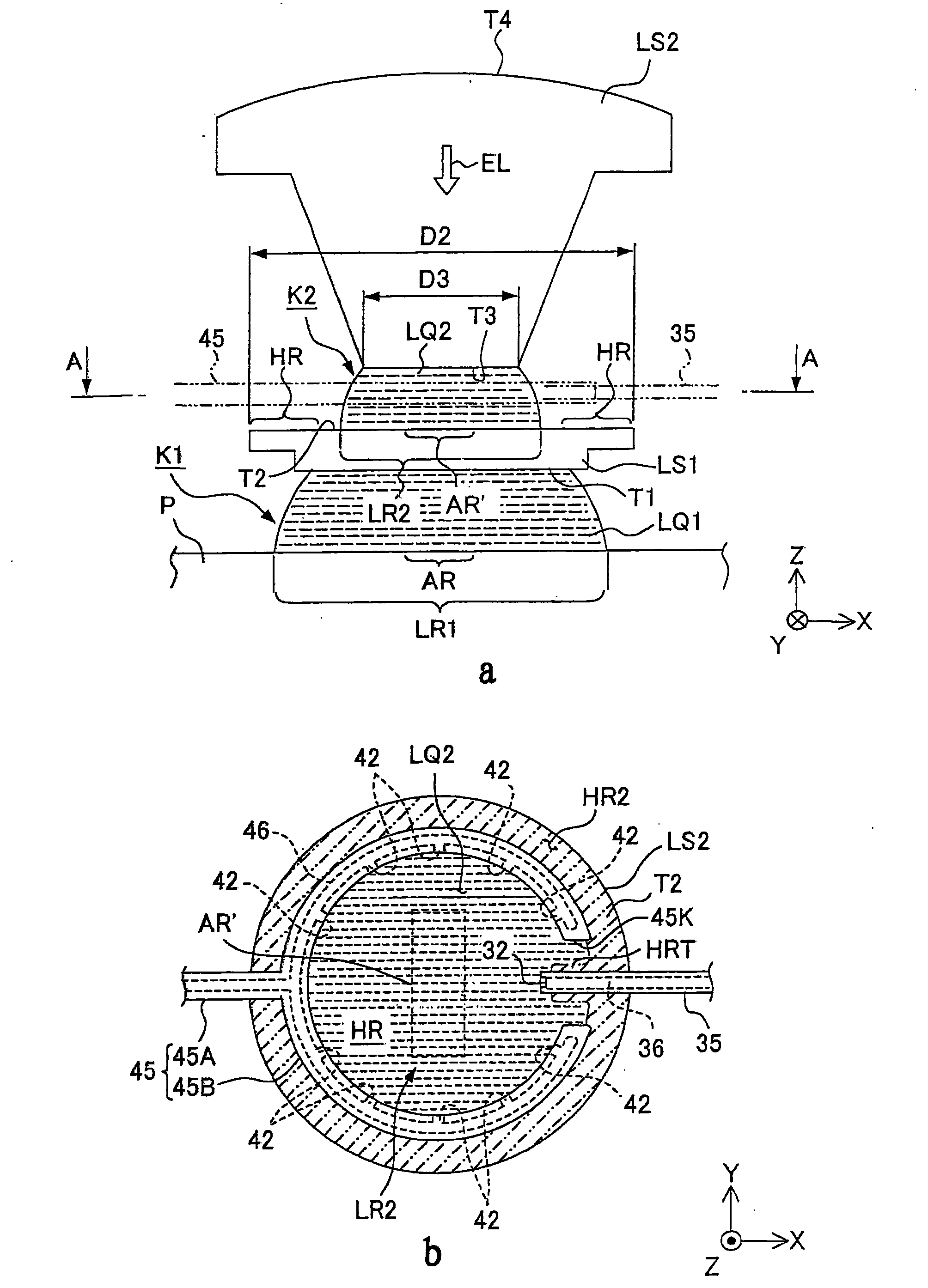
图5a及图5b,是显示用以说明第2液浸机构的图。5a and 5b are diagrams for explaining the second liquid immersion mechanism.
图6是显示第1元件的第2面的俯视图。Fig. 6 is a plan view showing a second surface of the first element.
图7是用以说明第2液浸机构的第2液体回收动作的图。Fig. 7 is a diagram for explaining the second liquid recovery operation of the second liquid immersion mechanism.
图8a及图8b,是用以说明本发明的第1液浸机构的液体回收动作的示意图。8a and 8b are schematic diagrams for explaining the liquid recovery operation of the first liquid immersion mechanism of the present invention.
图9a及图9b,是显示液体回收动作的比较例的示意图。9a and 9b are schematic diagrams showing comparative examples of liquid recovery operations.
图10是显示第1元件的变形例的示意图。FIG. 10 is a schematic diagram showing a modified example of the first element.
图11是从下侧观察嘴构件的变形例的立体图。Fig. 11 is a perspective view of a modified example of the nozzle member viewed from below.
图12是显示本发明另一实施形态的要部截面图。Fig. 12 is a sectional view of main parts showing another embodiment of the present invention.
图13是显示本发明另一实施形态的要部截面图。Fig. 13 is a sectional view of main parts showing another embodiment of the present invention.
图14是显示本发明另一实施形态的要部截面图。Fig. 14 is a sectional view of main parts showing another embodiment of the present invention.
图15是显示半导体元件的制程例的流程图。FIG. 15 is a flow chart showing an example of a manufacturing process of a semiconductor element.
图16是用以说明本发明另一实施形态的第1液体回收机构的回收动作的图。Fig. 16 is a diagram for explaining the recovery operation of the first liquid recovery mechanism according to another embodiment of the present invention.
附图标号:Figure number:
1 第1液浸机构1 The first liquid immersion mechanism
2 第2液浸机构2 The second liquid immersion mechanism
10 第1液体供应机构10 The first liquid supply mechanism
12 第1供应口12 The first supply port
20 第1液体回收机构20 The first liquid recovery mechanism
22 第1回收口22 The first recovery port
25 多孔构件25 Porous components
26 斜面26 inclined plane
30 第2液体供应机构30 The second liquid supply mechanism
32 液体供应口32 Liquid supply port
40 第2液体回收机构40 The second liquid recovery mechanism
42 第2回收口42 The second recovery port
71D,72D 底板部(板状构件)71D, 72D Bottom plate (plate-shaped member)
74 开口部74 opening
75 平坦面(平坦部)75 flat surface (flat part)
76 壁部76 wall
91 第1支撑部91 The first support part
92 第2支撑部92 The second support part
AR 投影区域AR projection area
AR’ 既定区域AR’ established area
AX 光轴AX optical axis
EL 曝光用光EL exposure light
EX 曝光装置EX exposure device
HR1 第1区域HR1 Region 1
HR2 第2区域HR2 Region 2
LQ1 第1液体LQ1 first liquid
LQ2 第2液体LQ2 Second liquid
LR1 第1液浸区域LR1 1st liquid immersion area
LR2 第2液浸区域LR2 2nd liquid immersion area
LS1~LS7 光学元件(元件)LS1~LS7 Optical elements (components)
LS1 第1光学元件(第1元件)LS1 The first optical element (the first element)
LS2 第2光学元件(第2元件)LS2 2nd optical element (2nd element)
P 基板P Substrate
PK 镜筒(支撑构件)PK lens barrel (support member)
PL 投影光学系统PL Projection Optical System
T1 下面(第1面)Below T1 (Side 1)
T2 上面(第2面)T2 top (side 2)
T3 下面Below T3
具体实施方式Detailed ways
以下,虽参照图式说明本发明,但本发明并不限定于此。Hereinafter, although the present invention will be described with reference to the drawings, the present invention is not limited thereto.
图1为显示本实施形态的曝光装置的概略构成图。图1中,曝光装置EX,具有:掩膜载台MST,能保持掩膜M并移动;基板载台PST,能保持基板P并移动;照明光学系统IL,是以曝光用光EL照明保持于掩膜载台MST的掩膜M;投影光学系统PL,将以曝光用光EL照明的掩膜M的图案像投影于保持在基板载台PST的基板P;以及控制装置CONT,是统筹控制曝光装置EX整体的动作。FIG. 1 is a schematic configuration diagram showing an exposure apparatus according to this embodiment. In FIG. 1, the exposure apparatus EX has: a mask stage MST capable of holding and moving a mask M; a substrate stage PST capable of holding and moving a substrate P; The mask M of the mask stage MST; the projection optical system PL projects the pattern image of the mask M illuminated by the exposure light EL onto the substrate P held on the substrate stage PST; and the control device CONT controls the exposure as a whole. The movement of the whole device EX.
本实施形态的曝光装置EX是一适用液浸法的液浸曝光装置,其用以在实质上缩短曝光波长来提高分辨率且在实质上放大焦深,其具备第1液浸机构1,用以将液体LQ1充满于构成投影光学系统PL的复数个光学元件LS1~LS7中、最接近投影光学系统PL的像面的第1光学元件LS1下面T1与基板P间。基板P设于投影光学系统PL的像面侧,第1光学元件LS1的下面T1配置成与基板P表面对向。第1液浸机构1,具备:第1液体供应机构10,是将第1液体LQ1供应至第1光学元件LS1的下面T1与基板P间;以及第1液体回收机构20,是回收以第1液体供应机构10供应的第1液体LQ1。第1液浸机构1的动作,是由控制装置CONT控制。The exposure device EX of this embodiment is a liquid immersion exposure device applicable to the liquid immersion method, which is used to substantially shorten the exposure wavelength to improve the resolution and to substantially enlarge the focal depth. It is equipped with a first liquid immersion mechanism 1 for Liquid LQ1 is filled between the substrate P and the lower surface T1 of the first optical element LS1 closest to the image plane of the projection optical system PL among the plurality of optical elements LS1 to LS7 constituting the projection optical system PL. The substrate P is provided on the image plane side of the projection optical system PL, and the lower surface T1 of the first optical element LS1 is arranged to face the substrate P surface. The first liquid immersion mechanism 1 includes: a first
又,曝光装置EX具备第2液浸机构2,其是将第2液体LQ2充满于第1光学元件LS1与次于第1光学元件LS1接近投影光学系统PL像面的第2光学元件LS2间。第2光学元件LS2配置于第1光学元件LS1上方。亦即,第2光学元件LS2,配置于第1光学元件LS1的光入射面侧,第1光学元件LS1的上面T2,配置成与第2光学元件LS2的下面T3对向。第2液浸机构2,具备:第2液体供应机构30,是将第2液体LQ2供应至第1光学元件LS1与第2光学元件LS2之间;以及第2液体回收机构40,是回收由第2液体供应机构30供应的第2液体LQ2。第2液浸机构2的动作由控制装置CONT控制。In addition, the exposure apparatus EX includes a second liquid immersion mechanism 2 for filling the space between the first optical element LS1 and the second optical element LS2 next to the first optical element LS1 close to the image plane of the projection optical system PL with the second liquid LQ2. The 2nd optical element LS2 is arrange|positioned above the 1st optical element LS1. That is, the second optical element LS2 is arranged on the light incident surface side of the first optical element LS1, and the upper surface T2 of the first optical element LS1 is arranged to face the lower surface T3 of the second optical element LS2. The second liquid immersion mechanism 2 has: a second
又,本实施形态的第1光学元件LS1,可使曝光用光IL透射的无折射力的平行平面板,第1光学元件LS1的下面T1与上面T2是大致平行。此外,投影光学系统PL(包含第1光学元件LS1)的像差等成像特性是控制在既定容许范围内。In addition, the first optical element LS1 of this embodiment is a non-refractive parallel plane plate capable of transmitting the exposure light IL, and the lower surface T1 and the upper surface T2 of the first optical element LS1 are substantially parallel. In addition, imaging characteristics such as aberrations of the projection optical system PL (including the first optical element LS1 ) are controlled within a predetermined allowable range.
本实施形态中,第1光学元件LS1与基板P间的空间(第1空间)K1,以及第1光学元件LS1与第2光学元件LS2间的空间(第2空间)K2,是各为独立的空间。控制装置CONT,能分别独立进行第1液浸机构1对第1空间K1的第1液体LQ1供应动作及回收动作、以及第2液浸机构2对第2空间K2的第2液体LQ2供应动作及回收动作,而不会产生液体(LQ1、LQ2)从第1空间K1及第2空间K2一方出入于另一方的现象。In this embodiment, the space (first space) K1 between the first optical element LS1 and the substrate P, and the space (second space) K2 between the first optical element LS1 and the second optical element LS2 are independent. space. The control device CONT can independently perform the operation of supplying and recovering the first liquid LQ1 from the first liquid immersion mechanism 1 to the first space K1, and the operation of supplying and recovering the second liquid LQ2 from the second liquid immersion mechanism 2 to the second space K2. The recovery operation does not cause the phenomenon that the liquid (LQ1, LQ2) enters or exits from one of the first space K1 and the second space K2 to the other.
曝光装置EX,至少在使掩膜M的图案像投影至基板P上的期间,使用第1液浸机构1,将第1液体LQ1充满于第1光学元件LS1与配置于其像面侧的基板P间来形成第1液浸区域LR1,且使用第2液浸机构2,将第2液体LQ2充满于第1光学元件LS1与第2光学元件LS2之间来形成第2液浸区域LR2。本实施形态中,曝光装置EX,是在包含投影光学系统PL的投影区域AR的基板P上一部分,局部地形成较投影区域AR大且较基板P小的第1液浸区域LR1,亦即采用局部液浸方式。又,本实施形态中,曝光装置EX,是在第1光学元件LS1的上面T2中、仅包含曝光用光EL通过区域AR′的一部分区域,局部性地形成第2液体LQ2的第2液浸区域LR2。曝光装置EX,是通过投影光学系统PL、第2液浸区域LR2的第2液体LQ2、及第1液浸区域LR1的第1液体LQ1,将通过掩膜M的曝光用光EL照射于基板P,由此使掩膜M的图案投影曝光于基板P。The exposure apparatus EX uses the first liquid immersion mechanism 1 to fill the first optical element LS1 and the substrate disposed on the image plane side with the first liquid LQ1 at least while projecting the pattern image of the mask M onto the substrate P. The first liquid immersion region LR1 is formed between P and the second liquid immersion region LR2 is formed by filling the space between the first optical element LS1 and the second optical element LS2 with the second liquid LQ2 using the second liquid immersion mechanism 2 . In the present embodiment, the exposure apparatus EX partially forms the first liquid immersion region LR1 larger than the projection region AR and smaller than the substrate P on a part of the substrate P including the projection region AR of the projection optical system PL. Partial immersion method. In addition, in the present embodiment, the exposure apparatus EX is a second liquid immersion device for locally forming the second liquid LQ2 on a part of the upper surface T2 of the first optical element LS1 including only the exposure light EL passing region AR'. Region LR2. The exposure device EX irradiates the substrate P with the exposure light EL passing through the mask M through the projection optical system PL, the second liquid LQ2 in the second liquid immersion region LR2, and the first liquid LQ1 in the first liquid immersion region LR1. , thereby projectingly exposing the pattern of the mask M to the substrate P.
于投影光学系统PL的像面侧附近、具体而言是投影光学系统PL的像面侧端部的光学元件LS1附近,配置有详述于后的嘴构件70。嘴构件70是一环状构件,其在基板P(基板载台PST)上方设置成包围投影光学系统PL前端部周缘。本实施形态中,嘴构件70是构成第1液浸机构的一部分。In the vicinity of the image plane side of projection optical system PL, specifically, in the vicinity of optical element LS1 at the end portion of projection optical system PL on the image plane side,
此处,本实施形态是以使用扫描型曝光装置(即扫描步进机)作为曝光装置EX的情形为例来说明,该扫描型曝光装置,是一边使掩膜M与基板P往扫描方向的彼此互异的方向(反方向)同步移动,一边将形成于掩膜M的图案曝光于基板P。以下说明中,将与投影光学系统PL的光轴AX一致的方向设为Z轴方向、将在垂直于Z轴方向的平面内、掩膜M与基板P同步移动的方向(扫描方向)设为X轴方向、将垂直于Z轴方向及X轴方向的方向(非扫描方向)设为Y轴方向。又,将绕X轴、Y轴、及Z轴周围的旋转(倾斜)方向分别设为θX、θY、以及θZ方向。Here, this embodiment will be described by taking the case of using a scanning type exposure device (that is, a scanning stepper) as the exposure device EX as an example. The patterns formed on the mask M are exposed to the substrate P while moving in directions (reverse directions) different from each other in synchronization. In the following description, the direction coincident with the optical axis AX of the projection optical system PL is referred to as the Z-axis direction, and the direction (scanning direction) in which the mask M and the substrate P move synchronously in a plane perpendicular to the Z-axis direction is referred to as Let the X-axis direction and the direction (non-scanning direction) perpendicular to the Z-axis direction and the X-axis direction be the Y-axis direction. Also, the rotation (tilt) directions around the X-axis, Y-axis, and Z-axis are defined as θX, θY, and θZ directions, respectively.
曝光装置EX,具备:设于地面上的底座BP、以及设于该底座BP上的主柱架9。于主柱架9形成有向内侧突出的上侧段部7及下侧段部8。照明光学系统IL,是以曝光用光EL照明由掩膜载台MST所支撑的掩膜M,其由固定于主柱架9上部的框架3支撑。The exposure apparatus EX is equipped with the base BP installed on the ground, and the main post 9 provided on this base BP. The upper side section 7 and the lower side section 8 protruding inwardly are formed on the main column frame 9 . The illumination optical system IL illuminates the mask M supported by the mask stage MST with the exposure light EL, and is supported by the frame 3 fixed to the upper part of the main column frame 9 .
照明光学系统IL,具有:射出曝光用光EL的曝光用光源、使从曝光用光源射出的曝光用光EL的照度均一化的光学积分器、使来自光学积分器的曝光用光EL聚光的聚光透镜、中继透镜系统、将曝光用光EL所形成的掩膜M上的照明区域设定成狭缝状的可变视野光栅等。掩膜M上的既定照明区域,是由照明光学系统IL以均一照度分布的曝光用光EL来照明。作为从照明光学系统IL射出的曝光用光EL,例如使用从水银灯射出的亮线(g线、h线、i线)及KrF准分子雷射光(波长248nm)等远紫外光(DUV光),或ArF准分子雷射光(波长193nm)及F2雷射光(波长157nm)等真空紫外光(VUV光)等。本实施形态是使用ArF准分子雷射光。The illumination optical system IL includes: an exposure light source that emits exposure light EL, an optical integrator that uniforms the illuminance of the exposure light EL emitted from the exposure light source, and a device that condenses the exposure light EL from the optical integrator. A condenser lens, a relay lens system, a variable field of view grating for setting the illumination area on the mask M formed by the exposure light EL in a slit shape, and the like. A predetermined illumination area on the mask M is illuminated by the illumination optical system IL with the exposure light EL having a uniform illuminance distribution. As the exposure light EL emitted from the illumination optical system IL, for example, bright lines (g-line, h-line, i-line) emitted from a mercury lamp and deep ultraviolet light (DUV light) such as KrF excimer laser light (wavelength 248nm) are used, Or vacuum ultraviolet light (VUV light) such as ArF excimer laser light (wavelength 193nm) and F 2 laser light (wavelength 157nm), etc. In this embodiment, ArF excimer laser light is used.
本实施形态中,是使用纯水来作为从第1液体供应装置10所供应的第1液体LQ1、及从第2液体供应装置30所供应的第2液体LQ2,亦即,本实施形态中,第1液体LQ1与第2液体是同一液体。纯水不但能使ArF准分子雷射光透射,也能使亮线(g线、h线、i线)及KrF准分子雷射光(波长248nm)等远紫外光(DUV光)透射。In this embodiment, pure water is used as the first liquid LQ1 supplied from the first
掩膜载台MST,是能保持掩膜M并移动,由例如真空吸附(或静电吸附)方式来固定掩膜M。于掩膜载台MST下面,设有复数个非接触轴承的空气轴承(air bearing)85。掩膜载台MST,是由空气轴承85以非接触方式支撑于掩膜台4上面(导引面)。于掩膜载台MST及掩膜台4的中央部,分别形成有使掩膜M的图案像通过的开口部MK1,MK2。掩膜台4是通过防振装置86支撑于主柱架9的上侧段部7。亦即,掩膜载台MST是通过防振装置86及掩膜台4而支撑于主柱架9(上侧段部7)的构成。又,由防振装置86,来将掩膜台4在振动上与主柱架9分离,以使主柱架9的振动不会传达至支撑掩膜载台MST的掩膜台4。The mask stage MST is capable of holding and moving the mask M, and fixes the mask M by, for example, vacuum adsorption (or electrostatic adsorption). Under the mask stage MST, there are a plurality of non-contact air bearings (air bearing) 85 . The mask stage MST is supported on the upper surface (guide surface) of the mask stage 4 by the
掩膜载台MST,由驱动控制装置CONT所控制的包含线性马达等掩膜载台驱动装置MSTD,能在保持掩膜M的状态下,在掩膜台4上与投影光学系统PL的光轴AX垂直的平面内、亦即XY平面内,进行2维移动及微幅旋转于θZ方向。掩膜载台MST,能以指定的扫描速度移动于X轴方向,并具有掩膜M全面至少能横越投影光学系统PL的光轴AX的X轴方向移动行程。The mask stage MST, the mask stage drive device MSTD including a linear motor controlled by the drive control device CONT, can hold the mask M on the mask stage 4 and the optical axis of the projection optical system PL In the plane perpendicular to AX, that is, in the XY plane, two-dimensional movement and slight rotation are performed in the θZ direction. Mask stage MST is movable in the X-axis direction at a predetermined scanning speed, and has a movement stroke in the X-axis direction at least across the entire surface of mask M across optical axis AX of projection optical system PL.
于掩膜载台MST上,设有与掩膜载台MST一起移动的移动镜81。又,在与移动镜81对向的位置设置雷射干涉仪82。掩膜载台MST上的掩膜M的2维方向位置、及θZ方向的旋转角(视情形不同有时也包含θX、θY方向的旋转角),是由雷射干涉仪82以实时方式测量。雷射干涉仪82的测量结果输出至控制装置CONT。控制装置CONT,即根据雷射干涉仪82的测量结果来驱动掩膜载台驱动装置MSTD,由此进行保持于掩膜载台MST的掩膜M的位置控制。On mask stage MST, movable mirror 81 that moves together with mask stage MST is provided. Also, a laser interferometer 82 is provided at a position facing the movable mirror 81 . The two-dimensional position of the mask M on the mask stage MST and the rotation angle in the θZ direction (including the rotation angle in the θX and θY directions depending on the situation) are measured by the laser interferometer 82 in real time. The measurement result of the laser interferometer 82 is output to the control device CONT. Control device CONT controls the position of mask M held on mask stage MST by driving mask stage drive device MSTD based on the measurement result of laser interferometer 82 .
投影光学系统PL,以既定的投影倍率β将掩膜M的图案投影曝光于基板P。投影光学系统PL以复数个光学元件LS1~LS7(包含设于基板P侧前端部的第1光学元件LS1)构成,复数个光学元件LS1~LS7是以镜筒PK支撑。本实施形态中,投影光学系统PL,是投影倍率β例如为1/4、1/5、或1/8的缩小系统。此外,投影光学系统PL也可为等倍系统及放大系统的任一者。又,投影光学系统PL,也可是包含折射元件与反射元件的折反射系统、不包含反射元件的折射系统、不包含折射元件的反射系统的任一者。从照明光学系统IL射出的曝光用光EL,由物体面侧射入投影光学系统PL,在通过复数个光学元件LS7~LS1后,从投影光学系统PL的像面侧射出,而到达基板P上。具体而言,曝光用光EL是在分别通过复数个光学元件LS7~LS3之后,通过第2光学元件LS2的上面T4的既定区域,并通过下面T3的既定区域后,射入第2液浸区域LR2。通过第2液浸区域LR2的曝光用光EL,在通过第1光学元件LS1的上面T2的既定区域后,通过下面T1的既定区域,并射入第1液浸区域LR1后到达基板P上。The projection optical system PL projects and exposes the pattern of the mask M on the substrate P at a predetermined projection magnification β. Projection optical system PL is comprised by several optical elements LS1-LS7 (including the 1st optical element LS1 provided in the front-end|tip part of the board|substrate P side), and several optical elements LS1-LS7 are supported by lens barrel PK. In the present embodiment, projection optical system PL is a reduction system in which projection magnification β is, for example, 1/4, 1/5, or 1/8. In addition, projection optical system PL may be any one of a constant magnification system and a magnification system. In addition, projection optical system PL may be any of a catadioptric system including a refractive element and a reflective element, a refractive system not including a reflective element, and a reflective system not including a refractive element. The exposure light EL emitted from the illumination optical system IL enters the projection optical system PL from the object surface side, passes through a plurality of optical elements LS7-LS1, is emitted from the image surface side of the projection optical system PL, and reaches the substrate P. . Specifically, after passing through a plurality of optical elements LS7 to LS3, the exposure light EL passes through a predetermined region of the upper surface T4 of the second optical element LS2, passes through a predetermined region of the lower surface T3, and enters the second liquid immersion region. LR2. The exposure light EL passing through the second liquid immersion region LR2 passes through a predetermined region of the upper surface T2 of the first optical element LS1 , passes through a predetermined region of the lower surface T1 , enters the first liquid immersion region LR1 , and reaches the substrate P.
于保持投影光学系统PL的镜筒PK外周设有突缘PF,投影光学系统PL通过此突缘PF支撑于镜筒台5。镜筒台5通过防振装置87支撑于主柱架9的下侧段部8。亦即,投影光学系统PL是通过防振装置87及镜筒台5而支撑于主柱架9(下侧段部8)的构成。又,由防振装置87,来将镜筒台5在振动上与主柱架9分离,以使主柱架9的振动不会传达至支撑投影光学系统PL的镜筒台5。A flange PF is provided on the outer periphery of the barrel PK holding the projection optical system PL, and the projection optical system PL is supported by the barrel stand 5 through the flange PF. The lens tube stand 5 is supported by the lower section 8 of the main column frame 9 via the anti-vibration device 87 . That is, projection optical system PL is configured to be supported by main column frame 9 (lower side section 8 ) via anti-vibration device 87 and barrel stand 5 . Also, the vibration isolator 87 separates the tube stand 5 from the main column frame 9 in terms of vibration so that the vibration of the main column frame 9 is not transmitted to the tube stand 5 supporting the projection optical system PL.
基板载台PST,能支撑保持基板P的基板保持具PH并移动,由例如真空吸附(或静电吸附)方式来保持基板P。于基板载台PST下面,设有复数个非接触轴承的空气轴承88。基板载台PST,是由空气轴承88以非接触方式支撑于基板台6上面(导引面)。基板台6是通过防振装置89支撑于底座BP上。又,由防振装置89,来将基板台6在振动上与主柱架9分离,以使底座BP(地板面)或主柱架9的振动不会传达至支撑基板载台PST的基板台6。The substrate stage PST can support and move the substrate holder PH holding the substrate P, and holds the substrate P by, for example, vacuum adsorption (or electrostatic adsorption). Below the substrate stage PST, a plurality of non-contact bearing air bearings 88 are provided. The substrate stage PST is supported on the upper surface (guide surface) of the substrate stage 6 by the air bearing 88 in a non-contact manner. The substrate table 6 is supported on the base BP through the anti-vibration device 89 . In addition, the substrate stage 6 is separated from the main pillar frame 9 in terms of vibration by the anti-vibration device 89 so that the vibration of the base BP (floor surface) or the main pillar frame 9 is not transmitted to the substrate stage supporting the substrate stage PST. 6.
基板载台PST,由驱动控制装置CONT所控制的包含线性马达等基板载台驱动装置PSTD,能在通过基板保持具PH在保持基板P的状态下,在基板台6上的XY平面内进行2维移动及微幅旋转于θZ方向。进一步,基板载台PST也可移动于Z轴方向、θX方向、以及θY方向。The substrate stage PST, the substrate stage drive device PSTD including a linear motor controlled by the drive control device CONT, can perform 2 steps in the XY plane on the substrate stage 6 while holding the substrate P by the substrate holder PH. Dimensional movement and slight rotation in the θZ direction. Furthermore, the substrate stage PST is also movable in the Z-axis direction, the θX direction, and the θY direction.
在基板载台PST上,设有与基板载台PST一起相对投影光学系统PL移动的移动镜83。又,在与移动镜83对向的位置设有雷射干涉计84。基板载台PST上的基板P在2维方向的位置及旋转角,是由雷射干涉计84以实时方式测量。又,虽未图标,曝光装置EX,是具备焦点位准检测系统,其用以检测支撑于基板载台PST的基板P的表面位置信息。作为焦点位准检测系统,可采用从斜方向将检测光照射于基板P表面的斜入射方式、也可采用静电容量型传感器的方式等。焦点位准检测系统,是通过第1液体LQ1、或在不通过第1液体LQ1的状态下,检测出基板P表面的Z轴方向的位置信息、以及基板P的θX及θY方向的倾斜信息。当是在不通过液体LQ1的状态下检测基板P表面的面信息的焦点位准检测系统时,也可是在离开投影光学系统PL的位置检测基板P表面的面信息。在离开投影光学系统PL的位置检测基板P表面的面信息的曝光装置,例如揭示于美国专利第6,674,510号,在本国际申请案的指定或选择的国家法令所容许的范围内,援用该文献的记载内容来作为本文记载的一部分。On the substrate stage PST, a moving mirror 83 that moves relative to the projection optical system PL together with the substrate stage PST is provided. Also, a laser interferometer 84 is provided at a position facing the movable mirror 83 . The two-dimensional position and rotation angle of the substrate P on the substrate stage PST are measured in real time by the laser interferometer 84 . Also, although not shown, the exposure apparatus EX is provided with a focus level detection system for detecting surface position information of the substrate P supported on the substrate stage PST. As the focus level detection system, an oblique incidence method in which detection light is irradiated on the surface of the substrate P from an oblique direction, a method using a capacitive sensor, or the like may be used. The focus position detection system detects the position information of the surface of the substrate P in the Z-axis direction and the inclination information of the substrate P in the θX and θY directions through the first liquid LQ1 or without passing through the first liquid LQ1. In the case of a focus level detection system that detects surface information on the surface of the substrate P without passing through the liquid LQ1 , the surface information on the surface of the substrate P may be detected at a position away from the projection optical system PL. An exposure device that detects surface information on the surface of the substrate P at a position away from the projection optical system PL is disclosed, for example, in U.S. Patent No. 6,674,510. To the extent permitted by the national laws and regulations specified or selected in this international application, the contents of this document are cited. The recorded content is included as part of this document.
雷射干涉仪84的测量结果输出至控制装置CONT。焦点位准检测系统的检测结果也输出至控制装置CONT。控制装置CONT,根据焦点位准检测系统的检测结果驱动基板载台驱动装置PSTD,以控制基板P的焦点位置及倾斜角,使基板P表面与投影光学系统PL的像面一致,且根据雷射干涉仪84的测量结果,进行基板P的X轴方向及Y轴方向的位置控制。The measurement result of the laser interferometer 84 is output to the control device CONT. The detection result of the focus level detection system is also output to the control device CONT. The control device CONT drives the substrate stage driving device PSTD according to the detection result of the focus level detection system to control the focus position and inclination angle of the substrate P, so that the surface of the substrate P is consistent with the image plane of the projection optical system PL, and according to the laser The measurement results of the interferometer 84 are used to control the position of the substrate P in the X-axis direction and the Y-axis direction.
于基板载台PST上设有凹部90,用以保持基板P的基板保持具PH即配置于凹部90。又,基板载台PST中除了凹部90以外的上面91,是一与保持于基板保持具PH的基板P表面大致相同高度(同一面高)的平坦面(平坦部)。又,本实施形态中,移动镜83的上面也设置成与基板载台PST的上面91为大致同一面。A concave portion 90 is provided on the substrate stage PST, and the substrate holder PH for holding the substrate P is arranged in the concave portion 90 . In addition, the
由于在基板P周围设有与基板P表面大致同一面的上面91,因此即使是对基板P的边缘区域进行液浸曝光时,由于在基板P的边缘部位外侧几乎没有段差,因此能将液体LQ保持于投影光学系统PL的像面侧,良好地形成液浸区域LR1。此外,只要能维持液浸区域LR1,于基板P表面与基板载台PST的上面91间也可存在段差。又,在基板P的边缘部与设于该基板P周围的平坦面(上面)91之间虽有0.1~2mm左右的间隙,但由液体LQ的表面张力,液体LQ几乎不会流入该间隙,即使对基板P的周缘附近进行曝光时,也可由上面91将液体LQ保持于投影光学系统PL下。Since the
第1液浸机构1的第1液体供应机构10,是将第1液体LQ1供应至投影光学系统PL的第1光学元件LS1与基板P间的第1空间K1,其具备:能送出第1液体LQ1的第1液体供应部11、以及其一端部连接于第1液体供应部11的第1供应管13。第1供应管13的另一端部连接于嘴构件70。本实施形态中,第1液体供应机构10是供应纯水,第1液体供应部11具有纯水制造装置、以及调整所供应的第1液体(纯水)LQ1温度的调温装置等。此外,只要能满足既定品质条件,也可不将纯水制造装置设于曝光装置EX,而是使用配置有曝光装置EX的工厂内的纯水制造装置(施力装置)。第1液体供应机构10(第1液体供应部11)的动作是由控制装置CONT控制。为将第1液浸区域LR1形成于基板P上,第1液体供应机构10,在控制装置CONT的控制下,将既定量第1液体LQ1供应至配置在投影光学系统PL像面侧的基板P上。The first
又,于第1供应管13途中设有称为mass flow controller的流量控制器16,其用以控制从第1液体供应部11送至投影光学系统PL像面侧的每一单位时间的液体量。流量控制器16的液体供应量的控制,是根据控制装置CONT的指令讯号所进行。In addition, a
第1液浸机构1的液体回收机构20,是用以回收投影光学系统PL的像面侧的第1液体LQ1。第1液体回收机构20,具备能回收第1液体LQ1的第1液体回收部21、以及其一端部连接于第1液体回收部21的第1回收管23。第1回收管23的另一端部则连接于嘴构件70。第1液体回收部21,例如具备:真空泵等真空系统(吸引装置)、以及将所回收的第1液体LQ1与气体分离的气液分离器等。此外,也可不将真空系统或气液分离器等全部设于曝光装置EX,而使用配置有曝光装置EX的工厂内的设备来替代其至少一部分。第1液体回收机构20(第1液体回收部21)的动作是由控制装置CONT控制。为将第1液浸区域LR1形成于基板P上,第1液体回收机构20,在控制装置CONT的控制下,将第1液体供应机构10所供应的基板P上的第1液体LQ1回收既定量。The
第2液浸机构2的第2液体供应机构30,是将第2液体LQ2供应至投影光学系统PL的第2光学元件LS2与第1光学元件LS1之间的第2空间K1。第2液体供应机构30,具备:能送出第2液体LQ2的第2液体供应部31、以及其一端部连接于第2液体供应部31的第2供应管33。第2供应管33的另一端部,则通过后述供应流路34等,连接于第1光学元件LS1与第2光学元件LS2间的第2空间K2。与第1液体供应机构10同样地,第2液体供应机构30是供应纯水。第2液体供应部31具有纯水制造装置、以及调整所供应的第2液体(纯水)LQ2温度的调温装置等。此外,也可不将纯水制造装置设于曝光装置EX,而是使用配置有曝光装置EX的工厂内的纯水制造装置(施力装置)。第2液体供应机构30(第2液体供应部31)的动作是由控制装置CONT控制。为将第2液浸区域LR2形成于第1光学元件LS1的上面T2上,第2液体供应机构30,是在控制装置CONT的控制下,将既定量第2液体LQ2供应至第1光学元件LS1的上面T2上。The second
此外,纯水制造装置也可共通使用于第1液浸机构与第2液浸机构。In addition, the pure water production device may be used in common for the first liquid immersion mechanism and the second liquid immersion mechanism.
又,于第2供应管33的途中也可设置流量控制器,其用以控制从第2液体供应部31送出、供应至第2空间K2的每一单位时间的液体量。In addition, a flow controller may be provided in the middle of the
第2液浸机构2的液体回收机构40,是从投影光学系统PL的第2光学元件LS2与第1光学元件LS1间的第2空间K2回收第2液体LQ2。第2液体回收机构40,具备能回收第2液体LQ2的第2液体回收部41、以及其一端部连接于第2液体回收部41的第2回收管43。第2回收管43的另一端部,是通过后述回收流路44等,连接于第1光学元件LS1与第2光学元件LS2间的第2空间K2。第2液体回收部41,例如具备:真空泵等真空系统(吸引装置)、以及将所回收的第2液体LQ2与气体分离的气液分离器等。此外,也可不将真空系统或气液分离器等全部设于曝光装置EX,而使用配置有曝光装置EX的工厂内的设备来替代其至少一部分。第2液体回收机构40(第2液体回收部41)的动作是由控制装置CONT控制。第2液体回收机构40,在控制装置CONT的控制下,回收第2液体供应机构30所供应的第1光学元件LS1上面T2上的第2液体LQ2。The
嘴构件70是被嘴保持具96保持,该嘴保持具96连接于主柱架9的下侧段部8。通过嘴保持具96保持嘴构件70的主柱架9、与通过突缘PF支撑投影光学系统PL的镜筒PK的镜筒台5,是通过防振装置87在振动上分离。因此,可防止在嘴构件70产生的振动传达至投影光学系统PL。又,通过嘴保持具96支撑嘴构件70的主柱架9、与支撑基板载台PST的基板台6,是通过防振装置89在振动上分离。因此,可防止在嘴构件70产生的振动通过主柱架9及底座BP而传达至基板载台PST。又,通过嘴保持具96支撑嘴构件70的主柱架9、与支撑掩膜载台MST的掩膜台4,是通过防振装置86在振动上分离。因此,可防止嘴构件70产生的振动通过主柱架9传达至掩膜载台MST。The
其次,参照图2、图3及图4说明第1液浸机构1及嘴构件70。图2是显示嘴构件70附近的概略立体图的部分截断图、图3是从下侧观察嘴构件70的立体图、图4是侧截面图。Next, the first liquid immersion mechanism 1 and the
嘴构件70,配置于投影光学系统PL的像面侧前端部附近,是一于基板P(基板载台PST)上方配置成包围投影光学系统PL周围的环状构件。本实施形态中,嘴构件70是构成第1液浸机构1的一部分。于嘴构件70中央部具有能配置投影光学系统PL的孔部70H。如图4所示,第1光学元件LS1与第2光学元件LS2是以同一镜筒(支撑构件)PK所支撑,本实施形态中,设置成嘴构件70的孔部70H的内侧面70T与镜筒PK的侧面PKT对向。又,在嘴构件70的孔部70H的内侧面70T与投影光学系统PL的镜筒PK的侧面PKT之间设有间隙。此间隙,是为了在振动上分离投影光学系统PL与嘴构件70而设置。由此,可防止在嘴构件70产生的振动直接传达至投影光学系统PL。The
此外,嘴构件70的孔部70H内侧面,对液体LQ具有拨液性(拨水性),可抑制液体渗入投影光学系统PL侧面与嘴构件70内侧面的间隙。In addition, the inner surface of the
于嘴构件70下面,形成有用以供应第1液体LQ1的液体供应口12、及用以回收第1液体LQ1的液体回收口22。以下说明中,将第1液浸机构1的液体供应口12适当称为第1供应口12,将第1液浸机构1的液体回收口22适当称为第1回收口22。A
于嘴构件70内部,形成有连接于第1供应口12的第1供应流路14、以及连接第1回收口22的第1回收流路24。又,于第1供应流路14连接第1供应管13另一端,于第1回收流路24连接第1回收管23另一端。第1供应口12、第1供应流路14、以及第1供应管13,构成第1液体供应机构10(第1液浸机构1)的一部分,第1回收口22、第1回收流路24、以及第1回收管23,构成第1液体回收机构20(第1液浸机构1)的一部分。Inside the
第1供应口12,是在被基板载台PST支撑的基板P上方,设置成与该基板P表面对向。第1供应口12与基板P表面隔着既定距离。第1供应口12,配置成包围曝光用光EL所照射的投影光学系统PL的投影区域AR。本实施形态中,如图3所示,第1供应口12,是于嘴构件70下面配置成包围投影区域AR的环形狭缝状。又,本实施形态中,投影区域AR,是设定成以Y轴方向(非扫描方向)为长边方向的矩形。The
第1供应流路14,具备其一部分连接于第1供应管13的另一端的缓冲流路部14H;以及其上端部连接于缓冲流路部14H、下端部连接于第1供应口12的倾斜流路部14S。倾斜流路部14S具有对应第1供应口12的形状,其沿XY平面的截面,形成为包围第1光学元件LS1的环状狭缝。倾斜流路部14S,具有与配置于其内侧的第1光学元件LS1侧面对应的倾斜角度,从图4的侧截面图可知,形成为与投影光学系统PL的光轴AX的距离越长而与基板P表面的间隔越大。The first
缓冲流路部14H,以包围倾斜流路部14S上端部的方式设置于其外侧,是一形成为沿XY方向(水平方向)扩张的空间部。缓冲流路部14H内侧(光轴AX侧)与倾斜流路部14S上端部连接,其连接部为一弯曲角部17。又,在其连接部(弯曲角)17附近,具体而言是缓冲流路部14H的内侧(光轴AX侧)区域,设置有形成为包围倾斜流路部14S上端部的堤防部15。堤防部15,设置成从缓冲流路部14H底面往+Z方向突出。堤防部15与嘴构件上面(后述的顶板部72B)之间,分隔出较缓冲流路部14H窄的狭窄流路部14N。The buffer
本实施形态中,嘴构件70,是将第1构件71与第2构件72组合而形成。第1、第2构件71,72,例如可由铝、钛、不锈钢、杜拉铝、或至少含上述中的二者的合金来形成。In this embodiment, the
第1构件71,具有:侧板部71A、其外侧端部连接于侧板部71A上部的既定位置的顶板部71B、其上端部连接于顶板部71B内侧端部的倾斜板部71C、以及连接于倾斜板部71C下端部的底板部71D(参照图3),上述各板部是彼此接合成一体。第2构件72,具有:其外侧端部连接于第1构件71上端部的顶板部72B、其上端部连接于顶板部72B内侧端部的倾斜板部72C、以及连接于倾斜板部72C下端部的底板部(平板部)72D,上述各板部是彼此接合成一体。又,以第1构件71的顶板部71B形成缓冲流路部14H的底面、以第2构件72的顶板部72B下面形成缓冲流路部14H的顶面。又,以第1构件71的倾斜板部71C上面(朝向投影光学系统PL侧的面)形成倾斜流路部14S的底面、以第2构件72的倾斜板部72C下面(与投影光学系统PL相反侧的面)形成倾斜流路部14S的顶面。第1构件71的倾斜板部71C及第2构件72的倾斜板部72C分别形成为研钵状。由组合上述第1、第2构件71,72来形成狭缝状供应流路14。又,缓冲流路部14H外侧,被第1构件71的侧板部71A上部区域封闭,第2构件72的倾斜板部72C上面(也即嘴构件70的内侧面70T),与投影光学系统PL的镜筒PK的侧面PKT对向。The
第1回收口22,是在支撑于基板载台PST的基板P上方,设置成与该基板P表面对向。第1回收口22与基板P表面隔着既定距离。第1回收口22是相对投影光学系统PL的投影区域AR,以从第1供应口12离开的方式设置于第1供应口12外侧,并形成为包围第1供应口12及曝光用光EL所照射的投影区域AR。具体而言,由第1构件71的侧板71A、顶板部71B、以及倾斜板部71C,来形成向下开口的空间部24,由空间部24的前述开口部来形成第1回收口22,并由前述空间部24形成第1回收流路24。又,于第1回收流路(空间部)24的一部分连接有第1回收管23的另一端。The
于第1回收口22配置有覆盖该第1回收口22的具复数个孔的多孔构件25。多孔构件25是由具复数个孔的网状构件构成。作为多孔构件25,例如能由形成蜂巢形图案(由大致六角形的复数个孔所构成)的网状构件来构成。多孔构件25形成为薄板状,例如为具有100μm左右的厚度。A
多孔构件25,是能由对构成多孔构件25基材(由不锈钢(例如SUS316)等构成)的板构件施以凿孔加工来形成。又,也能于第1回收口22重叠配置复数个薄板状多孔构件25。又,也可对多孔构件25施以用来抑制杂质溶于第1液体LQ1的表面处理、或施以用来提高亲液性的表面处理。作为此种表面处理,有使氧化铬附着于多孔构件25的处理,例如神钢环境对策股份有限公司的「GOLDEP」处理、或「GOLDEP WHITE」处理。由施以此种表面处理,而能防止多孔构件25的杂质溶于第1液体LQ1等不良情形产生。又,也可对嘴构件70(第1、第2构件71,72)施以上述表面处理。The
此外,也可使用杂质较不会溶于第1液体LQ1的材料(钛等)来形成多孔构件25。In addition, the
嘴构件70为俯视四角形状。如图3所示,第1回收口22,是于嘴构件70下面形成为包围投影区域AR及第1供应口12的俯视框状(「口」字形)。又,于该第1回收口22配置有薄板状的多孔构件25。又,在第1回收口22(多孔构件25)与第1供应口12之间,配置有第1构件71的底板部71D。第1供应口12,是在第1构件71的底板部71D与第2构件72的底板部72D间形成为俯视环状的狭缝。The
嘴构件70中,底板部71D,72D的各与基板P对向的面(下面),为平行于XY平面的平坦面。亦即,嘴构件70所具备的底板部71D,72D,是具有形成为与基板载台PST所支撑的基板P表面(XY平面)对向、且与基板P表面大致平行的下面。又,本实施形态中,底板部71D下面与底板部72D下面为大致同一面高,且是一与配置于基板载台PST的基板P表面间的间隙为最小的部分。由此,能将第1液体LQ1良好地保持在底板部71D,72D下面与基板P之间,以形成第1液浸区域LR1。以下说明中,将形成为与基板载台PST所支撑的基板P表面对向、且与基板P表面(XY平面)大致平行的底板部71D,72D下面(平坦部),适当并称为「平坦面75」。In the
平坦面75,是配置于嘴构件70中最接近基板载台PST所支撑的基板P处的面。且本实施形态中,由于底板部71D下面与底板部72D下面为大致同一面高,因此虽将底板部71D下面及底板部72D下面一起当作平坦面75,但也可于底板部71D下面配置多孔构件25,来作为第1回收口22的一部分。此时,仅有底板部72D的下面为平坦面75。The
多孔构件25,具有与支撑于基板载台PST的基板P对向的下面26。又,多孔构件25,是以其下面26对支撑于基板载台PST的基板P表面(也即XY平面)呈倾斜的方式设于第1回收口22。亦即,设于第1回收口22的多孔构件25,具有与支撑于基板载台PST的基板P表面对向的斜面(下面)26。第1液体LQ1,是通过配置于第1回收口22的多孔构件25的斜面26而被回收。亦即,第1回收口22是形成于斜面26的构成。又,第1回收口22,由于是形成为包围曝光用光EL所照射的投影区域AR,因此配置于该第1回收口22的多孔构件25的斜面26,是一形成为包围曝光用光EL所照射的投影区域AR的构成。The
与基板P对向的多孔构件25的斜面26,是形成为与投影光学系统PL(曝光用光EL)的光轴AX的距离越长而与基板P表面的间隔越大。如图3所示,本实施形态中,第1回收口22是形成俯视呈「口」字形,并组合4枚多孔构件25A~25D配置于第1回收孔22。其中,相对投影区域AR的X轴方向(扫描方向)分别配置于两侧的多孔构件25A,25C,是配置成其表面与XZ平面正交、且与光轴AX的距离越长而与基板P表面的间隔越大。又,相对投影区域AR分别配置于Y轴方向两侧的多孔构件25B,25D,是配置成其表面与YZ平面正交、且与光轴AX的距离越长而与基板P表面的间隔越大。The
连接于第1构件71的倾斜板部71C下端部的底板部71D下面与侧板部71A下端部,是设置成于Z轴方向大致相同位置(等高)。又,多孔构件25,是以其斜面26内缘部与底板部71D下面(平坦面75)为大致同高的方式、且以斜面26内缘部与底板部71D下面(平坦面75)连续的方式,安装于嘴构件70的第1回收口22。亦即,平坦面75是与多孔构件25的斜面26连续地形成。又,多孔构件25,是配置成与光轴AX的距离越长而与基板P表面的间隔越大。又,于斜面26(多孔构件25)的外缘部外侧,设有由侧板部71A下部的一部分区域所形成的壁部76。壁部76是以包围多孔构件25(斜面26)的方式设置于其周缘,其相对投影区域AR设于第1回收口22外侧,用以抑制第1液体LQ1的漏出。The lower surface of the
形成平坦面75的底板部72D的一部分,是在Z轴方向配置于投影光学系统PL的第1光学元件LS1下面T1与基板P之间。亦即,形成平坦面75的底板部72的一部分,是潜入投影光学系统PL的光学元件LS1的下面T1之下。又,在形成平坦面75的底板部72D的中央部,形成有使曝光用光EL通过的开口部74。开口部74,具有对应投影区域AR的形状,在本实施形态中形成为以Y轴方向(非扫描方向)为长边方向的椭圆状。开口部74是形成为比投影区域AR大,由此使通过投影光学系统PL的曝光用光EL不会被底板部72D遮蔽,而能到达基板P上。亦即,形成平坦面75的底板部72D,是在不妨碍曝光用光EL的光路的位置,配置成包围曝光用光EL的光路、且潜入第1光学元件LS1的下面T1之下。换言之,平坦面75是在第1光学元件LS1的下面T1与基板P之间配置成包围投影区域AR。又,底板部72D,是以其下面为平坦面75配置成与基板P表面对向,并设置成不与第1光学元件LS1下面T1及基板P接触。此外,开口部74的边缘部74E可是直角状,或形成为锐角或圆弧状皆可。A part of
又,平坦面75,是配置于曝光用光EL所照射的投影区域AR与配置于第1回收口22的多孔构件25的斜面26间。第1回收口22是相对投影区域AR在平坦面75外侧、且配置成包围着平坦面75。又,第1供应口12,是相对投影区域AR配置于平坦面75(底板部72D)外侧。第1供应口12,设于投影光学系统PL的投影区域AR与第1回收口22间,用以形成第1液浸区域LR1的第1液体LQ1,通过第1供应口12被供应至投影光学系统PL的投影区域AR与第1回收口22间。Moreover, the
且本实施形态中,虽第1回收口22是形成为口字形且配置成包围平坦面75,但只要是相对投影区域AR位于平坦面75外侧,也可不包围于平坦面75。例如,第1回收口22,也可分割配置于嘴构件70下面中、较相对投影区域AR的扫描方向(X轴方向)两侧的平坦面75更外侧的既定区域。或者,第1回收口22,也可分割配置于嘴构件70下面中、较相对投影区域AR的非扫描方向(Y轴方向)两侧的平坦面75更外侧的既定区域。另一方面,将第1回收口22配置成包围平坦面75,而能更确实地通过第1回收口22回收第1液体LQ1。In this embodiment, although the
如上所述,平坦面75是配置于第1光学元件LS1的下面T1与基板P间,基板P表面与第1光学元件LS1的下面T1的距离,比基板P表面与平坦面75的距离长。亦即,第1光学元件LS1的下面T1,形成于较平坦面75高的位置(相对基板P为较远)。As described above, the
又,包含于平坦面75连续形成的斜面26的第1回收口22,其至少一部分是于Z轴方向、在第1光学元件LS1的下面T1与基板P间配置成与基板P表面对向。亦即,第1回收口22的至少一部分设于较第1光学元件1的下面T1低的位置(相对基板P较近之处)。又,包含斜面26的第1回收口22,是配置于第1光学元件LS1的下面T1周围的构成。At least a part of the
本实施形态中,第1光学元件LS1的下面T1与第1光学元件LS1的上面T2的距离为4mm左右,第1光学元件LS1的下面T1与基板P的距离、亦即曝光用光EL的光路中液体LQ1的厚度为3mm左右,而平坦面75与基板P的距离约1mm。又,平坦面75接触于第1液浸区域LR1的第1液体LQ1,第1光学元件LS1的下面T1也接触于第1液浸区域LR1的第1液体LQ1。亦即,平坦面75及第1光学元件LS1的下面T1,为与第1液浸区域LR1的第1液体LQ1接触的液体接触面。In this embodiment, the distance between the lower surface T1 of the first optical element LS1 and the upper surface T2 of the first optical element LS1 is about 4 mm, and the distance between the lower surface T1 of the first optical element LS1 and the substrate P, that is, the optical path of the exposure light EL The thickness of the middle liquid LQ1 is about 3 mm, and the distance between the
此外,第1光学元件LS1的下面T1与第1光学元件LS1的上面T2的距离,并不限于上述的4mm,也可设定在3~10mm的范围,而第1光学元件LS1的下面T1与基板P的距离,并不限于上述的3mm,也可考虑液体LQ1对曝光用光EL的吸收、以及液体LQ1在第1空间K1的流动,设定在1~5mm的范围。又,平坦面75与基板P的距离也不限于上述的1mm,也能设定在0.5~1mm的范围。In addition, the distance between the lower surface T1 of the first optical element LS1 and the upper surface T2 of the first optical element LS1 is not limited to the above-mentioned 4 mm, and can also be set in the range of 3 to 10 mm. The distance between the substrates P is not limited to the aforementioned 3 mm, and may be set within a range of 1 to 5 mm in consideration of the absorption of the exposure light EL by the liquid LQ1 and the flow of the liquid LQ1 in the first space K1. Moreover, the distance between the
投影光学系统PL的第1光学元件LS1的下面(液体接触面)T1具有亲液性(亲水性)。本实施形态中,对下面T1施以亲液化处理,由该亲液化处理使第1光学元件LS1的下面T1具亲液性。又,平坦面75也施以亲液化处理而具有亲液性。此外,也可对平坦面75一部分施以拨液化处理而使其具有拨液性。Lower surface (liquid contact surface) T1 of 1st optical element LS1 of projection optical system PL has lyophilicity (hydrophilicity). In this embodiment, the lower surface T1 is subjected to a lyophilic treatment, and the lower surface T1 of the first optical element LS1 is rendered lyophilic by the lyophilic treatment. In addition, the
作为用以使第1光学元件LS1的下面T1等既定构件具亲液性的亲液化处理,例如列举使MgF2、Al2O3、SiO2等亲液性材料附着的处理。或者,由于本实施形态的液体LQ是采用极性较大的水,因此作为亲液化处理(亲水化处理),例如,能以醇类等具有OH基的极性较大的分子结构物质来形成薄膜,以赋予亲液性(亲水性)。又,以萤石或石英来形成第1光学元件LS1,由于此等萤石或石英与水的亲和性高,因此即使未施以亲液化处理,也能得到良好的亲液性,而能使第1液体LQ1与第1光学元件LS1下面T1的大致全面紧贴。此外,也可使平坦面75的一部分(例如底板部71D下面)对第1液体LQ1具有亲液性。Examples of the lyophilic treatment for making predetermined members such as the lower surface T1 of the first optical element LS1 lyophilic include a process of attaching a lyophilic material such as MgF 2 , Al 2 O 3 , or SiO 2 . Or, since the liquid LQ of the present embodiment adopts highly polar water, as a lyophilization treatment (hydrophilization treatment), for example, a highly polar molecular structure substance having an OH group such as alcohols can be A thin film is formed to impart lyophilicity (hydrophilicity). Moreover, since the first optical element LS1 is formed of fluorite or quartz, since such fluorite or quartz has a high affinity with water, good lyophilicity can be obtained even if no lyophilic treatment is applied, and the The first liquid LQ1 is brought into close contact with the substantially entire surface of the lower surface T1 of the first optical element LS1. In addition, a part of the flat surface 75 (for example, the bottom surface of the
又,作为为了使平坦面75一部分具有拨液性的拨液化处理,例如可列举将聚四氟乙烯(铁氟龙(登记商标))等氟系树脂材料、丙烯酸系树脂材料、或硅系树脂材料等拨液性材料附着等处理。又,使基板载台PST的上面91具有拨液性,而能抑制第1液体LQ1在液浸曝光中流出基板P外侧(上面91外侧),且在液浸曝光后也能圆滑地回收第1液体LQ1,能防止有第1液体LQ1残留于上面91的不良情形。In addition, as the liquid-repellent treatment for making a part of the
为将第1液体LQ1供应至基板P上,控制装置CONT,驱动第1液体供应部11,将第1液体LQ从第1液体供应部11送出。从第1液体供应部11送出的第1液体LQ1,在流经第1供应管13后,流入嘴构件70的第1供应流路14中的缓冲流路部14H。缓冲流路部14H是沿水平方向扩张的空间部,使流入缓冲流路部14H的第1液体LQ1以沿水平方向扩张的方式流动。由于在缓冲流路部14H的流路下流侧的内侧(光轴AX侧)区域形成有堤防部15,因此第1液体LQ1会在充满缓冲流路部14全区后,暂时被储存于此。接着,当第1液体LQ1在缓冲流路部14H储存至既定量以上后(第1液体LQ1的液面高于堤防部15的高度后),即通过狭窄流路部14N流入倾斜流路部14S。流入倾斜流路部14S的第1液体LQ1,即沿倾斜流路部14S流向下方,并通过第1供应口12供应至配置于投影光学系统PL像面侧的基板P上。第1供应口12是从基板P上方将第1液体LQ1供应至基板P上。In order to supply the first liquid LQ1 onto the substrate P, the control device CONT drives the first liquid supply part 11 to send out the first liquid LQ from the first liquid supply part 11 . The first liquid LQ1 sent from the first liquid supply part 11 flows into the buffer
如此,由设置堤防部15,使从缓冲流路部14H流出的第1液体LQ1,从第1供应口12(以包围投影区域AR的方式形成为环状)全区大致均一地供应至基板P上。亦即,若未形成堤防部15(狭窄流路部14N),流动于倾斜流路部14S的第1液体LQ1的流量,其在第1供应管13与缓冲流路部14H的连接部附近的区域会较其它的区域多,因此在形成为环状的第1供应口12各位置对基板P上的液体供应量即会不均一。不过,由于设置狭窄流路部14N来形成缓冲流路部14H,当于该缓冲流路部14H储存至既定量以上的第1液体LQ1后,才开始将液体供应至第1供应口12,因此能在使第1供应口12各位置的流量分布或流速分布均一的状态下,将第1液体LQ1供应至基板P上。此处,虽在第1供应流路14的弯曲角部17附近容易在例如开始供应时等残存气泡,但由缩小此弯曲部17附近的第1供应流路14来形成狭窄流路部14N,而能使流动于狭窄流路部14N的第1液体LQ1的流速更高速,由该高速的第1液体LQ1的流动,将气泡通过第1供应口12排出至第1供应流路14外部。接着,由在排出气泡后执行液浸曝光动作,而能在无气泡的状态下于第1液浸区域LR1进行曝光处理。此外,堤防部15,也可设置成从缓冲流路部14H的顶面往-Z方向突出。其重点,是只要将较缓冲流路部14H狭窄的狭窄流路部14N设于缓冲流路部14H的流路下游侧即可。Thus, by providing the
此外,也可将部分堤防部15作成较低(较高)。由预先于堤防部15设置部分高度相异的区域,而能以部分相异的时间点开始来自第1供应口12的第1液体LQ1的供应,因此能防止在开始供应第1液体LQ1时气体(气泡)残留于形成液浸区域AR2的液体中。又,也能将缓冲流路部14H分割成复数个流路,来对应狭缝状液体供应口12的位置供应相异量的液体LQ。In addition, part of the
又,为回收基板P上的第1液体LQ1,控制装置CONT即驱动第1液体回收部21。由驱动具有真空系统的第1液体回收部21后,基板P上的第1液体LQ1,即通过配置有多孔构件25的第1回收口22流入第1回收流路24。当回收第1液浸区域LR1的第1液体LQ1时,该第1液体LQ1是接触于多孔构件25的下面(斜面)26。由于第1回收口22(多孔构件25)于基板P上方设置成与基板P对向,因此是从上方来回收基板P上的第1液体LQ1。流入第1回收流路24的第1液体LQ1,在流经第1回收管23后被回收至第1液体回收部21。In addition, in order to recover the first liquid LQ1 on the substrate P, the control device CONT drives the first liquid recovery unit 21 . After the first liquid recovery part 21 having a vacuum system is driven, the first liquid LQ1 on the substrate P flows into the
接着,参照图4、图5、图6、及图7来说明第2液浸机构2。Next, the second liquid immersion mechanism 2 will be described with reference to FIG. 4 , FIG. 5 , FIG. 6 , and FIG. 7 .
图4中,第1光学元件LS1与第2光学元件LS2,被同一镜筒(支撑构件)PK支撑,并相对曝光用光EL的光路支撑成大致静止的状态。第1光学元件LS1,支撑于设于镜筒PK下端部的第1支撑部91。第2光学元件LS2,支撑于镜筒PK内部中设在较第1支撑部91上方的第2支撑部92。于第2光学元件LS2上部设有作为被支撑部的突缘部F2,第2支撑部92是由支撑突缘部F2来支撑第2光学元件LS2。又,第1光学元件LS1,能容易地拆装于镜筒PK的第1支撑部91。亦即,第1光学元件LS1设置成能更换。此外,也能将支撑第1光学元件的第1支撑部91设置成能拆装于第2支撑部92,以一并更换第1支撑部91与第1光学元件LS1。In FIG. 4, the 1st optical element LS1 and the 2nd optical element LS2 are supported by the same lens barrel (support member) PK, and are supported in the state which is substantially stationary with respect to the optical path of the exposure light EL. The 1st optical element LS1 is supported by the
第1光学元件LS1是平行平面板,下面T1与上面T2为平行。又,下面T1及上面T2与XY平面大致平行。由于支撑于基板载台PST的基板P的表面与XY平面成大致平行,因此下面T1及上面T2与支撑于基板载台PST的基板P的表面大致平行。又,支撑于第1支撑部91的第1光学元件LS1的下面T1、与镜筒PK的下面PKA为大致同一面高。形成平坦面75的底板部72D,是延展于第1光学元件LS1的下面T1及镜筒PK下面PKA下方。The first optical element LS1 is a parallel plane plate, and the lower surface T1 is parallel to the upper surface T2. Moreover, the lower surface T1 and the upper surface T2 are substantially parallel to the XY plane. Since the surface of the substrate P supported on the substrate stage PST is approximately parallel to the XY plane, the lower surface T1 and the upper surface T2 are approximately parallel to the surface of the substrate P supported on the substrate stage PST. In addition, the lower surface T1 of the first optical element LS1 supported by the first supporting
第2光学元件LS2的下面T3形成为平面状,且支撑于第2支撑部92的第2光学元件LS2的下面T3、与支撑于第1支撑部91的第1光学元件LS1的上面T2为大致平行。另一方面,第2光学元件LS2的上面T4,是往物体面侧(掩膜M侧)形成为凸状,并具有正折射率。由此,能减低射入上面T4的光(曝光用光EL)的反射损失,进而能确保投影光学系统PL的较大像侧数值孔径。又,具有折射率(透镜作用)的第2光学元件LS2,是在良好的定位状态下支撑于镜筒PK的第2支撑部92。The lower surface T3 of the second optical element LS2 is formed in a planar shape, and the lower surface T3 of the second optical element LS2 supported by the
又,本实施形态中,与第1光学元件LS1对向的第2光学元件LS2下面T3的外径D3,是形成为小于第1光学元件LS1上面T2的外径D2。In addition, in this embodiment, the outer diameter D3 of the lower surface T3 of the second optical element LS2 facing the first optical element LS1 is formed to be smaller than the outer diameter D2 of the upper surface T2 of the first optical element LS1.
接着,如上所述,曝光用光EL,即通过第2光学元件LS2的上面T4及下面T3的各既定区域,且通过第1光学元件LS1的上面T2及下面T1的各既定区域。Next, as described above, the exposure light EL passes through the respective predetermined regions of the upper surface T4 and the lower surface T3 of the second optical element LS2, and passes through the respective predetermined regions of the upper surface T2 and the lower surface T1 of the first optical element LS1.
镜筒PK与第1光学元件LS1的连接部等为密封。亦即,第1光学元件LS1的下面T1侧的第1空间K1与上面侧的第2空间K2为彼此独立的空间,由此可阻止液体流通于第1空间K1与第2空间K2之间。如上所述,第1空间K1,是第1光学元件LS1与基板P间的空间,于该第1空间K1形成有第1液体LQ1的第1液浸区域LR1。另一方面,第2空间K2为镜筒PK的内部空间的一部分,是一第1光学元件LS1上面T2、与配置于其上方的第2光学元件LS2下面T3间的空间。又,于第2空间K2形成有第2液体LQ2的第2液浸区域LR2。且在第2光学元件LS2的侧面C2与镜筒PK的内侧面PKC间设有间隙。The connection part etc. of the lens barrel PK and the 1st optical element LS1 are sealed. That is, the first space K1 on the lower surface T1 side of the first optical element LS1 and the second space K2 on the upper surface side are independent spaces, thereby preventing liquid from flowing between the first space K1 and the second space K2. As described above, the first space K1 is a space between the first optical element LS1 and the substrate P, and the first liquid immersion region LR1 of the first liquid LQ1 is formed in the first space K1. On the other hand, the second space K2 is a part of the inner space of the lens barrel PK, and is a space between the upper surface T2 of the first optical element LS1 and the lower surface T3 of the second optical element LS2 arranged above it. Moreover, the second liquid immersion region LR2 of the second liquid LQ2 is formed in the second space K2. Furthermore, a gap is provided between the side surface C2 of the second optical element LS2 and the inner surface PKC of the lens barrel PK.
如图4所示,第2供应管33另一端,连接于形成在镜筒PK内部的第2供应流路34的一端部。另一方面,镜筒PK的第2供应流路34另一端,则连接于配置在镜筒PK内侧(内部空间)的供应构件35。配置于镜筒PK内侧的供应构件35,具有对第2空间K2供应第2液体LQ2的液体供应口32。于供应构件35内部形成有供第2液体LQ2流动的供应流路36。第2供应流路34对供应构件35(供应流路36)的连接部,设于镜筒PK内侧面PKC的第2空间K2附近。As shown in FIG. 4 , the other end of the
又,第2回收管43另一端,连接在形成于镜筒PK内部的第2回收流路44的一端部。另一方面,镜筒PK的第2回收流路44另一端部,则连接于配置在镜筒PK内侧(内部空间)的回收构件45。配置于镜筒PK内侧的回收构件45,具有回收第2空间K2的第2液体LQ2的液体回收口42。于回收构件45内部形成有供第2液体LQ2流动的回收流路46。第2回收流路44对回收构件45(回收流路46)的连接部,设于镜筒PK内侧面PKC的第2空间K2附近。In addition, the other end of the
液体供应口32、供应构件35(供应流路36)、第2供应流路34、以及第2供应管33,构成第2液体供应机构30(第2液浸机构2)的一部分,液体回收口42、回收构件45(回收流路46)、第2回收流路44、以及第2回收管43,构成第2液体回收机构40(第2液浸机构2)的一部分。以下说明中,将第2液浸机构2的第2供应口32称为第2供应口32、将第2液浸机构2的液体回收口42称为第2回收口42。The
图5是说明用以形成第2液浸区域LR2的第2液浸机构2的图,图5a是侧视图,图5b则是图5a的A-A线截面图。如图5所示,供应构件35是由延伸于水平方向的轴状构件所构成。本实施形态中,供应构件35配置于第1光学元件LS1的上面T2中、曝光用光EL所通过的既定区域AR′的+X侧,其设置成沿X轴方向延伸。又,形成于供应构件35内部的供应流路36的一端部,连接于形成在镜筒PK内部的第2供应流路34(参照图4)的另一端,而供应流路36的另一端则连接于第2供应口32。第2供应口32形成为朝向-X侧,将第2液体LQ2以与第1光学元件LS1的上面T2大致平行的方式、亦即与XY平面(横方向)大致平行的方式加以喷出。由于第2液浸机构2的第2供应口32配置于第2空间K2,因此第2液体供应部31,通过第2供应管33、第2供应流路34、以及第2供应口32等连接于第2空间K2。Fig. 5 is a diagram illustrating the second liquid immersion mechanism 2 for forming the second liquid immersion region LR2, Fig. 5a is a side view, and Fig. 5b is a cross-sectional view taken along line A-A of Fig. 5a. As shown in FIG. 5 , the
在供应构件35与第1光学元件LS1的上面T2之间、以及在供应构件35与第2光学元件LS2的下面T3之间分别设置有间隙。亦即,供应构件35,是被镜筒PK或既定支撑机构支撑成未与各第1光学元件LS1及第2光学元件LS2接触的状态。由此,能防止在供应构件35产生的振动直接传达至第1、第2光学元件LS1,LS2侧。由使供应构件35对各第1光学元件LS1及第2光学元件LS2呈非接触状态,而能抑制第1光学元件LS1及第2光学元件LS2的形状变化,维持投影光学系统PL的高成像性能。Gaps are provided between the
又,供应构件35设于不妨碍曝光用光EL照射的位置、亦即设于第1光学元件LS1的上面T2中曝光用光EL所通过的既定区域AR′外侧。第2供应口32,设于第2空间K2中、既定区域AR′与第1光学元件LS1上面T2的边缘部间的既定位置。Furthermore, the
为形成第2液浸区域LR2,控制装置CONT,在从第2液体供应机构30的第2液体供应部31送出第2液体LQ2后,从该第2液体供应部31送出的第2液体LQ2,即在流经第2供应管33后,流入形成于镜筒PK内部的第2供应流路34的一端部。接着,流入第2供应流路34一端部的液体LQ2,即在流经第2供应流路34后,流入与其另一端连接的供应构件35的供应流路36一端。流入供应流路36一端的第2液体LQ2,即在流经供应流路36后,通过第2供应口32供应至第2空间K2。从第2供应口32供应的第2液体LQ2,即在第1光学元件LS1上面T2中,仅在较曝光用光EL所通过的既定区域AR′大、且较上面T2小的部分区域局部性地形成第2液浸区域LR2。供应至第1光学元件LS1与第2光学元件LS2间的第2液体LQ2,由表面张力保持于第1光学元件LS1的上面T2与第2光学元件LS2的下面T3间。第2液浸区域LR2的第2液体LQ2,除了接触于第1光学元件LS1的上面T2的部分区域以外,也接触于第2光学元件LS2的下面T3的大致全区。如上所述,第2光学元件LS2下面T3的外径D3,由于较第1光学元件LS1上面T2的外径D2小,因此充满于第1光学元件LS1与第2光学元件LS2间的第2液体LS2,能将较第1光学元件LS1上面T2小的第2液浸区域LR2,形成于第2光学元件LS2下面T3之下(第1光学元件LS1上面T2之上)。In order to form the second liquid immersion region LR2, the control device CONT, after the second liquid LQ2 is sent out from the second liquid supply part 31 of the second
此外,本实施形态中,第1光学元件LS1上面T2与第2光学元件LS2下面T3的距离、即曝光用光EL的光路中液体LQ2的厚度为3mm左右。不过,第1光学元件LS1上面T2与第2光学元件LS2下面T3的距离,并不限于上述3mm,也可在考虑液体LQ2对曝光用光EL的吸收、及液体LQ2于第2空间K2的流动后,设定在0.5~5mm的范围。In addition, in this embodiment, the distance between the upper surface T2 of the first optical element LS1 and the lower surface T3 of the second optical element LS2, that is, the thickness of the liquid LQ2 in the optical path of the exposure light EL is about 3 mm. However, the distance between the upper surface T2 of the first optical element LS1 and the lower surface T3 of the second optical element LS2 is not limited to the above-mentioned 3mm, and the absorption of the exposure light EL by the liquid LQ2 and the flow of the liquid LQ2 in the second space K2 can also be considered. After that, set it in the range of 0.5~5mm.
此处,如图6所示,面向第2空间K2的第1光学元件LS1的上面T2中,构成第2液浸区域LR2部分区域的第1区域HR1表面与第2液体LQ2的亲和性,高于该第1区域HR1周围区域的第2区域HR2表面与第2液体LQ2的亲和性。亦即,第1区域HR1表面与第2液体LQ2的接触角,小于第2区域HR2表面与第2液体LQ2的接触角。具体而言,第2区域HR2表面对第2液体LQ2具有拨液性。由此,在将第2液体LQ2的第2液浸区域LR2形成于第1光学元件LS1上面T2的部分区域(第1区域HR1)时,能防止第2液体LQ2流出上面T2外侧的不良状况。又,第1区域HR1,包含曝光用光EL所通过的既定区域AR′,由预先使包含该既定区域AR′的第1区域HR1的表面具亲液性,而能使第2液体LQ2良好地紧贴于第1区域HR1表面。Here, as shown in FIG. 6 , in the upper surface T2 of the first optical element LS1 facing the second space K2, the affinity of the surface of the first region HR1 constituting a part of the second liquid immersion region LR2 with the second liquid LQ2, The affinity between the surface of the second region HR2 and the second liquid LQ2 is higher than that of the region around the first region HR1. That is, the contact angle between the surface of the first region HR1 and the second liquid LQ2 is smaller than the contact angle between the surface of the second region HR2 and the second liquid LQ2. Specifically, the surface of the second region HR2 has liquid repellency to the second liquid LQ2. Thus, when the second liquid immersion region LR2 of the second liquid LQ2 is formed on the partial region (first region HR1) of the upper surface T2 of the first optical element LS1, it is possible to prevent the problem that the second liquid LQ2 flows out of the upper surface T2. In addition, the first region HR1 includes a predetermined region AR' through which the exposure light EL passes, and the surface of the first region HR1 including the predetermined region AR' is preliminarily lyophilic, so that the second liquid LQ2 can be well formed. Adhere to the surface of the first zone HR1.
本实施形态中,由对第2区域HR2表面施以拨液化处理,而对第2区域HR2表面赋与拨液性。作为用以使第2区域HR2表面具拨液性的处理,例如能列举将聚四氟化乙烯等氟系列树脂材料、丙烯酸系列树脂材料、硅系列树脂材料等拨液性材料予以涂布、或将由前述拨液性材料构成的薄膜加以贴附等处理。本实施形态,是将旭硝子制的「赛得布(CYTOP)」涂布于第2区域HR2表面。In this embodiment, liquid repellency is imparted to the surface of the second region HR2 by applying a liquid repellent treatment to the surface of the second region HR2. As the treatment for making the surface of the second region HR2 liquid-repellent, for example, coating with a liquid-repellent material such as fluorine-based resin materials such as polytetrafluoroethylene, acrylic-based resin materials, and silicon-based resin materials, or The film made of the aforementioned liquid-repellent material is subjected to a treatment such as sticking. In this embodiment, "CYTOP" manufactured by Asahi Glass Co., Ltd. is coated on the surface of the second region HR2.
又,本实施形态的复数个光学元件LS1~LS7中,至少与第1、第2液体LQ1,LQ2接触的第1、第2光学元件LS1,LS2是由石英所形成。由于石英与第1、第2液体(水)LQ1,LQ2的亲和性高,因此能使第1、第2液体LQ1,LQ2,紧贴于第1光学元件LS1的液体接触面的下面T1及上面T2的第1区域HR1、以及第2光学元件LS2的液体接触面的下面T3的大致全区。因此,使第1、第2液体LQ1,LQ2紧贴于第1光学元件LS1,LS2的液体接触面,而能将第2液体LQ2确实地充满第2光学元件LS2与第1光学元件LS1间的光路,且能将第1液体LQ1确实地充满第1光学元件LS1与基板P间的光路。Moreover, among the plurality of optical elements LS1 to LS7 of the present embodiment, at least the first and second optical elements LS1 and LS2 that are in contact with the first and second liquids LQ1 and LQ2 are formed of quartz. Because the affinity between quartz and the first and second liquids (water) LQ1 and LQ2 is high, the first and second liquids LQ1 and LQ2 can be closely attached to the lower surface T1 and the liquid contact surface of the first optical element LS1. The first region HR1 of the upper surface T2 and substantially the entire area of the lower surface T3 of the liquid contact surface of the second optical element LS2. Therefore, the first and second liquids LQ1 and LQ2 are brought into close contact with the liquid contact surfaces of the first optical elements LS1 and LS2, and the second liquid LQ2 can be reliably filled between the second optical element LS2 and the first optical element LS1. The optical path between the first optical element LS1 and the substrate P can be reliably filled with the first liquid LQ1.
又,由于石英为折射率大的材料,因此例如能缩小第2光学元件LS2等大小,能将投影光学系统PL全体或曝光装置EX整体作得较小。又,由于石英具有耐水性,因此有例如不须在上述液体接触面设置保护膜等优点。Moreover, since quartz is a material with a large refractive index, for example, the size of the second optical element LS2 can be reduced, and the entire projection optical system PL and the entire exposure apparatus EX can be made smaller. Moreover, since quartz has water resistance, there are advantages such as the need not to provide a protective film on the above-mentioned liquid contact surface.
此外,第1、第2光学元件LS1,LS2的至少其中一方,也可是与水有高亲和性的萤石。又,例如也可以萤石来形成光学元件LS3~LS7,并以石英来形成光学元件LS1,LS2,或也可以石英(或萤石)来形成所有光学元件LS1~LS7。In addition, at least one of the first and second optical elements LS1 and LS2 may be fluorite having a high affinity with water. Also, for example, the optical elements LS3 to LS7 may be formed of fluorite, and the optical elements LS1 and LS2 may be formed of quartz, or all the optical elements LS1 to LS7 may be formed of quartz (or fluorite).
又,也可对包含第1光学元件LS1上面T2的第1区域HR1的第1、第2光学元件LS1,LS2液体接触面,施以使MgF2、Al2O3、SiO2等亲液性材料附着的亲水化(亲液化)处理,以提高与第1、第2液体LQ1,LQ2的亲和性。或者,由于本实施形态的第1、第2液体LQ1,LQ2为极性较大的水,因此作为亲液化处理(亲水化处理)时,例如由以酒精等极性较大的分子结构物质来形成薄膜,而也能对此光学元件LS1,LS2的液体接触面赋予亲水性。Also, the first and second optical elements LS1 and LS2 liquid contact surfaces including the first region HR1 on the upper surface T2 of the first optical element LS1 may be given lyophilic properties such as MgF 2 , Al 2 O 3 , SiO 2 , etc. Hydrophilic (lyophilic) treatment of material attachment to improve affinity with the first and second liquids LQ1 and LQ2. Or, since the first and second liquids LQ1 and LQ2 of the present embodiment are water with relatively high polarity, during the lyophilization treatment (hydrophilization treatment), for example, a molecular structure substance with a relatively large polarity such as alcohol To form a thin film, but also to impart hydrophilicity to the liquid contact surfaces of the optical elements LS1, LS2.
且此处,虽使第1光学元件LS1的上面T2中位于第1区域HR1(包含曝光用光EL所通过的既定区域AR′)周围的第2区域HR2具有拨液性,但也可使第2光学元件LS2的下面T3中、包含曝光用光EL所通过的既定区域的一部分区域周围具有拨液性。Here, although the second region HR2 located around the first region HR1 (including the predetermined region AR' through which the exposure light EL passes) of the upper surface T2 of the first optical element LS1 has liquid repellency, the second region HR2 may also be made to be liquid-repellent. 2 The lower surface T3 of the optical element LS2 has liquid repellency around a part of the area including a predetermined area through which the exposure light EL passes.
回到图5b,回收构件45,具备轴部45A与连接于该轴部45A的环状部45B。轴部45A设置成延伸于水平方向,在本实施形态中配置于既定区域AR′-X侧,并设置成沿X轴方向延伸。环状部45B,形成为较第1光学元件LS1的上面T2边缘部小,其-X侧的一部分连接于轴部45A。另一方面,环状部45B的+X侧的一部分为开口,并于该开口部45K配置供应构件35。Referring back to Fig. 5b, the
于回收构件45内部形成有对应回收构件45的形状的回收流路46。形成于回收构件45中的轴部45A的内部回收流路46一端部,连接于形成在镜筒PK内部的第2回收流路44(参照图4)的另一端。又,于回收构件45的环状部45B内部形成有包围既定区域AR′的环状回收流路46。又,形成于轴部45A内部的回收流路46的另一端部,连接于形成在环状部45B内部的环状回收流路46的一部分。A
第2回收口42,形成于环状部45B的朝向既定区域AR′的内侧面。第2回收口42,用以回收第2空间K2的第2液体LQ2,其以包围第2液浸区域LR2(形成于第1光学元件LS1的上面T2)的方式复数设置于环状部45B内侧面。设于环状部45B内侧面的复数个第2回收口42,连接于形成在环状部45B内部的回收流路46。由于第2液浸机构2的第2回收口42配置于第2空间K2,因此第2液体回收部41,是通过第2回收管43、第2回收流路44、以及第2回收口42等连接于第2空间K2。The
又,回收构件45(环状部45B),设于不妨碍曝光用光EL照射的位置、亦即以包围第1光学元件LS1的上面T2中、曝光用光EL所通过的既定区域AR′的方式,设于该既定区域AR’外侧。又,第2回收口42,设于第2空间K2中、既定区域AR′与上面T2的边缘部间的既定位置。Furthermore, the recovery member 45 (
在回收构件45与第1光学元件LS1的上面T2之间、以及在回收构件45与第2光学元件LS2的下面T3之间分别设置有间隙。亦即,回收构件45,是被镜筒PK或既定支撑机构支撑成未与各第1光学元件LS1及第2光学元件LS2接触的状态。由此,能防止在回收构件45产生的振动直接传达至第1、第2光学元件LS1,LS2侧。Gaps are respectively provided between the
在回收第2液浸区域LR2的第2液体LQ2时,控制装置CONT,驱动第2液体回收机构40的第2液体回收部41。由具有真空系统的第2液体回收部41的驱动,使第2液浸区域LR2的第2液体LQ2,通过第2回收口42流入形成于回收构件45中的环状部45B内部的回收流路46。由于第2回收口42配置成包围第2液浸区域LR2,因此第2液浸区域LR2的第2液体LQ2,即通过第2回收口42而从其周围被回收。此外,最好也于第2回收口42配置多孔构件,以抑制回收第2液体LQ2时产生的振动。When recovering the second liquid LQ2 in the second liquid immersion region LR2, the control device CONT drives the second liquid recovery unit 41 of the second
此处,如图6所示,在第1光学元件LS1上面T2中具拨液性的第2区域HR2内,具有往内侧(既定区域AR′的侧)突出的凸区域HRT。本实施形态中,凸区域HRT,设于与回收构件45的环状部45B的开口部45K对应的位置。由此方式,在停止来自第2供应口32的第2液体LQ2供应的状态下、来从第2液浸区域AR2周围通过第2回收口42回收第2液体LQ2时,第2液浸区域AR2的第2液体LQ2,即如图7的示意图所示,以凸区域HRT为基准来分割的方式,通过配置于其周围的第2回收口42而被回收。如此,即可防止因未彻底回收第2液体LQ2、而例如产生残存于第1区域HR1中央部等不良情形。因此,可防止因残存的第2液体LQ2而产生的不良状况,例如,能防止因残存的第2液体LQ2气化而在上面T2形成附着痕(即所谓水痕)等。Here, as shown in FIG. 6 , in the liquid-repellent second region HR2 on the upper surface T2 of the first optical element LS1 , there is a convex region HRT protruding inward (to the side of the predetermined region AR′). In the present embodiment, the convex region HRT is provided at a position corresponding to the
此外,本实施形态中,虽凸区域HRT设于与回收构件45的环状部45B的开口部45K对应的位置,但也可设于与开口部45K对应的位置以外的位置。又,虽图中所示的凸区域HRT为俯视呈大致矩形,但也能采用三角形或半圆形等任意的形状。In addition, in the present embodiment, although the convex region HRT is provided at a position corresponding to the
又,流入形成于环状部45B内部的回收流路46的第2液体LQ2,在形成于轴部45A内部的回收流路46聚集后,即流入形成于镜筒PK内部的第2回收流路44。流经第2回收流路44的第2液体LQ2,即通过第2回收管43被第2液体回收部41吸引回收。Moreover, the second liquid LQ2 flowing into the
其次,说明使用具上述构成的曝光装置EX来将掩膜M的图案像曝光于基板P的方法。Next, the method of exposing the pattern image of the mask M to the board|substrate P using the exposure apparatus EX which has the said structure is demonstrated.
当进行基板P的曝光时,控制装置CONT,从第2液体供应机构30将第2液体LQ2供应至第2空间K2。由以第2液体供应机构30来供应第2液体LQ2,使第2液体LQ2充满于第1光学元件LS1上面T2与第2光学元件LS2之间,以使仅在第1光学元件LS1的上面T2中的部分区域(包含曝光用光EL所通过的既定区域AR′)形成第2液浸区域LR2。由第2液体供应机构30所供应的第2液体LQ2,是于包含既定区域HR′的上面T2上的一部分,局部性地形成较既定区域HR′大且较上面T2小的第2液浸区域LR2。又,在形成第2液浸区域LR2后,控制装置CONT即停止第2液体供应机构30的第2液体LQ2的供应。第1光学元件LS1与第2光学元件LS2间的第2液体LQ2由表面张力被保持,而维持第2液浸区域AR2。When exposing the substrate P, the control device CONT supplies the second liquid LQ2 from the second
在装载位置将基板P装载于基板载台PST后,控制装置CONT,即使保持基板P的基板载台PST移动至投影光学系统PL之下、亦即移动至曝光位置。接着,在基板载台PST与投影光学系统PL的第1光学元件LS1对向的状态下,控制装置CONT,即一边适当控制第1液体供应机构10对第1液体LQ1的每一单位时间的供应量、以及第1液体回收机构20对第1液体LQ1的每一单位时间的回收量,一边以第1液体供应机构10及第1液体回收机构20进行液体LQ1的供应及回收,而将第1液体LQ1的第1液浸区域LR1至少形成于第1空间K1中曝光用光EL的光路上,以第1液体LQ1充满该曝光用光EL的光路。After loading the substrate P on the substrate stage PST at the loading position, the control device CONT moves the substrate stage PST holding the substrate P below the projection optical system PL, that is, moves to the exposure position. Next, with the substrate stage PST facing the first optical element LS1 of the projection optical system PL, the control device CONT appropriately controls the supply of the first liquid LQ1 by the first
此处,于基板载台PST上的既定位置设有具备基准标记的基准构件(测量构件),该基准标记例如是由特开平4-65603号公报所揭示的基板对准系统、以及由特开平7-176468号公报所揭示的掩膜对准系统来测量。进一步地,于基板载台PST上的既定位置,设有例如特开昭57-117238号公报所揭示的照度不均传感器、例如特开2002-14005号公报所揭示的空间像测量传感器、以及例如特开平11-16816号公报所揭示的照射量传感器(照度传感器)等来作为光测量部。控制装置CONT,在进行基板P的曝光处理前,是使用基准构件上的标记测量或光测量部来进行各种测量动作,并根据该测量结果,进行基板P的对准处理、或投影光学系统PL的成像特性调整(校准)的处理。例如在使用光测量部进行测量动作时,控制装置CONT,使基板载台PST移动于XY方向来使基板载台PST相对第1液体LQ1的第1液浸区域LR1移动,以将第1液体LQ1的第1液浸区域LR1配置于光测量部上,并在该状态下,通过第1液体LQ1及第2液体LQ2进行测量动作。此外,以掩膜对准系统进行的基准标记的测量、及/或使用光测量部进行的各种校准处理,也可在将曝光对象的基板P装载于基板载台PST前进行。Here, a reference member (measuring member) provided with a reference mark is provided at a predetermined position on the substrate stage PST. 7-176468 publication disclosed mask alignment system to measure. Further, at a predetermined position on the substrate stage PST, there is provided, for example, an illumination unevenness sensor disclosed in JP-A-57-117238, an aerial image measurement sensor disclosed in JP-A-2002-14005, and, for example, An irradiation sensor (illuminance sensor) disclosed in JP-A-11-16816 or the like is used as the light measuring unit. The control device CONT performs various measurement operations using the mark measurement or optical measurement part on the reference member before performing the exposure processing of the substrate P, and performs alignment processing of the substrate P or projection optical system based on the measurement results. Processing of imaging characteristic adjustment (calibration) of PL. For example, when performing a measurement operation using an optical measurement unit, the control device CONT moves the substrate stage PST in the XY direction to move the substrate stage PST relative to the first liquid immersion region LR1 of the first liquid LQ1, so that the first liquid LQ1 The first liquid immersion region LR1 is arranged on the optical measurement unit, and in this state, the measurement operation is performed by the first liquid LQ1 and the second liquid LQ2. In addition, the measurement of the fiducial marks by the mask alignment system and/or various calibration processes using the optical measurement unit may be performed before loading the substrate P to be exposed on the substrate stage PST.
进行上述对准处理及校准处理后,控制装置CONT,即同时进行第1液体供应机构10对基板P上的第1液体LQ1的供应、以及以第1液体回收机构20来回收基板P上的第1液体LQ1,且一边使支撑基板P的基板载台PST移动于X轴方向(扫描方向),一边使曝光用光EL通过投影光学系统PL、形成于第1光学元件LS1上面T2侧的第2液浸区域LR2的第2液体LQ2、以及形成于第1光学元件LS1下面T1侧的第1液浸区域LR1的第1液体LQ1照射于基板P上,以将掩膜M的图案像投影至基板P上,使基板P曝光。第1液体供应机构10所供应的第1液体LQ1,是于包含投影区域AR的基板P上的一部分,局部性地形成较投影区域AR大且较基板P小的第1液浸区域LR1。又,第2液体供应机构30所供应的第2液体LQ2,是于第1光学元件LS1上面T2中包含既定区域AR′的上面T2上的一部分,局部性地形成较既定区域AR′大且较上面T2小的第2液浸区域LR2。After performing the above-mentioned alignment processing and calibration processing, the control device CONT simultaneously performs the supply of the first liquid LQ1 on the substrate P by the first
于基板P的曝光中,一边持续第1液浸机构1的第1液体LQ1的供应动作及回收动作,来将第1液浸区域LR1的尺寸或形状维持在所欲状态,一边以第1液体LQ1充满第1元件与基板P间曝光用光EL的光路。另一方面,于基板P的曝光中,并未以第2液浸机构2进行第2液体LQ2的供应动作及回收动作。亦即,是通过储存在第2空间K2(由表面张力所保持)的第2液体LQ2来进行曝光。由不在基板P曝光中进行第2液体LQ2的供应及回收,而不会在基板P的曝光中产生随第2液体LQ2的供应及/或回收的振动。因此,能防止因该振动导致的曝光精度劣化。During the exposure of the substrate P, while the supply operation and recovery operation of the first liquid LQ1 by the first liquid immersion mechanism 1 are continued to maintain the size or shape of the first liquid immersion region LR1 in a desired state, the first liquid The LQ1 fills the optical path of the exposure light EL between the first element and the substrate P. As shown in FIG. On the other hand, during the exposure of the substrate P, the supply operation and recovery operation of the second liquid LQ2 are not performed by the second liquid immersion mechanism 2 . That is, exposure is performed by the second liquid LQ2 stored in the second space K2 (held by surface tension). Since the supply and recovery of the second liquid LQ2 are not performed during the exposure of the substrate P, vibrations accompanying the supply and/or recovery of the second liquid LQ2 during the exposure of the substrate P do not occur. Therefore, deterioration of exposure accuracy due to the vibration can be prevented.
又,第2液体LQ2,由于仅于第1光学元件LS1上面T2上的部分区域(包含曝光用光EL所通过的既定区域HR′)形成第2液浸区域LR2,因此能防止第2液体LQ2漏出至第1光学元件LS1上面T2外侧。因此,能防止第2液体LQ2附着或浸入支撑第1光学元件LS1的镜筒PK(第1支撑部91),而能防止该镜筒PK(第1支撑部91)劣化。又,能防止因漏出的第2液体LQ2导致第1光学元件LS1周边的机械零件或电气零件劣化。Moreover, since the second liquid LQ2 forms the second liquid immersion region LR2 only on the partial region (including the predetermined region HR' through which the exposure light EL passes) on the upper surface T2 of the first optical element LS1, it is possible to prevent the second liquid LQ2 from It leaks out to the outside of the upper surface T2 of the first optical element LS1. Therefore, it is possible to prevent the second liquid LQ2 from adhering to or intruding into the lens barrel PK (first support portion 91 ) supporting the first optical element LS1 , and to prevent the lens barrel PK (first support portion 91 ) from deteriorating. In addition, it is possible to prevent deterioration of mechanical or electrical components around the first optical element LS1 caused by the leaked second liquid LQ2.
又,由于第2液体LQ2于第1光学元件LS1上面T2上局部性地形成第2液浸区域LR2,因此不会接触于例如镜筒PK或第1支撑部91等。因此,能防止由镜筒PK或第1支撑部91等产生的金属离子等杂质混入形成第2液浸区域LR2的第2液体LQ2等不良情形。因此,能在维持第2液体LQ2的洁净度的状态下,良好地进行曝光处理及测量处理。Moreover, since the second liquid LQ2 locally forms the second liquid immersion region LR2 on the upper surface T2 of the first optical element LS1, it does not come into contact with, for example, the lens barrel PK or the first supporting
本实施形态中的曝光装置EX,使掩膜M与基板P一边沿X轴方向(扫描方向)移动一边将掩膜M的图案像投影曝光于基板P,在进行扫描曝光时,将掩膜M的一部份图案像通过投影光学系统PL、以及第1、第2液浸区域LR1,LR2的第1、第2液体LQ1,LQ2投影在投影区域AR内,并使基板P与掩膜M以速度V沿-X方向(或+X方向)的移动同步,而相对投影区域AR以速度β·V(β为投影倍率)沿+X方向(或-X方向)移动。于基板P上设定复数个照射区域,在对一个照射区域的曝光结束后,由基板P的步进移动使次一照射区域移动至扫描开始位置,之后,即以步进扫描方式一边移动基板P一边依序对各照射区域进行扫描曝光处理。In the exposure apparatus EX of this embodiment, the pattern image of the mask M is projected and exposed on the substrate P while moving the mask M and the substrate P in the X-axis direction (scanning direction). A part of the pattern image passes through the projection optical system PL, and the first and second liquids LQ1 and LQ2 of the first and second liquid immersion regions LR1 and LR2 are projected in the projection region AR, and the substrate P and the mask M are The velocity V moves in the -X direction (or +X direction) synchronously, while the relative projection area AR moves in the +X direction (or -X direction) at a velocity β·V (β is the projection magnification). A plurality of shot areas are set on the substrate P. After the exposure of one shot area is completed, the next shot area is moved to the scanning start position by the stepping movement of the substrate P, and then the substrate is moved in a step-and-scan manner. On the P side, scanning exposure processing is performed sequentially on each shot area.
本实施形态中,虽是于具有透镜作用的第2光学元件LS2下配置由平行平面板构成的第1光学元件LS1,但由将第1液体LQ1及第2液体LQ2分别充满于第1光学元件LS1下面T1侧的第1空间K1、以及上面T2侧的第2空间K2,减低在第2光学元件LS2下面T3或第1光学元件LS1上面T2的反射损失,而能在确保投影光学系统PL的较大像侧数值孔径的状态下,使基板良好地曝光。In this embodiment, although the first optical element LS1 composed of a parallel plane plate is arranged under the second optical element LS2 having a lens function, the first optical element is filled with the first liquid LQ1 and the second liquid LQ2 respectively. The first space K1 on the T1 side below LS1 and the second space K2 on the T2 side above reduce the reflection loss at T3 below the second optical element LS2 or T2 above the first optical element LS1, and can ensure the projection optical system PL. In the state where the numerical aperture on the image side is large, the substrate is well exposed.
本实施形态中,多孔构件25相对基板P表面呈倾斜,是一通过配置于第1回收口22的多孔构件25的斜面26来回收第1液体LQ1的构成,而第1液体LQ1通过包含斜面26的第1回收口22被回收。又,平坦面75与斜面26是连续形成。此时,当从图8a所示的初期状态(在平坦面75与基板P之间形成有第1液体LQ1的第1液浸区域LR1的状态)使基板P以既定速度相对第1液浸区域LR1往X方向扫描移动既定距离时,即成为图8b所示的状态。在图8b所示的扫描移动后的既定状态中,于第1液浸区域LR1的第1液体LQ1即产生沿斜面26而往斜上方移动的成分F1、以及沿水平方向移动的成分F2。此时,第1液浸区域LR1的第1液体LQ1与其外侧空间的界面(气液界面)LG形状被维持。又,即使基板P相对第1液浸区域LR1高速移动,也能抑制界面LG的形状大幅变化。In this embodiment, the
又,斜面26与基板P间的距离大于平坦面75与基板P间的距离。亦即,斜面26与基板P间的空间较平坦面75与基板P间的空间大。因此,能将在基板P相对第1液浸区域LR1移动后、图8a所示的初期状态的界面LG1与图8b所示的在扫描移动后的既定状态的界面LG间的距离L缩短。由此,能缩小第1液浸区域LR1的大小。Also, the distance between the
例如,如图9a所示,当连续形成平坦面75与配置于第1回收口22的多孔构件25的下面26′、使多孔构件25的下面26′并非相对倾斜于基板P而是与基板P表面呈大致平行时,换言之,即使包含下面26′的第1回收口22并无倾斜的情形下,而使基板P相对第1液浸区域LR1移动时,仍可维持界面LG的形状。不过,由于下面26′并无倾斜,因此于第1液体LQ1仅产生沿水平方向移动的成分F2,而几乎未产生往上方移动的成分(F1)。此时,由于界面LG移动与基板P的移动量大致相同的距离,因此在初期状态的界面LG′与在扫描移动后的既定状态的界面LG间的距离L即成为较大的值,使第1液浸区域LR1也随之增大。如此一来,为对应该较大的第1液浸区域LR1也必须将嘴构件70作成较大,又,为对应于第1液浸区域LR1的尺寸,也须将基板载台PST本身的尺寸或基板载台PST的移动行程增大,导致曝光装置EX整体的巨大化。又,第1液浸区域LR1的大型化,是随着基板P对第1液浸区域LR1的扫描速度越为高速而越为显著。For example, as shown in Figure 9a, when the
又,如图9b所示,在平坦面75与第1回收口22(多孔构件25的下面26′)间设置段差,由此当要将下面26′与基板P间的距离作成大于平坦面75与基板P间的距离时,换言之,亦即要将下面26′与基板P间的空间作成大于平坦面75与基板P间的空间时,由于在第1液体LQ1产生往上方移动的成分F1′,因此能将距离L设成较小的值,而可抑制第1液浸区域LR1的大型化。此外,由于在平坦面75与下面26′间设有段差,且平坦面75与下面26′并未连续形成,因此界面LG的形状较容易溃散。当界面LG的形状溃散时,即很有可能使气体进入第1液浸区域LR1的第1液体LQ1中而在液体LQ1中产生气泡等不良情形。又,当例如在使基板P沿+X方向高速扫描时有段差存在的话,除了会使界面LG的形状溃散以外,也会使往上方移动的成分F1′变大,使第1液浸区域LR1的最靠+X侧区域的第1液体LQ1膜厚变薄,而在该状态下使基板P移动于-X方向(逆向扫描)时,即很有可能产生第1液体LQ1散开的现象。当该散开的液体(参照图9b中的符号LQ′)例如残存于基板P上时,即产生因该液体LQ′气化而在基板P上形成附着痕(所谓水痕)等不良情形。又,当界面LG的形状溃散时,第1液体LQ1即很有可能流出至基板P外侧,而产生周边构件及机器生锈或漏电等不良情形。又,产生前述不良情形的可能性,会随着基板P对第1液浸区域LR1的扫描速度的高速化而提高。Also, as shown in FIG. 9 b, a step is provided between the
本实施形态中,由于是将第1液浸机构1(第1液体回收机构20)的第1回收口22,形成于与基板P表面对向的斜面26,因此即使形成于投影光学系统PL的像面侧的第1液浸区域LR1与基板P相对移动时,也能维持第1液浸区域LR1的第1液体LQ1与其外侧空间的界面LG的形状,而能将第1液浸区域LR1的形状维持在所欲状态。因此,可避免如在第1液体LQ中产生气泡、未能完全回收液体、或有液体流出等不良情形。又,将第1回收口22设于斜面26,由于可抑制界面LG的移动量,因而可缩小第1液浸区域LR1的大小。由此,也可谋求曝光装置EX整体的小型化。In this embodiment, since the
又,在高速扫描基板P时,虽很有可能使第1液浸区域LR1的第1液体LQ1流出至外侧、或第1液浸区域LR1的第1液体LQ1飞散至周围,但由于将壁部76设于斜面26周缘,因此可抑制第1液体LQ1的漏出。亦即,由将壁部76设于多孔构件25周缘,而可在壁部76内侧形成缓冲空间,因此即使是液体LQ到达壁部76的内侧面,形成液浸区域AR2的液体LQ由于会在壁部76内侧的缓冲空间内扩张,因此能更确实地防止液体LQ漏出至壁部76外侧。In addition, when the substrate P is scanned at high speed, the first liquid LQ1 in the first liquid immersion region LR1 may flow out to the outside, or the first liquid LQ1 in the first liquid immersion region LR1 may be scattered to the surroundings. 76 is provided on the periphery of the
又,由于平坦面75的一部分(底板部72D下面)以包围投影区域AR1的方式配置于投影光学系统PL的端面T1下,因此形成于平坦面75一部分(底板部72D下面)与基板P表面间的小间隙,于投影区域附近形成为包围投影区域,因此可持续维持覆盖投影区域AR1所必须的足够小的液浸区域。因此,即使基板P高速移动(扫描)时,也能抑制气体混入液浸区域AR2液体LQ中或液体LQ的流出等不良情形,且能谋求曝光装置EX整体的小型化。又,由于将液体供应口12配置于平坦面75的一部分(底板部72D下面)外侧,因此可防止气体(气泡)混入用以形成液浸区域AR2的液体LQ中,即使欲使基板P高速移动时,也能持续以液体充满曝光用光EL的光路。Moreover, since a part of the flat surface 75 (below the
上述实施形态中,虽将薄板状多孔构件25相对基板P呈倾斜来安装,而形成斜面26,但也可在嘴构件70下面,设置与曝光用光EL的光轴的距离越长而与基板P表面的间隔越大的斜面,再将液体回收口22设于该斜面的既定位置(既定区域)。又,也可将多孔构件25设于该液体回收口22。In the above-mentioned embodiment, although the thin plate-shaped
此外,本实施形态中,虽于第1回收口22配置有多孔构件25,但也可不配置多孔构件25。此时,也可在例如嘴构件70下面,设置与曝光用光EL的光轴的距离越长而与基板P表面的间隔越大的斜面,再将液体回收口设于该斜面的既定位置,由此维持界面LG的形状,而能防止在第1液浸区域LR1的第1液体LQ1产生气泡等不良情形。又,也可缩小第1液浸区域LR1的大小。In addition, in this embodiment, although the
当结束基板P的曝光时,控制装置CONT即停止第1液体供应机构10的第1液体LQ1的供应,而使用第1液体回收机构20等来回收第1液浸区域LR1的第1液体LQ1(第1空间K1的第1液体LQ1)。接着,控制装置CONT即使用第1液体回收机构20的第1回收口22等来回收基板P上或基板载台PST上所残留的第1液体LQ1。When the exposure of the substrate P is finished, the control device CONT stops the supply of the first liquid LQ1 of the first
又,控制装置CONT,在结束基板P的曝光后,即如参照图7所说明般,通过第2回收口42回收形成于第2空间K2的第2液浸区域LR2的第2液体LQ2。Moreover, the control device CONT recovers the second liquid LQ2 formed in the second liquid immersion region LR2 of the second space K2 through the
又,在回收基板P上的第1液体LQ1、以及第1光学元件LS1的上面T2上的第2液体LQ2后,控制装置CONT,即将支撑该基板P的基板载台PST移动至卸载位置,进行卸载。In addition, after recovering the first liquid LQ1 on the substrate P and the second liquid LQ2 on the upper surface T2 of the first optical element LS1, the control device CONT moves the substrate stage PST supporting the substrate P to the unloading position to perform uninstall.
接着,将次一待进行曝光处理的基板P装载于基板载台PST。控制装置CONT,为对装载于基板载台PST的基板P进行曝光,而将第2液体LQ2供应至第2空间K2,并以与上述相同的程序来使该基板曝光。Next, the substrate P to be exposed next is loaded on the substrate stage PST. The control device CONT supplies the second liquid LQ2 to the second space K2 to expose the substrate P mounted on the substrate stage PST, and exposes the substrate in the same procedure as above.
此外,本实施形态中,虽就每一进行曝光的基板P更换第2空间K2的第2液体LQ2,但只要第2空间K2的液体LQ2的温度变化或洁净度劣化等尚不致影响曝光精度的话,第2空间K2的第2液体LQ2的更换,也可就每一既定时间间隔、每一既定处理基板的片数、或每一批号来加以进行。In addition, in this embodiment, although the second liquid LQ2 in the second space K2 is replaced for each substrate P to be exposed, as long as the temperature change or the deterioration of the cleanliness of the liquid LQ2 in the second space K2 does not affect the exposure accuracy , The replacement of the second liquid LQ2 in the second space K2 may also be performed at every predetermined time interval, per predetermined number of processed substrates, or per batch number.
此外,于基板P的曝光中或曝光前后,也可连续进行第2液体LQ2的供应及回收。由连续进行第2液体LQ2的供应及回收,而能随时将经过温度管理的干净第2液体LQ2充满于第2空间K2。另一方面,如本实施形态所示,在将第2液体LQ2储存于第2空间K2的状态下进行曝光,并间歇性地对第2空间K2更换第2液体LQ2,由此,如上所述,于基板P的曝光中,即不会产生随着第2液体LQ2的供应及回收而导致的振动。又,于基板P的曝光中连续进行第2液体LQ2的供应及回收的构成中,例如在每一单位时间的第2液体LQ2的供应量及回收量不稳定时,即有可能因第2液浸区域LR2变大使第2液体LQ2流出或飞散至镜筒PK内侧,而扩大损害。又,当每一单位时间的第2液体LQ2的供应量及回收量不稳定时,即有可能产生第2液浸区域LR2枯竭使曝光精度劣化的不良情形。因此,由由间歇性地对第2空间K2交换第2液体LQ2,而能将第2液浸区域LR2形成为所欲状态,防止上述不良状况产生。Moreover, supply and recovery of the 2nd liquid LQ2 can also be performed continuously during exposure of the board|substrate P, or before and after exposure. By continuously supplying and recovering the second liquid LQ2, the second space K2 can be filled with the clean second liquid LQ2 whose temperature has been controlled at any time. On the other hand, as shown in this embodiment, exposure is performed with the second liquid LQ2 stored in the second space K2, and the second liquid LQ2 is intermittently replaced in the second space K2. , during the exposure of the substrate P, vibrations associated with the supply and recovery of the second liquid LQ2 do not occur. In addition, in the configuration in which the supply and recovery of the second liquid LQ2 are continuously performed during the exposure of the substrate P, for example, when the supply amount and the recovery amount of the second liquid LQ2 per unit time are not stable, there is a possibility that the second liquid LQ2 may The size of the immersion region LR2 causes the second liquid LQ2 to flow out or scatter inside the lens barrel PK to expand the damage. Also, if the supply and recovery amounts of the second liquid LQ2 per unit time are not stable, there is a possibility that the second liquid immersion region LR2 will be exhausted and the exposure accuracy will be degraded. Therefore, by intermittently exchanging the second liquid LQ2 to the second space K2, the second liquid immersion region LR2 can be formed in a desired state, and the occurrence of the above-mentioned trouble can be prevented.
此外,第1液浸区域LR1(第1空间K1)的第1液体LQ1中,可能会因混入从基板P上产生的例如感光剂(光阻)的异物等杂质,而污染该第1液体LQ。由于第1液浸区域LR1的第1液体LQ1也与第1光学元件LS1的下面T1接触,因此即有可能因该受污染的第1液体LQ1而污染第1光学元件1的下面T1。又,悬浮于空中的杂质,也有可能附着在外露于投影光学系统PL像面侧的第1光学元件LS1的下面T1。In addition, in the first liquid LQ1 of the first liquid immersion region LR1 (first space K1), impurities such as foreign matter such as photosensitive agent (photoresist) generated from the substrate P may be mixed, and the first liquid LQ may be contaminated. . Since the first liquid LQ1 in the first liquid immersion region LR1 is also in contact with the lower surface T1 of the first optical element LS1, the lower surface T1 of the first optical element 1 may be contaminated by the contaminated first liquid LQ1. Also, impurities floating in the air may adhere to the lower surface T1 of the first optical element LS1 exposed on the image plane side of the projection optical system PL.
本实施形态中,第1光学元件LS1,由于能轻易安装、拆除(能更换)于镜筒PK,因此能够仅将该受污染的第1光学元件LS1更换成干净的第1光学元件LS1,由此能防止因光学元件的污染而使曝光精度、以及通过投影光学系统PL的测量精度劣化。另一方面,第2空间K2的第2液体LQ2并未与基板P接触。又,第2空间是被第1光学元件LS1、第2光学元件LS2、以及镜筒PK包围的大致密闭空间,因此悬浮于空中的杂质难以混入第2空间K2的第2液体LQ2,使第2光学元件LS2的下面T3或第1光学元件LS1的上面T2也难以附着杂质。因此,可维持第2光学元件LS2的下面T3或第1光学元件LS1的上面T2的洁净度。因此,由仅更换第1光学元件LS1,而可防止投影光学系统PL的透射率降低等,维持曝光精度及测量精度。In this embodiment, since the first optical element LS1 can be easily installed and removed (replaceable) on the lens barrel PK, only the polluted first optical element LS1 can be replaced with a clean first optical element LS1. This can prevent the exposure accuracy and the measurement accuracy by the projection optical system PL from deteriorating due to contamination of the optical elements. On the other hand, the second liquid LQ2 in the second space K2 is not in contact with the substrate P. As shown in FIG. Again, the second space is a substantially airtight space surrounded by the first optical element LS1, the second optical element LS2, and the lens barrel PK, so impurities suspended in the air are difficult to mix into the second liquid LQ2 in the second space K2, making the second It is also difficult for impurities to adhere to the lower surface T3 of the optical element LS2 or the upper surface T2 of the first optical element LS1. Therefore, the cleanliness of the lower surface T3 of the second optical element LS2 or the upper surface T2 of the first optical element LS1 can be maintained. Therefore, by replacing only the first optical element LS1, it is possible to prevent the decrease in the transmittance of the projection optical system PL, etc., and to maintain exposure accuracy and measurement accuracy.
虽也能考虑不设置由平行平面板构成的第1光学元件LS1、使第1液浸区域LR1的液体接触于第2光学元件LS2的构成,但当欲增大投影光学系统PL的像侧孔径数值时,则必须增大光学元件的有效直径,致使光学元件LS2也须作得更大型。由于在光学元件LS2周围配置有如上所述的嘴构件70或未图标的对准系统等各种测量装置,因此更换此种大型的光学元件LS2,其作业性较低且难以达成。再者,由于光学元件LS2具有折射率(透镜作用),因此为维持投影光学系统PL整体的光学特性(成像特性),须以高定位精度将该光学元件LS2安装于镜筒PK。因此,从维持投影光学系统PL的光学特性(光学元件LS2的定位精度)的观点来看,最好不要将光学元件LS2频繁地拆装(更换)于镜筒PK。本实施形态中,由于设置较小型的平行平面板来作为第1光学元件LS1,且是可更换该第1光学元件LS1的构成,因此能以良好作业性容易地进行更换作业,且也能维持投影光学系统PL的光学特性。又,由设置能独立对各第1光学元件LS1下面T1侧的第1空间K1及上面T2侧的第2空间K2进行第1、第2液体LQ1,LQ2的供应及回收的第1、第2液浸机构1,2,而能维持第1、第2液体LQ1,LQ2的洁净度,且能使从照明光学系统IL射出的曝光用光EL良好地到达配置于投影光学系统PL像面侧的基板P。Although it is conceivable not to provide the first optical element LS1 composed of a parallel plane plate, and to make the liquid in the first liquid immersion region LR1 contact the second optical element LS2, when it is desired to increase the image-side aperture of the projection optical system PL When the numerical value is smaller, the effective diameter of the optical element must be increased, so that the optical element LS2 must also be made larger. Since various measuring devices such as the above-mentioned
如上述说明,由以第1液体LQ1充满第1光学元件LS1的下面T1与基板P间,且以第2液体LQ2充满第1光学元件LS1上面T2与第2光学元件LS2间,而能使通过掩膜M的曝光用光EL良好地到达基板P,使基板P良好的曝光。又,由于是于第1光学元件LS1的上面T2侧局部地形成第2液体LQ2的第2液浸区域LR2,因此能避免因第2液体LQ2接触镜筒PK等而使第2液浸区域LR2的第2液体LQ2受到污染、或使包含第1支撑部91的镜筒PK因第2液体LQ2而劣化等不良情形。又,由局部地形成第2液浸区域LR2,而能抑制第2液体LQ2漏出至镜筒PK外侧。因此,在设置用以防止第2液体LQ2的漏出的密封机构时,能简易地构成该密封机构。或也可不设置密封机构。As described above, by filling the space between the lower surface T1 of the first optical element LS1 and the substrate P with the first liquid LQ1, and filling the space between the upper surface T2 of the first optical element LS1 and the second optical element LS2 with the second liquid LQ2, the passage can be made. The exposure light EL of the mask M reaches the board|substrate P favorably, and the board|substrate P is satisfactorily exposed. Moreover, since the second liquid immersion region LR2 of the second liquid LQ2 is partially formed on the upper surface T2 side of the first optical element LS1, it is possible to avoid causing the second liquid immersion region LR2 to be damaged due to the contact of the second liquid LQ2 with the lens barrel PK or the like. The second liquid LQ2 is contaminated, or the lens barrel PK including the
又,由于与第1光学元件LS1对向的第2光学元件LS2的下面T3外径D3,小于第1光学元件LS1的上面T2的外径D2,因此能在第1光学元件LS1的上面T2上,局部且良好地形成对应第2光学元件LS2下面T3的大小的第2液浸区域LR2,而能确实地防止第2液体LQ2从第1光学元件LS1的上面T2周围漏出。Moreover, since the outer diameter D3 of the lower surface T3 of the second optical element LS2 facing the first optical element LS1 is smaller than the outer diameter D2 of the upper surface T2 of the first optical element LS1, it can be positioned on the upper surface T2 of the first optical element LS1. The second liquid immersion region LR2 corresponding to the size of the lower surface T3 of the second optical element LS2 is formed locally and favorably, thereby reliably preventing the second liquid LQ2 from leaking around the upper surface T2 of the first optical element LS1.
此外,上述实施形态中,第1光学元件LS1的上面T2,虽由于为了防止第2液体LQ2的漏出等,而设有具有拨液性的第2区域HR,但也可如图10的示意图所示,于第1光学元件LS1的上面T2设置包围第1区域HR1的堤防部DR。由此方式,也可防止形成于第1区域HR的第2液浸区域LR2的第2液体LQ2漏出。此时,也可将既定量的第2液体LQ2储存于堤防部DR内,来以第2液体LQ2充满第2空间K2内的曝光用光EL的光路,并回收从堤防部DR溢出、或即将溢出的第2液体LQ2。In addition, in the above embodiment, although the upper surface T2 of the first optical element LS1 is provided with a liquid-repellent second region HR in order to prevent leakage of the second liquid LQ2, etc., it may also be used as shown in the schematic diagram of FIG. As shown, the bank portion DR surrounding the first region HR1 is provided on the upper surface T2 of the first optical element LS1. In this manner, leakage of the second liquid LQ2 formed in the second liquid immersion region LR2 formed in the first region HR can also be prevented. At this time, a predetermined amount of second liquid LQ2 may be stored in the bank portion DR to fill the optical path of the exposure light EL in the second space K2 with the second liquid LQ2, and recover the overflow from the bank portion DR, or immediately Spilled second liquid LQ2.
又,上述实施形态中,虽将液体回收口设于嘴构件70下面的斜面(多孔构件下面),但在能抑制液体LQ的漏出的情形下,也能不在嘴构件70下面形成斜面,而将液体回收口设于与平坦面75大致呈平行的面(同一面高)。亦即,只要是液体LQ1对基板P的接触角较大、或是第1液体回收机构20从第1回收口22回收液体LQ1的回收能力较高时等等,即使增加基板P的移动速度也能在不使液体LQ1漏出的状态下加以回收的情形时,也能如图9a,图9b所示的方式设置第1液体回收口22。Also, in the above-mentioned embodiment, although the liquid recovery port is provided on the slope below the mouth member 70 (below the porous member), if the leakage of the liquid LQ can be suppressed, it is also possible to place the slope on the bottom of the
又,上述实施形态中,虽在形成于嘴构件70下面的斜面(多孔构件下面)周围设置壁部76,但若能抑制液体LQ的漏出时,也可省略壁部76的设置。Also, in the above-mentioned embodiment, the
又,上述实施形态的嘴构件70,虽是将平坦面(平坦部)75的一部分形成于投影光学系统PL与基板P之间,并在其外侧形成斜面(多孔构件下面),但也可不将平坦面的一部分配置于投影光学系统PL下,而相对投影光学系统PL的光轴配置于投影光学系统PL的端面T1外侧(周围)。此时,平坦面75也可是与投影光学系统PL的端面T1大致同一面高,也可使平坦面75的Z轴方向位置,位于相对投影光学系统PL端面往+Z方向或-Z方向离开之处。In addition, in the
又,上述实施形态中,虽液体供应口12是以包围投影区域AR1的方式形成为环形狭缝状,但也可设置彼此分离的复数个供应口。此时,虽供应口的位置并无特别限定,但可在投影区域AR1两侧(X轴方向两侧或Y轴方向两侧)各设一个供应口,也可在投影区域AR1的X轴及Y轴方向两侧各设一个(共计四个)供应口。又,只要是能形成所欲液浸区域AR2,也可在相对投影区域AR1往定方向离开的位置仅设置一个供应口。又,上述实施形态中,第1供应口12虽设在与基板P对向的位置,但并不限于此,也可从第1光学元件LS1与底板部72D间供应第1液体LQ1。此时,也可将供应口设置成包围曝光用光EL的光路,或也可在曝光用光EL的光路两侧各设一个供应口。又,从复数个供应口供应液体LQ时,也可调整从各供应口供应的液体LQ的量,来从各供应口供应不同量的液体。In addition, in the above-mentioned embodiment, although the
又,如图11所示,也可在形成于嘴构件70下面的斜面(多孔构件25下面),形成复数个翼片构件150。翼片构件150为侧视呈大致三角形,于图11的侧截面图中,是配置在形成于多孔构件25的下面2与壁部76内侧的缓冲空间。又,翼状构件150,是以其长边方向往外侧的方式呈放射状安装在壁部76内侧面。此处,复数个翼状构件150彼此离开,而在各翼状构件150间形成空间部。如此,由配置复数个翼状构件150,由于能增加在形成于嘴构件70下面的斜面(多孔构件25下面)的液体接触面积,因此可提升嘴构件70下面的液体LQ的保持性能。此外,复数个翼片构件150也能以等间隔设置,或也能以不等间隔设置。例如,将相对投影区域AR1配置于X轴方向两侧的翼片构件150的间隔,设定成小于相对投影区域AR1配置于Y轴方向两侧的翼片构件150的间隔。此外,翼片构件150表面最好是对液体L具有亲液性。又,翼片构件150也可由对不锈钢(例如SUS316)施以「GOLDEP」处理或「GOLDEP WHITE」处理来形成,也可以玻璃(石英)等来形成。Also, as shown in FIG. 11 , a plurality of
其次,参照图12说明另一实施形态。以下说明中,对与上述实施形态相同或相等的构成部分赋予相同符号,简化或省略其说明。Next, another embodiment will be described with reference to FIG. 12 . In the following description, the same reference numerals are assigned to the same or equivalent components as those of the above-mentioned embodiment, and the description thereof is simplified or omitted.
本实施形态中,第1光学元件LS1及第2光学元件LS2,也皆是相对曝光用光EL的光路被镜筒PK支撑成大致静止的状态。Also in the present embodiment, both the first optical element LS1 and the second optical element LS2 are supported by the lens barrel PK in a substantially stationary state with respect to the optical path of the exposure light EL.
图12中,第1光学元件LS1是一平行平面板,其下面T1与上面T2为平行。又,下面T1及上面T2与XY平面为大致平行。第1光学元件LS1,被设在镜筒PK下端部的第1支撑部91支撑。于第1光学元件LS1上部设有作为被支撑部的突缘部F1,第1支撑部91,由支撑突缘部F1的下面T5来支撑第1光学元件LS1。此处,突缘部F1的下面T5也与XY平面大致平行,该突缘部F1的下面T5,形成于第1光学元件LS1的下面T1周围。In FIG. 12, the first optical element LS1 is a parallel plane plate, and its lower surface T1 is parallel to its upper surface T2. Moreover, the lower surface T1 and the upper surface T2 are substantially parallel to the XY plane. The first optical element LS1 is supported by a
又,投影光学系统PL的光轴AX上的第1光学元件LS1下面T1与上面T2的距离(厚度)H1为大于15mm。又,从图12可清楚得知,于光轴AX上,第1光学元件LS1的下面T1与上面T2的距离H1,大于第1光学元件LS1的下面T1与基板P的距离。亦即,于光轴AX上,第1光学元件LS1的厚度比液体LQ1厚。本实施形态中,液体LQ1的厚度也为3mm左右,平坦面75与基板P的距离也为1mm左右。此外,本实施形态中,虽第1光学元件LS1的厚度为15mm左右,但并不限于此,也可设定在15mm~20mm左右的范围。Moreover, distance (thickness) H1 of 1st optical element LS1 lower surface T1 and upper surface T2 on optical axis AX of projection optical system PL is more than 15 mm. Moreover, it can be clearly seen from FIG. 12 that, on the optical axis AX, the distance H1 between the lower surface T1 and the upper surface T2 of the first optical element LS1 is greater than the distance between the lower surface T1 of the first optical element LS1 and the substrate P. That is, the thickness of the first optical element LS1 is thicker than that of the liquid LQ1 on the optical axis AX. In this embodiment, the thickness of the liquid LQ1 is also about 3 mm, and the distance between the
第2光学元件LS2,是于镜筒PK内部被设置在第1支撑部91上方的第2支撑部92支撑。于第2光学元件LS2上部设有作为被支撑部的突缘部F2,第2支撑部92是由支撑突缘部F2来支撑着第2光学元件LS2。第2光学元件LS2的下面T3形成为平面状,支撑于第2支撑部92的第2光学元件LS2的下面T 3、与支撑于第1支撑部91的第1光学元件LS1的上面T2为大致平行。另一方面,第2光学元件LS2的上面T4,是向物体面侧(掩膜M侧)形成为凸状,具有正折射率。The second optical element LS2 is supported by the
第1光学元件LS1,能容易地拆装于镜筒PK的第1支撑部91。亦即,第1光学元件LS1是设置成能更换。又,具有折射率(透镜作用)的第2光学元件LS2,以良好定位状态支撑于镜筒PK的第2支撑部92。The first optical element LS1 can be easily attached to and detached from the
具有突缘部F1的第1光学元件LS1的上面T2,形成为比第2光学元件LS2的下面T3大很多,与第1光学元件LS1对向的第2光学元件LS2的下面T3外径D3,小于第1光学元件LS1的上面T2的外径D2。又,于第1光学元件LS1的上面T2局部地形成第2液体LQ2的第2液浸区域LR2。The upper surface T2 of the first optical element LS1 having the flange portion F1 is formed much larger than the lower surface T3 of the second optical element LS2, and the outer diameter D3 of the lower surface T3 of the second optical element LS2 facing the first optical element LS1, It is smaller than the outer diameter D2 of the upper surface T2 of the first optical element LS1. Moreover, the second liquid immersion region LR2 of the second liquid LQ2 is partially formed on the upper surface T2 of the first optical element LS1.
又,第1光学元件LS1的下面T1与上面T2的距离H1,较第1光学元件LS1的上面T2与突缘部F1的下面T5的距离H2长。又,本实施形态中,具有突缘部F1的第1光学元件LS1的上面T2外径D2,设定成第1光学元件LS1下面T1的外径D1的2倍以上。又,突缘部F1的下面T5被第1支撑部91支撑的第1光学元件LS1下部,较镜筒PK下面PKA更向下方露出(突出)。Also, the distance H1 between the lower surface T1 and the upper surface T2 of the first optical element LS1 is longer than the distance H2 between the upper surface T2 of the first optical element LS1 and the lower surface T5 of the flange portion F1. In addition, in the present embodiment, the outer diameter D2 of the upper surface T2 of the first optical element LS1 having the flange portion F1 is set to be twice or more than the outer diameter D1 of the lower surface T1 of the first optical element LS1. In addition, the lower part of the first optical element LS1 supported by the
嘴构件70的至少一部分,配置于第1光学元件LS1的突缘部F1及支撑该突缘部F1的第1支撑部91和基板P间所形成的空间内。换言之,第1光学元件LS1的突缘部(被支撑部位)F1及支撑该突缘部F1的第1支撑部91设于嘴构件70上方。又,嘴构件70的上面70B、与第1光学元件LS1的突缘部F1的下面T5及镜筒PK的下面PKA为对向。又,嘴构件70的内侧面70T与第1光学元件LS1的侧面C1为对向。At least a part of the
又,配置于突缘部F1下侧的嘴构件70,配置于接近第1光学元件LS1的侧面C1处,设于嘴构件70的第1供应口12,设于接近投影区域AR之处。又,形成为包围投影区域AR的第1回收口22,也设于接近投影区域AR处,该第1回收口22的外径22,设置成小于第1光学元件LS1的上面T2的外径D2。In addition, the
又,形成平坦面75的底板部72D,配置成潜入第1光学元件LS1下面T1下。Moreover, the
如上述说明,由于将第1光学元件LS1的上面T2的外径D2设成大于下面T1的外径D1,更具体而言,由于将上面T2的外径D2设成下面T1的外径D1的2倍以上,因此在以第1支撑部91支撑第1光学元件LS1时,由以第1支撑部91支撑上面T2(突缘部F1)端部,而能将用以支撑该第1光学元件LS1的第1支撑部,设置于在水平方向远离第1光学元件LS1的光轴AX的位置。因此,能确保第1支撑部91与第1光学元件LS1的侧面C1间的空间(第1光学元件LS1周围的空间),并能将用以供应第1液体LQ1的嘴构件70配置于该空间。又,不限于嘴构件70,在配置对准系统等各种测量机器时的配置自由度也可提升。又,由于能充分确保前述空间,因此也能提升配置于该空间的测量机器等的设计自由度。又,由于第1光学元件LS1上面T2的外径D2是下面T1的外径D1的2倍以上,而第1光学元件LS1下面T1的外径D1相对上面T2为充分小,因此由使以第1液浸机构1形成的第1液浸区域LR1的第1液体LQ1接触于下面T1,而能对应下面T1的大小将该第1液浸区域LR1的大小作成较小。因此,能防止因第1液浸区域LR1变大而导致曝光装置EX整体巨大化的不良情形。又,虽列举第1回收口22的大小(位置)来作为决定第1液浸区域LR1大小的一个要素,但由于将该第1回收口22的外径D22作成小于第1光学元件LS1的上面T2的外径D2,因此也能缩小第1液浸区域LR1。As described above, since the outer diameter D2 of the upper surface T2 of the first optical element LS1 is set to be larger than the outer diameter D1 of the lower surface T1, more specifically, since the outer diameter D2 of the upper surface T2 is set to be equal to the outer diameter D1 of the lower surface T1 Therefore, when the first optical element LS1 is supported by the
又,由于将第1光学元件LS1的下面T1与上面T2的距离H1作成大于第1光学元件LS1与基板P间的距离,更具体而言,由于将距离H1设为15mm以上,使第1光学元件LS1的厚度较厚,因此在以第1支撑部91支撑第1光学元件LS1时,由以第1支撑部91支撑第1光学元件LS1的上面T2附近、在本实施形态中为支撑形成上面T2的突缘部F1,而能将用以支撑该第1光学元件LS1的第1支撑部91设置于在铅直方向从第1光学元件LS1的下面T1离开的位置。因此,能确保第1光学元件LS1的突缘部F1的下面T5与基板P间的空间(第1光学元件LS1周围的空间),并将嘴构件70配置于该空间。又,不限于嘴构件70,在配置对准系统等各种测量机器时的配置自由度也可提升。又,由于将嘴构件70配置于接近第1光学元件LS1的侧面C1处,因此能谋求嘴构件70的小型化,缩小第1液体LQ1的第1液浸区域LR1的大小。因此,能防止因第1液浸区域LR1变大而导致曝光装置EX整体巨大化的不良情形。Also, since the distance H1 between the lower surface T1 and the upper surface T2 of the first optical element LS1 is made larger than the distance between the first optical element LS1 and the substrate P, more specifically, since the distance H1 is set to be 15 mm or more, the first optical The thickness of the element LS1 is relatively thick. Therefore, when the first optical element LS1 is supported by the first supporting
又,由将第1光学元件LS1的厚度(距离H1),作成较第1光学元件LS1与基板P间的第1液体LQ1更厚,更具体而言,将距离H1作成大于15mm以上,而能抑制因受液体的力而使第1光学元件LS1的形状变化。因此,能维持投影光学系统PL的高成像性能。Also, by making the thickness (distance H1) of the first optical element LS1 thicker than the first liquid LQ1 between the first optical element LS1 and the substrate P, more specifically, making the distance H1 larger than 15 mm, it is possible to Changes in the shape of the first optical element LS1 due to the force of the liquid are suppressed. Therefore, high imaging performance of projection optical system PL can be maintained.
此外,参照图12所说明的实施形态,第1光学元件LS1,虽满足距离(厚度)H1为大于15mm的条件、以及上面T2的外径D2为下面T1的外径D1的2倍以上的条件,但也可是满足任一条件的构成。满足任一条件的构成,也能谋求嘴构件70的小型化,并防止第1液浸区域LR1的巨大化。In addition, referring to the embodiment described in FIG. 12, the first optical element LS1 satisfies the condition that the distance (thickness) H1 is greater than 15 mm and the condition that the outer diameter D2 of the upper surface T2 is twice or more than the outer diameter D1 of the lower surface T1. , but it can also be a composition that satisfies any condition. Even in a configuration satisfying any of the conditions, the size of the
参照图12所说明的实施形态中,第1光学元件LS1虽具有其外径从突缘部F1向下面T1逐渐缩小的圆锥状侧面,但第1光学元件LS1的形状并不限于此。例如,也可是维持突缘部F1且侧面为外径D1的圆柱状第1光学元件LS1。或者,由于在第1光学元件LS1内,曝光用光EL扫描方向(X方向)的直径较非扫描方向(Y方向)的直径小,因此第1光学元件,也可是沿XY平面的截面在X方向的直径较小的椭圆、且具有其外径从突缘部F1随着向下面T1而逐渐变小的侧面。并能配合此点来变更嘴构件的形状或配置。In the embodiment described with reference to FIG. 12 , the first optical element LS1 has a conical side surface whose outer diameter gradually decreases from the flange portion F1 to the lower surface T1 , but the shape of the first optical element LS1 is not limited thereto. For example, it may be a columnar first optical element LS1 that maintains the flange portion F1 and has a side surface of the outer diameter D1. Or, since in the first optical element LS1, the diameter of the exposure light EL in the scanning direction (X direction) is smaller than the diameter in the non-scanning direction (Y direction), the first optical element may also have a cross section along the XY plane at X The ellipse with a small diameter in the direction has a side surface whose outer diameter gradually decreases from the flange portion F1 toward the lower surface T1. And it is possible to change the shape or arrangement of the mouth member in accordance with this point.
又,本实施形态中,第1光学元件LS1的下面T1与基板P的距离也是3mm左右、平坦面75与基板P的距离也是1mm左右、第1光学元件LS1的上面T2与第2光学元件LS2的下面T3的距离也是为3mm左右。然而,与上述实施形态相同地,第1光学元件LS1的下面T1与基板P的距离,能在考虑液体LQ1对曝光用光EL的吸收、以及液体LQ1在第1空间K1的流动后设定在1~5mm的范围,平坦面75与基板P的距离也可设定在0.5~1mm的范围,而第1光学元件LS1的上面T2与第2光学元件LS2的下面T3的距离,也可在考虑液体LQ2的流动后,设定在0.5~5mm的范围。Also, in this embodiment, the distance between the lower surface T1 of the first optical element LS1 and the substrate P is about 3 mm, the distance between the
此外,本实施形态的镜筒PK,是由组合复数个分割镜筒(subbarrel)所构成,包含用以支撑第1光学元件LS1的第1支撑部91的分割镜筒,能拆装于用以支撑其它光学元件L2~L7的部分镜筒。又,具有突缘部F1的第1光学元件LS1,能由就分割镜筒来从部分镜筒拆除,而能进行更换。In addition, the lens barrel PK of the present embodiment is constituted by combining a plurality of divided lens barrels (subbarrel), and the divided lens barrel including the
此外,如图13所示,当使用本实施形态的第1光学元件LS1时,也可采用未形成第2液浸区域LR2的构成。此处,图13所示的第1光学元件LS1,是最接近投影光学系统PL的像面的光学元件,其上面T2是向物体面侧形成为凸状,具有正折射率。又,第1液浸区域LR1的第1液体LQ1与第1光学元件LS1接触。在该情形下,由第1光学元件LS1,至少满足在光轴AX上的下面T1与上面T2的距离H1为15mm以上的条件、或上面T2的外径D2为下面T1的外径D1的2倍以上的条件的其中之一,而能谋求嘴构件70的小型化,防止第1液浸区域LR1的巨大化。Moreover, as shown in FIG. 13, when using the 1st optical element LS1 of this embodiment, the structure which does not form the 2nd liquid immersion region LR2 can also be employ|adopted. Here, the first optical element LS1 shown in FIG. 13 is the optical element closest to the image plane of the projection optical system PL, and its upper surface T2 is formed in a convex shape toward the object plane side and has a positive refractive index. In addition, the first liquid LQ1 in the first liquid immersion region LR1 is in contact with the first optical element LS1. In this case, the first optical element LS1 satisfies at least the condition that the distance H1 between the lower surface T1 and the upper surface T2 on the optical axis AX is 15 mm or more, or the outer diameter D2 of the upper surface T2 is 2 times the outer diameter D1 of the lower surface T1. One of the conditions more than twice the size can be used to reduce the size of the
又,上述各实施形态中,虽于第1光学元件LS1的上面T2上局部地形成第2液体LQ2的第2液浸区域LR2,但也可如图14所示般,将第2液浸区域LR2的第2液体LQ2配置于上面T2的几乎全域。In addition, in each of the above-mentioned embodiments, although the second liquid immersion region LR2 of the second liquid LQ2 is partially formed on the upper surface T2 of the first optical element LS1, as shown in FIG. The second liquid LQ2 of LR2 is placed in almost the entire area of T2 above.
又,图14所示的实施形态中,也至少满足在光轴AX上的下面T1与上面T2的距离H1为15mm以上的条件、或上面T2的外径D2为下面T1的外径D1的2倍以上的条件的其中之一。又,与参照图12等所说明的实施形态同样地,第1光学元件LS1是从镜筒PK露出(突出)于下方,嘴构件70则是接近第1光学元件LS1所配置。Also, in the embodiment shown in FIG. 14 , at least the condition that the distance H1 between the lower surface T1 and the upper surface T2 on the optical axis AX is satisfied is 15 mm or more, or the outer diameter D2 of the upper surface T2 is 2 times the outer diameter D1 of the lower surface T1. One of the above conditions. Moreover, similarly to the embodiment described with reference to FIG. 12 and the like, the first optical element LS1 is exposed (protruded) downward from the lens barrel PK, and the
于镜筒PK的内侧面PKC设有构成第2液体供应机构30一部分的第2供应口32。第2供应口32,形成于在镜筒PK内侧面PKC中第2空间K2的附近位置,其设于相对投影光学系统PL的光轴AX的+X侧。第2供应口32,是将从第2液体供应部31送出的第2液体LQ2,以大致平行于第1光学元件1的上面T2的方式、亦即以大致平行于XY平面(横向)的方式吹出。由于第2供应口32是以大致平行于第1光学元件LS1的上面T2的方式吹出,因此能减低所供应的第2液体LQ2带给第1、第2光学元件LS1,LS2等的力量。因此,能防止因供应的第2液体LQ2而使第1、第2光学元件LS1,LS2等的变形、或移位等不良情形。A
又,于镜筒PK的内侧面PKC中相对第2供应口32的既定位置,设有构成第2液体回收机构40一部分的第2回收口42。第2回收口42,形成于镜筒PK的内侧面PKC中第2空间K2的附近位置,其设于相对投影光学系统PL的光轴AX的-X侧。亦即,第2供应口32及第2回收口42是对向。本实施形态中,第2供应口32及第2回收口42分别形成为狭缝状。此外,第2供应口32及第2回收口42,也可形成为大致圆形、椭圆形、或矩形等任意形状。又,本实施形态中,各第2供应口32、第2回收口42虽具有大致相同的大小,但也可是互异的大小。Also, a
第2供应管33的另一端部,连接于形成在镜筒PK内部的第2供应流路34一端部。另一方面,镜筒PK的第2供应流路34的另一端部,则连接于形成于镜筒PK的内侧面PKC的第2供应口32。从第2液体供应机构30的第2液体供应部31送出的第2液体LQ2,在流经第2供应管33后,即流入形成于镜筒PK内部的第2供应流路34的一端部。接着,流入第2供应流路34一端部的第2液体LQ2,即从形成于镜筒PK的内侧面PKC的第2供应口32,被供应至第2光学元件LS2与第1光学元件LS1间的第2空间K2。The other end of the
第2回收管43的另一端部,连接于形成在镜筒PK内部的第2回收流路44一端部。另一方面,第2回收流路44的另一端部,则连接于形成在镜筒PK的内侧面PKC的第2回收口42。由驱动第2液体回收机构40的第2液体回收部41,第2空间K2的第2液体LQ2,即通过第2回收口42流入第2回收流路44,之后,通过第2回收管43被第2液体回收部41吸引回收。The other end of the
于镜筒PK设有对向面93,该对向面93是与支撑于第1支撑部91的第1光学元件LS1的上面T2周缘区域对向。又,在上面T2的周缘区域与对向面93间设有第1密封构件94。第1密封构件94,例如是由O型环(例如,杜邦陶氏公司(DuPont Dow)所生产的「卡尔列兹(Kalrez)」)或C型环构成。由第1密封构件94,能防止配置于上面T2上的第2液体LQ2漏出至上面T2外侧,甚而漏出至镜筒PK外侧。又,在第2光学元件LS2的侧面C2与镜筒PK的内侧面PKC间设有第2密封构件95。第2密封构件95例如由V型环构成。由第2密封构件95,来限制镜筒PK内侧中第2空间K2与较第2光学元件LS2上方的第3空间间流体(包含气体、第2流体LQ2、以及由第2流体LQ2产生的湿空气)的流通。由此,能维持包含第3空间K3的镜筒PK内部空间的环境(温度、湿度等),且防止有来自第3空间K3的气体(气泡)混入第2液浸区域LR2的第2液体LQ2中。The barrel PK is provided with a facing surface 93 facing the peripheral region of the upper surface T2 of the first optical element LS1 supported by the first supporting
此外,即使不设置第2密封构件95,而将第2光学元件LS2的侧面C2与镜筒PK的内侧面PKC的距离缩小至例如1~5μm左右,由此也能阻止流体通过第2光学元件LS2的侧面C2与镜筒PK的内侧面PKC间的间隙流通在第2空间K2与第3空间K3之间。In addition, even if the second sealing member 95 is not provided, the distance between the side surface C2 of the second optical element LS2 and the inner surface PKC of the lens barrel PK is reduced to, for example, about 1 to 5 μm, thereby preventing fluid from passing through the second optical element. The gap between the side surface C2 of the LS2 and the inner surface PKC of the lens barrel PK flows between the second space K2 and the third space K3.
在进行基板P的曝光时,控制装置CONT,是一边适当控制第2液体供应机构30的每一单位时间的第2液体LQ2供应量、以及第2液体回收机构40的每一单位时间的第2液体LQ2回收量,一边以第2液体供应机构30及第2液体回收机构40进行第2液体LQ2的供应及回收,而以第2液体LQ2至少充满第2空间K2中的曝光用光EL的光路上。本实施形态中,第2液体供应机构30,是以0.1cc/min~100cc/min的流量将第2液体LQ2供应至第2空间K2。When exposing the substrate P, the control device CONT appropriately controls the supply amount of the second liquid LQ2 per unit time of the second
本实施形态中,于基板P的曝光中,也连续地进行第2液体供应机构30及第2液体回收机构40的第2液体LQ2的供应动作及回收动作。进一步地,于基板P的曝光前后,也连续地进行第2液体供应机构30及第2液体回收机构40的第2液体LQ2的供应动作及回收动作。由连续地进行第2液体供应机构30及第2液体回收机构40的第2液体LQ2的供应及回收,使第2空间K2的第2液体LQ2,能随时与温度经过管理的干净第2液体LQ2更换,并以温度经过管理的干净第2液体LQ2来充满第2空间K2。又,于基板P的曝光前后也持续进行第2液体LQ2对第2空间K2的供应动作及回收动作,由此能防止因第2液体LQ2气化(干燥)而在第1光学元件LS1的上面T2或第2光学元件LS2的下面T3等形成附着痕(即所谓水痕)等不良情形。In the present embodiment, also during the exposure of the substrate P, the supply operation and recovery operation of the second liquid LQ2 by the second
此外,于图14的实施形态中,也可间歇性地进行第2液浸机构2的第2液体LQ2的供应及回收。例如,也可在基板P的曝光中停止第2液液浸机构2的液体供应动作及/或回收动作。由此方式,于基板P的曝光中,即不会产生伴随第2液体LQ2的供应及/或回收而引发的振动,能防止因该振动而使曝光精度劣化。In addition, in the embodiment of FIG. 14, the supply and recovery of the second liquid LQ2 of the second liquid immersion mechanism 2 may be performed intermittently. For example, during the exposure of the substrate P, the liquid supply operation and/or recovery operation of the second liquid immersion mechanism 2 may be stopped. In this way, during the exposure of the substrate P, vibrations associated with the supply and/or recovery of the second liquid LQ2 are not generated, and it is possible to prevent the exposure accuracy from deteriorating due to the vibrations.
其次,说明上述实施形态中第1液体回收机构20的回收方法的另一实施形态。此外,本实施形态,由从第1回收口22仅回收液体LQ,来抑制因回收液体产生的振动。Next, another embodiment of the recovery method of the first
以下,参照图16的示意图说明本实施形态的第1液体回收机构20的液体回收动作原理。于第1液体回收机构20的第1回收口22例如能使用形成有复数个孔的薄板状网状构件来作为多孔构件25。本实施形态中,多孔构件(网状构件)是以钛形成。又,本实施形态中,是在多孔构件25湿润的状态下,将多孔构件25的上面与下面的压力差控制成满足后述既定条件,由此来从多孔构件25的孔仅回收液体LQ。作为上述既定条件的参数,可列举多孔构件25的孔径、多孔构件25与液体LQ的接触角(亲和性)、以及第1液体回收部21的吸引力(多孔构件25上面的压力)等。Hereinafter, the principle of the liquid recovery operation of the first
图16,是多孔构件25的部分截面放大图,显示通过多孔构件25进行的液体回收的具体实例。于多孔构件25之下配置有基板P,于多孔构件25与基板P间形成有气体空间及液体空间。更具体而言,于多孔构件25的第1孔25Ha与基板P间形成有气体空间,于多孔构件25的第2孔25Hb与基板P间则形成有液体空间。此种状况的发生,例如是因有气体在图4所示的液浸区域LR1端部产生、或因某些原因而在液浸区域LR1产生气体。又,于多孔构件25上形成有用以形成第1回收流路24一部分的流路空间。FIG. 16 is a partially enlarged cross-sectional view of the
又,图16中,将多孔构件25的第1孔25Ha与基板P间的空间压力(多孔构件25H下面的压力)设为Pa、将多孔构件25上的流路空间的压力(在多孔构件25上面的压力)设为Pb、将孔25Ha,25Hb的孔径(直径)设为d、将多孔构件25(孔25H内侧)与液体LQ的接触角设为θ、将液体LQ的表面张力设为γ,而符合16, the pressure in the space between the first hole 25Ha of the
(4×γ×cosθ)/d≥(Pa-Pb)……(3)(4×γ×cosθ)/d≥(Pa-Pb)……(3)
的条件时,即如图16所示,即使在多孔构件25的第1孔25Ha下侧(基板P侧)形成有气体空间,也能防止多孔构件25的下侧空间的气体通过孔25Ha移动(渗入)至多孔构件25的上侧空间。亦即,以满足上述式(3)的条件的方式,使接触角θ、孔径d、液体LQ的表面张力γ、以及压力Pa,Pb达到最佳化,由此能将液体LQ与气体的界面维持在多孔构件25的孔25Ha内,抑制气体从第1孔25Ha渗入。另一方面,由于在多孔构件25的第2孔25Hb下侧(基板P侧)形成有液体空间,因此能通过第2孔25Hb仅回收液体LQ。16, even if a gas space is formed on the lower side (substrate P side) of the first hole 25Ha of the
此外,上述式(3)的条件中,为简化说明而并未考虑多孔构件25上的液体LQ的静水压。In addition, in the condition of the above-mentioned formula (3), the hydrostatic pressure of the liquid LQ on the
又,本实施形态中,第1液体回收机构20,是将多孔构件25下的空间的压力Pa、孔25H的直径d、多孔构件25(孔25H的内侧面)与液体LQ的接触角θ、以及液体(纯水)LQ的表面张力γ设为一定,来控制第1液体回收部21的吸引力,将多孔构件25上的流路空间的压力调整成满足上述式(3)。不过,于上述式(3)中,由于当(Pb-Pb)越大、亦即((4×γ×cosθ)/d)越大,越容易将压力Pb控制成满足上述式(3),因此孔25Ha,25Hb的直径d、以及多孔构件25与液体LQ的接触角θ(0<θ<90°)最好是尽可能较小。In addition, in the present embodiment, the first
上述实施形态中,投影光学系统PL,具有其上面T2外径较第2光学元件LS2的下面T3外径更大的元件,来作为第1光学元件LS1。不过,只要能达到如本发明第1实施方面般、仅在第1光学元件(第1元件)的上面(第2面)的部分区域形成液浸区域的话,第2光学元件LS2的下面T 3外径也可较第1光学元件LS1的上面T2外径大。此时,例如,能对第2光学元件LS2的下面T3外缘部施以拨液性处理,而仅在形成液浸区域的中央部位施以亲液性处理。或者,也可将图10所示的堤防DR设于第2光学元件LS2的下面T3外缘部。In the above-mentioned embodiment, the projection optical system PL has, as the first optical element LS1 , an element whose upper surface T2 has a larger outer diameter than the lower surface T3 of the second optical element LS2. However, as long as a liquid immersion region can be formed only on a partial area of the upper surface (second surface) of the first optical element (first element) as in the first embodiment of the present invention, the lower surface T3 of the second optical element LS2 The outer diameter may be larger than the upper surface T2 outer diameter of the first optical element LS1. In this case, for example, the outer edge portion of the lower surface T3 of the second optical element LS2 may be subjected to a liquid-repellent treatment, and only the central portion forming the liquid immersion region may be subjected to a lyophilic treatment. Alternatively, the bank DR shown in FIG. 10 may be provided on the outer edge portion of the lower surface T3 of the second optical element LS2.
图1至图14及图16的实施形态中,第2液体供应机构30及第2液体回收机构40的第2液体LQ2的供应动作及回收动作,并不须与第1液体供应机构10及第1液体回收机构20的第1液体LQ1的供应动作及回收动作相同,其各自的液体的供应量或回收量、或液体的流速也可是相异。例如,可使第2空间K2的液体LQ2的供应量及回收量小于第1空间的液体LQ1的供应量及回收量,也可使第2空间K2的液体LQ2的流速较第1空间K1的液体LQ1的流速慢。In the embodiment shown in FIGS. 1 to 14 and FIG. 16, the supply operation and recovery operation of the second liquid LQ2 of the second
又,上述实施形态中,从第1液体供应机构10供应至第1空间K1的液体(纯水)与从第2液体供应机构30供应至第2空间K2的液体(纯水)虽为相同(也为同温),但也可是液体种类相同而其性质(温度、温度均一性、温度稳定性等)相异的。例如,如上述实施形态的方式使用纯水时,除了温度、温度均一性、温度稳定性等之外,也可使电阻值、总有机碳(TOC:total organic carbon)值、溶解气体浓度(溶氧浓度、溶氮浓度)、折射率、以及透射率等相异。Also, in the above embodiment, the liquid (pure water) supplied from the first
如上所述,本实施形态的第1、第2液体LQ1,LQ2使用纯水。纯水的优点为能容易地在半导体制造工厂等处大量取得,且对基板P上的光阻或光学元件(透镜)等无不良影响。又,纯水除了对环境无不良影响外,由于杂质的含有量极低,因此也能期待有洗净光学元件(设于基板P的表面、以及投影光学系统PL前端面)的作用。又,从工厂等所供应的纯水纯度较低时,也可使曝光装置具备超纯水制造器。As described above, pure water is used for the first and second liquids LQ1 and LQ2 of the present embodiment. The advantage of pure water is that it can be easily obtained in large quantities in semiconductor manufacturing factories and the like, and has no adverse effect on photoresists or optical elements (lenses) on the substrate P. In addition, pure water has no adverse effect on the environment, and since the content of impurities is extremely low, it can also be expected to clean the optical elements (the surface provided on the substrate P and the front end surface of the projection optical system PL). Moreover, when the purity of the pure water supplied from a factory etc. is low, you may equip an exposure apparatus with an ultrapure water maker.
又,纯水(水)对波长为193nm左右的曝光用光EL的折射率n大致是1.44,若使用ArF准分子雷射光(波长193nm)来作为曝光用光EL的光源时,在基板P上则将波长缩短为1/n、亦即大约134nm左右,即可获得高分辨率。再者,由于焦深与在空气中相较放大约n倍、亦即约1.44倍左右,因此只要能确保与在空气中使用时相同程度的焦深时,即能更增加投影光学系统PL的数值孔径,从此点来看也能提高分辨率。Also, the refractive index n of pure water (water) to the exposure light EL having a wavelength of about 193nm is approximately 1.44. Then shorten the wavelength to 1/n, that is, about 134nm, and high resolution can be obtained. Furthermore, since the depth of focus is enlarged by about n times compared with that in air, that is, about 1.44 times, as long as the same degree of focus as that used in air can be ensured, the PL of the projection optical system can be further increased. Numerical aperture, from this point of view, also improves resolution.
此外,上述实施形态中,第1、第2液体供应机构10,30虽是供应纯水来作为液体LQ1,LQ2,但也可供应彼此不同种类的液体,使充满第1空间K1的第1液体LQ1与充满第2空间K2的第2液体LQ2为彼此不同的种类。此时,第1液体与第2液体对曝光用光EL的折射率及/或通过率也可相异。例如,可将氟素油之类纯水以外的既定液体充满第2空间K2。该油由于是菌类等细菌的繁殖机率较低的液体,因此能维持第2空间K2或第2液体LQ2(氟素油)流动的流路的洁净度。In addition, in the above-mentioned embodiment, although the first and second
再者,第1、第2液体LQ1,LQ2两方也可是水以外的液体。例如,曝光用光的光源为F2雷射光时,由于此F2雷射光无法透射水,因此也可使用能使F2雷射光透射的液体来作为第1、第2液体LQ1,LQ2,例如过氟聚醚(PFPE,perfluoro-polyether)或氟系列油等氟系流体也可。此时,例如以包含氟的极性小的分子构造物质来形成薄膜,由此对与第1、第2液体LQ1,LQ2接触的部分进行亲液化处理。又,作为第1、第2液体LQ1,LQ2,其它也能使用对曝光用光EL具透射性且折射率尽可能较高、并对涂布于投影光学系统PL与基板P表面的光阻较稳定者(例如杉木油)。此时,表面处理也根据所使用的第1、第2液体LQ1,LQ2的极性来进行。又,也能使用具有所欲折射率的各种流体来替代液体LQ1,LQ2的纯水,例如超临界流体或高折射率气体。In addition, both the first and second liquids LQ1 and LQ2 may be liquids other than water. For example, when the light source of exposure light is F 2 laser light, because this F 2 laser light cannot penetrate water, therefore also can use the liquid that can make F 2 laser light transmit as the 1st, the 2nd liquid LQ1, LQ2, for example Fluorine-based fluids such as perfluoro-polyether (PFPE, perfluoro-polyether) or fluorine-based oils are also acceptable. At this time, for example, a thin film is formed of a low-polarity molecular structure substance including fluorine, thereby performing a lyophilic treatment on the portions in contact with the first and second liquids LQ1 and LQ2. In addition, as the first and second liquids LQ1 and LQ2, other liquids that are transmissive to the exposure light EL and have a refractive index as high as possible, and that are less sensitive to the photoresist coated on the surface of the projection optical system PL and the substrate P can also be used. Stabilizers (eg fir oil). At this time, the surface treatment is also performed according to the polarities of the first and second liquids LQ1 and LQ2 to be used. In addition, instead of the pure water of the liquids LQ1 and LQ2, various fluids having a desired refractive index, such as a supercritical fluid or a high-refractive-index gas, can also be used.
此外,上述实施形态中,虽将投影光学系统PL(包含无折射力的平行平面板的第1光学元件LS1)调整成既定的成像特性,但在第1光学元件LS1完全不会对成像特性带来影响时,也可去除第1光学元件LS1,将投影光学系统PL的成像特性调整成既定的成像特性。In addition, in the above-mentioned embodiment, although the projection optical system PL (the first optical element LS1 including the plane-parallel plate with no refractive power) is adjusted to a predetermined imaging characteristic, the first optical element LS1 does not affect the imaging characteristic at all. When it is affected, the first optical element LS1 can also be removed to adjust the imaging characteristics of the projection optical system PL to predetermined imaging characteristics.
又,上述实施形态中,第1光学元件LS1与第2光学元件LS2双方是被镜筒PK支撑,但也可各以其它支撑构件来支撑。In addition, in the above-mentioned embodiment, both the first optical element LS1 and the second optical element LS2 are supported by the lens barrel PK, but each may be supported by another supporting member.
又,上述实施形态中,第1光学元件LS1与第2光学元件LS2双方虽被镜筒PK支撑成大致静止的状态,但为了调整第1光学元件LS1及第2光学元件LS2的至少其中一方的位置、姿势,也能支撑成能微幅移动。Also, in the above-mentioned embodiment, although both the first optical element LS1 and the second optical element LS2 are supported by the lens barrel PK in a substantially stationary state, in order to adjust at least one of the first optical element LS1 and the second optical element LS2 The position and posture can also be supported so that they can move slightly.
又,上述实施形态中,第1光学元件LS1的各下面T1及上面T2为平面,且是其下面T1与上面T2彼此平行的无折射力的平行平面板,但也可使例如第1光学元件LS1的上面T2稍微具有曲率。亦即,第1光学元件LS1也可是具有透镜作用的光学元件。此时,第1光学元件LS1的上面T2的曲率,最好是小于第2光学元件LS2的上面T4及下面T3的曲率。Also, in the above-mentioned embodiment, each of the lower surface T1 and the upper surface T2 of the first optical element LS1 is a plane, and the lower surface T1 and the upper surface T2 are parallel plane plates with no refractive power parallel to each other, but the first optical element may also be made, for example, The upper T2 of LS1 has a slight curvature. That is, the first optical element LS1 may be an optical element having a lens function. At this time, the curvature of the upper surface T2 of the first optical element LS1 is preferably smaller than the curvatures of the upper surface T4 and the lower surface T3 of the second optical element LS2.
此外,上述实施形态中,也可不设置用以进行第2液体LQ2的供应及回收的第2液浸机构2。此时,是在将第2液体LQ2充满于第1光学元件LS1与第2光学元件LS2间的状态下,以不更换第2空间K2的第2液体LQ2的方式来进行曝光。此情形下,由于有可能因曝光用光EL的照射使第2液浸区域LR2的第2液体LQ2的温度变动,因此能将用以调整第2液浸区域LR2的第2液体LQ2温度的调温装置例如设于第1光学元件LS1与第2光学元件LS2之间,而能使用该调温装置来调整第2液体LQ2的温度。In addition, in the above-mentioned embodiment, the second liquid immersion mechanism 2 for supplying and recovering the second liquid LQ2 may not be provided. At this time, exposure is performed without replacing the second liquid LQ2 in the second space K2 in a state where the second liquid LQ2 is filled between the first optical element LS1 and the second optical element LS2. In this case, since the temperature of the second liquid LQ2 in the second liquid immersion region LR2 may fluctuate due to the irradiation of the exposure light EL, the adjustment for adjusting the temperature of the second liquid LQ2 in the second liquid immersion region LR2 can be adjusted. The temperature device is provided, for example, between the first optical element LS1 and the second optical element LS2, and the temperature of the second liquid LQ2 can be adjusted using this temperature adjustment device.
又,上述各实施形态中,虽主要是以投影光学系统PL与基板P为对向的情形为例进行了说明,但即使投影光学系统PL与其它构件(基板载台PST的上面91等)对向时,也能以第1液体LQ1来充满投影光学系统PL与其它构件之间。此时,当如基板的交换动作中、基板基板载台PST从投影光学系统PL离开时,也可使用其它构件将第1液体LQ1持续充满投影光学系统PL的像面侧的空间。In addition, in each of the above-mentioned embodiments, the case where projection optical system PL and substrate P are mainly opposed to each other has been described as an example. In this direction, the space between the projection optical system PL and other components can also be filled with the first liquid LQ1. At this time, when the substrate stage PST is separated from the projection optical system PL during the substrate exchange operation, another member may be used to continuously fill the space on the image plane side of the projection optical system PL with the first liquid LQ1 .
如上所述的液浸法中,有时投影光学系统PL的数值孔径NA会成为0.9~1.3。如此,投影光学系统PL的数值孔径NA变大时,由于已知用作为曝光用光的任意偏极光有时会因偏光效果不同而使成像性能恶化,因此最好是使用偏光照明。此时,最好是进行配合掩膜(标线片)的线/空间图案的线图案长边方向的直线偏光照明,而从掩膜(标线片)的图案射出较多S偏光成分(TE偏光成分)、亦即沿线图案长边方向的偏光方向成分的绕射光。由于在投影光学系统PL与涂布于基板P表面的光阻间充满液体时,与在投影光学系统PL与涂布于基板P表面的光阻间充满空气(气体)的情形相较,由于有助于提高对比的S偏光成分(TE偏光成分)的绕射光的光阻表面透射率会变高,因此即使投影光学系统的数值孔径NA超过1.0时,也能得到高成像性能。又,若适当组合相移掩膜或如特开平6-188169号公报所揭示的配合线图案长边方向的斜入射照明法(特别是偶极照明法)等,则更具效果。特别是,直线偏光照明法与偶极照明法的组合,是当线/空间图案的周期方向限于既定一方向时、或孔图案沿既定一方向密集形成时相当有效。例如,并用直线偏光照明法及偶极照明法,来照明透射率6%的半透光型相移掩膜(半间距45nm左右的图案)时,将照明系统的瞳面中形成偶极的二光束的外接圆所规定的照明σ设为0.95、将其瞳孔平面的各光束半径设为0.125σ、将投影光学系统PL的数值孔径设为NA=1.2时,即能较使用任意偏极光将焦深(DOF)增加150nm左右。In the liquid immersion method as described above, the numerical aperture NA of the projection optical system PL may be 0.9 to 1.3. In this way, when the numerical aperture NA of the projection optical system PL becomes large, it is known that arbitrary polarized light used as exposure light may degrade imaging performance due to a difference in polarization effect, so it is preferable to use polarized light illumination. At this time, it is better to perform linearly polarized light illumination in the long side direction of the line pattern of the line/space pattern of the mask (reticle), and emit more S polarized light components (TE) from the pattern of the mask (reticle). polarized light component), that is, the diffracted light of the polarized light component along the long side direction of the line pattern. Since the space between the projection optical system PL and the photoresist coated on the surface of the substrate P is filled with liquid, compared with the case where the space between the projection optical system PL and the photoresist coated on the surface of the substrate P is filled with air (gas), there is Since the transmittance of the resist surface for diffracted light of the S polarization component (TE polarization component) that contributes to the improvement of the contrast becomes high, high imaging performance can be obtained even when the numerical aperture NA of the projection optical system exceeds 1.0. Furthermore, it will be more effective if a phase shift mask is properly combined or oblique incident illumination (especially dipole illumination) in the long-side direction of the line pattern as disclosed in JP-A-6-188169. In particular, the combination of the linear polarization illumination method and the dipole illumination method is effective when the periodic direction of the line/space pattern is limited to a predetermined direction, or when the hole pattern is densely formed along a predetermined direction. For example, when using the linear polarized illumination method and the dipole illumination method together to illuminate a translucent phase shift mask (pattern with a half-pitch of about 45 nm) with a transmittance of 6%, the pupil plane of the illumination system forms a dipole When the illumination σ specified by the circumscribed circle of the beam is set to 0.95, the radii of each beam on the pupil plane are set to 0.125σ, and the numerical aperture of the projection optical system PL is set to NA=1.2, the focus can be compared with any polarized light. The depth (DOF) increases by around 150nm.
又,例如以ArF准分子雷射光为曝光用光,使用1/4左右的缩小倍率的投影光学系统PL,将微细的线/空间图案(例如25~50nm左右的线/空间)曝光于基板P上时,依掩膜M构造(例如图案的细微度或铬的厚度)的不同,由波导效果(Wave guide)使掩膜M发挥偏光板的作用,而使从掩膜M射出S偏光成分(TE偏光成分)的绕射光多于使对比下降的P偏光成分(TM偏光成分)的绕射光。此时,虽最好是使用上述直线偏光照明,但即使以任意偏极光来照明掩膜M,而投影光学系统PL的数值孔径NA如为0.9~1.3般较大的情形时,也能得到高解析性能。Also, for example, ArF excimer laser light is used as exposure light, and a projection optical system PL with a reduction ratio of about 1/4 is used to expose a fine line/space pattern (for example, a line/space of about 25 to 50 nm) on the substrate P. Depending on the structure of the mask M (such as the fineness of the pattern or the thickness of chrome), the waveguide effect (Wave guide) makes the mask M play the role of a polarizer, and the S polarized light component ( The diffracted light of the TE polarizing component) is more than the diffracting light of the P polarizing component (TM polarizing component) that lowers the contrast. At this time, although it is preferable to use the above-mentioned linearly polarized light illumination, even if the mask M is illuminated with arbitrary polarized light, and the numerical aperture NA of the projection optical system PL is as large as 0.9 to 1.3, high Parsing performance.
又,当将掩膜M上的极微细线/空间图案曝光于基板P上时,由线栅(Wire Grid)效果虽也有可能使P偏光成分(TM偏光成分)大于S偏光成分(TE偏光成分),但例如以ArF准分子雷射光为曝光用光,并使用1/4左右的缩小倍率的投影光学系统PL将较25nm大的线/空间图案曝光于基板P上时,由于从掩膜M射出S偏光成分(TE偏光成分)的绕射光多于P偏光成分(TM偏光成分)的绕射光,因此即使投影光学系统PL的数值孔径NA如为0.9~1.3般较大的情形时,也能得到高解析性能。Also, when exposing the extremely fine line/space pattern on the mask M to the substrate P, it is possible to make the P polarization component (TM polarization component) larger than the S polarization component (TE polarization component) due to the effect of the wire grid. ), but for example, ArF excimer laser light is used as the exposure light, and when the projection optical system PL with a reduction ratio of about 1/4 is used to expose a line/space pattern larger than 25 nm on the substrate P, the mask M Since the diffracted light of the S polarization component (TE polarization component) is more than that of the P polarization component (TM polarization component), even when the numerical aperture NA of the projection optical system PL is large such as 0.9 to 1.3, it can Get high resolution performance.
再者,除了与掩膜(标线片)的线图案长边方向配合的直线偏光照明(S偏光照明)以外,如特开平6-53120号公报所揭示,将以光轴为中心的圆接线(周)方向直线偏光的偏光照明法与斜入射照明法组合也具有效果。特别是,除了掩膜(标线片)的图案沿既定一方向延伸的线图案以外,在沿复数个相异方向延伸的线图案混合(周期方向相异的线/空间图案混合)的情形下,同样如特开平6-53120号公报所揭示,由并用偏光照明法(沿以光轴为中心的圆的接线方向直线偏光)与轮带照明法,即使投影光学系统PL的数值孔径NA较大时,也能得到高成像性能。例如,在并用偏光照明法(沿以光轴为中心的圆的接线方向直线偏光)与轮带照明法(轮带比3/4),来照明透射率6%的半透光型相移掩膜(半间距63nm左右的图案)的情形下,将照明σ设为0.95、将投影光学系统PL的数值孔径设为NA=1.00时,较使用任意偏极光的情形能使焦深(DOF)增加250nm左右,当半间距为55nm左右的图案且投影光学系统PL的数值孔径为NA=1.2时,能使焦深增加100nm左右。Furthermore, in addition to the linear polarized light illumination (S polarized light illumination) matched with the long-side direction of the line pattern of the mask (reticle), as disclosed in JP-A-6-53120, a circular wire centered on the optical axis A combination of a polarized illumination method of linearly polarized light in the (circumferential) direction and an oblique incidence illumination method is also effective. In particular, in addition to the line pattern in which the pattern of the mask (reticle) extends in a predetermined direction, in the case of a mixture of line patterns extending in a plurality of different directions (a mixture of line/space patterns with different periodic directions) , also as disclosed in JP-A-6-53120, by using the polarized light illumination method (linearly polarized light along the wiring direction of the circle centered on the optical axis) and the wheel belt illumination method together, even if the numerical aperture NA of the projection optical system PL is relatively large , high imaging performance can also be obtained. For example, a semi-transmissive phase shift mask with a transmittance of 6% is illuminated by using the polarized illumination method (linearly polarized light along the wiring direction of a circle centered on the optical axis) and the belt illumination method (the belt ratio is 3/4). In the case of a film (pattern with a half-pitch of about 63nm), when the illumination σ is set to 0.95 and the numerical aperture of the projection optical system PL is set to NA=1.00, the depth of focus (DOF) can be increased compared to the case of using arbitrary polarized light 250nm, when the half-pitch is about 55nm and the numerical aperture of the projection optical system PL is NA=1.2, the depth of focus can be increased by about 100nm.
又,作为上述各实施形态的基板P,除了半导体元件制造用的半导体晶片以外,也能适用于显示器元件用的玻璃基板、薄膜磁头用的陶瓷晶片、或在曝光装置所使用的掩膜或标线片的原版(合成石英、硅晶片)等。Also, as the substrate P of each of the above-mentioned embodiments, in addition to semiconductor wafers for semiconductor element manufacturing, it is also applicable to glass substrates for display elements, ceramic wafers for thin-film magnetic heads, or masks or labels used in exposure equipment. The original version of the wire sheet (synthetic quartz, silicon wafer), etc.
上述实施形态中,虽使用于具光透射性的基板上形成既定遮光图案(或相位图案,减光图案)的光透射性掩膜(标线片),但也可使用例如美国专利第6,778,257号公报所揭示的电子掩膜来代替此标线片,该电子掩膜是根据欲曝光图案的电子资料来形成透射图案、反射图案、或发光图案。In the above-mentioned embodiments, although a light-transmitting mask (reticle) is used to form a predetermined light-shielding pattern (or phase pattern, light-reducing pattern) on a light-transmitting substrate, it is also possible to use, for example, U.S. Patent No. 6,778,257 The electronic mask disclosed in the publication replaces the reticle, and the electronic mask forms a transmission pattern, a reflection pattern, or a light-emitting pattern according to the electronic data of the pattern to be exposed.
又,本发明也能适用于,如国际公开第2001/035168号说明书所揭示,由将干涉纹形成于晶片W上、而在晶片W上形成线/空间图案的曝光装置(光刻系统)。In addition, the present invention can also be applied to an exposure apparatus (lithography system) for forming a line/space pattern on a wafer W by forming interference fringes on the wafer W as disclosed in International Publication No. 2001/035168.
曝光装置EX,除了能适用于使掩膜M与基板P同步移动来对掩膜M的图案进行扫描曝光的步进扫描方式的扫描型曝光装置(扫描步进机)以外,也能适用于步进重复方式的投影曝光装置(步进器),其是在使掩膜M与基板P静止的状态下,使掩膜M的图案一次曝光,并使基板P依序步进移动。The exposure apparatus EX can be applied to a step-and-scan type scanning exposure apparatus (scanning stepper) in which the mask M and the substrate P are moved synchronously to scan and expose the pattern of the mask M, and can also be applied to a stepper. The projection exposure apparatus (stepper) of the repeating method exposes the pattern of the mask M once while keeping the mask M and the substrate P stationary, and moves the substrate P sequentially in steps.
又,作为曝光装置EX,也能适用下述曝光装置,即:在使第1图案与基板P大致静止的状态下,使用投影光学系统(例如1/8缩小倍率且不含反射元件的折射型投影光学系统)将第1图案的缩小像一次曝光于基板P的方式的曝光装置。此时,进一步于其后,也能适用于接合方式的一次曝光装置,其是在使第2图案与基板P大致静止的状态下,使用该投影光学系统使第2图案的缩小像与第1图案部分重叠而一次曝光于基板P。又,作为接合方式的曝光装置,也能适用于步进接合方式的曝光装置,其是在基板P上将至少2个图案部分重叠而转印,并依序移动基板P。又,也能将本发明适用于与保持基板P的载台分开具备有搭载有测定用构件或传感器的曝光装置。再者,具有测量载台的曝光装置,已揭示于例如欧洲专利公开第1,041,357号公报,在本国际申请案的指定或选择的国家法令所容许的范围内,援用该文献的记载内容来作为本文记载的一部分。Also, as the exposure apparatus EX, the following exposure apparatus can also be applied, that is, in a state where the first pattern and the substrate P are substantially stationary, a projection optical system (for example, a refraction type with 1/8 reduction magnification and no reflection element) is used. Projection optical system) Exposure apparatus of the system which exposes the reduced image of a 1st pattern to the board|substrate P at once. In this case, further later, it can also be applied to a bonded primary exposure apparatus in which the second pattern and the substrate P are substantially stationary, and the projection optical system is used to make the reduced image of the second pattern and the first one. The patterns are partially overlapped and exposed to the substrate P at one time. In addition, as the exposure apparatus of the bonding method, it is also applicable to the exposure apparatus of the step bonding method in which at least two patterns are partially overlapped and transferred on the substrate P, and the substrate P is sequentially moved. Moreover, this invention can also be applied to the exposure apparatus provided with the member for measurement or a sensor mounted separately from the stage which holds the board|substrate P. Furthermore, an exposure apparatus having a measurement stage is disclosed in, for example, European Patent Publication No. 1,041,357, and the content of this document is incorporated herein as the scope permitted by the designated or selected national laws and regulations of this international application. part of the record.
又,本发明也能适用于具备保持基板的二个基板载台的双载台型曝光装置。双载台型曝光装置的构造及曝光动作,例如揭示于特开平10-163099号及特开平10-214783号(对应美国专利6,341,007,6,400,441、6,549,269及6,590,634),特表2000-505958号(对应美国专利5,969,441)或美国专利6,208,407,在本国际申请案的指定或选择的国家法令所容许的范围内,援用该等文献的揭示来作为本文记载的一部分。In addition, the present invention can also be applied to a dual-stage exposure apparatus provided with two substrate stages holding a substrate. The structure and exposure operation of the double-stage exposure device are disclosed, for example, in JP-A-10-163099 and JP-A-10-214783 (corresponding to U.S. Patents 6,341,007, 6,400,441, 6,549,269 and 6,590,634), and JP-A-2000-505958 (corresponding to U.S. Patents 6,341,007, 6,400,441, 6,549,269 and 6,590,634). Patent 5,969,441) or U.S. Patent 6,208,407, to the extent permitted by the designated or selected national laws of this international application, the disclosures of these documents are cited as part of the description herein.
又,上述实施形态中,虽采用在投影光学系统PL与基板P间局部地充满液体,但也能将本发明适用于以液体覆盖曝光对象的基板表面整体的液浸曝光装置。曝光对象的基板表面整体被液体覆盖的液浸曝光装置的构造及曝光动作,详细记载于例如特开平6-124873号公报、特开平10-303114号公报、以及美国专利第5,825,043号等,在本国际申请案的指定或选择的国家法令所容许的范围内,援用该文献的记载内容来作为本文记载的一部分。In addition, in the above-mentioned embodiment, liquid is partially filled between projection optical system PL and substrate P, but the present invention can also be applied to a liquid immersion exposure apparatus that covers the entire surface of a substrate to be exposed with liquid. The structure and exposure operation of the liquid immersion exposure apparatus in which the entire surface of the substrate to be exposed is covered with liquid are described in detail in, for example, JP-A-6-124873, JP-A-10-303114, and U.S. Patent No. 5,825,043. To the extent permitted by the national laws and regulations of the designation or selection of the international application, the content described in this document is used as a part of the description herein.
作为曝光装置EX的种类,并不限于用以将半导体元件图案曝光于基板P的半导体元件制造用曝光装置,而也能广泛适用于液晶显示元件制造用或显示器制造用的曝光装置、或用以制造薄膜磁头、摄影元件(CCD)、标线片、以及掩膜等的曝光装置等。The type of exposure apparatus EX is not limited to an exposure apparatus for manufacturing a semiconductor element for exposing a pattern of a semiconductor element on a substrate P, but can be widely used in an exposure apparatus for liquid crystal display element manufacturing or display manufacturing, or for Manufactures thin-film magnetic heads, imaging devices (CCDs), reticles, and exposure devices such as masks.
当于基板载台PST或掩膜载台MST使用线性马达时,也可采用使用了空气轴承的气浮型及使用了劳伦兹力或磁阻的磁浮型中的任一型。又,各载台PST、MST,也可是沿导件移动的类型,或也可是不设导件的无导件类型。于载台使用线性马达之例,揭示于美国专利5,623,853及5,528,118,在本国际申请案的指定或选择的国家法令所容许的范围内,援用该等文献的记载内容来作为本文记载的一部分。When a linear motor is used for the substrate stage PST or the mask stage MST, either an air-floating type using an air bearing or a magnetic-floating type using a Lorentz force or a magnetic resistance may be used. Moreover, each stage PST, MST may be the type which moves along the guide, or may be the non-guide type which does not provide a guide. Examples of using linear motors on stages are disclosed in US Patent Nos. 5,623,853 and 5,528,118. To the extent permitted by the designated or selected national laws and regulations of this international application, the contents of these documents are cited as part of this document.
作为各载台PST、MST的驱动机构也可使用平面马达,其是使二维配置磁铁的磁铁单元与二维配置线圈的电枢单元对向,由电磁力来驱动各载台PST、MST。此时,只要将磁铁单元与电枢单元中的任一方连接于载台PST、MST、并将磁铁单元与电枢单元中的另一方设置于载台PST、MST移动侧即可。A planar motor may be used as a drive mechanism for each stage PST, MST. A magnet unit with two-dimensionally arranged magnets and an armature unit with two-dimensionally arranged coils face each other, and each stage PST, MST is driven by electromagnetic force. In this case, either one of the magnet unit and the armature unit may be connected to the stage PST, MST, and the other of the magnet unit or the armature unit may be provided on the moving side of the stage PST, MST.
由基板载台PST的移动所产生的反作用力,也可使用框构件以机械方式释放至地面(接地),使其不传至投影光学系统PL。此反作用力的处理方法,例如,美国专利5,528,118(特开平8-166475号公报)所详细揭示者,在本国际申请案的指定或选择的国家法令所容许的范围内,援用该文献的记载内容来作为本文记载的一部分。The reaction force generated by the movement of the substrate stage PST may be mechanically released to the ground (grounded) using the frame member so that it is not transmitted to the projection optical system PL. The processing method of this reaction force, for example, is disclosed in detail in U.S. Patent 5,528,118 (Japanese Patent Laid-Open Publication No. 8-166475), and within the scope allowed by the designated or selected national laws and regulations of this international application, the content of this document is quoted. as part of this document.
由基板载台MST的移动所产生的反作用力,也可使用框构件以机械方式释放至地面(接地),使其不传至投影光学系统PL。此反作用力的处理方法,例如,美国专利5,874,820(特开平8-330224号公报)所详细揭示者,在本国际申请案的指定或选择的国家法令所容许的范围内,援用该文献的揭示来作为本文记载的一部分。The reaction force generated by the movement of substrate stage MST may also be mechanically released to the ground (grounded) using a frame member so that it is not transmitted to projection optical system PL. The processing method of this reaction force, for example, is disclosed in detail in U.S. Patent 5,874,820 (Japanese Unexamined Patent Publication No. 8-330224), within the scope permitted by the designated or selected national laws and regulations of this international application, the disclosure of this document is used to as part of this document.
如上所述,本申请案的实施形态的曝光装置EX,是由组装各种次系统(包含本案申请范围中所列举的各构成要素),以能保持既定的机械精度、电气精度、光学精度的方式所制造。为确保此等各种精度,于组装前后,进行对各种光学系统进行用以达成光学精度的调整、对各种机械系统进行用以达成机械精度的调整、对各种电气系统进行用以达成电气精度的调整。从各种次系统至曝光装置的组装制程,包含机械连接、电路的配线连接、气压回路的配管连接等。当然,从各种次系统至曝光装置的组装制程前,是有各次系统个别的组装制程。当各种次系统至曝光装置的组装制程结束后,即进行综合调整,以确保曝光装置整体的各种精度。此外,曝光装置的制造最好是在温度及清洁度等皆受到管理的洁净室进行。As mentioned above, the exposure apparatus EX of the embodiment of the present application is composed of assembling various subsystems (including the constituent elements listed in the scope of the present application) so as to maintain predetermined mechanical precision, electrical precision and optical precision. way manufactured. In order to ensure these various precisions, before and after assembly, various optical systems are adjusted to achieve optical precision, various mechanical systems are adjusted to achieve mechanical precision, and various electrical systems are adjusted to achieve Electrical precision adjustment. The assembly process from various subsystems to exposure equipment includes mechanical connection, wiring connection of circuit, piping connection of pneumatic circuit, etc. Of course, before the assembly process from various subsystems to the exposure device, there is an individual assembly process for each sub-system. After the assembly process of various subsystems to the exposure device is completed, a comprehensive adjustment is performed to ensure various precisions of the exposure device as a whole. In addition, it is preferable to manufacture the exposure apparatus in a clean room where temperature, cleanliness, and the like are controlled.
半导体元件的微元件,如图15所示,是经由下述步骤所制造,即:进行微元件的功能、性能设计的步骤201、根据此设计步骤制作掩膜(标线片)的步骤202、制造构成元件基材的基板的步骤203、由前述实施形态的曝光装置EX将掩膜图案曝光于基板的曝光处理步骤204、元件组装步骤(包含切割步骤、接合步骤、封装步骤)205、检查步骤206等。The micro-elements of semiconductor elements, as shown in Figure 15, are manufactured through the following steps, that is: the
根据本发明,由于能防止因元件(光学元件)的污染而使曝光精度及测量精度劣化,因此能以良好精度进行曝光处理及测量处理。又,根据本发明,由于能缩小液浸区域,因此能将装置本身作得较小。According to the present invention, since the deterioration of exposure accuracy and measurement accuracy due to contamination of elements (optical elements) can be prevented, exposure processing and measurement processing can be performed with good accuracy. Also, according to the present invention, since the liquid immersion area can be reduced, the device itself can be made smaller.
Claims (8)
Applications Claiming Priority (3)
| Application Number | Priority Date | Filing Date | Title |
|---|---|---|---|
| JP2004172568 | 2004-06-10 | ||
| JP2004172568 | 2004-06-10 | ||
| JP2004-172568 | 2004-06-10 |
Related Parent Applications (1)
| Application Number | Title | Priority Date | Filing Date |
|---|---|---|---|
| CNB2005800231607A Division CN100570822C (en) | 2004-06-10 | 2005-06-08 | Exposure apparatus, exposure method, and device manufacturing method |
Publications (2)
| Publication Number | Publication Date |
|---|---|
| CN101685269A CN101685269A (en) | 2010-03-31 |
| CN101685269B true CN101685269B (en) | 2011-09-14 |
Family
ID=35503357
Family Applications (2)
| Application Number | Title | Priority Date | Filing Date |
|---|---|---|---|
| CNB2005800231607A Expired - Fee Related CN100570822C (en) | 2004-06-10 | 2005-06-08 | Exposure apparatus, exposure method, and device manufacturing method |
| CN2009102071284A Expired - Fee Related CN101685269B (en) | 2004-06-10 | 2005-06-08 | Exposure apparatus and device producing method |
Family Applications Before (1)
| Application Number | Title | Priority Date | Filing Date |
|---|---|---|---|
| CNB2005800231607A Expired - Fee Related CN100570822C (en) | 2004-06-10 | 2005-06-08 | Exposure apparatus, exposure method, and device manufacturing method |
Country Status (10)
| Country | Link |
|---|---|
| US (3) | US20080068567A1 (en) |
| EP (3) | EP3067749B1 (en) |
| JP (1) | JP5287948B2 (en) |
| KR (7) | KR101505756B1 (en) |
| CN (2) | CN100570822C (en) |
| HK (1) | HK1225810B (en) |
| IL (1) | IL179936A0 (en) |
| SG (1) | SG153820A1 (en) |
| TW (4) | TW201729012A (en) |
| WO (1) | WO2005122220A1 (en) |
Families Citing this family (14)
| Publication number | Priority date | Publication date | Assignee | Title |
|---|---|---|---|---|
| US7701550B2 (en) | 2004-08-19 | 2010-04-20 | Asml Netherlands B.V. | Lithographic apparatus and device manufacturing method |
| WO2006112436A1 (en) | 2005-04-18 | 2006-10-26 | Nikon Corporation | Exposure device, exposure method, and device manufacturing method |
| US7812926B2 (en) | 2005-08-31 | 2010-10-12 | Nikon Corporation | Optical element, exposure apparatus based on the use of the same, exposure method, and method for producing microdevice |
| WO2007055373A1 (en) | 2005-11-14 | 2007-05-18 | Nikon Corporation | Liquid recovery member, exposure apparatus, exposure method, and device production method |
| US8125610B2 (en) * | 2005-12-02 | 2012-02-28 | ASML Metherlands B.V. | Method for preventing or reducing contamination of an immersion type projection apparatus and an immersion type lithographic apparatus |
| CN101438385B (en) * | 2006-05-10 | 2011-02-16 | 尼康股份有限公司 | Exposure apparatus and device manufacturing method |
| US8004651B2 (en) | 2007-01-23 | 2011-08-23 | Nikon Corporation | Liquid recovery system, immersion exposure apparatus, immersion exposing method, and device fabricating method |
| US8300207B2 (en) * | 2007-05-17 | 2012-10-30 | Nikon Corporation | Exposure apparatus, immersion system, exposing method, and device fabricating method |
| JP2009054784A (en) * | 2007-08-27 | 2009-03-12 | Canon Inc | Auxiliary plate and exposure apparatus having the same |
| CN101815969B (en) | 2007-10-02 | 2013-07-17 | 卡尔蔡司Smt有限责任公司 | Projection objective for microlithography |
| US8289497B2 (en) * | 2008-03-18 | 2012-10-16 | Nikon Corporation | Apparatus and methods for recovering fluid in immersion lithography |
| US20110134400A1 (en) * | 2009-12-04 | 2011-06-09 | Nikon Corporation | Exposure apparatus, liquid immersion member, and device manufacturing method |
| NL2024075B1 (en) * | 2018-11-16 | 2020-08-19 | Asml Netherlands Bv | A pellicle for euv lithography |
| KR102853614B1 (en) * | 2024-08-07 | 2025-09-04 | (주)에이치아이티에스 | Chip bonding method |
Citations (4)
| Publication number | Priority date | Publication date | Assignee | Title |
|---|---|---|---|---|
| US20030169407A1 (en) * | 2002-01-07 | 2003-09-11 | Canon Kabushiki Kaisha | Exposure apparatus and device manufacturing method |
| CN1490673A (en) * | 2002-10-14 | 2004-04-21 | 台湾积体电路制造股份有限公司 | Exposure system and method thereof |
| US20040075895A1 (en) * | 2002-10-22 | 2004-04-22 | Taiwan Semiconductor Manufacturing Co., Ltd. | Apparatus for method for immersion lithography |
| CN1499298A (en) * | 2002-11-12 | 2004-05-26 | Asml荷兰有限公司 | Photolithography device and method for manufacturing the device |
Family Cites Families (97)
| Publication number | Priority date | Publication date | Assignee | Title |
|---|---|---|---|---|
| GB1242527A (en) * | 1967-10-20 | 1971-08-11 | Kodak Ltd | Optical instruments |
| US4346164A (en) * | 1980-10-06 | 1982-08-24 | Werner Tabarelli | Photolithographic method for the manufacture of integrated circuits |
| JPS57117238A (en) | 1981-01-14 | 1982-07-21 | Nippon Kogaku Kk <Nikon> | Exposing and baking device for manufacturing integrated circuit with illuminometer |
| JPS57153433A (en) * | 1981-03-18 | 1982-09-22 | Hitachi Ltd | Manufacturing device for semiconductor |
| JPS58202448A (en) | 1982-05-21 | 1983-11-25 | Hitachi Ltd | exposure equipment |
| JPS5919912A (en) | 1982-07-26 | 1984-02-01 | Hitachi Ltd | Immersion distance holding device |
| DD221563A1 (en) | 1983-09-14 | 1985-04-24 | Mikroelektronik Zt Forsch Tech | IMMERSIONS OBJECTIVE FOR THE STEP-BY-STEP PROJECTION IMAGING OF A MASK STRUCTURE |
| DD224448A1 (en) | 1984-03-01 | 1985-07-03 | Zeiss Jena Veb Carl | DEVICE FOR PHOTOLITHOGRAPHIC STRUCTURAL TRANSMISSION |
| JPS6265326A (en) | 1985-09-18 | 1987-03-24 | Hitachi Ltd | Exposure device |
| JPS63157419A (en) | 1986-12-22 | 1988-06-30 | Toshiba Corp | Fine pattern transfer apparatus |
| JP2897355B2 (en) | 1990-07-05 | 1999-05-31 | 株式会社ニコン | Alignment method, exposure apparatus, and position detection method and apparatus |
| JPH04305917A (en) | 1991-04-02 | 1992-10-28 | Nikon Corp | Adhesion type exposure device |
| JPH04305915A (en) | 1991-04-02 | 1992-10-28 | Nikon Corp | Adhesion type exposure device |
| JPH0562877A (en) | 1991-09-02 | 1993-03-12 | Yasuko Shinohara | Optical system for lsi manufacturing contraction projection aligner by light |
| JPH065603A (en) | 1992-06-17 | 1994-01-14 | Sony Corp | Semiconductor device |
| JP3246615B2 (en) | 1992-07-27 | 2002-01-15 | 株式会社ニコン | Illumination optical device, exposure apparatus, and exposure method |
| JPH06188169A (en) | 1992-08-24 | 1994-07-08 | Canon Inc | Imaging method, exposure apparatus using the method, and device manufacturing method using the method |
| JPH06124873A (en) | 1992-10-09 | 1994-05-06 | Canon Inc | Immersion projection exposure system |
| JP2753930B2 (en) * | 1992-11-27 | 1998-05-20 | キヤノン株式会社 | Immersion type projection exposure equipment |
| JP3412704B2 (en) | 1993-02-26 | 2003-06-03 | 株式会社ニコン | Projection exposure method and apparatus, and exposure apparatus |
| JPH07220990A (en) | 1994-01-28 | 1995-08-18 | Hitachi Ltd | Pattern forming method and exposure apparatus thereof |
| US5874820A (en) | 1995-04-04 | 1999-02-23 | Nikon Corporation | Window frame-guided stage mechanism |
| US5528118A (en) | 1994-04-01 | 1996-06-18 | Nikon Precision, Inc. | Guideless stage with isolated reaction stage |
| US5623853A (en) | 1994-10-19 | 1997-04-29 | Nikon Precision Inc. | Precision motion stage with single guide beam and follower stage |
| JPH08316125A (en) | 1995-05-19 | 1996-11-29 | Hitachi Ltd | Projection exposure method and exposure apparatus |
| JPH08316124A (en) * | 1995-05-19 | 1996-11-29 | Hitachi Ltd | Projection exposure method and exposure apparatus |
| US5852490A (en) * | 1996-09-30 | 1998-12-22 | Nikon Corporation | Projection exposure method and apparatus |
| US5825043A (en) * | 1996-10-07 | 1998-10-20 | Nikon Precision Inc. | Focusing and tilting adjustment system for lithography aligner, manufacturing apparatus or inspection apparatus |
| JP4029183B2 (en) | 1996-11-28 | 2008-01-09 | 株式会社ニコン | Projection exposure apparatus and projection exposure method |
| IL130137A (en) * | 1996-11-28 | 2003-07-06 | Nikon Corp | Exposure apparatus and an exposure method |
| JP4029182B2 (en) | 1996-11-28 | 2008-01-09 | 株式会社ニコン | Exposure method |
| DE69717975T2 (en) | 1996-12-24 | 2003-05-28 | Asml Netherlands B.V., Veldhoven | POSITIONER BALANCED IN TWO DIRECTIONS, AND LITHOGRAPHIC DEVICE WITH SUCH A POSITIONER |
| JP3747566B2 (en) | 1997-04-23 | 2006-02-22 | 株式会社ニコン | Immersion exposure equipment |
| JP3817836B2 (en) | 1997-06-10 | 2006-09-06 | 株式会社ニコン | EXPOSURE APPARATUS, ITS MANUFACTURING METHOD, EXPOSURE METHOD, AND DEVICE MANUFACTURING METHOD |
| JPH1116816A (en) | 1997-06-25 | 1999-01-22 | Nikon Corp | Projection exposure apparatus, exposure method using the apparatus, and method for manufacturing circuit device using the apparatus |
| JPH11176727A (en) * | 1997-12-11 | 1999-07-02 | Nikon Corp | Projection exposure equipment |
| AU1682899A (en) | 1997-12-18 | 1999-07-05 | Nikon Corporation | Stage device and exposure apparatus |
| US6208407B1 (en) | 1997-12-22 | 2001-03-27 | Asm Lithography B.V. | Method and apparatus for repetitively projecting a mask pattern on a substrate, using a time-saving height measurement |
| JPH11260686A (en) * | 1998-03-11 | 1999-09-24 | Toshiba Corp | Exposure method |
| AU2747999A (en) | 1998-03-26 | 1999-10-18 | Nikon Corporation | Projection exposure method and system |
| JP2000058436A (en) * | 1998-08-11 | 2000-02-25 | Nikon Corp | Projection exposure apparatus and exposure method |
| TW490596B (en) * | 1999-03-08 | 2002-06-11 | Asm Lithography Bv | Lithographic projection apparatus, method of manufacturing a device using the lithographic projection apparatus, device manufactured according to the method and method of calibrating the lithographic projection apparatus |
| WO2001035168A1 (en) | 1999-11-10 | 2001-05-17 | Massachusetts Institute Of Technology | Interference lithography utilizing phase-locked scanning beams |
| DE10011130A1 (en) | 2000-03-10 | 2001-09-13 | Mannesmann Vdo Ag | Venting device for a fuel tank |
| JP2002014005A (en) | 2000-04-25 | 2002-01-18 | Nikon Corp | Aerial image measurement method, imaging characteristic measurement method, aerial image measurement device, and exposure device |
| JP4258958B2 (en) * | 2000-07-10 | 2009-04-30 | コニカミノルタオプト株式会社 | Method and apparatus for manufacturing polarization phase modulation element |
| KR100866818B1 (en) * | 2000-12-11 | 2008-11-04 | 가부시키가이샤 니콘 | Projection optical system and exposure apparatus comprising the same |
| US6478425B2 (en) * | 2000-12-29 | 2002-11-12 | Koninlijke Phillip Electronics N. V. | System and method for automatically adjusting a lens power through gaze tracking |
| JP4635364B2 (en) * | 2001-04-03 | 2011-02-23 | 株式会社ニコン | Exposure apparatus and exposure method |
| TW529172B (en) * | 2001-07-24 | 2003-04-21 | Asml Netherlands Bv | Imaging apparatus |
| DE10210899A1 (en) * | 2002-03-08 | 2003-09-18 | Zeiss Carl Smt Ag | Refractive projection lens for immersion lithography |
| JP4211272B2 (en) * | 2002-04-12 | 2009-01-21 | 株式会社ニコン | Exposure apparatus and exposure method |
| EP1532489A2 (en) * | 2002-08-23 | 2005-05-25 | Nikon Corporation | Projection optical system and method for photolithography and exposure apparatus and method using same |
| EP1429188B1 (en) | 2002-11-12 | 2013-06-19 | ASML Netherlands B.V. | Lithographic projection apparatus |
| CN101424881B (en) * | 2002-11-12 | 2011-11-30 | Asml荷兰有限公司 | Lithography projection apparatus |
| EP2495613B1 (en) | 2002-11-12 | 2013-07-31 | ASML Netherlands B.V. | Lithographic apparatus |
| DE60335595D1 (en) * | 2002-11-12 | 2011-02-17 | Asml Netherlands Bv | Immersion lithographic apparatus and method of making a device |
| CN100470367C (en) * | 2002-11-12 | 2009-03-18 | Asml荷兰有限公司 | Photolithography apparatus and device manufacturing method |
| TWI251127B (en) * | 2002-11-12 | 2006-03-11 | Asml Netherlands Bv | Lithographic apparatus and device manufacturing method |
| SG131766A1 (en) * | 2002-11-18 | 2007-05-28 | Asml Netherlands Bv | Lithographic apparatus and device manufacturing method |
| EP1420302A1 (en) * | 2002-11-18 | 2004-05-19 | ASML Netherlands B.V. | Lithographic apparatus and device manufacturing method |
| DE10258718A1 (en) * | 2002-12-09 | 2004-06-24 | Carl Zeiss Smt Ag | Projection lens, in particular for microlithography, and method for tuning a projection lens |
| JP4184346B2 (en) | 2002-12-13 | 2008-11-19 | コーニンクレッカ フィリップス エレクトロニクス エヌ ヴィ | Liquid removal in a method and apparatus for irradiating a spot on a layer |
| AU2003295177A1 (en) | 2002-12-19 | 2004-07-14 | Koninklijke Philips Electronics N.V. | Method and device for irradiating spots on a layer |
| EP1732075A3 (en) | 2002-12-19 | 2007-02-21 | Koninklijke Philips Electronics N.V. | Method and device for irradiating spots on a layer |
| US6781670B2 (en) * | 2002-12-30 | 2004-08-24 | Intel Corporation | Immersion lithography |
| TWI621923B (en) | 2003-02-26 | 2018-04-21 | 尼康股份有限公司 | Exposure apparatus, exposure method, and component manufacturing method |
| EP1611486B1 (en) | 2003-04-10 | 2016-03-16 | Nikon Corporation | Environmental system including a transport region for an immersion lithography apparatus |
| EP2950148B1 (en) | 2003-04-10 | 2016-09-21 | Nikon Corporation | Environmental system including vaccum scavenge for an immersion lithography apparatus |
| JP4582089B2 (en) * | 2003-04-11 | 2010-11-17 | 株式会社ニコン | Liquid jet recovery system for immersion lithography |
| DE10324477A1 (en) * | 2003-05-30 | 2004-12-30 | Carl Zeiss Smt Ag | Microlithographic projection exposure system |
| US6809794B1 (en) * | 2003-06-27 | 2004-10-26 | Asml Holding N.V. | Immersion photolithography system and method using inverted wafer-projection optics interface |
| CN102854755A (en) * | 2003-07-09 | 2013-01-02 | 株式会社尼康 | Exposure apparatus |
| JP4515385B2 (en) | 2003-07-09 | 2010-07-28 | 株式会社ニコン | Exposure apparatus, exposure method, and device manufacturing method |
| KR101171809B1 (en) * | 2003-08-26 | 2012-08-13 | 가부시키가이샤 니콘 | Optical element and exposure device |
| US6954256B2 (en) * | 2003-08-29 | 2005-10-11 | Asml Netherlands B.V. | Gradient immersion lithography |
| KR101238114B1 (en) | 2003-09-03 | 2013-02-27 | 가부시키가이샤 니콘 | Apparatus and method for providing fluid for immersion lithography |
| JP4378136B2 (en) * | 2003-09-04 | 2009-12-02 | キヤノン株式会社 | Exposure apparatus and device manufacturing method |
| JP4444920B2 (en) * | 2003-09-19 | 2010-03-31 | 株式会社ニコン | Exposure apparatus and device manufacturing method |
| TW200513809A (en) * | 2003-09-29 | 2005-04-16 | Nippon Kogaku Kk | Liquid-soaked lens system and projecting exposure apparatus as well as component manufacturing method |
| US7369217B2 (en) * | 2003-10-03 | 2008-05-06 | Micronic Laser Systems Ab | Method and device for immersion lithography |
| EP1695148B1 (en) * | 2003-11-24 | 2015-10-28 | Carl Zeiss SMT GmbH | Immersion objective |
| US7545481B2 (en) * | 2003-11-24 | 2009-06-09 | Asml Netherlands B.V. | Lithographic apparatus and device manufacturing method |
| JP2005191381A (en) * | 2003-12-26 | 2005-07-14 | Canon Inc | Exposure method and apparatus |
| KR20180117228A (en) | 2004-01-05 | 2018-10-26 | 가부시키가이샤 니콘 | Exposure apparatus, exposure method, and device producing method |
| WO2005071717A1 (en) * | 2004-01-26 | 2005-08-04 | Nikon Corporation | Exposure apparatus and device producing method |
| JP4018647B2 (en) * | 2004-02-09 | 2007-12-05 | キヤノン株式会社 | Projection exposure apparatus and device manufacturing method |
| JP4510494B2 (en) * | 2004-03-29 | 2010-07-21 | キヤノン株式会社 | Exposure equipment |
| US7271878B2 (en) * | 2004-04-22 | 2007-09-18 | International Business Machines Corporation | Wafer cell for immersion lithography |
| US20070103661A1 (en) * | 2004-06-04 | 2007-05-10 | Nikon Corporation | Exposure apparatus, exposure method, and method for producing device |
| KR101264936B1 (en) * | 2004-06-04 | 2013-05-15 | 가부시키가이샤 니콘 | Exposure apparatus exposure method and device producing method |
| JP4515335B2 (en) * | 2004-06-10 | 2010-07-28 | 株式会社ニコン | Exposure apparatus, nozzle member, and device manufacturing method |
| US20070222959A1 (en) * | 2004-06-10 | 2007-09-27 | Nikon Corporation | Exposure apparatus, exposure method, and method for producing device |
| US7180572B2 (en) * | 2004-06-23 | 2007-02-20 | Taiwan Semiconductor Manufacturing Company, Ltd. | Immersion optical projection system |
| US7701550B2 (en) * | 2004-08-19 | 2010-04-20 | Asml Netherlands B.V. | Lithographic apparatus and device manufacturing method |
| US20060046211A1 (en) * | 2004-08-27 | 2006-03-02 | Taiwan Semiconductor Manufacturing Co., Ltd. | Effectively water-free immersion lithography |
| US7251013B2 (en) * | 2004-11-12 | 2007-07-31 | Asml Netherlands B.V. | Lithographic apparatus and device manufacturing method |
-
2005
- 2005-06-08 EP EP16164837.3A patent/EP3067749B1/en not_active Expired - Lifetime
- 2005-06-08 KR KR1020137003364A patent/KR101505756B1/en not_active Expired - Fee Related
- 2005-06-08 KR KR1020127004814A patent/KR20120026639A/en not_active Abandoned
- 2005-06-08 CN CNB2005800231607A patent/CN100570822C/en not_active Expired - Fee Related
- 2005-06-08 EP EP05748985A patent/EP1768171A4/en not_active Withdrawn
- 2005-06-08 SG SG200903982-7A patent/SG153820A1/en unknown
- 2005-06-08 US US11/628,507 patent/US20080068567A1/en not_active Abandoned
- 2005-06-08 KR KR1020147024616A patent/KR101639928B1/en not_active Expired - Fee Related
- 2005-06-08 KR KR1020137028625A patent/KR101577515B1/en not_active Expired - Fee Related
- 2005-06-08 KR KR1020177001778A patent/KR20170010906A/en not_active Abandoned
- 2005-06-08 KR KR1020067026607A patent/KR20070026603A/en not_active Ceased
- 2005-06-08 CN CN2009102071284A patent/CN101685269B/en not_active Expired - Fee Related
- 2005-06-08 EP EP16164839.9A patent/EP3067750B1/en not_active Expired - Lifetime
- 2005-06-08 WO PCT/JP2005/010484 patent/WO2005122220A1/en not_active Ceased
- 2005-06-08 KR KR1020157009089A patent/KR101700546B1/en not_active Expired - Fee Related
- 2005-06-10 TW TW106113612A patent/TW201729012A/en unknown
- 2005-06-10 TW TW102119739A patent/TWI516875B/en not_active IP Right Cessation
- 2005-06-10 TW TW104131123A patent/TWI598700B/en not_active IP Right Cessation
- 2005-06-10 TW TW094119275A patent/TWI412895B/en not_active IP Right Cessation
-
2006
- 2006-12-10 IL IL179936A patent/IL179936A0/en unknown
-
2011
- 2011-07-26 JP JP2011163078A patent/JP5287948B2/en not_active Expired - Fee Related
-
2013
- 2013-10-18 US US14/057,627 patent/US9411247B2/en not_active Expired - Fee Related
-
2016
- 2016-08-03 US US15/227,533 patent/US20160363870A1/en not_active Abandoned
- 2016-12-07 HK HK16113958.5A patent/HK1225810B/en not_active IP Right Cessation
Patent Citations (4)
| Publication number | Priority date | Publication date | Assignee | Title |
|---|---|---|---|---|
| US20030169407A1 (en) * | 2002-01-07 | 2003-09-11 | Canon Kabushiki Kaisha | Exposure apparatus and device manufacturing method |
| CN1490673A (en) * | 2002-10-14 | 2004-04-21 | 台湾积体电路制造股份有限公司 | Exposure system and method thereof |
| US20040075895A1 (en) * | 2002-10-22 | 2004-04-22 | Taiwan Semiconductor Manufacturing Co., Ltd. | Apparatus for method for immersion lithography |
| CN1499298A (en) * | 2002-11-12 | 2004-05-26 | Asml荷兰有限公司 | Photolithography device and method for manufacturing the device |
Non-Patent Citations (2)
| Title |
|---|
| JP特开平10-303114A 1998.11.13 |
| JP特开平11-260686A 1999.09.24 |
Also Published As
Similar Documents
| Publication | Publication Date | Title |
|---|---|---|
| CN1965389B (en) | Substrate holding device, exposure device and method having same, device manufacturing method | |
| CN102736446B (en) | Exposure apparatus and method for producing device | |
| CN100490068C (en) | Plate member, substrate holding device, exposure device and method, and element manufacturing method | |
| KR101264936B1 (en) | Exposure apparatus exposure method and device producing method | |
| JP5287948B2 (en) | Exposure apparatus and device manufacturing method | |
| CN100533662C (en) | Exposure apparatus and device manufacturing method | |
| JP5130609B2 (en) | Exposure apparatus, exposure method, and device manufacturing method | |
| JP4555903B2 (en) | Exposure apparatus and device manufacturing method | |
| JP4655763B2 (en) | Exposure apparatus, exposure method, and device manufacturing method | |
| CN100552881C (en) | Exposure apparatus, exposure method, and device manufacturing method | |
| HK1107181A (en) | Exposure device and device manufacturing method | |
| HK1189279A (en) | Substrate holding device, exposure apparatus having the same and methods | |
| HK1164543B (en) | Substrate holding device, exposure apparatus having the same, device manufacturing method | |
| HK1164542B (en) | Substrate holding device, exposure apparatus having the same, device manufacturing method |
Legal Events
| Date | Code | Title | Description |
|---|---|---|---|
| C06 | Publication | ||
| PB01 | Publication | ||
| C10 | Entry into substantive examination | ||
| SE01 | Entry into force of request for substantive examination | ||
| C14 | Grant of patent or utility model | ||
| GR01 | Patent grant | ||
| CF01 | Termination of patent right due to non-payment of annual fee |
Granted publication date: 20110914 Termination date: 20140608 |
|
| EXPY | Termination of patent right or utility model |