CN101682216B - wireless energy transfer - Google Patents
wireless energy transfer Download PDFInfo
- Publication number
- CN101682216B CN101682216B CN2007800531263A CN200780053126A CN101682216B CN 101682216 B CN101682216 B CN 101682216B CN 2007800531263 A CN2007800531263 A CN 2007800531263A CN 200780053126 A CN200780053126 A CN 200780053126A CN 101682216 B CN101682216 B CN 101682216B
- Authority
- CN
- China
- Prior art keywords
- resonator structure
- resonant
- gamma
- frequency
- resonator
- Prior art date
- Legal status (The legal status is an assumption and is not a legal conclusion. Google has not performed a legal analysis and makes no representation as to the accuracy of the status listed.)
- Active
Links
Images


Classifications
-
- B—PERFORMING OPERATIONS; TRANSPORTING
- B60—VEHICLES IN GENERAL
- B60L—PROPULSION OF ELECTRICALLY-PROPELLED VEHICLES; SUPPLYING ELECTRIC POWER FOR AUXILIARY EQUIPMENT OF ELECTRICALLY-PROPELLED VEHICLES; ELECTRODYNAMIC BRAKE SYSTEMS FOR VEHICLES IN GENERAL; MAGNETIC SUSPENSION OR LEVITATION FOR VEHICLES; MONITORING OPERATING VARIABLES OF ELECTRICALLY-PROPELLED VEHICLES; ELECTRIC SAFETY DEVICES FOR ELECTRICALLY-PROPELLED VEHICLES
- B60L53/00—Methods of charging batteries, specially adapted for electric vehicles; Charging stations or on-board charging equipment therefor; Exchange of energy storage elements in electric vehicles
- B60L53/10—Methods of charging batteries, specially adapted for electric vehicles; Charging stations or on-board charging equipment therefor; Exchange of energy storage elements in electric vehicles characterised by the energy transfer between the charging station and the vehicle
- B60L53/12—Inductive energy transfer
-
- H—ELECTRICITY
- H02—GENERATION; CONVERSION OR DISTRIBUTION OF ELECTRIC POWER
- H02J—CIRCUIT ARRANGEMENTS OR SYSTEMS FOR SUPPLYING OR DISTRIBUTING ELECTRIC POWER; SYSTEMS FOR STORING ELECTRIC ENERGY
- H02J50/00—Circuit arrangements or systems for wireless supply or distribution of electric power
- H02J50/10—Circuit arrangements or systems for wireless supply or distribution of electric power using inductive coupling
- H02J50/12—Circuit arrangements or systems for wireless supply or distribution of electric power using inductive coupling of the resonant type
-
- H—ELECTRICITY
- H02—GENERATION; CONVERSION OR DISTRIBUTION OF ELECTRIC POWER
- H02J—CIRCUIT ARRANGEMENTS OR SYSTEMS FOR SUPPLYING OR DISTRIBUTING ELECTRIC POWER; SYSTEMS FOR STORING ELECTRIC ENERGY
- H02J50/00—Circuit arrangements or systems for wireless supply or distribution of electric power
- H02J50/20—Circuit arrangements or systems for wireless supply or distribution of electric power using microwaves or radio frequency waves
-
- H—ELECTRICITY
- H02—GENERATION; CONVERSION OR DISTRIBUTION OF ELECTRIC POWER
- H02J—CIRCUIT ARRANGEMENTS OR SYSTEMS FOR SUPPLYING OR DISTRIBUTING ELECTRIC POWER; SYSTEMS FOR STORING ELECTRIC ENERGY
- H02J50/00—Circuit arrangements or systems for wireless supply or distribution of electric power
- H02J50/80—Circuit arrangements or systems for wireless supply or distribution of electric power involving the exchange of data, concerning supply or distribution of electric power, between transmitting devices and receiving devices
-
- H—ELECTRICITY
- H04—ELECTRIC COMMUNICATION TECHNIQUE
- H04B—TRANSMISSION
- H04B5/00—Near-field transmission systems, e.g. inductive or capacitive transmission systems
- H04B5/20—Near-field transmission systems, e.g. inductive or capacitive transmission systems characterised by the transmission technique; characterised by the transmission medium
- H04B5/24—Inductive coupling
-
- H—ELECTRICITY
- H04—ELECTRIC COMMUNICATION TECHNIQUE
- H04B—TRANSMISSION
- H04B5/00—Near-field transmission systems, e.g. inductive or capacitive transmission systems
- H04B5/70—Near-field transmission systems, e.g. inductive or capacitive transmission systems specially adapted for specific purposes
- H04B5/79—Near-field transmission systems, e.g. inductive or capacitive transmission systems specially adapted for specific purposes for data transfer in combination with power transfer
-
- H—ELECTRICITY
- H02—GENERATION; CONVERSION OR DISTRIBUTION OF ELECTRIC POWER
- H02J—CIRCUIT ARRANGEMENTS OR SYSTEMS FOR SUPPLYING OR DISTRIBUTING ELECTRIC POWER; SYSTEMS FOR STORING ELECTRIC ENERGY
- H02J50/00—Circuit arrangements or systems for wireless supply or distribution of electric power
- H02J50/40—Circuit arrangements or systems for wireless supply or distribution of electric power using two or more transmitting or receiving devices
-
- H—ELECTRICITY
- H02—GENERATION; CONVERSION OR DISTRIBUTION OF ELECTRIC POWER
- H02J—CIRCUIT ARRANGEMENTS OR SYSTEMS FOR SUPPLYING OR DISTRIBUTING ELECTRIC POWER; SYSTEMS FOR STORING ELECTRIC ENERGY
- H02J50/00—Circuit arrangements or systems for wireless supply or distribution of electric power
- H02J50/90—Circuit arrangements or systems for wireless supply or distribution of electric power involving detection or optimisation of position, e.g. alignment
Landscapes
- Engineering & Computer Science (AREA)
- Computer Networks & Wireless Communication (AREA)
- Power Engineering (AREA)
- Transportation (AREA)
- Mechanical Engineering (AREA)
- Signal Processing (AREA)
- Electric Propulsion And Braking For Vehicles (AREA)
- Control Of Motors That Do Not Use Commutators (AREA)
- Current-Collector Devices For Electrically Propelled Vehicles (AREA)
- Near-Field Transmission Systems (AREA)
- Charge And Discharge Circuits For Batteries Or The Like (AREA)
Abstract
公开了一种用于无线能量传输的设备,其包括第一谐振器结构,用于在大于第二谐振器结构的特征尺寸的距离上与第二谐振器结构以非辐射方式传输能量。所述非辐射能量传输是通过耦合所述第一谐振器结构的谐振场渐逝尾部和所述第二谐振器结构的谐振场渐逝尾部来实现的。
A device for wireless energy transfer is disclosed, comprising a first resonator structure configured to non-radiatively transfer energy to a second resonator structure over a distance greater than a characteristic dimension of the second resonator structure. The non-radiative energy transfer is achieved by coupling an evanescent tail of a resonant field of the first resonator structure with an evanescent tail of a resonant field of the second resonator structure.
Description
相关申请的交叉引用Cross References to Related Applications
本临时申请涉及到2007年3月27日提交的美国专利申请60/908383、2006年7月7日提交的美国专利申请11/481077以及2005年7月12日提交的美国临时专利申请60/698442。在此通过引用将2006年7月7日提交的美国专利申请11/481077和2005年7月12日提交的美国临时专利申请60/698442中的每一个的全文并入本文。This provisional application is related to U.S.
背景技术 Background technique
本申请涉及无线能量传输。可以在例如向独立电气或电子装置供电的应用中使用无线能量传输。This application relates to wireless energy transfer. Wireless energy transfer may be used in applications such as powering stand-alone electrical or electronic devices.
全向天线的辐射模式(用于信息传输效果很好)不适于这种能量传输,这是因为绝大多数能量都浪费到自由空间中了。即使对于长距离(传输距离LTRANS>>LDEV,其中LDEV是装置和/或源的特征尺寸)来说,也可以将使用激光或高定向性天线的定向辐射模式有效地用于能量传输,但对于移动物体而言,该定向辐射模式要求视线无遮挡和复杂的跟踪系统。一些传输方案依赖于感应,但一般都限于非常近范围(LTRANS<<LDEV)或小功率(~mV)的能量传输。The radiation pattern of omnidirectional antennas (which work well for information transmission) is not suitable for this kind of energy transfer, because most of the energy is wasted in free space. Even for long distances (transmission distance L TRANS >> L DEV , where L DEV is the characteristic size of the device and/or source), directional radiation patterns using lasers or highly directional antennas can be efficiently used for energy transfer , but for moving objects, this directional radiation pattern requires an unobstructed line of sight and a complex tracking system. Some transfer schemes rely on induction, but are generally limited to very close range (L TRANS << L DEV ) or low power (~mV) energy transfer.
近年来独立电子装置的迅速发展(例如膝上型电脑、手机、家用机器人,它们一般都依赖于化学能量存储)已经导致了越来越需要无线能量传输。The rapid development of self-contained electronic devices in recent years (eg laptops, cell phones, home robots, which generally rely on chemical energy storage) has led to an increasing need for wireless energy transfer.
发明内容 Contents of the invention
本发明人已经认识到,可以将渐逝场模式限于局部区域的具有耦合谐振模式的谐振物体用于无线非辐射能量传输。尽管与其它非谐振的周围物体交互很微弱,但谐振物体往往会与周围物体耦合。通常,利用下述技术,随着耦合增强,传输效率也增大。在一些实施例中,利用以下技术,能量传输率(速率)可以大于能量损耗率(速率)。因此,可以在谐振物体之间实现高效的无线能量交换,同时仅有适度的能量会传输和耗散到其他非谐振物体中。近场的几乎全向但稳定(无损耗)的性质使这种机制适于移动无线接收机。因此,各实施例具有很多可能的应用,例如包括将源(例如连接到有线电网的源)放置于工厂房间的顶棚上,而装置(机器人、车辆、计算机等)在房间内自由漫游。其它应用包括用于电动公共汽车和/或混合动力车和植入性医疗装置的电源。The present inventors have realized that resonant objects with coupled resonant modes that localize evanescent field modes can be used for wireless non-radiative energy transfer. Resonant objects tend to couple to surrounding objects, although interacting weakly with otherwise non-resonant surrounding objects. In general, with the techniques described below, as the coupling increases, the transmission efficiency also increases. In some embodiments, the rate (rate) of energy transfer may be greater than the rate (rate) of energy loss using the following technique. Thus, efficient wireless energy exchange between resonant objects can be achieved while only modest energy is transferred and dissipated into other non-resonant objects. The nearly omnidirectional but stable (lossless) nature of the near field makes this mechanism suitable for mobile radio receivers. Embodiments thus have many possible applications including, for example, placing a source (eg, connected to a wired grid) on the ceiling of a factory room, while devices (robots, vehicles, computers, etc.) roam freely within the room. Other applications include power supplies for electric buses and/or hybrid vehicles and implanted medical devices.
在一些实施例中,谐振模式是所谓的磁谐振,对于磁谐振而言,谐振物体周围的大部分能量存储于磁场中,即在谐振物体外部仅有非常小的电场。由于大部分日常材料(包括动物、植物和人)都是非磁性的,因此它们与磁场的交互最小。这对于安全性以及减少与无关的周围物体交互而言都是重要的。In some embodiments, the resonance mode is so-called magnetic resonance, for which most of the energy around the resonating object is stored in the magnetic field, ie there is only a very small electric field outside the resonating object. Since most everyday materials, including animals, plants and people, are non-magnetic, they have minimal interaction with magnetic fields. This is important both for safety and for reducing interactions with extraneous surrounding objects.
在一个方面中,公开了一种用于无线能量传输的设备,其包括第一谐振器结构,用于在大于第二谐振器结构的特征尺寸L2的距离D上与第二谐振器结构以非辐射方式传输能量。所述非辐射能量传输是通过耦合所述第一谐振器结构的谐振场渐逝尾部(evanescent tail)和所述第二谐振器结构的谐振场渐逝尾部来实现的(mediated)。在一些实施例中,D还大于如下各项中的一个或多个:第一谐振器结构的特征尺寸L1、第一谐振器结构的特征宽度以及第一谐振器结构的特征厚度。该设备可以包括以下特征中的任何特征,该任何特征指的是以下特征中的单个特征或以下特征中的特征的组合。In one aspect, a device for wireless energy transfer is disclosed that includes a first resonator structure configured to communicate with a second resonator structure at a distance D greater than a characteristic dimension L of the second resonator structure. Energy is transferred non-radiatively. The non-radiative energy transfer is mediated by coupling a resonant field evanescent tail of the first resonator structure and a resonant field evanescent tail of the second resonator structure. In some embodiments, D is also greater than one or more of: the characteristic dimension L 1 of the first resonator structure, the characteristic width of the first resonator structure, and the characteristic thickness of the first resonator structure. The device may comprise any of the following features, either a single one of the following features or a combination of features.
在一些实施例中,所述第一谐振器结构被配置成向所述第二谐振器结构传输能量。在一些实施例中,所述第一谐振器结构被配置成从所述第二谐振器结构接收能量。在一些实施例中,所述设备包括所述第二谐振器结构。In some embodiments, the first resonator structure is configured to transfer energy to the second resonator structure. In some embodiments, the first resonator structure is configured to receive energy from the second resonator structure. In some embodiments, the apparatus includes the second resonator structure.
在一些实施例中,所述第一谐振器结构具有谐振频率ω1、Q因数Q1和谐振宽度Γ1,所述第二谐振器结构具有谐振频率ω2、Q因数Q2和谐振宽度Γ2,并且非辐射传输具有速率κ。在一些实施例中,所述频率ω1和ω2大约位于所述谐振宽度Γ1和Γ2中的较窄者之中。In some embodiments, the first resonator structure has a resonant frequency ω 1 , a Q factor Q 1 and a resonant width Γ 1 , and the second resonator structure has a resonant frequency ω 2 , a Q factor Q 2 and a resonant width Γ 2 , and the nonradiative transport has a rate κ. In some embodiments, the frequencies ω1 and ω2 lie approximately within the narrower of the resonant widths Γ1 and Γ2 .
在一些实施例中,Q1>100且Q2>100;Q1>200且Q2>200;Q1>500且Q2>500;Q1>1000且Q2>1000。在一些实施例中,Q1>200或Q2>200;Q1>500或Q2>500;Q1>1000或Q2>1000。In some embodiments, Q 1 >100 and Q 2 >100; Q 1 >200 and Q 2 >200; Q 1 >500 and Q 2 >500; Q 1 >1000 and Q 2 >1000. In some embodiments, Q 1 >200 or Q 2 >200; Q 1 >500 or Q 2 >500; Q 1 >1000 or Q 2 >1000.
在一些实施例中,耦合损耗比(coupling to loss ratio)
在一些实施例中,D/L2可以大到等于2,大到等于3,大到等于5,大到等于7,大到等于10。In some embodiments, D/L 2 can be up to 2, up to 3, up to 5, up to 7, up to 10.
在一些实施例中,Q1>1000,Q2>1000且耦合损耗比
在一些实施例中,Q1>1000,Q2>1000且耦合损耗比
在一些实施例中,Q1>1000,Q2>1000且耦合损耗比
在一些实施例中,所述能量传输的效率ηw比大约1%大,比大约10%大,比大约20%大,比大约30%大,或比大约80%大。In some embodiments, the efficiency ηw of energy transfer is greater than about 1%, greater than about 10%, greater than about 20%, greater than about 30%, or greater than about 80%.
在一些实施例中,所述能量传输的辐射损耗ηrad比大约10%小。在一些这样的实施例中,所述耦合损耗比
在一些实施例中,所述能量传输的辐射损耗ηrad比大约1%小。在一些这样的实施例中,所述耦合损耗比
在一些实施例中,在距任一谐振物体的表面超过3cm的距离处有人的情况下,所述能量传输由于人而造成的损耗ηh比大约1%小。在一些这样的实施例中,所述耦合损耗比
在一些实施例中,在距任一谐振物体的表面超过10cm的距离处有人的情况下,所述能量传输由于人而造成的损耗ηh比大约0.2%小。在一些这样的实施例中,所述耦合损耗比
在一些实施例中,在工作期间,耦合到所述第一谐振器结构或第二谐振器结构的功率源以频率f驱动所述谐振器结构。在一些实施例中,所述设备还包括所述功率源。在一些实施例中,f大约是最佳效率频率。In some embodiments, during operation, a power source coupled to the first resonator structure or the second resonator structure drives the resonator structure at a frequency f. In some embodiments, the device also includes the power source. In some embodiments, f is approximately the best efficiency frequency.
在一些实施例中,f约为50GHz或更低,约为1GHz或更低,约为100MHz或更低,约为10MHz或更低。在一些实施例中,约为1MHz或更低,约为100KHz或更低,或约为10kHz或更低。在一些实施例中,f约为50GHz或更高,约为1GHz或更高,约为100MHz或更高,约为10MHz或更高,或约为1MHz或更高,约为100kHz或更高,或约为10kHz或更高。In some embodiments, f is about 50 GHz or less, about 1 GHz or less, about 100 MHz or less, about 10 MHz or less. In some embodiments, about 1 MHz or less, about 100 KHz or less, or about 10 kHz or less. In some embodiments, f is about 50 GHz or higher, about 1 GHz or higher, about 100 MHz or higher, about 10 MHz or higher, or about 1 MHz or higher, about 100 kHz or higher, Or around 10kHz or higher.
在一些实施例中,在工作期间,所述谐振器结构之一从另一谐振器结构接收可用功率Pw。在一些实施例中,Pw比大约0.01瓦大,比大约0.1瓦大,比大约1瓦大,或比大约10瓦大。In some embodiments, during operation, one of the resonator structures receives available power Pw from the other resonator structure. In some embodiments, Pw is greater than about 0.01 watts, greater than about 0.1 watts, greater than about 1 watt, or greater than about 10 watts.
在一些实施例中,Qκ=ω/2κ比大约50小,比大约200小,比大约500小,或比大约1000小。In some embodiments, Q κ =ω/2κ is less than about 50, less than about 200, less than about 500, or less than about 1000.
在一些实施例中,D/L2大到等于3,大到等于5,大到等于7,或大到。在一些实施例中,所述第一谐振器结构和第二谐振器结构之一包括带电容负载的导电线圈(capacitively loaded conductive coil)。在一些实施例中,所述第一谐振器结构和第二谐振器结构都包括带电容负载的导电线圈。在一些这样的实施例中,在工作期间,所述谐振器结构之一从另一谐振器结构接收可用功率Pw,且在向所述另一谐振器结构传输能量的所述谐振器结构中有电流Is流动,比值


在一些实施例中,所述第一谐振器结构和第二谐振器结构都包括带电容负载的导电线圈,Q1>200且Q2>200。在一些实施例中,从所述另一谐振器结构接收能量的所述谐振器结构的特征尺寸LR比大约1cm小,所述物体的所述导电线圈的宽度比大约1mm小,且在工作期间,耦合到所述第一谐振器结构或第二谐振器结构的功率源以频率f驱动所述谐振器结构。在一些这样的实施例中,f大约为380MHz。在一些实施例中,所述耦合损耗比
在一些实施例中,从所述另一谐振器结构接收能量的谐振器结构的特征尺寸LR比大约10cm小,所述物体的导电线圈的宽度比大约2mm小,且在工作期间,耦合到所述第一谐振器结构或第二谐振器结构的功率源以频率f驱动所述谐振器结构。在一些实施例中,f大约为43MHz。在一些实施例中,所述耦合损耗比
在一些实施例中,所述第一谐振器结构和第二谐振器结构之一或两者包括电介质盘。在一些实施例中,从所述另一谐振器结构接收能量的谐振器结构的特征尺寸为LR,且所述谐振器结构的介电常数ε的实数部分比大约150小。在一些这样的实施例中,所述耦合损耗比
在一些实施例中,所述第一谐振器结构和第二谐振器结构之一包括自谐振导线线圈。在一些实施例中,所述第一谐振器结构和第二谐振器结构都包括自谐振导线线圈。In some embodiments, one of the first resonator structure and the second resonator structure comprises a self-resonant wire coil. In some embodiments, the first resonator structure and the second resonator structure both comprise self-resonant wire coils.
在一些实施例中,所述自谐振导线线圈中的一个或多个包括长度为l且截面半径为的导线,所述导线被盘绕成半径为r、高度为h且匝数为N的螺旋线圈。在一些实施例中,
在一些实施例中,所述第一谐振器结构和第二谐振器结构都包括自谐振导线线圈,Q1>200且Q2>200。In some embodiments, both the first resonator structure and the second resonator structure comprise self-resonant wire coils, Q 1 >200 and Q 2 >200.
在一些实施例中,对于每个谐振器结构,r大约为30cm,h大约为20cm,a大约为3mm,N大约为5.25,并且在工作期间,耦合到所述第一谐振器结构或第二谐振器结构的功率源以频率f驱动所述谐振器结构。在一些实施例中,f大约为10.6MHz。在一些实施例中,所述耦合损耗比
在一些实施例中,所述设备还包括电耦合到所述第二谐振器结构的电气或电子装置,使得所述装置能够从所述第二谐振器结构接收能量。在一些实施例中,装置包括机器人(例如常规的机器人或纳米机器人)、移动电子装置(例如电话或计算机或膝上型计算机)。在一些实施例中,该装置包括用于植入患者体内的医疗装置(例如人造器官或用于投递药物的移植物)。In some embodiments, the apparatus further comprises an electrical or electronic device electrically coupled to the second resonator structure such that the device is capable of receiving energy from the second resonator structure. In some embodiments, the device includes a robot (such as a conventional robot or a nanorobot), a mobile electronic device (such as a phone or a computer or laptop). In some embodiments, the device includes a medical device for implantation in a patient (eg, an artificial organ or a graft for drug delivery).
在一些实施例中,所述第一谐振器结构和第二谐振器结构中的至少一个包括如下之一:电介质盘、电介质物体、金属物体、金属电介质材料、等离子体材料、带电容负载的导电线圈、自谐振导线线圈。In some embodiments, at least one of the first resonator structure and the second resonator structure comprises one of the following: a dielectric disk, a dielectric object, a metal object, a metal dielectric material, a plasmonic material, a conductive coil, self-resonant wire coil.
在一些实施例中,谐振场是电磁场。在一些实施例中,所述谐振场是声学场。在一些实施例中,一个或多个谐振场包括所述谐振结构之一的回音廊模式(whispering gallery mode)。In some embodiments, the resonant field is an electromagnetic field. In some embodiments, the resonant field is an acoustic field. In some embodiments, the one or more resonant fields include a whispering gallery mode of one of the resonant structures.
在一些实施例中,所述谐振场在所述谐振物体外部的区域中主要为磁性场。在一些实施例中,在距最近的谐振物体的距离为p处,平均电场能量与平均磁场能量之比小于0.01或小于0.1。在一些实施例中,Lc是最近的谐振物体的特征尺寸,且p/Lc小于1.5、3、5、7或10。In some embodiments, the resonant field is predominantly a magnetic field in a region outside the resonant object. In some embodiments, at a distance p from the nearest resonant object, the ratio of the average electric field energy to the average magnetic field energy is less than 0.01 or less than 0.1. In some embodiments, L c is the characteristic dimension of the nearest resonant object, and p/L c is less than 1.5, 3, 5, 7, or 10.
在一些实施例中,至少一个所述谐振器具有比大约5000大或比大约10000大的品质因数。In some embodiments, at least one of the resonators has a quality factor greater than about 5,000 or greater than about 10,000.
在一些实施例中,至少一个所述谐振器具有比大约10000大的品质因数。In some embodiments, at least one of said resonators has a quality factor greater than about 10,000.
在一些实施例中,所述设备还包括用于以非辐射方式与所述第一谐振器结构和第二谐振器结构中的一个或多个传输能量的第三谐振器结构,其中所述第三谐振器结构与所述第一谐振器结构和第二谐振器结构中的一个或多个之间的所述非辐射能量传输是通过耦合所述第一谐振器结构和第二谐振器结构中的一个或多个的谐振场渐逝尾部和所述第三谐振器结构的谐振场渐逝尾部来实现的。In some embodiments, the apparatus further includes a third resonator structure for non-radiatively communicating energy with one or more of the first resonator structure and the second resonator structure, wherein the first resonator structure The non-radiative energy transfer between the three-resonator structure and one or more of the first and second resonator structures is by coupling One or more of the resonant field evanescent tails and the resonant field evanescent tail of the third resonator structure are achieved.
在一些实施例中,所述第三谐振器结构被配置成向所述第一谐振器结构和第二谐振器结构中的一个或多个传输能量。In some embodiments, the third resonator structure is configured to transmit energy to one or more of the first resonator structure and the second resonator structure.
在一些实施例中,所述第一谐振器结构被配置成从所述第一谐振器结构和第二谐振器结构中的一个或多个接收能量。In some embodiments, the first resonator structure is configured to receive energy from one or more of the first resonator structure and the second resonator structure.
在一些实施例中,所述第一谐振器结构被配置成从所述第一谐振器结构和第二谐振器结构中的一个接收能量并向所述第一谐振器结构和第二谐振器结构中的另一个传输能量。In some embodiments, the first resonator structure is configured to receive energy from one of the first resonator structure and the second resonator structure and to transmit energy to the first resonator structure and the second resonator structure The other of the transfers energy.
在另一方面中,披露了一种无线传输能量的方法,包括:提供第一谐振器结构;以及在距离D上与第二谐振器结构以非辐射方式传输能量,所述距离D大于所述第一谐振器结构的特征尺寸L1和所述第二谐振器结构的特征尺寸L2。所述非辐射能量传输是通过耦合所述第一谐振器结构的谐振场渐逝尾部和所述第二谐振器结构的谐振场渐逝尾部来实现的。In another aspect, a method of wirelessly transferring energy is disclosed, comprising: providing a first resonator structure; and non-radiatively transferring energy with a second resonator structure over a distance D greater than the The characteristic dimension L 1 of the first resonator structure and the characteristic dimension L 2 of the second resonator structure. The non-radiative energy transfer is achieved by coupling the resonant field evanescent tail of the first resonator structure and the resonant field evanescent tail of the second resonator structure.
在一些实施例中,所述第一谐振器结构具有谐振频率ω1、Q因数Q1和谐振宽度Γ1,所述第二谐振器结构具有谐振频率ω2、Q因数Q2和谐振宽度Γ2,以及所述非辐射传输具有速率κ。在一些实施例中,所述频率ω1和ω2大约位于所述谐振宽度Γ1和Γ2中的较窄者之中。在一些实施例中,所述耦合损耗比
在另一方面中,公开了一种设备,其包括第一谐振器结构,所述第一谐振器结构用于在距离D上与第二谐振器结构以非辐射方式传输能量,所述距离D大于所述第一谐振器结构的特征宽度W1和所述第二谐振器结构的特征尺寸L2。所述非辐射能量传输是通过耦合所述第一谐振器结构的谐振场渐逝尾部和所述第二谐振器结构的谐振场渐逝尾部来实现的。在一些实施例中,所述第一谐振器结构被配置成向所述第二谐振器结构传输能量。在一些实施例中,所述设备包括所述第二谐振器结构。在一些实施例中,所述第一谐振器结构具有谐振频率ω1、Q因数Q1和谐振宽度Γ1,所述第二谐振器结构具有谐振频率ω2、Q因数Q2和谐振宽度Γ2,以及所述非辐射传输具有速率κ。在一些实施例中,所述频率ω1和ω2大约位于所述谐振宽度Γ1和Γ2中的较窄者之中。在一些实施例中,所述耦合损耗比
在另一方面中,公开了一种用于无线信息传输的设备,其包括第一谐振器结构,所述第一谐振器结构用于在距离D上与第二谐振器结构通过以非辐射方式传输能量来传输信息,所述距离D大于所述第一谐振器结构的特征尺寸L1和所述第二谐振器结构的特征尺寸L2。所述非辐射能量传输是通过耦合所述第一谐振器结构的谐振场渐逝尾部和所述第二谐振器结构的谐振场渐逝尾部来实现的。In another aspect, an apparatus for wireless information transmission is disclosed that includes a first resonator structure for passing a second resonator structure over a distance D in a non-radiative manner Energy is transferred to transfer information, the distance D being greater than the characteristic dimension L1 of the first resonator structure and the characteristic dimension L2 of the second resonator structure. The non-radiative energy transfer is achieved by coupling the resonant field evanescent tail of the first resonator structure and the resonant field evanescent tail of the second resonator structure.
在一些实施例中,所述第一谐振器结构被配置成向所述第二谐振器结构传输能量。在一些实施例中,所述第一谐振器结构被配置成从所述第二谐振器结构接收能量。在一些实施例中,所述设备包括所述第二谐振器结构。在一些实施例中,所述第一谐振器结构具有谐振频率ω1、Q因数Q1和谐振宽度Γ1,所述第二谐振器结构具有谐振频率ω2、Q因数Q2和谐振宽度Γ2,以及所述非辐射传输具有速率κ。在一些实施例中,所述频率ω1和ω2大约位于所述谐振宽度Γ1和Γ2中的较窄者之中。在一些实施例中,所述耦合损耗比
在另一方面中,公开了一种用于无线能量传输的设备,所述设备包括第一谐振器结构,所述第一谐振器结构用于在距离D上与第二谐振器结构以非辐射方式传输能量,所述距离D大于所述第一谐振器结构的特征厚度T1和所述第二谐振器结构的特征尺寸L2。所述非辐射能量传输是通过耦合所述第一谐振器结构的谐振场渐逝尾部和所述第二谐振器结构的谐振场渐逝尾部来实现的。在一些实施例中,所述第一谐振器结构被配置成向所述第二谐振器结构传输能量。在一些实施例中,所述设备包括所述第二谐振器结构。在一些实施例中,所述第一谐振器结构具有谐振频率ω1、Q因数Q1和谐振宽度Γ1,所述第二谐振器结构具有谐振频率ω2、Q因数Q2和谐振宽度Γ2,以及所述非辐射传输具有速率κ。在一些实施例中,所述频率ω1和ω2大约位于所述谐振宽度Γ1和Γ2中的较窄者之中。在一些实施例中,所述耦合损耗比
一些实施例包括用于在工作期间维持一个或多个谐振物体的谐振频率的机构。在一些实施例中,反馈机构包括具有固定频率的振荡器且用于调节所述一个或多个谐振物体的谐振频率以使之约等于所述固定频率。在一些实施例中,所述反馈机构被配置成监测所述能量传输的效率,并调节所述一个或多个谐振物体的谐振频率以使所述效率最大。Some embodiments include mechanisms for maintaining the resonant frequency of one or more resonant objects during operation. In some embodiments, the feedback mechanism includes an oscillator having a fixed frequency and is configured to adjust the resonant frequency of the one or more resonant objects to be approximately equal to the fixed frequency. In some embodiments, the feedback mechanism is configured to monitor the efficiency of the energy transfer and adjust the resonant frequency of the one or more resonant objects to maximize the efficiency.
应当理解,物体的特征尺寸等于能够包围整个物体的最小球体的半径。物体的特征宽度是在该物体沿直线运动时能够通过的最小可能的圆的半径。例如,圆柱物体的特征宽度为圆柱的半径。物体的特征厚度是当把该物体放在任意结构的平面上时,物体的最高点相对于平面的最小可能高度。It should be understood that the characteristic size of an object is equal to the radius of the smallest sphere that can enclose the entire object. The characteristic width of an object is the radius of the smallest possible circle that the object can pass through when moving in a straight line. For example, the characteristic width of a cylindrical object is the radius of the cylinder. The characteristic thickness of an object is the minimum possible height of the highest point of the object relative to the plane when the object is placed on a plane of any structure.
两个谐振物体之间发生能量传输的距离D是能够包围每个物体整体的最小球体的相应中心之间的距离。然而,当考虑人和谐振物体之间的距离时,该距离是通过测量从人的外表面到球的外表面的距离而测出的。The distance D over which energy transfer occurs between two resonant objects is the distance between the respective centers of the smallest sphere capable of enclosing the entirety of each object. However, when considering the distance between the person and the resonating object, this distance is measured by measuring the distance from the outer surface of the person to the outer surface of the ball.
如下文详细所述,非辐射能量传输是指主要通过局域化近场,最多辅助地通过场的辐射部分所实现的能量传输。As described in detail below, non-radiative energy transfer refers to energy transfer achieved primarily through a localized near-field, at most secondary through the radiative portion of the field.
应当理解,谐振物体的渐逝尾部是局限在物体处的谐振场的缓慢衰减的非辐射部分。衰减可以采取任何函数形式,例如包括指数式衰减或幂律衰减。It should be understood that the evanescent tail of a resonant object is the slowly decaying non-radiative portion of the resonant field localized at the object. Decay can take any functional form including, for example, exponential or power law decay.
无线能量传输系统的最佳效率频率是在所有其他因子保持恒定的情况下品质因数
谐振宽度(Γ)指的是由物体的固有损耗(例如由于吸收、辐射等导致的损耗)造成的物体谐振的宽度。The resonance width (Γ) refers to the width of an object's resonance caused by the inherent loss of the object (eg, loss due to absorption, radiation, etc.).
应当理解,Q因数是一个用于将振荡系统振幅衰减的时间常数与其振荡周期进行比较的因子。对于频率为ω、谐振宽度为Γ的给定谐振器模式,Q因数Q=ω/2Γ。It should be understood that the Q-factor is a factor used to compare the time constant of the decay of the amplitude of an oscillating system with its period of oscillation. For a given resonator mode at frequency ω and resonant width Γ, the Q factor Q=ω/2Γ.
应当理解,Qκ=ω/2κ。It should be understood that Q κ = ω/2κ.
非辐射能量传输速率κ指的是从一个谐振器到另一个谐振器的能量传输速率。在下面介绍的耦合模式说明中,它是谐振器之间的耦合常数。The non-radiative energy transfer rate κ refers to the rate of energy transfer from one resonator to another. In the coupled mode description presented below, it is the coupling constant between resonators.
除非另行定义,否则本文使用的所有技术和科学术语的含义都与本发明所属领域的普通技术人员所通常理解的含义相同。万一与本文通过引用并入的公开文本、专利申请、专利和其他参考文献冲突,以本说明书(包括定义)为准。Unless defined otherwise, all technical and scientific terms used herein have the same meaning as commonly understood by one of ordinary skill in the art to which this invention belongs. In case of conflict with publications, patent applications, patents, and other references incorporated herein by reference, the present specification, including definitions, will control.
各个实施例可以单独地或组合地包括任何以上特征。通过下面的详细描述,本发明的其他特征、目的和优点将变得显而易见。Various embodiments may comprise any of the above features individually or in combination. Other features, objects and advantages of the present invention will become apparent from the following detailed description.
通过下面的详细描述,本发明的其他特征、目的和优点将变得显而易见。Other features, objects and advantages of the present invention will become apparent from the following detailed description.
附图说明 Description of drawings
图1示出了无线能量传输方案的示意图;FIG. 1 shows a schematic diagram of a wireless energy transmission solution;
图2示出了自谐振导线线圈的实例;Figure 2 shows an example of a self-resonant wire coil;
图3示出了以两个自谐振导线线圈为特征的无线能量传输方案;Figure 3 shows a wireless energy transfer scheme featuring two self-resonant wire coils;
图4示出了带电容负载的导线线圈的实例并示出了周围的场;Figure 4 shows an example of a coil of wire with a capacitive load and illustrates the surrounding fields;
图5示出了以两个带电容负载的导线线圈为特征的无线能量传输方案,并示出了周围的场;Figure 5 shows a wireless energy transfer scheme featuring two coils of wire with capacitive loads, showing the surrounding fields;
图6示出了谐振的电介质盘的实例,并示出了周围的场;Figure 6 shows an example of a resonant dielectric disk and illustrates the surrounding fields;
图7示出了以两个谐振的电介质盘为特征的无线能量传输方案,并示出了周围的场;Figure 7 shows a wireless energy transfer scheme featuring two resonant dielectric disks, showing the surrounding fields;
图8a和图8b示出了频率控制机制的示意图;Figure 8a and Figure 8b show a schematic diagram of the frequency control mechanism;
图9a-9c示出了在存在各种无关物体(extraneous object)时的无线能量传输方案;Figures 9a-9c show wireless energy transfer schemes when there are various extraneous objects;
图10示出了无线能量传输的电路模型;Fig. 10 shows the circuit model of wireless energy transmission;
图11示出了无线能量传输方案的效率;Figure 11 shows the efficiency of the wireless energy transfer scheme;
图12示出了无线能量传输方案的参数相关性;Fig. 12 shows the parameter dependence of the wireless energy transfer scheme;
图13绘示了无线能量传输方案的参数相关性;Fig. 13 shows the parameter correlation of the wireless energy transfer scheme;
图14是展示无线能量传输的实验系统的示意图;以及Figure 14 is a schematic diagram of an experimental system demonstrating wireless energy transfer; and
图15-17绘示了图14示意性示出的系统的试验结果。15-17 depict test results for the system schematically shown in FIG. 14 .
具体实施方式 Detailed ways
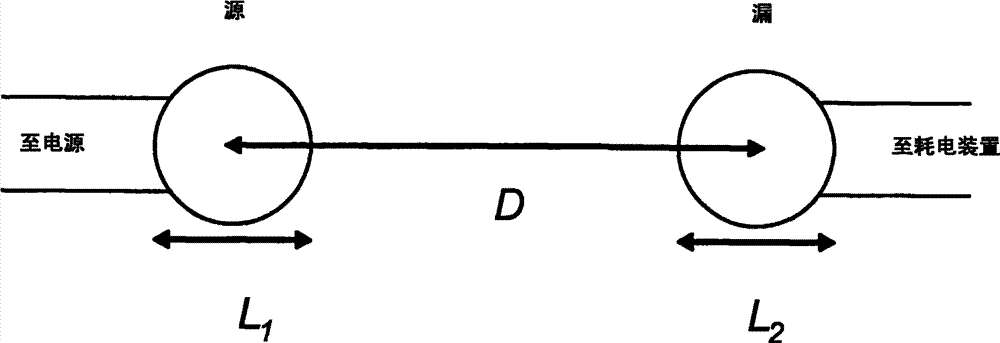
图1示出了总体上描述本发明一个实施例的示意图,其中在两个谐振物体之间无线传输能量。Figure 1 shows a schematic diagram generally describing an embodiment of the invention in which energy is wirelessly transferred between two resonant objects.
参考图1,通过距离D在具有特征尺寸L1的谐振源物体与具有特征尺寸L2的谐振装置物体之间传输能量。两个物体都是谐振物体。源物体连接到电源(未示出),装置物体连接到耗电装置(例如负载电阻器,未示出)。能量由电源提供给源物体,能量从源物体以无线非辐射方式传输到装置物体,并由耗电装置消耗。利用两个谐振物体的系统的场(例如电磁场或声场)进行无线非辐射能量传输。为了简单起见,在下文中我们将假设场为电磁场。Referring to FIG. 1 , energy is transferred over a distance D between a resonant source object with a characteristic dimension L1 and a resonant device object with a characteristic dimension L2 . Both objects are resonant objects. The source object is connected to a power source (not shown) and the device object is connected to a power consuming device (eg a load resistor, not shown). Energy is provided to the source object by the power supply, and the energy is transmitted from the source object to the device object in a wireless and non-radiative manner, and is consumed by the power consumption device. Wireless non-radiative energy transfer utilizing the fields (such as electromagnetic or acoustic fields) of a system of two resonant objects. For simplicity, in the following we will assume that the field is an electromagnetic field.
应当理解,尽管图1的实施例示出了两个谐振物体,但是在下面的很多实例中,其他实施例可以以3个或更多个谐振物体为特征。例如,在一些实施例中,单个源物体能够向多个装置物体传输能量。在一些实施例中,可以将能量从第一装置传输到第二装置,然后从第二装置传输到第三装置,依次类推。It should be understood that while the embodiment of FIG. 1 shows two resonant objects, other embodiments may feature 3 or more resonant objects in many of the examples below. For example, in some embodiments, a single source object can transmit energy to multiple device objects. In some embodiments, energy may be transferred from a first device to a second device, then from the second device to a third device, and so on.
首先,我们给出理论框架以便于理解非辐射方式的无线能量传输。不过注意,应当理解本发明的范围不限于理论。First, we give a theoretical framework to understand non-radiative wireless energy transfer. Note, however, that it should be understood that the scope of the invention is not limited by theory.
耦合模理论coupled mode theory
用于对两个谐振物体1和2之间的谐振能量交换进行建模的适当分析框架是“耦合模理论”(coupled-mode theory,CMT)的框架。例如,参见Haus,H.A.Waves and Fields in Optoelectronics(Prentice-Hall,新泽西,1984)。两个谐振物体1和2的系统的场近似于F(r,t)≈a1(t)F1(r)+a2(t)F2(r),其中F1,2(r)是1和2各自的归一化到单位能量的本征模式(eigenmode),并且限定场幅度a1,2(t),使得|a1,2(t)|2分别等于物体1和2之内存储的能量。然后,可以示出在最低阶上场幅度满足:A suitable analytical framework for modeling the resonant energy exchange between two
(1)(1)
其中ω1,2是本征模式的个体本征频率,Γ1,2是由于物体的固有(吸收、辐射等)损耗导致的谐振宽度,κ是耦合系数。方程(1)表明,在严格谐振(ω1=ω2且Γ1=Γ2)时,组合系统的本征模式被2κ拆分;两物体之间的能量交换在时间π/κ之内发生且除了损耗之外,该能量交换几乎是完美的,在耦合速率比全部的损耗速率快得多时(κ>>Γ1,2),损耗最小。耦合损耗比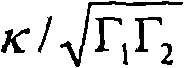
在一些实施例中,能量传输应用优选使用对应于低(慢)固有损耗速率Γ的高Q=ω/2Γ的谐振模式。在使用渐逝(无损耗)稳定近场,而不是有损耗辐射远场来实现耦合的情况下,可以满足这个条件。In some embodiments, energy transfer applications preferably use resonant modes of high Q=ω/2Γ corresponding to low (slow) intrinsic loss rates Γ. This condition is satisfied in cases where coupling is achieved using an evanescent (lossless) stable near-field, rather than a lossy radiating far-field.
为了实现能量传输方案,通常,有限大小的物体是更适合的,即在拓扑上各处被空气围绕的物体是更适合的。令人遗憾的是,有限范围的物体不能够支持在空气中各个方向上按照指数衰减的电磁状态,这是因为从自由空间中的麦克斯韦方程可知:
此外,在一些实施例中,在大于物体特征尺寸的距离上,对应于强(即快)耦合速率κ的小Qκ=ω/2κ是优选的。因此,由于通常由波长来设置近场扩展到有限大小谐振物体周围区域中的程度,因此在一些实施例中,可以利用亚波长大小的谐振物体来实现这种中距离非辐射耦合,从而实现显著更长的渐逝场尾部。从稍后的实例中将会看到,这种亚波长谐振常常会伴有高Q值,因此对于可能移动的谐振装置-物体而言,这通常将是适当的选择。尽管如此,注意,在一些实施例中,谐振源物体将是固定不动的,这样,谐振源物体在其允许的几何形状和尺寸方面受限较少,因此可以选择足够大的几何形状和尺寸,使得近场范围不受波长限制。如果调谐得靠近截止频率,那么广度接近无穷大的物体(例如电介质波导)能够支持渐逝尾部沿远离物体的方向按照指数缓慢衰减的导模(guided mode),因此其能够具有几乎无穷大的Q。Furthermore, in some embodiments a small Q κ = ω/2κ corresponding to a strong (ie fast) coupling rate κ is preferred over distances larger than the object's characteristic size. Thus, since the extent to which the near-field extends into the region around a finite-sized resonant object is typically set by the wavelength, in some embodiments, subwavelength-sized resonant objects can be utilized to achieve such mid-range non-radiative coupling, enabling significant Longer evanescent field tail. As will be seen later in the examples, such sub-wavelength resonances are often accompanied by high Q values, so for resonant device-objects that may move, this will usually be the appropriate choice. Nevertheless, note that in some embodiments the resonant source object will be immobile, such that the resonant source object is less constrained in its allowable geometry and size, so a sufficiently large geometry and size can be chosen , making the near-field range independent of wavelength. Objects with near-infinite breadth, such as dielectric waveguides, can support guided modes with evanescent tails that decay exponentially slowly away from the object if tuned close to the cutoff frequency, and thus can have almost infinite Q.
在下文中,我们描述了若干种适于上述类型的能量传输的系统实例。我们将展示如何计算上述CMT参数ω1,2、Q1,2和Qκ,以及如何选择用于特定实施例的这些参数,以便产生期望的品质因数
自谐振导线线圈Self Resonant Wire Coil
在一些实施例中,一个或多个谐振物体是自谐振导线环路。参考图2,将长度为l截面半径为a的导线盘绕成由空气包围的半径为r高度为h(即,匝数为
谐振的本质在于能量从线圈电容之内的电场周期性地变换到自由空间中的磁场,电场是由于整个线圈上的电荷分布ρ(x)造成的,磁场是由于导线中的电流分布j(x)造成的。具体而言,电荷守恒方程
其中μ0和ε0是自由空间的磁导率和介电常数。利用这些定义,分别由通用公式
这种谐振系统中的损耗由导线之中的欧姆(材料吸收)损耗和进入自由空间的辐射损耗构成。可以再次分别利用吸收或辐射的功率量来定义总吸收电阻Rabs和总辐射电阻Rrad:Losses in such a resonant system consist of ohmic (material absorption) losses in the wire and radiation losses into free space. The total absorption resistance R abs and the total radiation resistance R rad can again be defined in terms of the amount of power absorbed or radiated, respectively:
其中
从方程(2)-(5)得出,要确定谐振参数,仅需要知道谐振线圈中的电流分布j。解麦克斯韦方程以精确找到导线线圈的谐振电磁本征模式的电流分布比解例如标准LC电路的电流分布更棘手,在文献中我们没有找到任何有限长度线圈的精确解,这使得精确解难以得到。原则上,可以写出精细的类似传输线的模型,并通过硬算求解。相反,我们给出了与试验吻合很好(~5%)的模型(如下所述)。注意:形成每个线圈的有限尺度的导体施加的边界条件是电流在线圈末端必需为零,这是因为没有电流能够离开导线,我们假设用沿导线长度分布的正弦电流分布很好地近似每个线圈的谐振模式。我们对最低阶模式感兴趣,因此,如果用x表示沿着导体的坐标,使其从-l/2延伸到+l/2,那么电流幅度曲线将具有I(x)=Iocos(πx/l)的形式,其中我们已经假定对于特定的x处电流不会沿着导线周长显著变化,如果a<<r,那么这是能成立的假设。从电荷的连续性方程立刻得到,线电荷密度曲线应该具有ρ(x)=ρosin(πx/l)的形式,于是
在表1中给出了具有λS/r≥70(即,非常适用于近场耦合且完全在准静态极限之内的谐振线圈)的亚波长模式的谐振线圈的两个特定实施例的结果。针对亚波长线圈谐振模式的两种不同情形,示出了波长和吸收、辐射和总损耗速率的数值结果。注意,使用了导电材料铜(σ=5.998·10^-7S/m)。可以看出,在微波频率处预计的品质因数为QS abs≥1000和QS rad≥5000。Results for two specific embodiments of resonant coils with subwavelength modes of λS /r ≥ 70 (i.e., resonant coils well suited for near-field coupling and well within the quasi-static limit) are given in Table 1 . Numerical results are shown for wavelength and absorption, radiation and total loss rates for two different cases of subwavelength coil resonant modes. Note that copper (σ = 5.998·10^-7 S/m) is used as a conductive material. It can be seen that Q S abs ≥ 1000 and Q S rad ≥ 5000 are expected at microwave frequencies.
表1Table 1
参考图3,在一些实施例中,在两个自谐振导线线圈之间传输能量。使用磁场来耦合其中心之间距离为D的不同谐振导线线圈。通常,对于h<r的线圈而言,可以在所考虑的系统中实现有利于磁耦合的电耦合约束。然后,分别将两个线圈1,2的电流分布、峰值电流和感应系数定义为j1,2(x)、I1,2和L1,2,它们是单线圈情形的j(x)、I0和L的类似量,因此它们是明确的,我们能够通过总能量来定义它们的互感:Referring to Figure 3, in some embodiments, energy is transferred between two self-resonant wire coils. A magnetic field is used to couple different resonant wire coils with a distance D between their centers. In general, for coils with h<r, an electrical coupling constraint that favors magnetic coupling can be achieved in the considered system. Then, the current distribution, peak current and inductance of the two
其中,积分内的阻滞因数~exp(iωD/c)已经在感兴趣的准静态状态D<<λ下被忽略了,其中每个线圈位于另一个线圈的近场之内。利用这一定义且假定没有电耦合,则耦合系数由
因此,为了计算两个自谐振线圈之间的耦合速率,再次需要电流分布曲线,并且再次利用假设的正弦电流分布曲线,我们通过方程(6)以数值方式计算其中心之间距离为D的两个自谐振线圈之间的互感MS,从而也确定了Qκ,S。Therefore, to calculate the coupling rate between two self-resonant coils, the current profile is again required, and again using the assumed sinusoidal current profile, we numerically calculate the two coils with a distance D between their centers via equation (6). The mutual inductance M S between the self-resonant coils, thus also determines the Q κ,S .
表2Table 2
参考表2,示出了以成对自谐振线圈或相同的自谐振线圈为特征的示例性实施例的相关参数。针对两个简正模式的平均波长和损耗速率,给出了数值结果(未示出个别值),而且针对表1中呈现的两种情况的模式给出了作为耦合距离D的函数的耦合速率和品质因数。可以看出,对于中等距离D/r=10-3,预计的耦合损耗比在κ/Γ~2-70的范围内。Referring to Table 2, relevant parameters for exemplary embodiments featuring pairs of self-resonant coils or identical self-resonant coils are shown. Numerical results (individual values not shown) are given for the average wavelength and loss rate of the two normal modes, and the coupling rate as a function of the coupling distance D is given for the modes of the two cases presented in Table 1 and quality factor. It can be seen that for an intermediate distance D/r = 10-3, the expected coupling loss ratio is in the range of κ/Γ ~ 2-70.
带电容负载的导线线圈Wire coil with capacitive load
在一些实施例中,一个或多个谐振物体是带电容负载的导线线圈。参考图4,将如上所述的具有N匝导线的螺旋线圈连接到一对面积为A的平行导电板,该对平行导电板经由相对介电常数为ε的电介质而间隔开了距离d,并且每个部分都被空气围绕(如图所示,N=1,h=0)。该板具有电容Cp=εoεA/d,该电容被加到线圈的分布电容上,从而改变了其谐振。然而,应当注意,负载电容器的存在显著改变了导线内部的电流分布,并由此线圈的总有效电感L和总有效电容C分别与LS和CS不同,LS和CS是利用正弦电流分布曲线针对相同几何形状的自谐振线圈计算出的。由于在外部负载电容器的板上积累了一些电荷,因此减少了导线内部的电荷分布ρ,使得C<CS,于是,从电荷守恒方程得到,电流分布j变得平坦,因此L>LS。这个系统的谐振频率为
通常,可以为该系统找到期望的CMT参数,但这再次需要麦克斯韦方程的非常复杂的解。相反,我们将仅仅分析特殊情形,在这种特殊情形下,可以对电流分布做出合理的猜测。当Cp>>Cs>C时,那么
外部负载电容Cp为调谐谐振频率提供了自由(例如通过调谐A或d)。然后,对于特别简单的情况h=0(对于这种情况我们有解析公式),在最优频率ω*下,总Q=ωL/(Rabs+Rrad)变得最高,达到值Q*。The external load capacitance Cp provides freedom to tune the resonant frequency (eg by tuning A or d). Then, for the particularly simple case h=0 (for which we have analytical formulas), at the optimal frequency ω * , the total Q=ωL/(R abs +R rad ) becomes highest, reaching the value Q * .
在较低频率下,它受欧姆损耗支配,而在较高频率下,它受辐射支配。然而,应当注意:只要ω*<<ωS,这些公式都是精确的,并且如上所述,在N=1时这几乎始终成立,当N>1,这通常不太精确,原因在于h=0通常意味着大的固有电容。如果需要相对于外部电容减小固有电容,则可以使用具有大h的线圈,不过这时L和ω*、Q*的公式再次不太精确了。预计会有类似的定性行为,但在这种情况下要做出定量预测需要更复杂的理论模型。At lower frequencies it is dominated by ohmic losses, while at higher frequencies it is dominated by radiation. However, it should be noted that these formulas are exact as long as ω * << ω S , and as mentioned above, this is almost always true for N=1, when N>1 this is usually less accurate because h= 0 usually means large intrinsic capacitance. If it is desired to reduce the intrinsic capacitance relative to the external capacitance, a coil with a large h can be used, but then again the formulas for L and ω * , Q * are less accurate. Similar qualitative behavior is expected, but making quantitative predictions in this case requires more sophisticated theoretical models.
在表3中给出了在最佳频率方程(7)下针对N=1且h=0的线圈的λ/r≥70(即非常适于近场耦合并完全在准静态极限之内)的亚波长模式的两个实施例的上述分析的结果。为了确认恒流假设和所得解析公式的有效性,还利用另一种完全独立的方法来进行模式求解计算(mode-solving calculation):计算的3D有限元频域(FEFD)模拟被进行(严格独立于空间离散化,在频域中解麦克斯韦方程,例如参见Balanis,C.A.Antenna Theory:Analysis andDesign(Wiley,新泽西,2005年)),其中利用复数阻抗边界条件
表3table 3
参考图5,在一些实施例中,在两个本身带电容负载的线圈之间传输能量。对于中心之间的距离为D的两个带电容负载的线圈1和2之间的能量传输速率而言,在ω<<ωS的情况下,可以通过利用恒流分布并使用方程(6)以数值方式计算互感M。在h=0且N1、N2是整数的情况下,我们再次有了解析公式,在准静态极限r<<D<<λ且对于图4所示的相对取向而言,该解析公式是M≈π/2·μo(r1r2)2N1N2/D3,这意味着
对于N1=N2=1而言这再次是更加精确的。This is again more accurate for N 1 =N 2 =1.
从方程(9)可以看出,品质因数得到最大化的最佳频率是使得
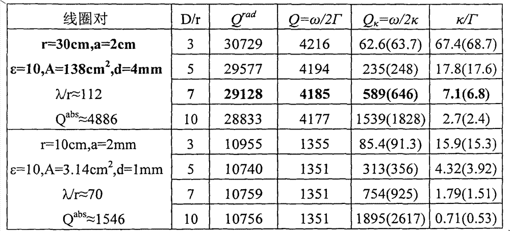
参考表4,针对均由表3所述的一对匹配的负载线圈(loaded coil)所构成的两个系统,示出了基于以上说明得到的数值FEFD和(括号中的)解析结果。针对这两种情况示出了平均波长和损耗速率、以及作为耦合距离D的函数的耦合速率和耦合损耗比品质因数κ/Γ。注意,示出的平均数值Γrad再次与图3的单环路值稍微不同,未示出Γrad的解析结果,但使用了单环路值。(在表中用黑体突出了对应于图5中的图的特定参数。)再次选择N=1以使恒流假设是一个好的假设,并通过方程(6)以数值方式计算M。确实,可以通过与计算的FEFD模式求解模拟吻合来确认精确度,后者通过组合系统的两个简正模式的频率分隔距离(frequency splitting)(=2κ)来给出κ。结果表明,对于中等距离D/r=10-3,预计的耦合损耗比在κ/Γ~0.5-50的范围内。Referring to Table 4, the numerical FEFD and (in parentheses) analytical results obtained based on the above description are shown for two systems each composed of a matched pair of loaded coils as described in Table 3. The average wavelength and loss rate, as well as the coupling rate and coupling loss ratio figure of merit κ/Γ as a function of coupling distance D are shown for both cases. Note that the average value Γ rad shown is again slightly different from the single loop value of Figure 3, the analytical results for Γ rad are not shown, but the single loop value is used. (Specific parameters corresponding to the plots in Figure 5 are highlighted in bold in the table.) Again N=1 is chosen so that the constant current assumption is a good assumption, and M is calculated numerically by equation (6). Indeed, the accuracy can be confirmed by the simulated fit with the calculated FEFD mode solution, which gives κ by the frequency splitting (=2κ) of the two normal modes of the combined system. The results show that for intermediate distances D/r = 10-3, the predicted coupling loss ratios are in the range of κ/Γ ~ 0.5-50.
表4Table 4
在一些实施例中,可以利用以上结果来对采用带电容负载的线圈的无线能量传输系统的性能进行改善或优化。例如,利用不同的系统参数估算方程(10),可以看出为了使系统品质因数κ/Γ最大化,我们例如能够:In some embodiments, the above results can be used to improve or optimize the performance of wireless energy transfer systems employing capacitively loaded coils. For example, using different system parameter estimation equations (10), it can be seen that in order to maximize the system figure of merit κ/Γ, we can for example:
--减小导电材料的电阻率。例如,可以利用良导体(例如铜或银)和/或降低温度来实现这一目的。在非常低的温度下,也可以使用超导材料来获得极好的性能。--Reduce the resistivity of conductive materials. For example, good conductors such as copper or silver and/or reduced temperature can be used to achieve this. At very low temperatures, superconducting materials can also be used to achieve excellent performance.
--增加导线半径a。在典型实施例中,该动作受到物理尺寸因素的限制。--Increase the wire radius a. In typical embodiments, this motion is limited by physical size factors.
--对于固定的期望距离D的能量传输而言,增大环路的半径r。在典型实施例中,该动作受到物理尺寸因素的限制。- For a fixed desired distance D of energy transfer, increase the radius r of the loop. In typical embodiments, this motion is limited by physical size factors.
--对于固定的期望距离与环路尺寸比D/r而言,减小环路的半径r。在典型实施例中,这种动作受到物理尺寸因素的限制。- For a fixed desired distance to loop size ratio D/r, reduce the radius r of the loop. In typical embodiments, such motion is limited by physical size factors.
--增加匝数N。(尽管预计在N>1的情况下方程(10)不太精确,但定性地看,它仍然提供了一个好的指标,即我们预期利用增大的N来改善耦合损耗比。)在典型实施例中,该动作受到物理尺寸因素和可能的电压因素的限制,如在后续部分中将要讨论的那样。-- Increase the number of turns N. (Although equation (10) is expected to be less precise for N > 1, it still provides, qualitatively, a good indication that we expect to improve the coupling-loss ratio with increasing N.) In a typical implementation In this case, the action is limited by physical size factors and possibly voltage factors, as will be discussed in subsequent sections.
--调节两个线圈之间的对准和取向。在两个圆柱形线圈均具有严格相同的圆柱对称轴时(即它们彼此“面对”时),品质因数得到优化。在一些实施例中,应当避免导致零互感的线圈间特定的相互角度和取向(例如两个线圈的轴垂直的取向)。--Adjust the alignment and orientation between the two coils. The figure of merit is optimized when both cylindrical coils have exactly the same axis of cylindrical symmetry (ie when they "face" each other). In some embodiments, certain mutual angles and orientations between the coils that result in zero mutual inductance should be avoided (eg, an orientation where the axes of the two coils are perpendicular).
最后,注意,在典型实施例中,线圈高度h不应当影响到耦合损耗比,这是因为它主要影响在Q和Qκ之间消除的线圈电感。但仍可以使用它来减小线圈的固有电容,以有利于外部负载电容。Finally, note that in typical embodiments, the coil height h should not affect the coupling loss ratio since it mainly affects the coil inductance canceled between Q and Q κ . But it can still be used to reduce the inherent capacitance of the coil in favor of the external load capacitance.
可以使用上述的分析方法来设计具有期望参数的系统。例如,如下文所列示的,在材料为铜(σ=5.998·107S/m)的情况下,在将两个相同的给定半径的单匝线圈设计成系统以在它们之间针对给定的D/r来实现在κ/Γ方面的特定性能时,可以使用上述技术来确定应当使用的导线截面半径。The analysis methods described above can be used to design a system with desired parameters. For example, as listed below, in the case of copper (σ=5.998·10 7 S/m) as the material, when two identical single-turn coils of a given radius are designed as a system for The technique described above can be used to determine the wire section radius that should be used for a given D/r to achieve a specific performance in terms of κ/Γ.
D/γ=5,κ/Γ≥10,
D/γ=5,κ/Γ≥10,
D/γ=5,κ/Γ≥20,
D/γ=5,κ/Γ≥20,
D/γ=10,κ/Γ≥1,
D/γ=10,κ/Γ≥1,
D/γ=10,κ/Γ≥3,
D/γ=10,κ/Γ≥3,
对于两个不相似环路的情形可以进行类似的分析。例如,在一些实施例中,所考虑的装置是非常具体的(例如膝上型电脑或手机),因此装置物体的尺寸(rd,hd,ad,Nd)非常受限。然而,在一些这样的实施例中,对源物体的约束(rs,hs,as,Ns)要少得多,这是因为可以将源例如放在地板下或顶棚上。在这种情况下,根据应用,期望的距离常常是明确的(例如对于从地板以无线方式为桌上的膝上型电脑充电,D~1m)。下面列出的是在材料同样为铜(σ=5.998·107S/m)的情况下如何改变源物体的尺寸以在方面实现期望的系统性能的实例(简化到NS=Nd=1且hs=hd=0的情形)。A similar analysis can be performed for the case of two dissimilar loops. For example, in some embodiments the device under consideration is very specific (eg a laptop or a cell phone) and thus the dimensions (rd , hd , ad , Nd ) of the device object are very constrained. However, in some such embodiments, there are far fewer constraints ( rs , hs , as , Ns ) on the source object, since the source can be placed, for example, under a floor or on a ceiling. In this case, depending on the application, the desired distance is often well-defined (eg D ~ lm for wirelessly charging a laptop on a table from the floor). Listed below is how to change the size of the source object in the case that the material is also copper (σ=5.998·10 7 S/m) An example of achieving the desired system performance (simplified to the case where Ns = Nd = 1 and hs = hd = 0).
如下文所述,在一些实施例中,外部扰动限制了谐振物体的品质因数Q,并由此改变线圈参数不能获得Q的改善。在这样的情况下,可以选择通过减小Qκ(即增大耦合)来提高耦合损耗比品质因数。耦合不取决于频率和匝数,并且耦合非常微弱地依赖于线圈高度。因此,剩余的自由度是:As described below, in some embodiments, external perturbations limit the quality factor Q of the resonant object, and thus no improvement in Q can be achieved by changing the coil parameters. In such cases, one may choose to increase the coupling loss ratio figure of merit by reducing Qκ (ie, increasing coupling). Coupling does not depend on frequency and number of turns, and coupling depends very weakly on coil height. Therefore, the remaining degrees of freedom are:
--增大导线半径a1和a2。在典型实施例中,这种动作受到物理尺寸因素的限制。-- Increase the wire radius a 1 and a 2 . In typical embodiments, such motion is limited by physical size factors.
--对于固定的期望距离D的能量传输,增大线圈半径r1和r2。在典型实施例中,这种动作受到物理尺寸因素的限制。- For energy transmission for a fixed desired distance D, increase the coil radii r 1 and r 2 . In typical embodiments, such motion is limited by physical size factors.
--对于固定的期望距离与线圈尺寸比
--调节两个线圈之间的对准和取向。在典型实施例中,在两个圆柱形线圈都具有严格相同的圆柱对称轴时(即它们彼此“面对”),耦合得到优化。显然应当避免导致零互感的线圈间特定的相互角度和取向(例如两个线圈的轴垂直的取向)。--Adjust the alignment and orientation between the two coils. In a typical embodiment, the coupling is optimized when both cylindrical coils have exactly the same cylindrical axis of symmetry (ie they "face" each other). Certain mutual angles and orientations between the coils which result in zero mutual inductance should obviously be avoided (for example an orientation in which the axes of the two coils are perpendicular).
下面将详细讨论除效率之外的其他实际因素,例如物理尺寸限制。Practical factors other than efficiency, such as physical size limitations, are discussed in detail below.
注意,尽管上文给出并分析了特定实施例(自谐振线圈和带电容负载的线圈)来作为将谐振磁耦合用于无线能量传输的系统实例,即自谐振导线线圈和带电容负载的谐振导线线圈的系统实例,但可以借助磁耦合将支持其磁能延伸得比其电能远得多的电磁模式的任何系统用于传输能量。例如,对于支持期望种类的磁谐振的分布电容和电感而言,可以有很多抽象的几何性质。在这些几何性质的任一个中,能够选择特定参数来增大和/或优化
认识到上述谐振耦合感应方案与公知的用于能量传输的非谐振感应方案之间的差异也是重要的。利用CMT容易证明,将几何性质和源处存储的能量保持固定,谐振感应机制比常规的非谐振机制能提供多~Q2(~106)倍的功率用于在装置处工作。这就是为什么利用后者仅可能进行封闭范围无接触中等功率(~W)传输,而利用谐振却允许进行封闭范围但大功率(~kW)传输的原因,或者,如当前提出的,如果还确保工作在强耦合状态下,则中等范围、中等功率的传输是可能的。当前将带电容负载的导线环路用作谐振天线(例如在手机中),但那些环路工作在远场状态下,D/r>>1,r/λ~1,且人为将辐射Q设计得小,以使天线高效,因此它们不适于能量传输。It is also important to recognize the difference between the resonant coupled induction scheme described above and known non-resonant inductive schemes for energy transfer. It is easy to demonstrate using CMT that, keeping the geometry and energy stored at the source fixed, the resonant induction mechanism can deliver ~ Q2 (~ 106 ) times more power for operation at the device than conventional non-resonant mechanisms. This is why closed-range contactless medium power (~W) transmission is only possible with the latter, while closed-range but high-power (~kW) transmission is possible with resonance, or, as currently proposed, if also ensuring Working in a strong coupling state, medium-range, medium-power transmission is possible. Wire loops with capacitive loads are currently used as resonant antennas (e.g. in mobile phones), but those loops operate in the far-field regime, D/r>>1, r/λ~1, and the radiation Q is artificially designed must be small for the antennas to be efficient, so they are not suitable for energy transfer.
在一些实施例中,电场和磁场都可以用于无线能量传输。如图6所示,考虑被空气围绕的半径为r且相对介电常数为ε的二维电介质盘物体,其支持高Q的“回音廊”谐振模式。这种谐振系统之内存储的能量的损耗机制是向自由空间中的辐射和盘材料内部的吸收。在电介质介电常数ε大且方位角场变化慢时(即主数m小),可以实现高Qrad且长拖尾的亚波长谐振。材料吸收与材料损耗正切相关:Qabs~Re{ε}/Im{ε}。利用两种独立的方法对这种盘谐振进行模式求解计算:数值方式,利用30pts/r的分辨率执行2D有限差分频域(FDFD)模拟(严格独立于空间离散化在频域中解麦克斯韦方程);解析方式,使用极坐标中的变量(SV)的标准分离(standard separation)。In some embodiments, both electric and magnetic fields can be used for wireless energy transfer. As shown in Fig. 6, consider a two-dimensional dielectric disk object of radius r and relative permittivity ε surrounded by air, which supports a high-Q "whispering gallery" resonant mode. The loss mechanisms of the energy stored within this resonant system are radiation into free space and absorption within the disk material. When the dielectric permittivity ε is large and the azimuthal field changes slowly (that is, the principal number m is small), subwavelength resonance with high Q rad and long tail can be realized. Material absorption is tangentially related to material loss: Q abs ~Re{ε}/Im{ε}. Mode-solving calculations of this disk resonance were performed using two independent methods: numerically, performing 2D finite-difference frequency-domain (FDFD) simulations with a resolution of 30pts/r (solution of Maxwell's equations in the frequency domain strictly independent of spatial discretization ); analytically, using the standard separation of variables (SV) in polar coordinates.
表5table 5
在表5中给出了λ/r≥10的两种TE极化电介质盘亚波长模式的结果。表5针对两种不同情况的亚波长盘谐振模式示出了波长和吸收、辐射和总损耗速率的数值FDFD(括号中为解析式SV)结果。注意,使用了盘材料损耗正切Im{ε}/Re{ε}=10-4。(在表中用黑体突出了与图6中的图相对应的特定参数。)两种方法吻合得极好,并且两种方法暗示了:对于适当设计的谐振低损耗电介质物体,可以实现Qrad≥2000和Qabs~10000的值。注意,对于3D情形,计算的复杂性会大大增加,而物理过程不会有显著不同。例如,ε=147.7的球形物体具有m=2、Qrad=13962且λ/r=17的回音廊模式。In Table 5 the results for two TE polarized dielectric disk subwavelength modes with λ/r≥10 are given. Table 5 shows the numerical FDFD (analytic SV in parentheses) results for wavelength and absorption, radiation and total loss rates for two different cases of subwavelength disk resonance modes. Note that the disk material loss tangent Im{ε}/Re{ε}=10 -4 is used. (Specific parameters corresponding to the graph in Figure 6 are highlighted in bold in the table.) Both methods agree extremely well, and both methods imply that for a properly designed resonant low-loss dielectric object, Q rad can be achieved Values > 2000 and Q abs ~ 10000. Note that for the 3D case, the computational complexity increases considerably, while the physical process does not differ significantly. For example, a spherical object with ε = 147.7 has a whispering gallery mode with m = 2, Q rad = 13962 and λ/r = 17.
表5中示出的待定值ε可能一开始看起来不现实地大。然而,不仅在微波范围中(适于大约米范围的耦合应用)有很多材料既有适当足够高的介电常数和低损耗(例如二氧化钛、四钛化钡(Barium tetratitanatem)、钽酸锂等),而且ε可以代为表示其他已知亚波长表面波系统的有效指标,例如金属状(负ε)材料或金属-电介质光子晶体的表面上的表面等离子体振子模式(surface-plasmon mode)。The pending value ε shown in Table 5 may at first appear to be unrealistically large. However, not only in the microwave range (suitable for coupling applications in the order of meters) there are many materials with a suitably high enough dielectric constant and low loss (e.g. titanium dioxide, Barium tetratitanatem, lithium tantalate, etc.) , and ε can be used instead as an effective indicator for other known subwavelength surface wave systems, such as surface-plasmon modes on the surface of metallic-like (negative ε) materials or metal-dielectric photonic crystals.
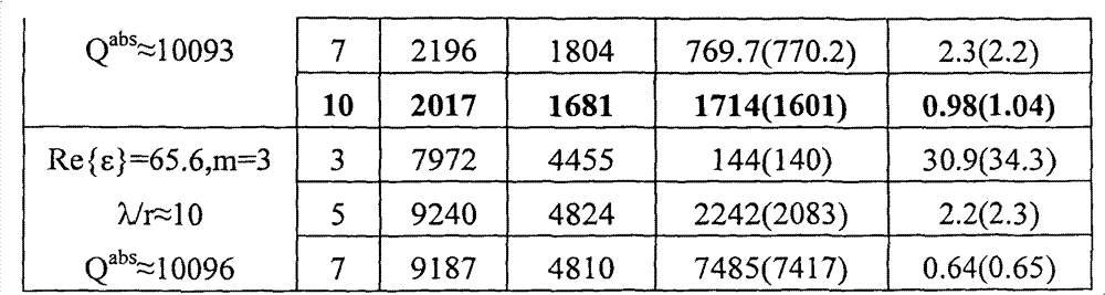
现在为了计算两个盘1和2之间能量传输的可实现速率,如图7所示,我们将盘1和2放置成它们的中心之间的距离为D。按照数值方式,FDFD模式求解器模拟通过组合系统的简正模式的频率分隔距离(=2κ)来给出κ,这是初始单个盘模式的偶和奇叠加;按照解析方式,利用变量分离的表达式,本征场E1,2(r)CMT通过
表6Table 6
对无关物体的系统灵敏度System sensitivity to extraneous objects
通常,基于谐振的无线能量传输方案的特定实施例的总体性能极大地取决于谐振物体谐振的鲁棒性。因此,希望分析谐振物体对附近存在的随机非谐振无关物体的灵敏度。一种适当的分析模型是“微扰理论”(perturbation theory,PT)的分析模型,这种分析模型表明在存在无关物体e时,谐振物体1内部的场幅度a1(t)在一阶水平上满足:In general, the overall performance of a particular embodiment of a resonance-based wireless energy transfer scheme greatly depends on the robustness of the resonance of the resonant object. Therefore, it is desirable to analyze the sensitivity of a resonant object to the presence of random non-resonant unrelated objects nearby. An appropriate analytical model is the analytical model of "perturbation theory" (PT), which shows that in the presence of an unrelated object e, the field amplitude a 1 (t) inside the
其中,同样ω1是频率,Γ1是内在(吸收、辐射等)损耗速率,而κ11-e是由于e的存在而在1上诱发的频移,Γ1-e是由于e(e内部的吸收、来自e的散射等)造成的外在损耗速率。一阶PT模型仅对于小的扰动成立。尽管如此,如果将a1取为严格被扰模式(perturbed mode)的幅度,即使在该状态之外,参数κ11-e、Γ1-e也是明确的。还要注意,初始谐振物体模式的辐射场与无关物体的散射场之间的干涉效应对于强散射(例如金属物体的散射)来说能够导致全辐射——小于初始辐射Γ1的Γ1-e(即Γ1-e为负的)。where , again ω 1 is the frequency, Γ 1 is the intrinsic (absorption, radiation, etc. ) The extrinsic loss rate due to absorption by , scattering from e, etc.). The first-order PT model holds only for small disturbances. Nevertheless, if a 1 is taken as the amplitude of strictly perturbed mode, the parameters κ 11-e , Γ 1-e are clear even outside this state. Also note that the interference effect between the radiation field of the initially resonant object mode and the scattering field of an unrelated object can lead to a total radiation for strong scattering (such as that of a metallic object) - Γ 1-e smaller than the initial radiation Γ 1 (ie Γ 1-e is negative).
频移是一个问题,可以通过向一个或多个谐振物体施加校正其频率的反馈机制来“解决”该问题。例如,参考图8a,在一些实施例中,为每个谐振物体提供固定频率的振荡器和用于确定物体频率的监测器。振荡器和监测器都耦合到频率调节器,频率调节器能够通过例如调节物体的几何性质(例如,自谐振线圈的高度、带电容负载的线圈的电容器极板间距、电介质盘的形状等)或改变谐振物体附近的非谐振物体的位置来调节谐振物体的频率。频率调节器确定固定频率和物体频率之间的差异并且采取动作使物体频率与固定频率对准。这种技术确保了即使在存在无关物体时所有谐振物体也都能工作在相同的固定频率。Frequency shift is a problem that can be "solved" by applying a feedback mechanism to one or more resonant objects that corrects their frequency. For example, referring to Figure 8a, in some embodiments, each resonant object is provided with a fixed frequency oscillator and a monitor for determining the frequency of the object. Both the oscillator and the monitor are coupled to a frequency adjuster, which can be adjusted by, for example, geometric properties of the object (e.g. height of self-resonant coil, spacing of capacitor plates for coils with capacitive load, shape of dielectric disk, etc.) or Changing the position of the non-resonant object near the resonant object adjusts the frequency of the resonant object. The frequency adjuster determines the difference between the fixed frequency and the object frequency and takes action to align the object frequency with the fixed frequency. This technique ensures that all resonant objects operate at the same fixed frequency even in the presence of extraneous objects.
作为另一个实例,参考图8b,在一些实施例中,在能量从源物体向装置物体传输期间,装置物体向负载提供能量,并且效率监测器对传输的效率进行测量。耦合到负载和效率监测器的频率调节器进行动作以调节物体的频率,从而使传输效率最大化。As another example, referring to Figure 8b, in some embodiments, during the transfer of energy from a source object to a device object, the device object provides energy to a load, and an efficiency monitor measures the efficiency of the transfer. A frequency regulator coupled to the load and efficiency monitor acts to adjust the frequency of the object to maximize transmission efficiency.
在各个实施例中,可以使用依赖于谐振物体之间的信息交换的其他频率调节方案。例如,可以监测源物体的频率并将其发送到装置物体,接着利用频率调节器使其与该频率同步,如上文所述的那样。在其他实施例中,可以将单个时钟的频率发送到多个装置,然后使每个装置与该频率同步。In various embodiments, other frequency tuning schemes that rely on information exchange between resonant objects may be used. For example, the frequency of the source object can be monitored and sent to the device object, which is then synchronized to that frequency using a frequency regulator, as described above. In other embodiments, the frequency of a single clock may be sent to multiple devices and each device then synchronized to that frequency.
与频移不同的是,外在损耗可能会对能量传输方案的功能不利,这是因为它难以补偿,因此应当对总损耗速率Γ1[e]=Γ1+Γ1-e(和对应的品质因数
如上所述,这一事实的极重要含意涉及到对人的安全考虑。人也是非磁性的,并且能够承受强磁场而不会有任何风险。典型的实例是用于医疗测试的磁共振成像(MRI)技术,在该实例中,将B~1T的磁场安全用在人身上。相反,典型实施例中为了向装置提供几瓦功率所需的近磁场仅为B~10-4T,这实际上相当于地球磁场的大小。如上所述,由于也没有强的近电场并且该非辐射方案产生的辐射是最小的,因此合理的是:预计我们提出的能量传输方法对于活体生物应当是安全的。As mentioned above, very important implications of this fact relate to human safety considerations. Humans are also non-magnetic and can withstand strong magnetic fields without any risk. A typical example is Magnetic Resonance Imaging (MRI) technology for medical testing, where a magnetic field of B~IT is safely used on a person. In contrast, the near magnetic field required in typical embodiments to deliver several watts of power to a device is only B~10 -4 T, which is practically equivalent to the magnitude of the Earth's magnetic field. As mentioned above, since there is also no strong near electric field and the radiation produced by this non-radiative scheme is minimal, it is reasonable to expect that our proposed energy transfer method should be safe for living organisms.
例如,可以对带电容负载的导线线圈的谐振系统已经最多部分地将磁能存储在其周围空间中的程度进行估计。如果忽略电容器的边缘电场,则线圈周围空间中的电能密度和磁能密度仅来自于由导线中的电流产生的电磁场;注意在远场中,这两个能量密度必然相等,对于辐射场而言始终是这种情况。通过使用由h=0[]的亚波长(r<<λ)电流环路(磁偶极子)产生的场的结果,我们能够根据距环路中心的距离p(在极限情况下r<<p)和相对于环路轴线的角度θ来计算电能密度与磁能密度之比:For example, it is possible to estimate the extent to which a resonant system of a capacitively loaded wire coil has at most partially stored magnetic energy in its surrounding space. If the fringing electric field of the capacitor is neglected, the electric and magnetic energy densities in the space around the coil come only from the electromagnetic field produced by the current in the wire; note that in the far field these two energy densities must be equal, always for the radiated field This is the case. By using the results of the field generated by a sub-wavelength (r<<λ) current loop (magnetic dipole) with h = 0[], we are able to use the distance p from the center of the loop (in the limit case r<< p) and the angle θ with respect to the loop axis to calculate the ratio of the electric energy density to the magnetic energy density:
(12)(12)
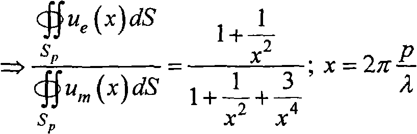
在上式中,第二行是通过求电能密度和磁能密度在半径为p的球面上的积分而得到的在所有角度上的平均值的比值。从方程(12)显然可以看出,确实对于近场(x<<1)中的所有角度,磁能密度都占支配优势,而在远场(x>>1)中,它们是相等的,如原本应当那样。而且,对环路进行优选布置,使得可能会干扰其谐振的物体靠近其轴线(θ=0),在那里没有电场。例如,使用表4中所述的系统,我们通过方程(12)能够评估,对于r=30cm的环路,在p=10r=3m距离处,平均电能密度与平均磁能密度之比将为~12%,在p=3r=90cm处,它将为1%,对于r=10cm的环路,在p=10r=1m距离处,该比值将为~33%,在p=3r=30cm处,它将为~2.5%。在更近距离处,该比值更小,从而在近场中,能量主要为磁能,而在辐射远场中,它们必定是具有相同数量级(比值→1),两者都非常小,这是因为场已经显著衰减了,原因在于带电容负载的线圈系统被设计成辐射非常小。因此,这是使这类谐振系统有资格作为磁谐振系统的标准。In the above formula, the second line is the ratio of the average values at all angles obtained by integrating the electric energy density and magnetic energy density on a spherical surface with radius p. It can be clearly seen from equation (12) that for all angles in the near field (x<<1), the magnetic energy density is dominant, and in the far field (x>>1), they are equal, as As it should be. Also, the loop is preferably arranged so that objects that might disturb its resonance are close to its axis (θ = 0), where there is no electric field. For example, using the system described in Table 4, we can evaluate by equation (12) that for a loop of r = 30 cm, at a distance of p = 10 r = 3 m, the ratio of the average electric energy density to the average magnetic energy density will be ~12 %, at p=3r=90cm, it will be 1%, for a loop of r=10cm, at p=10r=1m distance, the ratio will be ~33%, at p=3r=30cm, it will be ~2.5%. At closer distances the ratio is smaller, so that in the near field the energy is predominantly magnetic, while in the radiating far field they must be of the same order (ratio → 1), both very small because The field has been significantly attenuated because the capacitively loaded coil system is designed to radiate very little. Therefore, this is the criterion that qualifies this type of resonant system as a magnetic resonant system.
为了估计无关物体对包括电容器边缘电场的带电容负载的环路谐振的影响,我们使用先前所述的微扰理论公式
自谐振线圈比带电容负载的线圈更敏感,原因在于:对于前者,电场在空间中扩展的区域(整个线圈)比后者(仅在电容器内部)大得多。另一方面,自谐振线圈制造简单,并且能够抵抗比大多数集总电容器大得多的电压。Self-resonant coils are more sensitive than capacitively loaded coils because the area over which the electric field spreads in space (the entire coil) is much larger for the former than for the latter (only inside the capacitor). Self-resonant coils, on the other hand, are simple to manufacture and can withstand much higher voltages than most lumped capacitors.
通常,谐振系统的不同实施例对外部扰动具有不同的灵敏度,选择谐振系统取决于目前特定的应用以及对于该应用而言灵敏度或安全性有多么重要。例如,对于医疗可移植装置(例如无线供电的人工心脏)而言,必须使电场范围最小化到保护装置周围的组织的最高可能程度。在对外部物体的灵敏度或安全性很重要的情况下,应当设计谐振系统,使得在周围空间中的期望点(根据应用)的大部分处减小或最小化电能密度与磁能密度之比ue/um。In general, different embodiments of a resonant system have different sensitivities to external disturbances, and the choice of a resonant system depends on the particular application at hand and how important sensitivity or safety is to that application. For example, for medical implantable devices such as wirelessly powered artificial hearts, the extent of the electric field must be minimized to the highest possible degree to protect the tissue surrounding the device. Where sensitivity or safety to external objects is important, the resonant system should be designed such that the ratio u of the electrical energy density to the magnetic energy density is reduced or minimized at most of the desired points (depending on the application) in the surrounding space / um .
在使用主要不是磁场的谐振的实施例中,可能会担心无关物体的影响。例如,对于电介质盘而言,小的、低指数、低材料损耗或远处寄生物体将会诱发小的散射和吸收。在这种小扰动的情况下,可以分别利用解析式一阶微扰理论公式对这些外在损耗机制进行量化In embodiments that use resonance that is not primarily a magnetic field, there may be concerns about the influence of extraneous objects. For example, for a dielectric disk, small, low index, low material loss or distant parasites will induce little scattering and absorption. In the case of such small perturbations, these extrinsic loss mechanisms can be quantified separately using the analytical first-order perturbation theory formulation
其中,U=1/2∫d3rs(r)|E1(r)|2是无扰动模式的总谐振电磁能。可以看出,这些损耗都取决于无关物体处的谐振电场尾部E1的平方。相反,如上所述,从谐振物体1到另一个谐振物体2的耦合速率为
系统效率system efficiency
通常,任何能量传输方案的另一重要因素是传输效率。再次考虑在存在一组无关物体e的情况下谐振源s和装置d的组合系统。在以速率Γwork从装置汲取能量来用于工作时,可以确定这一基于谐振的能量传输方案的效率。装置场幅度的耦合模理论方程为In general, another important factor for any energy transfer scheme is transfer efficiency. Consider again the combined system of a resonant source s and device d in the presence of a set of unrelated objects e. The efficiency of this resonance-based energy transfer scheme can be determined when energy is drawn from the device for work at a rate Γ work . The coupled-mode theoretical equation of the field amplitude of the device is
其中
其中
参考图10,为了利用可更直接从特定谐振物体,例如带电容负载的导线环路获得的参数来重新导出和表达该公式(14),可以考虑系统的如下电路模型,其中电感Ls、Ld分别表示源环路和装置环路,Rs、Rd表示它们相应的损耗,Cs、Cd是要在频率ω处实现两个均谐振而需要的相应电容。考虑将电压发生器Vg连接到源且将工作(负载)电阻Rω连接到装置。互感由M表示。Referring to Fig. 10, to reformulate and express this equation (14) using parameters that can be obtained more directly from a specific resonant object, such as a wire loop with a capacitive load, the following circuit model of the system can be considered, where the inductance L s , L d represent the source loop and the device loop respectively, R s and R d represent their corresponding losses, C s and C d are the corresponding capacitances required to achieve both resonance at frequency ω. Consider connecting a voltage generator V g to the source and an operating (load) resistance R ω to the device. Mutual inductance is represented by M.
然后,从谐振的源电路(ωLs=1/ωCs)得到:Then, from the resonant source circuit (ωL s =1/ωC s ):
并从谐振的装置电路(ωLd=1/ωCd)得到:And from the resonant device circuit (ωL d =1/ωC d ):
因此,通过将第二项带入第一项中,得到:So, by substituting the second term into the first, we get:
现在我们取实部(时间平均的功率)来获得效率:Now we take the real part (time-averaged power) to get the efficiency:
即,
利用Γwork=Rw/2Ld,Γd=Rd/2Ld,Γs=Rs/2Ls以及
通过方程(14),我们可以发现,在选择的工作汲取率(work drainagerate)方面,在将工作汲取率选择为
例如,考虑在表4中描述的带电容负载的线圈实施例,耦合距离D/r=7,无关物体“人”与源的距离为Dh,且必须向负载提供Pwork=10W。那么,我们有(基于图11),在Dh~3cm处,
在很多情况下,谐振物体的尺寸将由当前的特定应用来设定。例如,当这种应用是向膝上型电脑或手机供电时,装置谐振物体的尺寸不能分别大于膝上型电脑或手机的尺寸。具体而言,对于具有指定尺寸的两个环路的系统而言,在环路半径rs,d和导线半径as,d方面,剩下的为了系统优化而能调节的独立参数是:匝数Ns,d、频率f和工作提取率(负载电阻)Γwork。In many cases, the size of the resonant object will be set by the particular application at hand. For example, when the application is powering a laptop or cell phone, the size of the device resonant object cannot be larger than the size of the laptop or cell phone, respectively. Specifically, for a system with two loops of specified size, in terms of loop radius r s,d and wire radius a s,d , the remaining independent parameters that can be tuned for system optimization are: turns Number N s, d , frequency f and work extraction rate (load resistance) Γ work .
通常,在各实施例中,我们想要增大或优化的主要因变量是总体效率ηwork。然而,在系统设计时,需要考虑其他重要变量。例如,在以带电容负载的线圈为特征的实施例中,设计可能受到例如导线内部流动的电流Is,d和电容器两端电压Vs,d的约束。这些限制可能是重要的,因为对于~瓦功率级别的应用来说,这些参数的值对于分别要采用的导线或电容器而言可能太大。此外,装置的总的负载Qtot=ωLd/(Rd+Rw)的量应当优选是小的,原因在于:为了匹配源和装置的谐振频率以使之处于其Q之内,当那些量非常大时,可能在试验上难度很大且对轻微偏差更敏感。最后,出于安全考虑,应当使辐射功率Prad,s,d最小,即便通常对于磁性非辐射方案,它们通常已经很小了。Generally, in various embodiments, the main dependent variable that we want to increase or optimize is the overall efficiency η work . However, there are other important variables to consider when designing a system. For example, in embodiments featuring capacitively loaded coils, the design may be constrained by, for example, the current I s,d flowing inside the wire and the voltage V s,d across the capacitor. These limitations may be important because for ~Watt power class applications the values of these parameters may be too large for the wires or capacitors respectively to be employed. Furthermore, the amount of total loading Q tot = ωL d /(R d + R w ) of the device should preferably be small because in order to match the resonant frequency of the source and the device to be within its Q, when those Very large quantities can be experimentally difficult and more sensitive to slight deviations. Finally, for safety reasons, the radiated powers P rad,s,d should be minimized even though they are usually already small for magnetically non-radiative solutions.
在下文中,我们接着研究每一自变量对因变量的影响。定义一个新变量wp,从而通过
增大Ns和Nd增大了
对于频率而言,同样,存在对效率来说最佳的一个频率,靠近该最佳频率,Qtot接近最大值。对于较低频率,电流变差(更大),但电压和辐射功率变好(更小)。通常,应当选择最佳频率或稍低的频率。For frequency, too, there is a frequency that is optimal for efficiency, near which Q tot approaches a maximum value. For lower frequencies, the current gets worse (more) but the voltage and radiated power get better (less). Usually, the best frequency or a slightly lower frequency should be chosen.
确定系统工作状态的一种方式是根据图解法。在图12中,对于rs=25cm、rd=15cm、hs=hd=0、as=ad=3mm且两者之间距离为D=2m的两个环路来说,在给定某种选择的wp和Ns的情况下,针对频率和Nd绘制了所有以上因变量(归一化到1瓦输出功率的电流、电压和辐射功率)。图中绘示了上述所有相关性。还可以做出因变量作为频率和wp两者的函数的等值线图,但Ns和Nd都是固定的。图13中针对相同的环路尺寸和距离示出了结果。例如,对于具有上面给出的尺寸的两个环路的系统而言,合理的参数选择是:Ns=2、Nd=6、f=10MHz且wp=10,这给出以下性能特性:ηwork=20.6%、Qtot=1264、Is=7.2A、Id=1.4A、Vs=2.55kV、Vd=2.30kV、Prad,s=0.15W、Prad,d=0.006W。注意,图12和13中的结果以及上面刚计算出的性能特性是利用上面给出的解析公式获得的,因此预计对于大的Ns、Nd值它们较不精确,但它们仍然会给出比例和数量级的良好估计。One way to determine the operating state of a system is based on a diagram. In Fig. 12, for two loops with rs = 25cm, rd = 15cm, h s = hd = 0, a s = ad = 3mm and the distance between them is D = 2m, at All the above dependent variables (current, voltage and radiated power normalized to 1 Watt output power) are plotted against frequency and Nd given some choice of wp and Ns . All of the above dependencies are plotted in the figure. It is also possible to make contour plots of the dependent variable as a function of both frequency and wp, but with both Ns and Nd fixed. The results are shown in Figure 13 for the same loop size and distance. For example, for a system with two loops of the dimensions given above, a reasonable choice of parameters is: Ns = 2, Nd = 6, f = 10 MHz and wp = 10, which gives the following performance characteristics: η work =20.6%, Q tot =1264, I s =7.2A, I d =1.4A, V s =2.55kV, V d =2.30kV, P rad,s =0.15W, P rad,d =0.006W . Note that the results in Figures 12 and 13 and the performance characteristics calculated just above were obtained using the analytical formulas given above, so they are expected to be less accurate for large values of N s , N d , but they still give Good estimates of scale and magnitude.
最后,还可以针对源的尺寸进行优化,因为如前所述,通常仅装置尺寸是受限的。即,可以将rs和as添加到自变量集合中,并针对所有有问题的因变量对这些也进行优化(先前仅看到如何针对效率这么做)。这种优化会获得改善的结果。Finally, it is also possible to optimize for the size of the source since, as mentioned earlier, usually only the size of the device is limited. That is, one can add r s and a s to the set of independent variables and optimize these also for all problematic dependent variables (previously only saw how to do this for efficiency). This optimization leads to improved results.
试验结果test results
上述用于无线能量传输的方案的实施例的试验实现方式由两个上述类型的自谐振线圈构成,其中一个(源线圈)电感性耦合到振荡电路,第二个(装置线圈)电感性耦合到电阻负载,如图14示意性示出的。参考图14,A是半径为25cm的单个铜环,该铜环是驱动电路的一部分,驱动电路输出频率为9.9MHz的正弦波。S和D分别是文本中提到的源线圈和装置线圈。B是附着到负载(“灯泡”)的导线环。各个κ表示物体之间的直接耦合。调节线圈D和环路A之间的角度,使得它们的直接耦合为零,而线圈S和D共轴对准。B和A之间和B和S之间的直接耦合可以忽略。An experimental implementation of an embodiment of the above-described scheme for wireless energy transfer consists of two self-resonant coils of the type described above, one (the source coil) being inductively coupled to the oscillating circuit and the second (the device coil) being inductively coupled to the oscillating circuit. resistive load, as schematically shown in Figure 14. Referring to Fig. 14, A is a single copper ring with a radius of 25 cm, which is a part of the driving circuit, and the driving circuit outputs a sine wave with a frequency of 9.9 MHz. S and D are the source coil and device coil mentioned in the text, respectively. B is the wire loop attached to the load ("bulb"). Each κ represents a direct coupling between objects. The angle between coil D and loop A is adjusted so that their direct coupling is zero and coils S and D are coaxially aligned. The direct coupling between B and A and between B and S is negligible.
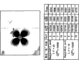
为了试验验证功率传输方案而构建的两个相同螺旋线圈的参数为h=20cm、a=3mm、r=30cm、n=5.25。两个线圈都由铜制成。由于构造的非理想性,螺旋环路之间的间距不均匀,并且我们通过将10%(2cm)的不确定度归因于h而将关于其均匀性的不确定度包括进来。对于给出的这些尺寸,预计谐振频率为f0=10.56±0.3MHz,这与在9.90MHz附近测量到的谐振偏离大约5%。The parameters of two identical helical coils constructed for experimental verification of the power transfer scheme were h = 20 cm, a = 3 mm, r = 30 cm, n = 5.25. Both coils are made of copper. Due to constructional non-idealities, the spacing between the helical loops is not uniform, and we include uncertainty about its uniformity by attributing an uncertainty of 10% (2 cm) to h. Given these dimensions, the predicted resonance frequency is f 0 =10.56 ± 0.3 MHz, which deviates by about 5% from the resonance measured around 9.90 MHz.
环路的理论Q的估计值是~2500(假设电阻率为ρ=1.7×10⁻⁸Ωm的完美的铜),但测量值是950±50。我们认为偏差主要是由铜线表面上导电差的氧化铜层的影响所造成的,在这一频率上电流被短的趋肤深度(~20μm)约束到这一层。因此,在所有后续计算中我们使用试验观察到的Q(以及从其导出的Γ1=Γ2=Γ=ω/(2Q))。The theoretical Q of the loop is estimated to be ~2500 (assuming perfect copper with a resistivity p = 1.7 x 10 -8 Ωm), but the measured value is 950 ± 50. We believe that the deviation is mainly caused by the influence of the poorly conducting copper oxide layer on the surface of the copper wire, to which the current is confined by the short skin depth (~20 μm) at this frequency. We therefore use the experimentally observed Q (and Γ 1 =Γ 2 =Γ = ω/(2Q) derived therefrom) in all subsequent calculations.
通过相隔距离D放置两个自谐振线圈(在隔离开时,通过轻微调节h将其精细调谐到相同谐振频率)并测量两个谐振模式的频率的分隔距离来找到耦合系数κ。根据耦合模理论,该分隔距离应该是
图16示出了作为两个线圈之间的间隔的函数的参数κ/Γ的试验值和理论值的比较。理论值是利用理论上获得的κ和试验测量的Γ获得的。阴影区代表由于Q的5%不确定度导致的理论κ/Γ的扩展。Figure 16 shows a comparison of experimental and theoretical values for the parameter κ/Γ as a function of the spacing between the two coils. Theoretical values are obtained using theoretically obtained κ and experimentally measured Γ. The shaded area represents the expansion of theoretical κ/Γ due to the 5% uncertainty in Q.
如上所述,最大理论效率仅取决于参数
电源电路是借助半径为25cm的单个铜线环路而电感性耦合到源线圈的标准科尔波兹振荡器(参见图14)。负载由先前校准过的灯泡构成,并且该负载附着到其自己的绝缘线环路上,该负载又被放置在装置线圈附近并电感性地耦合到装置线圈上。于是,通过改变灯泡和装置线圈之间的距离,调节参数Γw/Γ,使得它匹配其最佳值,在理论上其最佳值由
为了隔绝特别是在源线圈和负载之间发生的传输效率,利用电流探针(发现其未显著降低线圈的Q)在每个自谐振线圈的中点处测量电流。这给出了以上定义的电流参数I1和I2的测量值。然后利用P1,2=ΓL|I1,2|2计算每个线圈中消耗的功率,并直接从η=Pw/(P1+P2+Pw)获得效率。为了确保用两个物体的耦合模理论模型来很好地描述实验装置,放置该装置线圈,使得其到附着到科尔波兹振荡器的铜环的直接耦合为零。图17中示出了试验结果以及由方程(14)给出的最高效率的理论预计。To isolate the transfer efficiency occurring especially between the source coil and the load, the current was measured at the midpoint of each self-resonant coil using a current probe (which was found to not significantly degrade the Q of the coil). This gives the measured values of the current parameters I1 and I2 defined above. The power consumed in each coil is then calculated using P 1,2 =ΓL|I 1,2 | 2 and the efficiency is obtained directly from η=P w /(P 1 +P 2 +P w ). To ensure that the experimental setup was well described by the coupled mode theoretical model of the two objects, the setup coil was placed such that its direct coupling to the copper ring attached to the Kohlberg oscillator was zero. The experimental results are shown in Figure 17 together with the theoretical prediction of maximum efficiency given by equation (14).
利用本实施例,我们能够利用该装置传输大量功率,从例如2m远的距离完全点亮60W的灯泡。作为额外的测试,我们还测量了进入驱动电路的总功率。然而,通过这种方式难以估计无线传输自身的效率,这是因为未确切知道科尔波兹振荡器自身的效率,尽管预计其远不到100%。尽管如此,这给出了效率的过分保守的下限。例如,在通过2m的距离向负载传输60W时,流入驱动电路的功率为400W。这获得了~15%的总的墙-负载效率,考虑到该距离处无线功率传输的预计~40%的效率和驱动电路的低效率,这是合理的。Using this embodiment, we are able to use the device to deliver large amounts of power to fully light a 60W bulb from a distance of, say, 2m. As an additional test, we also measured the total power going into the drive circuit. However, it is difficult to estimate the efficiency of the wireless transmission itself in this way, since the efficiency of the Cole Potz oscillator itself is not known exactly, although it is expected to be far less than 100%. Nonetheless, this gives an overly conservative lower bound on efficiency. For example, when 60W is transmitted to the load through a distance of 2m, the power flowing into the drive circuit is 400W. This yields an overall wall-load efficiency of ~15%, which is reasonable given the projected ~40% efficiency of wireless power transfer at this distance and the inefficiency of the drive circuitry.
从以上理论处理我们看到,在典型实施例中,为了实用,重要的是用于功率传输的线圈处于谐振。我们通过试验发现,当线圈之一被去调谐而偏离谐振时,传输到负载的功率急剧下降。对于是反向负载Q几倍的极小去调谐Δf/f0,装置线圈中诱发的电流难以与噪声区分开。From the above theoretical treatment we see that, in typical embodiments, for practicality it is important that the coils used for power transfer be at resonance. We have found experimentally that when one of the coils is detuned away from resonance, the power delivered to the load drops dramatically. For an extremely small detuning Δf/f 0 that is several times the reverse load Q, the current induced in the device coil is indistinguishable from noise.
在两个线圈之间放置人和各种日常物品,例如金属和木制家具,以及大的和小的电子装置时,即使它们严重遮挡了源和装置之间的视线,也未发现功率传输受到明显影响。仅在外部物体距任一个线圈的距离小于10cm时,才发现有影响。尽管一些材料(例如铝箔、聚苯乙烯泡沫塑料和人)大多仅仅使谐振频率偏移(原则上可以利用上述类型的反馈电路容易地对其加以校正),但其他物体(纸板、木头和PVC)在放置得距线圈小于几厘米时会降低Q,从而降低传输的效率。When placing people and various everyday objects such as metal and wooden furniture, as well as large and small electronic devices, between the two coils, the power transfer was not found to be affected even though they severely obstructed the line of sight between the source and the device. obvious impact. An effect was only seen when the distance of the external object was less than 10 cm from either coil. While some materials (such as aluminum foil, Styrofoam, and people) mostly only shift the resonant frequency (which can in principle be easily corrected with a feedback circuit of the type described above), others (cardboard, wood, and PVC) Placing it less than a few centimeters from the coil will lower the Q, thereby reducing the efficiency of the transmission.
我们相信这种功率传输方法应当对人是安全的。在跨越2m传输60W(超过足以为膝上型计算机供电的功率)时,我们估计:对于所有距离来说,所产生磁场的幅度比地球磁场微弱得多,但距线圈中导线小于约1cm除外,这表明即使长期使用之后方案仍然是安全的。对于这些参数而言,辐射的功率为5W,大致比手机高一个数量级,但如下所述,可以大大减小。We believe this method of power transfer should be safe for humans. In transmitting 60W (more than enough power to power a laptop) across 2m, we estimate that the magnitude of the resulting magnetic field is much weaker than the Earth's magnetic field for all distances except less than about 1cm from the wire in the coil, This shows that the scheme is safe even after long-term use. For these parameters, the radiated power is 5W, which is roughly an order of magnitude higher than that of a mobile phone, but can be significantly reduced as described below.
尽管当前的两个线圈具有相同的尺寸,但可以将装置线圈做得足够小以装配到便携式装置中而不会降低效率。例如,可以将源线圈和装置线圈的特征尺寸之积维持恒定。Although the current two coils are the same size, the device coil can be made small enough to fit into a portable device without loss of efficiency. For example, the product of the characteristic dimensions of the source coil and the device coil can be held constant.
这些试验以试验方式展示了通过中等距离传输功率的系统,在多次独立且相互协调的测试中发现试验结果与理论吻合得很好。The trials demonstrated experimentally the system for transmitting power over moderate distances, and the experimental results were found to be in good agreement with theory in multiple independent and coordinated tests.
我们认为:通过为线圈镀银或通过用更精细几何性质的谐振物体进行工作能够明显地改善方案的效率和覆盖的距离,镀银将增大它们的Q。尽管如此,这里提供的系统的性能特性已经处于可用于实际应用的水平。We believe that the efficiency of the scheme and the distance covered can be significantly improved by silvering the coils or by working with resonant objects of finer geometry, which will increase their Q. Nevertheless, the performance characteristics of the system presented here are already at a level that can be used for practical applications.
应用application
总之,已经描述了用于无线非辐射能量传输的基于谐振的方案的若干实施例。尽管我们考虑的是静态几何性质(即κ和Γe是与时间无关的),但所有结果可以直接适用于移动物体的动态几何性质,这是因为能量传输时间κ-1(对于微波应用而言,~1μs-1ms)比与宏观物体运动相关的任何时间尺度要短得多。分析非常简单实现方式的几何性质提供了令人鼓舞的性能特性,预计利用认真的设计优化能够做出进一步改善。于是,对于很多现代应用而言,所提出的机制很有前景。In summary, several embodiments of resonance-based schemes for wireless non-radiative energy transfer have been described. Although we consider static geometric properties (i.e., κ and Γ e are time-independent), all results can be directly applied to dynamic geometric properties of moving objects, because the energy transmission time κ -1 (for microwave applications , ~1 μs-1ms) are much shorter than any time scale associated with the motion of macroscopic objects. Analyzing the geometry of a very simple implementation provides encouraging performance characteristics, and further improvements are expected with careful design optimization. Thus, the proposed mechanism is promising for many modern applications.
例如,在宏观世界中,可以将这种方案用于为厂房中的机器人和/或计算机供电,或为高速公路上的电动公共汽车供电。在一些实施例中,源物体可以是运行于高速公路上或沿顶棚运行的细长“管路”。In the macro world, for example, such a scheme could be used to power robots and/or computers in a factory building, or electric buses on a highway. In some embodiments, the source object may be an elongated "pipe" running on a highway or along a ceiling.
无线传输方案的一些实施例能够提供能量,以利用导线或其他技术为难以触及或不可能触及的装置供电或充电。例如,一些实施例可以向植入的医疗器械(例如人工心脏、起搏器、药物输送泵等)或地下埋藏的传感器供电。Some embodiments of wireless transmission schemes can provide energy to power or charge devices that are difficult or impossible to reach using wires or other technologies. For example, some embodiments may power implanted medical devices (eg, artificial hearts, pacemakers, drug delivery pumps, etc.) or sensors buried underground.
在微观世界中,要使用小得多的波长且需要更小的功率,可以使用它来实现CMOS电子线路的光学互连,或向独立纳米物体(例如MEMS或纳米机器人)传输能量,而无需过多担心源与装置之间的相对对准。此外,可以将可用范围扩展到声学系统,其中经由公共凝聚态物质物体连接源与装置。In the microscopic world, much smaller wavelengths are used and less power is required, and it can be used to realize the optical interconnection of CMOS electronic circuits, or to transfer energy to independent nano-objects (such as MEMS or nano-robots) without excessive Concerns about relative alignment between source and device. Furthermore, the usable range can be extended to acoustic systems where the source and device are connected via a common condensed matter object.
在一些实施例中,上述技术能够利用谐振物体的局域化近场提供信息的非辐射无线传输。这样的方案提供了更大的安全性,这是因为没有信息会辐射到远场中,并且这样的方案非常适于高度敏感信息的中距离通信。In some embodiments, the techniques described above can provide non-radiative wireless transfer of information using the localized near-field of a resonant object. Such a scheme provides greater security since no information is radiated into the far field and is well suited for mid-range communication of highly sensitive information.
已经描述了本发明的若干实施例。尽管如此,应当理解的是,可以在不脱离本发明精神和范围的前提下做出各种修改。Several embodiments of the invention have been described. Nevertheless, it should be understood that various modifications may be made without departing from the spirit and scope of the invention.
Claims (18)
Priority Applications (3)
| Application Number | Priority Date | Filing Date | Title |
|---|---|---|---|
| CN201110311000.XA CN102361358B (en) | 2007-03-27 | 2007-06-11 | Wireless energy transfer |
| CN201310280724.1A CN103384095B (en) | 2007-03-27 | 2007-06-11 | For the equipment of wireless energy transfer |
| CN201310098809.8A CN103633745B (en) | 2007-03-27 | 2007-06-11 | Method for wireless energy transfer |
Applications Claiming Priority (5)
| Application Number | Priority Date | Filing Date | Title |
|---|---|---|---|
| US90838307P | 2007-03-27 | 2007-03-27 | |
| US60/908,383 | 2007-03-27 | ||
| US90866607P | 2007-03-28 | 2007-03-28 | |
| US60/908,666 | 2007-03-28 | ||
| PCT/US2007/070892 WO2008118178A1 (en) | 2007-03-27 | 2007-06-11 | Wireless energy transfer |
Related Child Applications (3)
| Application Number | Title | Priority Date | Filing Date |
|---|---|---|---|
| CN201310280724.1A Division CN103384095B (en) | 2007-03-27 | 2007-06-11 | For the equipment of wireless energy transfer |
| CN201310098809.8A Division CN103633745B (en) | 2007-03-27 | 2007-06-11 | Method for wireless energy transfer |
| CN201110311000.XA Division CN102361358B (en) | 2007-03-27 | 2007-06-11 | Wireless energy transfer |
Publications (2)
| Publication Number | Publication Date |
|---|---|
| CN101682216A CN101682216A (en) | 2010-03-24 |
| CN101682216B true CN101682216B (en) | 2013-06-26 |
Family
ID=39060219
Family Applications (4)
| Application Number | Title | Priority Date | Filing Date |
|---|---|---|---|
| CN2007800531263A Active CN101682216B (en) | 2007-03-27 | 2007-06-11 | wireless energy transfer |
| CN201310098809.8A Active CN103633745B (en) | 2007-03-27 | 2007-06-11 | Method for wireless energy transfer |
| CN201110311000.XA Active CN102361358B (en) | 2007-03-27 | 2007-06-11 | Wireless energy transfer |
| CN201310280724.1A Active CN103384095B (en) | 2007-03-27 | 2007-06-11 | For the equipment of wireless energy transfer |
Family Applications After (3)
| Application Number | Title | Priority Date | Filing Date |
|---|---|---|---|
| CN201310098809.8A Active CN103633745B (en) | 2007-03-27 | 2007-06-11 | Method for wireless energy transfer |
| CN201110311000.XA Active CN102361358B (en) | 2007-03-27 | 2007-06-11 | Wireless energy transfer |
| CN201310280724.1A Active CN103384095B (en) | 2007-03-27 | 2007-06-11 | For the equipment of wireless energy transfer |
Country Status (7)
| Country | Link |
|---|---|
| EP (2) | EP2130287A1 (en) |
| JP (5) | JP5190108B2 (en) |
| KR (5) | KR20110117732A (en) |
| CN (4) | CN101682216B (en) |
| AU (1) | AU2007349874B2 (en) |
| CA (1) | CA2682284C (en) |
| WO (1) | WO2008118178A1 (en) |
Families Citing this family (304)
| Publication number | Priority date | Publication date | Assignee | Title |
|---|---|---|---|---|
| US7825543B2 (en) | 2005-07-12 | 2010-11-02 | Massachusetts Institute Of Technology | Wireless energy transfer |
| AU2006269374C1 (en) | 2005-07-12 | 2010-03-25 | Massachusetts Institute Of Technology | Wireless non-radiative energy transfer |
| CN101682216B (en) * | 2007-03-27 | 2013-06-26 | 麻省理工学院 | wireless energy transfer |
| US9421388B2 (en) | 2007-06-01 | 2016-08-23 | Witricity Corporation | Power generation for implantable devices |
| US8805530B2 (en) | 2007-06-01 | 2014-08-12 | Witricity Corporation | Power generation for implantable devices |
| EP2195905A4 (en) * | 2007-09-17 | 2017-03-22 | Qualcomm Incorporated | High efficiency and power transfer in wireless power magnetic resonators |
| JP4453741B2 (en) | 2007-10-25 | 2010-04-21 | トヨタ自動車株式会社 | Electric vehicle and vehicle power supply device |
| US8294300B2 (en) * | 2008-01-14 | 2012-10-23 | Qualcomm Incorporated | Wireless powering and charging station |
| WO2009140506A1 (en) * | 2008-05-14 | 2009-11-19 | Massachusetts Institute Of Technology | Wireless energy transfer, including interference enhancement |
| US8421409B2 (en) | 2008-09-19 | 2013-04-16 | Toyota Jidosha Kabushiki Kaisha | Noncontact power receiving apparatus for electrically-powered vehicle and vehicle including the same |
| JP5390818B2 (en) * | 2008-09-19 | 2014-01-15 | 矢崎総業株式会社 | Communication coil structure of wireless power transmission device |
| US8970060B2 (en) | 2008-09-25 | 2015-03-03 | Toyota Jidosha Kabushiki Kaisha | Power feeding system and electrical powered vehicle |
| US8410636B2 (en) | 2008-09-27 | 2013-04-02 | Witricity Corporation | Low AC resistance conductor designs |
| US8901779B2 (en) | 2008-09-27 | 2014-12-02 | Witricity Corporation | Wireless energy transfer with resonator arrays for medical applications |
| US9544683B2 (en) | 2008-09-27 | 2017-01-10 | Witricity Corporation | Wirelessly powered audio devices |
| US9065423B2 (en) | 2008-09-27 | 2015-06-23 | Witricity Corporation | Wireless energy distribution system |
| US8947186B2 (en) | 2008-09-27 | 2015-02-03 | Witricity Corporation | Wireless energy transfer resonator thermal management |
| US9318922B2 (en) | 2008-09-27 | 2016-04-19 | Witricity Corporation | Mechanically removable wireless power vehicle seat assembly |
| US9106203B2 (en) | 2008-09-27 | 2015-08-11 | Witricity Corporation | Secure wireless energy transfer in medical applications |
| US8471410B2 (en) | 2008-09-27 | 2013-06-25 | Witricity Corporation | Wireless energy transfer over distance using field shaping to improve the coupling factor |
| US8901778B2 (en) | 2008-09-27 | 2014-12-02 | Witricity Corporation | Wireless energy transfer with variable size resonators for implanted medical devices |
| KR101789904B1 (en) | 2008-09-27 | 2017-10-25 | 위트리시티 코포레이션 | Wireless energy transfer systems |
| US8669676B2 (en) | 2008-09-27 | 2014-03-11 | Witricity Corporation | Wireless energy transfer across variable distances using field shaping with magnetic materials to improve the coupling factor |
| US8937408B2 (en) | 2008-09-27 | 2015-01-20 | Witricity Corporation | Wireless energy transfer for medical applications |
| US8963488B2 (en) | 2008-09-27 | 2015-02-24 | Witricity Corporation | Position insensitive wireless charging |
| US8324759B2 (en) | 2008-09-27 | 2012-12-04 | Witricity Corporation | Wireless energy transfer using magnetic materials to shape field and reduce loss |
| US8629578B2 (en) | 2008-09-27 | 2014-01-14 | Witricity Corporation | Wireless energy transfer systems |
| US8686598B2 (en) | 2008-09-27 | 2014-04-01 | Witricity Corporation | Wireless energy transfer for supplying power and heat to a device |
| US8907531B2 (en) | 2008-09-27 | 2014-12-09 | Witricity Corporation | Wireless energy transfer with variable size resonators for medical applications |
| US9601266B2 (en) | 2008-09-27 | 2017-03-21 | Witricity Corporation | Multiple connected resonators with a single electronic circuit |
| US8441154B2 (en) | 2008-09-27 | 2013-05-14 | Witricity Corporation | Multi-resonator wireless energy transfer for exterior lighting |
| US9601261B2 (en) | 2008-09-27 | 2017-03-21 | Witricity Corporation | Wireless energy transfer using repeater resonators |
| US8497601B2 (en) | 2008-09-27 | 2013-07-30 | Witricity Corporation | Wireless energy transfer converters |
| US8461721B2 (en) | 2008-09-27 | 2013-06-11 | Witricity Corporation | Wireless energy transfer using object positioning for low loss |
| US9246336B2 (en) | 2008-09-27 | 2016-01-26 | Witricity Corporation | Resonator optimizations for wireless energy transfer |
| US9035499B2 (en) | 2008-09-27 | 2015-05-19 | Witricity Corporation | Wireless energy transfer for photovoltaic panels |
| US8643326B2 (en) | 2008-09-27 | 2014-02-04 | Witricity Corporation | Tunable wireless energy transfer systems |
| US8912687B2 (en) | 2008-09-27 | 2014-12-16 | Witricity Corporation | Secure wireless energy transfer for vehicle applications |
| US8772973B2 (en) | 2008-09-27 | 2014-07-08 | Witricity Corporation | Integrated resonator-shield structures |
| US8587153B2 (en) | 2008-09-27 | 2013-11-19 | Witricity Corporation | Wireless energy transfer using high Q resonators for lighting applications |
| US8692410B2 (en) | 2008-09-27 | 2014-04-08 | Witricity Corporation | Wireless energy transfer with frequency hopping |
| US9744858B2 (en) | 2008-09-27 | 2017-08-29 | Witricity Corporation | System for wireless energy distribution in a vehicle |
| US8461722B2 (en) | 2008-09-27 | 2013-06-11 | Witricity Corporation | Wireless energy transfer using conducting surfaces to shape field and improve K |
| US9093853B2 (en) | 2008-09-27 | 2015-07-28 | Witricity Corporation | Flexible resonator attachment |
| US9515494B2 (en) | 2008-09-27 | 2016-12-06 | Witricity Corporation | Wireless power system including impedance matching network |
| US8400017B2 (en) | 2008-09-27 | 2013-03-19 | Witricity Corporation | Wireless energy transfer for computer peripheral applications |
| US8482158B2 (en) | 2008-09-27 | 2013-07-09 | Witricity Corporation | Wireless energy transfer using variable size resonators and system monitoring |
| US8487480B1 (en) | 2008-09-27 | 2013-07-16 | Witricity Corporation | Wireless energy transfer resonator kit |
| US9577436B2 (en) | 2008-09-27 | 2017-02-21 | Witricity Corporation | Wireless energy transfer for implantable devices |
| US8946938B2 (en) | 2008-09-27 | 2015-02-03 | Witricity Corporation | Safety systems for wireless energy transfer in vehicle applications |
| US8304935B2 (en) | 2008-09-27 | 2012-11-06 | Witricity Corporation | Wireless energy transfer using field shaping to reduce loss |
| US9184595B2 (en) | 2008-09-27 | 2015-11-10 | Witricity Corporation | Wireless energy transfer in lossy environments |
| US8587155B2 (en) | 2008-09-27 | 2013-11-19 | Witricity Corporation | Wireless energy transfer using repeater resonators |
| US8552592B2 (en) | 2008-09-27 | 2013-10-08 | Witricity Corporation | Wireless energy transfer with feedback control for lighting applications |
| US8476788B2 (en) | 2008-09-27 | 2013-07-02 | Witricity Corporation | Wireless energy transfer with high-Q resonators using field shaping to improve K |
| US8598743B2 (en) | 2008-09-27 | 2013-12-03 | Witricity Corporation | Resonator arrays for wireless energy transfer |
| US8922066B2 (en) | 2008-09-27 | 2014-12-30 | Witricity Corporation | Wireless energy transfer with multi resonator arrays for vehicle applications |
| US9105959B2 (en) | 2008-09-27 | 2015-08-11 | Witricity Corporation | Resonator enclosure |
| US8957549B2 (en) | 2008-09-27 | 2015-02-17 | Witricity Corporation | Tunable wireless energy transfer for in-vehicle applications |
| US9601270B2 (en) | 2008-09-27 | 2017-03-21 | Witricity Corporation | Low AC resistance conductor designs |
| US8723366B2 (en) | 2008-09-27 | 2014-05-13 | Witricity Corporation | Wireless energy transfer resonator enclosures |
| US8933594B2 (en) | 2008-09-27 | 2015-01-13 | Witricity Corporation | Wireless energy transfer for vehicles |
| US8692412B2 (en) | 2008-09-27 | 2014-04-08 | Witricity Corporation | Temperature compensation in a wireless transfer system |
| US8928276B2 (en) | 2008-09-27 | 2015-01-06 | Witricity Corporation | Integrated repeaters for cell phone applications |
| US8466583B2 (en) | 2008-09-27 | 2013-06-18 | Witricity Corporation | Tunable wireless energy transfer for outdoor lighting applications |
| US8461720B2 (en) | 2008-09-27 | 2013-06-11 | Witricity Corporation | Wireless energy transfer using conducting surfaces to shape fields and reduce loss |
| US9396867B2 (en) | 2008-09-27 | 2016-07-19 | Witricity Corporation | Integrated resonator-shield structures |
| US9160203B2 (en) | 2008-09-27 | 2015-10-13 | Witricity Corporation | Wireless powered television |
| EP2345100B1 (en) | 2008-10-01 | 2018-12-05 | Massachusetts Institute of Technology | Efficient near-field wireless energy transfer using adiabatic system variations |
| WO2010041320A1 (en) | 2008-10-09 | 2010-04-15 | トヨタ自動車株式会社 | Electric vehicle |
| EP2346142B1 (en) | 2008-10-09 | 2017-01-11 | Toyota Jidosha Kabushiki Kaisha | Non-contact power reception device and vehicle including the same |
| CN102177042B (en) | 2008-10-09 | 2013-10-23 | 丰田自动车株式会社 | Non-contact power transmission device and vehicle with non-contact power transmission device |
| JP5114364B2 (en) * | 2008-11-04 | 2013-01-09 | 株式会社豊田自動織機 | Non-contact power transmission device and design method thereof |
| JP5375032B2 (en) | 2008-11-04 | 2013-12-25 | 株式会社豊田自動織機 | Non-contact power transmission device and design method of non-contact power transmission device |
| JP4849190B2 (en) | 2008-11-07 | 2012-01-11 | トヨタ自動車株式会社 | Vehicle power supply system and electric vehicle |
| JP5441392B2 (en) * | 2008-11-12 | 2014-03-12 | キヤノン株式会社 | Electronic apparatus and method |
| JP5308127B2 (en) * | 2008-11-17 | 2013-10-09 | 株式会社豊田中央研究所 | Power supply system |
| US8294419B2 (en) | 2008-11-21 | 2012-10-23 | Toyota Jidosha Kabushiki Kaisha | Electrical powered vehicle |
| JP5515659B2 (en) * | 2008-12-01 | 2014-06-11 | 株式会社豊田自動織機 | Non-contact power transmission device |
| JP5114372B2 (en) * | 2008-12-09 | 2013-01-09 | 株式会社豊田自動織機 | Power transmission method and non-contact power transmission apparatus in non-contact power transmission apparatus |
| JP5114371B2 (en) * | 2008-12-09 | 2013-01-09 | 株式会社豊田自動織機 | Non-contact power transmission device |
| JP5324901B2 (en) * | 2008-12-09 | 2013-10-23 | 日立コンシューマエレクトロニクス株式会社 | Non-contact power transmission system |
| JP5238472B2 (en) * | 2008-12-16 | 2013-07-17 | 株式会社日立製作所 | Power transmission device and power reception device |
| JP4478729B1 (en) | 2008-12-24 | 2010-06-09 | 株式会社豊田自動織機 | Resonant non-contact charging device |
| JP5285418B2 (en) | 2008-12-24 | 2013-09-11 | 株式会社豊田自動織機 | Resonant non-contact power supply device |
| JP5262785B2 (en) * | 2009-02-09 | 2013-08-14 | 株式会社豊田自動織機 | Non-contact power transmission device |
| JP2010183814A (en) | 2009-02-09 | 2010-08-19 | Toyota Industries Corp | Non-contact power transmitter |
| US8963486B2 (en) * | 2009-02-13 | 2015-02-24 | Qualcomm Incorporated | Wireless power from renewable energy |
| JP2010193598A (en) * | 2009-02-17 | 2010-09-02 | Nippon Soken Inc | Contactless power supply equipment and contactless power supply system |
| JP4911262B2 (en) | 2009-03-12 | 2012-04-04 | トヨタ自動車株式会社 | Electric vehicle |
| DE102009013034B4 (en) | 2009-03-16 | 2015-11-19 | Olympus Winter & Ibe Gmbh | Autoclavable charging device for an energy store of a surgical instrument and method for charging a rechargeable energy store in an autoclaved surgical instrument or for an autoclaved surgical instrument |
| KR101278399B1 (en) * | 2009-03-17 | 2013-06-24 | 후지쯔 가부시끼가이샤 | Wireless power supply system |
| US8692413B2 (en) | 2009-03-18 | 2014-04-08 | Toyota Jidosha Kabushiki Kaisha | Noncontact electric power receiving device, noncontact electric power transmitting device, noncontact electric power feeding system, and vehicle |
| KR101251436B1 (en) | 2009-03-30 | 2013-04-05 | 후지쯔 가부시끼가이샤 | Wireless power supply system, wireless power transmission device, and wireless power receiving device |
| JP5417941B2 (en) | 2009-03-31 | 2014-02-19 | 富士通株式会社 | Power transmission equipment |
| JP5689587B2 (en) * | 2009-03-31 | 2015-03-25 | 富士通株式会社 | Power transmission equipment |
| JP5515368B2 (en) | 2009-03-31 | 2014-06-11 | 富士通株式会社 | Wireless power supply method and wireless power supply system |
| JP4865001B2 (en) | 2009-04-13 | 2012-02-01 | 株式会社日本自動車部品総合研究所 | Non-contact power supply equipment, non-contact power receiving device and non-contact power supply system |
| JP2010252468A (en) * | 2009-04-14 | 2010-11-04 | Sony Corp | Power transmission device and method, power reception device and method, and power transmission system |
| JP5355783B2 (en) * | 2009-05-07 | 2013-11-27 | テレコム・イタリア・エッセ・ピー・アー | A system to transmit energy wirelessly |
| EP2431213B1 (en) | 2009-05-14 | 2018-03-14 | Toyota Jidosha Kabushiki Kaisha | Vehicle charging unit |
| BRPI0924914A2 (en) | 2009-05-14 | 2016-08-30 | Toyota Motor Co Ltd | contactless energy capture equipment and vehicle incorporating the same |
| WO2010131349A1 (en) | 2009-05-14 | 2010-11-18 | トヨタ自動車株式会社 | Vehicle charging unit |
| JP5625263B2 (en) * | 2009-05-18 | 2014-11-19 | トヨタ自動車株式会社 | Coil unit, non-contact power transmission device, non-contact power supply system, and electric vehicle |
| EP2515414A4 (en) | 2009-11-18 | 2016-04-06 | Toshiba Kk | WIRELESS POWER TRANSMISSION DEVICE |
| US9461505B2 (en) | 2009-12-03 | 2016-10-04 | Mitsubishi Electric Research Laboratories, Inc. | Wireless energy transfer with negative index material |
| CN102656648A (en) | 2009-12-17 | 2012-09-05 | 丰田自动车株式会社 | Shield and vehicle whereupon same is mounted |
| WO2011077493A1 (en) * | 2009-12-25 | 2011-06-30 | 株式会社 東芝 | Wireless power transmission device and power receiving device |
| JP5638382B2 (en) * | 2009-12-29 | 2014-12-10 | ミツビシ・エレクトリック・リサーチ・ラボラトリーズ・インコーポレイテッド | Wireless energy transfer method and system using energy repeater |
| US8384247B2 (en) * | 2010-01-13 | 2013-02-26 | Mitsubishi Electric Research Laboratories, Inc. | Wireless energy transfer to moving devices |
| JP5392358B2 (en) | 2010-01-18 | 2014-01-22 | トヨタ自動車株式会社 | Contactless power receiving device, contactless power transmitting device |
| CN102754305B (en) * | 2010-02-10 | 2016-09-07 | 富士通株式会社 | Resonant frequency control method, power transmitting device, and power receiving device |
| JP5051257B2 (en) | 2010-03-16 | 2012-10-17 | トヨタ自動車株式会社 | vehicle |
| US8674550B2 (en) * | 2010-03-25 | 2014-03-18 | General Electric Company | Contactless power transfer system and method |
| JP5408343B2 (en) | 2010-04-21 | 2014-02-05 | トヨタ自動車株式会社 | Vehicle parking assist device and electric vehicle including the same |
| WO2011132272A1 (en) | 2010-04-21 | 2011-10-27 | トヨタ自動車株式会社 | Vehicle parking assistance device and electric vehicle equipped with same |
| KR101718715B1 (en) | 2010-04-28 | 2017-03-22 | 삼성전자주식회사 | Method and Apparatus of Controlling of Resonance Bandwidth in Wireless Power Transform System |
| KR101394963B1 (en) * | 2010-07-29 | 2014-05-16 | 한국전자통신연구원 | Wireless power transmitter, wireless power receiver, and method for wireless power transfer using them |
| KR101441453B1 (en) | 2010-08-25 | 2014-09-18 | 한국전자통신연구원 | Apparatus and method for reducing electric field and radiation field in magnetic resonant coupling coils or magnetic induction device for wireless energy transfer |
| US9602168B2 (en) | 2010-08-31 | 2017-03-21 | Witricity Corporation | Communication in wireless energy transfer systems |
| JP5718619B2 (en) | 2010-11-18 | 2015-05-13 | トヨタ自動車株式会社 | Coil unit, contactless power transmission device, vehicle, and contactless power supply system |
| CN103250325B (en) | 2010-12-01 | 2015-04-08 | 丰田自动车株式会社 | Non-contact power supply equipment |
| EP2651008B1 (en) | 2010-12-01 | 2016-11-23 | Toyota Jidosha Kabushiki Kaisha | Wireless power feeding apparatus, vehicle, and method of controlling wireless power feeding system |
| WO2012086051A1 (en) | 2010-12-24 | 2012-06-28 | トヨタ自動車株式会社 | Contactless power supply system, vehicle, power supply facility, and contactless power supply system control method |
| US9197093B2 (en) | 2010-12-24 | 2015-11-24 | Toyota Jidosha Kabushiki Kaisha | Non-contact charging system, non-contact charging method, non-contact charging type vehicle, and non-contact charging management apparatus |
| JP5776703B2 (en) | 2011-02-04 | 2015-09-09 | トヨタ自動車株式会社 | Vehicle and external power supply device |
| US9440543B2 (en) | 2011-02-15 | 2016-09-13 | Toyota Jidosha Kabushiki Kaisha | Vehicle and external power feeding apparatus |
| EP2677627B1 (en) | 2011-02-15 | 2018-04-25 | Toyota Jidosha Kabushiki Kaisha | Non-contact power receiving apparatus, vehicle having the non-contact power receiving apparatus mounted therein and non-contact power supply equipment |
| WO2012124029A1 (en) | 2011-03-11 | 2012-09-20 | トヨタ自動車株式会社 | Coil unit, power transmission device, external power supply device, and vehicle charging system |
| US8849402B2 (en) * | 2011-03-21 | 2014-09-30 | General Electric Company | System and method for contactless power transfer in implantable devices |
| JP5796987B2 (en) | 2011-04-07 | 2015-10-21 | キヤノン株式会社 | Power supply apparatus, power supply method, and program |
| JP5740200B2 (en) | 2011-04-22 | 2015-06-24 | 矢崎総業株式会社 | Resonant non-contact power feeding system, power receiving side device, and power transmitting side device |
| JP2012244732A (en) | 2011-05-18 | 2012-12-10 | Sony Corp | Electromagnetic coupling state detection circuit, transmission equipment, non-contact power transmission system, and method for detecting electromagnetic coupling state |
| BR112013031037B1 (en) | 2011-06-03 | 2024-03-12 | Toyota Jidosha Kabushiki Kaisha | VEHICLE AND POWER TRANSMISSION/RECEPTION SYSTEM |
| WO2012176265A1 (en) | 2011-06-20 | 2012-12-27 | トヨタ自動車株式会社 | Non-contact receiving device, non-contact transmitting device, and non-contact transmitting/receiving system |
| WO2012176264A1 (en) | 2011-06-20 | 2012-12-27 | トヨタ自動車株式会社 | Non-contact power reception device, non-contact power transmission device, and non-contact power reception and transmission system |
| EP2725592B1 (en) | 2011-06-27 | 2016-07-20 | Toyota Jidosha Kabushiki Kaisha | Power receiving device, power transmitting device, and power transmission system |
| US9948145B2 (en) | 2011-07-08 | 2018-04-17 | Witricity Corporation | Wireless power transfer for a seat-vest-helmet system |
| US9379571B2 (en) | 2011-07-11 | 2016-06-28 | Delphi Technologies, Inc. | Electrical charging system having energy coupling arrangement for wireless energy transmission therebetween |
| WO2013009881A2 (en) | 2011-07-11 | 2013-01-17 | Vascor, Inc. | Transcutaneous power transmission and communication for implanted heart assist and other devices |
| AU2012289855A1 (en) | 2011-08-04 | 2014-03-13 | Witricity Corporation | Tunable wireless power architectures |
| WO2013036947A2 (en) | 2011-09-09 | 2013-03-14 | Witricity Corporation | Foreign object detection in wireless energy transfer systems |
| US20130062966A1 (en) | 2011-09-12 | 2013-03-14 | Witricity Corporation | Reconfigurable control architectures and algorithms for electric vehicle wireless energy transfer systems |
| CN103827996B (en) | 2011-09-28 | 2016-12-28 | 丰田自动车株式会社 | Power receiving device, power transmitting device and power transmission system |
| EP2763149B1 (en) | 2011-09-28 | 2018-03-21 | Toyota Jidosha Kabushiki Kaisha | Power receiving device, power transmitting device, and power transmission system |
| EP2765681B1 (en) | 2011-10-07 | 2019-03-13 | Toyota Jidosha Kabushiki Kaisha | Power reception device, vehicle provided with same, and power transmission system |
| KR101262556B1 (en) * | 2011-10-14 | 2013-05-08 | 엘지이노텍 주식회사 | Wireless power transmission apparatus |
| US9318257B2 (en) | 2011-10-18 | 2016-04-19 | Witricity Corporation | Wireless energy transfer for packaging |
| CN104025422B (en) | 2011-10-27 | 2018-10-30 | 丰田自动车株式会社 | Non-contact power receiving device, non-contact power transmission device and non-contact power transmission are by electric system |
| WO2013061440A1 (en) | 2011-10-27 | 2013-05-02 | トヨタ自動車株式会社 | Non-contact power receiving apparatus, non-contact power transmitting apparatus, and non-contact power transmitting/receiving system |
| HK1200602A1 (en) | 2011-11-04 | 2015-08-07 | WiTricity公司 | Wireless energy transfer modeling tool |
| EP2782108B1 (en) | 2011-11-18 | 2017-02-01 | Toyota Jidosha Kabushiki Kaisha | Power transmitting apparatus, power receiving apparatus, and power transmitting system |
| KR101634889B1 (en) | 2011-11-22 | 2016-06-29 | 도요타지도샤가부시키가이샤 | Power receiving device for vehicle, vehicle provided with same, power supply apparatus, and electric-power transmission system |
| WO2013076804A1 (en) | 2011-11-22 | 2013-05-30 | トヨタ自動車株式会社 | Vehicle and power transmission system |
| WO2013076834A1 (en) | 2011-11-24 | 2013-05-30 | トヨタ自動車株式会社 | Power transmitting device, vehicle, and non-contact power transmitting/receiving system |
| CN103946046A (en) | 2011-11-25 | 2014-07-23 | 丰田自动车株式会社 | vehicle |
| DE102012000409A1 (en) | 2012-01-12 | 2013-07-18 | Phoenix Contact Gmbh & Co. Kg | Modular data system with inductive energy transfer |
| DE102012000408A1 (en) | 2012-01-12 | 2013-07-18 | Phoenix Contact Gmbh & Co. Kg | Resonant inductive power supply device |
| JP5696058B2 (en) | 2012-01-13 | 2015-04-08 | 株式会社東芝 | Power receiving device, power transmitting device and control device |
| US9496731B2 (en) | 2012-01-20 | 2016-11-15 | Samsung Electronics Co., Ltd | Apparatus and method for transmitting wireless power by using resonant coupling and system for the same |
| WO2013113017A1 (en) | 2012-01-26 | 2013-08-01 | Witricity Corporation | Wireless energy transfer with reduced fields |
| EP2810814B1 (en) | 2012-01-30 | 2021-01-13 | Toyota Jidosha Kabushiki Kaisha | Vehicle power receiving device, power supply equipment and electrical power transmission system |
| KR101789836B1 (en) | 2012-02-27 | 2017-10-25 | 한국전자통신연구원 | Apparatus for harvesting the leakage energy |
| KR101844422B1 (en) | 2012-04-19 | 2018-04-03 | 삼성전자주식회사 | Apparatus and method for wireless energy transmission and apparatus wireless energy reception |
| CN104884295B (en) | 2012-05-09 | 2018-01-12 | 丰田自动车株式会社 | Vehicle |
| CN104271384B (en) | 2012-05-09 | 2017-10-10 | 丰田自动车株式会社 | vehicle |
| JP5991372B2 (en) | 2012-05-11 | 2016-09-21 | トヨタ自動車株式会社 | Power transmission device, power reception device, vehicle, and non-contact power supply system |
| US8827889B2 (en) | 2012-05-21 | 2014-09-09 | University Of Washington Through Its Center For Commercialization | Method and system for powering implantable devices |
| US11621583B2 (en) | 2012-05-21 | 2023-04-04 | University Of Washington | Distributed control adaptive wireless power transfer system |
| WO2013183105A1 (en) | 2012-06-04 | 2013-12-12 | トヨタ自動車株式会社 | Power reception device and power transmission device |
| US9343922B2 (en) | 2012-06-27 | 2016-05-17 | Witricity Corporation | Wireless energy transfer for rechargeable batteries |
| US9287607B2 (en) | 2012-07-31 | 2016-03-15 | Witricity Corporation | Resonator fine tuning |
| US10658869B2 (en) | 2012-08-03 | 2020-05-19 | Mediatek Inc. | Multi-mode, multi-standard wireless power transmitter coil assembly |
| US9912197B2 (en) | 2012-08-03 | 2018-03-06 | Mediatek Singapore Pte. Ltd. | Dual-mode wireless power receiver |
| US9859744B2 (en) | 2012-08-03 | 2018-01-02 | Mediatek Singapore Pte. Ltd. | Dual-mode wireless power receiver |
| JP5643270B2 (en) | 2012-09-13 | 2014-12-17 | トヨタ自動車株式会社 | Vehicle and contactless power supply system |
| JP6119756B2 (en) | 2012-09-13 | 2017-04-26 | トヨタ自動車株式会社 | Non-contact power supply system and power transmission device |
| US9595378B2 (en) | 2012-09-19 | 2017-03-14 | Witricity Corporation | Resonator enclosure |
| US9404954B2 (en) | 2012-10-19 | 2016-08-02 | Witricity Corporation | Foreign object detection in wireless energy transfer systems |
| US9449757B2 (en) | 2012-11-16 | 2016-09-20 | Witricity Corporation | Systems and methods for wireless power system with improved performance and/or ease of use |
| JP6222107B2 (en) | 2012-12-11 | 2017-11-01 | トヨタ自動車株式会社 | vehicle |
| CN103105526B (en) * | 2013-01-31 | 2015-09-02 | 广西电网公司电力科学研究院 | The verification method that signal waveform affects resonant inducing wireless energy transmission efficiency |
| JP5967374B2 (en) * | 2013-01-31 | 2016-08-10 | 株式会社エクォス・リサーチ | Noise canceling resonator |
| JP6098708B2 (en) | 2013-02-14 | 2017-03-22 | トヨタ自動車株式会社 | Power receiving device and power transmitting device |
| CN105051842B (en) * | 2013-03-14 | 2017-06-23 | 联发科技(新加坡)私人有限公司 | Electromagnetic resonator and the method for forming electromagnetic resonator |
| DE112013006982B4 (en) | 2013-04-26 | 2023-10-19 | Toyota Jidosha Kabushiki Kaisha | Power receiving device and parking assistance device |
| US9601267B2 (en) * | 2013-07-03 | 2017-03-21 | Qualcomm Incorporated | Wireless power transmitter with a plurality of magnetic oscillators |
| US9857821B2 (en) | 2013-08-14 | 2018-01-02 | Witricity Corporation | Wireless power transfer frequency adjustment |
| JP6110758B2 (en) * | 2013-08-26 | 2017-04-05 | 本田技研工業株式会社 | Vehicle guidance device |
| US9260289B2 (en) * | 2013-09-03 | 2016-02-16 | Northrop Grumman Systems Corporation | Optical-microwave-quantum transducer |
| JP5858018B2 (en) | 2013-09-11 | 2016-02-10 | トヨタ自動車株式会社 | Power receiving device, power transmitting device, and vehicle |
| JP6003853B2 (en) | 2013-09-11 | 2016-10-05 | トヨタ自動車株式会社 | vehicle |
| US9687664B2 (en) * | 2013-09-16 | 2017-06-27 | The Board Of Trustees Of The Leland Stanford Junior University | Multi-element coupler for generation of electromagnetic energy |
| JP6423142B2 (en) | 2013-10-01 | 2018-11-14 | トヨタ自動車株式会社 | Power receiving device, power transmitting device and vehicle |
| ES2535562B2 (en) * | 2013-10-11 | 2016-05-25 | Univ Politècnica De València | WIRELESS POWER TRANSFER DEVICE |
| JP5817813B2 (en) | 2013-11-18 | 2015-11-18 | トヨタ自動車株式会社 | Power receiving device |
| JP6262500B2 (en) | 2013-11-18 | 2018-01-17 | トヨタ自動車株式会社 | Power receiving device |
| JP6060878B2 (en) | 2013-11-20 | 2017-01-18 | トヨタ自動車株式会社 | Vehicle with power transmission / reception unit |
| JP6146272B2 (en) | 2013-11-22 | 2017-06-14 | トヨタ自動車株式会社 | Power receiving device and power transmitting device |
| JP5842901B2 (en) | 2013-12-05 | 2016-01-13 | トヨタ自動車株式会社 | Non-contact power transmission system |
| JP5979125B2 (en) | 2013-12-11 | 2016-08-24 | トヨタ自動車株式会社 | Contactless power transmission equipment |
| JP6361132B2 (en) | 2013-12-24 | 2018-07-25 | トヨタ自動車株式会社 | Contactless power transfer system, charging station, and vehicle |
| JP6260262B2 (en) | 2013-12-25 | 2018-01-17 | トヨタ自動車株式会社 | Non-contact power transmission system and control method thereof |
| US9577449B2 (en) | 2014-01-17 | 2017-02-21 | Honda Motor Co., Ltd. | Method and apparatus to align wireless charging coils |
| JP5910642B2 (en) | 2014-01-22 | 2016-04-27 | トヨタ自動車株式会社 | Contactless charging system |
| JP5937631B2 (en) | 2014-01-31 | 2016-06-22 | トヨタ自動車株式会社 | Contactless power transmission system and charging station |
| JP2015144529A (en) | 2014-01-31 | 2015-08-06 | トヨタ自動車株式会社 | Non-contact power transmission system and charge station |
| JP5920371B2 (en) | 2014-01-31 | 2016-05-18 | トヨタ自動車株式会社 | Non-contact power transmission system |
| JP5962687B2 (en) | 2014-01-31 | 2016-08-03 | トヨタ自動車株式会社 | Contactless power transmission system and charging station |
| US9780573B2 (en) | 2014-02-03 | 2017-10-03 | Witricity Corporation | Wirelessly charged battery system |
| WO2015123614A2 (en) | 2014-02-14 | 2015-08-20 | Witricity Corporation | Object detection for wireless energy transfer systems |
| US9716861B1 (en) | 2014-03-07 | 2017-07-25 | Steelcase Inc. | Method and system for facilitating collaboration sessions |
| US10664772B1 (en) | 2014-03-07 | 2020-05-26 | Steelcase Inc. | Method and system for facilitating collaboration sessions |
| JP6060330B2 (en) | 2014-03-24 | 2017-01-18 | トヨタ自動車株式会社 | Power receiving device, vehicle, and power transmitting device |
| JP6213353B2 (en) | 2014-04-04 | 2017-10-18 | トヨタ自動車株式会社 | Power receiving device and vehicle including the same |
| JP6299362B2 (en) | 2014-04-16 | 2018-03-28 | トヨタ自動車株式会社 | Vehicle and contactless power transmission system |
| US9842687B2 (en) | 2014-04-17 | 2017-12-12 | Witricity Corporation | Wireless power transfer systems with shaped magnetic components |
| US9892849B2 (en) | 2014-04-17 | 2018-02-13 | Witricity Corporation | Wireless power transfer systems with shield openings |
| JP5941094B2 (en) | 2014-04-22 | 2016-06-29 | 株式会社日本自動車部品総合研究所 | Non-contact power transmission / reception system |
| JP6248785B2 (en) | 2014-04-25 | 2017-12-20 | トヨタ自動車株式会社 | Power transmission device and power reception device |
| US9837860B2 (en) | 2014-05-05 | 2017-12-05 | Witricity Corporation | Wireless power transmission systems for elevators |
| EP3140680B1 (en) | 2014-05-07 | 2021-04-21 | WiTricity Corporation | Foreign object detection in wireless energy transfer systems |
| WO2015173847A1 (en) | 2014-05-14 | 2015-11-19 | ネオテス株式会社 | Contactless power transfer device |
| EP3753517B1 (en) | 2014-05-18 | 2022-05-11 | Neuspera Medical Inc. | Midfield coupler |
| US20160336813A1 (en) | 2015-05-15 | 2016-11-17 | NeuSpera Medical Inc. | Midfield coupler |
| US9766079B1 (en) | 2014-10-03 | 2017-09-19 | Steelcase Inc. | Method and system for locating resources and communicating within an enterprise |
| US9955318B1 (en) | 2014-06-05 | 2018-04-24 | Steelcase Inc. | Space guidance and management system and method |
| US9380682B2 (en) | 2014-06-05 | 2016-06-28 | Steelcase Inc. | Environment optimization for space based on presence and activities |
| US11744376B2 (en) | 2014-06-06 | 2023-09-05 | Steelcase Inc. | Microclimate control systems and methods |
| US10433646B1 (en) | 2014-06-06 | 2019-10-08 | Steelcaase Inc. | Microclimate control systems and methods |
| US10614694B1 (en) | 2014-06-06 | 2020-04-07 | Steelcase Inc. | Powered furniture assembly |
| US10135305B2 (en) | 2014-06-10 | 2018-11-20 | Mediatek Singapore Pte. Ltd. | Multi-mode wireless power transmitter |
| JP6131915B2 (en) | 2014-06-11 | 2017-05-24 | トヨタ自動車株式会社 | Power transmission device and power reception device |
| WO2015196123A2 (en) | 2014-06-20 | 2015-12-23 | Witricity Corporation | Wireless power transfer systems for surfaces |
| JP6166227B2 (en) | 2014-07-04 | 2017-07-19 | トヨタ自動車株式会社 | Power transmission device and power reception device |
| US10574091B2 (en) | 2014-07-08 | 2020-02-25 | Witricity Corporation | Enclosures for high power wireless power transfer systems |
| WO2016007674A1 (en) | 2014-07-08 | 2016-01-14 | Witricity Corporation | Resonator balancing in wireless power transfer systems |
| JP6070650B2 (en) | 2014-07-22 | 2017-02-01 | トヨタ自動車株式会社 | Power transmission device, power reception device, and vehicle equipped with the same |
| JP6181614B2 (en) | 2014-08-04 | 2017-08-16 | 株式会社Soken | Non-contact power transmission system |
| JP6260493B2 (en) | 2014-08-20 | 2018-01-17 | トヨタ自動車株式会社 | Power transmission device and manufacturing method thereof, power receiving device and manufacturing method thereof |
| KR102236047B1 (en) | 2014-09-02 | 2021-04-02 | 미쓰비시 덴끼 엔지니어링 가부시키가이샤 | Resonance coupling power transmission system, resonance coupling power transmission device, and resonance coupling power reception device |
| US9852388B1 (en) | 2014-10-03 | 2017-12-26 | Steelcase, Inc. | Method and system for locating resources and communicating within an enterprise |
| JP6550718B2 (en) | 2014-10-28 | 2019-07-31 | トヨタ自動車株式会社 | Power transmission system |
| CN112467886A (en) * | 2014-12-26 | 2021-03-09 | 重庆倍精科技研发有限公司 | High-voltage electric conveying device |
| US9843217B2 (en) | 2015-01-05 | 2017-12-12 | Witricity Corporation | Wireless energy transfer for wearables |
| JP6176272B2 (en) | 2015-02-27 | 2017-08-09 | トヨタ自動車株式会社 | Power transmission system |
| JP6172185B2 (en) | 2015-03-11 | 2017-08-02 | トヨタ自動車株式会社 | Power receiving device and power transmitting device |
| JP6260578B2 (en) | 2015-04-17 | 2018-01-17 | トヨタ自動車株式会社 | Power transmission device and power reception device |
| US10733371B1 (en) | 2015-06-02 | 2020-08-04 | Steelcase Inc. | Template based content preparation system for use with a plurality of space types |
| CN105305644A (en) * | 2015-07-06 | 2016-02-03 | 上海交通大学 | Long-distance wireless transmission device with controllable transmission range |
| JP6304152B2 (en) | 2015-07-10 | 2018-04-04 | トヨタ自動車株式会社 | Non-contact power transmission device and power transmission system |
| JP6142901B2 (en) | 2015-07-17 | 2017-06-07 | トヨタ自動車株式会社 | Non-contact power transmission device and power transmission system |
| JP6176291B2 (en) | 2015-07-21 | 2017-08-09 | トヨタ自動車株式会社 | Non-contact power transmission device and power transmission system |
| JP6304158B2 (en) | 2015-07-21 | 2018-04-04 | トヨタ自動車株式会社 | Non-contact power transmission device and power transmission system |
| JP6287993B2 (en) | 2015-08-04 | 2018-03-07 | トヨタ自動車株式会社 | vehicle |
| JP6458678B2 (en) | 2015-08-05 | 2019-01-30 | トヨタ自動車株式会社 | Coil unit |
| JP6314934B2 (en) | 2015-08-07 | 2018-04-25 | トヨタ自動車株式会社 | vehicle |
| JP6394534B2 (en) | 2015-08-07 | 2018-09-26 | トヨタ自動車株式会社 | Power receiving device and power transmitting device |
| JP6327216B2 (en) | 2015-08-07 | 2018-05-23 | トヨタ自動車株式会社 | Coil unit |
| JP6278012B2 (en) | 2015-08-28 | 2018-02-14 | トヨタ自動車株式会社 | Non-contact power transmission system and power transmission device |
| US10248899B2 (en) | 2015-10-06 | 2019-04-02 | Witricity Corporation | RFID tag and transponder detection in wireless energy transfer systems |
| JP2018538517A (en) | 2015-10-14 | 2018-12-27 | ワイトリシティ コーポレーションWitricity Corporation | Phase and amplitude detection in wireless energy transfer systems |
| WO2017070227A1 (en) | 2015-10-19 | 2017-04-27 | Witricity Corporation | Foreign object detection in wireless energy transfer systems |
| EP3365958B1 (en) | 2015-10-22 | 2020-05-27 | WiTricity Corporation | Dynamic tuning in wireless energy transfer systems |
| US10075019B2 (en) | 2015-11-20 | 2018-09-11 | Witricity Corporation | Voltage source isolation in wireless power transfer systems |
| JP6654031B2 (en) | 2015-12-14 | 2020-02-26 | セイコーインスツル株式会社 | Small electronic equipment |
| CA3012325A1 (en) | 2016-02-02 | 2017-08-10 | Witricity Corporation | Controlling wireless power transfer systems |
| JP6888017B2 (en) | 2016-02-08 | 2021-06-16 | ワイトリシティ コーポレーションWitricity Corporation | PWM capacitor control |
| US9921726B1 (en) | 2016-06-03 | 2018-03-20 | Steelcase Inc. | Smart workstation method and system |
| JP6460068B2 (en) | 2016-09-05 | 2019-01-30 | トヨタ自動車株式会社 | vehicle |
| JP6421807B2 (en) | 2016-10-03 | 2018-11-14 | トヨタ自動車株式会社 | vehicle |
| US10250078B2 (en) * | 2016-10-18 | 2019-04-02 | Robert A Moffatt | Wireless power transfer to multiple receiver devices across a variable-sized area |
| US10264213B1 (en) | 2016-12-15 | 2019-04-16 | Steelcase Inc. | Content amplification system and method |
| EP3339872B1 (en) * | 2016-12-21 | 2019-02-13 | Bruker BioSpin GmbH | Epr resonator with extended transparency and homogeneity in rf range |
| CN106772162B (en) * | 2016-12-26 | 2020-01-14 | 中国科学院长春光学精密机械与物理研究所 | Non-winding form gradient coil for magnetic resonance imaging system and design method thereof |
| CN110999029A (en) | 2017-05-30 | 2020-04-10 | 无线先进车辆电气化有限公司 | Single-point feed multi-pad wireless charging |
| JP6798428B2 (en) | 2017-06-08 | 2020-12-09 | トヨタ自動車株式会社 | Power transmission device and power receiving device |
| JP2019009161A (en) | 2017-06-21 | 2019-01-17 | トヨタ自動車株式会社 | Coil unit |
| EP3646434B1 (en) | 2017-06-29 | 2025-01-22 | Witricity Corporation | Protection and control of wireless power systems |
| JP6825501B2 (en) | 2017-07-03 | 2021-02-03 | トヨタ自動車株式会社 | Power transmission device and power receiving device |
| JP6897371B2 (en) | 2017-07-03 | 2021-06-30 | トヨタ自動車株式会社 | Vehicle and power transmission system |
| JP6772978B2 (en) | 2017-07-12 | 2020-10-21 | トヨタ自動車株式会社 | Power transmission device |
| JP6885241B2 (en) | 2017-07-13 | 2021-06-09 | トヨタ自動車株式会社 | Transmission equipment and power transmission system |
| JP6798443B2 (en) | 2017-08-02 | 2020-12-09 | トヨタ自動車株式会社 | Non-contact power receiving device |
| JP6780608B2 (en) | 2017-08-15 | 2020-11-04 | トヨタ自動車株式会社 | Coil unit |
| JP6809420B2 (en) | 2017-09-13 | 2021-01-06 | トヨタ自動車株式会社 | Transmission device, power receiving device and non-contact power transmission system |
| CN107896008A (en) * | 2017-09-27 | 2018-04-10 | 安徽硕威智能科技有限公司 | Robot self-service system for charging and method |
| JP6889402B2 (en) | 2017-09-28 | 2021-06-18 | トヨタ自動車株式会社 | Non-contact power transmission system and non-contact power receiving device |
| US10625624B2 (en) * | 2017-10-16 | 2020-04-21 | Hyundai Motor Company | Method and apparatus for transferring wireless power to electric vehicle using controlling turns of coil |
| CN107798972A (en) * | 2017-12-01 | 2018-03-13 | 中山市榄商置业发展有限公司 | A wireless charging experimental device for information technology teaching |
| US11462943B2 (en) | 2018-01-30 | 2022-10-04 | Wireless Advanced Vehicle Electrification, Llc | DC link charging of capacitor in a wireless power transfer pad |
| CN108631452B (en) * | 2018-04-13 | 2021-02-19 | 珠海格力电器股份有限公司 | Laser charging protection method and device |
| KR102091215B1 (en) * | 2018-05-24 | 2020-03-19 | 엘지전자 주식회사 | Wireless power transmitting apparatus and wireless power receiving apparatus |
| CN109363826B (en) * | 2018-09-26 | 2020-10-16 | 杭州电子科技大学温州研究院有限公司 | Tumor thermotherapy device based on implanted coil and parameter optimization method thereof |
| CN110442978B (en) * | 2019-08-08 | 2023-04-28 | 华北电力大学(保定) | Rapid calculation method for multi-conductor distributed capacitance based on finite element method |
| CN110588422B (en) * | 2019-09-06 | 2025-07-04 | 合肥有感科技有限责任公司 | Automatic positioning device, automatic positioning system and automatic positioning method |
| US12118178B1 (en) | 2020-04-08 | 2024-10-15 | Steelcase Inc. | Wayfinding services method and apparatus |
| GB2595244B (en) * | 2020-05-18 | 2022-05-25 | Inductive Power Projection Ltd | Wireless power transfer |
| US11984739B1 (en) | 2020-07-31 | 2024-05-14 | Steelcase Inc. | Remote power systems, apparatus and methods |
| EP4016797A1 (en) * | 2020-12-15 | 2022-06-22 | Capri Medical Limited | Wireless power transfer systems for an implantable medical device |
| CN114189056B (en) * | 2021-11-10 | 2023-10-20 | 广西电网有限责任公司电力科学研究院 | A wireless charging method for robots |
| CN115241634A (en) * | 2022-07-21 | 2022-10-25 | 苏州亿共科技有限公司 | A 5G antenna with wireless power transmission |
| US20260005547A1 (en) | 2022-09-15 | 2026-01-01 | Universidade Do Porto | Thermoplasmonic device, respective wireless energy transfer system and respective operation method |
| EP4339659A1 (en) | 2022-09-15 | 2024-03-20 | Universidade Do Porto | Thermoplasmonic device, respective wireless energy transfer system and respective operation method |
Citations (2)
| Publication number | Priority date | Publication date | Assignee | Title |
|---|---|---|---|---|
| DE3824972A1 (en) * | 1988-07-22 | 1989-01-12 | Roland Hiering | Illumination of christmas trees, decorations and artwork |
| US6798716B1 (en) * | 2003-06-19 | 2004-09-28 | Bc Systems, Inc. | System and method for wireless electrical power transmission |
Family Cites Families (47)
| Publication number | Priority date | Publication date | Assignee | Title |
|---|---|---|---|---|
| US2133494A (en) * | 1936-10-24 | 1938-10-18 | Harry F Waters | Wirelessly energized electrical appliance |
| US3535543A (en) * | 1969-05-01 | 1970-10-20 | Nasa | Microwave power receiving antenna |
| JPH0644683B2 (en) * | 1984-12-30 | 1994-06-08 | 原田工業株式会社 | Transmission line coupler for antenna |
| JPH01248043A (en) * | 1988-03-29 | 1989-10-03 | Mitsubishi Electric Corp | High frequency probe for nmr and feeder circuit thereof |
| US5034658A (en) * | 1990-01-12 | 1991-07-23 | Roland Hierig | Christmas-tree, decorative, artistic and ornamental object illumination apparatus |
| US5293308A (en) * | 1991-03-26 | 1994-03-08 | Auckland Uniservices Limited | Inductive power distribution system |
| ES2163409T3 (en) * | 1992-05-10 | 2002-02-01 | Auckland Uniservices Ltd | SYSTEM OF DISTRIBUTION OF ENERGY UNPROVISED OF CONTACTS. |
| JP3207294B2 (en) * | 1993-06-02 | 2001-09-10 | 株式会社安川電機 | Free hydraulic system |
| JPH0750508A (en) * | 1993-08-06 | 1995-02-21 | Fujitsu Ltd | Antenna module |
| EP0727105B1 (en) * | 1993-10-21 | 2003-03-12 | Auckland Uniservices Limited | Inductive power pick-up coils |
| EP1335477B1 (en) * | 1994-07-13 | 2008-10-22 | Auckland Uniservices Limited | Inductively powered lighting |
| US5594338A (en) * | 1995-03-08 | 1997-01-14 | Quantum Magnetics, Inc. | Automatic tuning apparatus and method for substance detection using nuclear quadrupole resonance and nuclear magnetic resonance |
| JP3761001B2 (en) * | 1995-11-20 | 2006-03-29 | ソニー株式会社 | Contactless information card and IC |
| DE19614455A1 (en) * | 1996-04-12 | 1997-10-16 | Philips Patentverwaltung | Method for operating a system from a base station and a transponder coupled to it in a contactless manner, and a suitable system for this |
| US6028429A (en) * | 1996-07-17 | 2000-02-22 | Fonar Corporation | Composite MRI antenna with reduced stray capacitance |
| JP2002508916A (en) * | 1997-05-06 | 2002-03-19 | オークランド ユニサービシズ リミテッド | Induction power transfer across the widening gap |
| US6176433B1 (en) * | 1997-05-15 | 2001-01-23 | Hitachi, Ltd. | Reader/writer having coil arrangements to restrain electromagnetic field intensity at a distance |
| JPH1125238A (en) * | 1997-07-04 | 1999-01-29 | Kokusai Electric Co Ltd | IC card |
| JP3113842B2 (en) * | 1997-08-25 | 2000-12-04 | 株式会社移動体通信先端技術研究所 | filter |
| JP3840765B2 (en) * | 1997-11-21 | 2006-11-01 | 神鋼電機株式会社 | Primary power supply side power supply device for contactless power transfer system |
| JPH11188113A (en) * | 1997-12-26 | 1999-07-13 | Nec Corp | POWER TRANSMISSION SYSTEM, POWER TRANSMISSION METHOD, AND ELECTRIC STIMULATION DEVICE HAVING THE POWER TRANSMISSION SYSTEM |
| US6615074B2 (en) * | 1998-12-22 | 2003-09-02 | University Of Pittsburgh Of The Commonwealth System Of Higher Education | Apparatus for energizing a remote station and related method |
| JP3864624B2 (en) * | 1999-07-12 | 2007-01-10 | 松下電器産業株式会社 | Mobile object identification system |
| CN1370341A (en) * | 2000-06-12 | 2002-09-18 | 三菱电机株式会社 | Portable radio unit |
| DE10029147A1 (en) * | 2000-06-14 | 2001-12-20 | Ulf Tiemens | Installation for supplying toys with electrical energy, preferably for production of light, comprises a sender of electromagnetic waves which is located at a small distance above a play area with the toys |
| US6591139B2 (en) * | 2000-09-06 | 2003-07-08 | Advanced Bionics Corporation | Low-power, high-modulation-index amplifier for use in battery-powered device |
| WO2002045227A2 (en) * | 2000-12-01 | 2002-06-06 | Sew-Eurodrive Gmbh & Co | Method for protecting at least one consumer against surges and a device for carrying out said method |
| FR2832272B1 (en) * | 2001-11-09 | 2004-09-24 | Commissariat Energie Atomique | PASSIVE DEVICE FOR INCREASING TRANSMISSION EFFICIENCY OF RADIO FREQUENCY SYSTEMS |
| JP4478366B2 (en) * | 2001-12-11 | 2010-06-09 | ソニー株式会社 | Contactless communication system |
| WO2003081324A1 (en) * | 2002-03-18 | 2003-10-02 | Clarendon Photonics, Inc. | Optical filter with dynamically controlled lineshape and method of operation |
| DE10304584A1 (en) * | 2003-02-05 | 2004-08-19 | Abb Research Ltd. | Communication of power and data to sensors and actuators in a process uses field transmission and avoids wiring |
| WO2005010582A1 (en) * | 2003-07-15 | 2005-02-03 | Massachusetts Institute Of Technology | Optical coupled-resonator filters with asymmetric coupling |
| JP3982476B2 (en) * | 2003-10-01 | 2007-09-26 | ソニー株式会社 | Communications system |
| US7379774B2 (en) * | 2003-10-17 | 2008-05-27 | Alfred E. Mann Foundation For Scientific Research | Method and apparatus for efficient power/data transmission |
| KR20040072581A (en) * | 2004-07-29 | 2004-08-18 | (주)제이씨 프로텍 | An amplification relay device of electromagnetic wave and a radio electric power conversion apparatus using the above device |
| JP2006074848A (en) * | 2004-08-31 | 2006-03-16 | Hokushin Denki Kk | Non-contact power transmission system |
| JP2006081794A (en) * | 2004-09-17 | 2006-03-30 | Toppan Printing Co Ltd | Hanger with resonator |
| JP4349319B2 (en) * | 2004-09-30 | 2009-10-21 | パナソニック株式会社 | Wireless communication medium processing apparatus |
| EP1891748A1 (en) * | 2005-06-14 | 2008-02-27 | Nokia Corporation | Tag multiplication |
| AU2006269374C1 (en) * | 2005-07-12 | 2010-03-25 | Massachusetts Institute Of Technology | Wireless non-radiative energy transfer |
| DE102005036290B4 (en) * | 2005-08-02 | 2009-04-30 | Gebrüder Frei GmbH & Co. KG | operating system |
| KR100691255B1 (en) * | 2005-08-08 | 2007-03-12 | (주)제이씨 프로텍 | Compact and lightweight wireless power transceiver |
| CN101682216B (en) * | 2007-03-27 | 2013-06-26 | 麻省理工学院 | wireless energy transfer |
| EP2188867A4 (en) * | 2007-09-13 | 2014-12-10 | Qualcomm Inc | Antennas for wireless power applications |
| EP2195905A4 (en) * | 2007-09-17 | 2017-03-22 | Qualcomm Incorporated | High efficiency and power transfer in wireless power magnetic resonators |
| WO2009140506A1 (en) * | 2008-05-14 | 2009-11-19 | Massachusetts Institute Of Technology | Wireless energy transfer, including interference enhancement |
| KR101789904B1 (en) * | 2008-09-27 | 2017-10-25 | 위트리시티 코포레이션 | Wireless energy transfer systems |
-
2007
- 2007-06-11 CN CN2007800531263A patent/CN101682216B/en active Active
- 2007-06-11 JP JP2010500897A patent/JP5190108B2/en active Active
- 2007-06-11 CN CN201310098809.8A patent/CN103633745B/en active Active
- 2007-06-11 EP EP07784396A patent/EP2130287A1/en active Pending
- 2007-06-11 CN CN201110311000.XA patent/CN102361358B/en active Active
- 2007-06-11 KR KR1020117023643A patent/KR20110117732A/en not_active Ceased
- 2007-06-11 WO PCT/US2007/070892 patent/WO2008118178A1/en not_active Ceased
- 2007-06-11 KR KR1020097022442A patent/KR101288433B1/en active Active
- 2007-06-11 KR KR1020137032492A patent/KR101386515B1/en active Active
- 2007-06-11 EP EP11184066.6A patent/EP2418755A3/en not_active Ceased
- 2007-06-11 CA CA2682284A patent/CA2682284C/en active Active
- 2007-06-11 KR KR1020157005681A patent/KR101695169B1/en active Active
- 2007-06-11 CN CN201310280724.1A patent/CN103384095B/en active Active
- 2007-06-11 AU AU2007349874A patent/AU2007349874B2/en active Active
- 2007-06-11 KR KR1020137013521A patent/KR101356409B1/en active Active
-
2011
- 2011-11-24 JP JP2011256729A patent/JP5576354B2/en active Active
-
2013
- 2013-10-28 JP JP2013223597A patent/JP5934166B2/en active Active
-
2014
- 2014-04-16 JP JP2014084540A patent/JP5898254B2/en active Active
-
2016
- 2016-05-06 JP JP2016093460A patent/JP6270905B2/en active Active
Patent Citations (2)
| Publication number | Priority date | Publication date | Assignee | Title |
|---|---|---|---|---|
| DE3824972A1 (en) * | 1988-07-22 | 1989-01-12 | Roland Hiering | Illumination of christmas trees, decorations and artwork |
| US6798716B1 (en) * | 2003-06-19 | 2004-09-28 | Bc Systems, Inc. | System and method for wireless electrical power transmission |
Also Published As
Similar Documents
| Publication | Publication Date | Title |
|---|---|---|
| CN101682216B (en) | wireless energy transfer | |
| CN103647137B (en) | Comprise the wireless energy transfer of interfering and strengthening | |
| US8836172B2 (en) | Efficient near-field wireless energy transfer using adiabatic system variations | |
| US7825543B2 (en) | Wireless energy transfer | |
| AU2013203919B2 (en) | Wireless energy transfer | |
| HK1191140B (en) | Wireless energy transfer | |
| AU2015210459B2 (en) | Wireless energy transfer | |
| HK1193509B (en) | Method for wireless energy transfer | |
| HK1167209A (en) | Wireless energy transfer | |
| HK1195972B (en) | Wireless energy transfer, including interference enhancement |
Legal Events
| Date | Code | Title | Description |
|---|---|---|---|
| C06 | Publication | ||
| PB01 | Publication | ||
| C10 | Entry into substantive examination | ||
| SE01 | Entry into force of request for substantive examination | ||
| C14 | Grant of patent or utility model | ||
| GR01 | Patent grant |