JP6098708B2 - Power receiving device and power transmitting device - Google Patents
Power receiving device and power transmitting device Download PDFInfo
- Publication number
- JP6098708B2 JP6098708B2 JP2015500043A JP2015500043A JP6098708B2 JP 6098708 B2 JP6098708 B2 JP 6098708B2 JP 2015500043 A JP2015500043 A JP 2015500043A JP 2015500043 A JP2015500043 A JP 2015500043A JP 6098708 B2 JP6098708 B2 JP 6098708B2
- Authority
- JP
- Japan
- Prior art keywords
- unit
- power
- power transmission
- coil
- power receiving
- Prior art date
- Legal status (The legal status is an assumption and is not a legal conclusion. Google has not performed a legal analysis and makes no representation as to the accuracy of the status listed.)
- Active
Links
Images


Classifications
-
- B—PERFORMING OPERATIONS; TRANSPORTING
- B60—VEHICLES IN GENERAL
- B60L—PROPULSION OF ELECTRICALLY-PROPELLED VEHICLES; SUPPLYING ELECTRIC POWER FOR AUXILIARY EQUIPMENT OF ELECTRICALLY-PROPELLED VEHICLES; ELECTRODYNAMIC BRAKE SYSTEMS FOR VEHICLES IN GENERAL; MAGNETIC SUSPENSION OR LEVITATION FOR VEHICLES; MONITORING OPERATING VARIABLES OF ELECTRICALLY-PROPELLED VEHICLES; ELECTRIC SAFETY DEVICES FOR ELECTRICALLY-PROPELLED VEHICLES
- B60L50/00—Electric propulsion with power supplied within the vehicle
- B60L50/50—Electric propulsion with power supplied within the vehicle using propulsion power supplied by batteries or fuel cells
- B60L50/60—Electric propulsion with power supplied within the vehicle using propulsion power supplied by batteries or fuel cells using power supplied by batteries
- B60L50/66—Arrangements of batteries
-
- B—PERFORMING OPERATIONS; TRANSPORTING
- B60—VEHICLES IN GENERAL
- B60L—PROPULSION OF ELECTRICALLY-PROPELLED VEHICLES; SUPPLYING ELECTRIC POWER FOR AUXILIARY EQUIPMENT OF ELECTRICALLY-PROPELLED VEHICLES; ELECTRODYNAMIC BRAKE SYSTEMS FOR VEHICLES IN GENERAL; MAGNETIC SUSPENSION OR LEVITATION FOR VEHICLES; MONITORING OPERATING VARIABLES OF ELECTRICALLY-PROPELLED VEHICLES; ELECTRIC SAFETY DEVICES FOR ELECTRICALLY-PROPELLED VEHICLES
- B60L53/00—Methods of charging batteries, specially adapted for electric vehicles; Charging stations or on-board charging equipment therefor; Exchange of energy storage elements in electric vehicles
- B60L53/10—Methods of charging batteries, specially adapted for electric vehicles; Charging stations or on-board charging equipment therefor; Exchange of energy storage elements in electric vehicles characterised by the energy transfer between the charging station and the vehicle
- B60L53/12—Inductive energy transfer
- B60L53/122—Circuits or methods for driving the primary coil, e.g. supplying electric power to the coil
-
- B—PERFORMING OPERATIONS; TRANSPORTING
- B60—VEHICLES IN GENERAL
- B60L—PROPULSION OF ELECTRICALLY-PROPELLED VEHICLES; SUPPLYING ELECTRIC POWER FOR AUXILIARY EQUIPMENT OF ELECTRICALLY-PROPELLED VEHICLES; ELECTRODYNAMIC BRAKE SYSTEMS FOR VEHICLES IN GENERAL; MAGNETIC SUSPENSION OR LEVITATION FOR VEHICLES; MONITORING OPERATING VARIABLES OF ELECTRICALLY-PROPELLED VEHICLES; ELECTRIC SAFETY DEVICES FOR ELECTRICALLY-PROPELLED VEHICLES
- B60L53/00—Methods of charging batteries, specially adapted for electric vehicles; Charging stations or on-board charging equipment therefor; Exchange of energy storage elements in electric vehicles
- B60L53/10—Methods of charging batteries, specially adapted for electric vehicles; Charging stations or on-board charging equipment therefor; Exchange of energy storage elements in electric vehicles characterised by the energy transfer between the charging station and the vehicle
- B60L53/12—Inductive energy transfer
- B60L53/124—Detection or removal of foreign bodies
-
- B—PERFORMING OPERATIONS; TRANSPORTING
- B60—VEHICLES IN GENERAL
- B60L—PROPULSION OF ELECTRICALLY-PROPELLED VEHICLES; SUPPLYING ELECTRIC POWER FOR AUXILIARY EQUIPMENT OF ELECTRICALLY-PROPELLED VEHICLES; ELECTRODYNAMIC BRAKE SYSTEMS FOR VEHICLES IN GENERAL; MAGNETIC SUSPENSION OR LEVITATION FOR VEHICLES; MONITORING OPERATING VARIABLES OF ELECTRICALLY-PROPELLED VEHICLES; ELECTRIC SAFETY DEVICES FOR ELECTRICALLY-PROPELLED VEHICLES
- B60L53/00—Methods of charging batteries, specially adapted for electric vehicles; Charging stations or on-board charging equipment therefor; Exchange of energy storage elements in electric vehicles
- B60L53/10—Methods of charging batteries, specially adapted for electric vehicles; Charging stations or on-board charging equipment therefor; Exchange of energy storage elements in electric vehicles characterised by the energy transfer between the charging station and the vehicle
- B60L53/12—Inductive energy transfer
- B60L53/126—Methods for pairing a vehicle and a charging station, e.g. establishing a one-to-one relation between a wireless power transmitter and a wireless power receiver
-
- B—PERFORMING OPERATIONS; TRANSPORTING
- B60—VEHICLES IN GENERAL
- B60L—PROPULSION OF ELECTRICALLY-PROPELLED VEHICLES; SUPPLYING ELECTRIC POWER FOR AUXILIARY EQUIPMENT OF ELECTRICALLY-PROPELLED VEHICLES; ELECTRODYNAMIC BRAKE SYSTEMS FOR VEHICLES IN GENERAL; MAGNETIC SUSPENSION OR LEVITATION FOR VEHICLES; MONITORING OPERATING VARIABLES OF ELECTRICALLY-PROPELLED VEHICLES; ELECTRIC SAFETY DEVICES FOR ELECTRICALLY-PROPELLED VEHICLES
- B60L53/00—Methods of charging batteries, specially adapted for electric vehicles; Charging stations or on-board charging equipment therefor; Exchange of energy storage elements in electric vehicles
- B60L53/30—Constructional details of charging stations
- B60L53/35—Means for automatic or assisted adjustment of the relative position of charging devices and vehicles
- B60L53/36—Means for automatic or assisted adjustment of the relative position of charging devices and vehicles by positioning the vehicle
-
- B—PERFORMING OPERATIONS; TRANSPORTING
- B60—VEHICLES IN GENERAL
- B60L—PROPULSION OF ELECTRICALLY-PROPELLED VEHICLES; SUPPLYING ELECTRIC POWER FOR AUXILIARY EQUIPMENT OF ELECTRICALLY-PROPELLED VEHICLES; ELECTRODYNAMIC BRAKE SYSTEMS FOR VEHICLES IN GENERAL; MAGNETIC SUSPENSION OR LEVITATION FOR VEHICLES; MONITORING OPERATING VARIABLES OF ELECTRICALLY-PROPELLED VEHICLES; ELECTRIC SAFETY DEVICES FOR ELECTRICALLY-PROPELLED VEHICLES
- B60L53/00—Methods of charging batteries, specially adapted for electric vehicles; Charging stations or on-board charging equipment therefor; Exchange of energy storage elements in electric vehicles
- B60L53/30—Constructional details of charging stations
- B60L53/35—Means for automatic or assisted adjustment of the relative position of charging devices and vehicles
- B60L53/38—Means for automatic or assisted adjustment of the relative position of charging devices and vehicles specially adapted for charging by inductive energy transfer
-
- B—PERFORMING OPERATIONS; TRANSPORTING
- B60—VEHICLES IN GENERAL
- B60L—PROPULSION OF ELECTRICALLY-PROPELLED VEHICLES; SUPPLYING ELECTRIC POWER FOR AUXILIARY EQUIPMENT OF ELECTRICALLY-PROPELLED VEHICLES; ELECTRODYNAMIC BRAKE SYSTEMS FOR VEHICLES IN GENERAL; MAGNETIC SUSPENSION OR LEVITATION FOR VEHICLES; MONITORING OPERATING VARIABLES OF ELECTRICALLY-PROPELLED VEHICLES; ELECTRIC SAFETY DEVICES FOR ELECTRICALLY-PROPELLED VEHICLES
- B60L58/00—Methods or circuit arrangements for monitoring or controlling batteries or fuel cells, specially adapted for electric vehicles
- B60L58/30—Methods or circuit arrangements for monitoring or controlling batteries or fuel cells, specially adapted for electric vehicles for monitoring or controlling fuel cells
-
- H—ELECTRICITY
- H01—ELECTRIC ELEMENTS
- H01F—MAGNETS; INDUCTANCES; TRANSFORMERS; SELECTION OF MATERIALS FOR THEIR MAGNETIC PROPERTIES
- H01F38/00—Adaptations of transformers or inductances for specific applications or functions
- H01F38/14—Inductive couplings
-
- H—ELECTRICITY
- H02—GENERATION; CONVERSION OR DISTRIBUTION OF ELECTRIC POWER
- H02J—CIRCUIT ARRANGEMENTS OR SYSTEMS FOR SUPPLYING OR DISTRIBUTING ELECTRIC POWER; SYSTEMS FOR STORING ELECTRIC ENERGY
- H02J50/00—Circuit arrangements or systems for wireless supply or distribution of electric power
- H02J50/005—Mechanical details of housing or structure aiming to accommodate the power transfer means, e.g. mechanical integration of coils, antennas or transducers into emitting or receiving devices
-
- H—ELECTRICITY
- H02—GENERATION; CONVERSION OR DISTRIBUTION OF ELECTRIC POWER
- H02J—CIRCUIT ARRANGEMENTS OR SYSTEMS FOR SUPPLYING OR DISTRIBUTING ELECTRIC POWER; SYSTEMS FOR STORING ELECTRIC ENERGY
- H02J50/00—Circuit arrangements or systems for wireless supply or distribution of electric power
- H02J50/10—Circuit arrangements or systems for wireless supply or distribution of electric power using inductive coupling
- H02J50/12—Circuit arrangements or systems for wireless supply or distribution of electric power using inductive coupling of the resonant type
-
- H—ELECTRICITY
- H02—GENERATION; CONVERSION OR DISTRIBUTION OF ELECTRIC POWER
- H02J—CIRCUIT ARRANGEMENTS OR SYSTEMS FOR SUPPLYING OR DISTRIBUTING ELECTRIC POWER; SYSTEMS FOR STORING ELECTRIC ENERGY
- H02J50/00—Circuit arrangements or systems for wireless supply or distribution of electric power
- H02J50/60—Circuit arrangements or systems for wireless supply or distribution of electric power responsive to the presence of foreign objects, e.g. detection of living beings
-
- H—ELECTRICITY
- H02—GENERATION; CONVERSION OR DISTRIBUTION OF ELECTRIC POWER
- H02J—CIRCUIT ARRANGEMENTS OR SYSTEMS FOR SUPPLYING OR DISTRIBUTING ELECTRIC POWER; SYSTEMS FOR STORING ELECTRIC ENERGY
- H02J50/00—Circuit arrangements or systems for wireless supply or distribution of electric power
- H02J50/90—Circuit arrangements or systems for wireless supply or distribution of electric power involving detection or optimisation of position, e.g. alignment
-
- H02J7/70—
-
- B—PERFORMING OPERATIONS; TRANSPORTING
- B60—VEHICLES IN GENERAL
- B60L—PROPULSION OF ELECTRICALLY-PROPELLED VEHICLES; SUPPLYING ELECTRIC POWER FOR AUXILIARY EQUIPMENT OF ELECTRICALLY-PROPELLED VEHICLES; ELECTRODYNAMIC BRAKE SYSTEMS FOR VEHICLES IN GENERAL; MAGNETIC SUSPENSION OR LEVITATION FOR VEHICLES; MONITORING OPERATING VARIABLES OF ELECTRICALLY-PROPELLED VEHICLES; ELECTRIC SAFETY DEVICES FOR ELECTRICALLY-PROPELLED VEHICLES
- B60L2240/00—Control parameters of input or output; Target parameters
- B60L2240/60—Navigation input
- B60L2240/66—Ambient conditions
- B60L2240/662—Temperature
-
- H—ELECTRICITY
- H01—ELECTRIC ELEMENTS
- H01F—MAGNETS; INDUCTANCES; TRANSFORMERS; SELECTION OF MATERIALS FOR THEIR MAGNETIC PROPERTIES
- H01F27/00—Details of transformers or inductances, in general
- H01F27/40—Structural association with built-in electric component, e.g. fuse
- H01F27/402—Association of measuring or protective means
- H01F2027/406—Temperature sensor or protection
-
- Y—GENERAL TAGGING OF NEW TECHNOLOGICAL DEVELOPMENTS; GENERAL TAGGING OF CROSS-SECTIONAL TECHNOLOGIES SPANNING OVER SEVERAL SECTIONS OF THE IPC; TECHNICAL SUBJECTS COVERED BY FORMER USPC CROSS-REFERENCE ART COLLECTIONS [XRACs] AND DIGESTS
- Y02—TECHNOLOGIES OR APPLICATIONS FOR MITIGATION OR ADAPTATION AGAINST CLIMATE CHANGE
- Y02T—CLIMATE CHANGE MITIGATION TECHNOLOGIES RELATED TO TRANSPORTATION
- Y02T10/00—Road transport of goods or passengers
- Y02T10/60—Other road transportation technologies with climate change mitigation effect
- Y02T10/70—Energy storage systems for electromobility, e.g. batteries
-
- Y—GENERAL TAGGING OF NEW TECHNOLOGICAL DEVELOPMENTS; GENERAL TAGGING OF CROSS-SECTIONAL TECHNOLOGIES SPANNING OVER SEVERAL SECTIONS OF THE IPC; TECHNICAL SUBJECTS COVERED BY FORMER USPC CROSS-REFERENCE ART COLLECTIONS [XRACs] AND DIGESTS
- Y02—TECHNOLOGIES OR APPLICATIONS FOR MITIGATION OR ADAPTATION AGAINST CLIMATE CHANGE
- Y02T—CLIMATE CHANGE MITIGATION TECHNOLOGIES RELATED TO TRANSPORTATION
- Y02T10/00—Road transport of goods or passengers
- Y02T10/60—Other road transportation technologies with climate change mitigation effect
- Y02T10/7072—Electromobility specific charging systems or methods for batteries, ultracapacitors, supercapacitors or double-layer capacitors
-
- Y—GENERAL TAGGING OF NEW TECHNOLOGICAL DEVELOPMENTS; GENERAL TAGGING OF CROSS-SECTIONAL TECHNOLOGIES SPANNING OVER SEVERAL SECTIONS OF THE IPC; TECHNICAL SUBJECTS COVERED BY FORMER USPC CROSS-REFERENCE ART COLLECTIONS [XRACs] AND DIGESTS
- Y02—TECHNOLOGIES OR APPLICATIONS FOR MITIGATION OR ADAPTATION AGAINST CLIMATE CHANGE
- Y02T—CLIMATE CHANGE MITIGATION TECHNOLOGIES RELATED TO TRANSPORTATION
- Y02T10/00—Road transport of goods or passengers
- Y02T10/60—Other road transportation technologies with climate change mitigation effect
- Y02T10/72—Electric energy management in electromobility
-
- Y—GENERAL TAGGING OF NEW TECHNOLOGICAL DEVELOPMENTS; GENERAL TAGGING OF CROSS-SECTIONAL TECHNOLOGIES SPANNING OVER SEVERAL SECTIONS OF THE IPC; TECHNICAL SUBJECTS COVERED BY FORMER USPC CROSS-REFERENCE ART COLLECTIONS [XRACs] AND DIGESTS
- Y02—TECHNOLOGIES OR APPLICATIONS FOR MITIGATION OR ADAPTATION AGAINST CLIMATE CHANGE
- Y02T—CLIMATE CHANGE MITIGATION TECHNOLOGIES RELATED TO TRANSPORTATION
- Y02T90/00—Enabling technologies or technologies with a potential or indirect contribution to GHG emissions mitigation
- Y02T90/10—Technologies relating to charging of electric vehicles
- Y02T90/12—Electric charging stations
-
- Y—GENERAL TAGGING OF NEW TECHNOLOGICAL DEVELOPMENTS; GENERAL TAGGING OF CROSS-SECTIONAL TECHNOLOGIES SPANNING OVER SEVERAL SECTIONS OF THE IPC; TECHNICAL SUBJECTS COVERED BY FORMER USPC CROSS-REFERENCE ART COLLECTIONS [XRACs] AND DIGESTS
- Y02—TECHNOLOGIES OR APPLICATIONS FOR MITIGATION OR ADAPTATION AGAINST CLIMATE CHANGE
- Y02T—CLIMATE CHANGE MITIGATION TECHNOLOGIES RELATED TO TRANSPORTATION
- Y02T90/00—Enabling technologies or technologies with a potential or indirect contribution to GHG emissions mitigation
- Y02T90/10—Technologies relating to charging of electric vehicles
- Y02T90/14—Plug-in electric vehicles
-
- Y—GENERAL TAGGING OF NEW TECHNOLOGICAL DEVELOPMENTS; GENERAL TAGGING OF CROSS-SECTIONAL TECHNOLOGIES SPANNING OVER SEVERAL SECTIONS OF THE IPC; TECHNICAL SUBJECTS COVERED BY FORMER USPC CROSS-REFERENCE ART COLLECTIONS [XRACs] AND DIGESTS
- Y02—TECHNOLOGIES OR APPLICATIONS FOR MITIGATION OR ADAPTATION AGAINST CLIMATE CHANGE
- Y02T—CLIMATE CHANGE MITIGATION TECHNOLOGIES RELATED TO TRANSPORTATION
- Y02T90/00—Enabling technologies or technologies with a potential or indirect contribution to GHG emissions mitigation
- Y02T90/10—Technologies relating to charging of electric vehicles
- Y02T90/16—Information or communication technologies improving the operation of electric vehicles
-
- Y—GENERAL TAGGING OF NEW TECHNOLOGICAL DEVELOPMENTS; GENERAL TAGGING OF CROSS-SECTIONAL TECHNOLOGIES SPANNING OVER SEVERAL SECTIONS OF THE IPC; TECHNICAL SUBJECTS COVERED BY FORMER USPC CROSS-REFERENCE ART COLLECTIONS [XRACs] AND DIGESTS
- Y02—TECHNOLOGIES OR APPLICATIONS FOR MITIGATION OR ADAPTATION AGAINST CLIMATE CHANGE
- Y02T—CLIMATE CHANGE MITIGATION TECHNOLOGIES RELATED TO TRANSPORTATION
- Y02T90/00—Enabling technologies or technologies with a potential or indirect contribution to GHG emissions mitigation
- Y02T90/40—Application of hydrogen technology to transportation, e.g. using fuel cells
Landscapes
- Engineering & Computer Science (AREA)
- Power Engineering (AREA)
- Transportation (AREA)
- Mechanical Engineering (AREA)
- Computer Networks & Wireless Communication (AREA)
- Life Sciences & Earth Sciences (AREA)
- Sustainable Development (AREA)
- Sustainable Energy (AREA)
- Electric Propulsion And Braking For Vehicles (AREA)
- Current-Collector Devices For Electrically Propelled Vehicles (AREA)
- Charge And Discharge Circuits For Batteries Or The Like (AREA)
Description
本発明は、受電装置および送電装置に関する。 The present invention relates to a power reception device and a power transmission device.
従来から非接触で電力を送電する送電装置や電力を受電する受電装置が知られている。たとえば、米国特許出願公開第2011/0074346号明細書(特許文献1)に記載された無線電力伝送装置は、コイルを覆う蓋部材を備え、この蓋部材に温度センサが取り付けられている。これにより、コイルの近傍に異物が存在し、この異物が原因で発熱した場合、異物の存在を検知することができる。 2. Description of the Related Art Conventionally, a power transmission device that transmits power without contact and a power reception device that receives power are known. For example, a wireless power transmission device described in US Patent Application Publication No. 2011/0074346 (Patent Document 1) includes a lid member that covers a coil, and a temperature sensor is attached to the lid member. Thereby, when a foreign substance exists in the vicinity of the coil and heat is generated due to the foreign substance, the presence of the foreign substance can be detected.
異物の存在を精度良く検知するために、コイルを覆う蓋部材に温度センサを多く配置することが考えられる。しかし、温度センサを数多く配置した場合には、異物の検知精度を向上させることはできるが、無線電力伝送装置全体として必要となるコストの上昇を招くことになる。 In order to detect the presence of a foreign object with high accuracy, it is conceivable that a large number of temperature sensors are arranged on the lid member that covers the coil. However, when many temperature sensors are arranged, the foreign matter detection accuracy can be improved, but the cost required for the entire wireless power transmission device is increased.
本発明は、上記のような課題に鑑みてなされたものであって、その目的は、高温となる異物を精度よく検知することができると共に、コストの上昇を抑制することができる受電装置および送電装置を提供することにある。 The present invention has been made in view of the problems as described above, and an object of the present invention is to detect a foreign substance having a high temperature with high accuracy and to suppress an increase in cost. To provide an apparatus.
本発明に係る受電装置においては、外部に設けられた送電部から非接触で電力を受電する受電部と、上記受電部を内部に収容する筺体とを備え、上記筐体は、上記送電部側に位置し、磁界の通過が可能な蓋部材と、上記蓋部材に複数個配置され、上記送電部と上記受電部との間に位置する異物の温度を検知する温度センサとを含み、上記温度センサの配置間隔は、上記受電部から生じる電磁界強度の強いところは、電磁界強度の弱いところに比べ狭い間隔である。 The power receiving device according to the present invention includes a power receiving unit that receives power in a non-contact manner from a power transmitting unit provided outside, and a housing that accommodates the power receiving unit therein, and the housing includes the power transmitting unit side. A lid member capable of passing a magnetic field, and a temperature sensor that is disposed on the lid member and detects a temperature of a foreign substance located between the power transmission unit and the power reception unit, and the temperature As for the sensor arrangement interval, the portion where the electromagnetic field intensity generated from the power receiving unit is strong is narrower than the portion where the electromagnetic field strength is weak.
他の形態においては、上記受電部は、ソレノイド型のコイルユニットを含み、上記コイルユニットは、板状のコアと、上記コアの周面において、巻回軸線の周囲を取り囲むように巻き付けられるコイルとを有し、上記巻回軸線に対して交差する方向において、上記巻回軸線と交差する上記コイルの端部近傍の上記コアが露出する領域に、上記電磁界強度が強いところが位置する。 In another embodiment, the power receiving unit includes a solenoid-type coil unit, and the coil unit includes a plate-shaped core and a coil wound around the winding axis on the peripheral surface of the core. In the direction intersecting with the winding axis, a place where the electromagnetic field strength is strong is located in a region where the core is exposed in the vicinity of the end of the coil intersecting with the winding axis.
他の形態においては、上記受電部は、環状型のコイルユニットを含み、上記コイルユニットは、円筒形状のコアと、上記コアの周面に巻回された環状のコイルとを有し、上記コイルユニットの電磁界強度は、上記コイルの中心部領域に、上記電磁界強度が強いところが位置する。 In another embodiment, the power receiving unit includes an annular coil unit, and the coil unit includes a cylindrical core and an annular coil wound around a peripheral surface of the core, and the coil As for the electromagnetic field intensity of the unit, the place where the electromagnetic field intensity is strong is located in the central region of the coil.
他の形態においては、複数の上記温度センサは、PTCサーミスタである。
他の形態においては、複数の上記PTCサーミスタは、直列に接続されている。In another form, the plurality of temperature sensors are PTC thermistors.
In another embodiment, the plurality of PTC thermistors are connected in series.
他の形態においては、複数の上記PTCサーミスタは、複数の上記PTCサーミスタが直列に接続されたセンサ群を2以上有し、いずれか一つのセンサ群に含まれる上記PTCサーミスタが所定の温度以上の温度を検知した場合に、検知信号を出力する検知回路を有する。 In another embodiment, the plurality of PTC thermistors have two or more sensor groups in which the plurality of PTC thermistors are connected in series, and the PTC thermistors included in any one of the sensor groups have a predetermined temperature or more. It has a detection circuit that outputs a detection signal when temperature is detected.
他の形態においては、上記受電部は、車両に搭載され、上記受電部には、上記受電部を上記送電部に向けて近接するように移動させることと、上記受電部を上記送電部から離れるように移動させることとが可能な駆動機構が設けられている。 In another embodiment, the power receiving unit is mounted on a vehicle, and the power receiving unit moves the power receiving unit to approach the power transmitting unit, and the power receiving unit is separated from the power transmitting unit. A drive mechanism that can be moved is provided.
他の形態においては、上記送電部の固有周波数と上記受電部の固有周波数との差は、上記受電部の固有周波数の10%以下である。 In another embodiment, the difference between the natural frequency of the power transmission unit and the natural frequency of the power reception unit is 10% or less of the natural frequency of the power reception unit.
他の形態においては、上記受電部と上記送電部との結合係数は、0.3以下である。
他の形態においては、上記受電部は、上記受電部と上記送電部の間に形成され、かつ特定の周波数で振動する磁界と、上記受電部と上記送電部の間に形成され、かつ特定の周波数で振動する電界との少なくとも一方を通じて上記送電部から電力を受電する。In another embodiment, the coupling coefficient between the power reception unit and the power transmission unit is 0.3 or less.
In another aspect, the power reception unit is formed between the power reception unit and the power transmission unit, and is formed between the power reception unit and the power transmission unit, and a magnetic field that vibrates at a specific frequency. Power is received from the power transmission unit through at least one of an electric field that vibrates at a frequency.
本発明に係る送電装置においては、車両に搭載された受電部に非接触で電力を送電する送電部と、上記送電部を内部に収容する筺体とを備え、上記筐体は、上記受電部側に位置し、電磁界の通過が可能な蓋部材と、上記蓋部材に複数個配置され、上記送電部と上記受電部との間に位置する異物の温度を検知する温度センサとを含み、上記温度センサの配置間隔は、上記送電部から生じる電磁界強度の強いところは、電磁界強度の弱いところに比べ狭い間隔である。 The power transmission device according to the present invention includes a power transmission unit that transmits power in a non-contact manner to a power reception unit mounted on a vehicle, and a housing that accommodates the power transmission unit therein, and the housing includes the power reception unit side. A lid member capable of passing an electromagnetic field, a plurality of lid members disposed on the lid member, and a temperature sensor for detecting the temperature of a foreign object located between the power transmission unit and the power reception unit, As for the arrangement interval of the temperature sensors, the place where the electromagnetic field intensity generated from the power transmission unit is strong is narrower than the place where the electromagnetic field intensity is weak.
他の形態においては、上記送電部は、ソレノイド型のコイルユニットを含み、上記コイルユニットは、板状のコアと、上記コアの周面において、巻回軸線の周囲を取り囲むように巻き付けられるコイルと、を有し、上記巻回軸線に対して交差する方向において、上記巻回軸線と交差する上記コイルの端部近傍の上記コアが露出する領域に、上記電磁界強度が強いところが位置する。 In another aspect, the power transmission unit includes a solenoid-type coil unit, and the coil unit includes a plate-shaped core and a coil wound around the winding axis on the peripheral surface of the core. In a direction intersecting with the winding axis, a place where the electromagnetic field strength is strong is located in a region where the core is exposed in the vicinity of the end of the coil that intersects with the winding axis.
他の形態においては、上記送電部は、環状型のコイルユニットを含み、上記コイルユニットは、円筒形状のコアと、上記コアの周面に巻回された環状のコイルとを有し、上記コイルユニットの電磁界強度は、上記コイルの中心部領域に、上記電磁界強度が強いところが位置する。 In another form, the power transmission unit includes an annular coil unit, and the coil unit includes a cylindrical core and an annular coil wound around a peripheral surface of the core, and the coil As for the electromagnetic field intensity of the unit, the place where the electromagnetic field intensity is strong is located in the central region of the coil.
他の形態においては、複数の上記温度センサは、PTCサーミスタである。
他の形態においては、複数の上記PTCサーミスタは、直列に接続されている。In another form, the plurality of temperature sensors are PTC thermistors.
In another embodiment, the plurality of PTC thermistors are connected in series.
他の形態においては、複数の上記PTCサーミスタは、複数の上記PTCサーミスタが直列に接続されたセンサ群を2以上有し、いずれか一つのセンサ群に含まれる上記PTCサーミスタが所定の温度以上の温度を検知した場合に、検知信号を出力する検知回路を有する。 In another embodiment, the plurality of PTC thermistors have two or more sensor groups in which the plurality of PTC thermistors are connected in series, and the PTC thermistors included in any one of the sensor groups have a predetermined temperature or more. It has a detection circuit that outputs a detection signal when temperature is detected.
他の形態においては、上記送電部の固有周波数と上記受電部の固有周波数との差は、上記受電部の固有周波数の10%以下である。 In another embodiment, the difference between the natural frequency of the power transmission unit and the natural frequency of the power reception unit is 10% or less of the natural frequency of the power reception unit.
他の形態においては、上記受電部と上記送電部との結合係数は、0.3以下である。
他の形態においては、上記送電部は、上記受電部と上記送電部の間に形成され、かつ特定の周波数で振動する磁界と、上記受電部と上記送電部の間に形成され、かつ特定の周波数で振動する電界との少なくとも一方を通じて上記受電部から電力を受電する。
In another embodiment, the coupling coefficient between the power reception unit and the power transmission unit is 0.3 or less.
In another aspect, the power transmission unit is formed between the power reception unit and the power transmission unit, and is formed between the power reception unit and the power transmission unit, and a magnetic field that vibrates at a specific frequency. It receives power from the receiving-section through at least one of the electric field oscillating at a frequency.
本発明に係る受電装置および送電装置によれば、高温となる異物を精度よく検知することができると共に、コストの上昇を抑制することができる受電装置および送電装置を提供することができる。 According to the power reception device and the power transmission device according to the present invention, it is possible to provide a power reception device and a power transmission device that can accurately detect a foreign substance having a high temperature and can suppress an increase in cost.
図1から図33を用いて、本実施の形態に係る電力伝送システム、車両、受電装置および受電用コイルユニット、送電装置および送電用コイルユニットについて説明する。なお、以下に説明する実施の形態において、個数、量などに言及する場合、特に記載がある場合を除き、本発明の範囲は必ずしもその個数、量などに限定されない。また、同一の部品、相当部品に対しては、同一の参照番号を付し、重複する説明は繰り返さない場合がある。また、実施の形態における構成を適宜組み合わせて用いることは当初から予定されていることである。 The power transmission system, the vehicle, the power reception device, the power reception coil unit, the power transmission device, and the power transmission coil unit according to the present embodiment will be described with reference to FIGS. Note that in the embodiments described below, when referring to the number, amount, and the like, the scope of the present invention is not necessarily limited to the number, amount, and the like unless otherwise specified. The same parts and corresponding parts are denoted by the same reference numerals, and redundant description may not be repeated. In addition, it is planned from the beginning to use the configurations in the embodiments in appropriate combinations.
また、以下実施の形態では、「磁界強度」に着目して説明しているが、「電界強度」又は「電磁界強度」に着目した場合であっても、同様の作用効果が得られる。なお、本実施の形態に係る電力伝送システムの詳細については、後述する。 In the following embodiments, description has been given focusing on “magnetic field strength”, but similar effects can be obtained even when focusing on “electric field strength” or “electromagnetic field strength”. The details of the power transmission system according to the present embodiment will be described later.
図1は、本実施の形態に係る電力伝送システム、車両、受電装置、および送電装置などを模式的に示す模式図である。 FIG. 1 is a schematic diagram schematically showing a power transmission system, a vehicle, a power reception device, a power transmission device, and the like according to the present embodiment.
本実施の形態1に係る電力伝送システムは、受電装置11を含む電動車両10と、送電装置50を含む外部給電装置51とを有する。電動車両10の受電装置11は、主に、送電装置50から電力を受電する。
The power transmission system according to the first embodiment includes an
駐車スペース52には、電動車両10を所定の位置に停車させるように、輪止や駐車位置および駐車範囲を示すラインが設けられている。
The
外部給電装置51は、交流電源53に接続された高周波電力ドライバ54と、高周波電力ドライバ54などの駆動を制御する制御部55と、この高周波電力ドライバ54に接続された送電装置50と、電動車両10と情報の授受を行うアンテナ61とを含む。
The external
送電装置50は、送電部56を含み、送電部56は、ソレノイド型の一次コイルユニット60と、この一次コイルユニット60に接続された一次キャパシタ59とを含む。一次コイルユニット60は、一次フェライトコア57と、この一次フェライトコア57に巻回された一次コイル(第1コイル)58とを含む。一次コイル58は、高周波電力ドライバ54に接続されている。なお、一次コイルとは、本実施の形態においては、一次コイル58である。
The
図1において、電動車両10は、車両本体10Aと、車両本体10Aに設けられた受電装置11と、受電装置11に接続された整流器13と、この整流器13に接続されたDC/DCコンバータ14とを備える。電動車両10は、DC/DCコンバータ14に接続されたバッテリ15と、パワーコントロールユニット(PCU(Power Control Unit))16と、このパワーコントロールユニット16に接続されたモータユニット17と、DC/DCコンバータ14やパワーコントロールユニット16などの駆動を制御する車両ECU(Electronic Control Unit)12と、駆動機構30と、調整部9とを備える。電動車両10は、外部給電装置51との間で情報の授受を行なうアンテナ49を備える。車両本体10Aは、エンジンコンパートメントや乗員収容室が内部に形成されたボディと、このボディに設けられたフェンダなどの外装部品とを備える。電動車両10は、前輪19Fと、後輪19Bと備える。
In FIG. 1, an
なお、本実施の形態においては、電動車両10の一例として、エンジン47を備えたハイブリッド車両について説明するが、当該車両に限られない。たとえば、エンジンを備えていない電気自動車やエンジンに替えて燃料電池を備えた燃料電池車両などにも適用することができる。
In the present embodiment, a hybrid vehicle including the engine 47 will be described as an example of the
整流器13は、受電装置11に接続されており、受電装置11から供給される交流電流を直流電流に変換して、DC/DCコンバータ14に供給する。
The
DC/DCコンバータ14は、整流器13から供給された直流電流の電圧を調整して、バッテリ15に供給する。なお、DC/DCコンバータ14は必須の構成ではなく省略してもよい。この場合には、外部給電装置51にインピーダンスを整合するための整合器を送電装置50と高周波電力ドライバ54との間に設けることで、DC/DCコンバータ14の代用をすることができる。
The DC /
パワーコントロールユニット16は、バッテリ15に接続されたコンバータと、このコンバータに接続されたインバータとを含み、コンバータは、バッテリ15から供給される直流電流を調整(昇圧)して、インバータに供給する。インバータは、コンバータから供給される直流電流を交流電流に変換して、モータユニット17に供給する。
The
モータユニット17は、たとえば、三相交流モータなどが採用されており、パワーコントロールユニット16のインバータから供給される交流電流によって駆動する。
The
受電装置11は、受電部20を含む。受電部20は、ソレノイド型の二次コイルユニット24と、この二次コイルユニット24に接続された二次キャパシタ23とを含む。二次コイルユニット24は、二次フェライトコア21と、二次フェライトコア21に巻回された二次コイル(第2コイル)22とを含む。なお、受電部20においても、二次キャパシタ23は、必須の構成ではない。二次コイル22は、整流器13に接続されている。なお、二次コイルとは、本実施の形態においては、二次コイル22である。
The
図2は、図1に示した電力伝送システムにおいて非接触電力伝送を実現する電気回路図である。なお、この図2に示される回路構成は一例であって、非接触電力伝送を実現するための構成が図2の構成に限定されるものではない。 FIG. 2 is an electric circuit diagram for realizing contactless power transmission in the power transmission system shown in FIG. The circuit configuration shown in FIG. 2 is an example, and the configuration for realizing non-contact power transmission is not limited to the configuration in FIG.
二次コイル22は、二次キャパシタ23とともに共振回路を形成し、外部給電装置51の送電部56から送出される電力を非接触で受電する。なお、特に図示しないが、二次コイル22および二次キャパシタ23によって閉ループを形成し、二次コイル22により受電された交流電力を電磁誘導により二次コイル22から取出して整流器13へ出力するコイルを別途設けてもよい。
The
一方、一次コイル58は、一次キャパシタ59とともに共振回路を形成し、交流電源53から供給される交流電力を受電部20へ非接触で送電する。なお、特に図示しないが、一次コイル58および一次キャパシタ59によって閉ループを形成し、交流電源53から出力される交流電力を電磁誘導により一次コイル58へ供給するコイルを別途設けてもよい。
On the other hand, the
なお、一次キャパシタ59および二次キャパシタ23は、共振回路の固有周波数を調整するために設けられるものであり、一次コイル58および二次コイル22の浮遊容量を利用して所望の固有周波数が得られる場合には、一次キャパシタ59および二次キャパシタ23を設けない構成としてもよい。
The
図3は、電動車両10の底面25を示す底面図である。この図3において、「D」は、鉛直方向下方Dを示す。「L」は、車両左方向Lを示す。「R」は、車両右方向Rを示す。「F」は、車両前進方向Fを示す。「B」は、車両後進方向Bを示す。電動車両10(車両本体10A)の底面25とは、電動車両10のタイヤが地面と接地された状態において、電動車両10に対して鉛直方向下方に離れた位置から電動車両10を見たときに見える面である。受電装置11、受電部20、および二次コイル22は、底面25に設けられている。
FIG. 3 is a bottom view showing the
ここで、底面25の中央部を中央部P1とする。中央部P1は、電動車両10の前後方向の中央に位置すると共に、電動車両10の幅方向の中央に位置する。
Here, the central portion of the
車両本体10Aは、電動車両10の底面に設けられたフロアパネル26を含む。フロアパネル26は、車両の内部と車両の外部とを区画する板状の部材である。
The vehicle
なお、受電装置11が底面25に設けられているとは、フロアパネル26に直付けされている場合や、フロアパネル26やサイドメンバやクロスメンバーなどから懸架されている場合などを含む。
Note that the
受電部20や二次コイル22が、底面25に設けられているとは、受電装置11が底面25に設けられている状態において、後述する受電装置11の筐体内に収容されていることを意味する。
That the
前輪19Fは、中央部P1よりも車両前進方向F側に設けられている。前輪19Fは、電動車両10の幅方向に配列する右前輪19FRと左前輪19FLとを含む。後輪19Bは、幅方向に配列する右後輪19BRと左後輪19BLとを含む。
The
底面25の周縁部は、前縁部34Fと、後縁部34Bと、右側縁部34Rと、左側縁部34Lとを含む。前縁部34Fは、底面25の周縁部のうち、右前輪19FRおよび左前輪19FLよりも車両前進方向F側に位置する部分である。
The peripheral edge of the
後縁部34Bは、底面25の外周縁部のうち、右後輪19BRおよび左後輪19BLよりも車両後進方向B側に位置する部分である。
The
電動車両10の幅方向に延びる後縁部34Bは、後縁部34Bの一方の端部に接続された右側後辺部66Rと、後縁部34Bの他方の端部に接続された左側後辺部66Lとを含む。右側後辺部66Rは、後縁部34Bの一方の端部から右後輪19BRに向けて延び、左側後辺部66Lは後縁部34Bの他方の端部から左後輪19BLに向けて延びる。
The
右側縁部34Rおよび左側縁部34Lは、電動車両10の幅方向に配列する。右側縁部34Rおよび左側縁部34Lは、底面25の外周縁部のうち、前縁部34Fおよび後縁部34Bの間に位置する。
The
図4は、電動車両10側に設けられる受電装置11を示す分解斜視図である。なお、巻回状態を分かりやすくするために、実際よりもコイル線の間隔を広く図示している。後述の図5および図6も同様である。また、図4では、天地を逆にして図示している。受電装置11は、受電部20と、受電部20を内部に収容する二次側筐体27とを備える。二次側筐体27は、開口部を有する有底状の二次側シールド28と、二次側シールド28の開口部を閉塞するように配置された平板状の二次側蓋部材29とを備える。
FIG. 4 is an exploded perspective view showing the
二次側シールド28は、フロアパネル26と対向する天板部28aと、天板部から鉛直方向下方Dに垂れ下がる環状の周壁部28bとを含む。二次側シールド28は、たとえば、銅などの金属材料から形成されている。二次側蓋部材29は、二次側シールド28の開口部を閉塞するように平板状に形成されており、たとえば、樹脂材料などから形成されている。
The
二次コイルユニット24は、二次フェライトコア21および二次コイル22を有する。二次フェライトコア21は、板状に形成されている。この二次フェライトコア21の周面に二次コイル22が巻回されている。なお、二次フェライトコア21を樹脂性の固定部材内に収容し、二次コイル22をこの固定部材の周面に巻きつけることで、二次コイル22を二次フェライトコア21に装着するようにしてもよい。
The
図5は、二次コイル22の巻回状態を模式的に示す斜視図である。この図5に示すように、二次コイル22は、第1端部22aと第2端部22bとを含む。二次コイル22は、第1端部22aから第2端部22bに向かうにつれて、巻回軸線O1の周囲を取り囲むと共に、巻回軸線O1の延びる方向に変位するようにコイル線を巻回して形成されている。
FIG. 5 is a perspective view schematically showing a winding state of the
巻回軸線O1とは、コイル線を微小区間に区分した時に、各微小区間における曲率中心点またはその近傍を通るように近似された仮想線である。 The winding axis O1 is a virtual line approximated so as to pass through or near the center of curvature in each minute section when the coil wire is divided into minute sections.
本実施の形態において、二次コイル22の中心部P2とは、巻回軸線O1上に位置する仮想点であり、巻回軸線O1が延びる方向において二次コイル22の中央部に位置する。
In the present embodiment, the center portion P2 of the
このように構成された受電部20(受電装置11)は、図3に示すように、巻回軸線O1が電動車両10の前後方向に延びるように配置されており、巻回軸線O1は、前縁部34Fと後縁部34Bとを通る。
As shown in FIG. 3, the power receiving unit 20 (the power receiving device 11) configured as described above is arranged such that the winding axis O <b> 1 extends in the front-rear direction of the
受電部20(受電装置11)は、中央部P1よりも車両後進方向B側に配置されている。具体的には、中央部P1よりも後縁部34Bに近い位置に設けられている。そして、中央部P2は、前縁部34Fと後縁部34Bと右側縁部34Rと左側縁部34Lとのうち、後縁部34Bに最も近接するように配置されている。
The power reception unit 20 (power reception device 11) is disposed on the vehicle reverse direction B side with respect to the central portion P1. Specifically, it is provided at a position closer to the
図6は、駐車スペース52側に設けられる送電装置50を示す分解斜視図である。送電装置50は、送電部56と、送電部56を内部に収容する一次側筐体62とを備える。一次側筐体62は、開口部を有する有底状の一次側シールド63と、一次側シールド63の開口部を閉塞するように配置された平板状の一次側蓋部材64とを備える。
FIG. 6 is an exploded perspective view showing the
一次側シールド63は、駐車スペース52側に位置する天板部63aと、天板部63aから鉛直方向上方Uに起立する環状の周壁部63bとを含む。一次側シールド63は、たとえば、銅などの金属材料から形成されている。一次側蓋部材64は、一次側シールド63の開口部を閉塞するように平板状に形成されており、たとえば、樹脂材料などから形成されている。
The
本実施の形態では、一次側蓋部材64の一次コイルユニット60が対向する内面64rには、一次コイルユニット60の温度上昇を検知する、複数の温度センサが設けられている。この点についての詳細は後述する。
In the present embodiment, a plurality of temperature sensors that detect a temperature rise of the
一次コイルユニット60は、一次フェライトコア57および一次コイル58を有する。一次フェライトコア57は、板状に形成されている。この一次フェライトコア57の周面に一次コイル58が巻回されている。なお、一次フェライトコア57を樹脂性の固定部材内に収容し、一次コイル58をこの固定部材の周面に巻きつけることで、一次コイル58を一次フェライトコア57に装着するようにしてもよい。一次コイル58の一次フェライトコア57への巻回状態は、二次コイルユニット24と同じである(図5参照)。
The
このように構成された送電部56(送電装置50)は、図3に示すように、巻回軸線O1が電動車両10の前後方向に延びる方向に沿って配置される。
As shown in FIG. 3, the power transmission unit 56 (power transmission device 50) configured in this way is disposed along the direction in which the winding axis O <b> 1 extends in the front-rear direction of the
受電部20と送電部56との間で電力伝送する際には、受電部20と送電部56とが鉛直方向に対向する。なお、本実施の形態において、受電部20の大きさと送電部56の大きさとは、実質的に同じ大きさとされているが、送電部56を受電部20よりも大きく形成してもよい。
When power is transmitted between the
図7は、送電部56と受電部20とが対向するように電動車両10が停車した状態を示す斜視図であり、図8は、送電部56と受電部20とが対向した状態における電動車両10の一部を示す側面図である。
FIG. 7 is a perspective view showing a state where the
図8に示すように、受電部20は、送電部56の上方に配置されるように、電動車両10は、駐車スペース52に駐車される。本実施の形態においては、受電部20が送電部56の上方に位置するように、電動車両10が、車両前進方向F、または、車両後進方向Bに、運転者により移動する。これにより、受電部20と送電部56とが対向するように、電動車両10が駐車される。
As illustrated in FIG. 8, the
(送電部56の磁界強度)
次に、図9および図10を参照して、一次コイルユニット60の表面における磁界強度について説明する。図9は、一次コイル58の一次フェライトコア57への巻回状態を示す平面図、図10は、図9中のX−X線矢視における一次コイルユニット60の表面の磁束分布を示す図である。(Magnetic field strength of power transmission unit 56)
Next, the magnetic field strength on the surface of the
図9に示すように、一次フェライトコア57へ一次コイル58が巻回された場合、図10に示すように、一次コイルユニット60の表面の磁束分布は、巻回軸線O1に沿って見た場合に、一次コイル58が巻回された領域(B1-B2の領域)は、中央部の磁束分布が低くなり、巻回軸線O1と交差する一次コイル58の端部に向かって磁束分布が高くなる。
As shown in FIG. 9, when the
また、一次コイル58が巻回されていない、一次フェライトコア57が露出する領域(A1−B1領域、A2−B2領域)では、巻回軸線O1と交差する一次コイル58の端部近傍において、磁束分布が最大値(P1)となり、巻回軸線O1と交差する一次フェライトコア57の端部に向かって磁束分布が低下する。
Moreover, in the area | region (A1-B1 area | region, A2-B2 area | region) where the
二次コイルユニット24においても、一次コイルユニット60の磁束分布の分布と同じ磁束分布の分布を示す。
Also in the
(発熱評価1)
次に、一次コイルユニット60の発熱評価1について、図11から図13を参照して説明する。図11は、発熱評価1として、一次コイルユニット60の一次フェライトコア57の表面から所定距離離れた位置に鉄製の板500を配置した状態を示す平面図、図12は、図11中のXII−XII線矢視断面図、図13は、発熱評価1として、一次コイルユニット60の一次フェライトコア57の表面から所定距離離れた位置に鉄製の板500を配置した場合の、板500の大きさと温度上昇との関係を示した図である。(Fever evaluation 1)
Next,
鉄(Fe)製の板500には、サイズ1[50mm×50mm−厚さ3mm]、サイズ2[100mm×100mm−厚さ3mm]、および、サイズ3[200mm×200mm−厚さ3mm]、の3種類を用意した。板500の配置高さ(h)は、一次フェライトコア57の表面から板500の対向する表面までの距離を10mmとした。また、板500の中心位置は、図10に示したように、磁束分布が最大値(P1)となる位置に一致するように配置した。
The iron (Fe)
所定の出力条件において、板500の発熱を評価したところ、板500の面積が4倍になると、飽和温度は、約2倍になることが確認できた。二次コイルユニット24においても、一次コイルユニット60の飽和温度の分布と同じ飽和温度の分布を示す。
When the heat generation of the
(発熱評価2)
次に、一次コイルユニット60の発熱評価2について、図14から図16を参照して説明する。図14は、発熱評価2として、一次コイルユニット60の一次フェライトコア57の表面から所定距離離れた位置において、鉄製の板500を巻回軸線O1に沿って移動させた場合の配置した状態を示す平面図、図15は、図14中のXV−XV線矢視断面図、図16は、発熱評価2として、一次コイルユニット60の一次フェライトコア57の表面から所定距離離れた位置に鉄製の板500を配置し、板500を巻回軸線O1に沿って移動させた場合の、板500の位置と磁界強度との関係を示した図である。
(Fever evaluation 2)
Next,
鉄(Fe)製の板500には、[20mm×20mm−厚さ1.8mm]を用いた。板500の配置高さ(h)は、一次フェライトコア57の表面から板500の対向する表面までの距離を10mmとした。また、板500の中心位置を、巻回軸線O1に沿って移動させた。
[20 mm × 20 mm−thickness 1.8 mm] was used for the iron (Fe)
図16に示すように、所定の出力条件において、板500の発熱を評価したところ、板500の温度上昇は、磁界強度に比例することが確認できた。二次コイルユニット24においても、一次コイルユニット60の飽和温度の分布と同じ飽和温度の分布を示す。
As shown in FIG. 16, when the heat generation of the
(温度センサ100の配置)
次に、図17から図22を参照して、一次側蓋部材64の一次コイルユニット60が対向する内面64rへの温度センサ100の配置について説明する。図17は、本実施の形態における送電装置50に設けられる温度センサ100を配置した一次側蓋部材64の平面図、図18は、図17中のXVIII−XVIII線矢視断面図、図19は、一次コイルに近いほど検知範囲が密となるように温度センサ100を配置することを説明する模式図である。(Disposition of temperature sensor 100)
Next, the arrangement of the
一次コイルユニット60の表面には、図10に示すような磁界強度が存在することから、樹脂製の一次側蓋部材64においては、この一次側蓋部材64を貫く方向に磁界が存在している。また、図13に示したように、鉄製の板500の面積が大きくなると温度上昇が大きくなり、さらに、図16に示したように、温度上昇は、磁界強度に比例することが確認できた。
Since the magnetic field strength as shown in FIG. 10 exists on the surface of the
そこで、本実施の形態では、一次コイルユニット60から生じる磁界強度が最も強い領域には、温度検知範囲が最も密になるように、一次側蓋部材64の一次コイルユニット60側の内面64rに温度センサ100を配置し、一次コイルユニット60から生じる磁界強度が最も強い領域から遠ざかるにしたがって、温度検知範囲が疎になるように、一次側蓋部材64の一次コイルユニット60側の内面64rに温度センサ100を配置している。
Therefore, in the present embodiment, the temperature on the
図17および図18に具体例を示す。図10に示したように、一次コイルユニット60の表面の磁界強度は、巻回軸線O1に沿って見た場合に、一次コイル58が巻回された領域(B1-B2の領域)は、中央部の磁界強度が低くなり、巻回軸線O1と交差する一次コイル58の端部に向かって磁界強度が高くなる。
A specific example is shown in FIGS. As shown in FIG. 10, the magnetic field strength on the surface of the
一次側蓋部材64の一次コイル58が巻回された領域に対向する領域64Cにおいて、一次コイル58の中央部において、巻回軸線O1の交差する方向(図中のラインL1)に沿って、温度検知範囲が疎になるように温度センサ100を配置する。本実施の形態では、ラインL1に沿って5個の温度センサ100を配置する。5個の温度センサ100の配置間隔は等ピッチである。
In the
次に、領域64Cにおいて、巻回軸線O1と交差する一次コイル58の端部に沿って(図中のラインL2)、中央部のラインL1よりも温度検知範囲が密になるように、温度センサ100を配置する。本実施の形態では、ラインL2に沿って6個の温度センサ100を配置する。6個の温度センサ100の配置間隔は等ピッチである。
Next, in the
次に、一次コイル58が巻回されていない、一次フェライトコア57が露出する領域(A1−B1領域、A2−B2領域)において、磁界強度が最大値(P1)となる領域に沿って(図中のラインL3)、ラインL2よりも温度検知範囲が密になるように、温度センサ100を配置する。本実施の形態では、ラインL3に沿って10個の温度センサ100を配置する。10個の温度センサ100の配置間隔は等ピッチである。ラインL3上の磁界強度が最も強い領域であるから、このラインL3における温度検知範囲が、他の領域に比較して最も密になる。
Next, in a region where the
次に、一次フェライトコア57が露出する領域(A1−B1領域、A2−B2領域)において、ラインL3から見てラインL2とは反対側(外側)の位置のラインL4に沿って、ラインL3よりも疎になるように、温度センサ100を配置する。本実施の形態では、ラインL4に沿って7個の温度センサ100を配置する。7個の温度センサ100の配置間隔は等ピッチである。
Next, in the region where the
さらに、一次フェライトコア57が露出する領域(A1−B1領域、A2−B2領域)において、ラインL4から見てラインL3とは反対側(外側)の位置のラインL5に沿って、ラインL4よりも疎となるように、温度センサ100を配置する。本実施の形態では、ラインL5に沿って6個の温度センサ100を配置する。6個の温度センサ100の配置間隔は等ピッチである。
Further, in the region where the
なお、図19に示すように、L3とL4との間隔については、磁界強度が最大値(P1)となるL3上に配置された温度センサ100aの配置ピッチが間隔P12の場合には、L3上に配置された温度センサ100aとL4上に配置された、温度センサ100aに最も近接する温度センサ100bの配置ピッチの間隔P13は、P12よりも大きく(P12<P13)設けられる。なお、L4上に配置された温度センサ100bの配置ピッチが間隔P14の場合、間隔P14は、間隔P13よりも大きく(P13<P14)設けられる。
As shown in FIG. 19, regarding the interval between L3 and L4, when the arrangement pitch of the
また、図19に示すように、L4とL5との間隔については、L4上に配置された温度センサ100bの配置ピッチが間隔P14の場合には、L4上に配置された温度センサ100bとL5上に配置された温度センサ100bに最も近接する温度センサ100cの配置ピッチの間隔P15は、P14よりも大きく(P14<P15)設けられる。また、L5上に配置された温度センサ100cの配置ピッチが間隔P16の場合、間隔P16は、間隔P15よりも大きく(P15<P16)設けられる。
Further, as shown in FIG. 19, regarding the interval between L4 and L5, when the arrangement pitch of the
このように、本実施の形態においては、温度センサ100の配置間隔は、送電部56から生じる電磁界強度の強いところは、電磁界強度の弱いところに比べ狭い間隔となるように配置している。これにより、一次コイルユニット60から生じる磁界強度が最も強い領域(ラインL3上)には、温度検知範囲が最も密となるように、一次側蓋部材64の一次コイルユニット60側の内面64rに温度センサ100が配置され、一次コイルユニット60から生じる磁界強度が最も強い領域から遠ざかるにしたがって、温度検知範囲が疎となるように、一次側蓋部材64の一次コイルユニット60側の内面64rに温度センサ100が配置されることとなる。
As described above, in the present embodiment, the
なお、本実施の形態では、一次コイルユニット60から生じる磁界強度が最も強い領域(ラインL3)が2箇所存在することから、たとえば、図17において上側に位置するラインL3から、下側に向かった場合には、一旦温度検知範囲が疎となるように温度センサ100が配置されるが、ラインL1を通過すると再び温度検知範囲が密となるように、温度センサ100が配置される。
In the present embodiment, since there are two regions (line L3) where the magnetic field strength generated from the
その結果、磁界強度が強い領域ほど、温度センサ100による検知範囲が密となり、小さい異物(ボタン電池(金属+電解液)、ライター(金属+可燃物))であっても、精度よく異物の検知が可能となる。その結果、磁界強度が高く、異物が高温になり易いところにおいては、高温となる異物検知を精度良く行なうことが可能となる。
As a result, the detection range by the
一方、磁界強度が弱い領域(異物が存在しても高温にはなり難い)では、温度センサ100の配置間隔が広くなるため、温度センサ100による検知範囲が疎となる。その結果、温度センサの配置によるコストの上昇を抑制することが可能になる。
On the other hand, in the region where the magnetic field strength is weak (it is difficult to reach a high temperature even if foreign matter is present), the arrangement interval of the
なお、図17に示す温度センサ100の配置ピッチは、一次コイルユニット60から生じる磁界強度が最も強い領域から遠ざかる場合に、L−R方向、および、F−B方向の両方向において、温度センサ100bの配置ピッチが広くなる場合について説明したが、一次コイルユニット60から生じる磁界強度の変化は、F−B方向の変化は、図10に示すように変化するが、L−R方向の変化は小さいと考えられる。
The arrangement pitch of the
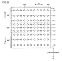
よって、図20に示すように、L−R方向(図中のD2方向)の温度センサ100の配置ピッチは一定とし、F−B方向(図中のD1方向)のみ、一次コイルユニット60から生じる磁界強度が最も強い領域から遠ざかる場合に、温度センサ100bの配置ピッチが広くなる構成を採用してもよい。
Therefore, as shown in FIG. 20, the arrangement pitch of the
また、図21に示すように、温度センサ100の配置ピッチは一定とし、一次コイルユニット60から生じる磁界強度が最も強い領域に位置する温度センサ100に対しては、検知範囲を拡大するために、一次側蓋部材64の一次コイルユニット60側の内面64rに最も面積の大きな、熱伝導性に優れた第1導電板110aを設け、この第1導電板110a上に温度センサ100を配置するとよい。したがって、図21に示す構成においては、導電板を含めた構成が温度センサを構成する。その結果、温度センサ(導電板)の配置間隔は、送電部56から生じる電磁界強度の強いところは、電磁界強度の弱いところに比べ狭い間隔となる。
Further, as shown in FIG. 21, the arrangement pitch of the
一次コイルユニット60から生じる磁界強度が最も強い領域から遠ざかる領域に位置する温度センサ100に対しては、第1導電板110aよりも面積の小さい第2導電板110b、さらに遠ざかる領域に位置する温度センサ100に対しては、この第2導電板110bよりも面積の小さい第3導電板110cを設けるようにするとよい。なお、導電板の面積は同じで、導電板の熱伝導率を変化させることで、図21に示す構成と同様の作用を得るようにすることも可能である。
For the
また、図21に示す構成では、すべての温度センサ100に同一性能のセンサを用いる場合について説明しているが、温度検知範囲の異なるセンサを組合せ、磁界強度が強い領域には、温度検知範囲の広いセンサを用い、磁界強度が弱い領域には、温度検知範囲の狭いセンサを用いるようにしてもよい。
In the configuration shown in FIG. 21, the case where the sensors having the same performance are used for all the
この構成によっても、一次コイルユニット60から生じる磁界強度が強い領域には、温度検知範囲が密となるように、一次側蓋部材64の一次コイルユニット60側の内面64rに温度センサ100が配置され、一次コイルユニット60から生じる磁界強度が強い領域から遠ざかるにしたがって、温度検知範囲が疎となるように、一次側蓋部材64の一次コイルユニット60側の内面64rに温度センサ100が配置されることとなる。
Even in this configuration, the
その結果、磁界強度が強い領域ほど、温度センサ100による検知範囲が密となり、小さい異物(ボタン電池(金属+電解液)、ライター(金属+可燃物))であっても、精度よく異物の検知が可能となる。その結果、磁界強度が高く、異物が高温になり易いところにおいては、高温となる異物検知を精度良く行なうことが可能となる。
As a result, the detection range by the
一方、磁界強度が弱い領域(異物が存在しても高温にはなり難い)では、温度センサ100の配置間隔が広くなるため、温度センサ100による検知範囲が疎となる。その結果、温度センサの配置によるコストの上昇を抑制することが可能になる。
On the other hand, in the region where the magnetic field strength is weak (it is difficult to reach a high temperature even if foreign matter is present), the arrangement interval of the
次に、図23から図26を参照して、温度センサ100の接続状態について説明する。図23は、温度センサ100の温度検知回路を示す図、図24は、PTCサーミスタの電圧−温度特性を示す図、図25は、NTCサーミスタの電圧−温度特性を示す図、図26は、温度センサの他の温度検知回路を示す図である。
Next, the connection state of the
図23を参照して、本実施の形態では、抵抗300、複数の温度センサ100が直列に接続されている。また、温度センサ100には、PTC(positive temperature coefficient)サーミスタを用いるとよい。PTCサーミスタは、温度の上昇により抵抗値が急峻に高くなる性質を有している。その結果、図24に示すように、図23の温度検知回路にPTCサーミスタを用いた場合、正常時の出力電圧P11に比べて、PTCサーミスタの温度が上昇する異常時には、急峻に出力電圧P12が高くなる。その結果、容易に過熱状態を検知することができる。
Referring to FIG. 23, in the present embodiment,
一方、NTC(negative temperature
coefficient)サーミスタは、温度の上昇により抵抗値が低くなる性質を有している。NTCサーミスタは、温度の上昇により抵抗値が一定に低くなる性質を有している。その結果、図25に示すように、図23の温度検知回路にNTCサーミスタを用いた場合、正常時の出力電圧P21に比べて、NTCサーミスタの温度が上昇する異常時には、出力電圧P22が低くなる。NTCサーミスタの場合には、温度上昇に略反比例して出力電圧が低下することから、過熱状態を観察する観点からは、PTCサーミスタを用いることが好ましい。On the other hand, NTC (negative temperature
The coefficient) thermistor has the property that the resistance value decreases as the temperature rises. The NTC thermistor has a property that its resistance value is constantly reduced as the temperature rises. As a result, as shown in FIG. 25, when the NTC thermistor is used in the temperature detection circuit of FIG. . In the case of an NTC thermistor, since the output voltage decreases approximately in inverse proportion to the temperature rise, it is preferable to use a PTC thermistor from the viewpoint of observing an overheated state.
また、NTCサーミスタを用いた場合には、温度測定のために「並列に」接続する必要がある。そのため、各々に基準抵抗と温度測定用の出力端子が必要となり、素子数の増大、配線の複雑化によりコストアップを招くことになるが、PTCサーミスタを用いた場合には、そのようなコストアップは生じない。 Further, when an NTC thermistor is used, it is necessary to connect “in parallel” for temperature measurement. For this reason, a reference resistor and an output terminal for temperature measurement are required for each, and the cost increases due to the increase in the number of elements and the complexity of the wiring. However, when a PTC thermistor is used, such a cost increase occurs. Does not occur.
上記のようにして得られた出力信号は、監視回路550に送られる。監視回路550の記憶部には、予め、温度センサ100が異常高温であるときの温度分布データを格納しておくことで、格納された温度分布データと、温度検知回路から得られる信号に基づいて、受電部20と送電部56との間に高温となる異物があるか否かを判断する。
The output signal obtained as described above is sent to the
監視回路550において高温となる異物があると判断された場合には、所定の出力信号S1が制御部55(図1参照)に出力され、送電装置50による電力の送電が中止される。また、送電中止信号が、送電装置50側のアンテナ61から電動車両10側のアンテナ49に送られることにより、電動車両10側に送電中止信号を送信するようにしてもよい。なお、監視回路550は、制御部55の内部に設けてもよい。
When it is determined in the
また、図26に示すように、一次側蓋部材64の一次コイルユニット60側の内面64rに複数の温度センサ100を配置する場合に、複数の温度センサ100を有する第1温度センサ群100Aと、複数の温度センサ100を有する第2温度センサ群100Bとに分け、第1温度センサ群100Aと第2温度センサ群100Bとを並列にして、論理回路(OR)回路(検知回路)600に第1温度センサ群100Aおよび第2温度センサ群100Bからの出力信号を出力するようにする。
Further, as shown in FIG. 26, when a plurality of
論理回路(OR)回路(検知回路)600においては、少なくもいずれか一方のセンサ群からの信号を入力した場合には、予め格納された、温度センサ100が異常高温であるときの温度分布データと、センサ群から得られる信号に基づいて、受電部20と送電部56との間に高温となる異物があるか否かを判断する。
In the logic circuit (OR) circuit (detection circuit) 600, when a signal from at least one of the sensor groups is input, temperature distribution data stored in advance when the
論理回路(検知回路)600において高温となる異物があると判断された場合には、所定の出力信号S2が制御部55に出力され、送電装置50による電力の送電が中止される。また、送電中止信号が、送電装置50側のアンテナ61から電動車両10側のアンテナ49に送られることにより、電動車両10側に送電中止信号を送信するようにしてもよい。なお、論理回路(検知回路)600は、制御部55の内部に設けてもよい。
When it is determined in the logic circuit (detection circuit) 600 that there is a foreign substance that becomes high in temperature, a predetermined output signal S2 is output to the
なお、上記説明においては、主として、複数の温度センサ100が、一次側蓋部材64の一次コイルユニット60側の内面64rに配置されることを前提として説明している。
In the above description, the description is mainly based on the assumption that the plurality of
しかし、図27に示すように、一次側蓋部材64ではなく、複数の温度センサ100が、二次側蓋部材29の二次コイルユニット24側の内面29rに設けられる場合であっても、上述した温度センサ100の配置および温度検知回路を適用することが可能である。
However, as shown in FIG. 27, even when the plurality of
二次側蓋部材29に温度センサ100を配置した場合には、温度検知回路から得られる信号は、車両ECU12に出力され、受電装置11による電力の受電が中止されるようにするとよい。また、受電中止信号が、電動車両10側のアンテナ49から送電装置50側のアンテナ61に送られることにより、外部給電装置51側に受電中止信号を送信するようにしてもよい。
When the
なお、温度検知の精度を高めるために、温度センサ100を一次側蓋部材64および二次側蓋部材29の両方に設ける構成を採用してもよい。また、第1温度センサ群100Aおよび第2温度センサ群100Bの2つの群だけでなく、3以上のセンサ群に分けてもよい。
In order to increase the accuracy of temperature detection, a configuration in which the
(受電部20の駆動機構30)
次に、図28から図32を参照して、二次側蓋部材29に温度センサ100を配置した場合に、受電部20を昇降可能に支持する駆動機構30について説明する。図28は、実施の形態における受電部20に設けられることが可能な駆動機構30を示す斜視図、図29は、図28中の矢印A方向から見た図、図30は、実施の形態における受電部20に設けられることが可能な駆動機構30の上昇状態を示す斜視図、図31は、実施の形態における受電部20に設けられることが可能な駆動機構30の途中状態を示す斜視図、図32は、実施の形態における受電部20に設けられることが可能な駆動機構30の下降状態を示す斜視図である。(Drive
Next, with reference to FIG. 28 to FIG. 32, the
図28に示すように、受電部20には、受電部20を送電部56に向けて近接するように移動させることと、受電部20を送電部56から離れるように移動させることとが可能な駆動機構30が設けられている。
As shown in FIG. 28, the
駆動機構30は、リンク機構31と、駆動部32と、付勢部材33と、保持装置89と、ストッパ35と、切替部36とを含む。リンク機構31は、支持部材37および支持部材38を含む。
The
支持部材37は、フロアパネル26などに回転可能に支持された回転シャフト40と、回転シャフト40の一端に形成された脚部41と、回転シャフト40の他方端に接続された脚部42とを含む。脚部41の下端部は、二次側筐体27の側面壁75に回転可能に接続されている。脚部42の下端部は、側面壁74に回転可能に接続されている。
The
支持部材38は、支持部材37と巻回軸線O1の延びる方向に間隔をあけて配置されている。支持部材38は、フロアパネル26などに回転可能に支持された回転シャフト45と、回転シャフト45の一端に接続された脚部46と、回転シャフト45の他端に接続された脚部48とを含む。脚部46の下端部は側面壁75に回転可能に接続されており、脚部48の下端部は、側面壁74に回転可能に接続されている。
The
駆動部32は、回転シャフト45の端部に設けられたギヤ80と、ギヤ80と噛み合うギヤ81と、ギヤ81を回転させるモータ82とを含む。
The
モータ82は、回転可能に設けられ、ギヤ81に接続されたロータ95と、このロータ95の周囲に設けられたステータ96と、ロータ95の回転角度を検知するエンコーダ97とを含む。
The
モータ82に電力が供給されると、ロータ95が回転する。ロータ95が回転すると、ギヤ81が回転し、ギヤ81と噛み合うギヤ80も回転する。ギヤ80は、回転シャフト45に固定されているため、回転シャフト45が回転する。回転シャフト45が回転することで、受電部20および二次側筐体27が移動する。このように、モータ82の駆動力は受電部20および二次側筐体27に伝達される。モータ82の回転方向によって、受電部20および二次側筐体27の上昇および下降が制御される。
When electric power is supplied to the
付勢部材33は、脚部46とフロアパネル26とに接続された弾性部材33aと、脚部48とフロアパネル26とに接続された弾性部材33bとを含む。
The biasing
なお、弾性部材33aの端部83は、脚部46に回転可能に接続されており、弾性部材33aの端部84は、フロアパネル26に回転可能に接続されている。弾性部材33bの端部85も脚部48に回転可能に接続されており、弾性部材33bの端部86もフロアパネル26に回転可能に接続されている。
Note that the
弾性部材33aの端部83は、脚部46の中央部よりも脚部46の下端部側に設けられている。弾性部材33aの端部84は、脚部46と回転シャフト45との接続部に対して、支持部材37と反対側に位置している。
The
弾性部材33bの端部85は、脚部48の中央部よりも脚部48の下端部側に設けられている。弾性部材33bの端部86は、回転シャフト45と脚部48との接続部に対して、支持部材37と反対側に位置している。
The
図28中の受電部20(破線で示す)および二次側筐体27は、受電部20が送電部56に向けて下降する前の初期状態における受電部20および二次側筐体27を示す。この初期状態に示す状態においては、弾性部材33aおよび弾性部材33bは、自然長の状態である。
The power receiving unit 20 (shown by a broken line) and the
後述の図31および図32中に示すように、受電部20および二次側筐体27が下方に向けて変位すると、弾性部材33aおよび弾性部材33bが伸びる。このため、弾性部材33aおよび弾性部材33bには、引張力が生じる。この引張力によって、受電部20および二次側筐体27は、初期状態となるように付勢される。
As shown in FIGS. 31 and 32 described later, when the
保持装置89は、フロアパネル26等に固定された装置本体88と、装置本体88から突出する突出量が調整される支持部材87とを含む。支持部材87は、初期状態における二次側筐体27の底面側(二次側蓋部材)を支持し、受電部20を電動車両10側に固定する。なお、端面壁73に穴部を形成し、この穴部に支持部材87を挿入するようにしてもよい。
The holding
ストッパ35は、脚部41の回角度を規制するストッパ片90およびストッパ片91を含み、受電部20および側面壁75が回転する範囲を規定する。
The
ストッパ片90は、脚部41,42と接触して、受電部20および二次側筐体27が電動車両10のフロアパネル26等と接触することを抑制する。
The
ストッパ片91は、脚部41,42と接触して、下方における受電部20および二次側筐体27の移動範囲を規制することで、地面に置かれた部材と接触することを抑制する。
The
切替部36は、回転シャフト45に固定されたギヤ92と、このギヤ92と係合するストッパ93とを含む。なお、ストッパ93は、図1に示す車両ECU12によってギヤ92と係合したり、ギヤ92との係合状態が解除されたりする。ストッパ93がギヤ92と係合することで、受電部20が下降する方向に回転シャフト45が回転することが規制された規制状態となる。具体的には、規制状態とは受電部20が送電部56から離れることを許容すると共に受電部20が送電部56に近づくことを抑制する状態である。
The switching
なお、ストッパ93とギヤ92との係合状態が解除されると、切替部36は、受電部20が上昇する方向に回転シャフト45が回転することと、受電部20が下方に下がるように回転シャフト45が回転することとを許容する許容状態となる。具体的には、許容状態とは、受電部20が送電部56から離れることを許容すると共に受電部20が送電部56に近づくことを許容する許容状態となる。
When the engagement state between the
図29は、切替部36を模式的に示す側面図であり、図28の矢印A方向から見たときの側面図である。この図29に示すように、切替部36は、回転シャフト45に固定されたギヤ92と、ギヤ92と選択的に係合するストッパ93と、駆動部110とを備える。
FIG. 29 is a side view schematically showing the switching
ギヤ92の周面には、複数の歯部99が間隔をあけて形成されている。ストッパ93は、軸部98に回転可能に設けられている。駆動部110は、ストッパ93を回転させる。駆動部110は、ストッパ93の先端部が歯部99と係合した状態と、ストッパ93の先端部がギヤ92から離れて、ストッパ93とギヤ92とが係合しない状態とを切り替える。
On the peripheral surface of the
なお、軸部98には、トーションバネ111などが設けられており、ストッパ93は、このトーションバネ111からの付勢力によって、ストッパ93の先端部がギヤ92の周面に押さえつけられる。
The
駆動部110は、トーションバネ111の付勢力に抗して、ストッパ93の先端部がギヤ92の周面から離れるように、ストッパ93を回転させることができる。なお、駆動部110の駆動は、可動機構制御部18によって制御されている。
The
回転方向Dr1は、受電部20および二次側筐体27が上昇する際に、回転シャフト45およびギヤ92が回転する方向であり、回転方向Dr2は、受電部20および二次側筐体27が下降する際に回転シャフト45およびギヤ92が回転する方向である。
The rotation direction Dr1 is a direction in which the
そして、ストッパ93がギヤ92と係合することで、回転方向Dr2にギヤ92が回転することが規制される。
Then, when the
その一方で、ストッパ93とギヤ92とが係合した状態においても、ギヤ92は回転方向Dr1に回転することが可能である。
On the other hand, even when the
図1において、調整部9は、バッテリ15から駆動機構30のモータ82に供給する電力量の調整をする。可動機構制御部18は、調整部9の駆動を制御する。
In FIG. 1, the
上記のように構成された受電部20が送電部56から電力を受電するときの動作について説明する。
An operation when the
受電部20が送電部56から電力を受電する際には、電動車両10は所定の位置に停車(駐車)する。図30は、電動車両10が停車したときにおける受電部20、二次側筐体27および駆動機構30を示す側面図である。
When the
この図30に示すように、二次側筐体27は、フロアパネル26に近接した状態で保持装置89によって支持されており、二次側筐体27は初期位置に固定されている。なお、この初期状態においては、付勢部材33は、自然長であり、付勢部材33は、受電部20および二次側筐体27に引張力などの力を加えていない状態である。
As shown in FIG. 30, the
そして、受電部20が非接触で電力を受電する際には、可動機構制御部18は、保持装置89を駆動して、支持部材87を二次側筐体27の下面から退避させる。
When the
そして、可動機構制御部18は、バッテリ15からモータ82に電力が供給されるように調整部9をONとする。
Then, the movable
モータ82に電力が供給されると、モータ82からの動力によって、図31に示すように、脚部46が回転シャフト45を中心に回転する。これにより、受電部20および二次側筐体27は、鉛直方向下方Dに向かうと共に、車両前進方向Fに向かうように移動する。
When electric power is supplied to the
この際、支持部材37も、支持部材38、受電部20および二次側筐体27の移動に追従するように移動する。なお、支持部材37は回転シャフト40を中心として回転する。
At this time, the
付勢部材33は、受電部20および二次側筐体27が移動することに伴って伸び、付勢部材33は、図30に示すように、二次側筐体27が初期状態となるように二次側筐体27に引張力を加える。モータ82は、当該引張力に抗して、二次側筐体27を移動させる。エンコーダ97は、モータ82のロータ95の回転角度を可動機構制御部18に送信している。
The urging
図32は、受電部20が送電部56から非接触で電力を受電するときにおける状態を示す側面図である。
FIG. 32 is a side view showing a state when the
この図32において、可動機構制御部18は、エンコーダ97からの情報に基づいて、二次側筐体27および受電部20の位置を把握している。そして、ロータ95の回転角度が、受電部20と送電部56とが対向する対向角度であると可動機構制御部18が判断すると、図29において、可動機構制御部18は、駆動部110を駆動させて、ストッパ93をギヤ92に係合させる。
In FIG. 32, the movable
これにより、ギヤ92および回転シャフト45の回転が停止して、受電部20および二次側筐体27の下降が停止する。なお、付勢部材33の引張力は、モータ82からの駆動力よりも小さいため、受電部20および二次側筐体27が上昇することが抑制されている。このようにして、受電部20および二次側筐体27の移動が停止する。すなわち、モータ82が受電部20および二次側筐体27を下降させる方向に駆動する一方で、ストッパ93がギヤ92に係合することで、受電部20および二次側筐体27の移動が止められており、モータ82の駆動力の方が付勢部材33の引張力よりも大きいため、受電部20および二次側筐体27が停止した状態が維持される。
Thereby, the rotation of the
図32において、破線で示す支持部材38は、初期状態における支持部材38の位置を示す。この初期状態における支持部材38を基準として支持部材38が回転した回転角度を回転角度θとする。
In FIG. 32, a
本実施の形態においては、回転角度θが45度以上100度以下の範囲で受電部20と送電部56と位置合わせを行う。
In the present embodiment, the
このような回転角度θの範囲においては、回転角度θの変化量に対して、鉛直方向上方Uおよび鉛直方向下方Dにおける受電部20の変位量よりも車両後進方向Bおよび車両前進方向F(水平方向)における受電部20の変化量の方が大きい。
In such a range of the rotation angle θ, the vehicle reverse direction B and the vehicle forward direction F (horizontal) with respect to the amount of change of the rotation angle θ, rather than the amount of displacement of the
このため、受電部20と送電部56とが相対的に車両後進方向Bまたは車両前進方向Fに位置ずれしたとしても、受電部20の鉛直方向の位置が大きく変化することを抑制しながら、受電部20と送電部56との水平方向の位置ずれを調整することができる。
For this reason, even if the
好ましくは、回転角度θが45度以上90度以下の範囲で、受電部20と送電部56との相対的な位置合わせを行う。
Preferably, relative positioning of the
このように、回転角度θが90度以下となるような範囲で行なうことで、受電部20と送電部56との位置合わせを行なう際に受電部20の移動範囲が小さくなり、受電部20が地面上に置かれた異物と衝突することを抑制することができる。
As described above, when the rotation angle θ is within a range of 90 degrees or less, when the
なお、この図32に示す例においては、回転角度θが略90度となる位置で受電部20と送電部56とが対向している。特に、回転角度θが90度の近傍においては、受電部20および二次側筐体27は、回転角度θの変化量に対して、鉛直方向上方Uおよび鉛直方向下方Dの変位量よりも車両後進方向Bおよび車両前進方向F(水平方向)の変位量の方が大きい。
In the example shown in FIG. 32, the
このため、受電部20と送電部56とが相対的に車両後進方向Bまたは車両前進方向Fに位置ずれしたとしても、受電部20の鉛直方向の位置が大きく変化することを抑制しながら、受電部20と送電部56との水平方向の位置ずれを調整することができる。
For this reason, even if the
(送電部56および受電部20の他の形態)
上述の実施の形態では、図4および図6に示したように、送電部56の一次コイルユニット60、および受電部20の二次コイルユニット24には、ソレノイド型のコイルを用いた場合について説明した。しかし、後述するように、環状型のコイルを用いることも可能である。(Other forms of
In the above-described embodiment, as shown in FIGS. 4 and 6, a case where a solenoid type coil is used for the
図33に、受電部20の二次コイルユニット24に環状型のコイルを用いた場合を図示する。この受電部20は、環状型の二次コイルユニット24と、この二次コイルユニット24に接続された二次キャパシタ23とを含む。二次コイルユニット24は、円筒形状コア21と、この円筒形状コア21の周面に巻回された環状の二次コイル(第2コイル)22とを含む。本形態においても、図4に示す受電部20と同様に、二次キャパシタ23は、必須の構成ではない。二次コイル22は、整流器13(図1参照)に接続されている。
FIG. 33 illustrates a case where an annular coil is used for the
また、受電部20は、二次側筐体27に収容されている。二次側筐体27は、開口部を有する有底筒状の二次側シールド28と、二次側シールド28の開口部を閉塞するように配置された平板円形状の二次側蓋部材29とを備える。二次側シールド28は、フロアパネル26(図3参照)と対向する天板部28aと、天板部から鉛直方向下方Dに垂れ下がる環状の周壁部28bとを含む。二次側シールド28は、たとえば、銅などの金属材料から形成されている。
In addition, the
二次側蓋部材29は、二次側シールド28の開口部を閉塞するように平板円形状に形成されており、たとえば、樹脂材料などから形成されている。
The
上記構成を有する環状型の二次コイルユニット24に温度センサを用いる場合、二次コイルユニット24の磁界強度は、環状の二次コイル22の中心部領域が最も強く、半径方向の外側に向かうに従って磁界強度は弱くなる。そこで、二次側蓋部材29の二次コイルユニット24側の内面29rに温度センサ100を配置する場合には、二次側蓋部材29の中心部C1に対向する領域に温度センサ100を配置して、半径方向の外側に向かうにしたがって、温度センサ100の配置間隔が大きくなるように複数の温度センサ100を配置する。
When a temperature sensor is used for the annular
これによっても、二次コイルユニット24から生じる磁界強度が最も強い領域には、温度検知範囲が最も密になるように、二次側蓋部材29の二次コイルユニット24側の内面29rに温度センサ100を配置し、二次コイルユニット24から生じる磁界強度が最も強い領域から遠ざかるにしたがって、温度検知範囲が疎になるように、二次側蓋部材29の二次コイルユニット24側の内面29rに温度センサ100を配置することとなる。その結果、ソレノイド型のコイルを用いた場合と同様の作用効果を得ることができる。
Also in this manner, in the region where the magnetic field intensity generated from the
図34に、送電部56の一次コイルユニット60に環状型のコイルを用いた場合を図示する。この送電部56は、環状型の一次コイルユニット60と、この一次コイルユニット60に接続された一次キャパシタ59とを含む。一次コイルユニット60は、円筒形状コア57と、この円筒形状コア57に巻回された環状の一次コイル(第1コイル)58とを含む。本形態においても、図6に示す送電部56と同様に、一次キャパシタ59は、必須の構成ではない。
FIG. 34 illustrates a case where an annular coil is used for the
また、送電部56は、一次側筐体62に収容されている。一次側筐体62は、開口部を有する有底筒状の一次側シールド63と、一次側シールド63の開口部を閉塞するように配置された平板円形状の一次側蓋部材64とを備える。一次側シールド63は、駐車スペース52側に位置する天板部63aと、天板部63aから鉛直方向上方Uに起立する環状の周壁部63bとを含む。一次側シールド63は、たとえば、銅などの金属材料から形成されている。
In addition, the
一次側蓋部材64は、一次側シールド63の開口部を閉塞するように平板円形状に形成されており、たとえば、樹脂材料などから形成されている。
The primary
上記構成を有する環状型の一次コイルユニット60に温度センサを用いる場合、一次コイルユニット60の磁界強度は、環状の一次コイル58の中心部が最も強く、半径方向の外側に向かうに従って磁界強度は弱くなる。そこで、一次側蓋部材64の一次コイルユニット60側の内面64rに温度センサ100を配置する場合には、一次側蓋部材64の中心部C1に温度センサ100を配置して、半径方向の外側に向かうにしたがって、温度センサ100の配置間隔が大きくなるように複数の温度センサ100を配置する。
When a temperature sensor is used for the annular
これによっても、一次コイルユニット60から生じる磁界強度が最も強い領域には、温度検知範囲が最も密になるように、一次側蓋部材64の一次コイルユニット60側の内面64rに温度センサ100を配置し、一次コイルユニット60から生じる磁界強度が最も強い領域から遠ざかるにしたがって、温度検知範囲が疎になるように、一次側蓋部材64の一次コイルユニット60側の内面64rに温度センサ100を配置することとなる。その結果、ソレノイド型のコイルを用いた場合と同様の作用効果を得ることができる。
Also in this manner, the
次に、図2、図35から図38を用いて、受電部20と送電部56との間の電力伝送の原理について説明する。
Next, the principle of power transmission between the
本実施の形態に係る電力伝送システムにおいては、図2に示すように、送電部56の固有周波数と、受電部20の固有周波数との差は、受電部20または送電部56の固有周波数の10%以下である。このような範囲に各送電部56および受電部20の固有周波数を設定することで、電力伝送効率を高めることができる。その一方で、固有周波数の差が受電部20または送電部56の固有周波数の10%よりも大きくなると、電力伝送効率が10%より小さくなり、バッテリ15の充電時間が長くなるなどの弊害が生じる。
In the power transmission system according to the present embodiment, as shown in FIG. 2, the difference between the natural frequency of
ここで、送電部56の固有周波数とは、一次キャパシタ59が設けられていない場合には、一次コイル58のインダクタンスと、一次コイル58のキャパシタンスとから形成された電気回路が自由振動する場合の振動周波数を意味する。一次キャパシタ59が設けられた場合には、送電部56の固有周波数とは、一次コイル58および一次キャパシタ59のキャパシタンスと、一次コイル58のインダクタンスとによって形成された電気回路が自由振動する場合の振動周波数を意味する。上記電気回路において、制動力および電気抵抗をゼロもしくは実質的にゼロとしたときの固有周波数は、送電部56の共振周波数とも呼ばれる。
Here, the natural frequency of the
同様に、受電部20の固有周波数とは、二次キャパシタ23が設けられていない場合には、二次コイル22のインダクタンスと、二次コイル22のキャパシタンスとから形成された電気回路が自由振動する場合の振動周波数を意味する。二次キャパシタ23が設けられた場合には、受電部20の固有周波数とは、二次コイル22および二次キャパシタ23のキャパシタンスと、二次コイル22のインダクタンスとによって形成された電気回路が自由振動する場合の振動周波数を意味する。上記電気回路において、制動力および電気抵抗をゼロもしくは実質的にゼロとしたときの固有周波数は、受電部20の共振周波数とも呼ばれる。
Similarly, the natural frequency of the
図35および図36を用いて、固有周波数の差と電力伝送効率との関係とを解析したシミュレーション結果について説明する。図35は、電力伝送システムのシミュレーションモデルを示す図である。電力伝送システムは、送電装置190と、受電装置191とを備え、送電装置190は、コイル192(電磁誘導コイル)と、送電部193とを含む。送電部193は、コイル194(1次コイル)と、コイル194に設けられたキャパシタ195とを含む。
A simulation result obtained by analyzing the relationship between the natural frequency difference and the power transmission efficiency will be described with reference to FIGS. 35 and 36. FIG. 35 is a diagram illustrating a simulation model of the power transmission system. The power transmission system includes a
受電装置191は、受電部196と、コイル197(電磁誘導コイル)とを備える。受電部196は、コイル199とこのコイル199(2次コイル)に接続されたキャパシタ198とを含む。
The
コイル194のインダクタンスをインダクタンスLtとし、キャパシタ195のキャパシタンスをキャパシタンスC1とする。コイル199のインダクタンスをインダクタンスLrとし、キャパシタ198のキャパシタンスをキャパシタンスC2とする。このように各パラメータを設定すると、送電部193の固有周波数f1は、下記の式(1)によって示され、受電部196の固有周波数f2は、下記の式(2)によって示される。
The inductance of the
f1=1/{2π(Lt×C1)1/2}・・・(1)
f2=1/{2π(Lr×C2)1/2}・・・(2)
ここで、インダクタンスLrおよびキャパシタンスC1,C2を固定して、インダクタンスLtのみを変化させた場合において、送電部193および受電部196の固有周波数のズレと、電力伝送効率との関係を図36に示す。なお、このシミュレーションにおいては、コイル194およびコイル199の相対的な位置関係は固定した状態であって、さらに、送電部193に供給される電流の周波数は一定である。f1 = 1 / {2π (Lt × C1) 1/2 } (1)
f2 = 1 / {2π (Lr × C2) 1/2 } (2)
Here, when the inductance Lr and the capacitances C1 and C2 are fixed and only the inductance Lt is changed, the relationship between the deviation of the natural frequency of the
図36に示すグラフのうち、横軸は、固有周波数のズレ(%)を示し、縦軸は、一定周波数での伝送効率(%)を示す。固有周波数のズレ(%)は、下記式(3)によって示される。 In the graph shown in FIG. 36, the horizontal axis indicates the deviation (%) of the natural frequency, and the vertical axis indicates the transmission efficiency (%) at a constant frequency. The deviation (%) in the natural frequency is expressed by the following equation (3).
(固有周波数のズレ)={(f1−f2)/f2}×100(%)・・・(3)
図36からも明らかなように、固有周波数のズレ(%)が±0%の場合には、電力伝送効率は、100%近くとなる。固有周波数のズレ(%)が±5%の場合には、電力伝送効率は、40%となる。固有周波数のズレ(%)が±10%の場合には、電力伝送効率は、10%となる。固有周波数のズレ(%)が±15%の場合には、電力伝送効率は、5%となる。すなわち、固有周波数のズレ(%)の絶対値(固有周波数の差)が、受電部196の固有周波数の10%以下の範囲となるように各送電部および受電部の固有周波数を設定することで電力伝送効率を高めることができることがわかる。さらに、固有周波数のズレ(%)の絶対値が受電部196の固有周波数の5%以下となるように、各送電部および受電部の固有周波数を設定することで電力伝送効率をより高めることができることがわかる。なお、シミュレーションソフトしては、電磁界解析ソフトウェア(JMAG(登録商標):株式会社JSOL製)を採用している。(Deviation of natural frequency) = {(f1−f2) / f2} × 100 (%) (3)
As is clear from FIG. 36, when the deviation (%) in the natural frequency is ± 0%, the power transmission efficiency is close to 100%. When the deviation (%) in natural frequency is ± 5%, the power transmission efficiency is 40%. When the deviation (%) of the natural frequency is ± 10%, the power transmission efficiency is 10%. When the deviation (%) in natural frequency is ± 15%, the power transmission efficiency is 5%. That is, by setting the natural frequency of each power transmission unit and the power reception unit so that the absolute value (difference in natural frequency) of the deviation (%) of the natural frequency is within a range of 10% or less of the natural frequency of the
次に、本実施の形態に係る電力伝送システムの動作について説明する。
図1において、一次コイル58には、高周波電力ドライバ54から交流電力が供給される。この際、一次コイル58を流れる交流電流の周波数が特定の周波数となるように電力が供給されている。Next, the operation of the power transmission system according to the present embodiment will be described.
In FIG. 1, AC power is supplied to the
一次コイル58に特定の周波数の電流が流れると、一次コイル58の周囲には特定の周波数で振動する電磁界が形成される。
When a current having a specific frequency flows through the
二次コイル22は、一次コイル58から所定範囲内に配置されており、二次コイル22は一次コイル58の周囲に形成された電磁界から電力を受け取る。
The
本実施の形態においては、二次コイル22および一次コイル58は、所謂、ヘリカルコイルが採用されている。このため、一次コイル58の周囲には、特定の周波数で振動する磁界および電界が形成され、二次コイル22は主に当該磁界から電力を受け取る。
In the present embodiment, so-called helical coils are employed for the
ここで、一次コイル58の周囲に形成される特定の周波数の磁界について説明する。「特定の周波数の磁界」は、典型的には、電力伝送効率と一次コイル58に供給される電流の周波数と関連性を有する。そこで、まず、電力伝送効率と、一次コイル58に供給される電流の周波数との関係について説明する。一次コイル58から二次コイル22に電力を伝送するときの電力伝送効率は、一次コイル58および二次コイル22の間の距離などの様々な要因よって変化する。たとえば、送電部56および受電部20の固有周波数(共振周波数)を固有周波数f0とし、一次コイル58に供給される電流の周波数を周波数f3とし、二次コイル22および一次コイル58の間のエアギャップをエアギャップAGとする。
Here, a magnetic field having a specific frequency formed around the
図37は、固有周波数f0を固定した状態で、エアギャップAGを変化させたときの電力伝送効率と、一次コイル58に供給される電流の周波数f3との関係を示すグラフである。
FIG. 37 is a graph showing the relationship between the power transmission efficiency when the air gap AG is changed and the frequency f3 of the current supplied to the
図37に示すグラフにおいて、横軸は、一次コイル58に供給する電流の周波数f3を示し、縦軸は、電力伝送効率(%)を示す。効率曲線L1は、エアギャップAGが小さいときの電力伝送効率と、一次コイル58に供給する電流の周波数f3との関係を模式的に示す。この効率曲線L1に示すように、エアギャップAGが小さい場合には、電力伝送効率のピークは周波数f4,f5(f4<f5)において生じる。エアギャップAGを大きくすると、電力伝送効率が高くなるときの2つのピークは、互いに近づくように変化する。そして、効率曲線L2に示すように、エアギャップAGを所定距離よりも大きくすると、電力伝送効率のピークは1つとなり、一次コイル58に供給する電流の周波数が周波数f6のときに電力伝送効率がピークとなる。エアギャップAGを効率曲線L2の状態よりもさらに大きくすると、効率曲線L3に示すように電力伝送効率のピークが小さくなる。
In the graph shown in FIG. 37, the horizontal axis indicates the frequency f3 of the current supplied to the
たとえば、電力伝送効率の向上を図るための手法として次のような第1の手法が考えられる。第1の手法としては、図1に示す一次コイル58に供給する電流の周波数を一定として、エアギャップAGにあわせて、一次キャパシタ59や二次キャパシタ23のキャパシタンスを変化させることで、送電部56と受電部20との間での電力伝送効率の特性を変化させる手法が挙げられる。具体的には、一次コイル58に供給される電流の周波数を一定とした状態で、電力伝送効率がピークとなるように、一次キャパシタ59および二次キャパシタ23のキャパシタンスを調整する。この手法では、エアギャップAGの大きさに関係なく、一次コイル58および二次コイル22に流れる電流の周波数は一定である。なお、電力伝送効率の特性を変化させる手法としては、送電装置50と高周波電力ドライバ54との間に設けられた整合器を利用する手法や、コンバータ14を利用する手法などを採用することもできる。
For example, the following first method can be considered as a method for improving the power transmission efficiency. As a first technique, the frequency of the current supplied to the
また、第2の手法としては、エアギャップAGの大きさに基づいて、一次コイル58に供給する電流の周波数を調整する手法である。たとえば、図37において、電力伝送特性が効率曲線L1となる場合には、一次コイル58には周波数が周波数f4または周波数f5の電流を一次コイル58に供給する。そして、周波数特性が効率曲線L2,L3となる場合には、周波数が周波数f6の電流を一次コイル58に供給する。この場合では、エアギャップAGの大きさに合わせて一次コイル58および二次コイル22に流れる電流の周波数を変化させることになる。
The second method is a method of adjusting the frequency of the current supplied to the
第1の手法では、一次コイル58を流れる電流の周波数は、固定された一定の周波数となり、第2の手法では、一次コイル58を流れる周波数は、エアギャップAGによって適宜変化する周波数となる。第1の手法や第2の手法などによって、電力伝送効率が高くなるように設定された特定の周波数の電流が一次コイル58に供給される。一次コイル58に特定の周波数の電流が流れることで、一次コイル58の周囲には、特定の周波数で振動する磁界(電磁界)が形成される。
In the first method, the frequency of the current flowing through the
受電部20は、受電部20と送電部56の間に形成され、かつ特定の周波数で振動する磁界および特定の周波数で振動する電界の少なくとも一方を通じて送電部56から電力を受電している。したがって、「特定の周波数で振動する磁界」は、必ずしも固定された周波数の磁界とは限らず、「特定の周波数で振動する電界」も、必ずしも固定された周波数の電界とは限らない。
The
なお、上記の例では、エアギャップAGに着目して、一次コイル58に供給する電流の周波数を設定するようにしているが、電力伝送効率は、一次コイル58および二次コイル22の水平方向のずれ等のように他の要因によっても変化するものであり、当該他の要因に基づいて、一次コイル58に供給する電流の周波数を調整する場合がある。
In the above example, focusing on the air gap AG, the frequency of the current supplied to the
なお共鳴コイルとしてヘリカルコイルを採用した例について説明したが、共鳴コイルとして、メアンダラインなどのアンテナなどを採用した場合には、一次コイル58に特定の周波数の電流が流れることで、特定の周波数の電界が一次コイル58の周囲に形成される。そして、この電界をとおして、送電部56と受電部20との間で電力伝送が行われる。
In addition, although the example which employ | adopted the helical coil as a resonance coil was demonstrated, when antennas, such as a meander line, are employ | adopted as a resonance coil, the electric current of a specific frequency flows into the
本実施の形態に係る電力伝送システムにおいては、電磁界の「静電磁界」が支配的な近接場(エバネッセント場)を利用することで、送電および受電効率の向上が図られている。図38は、電流源または磁流源からの距離と電磁界の強度との関係を示した図である。図38を参照して、電磁界は3つの成分から成る。曲線k1は、波源からの距離に反比例した成分であり、「輻射電磁界」と称される。曲線k2は、波源からの距離の2乗に反比例した成分であり、「誘導電磁界」と称される。また、曲線k3は、波源からの距離の3乗に反比例した成分であり、「静電磁界」と称される。なお、電磁界の波長を「λ」とすると、「輻射電磁界」と「誘導電磁界」と「静電磁界」との強さが略等しくなる距離は、λ/2πとあらわすことができる。 In the power transmission system according to the present embodiment, the efficiency of power transmission and power reception is improved by using a near field (evanescent field) in which the “electrostatic magnetic field” of the electromagnetic field is dominant. FIG. 38 is a diagram showing the relationship between the distance from the current source or the magnetic current source and the intensity of the electromagnetic field. Referring to FIG. 38, the electromagnetic field is composed of three components. The curve k1 is a component that is inversely proportional to the distance from the wave source, and is referred to as a “radiated electromagnetic field”. A curve k2 is a component inversely proportional to the square of the distance from the wave source, and is referred to as an “induction electromagnetic field”. The curve k3 is a component inversely proportional to the cube of the distance from the wave source, and is referred to as an “electrostatic magnetic field”. When the wavelength of the electromagnetic field is “λ”, the distance at which the “radiant electromagnetic field”, the “induction electromagnetic field”, and the “electrostatic magnetic field” have substantially the same strength can be expressed as λ / 2π.
「静電磁界」は、波源からの距離とともに急激に電磁波の強度が減少する領域であり、本実施の形態に係る電力伝送システムでは、この「静電磁界」が支配的な近接場(エバネッセント場)を利用してエネルギー(電力)の伝送が行なわれる。すなわち、「静電磁界」が支配的な近接場において、近接する固有周波数を有する送電部56および受電部20(たとえば一対のLC共振コイル)を共鳴させることにより、送電部56から他方の受電部20へエネルギー(電力)を伝送する。この「静電磁界」は遠方にエネルギーを伝播しないので、遠方までエネルギーを伝播する「輻射電磁界」によってエネルギー(電力)を伝送する電磁波に比べて、共鳴法は、より少ないエネルギー損失で送電することができる。
The “electrostatic magnetic field” is a region where the intensity of electromagnetic waves suddenly decreases with the distance from the wave source. In the power transmission system according to the present embodiment, this “electrostatic magnetic field” is a dominant near field (evanescent field). ) Is used to transmit energy (electric power). That is, in the near field where the “electrostatic magnetic field” is dominant, by resonating the
このような受電部と送電部との間に形成される電磁場は、たとえば、近接場共振(共鳴)結合場という場合がある。送電部と受電部との間の結合係数κは、たとえば、0.3以下程度であり、好ましくは、0.1以下である。結合係数κとしては、0.1〜0.3程度の範囲も採用することができる。結合係数κは、このような値に限定されるものでなく、電力伝送が良好となる種々の値をとり得る。 Such an electromagnetic field formed between the power reception unit and the power transmission unit may be referred to as a near-field resonance (resonance) coupling field, for example. The coupling coefficient κ between the power transmission unit and the power reception unit is, for example, about 0.3 or less, and preferably 0.1 or less. As the coupling coefficient κ, a range of about 0.1 to 0.3 can also be employed. The coupling coefficient κ is not limited to such a value, and may take various values that improve power transmission.
本実施の形態の電力伝送における送電部56と受電部20との結合を、たとえば、「磁気共鳴結合」、「磁界(磁場)共鳴結合」、「磁場共振(共鳴)結合」、「近接場共振(共鳴)結合」、「電磁界(電磁場)共振結合」または「電界(電場)共振結合」という。
For example, “magnetic resonance coupling”, “magnetic field (magnetic field) resonance coupling”, “magnetic field resonance (resonance) coupling”, “near-field resonance” may be used as the coupling between the
「電磁界(電磁場)共振結合」は、「磁気共鳴結合」、「磁界(磁場)共鳴結合」、「電界(電場)共振結合」のいずれも含む結合を意味する。 The “electromagnetic field (electromagnetic field) resonance coupling” means a coupling including any of “magnetic resonance coupling”, “magnetic field (magnetic field) resonance coupling”, and “electric field (electric field) resonance coupling”.
本明細書中で説明した送電部56の一次コイル58と受電部20の二次コイル22とは、コイル形状のアンテナが採用されているため、送電部56と受電部20とは主に、磁界によって結合しており、送電部56と受電部20とは、「磁気共鳴結合」または「磁界(磁場)共鳴結合」している。
Since the coil-shaped antenna is adopted for the
なお、一次コイル58および二次コイル22として、たとえば、メアンダラインなどのアンテナを採用することも可能であり、この場合には、送電部56と受電部20とは主に、電界によって結合している。このときには、送電部56と受電部20とは、「電界(電場)共振結合」している。このように、本実施の形態においては、受電部20と送電部56との間で非接触で電力伝送をしている。このように、非接触で電力伝送する際には、受電部20と送電部56との間には、主に、磁界が形成される。
For example, an antenna such as a meander line can be used as the
なお、上記実施の形態においては、送電部56から受電部20に電力を送電する場合について説明したが、受電部20から送電部56に電力を送電する場合においても、同様に、受電部20と送電部56との間に異物がある状態で電力送電されることを抑制することができる。
In addition, in the said embodiment, although the case where electric power was transmitted from the
今回開示された実施の形態はすべての点で例示であって制限的なものではないと考えられるべきである。本発明の範囲は請求の範囲によって示され、請求の範囲と均等の意味および範囲内でのすべての変更が含まれることが意図される。さらに、上記数値などは、例示であり、上記数値および範囲にかぎられない。 The embodiment disclosed this time should be considered as illustrative in all points and not restrictive. The scope of the present invention is defined by the terms of the claims, and is intended to include any modifications within the scope and meaning equivalent to the terms of the claims. Furthermore, the above numerical values are examples, and are not limited to the above numerical values and ranges.
9 調整部、10 電動車両、10A 車両本体、11,191 受電装置、13 整流器、14 コンバータ、15 バッテリ、16 パワーコントロールユニット、17 モータユニット、18 可動機構制御部、19B 後輪、19BL 左後輪、19BR 右後輪、19F 前輪、19FL 左前輪、19FR 右前輪、20,196 受電部、21 二次フェライトコア(円筒形状コア)、22 二次コイル、22a 第1端部、22b 第2端部、23 二次キャパシタ、24 二次コイルユニット、25 底面、26 フロアパネル、27 二次側筐体、28 二次側シールド、28a,63a 天板部、28b,63b 周壁部、29 二次側蓋部材、29r、64r 内面、30 駆動機構、31 リンク機構、32,110 駆動部、33 付勢部材、34L 左側縁部、33a,33b 弾性部材、34B 後縁部、34F 前縁部、34R 右側縁部、35,93 ストッパ、36 切替部、37,38,87 支持部材、40,45 回転シャフト、41,42,46,48 脚部、47 エンジン、49,61 アンテナ、50,190 送電装置、51 外部給電装置、52 駐車スペース、53 交流電源、54 高周波電力ドライバ、55 制御部、56,193 送電部、57 一次フェライトコア、58 一次コイル、59 一次キャパシタ、60 一次コイルユニット、62 一次側筐体、63 一次側シールド、64 一次側蓋部材、64C 領域、66L 左側後辺部、66R 右側後辺部、73 端面壁、74,75 側面壁、80,81,92 ギヤ、82 モータ、83,84,85,86 端部、88 装置本体、89 保持装置、90,91 ストッパ片、95 ロータ、96 ステータ、97 エンコーダ、98 軸部、99 歯部、100,100a,100b,100c 温度センサ、100A 第1温度センサ群、100B 第2温度センサ群、110a 第1導電板、110b 第2導電板、110c 第3導電板、111 トーションバネ、192,194,197,199 コイル、195,198 キャパシタ、300 抵抗、500 板、550 監視回路、600 論理回路(検知回路)。 DESCRIPTION OF SYMBOLS 9 Adjustment part, 10 Electric vehicle, 10A Vehicle main body, 11,191 Power receiving device, 13 Rectifier, 14 Converter, 15 Battery, 16 Power control unit, 17 Motor unit, 18 Movable mechanism control part, 19B Rear wheel, 19BL Left rear wheel , 19BR Right rear wheel, 19F Front wheel, 19FL Left front wheel, 19FR Right front wheel, 20,196 Power receiving unit, 21 Secondary ferrite core (cylindrical core), 22 Secondary coil, 22a First end, 22b Second end , 23 Secondary capacitor, 24 Secondary coil unit, 25 Bottom, 26 Floor panel, 27 Secondary casing, 28 Secondary shield, 28a, 63a Top plate, 28b, 63b Perimeter wall, 29 Secondary lid Member, 29r, 64r inner surface, 30 drive mechanism, 31 link mechanism, 32, 110 drive unit, 33 biasing Member, 34L Left edge, 33a, 33b Elastic member, 34B Rear edge, 34F Front edge, 34R Right edge, 35, 93 Stopper, 36 Switching portion, 37, 38, 87 Support member, 40, 45 Rotating shaft , 41, 42, 46, 48 Leg, 47 Engine, 49, 61 Antenna, 50, 190 Power transmission device, 51 External power supply device, 52 Parking space, 53 AC power supply, 54 High frequency power driver, 55 Control unit, 56, 193 Power transmission section, 57 Primary ferrite core, 58 Primary coil, 59 Primary capacitor, 60 Primary coil unit, 62 Primary casing, 63 Primary shield, 64 Primary lid member, 64C region, 66L Left rear side, 66R Right rear Side, 73 End wall, 74, 75 Side wall, 80, 81, 92 Gear, 82 Motor, 83, 84 85, 86 End, 88 Device body, 89 Holding device, 90, 91 Stopper piece, 95 Rotor, 96 Stator, 97 Encoder, 98 Shaft, 99 Teeth, 100, 100a, 100b, 100c Temperature sensor, 100A 1st Temperature sensor group, 100B second temperature sensor group, 110a first conductive plate, 110b second conductive plate, 110c third conductive plate, 111 torsion spring, 192, 194, 197, 199 coil, 195, 198 capacitor, 300 resistance, 500 plates, 550 monitoring circuit, 600 logic circuit (detection circuit).
Claims (19)
前記受電部を内部に収容する筐体と、を備え、
前記筐体は、前記送電部側に位置し、磁界の通過が可能な蓋部材と、
前記蓋部材に複数個配置され、前記送電部と前記受電部との間に位置する異物の温度を検知する温度センサと、を含み、
前記温度センサの配置間隔は、前記受電部から生じる電磁界強度の強いところは、電磁界強度の弱いところに比べ狭い間隔であり、
前記受電部は、
コアと、巻回軸線の周囲を取り囲むように前記コアの周面に巻回されたコイルと、を有し、
前記温度センサは、前記コイルの巻回される方向に沿って配置されている、受電装置。 A power receiving unit that receives power in a non-contact manner from a power transmitting unit provided outside;
A housing that houses the power receiving unit therein,
The housing is located on the power transmission unit side and is capable of passing a magnetic field; and
A plurality of the lid members, and a temperature sensor for detecting a temperature of a foreign object located between the power transmission unit and the power reception unit,
Arrangement interval of the temperature sensor, where strong electromagnetic field intensity generated from the power receiving unit, Ri closely spaced der than at weak electromagnetic field intensity,
The power receiving unit
A core and a coil wound around the circumference of the core so as to surround the winding axis;
The temperature sensor is a power receiving device arranged along a direction in which the coil is wound .
前記コイルユニットは、
板状のコアと、
前記コアの周面において、巻回軸線の周囲を取り囲むように巻き付けられるコイルと、を有し、
前記巻回軸線に対して交差する方向において、前記巻回軸線と交差する前記コイルの端部近傍の前記コアが露出する領域に、前記電磁界強度が強いところが位置する、請求項1に記載の受電装置。 The power receiving unit includes a solenoid type coil unit,
The coil unit is
A plate-shaped core;
A coil wound around the circumference of the core so as to surround the winding axis;
The direction where the said electromagnetic field strength is strong is located in the area | region where the said core of the edge part vicinity which cross | intersects the said winding axis is exposed in the direction which cross | intersects the said winding axis. Power receiving device.
前記コイルユニットは、
円筒形状のコアと、
前記コアの周面に巻回された環状のコイルと、を有し、
前記コイルユニットの電磁界強度は、前記コイルの中心部領域に、前記電磁界強度が強いところが位置する、請求項1に記載の受電装置。 The power receiving unit includes an annular coil unit,
The coil unit is
A cylindrical core;
An annular coil wound around the peripheral surface of the core,
2. The power receiving device according to claim 1, wherein the electromagnetic field intensity of the coil unit is located in a central region of the coil where the electromagnetic field intensity is strong.
いずれか一つのセンサ群に含まれる前記PTCサーミスタが所定の温度以上の温度を検知した場合に、検知信号を出力する検知回路を有する、請求項5に記載の受電装置。 The plurality of PTC thermistors have two or more sensor groups in which the plurality of PTC thermistors are connected in series,
The power receiving device according to claim 5, further comprising: a detection circuit that outputs a detection signal when the PTC thermistor included in any one of the sensor groups detects a temperature equal to or higher than a predetermined temperature.
前記受電部には、前記受電部を前記送電部に向けて近接するように移動させることと、前記受電部を前記送電部から離れるように移動させることとが可能な駆動機構が設けられている、請求項1に記載の受電装置。 The power receiving unit is mounted on a vehicle,
The power receiving unit is provided with a drive mechanism that can move the power receiving unit toward the power transmitting unit and move the power receiving unit away from the power transmitting unit. The power receiving device according to claim 1.
前記送電部を内部に収容する筐体と、を備え、
前記筐体は、前記受電部側に位置し、電磁界の通過が可能な蓋部材と、
前記蓋部材に複数個配置され、前記送電部と前記受電部との間に位置する異物の温度を検知する温度センサと、を含み、
前記温度センサの配置間隔は、前記送電部から生じる電磁界強度の強いところは、電磁界強度の弱いところに比べ狭い間隔であり、
前記送電部は、
コアと、巻回軸線の周囲を取り囲むように前記コアの周面に巻回されたコイルと、を有し、
前記温度センサは、前記コイルの巻回される方向に沿って配置されている、送電装置。 A power transmission unit that transmits power in a contactless manner to a power reception unit mounted on the vehicle;
A housing that houses the power transmission unit therein,
The housing is located on the power receiving unit side, and a lid member capable of passing an electromagnetic field;
A plurality of the lid members, and a temperature sensor for detecting a temperature of a foreign object located between the power transmission unit and the power reception unit,
Arrangement interval of the temperature sensor, where strong electromagnetic field intensity generated from the power transmission unit, Ri closely spaced der than at weak electromagnetic field intensity,
The power transmission unit
A core and a coil wound around the circumference of the core so as to surround the winding axis;
The temperature sensor is a power transmission device arranged along a direction in which the coil is wound .
前記コイルユニットは、
板状のコアと、
前記コアの周面において、巻回軸線の周囲を取り囲むように巻き付けられるコイルと、を有し、
前記巻回軸線に対して交差する方向において、前記巻回軸線と交差する前記コイルの端部近傍の前記コアが露出する領域に、前記電磁界強度が強いところが位置する、請求項11に記載の送電装置。 The power transmission unit includes a solenoid type coil unit,
The coil unit is
A plate-shaped core;
A coil wound around the circumference of the core so as to surround the winding axis;
The direction where the electromagnetic field strength is strong is located in a region where the core is exposed near an end of the coil that intersects the winding axis in a direction intersecting the winding axis. Power transmission device.
前記コイルユニットは、
円筒形状のコアと、
前記コアの周面に巻回された環状のコイルと、を有し、
前記コイルユニットの電磁界強度は、前記コイルの中心部領域に、前記電磁界強度が強いところが位置する、請求項11に記載の送電装置。 The power transmission unit includes an annular coil unit,
The coil unit is
A cylindrical core;
An annular coil wound around the peripheral surface of the core,
The power transmission device according to claim 11, wherein the electromagnetic field intensity of the coil unit is located in a central region of the coil where the electromagnetic field intensity is strong.
いずれか一つのセンサ群に含まれる前記PTCサーミスタが所定の温度以上の温度を検知した場合に、検知信号を出力する検知回路を有する、請求項15に記載の送電装置。 The plurality of PTC thermistors have two or more sensor groups in which the plurality of PTC thermistors are connected in series,
The power transmission device according to claim 15, further comprising a detection circuit that outputs a detection signal when the PTC thermistor included in any one of the sensor groups detects a temperature equal to or higher than a predetermined temperature.
The power transmission unit is formed between the power reception unit and the power transmission unit and vibrates at a specific frequency, and an electric field is formed between the power reception unit and the power transmission unit and vibrates at a specific frequency. The power transmission device according to claim 11, wherein power is received from the power transmission unit through at least one of the power transmission unit.
Applications Claiming Priority (1)
| Application Number | Priority Date | Filing Date | Title |
|---|---|---|---|
| PCT/JP2013/053511 WO2014125596A1 (en) | 2013-02-14 | 2013-02-14 | Power reception apparatus and power transmission apparatus |
Publications (2)
| Publication Number | Publication Date |
|---|---|
| JPWO2014125596A1 JPWO2014125596A1 (en) | 2017-02-02 |
| JP6098708B2 true JP6098708B2 (en) | 2017-03-22 |
Family
ID=51353629
Family Applications (1)
| Application Number | Title | Priority Date | Filing Date |
|---|---|---|---|
| JP2015500043A Active JP6098708B2 (en) | 2013-02-14 | 2013-02-14 | Power receiving device and power transmitting device |
Country Status (4)
| Country | Link |
|---|---|
| US (1) | US9755436B2 (en) |
| JP (1) | JP6098708B2 (en) |
| CN (1) | CN104995817B (en) |
| WO (1) | WO2014125596A1 (en) |
Cited By (1)
| Publication number | Priority date | Publication date | Assignee | Title |
|---|---|---|---|---|
| US20210304957A1 (en) * | 2018-07-31 | 2021-09-30 | Meta System S.P.A. | Wound component |
Families Citing this family (23)
| Publication number | Priority date | Publication date | Assignee | Title |
|---|---|---|---|---|
| JP6043462B2 (en) * | 2012-09-27 | 2016-12-14 | Ihi運搬機械株式会社 | Vehicle power supply device |
| JP5718879B2 (en) * | 2012-10-31 | 2015-05-13 | トヨタ自動車株式会社 | Vehicle parking assist device |
| JP6160083B2 (en) * | 2013-01-08 | 2017-07-12 | 株式会社Ihi | Foreign object detection device |
| JP6282398B2 (en) * | 2013-02-19 | 2018-02-21 | 矢崎総業株式会社 | Electromagnetic induction coil |
| GB2512859A (en) * | 2013-04-09 | 2014-10-15 | Bombardier Transp Gmbh | Structure of a receiving device for receiving a magnetic field and for producing electric energy by magnetic induction |
| WO2014184864A1 (en) * | 2013-05-14 | 2014-11-20 | 株式会社Ihi | Contactless power transmission device and moving vehicle |
| JP6330637B2 (en) * | 2014-11-28 | 2018-05-30 | トヨタ自動車株式会社 | Power receiving device |
| JP6176272B2 (en) * | 2015-02-27 | 2017-08-09 | トヨタ自動車株式会社 | Power transmission system |
| JP6495730B2 (en) * | 2015-04-30 | 2019-04-03 | ホシデン株式会社 | Secondary coil module |
| US9819215B2 (en) * | 2015-07-17 | 2017-11-14 | Hon Hai Precision Industry Co., Ltd. | Wireless charging system |
| KR20190033480A (en) * | 2016-07-29 | 2019-03-29 | 소니 세미컨덕터 솔루션즈 가부시키가이샤 | Handheld devices and electronic devices |
| JP2018064326A (en) * | 2016-10-11 | 2018-04-19 | 本田技研工業株式会社 | Power transmission equipment |
| JP2018101725A (en) * | 2016-12-21 | 2018-06-28 | トヨタ自動車株式会社 | Coil unit, power transmission device, and power reception device |
| DE102017130173A1 (en) * | 2017-02-24 | 2018-08-30 | Denso Ten Limited | CHARGING DEVICE SUPPORT |
| CN108417370B (en) * | 2018-03-21 | 2019-02-26 | 北京市燃气集团有限责任公司 | Charging system and charging method for automatic force detection robot of gas pipeline |
| JP7117540B2 (en) * | 2018-07-31 | 2022-08-15 | パナソニックIpマネジメント株式会社 | Power receiving device and underwater power supply system |
| US10505403B1 (en) * | 2018-08-31 | 2019-12-10 | Apple Inc. | Wireless charging system with temperature sensing |
| US10658878B2 (en) | 2018-08-31 | 2020-05-19 | Apple Inc. | Wireless charging system with temperature sensor array |
| WO2020070945A1 (en) | 2018-10-05 | 2020-04-09 | 株式会社Ihi | Misalignment detection device and coil device |
| DE102019212862A1 (en) * | 2019-08-27 | 2021-03-04 | Audi Ag | Charging device and method for operating a charging device |
| JP2021083146A (en) * | 2019-11-14 | 2021-05-27 | Tdk株式会社 | Power transmission device and power transmission system |
| WO2022080434A1 (en) * | 2020-10-16 | 2022-04-21 | 国立大学法人 東京大学 | Power transmitting system, power transmission-side device, power reception-side device, and wireless power transmission method |
| CN113436867B (en) * | 2021-07-14 | 2023-08-29 | 上海电机学院 | A magnetically shielded coil assembly for wireless charging of electric vehicles |
Family Cites Families (13)
| Publication number | Priority date | Publication date | Assignee | Title |
|---|---|---|---|---|
| JP2004164882A (en) | 2002-11-11 | 2004-06-10 | Matsushita Electric Ind Co Ltd | Cooking device |
| US7825543B2 (en) | 2005-07-12 | 2010-11-02 | Massachusetts Institute Of Technology | Wireless energy transfer |
| AU2006269374C1 (en) | 2005-07-12 | 2010-03-25 | Massachusetts Institute Of Technology | Wireless non-radiative energy transfer |
| JP5049018B2 (en) * | 2007-01-09 | 2012-10-17 | ソニーモバイルコミュニケーションズ株式会社 | Non-contact charger |
| CN101682216B (en) | 2007-03-27 | 2013-06-26 | 麻省理工学院 | wireless energy transfer |
| JPWO2009040998A1 (en) * | 2007-09-27 | 2011-01-13 | パナソニック株式会社 | Contactless charger |
| US20110074346A1 (en) | 2009-09-25 | 2011-03-31 | Hall Katherine L | Vehicle charger safety system and method |
| JP5394135B2 (en) * | 2009-06-15 | 2014-01-22 | 三洋電機株式会社 | Charging stand |
| JP5240786B2 (en) * | 2009-08-25 | 2013-07-17 | 国立大学法人埼玉大学 | Non-contact power feeding device |
| JP2012044735A (en) * | 2010-08-13 | 2012-03-01 | Sony Corp | Wireless charging system |
| DE102011005682A1 (en) * | 2011-03-17 | 2012-09-20 | Robert Bosch Gmbh | Charger, battery and method for detecting a foreign object |
| WO2014185095A1 (en) * | 2013-05-14 | 2014-11-20 | 株式会社村田製作所 | Power feeding device and power receiving device for contactless power transmission |
| US10222270B2 (en) * | 2015-04-24 | 2019-03-05 | United Arab Emirates University | Temperature monitoring of subject bodies using wireless energy transfer |
-
2013
- 2013-02-14 JP JP2015500043A patent/JP6098708B2/en active Active
- 2013-02-14 CN CN201380072942.4A patent/CN104995817B/en not_active Expired - Fee Related
- 2013-02-14 WO PCT/JP2013/053511 patent/WO2014125596A1/en not_active Ceased
- 2013-02-14 US US14/758,036 patent/US9755436B2/en active Active
Cited By (2)
| Publication number | Priority date | Publication date | Assignee | Title |
|---|---|---|---|---|
| US20210304957A1 (en) * | 2018-07-31 | 2021-09-30 | Meta System S.P.A. | Wound component |
| US11984256B2 (en) * | 2018-07-31 | 2024-05-14 | Meta System S.P.A. | Wound component |
Also Published As
| Publication number | Publication date |
|---|---|
| WO2014125596A1 (en) | 2014-08-21 |
| JPWO2014125596A1 (en) | 2017-02-02 |
| US20150357828A1 (en) | 2015-12-10 |
| CN104995817B (en) | 2017-10-20 |
| CN104995817A (en) | 2015-10-21 |
| US9755436B2 (en) | 2017-09-05 |
Similar Documents
| Publication | Publication Date | Title |
|---|---|---|
| JP6098708B2 (en) | Power receiving device and power transmitting device | |
| JP5682712B2 (en) | Power receiving device, power transmitting device, and power transmission system | |
| JP5810944B2 (en) | Vehicle and power transmission system | |
| JP5825337B2 (en) | Shield and vehicle equipped with it | |
| JP5958170B2 (en) | Power transmission device, power reception device, and power transmission system | |
| JP5890191B2 (en) | Power transmission device, power reception device, and power transmission system | |
| JP5846302B2 (en) | vehicle | |
| JP5781882B2 (en) | Power transmission device, vehicle, and power transmission system | |
| JP5700137B2 (en) | Power transmission device, power reception device, and power transmission system | |
| JP5290228B2 (en) | Voltage detector, abnormality detection device, contactless power transmission device, contactless power receiving device, contactless power feeding system, and vehicle | |
| JP5776638B2 (en) | Non-contact power transmission coil unit, power receiving device, vehicle, and power transmitting device | |
| JP5786949B2 (en) | Power receiving device, power transmitting device, and power transmission system | |
| JPWO2013168239A1 (en) | Vehicles that can receive power without contact | |
| JPWO2013168241A1 (en) | vehicle | |
| JP6085988B2 (en) | Power receiving device and power transmitting device | |
| WO2013051105A1 (en) | Power reception device, power transmission device, and power transmission system | |
| JP2013132171A (en) | Power transmitter, power receiver, and power transmission system | |
| JP6217435B2 (en) | Power receiving device | |
| JP5928307B2 (en) | Power receiving device and power transmitting device |
Legal Events
| Date | Code | Title | Description |
|---|---|---|---|
| TRDD | Decision of grant or rejection written | ||
| A01 | Written decision to grant a patent or to grant a registration (utility model) |
Free format text: JAPANESE INTERMEDIATE CODE: A01 Effective date: 20170124 |
|
| A61 | First payment of annual fees (during grant procedure) |
Free format text: JAPANESE INTERMEDIATE CODE: A61 Effective date: 20170206 |
|
| R151 | Written notification of patent or utility model registration |
Ref document number: 6098708 Country of ref document: JP Free format text: JAPANESE INTERMEDIATE CODE: R151 |