KR102236047B1 - Resonance coupling power transmission system, resonance coupling power transmission device, and resonance coupling power reception device - Google Patents
Resonance coupling power transmission system, resonance coupling power transmission device, and resonance coupling power reception device Download PDFInfo
- Publication number
- KR102236047B1 KR102236047B1 KR1020177006025A KR20177006025A KR102236047B1 KR 102236047 B1 KR102236047 B1 KR 102236047B1 KR 1020177006025 A KR1020177006025 A KR 1020177006025A KR 20177006025 A KR20177006025 A KR 20177006025A KR 102236047 B1 KR102236047 B1 KR 102236047B1
- Authority
- KR
- South Korea
- Prior art keywords
- resonance
- resonance type
- power
- resonant
- antenna
- Prior art date
- Legal status (The legal status is an assumption and is not a legal conclusion. Google has not performed a legal analysis and makes no representation as to the accuracy of the status listed.)
- Active
Links
- 230000005540 biological transmission Effects 0.000 title claims abstract description 120
- 238000010168 coupling process Methods 0.000 title claims description 33
- 230000008878 coupling Effects 0.000 title claims description 32
- 238000005859 coupling reaction Methods 0.000 title claims description 32
- 238000000034 method Methods 0.000 claims description 11
- 230000005674 electromagnetic induction Effects 0.000 claims description 6
- 230000005684 electric field Effects 0.000 claims description 2
- 238000010586 diagram Methods 0.000 description 18
- 239000003990 capacitor Substances 0.000 description 6
- RYGMFSIKBFXOCR-UHFFFAOYSA-N Copper Chemical compound [Cu] RYGMFSIKBFXOCR-UHFFFAOYSA-N 0.000 description 3
- 229910052802 copper Inorganic materials 0.000 description 3
- 239000010949 copper Substances 0.000 description 3
- 238000009499 grossing Methods 0.000 description 3
- 239000000470 constituent Substances 0.000 description 2
- 230000005672 electromagnetic field Effects 0.000 description 2
- 230000015556 catabolic process Effects 0.000 description 1
- 230000001419 dependent effect Effects 0.000 description 1
- 230000002542 deteriorative effect Effects 0.000 description 1
- 230000004907 flux Effects 0.000 description 1
- 239000013585 weight reducing agent Substances 0.000 description 1
Images


Classifications
-
- H—ELECTRICITY
- H02—GENERATION; CONVERSION OR DISTRIBUTION OF ELECTRIC POWER
- H02J—CIRCUIT ARRANGEMENTS OR SYSTEMS FOR SUPPLYING OR DISTRIBUTING ELECTRIC POWER; SYSTEMS FOR STORING ELECTRIC ENERGY
- H02J50/00—Circuit arrangements or systems for wireless supply or distribution of electric power
- H02J50/10—Circuit arrangements or systems for wireless supply or distribution of electric power using inductive coupling
- H02J50/12—Circuit arrangements or systems for wireless supply or distribution of electric power using inductive coupling of the resonant type
-
- H—ELECTRICITY
- H03—ELECTRONIC CIRCUITRY
- H03H—IMPEDANCE NETWORKS, e.g. RESONANT CIRCUITS; RESONATORS
- H03H7/00—Multiple-port networks comprising only passive electrical elements as network components
- H03H7/01—Frequency selective two-port networks
- H03H7/0115—Frequency selective two-port networks comprising only inductors and capacitors
-
- H—ELECTRICITY
- H03—ELECTRONIC CIRCUITRY
- H03H—IMPEDANCE NETWORKS, e.g. RESONANT CIRCUITS; RESONATORS
- H03H7/00—Multiple-port networks comprising only passive electrical elements as network components
- H03H7/38—Impedance-matching networks
Landscapes
- Engineering & Computer Science (AREA)
- Power Engineering (AREA)
- Computer Networks & Wireless Communication (AREA)
- Near-Field Transmission Systems (AREA)
- Charge And Discharge Circuits For Batteries Or The Like (AREA)
- Current-Collector Devices For Electrically Propelled Vehicles (AREA)
Abstract
전력을 공급하는 공진형 전원(11) 및 공진형 전원(11)에 의해 공급된 전력을 전송하는 공진형 송신 안테나(13)를 갖는 공진형 전력 송신 장치(1)와, 공진형 송신 안테나(13)에 의해 전송된 전력을 수신하는 공진형 수신 안테나(21) 및 공진형 수신 안테나(21)에 의해 수신된 전력을 부하에 공급하는 수신 회로(23)를 갖는 공진형 전력 수신 장치(2)를 구비하고, 공진형 전원(11)의 공진 특성값, 공진형 송신 안테나(13)의 공진 특성값 및 공진형 전력 수신 장치(2)의 공진 특성값이 상관 관계를 갖도록, 각 기능부의 특성 임피던스를 설정했다.A resonance type power transmission device 1 having a resonance type power supply 11 for supplying power and a resonance type transmission antenna 13 for transmitting power supplied by the resonance type power supply 11, and a resonance type transmission antenna 13 A resonance type power receiving device 2 having a resonance type receiving antenna 21 for receiving the power transmitted by) and a receiving circuit 23 for supplying the power received by the resonance type receiving antenna 21 to a load. And the characteristic impedance of each functional unit so that the resonance characteristic value of the resonance type power supply 11, the resonance characteristic value of the resonance type transmission antenna 13, and the resonance characteristic value of the resonance type power receiving device 2 have a correlation. Set up.
Description
본 발명은 공진형 송수신 안테나의 공진 특성을 이용해서 전력 전송을 행하는 공진 결합형 전력 전송 시스템, 공진형 전력 송신 장치 및 공진형 전력 수신 장치에 관한 것이다.The present invention relates to a resonance coupling type power transmission system, a resonance type power transmission device, and a resonance type power reception device for performing power transmission using the resonance characteristics of a resonance type transmission/reception antenna.
종래부터, 에너지를 무선으로 전송하는 장치가 알려져 있다(예를 들면 특허문헌 1-3 참조). 이 장치는 제 1 공진기 구조(공진형 송신 안테나)와, 이 제 1 공진기 구조로부터 원거리에 위치하는 제 2 공진기 구조(공진형 수신 안테나)로 구성되어 있다. 제 1 공진기 구조는 전력 공급원(교류 출력형 전원)으로부터 에너지를 받아서, 전자기 공명(자계 공진 결합)에 의해 제 2 공진기 구조에 비방사로 전송하는 것이다. 또, 제 2 공진기 구조는 제 1 공진기 구조로부터의 에너지를 받아서 외부 부하(수신 회로)에 공급하는 것이다. 또, 제 1 공진기 구조의 공진 특성값 Q1 및 제 2 공진기 구조의 공진 특성값 Q2가 아래의 식(1)을 만족하도록 설정되어 있다.Conventionally, an apparatus for transmitting energy wirelessly has been known (see, for example, Patent Documents 1-3). This apparatus is composed of a first resonator structure (resonant transmission antenna) and a second resonator structure (resonant reception antenna) located at a distance from the first resonator structure. The first resonator structure receives energy from a power supply source (AC output type power source) and transmits non-radiatively to the second resonator structure by electromagnetic resonance (magnetic resonance coupling). Further, the second resonator structure receives energy from the first resonator structure and supplies it to an external load (receiver circuit). Further, the resonance characteristic value Q1 of the first resonator structure and the resonance characteristic value Q2 of the second resonator structure are set to satisfy the following equation (1).
√(Q1·Q2)>100 (1) √(Q1·Q2)>100 (1)
이것에 의해, 에너지의 전송 효율을 저하시키지 않고, 제 1, 2의 공진기 구조 간의 거리를 그 특징적인 사이즈(종래의 전자기 유도에 따른 거리)보다 크게 할 수 있다.Thereby, the distance between the first and second resonator structures can be made larger than the characteristic size (the distance due to conventional electromagnetic induction) without lowering the energy transmission efficiency.
그렇지만, 특허문헌 1 내지 3에 개시된 종래 장치에서는, 제 1, 2의 공진기 구조의 공진 특성값 Q1, Q2만을 고려하고 있어, 제 1 공진기 구조에 연결되는 전력 공급원에 의한 공진 특성값의 변동, 및 제 2 공진기 구조에 연결되는 외부 부하에 의한 공진 특성값의 변동이 고려되어 있지 않다고 하는 과제가 있다.However, in the conventional devices disclosed in
즉, 고주파 회로에서는, 회로 블록마다 임피던스의 정합을 취하는 인터페이스가 필요하다. 한편, 종래 장치에서는, 제 1, 2의 공진기 구조의 공진 특성값 Q1, Q2만을 고려하고 있기 때문에, 제 1 공진기 구조와 전력 공급원의 사이 및 제 2 공진기 구조와 외부 부하의 사이에 상기 인터페이스가 설치되게 된다. 이 구성의 경우, 제 1, 2의 공진기 구조 간에는, 고효율로 전력 전송을 행할 수 있다. 그렇지만, 전력 공급원 및 외부 부하를 포함한 시스템 전체적으로 보았을 경우, 상기와 같은 인터페이스가 있기 때문에, 전력 손실이 매우 커진다.That is, in a high-frequency circuit, an interface for matching impedances for each circuit block is required. On the other hand, in the conventional device, since only the resonance characteristic values Q1 and Q2 of the first and second resonator structures are considered, the interface is installed between the first resonator structure and the power supply source, and between the second resonator structure and the external load. It will be. In this configuration, power can be transmitted with high efficiency between the first and second resonator structures. However, when viewed as a whole system including a power supply source and an external load, since there is such an interface, power loss becomes very large.
또, 식(1)의 조건에서는, 제 1, 2의 공진기 구조간의 결합도가 적절하지 않은 경우, 즉, 제 1, 2의 공진기 구조간의 거리에 따라서는, 손실 에너지가 크고, 효율적인 전력 전송을 행할 수 없다고 하는 과제가 있다. 또, 상기 조건에서는, 제 1, 2의 공진기 구조의 안테나 구성이 제한되어 버려 자유도가 없고, 소형화, 경량화, 저비용화가 곤란하다고 하는 과제가 있다. 또, 상기 조건에서는, 제 1, 2의 공진기 구조의 일부로서 이용하는 캐패시터에 고전압이 인가되기 때문에, 고내압인 캐패시터 등의 특수 부품이 필요하게 되어, 소형화, 경량화, 저비용화가 곤란하다고 하는 과제가 있다.In addition, under the condition of equation (1), when the coupling degree between the first and second resonator structures is not appropriate, that is, depending on the distance between the first and second resonator structures, energy loss is large and efficient power transmission is achieved. There is a problem that it cannot be done. Further, under the above conditions, there is a problem that the antenna configuration of the first and second resonator structures is limited, there is no degree of freedom, and it is difficult to reduce the size, weight, and cost. In addition, under the above conditions, since a high voltage is applied to the capacitors used as part of the structure of the first and second resonators, special parts such as capacitors with high withstand voltage are required, and there is a problem that it is difficult to reduce the size, weight, and cost. .
본 발명은 상기와 같은 과제를 해결하기 위해서 이루어진 것으로, 공진형 전원 및 수신 회로의 영향에 의한 공진 특성값의 변동을 고려한 설정을 행하고, 종래 장치에 대해서 시스템 전체에서의 전력 전송의 고효율화를 도모할 수 있는 공진 결합형 전력 전송 시스템, 공진형 전력 송신 장치 및 공진형 전력 수신 장치를 제공하는 것을 목적으로 하고 있다.The present invention has been made in order to solve the above problems, and setting in consideration of fluctuations in the resonance characteristic value due to the influence of the resonance type power supply and the reception circuit is performed, and the efficiency of power transmission throughout the system is improved with respect to the conventional device. An object of the present invention is to provide a resonant-coupled power transmission system, a resonant power transmission device, and a resonant power reception device.
본 발명에 따른 공진 결합형 전력 전송 시스템은 전력을 공급하는 공진형 전원 및 공진형 전원에 의해 공급된 전력을 전송하는 공진형 송신 안테나를 갖는 공진형 전력 송신 장치와, 공진형 송신 안테나에 의해 전송된 전력을 수신하는 공진형 수신 안테나 및 공진형 수신 안테나에 의해 수신된 전력을 부하에 공급하는 수신 회로를 갖는 공진형 전력 수신 장치를 구비하고, 공진형 전원의 공진 특성값, 공진형 송신 안테나의 공진 특성값 및 공진형 전력 수신 장치의 공진 특성값이 상관 관계를 갖도록, 각 기능부의 특성 임피던스를 설정한 것이다.The resonance-coupled power transmission system according to the present invention includes a resonance type power transmission device having a resonance type power supply supplying power and a resonance type transmission antenna transmitting power supplied by the resonance type power source, and transmission by a resonance type transmission antenna. A resonant power receiving device having a resonant receiving antenna for receiving the generated power and a receiving circuit for supplying the power received by the resonant receiving antenna to the load, and the resonance characteristic value of the resonant power supply and the resonant transmitting antenna. The characteristic impedance of each functional unit is set so that the resonance characteristic value and the resonance characteristic value of the resonance type power receiving device have a correlation.
본 발명에 따르면, 상기와 같이 구성했으므로, 공진형 전원 및 수신 회로의 영향에 의한 공진 특성값의 변동을 고려한 설정을 행하고, 종래 장치에 대해서 시스템 전체에서의 전력 전송의 고효율화를 도모할 수 있다.According to the present invention, since the configuration is configured as described above, it is possible to set in consideration of fluctuations in resonance characteristic values due to the influence of the resonance type power supply and the reception circuit, and to improve the efficiency of power transmission throughout the system compared to conventional devices.
도 1은 본 발명의 실시의 형태 1에 따른 공진 결합형 전력 전송 시스템의 구성을 나타내는 도면이다.
도 2는 본 발명의 실시의 형태 1에 따른 공진 결합형 전력 전송 시스템의 구성을 나타내는 회로도이다.
도 3은 본 발명의 실시의 형태 1에 있어서의 공진형 송수신 안테나 간의 거리와 결합 계수의 관계를 나타내는 도면이다.
도 4는 본 발명의 실시의 형태 1에 따른 공진 결합형 전력 전송 시스템의 전력 전송 효율을 나타내는 도면이며, (a) k√(Qo·Qt)>1, k·Qr>1의 경우를 나타내는 도면이며, (b) k√(Qo·Qt)≒1, k·Qr≒1의 경우를 나타내는 도면이며, (c) k√(Qo·Qt)<1, k·Qr<1의 경우를 나타내는 도면이다.
도 5는 본 발명의 실시의 형태 1에 있어서의 공진형 송수신 안테나의 공진 주파수의 설정을 설명하는 도면이며, (a) 공진형 송수신 안테나의 공진 주파수를 나타내는 도면이며, (b) 공진형 송수신 안테나의 공진 주파수의 설정에 따른 전력 전송 효율을 나타내는 도면이다.
도 6은 본 발명의 실시의 형태 1에 있어서의 공진형 전원 회로의 다른 구성을 나타내는 회로도이며, (a) 브리지형 컨버터를 나타내는 도면이며, (b) D급 컨버터를 나타내는 도면이며, (c) DE급 컨버터를 나타내는 도면이다.
도 7은 본 발명의 실시의 형태 1에 있어서의 정류 회로의 다른 구성을 나타내는 회로도이며, (a) E급 정류 회로를 나타내는 도면이며, (b) 배전류 정류 회로(current doubler rectifier circuit)를 나타내는 도면이며, (c) 반파 정류 회로를 나타내는 도면이며, (d) 배전압 정류 회로(voltage doubler rectifier circuit)를 나타내는 도면이다.
도 8은 본 발명의 실시의 형태 1에 따른 공진 결합형 전력 전송 시스템의 다른 구성을 나타내는 도면이다.1 is a diagram showing the configuration of a resonance coupling type power transmission system according to
2 is a circuit diagram showing the configuration of a resonance coupling type power transmission system according to
Fig. 3 is a diagram showing a relationship between a distance between resonant transmission/reception antennas and a coupling coefficient in
4 is a diagram showing the power transmission efficiency of the resonance coupled power transmission system according to
Fig. 5 is a diagram for explaining setting of the resonant frequency of the resonant transmit/receive antenna in
6 is a circuit diagram showing another configuration of the resonance type power supply circuit in
7 is a circuit diagram showing another configuration of the rectifier circuit in
8 is a diagram showing another configuration of the resonance coupling type power transmission system according to
이하, 본 발명의 실시의 형태에 대해 도면을 참조하면서 상세하게 설명한다.Hereinafter, embodiments of the present invention will be described in detail with reference to the drawings.
실시의 형태 1.
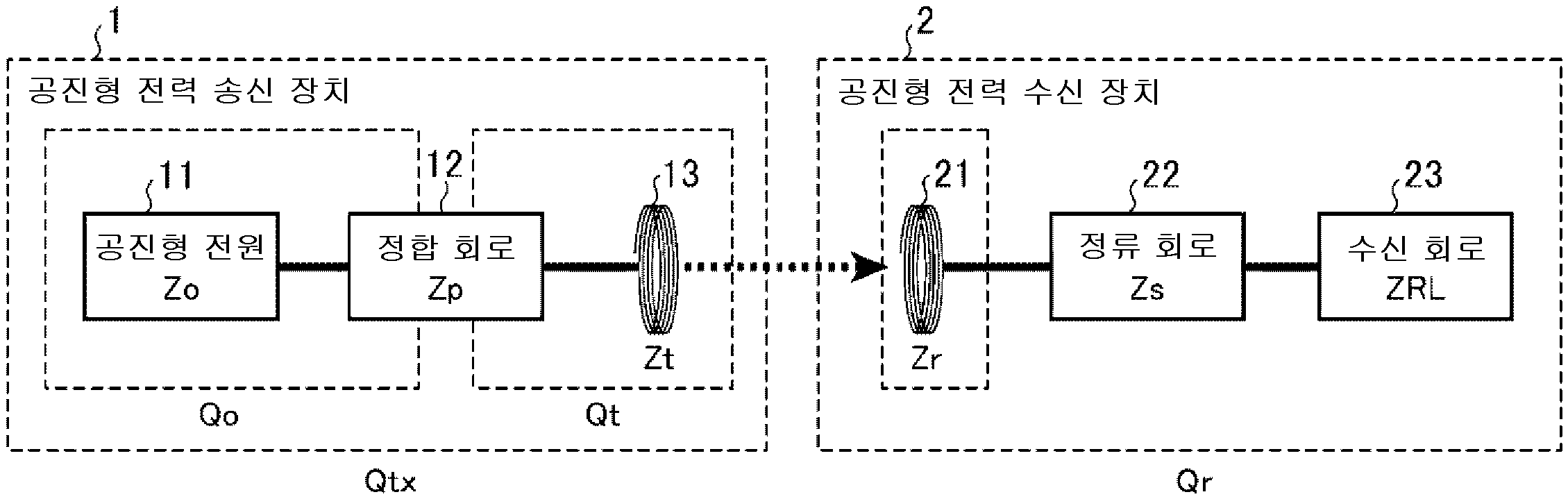
도 1은 본 발명의 실시의 형태 1에 따른 공진 결합형 전력 전송 시스템의 구성을 나타내는 도면이며, 도 2는 구체적인 회로도이다. 1 is a diagram showing a configuration of a resonance coupling power transmission system according to
공진 결합형 전력 전송 시스템은 도 1, 2에 나타내는 바와 같이, 공진형 전력 송신 장치(1) 및 공진형 전력 수신 장치(2)로 구성되어 있다. 또한 도 2에 나타내는 공진 결합형 전력 전송 시스템에서는, 후술하는 공진형 전원(11)의 공진 주파수가 2 MHz 이상인 경우를 나타내고 있지만, 2 MHz 미만의 것을 이용해도 좋다.The resonance coupling type power transmission system is composed of a resonance type
공진형 전력 송신 장치(1)는 공진형 전원(11), 정합 회로(12) 및 공진형 송신 안테나(13)로 구성되어 있다.The resonance type
공진형 전원(11)은 공진형 송신 안테나(13)로의 전력의 공급을 제어하는 것이며, 직류 또는 교류의 입력 전력을 소정의 주파수의 교류로 변환해서 출력하는 것이다. 이 공진형 전원(11)은 공진 스위칭 방식에 의한 전원 회로로 구성되고, 출력 임피던스 Zo, 공진 주파수 fo 및 공진 특성값 Qo를 갖는다.The resonance
정합 회로(12)는 공진형 전원(11)의 출력 임피던스 Zo와 공진형 송신 안테나(13)의 통과 특성 임피던스 Zt의 사이의 임피던스 정합을 행하는 것이다. 이 정합 회로(12)는 인덕터 L 및 캐패시터 C에 의한 π형이나 L형의 필터로 구성되고, 그 통과 특성 임피던스 Zp를 갖는다.The matching
공진형 송신 안테나(13)는 정합 회로(12)를 거친 공진형 전원(11)으로부터의 교류 전력이 입력되어 공진 동작을 행하고, 비방사형의 전자계를 근방에 발생시킴으로써, 공진형 수신 안테나(21)에 대해서 전력 전송을 행하는 것이다. 이 공진형 송신 안테나(13)는 코일 형상의 공진형 안테나이며, 그 통과 특성 임피던스 Zt, 공진 주파수 ft 및 공진 특성값 Qt를 갖는다.The resonance
또, 공진형 전원(11)의 공진 주파수 fo 및 공진 특성값 Qo는 공진형 전원(11)의 출력 임피던스 Zo와 정합 회로(12)의 통과 특성 임피던스 Zp로부터 정해진다. 공진형 송신 안테나(13)의 공진 주파수 ft 및 공진 특성값 Qt는 공진형 송신 안테나(13)의 통과 특성 임피던스 Zt와 정합 회로(12)의 통과 특성 임피던스 Zp로부터 정해진다.Further, the resonance frequency fo and the resonance characteristic value Qo of the resonance
그리고, 이 2개의 공진 특성값 Qo, Qt로부터, 공진형 전력 송신 장치(1)는 공진 특성값 Qtx=√(Qo·Qt)를 갖게 된다.Then, from these two resonance characteristic values Qo and Qt, the resonance type
공진형 전력 수신 장치(2)는 공진형 수신 안테나(21), 정류 회로(22) 및 수신 회로(23)에 의해 구성되어 있다. 이 공진형 전력 수신 장치(2)는 공진 주파수 fr 및 공진 특성값 Qr를 갖고 있다.The resonance type
공진형 수신 안테나(21)는 공진형 송신 안테나(13)로부터의 비방사형의 전자계와 공진 결합 동작을 행함으로써 전력을 수신하여, 교류 전력을 출력하는 것이다. 이 공진형 수신 안테나(21)는 코일 형상의 공진형 안테나이며, 그 통과 특성 임피던스 Zr를 갖는다.The resonance
정류 회로(22)는 공진형 수신 안테나(21)로부터의 교류 전력을 직류 전력으로 변환하는 정류 기능과, 공진형 수신 안테나(21)의 통과 특성 임피던스 Zr와 수신 회로(23)의 입력 임피던스 ZRL의 사이의 임피던스 정합을 행하는 정합 기능을 갖는 정합형 정류 회로이다. 정합 기능은 인덕터 L 및 캐패시터 C에 의한 π형이나 L형의 필터로 구성된다. 또, 정류 회로(22)는 통과 특성 임피던스 Zs를 갖는다. 또한 여기에서는, 정류 회로(22)가 정류 기능 및 정합 기능을 갖는 것으로 했지만, 이것에 한정하는 것이 아니고, 정류 효율은 떨어지지만 정류 기능만으로 구성해도 좋다.The
수신 회로(23)는 정류 회로(22)로부터의 직류 전력이 입력되어, 소정의 전압으로 변환해서 부하(미도시)에 공급하는 것이다. 이 수신 회로(23)는 고주파 전압 리플을 평활하기 위한 LC 필터(평활 필터)와, 소정의 전압으로 변환하기 위한 DC/DC 컨버터 등으로 구성되고, 그 입력 임피던스 ZRL를 갖고 있다. 또, DC/DC 컨버터를 마련하지 않고, 평활 필터만으로 구성해도 좋다.The receiving
또, 공진형 전력 수신 장치(2)의 공진 특성값 Qr 및 공진 주파수 fr는 공진형 수신 안테나(21)의 통과 특성 임피던스 Zr와, 정류 회로(22)의 통과 특성 임피던스 Zs와, 수신 회로(23)의 입력 임피던스 ZRL로부터 정해진다.In addition, the resonance characteristic value Qr and the resonance frequency fr of the resonance type
또, 공진형 송수신 안테나(13, 21)의 공진 결합에 의한 전력 전송 방식은 특별히 한정되는 것이 아니고, 자계 공명에 의한 방식, 전계 공명에 의한 방식, 전자기 유도에 의한 방식, 접촉형의 공진 결합 방식 중 어느 하나이어도 좋다.In addition, the power transmission method by resonance coupling of the resonant transmission/
그리고, 본 발명에서는, 공진형 전원(11)의 공진 특성값 Qo, 공진형 송신 안테나(13)의 공진 특성값 Qt 및 공진형 전력 수신 장치(2)의 공진 특성값 Qr이 상관 관계를 갖도록, 각 기능부의 특성 임피던스를 설정한다. 즉, 공진형 전력 송신 장치(1)의 공진 특성값 Qtx(=√(Qo·Qt))와 공진형 전력 수신 장치(2)의 공진 특성값 Qr이 근사하게 한다(아래의 식(2)). 구체적으로는 아래의 식(3)의 범위내이면 좋다.And, in the present invention, so that the resonance characteristic value Qo of the resonance
√(Qo·Qt)≒Qr (2) √(Qo·Qt)≒Qr (2)
0.5 Qr≤√(Qo·Qt)≤1.5 Qr (3)0.5 Qr≤√(QoQt)≤1.5 Qr (3)
이것에 의해, 공진형 송신 안테나(13)에 연결되는 공진형 전원(11)의 영향으로 인한 공진 특성값의 변동 및 공진형 수신 안테나(21)에 연결되는 수신 회로(23)의 영향으로 인한 공진 특성값의 변동을 고려해서, 공진형 전력 송신 장치(1) 및 공진형 전력 수신 장치(2)를 설정하는 것이 가능해진다. 그 결과, 시스템 전체적으로 고효율의 전력 전송이 가능해진다.Thereby, the variation of the resonance characteristic value due to the influence of the resonance
다음으로, 도 3을 이용해서, 공진형 송수신 안테나(13, 21) 간의 거리 d와 결합 계수 k(≒자속 쇄교율))의 관계에 대해 설명한다. 여기서, 공진형 송수신 안테나(13, 21)(나선형 안테나)의 지름 φ을 18 [㎝]로 했을 경우, 거리 d와 결합 계수 k의 관계는 도 3(b)과 같이 된다. 즉, 거리 d가 가까울수록 결합 계수 k가 커지고, 거리 d가 멀어질수록 결합 계수 k가 작아진다.Next, the relationship between the distance d between the resonant transmission/
그렇지만, 본 발명과 같이 3개의 공진 특성값 Qo, Qt, Qr이 상관 관계를 갖게 함으로써, 전력 전송 효율을 떨어뜨리지 않고, 공진형 송수신 안테나(13, 21) 간의 거리를 종래의 전자기 유도에 의한 거리보다 크게 할 수 있다.However, by making the three resonance characteristic values Qo, Qt, and Qr correlate as in the present invention, the distance between the resonance type transmission/
또, 공진형 전력 송신 장치(1)에 있어서, 아래의 식(4)을 만족하도록, 각 기능부의 특성 임피던스를 설정한다. 구체적으로는 아래의 식(5)의 범위내이면 좋다.In addition, in the resonance type
k√(Qo·Qt)≒1 (4) k√(Qo Qt)≒1 (4)
0.5≤k√(Qo·Qt)≤1.5 (5) 0.5≤k√(QoQt)≤1.5 (5)
또, 공진형 전력 수신 장치(2)에 있어서, 아래의 식(6)을 만족하도록, 각 기능부의 특성 임피던스를 설정한다. 구체적으로는 아래의 식(7)의 범위내이면 좋다.In addition, in the resonance type
k·Qr≒1 (6) k Qr≒1 (6)
0.5≤k·Qr≤1.5 (7) 0.5≤k·Qr≤1.5 (7)
이것에 의해, 도 4에 나타내는 바와 같이, 시스템 전체적으로의 전력 전송 효율을 보다 높일 수 있다.Thereby, as shown in FIG. 4, the power transmission efficiency of the whole system can be improved more.
또한, 도 5(a)에 나타내는 바와 같이, 식(2), (3)의 조건하에서, 공진형 송신 안테나(13)의 공진 주파수 ft(실선)와 공진형 수신 안테나(21)의 공진 주파수 fr(점선)를 상이한 값으로 설정한다. 이때, 이상적으로는, 공진 특성값 Qtx, Qr의 교점이 가장 높아지도록 공진 주파수 ft, fr를 어긋나게 하고, 또한, 해당 교점을 공진형 전원(11)의 공진 주파수 fo에 일치시킨다. 이것에 의해, 도 5(b)에 나타내는 바와 같이, 식(2), (3)에서의 공진 특성값을 최대에 근사하게 할 수 있어 공진 주파수(전송 주파수) fo에 있어서, 전력 전송 효율을 최대에 근사하게 할 수 있다.In addition, as shown in Fig. 5(a), under the conditions of equations (2) and (3), the resonance frequency ft (solid line) of the resonance
다음으로, 종래 장치와 본 발명의 차이에 대해 설명한다.Next, the difference between the conventional device and the present invention will be described.
종래 장치는, 상술한 바와 같이, 제 1 공진기 구조(공진형 송신 안테나)의 공진 특성값 Q1과 제 2 공진기 구조(공진형 수신 안테나)의 공진 특성값 Q2를, 식(1)을 만족하도록 높게 설정한 것이다. 한편, 본 발명에서는, 공진형 전원(11)의 공진 특성값 Qo, 공진형 송신 안테나(13)의 공진 특성값 Qt 및 공진형 전력 수신 장치(2)의 공진 특성값 Qr의 3개의 공진 특성값이 상관 관계를 갖게 한 것이다. 그 결과, 전력 전송 효율을 떨어뜨리지 않고, 공진형 송수신 안테나(13, 21) 간의 거리 d를 종래의 전자기 유도에 의한 거리보다 크게 할 수 있다. 즉, 본 발명에서는, 종래 장치의 공진 특성값 Q1, Q2에 상당하는 공진형 송수신 안테나(13, 21)의 공진 특성값 √(Qo·Qt), Qr가 종래 장치보다 낮은 경우에도, 원거리에 고효율의 전력 전송이 가능하다. 이하, 구체적인 예를 나타낸다.In the conventional apparatus, as described above, the resonance characteristic value Q1 of the first resonator structure (resonant transmission antenna) and the resonance characteristic value Q2 of the second resonator structure (resonant reception antenna) are increased to satisfy equation (1). I set it up. On the other hand, in the present invention, three resonance characteristic values of the resonance characteristic value Qo of the resonance
우선, 공진형 전원(11)의 공진 주파수 fo에 있어서, 공진형 전원(11)의 공진 특성값 Qo를 4로 설정하고, 공진형 송신 안테나(13)의 공진 특성값 Qt를 6으로 설정하고, 공진형 전력 수신 장치(2)의 공진 특성값 Qr를 5로 설정한 경우를 나타낸다.First, in the resonance frequency fo of the resonance
이 경우, 아래의 식(8)의 관계가 성립한다.In this case, the relationship of equation (8) below holds.
√(Qo·Qt)≒Qr≒5 (8)√(Qo Qt)≒Qr≒5 (8)
이때, 식(4), (6)로부터, 아래의 식(9)을 만족하는 결합 계수 k의 조건에서, 가장 고효율인 전력 전송이 가능해진다.At this time, from the equations (4) and (6), under the condition of the coupling coefficient k that satisfies the following equation (9), the most efficient power transmission becomes possible.
k≒1/5=0.2 (9)k≒1/5=0.2 (9)
여기서, 공진형 송수신 안테나(13, 21)의 지름 φ이 18[㎝]인 경우(도 3), 상기 결합 계수 k=0.2를 만족하기 위해서는, 공진형 송수신 안테나(13, 21)의 거리 d를 약 7 ㎝로 설정하면 좋다. 또, 그 공진형 송수신 안테나(13, 21) 간의 동손(銅損)을 제외한 전송 효율 η은 아래의 식(10)으로 된다.Here, when the diameter φ of the resonance type transmission/
η≒k√(√(Qo·Qt)·Qr)=99% (10)η≒k√(√(Qo·Qt)·Qr)=99% (10)
다음으로, 공진형 전원(11)의 공진 주파수 fo에 있어서, 공진형 전원(11)의 공진 특성값 Qo를 40으로 설정하고, 공진형 송신 안테나(13)의 공진 특성값 Qt를 60으로 설정하고, 공진형 전력 수신 장치(2)의 공진 특성값 Qr를 50으로 설정한 경우를 나타낸다.Next, in the resonance frequency fo of the resonance
이 경우, 아래의 식(11)의 관계가 성립한다.In this case, the relationship of equation (11) below holds.
√(Qo·Qt)≒Qr≒50 (11)√(Qo Qt)≒Qr≒50 (11)
이때, 식(4), (6)으로부터, 아래의 식(12)을 만족하는 결합 계수 k의 조건에서, 가장 고효율인 전력 전송이 가능해진다.At this time, from Equations (4) and (6), under the condition of the coupling coefficient k that satisfies Equation (12) below, the most efficient power transmission becomes possible.
k≒1/50=0.02 (12)k≒1/50=0.02 (12)
여기서, 공진형 송수신 안테나(13, 21)의 지름 φ이 18[cm]인 경우(도 3), 상기 결합 계수 k=0.02를 만족하기 위해서는, 공진형 송수신 안테나(13, 21)의 거리 d를 약 20 ㎝로 설정하면 좋다. 또, 그 공진형 송수신 안테나(13, 21) 간의 동손을 제외한 전송 효율 η은 식(10)으로 된다.Here, when the diameter φ of the resonance type transmission/
다음으로, 공진형 전원(11)의 공진 주파수 fo에 있어서, 공진형 전원(11)의 공진 특성값 Qo를 120으로 설정하고, 공진형 송신 안테나(13)의 공진 특성값 Qt를 80으로 설정하고, 공진형 전력 수신 장치(2)의 공진 특성값 Qr를 100으로 설정한 경우를 나타낸다.Next, in the resonance frequency fo of the resonance
이 경우, 아래의 식(13)의 관계가 성립한다.In this case, the relationship of equation (13) below holds.
√(Qo·Qt)≒Qr≒100 (13)√(Qo Qt)≒Qr≒100 (13)
이때, 식(4), (6)으로부터, 아래의 식(14)을 만족하는 결합 계수 k의 조건에서, 가장 고효율인 전력 전송이 가능해진다.At this time, from the equations (4) and (6), under the condition of the coupling coefficient k that satisfies the following equation (14), the most efficient power transmission becomes possible.
k≒1/100=0.01 (14)k≒1/100=0.01 (14)
여기서, 공진형 송수신 안테나(13, 21)의 지름 φ이 18[㎝]인 경우(도 3), 상기 결합 계수 k=0.01을 만족하기 위해서는, 공진형 송수신 안테나(13, 21)의 거리 d를 약 30 ㎝로 설정하면 좋다. 또, 그 공진형 송수신 안테나(13, 21) 간의 동손을 제외한 전송 효율 η은 식(10)으로 된다.Here, when the diameter φ of the resonance type transmission/
이상과 같이, 이 실시의 형태 1에 따르면, 공진형 전원(11)의 공진 특성값 Qo, 공진형 송신 안테나(13)의 공진 특성값 Qt 및 공진형 전력 수신 장치(2)의 공진 특성값 Qr이 상관 관계를 갖도록, 각 기능부의 특성 임피던스를 설정했으므로, 공진형 전원(11) 및 수신 회로(23)의 영향으로 인한 공진 특성값의 변동을 고려해서, 공진형 전력 송신 장치(1) 및 공진형 전력 수신 장치(2)를 설정하는 것이 가능해지고, 종래 장치에 대해서 시스템 전체적으로 전력 전송의 고효율화를 도모할 수 있다. 또, 공진형 송수신 안테나(13, 21)의 공진 특성값에 의존하지 않고, 전력 전송 효율을 떨어뜨리지 않고, 공진형 송수신 안테나(13, 21) 간의 거리를 종래의 전자기 유도에 의한 거리보다 멀게 할 수 있다.As described above, according to the first embodiment, the resonance characteristic value Qo of the resonance
또, 공진형 송수신 안테나(13, 21)의 공진 특성값을 높이지 않아도 좋기 때문에, 공진형 송수신 안테나(13, 21)는 공진 특성값으로 제한되지 않는 자유도가 있는 안테나 설계가 가능해지고, 소형화, 경량화, 저비용화가 가능해진다. 또, 공진형 송수신 안테나(13, 21)의 일부로서 이용되는 캐패시터에, 고내압의 캐패시터 등의 특수한 부품을 이용할 필요는 없기 때문에, 소형화, 경량화, 저비용화가 가능해진다.In addition, since it is not necessary to increase the resonance characteristic values of the resonance type transmission/
또, 본 발명의 공진형 전원(11)은 도 2에 나타내는 회로 구성에 한정하는 것이 아니고, 예를 들면 도 6에 나타내는 회로 구성으로 해도 좋다. 여기서, 도 6(a)은 브리지형 컨버터를 나타내고, 도 6(b)은 D급 컨버터를 나타내고, 도 6(c)은 DE급 컨버터를 나타내고 있다.In addition, the resonance
또, 본 발명의 정류 회로(22)는 도 2에 나타내는 회로 구성에 한정하는 것이 아니고, 예를 들면 도 7에 나타내는 회로 구성으로 해도 좋다. 여기서, 도 7(a)은 E급 정류 회로를 나타내고, 도 7(b)은 배전류 정류 회로를 나타내고, 도 7(c)은 반파 정류 회로를 나타내고, 도 7(d)은 배전압 정류 회로를 나타내고 있다.In addition, the rectifying
또 도 1에서는, 공진형 전력 송신 장치(1)에 정합 회로(12)를 마련한 경우를 나타냈다. 그렇지만, 이것에 한정하는 것이 아니고, 도 8에 나타내는 바와 같이, 정합 회로(12)를 마련하지 않고 구성해도 좋다. 이 경우, 공진형 전원(11)의 공진 주파수 fo 및 공진 특성값 Qo는 공진형 전원(11)의 출력 임피던스 Zo와 공진형 송신 안테나(13)의 통과 특성 임피던스 Zt로부터 정해진다. 또, 공진형 송신 안테나(13)의 공진 주파수 ft 및 공진 특성값 Qt는 공진형 송신 안테나(13)의 통과 특성 임피던스 Zt와 공진형 전원(11)의 출력 임피던스 Zo로부터 정해진다.In addition, in FIG. 1, the case where the matching
또, 본원 발명은 그 발명의 범위내에서, 실시의 형태의 임의의 구성 요소의 변형, 혹은 실시의 형태의 임의의 구성 요소의 생략이 가능하다.In the present invention, within the scope of the invention, it is possible to modify arbitrary constituent elements of the embodiment or omit arbitrary constituent elements of the embodiment.
(산업상의 이용 가능성)(Industrial availability)
본 발명에 따른 공진 결합형 전력 전송 시스템은 공진형 전원 및 수신 회로의 영향으로 인한 공진 특성값의 변동을 고려한 설정을 행하여, 종래 장치에 대해서 시스템 전체에서의 전력 전송의 고효율화를 도모할 수 있고, 공진형 송수신 안테나의 공진 특성을 이용해서 전력 전송을 행하는 공진 결합형 전력 전송 시스템 등에 이용하는데 적합하다.The resonant coupling type power transmission system according to the present invention is set in consideration of fluctuations in resonance characteristic values due to the influence of the resonance type power supply and the receiving circuit, thereby achieving high efficiency of power transmission throughout the system compared to a conventional device, It is suitable for use in a resonance coupling type power transmission system that transmits power by using the resonance characteristics of a resonance type transmit/receive antenna.
1 : 공진형 전력 송신 장치 2 : 공진형 전력 수신 장치
11 : 공진형 전원 12 : 정합 회로
13 : 공진형 송신 안테나 21 : 공진형 수신 안테나
22 : 정류 회로 23 : 수신 회로1: resonance type power transmission device 2: resonance type power reception device
11: resonance type power supply 12: matching circuit
13: resonance type transmitting antenna 21: resonance type receiving antenna
22: rectifier circuit 23: receiving circuit
Claims (10)
상기 공진형 송신 안테나에 의해 전송된 전력을 수신하는 공진형 수신 안테나 및 상기 공진형 수신 안테나에 의해 수신된 전력을 부하에 공급하는 수신 회로를 갖는 공진형 전력 수신 장치
를 구비하고,
상기 공진형 전원의 공진 특성값을 Qo로 하고, 상기 공진형 송신 안테나의 공진 특성값을 Qt로 하고, 상기 공진형 전력 수신 장치의 공진 특성값을 Qr로 했을 때, 0.5 Qr≤√(Qo·Qt)≤1.5 Qr를 만족하는
것을 특징으로 하는 공진 결합형 전력 전송 시스템.
A resonance type power transmission device having a resonance type power supply for supplying power and a resonance type transmission antenna for transmitting power supplied by the resonance type power source,
A resonance type power receiving device having a resonance type receiving antenna for receiving power transmitted by the resonance type transmitting antenna and a receiving circuit for supplying power received by the resonance type receiving antenna to a load
And,
When the resonance characteristic value of the resonance type power supply is set as Qo, the resonance characteristic value of the resonance type transmission antenna is set as Qt, and the resonance characteristic value of the resonance type power receiving device is Qr, 0.5 Qr≦√(Qo· Satisfying Qt)≤1.5 Qr
Resonant coupling type power transmission system, characterized in that.
상기 공진형 송신 안테나와 상기 공진형 수신 안테나의 사이의 결합 계수를 k로 했을 때, 0.5≤k√(Qo·Qt)≤1.5를 만족하는 것을 특징으로 하는 공진 결합형 전력 전송 시스템.
The method of claim 1,
When k is a coupling coefficient between the resonant transmission antenna and the resonant reception antenna, 0.5≦k√(Qo·Qt)≦1.5 is satisfied.
상기 공진형 송신 안테나와 상기 공진형 수신 안테나의 사이의 결합 계수를 k로 했을 때, 0.5≤k·Qr≤1.5를 만족하는 것을 특징으로 하는 공진 결합형 전력 전송 시스템.
The method of claim 1,
When k is a coupling coefficient between the resonance type transmission antenna and the resonance type reception antenna, 0.5≦k·Qr≦1.5 is satisfied.
상기 공진형 송신 안테나의 공진 주파수와 상기 공진형 수신 안테나의 공진 주파수는 상이한 것을 특징으로 하는 공진 결합형 전력 전송 시스템.
The method of claim 1,
Resonant coupling type power transmission system, characterized in that the resonant frequency of the resonant transmission antenna and the resonant frequency of the resonant reception antenna are different.
상기 공진형 전원의 공진 주파수는 2 MHz 이상인 것을 특징으로 하는 공진 결합형 전력 전송 시스템.
The method of claim 1,
Resonant coupled power transmission system, characterized in that the resonant frequency of the resonant power supply is 2 MHz or more.
상기 공진형 송신 안테나와 상기 공진형 수신 안테나의 사이의 공진 결합에 의한 전력 전송 방식은 자계, 전계, 전자기 유도 중 어느 하나인 것을 특징으로 하는 공진 결합형 전력 전송 시스템.
The method of claim 1,
Resonant coupling type power transmission system, characterized in that any one of a magnetic field, an electric field, and electromagnetic induction is used as a power transmission method by resonant coupling between the resonant transmission antenna and the resonant reception antenna.
상기 공진형 전원에 의해 공급된 전력을 전송하는 공진형 송신 안테나
를 갖고,
상기 공진형 전원의 공진 특성값을 Qo로 하고, 상기 공진형 송신 안테나의 공진 특성값을 Qt로 하고, 상기 공진형 송신 안테나에 의해 전송된 전력을 수신하는 공진형 수신 안테나 및 상기 공진형 수신 안테나에 의해 수신된 전력을 부하에 공급하는 수신 회로를 갖는 공진형 전력 수신 장치의 공진 특성값을 Qr로 했을 때, 0.5 Qr≤√(Qo·Qt)≤1.5 Qr를 만족하는
것을 특징으로 하는 공진형 전력 송신 장치.
A resonant power supply that supplies power,
Resonant transmission antenna for transmitting power supplied by the resonant power supply
Have,
A resonance type receiving antenna and the resonance type receiving antenna for receiving power transmitted by the resonance type transmitting antenna, with a resonance characteristic value of the resonance type power supply as Qo, a resonance characteristic value of the resonance type transmission antenna as Qt, and When the resonance characteristic value of a resonance type power receiving device having a receiving circuit that supplies the received power to the load is Qr, 0.5 Qr ≤ √(Qo Qt) ≤ 1.5 Qr is satisfied.
Resonant power transmission device, characterized in that.
전력을 공급하는 공진형 전원 및 상기 공진형 전원에 의해 공급된 전력을 전송하는 공진형 송신 안테나를 갖는 공진형 전력 송신 장치에 의해 전송된 전력을 수신하는 공진형 수신 안테나와,
상기 공진형 수신 안테나에 의해 수신된 전력을 부하에 공급하는 수신 회로
를 갖고,
상기 공진형 전원의 공진 특성값을 Qo로 하고, 상기 공진형 송신 안테나의 공진 특성값을 Qt로 하고, 상기 공진형 전력 수신 장치의 공진 특성값을 Qr로 했을 때, 0.5 Qr≤√(Qo·Qt)≤1.5 Qr를 만족하는
것을 특징으로 하는 공진형 전력 수신 장치.In the resonance type power receiving device,
A resonance type receiving antenna for receiving power transmitted by a resonance type power transmission device having a resonance type power supply supplying power and a resonance type transmission antenna transmitting power supplied by the resonance type power supply;
Receiving circuit for supplying the power received by the resonant receiving antenna to the load
Have,
When the resonance characteristic value of the resonance type power supply is set as Qo, the resonance characteristic value of the resonance type transmission antenna is set as Qt, and the resonance characteristic value of the resonance type power receiving device is Qr, 0.5 Qr≦√(Qo· Satisfying Qt)≤1.5 Qr
Resonant type power receiving device, characterized in that.
Applications Claiming Priority (1)
| Application Number | Priority Date | Filing Date | Title |
|---|---|---|---|
| PCT/JP2014/073067 WO2016035141A1 (en) | 2014-09-02 | 2014-09-02 | Resonance coupling power transmission system, resonance coupling power transmission device, and resonance coupling power reception device |
Publications (2)
| Publication Number | Publication Date |
|---|---|
| KR20170049510A KR20170049510A (en) | 2017-05-10 |
| KR102236047B1 true KR102236047B1 (en) | 2021-04-02 |
Family
ID=53534096
Family Applications (1)
| Application Number | Title | Priority Date | Filing Date |
|---|---|---|---|
| KR1020177006025A Active KR102236047B1 (en) | 2014-09-02 | 2014-09-02 | Resonance coupling power transmission system, resonance coupling power transmission device, and resonance coupling power reception device |
Country Status (7)
| Country | Link |
|---|---|
| US (1) | US10158254B2 (en) |
| EP (1) | EP3190684B1 (en) |
| JP (1) | JP5738497B1 (en) |
| KR (1) | KR102236047B1 (en) |
| CN (1) | CN106797143B (en) |
| TW (1) | TWI515994B (en) |
| WO (1) | WO2016035141A1 (en) |
Families Citing this family (14)
| Publication number | Priority date | Publication date | Assignee | Title |
|---|---|---|---|---|
| WO2017126112A1 (en) * | 2016-01-22 | 2017-07-27 | 三菱電機エンジニアリング株式会社 | Power transmission device, high-frequency power supply, and high-frequency rectification circuit |
| JP6676174B2 (en) * | 2016-08-26 | 2020-04-08 | マクセル株式会社 | Non-contact power receiving device, non-contact power transmitting device, and non-contact power transmitting and receiving device |
| US10727697B2 (en) * | 2016-09-14 | 2020-07-28 | Witricity Corporation | Power flow controller synchronization |
| WO2018138872A1 (en) | 2017-01-27 | 2018-08-02 | 三菱電機株式会社 | Induction heating cooker |
| EP3595130B1 (en) * | 2017-03-10 | 2022-01-12 | Mitsubishi Electric Engineering Company, Limited | Resonance-type power reception device |
| CN110383632B (en) * | 2017-03-10 | 2023-09-26 | 三菱电机工程技术株式会社 | Resonant power transmitting device and resonant power transmission system |
| JP6312936B1 (en) * | 2017-04-24 | 2018-04-18 | 三菱電機エンジニアリング株式会社 | Resonant power receiver |
| CN107508386A (en) * | 2017-07-31 | 2017-12-22 | 惠州硕贝德无线科技股份有限公司 | A kind of onboard wireless charging circuit of low interference |
| US11533790B2 (en) * | 2017-10-12 | 2022-12-20 | Mitsubishi Electric Corporation | Induction cooker |
| JP7061548B2 (en) * | 2018-10-04 | 2022-04-28 | 株式会社日立産機システム | Resonant power supply |
| JP7270212B2 (en) * | 2019-05-07 | 2023-05-10 | 株式会社デンソー | wireless power supply |
| JP7401251B2 (en) * | 2019-10-10 | 2023-12-19 | キヤノン株式会社 | Power transmission equipment and wireless power transmission systems |
| CN112803612A (en) * | 2021-01-14 | 2021-05-14 | 成都斯普奥汀科技有限公司 | Magnetic resonance coupling wireless charging device based on differential structure |
| US20220244278A1 (en) * | 2021-02-01 | 2022-08-04 | POSTECH Research and Business Development Foundation | NANO-PROBE FOR MEASURING pH IN SINGLE CELLS, AND METHOD AND APPARATUS FOR MEASURING pH IN SINGLE CELLS USING THE SAME |
Citations (1)
| Publication number | Priority date | Publication date | Assignee | Title |
|---|---|---|---|---|
| US20110074218A1 (en) | 2005-07-12 | 2011-03-31 | Aristedis Karalis | Wireless energy transfer |
Family Cites Families (10)
| Publication number | Priority date | Publication date | Assignee | Title |
|---|---|---|---|---|
| AU2006269374C1 (en) | 2005-07-12 | 2010-03-25 | Massachusetts Institute Of Technology | Wireless non-radiative energy transfer |
| CN101682216B (en) | 2007-03-27 | 2013-06-26 | 麻省理工学院 | wireless energy transfer |
| US9634730B2 (en) * | 2007-07-09 | 2017-04-25 | Qualcomm Incorporated | Wireless energy transfer using coupled antennas |
| CN101842962B (en) * | 2007-08-09 | 2014-10-08 | 高通股份有限公司 | Increasing the Q factor of a resonator |
| JP2010537496A (en) | 2007-08-13 | 2010-12-02 | クゥアルコム・インコーポレイテッド | Long range low frequency resonators and materials |
| US8970070B2 (en) * | 2010-07-02 | 2015-03-03 | Panasonic Intellectual Property Management Co., Ltd. | Wireless power transmission system |
| JP5645582B2 (en) * | 2010-10-07 | 2014-12-24 | 株式会社日立情報通信エンジニアリング | Resonant charging device and vehicle using the same |
| US9350193B2 (en) * | 2011-06-01 | 2016-05-24 | Samsung Electronics Co., Ltd. | Method and apparatus for detecting load fluctuation of wireless power transmission |
| WO2013035188A1 (en) * | 2011-09-08 | 2013-03-14 | 富士通株式会社 | Transmitting device, receiving device, and non-contact charging method |
| US9496731B2 (en) | 2012-01-20 | 2016-11-15 | Samsung Electronics Co., Ltd | Apparatus and method for transmitting wireless power by using resonant coupling and system for the same |
-
2014
- 2014-09-02 KR KR1020177006025A patent/KR102236047B1/en active Active
- 2014-09-02 JP JP2014555886A patent/JP5738497B1/en active Active
- 2014-09-02 EP EP14901211.4A patent/EP3190684B1/en active Active
- 2014-09-02 CN CN201480081667.7A patent/CN106797143B/en active Active
- 2014-09-02 WO PCT/JP2014/073067 patent/WO2016035141A1/en not_active Ceased
- 2014-09-02 US US15/320,215 patent/US10158254B2/en active Active
-
2015
- 2015-04-17 TW TW104112378A patent/TWI515994B/en active
Patent Citations (1)
| Publication number | Priority date | Publication date | Assignee | Title |
|---|---|---|---|---|
| US20110074218A1 (en) | 2005-07-12 | 2011-03-31 | Aristedis Karalis | Wireless energy transfer |
Also Published As
| Publication number | Publication date |
|---|---|
| EP3190684A4 (en) | 2018-05-02 |
| JPWO2016035141A1 (en) | 2017-04-27 |
| CN106797143A (en) | 2017-05-31 |
| EP3190684A1 (en) | 2017-07-12 |
| EP3190684B1 (en) | 2019-11-06 |
| KR20170049510A (en) | 2017-05-10 |
| US10158254B2 (en) | 2018-12-18 |
| US20170155283A1 (en) | 2017-06-01 |
| JP5738497B1 (en) | 2015-06-24 |
| CN106797143B (en) | 2019-06-25 |
| TW201539928A (en) | 2015-10-16 |
| TWI515994B (en) | 2016-01-01 |
| WO2016035141A1 (en) | 2016-03-10 |
Similar Documents
| Publication | Publication Date | Title |
|---|---|---|
| KR102236047B1 (en) | Resonance coupling power transmission system, resonance coupling power transmission device, and resonance coupling power reception device | |
| US9991748B2 (en) | Wireless power transmission system and power transmission device | |
| JP6308371B2 (en) | Wireless power transmission device | |
| US10511194B2 (en) | Wireless power transfer system | |
| JP2011142724A (en) | Noncontact power transmission device and near field antenna for same | |
| JP6058222B1 (en) | Power transmission device, high frequency power supply and high frequency rectifier circuit | |
| WO2016124576A1 (en) | Rectifier for wireless power transfer | |
| US20160308398A1 (en) | Rectifying circuit for high-frequency power supply | |
| US9742307B2 (en) | Rectifying circuit for high-frequency power supply | |
| CN110383631B (en) | Resonant Power Receiver | |
| US10491043B2 (en) | Resonant coil, wireless power transmitter using the same, wireless power receiver using the same | |
| US9979315B2 (en) | Rectifying circuit for high-frequency power supply | |
| US20160285321A1 (en) | Rectifying circuit for high-frequency power supply | |
| JP6113360B1 (en) | Power transmission device and high frequency power supply | |
| WO2020189351A1 (en) | Non-contact power feeding device | |
| JP5989285B1 (en) | Power transmission device, high frequency power supply and high frequency rectifier circuit | |
| TW201725829A (en) | Transmission system, transmission device, and transmission method | |
| CN110383632A (en) | Resonance type power transmission device and resonance type power transmission system | |
| KR101745043B1 (en) | A wireless power transmission apparatus and method thereof | |
| KR101883684B1 (en) | Apparatus and method for transmitting wireless power using resonant coupling therefor system | |
| US20170163169A1 (en) | Rectifying circuit for high-frequency power supply |
Legal Events
| Date | Code | Title | Description |
|---|---|---|---|
| PA0105 | International application |
Patent event date: 20170303 Patent event code: PA01051R01D Comment text: International Patent Application |
|
| PG1501 | Laying open of application | ||
| PA0201 | Request for examination |
Patent event code: PA02012R01D Patent event date: 20190712 Comment text: Request for Examination of Application |
|
| E902 | Notification of reason for refusal | ||
| PE0902 | Notice of grounds for rejection |
Comment text: Notification of reason for refusal Patent event date: 20200831 Patent event code: PE09021S01D |
|
| E701 | Decision to grant or registration of patent right | ||
| PE0701 | Decision of registration |
Patent event code: PE07011S01D Comment text: Decision to Grant Registration Patent event date: 20210104 |
|
| GRNT | Written decision to grant | ||
| PR0701 | Registration of establishment |
Comment text: Registration of Establishment Patent event date: 20210330 Patent event code: PR07011E01D |
|
| PR1002 | Payment of registration fee |
Payment date: 20210330 End annual number: 3 Start annual number: 1 |
|
| PG1601 | Publication of registration | ||
| PR1001 | Payment of annual fee |
Payment date: 20240201 Start annual number: 4 End annual number: 4 |
|
| PR1001 | Payment of annual fee |
Payment date: 20250204 Start annual number: 5 End annual number: 5 |