CN100437278C - Display - Google Patents
Display Download PDFInfo
- Publication number
- CN100437278C CN100437278C CNB2005100788114A CN200510078811A CN100437278C CN 100437278 C CN100437278 C CN 100437278C CN B2005100788114 A CNB2005100788114 A CN B2005100788114A CN 200510078811 A CN200510078811 A CN 200510078811A CN 100437278 C CN100437278 C CN 100437278C
- Authority
- CN
- China
- Prior art keywords
- display
- liquid crystal
- liquid
- view
- crystal layer
- Prior art date
- Legal status (The legal status is an assumption and is not a legal conclusion. Google has not performed a legal analysis and makes no representation as to the accuracy of the status listed.)
- Expired - Fee Related
Links
Images


Classifications
-
- G—PHYSICS
- G02—OPTICS
- G02F—OPTICAL DEVICES OR ARRANGEMENTS FOR THE CONTROL OF LIGHT BY MODIFICATION OF THE OPTICAL PROPERTIES OF THE MEDIA OF THE ELEMENTS INVOLVED THEREIN; NON-LINEAR OPTICS; FREQUENCY-CHANGING OF LIGHT; OPTICAL LOGIC ELEMENTS; OPTICAL ANALOGUE/DIGITAL CONVERTERS
- G02F1/00—Devices or arrangements for the control of the intensity, colour, phase, polarisation or direction of light arriving from an independent light source, e.g. switching, gating or modulating; Non-linear optics
- G02F1/01—Devices or arrangements for the control of the intensity, colour, phase, polarisation or direction of light arriving from an independent light source, e.g. switching, gating or modulating; Non-linear optics for the control of the intensity, phase, polarisation or colour
- G02F1/13—Devices or arrangements for the control of the intensity, colour, phase, polarisation or direction of light arriving from an independent light source, e.g. switching, gating or modulating; Non-linear optics for the control of the intensity, phase, polarisation or colour based on liquid crystals, e.g. single liquid crystal display cells
- G02F1/1323—Arrangements for providing a switchable viewing angle
-
- G—PHYSICS
- G02—OPTICS
- G02F—OPTICAL DEVICES OR ARRANGEMENTS FOR THE CONTROL OF LIGHT BY MODIFICATION OF THE OPTICAL PROPERTIES OF THE MEDIA OF THE ELEMENTS INVOLVED THEREIN; NON-LINEAR OPTICS; FREQUENCY-CHANGING OF LIGHT; OPTICAL LOGIC ELEMENTS; OPTICAL ANALOGUE/DIGITAL CONVERTERS
- G02F1/00—Devices or arrangements for the control of the intensity, colour, phase, polarisation or direction of light arriving from an independent light source, e.g. switching, gating or modulating; Non-linear optics
- G02F1/01—Devices or arrangements for the control of the intensity, colour, phase, polarisation or direction of light arriving from an independent light source, e.g. switching, gating or modulating; Non-linear optics for the control of the intensity, phase, polarisation or colour
- G02F1/13—Devices or arrangements for the control of the intensity, colour, phase, polarisation or direction of light arriving from an independent light source, e.g. switching, gating or modulating; Non-linear optics for the control of the intensity, phase, polarisation or colour based on liquid crystals, e.g. single liquid crystal display cells
- G02F1/133—Constructional arrangements; Operation of liquid crystal cells; Circuit arrangements
- G02F1/1333—Constructional arrangements; Manufacturing methods
- G02F1/1347—Arrangement of liquid crystal layers or cells in which the final condition of one light beam is achieved by the addition of the effects of two or more layers or cells
- G02F1/13471—Arrangement of liquid crystal layers or cells in which the final condition of one light beam is achieved by the addition of the effects of two or more layers or cells in which all the liquid crystal cells or layers remain transparent, e.g. FLC, ECB, DAP, HAN, TN, STN, SBE-LC cells
-
- G—PHYSICS
- G02—OPTICS
- G02F—OPTICAL DEVICES OR ARRANGEMENTS FOR THE CONTROL OF LIGHT BY MODIFICATION OF THE OPTICAL PROPERTIES OF THE MEDIA OF THE ELEMENTS INVOLVED THEREIN; NON-LINEAR OPTICS; FREQUENCY-CHANGING OF LIGHT; OPTICAL LOGIC ELEMENTS; OPTICAL ANALOGUE/DIGITAL CONVERTERS
- G02F1/00—Devices or arrangements for the control of the intensity, colour, phase, polarisation or direction of light arriving from an independent light source, e.g. switching, gating or modulating; Non-linear optics
- G02F1/01—Devices or arrangements for the control of the intensity, colour, phase, polarisation or direction of light arriving from an independent light source, e.g. switching, gating or modulating; Non-linear optics for the control of the intensity, phase, polarisation or colour
- G02F1/13—Devices or arrangements for the control of the intensity, colour, phase, polarisation or direction of light arriving from an independent light source, e.g. switching, gating or modulating; Non-linear optics for the control of the intensity, phase, polarisation or colour based on liquid crystals, e.g. single liquid crystal display cells
- G02F1/133—Constructional arrangements; Operation of liquid crystal cells; Circuit arrangements
- G02F1/1333—Constructional arrangements; Manufacturing methods
- G02F1/1335—Structural association of cells with optical devices, e.g. polarisers or reflectors
- G02F1/13363—Birefringent elements, e.g. for optical compensation
- G02F1/133634—Birefringent elements, e.g. for optical compensation the refractive index Nz perpendicular to the element surface being different from in-plane refractive indices Nx and Ny, e.g. biaxial or with normal optical axis
-
- G—PHYSICS
- G02—OPTICS
- G02F—OPTICAL DEVICES OR ARRANGEMENTS FOR THE CONTROL OF LIGHT BY MODIFICATION OF THE OPTICAL PROPERTIES OF THE MEDIA OF THE ELEMENTS INVOLVED THEREIN; NON-LINEAR OPTICS; FREQUENCY-CHANGING OF LIGHT; OPTICAL LOGIC ELEMENTS; OPTICAL ANALOGUE/DIGITAL CONVERTERS
- G02F1/00—Devices or arrangements for the control of the intensity, colour, phase, polarisation or direction of light arriving from an independent light source, e.g. switching, gating or modulating; Non-linear optics
- G02F1/01—Devices or arrangements for the control of the intensity, colour, phase, polarisation or direction of light arriving from an independent light source, e.g. switching, gating or modulating; Non-linear optics for the control of the intensity, phase, polarisation or colour
- G02F1/13—Devices or arrangements for the control of the intensity, colour, phase, polarisation or direction of light arriving from an independent light source, e.g. switching, gating or modulating; Non-linear optics for the control of the intensity, phase, polarisation or colour based on liquid crystals, e.g. single liquid crystal display cells
- G02F1/133—Constructional arrangements; Operation of liquid crystal cells; Circuit arrangements
- G02F1/1333—Constructional arrangements; Manufacturing methods
- G02F1/1337—Surface-induced orientation of the liquid crystal molecules, e.g. by alignment layers
- G02F1/133753—Surface-induced orientation of the liquid crystal molecules, e.g. by alignment layers with different alignment orientations or pretilt angles on a same surface, e.g. for grey scale or improved viewing angle
-
- G—PHYSICS
- G02—OPTICS
- G02F—OPTICAL DEVICES OR ARRANGEMENTS FOR THE CONTROL OF LIGHT BY MODIFICATION OF THE OPTICAL PROPERTIES OF THE MEDIA OF THE ELEMENTS INVOLVED THEREIN; NON-LINEAR OPTICS; FREQUENCY-CHANGING OF LIGHT; OPTICAL LOGIC ELEMENTS; OPTICAL ANALOGUE/DIGITAL CONVERTERS
- G02F1/00—Devices or arrangements for the control of the intensity, colour, phase, polarisation or direction of light arriving from an independent light source, e.g. switching, gating or modulating; Non-linear optics
- G02F1/01—Devices or arrangements for the control of the intensity, colour, phase, polarisation or direction of light arriving from an independent light source, e.g. switching, gating or modulating; Non-linear optics for the control of the intensity, phase, polarisation or colour
- G02F1/13—Devices or arrangements for the control of the intensity, colour, phase, polarisation or direction of light arriving from an independent light source, e.g. switching, gating or modulating; Non-linear optics for the control of the intensity, phase, polarisation or colour based on liquid crystals, e.g. single liquid crystal display cells
- G02F1/137—Devices or arrangements for the control of the intensity, colour, phase, polarisation or direction of light arriving from an independent light source, e.g. switching, gating or modulating; Non-linear optics for the control of the intensity, phase, polarisation or colour based on liquid crystals, e.g. single liquid crystal display cells characterised by the electro-optical or magneto-optical effect, e.g. field-induced phase transition, orientation effect, guest-host interaction or dynamic scattering
- G02F1/139—Devices or arrangements for the control of the intensity, colour, phase, polarisation or direction of light arriving from an independent light source, e.g. switching, gating or modulating; Non-linear optics for the control of the intensity, phase, polarisation or colour based on liquid crystals, e.g. single liquid crystal display cells characterised by the electro-optical or magneto-optical effect, e.g. field-induced phase transition, orientation effect, guest-host interaction or dynamic scattering based on orientation effects in which the liquid crystal remains transparent
- G02F1/1393—Devices or arrangements for the control of the intensity, colour, phase, polarisation or direction of light arriving from an independent light source, e.g. switching, gating or modulating; Non-linear optics for the control of the intensity, phase, polarisation or colour based on liquid crystals, e.g. single liquid crystal display cells characterised by the electro-optical or magneto-optical effect, e.g. field-induced phase transition, orientation effect, guest-host interaction or dynamic scattering based on orientation effects in which the liquid crystal remains transparent the birefringence of the liquid crystal being electrically controlled, e.g. ECB-, DAP-, HAN-, PI-LC cells
-
- G—PHYSICS
- G02—OPTICS
- G02F—OPTICAL DEVICES OR ARRANGEMENTS FOR THE CONTROL OF LIGHT BY MODIFICATION OF THE OPTICAL PROPERTIES OF THE MEDIA OF THE ELEMENTS INVOLVED THEREIN; NON-LINEAR OPTICS; FREQUENCY-CHANGING OF LIGHT; OPTICAL LOGIC ELEMENTS; OPTICAL ANALOGUE/DIGITAL CONVERTERS
- G02F2413/00—Indexing scheme related to G02F1/13363, i.e. to birefringent elements, e.g. for optical compensation, characterised by the number, position, orientation or value of the compensation plates
- G02F2413/02—Number of plates being 2
-
- G—PHYSICS
- G02—OPTICS
- G02F—OPTICAL DEVICES OR ARRANGEMENTS FOR THE CONTROL OF LIGHT BY MODIFICATION OF THE OPTICAL PROPERTIES OF THE MEDIA OF THE ELEMENTS INVOLVED THEREIN; NON-LINEAR OPTICS; FREQUENCY-CHANGING OF LIGHT; OPTICAL LOGIC ELEMENTS; OPTICAL ANALOGUE/DIGITAL CONVERTERS
- G02F2413/00—Indexing scheme related to G02F1/13363, i.e. to birefringent elements, e.g. for optical compensation, characterised by the number, position, orientation or value of the compensation plates
- G02F2413/07—All plates on one side of the LC cell
Landscapes
- Physics & Mathematics (AREA)
- Nonlinear Science (AREA)
- Chemical & Material Sciences (AREA)
- Crystallography & Structural Chemistry (AREA)
- General Physics & Mathematics (AREA)
- Optics & Photonics (AREA)
- Mathematical Physics (AREA)
- Liquid Crystal (AREA)
- Electroluminescent Light Sources (AREA)
- Devices For Indicating Variable Information By Combining Individual Elements (AREA)
Abstract
Description
技术领域 technical field
本发明涉及一种显示器。The invention relates to a display.
发明背景Background of the invention
电子显示装置,例如用于计算机的监视器和内置于电话和便携式信息装置的屏幕,通常被设计为具有尽可能宽的视角,以使它们可被从任何观察位置来阅读。然而,在某些情况下,仅从较窄视角范围可见的显示器是有用的。例如,某人可能希望在拥挤的火车上阅读一份私人文件。Electronic display devices, such as monitors for computers and screens built into telephones and portable information devices, are generally designed to have as wide a viewing angle as possible so that they can be read from any viewing position. In some cases, however, a display that is only visible from a narrow range of viewing angles is useful. For example, someone may wish to read a private document on a crowded train.
已知多种限制视角范围或位置的装置,从这些视角范围或位置可观察到显示器。A variety of devices are known which limit the range of viewing angles or positions from which a display can be viewed.
US6552850公开了一项用于在自动提款机上显示私人信息的技术。由机器显示器发出的光具有固定的偏振态,机器及其使用者被一个大屏幕的偏振片所包围,偏振片吸收该偏振态的光,而透射正交态的偏振光。路过者可看到使用者和机器,但看不到屏幕上显示的信息。US6552850 discloses a technique for displaying private information on an automatic teller machine. The light emitted by the machine's display has a fixed polarization state, and the machine and its user are surrounded by a large screen of polarizers that absorb light in that polarization state and transmit light in an orthogonal state. Passers-by can see the user and the machine, but not the information displayed on the screen.
另一项用于控制光方向的已知技术为“百叶窗式(louvred)”薄膜。该薄膜包含以类似于软百叶窗帘方式布置的交替的透明层和不透明层。象软百叶窗帘那样,当光沿着几乎平行于这些层的方向传播时,它允许光穿过,但吸收那些相对于这些层的平面以较大角度传播的光。这些层可垂直于该薄膜表面或与其呈其它角度。Another known technique for controlling the direction of light is "louvred" films. The film comprises alternating transparent and opaque layers arranged in a manner similar to a Venetian blind. Like a venetian blind, it allows light to pass through when it travels in a direction nearly parallel to the layers, but absorbs light that travels at a larger angle relative to the plane of the layers. The layers may be perpendicular to the surface of the film or at other angles thereto.
百叶窗式薄膜可通过堆叠许多片交替的透明的和不透明的材料,然后垂直于这些层对所得块切片来制造。该方法已有多年为人所知。例如,该方法被公开于US2053173,US2689387和US3031351。Louvered films can be fabricated by stacking many sheets of alternating transparent and opaque material and then slicing the resulting block perpendicular to the layers. This method has been known for many years. For example, this method is disclosed in US2053173, US2689387 and US3031351.
USRE27617公开了一种工艺,其中百叶窗式薄膜被从一圆柱形堆积层毛坯连续地切割出来。US4766023显示了所得薄膜的光学质量和机械强度如何通过涂敷可紫外线固化的单体,然后将薄膜曝光于紫外线辐射来提高。US4764410公开了一种类似的工艺,其中可紫外线固化的材料被用于将百叶窗式片粘接到一个覆盖薄膜。USRE 27617 discloses a process in which a louvered film is continuously cut from a cylindrical build-up blank. US4766023 shows how the optical quality and mechanical strength of the resulting film can be improved by coating a UV curable monomer and then exposing the film to UV radiation. US4764410 discloses a similar process in which UV curable material is used to bond louvered sheets to a cover film.
还存在着制作与该百叶窗式薄膜性能相似的薄膜的其它方法。例如,US05147716公开了一种光控薄膜,该薄膜包含许多沿与薄膜平面垂直的方向排列的伸长颗粒。那些与该方向呈较大角度的光线被强烈吸收。There are other methods of making films with properties similar to this louvered film. For example, US05147716 discloses a light control film comprising a plurality of elongated particles aligned in a direction perpendicular to the plane of the film. Those rays at larger angles to that direction are strongly absorbed.
光控薄膜的另一实例被公开于US05528319。嵌入薄膜透明体内的是平行于该薄膜平面的两个层或更多层,每层具有透明和不透明区域。不透明区域阻挡光沿特定方向透射薄膜,而允许光沿其它方向的透射。Another example of a light control film is disclosed in US05528319. Embedded within the transparency of the film are two or more layers parallel to the plane of the film, each layer having transparent and opaque regions. Opaque regions block light from being transmitted through the film in certain directions, while allowing light to be transmitted in other directions.
上述薄膜可被置于显示板之前,或置于透射性显示板与其背光装置之间,以限制显示器可被观察到的角度范围。换句话说,它们使显示器“隐私化”。然而,它们都不能很方便地切换以允许从一个较宽的角度范围来观察。Such films can be placed in front of the display panel, or between a transmissive display panel and its backlight, to limit the range of angles at which the display can be viewed. In other words, they "private" the display. However, none of them can be easily switched to allow viewing from a wider range of angles.
US2002/0158967示出光控薄膜如何被安装在显示器上,以使光控薄膜在显示器前面移动,提供隐私模式,或机械地收缩进显示器后面或旁边的支架内,提供公开模式。然而,该方法有以下缺点:它包含运动部件,该运动部件可能失效或损坏,并给显示器增加了体积。US2002/0158967 shows how a light control film can be mounted on a display so that the light control film can be moved in front of the display to provide a private mode, or mechanically retracted into a stand behind or next to the display to provide a public mode. However, this approach has the disadvantage that it involves moving parts that can fail or be damaged, and adds bulk to the display.
另一种用于在公开模式和隐私模式之间切换而无需运动部件的已知技术是将光控薄膜安装在显示板之后,并在光控薄膜和显示板之间放置一散射体,该散射体可被电学地接通和切断。当该散射体处于非活动状态时,光控薄膜限制视角范围,从而显示器处于隐私模式。当散射体被接通时,它使光在较宽角度范围内行穿过显示板而传播,从而显示器处于公开模式。也可以将光控薄膜安装在显示板之前,并将可切换的散射体置于光控薄膜之前,以获得同样效果。此类可切换的隐私装置被描述于US5831698,US6211930和US05877829中。它们共有的缺点是无论显示器处于公开或隐私模式,光控薄膜总是吸收很大一部分入射到其上的光。因而该显示器在光的利用上是低效的。由于在公开模式下,散射体通过较宽角度范围散布光,因此这些显示器在公开模式下要比在隐私模式下更昏暗,除非背光被开得更亮,以加以补偿。Another known technique for switching between public and private modes without moving parts is to mount a light control film behind the display panel and place a diffuser between the light control film and the display panel. The body can be switched on and off electrically. When the scatterer is inactive, the LCF limits the viewing angle and the display is in privacy mode. When the diffuser is switched on, it causes light to travel across the display panel over a wide range of angles, so that the display is in open mode. It is also possible to mount the LCF in front of the display panel and place the switchable diffuser in front of the LCF to achieve the same effect. Such switchable privacy devices are described in US5831698, US6211930 and US05877829. The disadvantage they all have in common is that the LCF always absorbs a significant portion of the light incident on it, regardless of whether the display is in public or private mode. The display is thus inefficient in light utilization. Since the diffuser spreads light over a wider range of angles in public mode, these displays will be dimmer in public mode than in private mode, unless the backlight is turned on brighter to compensate.
第三种用于提供可切换的公开/隐私显示器的已知方法被公开于US5825436中。该专利中的光控装置在结构上与前述百叶窗式薄膜相似。然而,百叶窗式薄膜中的每个不透明元件被一液晶单元所替代,该液晶单元可被电学地从不透明状态切换到透明状态。该光控装置被置于显示板之前或之后。当这些单元为不透明时,显示器处于隐私模式;当这些单元为透明时,显示器处于公开模式。A third known method for providing a switchable public/private display is disclosed in US5825436. The light control device in this patent is similar in structure to the aforementioned louvered film. However, each opaque element in the louvered film is replaced by a liquid crystal cell that can be electrically switched from an opaque state to a transparent state. The light control device is placed in front of or behind the display panel. When the cells are opaque, the display is in private mode; when the cells are transparent, the display is in public mode.
该方法的第一个缺点是制造具有合适形状的液晶单元的困难和代价。第二个缺点是在隐私模式下,光线可能以一定角度进入,使得先穿过透明材料,然后穿过液晶单元的一部分。这样的光线将不会被液晶单元完全吸收,从而可能会降低该装置的隐私性。A first disadvantage of this approach is the difficulty and expense of fabricating liquid crystal cells of suitable shape. The second disadvantage is that in privacy mode, light may enter at an angle such that it first passes through the transparent material and then through part of the liquid crystal cell. Such light will not be fully absorbed by the liquid crystal cells, potentially reducing the privacy of the device.
JP2003-233074和JP2003-28263公开了一种液晶显示器,其提供了从垂直视角看去的常规的图像显示。然而,对于偏离显示器法线相对较大的视角,显示出一个固定图像,该固定图像可被用于隐藏或“搅乱”正常图像,从而提供隐私工作模式。该固定图像通过使显示区域具有互不相同的排列方向而获得,尽管所有像素以同一模式工作。在这种液晶显示器中,使用了一个低于正常值的驱动电压。JP2003-233074 and JP2003-28263 disclose a liquid crystal display that provides conventional image display from a vertical viewing angle. However, for viewing angles that are relatively large from normal to the display, a fixed image is displayed that can be used to hide or "scramble" the normal image, thereby providing a privacy mode of operation. This fixed image is obtained by making the display areas have mutually different arrangement directions, although all pixels operate in the same mode. In this liquid crystal display, a drive voltage lower than normal is used.
尽管这样一种装置可用于提供隐私模式,但是它是不可切换的。特别地,若需要非隐私工作时,该相对较窄的视角范围不能被改变,其中在整个该视角范围内,可看到非固定图像。Although such a device can be used to provide a privacy mode, it is not switchable. In particular, the relatively narrow range of viewing angles throughout which non-stationary images can be seen cannot be changed if non-private work is required.
尽管US6445434主要涉及一种在JP2003-233074和JP2003-28263中公开的单显示板、不可切换的隐私显示器类型,但是它确实公开了一种可在公开模式和隐私模式之间切换的双显示板显示器。用于显示图像的常规液晶显示器被设置在液晶装置之后,该液晶装置具有一个图案化的排列层,并可切换,以提供公开模式和隐私模式。在公开模式下,该装置对由显示器提供的视角几乎没有影响。在隐私模式下,使该排列层的图案在以偏离显示器法线的视角观察时为可见的,以提供一个“混淆”或“模糊”图案,意在使显示出的图像从这些视角观察时无法读懂。Although US6445434 is primarily concerned with a single-panel, non-switchable privacy display of the type disclosed in JP2003-233074 and JP2003-28263, it does disclose a dual-panel display switchable between public and private modes . A conventional liquid crystal display for displaying images is placed behind a liquid crystal device that has a patterned alignment layer and is switchable to provide public and private modes. In public mode, the device has little effect on the viewing angle provided by the display. In privacy mode, the pattern of the alignment layers is made visible when viewed from viewing angles that are off-normal to the display, to provide a "confused" or "blurred" pattern, intended to make the displayed image invisible when viewed from these viewing angles understand.
发明内容 Contents of the invention
根据本发明的第一方面,提供一种显示器,该显示器包含一个可控制的用以提供图像显示的显示装置,和一个具有至少一个液晶层的第一液晶装置,该液晶层的分子可在提供第一视角范围的第一状态和提供第二视角范围的第二状态之间切换,第二视角范围在第一视角范围之内并小于第一视角范围,第一液晶装置被布置成当液晶分子处于第二状态时,至少部分地阻挡朝向第一视角范围之一部分并在第二视角范围之外传播的光,该液晶层或每个液晶层与至少一个排列表面相接触,其特征在于:该液晶层或每个液晶层的该排列表面或每个排列表面包含一个均匀的非图案化的排列表面。According to a first aspect of the present invention, there is provided a display comprising a controllable display device for providing image display, and a first liquid crystal device having at least one liquid crystal layer whose molecules can be Switching between a first state of a first viewing angle range and a second state providing a second viewing angle range within and smaller than the first viewing angle range, the first liquid crystal device is arranged to act as liquid crystal molecules In a second state at least partially blocking light towards a portion of the first viewing range and propagating outside the second viewing range, the or each liquid crystal layer being in contact with at least one alignment surface, characterized in that: the The or each aligned surface of the or each liquid crystal layer comprises a uniform non-patterned aligned surface.
第一液晶装置可包含至少一个线偏振器。该液晶层或每个液晶层可包含向列液晶。该液晶层或每个液晶层可被布置成以未扭转向列、扭转向列、超扭转向列、垂直排列向列、扭转垂直排列向列和复合排列向列模式之一来工作。The first liquid crystal device may comprise at least one linear polarizer. The or each liquid crystal layer may comprise nematic liquid crystals. The or each liquid crystal layer may be arranged to operate in one of untwisted nematic, twisted nematic, super twisted nematic, homeotropic, twisted homeotropic and compound aligned nematic modes.
该液晶层或每个液晶层可为双稳态的。该液晶层或每个液晶层可为双稳态扭转向列或天顶双稳态向列(zenithal bistable nematic)层。The or each liquid crystal layer may be bistable. The or each liquid crystal layer may be a bistable twisted nematic or zenithal bistable nematic layer.
第一液晶装置可包含多个被布置成以相同模式工作的液晶层。该显示器可包含设置于第一和第二线偏振器之间的、具有相反扭转方向的第一和第二扭转向列液晶层。该显示器可包含设置于第二和第三线偏振器之间的、具有相反扭转方向的第三和第四扭转向列液晶层。The first liquid crystal device may comprise a plurality of liquid crystal layers arranged to operate in the same mode. The display may comprise first and second twisted nematic liquid crystal layers having opposite twist directions disposed between first and second linear polarizers. The display may comprise third and fourth twisted nematic liquid crystal layers having opposite twist directions disposed between the second and third linear polarizers.
该显示器可包含第一、第二和第三线偏振器,以及第一和第二垂直排列向列液晶层,第一层被布置在第一和第二偏振器之间,第二偏振器具有一个垂直于第一和第三偏振器之偏振方向的偏振方向,第一和第二状态分别为一个针轮状态和一个基本均匀的无扭转状态。The display may comprise first, second and third linear polarizers, and first and second homeotropic nematic liquid crystal layers, the first layer being disposed between the first and second polarizers, the second polarizer having a The polarization directions perpendicular to the polarization directions of the first and third polarizers, the first and second states are respectively a pinwheel state and a substantially uniform untwisted state.
该至少一个液晶层可包含一个布置在第一和第二偏振器之间、并具有一个液晶导向器方向的垂直排列向列液晶层,当切换时,其方位角基本上平行或垂直于第一和第二偏振器的透射轴。The at least one liquid crystal layer may comprise a homeotropically aligned nematic liquid crystal layer disposed between first and second polarizers and having a liquid crystal director orientation that, when switched, has an azimuth substantially parallel or perpendicular to the first and the transmission axis of the second polarizer.
该至少一个液晶层可包含一个布置在第一和第二偏振器之间、并具有一个排列方向的无扭转向列层,其方位角基本上平行于第一和第二偏振器的透射轴。The at least one liquid crystal layer may comprise a non-twisted nematic layer disposed between the first and second polarizers and having an alignment direction substantially parallel to the transmission axes of the first and second polarizers.
该第一液晶装置可包含一个固定的C板延迟器,该至少一个液晶层可包含一个可切换的C板延迟器,该可切换的C板延迟器可在第一状态和一个与之不同的第二状态之间切换,在第一状态下该固定延迟器的光学效果基本失效。该可切换的C板延迟器可在第二状态下基本无光学效果。该固定延迟器可为一个正C板延迟器。该至少一个液晶层可为一个胆甾型液晶层。The first liquid crystal device may comprise a fixed C-plate retarder, and the at least one liquid crystal layer may comprise a switchable C-plate retarder, the switchable C-plate retarder being in a first state and a different Switching between a second state in which the optical effect of the fixed retarder is substantially disabled. The switchable C-plate retarder can be substantially optically ineffective in the second state. The fixed retarder may be a positive C-plate retarder. The at least one liquid crystal layer may be a cholesteric liquid crystal layer.
该第一液晶装置可被布置为,当液晶分子处于第二状态时,基本上阻挡所有朝向第一视角范围部分传播的光。The first liquid crystal device may be arranged to block substantially all light propagating towards part of the first viewing angle range when the liquid crystal molecules are in the second state.
第一液晶装置可包含至少一个电极,该电极或每个电极为均匀的,且未被图案化。The first liquid crystal device may comprise at least one electrode, the or each electrode being uniform and not patterned.
该第一液晶装置可被布置为,当液晶分子处于第二状态时,在朝向第一视角范围部分传播的光上,叠加一个沿空间变化的振幅,构成一个模糊图案,用于使由显示装置显示出的图像成为基本上不可被读懂。第一液晶装置可包含至少一个用第一图案进行图案化的电极,该至少一个电极可被图案化,以确定该至少一个液晶层的第一和第二区域,用于在分子处于第二状态时,对传播进入第一视角范围部分的光,分别提供第一和第二次衰减。该第一和第二次衰减可分别为最小和最大衰减。该第二区域可为非活动的,并可通过一个最小绝缘间隙与该第一区域分隔开来。The first liquid crystal device may be arranged such that, when the liquid crystal molecules are in the second state, a spatially varying amplitude is superimposed on the light propagating toward the portion of the first viewing angle range to form a blur pattern for use by the display device. Displayed images become largely unreadable. The first liquid crystal device may comprise at least one electrode patterned with a first pattern, the at least one electrode may be patterned to define first and second regions of the at least one liquid crystal layer for use when the molecules are in the second state When , the first and second attenuation are respectively provided for the light propagating into the part of the first viewing angle range. The first and second attenuations may be minimum and maximum attenuations, respectively. The second region may be inactive and may be separated from the first region by a minimum insulating gap.
该第一图案可为一个代表文本的图案。The first pattern can be a pattern representing text.
该第一图案可为一个棋盘格图案.The first pattern may be a checkerboard pattern.
该第一图案可为构成一个光学假象的一个图案。The first pattern may be a pattern constituting an optical artifact.
该第一液晶装置可再包含一个电极,该电极用不同于第一图案的第二图案进行图案化。第一和第二图案可具有不同的特征尺寸。The first liquid crystal device may further include an electrode patterned with a second pattern different from the first pattern. The first and second patterns may have different feature sizes.
该至少一个图案化的电极可包含一个可寻址的矩阵,以允许模糊图案的选择。显示器可包含一个电极驱动装置,以产生一个随时间变化的模糊图案。The at least one patterned electrode may comprise an addressable matrix to allow selection of blur patterns. The display may contain an electrode driver to produce a time-varying blur pattern.
该电极可被布置成向该至少一个液晶层施加一个电压,该电压从该至少一个液晶层的中心至边缘而变化,从而补偿边缘的偏离垂直观察的效应。The electrode may be arranged to apply a voltage to the at least one liquid crystal layer, the voltage varying from the center to the edge of the at least one liquid crystal layer, thereby compensating for off-perpendicular viewing effects of the edge.
当分子处于第二状态时,该第一和第二区域对于在第二视角范围内的角度,可具有基本相同的“透射率(transmission)~与显示器法线之角度”的关系函数,而对于在第一视角范围之内、且在第二视角范围之外的角度,则具有不同的函数。当分子处于第二状态时,确定第一和第二区域的电极可被布置成接收不同的电压。显示器可包含一个与该至少一个液晶层协作的补偿层,以提供相同的功能。该补偿层可被布置成,当分子处于第一状态时,基本上被禁用。该补偿层可包含液晶。When the molecule is in the second state, the first and second regions may have substantially the same relationship function of "transmission (transmission) ∼ angle to display normal" for angles within the second viewing range, and for Angles within the range of the first viewing angle and outside the range of the second viewing angle have different functions. The electrodes defining the first and second regions may be arranged to receive different voltages when the molecule is in the second state. The display may comprise a compensation layer cooperating with the at least one liquid crystal layer to provide the same function. The compensation layer may be arranged to be substantially disabled when the molecules are in the first state. The compensation layer may contain liquid crystals.
该至少一个液晶层可包含一个表面模式层,该补偿层可包含一个该表面模式层的表面区域。The at least one liquid crystal layer may comprise a surface mode layer, and the compensation layer may comprise a surface region of the surface mode layer.
根据本发明的第二方面,提供一种显示器,该显示器包含一个可控制的用以提供图像显示的液晶装置,和一个具有至少一个液晶层的第一液晶装置,该液晶层的分子可在提供第一视角范围的第一状态和提供第二视角范围的第二状态之间切换,第二视角范围在第一视角范围之内并小于第一视角范围,第一液晶装置被布置成当液晶分子处于第二状态时,至少部分地阻挡朝向第一视角范围之一部分并在第二视角范围之外传播的光,该至少一个液晶层与至少一个图案化的、含有第一和第二区域的排列表面相接触,该第一和第二区域具有不同的排列方向,其特征在于:该至少一个液晶层包含电子控制双折射单元和垂直排列向列液晶层中的一个。According to a second aspect of the present invention, there is provided a display comprising a controllable liquid crystal device for providing image display, and a first liquid crystal device having at least one liquid crystal layer whose molecules can be Switching between a first state of a first viewing angle range and a second state providing a second viewing angle range within and smaller than the first viewing angle range, the first liquid crystal device is arranged to act as liquid crystal molecules When in the second state, at least partially blocking light towards a portion of the first viewing range and propagating outside the second viewing range, the at least one liquid crystal layer is associated with at least one patterned array comprising first and second regions The surfaces are in contact, the first and second regions have different alignment directions, and it is characterized in that the at least one liquid crystal layer comprises one of an electronically controlled birefringence unit and a homeotropically aligned nematic liquid crystal layer.
该排列方向可基本上相互垂直,第一视角范围的一部分围绕显示器法线沿方位角方向可基本上等角地间隔开来。The alignment directions may be substantially perpendicular to each other, and portions of the first viewing angle range may be substantially equiangularly spaced in azimuthal direction around a normal to the display.
第一液晶装置可从显示装置上拆除,并可附加到显示装置上,以允许显示器在无第一液晶装置情况下的操作。The first liquid crystal device is detachable from the display device and attachable to the display device to allow operation of the display without the first liquid crystal device.
第二视角范围可包含显示器法线。The second viewing angle range may include the display normal.
第二视角范围可具有一个不垂直于显示器的平分线。The second range of viewing angles may have a bisector that is not perpendicular to the display.
第二视角范围可包含相对于显示器以不同的天顶角布置的第一和第二子范围。The second range of viewing angles may comprise first and second sub-ranges arranged at different zenith angles relative to the display.
第二视角范围可基本上为旋转对称的。The second range of viewing angles may be substantially rotationally symmetric.
显示器可被布置成,当分子处于第二状态时,显示一个标志。显示器可被布置成,响应于欲显示的数据内容而显示该标志。The display may be arranged to display a flag when the molecule is in the second state. The display may be arranged to display the indicia in response to the content of the data to be displayed.
显示装置可为透射性的。第一液晶装置可被布置在显示装置和背光之间。The display device may be transmissive. The first liquid crystal device may be arranged between the display device and the backlight.
显示装置可为反射性的。The display device may be reflective.
显示装置可为半透反射的(transflective)。The display device may be transflective.
显示装置可包含一个第二液晶装置。The display device may include a second liquid crystal device.
显示装置可为发光的。显示装置可为一个有机发光装置。显示器可在显示装置和液晶装置之间包含一个圆偏振器。显示装置可被布置成发出线偏振光。The display device may be illuminated. The display device can be an organic light emitting device. The display may contain a circular polarizer between the display device and the liquid crystal device. The display device may be arranged to emit linearly polarized light.
第一液晶装置可布置在显示装置之前。The first liquid crystal device may be arranged before the display device.
显示器可包含一个环境光传感器,用于在环境光低于某一阈值时,使显示器提供第二视角范围。The display may include an ambient light sensor for enabling the display to provide a second range of viewing angles when the ambient light is below a certain threshold.
显示器可包含一个车辆显示器。The displays may include a vehicle display.
这样便可能提供一种显示器,其视角可在例如一个宽视野模式和一个窄(或隐私)视野模式之间切换。第一液晶装置可与一个显示装置配合使用,该显示装置可为任何合适类型,且其操作无需为了提供宽和窄视野模式而变化。This makes it possible to provide a display whose viewing angle can be switched, for example, between a wide field of view mode and a narrow (or private) field of view mode. The first liquid crystal device may be used in conjunction with a display device, which may be of any suitable type and whose operation need not be altered to provide wide and narrow viewing modes.
这样的一个显示器可被用于,例如,台式计算机监视器、移动电话、个人数字助理(PDA)、移动电视、移动DVD(数字通用光盘,)播放器/录制机、电子销售点(EPOS)终端和现金ATM(自动取款机)。这样一种装置简单易行,且可通过众所周知的和既定的制造技术来制造。在某些实施例中,第一液晶装置不需要任何电极图案化或内部结构,例如,来确定象素。如果第一液晶装置具有单一的液晶区域,用于横跨整个显示装置而切换视角范围,则可使用一个非常简单的电极图案,且是易于制造的。尽管显示器可在第一和第二视角范围之间切换,但是视角可通过例如向第一液晶装置施加合适的驱动电压,连续或逐步地变化。Such a display can be used, for example, in desktop computer monitors, mobile phones, personal digital assistants (PDAs), mobile televisions, mobile DVD (Digital Versatile Disc,) players/recorders, electronic point-of-sale (EPOS) terminals and cash ATM (automated teller machine). Such a device is simple and can be manufactured by well known and established manufacturing techniques. In some embodiments, the first liquid crystal device does not require any electrode patterning or internal structures, eg, to define pixels. If the first liquid crystal device has a single liquid crystal region for switching the viewing angle range across the entire display device, a very simple electrode pattern can be used and is easy to manufacture. Although the display is switchable between the first and second viewing angle ranges, the viewing angle can be changed continuously or stepwise, eg by applying a suitable drive voltage to the first liquid crystal device.
这种显示器可用于需要一个具有宽视角的、通用的“公开”模式,以及一个具有窄视角的“隐私”模式的应用中,以便例如,可在公共场合阅读隐私信息。Such a display can be used in applications that require a general-purpose "public" mode with a wide viewing angle, and a "private" mode with a narrow viewing angle, so that, for example, private information can be read in public.
这样的显示器的另一应用是在车辆仪表板中。例如,显示器视角可被控制,以使乘客或司机不能看到显示。或者,可控制视角,以减少显示器在挡风玻璃和车窗上的反射,特别是在夜间或光线较暗情况下。为提供自动控制,例如,可配备一个亮度传感器和一个背光亮度控制器。Another application of such displays is in vehicle dashboards. For example, the display viewing angle can be controlled so that the passenger or driver cannot see the display. Alternatively, the viewing angle can be controlled to reduce reflections of the display on windshields and windows, especially at night or in low light. To provide automatic control, for example, a brightness sensor and a backlight brightness controller can be provided.
在另外一个应用中,第一液晶装置充当一个可切换的补偿薄膜。液晶显示器通常用静态补偿薄膜层叠起来,以提高视角特性。这种已知的结构通常被布置成在某一方向上可给出最好的效果,通常为水平方向。对于一个可旋转、且可以横向或纵向模式来观察的显示器,能够切换补偿薄膜,以便根据显示内容给出改良的效果,这将是有利的。In another application, the first liquid crystal device acts as a switchable compensation film. Liquid crystal displays are usually laminated with static compensation films to improve viewing angle characteristics. Such known structures are usually arranged to give the best results in a certain direction, usually horizontal. For a display that is rotatable and can be viewed in landscape or portrait mode, it would be advantageous to be able to switch the compensation film to give improved results depending on the displayed content.
这样的显示器也可用在两个或多个图像被在空间上复合、并被显示装置显示的应用场合中。例如,这样的显示器可具有第一模式,其中一个图像横跨显示器而被显示,以及第二模式,其中两个或多个不同的图像横跨显示器以空间复合的方式而被显示。不同的模式可能需要不同的光学补偿,可利用一个可切换的补偿器来达到此目的。Such displays can also be used in applications where two or more images are spatially composited and displayed by a display device. For example, such a display may have a first mode in which one image is displayed across the display, and a second mode in which two or more different images are displayed in a spatially compounded manner across the display. Different modes may require different optical compensations, which can be achieved with a switchable compensator.
附图简述Brief description of the drawings
图1a和1b为示意性地说明构成本发明实施例的显示器的图解;Figures 1a and 1b are diagrams schematically illustrating a display constituting an embodiment of the present invention;
图2a和2b为显示器的横剖面示意图,该显示器构成本发明实施例,与常规显示器相比,具有单一的附加液晶层;Figures 2a and 2b are schematic cross-sectional views of a display constituting an embodiment of the invention having a single additional liquid crystal layer compared to a conventional display;
图3a和3b为显示器的横剖面示意图,该显示器构成本发明实施例,与常规显示器相比,具有两个附加液晶层;Figures 3a and 3b are schematic cross-sectional views of a display constituting an embodiment of the invention having two additional liquid crystal layers compared to a conventional display;
图3c示出一个横剖面示意图,以及一个阐明图3a显示器之一实例的方位角定位的视图;Figure 3c shows a schematic cross-sectional view, and a view illustrating the azimuthal orientation of one example of the display of Figure 3a;
图4a和4b为阐明图3c所示显示器的宽和窄工作模式的光强度图;Figures 4a and 4b are light intensity graphs illustrating the wide and narrow modes of operation of the display shown in Figure 3c;
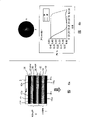
图5a为构成本发明一个实施例的显示器的横剖面示意图,与常规显示器相比,具有四个附加液晶层;Figure 5a is a schematic cross-sectional view of a display constituting one embodiment of the present invention, compared to a conventional display, having four additional liquid crystal layers;
图5b示出了图5a显示器的工作的光强度图;Figure 5b shows a light intensity diagram for the operation of the display of Figure 5a;
图6a为构成本发明的一个实施例的显示器的横剖面示意图,与常规显示器相比,具有两个附加液晶层;Figure 6a is a schematic cross-sectional view of a display constituting an embodiment of the present invention, compared to a conventional display, having two additional liquid crystal layers;
图6b示出图6a显示器的光强度图;Figure 6b shows a light intensity map for the display of Figure 6a;
图7a和7b针对图6a所示附加液晶层的宽和窄视野模式,阐明了液晶布置;Figures 7a and 7b illustrate the liquid crystal arrangement for wide and narrow field of view modes with the additional liquid crystal layer shown in Figure 6a;
图8为构成本发明的一个实施例的显示器的横剖面示意图,与常规显示器相比,具有单一的附加液晶层和一个静态补偿薄膜层;Figure 8 is a schematic cross-sectional view of a display constituting an embodiment of the present invention, as compared to a conventional display, having a single additional liquid crystal layer and a static compensation film layer;
图9a至9c示意性地阐明了显示器的使用,该显示器具有一个双观察模式,用于向不同的观察者提供两个独立的景象,以及一个单观察宽角模式;Figures 9a to 9c illustrate schematically the use of a display having a dual view mode for providing two independent views to different observers, and a single view wide angle mode;
图10a和10b为构成本发明一个实施例的一个显示器的、类似于图3c的示意图;Figures 10a and 10b are schematic diagrams similar to Figure 3c of a display constituting an embodiment of the present invention;
图11a和11b为阐明图10a和10b显示器的宽和窄工作模式的光强度图;Figures 11a and 11b are light intensity graphs illustrating the wide and narrow modes of operation of the displays of Figures 10a and 10b;
图12a和12b为构成本发明另一个实施例的一个显示器的、类似于图3c的示意图;Figures 12a and 12b are schematic views similar to Figure 3c of a display constituting another embodiment of the present invention;
图13a和13b为阐明图12a和12b显示器的宽和窄工作模式的光强度图;Figures 13a and 13b are light intensity graphs illustrating the wide and narrow modes of operation of the displays of Figures 12a and 12b;
图14至16阐明了电极图案化的实例;Figures 14 to 16 illustrate examples of electrode patterning;
图17针对一个显示器,阐明了一个电极布置和驱动方案;Figure 17 illustrates an electrode arrangement and driving scheme for a display;
图18阐明了显示器边缘的偏离法线观察的效果;Figure 18 illustrates the effect of off-normal viewing of the edges of the display;
图19a阐明了一个已图案化排列的液晶层的图案化;Figure 19a illustrates the patterning of a patterned aligned liquid crystal layer;
图19b示出了针对具有图19a所示排列的不同区域的光强度图;Figure 19b shows a graph of light intensity for different regions having the arrangement shown in Figure 19a;
图20为构成本发明一个实施例的显示器的横剖面示意图;FIG. 20 is a schematic cross-sectional view of a display constituting an embodiment of the present invention;
图21a和21b为阐明显示器理想和实际透射特性的透射率与角度关系的视图;Figures 21a and 21b are graphs of transmittance versus angle illustrating ideal and actual transmittance characteristics of a display;
图22阐明了另一个电极布置和驱动方案;Figure 22 illustrates another electrode arrangement and drive scheme;
图23至28为阐明构成本发明更多实施例的显示器的横剖面示意图;23 to 28 are schematic cross-sectional views illustrating displays constituting further embodiments of the present invention;
图29示意性地示出了图28所示显示器的视角特性;Figure 29 schematically shows the viewing angle characteristics of the display shown in Figure 28;
图30a和30b为阐明构成本发明另一个实施例的显示器的图解;并且,30a and 30b are diagrams illustrating a display constituting another embodiment of the present invention; and,
图31a和31b为阐明图30a和30b显示器工作的光强度图;Figures 31a and 31b are light intensity diagrams illustrating the operation of the displays of Figures 30a and 30b;
在全部附图中,相似的参照数字指代相似的零件。Like reference numerals refer to like parts throughout the drawings.
具体实施方式 Detailed ways
图1a示出了一个包含透射型显示装置1的显示器,该透射性显示装置可为传统类型的显示装置,且无需为了提供具有宽视野和窄视野模式的显示而作任何变化。例如,显示装置1可为薄膜晶体管(TFT)液晶板,其响应于供给显示器的图像数据而提供象素化的全色或单色显示。Fig. 1a shows a display comprising a
显示器还包含一个背光2,它在如3所示的整个相对较宽角度分布范围内发出具有合理的强度均匀性的光。背光2也可以是已知显示器中所采用的传统类型的背光。The display also contains a
显示器包含一个或多个布置在从背光2到显示装置1的光路中的附加部件4。该附加部件或每个附加部件包含一个液晶装置,该液晶装置具有一个或多个液晶层以及一个或多个偏振器。该部件或每个部件4,在例如如5和6所示的窄观察模式和宽观察模式之间,依据施加在该液晶层或每个液晶层上的电场,提供角度光调节。所施加的电场可在两个值之间切换,以给出两个角度分布,或者可连续地或以离散步距变化,以给出多于两个的角度观察范围。The display comprises one or more
在图1a所示的装置中,附加的一个或多个部件4对来自背光2的角度光分布3几乎没有影响,如7所示。然而,当显示器以窄模式工作时,该部件或每个部件4被控制,以便将角度光分布限制在一个如8所示的窄范围内,以使用户9仅能在相对较窄的角度观察范围内观看由显示装置1显示的图像或图像序列。这可被用来,例如,为单个用户9提供隐私观看,并避免该较窄角度观察范围之外的其他人看到显示的图像。当显示器处于宽视野模式时,位于相对较宽视角范围内任意位置例如9的用户均可看到显示的图像。In the arrangement shown in FIG. 1 a , the additional component or
图1b示出了一个显示器,其与图1a所示显示器不同之处在于该附加部件或每个附加部件4位于显示装置1之前。因而,该显示装置1并不局限于为图1a所示的透射型,而是可为任意合适类型,例如透射型、反射型或发射型。显示装置1提供相对较宽的角度光分布,如3所示,且该附加部件或每个附加部件4在宽模式和窄模式之间调节角度光分布,如7和8所示。FIG. 1 b shows a display which differs from that shown in FIG. 1 a in that the or each
图2a和2b分别示出对于透时液晶型的薄膜晶体管板1,图1a和1b所示显示器的实例。两个显示器因而都具有背光2,且除了显示器内部各个装置设置的顺序之外,可以基本相同。液晶显示器(LCD)板1包含布置在输入和输出偏振器11和12之间的液晶层10。为清晰起见,略去了其它部件,如基板、排列层、电极装置和滤光装置。Figures 2a and 2b show examples of the displays shown in Figures 1a and 1b, respectively, for a thin
附加部件4包含附加液晶层15和附加偏振器16。层15被布置在均匀未图案化的排列层15b和15c之间,在整个层中提供均匀的液晶排列,排列层15b和15c形成在均匀未图案化的电极15a和15d上。均匀排列层的使用避免了制造图案化排列层的成本和不便。再次地,为从清晰起见,图中略去了诸如基板等的元件。The
在图2a的显示器中,附加部件4被布置在LCD板1和背光2之间,以使附加的液晶(LC)层15与偏振器11和16协作。在图2b的显示器中,附加部件4被布置在LCD板和背光2(形成一个TFT模块1,2)之前,以使附加的LC层15与偏振器12和16协作。In the display of FIG. 2 a an
LCD板1被控制,以提供一个图像或一个图像序列的单色或彩色的常规图像显示。尽管附加LC层15的电极装置可被分隔成多个区域,以使对于显示器的不同区域,显示器的视角可不同,但是也可以提供一个单一的均匀电极,以便可以利用一系列离散的或连续范围的中间视角值,使整个显示器的视角被控制在宽模式和窄模式之间。例如,宽模式和窄模式可分别通过横跨层15施加和移除电场来获得。The
附加LC层15可被布置为以任何合适的液晶模式来工作。这些模式的实例包括未扭转向列、扭转向列(TN)、超扭转向列(STN)、垂直排列向列(VAN)、扭转垂直排列向列(TVAN)和复合排列向列(HAN)模式。然而,也可使用不同于向列材料的液晶材料。更进一步,液晶层15可为双稳定的,以允许宽和窄角度模式均可在低功率模式下工作。The
图3a和3b分别示出了不同于图2a和2b所示的显示器,其不同点在于附加部件4包含第二液晶层18,该层18设有均匀未图案化的排列层18b和18c,形成在均匀未图案化电极18a和18d上。图3c示出了图3a所示显示器的一个具体实例,其中,偏振器11和16具有平行的透射轴,该轴的方位角定向确定了一个基准或0°方向。层15和18中的每一个包含一个90°扭转向列(TN)液晶层。在层15上表面处的排列方向和导向器方位角定向为关于基准方向呈0°,而在层15下表面处的导向器方位角定向关于基准方向呈90°。对于层18,上、下导向器方位角定向分别为关于基准方向呈90°和0°。在宽模式下,横跨层15和18没有施加电压,而在窄模式下,横跨层15和18中的每一个施加一个两伏特的电场。Figures 3a and 3b show a display different from that shown in Figures 2a and 2b, respectively, in that the
图4a示出对于宽和窄模式,360°方位角范围和90°极角范围内的光强度图。在窄模式下,TN液晶层15和18与偏振器11和16协作,将光强度和视角限制在水平面内。这示出于图4b中,图4b显示了在90°方位角处,光强度随极角的变化,这里0°是显示器表面的法线方向。Figure 4a shows the light intensity map over 360° azimuthal range and 90° polar range for wide and narrow modes. In narrow mode, TN liquid crystal layers 15 and 18 cooperate with
如前所述,连续或离散范围的电压可被施加到层15和18上。而且,施加到层15和18上的电压不必相同。并且,尽管仅示出了一个附加偏振器16,但依据层15和18的液晶模式,可能需要或期望含有更多的附加偏振器,例如布置在层15和18之间。A continuous or discrete range of voltages may be applied to
图3c所示的显示器允许在具有方位角为90°的平面内获得一个相对较窄的视角。为了提供一个垂直于该平面的较窄视角,也可设置一个如图5a所示的显示器。The display shown in Figure 3c allows a relatively narrow viewing angle to be obtained in a plane with an azimuth angle of 90°. To provide a narrower viewing angle perpendicular to the plane, a display as shown in Figure 5a may also be provided.
图5a所示的显示器与图3c所示的显示器的区别在于设置有另一对液晶层19和20,以及另一线偏振器21,显示器为图3b所示类型,其中板1位于背光2和附加部件4之间。液晶层19和20以及添加的线偏振器21的定向与液晶层15和18以及偏振器16的定向相同,但两套液晶层之间的表面预倾斜角不同。不同的表面预倾斜角在两套液晶层之间导致相反的扭转。液晶层具有均匀未图案化的排列层和电极19a-19d,20a-20d。The display shown in Fig. 5a differs from that shown in Fig. 3c in that another pair of liquid crystal layers 19 and 20, and another
图5b在25和26处表示了仅有层15和18,或仅有层19和20时,在窄观察模式下的光强度图。整个显示器的窄观察模式示于27处,整个显示器的宽观察模式示于28处。Figure 5b shows at 25 and 26 the light intensity plots for
图6a所示的显示器与图3c所示类型相似,但区别在于层15和18在垂直排列向列(VAN)模式下工作,并被另一个偏振器30隔开。偏振器11和16的透射轴互相平行,并垂直于偏振器30的透射轴。The display shown in Figure 6a is similar to the type shown in Figure 3c, but differs in that layers 15 and 18 operate in vertically aligned nematic (VAN) mode and are separated by another
在此情况下,液晶层15和18被布置在电极15a、15d、18a、18d之间,该电极之一可为平面,其余电极被图案化,以能够使每个液晶层在合适的液晶导向器配置之间切换。在无任何施加电场的情况下,每个层均为垂直排列,如图7a和7b中31和32处所示。在如图7a所示的宽视角模式下,在每个液晶层15和18上施加一个电场,以产生一个连续针轮排列(CPA,continuous pinwheelalignment),如33处所示。这是通过施加一个基本上垂直于基板的电场来获得的,其中该基板具有合适的电极结构和不均匀平面度的单元表面。这种工作模式提供了一个非常宽的光角度分布,这样便给出了一个很好的宽角模式。In this case, the liquid crystal layers 15 and 18 are arranged between
在窄模式下,利用该电极结构施加一个电场,以引入一个平面内电场,和一个垂直于单元表面的电场的,如35所示。在此模式下,液晶分子沿基本上位于平面内的相同方向排列,如36所示。通过布置层15和18,使此模式下平面内的排列方向互相垂直,可获得一个很好的窄工作模式,如图6b的光强度图所示。In narrow mode, an electric field is applied using the electrode structure to induce an in-plane electric field and an electric field perpendicular to the cell surface, as shown in 35 . In this mode, the liquid crystal molecules are aligned in substantially the same direction in a plane, as shown at 36 . By arranging the
附加层4可与静态补偿薄膜或薄膜60组合使用,如图8所示。这种组合允许利用一个电场,通过切换该液晶层或每个液晶层15、18来获得两种不同的视角模式。例如,在其中一个模式下,液晶层或层15、18可抵消静态层60的光学效果。在另一模式下,该液晶层或每个液晶层15、18可被切换,以使其光学效果与静态层60的光学效果结合,改变视角特性。The
图8中所述实施方式的一个实例涉及静态补偿薄膜60,它为一个短节距的胆甾型液晶层,充当一个静态正c-板延迟器。液晶层15、18的节距小于穿过它的光的波长,并且,当未切换时,充当一个负c-板延迟器。当用一电场切换时,该扭转被“解开(unbound)”,液晶层15、18垂直排列,并充当一个正c-板延迟器。当处于未切换状态的液晶层15、18与静态补偿薄膜60相组合时,未切换状态被完全补偿,给出一个宽视野工作模式。相反地,当处于切换状态的液晶层15、18与静态补偿薄膜60相组合时,两个层的延迟被叠加,给出一个窄视野工作模式。An example of an embodiment depicted in FIG. 8 involves
前述实施例可被用作一个用于无障碍多视野显示器的可切换视角补偿器,该显示器为例如在GB2405516中公开的类型。不使用视差光学部件的多视野显示器可将液晶模式的不对称视角特征与合适的驱动方案结合使用。例如,图9a示出了一个双视野显示器,它包含一个不对称模式LC板40,该板40的象素被分配为第一和第二组。第一组的象素,例如象素1,被第一驱动方案来寻址,该第一驱动方案产生一个用于在第一视角区域41内观察的图像,而第一组的象素在第二视角区域42内呈现黑色。相反地,第二组的象素,例如象素2,被第二驱动方案来寻址或驱动,以使一个图像在视角区域42内为可见的,而当从视角区域41观察时,第二组的象素呈现黑色。The foregoing embodiment may be used as a switchable viewing angle compensator for an barrier-free multi-view display, of the type disclosed eg in GB2405516. Multi-view displays that do not use parallax optics can use the asymmetric viewing angle characteristics of liquid crystal modes combined with suitable driving schemes. For example, Figure 9a shows a dual view display comprising an asymmetric
这样的显示器可通过利用第三驱动方案寻址或驱动所有象素,而被切换为单视野宽视角模式。其效果示于图9b,其中第三驱动方案产生一个非常宽但不对称的视角(包含显示器法线)。然而,此模式中视角的不对称性可能是不期望的。Such a display can be switched to a single view wide viewing angle mode by addressing or driving all pixels using a third drive scheme. The effect is shown in Figure 9b, where the third drive scheme produces a very wide but asymmetric viewing angle (including the display normal). However, the asymmetry of viewing angles in this mode may be undesirable.
图9c示出了一种装置,其中宽视角的不对称性被减少或基本上被消除。特别地,一个布置在板40之前、并包含一个或多个液晶补偿层的添加的装置43提供了视角补偿。当显示器处于双视角模式时,装置43可被切换,以便或对视角区域41和42基本上无影响,或对此两种观察效果提供某些改善。Figure 9c shows a device in which wide viewing angle asymmetry is reduced or substantially eliminated. In particular, an additional means 43 arranged in front of the
在某些情况下,那些为了在单视角和多视角模式之间切换而使用可切换的视差光学系统的显示器,也可有利地将非对称液晶模式的视角特性与一个合适的驱动方案结合使用,以改善由视差光学部件在多视角模式下进行的图像分离。当显示器被切换到单视角宽视角工作时,具有一个非对称视角特性可能又是不期望的。因而,也可使用一个包含一个或多个液晶层的装置43,以提高显示器在宽视角模式下的视角特性,并对多视角模式下的多视角效应没有影响或有所改善。In some cases, those displays that use switchable parallax optics for switching between single-view and multi-view modes may also advantageously use the viewing angle characteristics of the asymmetric liquid crystal mode in combination with an appropriate drive scheme, to improve image separation by parallax optics in multi-view mode. Having an asymmetric viewing angle characteristic may again be undesirable when the display is switched to single-angle wide-angle operation. Therefore, a device 43 including one or more liquid crystal layers can also be used to improve the viewing angle characteristics of the display in the wide viewing angle mode without affecting or improving the multi-viewing angle effect in the multi-viewing mode.
图10a和10b示出了一种显示器,其与图2a所示显示器的不同之处在于液晶层15包含形成电控双折射(ECB)装置的平行排列的液晶。偏振器11和16的偏振透射方向互相平行,并平行于液晶层15的排列方向,如图10b所示。当横跨液晶层15无施加电压时,液晶层基本上无影响,且附加部件4的透射特性基本上与两个平行偏振器的透射特性相同,如图11a中“宽模式”所示。当横跨液晶层15施加一个小电压时,便得到了窄模式,该窄模式的视角特性示于图11a中的右手侧。图11b示出对于如图11a所示的90°方向,亮度与角度关系的曲线。Figures 10a and 10b show a display which differs from the display shown in Figure 2a in that the
ECB装置还可以形成在两个基板间,该两个基板具有透明氧化铟锡(ITO)电极。该电极涂敷有聚酰亚胺排列层SE610,其可从Nissan Chemical获得。该排列层被摩擦以提供一个排列方向,然后装配该基板,以使排列方向是非平行的。该基板用玻璃间隔珠以8微米间隔开来,所得到的单元用ZLI4619-100型的液晶填充满。所得到的装置被安装到,例如一个配有背光的常规透射型液晶显示器的前面。排列层的摩擦方向平行于图像显示器前面的偏振器的透射方向。另一个偏振器层叠到ECB装置的前面,该ECB装置的偏振方向平行于排列层的摩擦方向。在没有电压施加到ECB装置的液晶层的情况下,显示器具有基本没有减少的宽视角。当横跨ECB装置的的液晶层施加大约2.3伏特的小电压时,显示器在与ECB装置的排列层的排列方向成90°的方位角方向上提供基本较低的透射。ECB devices can also be formed between two substrates with transparent indium tin oxide (ITO) electrodes. The electrode was coated with a polyimide alignment layer SE610, available from Nissan Chemical. The alignment layer is rubbed to provide an alignment direction, and then the substrate is assembled so that the alignment directions are non-parallel. The substrates were spaced at 8 microns with glass spacer beads and the resulting cells were filled with liquid crystals of type ZLI4619-100. The resulting device is mounted, for example, in front of a conventional transmissive liquid crystal display equipped with a backlight. The rubbing direction of the alignment layer is parallel to the transmission direction of the polarizer in front of the image display. Another polarizer is stacked in front of the ECB device with the polarization direction parallel to the rubbing direction of the alignment layer. With no voltage applied to the liquid crystal layer of the ECB device, the display has a wide viewing angle with substantially no reduction. When a small voltage of about 2.3 volts is applied across the liquid crystal layer of the ECB device, the display provides substantially lower transmission in the azimuth direction at 90° to the alignment direction of the alignment layer of the ECB device.
图12a和12b示出了一种显示器,其与图10a和10b中所示显示器的不同之处在于液晶层15是垂直排列的向列相(VAN)型。此外,偏振器11和16的透射方向平行,并且当液晶层15切换时还平行于液晶导向器。再者,当横跨液晶层15没有施加电压时,层15基本上无影响,可获得图13a左侧部分图示的宽视角模式。当横跨液晶层15施加小电压时,可获得图13a右侧部分和图13b图示的窄模式透射特性。图13a和13b图示的窄模式性能是对于偏振器11和16的透射方向在与图13a所示的0°方位角成45°的方向上的情况。Figures 12a and 12b show a display which differs from the display shown in Figures 10a and 10b in that the
在这样一种装置的具体实施例中,例如涂敷有ITO的基板被涂敷上包括JALS20017的聚酰亚胺排列层,JALS20017可从JSR Chemical获得。该排列层被摩擦以提供一个与排列层垂线或法线成很小倾斜的排列方向。以非平行的排列方向装配该基板并且用玻璃间隔珠将该基板间隔开来以提供9微米的单元间隙。该单元充满了MLC-6610型的液晶,所得到的装置被附着在显示器的前面,例如在配有背光的Sharp ASV型显示器的前面。排列层的摩擦方向平行于图像LCD前面的偏振器的偏振透射方向,该方向与水平方向成45°。In a specific embodiment of such a device, for example an ITO coated substrate is coated with a polyimide alignment layer comprising JALS20017, available from JSR Chemical. The alignment layer is rubbed to provide an alignment direction that is slightly inclined to the vertical or normal of the alignment layer. The substrates were assembled in a non-parallel alignment and spaced apart with glass spacer beads to provide a cell gap of 9 microns. The cell is filled with liquid crystals of the MLC-6610 type and the resulting device is attached in front of a display, for example a Sharp ASV type display equipped with a backlight. The rubbing direction of the alignment layer is parallel to the polarized transmission direction of the polarizer in front of the image LCD, which is at 45° to the horizontal.
另一个偏振器层叠在装置的前面,该装置的偏振透射方向平行于排列层的摩擦方向。当没有电压施加到层15时,VAN装置对图像显示的视角性能产生很少影响或无影响。当横跨液晶层15施加10伏特的电压时,VAN装置在与层15的排列方向成45°方位角的方向上提供基本较低的透射。Another polarizer is stacked in front of the device with the polarized transmission direction parallel to the rubbing direction of the alignment layer. When no voltage is applied to
本文中描述的任何实施方案都可以布置成,当显示器处于隐私或窄视角模式时,可提供给使用者一种指示。例如,这可以在软件中来提供,该软件产生一个被显示的图像或标志来表示该显示器处于隐私模式。这样的一个标志可以覆盖,例如在屏幕的底部的显示图像上,或者可以包含词“隐私”。作为选择,这种功能还可以设置在图像显示器内或附加部件内,这样当显示器切换到隐私模式时,附加部件的部分图像显示起作用以显示适当的标志。Any of the embodiments described herein may be arranged to provide an indication to the user when the display is in a privacy or narrow viewing angle mode. For example, this could be provided in software that generates a displayed image or logo to indicate that the display is in privacy mode. Such a logo could be overlaid, for example on a displayed image at the bottom of the screen, or could contain the word "privacy". Alternatively, such functionality could also be provided within the image display or within the add-on, so that when the display is switched to privacy mode, a partial image display of the add-on functions to display the appropriate logo.
本文中描述的显示器可与一种装置或配置组合或配备在一种装置或配置上,该装置或配置在被显示的图像内容是适宜类型时将显示器自动切换到隐私模式。例如,如果显示器用于显示网页,则与网页相关的任何软件标记都可用来触发显示器,使其工作在隐私模式。这种应用的一个例子是,当浏览器工作在保密加密模式下,例如当查看个人银行明细或当进行保密交易时。The displays described herein may be combined with or provided on a device or arrangement that automatically switches the display to a privacy mode when the displayed image content is of an appropriate type. For example, if the display is used to display a web page, any software flags associated with the web page can be used to trigger the display to operate in a private mode. An example of such an application is when the browser is operating in a secure encryption mode, such as when viewing personal bank details or when conducting confidential transactions.
当显示器是数据输入设备的一部分或关联到数据输入设备,并且输入或将被输入的数据类型需要隐私显示模式时,也可能自动地使显示器切换到隐私模式。例如,个人身份号码(PIN)的输入可以自动使显示器转换到隐私模式。这样的配置可以,例如在零售交易出口处与“芯片和针(chip and pin)”技术一起使用。It is also possible to automatically switch the display to a privacy mode when the display is part of or associated to a data input device and the type of data input or to be input requires a private display mode. For example, the entry of a personal identification number (PIN) can automatically switch the display to a privacy mode. Such a configuration could, for example, be used with "chip and pin" technology at retail transaction outlets.
在本文描述的许多实施方案中,附加部件通过基本阻挡经过图像显示器1进入到窄视角区域外部的宽视角区域部分的光,来有效地提供隐私或窄视角模式。但是,在窄视角模式期间,也可能仅阻挡部分在窄视角区域外部的光,例如使得在显示器显示的图像上看到叠加的混淆或模糊图案。在本文描述的大部分实施方案中,附加部件4的液晶排列层是非图案化或均匀的,以使整个液晶层15在窄和宽两种视角模式下都处于均匀状态,但其状态在两种模式下是不同的。当显示器通过完全阻挡窄视角外部的光来提供窄或隐私模式时,与层15相联的电极也可以是非图案化的。但是,当为了将显示图像的可识度限制到窄视角范围而提供混淆或模糊图案时,一个或多个图案化的电极也可与液晶层15相联。In many of the embodiments described herein, the additional components effectively provide a privacy or narrow viewing angle mode by substantially blocking light passing through the
例如,图14示出了电极15a的图案结构,以提供固定的棋盘格或棋盘图案。这样,在窄视角模式中,图14中示出为黑色的区域包括单个公共电极的部分,其用于横跨液晶层15施加电压,而示出为白色的区域包括电极中的间隙,因此横跨液晶层15无施加的电压。因而还可能提供一个窄视角范围外部看到的图案,其更有效地模糊显示器显示的图像,以增强保密性。For example, Figure 14 shows the patterning of the
电极15a的图案结构和所得到的混淆或模糊的图案可以是任何适合的类型。作为图14示出的棋盘格图案的另一种选择,可提供引起光错觉的图像,图15示出了这样的一个例子。这样的光错觉产生图像可进一步增强窄视角模式的保密性。作为再一种选择,模糊图像可包括文本,图16示出了说明公司名或徽标使用的这样一个例子。电极15a制造期间可用适当的文本来图案化,还可能提供从可选的几种不同文本或其他图像中选择的电极图案结构。The pattern structure of the
可选择该模糊的图案来充分模糊被显示的图像,以使其在窄视角范围外部不可理解。为了实现该目的,模糊的图像可以包括与显示的图像的特征尺寸相当的尺寸的特征。例如,包括文本的显示图像,例如在邮件中,可以通过图案形式中的具有基本与文本中的字符相同尺寸的模糊图像来模糊。The blurring pattern may be chosen to blur the displayed image sufficiently so that it is not intelligible outside a narrow viewing range. To achieve this, the blurred image may include features of a size comparable to the feature size of the displayed image. For example, a displayed image comprising text, such as in a mail, may be blurred by a blurred image in pattern form having substantially the same dimensions as the characters in the text.
为了模糊具有不同特征尺寸的不同图像,可以提供不同特征尺寸的不同模糊图案。例如,在例如液晶层15相对侧上的电极如15a和15b可用不同特征尺寸来图案化。每个电极被图案化以形成至少两组区域,这些区域上的施加电压可以被彼此单独地控制。相邻区域间的隔离间隙属于不同的组,该隔离间隙可制得足够的小,这样,当相同电压施加到所有组的区域上时,图案化的电极起的作用与均匀的非图案化电极基本相同。In order to blur different images with different feature sizes, different blurring patterns for different feature sizes can be provided. For example, electrodes such as 15a and 15b on opposite sides of eg
当电极15a的不同组的区域接收不同电压,而电极15d的不同组的区域接收相同电压时,电极15a的图案结构看到的是模糊的图像。相反地,当电极15a的不同组的区域接收相同电压,而电极15d的不同组的区域接收不同电压时,电极15d的图案结构看到的是模糊的图像。When different sets of regions of
这样的布置可用于在模糊两种不同字符尺寸的棋盘格图案的两种不同尺寸间进行选择。即使该显示器从基本不同的距离来观察,也可使用这样的布置。这些图案间的切换可根据提供到显示器的数据的内容来自动完成,例如根据主要字体尺寸。这样的布置也可用于在电极上的两种不同的徽标或“图案化”信息之间进行选择。例如,使用者可选择使用礼貌的信息和不礼貌的信息。Such an arrangement can be used to select between two different sizes that blur a checkerboard pattern of two different character sizes. Such an arrangement may be used even if the displays are viewed from substantially different distances. Switching between these patterns can be done automatically according to the content of the data provided to the display, for example according to the main font size. Such an arrangement could also be used to select between two different logos or "patterned" information on the electrodes. For example, a user may choose to use polite messages and impolite messages.
在另一实施方案中,用于横跨液晶层或多层施加电压的电极可以采用有源或无源地址矩阵的形式。例如,寻址可通过已知的“占空法(duty method)”进行。这种矩阵寻址使得通过给附加部件4的电极提供适当的图像地址数据,来产生任何所需的模糊图案。因此,模糊图像可时时变化或可变化或更新以在实施方案中提供变化的图像,其中在这些实施方案中附加部件4的液晶模式允许快速图像更新,例如在标准视频速度下。同样,如上文所述这样的矩阵寻址布置使得模糊图像具有不同的可被选择的特征尺寸。In another embodiment, the electrodes for applying a voltage across the liquid crystal layer or layers may take the form of an active or passive address matrix. For example, addressing can be done by the known "duty method". This matrix addressing makes it possible to generate any desired blurring pattern by supplying the electrodes of the
在需要这种随时间变化的图案或图像的情形中,其也可以通过改变施加到固定电极图案的电压从而改变模糊图像的能见度来实现。电压可渐进地施加到不同的电极区域上,以使模糊图像的形式随时间变化。在矩阵可寻址型装置的情况下,可显示任意的随时间变化的混淆图像,并且当该图像显示器显示与文本成对比的“图形”图像时,其可提供增强的保密性。这种随时间变化的图像也可以是引起光错觉的类型。Where such a time-varying pattern or image is desired, it can also be achieved by varying the voltage applied to the fixed electrode pattern, thereby varying the visibility of the blurred image. Voltages can be applied progressively to different electrode areas so that the pattern of blurred images changes over time. In the case of a matrix addressable device, an arbitrary time-varying obfuscated image can be displayed, and when the image display displays a "graphic" image as opposed to text, it can provide enhanced privacy. This time-changing image can also be of the type that induces optical illusions.
在图案化电极的情况下,由于电极层材料的光损耗,在显示器的公开或宽视角模式下该图案可能被看到。然而,通过使两个或多个相连的电极区域的图案化电极层之间隔开很窄的间隙来提供电绝缘,可基本避免上述情况。例如,该间隙可以有10微米级的宽度。因此,基本上显示器的整个可视区被电极层覆盖,该电极层足够均匀以避免在宽视角模式下该图案被看到。在窄视角模式下,电压施加到选择的电极区域而其他区域设为零电压。图17示出了电极层15a的适合图案的一个例子。In the case of patterned electrodes, the pattern may be visible in the open or wide viewing angle mode of the display due to light loss from the electrode layer material. However, this can be substantially avoided by providing electrical isolation by separating the patterned electrode layers of two or more contiguous electrode regions with a narrow gap. For example, the gap may have a width on the order of 10 microns. Thus, substantially the entire viewable area of the display is covered by an electrode layer which is uniform enough to prevent the pattern from being seen in wide viewing angle mode. In narrow viewing angle mode, voltage is applied to selected electrode areas while other areas are set to zero voltage. FIG. 17 shows an example of a suitable pattern of the
作为选择或另外的,在图案化电极层的宽视角模式期间,通过用与电极材料相似折射率的绝缘层覆盖电极层,可基本消除能见度。由此,横跨显示器的可视表面上的光学损耗可变得基本均匀。Alternatively or additionally, visibility may be substantially eliminated by covering the electrode layer with an insulating layer having a similar refractive index to the electrode material during the wide viewing angle mode of patterning the electrode layer. Thereby, the optical loss can become substantially uniform across the viewable surface of the display.
在某些情况下,在隐私模式时,对于一个从窄视角区域内观察显示器的观察者来说,这些混淆的或模糊的图案有可能是可见的。例如,如图18所示,观察者45可能处于显示板40之前的某个位置,以使显示器边缘或角落的视角θ大到足以使混淆图像成为可见的。该效应可通过,例如,在附加部件4液晶层的边缘和/或角落施加一个或若干个不同的电压来避免。这样,由附加部件的边缘和/或角落提供的隐私级别可被独立调整,以便在显示器的窄模式或隐私模式下,对于一个处于正确位置的观察者,减少混淆图案的可见性。In some cases, these confused or blurred patterns may be visible to an observer looking at the display from within a narrow viewing angle area while in privacy mode. For example, as shown in FIG. 18, the viewer 45 may be at a position in front of the
在前述多个实施例中,附加部件4中至少一个液晶层将显示器的视角限于仅一条轴。这些实施例具有无需将排列层图案化的优点。然而,通过提供图案化的排列层,单个液晶层就可能在隐私模式下,将视角限制在两个基本上正交的轴上。这种排列示于图19a中,其中,具有正交排列方向的排列层区域被布置成棋盘格(Chequerboard)图案。这样,例如46的第一区域在图19a中被示出为具有垂直的、反向平行的排列,而例如47的第二区域被示出为具有水平的反向平行的排列。In the preceding embodiments, at least one liquid crystal layer in the
这种显示器可通过形成一个ECB装置作为附加部件4来提供。两个ITO基板可被涂敷上来自Nissan Chemical的聚酰亚胺排列层SE610,并进行摩擦,以提供第一排列方向。然后,每个排列层可被涂敷上一层Shipley 1805光刻胶。光刻胶被用常规的光刻法进行图案化,留下覆有光刻胶和暴露过的相交替的排列层区域。部分曝光的排列层被再次摩擦,以提供第二排列方向,然后移除光刻胶。然后,组装基板,以在每个单独的区域中提供反向平行的排列。在这种装置的一个实例中,基板被以8微米的间距间隔开来,所得到的液晶单元填满液晶材料ZLI4619-100。所得到的装置被安装到,例如,一个常规透射型液晶图像显示板和背光之前,图案化区域组之一的摩擦方向平行于显示器前偏振器的透射方向。另一个偏振器被层叠在ECB装置之前,其透射方向平行于显示器偏振器的透射方向。Such a display can be provided as an
图19b示出了对于区域46和47,在公开和隐私模式下,透射功能与视角的关系。在公开模式下,ECB装置对图像显示器1的视角范围几乎无影响。在隐私模式下,区域46具有如图19b右上部分所示的透射特性,而区域47具有如图19b右下部分所示的透射特性。利用图19a所示图案,在显示器中心法线的上、下侧以及左、右侧给出棋盘格(Chequerboard)的模糊图案。这样,在两个方向或轴上,由单个液晶层提供了限制的视角范围。Figure 19b shows the transmission function as a function of viewing angle for regions 46 and 47 in public and private mode. In the open mode, the ECB device has almost no influence on the viewing angle range of the
用于形成图案化排列层的这种多次摩擦技术可以是,例如,在EP1047964中公开的类型。然而,也可使用其它用于形成图案化排列层的技术,例如借助于光排列(photoalignment)法或表面摩擦排列法(surface grating alignment)。Such multiple rubbing techniques for forming the patterned alignment layer may be, for example, of the type disclosed in EP1047964. However, other techniques for forming a patterned alignment layer may also be used, for example by means of photoalignment or surface grating alignment.
尽管附加部件4可为不可拆卸的,例如通过在制造过程中固定到图像显示器1上来实现,但附加部件4也可作为一个可拆卸的模块或盖子来形成。例如,这样的可拆卸模块可被布置为电学地连接到图像显示器1上,以得到恰当的功率(power)和控制信号。这种布置允许附加部件4可被拆卸,以便在不需要隐私时,减小显示器的尺寸和重量。附加部件也可被单独制造和供应,以允许标准的显示器产品在需要时,可提供窄视角或隐私工作模式。Although the
图20示出了一种显示器,它与图2b所示显示器的区别在于TFT模块1,2被一个有机光发射二极管(OLED)显示器代替,该显示器包含一个形成在基板71上的有机发光装置70。众所周知,许多OLED显示器遭受环境光从OLED层后部电极上的反射,并且众所周知,可在显示器前面设置一个圆偏振器,以克服或削减这种效应。因而,图20所示的显示器1包含这样一个圆偏振器,其采用1/4波长板72和线偏振器12的形式。这样,偏振光提供到附加部件4的液晶层15,以使在层15和70之间不再需要更多偏振器。然而,如果该显示器为不包含圆偏振器12,72的类型,来自显示器1的光在被提供到层15之前,必须被线偏振。Figure 20 shows a display which differs from the display shown in Figure 2b in that the
在那些在隐私模式下利用模糊或混淆图像的实施例情况中,期望具有一个围绕显示器法线的小的角度范围,在此范围内,在隐私模式期间,不同“类型”区域的透射比等于1。特别地,为了在隐私模式下模糊图案不可被看到,该两种或更多种区域应看起来彼此相同,无论在显示器的整个显示区域上,显示器法线与观察者眼睛的位置之间的角度如何(可能很小)。图21a和21b是例如为提供图14至16所示类型模糊图案时,这两种类型区域中每一种的亮度与视角关系的曲线图,。In the case of those embodiments utilizing blurred or confused images in privacy mode, it is desirable to have a small angular range around the display normal within which the transmittance of the different "type" regions is equal to 1 during privacy mode . In particular, in order for the obscuring pattern to be invisible in privacy mode, the two or more regions should appear identical to each other regardless of the distance between the display normal and the position of the viewer's eyes over the entire display area of the display. How about the angle (probably small). Figures 21a and 21b are graphs of brightness versus viewing angle for each of the two types of regions, for example to provide blurring patterns of the type shown in Figures 14-16.
图21a示出了一类型区域81和另一类型区域82的理想透射/角度特性曲线。在任一侧并包括由曲线图的垂直轴表示的显示器法线的窄视角范围内,理想的特征曲线彼此等同,并且在100%透射率处是基本平坦的。然后,特征曲线82快速降为零,并且在整个余下的宽视角范围上保持,而特征曲线81在整个宽视角范围上保持基本不变的高透射率值。但是,在实践中,很难提供具有从高透射率(例如100%)到很低透射率(例如0%)的陡透射率的液晶模式。特别是,在实践中,与视角特征曲线比较的透射率随着距显示器法线的角距离逐渐下降,其能实现的一个更典型的实施例在图21b中用83说明。如果图21b中的特征曲线83与图21a中的特征曲线81结合,则模糊图案在离显示器法线很小的角度内将变得可见。FIG. 21 a shows ideal transmission/angle characteristic curves for one type of area 81 and another type of area 82 . The ideal characteristic curves are equal to each other and substantially flat at 100% transmission over a narrow viewing angle either side and including the display normal represented by the vertical axis of the graph. The characteristic curve 82 then quickly drops to zero and remains throughout the remaining wide viewing angle range, while the characteristic curve 81 maintains a substantially constant high transmittance value throughout the entire wide viewing angle range. However, in practice, it is difficult to provide a liquid crystal mode with a steep transmittance from high transmittance (eg 100%) to very low transmittance (eg 0%). In particular, in practice a more typical example of what can be achieved is illustrated at 83 in Figure 21b, where the transmittance compared to the viewing angle characteristic curve gradually decreases with angular distance from the display normal. If the characteristic curve 83 in Fig. 21b is combined with the characteristic curve 81 in Fig. 21a, the blurring pattern will become visible at small angles from the display normal.
为了减少或基本消除这种影响,可以对该特征曲线81进行改进,以使其具有图21b中用84表示的特征曲线。对于显示器法线任一侧的小视角范围,两个特征曲线是基本相同的,以使这些特征曲线间的“对比度系数”等于1。其结果为,在窄视角范围内,模糊图案在窄视角模式下基本不可见,其仅有的影响在于随着远离法线的角运动而稍微减小了亮度。随着视角相对于法线的增加,模糊图案的可见性也相应增加,直到对于在窄视角范围外的视角,其具有基本能模糊图像显示器显示的图像的作用。In order to reduce or substantially eliminate this effect, the characteristic curve 81 can be modified so that it has a characteristic curve indicated by 84 in FIG. 21b. For a small range of viewing angles on either side of the display normal, the two characteristic curves are substantially identical such that the "contrast factor" between these characteristic curves is equal to one. As a result, the blurring pattern is largely invisible in narrow viewing angle mode, with the only effect being a slight reduction in brightness with angular motion away from normal. As the viewing angle increases relative to the normal, the blurring pattern increases in visibility until it has the effect of substantially obscuring the image displayed by the image display for viewing angles outside the narrow viewing angle range.
为了提供特征曲线84,“较高透射区域”的电压可能要变化。例如,通过对ECB层的区域施加小电压,该ECB层在窄模式下通常不切换,这些区域的透射曲线可布置成在距法线的很小角度处快速下降,然后在较大角度处增加。因此,对于在法线周围的小角度范围来说,“小电压曲线”的形状与“大电压曲线”的形状更加紧密地匹配。用来实现它的固定型电极装置示出在图22中。In order to provide the characteristic curve 84, the voltage of the "higher transmission region" may have to be varied. For example, by applying small voltages to regions of the ECB layer that normally do not switch in the narrow mode, the transmission curves of these regions can be arranged to drop rapidly at small angles from normal and then increase at larger angles . Thus, for small angular ranges around the normal, the shape of the "small voltage curve" more closely matches the shape of the "large voltage curve". The fixed type electrode arrangement used to realize this is shown in FIG. 22 .
作为选择或另外的,通过提供用于改进透射/角度特性的均匀补偿层可以获得类似的效果。这种补偿层可用于在零电压或小电压处将透射曲线改变成与“切换”区域的曲线比较紧密地匹配。Alternatively or additionally, a similar effect can be obtained by providing a uniform compensation layer for improved transmission/angular characteristics. Such a compensation layer can be used to change the transmission curve at zero or small voltages to more closely match the curve of the "switching" region.
为了避免固定补偿层对显示器工作的宽或公开模式产生任何影响,可以设置可切换的补偿层。这种补偿层可以包括配备有电极装置的液晶材料,其使得对于公开模式,补偿被基本消除。In order to avoid any effect of the fixed compensation layer on the wide or open mode of display operation, a switchable compensation layer can be set. Such a compensation layer may comprise a liquid crystal material provided with an electrode arrangement such that for the open mode the compensation is substantially eliminated.
补偿层可以是具有与附加组件4的倾斜方向相对的倾斜方向的类型。由此,这种补偿层可以布置来在相对于法线的小角度处有效地消除双折射,但在大角度处并不消除双折射。其效果为,当在图案化电极上施加大电压时,透射率在小角度处并不非常快速地下降。相反的倾斜可以被固定或者为了消除在公开模式下的影响,其可以是可切换的。通过在液晶层的两表面使用相对的倾斜角,这样的层可以被并入单一装置,例如在光学补偿双折射装置(OCB或π单元)中。与大角度相比,为了最优化在相对于法线的小角度处的透射的变化,在这种层的相对表面的倾斜可以具有不同的大小。The compensation layer may be of the type having an inclination direction opposite to that of the add-on
通过在附加组件4中包含与ECB层15相关联的固定补偿层60,图23说明了上述技术。虽然示出的层60位于层15和TFT面板1之间,但这些层的顺序可以作适当的变化。FIG. 23 illustrates the technique described above by including a fixed
类似地,图24说明了一种布置,其中层60是可切换补偿层,图25说明了一种布置,其中两层被结合成单一OCB层,其在“结合层”15两表面上具有不同但相对的倾斜方向。Similarly, Figure 24 illustrates an arrangement in which
虽然在上文中描述的是透射型和发射型图像显示器,但类似技术可以应用于反射型显示器,这样的显示器的一个例子示出在图26中。附加组件4是ECB型,例如图10a示出的例子,但本文描述的任何其他实施方案也可被使用。附加组件4配备在反射图像显示器的前面,该反射型显示器以反射TFT面板1的形式示出,其包括液晶层10,偏振器12和内部或外部反射器65。面板1可以包括公知的延迟薄膜,这种面板的一个合适的例子包括Sharp’s HR TFT LCD。在不包括前偏振器的反射型图像显示器的情况下,另外需要在层12和反射型图像显示器间设置合适的偏振器。Although transmissive and emissive image displays have been described above, similar techniques can be applied to reflective displays, an example of such a display is shown in FIG. 26 . The add-on 4 is of the ECB type, such as the example shown in Figure 10a, but any other embodiment described herein may also be used. The
图像显示器1还可以是transflective或半透反射型,图27示出了这种布置的一个例子。例如,transflective显示器可以是Sharp’s Advance TFT LCD,包括偏振器12、液晶层10、延迟薄膜(未示出)、具有透射区域66的图案化反射器65、偏振器11和背光2。The
在一些应用中,期望对于窄视角范围,其等分线不是显示器表面的法线。当显示器用于汽车应用时,例如在汽车的仪表板中,这一特点是希望的。因此,这种布置可用于在窄模式中,乘客或驾驶员不能看到显示的图像。这种特性可以例如通过使用如图28示出的在平行偏振器11和16间的90°扭转向列(TN)层15来实现,图29示出了其对窄角度光分布8的影响。In some applications, it is desirable for a narrow viewing angle range whose bisector is not normal to the display surface. This feature is desirable when the display is used in automotive applications, such as in the dashboard of a car. Thus, this arrangement can be used in narrow mode where the displayed image cannot be seen by the passenger or driver. Such properties can for example be achieved by using a 90° twisted nematic (TN)
图30a和30b说明了一种不同于图2a中示出的显示器,其中液晶层15是复合排列向列(HAN)层,该复合排列向列层在一个排列表面具有基本同向的排列,在另一排列表面具有基本均匀的排列。如图30b所示,偏振器11和16的偏振透射方向彼此平行,并且平行于液晶层15的排列方向。Figures 30a and 30b illustrate a display different from that shown in Figure 2a in that the
图31a和31b说明了在隐私模式下这种类型显示器的性能。随着层15的延迟在其不可切换状态下增加,经过层的光透射角减小。例如,通过提供相对厚(例如大于20微米)的液晶层15,延迟可以是相对高的。如果层15的液晶具有负介电各向异性,则当电压施加到层15上时,该液晶导向器可几乎成为一个平面,因此附加组件4对视角范围具有很小的影响。如果液晶的HAN结构扭曲到更大的程度,那么与HAN在零电压处相比较,可实现更好的隐私效果,如同是在假设液晶具有正介电各向异性并且施加电压的的情况下。Figures 31a and 31b illustrate the performance of this type of display in privacy mode. As the retardation of
图30a和30b示出的显示器的工作可以通过使用“双频”液晶材料来增进。在这种材料中,材料的介电各向异性在特定频率下从负到正地改变。因此,通过向如上文中描述的高延迟HAN层施加电压,而且调制频率而不是调制电压(或而不是只调制电压),以使介电各向异性从正改变到负,来提供可以从公开工作模式电切换为隐私工作模式的显示器。The operation of the display shown in Figures 30a and 30b can be enhanced by using "dual frequency" liquid crystal materials. In such materials, the dielectric anisotropy of the material changes from negative to positive at a specific frequency. Thus, by applying a voltage to the high-latency HAN layer as described above, and modulating the frequency instead of the voltage (or instead of just the voltage), to change the dielectric anisotropy from positive to negative, it is possible to provide The mode is switched to the display in privacy working mode.
Claims (77)
Applications Claiming Priority (2)
| Application Number | Priority Date | Filing Date | Title |
|---|---|---|---|
| GB0408742A GB2413394A (en) | 2004-04-20 | 2004-04-20 | Display |
| GB0408742.5 | 2004-04-20 |
Publications (2)
| Publication Number | Publication Date |
|---|---|
| CN1702517A CN1702517A (en) | 2005-11-30 |
| CN100437278C true CN100437278C (en) | 2008-11-26 |
Family
ID=32344038
Family Applications (1)
| Application Number | Title | Priority Date | Filing Date |
|---|---|---|---|
| CNB2005100788114A Expired - Fee Related CN100437278C (en) | 2004-04-20 | 2005-04-20 | Display |
Country Status (5)
| Country | Link |
|---|---|
| US (1) | US7633586B2 (en) |
| EP (1) | EP1589366B1 (en) |
| JP (1) | JP4766542B2 (en) |
| CN (1) | CN100437278C (en) |
| GB (1) | GB2413394A (en) |
Families Citing this family (148)
| Publication number | Priority date | Publication date | Assignee | Title |
|---|---|---|---|---|
| WO2006025326A1 (en) * | 2004-08-31 | 2006-03-09 | Sharp Kabushiki Kaisha | Visibility angle control device, display device, control method of visibility angle control device, visibility angle control program, and recording medium having the program recorded therein |
| WO2006027995A1 (en) * | 2004-09-07 | 2006-03-16 | Sharp Kabushiki Kaisha | Display, view angle controller, and electronic apparatus |
| US7817106B2 (en) * | 2004-09-15 | 2010-10-19 | Sharp Kabushiki Kaisha | Display device, viewing angle control device, and electronic apparatus |
| JP4290734B2 (en) * | 2004-09-17 | 2009-07-08 | シャープ株式会社 | Display device, viewing angle control device, electronic device |
| CN100458529C (en) * | 2004-10-04 | 2009-02-04 | 夏普株式会社 | Display device and electronic apparatus |
| JP2007041489A (en) * | 2004-12-14 | 2007-02-15 | Fujitsu Ten Ltd | Display device, frame member, and reflection suppressing member |
| JP4511375B2 (en) * | 2005-01-26 | 2010-07-28 | レノボ シンガポール プライヴェート リミテッド | Information processing apparatus capable of controlling viewing angle, control method, and computer program |
| CN101151573B (en) * | 2005-04-01 | 2010-12-08 | 夏普株式会社 | Portable information terminal device and display terminal device |
| GB2426352A (en) * | 2005-05-21 | 2006-11-22 | Sharp Kk | A switchable multi-view display |
| JP4811861B2 (en) * | 2005-05-31 | 2011-11-09 | シャープ株式会社 | Display terminal device |
| GB2427033A (en) * | 2005-06-07 | 2006-12-13 | Sharp Kk | A display switchable between public and private modes |
| US7965268B2 (en) | 2005-07-08 | 2011-06-21 | Sharp Kabushiki Kaisha | Display device and liquid crystal display panel |
| KR101222951B1 (en) * | 2005-10-13 | 2013-01-17 | 엘지디스플레이 주식회사 | Liquid Crystal Display Device to Control Viewing Angle |
| JP2007163872A (en) * | 2005-12-14 | 2007-06-28 | Sharp Corp | Liquid crystal display |
| KR101258591B1 (en) * | 2005-12-23 | 2013-05-02 | 엘지디스플레이 주식회사 | Liquid Crystal Display Device and Driving Method Thereof |
| KR101222955B1 (en) * | 2005-12-28 | 2013-01-17 | 엘지디스플레이 주식회사 | Liquid Crystal Display Device And Method For Fabricating The Same |
| WO2007094390A1 (en) * | 2006-02-17 | 2007-08-23 | Sharp Kabushiki Kaisha | Display and view angle controller used for same |
| JP2007242406A (en) * | 2006-03-08 | 2007-09-20 | Fujifilm Corp | Edge-emitting light emitting device and method for manufacturing the same |
| JP4768480B2 (en) * | 2006-03-20 | 2011-09-07 | Nec液晶テクノロジー株式会社 | Viewing angle control display device and terminal equipped with the same |
| US20070242209A1 (en) * | 2006-04-12 | 2007-10-18 | Toppoly Optoelectronics Corp. | LCD having switchable viewing angles |
| WO2007139196A1 (en) * | 2006-05-31 | 2007-12-06 | Sharp Kabushiki Kaisha | Display device and view angle control element used for same |
| WO2007139193A1 (en) * | 2006-05-31 | 2007-12-06 | Sharp Kabushiki Kaisha | Display and filed-of-view angle control device used in the same |
| US7705939B2 (en) * | 2006-05-31 | 2010-04-27 | The Hong Kong University Of Science And Technology | Transflective liquid crystal display |
| CN101405643B (en) * | 2006-05-31 | 2012-01-18 | 夏普株式会社 | Liquid crystal display device |
| GB2439563A (en) | 2006-06-13 | 2008-01-02 | Sharp Kk | A thermally re-writeable optical element and a display, reflector and backlight incorporating the same. |
| WO2008004361A1 (en) | 2006-07-05 | 2008-01-10 | Sharp Kabushiki Kaisha | Liquid crystal display and angle-of-field control panel |
| GB2439961A (en) | 2006-07-07 | 2008-01-16 | Sharp Kk | Liquid crystal cell switchable between two viewing angles |
| JP4899155B2 (en) * | 2006-09-26 | 2012-03-21 | Nltテクノロジー株式会社 | Display device |
| US7762676B2 (en) * | 2006-10-17 | 2010-07-27 | Sharp Laboratories Of America, Inc. | Methods and systems for multi-view display privacy |
| GB2443649A (en) | 2006-11-07 | 2008-05-14 | Sharp Kk | Liquid crystal device having splay-twist and splay-bend mode |
| GB2443648A (en) * | 2006-11-07 | 2008-05-14 | Sharp Kk | LC display having public and private viewing modes arranged to display a first image in the public mode and second and third spatially interlaced images in th |
| JP2008139769A (en) * | 2006-12-05 | 2008-06-19 | Tohoku Univ | Viewing angle control LCD panel |
| JP4112596B1 (en) * | 2006-12-18 | 2008-07-02 | シャープ株式会社 | Liquid crystal display device, portable information terminal device, viewing angle control method, control program, and recording medium |
| KR101476841B1 (en) * | 2006-12-28 | 2014-12-24 | 엘지디스플레이 주식회사 | Viewing angle control liquid crystal display |
| KR101363653B1 (en) * | 2006-12-29 | 2014-02-17 | 엘지디스플레이 주식회사 | Programable Liquid Crystal Display Device of Capable of Controlling Viewing Angle and Driving Method thereof |
| KR101361971B1 (en) * | 2006-12-29 | 2014-02-11 | 엘지디스플레이 주식회사 | Liquid Crystal Display and Viewing Angle Controlling Method thereof |
| US8169567B2 (en) * | 2007-01-31 | 2012-05-01 | Sharp Kabushiki Kaisha | Viewing angle controlling liquid crystal panel and display device |
| US8265793B2 (en) * | 2007-03-20 | 2012-09-11 | Irobot Corporation | Mobile robot for telecommunication |
| JP4935481B2 (en) * | 2007-04-19 | 2012-05-23 | セイコーエプソン株式会社 | Detection apparatus and control method thereof |
| CN101681572B (en) * | 2007-05-21 | 2012-11-07 | 夏普株式会社 | Display and viewing angle control element used for same |
| CN101681577B (en) * | 2007-07-19 | 2011-08-24 | 夏普株式会社 | Display and view angle control element employed therein |
| KR100869810B1 (en) | 2007-08-02 | 2008-11-21 | 삼성에스디아이 주식회사 | Display device |
| JP4511580B2 (en) * | 2007-10-19 | 2010-07-28 | 富士通株式会社 | Display device |
| GB2455061A (en) | 2007-10-30 | 2009-06-03 | Sharp Kk | Liquid Crystal Device with three sets of electrodes for controlling tilt and azimuth angles |
| GB2457690A (en) * | 2008-02-21 | 2009-08-26 | Sharp Kk | Viewer position tracking display |
| GB2457692A (en) * | 2008-02-21 | 2009-08-26 | Sharp Kk | A display device with a plurality of viewing modes |
| GB2457691A (en) | 2008-02-21 | 2009-08-26 | Sharp Kk | Display with regions simultaneously operable in different viewing modes |
| GB2457693A (en) * | 2008-02-21 | 2009-08-26 | Sharp Kk | Display comprising a parallax optic for providing private and public viewing modes |
| GB2457106A (en) | 2008-03-04 | 2009-08-05 | Sharp Kk | LCD device with luminance variations perceivable only by off-axis viewers |
| JP4749483B2 (en) * | 2009-07-16 | 2011-08-17 | 東芝テック株式会社 | Product information reading and display device |
| GB2473615A (en) | 2009-09-16 | 2011-03-23 | Sharp Kk | Display privacy image processing method with main image compression depending on off-axis luminance |
| GB2476027A (en) | 2009-09-16 | 2011-06-15 | Sharp Kk | Display privacy image processing method to emphasise features of a secondary image |
| US8368727B2 (en) | 2010-01-18 | 2013-02-05 | Sharp Kabushiki Kaisha | Angular dependent pixels for trick view |
| US9201255B2 (en) | 2010-03-19 | 2015-12-01 | Nokia Technologies Oy | Apparatus, methods and computer programs for configuring output of a display |
| CN102930848A (en) * | 2010-04-13 | 2013-02-13 | 纬创资通股份有限公司 | Anti-peeping method and device for display device |
| CN102222492B (en) * | 2010-04-13 | 2013-05-22 | 纬创资通股份有限公司 | Anti-peeping method and device for display device |
| JP5235939B2 (en) * | 2010-05-14 | 2013-07-10 | 株式会社ジャパンディスプレイイースト | Optical element and display device using the same |
| JP5397334B2 (en) * | 2010-07-09 | 2014-01-22 | カシオ計算機株式会社 | Driving method of display device |
| US9083779B2 (en) | 2011-06-29 | 2015-07-14 | Google Technology Holdings LLC | Electronic device with color-changing layer over optical shuttering layer |
| US8629821B2 (en) | 2011-09-12 | 2014-01-14 | Sharp Kabushiki Kaisha | Display device with faster changing side image |
| GB2496113A (en) | 2011-10-28 | 2013-05-08 | Sharp Kk | Multiple view window multi-primary display |
| US8405572B1 (en) * | 2011-12-06 | 2013-03-26 | Google Inc. | Privacy display |
| KR101890774B1 (en) * | 2011-12-27 | 2018-08-23 | 엘지디스플레이 주식회사 | Organic light emitting device |
| US8893287B2 (en) | 2012-03-12 | 2014-11-18 | Microsoft Corporation | Monitoring and managing user privacy levels |
| KR101972878B1 (en) | 2012-06-29 | 2019-04-29 | 삼성디스플레이 주식회사 | Liquid crystal display panel and liquid crystal display device having the same |
| US8972061B2 (en) | 2012-11-02 | 2015-03-03 | Irobot Corporation | Autonomous coverage robot |
| KR102232621B1 (en) * | 2013-07-30 | 2021-03-29 | 삼성디스플레이 주식회사 | Display apparatus providing light therapy |
| US20150104004A1 (en) | 2013-10-10 | 2015-04-16 | Elwha Llc | Methods, systems, and devices for delivering image data from captured images to devices |
| US10346624B2 (en) | 2013-10-10 | 2019-07-09 | Elwha Llc | Methods, systems, and devices for obscuring entities depicted in captured images |
| US9799036B2 (en) | 2013-10-10 | 2017-10-24 | Elwha Llc | Devices, methods, and systems for managing representations of entities through use of privacy indicators |
| US20150106628A1 (en) * | 2013-10-10 | 2015-04-16 | Elwha Llc | Devices, methods, and systems for analyzing captured image data and privacy data |
| US10013564B2 (en) | 2013-10-10 | 2018-07-03 | Elwha Llc | Methods, systems, and devices for handling image capture devices and captured images |
| US20150106195A1 (en) * | 2013-10-10 | 2015-04-16 | Elwha Llc | Methods, systems, and devices for handling inserted data into captured images |
| US10185841B2 (en) | 2013-10-10 | 2019-01-22 | Elwha Llc | Devices, methods, and systems for managing representations of entities through use of privacy beacons |
| CN106461997A (en) * | 2014-05-30 | 2017-02-22 | 3M创新有限公司 | Variable viewing angle optical systems |
| DE112015004377T5 (en) * | 2014-09-26 | 2017-06-08 | Yazaki Corporation | HEAD-UP DISPLAY DEVICE |
| CN104553803A (en) * | 2014-12-04 | 2015-04-29 | 苏州欣航微电子有限公司 | Liquid crystal instrument for electric vehicle |
| US9704043B2 (en) | 2014-12-16 | 2017-07-11 | Irobot Corporation | Systems and methods for capturing images and annotating the captured images with information |
| CN104732168B (en) * | 2015-03-20 | 2017-08-25 | 京东方科技集团股份有限公司 | A kind of display system, control method |
| CN104751768A (en) * | 2015-04-24 | 2015-07-01 | 京东方科技集团股份有限公司 | Display, display driving method and display system |
| JP6642994B2 (en) * | 2015-07-28 | 2020-02-12 | キヤノン株式会社 | Display device and control method thereof |
| EP3369034B1 (en) | 2015-10-26 | 2023-07-05 | RealD Spark, LLC | Intelligent privacy system, apparatus, and method thereof |
| US9804441B2 (en) | 2015-12-22 | 2017-10-31 | Apple Inc. | Electronic device optical sensing system with stray light suppression |
| US11079619B2 (en) | 2016-05-19 | 2021-08-03 | Reald Spark, Llc | Wide angle imaging directional backlights |
| TWI606286B (en) | 2016-05-24 | 2017-11-21 | 揚昇照明股份有限公司 | Composite film and display device |
| CN105808015B (en) * | 2016-05-27 | 2018-10-12 | 京东方科技集团股份有限公司 | Peep-proof user interaction means and method |
| CN106090728B (en) * | 2016-06-17 | 2018-09-11 | 京东方科技集团股份有限公司 | Backlight module and display device |
| TWM537663U (en) | 2016-10-25 | 2017-03-01 | 揚昇照明股份有限公司 | Viewing angle control device and viewing angle controllable display apparatus |
| TWI605287B (en) | 2016-12-29 | 2017-11-11 | 揚昇照明股份有限公司 | Display Device |
| CN108345139B (en) | 2017-01-25 | 2022-04-22 | 中强光电股份有限公司 | Viewing angle switchable display device |
| JP6941945B2 (en) | 2017-02-08 | 2021-09-29 | 三菱電機株式会社 | Liquid crystal display and in-vehicle display |
| CN106959807A (en) * | 2017-03-24 | 2017-07-18 | 北京小米移动软件有限公司 | View angle switch method and device |
| JP6902619B2 (en) | 2017-03-25 | 2021-07-14 | レイア、インコーポレイテッドLeia Inc. | Mode-switchable backlight, privacy display, and method |
| KR102353701B1 (en) | 2017-04-02 | 2022-01-20 | 레이아 인코포레이티드 | Dual View Zone Backlight, Dual-Mode Display, and Method |
| CN110462287B (en) | 2017-04-04 | 2022-07-08 | 镭亚股份有限公司 | Single sided backlight, multiview display and method employing tilted diffraction grating |
| KR102303654B1 (en) | 2017-04-08 | 2021-09-17 | 레이아 인코포레이티드 | Multi-view backlight, mode-switchable multi-view backlight, and 2D/3D mode-switchable display |
| US10126575B1 (en) | 2017-05-08 | 2018-11-13 | Reald Spark, Llc | Optical stack for privacy display |
| CN110785694B (en) | 2017-05-08 | 2023-06-23 | 瑞尔D斯帕克有限责任公司 | Optical stacks for directional displays |
| US20210199879A1 (en) | 2017-05-08 | 2021-07-01 | Reald Spark, Llc | Optical stack for imaging directional backlights |
| EP3649507B1 (en) * | 2017-07-06 | 2023-08-30 | BOE Technology Group Co., Ltd. | Peep-proof apparatus for switching a viewing angle of display panel, display apparatus, method of operating display apparatus |
| TWI878209B (en) | 2017-09-15 | 2025-04-01 | 美商瑞爾D斯帕克有限責任公司 | Display device and a view angle control optical element for application to a display device |
| US10948648B2 (en) | 2017-09-29 | 2021-03-16 | Reald Spark, Llc | Backlights having stacked waveguide and optical components with different coefficients of friction |
| EP3707554B1 (en) | 2017-11-06 | 2023-09-13 | RealD Spark, LLC | Privacy display apparatus |
| WO2019100020A1 (en) * | 2017-11-17 | 2019-05-23 | Sharp Gary D | Self-compensating liquid crystal retardation switch |
| CN207650518U (en) | 2017-12-26 | 2018-07-24 | 扬升照明股份有限公司 | Viewing angle switchable device and viewing angle switchable display module |
| WO2019147762A1 (en) | 2018-01-25 | 2019-08-01 | Reald Spark, Llc | Reflective optical stack for privacy display |
| CN118672006A (en) | 2018-01-25 | 2024-09-20 | 瑞尔D斯帕克有限责任公司 | Touch screen for privacy display |
| JP7495027B2 (en) | 2018-03-22 | 2024-06-04 | リアルディー スパーク エルエルシー | Optical waveguide, backlight device and display device |
| CN110361883B (en) | 2018-03-26 | 2023-04-28 | 中强光电股份有限公司 | Anti-peeping control device and backlight module and display using same |
| CN208126055U (en) | 2018-04-28 | 2018-11-20 | 扬升照明股份有限公司 | Display device |
| US10823990B2 (en) * | 2018-05-16 | 2020-11-03 | Sharp Kabushiki Kaisha | Bistable switchable liquid crystal private device |
| WO2020005748A1 (en) | 2018-06-29 | 2020-01-02 | Reald Spark, Llc | Optical stack for privacy display |
| WO2020018552A1 (en) | 2018-07-18 | 2020-01-23 | Reald Spark, Llc | Optical stack for switchable directional display |
| WO2020072643A1 (en) | 2018-10-03 | 2020-04-09 | Reald Spark, Llc | Privacy display control apparatus |
| CN113167953B (en) | 2018-11-07 | 2023-10-24 | 瑞尔D斯帕克有限责任公司 | Directional display device |
| US20210341770A1 (en) * | 2018-11-16 | 2021-11-04 | Hewlett-Packard Development Company, L.P. | Displays with multiple privacy modes |
| CN111381396B (en) * | 2018-12-28 | 2024-01-09 | 中强光电股份有限公司 | Display device and optical compensation module |
| WO2020146091A1 (en) | 2019-01-07 | 2020-07-16 | Reald Spark, Llc | Optical stack for privacy display |
| JP2020118739A (en) | 2019-01-21 | 2020-08-06 | 三菱電機株式会社 | Liquid crystal display |
| WO2020167680A1 (en) | 2019-02-12 | 2020-08-20 | Reald Spark, Llc | Diffuser for privacy display |
| US20220115466A1 (en) * | 2019-06-27 | 2022-04-14 | Hewlett-Packard Development Company, L.P. | Privacy cells for electronic displays |
| EP3994878A4 (en) | 2019-07-02 | 2023-06-14 | RealD Spark, LLC | DIRECTIONAL DISPLAY DEVICE |
| US11366353B2 (en) | 2019-07-23 | 2022-06-21 | Innolux Corporation | Electronic device |
| JP6806227B1 (en) * | 2019-07-30 | 2021-01-06 | Jnc株式会社 | Liquid crystal composition for viewing angle adjusting element, viewing angle adjusting element, and display device with adjustable viewing angle |
| EP4007930B1 (en) | 2019-08-02 | 2025-10-08 | RealD Spark, LLC | Optical stack for privacy display |
| US11106833B2 (en) * | 2019-09-06 | 2021-08-31 | International Business Machines Corporation | Context aware sensitive data display |
| EP4438945B1 (en) | 2019-10-02 | 2025-09-03 | RealD Spark, LLC | Privacy display apparatus |
| CN114846393B (en) * | 2019-11-13 | 2024-12-03 | 瑞尔D斯帕克有限责任公司 | Off-axis display device |
| US20220351676A1 (en) * | 2019-11-18 | 2022-11-03 | Hewlett-Packard Development Company, L.P. | Oled displays with privacy modes |
| WO2021118936A1 (en) | 2019-12-10 | 2021-06-17 | Reald Spark, Llc | Control of reflections of a display device |
| EP4440248A3 (en) | 2019-12-18 | 2024-10-16 | RealD Spark, LLC | Control of ambient light for a privacy display |
| JP7467220B2 (en) * | 2020-04-28 | 2024-04-15 | 株式会社ジャパンディスプレイ | Display system and vehicle |
| US11506939B2 (en) | 2020-04-30 | 2022-11-22 | Reald Spark, Llc | Directional display apparatus |
| EP4143042B1 (en) | 2020-04-30 | 2025-09-24 | RealD Spark, LLC | Directional display apparatus |
| EP4143632A4 (en) | 2020-04-30 | 2024-08-14 | RealD Spark, LLC | DIRECTION INDICATOR |
| US11624944B2 (en) | 2020-07-29 | 2023-04-11 | Reald Spark, Llc | Backlight for switchable directional display |
| TWI898003B (en) | 2020-07-29 | 2025-09-21 | 美商瑞爾D斯帕克有限責任公司 | Pupillated illumination apparatus |
| GB2598723A (en) * | 2020-09-03 | 2022-03-16 | Ams Sensors Singapore Pte Ltd | Curved light controlling structures |
| US11520191B2 (en) * | 2021-02-01 | 2022-12-06 | Dell Products L.P. | Segmented control of a display device's privacy cell |
| CN113671734A (en) | 2021-08-06 | 2021-11-19 | Tcl华星光电技术有限公司 | Display device and driving method of peep-proof state switching diaphragm thereof |
| US11892717B2 (en) * | 2021-09-30 | 2024-02-06 | Reald Spark, Llc | Marks for privacy display |
| EP4476588A4 (en) | 2022-02-09 | 2025-12-31 | Reald Spark Llc | OBSERVER-TRANSFERRED PRIVACY DISPLAY |
| CN115023644B (en) * | 2022-04-06 | 2023-07-28 | 昆山龙腾光电股份有限公司 | Wide and narrow viewing angle switchable display panel, driving method, and display device |
| EP4505240A1 (en) | 2022-04-07 | 2025-02-12 | RealD Spark, LLC | Directional display apparatus |
| JP7763149B2 (en) * | 2022-05-26 | 2025-10-31 | 株式会社ジャパンディスプレイ | Optical element and display device |
| US12321073B2 (en) * | 2022-06-21 | 2025-06-03 | Visteon Global Technologies, Inc. | Active public/privacy display panels |
| WO2024226506A1 (en) | 2023-04-25 | 2024-10-31 | Reald Spark, Llc | Switchable privacy display |
| US12393066B2 (en) | 2023-08-03 | 2025-08-19 | Reald Spark, Llc | Privacy displays |
Citations (6)
| Publication number | Priority date | Publication date | Assignee | Title |
|---|---|---|---|---|
| JPH0973070A (en) * | 1995-09-06 | 1997-03-18 | Seiko Epson Corp | Viewing angle limiting device and image display device using the same |
| JPH117045A (en) * | 1997-06-16 | 1999-01-12 | Nec Corp | Active matrix liquid crystal display device |
| US5877829A (en) * | 1995-11-14 | 1999-03-02 | Sharp Kabushiki Kaisha | Liquid crystal display apparatus having adjustable viewing angle characteristics |
| US5956107A (en) * | 1996-09-20 | 1999-09-21 | Sharp Kabushiki Kaisha | Diffusion optical guide plate, and backlight source and liquid crystal display apparatus using the same |
| JP2003015535A (en) * | 2001-07-03 | 2003-01-17 | Alpine Electronics Inc | Display device |
| US6697201B2 (en) * | 2001-10-05 | 2004-02-24 | Nissan Motor Co., Ltd. | Display apparatus and method for automotive vehicle |
Family Cites Families (16)
| Publication number | Priority date | Publication date | Assignee | Title |
|---|---|---|---|---|
| JP3087861B2 (en) * | 1991-10-14 | 2000-09-11 | 日本電信電話株式会社 | Viewing angle control type display device |
| JPH09105958A (en) * | 1995-10-13 | 1997-04-22 | Sharp Corp | Variable viewing angle element and variable viewing angle liquid crystal display device using the same |
| GB9608175D0 (en) * | 1996-04-19 | 1996-06-26 | Ncr Int Inc | Method of controlling veiwability of a display screen and a device therefor |
| US5831698A (en) * | 1996-08-20 | 1998-11-03 | International Business Machines Corporation | Electrically variable diffuser |
| JPH10268251A (en) * | 1997-03-27 | 1998-10-09 | Advanced Display:Kk | Control method for liquid crystal display device |
| GB9724781D0 (en) * | 1997-11-24 | 1998-01-21 | Ncr Int Inc | Visual displays |
| GB2331812A (en) | 1997-11-26 | 1999-06-02 | Sharp Kk | Optical retardation devices |
| JP3322197B2 (en) * | 1997-12-17 | 2002-09-09 | 松下電器産業株式会社 | Liquid crystal display |
| JP3405972B2 (en) | 2000-01-11 | 2003-05-12 | 株式会社東芝 | Liquid crystal display |
| JP3607272B2 (en) | 2000-01-11 | 2005-01-05 | 株式会社東芝 | Liquid crystal display |
| JP2003028263A (en) | 2001-07-11 | 2003-01-29 | Thk Co Ltd | Finite linear motion device |
| JP2004062094A (en) * | 2002-07-31 | 2004-02-26 | Sony Ericsson Mobilecommunications Japan Inc | Mobile terminal system and visual field angle variable display device |
| JP3823972B2 (en) | 2003-05-09 | 2006-09-20 | セイコーエプソン株式会社 | Viewing angle control element, display device, and electronic device |
| GB2405516A (en) | 2003-08-30 | 2005-03-02 | Sharp Kk | Multiple view display |
| JP4285350B2 (en) * | 2004-02-26 | 2009-06-24 | セイコーエプソン株式会社 | Viewing angle control element and manufacturing method thereof, liquid crystal display device, electronic device |
| JP4347163B2 (en) * | 2004-08-25 | 2009-10-21 | シャープ株式会社 | Display device and electronic device |
-
2004
- 2004-04-20 GB GB0408742A patent/GB2413394A/en not_active Withdrawn
-
2005
- 2005-04-19 US US11/109,364 patent/US7633586B2/en active Active
- 2005-04-20 CN CNB2005100788114A patent/CN100437278C/en not_active Expired - Fee Related
- 2005-04-20 EP EP05103193A patent/EP1589366B1/en not_active Expired - Lifetime
- 2005-04-20 JP JP2005122993A patent/JP4766542B2/en not_active Expired - Fee Related
Patent Citations (6)
| Publication number | Priority date | Publication date | Assignee | Title |
|---|---|---|---|---|
| JPH0973070A (en) * | 1995-09-06 | 1997-03-18 | Seiko Epson Corp | Viewing angle limiting device and image display device using the same |
| US5877829A (en) * | 1995-11-14 | 1999-03-02 | Sharp Kabushiki Kaisha | Liquid crystal display apparatus having adjustable viewing angle characteristics |
| US5956107A (en) * | 1996-09-20 | 1999-09-21 | Sharp Kabushiki Kaisha | Diffusion optical guide plate, and backlight source and liquid crystal display apparatus using the same |
| JPH117045A (en) * | 1997-06-16 | 1999-01-12 | Nec Corp | Active matrix liquid crystal display device |
| JP2003015535A (en) * | 2001-07-03 | 2003-01-17 | Alpine Electronics Inc | Display device |
| US6697201B2 (en) * | 2001-10-05 | 2004-02-24 | Nissan Motor Co., Ltd. | Display apparatus and method for automotive vehicle |
Also Published As
| Publication number | Publication date |
|---|---|
| CN1702517A (en) | 2005-11-30 |
| US7633586B2 (en) | 2009-12-15 |
| JP4766542B2 (en) | 2011-09-07 |
| EP1589366A2 (en) | 2005-10-26 |
| EP1589366B1 (en) | 2012-10-10 |
| US20050243265A1 (en) | 2005-11-03 |
| EP1589366A3 (en) | 2006-01-11 |
| JP2005316470A (en) | 2005-11-10 |
| GB0408742D0 (en) | 2004-05-26 |
| GB2413394A (en) | 2005-10-26 |
Similar Documents
| Publication | Publication Date | Title |
|---|---|---|
| CN100437278C (en) | Display | |
| US8289458B2 (en) | Display | |
| CN101553754B (en) | Display | |
| US8314918B2 (en) | Display | |
| CN101828142B (en) | Liquid crystal device | |
| US7468770B2 (en) | Viewing angle control element, method of manufacturing the same, liquid crystal display device, and electronic apparatus | |
| JP4704349B2 (en) | Display device, viewing angle control device, and electronic device | |
| JP4536489B2 (en) | Optical element and display device using the same | |
| US20050286000A1 (en) | Adjustable-viewing-angle liquid crystal display | |
| JP2009020293A (en) | Display and viewing angle control device used therefor | |
| GB2428100A (en) | Display device and optical device | |
| WO2017170400A1 (en) | Switching mirror panel and switching mirror device | |
| JPWO2007138731A1 (en) | Liquid crystal display | |
| CN113917721A (en) | Display panel with switchable wide and narrow viewing angles, driving method and display device | |
| JP2006064882A (en) | Display device, viewing angle control device, electronic device | |
| US8310605B2 (en) | Liquid-crystal display apparatus | |
| JP2008096458A (en) | Display and viewing angle control device used therefor | |
| JP2008299280A (en) | Display and viewing angle control device used therefor | |
| KR20090087570A (en) | Display device with adjustable viewing angle | |
| JP2008090173A (en) | Display device | |
| JP2008064790A (en) | Display and viewing angle control device used therefor | |
| US20130271680A1 (en) | Liquid crystal panel, and liquid crystal display | |
| WO2007094390A1 (en) | Display and view angle controller used for same | |
| KR101172664B1 (en) | Display device with filter pannel for regulation of viewing angle | |
| JP4768480B2 (en) | Viewing angle control display device and terminal equipped with the same |
Legal Events
| Date | Code | Title | Description |
|---|---|---|---|
| C06 | Publication | ||
| PB01 | Publication | ||
| C10 | Entry into substantive examination | ||
| SE01 | Entry into force of request for substantive examination | ||
| C14 | Grant of patent or utility model | ||
| GR01 | Patent grant | ||
| CF01 | Termination of patent right due to non-payment of annual fee |
Granted publication date: 20081126 Termination date: 20210420 |
|
| CF01 | Termination of patent right due to non-payment of annual fee |