BR112015022228B1 - Process for synthesizing a phosphor and lighting fixture - Google Patents
Process for synthesizing a phosphor and lighting fixture Download PDFInfo
- Publication number
- BR112015022228B1 BR112015022228B1 BR112015022228-5A BR112015022228A BR112015022228B1 BR 112015022228 B1 BR112015022228 B1 BR 112015022228B1 BR 112015022228 A BR112015022228 A BR 112015022228A BR 112015022228 B1 BR112015022228 B1 BR 112015022228B1
- Authority
- BR
- Brazil
- Prior art keywords
- phosphor
- combination
- led
- fluorine
- color
- Prior art date
Links
Images


Classifications
-
- C—CHEMISTRY; METALLURGY
- C09—DYES; PAINTS; POLISHES; NATURAL RESINS; ADHESIVES; COMPOSITIONS NOT OTHERWISE PROVIDED FOR; APPLICATIONS OF MATERIALS NOT OTHERWISE PROVIDED FOR
- C09K—MATERIALS FOR MISCELLANEOUS APPLICATIONS, NOT PROVIDED FOR ELSEWHERE
- C09K11/00—Luminescent, e.g. electroluminescent, chemiluminescent materials
- C09K11/08—Luminescent, e.g. electroluminescent, chemiluminescent materials containing inorganic luminescent materials
- C09K11/59—Luminescent, e.g. electroluminescent, chemiluminescent materials containing inorganic luminescent materials containing silicon
-
- C—CHEMISTRY; METALLURGY
- C09—DYES; PAINTS; POLISHES; NATURAL RESINS; ADHESIVES; COMPOSITIONS NOT OTHERWISE PROVIDED FOR; APPLICATIONS OF MATERIALS NOT OTHERWISE PROVIDED FOR
- C09K—MATERIALS FOR MISCELLANEOUS APPLICATIONS, NOT PROVIDED FOR ELSEWHERE
- C09K11/00—Luminescent, e.g. electroluminescent, chemiluminescent materials
- C09K11/08—Luminescent, e.g. electroluminescent, chemiluminescent materials containing inorganic luminescent materials
- C09K11/61—Luminescent, e.g. electroluminescent, chemiluminescent materials containing inorganic luminescent materials containing fluorine, chlorine, bromine, iodine or unspecified halogen elements
- C09K11/615—Halogenides
- C09K11/616—Halogenides with alkali or alkaline earth metals
-
- C—CHEMISTRY; METALLURGY
- C09—DYES; PAINTS; POLISHES; NATURAL RESINS; ADHESIVES; COMPOSITIONS NOT OTHERWISE PROVIDED FOR; APPLICATIONS OF MATERIALS NOT OTHERWISE PROVIDED FOR
- C09K—MATERIALS FOR MISCELLANEOUS APPLICATIONS, NOT PROVIDED FOR ELSEWHERE
- C09K11/00—Luminescent, e.g. electroluminescent, chemiluminescent materials
- C09K11/08—Luminescent, e.g. electroluminescent, chemiluminescent materials containing inorganic luminescent materials
- C09K11/62—Luminescent, e.g. electroluminescent, chemiluminescent materials containing inorganic luminescent materials containing gallium, indium or thallium
- C09K11/626—Halogenides
- C09K11/628—Halogenides with alkali or alkaline earth metals
-
- C—CHEMISTRY; METALLURGY
- C09—DYES; PAINTS; POLISHES; NATURAL RESINS; ADHESIVES; COMPOSITIONS NOT OTHERWISE PROVIDED FOR; APPLICATIONS OF MATERIALS NOT OTHERWISE PROVIDED FOR
- C09K—MATERIALS FOR MISCELLANEOUS APPLICATIONS, NOT PROVIDED FOR ELSEWHERE
- C09K11/00—Luminescent, e.g. electroluminescent, chemiluminescent materials
- C09K11/08—Luminescent, e.g. electroluminescent, chemiluminescent materials containing inorganic luminescent materials
- C09K11/64—Luminescent, e.g. electroluminescent, chemiluminescent materials containing inorganic luminescent materials containing aluminium
- C09K11/644—Halogenides
- C09K11/645—Halogenides with alkali or alkaline earth metals
-
- C—CHEMISTRY; METALLURGY
- C09—DYES; PAINTS; POLISHES; NATURAL RESINS; ADHESIVES; COMPOSITIONS NOT OTHERWISE PROVIDED FOR; APPLICATIONS OF MATERIALS NOT OTHERWISE PROVIDED FOR
- C09K—MATERIALS FOR MISCELLANEOUS APPLICATIONS, NOT PROVIDED FOR ELSEWHERE
- C09K11/00—Luminescent, e.g. electroluminescent, chemiluminescent materials
- C09K11/08—Luminescent, e.g. electroluminescent, chemiluminescent materials containing inorganic luminescent materials
- C09K11/66—Luminescent, e.g. electroluminescent, chemiluminescent materials containing inorganic luminescent materials containing germanium, tin or lead
- C09K11/664—Halogenides
- C09K11/665—Halogenides with alkali or alkaline earth metals
-
- C—CHEMISTRY; METALLURGY
- C09—DYES; PAINTS; POLISHES; NATURAL RESINS; ADHESIVES; COMPOSITIONS NOT OTHERWISE PROVIDED FOR; APPLICATIONS OF MATERIALS NOT OTHERWISE PROVIDED FOR
- C09K—MATERIALS FOR MISCELLANEOUS APPLICATIONS, NOT PROVIDED FOR ELSEWHERE
- C09K11/00—Luminescent, e.g. electroluminescent, chemiluminescent materials
- C09K11/08—Luminescent, e.g. electroluminescent, chemiluminescent materials containing inorganic luminescent materials
- C09K11/67—Luminescent, e.g. electroluminescent, chemiluminescent materials containing inorganic luminescent materials containing refractory metals
- C09K11/674—Halogenides
- C09K11/675—Halogenides with alkali or alkaline earth metals
-
- C—CHEMISTRY; METALLURGY
- C09—DYES; PAINTS; POLISHES; NATURAL RESINS; ADHESIVES; COMPOSITIONS NOT OTHERWISE PROVIDED FOR; APPLICATIONS OF MATERIALS NOT OTHERWISE PROVIDED FOR
- C09K—MATERIALS FOR MISCELLANEOUS APPLICATIONS, NOT PROVIDED FOR ELSEWHERE
- C09K11/00—Luminescent, e.g. electroluminescent, chemiluminescent materials
- C09K11/08—Luminescent, e.g. electroluminescent, chemiluminescent materials containing inorganic luminescent materials
- C09K11/74—Luminescent, e.g. electroluminescent, chemiluminescent materials containing inorganic luminescent materials containing arsenic, antimony or bismuth
- C09K11/7428—Halogenides
- C09K11/7435—Halogenides with alkali or alkaline earth metals
-
- C—CHEMISTRY; METALLURGY
- C09—DYES; PAINTS; POLISHES; NATURAL RESINS; ADHESIVES; COMPOSITIONS NOT OTHERWISE PROVIDED FOR; APPLICATIONS OF MATERIALS NOT OTHERWISE PROVIDED FOR
- C09K—MATERIALS FOR MISCELLANEOUS APPLICATIONS, NOT PROVIDED FOR ELSEWHERE
- C09K11/00—Luminescent, e.g. electroluminescent, chemiluminescent materials
- C09K11/08—Luminescent, e.g. electroluminescent, chemiluminescent materials containing inorganic luminescent materials
- C09K11/77—Luminescent, e.g. electroluminescent, chemiluminescent materials containing inorganic luminescent materials containing rare earth metals
- C09K11/7704—Halogenides
- C09K11/7705—Halogenides with alkali or alkaline earth metals
-
- H—ELECTRICITY
- H10—SEMICONDUCTOR DEVICES; ELECTRIC SOLID-STATE DEVICES NOT OTHERWISE PROVIDED FOR
- H10H—INORGANIC LIGHT-EMITTING SEMICONDUCTOR DEVICES HAVING POTENTIAL BARRIERS
- H10H20/00—Individual inorganic light-emitting semiconductor devices having potential barriers, e.g. light-emitting diodes [LED]
- H10H20/80—Constructional details
- H10H20/85—Packages
- H10H20/851—Wavelength conversion means
- H10H20/8511—Wavelength conversion means characterised by their material, e.g. binder
- H10H20/8512—Wavelength conversion materials
-
- H—ELECTRICITY
- H10—SEMICONDUCTOR DEVICES; ELECTRIC SOLID-STATE DEVICES NOT OTHERWISE PROVIDED FOR
- H10H—INORGANIC LIGHT-EMITTING SEMICONDUCTOR DEVICES HAVING POTENTIAL BARRIERS
- H10H20/00—Individual inorganic light-emitting semiconductor devices having potential barriers, e.g. light-emitting diodes [LED]
- H10H20/80—Constructional details
- H10H20/85—Packages
- H10H20/852—Encapsulations
-
- C—CHEMISTRY; METALLURGY
- C09—DYES; PAINTS; POLISHES; NATURAL RESINS; ADHESIVES; COMPOSITIONS NOT OTHERWISE PROVIDED FOR; APPLICATIONS OF MATERIALS NOT OTHERWISE PROVIDED FOR
- C09K—MATERIALS FOR MISCELLANEOUS APPLICATIONS, NOT PROVIDED FOR ELSEWHERE
- C09K2211/00—Chemical nature of organic luminescent or tenebrescent compounds
- C09K2211/18—Metal complexes
- C09K2211/181—Metal complexes of the alkali metals and alkaline earth metals
-
- C—CHEMISTRY; METALLURGY
- C09—DYES; PAINTS; POLISHES; NATURAL RESINS; ADHESIVES; COMPOSITIONS NOT OTHERWISE PROVIDED FOR; APPLICATIONS OF MATERIALS NOT OTHERWISE PROVIDED FOR
- C09K—MATERIALS FOR MISCELLANEOUS APPLICATIONS, NOT PROVIDED FOR ELSEWHERE
- C09K2211/00—Chemical nature of organic luminescent or tenebrescent compounds
- C09K2211/18—Metal complexes
- C09K2211/188—Metal complexes of other metals not provided for in one of the previous groups
-
- H10W74/00—
-
- H10W90/756—
-
- Y—GENERAL TAGGING OF NEW TECHNOLOGICAL DEVELOPMENTS; GENERAL TAGGING OF CROSS-SECTIONAL TECHNOLOGIES SPANNING OVER SEVERAL SECTIONS OF THE IPC; TECHNICAL SUBJECTS COVERED BY FORMER USPC CROSS-REFERENCE ART COLLECTIONS [XRACs] AND DIGESTS
- Y02—TECHNOLOGIES OR APPLICATIONS FOR MITIGATION OR ADAPTATION AGAINST CLIMATE CHANGE
- Y02B—CLIMATE CHANGE MITIGATION TECHNOLOGIES RELATED TO BUILDINGS, e.g. HOUSING, HOUSE APPLIANCES OR RELATED END-USER APPLICATIONS
- Y02B20/00—Energy efficient lighting technologies, e.g. halogen lamps or gas discharge lamps
Landscapes
- Chemical & Material Sciences (AREA)
- Inorganic Chemistry (AREA)
- Engineering & Computer Science (AREA)
- Materials Engineering (AREA)
- Organic Chemistry (AREA)
- Luminescent Compositions (AREA)
- Silicon Polymers (AREA)
Abstract
PROCESSOS PARA SINTETIZAR UMA SUBSTÂNCIA FOSFORESCENTE, SUBSTÂNCIAS FOSFORESCENTES, E APARELHOS DE ILUMINAÇÃO Trata-se de um processo para sintetizar uma substância fosforescente dopada com Mn4+ estável em cor que inclui colocar em contato um precursor de fórmula I, em forma gasosa a uma temperatura elevada, com um agente oxidante que contém flúor para formar a substância fosforescente dopada com Mn4+ estável em cor Ax [MFy]:Mn4+ (I), em que A é Li, Na, K, Rb, Cs, NR4 ou uma combinação dos mesmos; M é Si, Ge, Sn, Ti, Zr, Al, Ga, In, Sc, Hf, Y, La, Nb, Ta, Bi, Gd ou uma combinação dos mesmos; R é H, alquila inferior ou uma combinação dos mesmos; x é o valor absoluto da carga do íon [MFy]; e y é 5, 6 ou 7.PROCESSES FOR SYNTHESISTING A PHOSPHORESCENT SUBSTANCE, PHOSPHORESCENT SUBSTANCES, AND LIGHTING APPARATUS A process for synthesizing a color-stable Mn4+ doped phosphor that includes contacting a precursor of formula I in gaseous form at an elevated temperature, with a fluorine-containing oxidizing agent to form the color-stable Mn4+ doped phosphor Ax[MFy]:Mn4+ (I), wherein A is Li, Na, K, Rb, Cs, NR4 or a combination thereof; M is Si, Ge, Sn, Ti, Zr, Al, Ga, In, Sc, Hf, Y, La, Nb, Ta, Bi, Gd or a combination thereof; R is H, lower alkyl or a combination thereof; x is the absolute value of the ion charge [MFy]; and y is 5, 6 or 7.
Description
[001] A presente invenção refere-se a substâncias fosforescentes emissoras de vermelho com base em materiais de complexos de fluoreto ativados por Mn4+, tais como os descritos nos documentos de patente de no US 7.358.542, US 7.497.973 e US 7.648.649, que podem ser utilizadas em combinação com substâncias fosforescentes emissoras de amarelo/verde tais como YAG: Ce ou outras composições de granada para atingir luz branca quente (CCTs < 5000 K no local de corpo negro, índice de restituição de cor (CRI) > 80), a partir de um LED azul, equivalente à produzida por lâmpadas fluorescentes, incandescentes e de halogênio atuais. Esses materiais absorvem fortemente luz azul e emitem eficientemente entre cerca de 610 a 635 nm com pequena emissão de vermelho escuro/NIR. Por esse motivo, a eficácia luminosa é maximizada em comparação com substâncias fosforescentes vermelhas que têm emissão significativa no vermelho mais escuro onde a sensibilidade do olho é fraca. A eficiência quântica pode exceder 85% sob excitação no azul (440 a 460 nm).[001] The present invention relates to red-emitting phosphors based on Mn4+-activated fluoride complex materials, such as those described in patent documents US 7,358,542, US 7,497,973 and US 7,648. 649, which can be used in combination with yellow/green emitting phosphors such as YAG:Ce or other garnet compositions to achieve warm white light (CCTs < 5000 K at blackbody site, color rendering index (CRI) > 80), from a blue LED, equivalent to that produced by current fluorescent, incandescent and halogen lamps. These materials strongly absorb blue light and emit efficiently between about 610 to 635 nm with little dark red/NIR emission. For this reason, luminous efficacy is maximized compared to red phosphors that have significant emission in the darkest red where eye sensitivity is poor. Quantum efficiency can exceed 85% under blue excitation (440 to 460 nm).
[002] Embora a eficácia e o CRI de sistemas de iluminação que usam hospedeiros de fluoreto dopado com Mn4+ possam ser bastante altos, uma limitação em potencial é a suscetibilidade dos mesmos à degradação sob condições de temperatura e umidade altas (HTHH). É possível reduzir essa degradação com o uso de etapas de processamento pós-síntese, conforme descrito no documento no US 8.252.613. Entretanto, um aprimoramento adicional na estabilidade dos materiais é desejável.[002] While the effectiveness and CRI of lighting systems using Mn4+-doped fluoride hosts can be quite high, a potential limitation is their susceptibility to degradation under high temperature and humidity (HTHH) conditions. It is possible to reduce this degradation with the use of post-synthesis processing steps, as described in US 8,252,613. However, a further improvement in the stability of the materials is desirable.
[003] Resumidamente, em um aspecto, a presente invenção se refere a um processo para sintetizar uma substância fosforescente dopada com Mn4+ estável em cor. Um precursor de fórmula I é colocado em contato com um agente oxidante que contém flúor em forma gasosa a uma temperatura elevada para formar a substância fosforescente dopada com Mn4+ estável em cor Ax [MFy]:Mn4+ I em que A é Li, Na, K, Rb, Cs, NR4 ou uma combinação dos mesmos; M é Si, Ge, Sn, Ti, Zr, Al, Ga, In, Sc, Hf, Y, La, Nb, Ta, Bi, Gd ou uma combinação dos mesmos; R é H, alquila inferior ou uma combinação dos mesmos; x é o valor absoluto da carga do íon [MFy]; e y é 5, 6 ou 7.[003] Briefly, in one aspect, the present invention relates to a process for synthesizing a color-stable Mn4+-doped phosphor. A precursor of formula I is contacted with an oxidizing agent that contains fluorine in gaseous form at an elevated temperature to form the color-stable Mn4+-doped phosphor Ax [MFy]:Mn4+ I where A is Li, Na, K , Rb, Cs, NR4 or a combination thereof; M is Si, Ge, Sn, Ti, Zr, Al, Ga, In, Sc, Hf, Y, La, Nb, Ta, Bi, Gd or a combination thereof; R is H, lower alkyl or a combination thereof; x is the absolute value of the ion charge [MFy]; and y is 5, 6 or 7.
[004] Em outro aspecto, a presente invenção se refere a substâncias fosforescentes dopadas com Mn4+ estáveis em cor que podem ser produzidas pelo processo.[004] In another aspect, the present invention relates to color-stable Mn4+-doped phosphorescent substances that can be produced by the process.
[005] Essas e outras funções, aspectos e vantagens da presente invenção se tornarão mais bem entendidas quando as seguintes descrições detalhadas forem lidas com referência aos desenhos anexos, nos quais caracteres semelhantes representam partes semelhantes ao longo dos desenhos, em que: a Figura 1 é uma vista esquemática em corte transversal de um aparelho de iluminação de acordo com uma realização da invenção; a Figura 2 é uma vista esquemática em corte transversal de um aparelho de iluminação de acordo com outra realização da invenção; a Figura 3 é uma vista esquemática em corte transversal de um aparelho de iluminação de acordo com ainda outra realização da invenção; a Figura 4 é uma vista em perspectiva em recorte lateral de um aparelho de iluminação de acordo com uma realização da invenção; a Figura 5 é uma vista esquemática em perspectiva de um dispositivo montado em superfície (SMD) de LED de luz de fundo.[005] These and other functions, aspects and advantages of the present invention will become better understood when the following detailed descriptions are read with reference to the accompanying drawings, in which like characters represent like parts throughout the drawings, in which: Figure 1 is a schematic cross-sectional view of a lighting apparatus according to an embodiment of the invention; Figure 2 is a schematic cross-sectional view of a lighting apparatus according to another embodiment of the invention; Figure 3 is a schematic cross-sectional view of a lighting apparatus in accordance with yet another embodiment of the invention; Figure 4 is a side cutout perspective view of a lighting apparatus according to an embodiment of the invention; Figure 5 is a schematic perspective view of an LED backlight surface mounted device (SMD).
[006] Nos processos de acordo com a presente invenção, um precursor não estável em cor para uma substância fosforescente estável em cor é temperado, ou submetido a uma temperatura elevada, enquanto entra em contato com uma atmosfera que contém um agente oxidante que contém flúor. O precursor é um material de complexo de fluoreto ativado por Mn4+ de fórmula I. No contexto da presente invenção, o termo "material de complexo de fluoreto ou substância fosforescente" significa um composto de coordenação, que contém pelo menos um centro de coordenação cercado por íons de flúor que agem como ligantes e são compensados em carga por contraíons, conforme necessário. Em um exemplo, K2SiF6:Mn4+, o centro de coordenação é Si e o contraíon é K. Complexo de fluoreto são ocasionalmente escritos como uma combinação de fluoretos simples e binários, mas tal representação não indica o número de coordenação dos ligantes ao redor do centro de coordenação. Os colchetes (ocasionalmente omitidos por questões de simplicidade) indicam que o íon complexo abrangido pelos mesmos é uma nova espécie química, diferente do íon de flúor simples. O íon ativador (Mn4+) também atua como um centro de coordenação ao substituir parte dos centros da rede do hospedeiro, por exemplo, Si. A rede do hospedeiro (incluindo os contraíons) pode, ainda, modificar as propriedades de excitação e emissão do íon ativador.[006] In the processes according to the present invention, a non-color-stable precursor to a color-stable phosphor is quenched, or subjected to an elevated temperature, while in contact with an atmosphere containing a fluorine-containing oxidizing agent. . The precursor is a Mn4+ activated fluoride complex material of formula I. In the context of the present invention, the term "fluoride complex material or phosphor" means a coordination compound, which contains at least one coordination center surrounded by fluorine ions that act as ligands and are compensated in charge by counterions as needed. In one example, K2SiF6:Mn4+, the coordination center is Si and the counterion is K. Fluoride complexes are occasionally written as a combination of simple and binary fluorides, but such a representation does not indicate the coordination number of ligands around the center of coordination. The square brackets (occasionally omitted for simplicity) indicate that the complex ion they encompass is a new chemical species, different from the simple fluorine ion. The activator ion (Mn4+) also acts as a coordination center by replacing part of the host lattice centers, e.g. Si. The host network (including counterions) can also modify the excitation and emission properties of the activator ion.
[007] O precursor não estável em cor tem uma composição nominal similar à substância fosforescente estável em cor mas carece da estabilidade de cor do produto final. A quantidade de manganês nos precursores dopados com Mn4+ de fórmula I e nas substâncias fosforescentes estáveis em cor fica na faixa de cerca de 0,3% em peso a cerca de 1,5% em peso, com base no peso total do precursor ou da substância fosforescente estável em cor. O complexo K2SiF6:Mn4+ que contém cerca de 0,5% em peso de Mn, antes e após o recozimento, é tipicamente mais estável em cor, sob condições de alto fluxo de luz, do que o K2SiF6:Mn4+ que contém cerca de 0,68% em peso de Mn, antes e após o recozimento. Para o complexo K2SiF6:Mn4+, a quantidade de Mn fica na faixa de cerca de 0,50% em peso a cerca de 0,85% em peso, mais particularmente de cerca de 0,65% em peso a cerca de 0,75 % em peso.[007] The non-color stable precursor has a similar nominal composition to the color stable phosphor but lacks the color stability of the final product. The amount of manganese in the Mn4+-doped precursors of formula I and the color-stable phosphors ranges from about 0.3% by weight to about 1.5% by weight, based on the total weight of the precursor or color stable phosphor. The K2SiF6:Mn4+ complex which contains about 0.5% by weight of Mn, before and after annealing, is typically more stable in color under high light flux conditions than the K2SiF6:Mn4+ which contains about 0 .68% by weight of Mn, before and after annealing. For the K2SiF6:Mn4+ complex, the amount of Mn is in the range from about 0.50% by weight to about 0.85% by weight, more particularly from about 0.65% by weight to about 0.75 % by weight.
[008] Em realizações específicas, o centro de coordenação do precursor, isto é, M na fórmula I, é Si, Ge, Sn, Ti, Zr ou uma combinação dos mesmos. Mais particularmente, o centro de coordenação é Si, Ge, Ti ou uma combinação dos mesmos e o contraíon, ou A na fórmula I, é Na, K, Rb, Cs ou uma combinação dos mesmos, e y é 6. Exemplos de precursores de fórmula I incluem K2[SiF6]:Mn4+, K2[TiF6]:Mn4+, K2[SnF6]:Mn4+, Cs2[TiF6], Rb2[TiF6], Cs2[SiF6], Rb2[SiF6], Na2[TiF6]:Mn4+, Na2[ZrF6]:Mn4+, K3[ZrF7]:Mn4+, K3[BiF6]:Mn4+, K3[YF6]:Mn4+, K3[LaF6]:Mn4+, K3[GdF6]:Mn4+, K3[NbF7]:Mn4+, K3[TaF7]:Mn4+. Em realizações específicas, o precursor de fórmula I é K2SiF6:Mn4+.[008] In specific embodiments, the coordination center of the precursor, ie M in formula I, is Si, Ge, Sn, Ti, Zr or a combination thereof. More particularly, the coordination center is Si, Ge, Ti or a combination thereof and the counterion, or A in formula I, is Na, K, Rb, Cs or a combination thereof, and y is 6. Examples of precursors of formula I include K2[SiF6]:Mn4+, K2[TiF6]:Mn4+, K2[SnF6]:Mn4+, Cs2[TiF6], Rb2[TiF6], Cs2[SiF6], Rb2[SiF6], Na2[TiF6]:Mn4+ , Na2[ZrF6]:Mn4+, K3[ZrF7]:Mn4+, K3[BiF6]:Mn4+, K3[YF6]:Mn4+, K3[LaF6]:Mn4+, K3[GdF6]:Mn4+, K3[NbF7]:Mn4+, K3[TaF7]:Mn4+. In specific embodiments, the precursor of formula I is K2SiF6:Mn4+.
[009] Embora os inventores não desejem se prender a qualquer teoria específica para explicar o aprimoramento na estabilidade de cor que pode resultar da submissão do precursor a um processo de acordo com a presente invenção, é postulado que o precursor pode conter defeitos tais como deslocamentos, vacâncias de F-, vacâncias catiônicas, íons Mn3+, íons Mn2+, substituição de F- por OH-, ou grupos de superfície ou intersticiais de H+/OH- que proporcionam vias de recombinação não radioativas, e os mesmos são tratados ou removidos por exposição ao agente oxidante à temperatura elevada.[009] While the inventors do not wish to be bound by any specific theory to explain the improvement in color stability that can result from subjecting the precursor to a process in accordance with the present invention, it is postulated that the precursor may contain defects such as shifts. , F- vacancies, cationic vacancies, Mn3+ ions, Mn2+ ions, replacement of F- by OH-, or H+/OH- surface or interstitial groups that provide non-radioactive recombination pathways, and they are treated or removed by exposure to the oxidizing agent at elevated temperature.
[010] A temperatura na qual o precursor é colocado em contato com o agente oxidante que contém flúor pode variar de cerca de 200 °C a cerca de 700 °C, particularmente, de cerca de 350 °C a cerca de 600 °C durante o contato, e em algumas realizações, de cerca de 200 °C a cerca de 700 °C. Em várias realizações da presente invenção, a temperatura é de pelo menos 100 °C, particularmente, pelo menos 225 °C e, mais particularmente, pelo menos 350 °C. A substância fosforescente precursor é colocada em contato com o agente oxidante por um período de tempo suficiente para converter o mesmo em uma substância fosforescente estável em cor. O tempo e a temperatura são inter-relacionados e podem ser ajustados juntamente, por exemplo, aumentar o tempo enquanto reduz a temperatura ou aumentar a temperatura enquanto reduz o tempo. Em realizações específicas, o tempo é de pelo menos uma hora, particularmente, pelo menos quatro horas, mais particularmente, pelo menos seis horas e, ainda mais particularmente, pelo menos oito horas. Em uma realização específica, o precursor é colocado em contato com o agente oxidante por um período de pelo menos oito horas e a uma temperatura de pelo menos 250 °C, por exemplo, a cerca de 250 °C por cerca de quatro horas e então a uma temperatura de cerca de 350 °C por cerca de quatro horas.[010] The temperature at which the precursor is brought into contact with the fluorine-containing oxidizing agent can vary from about 200 °C to about 700 °C, particularly from about 350 °C to about 600 °C during contact, and in some embodiments, from about 200°C to about 700°C. In various embodiments of the present invention, the temperature is at least 100°C, particularly at least 225°C, and more particularly at least 350°C. The precursor phosphor is contacted with the oxidizing agent for a period of time sufficient to convert it to a color-stable phosphor. Time and temperature are interrelated and can be adjusted together, for example, increase the time while reducing the temperature or increasing the temperature while reducing the time. In specific embodiments, the time is at least one hour, particularly at least four hours, more particularly at least six hours, and even more particularly at least eight hours. In a specific embodiment, the precursor is contacted with the oxidizing agent for a period of at least eight hours and at a temperature of at least 250°C, e.g. at about 250°C for about four hours and then at a temperature of about 350 °C for about four hours.
[011] O agente oxidante que contém flúor pode ser F2, HF, SF6, BrF5, NH4HF2, NH4F, KF, AlF3, SbF5, ClF3, BrF3,KrF, XeF2, XeF4, NF3, SiF4, PbF2, ZnF2, SnF2, CdF2 ou uma combinação dos mesmos. Em realizações específicas, o agente oxidante que contém flúor é F2. A quantidade de agente oxidante na atmosfera pode ser variada para obter a substância fosforescente estável em cor, particularmente, em conjunto com uma variação de tempo e temperatura. Onde o agente oxidante que contém flúor é F2, a atmosfera pode incluir pelo menos 0,5% de F2, embora uma concentração menor possa ser eficaz em algumas realizações. Em particular, a atmosfera pode incluir pelo menos 5% de F2 e, mais particularmente, pelo menos 20% de F2. A atmosfera pode incluir, ainda, nitrogênio, hélio, neônio, argônio, criptônio, xenônio, em qualquer combinação com o agente oxidante que contém flúor. Em realizações específicas, a atmosfera é composta de cerca de 20% de F2 e cerca de 80% de nitrogênio.[011] The oxidizing agent that contains fluorine can be F2, HF, SF6, BrF5, NH4HF2, NH4F, KF, AlF3, SbF5, ClF3, BrF3,KrF, XeF2, XeF4, NF3, SiF4, PbF2, ZnF2, SnF2, CdF2 or a combination thereof. In specific embodiments, the fluorine-containing oxidizing agent is F2. The amount of oxidizing agent in the atmosphere can be varied to obtain the color stable phosphor, particularly in conjunction with a variation of time and temperature. Where the fluorine-containing oxidizing agent is F2, the atmosphere may include at least 0.5% F2, although a lower concentration may be effective in some embodiments. In particular, the atmosphere may include at least 5% F2 and more particularly at least 20% F2. The atmosphere may also include nitrogen, helium, neon, argon, krypton, xenon, in any combination with the fluorine-containing oxidizing agent. In specific embodiments, the atmosphere is composed of about 20% F2 and about 80% nitrogen.
[012] A maneira de colocar em contato o precursor com o agente oxidante que contém flúor não é de importância crítica e pode ser executada de qualquer modo suficiente para converter o precursor em uma substância fosforescente estável em cor que tenha as propriedades desejadas. Em algumas realizações, a câmara que contém o precursor pode ser dosada e, então, lacrada de modo que uma sobrepressão se desenvolva conforme a câmara é aquecida, e em outras, a mistura de flúor e nitrogênio é fluída durante todo o processo de recozimento, o que garante uma pressão mais uniforme. Em algumas realizações, uma dose adicional do agente oxidante que contém flúor pode ser introduzida após um período de tempo.[012] The manner of bringing the precursor into contact with the fluorine-containing oxidizing agent is not of critical importance and can be performed in any way sufficient to convert the precursor into a color-stable phosphor having the desired properties. In some embodiments, the chamber containing the precursor can be metered and then sealed so that an overpressure develops as the chamber is heated, and in others, the fluorine and nitrogen mixture is fluidized throughout the annealing process, which guarantees a more uniform pressure. In some embodiments, an additional dose of the fluorine-containing oxidizing agent may be introduced after a period of time.
[013] Em outro aspecto, a presente invenção se refere a um processo para sintetizar uma substância fosforescente dopada com Mn4+ estável em cor, em que o processo compreende colocar em contato um precursor a uma temperatura elevada com um agente oxidante que contém flúor em forma gasosa para formar a substância fosforescente dopada com Mn4+ estável em cor, em que o precursor é selecionado a partir do grupo que consiste em 1. ) A2[MF5]:Mn4+, em que A é selecionado dentre Li, Na, K, Rb, Cs, NH4 e combinações dos mesmos; e em que M é selecionado dentre Al, Ga, In e combinações dos mesmos; 8. ) A3[MF6]:Mn4+, em que A é selecionado dentre Li, Na, K, Rb, Cs, NH4 e combinações dos mesmos; e em que M é selecionado dentre Al, Ga, In e combinações dos mesmos; 9. ) Zn2[MF7]:Mn4+, em que M é selecionado dentre Al, Ga, In e combinações dos mesmos; 10. A[In2F7]:Mn4+ em que A é selecionado dentre Li, Na, K, Rb, Cs, NH4 e combinações dos mesmos; 11. A2[MF6]:Mn4+, em que A é selecionado dentre Li, Na, K, Rb, Cs, NH4 e combinações dos mesmos; e em que M é selecionado dentre Ge, Si, Sn, Ti, Zr e combinações dos mesmos; 12. E[MF6]:Mn4+, em que E é selecionado dentre Mg, Ca, Sr, Ba, Zn e combinações dos mesmos; e em que M é selecionado dentre Ge, Si, Sn, Ti, Zr e combinações dos mesmos; 13. Ba0,65Zr0,35F2-70:Mn4+; e 14. A3[ZrF7]:Mn4+ em que A é selecionado dentre Li, Na, K, Rb, Cs, NH4; e 15. combinações dos mesmos.[013] In another aspect, the present invention relates to a process for synthesizing a color-stable Mn4+-doped phosphor, wherein the process comprises contacting a precursor at an elevated temperature with an oxidizing agent containing fluorine in the form gas to form the color-stable Mn4+-doped phosphor, wherein the precursor is selected from the group consisting of 1. ) A2[MF5]:Mn4+, wherein A is selected from Li, Na, K, Rb, Cs, NH4 and combinations thereof; and wherein M is selected from Al, Ga, In and combinations thereof; 8. ) A3[MF6]:Mn4+, wherein A is selected from Li, Na, K, Rb, Cs, NH4 and combinations thereof; and wherein M is selected from Al, Ga, In and combinations thereof; 9. ) Zn2[MF7]:Mn4+, where M is selected from Al, Ga, In and combinations thereof; 10. A[In2F7]:Mn4+ wherein A is selected from Li, Na, K, Rb, Cs, NH4 and combinations thereof; 11. A2[MF6]:Mn4+, wherein A is selected from Li, Na, K, Rb, Cs, NH4 and combinations thereof; and wherein M is selected from Ge, Si, Sn, Ti, Zr and combinations thereof; 12. E[MF6]:Mn4+, where E is selected from Mg, Ca, Sr, Ba, Zn and combinations thereof; and wherein M is selected from Ge, Si, Sn, Ti, Zr and combinations thereof; 13. Ba0.65Zr0.35F2-70:Mn4+; and 14. A3[ZrF7]:Mn4+ wherein A is selected from Li, Na, K, Rb, Cs, NH4; and 15. combinations thereof.
[014] O Tempo, a temperatura e os agentes oxidantes que contêm flúor para o processo são descritos acima.[014] Time, temperature and oxidizing agents containing fluorine for the process are described above.
[015] A estabilidade de cor e a eficiência quântica de substâncias fosforescentes temperadas em um processo de acordo com a presente invenção podem ser realçadas tratando-se a substância fosforescente sob a forma de particulado com uma solução saturada de uma composição de fórmula II Ax [MFy] II em ácido fluorídrico aquoso, conforme descrito no documento no US 8.252.613. A temperatura na qual a substância fosforescente é colocada em contato com a solução fica na faixa de cerca de 20 °C a cerca de 50 °C. O período de tempo necessário para produzir a substância fosforescente estável em cor fica na faixa de cerca de um minuto a cerca de cinco horas, particularmente, de cerca de cinco minutos a cerca de uma hora. A concentração de ácido fluorídrico nas soluções aquosas de HF fica na faixa de cerca de 20% p/p a cerca de 70% p/p, particularmente, cerca de 40% p/p a cerca de 70% p/p. Soluções menos concentradas podem resultar em menores rendimentos da substância fosforescente.[015] The color stability and quantum efficiency of quenched phosphors in a process according to the present invention can be enhanced by treating the particulate phosphor with a saturated solution of a composition of formula II Ax [ MFy] II in aqueous hydrofluoric acid, as described in US 8,252,613. The temperature at which the phosphor is brought into contact with the solution is in the range of about 20°C to about 50°C. The time period required to produce the color-stable phosphor is in the range of about one minute to about five hours, particularly from about five minutes to about one hour. The concentration of hydrofluoric acid in aqueous HF solutions ranges from about 20% w/w to about 70% w/w, particularly from about 40% w/w to about 70% w/w. Less concentrated solutions may result in lower phosphor yields.
[016] Um aparelho de iluminação ou conjunto ou lâmpada emissor de luz 10, de acordo com uma realização da presente invenção, é mostrado na Figura 1. O aparelho de iluminação 10 inclui uma fonte de radiação semicondutora, mostrada como um circuito integrado de diodo emissor de luz (LED) 12, e filetes 14 fixados eletricamente ao circuito integrado de LED. Os filetes 14 podem ser fios metálicos finos sustentados por moldura(s) de filete mais espessa(s) 16 ou os filetes podem ser eletrodos autossustentados e a moldura de filete pode ser omitida. Os filetes 14 proporcionam corrente ao circuito integrado de LED 12 e, portanto, fazem com que o mesmo emita radiação.[016] A lighting fixture or light emitting assembly or
[017] A lâmpada pode incluir qualquer fonte de luz azul ou UV semicondutora que tenha a capacidade de produzir luz branca quando a radiação emitida pela mesma é direcionada para a substância fosforescente. Em uma realização, a fonte de luz semicondutora é um LED emissor de azul dopado com várias impurezas. Portanto, o LED pode compreender um diodo semicondutor com base em quaisquer camadas de semicondutor III-V, II-VI ou IV-IV adequadas e que têm um comprimento de onda de emissão de cerca de 250 a 550 nm. Em particular, o LED pode conter pelo menos uma camada semicondutora que compreende GaN, ZnSe ou SiC. Por exemplo, o LED pode compreender um composto semicondutor de nitreto representado pela fórmula IniGajAlkN (onde 0<i; 0<j; 0<k e i + j + k = 1), que tem um comprimento de onda de emissão maior que cerca de 250 nm e menor que cerca de 550 nm. Em realizações específicas, o circuito integrado é um LED emissor de UV-próximo ou azul, que tem um pico de comprimento de onda de emissão de cerca de 400 a cerca de 500 nm. Tais semicondutores de LED são conhecidos na técnica. A fonte de radiação é descrita no presente documento como um LED, por questões de conveniência. Entretanto, conforme usado no presente documento, o termo tem a intenção de abranger todas as fontes de radiação semicondutoras, incluindo, por exemplo, diodos laser semicondutores. Adicionalmente, embora a discussão geral das estruturas exemplificativas da invenção discutidas no presente documento seja direcionada a fontes de luz baseadas em LED inorgânico, deve-se compreender que o circuito integrado de LED pode ser substituído por outra fonte de radiação, exceto onde especificado em contrário, e que qualquer referência a semicondutor, LED semicondutor ou circuito integrado de LED é meramente representativo de qualquer fonte de radiação apropriada, incluindo, mas não limitado a diodos emissores de luz orgânicos.[017] The lamp can include any semiconductor blue or UV light source that has the ability to produce white light when the radiation emitted by it is directed towards the phosphor. In one embodiment, the semiconductor light source is a blue-emitting LED doped with various impurities. Therefore, the LED may comprise a semiconductor diode based on any suitable III-V, II-VI or IV-IV semiconductor layers and having an emission wavelength of about 250 to 550 nm. In particular, the LED may contain at least one semiconductor layer comprising GaN, ZnSe or SiC. For example, the LED may comprise a nitride semiconductor compound represented by the formula IniGajAlkN (where 0<i; 0<j; 0<k and i + j + k = 1), which has an emission wavelength greater than about 250 nm and less than about 550 nm. In specific embodiments, the integrated circuit is a near-UV or blue emitting LED, which has a peak emission wavelength of about 400 to about 500 nm. Such LED semiconductors are known in the art. The radiation source is described herein as an LED for convenience. However, as used herein, the term is intended to encompass all sources of semiconductor radiation, including, for example, semiconductor laser diodes. Additionally, although the general discussion of the exemplary structures of the invention discussed herein is directed to light sources based on inorganic LEDs, it should be understood that the LED integrated circuit may be substituted for another radiation source, unless otherwise specified. , and that any reference to a semiconductor, semiconductor LED or LED integrated circuit is merely representative of any appropriate radiation source, including but not limited to organic light-emitting diodes.
[018] No aparelho de iluminação 10, a composição de substância fosforescente 22 é acoplada por meio de radiação ao circuito integrado de LED 12. Acoplada por meio de radiação significa que os elementos estão associados entre si de forma que a radiação de um seja transmitida para o outro. A composição de substância fosforescente 22 é depositada no LED 12 através de qualquer método apropriado. Por exemplo, uma suspensão de base aquosa da(s) substância(s) fosforescente(s) pode ser formada e aplicada como uma camada de substância fosforescente na superfície do LED. Em um método, uma pasta aquosa de silicone na qual as partículas de substância fosforescente são suspensas aleatoriamente é colocada ao redor do LED. Esse método é meramente exemplificativo de possíveis posições de composição de substância fosforescente 22 e de LED 12. Portanto, a composição de substância fosforescente 22 pode ser revestida sobre ou diretamente na superfície emissora de luz do circuito integrado de LED 12 revestindo-se e secando-se a suspensão de substância fosforescente sobre o circuito integrado de LED 12. No caso de uma suspensão com base de silicone, a suspensão é curada a uma temperatura apropriada. Tanto o invólucro 18 quanto o encapsulante 20 devem ser transparentes para permitir que a luz branca 24 seja transmitida através desses elementos. Embora não se destine a ser limitador, em algumas realizações, o tamanho médio de partícula da composição de substância fosforescente fica na faixa de cerca de 1 a cerca de 50 mícrons, particularmente, de cerca de 15 a cerca de 35 mícrons.[018] In the
[019] Em outras realizações, a composição de substância fosforescente 22 é espalhada dentro do material encapsulante 20, em vez de ser formada diretamente no circuito integrado de LED 12. A substância fosforescente (na forma de um pó) pode ser espalhada dentro de uma única região do material encapsulante 20 ou através de todo o volume do material encapsulante. A luz azul emitida pelo circuito integrado de LED 12 se mistura com a luz emitida pela composição de substância fosforescente 22 e a luz misturada aparece como luz branca. Se a substância fosforescente deve ser espalhada dentro do material do encapsulante 20, então, um pó de substância fosforescente pode ser adicionado a um precursor polimérico ou de silicone, carregado ao redor do circuito integrado de LED 12, e, então, o precursor polimérico pode ser curado para solidificar o material polimérico ou de silicone. Outros métodos de espalhamento de substância fosforescente também podem ser usados, tais como transferência de carga.[019] In other embodiments, the
[020] Em algumas realizações, o material encapsulante 20 é uma matriz de silicone que tem um índice de refração R, e, em adição à composição de substância fosforescente 22, contém um material diluente que tem menos que cerca de 5% de absorbância e índice de refração de R ± 0,1. O material diluente tem um índice de refração de <1,7, particularmente, <1,6 e, mais particularmente, <1,5. Em realizações específicas, o material diluente é de fórmula II e tem um índice de refração de cerca de 1,4. Adicionar um material inativo opticamente à mistura de substância fosforescente/silicone pode produzir uma distribuição mais gradual de fluxo de luz através da mistura de substância fosforescente/encapsulante e pode resultar em menos dano à substância fosforescente. Os materiais adequados para o diluente incluem compostos de fluoreto, tais como LiF, MgF2, CaF2, SrF2, AlF3, K2NaAlF6, KMgF3, CaLiAlF6, K2LiAlF6, e K2SiF6, que têm índice de refração na faixa de cerca de 1,38 (AlF3 e K2NaAlF6) a cerca de 1,43 (CaF2), e polímeros que têm índice de refração na faixa de cerca de 1,254 a cerca de 1,7. Exemplos não limitantes de polímeros adequados para uso como um diluente incluem policarbonatos, poliésteres, náilons, poliéter imidas, poliéter cetonas e polímeros derivados de monômeros de estireno, acrilato, metacrilato, vinil, acetato de vinila, etileno, óxido de propileno e óxidos de propileno, e copolímeros dos mesmos, incluindo derivados halogenados e não halogenados. Esses pós poliméricos podem ser diretamente incorporados aos encapsulantes de silicone antes da cura do silicone.[020] In some embodiments, the encapsulating
[021] Em ainda outra realização, a composição de substância fosforescente 22 é revestida sobre uma superfície do invólucro 18 em vez de ser formada sobre o circuito integrado de LED 12. A composição de substância fosforescente é preferencialmente revestida sobre a superfície interna do invólucro 18, embora a substância fosforescente possa ser revestida sobre a superfície externa do invólucro, se desejado. A composição de substância fosforescente 22 pode ser revestida sobre toda a superfície do invólucro ou apenas uma porção superior da superfície do invólucro. A luz UV/azul emitida pelo circuito integrado de LED 12 se mistura com a luz emitida pela composição de substância fosforescente 22 e a luz misturada aparece como luz branca. Certamente, a substância fosforescente pode ser localizada em quaisquer dois ou todos os três locais ou em qualquer outro local adequado, tal como separadamente do invólucro ou integrado ao LED.[021] In yet another embodiment, the
[022] A Figura 2 ilustra uma segunda estrutura do sistema de acordo com a presente invenção. Números correspondentes nas Figuras 1 a 4 (por exemplo, 12 na Figura 1 e 112 na Figura 2) se referem a estruturas correspondentes em cada uma das figuras, exceto onde especificado em contrário. A estrutura da realização da Figura 2 é similar à da Figura 1, exceto pelo fato de que a composição de substância fosforescente 122 é espalhada dentro do material encapsulante 120 em vez de ser formada diretamente no circuito integrado de LED 112. A substância fosforescente (na forma de um pó) pode ser espalhada dentro de uma única região do material encapsulante ou através de todo o volume do material encapsulante. A radiação (indicada pela seta 126) emitida pelo circuito integrado de LED 112 se mistura com a luz emitida pela substância fosforescente 122 e a luz misturada aparece como luz branca 124. Se a substância fosforescente deve ser espalhada dentro do material encapsulante 120, então, um pó de substância fosforescente pode ser adicionado a um precursor polimérico e carregado ao redor do circuito integrado de LED 112. O precursor polimérico ou de silicone pode, então, ser curado para solidificar o polímero ou silicone. Outros métodos de espalhamento de substância fosforescente também podem ser usados, tais como moldagem por transferência.[022] Figure 2 illustrates a second structure of the system according to the present invention. Corresponding numbers in Figures 1 through 4 (eg, 12 in Figure 1 and 112 in Figure 2) refer to corresponding structures in each of the figures, unless otherwise specified. The structure of the embodiment of Figure 2 is similar to that of Figure 1, except that the phosphor composition 122 is spread within the encapsulating
[023] A Figura 3 ilustra uma terceira estrutura possível do sistema de acordo com a presente invenção. A estrutura da realização mostrada na Figura 3 é similar à da Figura 1, exceto pelo fato de que a composição de substância fosforescente 222 é revestida sobre uma superfície do invólucro 218 em vez de ser formada sobre o circuito integrado de LED 212. A composição de substância fosforescente é preferencialmente revestida sobre a superfície interna do envoltório 218, embora a substância fosforescente possa ser revestida sobre a superfície externa do envoltório, se desejado. A composição de substância fosforescente 222 pode ser revestida sobre toda a superfície do envoltório ou apenas uma porção superior da superfície do envoltório. A radiação 226 emitida pelo circuito integrado de LED 212 se mistura com a luz emitida pela composição de substância fosforescente 222 e a luz misturada aparece como luz branca 224. Certamente, as estruturas das Figuras 1 a 3 podem ser combinadas e a substância fosforescente pode ser localizada em quaisquer dois ou todos os três locais ou em qualquer outro local adequado, tal como separadamente do envoltório ou integrado ao LED.[023] Figure 3 illustrates a third possible structure of the system according to the present invention. The structure of the embodiment shown in Figure 3 is similar to that of Figure 1, except that the
[024] Em quaisquer das estruturas acima, a lâmpada também pode incluir uma pluralidade de partículas difusas (não mostrado), que são embutidas no material encapsulante. As partículas difusas podem compreender, por exemplo, alumina ou óxido de titânio. As partículas difusas difundem de modo eficaz a luz direcional emitida pelo circuito integrado de LED, preferencialmente com uma quantidade desprezível de absorção.[024] In any of the above structures, the lamp may also include a plurality of diffuse particles (not shown), which are embedded in the encapsulating material. The diffuse particles may comprise, for example, alumina or titanium oxide. The diffuse particles effectively diffuse the directional light emitted by the LED integrated circuit, preferably with a negligible amount of absorption.
[025] Conforme mostrado em uma quarta estrutura na Figura 4, o circuito integrado de LED 412 pode ser montado em uma cavidade arredondada reflexiva 430, A cavidade arredondada 430 pode ser feita a partir de ou revestida com um material dielétrico, tal como alumina, óxido de titânio ou outros pós dielétricos conhecidos na técnica, ou ser revestida por um metal reflexivo, tal como alumínio ou prata. O restante da estrutura da realização da Figura 4 é igual ao de quaisquer das figuras anteriores e pode incluir dois filetes 416, um fio metálico condutor 432 e um material encapsulante 420. A cavidade arredondada reflexiva 430 é sustentada pelo primeiro filete 416 e o fio metálico condutor 432 é usado para conectar eletricamente o circuito integrado de LED 412 com o segundo filete 416.[025] As shown in a fourth structure in Figure 4, the LED integrated
[026] Outra estrutura (particularmente, para aplicações de luz de fundo) é um diodo emissor de luz do tipo dispositivo montado em superfície ("SMD") 550, por exemplo, conforme ilustrado na Figura 5. Esse SMD é um "tipo emissor lateral" e tem uma janela emissora de luz 552 em uma porção em protuberância de um membro guia de luz 554. Um pacote de SMD pode compreender um circuito integrado de LED, conforme definido acima, e um material de substância fosforescente que é excitado pela luz emitida pelo circuito integrado de LED. Outros dispositivos de luz de fundo incluem, mas não sem limitam a TVs, computadores, smartphones, computadores do tipo tablete e outros dispositivos de mão que têm uma tela incluindo uma fonte de luz semicondutora; e uma substância fosforescente dopada com Mn4+ estável em cor de acordo com a presente invenção.[026] Another structure (particularly, for backlight applications) is a 550 surface mounted device ("SMD") type light emitting diode, for example, as illustrated in Figure 5. This SMD is an "emitter type side" and has a light-emitting
[027] Quando usado com um LED que emite de 350 a 550 nm e uma ou mais outras substâncias fosforescentes apropriadas, o sistema de iluminação resultante irá produzir uma luz que tem uma cor branca. A lâmpada 10 também pode incluir partículas difusas (não mostradas), que são embutidas no material encapsulante. As partículas difusas podem compreender, por exemplo, alumina ou óxido de titânio. As partículas difusas difundem de modo eficaz a luz direcional emitida pelo circuito integrado de LED, preferencialmente com uma quantidade desprezível de absorção.[027] When used with an LED that emits at 350 to 550 nm and one or more other appropriate phosphors, the resulting lighting system will produce light that has a white color.
[028] Em adição à substância fosforescente dopada com Mn4+ estável em cor, a composição de substância fosforescente 22 pode incluir uma ou mais outras substâncias fosforescentes. Quando usada em um aparelho de iluminação em combinação com um LED azul ou de UV-próximo que emite radiação na faixa de cerca de 250 a 550 nm, a luz resultante emitida pelo conjunto será uma luz branca. Outras substâncias fosforescentes, tais como substâncias fosforescentes verdes, azuis, amarelas, vermelhas, laranjas ou de outras cores, podem ser usadas na mescla para personalizar a cor branca da luz resultante e produzir distribuições de potência espectral específicas. Outros materiais adequados para uso em composição de substância fosforescente 22 incluem polímeros eletroluminescentes, tais como polifluorenos, preferencialmente poli(9,9-dioctil fluoreno) e copolímeros dos mesmos, tais como poli(9,9‘-dioctilfluoreno-co-bis-N,N‘-(4-butilfenil)difenilamina) (F8-TFB); poli(vinil carbazol) e poli(fenileno vinileno) e derivados dos mesmos. Além disso, a camada emissora de luz pode incluir um corante fosforescente ou complexo metálico azul, amarelo, laranja, verde ou vermelho, ou uma combinação dos mesmos. Os materiais adequados para uso como o corante fosforescente incluem, mas não se limitam a tris(1-fenilisoquinolina) irídio (III) (corante vermelho), tris(2-fenilpiridina) irídio (corante verde) e irídio (III) bis(2- (4,6-difluorfenil)piridinato-N,C2) (corante azul). Complexos metálicos fluorescentes e fosforescentes comercialmente disponíveis pela ADS (American Dyes Source, Inc.) também podem ser usados. Os corantes verdes ADS incluem ADS060GE, ADS061GE, ADS063GE e ADS066GE, ADS078GE e ADS090GE. Os corantes azuis ADS incluem ADS064BE, ADS065BE e ADS070BE. Os corantes vermelhos ADS incluem ADS067RE, ADS068RE, ADS069RE, ADS075RE, ADS076RE, ADS067RE e ADS077RE.[028] In addition to the color-stable Mn4+-doped phosphor, the
[029] Substâncias fosforescentes adequadas para o uso em composição de substância fosforescente 22 incluem, mas não se limitam a: ((Sr1-z(Ca,Ba,Mg,Zn)z)1-(x+w)(Li,Na,K,Rb)wCex)3(Al1-ySiy)O4+y+3(x-w)F1- y-3(x-w), 0<x<0,10, 0<y<0,5, 0<z<0,5, 0<w<x; (Ca,Ce)3Sc2Si3O12(CaSiG); (Sr,Ca,Ba)3Al1-xSixO4+xF1-x:Ce3+ (SASOF); (Ba,Sr,Ca)5(PO4)3(Cl,F,Br,OH):Eu2+,Mn2+; (Ba,Sr,Ca)BPO5:Eu2+,Mn2+; (Sr,Ca)io(Pθ4)6*vB2θ3:Eu2+ (em que 0<v<1); Sr2Si3O8*2SrCl2:Eu2+; (Ca,Sr,Ba)3MgSi2O8:Eu2+,Mn2+; BaAl8O13:Eu2+; 2SrO*0,84P2O5*0,16B2O3:Eu2+; (Ba,Sr,Ca)MgAl10O17:Eu2+,Mn2+; (Ba,Sr,Ca)Al2O4:Eu2+; (Y,Gd,Lu,Sc,La)BO3:Ce3+,Tb3+; ZnS:Cu+,Cl-; ZnS:Cu+,Al3+; ZnS:Ag+,Cl-; ZnS:Ag+,Al3+; (Ba,Sr,Ca)2Sii—çO4—2Ç:Eu2+ (em que 0<^<0,2); (Ba,Sr,Ca)2(Mg,Zn)Si2θ7:Eu2+; (Sr,Ca,Ba)(Al,Ga,In)2S4:Eu2+; (Y,Gd,Tb,La,Sm,Pr,Lu)3(Al,Ga)5-αOi2-3/2α:Ce3+ (em que 0<α<0,5); (Ca,Sr)8(Mg,Zn)(SiO4)4Cl2:Eu2+,Mn2+; Na2Gd2B2O7:Ce3+,Tb3+; (Sr, Ca,Ba,Mg,Zn)2P2θ7:Eu2+,Mn2+; (Gd,Y, Lu,La)2θ3:Eu3+,Bi3+; (Gd,Y,Lu,La)2O2S:Eu3+,Bi3+; (Gd,Y,Lu,La)VO4:Eu3+,Bi3+; (Ca,Sr)S:Eu2+,Ce3+; SrY2S4:Eu2+; CaLa2S4:Ce3+; (Ba,Sr,Ca)MgP2O7:Eu2+,Mn2+; (Y,Lu)2Wθ6:Eu3+,Mo6+; (Ba,Sr,Ca)βSiYNμ:Eu2+ (em que 2β+4y=3μ); Ca3(SiO4)Cl2:Eu2+; (Lu,Sc,Y,Tb)2-u-vCevCa1+uLiwMg2-wPw(Si,Ge)3-wO12-u/2 (em que -0,5<u<1, 0<v<0,1, e 0<w<0,2); (Y,Lu,Gd)2-çCaçSÍ4N6+çCi-ç:Ce3+, (em que O<Φ<O,5); (Lu,Ca,Li,Mg,Y), α-SiAlON dopado com Eu2+ e/ou Ce3+; (Ca,Sr,Ba)SiO2N2:Eu2+,Ce3+; β-SiAlON:Eu2+, 3.5MgO*0,5MgF2*GeO2:Mn4+; Ca1- c-fCecEufAl1+cSi1-cN3, (em que 0<c<0,2, 0<f<0,2); Ca1-h-rCehEurAl1-h(Mg,Zn)hSiN3, (em que 0<h<0,2, 0<r<0,2); Ca1-2s-tCes(Li,Na)sEutAlSiN3, (em que 0<s<0,2, 0<f<0,2, s+t>0); e Cai-δ-x^Ceδ(Li,Na)xE^Ali+δ-xSii-δ+xN3, (em que 0<δ<0,2, 0<x<0,4, 0<Φ<0,2).[029] Suitable phosphors for use in phosphor composition 22 include, but are not limited to: ((Sr1-z(Ca,Ba,Mg,Zn)z)1-(x+w)(Li,Na ,K,Rb)wCex)3(Al1-ySiy)O4+y+3(x-w)F1- y-3(x-w), 0<x<0.10, 0<y<0.5, 0<z< 0.5, 0<w<x; (Ca,Ce)3Sc2Si3O12(CaSiG); (Sr,Ca,Ba)3Al1-xSixO4+xF1-x:Ce3+ (SASOF); (Ba,Sr,Ca)5(PO4)3(Cl,F,Br,OH):Eu2+,Mn2+; (Ba,Sr,Ca)BPO5:Eu2+,Mn2+; (Sr,Ca)io(Pθ4)6*vB2θ3:Eu2+ (where 0<v<1); Sr2Si3O8*2SrCl2:Eu2+; (Ca,Sr,Ba)3MgSi2O8:Eu2+,Mn2+; BaAl8O13:Eu2+; 2SrO*0.84P2O5*0.16B2O3:Eu2+; (Ba,Sr,Ca)MgAl10O17:Eu2+,Mn2+; (Ba,Sr,Ca)Al2O4:Eu2+; (Y,Gd,Lu,Sc,La)BO3:Ce3+,Tb3+; ZnS:Cu+,Cl-; ZnS:Cu+,Al3+; ZnS:Ag+,Cl-; ZnS:Ag+,Al3+; (Ba,Sr,Ca)2Sii—C04—2C:Eu2+ (where 0<^<0.2); (Ba,Sr,Ca)2(Mg,Zn)Si2θ7:Eu2+; (Sr,Ca,Ba)(Al,Ga,In)2S4:Eu2+; (Y,Gd,Tb,La,Sm,Pr,Lu)3(Al,Ga)5-αOi2-3/2α:Ce3+ (wherein 0<α<0.5); (Ca,Sr)8(Mg,Zn)(SiO4)4Cl2:Eu2+,Mn2+; Na2Gd2B2O7:Ce3+,Tb3+; (Sr, Ca,Ba,Mg,Zn)2P2θ7:Eu2+,Mn2+; (Gd,Y, Lu,La)2θ3:Eu3+,Bi3+; (Gd,Y,Lu,La)2O2S:Eu3+,Bi3+; (Gd,Y,Lu,La)VO4:Eu3+,Bi3+; (Ca,Sr)S:Eu2+,Ce3+; SrY2S4:Eu2+; CaLa2S4:Ce3+; (Ba,Sr,Ca)MgP2O7:Eu2+,Mn2+; (Y,Lu)2Wθ6:Eu3+,Mo6+; (Ba,Sr,Ca)βSiYNμ:Eu2+ (where 2β+4y=3μ); Ca3(SiO4)Cl2:Eu2+; (Lu,Sc,Y,Tb)2-u-vCevCa1+uLiwMg2-wPw(Si,Ge)3-wO12-u/2 (where -0.5<u<1, 0<v<0.1, and 0<w<0.2); (Y,Lu,Gd)2-çCaçSí4N6+çCi-ç:Ce3+, (wherein O<Φ<O.5); (Lu,Ca,Li,Mg,Y), α-SiAlON doped with Eu2+ and/or Ce3+; (Ca,Sr,Ba)SiO2N2:Eu2+,Ce3+; β-SiAlON:Eu2+, 3.5MgO*0.5MgF2*GeO2:Mn4+; Ca1-c-fCecEufAl1+cSi1-cN3, (where 0<c<0.2, 0<f<0.2); Ca1-h-rCehEurAl1-h(Mg,Zn)hSiN3, (where 0<h<0.2, 0<r<0.2); Ca1-2s-tCes(Li,Na)sEutAlSiN3, (where 0<s<0.2, 0<f<0.2, s+t>0); and Cai-δ-x^Ceδ(Li,Na)xE^Ali+δ-xSii-δ+xN3, (where 0<δ<0.2, 0<x<0.4, 0<Φ<0, two).
[030] A razão de cada uma das substâncias fosforescentes individuais em uma mescla de substância fosforescente pode variar dependendo da saída de luz desejada. As proporções relativas das substâncias fosforescentes individuais nas várias mesclas de substância fosforescente da realização podem ser ajustadas de modo que, quando suas emissões sejam mescladas e empregadas em um dispositivo de iluminação de LED, é produzida uma luz visível de valores de x e y predeterminados no diagrama de cromaticidade CIE. Conforme declarado, uma luz branca é preferencialmente produzida. Essa luz branca pode, por exemplo, possuir um valor de x na faixa de cerca de 0,20 a cerca de 0,55 e um valor de y na faixa de cerca de 0,20 a cerca de 0,55. Conforme declarado, entretanto, a identidade e as quantidades exatas de cada substância fosforescente na composição de substância fosforescente podem ser variadas de acordo com as necessidades do usuário final. Por exemplo, o material pode ser usado para LEDs destinados à iluminação de fundo de telas de cristal líquido (LCD). Nessa aplicação, o ponto de cor de LED seria adequadamente ajustado com base nas cores branca, vermelha, verde e azul desejadas após passar através de uma combinação de filtro de LCD/cor.[030] The ratio of each of the individual phosphors in a phosphor blend can vary depending on the desired light output. The relative proportions of the individual phosphors in the various phosphor blends of the realization can be adjusted so that when their emissions are blended and employed in an LED lighting fixture, visible light of predetermined x and y values in the lighting diagram is produced. CIE chromaticity. As stated, a white light is preferentially produced. Such white light may, for example, have an x value in the range of about 0.20 to about 0.55 and a y value in the range of about 0.20 to about 0.55. As stated, however, the exact identity and amounts of each phosphor in the phosphor composition can be varied according to the needs of the end user. For example, the material can be used for LEDs intended for the backlighting of liquid crystal displays (LCD). In this application, the LED color point would be properly adjusted based on the desired white, red, green and blue colors after passing through an LCD/color filter combination.
[031] Os dispositivos de LED que incorporam as substâncias fosforescentes estáveis em cor e usados para iluminação de fundo ou iluminação em geral podem ter uma mudança de cor de <1,5 elipse de MacAdam durante 2.000 horas de operação do dispositivo e, em realizações específicas, <1 elipse de MacAdam durante 2.000 horas, onde o compósito de substância fosforescente/polímero está em contato direto com a superfície do circuito integrado de LED, a eficiência de potência de LED é maior que 40% e as densidades de corrente de LED são maiores que 2 A/cm2. Em teste acelerado, onde o compósito de substância fosforescente/polímero está em contato direto com a superfície do circuito integrado de LED, a eficiência de potência de LED é maior que 18% e as densidades de corrente de LED são maiores que 70 A/cm2, os dispositivos de LED podem ter uma mudança de cor de <1,5 elipse de MacAdam durante 30 minutos.[031] LED devices that incorporate color-stable phosphors and used for background lighting or general lighting may have a color shift of <1.5 MacAdam ellipse during 2,000 hours of device operation, and in embodiments specifications, <1 MacAdam ellipse for 2000 hours, where the phosphor/polymer composite is in direct contact with the surface of the LED integrated circuit, the LED power efficiency is greater than 40% and the LED current densities are greater than 2 A/cm2. In accelerated test, where the phosphor/polymer composite is in direct contact with the surface of the LED integrated circuit, the LED power efficiency is greater than 18% and the LED current densities are greater than 70 A/cm2 , LED devices can have a color shift of <1.5 MacAdam ellipse for 30 minutes.
[032] As substâncias fosforescentes dopadas com Mn4+ estáveis em cor da presente invenção podem ser usadas em outras aplicações além das descritas acima. Por exemplo, o material pode ser usado como uma substância fosforescente em uma lâmpada fluorescente, em um tubo de raios catódicos, em um dispositivo de tela de plasma ou em uma tela de cristal líquido (LCD). O material também pode ser usado como um cintilador em um calorímetro eletromagnético, em uma câmera de raios gama, em um equipamento de tomografia computadorizada ou em um laser. Esses usos são meramente exemplificativos e não limitadores.[032] The color-stable Mn4+-doped phosphors of the present invention can be used in applications other than those described above. For example, the material can be used as a phosphor in a fluorescent lamp, cathode ray tube, plasma display device, or liquid crystal display (LCD). The material can also be used as a scintillator in an electromagnetic calorimeter, a gamma-ray camera, a CT scanner, or a laser. These uses are merely exemplary and not limiting.
[033] As amostras foram preparadas misturando-se 500 mg do material a ser testado com 1,50 g de silicone (Sylgard 184). A mistura foi desgaseificada em uma câmara a vácuo durante cerca de 15 minutos. A mistura (0,70 g) foi vertida em um gabarito em formato de disco (28,7 mm de diâmetro e 0,79 mm de espessura) e cozido por 30 minutos a 90 °C. A amostra foi cortada em quadrados de tamanho de aproximadamente 5 mm x 5 mm para teste.[033] The samples were prepared by mixing 500 mg of the material to be tested with 1.50 g of silicone (Sylgard 184). The mixture was degassed in a vacuum chamber for about 15 minutes. The mixture (0.70 g) was poured into a disc-shaped template (28.7 mm in diameter and 0.79 mm in thickness) and baked for 30 minutes at 90 °C. The sample was cut into approximately 5 mm x 5 mm sized squares for testing.
[034] Um diodo laser que emite a 446 nm foi acoplado a uma fibra óptica com um colimador na outra extremidade da mesma. A saída de potência foi de 310 mW e o diâmetro do feixe na amostra foi de 700 mícrons. Isso é equivalente a um fluxo de 80 W/cm2 na superfície da amostra. O espectro de distribuição de potência espectral (SPD), que é uma combinação da radiação difusa pelo laser e a emissão da substância fosforescente excitada, é coletado com uma esfera integradora de 1 metro (diâmetro) e os dados foram processados com o software do espectrômetro (Specwin). A intervalos de dois minutos, a potência integrada do laser e da emissão da substância fosforescente foram registradas por um período de cerca de 21 horas, integrando-se o SPD de 400 nm a 500 nm e de 550 nm a 700 nm, respectivamente. Os primeiros 90 minutos da medição são descartados para evitar efeitos devido à estabilização térmica do laser. A porcentagem de perda de intensidade devido a dano de laser é calculada conforme exposto a seguir: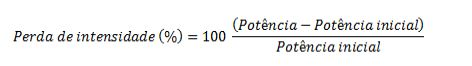
[035] Embora apenas a potência de emissão da substância fosforescente seja plotada, a potência integrada da emissão do laser, assim como a posição do pico do mesmo, foi monitorada para garantir que o laser permaneceu estável (variações de menos que 1%) durante o experimento.[035] Although only the emission power of the phosphor is plotted, the integrated power of the laser emission, as well as the peak position of the laser, was monitored to ensure that the laser remained stable (variations of less than 1%) during the experiment.
[036] As amostras para tratamento de alta temperatura e alta umidade (HTHH) foram feitas misturando-se pós de substância fosforescente em um ligante de metil silicone de duas partes (RTV-615, Momentive Performance Materials) a uma razão de 0,9 g de substância fosforescente para 0,825 g de silicone (partes A+B). A mistura de substância fosforescente/silicone é, então, vertida em suportes para amostra de alumínio e curada a 90 °C por 20 minutos. As amostras de controle foram armazenadas em nitrogênio e as amostras para exposição a condições de HTHH foram colocadas em uma câmara de atmosfera controlada a 85 °C/85% de RH. Essas amostras de HTHH foram removidas periodicamente e a intensidade de emissão de luz das mesmas sob excitação a 450 nm foi comparada com a das amostras de controle.[036] Samples for high temperature and high humidity (HTHH) treatment were made by mixing phosphor powders in a two-part methyl silicone binder (RTV-615, Momentive Performance Materials) at a ratio of 0.9 g of phosphor for 0.825 g of silicone (parts A+B). The phosphor/silicone mixture is then poured into aluminum sample racks and cured at 90°C for 20 minutes. Control samples were stored in nitrogen and samples for exposure to HTHH conditions were placed in a controlled atmosphere chamber at 85 °C/85% RH. These HTHH samples were periodically removed and their light emission intensity under excitation at 450 nm was compared with that of the control samples.
[037] Um precursor de fluorossilicato de potássio dopado com Mn (PFS: Mn), K2SiF6:Mn, que contém 0,68% em peso de Mn com base no peso total do material precursor, foi colocado em uma câmara de fornalha. A câmara de fornalha foi submetida a vácuo e foi preenchida com uma atmosfera que contém gás flúor e gás nitrogênio. A câmara foi, então, aquecida até a temperatura de recozimento desejada. Após manter pela quantidade de tempo desejada, a câmara foi resfriada até a temperatura ambiente. A mistura de flúor e nitrogênio foi submetida a vácuo, a câmara foi preenchida e purgada diversas vezes com nitrogênio para garantir a remoção completa do gás flúor antes abrir a câmara.[037] A Mn-doped potassium fluorosilicate (PFS:Mn) precursor, K2SiF6:Mn, which contains 0.68% by weight of Mn based on the total weight of the precursor material, was placed in a furnace chamber. The furnace chamber was subjected to a vacuum and was filled with an atmosphere containing fluorine gas and nitrogen gas. The chamber was then heated to the desired annealing temperature. After holding for the desired amount of time, the chamber was cooled to room temperature. The mixture of fluorine and nitrogen was subjected to vacuum, the chamber was filled and purged several times with nitrogen to ensure complete removal of the fluorine gas before opening the chamber.
[038] Para os Exemplos 1 a 5, a atmosfera na câmara foi composta de 20% de gás flúor e 80% de gás nitrogênio. Para o Exemplo 6, a atmosfera foi composta de 5% de gás flúor e 95% de gás nitrogênio. A temperatura de ponto de definição da fornalha e o tempo para um primeiro período de recozimento (T1 e t1) e a temperatura de ponto de definição da fornalha e o tempo para um segundo período de recozimento, se houver, (T2 e t2) são indicados na Tabela 1. Devido ao ajuste da fornalha e como a amostra é colocada em relação aos pares termoelétricos de controle na fornalha, as temperaturas de amostras reais na fornalha foram de 25 a 75 °C maiores que o ponto de definição da fornalha.[038] For Examples 1 to 5, the atmosphere in the chamber was composed of 20% fluorine gas and 80% nitrogen gas. For Example 6, the atmosphere was composed of 5% fluorine gas and 95% nitrogen gas. The furnace set point temperature and time for a first annealing period (T1 and t1) and the furnace set point temperature and time for a second annealing period, if any, (T2 and t2) are shown in Table 1. Due to furnace tuning and how the sample is placed relative to the control thermocouples in the furnace, actual sample temperatures in the furnace were 25 to 75 °C higher than the furnace set point.
[039] A estabilidade do precursor PFS:Mn, que tem % em peso de Mn que varia de 0,68 a 0,73% em peso, e da substância fosforescente produzida (Exemplo Comparativo 1) foi testada sob condições de alto fluxo de luz, e os resultados são mostrados na Tabela 1. Os materiais temperados experimentaram significativamente menos dano que os materiais que não foram tratados termicamente.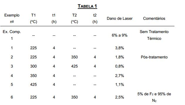
[040] O pó de substância fosforescente PFS temperado do Exemplo 2 foi tratado com uma solução saturada de K2SiF6 colocando-se o pó (~10 g) em um copo de precipitação de Teflon que continha 100 ml de uma solução saturada de K2SiF6 (feita inicialmente adicionando-se ~17 g de K2SiF6 em 40% de HF a temperatura ambiente, agitando-se e filtrando a solução). A suspensão foi lentamente agitada e o resíduo foi filtrado e seco a vácuo. A remoção adicional de HF do filtrado seco foi feita lavando-se em acetona por 3 a 5 vezes e aquecendo-se o filtrado a 100 °C por 10 min. A estabilidade da substância fosforescente submetida a pós-tratamento juntamente com uma amostra de PFS que não foi temperada mas foi submetida a pós-tratamento foi avaliada sob condições de HHTH, a 85 °C/85% de RH por 620 horas. A amostra submetida a pós-tratamento experimentou menos degradação sob as condições de alta temperatura/umidade, mantendo cerca de 94% de intensidade de emissão, enquanto a amostra não temperada manteve cerca de 86% de intensidade de emissão.[040] The tempered PFS phosphor powder from Example 2 was treated with a saturated solution of K2SiF6 by placing the powder (~10 g) in a Teflon precipitation beaker containing 100 ml of a saturated solution of K2SiF6 (made initially adding ~17 g of K2SiF6 in 40% HF at room temperature, stirring and filtering the solution). The suspension was slowly stirred and the residue was filtered and dried in vacuo. Further removal of HF from the dried filtrate was done by washing in acetone 3 to 5 times and heating the filtrate at 100 °C for 10 min. The stability of the post-treatment phosphor together with a PFS sample that was not quenched but subjected to post-treatment was evaluated under HHTH conditions, at 85°C/85% RH for 620 hours. The post-treatment sample experienced less degradation under the high temperature/humidity conditions, maintaining about 94% emission intensity, while the untempered sample maintained about 86% emission intensity.
[041] As amostras de precursores de PFS não temperados e não tratados, que têm conteúdo de Mn que varia de 0,5 a 0,85% em peso, foram testadas sob condições de alto fluxo de luz, conforme mostrado na Tabela 2.[041] Samples of unquenched and untreated PFS precursors, which have Mn content ranging from 0.5 to 0.85% by weight, were tested under high light flux conditions, as shown in Table 2.
[042] As amostras dos precursores de PFS foram temperadas a temperaturas de ponto de definição da fornalha que variam de 425 a 550 °C por tempos que variam de 4 a 8 horas, conforme mostrado na Tabela 2. Após recozimento, todas as amostras foram tratadas em soluções saturadas de K2SiF6 em 48% de HF, conforme no Exemplo 2. As substâncias fosforescentes temperadas foram testadas sob condições de alto fluxo de luz e os resultados são mostrados na Tabela 2.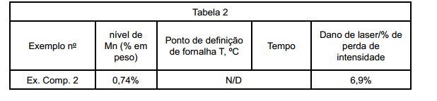

[043] O complexo K2SiF6:Mn (0,68% em peso de Mn) não temperado foi misturado com um precursor de silicone e feito na forma de uma fita sólida composta de 87,8% em volume de silicone e 12,2% em volume de PFS. Um controle continha uma mistura 1:1 de K2SiF6:Mn (0,68% em peso de Mn) (PFS dopado) e K2SiF6 (0 % em peso de Mn) (PFS não dopado), que tem uma composição final de 75,6% em volume de silicone, 12,2% de PFS não dopado e 12,2% em volume de PFS dopado.[043] The unquenched K2SiF6:Mn complex (0.68% by weight Mn) was mixed with a silicone precursor and made into a solid tape composed of 87.8% by volume of silicone and 12.2% by volume. on PFS volume. A control contained a 1:1 mixture of K2SiF6:Mn (0.68 wt% Mn) (doped PFS) and K2SiF6 (0 wt% Mn) (undoped PFS), which has a final composition of 75. 6% by volume silicone, 12.2% undoped PFS and 12.2% by volume doped PFS.
[044] A fita foi submetida a teste de estabilidade sob condições de alto fluxo de luz. A perda de intensidade de potência para a amostra de PFS diluída foi cerca de 2,5% após 24 horas e foi significativamente menor que a do controle.[044] The tape underwent stability testing under high light flux conditions. The loss of potency intensity for the diluted PFS sample was about 2.5% after 24 hours and was significantly lower than that of the control.
[045] Um precursor de fluorossilicato de potássio dopado com Mn (PFS:Mn), K2SiF6:Mn, que contém 0,53% em peso de Mn com base no peso total do material precursor foi testado sob condições de alto fluxo de luz e os resultados são mostrados na Tabela 3. O material que contém o menor nível de Mn experimentou significativamente menos dano que o controle que não foi tratado termicamente (Exemplo Comparativo 8).
[046] Um precursor de fluorossilicato de potássio dopado com Mn (PFS:Mn), K2SiF6:Mn, que contém 0,84% em peso de Mn com base no peso total do material precursor, foi temperado sob as condições mostradas na Tabela 4 em uma fornalha diferente cujas temperaturas de ponto de definição foram mais próximas da temperatura máxima na fornalha. Após a etapa de recozimento, os materiais foram processados com o uso do processo de pós- tratamento do Exemplo 2. A substância fosforescente e uma amostra temperada e não tratada (Exemplo Comparativo 9) foram testadas sob condições de alto fluxo de luz. Os resultados são mostrados na Tabela 4. O material temperado e submetido a pós-tratamento experimentou significativamente menos dano que o controle que não foi tratado termicamente. Além disso, a eficiência quântica da substância fosforescente sob excitação por LED azul foi maior em ~7,5% versus a amostra de controle inicial.[046] A Mn-doped potassium fluorosilicate (PFS:Mn) precursor, K2SiF6:Mn, which contains 0.84% by weight of Mn based on the total weight of the precursor material, was quenched under the conditions shown in Table 4 in a different furnace whose set point temperatures were closer to the maximum temperature in the furnace. After the annealing step, the materials were processed using the post-treatment process of Example 2. The phosphor and an untreated, quenched sample (Comparative Example 9) were tested under high light flux conditions. The results are shown in Table 4. The quenched and post-treated material experienced significantly less damage than the non-heat-treated control. Furthermore, the quantum efficiency of the phosphor under blue LED excitation was greater by ~7.5% versus the initial control sample.

[047] Os conjuntos de LED foram feitos com o uso de substâncias fosforescentes de K2SiF6:Mn4+ que foram temperadas com o uso das condições dos Exemplos 2 (Exemplo 16) e 5 (Exemplo 17), assim como as substâncias fosforescentes de K2SiF6:Mn4+ não temperadas (Exemplos Comparativos 10 e 11). Essas substâncias fosforescentes foram mescladas com granadas dopadas com Ce3+ e um ligante de silicone e depositadas dentro de um pacote similar a um conjunto de LED 3030 com dois circuitos integrados de LED emissor de azul para uma temperatura de cor de ~4000 K. Os pacotes foram, então, fixados a uma placa de circuito impresso. As dimensões do LED nesses pacotes foram de aproximadamente 0,65 mm x 0,65 mm; tomando essa área de LED, a densidade de corrente de LED é definida como: densidade de corrente de LED = corrente de acionamento/[(área de LED)*(número de LEDs no pacote)][047] The LED sets were made using K2SiF6:Mn4+ phosphors that were tempered using the conditions of Examples 2 (Example 16) and 5 (Example 17), as well as K2SiF6:Mn4+ phosphors. unseasoned (Comparative Examples 10 and 11). These phosphors were mixed with garnets doped with Ce3+ and a silicone binder and deposited inside a package similar to a 3030 LED array with two blue-emitting LED integrated circuits for ~4000 K color temperature. , then fixed to a printed circuit board. The LED dimensions in these packages were approximately 0.65mm x 0.65mm; taking this LED area, the LED current density is defined as: LED current density = drive current/[(LED area)*(number of LEDs in the package)]
[048] Os dispositivos do Exemplo Comparativo 10 e do Exemplo 16 foram operados a 30 mA, a temperatura ambiente (Tambient) de 47 °C por 4000 horas.[048] The devices of Comparative Example 10 and Example 16 were operated at 30 mA, at ambient temperature (Tambient) of 47 °C for 4000 hours.
[049] Os dispositivos do Exemplo Comparativo 11 e do Exemplo 17 foram operados a uma corrente de acionamento de 700 mA a uma temperatura de placa (Tboard) de 60 °C por 30 minutos. Usando a fórmula acima, uma corrente de acionamento de 30 mA fornece uma densidade de corrente de LED de aproximadamente 3,6 A/cm2, e uma corrente de acionamento de 700 mA fornece uma densidade de corrente de LED de aproximadamente 83 A/cm2. Conjuntos de LED similares sem substâncias fosforescentes fornecem uma eficiência de potência (definida pela potência óptica emitida dividida pela potência elétrica de entrada) de 54% a uma corrente de acionamento de 100 mA e uma temperatura de placa de 60 °C e 22% a uma corrente de acionamento de 700 mA e uma temperatura de placa de 60 °C. O ponto de cor do dispositivo foi obtido medindo-se a distribuição de potência espectral do dispositivo de LED que usa um espectrômetro de esfera integradora calibrado a tempos diferentes após a operação do LED sob diferentes condições de corrente de acionamento e temperatura ambiente/de placa. Os resultados são mostrados nas Tabelas 5 e 6.
[050] Embora apenas certos recursos da invenção tenham sido ilustrados e descritos no presente documento, muitas modificações e mudanças irão ocorrer aos elementos versados na técnica. Por esse motivo, deve ser entendido que as reivindicações anexas se destinam a cobrir todas essas modificações e mudanças que estejam dentro do espírito verdadeiro da invenção.[050] While only certain features of the invention have been illustrated and described herein, many modifications and changes will occur to those skilled in the art. For this reason, it is to be understood that the appended claims are intended to cover all such modifications and changes that are within the true spirit of the invention.
Claims (10)
Applications Claiming Priority (5)
| Application Number | Priority Date | Filing Date | Title |
|---|---|---|---|
| US201361791511P | 2013-03-15 | 2013-03-15 | |
| US61/791,511 | 2013-03-15 | ||
| US14/208,592 | 2014-03-13 | ||
| US14/208,592 US9698314B2 (en) | 2013-03-15 | 2014-03-13 | Color stable red-emitting phosphors |
| PCT/US2014/027733 WO2014152787A1 (en) | 2013-03-15 | 2014-03-14 | Color stable red-emitting phosphors |
Publications (2)
| Publication Number | Publication Date |
|---|---|
| BR112015022228A2 BR112015022228A2 (en) | 2017-07-18 |
| BR112015022228B1 true BR112015022228B1 (en) | 2022-03-15 |
Family
ID=51523627
Family Applications (1)
| Application Number | Title | Priority Date | Filing Date |
|---|---|---|---|
| BR112015022228-5A BR112015022228B1 (en) | 2013-03-15 | 2014-03-14 | Process for synthesizing a phosphor and lighting fixture |
Country Status (13)
| Country | Link |
|---|---|
| US (2) | US9698314B2 (en) |
| EP (2) | EP2970765B1 (en) |
| JP (2) | JP6392313B2 (en) |
| KR (2) | KR102461561B1 (en) |
| CN (2) | CN107482102B (en) |
| AU (6) | AU2014239197B2 (en) |
| BR (1) | BR112015022228B1 (en) |
| CA (1) | CA2905489C (en) |
| MX (1) | MX2015012735A (en) |
| MY (3) | MY172053A (en) |
| PH (1) | PH12015501963A1 (en) |
| TW (2) | TWI670359B (en) |
| WO (1) | WO2014152787A1 (en) |
Families Citing this family (81)
| Publication number | Priority date | Publication date | Assignee | Title |
|---|---|---|---|---|
| JP2014165225A (en) * | 2013-02-21 | 2014-09-08 | Toshiba Lighting & Technology Corp | Light-emitting module and illuminating device |
| US9580648B2 (en) | 2013-03-15 | 2017-02-28 | General Electric Company | Color stable red-emitting phosphors |
| US9868898B2 (en) * | 2013-03-15 | 2018-01-16 | General Electric Company | Processes for preparing color stable red-emitting phosphors |
| US9698314B2 (en) * | 2013-03-15 | 2017-07-04 | General Electric Company | Color stable red-emitting phosphors |
| US9399732B2 (en) * | 2013-08-22 | 2016-07-26 | General Electric Company | Processes for preparing color stable manganese-doped phosphors |
| US10230022B2 (en) | 2014-03-13 | 2019-03-12 | General Electric Company | Lighting apparatus including color stable red emitting phosphors and quantum dots |
| JP6094522B2 (en) * | 2014-04-10 | 2017-03-15 | 日亜化学工業株式会社 | Method for producing fluoride phosphor |
| US9546318B2 (en) * | 2014-05-01 | 2017-01-17 | General Electric Company | Process for preparing red-emitting phosphors |
| US9512356B2 (en) * | 2014-05-01 | 2016-12-06 | General Electric Company | Process for preparing red-emitting phosphors |
| US9567516B2 (en) * | 2014-06-12 | 2017-02-14 | General Electric Company | Red-emitting phosphors and associated devices |
| US9371481B2 (en) * | 2014-06-12 | 2016-06-21 | General Electric Company | Color stable red-emitting phosphors |
| US9385282B2 (en) * | 2014-06-12 | 2016-07-05 | General Electric Company | Color stable red-emitting phosphors |
| US9376615B2 (en) * | 2014-06-12 | 2016-06-28 | General Electric Company | Color stable red-emitting phosphors |
| US10563121B2 (en) * | 2014-06-12 | 2020-02-18 | Current Lighting Solutions, Llc | Red-emitting phosphors and associated devices |
| US9512357B2 (en) * | 2014-07-22 | 2016-12-06 | General Electric Company | Red-emitting phosphors, associated processes and devices |
| EP2988340B1 (en) * | 2014-08-18 | 2017-10-11 | Seoul Semiconductor Co., Ltd. | Light emitting diode package and manufacturing method thereof |
| TWI509844B (en) * | 2014-09-19 | 2015-11-21 | 東貝光電科技股份有限公司 | Applied to the backlight of the LED light-emitting structure |
| KR101809793B1 (en) | 2014-09-30 | 2017-12-15 | 니치아 카가쿠 고교 가부시키가이샤 | Fluoride fluorescent material, method for producing the same, and light emitting device |
| US10047286B2 (en) * | 2014-10-27 | 2018-08-14 | General Electric Company | Color stable red-emitting phosphors |
| JP2016088950A (en) * | 2014-10-30 | 2016-05-23 | 信越化学工業株式会社 | Red phosphor |
| JP6303980B2 (en) * | 2014-10-30 | 2018-04-04 | 信越化学工業株式会社 | Method for treating Mn-activated double fluoride phosphor |
| CA2967642C (en) * | 2014-11-21 | 2023-03-07 | General Electric Company | Color stable red-emitting phosphors |
| US9890328B2 (en) | 2014-12-12 | 2018-02-13 | General Electric Company | Phosphor compositions and lighting apparatus thereof |
| US9982190B2 (en) * | 2015-02-20 | 2018-05-29 | General Electric Company | Color stable red-emitting phosphors |
| TWI696726B (en) | 2015-03-05 | 2020-06-21 | 美商通用電機股份有限公司 | Red-emitting phosphors, processes and devices |
| JP2016204432A (en) * | 2015-04-16 | 2016-12-08 | 三菱化学株式会社 | Phosphor, light emitting device, lighting device, and image display device |
| JP5952938B1 (en) * | 2015-04-21 | 2016-07-13 | シャープ株式会社 | Light emitting device and image display device |
| US10174248B2 (en) | 2015-05-18 | 2019-01-08 | General Electric Company | Process for improved halide materials |
| CN118291130A (en) * | 2015-05-18 | 2024-07-05 | 卡任特照明解决方案有限责任公司 | Method for preparing MN-doped fluoride phosphors |
| JP6947643B2 (en) * | 2015-06-01 | 2021-10-13 | ゼネラル・エレクトリック・カンパニイ | Color-stable red-emitting phosphor |
| US9871173B2 (en) | 2015-06-18 | 2018-01-16 | Cree, Inc. | Light emitting devices having closely-spaced broad-spectrum and narrow-spectrum luminescent materials and related methods |
| JP2018526471A (en) * | 2015-06-23 | 2018-09-13 | ゼネラル・エレクトリック・カンパニイ | Phosphor composition and lighting device thereof |
| TWI598538B (en) * | 2015-07-31 | 2017-09-11 | 宏齊科技股份有限公司 | Portable light-emitting device without using pre-storage power supply and LED package structure thereof |
| JP6222288B2 (en) * | 2015-08-07 | 2017-11-01 | 日亜化学工業株式会社 | Method for producing β-sialon phosphor |
| US11901492B2 (en) | 2015-09-10 | 2024-02-13 | Intematix Corporation | High color rendering white light emitting devices and high color rendering photoluminescence compositions |
| EP3347924A4 (en) * | 2015-09-10 | 2019-04-10 | Intematix Corporation | PHOSPHORUS-CONVERTED WHITE LIGHT EMITTING DEVICES AND PHOTOLUMINESCENCE COMPOUNDS FOR GENERAL LIGHTING AND DISPLAY BACKLIGHT |
| FR3043687B1 (en) * | 2015-11-13 | 2020-07-03 | Universite Blaise Pascal Clermont Ii | SOL-GEL PROCESS FOR THE SYNTHESIS OF A LUMINESCENT MATERIAL OF GENERAL FORMULATION AXBYFZ: MN |
| JP7067857B2 (en) | 2015-11-17 | 2022-05-16 | 株式会社東芝 | A fluorescent substance, a method for producing the same, and a light emitting device using the fluorescent substance. |
| CN108291142B (en) * | 2015-11-26 | 2021-03-12 | 卡任特照明解决方案有限责任公司 | Methods for synthesizing red-emitting phosphors and red-emitting phosphors |
| CN108473866A (en) | 2015-12-18 | 2018-08-31 | 三菱化学株式会社 | Phosphor, light emitting device, lighting device and image display device |
| KR102530756B1 (en) | 2016-01-13 | 2023-05-10 | 삼성전자주식회사 | Fluoride phosphor, manufacturing method of the same, and light emitting device |
| JP6443417B2 (en) * | 2016-02-29 | 2018-12-26 | 日亜化学工業株式会社 | Nitride phosphor manufacturing method, nitride phosphor and light emitting device |
| US10754081B2 (en) | 2016-03-07 | 2020-08-25 | Current Lighting Solutions, Llc | Devices containing a remote phosphor package with red line emitting phosphors and green emitting quantum dots |
| US10851293B2 (en) * | 2016-04-14 | 2020-12-01 | Current Lighting Solutions, Llc | Phosphor materials for light sources and method for manufacturing the same |
| US10883045B2 (en) * | 2016-05-02 | 2021-01-05 | Current Lighting Solutions, Llc | Phosphor materials including fluidization materials for light sources |
| EP3455327A1 (en) * | 2016-05-09 | 2019-03-20 | General Electric Company | Manganese-doped phosphor materials for high power density applications |
| WO2017210080A1 (en) * | 2016-06-02 | 2017-12-07 | General Electric Company | Red-emitting phosphors and associated devices |
| KR20190022798A (en) | 2016-06-27 | 2019-03-06 | 제네럴 일렉트릭 컴퍼니 | Coated manganese doping phosphor |
| US10072206B2 (en) * | 2016-06-30 | 2018-09-11 | General Electric Company | Processes for preparing color stable red-emitting phosphors |
| US9929321B2 (en) * | 2016-08-04 | 2018-03-27 | Kabushiki Kaisha Toshiba | Phosphor, producing method thereof and light-emitting device employing the phosphor |
| US10193030B2 (en) | 2016-08-08 | 2019-01-29 | General Electric Company | Composite materials having red emitting phosphors |
| US11114591B2 (en) * | 2016-08-17 | 2021-09-07 | Current Lighting Solutions, Llc | Core-shell materials with red-emitting phosphors |
| US11702348B2 (en) | 2016-08-19 | 2023-07-18 | Current Lighting Solutions, Llc | Purified potassium hexafluoromanganate and methods for purifying potassium hexafluoromanganate |
| EP3538624A1 (en) | 2016-10-12 | 2019-09-18 | Merck Patent GmbH | Mn4+-activated luminescence material as conversion luminescent material for led solid state light sources |
| CN110072970B (en) * | 2016-11-17 | 2022-07-05 | 卡任特照明解决方案有限公司 | Coated red line emitting phosphor |
| US11193059B2 (en) | 2016-12-13 | 2021-12-07 | Current Lighting Solutions, Llc | Processes for preparing color stable red-emitting phosphor particles having small particle size |
| US10793773B2 (en) | 2017-03-16 | 2020-10-06 | Current Lighting Solutions, Llc | Color stable red-emitting phosphors |
| CA3063060A1 (en) * | 2017-04-12 | 2018-10-18 | Current Lighting Solutions, Llc | Devices containing a remote phosphor package with red line emitting phosphors and green emitting quantum dots |
| CN107033891B (en) * | 2017-06-13 | 2019-07-16 | 温州大学 | A kind of red light material for white light LED based on fluorozirconate and preparation method thereof |
| US20190048258A1 (en) * | 2017-08-10 | 2019-02-14 | General Electric Company | Coated manganese doped phosphors |
| JP2019044018A (en) * | 2017-08-30 | 2019-03-22 | デンカ株式会社 | Fluoride phosphors and light emitting devices |
| JP2019044017A (en) * | 2017-08-30 | 2019-03-22 | デンカ株式会社 | Fluoride phosphors and light emitting devices |
| CN109423276B (en) * | 2017-09-05 | 2022-03-15 | 厦门稀土材料研究所 | A kind of efficient and stable Mn4+ doped fluoride light-emitting material and preparation method thereof |
| WO2019054979A1 (en) | 2017-09-12 | 2019-03-21 | General Electric Company | Processes for preparing color stable red-emitting phosphors |
| WO2019054986A1 (en) | 2017-09-12 | 2019-03-21 | General Electric Company | Processes for preparing color stable red-emitting phosphors |
| US10541353B2 (en) | 2017-11-10 | 2020-01-21 | Cree, Inc. | Light emitting devices including narrowband converters for outdoor lighting applications |
| EP4047072B1 (en) | 2018-03-20 | 2023-12-13 | LITEC-Vermögensverwaltungsgesellschaft mbH | Light source with luminescent material |
| CN111057535A (en) * | 2018-10-16 | 2020-04-24 | 云南民族大学 | Mn (manganese)4+Preparation method of doped fluoride homogeneous-coated red luminescent crystal |
| DE102018218159B4 (en) * | 2018-10-24 | 2024-01-25 | OSRAM Opto Semiconductors Gesellschaft mit beschränkter Haftung | RED FLUORESCENT, METHOD FOR PRODUCING A FLUORESCENT AND CONVERSION LED |
| US11862758B2 (en) | 2018-11-28 | 2024-01-02 | Lawrence Livermore National Security, Llc | Systems and methods for fluoride ceramic phosphors for LED lighting |
| JP6821133B2 (en) * | 2018-12-20 | 2021-01-27 | 日亜化学工業株式会社 | Method for producing fluoride phosphor |
| US11261375B2 (en) | 2019-05-22 | 2022-03-01 | General Electric Company | Method to enhance phosphor robustness and dispersability and resulting phosphors |
| CN110429167B (en) * | 2019-07-17 | 2020-12-08 | 武汉大学 | LED packaging method to achieve high spatial color uniformity |
| EP4136177A4 (en) | 2020-04-14 | 2024-07-24 | General Electric Company | INK COMPOSITIONS AND FILMS CONTAINING NARROW-BAND EMITTING LUMINOPHORIC MATERIALS |
| EP4136187A4 (en) | 2020-04-14 | 2024-06-19 | General Electric Company | GREEN-EMITTING PHOSPHORES AND ASSOCIATED DEVICES |
| EP4208521A4 (en) | 2020-09-01 | 2024-10-09 | General Electric Company | NIGHT VISION COMPATIBLE DEVICES |
| JP7057530B2 (en) * | 2020-12-21 | 2022-04-20 | 日亜化学工業株式会社 | Method for producing fluoride phosphor |
| TW202249302A (en) | 2021-04-13 | 2022-12-16 | 美商奇異電器公司 | Uranium-based phosphors and compositions for displays and lighting applications |
| US12018194B2 (en) | 2021-08-20 | 2024-06-25 | Seoul Semiconductor Co., Ltd. | Color stable Mn-activated oxidofluorides as conversion luminescent materials for LED-based solid state light sources |
| US20230279292A1 (en) * | 2022-03-04 | 2023-09-07 | Seoul Semiconductor Co., Ltd. | NOVEL Mn(VI) - ACTIVATED OXIDOFLUORIDES AS LUMINESCENT MATERIALS FOR SOLID STATE LIGHT SOURCES |
| WO2025178920A1 (en) | 2024-02-19 | 2025-08-28 | Edison Innovations, Llc | Devices including reflective geometries for displays and lighting applications |
Family Cites Families (50)
| Publication number | Priority date | Publication date | Assignee | Title |
|---|---|---|---|---|
| US2522074A (en) | 1946-05-03 | 1950-09-12 | Univ Rochester | Method of rendering infrared radiation visible employing doubly activated alkaline earth sulfide phosphors |
| US3576756A (en) | 1968-06-12 | 1971-04-27 | Mallinckrodt Chemical Works | Fluocomplexes of titanium, silicon, tin and germanium, activated by tetravalent manganese |
| GB1360690A (en) | 1973-02-16 | 1974-07-17 | Gen Electric Co Ltd | Luminescent materials |
| US4479886A (en) | 1983-08-08 | 1984-10-30 | Gte Products Corporation | Method of making cerium activated yttrium aluminate phosphor |
| US6103296A (en) | 1998-04-22 | 2000-08-15 | Osram Sylvania Inc. | Method for improving the screen brightness of gadolinium oxysulfide x-ray phosphors |
| CN1157462C (en) | 2002-04-15 | 2004-07-14 | 清华大学 | Nano-class conversion fluorescence material on fluoride matrix and its preparing process |
| US6800373B2 (en) * | 2002-10-07 | 2004-10-05 | General Electric Company | Epoxy resin compositions, solid state devices encapsulated therewith and method |
| RU2359916C2 (en) | 2004-09-10 | 2009-06-27 | Шоува Денко К.К. | Method for preparation of manganese fluoride |
| US7270773B2 (en) | 2005-01-10 | 2007-09-18 | General Electric Company | Quantum-splitting fluoride-based phosphors, method of producing, and radiation sources incorporating same |
| US7358542B2 (en) | 2005-02-02 | 2008-04-15 | Lumination Llc | Red emitting phosphor materials for use in LED and LCD applications |
| US7497973B2 (en) | 2005-02-02 | 2009-03-03 | Lumination Llc | Red line emitting phosphor materials for use in LED applications |
| US7648649B2 (en) * | 2005-02-02 | 2010-01-19 | Lumination Llc | Red line emitting phosphors for use in led applications |
| TWI389337B (en) | 2005-05-12 | 2013-03-11 | 松下電器產業股份有限公司 | Light-emitting device, display device and illumination device using same, and method of manufacturing the same |
| EP1892268B1 (en) | 2005-06-14 | 2015-10-28 | Denki Kagaku Kogyo Kabushiki Kaisha | Resin composition and sheet containing phosphor, and light emitting element using such composition and sheet |
| US7834541B2 (en) * | 2006-10-05 | 2010-11-16 | Global Oled Technology Llc | OLED device having improved light output |
| EP2141215A4 (en) | 2007-03-30 | 2011-11-30 | Mitsubishi Chem Corp | PHOSPHOR AND METHOD FOR PRODUCING THE SAME, PHOSPHORUS-CONTAINING COMPOSITION, LIGHT-EMITTING DEVICE, IMAGE DISPLAY DEVICE, AND LIGHTING DEVICE |
| WO2009005035A1 (en) | 2007-06-29 | 2009-01-08 | Mitsubishi Chemical Corporation | Phosphor, method for producing phosphor, phosphor-containing composition, and light-emitting device |
| US7847309B2 (en) | 2007-07-16 | 2010-12-07 | GE Lighting Solutions, LLC | Red line emitting complex fluoride phosphors activated with Mn4+ |
| US8137586B2 (en) * | 2007-09-14 | 2012-03-20 | Osram Sylvania Inc. | Phosphor blend for a compact fluorescent lamp and lamp containing same |
| EP3045965B1 (en) | 2008-02-07 | 2020-05-27 | Mitsubishi Chemical Corporation | Red emitting fluoride phosphor activated by mn4+ |
| US8237348B2 (en) | 2008-03-03 | 2012-08-07 | Sharp Kabushiki Kaisha | Light-emitting device |
| JP5545665B2 (en) | 2008-03-25 | 2014-07-09 | 国立大学法人群馬大学 | Method for manufacturing phosphor |
| JP5239043B2 (en) * | 2008-07-18 | 2013-07-17 | シャープ株式会社 | Light emitting device and method for manufacturing light emitting device |
| JP5682104B2 (en) * | 2008-09-05 | 2015-03-11 | 三菱化学株式会社 | Phosphor and method for producing the same, phosphor-containing composition and light emitting device using the phosphor, and image display device and lighting device using the light emitting device |
| JP2010093132A (en) | 2008-10-09 | 2010-04-22 | Sharp Corp | Semiconductor light emitting device, and image display and liquid crystal display using the same |
| US8703016B2 (en) | 2008-10-22 | 2014-04-22 | General Electric Company | Phosphor materials and related devices |
| WO2011073871A2 (en) | 2009-12-17 | 2011-06-23 | Koninklijke Philips Electronics N.V. | Light emitting diode device with luminescent material |
| TW201140890A (en) | 2009-12-17 | 2011-11-16 | Koninkl Philips Electronics Nv | Lighting device with light source and wavelength converting element |
| US8593062B2 (en) | 2010-04-29 | 2013-11-26 | General Electric Company | Color stable phosphors for LED lamps and methods for preparing them |
| US8057706B1 (en) * | 2010-07-27 | 2011-11-15 | General Electric Company | Moisture-resistant phosphor and associated method |
| US8210698B2 (en) | 2010-07-28 | 2012-07-03 | Bridgelux, Inc. | Phosphor layer having enhanced thermal conduction and light sources utilizing the phosphor layer |
| CN102986044B (en) | 2010-10-15 | 2015-05-06 | 三菱化学株式会社 | White light-emitting devices and lighting fixtures |
| US8252613B1 (en) | 2011-03-23 | 2012-08-28 | General Electric Company | Color stable manganese-doped phosphors |
| MY167700A (en) | 2011-04-08 | 2018-09-21 | Shinetsu Chemical Co | Preparation of complex fluoride and complex fluoride phosphor |
| JP5418548B2 (en) | 2011-07-06 | 2014-02-19 | 日亜化学工業株式会社 | Fluoride phosphor and light emitting device using the fluoride phosphor |
| JP5375906B2 (en) | 2011-09-13 | 2013-12-25 | 日亜化学工業株式会社 | Fluoride phosphor and light emitting device using the same |
| KR101535164B1 (en) | 2011-12-16 | 2015-07-09 | 코닌클리케 필립스 엔.브이. | Mn-activated hexafluorosilicates for led applications |
| CN104114671B (en) | 2012-02-16 | 2016-10-26 | 皇家飞利浦有限公司 | Coated narrow-band red-emitting fluorosilicates for semiconductor LEDs |
| WO2013138347A1 (en) | 2012-03-12 | 2013-09-19 | Nitto Denko Corporation | Emissive compacts and method of making the same |
| JP5840540B2 (en) | 2012-03-15 | 2016-01-06 | 株式会社東芝 | White lighting equipment |
| US9343613B2 (en) | 2012-03-29 | 2016-05-17 | Koninklijke Philips N.V. | Phosphor in inorganic binder for LED applications |
| WO2013158929A1 (en) | 2012-04-18 | 2013-10-24 | Nitto Denko Corporation | Phosphor ceramics and methods of making the same |
| CN102719242B (en) * | 2012-05-29 | 2014-12-03 | 温州大学 | A kind of fluoride-containing Mn4+ doped red light material and preparation method thereof |
| CN102827601B (en) | 2012-09-17 | 2014-08-20 | 中国科学院福建物质结构研究所 | Fluoride fluorescent powder material and semiconductor light-emitting device thereof |
| CN102851026B (en) | 2012-10-15 | 2014-07-02 | 温州大学 | Red light material for bi-primary-color white light LEDs (light-emitting diodes) and preparation method thereof |
| KR20150082426A (en) | 2012-11-01 | 2015-07-15 | 코닌클리케 필립스 엔.브이. | Led-based device with wide color gamut |
| US9698314B2 (en) * | 2013-03-15 | 2017-07-04 | General Electric Company | Color stable red-emitting phosphors |
| US20150069299A1 (en) | 2013-09-11 | 2015-03-12 | Nitto Denko Corporation | Phosphor Ceramics and Methods of Making the Same |
| JP6094532B2 (en) * | 2013-12-27 | 2017-03-15 | 日亜化学工業株式会社 | Method for producing fluoride phosphor |
| JP5804149B2 (en) * | 2014-01-30 | 2015-11-04 | 信越化学工業株式会社 | Manufacturing method and processing method of double fluoride phosphor |
-
2014
- 2014-03-13 US US14/208,592 patent/US9698314B2/en active Active
- 2014-03-14 CA CA2905489A patent/CA2905489C/en active Active
- 2014-03-14 MY MYPI2015002135A patent/MY172053A/en unknown
- 2014-03-14 KR KR1020217014938A patent/KR102461561B1/en active Active
- 2014-03-14 EP EP14720825.0A patent/EP2970765B1/en active Active
- 2014-03-14 CN CN201710706690.6A patent/CN107482102B/en active Active
- 2014-03-14 TW TW107117538A patent/TWI670359B/en active
- 2014-03-14 EP EP19160916.3A patent/EP3572480A1/en active Pending
- 2014-03-14 JP JP2016502530A patent/JP6392313B2/en active Active
- 2014-03-14 MX MX2015012735A patent/MX2015012735A/en unknown
- 2014-03-14 AU AU2014239197A patent/AU2014239197B2/en active Active
- 2014-03-14 KR KR1020157029868A patent/KR102255496B1/en active Active
- 2014-03-14 TW TW103109499A patent/TWI629340B/en active
- 2014-03-14 BR BR112015022228-5A patent/BR112015022228B1/en active IP Right Grant
- 2014-03-14 MY MYPI2018002205A patent/MY187622A/en unknown
- 2014-03-14 MY MYPI2018002206A patent/MY189440A/en unknown
- 2014-03-14 WO PCT/US2014/027733 patent/WO2014152787A1/en not_active Ceased
- 2014-03-14 CN CN201480028317.4A patent/CN105189696B/en active Active
- 2014-06-23 US US14/311,624 patent/US8906724B2/en active Active
-
2015
- 2015-09-04 PH PH12015501963A patent/PH12015501963A1/en unknown
-
2017
- 2017-01-06 AU AU2017200092A patent/AU2017200092B2/en active Active
-
2018
- 2018-02-16 JP JP2018025677A patent/JP7094715B2/en active Active
- 2018-08-13 AU AU2018217203A patent/AU2018217203A1/en not_active Abandoned
-
2020
- 2020-07-27 AU AU2020210150A patent/AU2020210150A1/en not_active Abandoned
-
2022
- 2022-04-29 AU AU2022202852A patent/AU2022202852A1/en not_active Abandoned
-
2024
- 2024-06-06 AU AU2024203857A patent/AU2024203857A1/en active Pending
Also Published As
Similar Documents
| Publication | Publication Date | Title |
|---|---|---|
| BR112015022228B1 (en) | Process for synthesizing a phosphor and lighting fixture | |
| US11851595B2 (en) | Color stable red-emitting phosphors | |
| AU2015202034B2 (en) | Process for preparing red-emitting phosphors | |
| CA2951717C (en) | Color stable red-emitting phosphors | |
| CA2952250C (en) | Color stable red-emitting phosphors | |
| CA2967642C (en) | Color stable red-emitting phosphors |
Legal Events
| Date | Code | Title | Description |
|---|---|---|---|
| B06F | Objections, documents and/or translations needed after an examination request according [chapter 6.6 patent gazette] | ||
| B06U | Preliminary requirement: requests with searches performed by other patent offices: procedure suspended [chapter 6.21 patent gazette] | ||
| B07A | Application suspended after technical examination (opinion) [chapter 7.1 patent gazette] | ||
| B09A | Decision: intention to grant [chapter 9.1 patent gazette] | ||
| B16A | Patent or certificate of addition of invention granted [chapter 16.1 patent gazette] |
Free format text: PRAZO DE VALIDADE: 20 (VINTE) ANOS CONTADOS A PARTIR DE 14/03/2014, OBSERVADAS AS CONDICOES LEGAIS. |