Academia.edu no longer supports Internet Explorer.
To browse Academia.edu and the wider internet faster and more securely, please take a few seconds to upgrade your browser.
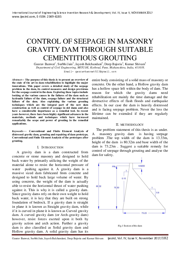
— The purpose of this thesis is to present an overview of the state of the art in dam rehabilitation to highlight the major innovations. This paper covers a detailed study of the seepage problem in the dam, its control measures and design provisions for the seepage control in the dam. Exploring these topics include looking at the various causes in the failures of the dam such as hydraulic failure of the dam, seepage failure and the structural failure of the dam. Also explaining the various grouting techniques which are the integral part of the new dam construction as well as control of seepage in old dams and also have a considerable importance as a remedial tool. In recent years however, there have been highly significant advances in the materials, methods and techniques which have increased remarkably the scope and power of grouting in the remedial applications. Keywords— Conventional and Finite Element Analysis of distressed gravity dam, grouting and repairing of dam prototype, Conventional and Finite Element Analysis of the prototypes after grouting.
One of the major concerns facing dam is the repair of their structures to prevent the seepage under them. In previous years, many existing dams have been treated by grouting, but with varying degrees of success. One of the major reasons for this erratic performance is the unsuitable selection of the grouting materials to reduce the seepage. Grouting is an effective way to strengthen of the permeability of the soil to reduce the seepage. The purpose of this paper is to focus on the efficiency of current available grouting materials and techniques from construction, environmental and economical point of view. The seepage reduction usually accomplished by either chemical grouting o r cementious grouting using ultrafine cement. In addition, the study shows a comparison between grouting materials according to their degree of permeability reduction and cost. The application of seepage reduction is based on the permeation grouting using grout curtain installation. The computer program (SEEP/W) is employed to model a dam rested on sandy soil, using grout curtain to reduce seepage quantity and hydraulic gradient by different grouting materials. This study presents a relationship that takes into account the permeability of the soil, grout curtain spacing and a new performance parameter that can be used to predict the best selection of grouting materials for seepage reduction
2017 •
Indian Journal of Fundamental and Applied Life Sciences
The Study of Cement Grouting on the Improvement of Darband Dam Structure of Bojnord-Iran2014 •
Proceedings of the VI International Conference on Structural Analysis of Historic Construction, SAHC08, 2-4 July 2008, Bath, United Kingdom
Methodology for in situ application of hydraulic grouts on historic masonry structures. The case of the Katholikon of Dafni Monastery2008 •
Grouting is one of the most popular methods used to control water leaking in fill dam constructions. Geological and geotechnical properties of the rock/soil to be grouted are important parameters influencing the design of the grouting. In this study, geotechnical properties of Cindere dam’s base rock and the grouting procedure have been investigating view of suitability to grouting. Detailed investigations of the foundation injection applications made into the main rock, the reasons and types of application are made. The materials used in grouting and the grouting pressures are investigated at site and the obtained results are presented. The improvement study and application type is evaluated and background information on different applications of grouting is presented. Key words: Grouting dam, Cindere dam, imperviousness.
International Journal of Physical Sciences
An application of grout curtains to the Dalaman -Akkpr Dam2011 •
Using ointments as an eye drug delivery system gives topical therapy a significant new aspect. Ointments are a great way to increase ocular contact duration and are generally safe and welltolerated. Increased contact time results in higher drug levels in the eyes. Experimental evidence, however, suggests that corticosteroid ointments do not enter the eye as deeply as suspension solutions do. This could be related to both the specific steroid component and the drug's binding to the ointment base. Ointments can get contaminated, just like other ophthalmic preparations. It is not recommended to apply ophthalmic ointments to eyes that have open sores. It seems safe and effective to apply ointments to postoperative eyes where wound closure is secure.
Social Development Issues
Social Development: Synthesizing Theory and Practice2024 •
This paper traces the trajectory of my thinking on social development shaped, initially, by the huge changes that swept South Africa in the 1990s. It describes my early focus on discerning what the policy-driven changes to a developmental welfare system meant for social work and the subsequent critical turn, as social development proved extremely difficult to translate to practice. It traces the changes in my thinking on coming to Australia in 1999, when the country was undergoing a period of massive welfare reform, firmly embedding neoliberal privatization policy. In reflecting on switching concepts in the social development discourse, the discussion turns to its embrace of neoliberalism. Thereafter, it considers three models to highlight the turn from centralized planning, which held the government responsible for social development, to social enterprise, which divested government of its responsibility, and a critical development model that linked national policy to the wider international system. Noting critiques of neoliberal social development, the discussion ends with the current trajectory of my thinking outlined in a critical model for developmental practice with the core foci being the structural-political, cultural-contextual, critical-developmental, and environmental-spiritual dimensions of social development.
European Journal of Empirical Legal Studies
The Empirical Foundation of Normative Arguments in Legal Reasoning2024 •
Quantitative empirical legal studies are often challenged by traditional doctrinal legal scholars as irrelevant to normative legal reasoning. This essay explores, through the lens of jurisprudence and by drawing on dozens of empirical works, the junction between empirical facts and normative arguments. Teleological and consequential arguments, both of which are prevalent in normative legal reasoning, employ "differencemaking facts" as one of their premises, which states the causal effects of certain legal measures and can be identified by causal inference in empirical research. All causal-identifying empirical findings thus constitute an essential part of teleological and consequential arguments for or against a normative claim. Finally, although some classical canons of legal interpretation, such as textual and systematic interpretations, appear not to take the form of teleological or consequential arguments, the use of these specific legal arguments must nonetheless be justified by teleological or consequential arguments at the meta-level. Thus, normative legal reasoning, one way or another, must have empirical foundations.
2021 •
Biochemical Journal
Respective influences of age and weaning on skeletal and visceral muscle protein synthesis in the lamb1988 •
2023 •
2017 •
Български език
The Old Bulgarian Demonstrative Pronoun сь as a Subordinate Element in the Verb Group and its Equivalents in Old English2023 •
Sexualidad, Salud y Sociedad
Significados Acerca De La Sexualidad en Estudiantes De Psicología en Colombia2015 •
Water
A Hydrological and Geomorphometric Approach to Understanding the Generation of Wadi Flash Floods2017 •
Physical review
Electronic Mechanism for Production of Self-Phase Modulation1972 •
Revista de la Asociación Española de Especialistas en Medicina del Trabajo
Consumo de alcohol cuantificado versus percibido en trabajadores españoles2018 •
 IJESIRD journal