Proceedings of the 7th International Conference on Civil, Structural and Transportation Engineering (ICCSTE'22)
Niagara Falls, Canada – June 05-07, 2022
Paper No. 210
DOI: 10.11159/iccste22.210
Composite Cold-Formed Steel Rubberised Concrete Building
Framed Systems
Dieudonne Iraguha1, Derya Deniz2, Alireza Bagheri Sabbagh3, Shahabeddin Torabian4, Naeimeh
Jafarifar5
Department of Civil Engineering, Özyeğin University, Istanbul, Turkey, dieudonne.iraguha@ozu.edu.tr
Department of Civil Engineering, Özyeğin University, Istanbul, Turkey, derya.deniz@ozyegin.edu.tr
3
School of Engineering, University of Aberdeen, Scotland, UK, alireza.bsabbagh@abdn.ac.uk
4
Department of Civil and Systems Engineering, Johns Hopkins University, Baltimore, MD, USA, storabian@sgh.com
5
School of Architecture and Built Environment, Robert Gordon University, Aberdeen, Scotland, UK, n.jafarifar@rgu.ac.uk
1
2
Abstract - In this research, with the use of cold-formed steel (CFS) sections in-filled with rubberized concrete (RuC), a new low-carbon
construction system is developed and assessed for its structural resilience and environmental impact compared to the current conventional
earthquake-proof construction. First, connection level moment-rotation responses of the new form of CFS-RuC framed structure are
validated against the results obtained from detailed finite element analyses. Next, nonlinear pushover analyses are undertaken on the
CFS-RuC framed system in conjunction with conventional hot-rolled steel and reinforced-concrete (RC) frames for a case study selected
in Istanbul. Lastly, economic and environmental impact analyses are conducted on the frame systems. The results show that the new
CFS-RuC composite system offers both structural and environmental advantages compared to conventional systems. In terms of seismic
performance of multi-storey buildings, it is shown that the ductility capacity of the CFS-RuC system can be improved by increasing the
number of stories.
Keywords: Rubberized concrete, Cold-formed Steel, Carbon footprint, Semi-rigid connections, Seismic performance.
1. Introduction
Given both the high seismicity of Turkey’s most populated city, Istanbul and its prominent role in commercial and
cultural activities, an urgent need has arisen to seek sustainable mitigation plans to reduce the devastating effects of probable
future earthquakes in this city. Most importantly, in the face of global climate emergencies, plans to be adopted should ensure
that drastic reductions in carbon emissions are a priority. Therefore, while preparing for disasters, many efforts should be
invested in addressing carbon emissions associated with the construction process.
Presently, the industrial sectors responsible for 25% of the global CO 2 focus on minimizing the use of virgin materials
by increasing the use of recycled materials, which are destined to be stockpiled if not recycled. Recently, the potential of
using rubber from scrap tires in the construction sector has been studied [1]. Studies show that adding rubber to normal
concrete results in more energy-dissipative concrete with increased ductility [2], which is desirable in high seismic zones
like Istanbul. In addition to their high performance, concrete composites which utilize recycled tires as aggregates have the
potential to reduce overall greenhouse gas emissions, provide potential economic benefit and reduce the environmental issues
associated with end-of-life tires as compared to conventional concrete [1]. Moreover, seismic shaking table tests demonstrate
that adding rubber crumbs can reduce the seismic force on concrete structures due to the increased damping, therefore
permitting designs with fewer materials. At the same time, concerns about the reduction in compressive strength of
rubberized concrete have been raised, which is attributed to the poor bonding between the rubber particles and the cement
paste [2].
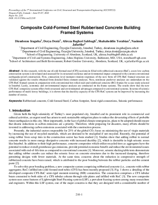
To solve this poor bonding problem, a new composite system comprising rubberized concrete (i.e., concrete with rubber
aggregates; RuC) infilled into cold-formed steel tubes (CFS) has been recently proposed [3]. Fig. 1 shows a detailing of the
developed composite CFS-RuC semi-rigid moment-resisting (MR) connection. The connection comprises a CFS tubular
beam connected to both sides of a CFS tubular column through side plates and infilled with RuC [3]. The new composite
system uses some features of Lightweight Steel Framing system (LSF), a prevalent framing system among many researchers
and engineers. Within this LSF system, one of the major concerns is that they are designed with a considerable number of
210-1
�underutilized sections [4]. To address this issue, the role played by connection configurations is critical in facilitating full
strength usage of LSF sections and improving the ductility capacity. Therefore, an earlier study by the authors has focused
on detailed finite element (FE) analyses of various connection configurations of the rubberized concrete-filled steel tube
sections (CFS-RuC) [3]. Using these FE results [3], this paper extends the work and explores its applicability to the frame
level analysis by conducting a validation study.
Fig.1: Details of the rubberized concrete-filled steel tube system (adopted from [3])
This paper first develops a practical plastic hinge model (i.e., moment versus rotation) representing the performance of
the new frame system’s connection (Fig.1) through a validation study. Then, frame-level performance analyses are conducted
on different frame structures using the developed connection model and results from the validation study. Eventually, an
economic/environmental impact assessment is implemented to evaluate the low carbon sustainability of the new composite
system. Among anticipated advantages of this new system, when compared to conventional steel or reinforced concrete
systems, include the following: the restraining effect of rubberized concrete makes the local buckling of the steel tube
postponed and mitigates the strength deterioration after local buckling, therefore enhancing energy dissipation capacity in
the post-yield response. In addition, the environmental burden can be reduced by omitting formwork and bypassing the
extraction of virgin aggregates; hence CO2 emitting actions involved in acquiring those aggregates are avoided. Moreover,
potential fire threats and pollution caused by stockpiles of rubber shreds can be avoided by storing these materials as
aggregates inside the RuC members.
2. Plastic Hinge Model for CFS-RuC Connections
The finite element (FE) results obtained in the earlier study [3] provide a basis for justifying the practicality of the infill
RuC in eliminating unwanted limit states and improving the moment-rotation response. However, finite element analyses
[3] require too much computation effort and hence are not practical to perform frame-level analyses. A plastic hinge model
is therefore developed through a validation study with the corresponding FE results to come up with an applicable modeling
protocol that can be used in the frame-level analysis.
In this study, connection configurations are labeled with abbreviations that start with CFS-RuC, then the beam and
column thicknesses (2, 3, or 4 mm) respectively, followed by side plate thicknesses (SP4, 6, or 8 mm) and the number of
screw connection arrays (#15, 24, 36 or 42) ended by corresponding gravity loading (60, 300, 600 kN) considered in the
connection design. For example, CFSRuC2-4-SP4#24-300 stands for a CFS-RuC connection with a CFS beam thickness of
2 mm and a CFS column thickness of 4mm, using a side plate thickness of 4mm with 24 screws and 300 kN of gravity
loading applied at top of the column. Totally fifteen different connection configurations are considered in the study.
A shell type FE model using Abaqus [6] developed in the earlier study [3] and a corresponding beam type model using
SAP2000 [5] developed in this study are shown in Fig. 2a and Fig. 2b, respectively. The models represent a one-way
210-2
�cantilever connection component delineated between the inflection points of a 4 m span moment-frame under unity
displacement-controlled loading. In the SAP2000 model (Fig. 2b), the beam and column composite sections are modeled in
the section designer by assuming the unconfined concrete model for the RuC infill. Frame elements are used to model the
beams and columns. A hinge model composed of a plastic and an elastic spring element incorporating total moment(M)rotation(θ) response for the connection is modeled at the beam-column ends using M- θ curve data extracted from the
accompanying connection FE results [3]. Both the hinge and elastic spring are assigned with an offset at the end of the
connection element, which provides a close estimate of the pushover results as the one from the shell type model for Abaqus
[3]. The boundary conditions and gravity loading specifications are set to be the same as of the shell type model [3].
(a)
(b)
Fig. 2: Modeling details of a composite CFS-RuC connection: (a) shell model in Abaqus [3] and (b) beam model in SAP2000 (units in
m)
For a composite CFS-RuC connection (CFSRuC2-4-SP4#24-300), Fig. 3a illustrates the moment-rotation (M-θ) curve
(dashed line) obtained from the Abaqus results. The linear line (solid line) represents the slope of the elastic portion of the
M-θ curve, from which the stiffness of the elastic spring element is deduced and assigned at the beam-end in the SAP2000
model. Further, the remaining portion of the curve (solid line with a star marker) represents plastic rotation data interpolated
from M-θ curve to be assigned as a ‘plastic’ hinge at the beam-end in the SAP2000 model. These properties are very essential
for proper definition of the new CFS-RuC system’s semi-rigid connection. The hinge overwrite property is assigned in the
SAP2000 program to ensure accurate results.
For the same connection, Fig. 3b displays pushover curve results from SAP2000 compared with the corresponding forcedisplacement curve from Abaqus results. Matching pushover results as displayed in Fig. 3b are achieved through modifying
program parameters such as plastic and elastic spring locations and recording how each property affects the results.
Eventually, all optimum modeling properties that ensure close results when compared to Abaqus results are obtained as
reported in Table 1 (in terms of elastic stiffness, spring’s location from the beam-column joint, and five points A, B, C, D,
and E to define moment-rotation behaviour), thus concluding the validation study for the development of a hinge-model.
210-3
�(b)
(a)
(a)
Fig. 3: For the representative connection configuration CFSRuC2-4-SP4#24-300: (a) elastic spring and moment-rotation curves used in
the hinge model and (b) pushover results
Table 1: Plastic hinge and elastic spring assignments to beam-column joints (Mn is the yield moment of the bare steel section,
which is 33 kNm and 64 kNm for the CFSRuC2 and CFSRuC3 connection configurations, respectively)
Label
Elastic
Plastic Elastic
Parameters
spring
hinge spring
stiffness
location location
A
B
C
D
(KNm/ra
(m)
(m)
M/Mn Θ M/Mn Θ M/Mn
Θ
M/Mn
Θ
d)
E
M/Mn
Θ
CFSRuC2-4-SP4#15-60
5643
0.2
0.4
0
0
0.77
0
1.1
0.0073
1.1
0.012
0.64
0.018
CFSRuC2-4-SP4#15-300
CFSRuC2-4-SP4#15-600
CFSRuC2-4-SP4#24-60
CFSRuC2-4-SP4#24-300
CFSRuC2-4-SP4#24-600
CFSRuC2-4-SP6#24-60
CFSRuC2-4-SP6#24-300
CFSRuC2-4-SP6#24-600
CFSRuC3-4-SP4#24-300
CFSRuC3-4-SP6#24-300
CFSRuC3-4-SP6#36-300
CFSRuC3-4-SP8#36-300
CFSRuC3-4-SP6#42-300
5643
6250
6610
6082
6610
7000
7500
6981
7773
7885
8714
9000
9000
0.2
0.2
0.25
0.4
0.25
0.25
0.25
0.25
0.25
0.25
0.25
0.25
0.25
0.4
0.45
0.45
0.45
0.45
0.5
0.5
0.45
0.4
0.45
0.45
0.45
0.45
0
0
0
0
0
0
0
0
0
0
0
0
0
0
0
0
0
0
0
0
0
0
0
0
0
0
0.77
0.8
1.16
1.09
1.24
1.23
1.22
0.75
1.25
1.24
0.95
0.87
1
0
0
0
0
0
0
0
0
0
0
0
0
0
1.1
1.16
1.67
1.54
1.7
1.7
1.71
1.12
1.66
1.75
1.25
1.16
1.35
0.0073
0.0089
0.0109
0.0114
0.0125
0.0085
0.0098
0.0097
0.013
0.0083
0.0118
0.0067
0.0154
1.1
1.16
1.67
1.54
1.67
1.45
1.66
1.09
1.66
1.75
1.09
0.88
1.35
0.012
0.010
0.0216
0.0209
0.0217
0.015
0.0133
0.0128
0.0203
0.0107
0.0184
0.0181
0.0284
0.38
0.79
0.82
0.63
1.03
0.55
1.1
0.69
0.16
0.12
0.19
0.23
1.06
0.0217
0.0168
0.0355
0.0376
0.0314
0.0249
0.0192
0.0192
0.0363
0.0315
0.0323
0.0311
0.0445
CFSRuC3-4-SP8#42-300
9560
0.25
0.45
0
0
1.02
0
1.36
0.0077 1.34 0.0148 0.17
0.032
210-4
�3. Frame Performance: A Case Study of 3 Story-Frame
Using the modelling parameters proposed for the connection configurations in the validation study above (see Table 1),
the frame performance of the new CFS-RuC system can easily be evaluated. However, due to the lower number of sections
available for the new system in Table 1, relevant assessments are carried out on those sections to come up with a case study
and it is accomplished through examining the maximum number of stories that they can sustain. Here, the governing criteria
is that the frame system’s section capacities should surpass seismic demands resulting from the equivalent seismic lateral
force method. Consequently, this study is limited to a case study of 2D 3-story frame, as indicated by the analysis results.
The 3-story two-bay frame structures in consideration consists of a bay width of 4m and a story height of 3m, with no
structural irregularities, and is assumed to be situated in the highly seismic region of Bayrampaşa/Istanbul in Turkey.
To compare seismic performance of the proposed composite frame, three different types of frame structures, are also
considered: a conventional hot-rolled steel frame, a conventional reinforced concrete frame, and a bare version of the same
proposed cold-formed steel (CFS) frame system without any inclusion of infill RuC. However, all frames except the bare
CFS frame are designed in accordance with the current Turkish Building Earthquake Code (TEC 2018) [7]. The bare CFS
frame is solely included in the comparison to examine how the presence or absence of RuC infill affect the overall CFS-RuC
system’s behaviour. Table 2 contains the structural member’s material properties and dimensions, where only one beam and
one column sections are chosen for each of the four frame systems. The CFSRuC2-4-SP4#24-300 connection configuration
is assigned to all beam ends of the proposed composite frame system (CFSRuC) as it exhibits high ductile behaviour. Apart
from having close yielding flexural capacities for each element, all systems have been evaluated for various safety and
deflection requirements based on the TEC 2018 [7].
Table 2: Dimensions and material properties of the structural members considered in the case study
Frame structure
Composite CFS-RuC
(with semi-rigid
connections)
Bare CFS (with semirigid connections)
Conventional Steel (with
rigid connections)
Conventional RC (with
rigid connections)
Material property
(N/mm2)
Beams (mm)
Columns (mm)
CFSRuC2-4-SP4#24
175* x 300, t= 2mm
CFSRuC3-4-SP6#42
175* x 300, t= 3mm
C21, S275
The same with above but
no RuC inside
The same with above
but no RuC inside
S275
W200x15
W250x22.3
S275
250x300
300x300
C25, S420
*Note that these sections are built-up from two overlapped C-sections and RuC
3.1. Moment-rotation Comparison
In structural frame modeling, plastic hinges are usually assigned at the end of the column and beam elements since that
part undergoes huge plastic deformations under seismic loading. As the development of composite sections is based on the
strong column-weak beam theory (SCWB) [3], hinges are assigned to all beam members’ ends and only at the base for
columns. While moment-rotation values reported in Table 1 are used to assign plastic hinges for the new composite frame
members, hinge properties for conventional frame members are derived from ASCE41-13 tables [8]. Fig.4a illustrates the
moment-rotation curves of the four systems in comparison. The moment-rotation curve for conventional steel displays the
largest rotation values as an indication of high ductility. While all systems have around the same yielding flexural strength,
the CFS-RuC frame has the highest ultimate flexural capacity. The major differences and similarities spotted here are
expected to be reflected again in the force-displacement curves of the nonlinear static analyses.
3.2.
Pushover Analysis Results
The nonlinear static pushover analysis results can be used to evaluate lateral resistant capacities of all four frames and
estimate the potential ductility of the structures. SAP2000 program is used to perform pushover analyses. The resulting
capacity curves are depicted in Fig.4b. Notice that all curves portray a deterioration part, which indicates failure. This is due
210-5
�to the assignment of hinge overwrites property being assigned, which meshes the frame element around the hinge and so
ensures good results. Moreover, considering the P-delta effects in the analyses might stimulate such behaviour too. From the
capacity curves, the yield and maximum base shears of the composite CFS-RuC frame structure are higher than those of the
conventional steel, RC, and bare CFS frame structures, implying that CFS-RuC frame is more earthquake-resistant than the
other three. Additionally, Fig. 4b shows that the CFS-RuC frame is attaining large displacements before failure when
compared to the RC frame.
(a)
(a)
(b)
(b)
Fig. 4: Comparison of the four types of 3-story frame structures: (a) the hinge models (moment-rotation curves) used in the frame
system, and (b) capacity (pushover) curves
In Fig. 4b, the reason behind the slight difference observed in the initial stiffness of capacity curves for the CFS-RuC
and RC frames is the fact that the RC frames have rigid connections while CFS-RuC frames have semi-rigid ones. The lowest
base shear and soft initial stiffness are observed in the steel frame capacity curve, and this can be attributed to different
aspects as one being that steel sections have small areas, thus low strength. However, they are flexible enough to attain large
displacements with their high deformation capacity, as observed in the capacity curves. On other hand also, the observed
high deformation capacity of the conventional steel frame can be possible because no P-M interaction is accounted for in
column base connections in the frame analyses due to the rough assumptions that the gravity loading is relatively low.
Otherwise, such steel frames usually buckle early in the study when the interaction is included and thus leading to poor
ductile behaviour than what is presented in Fig. 4b.
Comparing the results between the CFS-RuC frame and bare CFS steel frame in Fig. 4b is very crucial to understand
the effect of the presence of rubberized concrete infill in the cold-formed steel tubes. As expected, the bare CFS frame’s base
shear is very low due to the lack of infill RuC that would restrain the outer steel section from local buckling and would allow
the system to attain its full base shear capacity. This again shows how well the new composite system is equipped with
desirable properties for seismic-resistant building design. This is proven by maintaining a good balance between high base
shear capacity (among all systems) and adequate ductility (more elevated than its counterpart RC). It has also been noticed
that both bare steel and conventional steel frames have close initial stiffness. This results from both materials sharing the
exact material definition (steel) and relative flexural stiffness (EI) value.
Extensive parametric studies are currently being performed on the same frame types to account for the impacts of
structural model changes on the performance estimates. As a part of these parametric studies, one attempt has been made
exclusively to determine to which extent the ductile behaviours of all frames with increased number of stories would differ
when compared to the 3-story (low-rise) structure, considering the same sections and gravity loading conditions. Favourably,
it has been observed that the CFS-RuC system shows high potential of demonstrating improved ductile behaviour as number
of stories increases.
210-6
�4. Environmental and Economic Impact Assessment of the CFS-RuC Buildings
Table 3 summarizes the overall material cost values of the conventional and proposed frame structures, as well as their
embodied CO2 amounts resulting from material use, with the purpose of just undertaking a 'preliminary' impact assessment.
The unit prices for all material and embodied carbon emissions amounts are collected from the 2021-unit price archive of
the Turkish Ministry of Environment and Urbanism [10] and the study by [9],[11], respectively.
Table 3: Material cost and carbon footprint estimations for the 3-storey frame structures
Amount used
Unit
Total
Final
Unit
Total
Frame
Weight
for material
material material material Embodied Embodied
Components
structure
(kN)
price
price
price
price
Carbon kgCarbon
calculation
(TL)
(TL)
(TL)
CO2/kg
kg-CO2
C25 ready concrete 100.77 4.23
m3
198
838
+0.1
+1007
Reinforced
3257
Longitudinal
reinf.
4.032
411
kg
4.79
1969
+1.38
+567
concrete
Transverse reinf.
0.922
94
kg
4.79
450
+1.38
+130
C channels
9.83
1000
kg
5.35
5350
+1.38
+1382
Concrete with
The new Virgin Aggregates
36
1.55
m3
198
307
(60%)
+0.1
+367
CFS-RuC
5863
Concrete with
+0.1
system
Rubber Aggregates
24
1.04
m3
198*
206
-0.178#
(40%)
= - 0.078
-191
*Assumed the same price with the use of virgin aggregates. # For reducing CO2 by storing rubber inside the sections [12].
Total
EC
kgCO2
1704
1558
Results show that the CFS-RuC frame gives more minor carbon emission amounts than RC frames, and it has been
observed that this difference can be more significant as the number of stories increases. While the total material price appears
to be less for the RC frame, it should be noted that not all cost aspects are taken into account (e.g., cost for formwork and
labor costs for detailing are expensive for RC structure construction). Therefore, the results in Table 3 should be considered
with attention, after all they still highlights the high potential of CFS-RuC frame in carbon emission reduction. Further studies
should be conducted to perform a complete and more realistic impact assessment, considering the material-related impacts
and all other factors (e.g., cost and carbon emission related to transportation of materials).
5. Conclusion and Future Research
A new composite frame system featuring lightweight steel framing and rubberized concrete has been introduced and
compared to conventional frame systems in terms of seismic performance and impact assessment. The overall results reveal
that the seismic performance of the new system is higher to the RC system in terms of ductility. Moreover, it results in a
well-balanced seismic response offering higher base shear and adequate deformation capacity. Additionally, incorporating
rubber into the CFS-RuC system provides a low carbon footprint when compared to the RC frame, which is a dominant
construction type in Istanbul’s building stock. Finally, while the CFS-RuC system’s construction material price may be
relatively high when compared to RC systems, it offers both structural and environmental benefits that are critical for this
study. While this study partly highlights better structural performance and low carbon sustainability of the CFS-RuC frame
system, it should be remembered that this is just a preliminary assessment with limitations such as: a low number of sections
is used in the design; few embodied carbon factors are considered in carbon footprints calculations; and 2D analysis is
performed instead of 3D analysis as prescribed by the code. As a result, future work is needed to perform a well-detailed,
more realistic assessment for the CFS-RuC frames addressing these prescribed issues and many other areas that require more
refinement.
6. Acknowledgement
This research was supported by the Royal Academy of Engineering Frontiers of Development Seed Funding scheme
(FoD2021\4\26).
210-7
�7. References
[1] Kashani Al, Ngo T. D, Mendis & Hajimohammadi "A sustainable application of recycled tyre crumbs as an insulator in
lightweight cellular
concrete." Journal of cleaner production 149 (2017): pp.925-935.v
[2] Xue, J., & Shinozuka, M. (2013). Rubberized concrete: A green structural material with enhanced energy-dissipation
capability. Construction and Building Materials, 42, pp. 196-204
[3] Sabbagh, A. B., Jafarifar, N., Deniz, D., & Torabian, S. (2022, June). Development of composite cold-formed steelrubberised concrete semi-rigid moment-resisting connections. In Structures (Vol. 40, pp. 866-879). Elsevier
[4] Bagheri Sabbagh, S. Torabian (2021). “Semi-rigid floor-to-wall connections using side-framed lightweight steel
structures: Concept development”, Thin-Walled Structures, 160,107345
[5] SAP2000 Integrated Software for Structural Analysis and Design,” Computers and Structures Inc., Berkeley, California
[6] Abaqus Analysis User's Manual, (2019). version 6.21.
[7] TBEC 2018, Turkish Building Earthquake Code, Disaster and Emergency Management Ministry, Ankara (2018)
[8] ASCE 41-13: Seismic evaluation and retrofit rehabilitation of existing buildings. (2012)
[9] Urian, Gabriel Mircea, and Alina Haupt-Karp. "Reduced Carbon Footprint with Composite Structures." Procedia
Technology 22 (2016): pp.282-289.
[10] Unit price archive yuksek fen kurulu baskanligi (2021)
[11] M.B. Ali, R. Saidur, M.S. Hossain, A review on emission analysis in cement industries, Renewable Sustainable Energy
Rev. 15 (5) (2011) pp.2252–2261.
[12] Van Gijlswijk, R. N., Pascale, S., De Vos, S. E., Urbano, G., & alla Dogana, V. I. S. N. (2015). Carbon footprint of
concrete based on secondary materials. Heron, 60(1/2), 113.
210-8
�
 Alireza Sabbagh