L
Lamellar Copolymers
Mario Malinconico
Research Director, Institute for Polymers,
Composites and Biomaterials (IPCB-CNR),
Pozzuoli, Naples, Italy
The presence of covalent bonds between the
blocks in block copolymers leads to severe restrictions on the state of local segregation between
them allowing the formation of few and defined
morphologies. Comparing the phase separation
that occurs in a pure copolymer AB and into the
corresponding mixture of homopolymers HA/HB
and assuming that in both cases strips of different
phases are formed, parallel to the surface of the
system, it is observed that in the mixture the size
of the homopolymeric lamellae parallel to the
surface and perpendicular to it are both much
greater than the radius of gyration (Rg) of the
polymer. Instead, in the case of the block copolymer, the presence of the bond between the blocks
allows the formation of lamellae whose dimensions parallel to the surface are much greater than
the radius of gyration, but the size perpendicular
to the surface has dimensions comparable to the
radius of gyration. On the basis of this different
structural feature, the domains of different compositions which are formed in a mixture of homopolymers are named macrophases, while in the
case of a copolymer are spoken of microphases
or even, sometimes, of nanophases (Fig. 1).
# Springer-Verlag Berlin Heidelberg 2016
E. Drioli, L. Giorno (eds.), Encyclopedia of Membranes,
DOI 10.1007/978-3-662-44324-8
There are numerous methods for inducing the
orientation and order of large-scale morphologies
of the copolymers blocks, such as lamellae. Some
main strategies used are reported:
• Fields of mechanical flow (extrusion (Keller
et al. 1970; Folkes et al. 1973), compression
(Kofinas and Cohen 1995; Drzal et al. 2001;
Quiram et al. 1998; van Asselen et al. 2004),
flows involving oscillating (Skoulios 1977;
Hadziioannou et al. 1979, p. 15, 1979, p. 136;
Morrison and Winter 1989; Morrison
et al. 1990; Wiesner 1997; Scott Pinheiro and
Winey 1998; Leist et al. 1999; Hermel
et al. 2002; Stangler and Abetz 2003; Wu
et al. 2004) or stationary (Sebastian
et al. 2002;;Angelescu et al. 2004, 2005; Luo
and Yang 2004) shear, or techniques that combine different flow fields (Albalak and Thomas
1993, 1994; Honeker et al. 2000; Dair
et al. 2000; Villar et al. 2002)) were successfully used to induce alignment in block
copolymers.
• Magnetic fields induce orientation in liquid
crystalline
block
copolymers
(Osuji
et al. 2004; Tomikawa et al. 2005) and block
copolymers with a crystallizable block through
an accurate control of the crystallization process (Grigorova et al. 2005).
• Static electric fields have been widely used to
guide macroscopically cylindrical and lamellar
morphologies in the melt of such copolymers
(Morkved et al. 1996; Onuki and Fukuda 1995;
�1084
Lamellar Copolymers
Lamellar Copolymers,
Fig. 1 Phase separation in
block copolymers (a) and in
homopolymers blend (b)
(Schulz and Bates 1996)
Thurn-Albrecht et al. 2000, 2002; Elhadj
et al. 2003; Xu et al. 2004; DeRouchey
et al. 2004; Xiang et al. 2004).
• Solvent evaporation allows the orientation of
lamellar microdomains perpendicularly to the
film surface (Turturro et al. 1995; Kim and
Libera 1998, p. 2569, 1998, p. 2670). After
the deposition, the glass transition temperature
(Tg) of the film swollen with a solvent is below
the ambient temperature, allowing free mobility of the chains. With increasing concentration
of the solvent, the copolymer undergoes a transition from the disordered state to the ordered.
The diffusion of the solvent in the thin film
produces a concentration gradient so that
order spreads rapidly from the surface of the
film to the substrate. The consequent decrease
of Tg below room temperature, for at least one
block, freezes the structures that, due to the
high directionality of the solvent gradient,
organize into domains with lamellar axes perpendicular to the surface (Kim et al. 2004;
Kimura et al. 2003; Lin et al. 2002; Temple
et al. 2003).
A great potential of the block copolymers is
represented by the possibility of using the ordered
nanostructures formed by self-assembly as a
matrix (host) for the inclusion of guest molecules
(guest) and dispersion of different types of
�Lamellar Copolymers
1085
Lamellar Copolymers,
Fig. 2 Bright-field TEM
image of a thin film of a
lamellar block copolymer
polystyrene-poly(ethyleneco-propylene) in which
gold nanoparticles suitably
passivated are included
only in the layers of
polystyrene (Bockstaller
et al. 2005)
nanoparticles, in order to obtain nanocomposites
with special physical properties. The nanocomposites represent a class of composite materials consisting of matrix and a polymeric particle
reinforcement having at least one dimension of
the order of nano; such particle reinforcements are
called nanofillers or nanoreinforcement.
The different microdomain nanostructures
generated by block copolymers (lamellae in particular, but also spheres or cylinders) act as host to
sequester selectively nanofillers (guest) with a
suitable chemical and geometrical affinity.
The great innovation of these studies consists
in the fact that the use as a matrix of block copolymers, then nanostructured materials already,
instead of homopolymers, offers an important
opportunity to control the distribution of spatial
and orientational nanofillers. The nanoparticles,
which induce specific properties, are not, in fact,
randomly distributed in the polymer matrix but
are sequestered in ordered microdomains and,
thus, distributed in an orderly manner in the
matrix. This allows a greater control of the final
physical properties of the nanocomposites.
A TEM image of a thin film of a nanocomposite
based on a lamellar block copolymer in which
gold nanoparticles are distributed in such an
ordered way only in specific layers of the structure
is shown in Fig. 2 (Bockstaller et al. 2005).
References
Albalak RJ, Thomas EL (1993) Microphase separation
of BCP solutions in a flow field. J Polym Sci Polym
Phys 31:37
Albalak RJ, Thomas EL (1994) Roll casting of BCPs and
BCP-homopolymer blends. J Polym Sci Polym Phys
32:341
Angelescu DE, Waller JH, Adamson DH, Deshpande P,
Chou SY, Register RA, Chaikin PM (2004) Macroscopic orientation of block copolymer cylinders in single-layer films by shearing. Adv Mater 16:1736
Angelescu DE, Waller JH, Register RA, Chaikin PM
(2005) Shear-Induced alignment in thin films of spherical nanodomains. Adv Mater 17:1878
Bockstaller M, Mickievic RA, Thomas EL (2005) Block
copolymer nanocomposites: perspectives for tailored
functional materials. Adv Mater 17:1331
Dair BJ, Avgeropoulos A, Hadjichristidis N, Capel M,
Thomas EL (2000) Oriented double gyroid films via
roll casting. Polymer 41:6231
DeRouchey J, Thurn-Albrecht T, Russell TP, Kolb
R (2004) Block copolymer domain reorientation in an
electric field: An in-situ small-angle X-ray scattering
study. Macromolecules 37:2538
Drzal PL, Barnes JD, Kofinas P (2001) Path dependent
microstructure orientation during strain compression of
semicrystalline block copolymers. Polymer 42:5633
Elhadj S, Woody JW, Niu VS, Saraf RF (2003) Orientation
of self-assembled block copolymer cylinders perpendicular to electric field in mesoscale film. Appl Phys
Lett 82:871
Folkes MJ, Keller A, Scalisi FP (1973) Extrusion technique for the preparation of single crystals of block
copolymers. Colloid Polym Sci 251:1
Grigorova T, Pispas S, Hadjichristidis N, Thurn-Albrecht
T (2005) Magnetic field induced orientation in diblock
copolymers with one crystallizable block. Macromolecules 38:7430
Hadziioannou G, Mathis A, Skoulios A (1979)
Monocristaux de copolymères triséquencés styrène/
isoprène/styrène présentant la structure cylindrique: I.
Étude de l'orientation par diffraction des rayons X aux
petits angles. Colloid Polym Sci 257:15, 136
Hermel TJ, Wu LF, Hahn SF, Lodge TP, Bates FS (2002)
Shear-induced lamellae alignment in matched triblock
and pentablock copolymers. Macromolecules 35:4685
Honeker CC, Thomas EL, Albalak RJ, Hajduk DA, Gruner
SM, Capel MC (2000) Perpendicular deformation of a
near-single-crystal triblock copolymer with a
L
�1086
cylindrical morphology. 1. Synchrotron SAXS. Macromolecules 33:9395
Keller A, Pedemonte E, Willmouth FM (1970) Macrolattice from Segregated Amorphous Phases of a Three
Block Copolymer. Nature (London) 225:538
Kim G, Libera M (1998) Morphological development in
solvent-cast polystyrene–polybutadiene–polystyrene
(SBS) triblock copolymer thin films. Macromolecules
31:2569, 2670
Kim SH, Misner MJ, Xu T, Kimura M, Russell TP (2004)
Highly oriented and ordered arrays from block copolymers via solvent evaporation. Adv Mater 16:226
Kimura M, Misner MJ, Xu T, Kim SH, Russell TP (2003)
Long-Range ordering of diblock copolymers induced
by droplet pinning. Langmuir 19:9910
Kofinas P, Cohen RE (1995) Melt processing of semicrystalline E/EP/E triblock copolymers near the order-disorder
transition. Macromolecules 28:336l
Leist H, Maring D, Thurn-Albrecht T, Wiesner U (1999)
Double flip of orientation for a lamellar diblock copolymer under shear. J Chem Phys 110:8225
Lin Z, Kim DH, Wu X, Boosahda L, Stone D, LaRose L,
Russell TP (2002) A rapid route to arrays of
nanostructures in thin films. Adv Mater 14:1373
Luo KF, Yang YL (2004) Orientation phase transition in
the hexagonal phase and rheological properties of
diblock copolymer under a simple shear flow. Polymer
45:6745
Morkved TL, Lu M, Urbas AM, Ehrichs EE, Jaeger HM,
Mansky P, Russell TP (1996) Local control of
microdomain orientation in diblock copolymer thin
films with electric fields. Science 273:931
Morrison FA, Winter HH (1989) Effect of unidirectional
shear on the structure of triblock copolymers. 1. Polystyrene-polybutadiene-polystyrene. Macromolecules
22:3533
Morrison FA, Winter HH, Gronski W, Barnes JD (1990)
Effect of unidirectional shear on the structure of
triblock copolymers. 2. Polystyrene-polyisoprenepolystyrene. Macromolecules 23:7200
Onuki A, Fukuda J (1995) Electric field effects and form
birefringence in diblock copolymers. Macromolecules
28:8788
Osuji C, Ferreira PJ, Mao G, Ober CK, Vander Sande JB,
Thomas EL (2004) Alignment of self-assembled
hierarchical microstructure in liquid crystalline diblock
copolymers
using
high
magnetic
fields.
Macromolecules 37:9903
Quiram DJ, Register RA, Marchand GR, Adamson DH
(1998) Chain orientation in block copolymers
exhibiting cylindrically confined crystallization.
Macromolecules 31:4891
Schulz MF and Bates FS (1996) In “Physical properties of
polymers handbook”, American Institute of Physics. pp
427–433
Scott Pinheiro B, Winey KI (1998) Mixed
parallel–perpendicular morphologies in diblock
Lamellar Copolymers
copolymer systems correlated to the linear viscoelastic
properties of the parallel and perpendicular morphologies. Macromolecules 31:4447
Sebastian JM, Graessley WW, Register RA (2002)
Steady-shear rheology of block copolymer melts and
concentrated solutions: Defect-mediated flow at low
stresses in body-centered-cubic systems. J Rheol
46:863
Skoulios A (1977) Properties of oriented block copolymers. J Polym Sci Polym Symp 58:369
Stangler S, Abetz V (2003) Orientation behavior of AB and
ABC block copolymers under large amplitude oscillatory shear flow. Rheol Acta 42:569
Temple K, Kulbaba K, Power-Billard KN, Manners I,
Leach KA, Xu T, Russell TP, Hawker CJ (2003)
Spontaneous vertical ordering and pyrolytic
formation of nanoscopic ceramic patterns from poly
(styrene-b-ferrocenylsilane) Advanced Materials. 15:
297-300
Thurn-Albrecht T, Steiner R, DeRouchey J, Stafford CM,
Huang E, Bal M, Tuominen M, Hawker CJ, Russell TP
(2000) Nanoscopic templates from oriented block
copolymer films. Adv Mater 12:787
Thurn-Albrecht T, DeRouchey J, Russell TP, Kolb
R (2002) Pathways toward electric field induced
alignment of block copolymers. Macromolecules
35:8106
Tomikawa N, Lu ZB, Itoh T, Imrie CT, Adachi M,
Tokita M, Watanabe J (2005) Orientation of
microphase-segregated cylinders in liquid crystalline
diblock copolymer by magnetic field. Jpn J Appl Phys
2 44:L711
Turturro A, Gattiglia E, Vacca P, Viola GT (1995)
Free surface morphology of block copolymers: 1.
Styrene-butadiene diblock copolymers. Polymer
21:3987
van
Asselen
OLJ,
van
Casteren
IA,
Goossens JGP, Meijer HEH (2004) Deformation
behavior of triblock copolymers based on
polystyrene: an FT-IR spectroscopy study. Macromol
Symp 205:85
Villar MA, Rueda DR, Ania F, Thomas EL (2002) Study of
oriented block copolymers films obtained by roll-casting. Polymer 43:5139
Wiesner U (1997) Lamellar diblock copolymer under large
amplitude oscillatory shear flow: order and dynamics.
Macromol Chem Phys 198:3319
Wu L, Lodge TP, Bates FS (2004) SANS determination of
chain
conformation
in
perpendicular-aligned
undecablock copolymer lamellae. Macromolecules
37:8184
Xiang H, Lin Y, Russell TP, Kolb R (2004) Electrically
induced patterning in block copolymer films. Macromolecules 37:5358
Xu T, Zhu Y, Gido SP, Russell TP (2004) Electric field
alignment of symmetric diblock copolymer thin films.
Macromolecules 37:2625
�Langerhans Islet
Langerhans Islet
Loredana De Bartolo and Antonietta Messina
Institute on Membrane Technology, National
Research Council of Italy, ITM-CNR, Rende,
Italy
The islets of Langerhans are endocrine cell cluster well ordered in lobules, of 0.3–0.7 mm in
diameter, containing from 3,000 to 4,000 cells,
and located mainly in the tail region of the pancreatic gland. Discovered in 1869, though
representing only 2 % of the whole organ, they
serve to coordinate the physiological control of
the glycemic values in the blood. Five different
hormone-secreting cell types constitute the islets’
cytoarchitecture: alpha cells producing glucagon,
beta cells producing insulin and amylin, delta cells
producing somatostatin, PP cells (gamma cells)
producing the pancreatic polypeptide, and epsilon
cells producing ghrelin. In human beings, the
alpha and beta cells are in close relationship with
each other. Representing nearly 90 % of the total
islet cells, their secretive activity is modulated by
the blood glucose levels: when low concentrations
of sugar are detected, the islets respond with the
glucagon secretion to induce the glucose release
from the hepatic deposits into the bloodstream.
After a meal the high concentration of the blood
sugars causes the beta cell activation determining
the insulin-induced glucose metabolism and the
production of the energy requested by the body.
Since the interaction between the hormonesecreting cells of the islets and the paracrine,
electric, and nervous-regulating factors is highly
complex, the tiniest decompensation in the islet
cells’ functions, modulation, and survival can
result in the onset of severe pathologies and
organic disorders, which leads patients to severe
complications and a high risk of death. Actually,
98 % of the diseases involving the pancreas
referred to the loss of the ability in modulating
the food sugars’ conversion into energy, due
to the malfunctioning or destruction of the
1087
insulin-producing beta cells by autoimmune
responses. Thus, sustaining and/or replacing
malfunctioning islets is the only therapeutic
approach in order to induce the partial recovery
of the metabolic functions in the patients (Patel
et al. 2014). Before 1893 and the discovery of the
pancreas involved in the income of the diabetes,
starving was the only treatment possible for people suffering for diabetes. Then, first attempts in
the development of grafts were made using
deceased donor’s islets serving as substitutes for
the malfunctioning pancreas. Many patients
showed a partial recovery; however, after transplantation, these islet grafts were inevitably
destroyed due to the immune and inflammatory
reaction in the hosts. In truth, despite the risk/
benefit trade being quite high for the patients, the
transplantation still remains the only therapeutically approved approach to gain the patients
recovery of the pancreatic activity. Allo and
autotransplantation are nowadays performed
through the infusion of purified islets into the
portal vein of the liver, and 50 % of the receivers
are able to regain the pancreatic functionality and
recover from the systemic complications in 1 year.
However, the number of available and compatible
donors is quite limited, and the lifetime immunosuppression therapy exposes the patient to infections, diseases, and harmful side effects. Thus,
new techniques labeled as tissue engineering
approaches have been developed to overcome
these disadvantages and foresee the use of polymeric membrane systems to produce engineered
device containing islets of insulin-producing
cells, to control the release of the cell products
from the islets, their sustainment, and their protection from the immunoreactive species in the
site of implantation. Coordinated by local drug
delivery systems, consisting in boles of low-dose
anti-rejection drugs able to minimize the immune
response as well as any inflammatory effects at the
site of implantation, the encapsulation technique
is the most promising method. The islets are
wrapped in a tight coating made of biocompatible
polymers acting as a perm-selectivity membrane
that serves to mimic the heterogeneous and safe
L
�1088
environment where oxygen and nutrient perfusion
is provided continuously and appropriate space
and ECM-like physical and mechanical support,
essential for the correct insulin production and
secretion and the islets’ survival, are provided.
Different classes of encapsulating devices are
available and classified depending on their size
in macro-, micro-, and nano-devices. Classified as
extravascular diffusion devices when placed subcutaneously or in the peritoneal cavity and intravascular diffusion system, three macrodevices
have been approved for the clinical trials: the
TheraCyte system, made up of two composite
Teflon-based membranes in between the islets
are placed; the Islet Sheet device, constituted by
supported alginate sheets containing the pancreatic islets; and the Beta O2 device able to increase
the oxygen exchange in the implantation site
being made of oxygen-generating biomaterial
able to deliver locally the oxygen to the cells.
Additional macrodevices consist of tubular
porous membranes filled with islets generally
placed into the vessels, where adequate kinetic
properties allowed the insulin release straight
into the blood stream. Micro devices constituted
by single cluster of beta cells incorporate into
semipermeable polymeric membranes, and
nano-devices are nowadays under investigation
in a few animal models. They differ generally on
the processing methods used for the encapsulation
of the islets and both allow to increase the insulin
release rate and the oxygen exchange into the
islets. The micro systems are processed in a spherical system of alginate hydrogels coated with
poly-ornithine and polylysine or by cross-linking
a thin hydrogel sheet onto an islet cluster by the
conformal coating methods, whereas the nanodevices (1–100 mm) consist of islets encapsulated
by alternating charged polylysine, polyglutamic
acid, and PEG-biotin polymers over the cell
aggregate surface through the layer-by-layer
method. The decreased thickness of the capsules
obtained by covering the islets with a single sheet
of molecules increases and improves the insulin
release kinetics after implantation and resulting
as well in higher diffusion of nutrients in the
core of the cell clusters. Independently on the
size of the device, three different encapsulated
Langerhans Islet
replacement strategies are available for the
implantation: All-In/Biodegrade-Out replacement,
made of biodegradable components easily
absorbed by the body; All-In/All-Out replacement,
designed to not react with the host tissues as the
cytotherapeutics devices, the islet sheet medical
devices, and the beta-O2 device; and Flush/Reload
replacement used for the macrodevices designed in
order to grow into the host to provide a vascular
interface (David and Marchetti 2014). New cell
sources. To overcome the shortage of donor organs
and the side effect linked to the autoimmune
destruction of the patient islets as for diabetes
type I, alternative sources of beta cells have been
researched. The adult stem cells or progenitor cells
appear to be the most promising. Through
reprogramming cell strategy (transdifferentiation),
pancreatic precursor cells are reprogrammed in
insulin-producing cells. Moreover, the own
patients pancreas exocrine cells and the skin cells
that can undergo to the reprogrammation technique
representing a promising new source for the beta
cells supply, being not needed the immunosuppression therapy after the implant (DomìnguezBendala et al. 2013). Therefore, another potential
source of beta cells may be the xenotransplantation
with pig pancreas cells. Interestingly, human and
porcine insulin differ only for one amino acid, and
insulin extracted from porcine pancreas has been
used for the treatment of patients with diabetes
before the development of recombinant human
insulin technology. However, several problems
need to be overcome for porcine islet transplantation to become a viable clinical option; however,
studies in rodents and large animals have
shown great promise that justifies cautious optimism for the near future. In the last years, another
chance to improve the tissue engineering of the
pancreas appears to be the prevention of the inflammation at the site of the transplant, co-transplanting
mesenchymal stem cells. The MSCs that have been
demonstrated offer natural defenses by blocking
the signals of the immune responses, limiting
inflammation, stimulating the blood vessel growth,
and promoting the long-term function of islets due
to their trophic effects.
Up until now, though the most important progress in the pancreatic islet transplantation is
�Layer-by-Layer (LbL) Method
settled in preclinical trials and only one lead
research project has been presented in the last
years on baboons, 95 % of the patients who
received the capsule implantation resulted in considerable improvements of the glucose metabolism with the reverse of the main diabetes side
effects at 1 year and more than 80 % at 5 years
after implants opening new hopes in the further
improvement of new strategies for the diabetes
treatment in the nearest future.
References
David SW, Marchetti P (2014) Encapsulated islets for
diabetes therapy: history, current progress, and critical
issues requiring solution. Adv Drug Deliv Rev
67–68:35–73
Domìnguez-Bendala J, Pileggi A, Ricordi C (2013) Islet
cell therapy and pancreatic stem cells, Chapter 70. In:
Atala A, Lanza R (eds) Handbook of stem cells,
2nd edn. Academic, New York, pp 835–853
Patel T, Salvatori M, Hemal S et al (2014) Pancreatic
islets regeneration: the bioengineering approach,
Chapter 41. In: Orlando G, Lerut JP, Soker S, Stratta
RJ (eds) Regenerative medicine applications in organ
transplantation, 1st edn. Academic, New York,
pp 599–607
Langmuir and Langmuir–Blodgett
(LB) Films
Osvaldo N. Oliveira Jr and Diogo Volpati
Sao Carlos Institute of Physics – IFSC, University
of Sao Paulo – USP, Sao Paulo, Brazil
An ultrathin, resistant layer can be formed at the
air-water interface by spreading a single drop of
oil. This phenomenon was discovered centuries
ago, but it was Irving Langmuir that in the early
twentieth century established sound theoretical
and experimental basis for their study (Langmuir
1917). The now-called Langmuir monolayers are
formed at air-water interfaces using an experimental system known as Langmuir trough. Basically
a solution containing amphiphilic molecules
1089
(with both hydrophobic and hydrophilic parts) is
spread over at the air-water interface. The hydrophilic parts allow the spreading of the
molecules while the hydrophobic parts do not let
the molecules dissolve into subphase. Movable
barriers are used to compress the monolayer. The
presence of the monolayer can be detected easily
by measuring the surface pressure (p), which is
the decrease in surface tension, as the monolayer
is compressed, thus leading to pressure-area
isotherms.
In the 1930s, Katharine Blodgett – then an
assistant to Langmuir – developed the procedures
to transfer the monolayer onto a solid substrate
(Blodgett and Langmuir 1937). The deposited
films are now termed Langmuir-Blodgett films.
Basically, monolayers can be transferred by
immersing (or withdrawing) the substrate into
(or from) the liquid while the monolayer is
adsorbed homogeneously at the substrate. Thus,
well-ordered films with very accurate thickness
can be formed.
References
Blodgett KD, Langmuir I (1937) Built-up films of barium
stearate and their optical properties. Phys Rev
51:0964–0982
Langmuir I (1917) The constitution and fundamental properties of solids and liquids. II Liquids. J Am Chem Soc
39:1848–1906
Layer-by-Layer (LbL) Method
Saren Qi1 and Chuyang Y. Tang2
Singapore Membrane Technology Centre,
Nanyang Technological University, Singapore,
Singapore
2
Department of Civil Engineering, The University
of Hong Kong, Hong Kong, Hong Kong SAR
1
Layer-by-layer (LbL) method (also known as LbL
assembly, electrostatic self-assembly (ESA), or
polyelectrolyte multilayer (PEM) technology) is
L
�1090
Layer-by-Layer (LbL) Method
Layer-by-Layer (LbL)
Method,
Fig. 1 Simplified
schematic of the film
deposition process using
LbL method
a versatile method to form mutilayers on a solid
support. The self-assembly method is driven by
the electrostatic force between the precursor materials. Precursor materials to form mutilayers can
be chosen from polyelectrolytes, biopolymers,
clays, metal complex and their derivates,
nanoparticles, dendrimers, and so on (Bertrand
et al. 2000). The advantages of this method are
the relatively simple process, independence of
substrate properties (i.e., size, topology, materials,
and so on), and formation of fuzzy structure.
Therefore, LbL method has a potential to be
applied in various applications including forming
multicomposite films, nanoparticle modification,
enzyme process, optic development, sensors,
membrane for water treatment, fuel cell, and
so on.
The basic formation mechanism of a typical
LbL process is shown in the schematic drawing
in Fig. 1. Step (1) shows the absorption of
polycation by a negatively charged substrate.
After washing with deionized water (step (2)),
the substrate was soaked in a polyanion solution
(step (3)). Then, it is washed with deionized water
(step (4)). These procedures can be repeated to
prepare multilayers on the substrate. Other variations to this basic coating method includes spray
(Schlenoff et al. 2000), spin (Chiarelli et al. 2001),
hydrodynamic LbL deposition (Deng et al. 2008),
electric field-induced LbL process (Zhang
et al. 2008), and pressure-induced LbL process
(Zhang et al. 2011). Characteristics of the LbL
films are known to be highly affected by the
preparation procedures and conditions. In addition to the substrate and multilayer materials,
other main factors affecting LbL film
properties include ionic strength of coating solution, solution pH, coating time, and the use of
cross-linkers.
Cross-References
▶ Cross-Linked Layer-by-Layer Membranes
References
Bertrand P, Jonas A, Laschewsky A, Legras R (2000)
Ultrathin polymer coatings by complexation of polyelectrolytes at interfaces: suitable materials, structure
and properties. Macromol Rapid Commun
21(7):319–348
Chiarelli PA, Johal MS, Casson JL, Roberts JB, Robinson
JM, Wang HL (2001) Controlled fabrication of polyelectrolyte multilayer thin films using spin-assembly.
Adv Mater 13(15):1167
Deng HY, Xu YY, Zhu BK, Wei XZ, Liu F, Cui ZY
(2008) Polyelectrolyte membranes prepared by
dynamic self-assembly of poly (4-styrenesulfonic
acid-co-maleic acid) sodium salt (PSSMA) for
nanofiltration (I). J Membr Sci 323(1):125–133
�Layer-by-Layer Self-Assembly Membrane
Schlenoff JB, Dubas ST, Farhat T (2000) Sprayed polyelectrolyte multilayers. Langmuir 16(26):9968–9969
Zhang P, Qian J, Yang Y, An Q, Liu X, Gui Z (2008)
Polyelectrolyte layer-by-layer self-assembly enhanced
by electric field and their multilayer membranes for
separating isopropanol-water mixtures. J Membr Sci
320(1–2):73–77
Zhang G, Dai L, Ji S (2011) Dynamic pressure-driven
covalent assembly of inner skin hollow fiber multilayer
membrane. AIChE J 57(10):2746–2754
Layer-by-Layer Self-Assembly
Membrane
Emma Piacentini and Lidietta Giorno
Institute on Membrane Technology, National
Research Council of Italy, ITM-CNR, Rende,
Italy
Layer-by-layer (LbL) self-assembly membranes
are multilayered nanoarchitectures obtained by
depositing oppositely charged polyelectrolytes or
molecules presenting mutually interacting binding sites (Table 1) (Borges and Mano 2014). The
LbL method can not only be applied to polymers
but also on the combinations of polymers with
particles.
The LBL assembly based on electrostatic interaction is the most used and investigated
method for multilayered nanoarchitecture construction. In this case, LbL self-assembly membranes are produced by simply repeating the
alternate immersion of a charged substrate in the
corresponding polyionic solution of opposite
charge (Fig. 1). To speed up the deposition
process, otherwise time consuming as a consequence of the necessity to wait several minutes
between each step of adsorption and rinsing,
spray deposition and spin coating have been
demonstrated to be suitable. The method is very
attractive due to its simplicity and efficiency in
film preparation; however, the multilayer
assemblies are less stable and robust than the
ones obtained by hydrogen or covalent bonding.
1091
The LBL growth, structure, and properties of
multilayer assemblies are influenced by several
physicochemical parameters such as pH, ionic
strength and electrolyte species, temperature, solvent quality, adsorption time, and the intrinsic
properties of polyelectrolytes such as charge density, concentration, architecture, and molecular
weight.
Despite the several methods available for LBL
assembly of multilayer films, the concept of LBL
assembly based on multiple intermolecular interactions opens for a great variety of materials with
well-defined properties in terms of thickness,
compositions, structure, wettability, building,
or charged/uncharged for a wide range of
applications.
Potential applications of LbL membranes are
in biomedical field such as drug delivery, gene
transfection, and biosensors (Yoon et al. 2014).
The controlled drug delivery can be achieved using
hydrolytically degradable polymers such as poly
(b-amino ester). Gene transfection is obtained by
using plasmid DNA as an anionic layer to form
LbL films. Biosensors can be produced by using
charged biomolecules such as glucose oxidase
(able to catalyze glucose oxidation with simultaneous production of hydrogen peroxide) used as
glucose sensor. LbL membranes can also be used in
tissue engineering by introducing functional
groups onto the surface of LbL membrane able to
promote cell proliferation and differentiation as
substrate or by using cells as a template of LbL
systems.
The LbL self-assembly technique has been
explored in the development of electrochemical
energy conversion and storage devices from
fuel cells to supercapacitors (Xiang et al. 2012).
Other recent applications include water
treatment like water softening, desalination, and
recovery of certain ions (Sanyal and Lee 2014).
Advantages of LbL self-assembly technology
include
• Its simplicity and low cost
• Variability of the applicable materials
(conventional polyelectrolytes, water-soluble
L
�1092
Layer-by-Layer Self-Assembly Membrane
Layer-by-Layer Self-Assembly Membrane, Table 1 Materials available for Layer-by-layer (LbL) self-assembly
membranes
Molecules
Polyelectrolyte polymers
Attractive Force
Type
Electrostatic
interaction
Polymers carrying hydrogen donor and
acceptor moieties
Hydrogen bonding
Uncharged molecules
Hydrophobic
interactions
Covalent bonding
Molecules having complementary functional
groups
Stereoregular polymers carrying sites of
opposite chirality
Host (e.g., cyclodextrins, cucurbiturils,
calixarenes, pillararenes, crown ethers,
porphyrins) and guest (e.g., ferrocene,
adamantane, azobenzene) molecules.
Nonionic molecules, which
present electron-accepting and electrondonating groups, respectively, in the side chains.
Stereocomplexation
Avidin and biotin-labeled polymers or
Antibody Antigen conjugated molecules
or lectin carbohydrate or DNA
hybridization
Metal ions
and organic ligand
Biologically
specific interaction
Examples
Poly(styrenesulfonate) (PSS)
Poly(allylamine hydrochloride) (PAH)
Poly(L-lysine)/alginate (PLL/ALG)
PLL/hyaluronan (PLL/HA)
PLL/poly(L-glutamic acid) (PLL/ PGA),
PLL/poly(acrylic acid) (PLL/PAA),
PGA/PAH, chitosan/HA (CHT/HA), poly
(ethylenimine)/PAA (PEI/ PAA)
Poly(vinylpyrrolidone) (PVP)
Poly(vinyl alcohol) (PVA)
Poly(acrylamide) (PAA)
Poly(ethylene oxide) (PEO)
Poly(vinylpyrrolidone) (PVPON)
Poly(methacrylic acid), PMAA
Alkanethiols-proteins
Poly(vinylamine-co-N-vinylisobutyramide)
[Poly(VAm-co-NVIBA)] and PAA. Carboxyl
group of
PAA activated by 1-ethyl-3(3-(dimethylamino)propyl)Carbodiimide hydrochloride (EDC) and
amine groups of poly(vinylamine-coN-vinylisobutyramide)
Poly(VAm-co-NVIBA)
(It-st)poly(methyl methacrylate) (PMMA)
Host-guest
interactions
Cyclodextrin (b-CD) and adamantane
Charge-transfer
interaction
Y[2-(9-carbazolyl)ethyl methacrylate]
(PCzEMA, electron-donor polymer) and poly[2[(3,5-dinitrobenzoyl)oxy]ethyl methacrylate]
(PDNBMA, electron-acceptor polymer)
Biotin protein conjugate and polymerized
streptavidin on hydrophobic silica surfaces
Coordination
chemistry
interactions
proteins, charged polysaccharides, as well as
charged inorganic substances, including colloidal nanoparticles, heteropolyacids, and metal
nanoparticles)
• Precise microstructural control and high
repeatability
Poly(copper styrene 4-sulfonate) (PSS(Cu)1/2),
and PVP
• Great control over the composition of the film
along the vertical direction by changing the
nature of the building blocks that are deposited
during each step
• Extensive possibility in wide range applications
• Its nontoxic and environment-friendly nature
�Leather Industry
1093
1°Step: Immersion of the charged
substrate in the polyionic solution
-
1°Step
2°Step
2°Step: washing
-
+
+
+
+
+
+
+
+
3°Step: Immersion of the charged
substrate in the polyionic solution
3°Step
4°Step
-
+
+
+
+
+
+
+
+
4°Step: washing
-
Layer-by-Layer Self-Assembly Membrane, Fig. 1 LbL self-assembled membranes buildup via electrostatic
interactions
References
Borges J, Mano JF (2014) Molecular interactions driving
the layer-by-layer assembly of multilayers. Chem Rev
114:8883–8942
Sanyal O, Lee I (2014) Recent progress in the applications
of layer-by-layer assembly to the preparation of nanostructured ion-rejecting water purification membranes.
J Nanosci Nanotechnol 14:2178–2189
Xiang Y, Lu S, Jiang SP (2012) Layer-by-layer
self-assembly in the development of electrochemical energy conversion and storage devices from
fuel cells to supercapacitors. Chem Soc Rev
41:7291–7321
Yoon H, Dell EJ, Freyer JL, Campos LM, Jang W (2014)
Polymeric supramolecular assemblies based on multivalent ionic interactions for biomedical applications.
Polymer 55:453e464
Leather Industry
Alfredo Cassano
Institute on Membrane Technology, National
Research Council of Italy, ITM-CNR, Rende,
Italy
In the leather industry, the animal rawhide is
converted into finished leather, a durable and
flexible material, through a series of chemical
and mechanical treatments.
The steps in the production of leather between
curing (a salt treatment to prevent putrefaction
of the collagen) and tanning (a treatment of
leather stabilization with vegetable or mineral
substances) are collectively referred to as
beamhouse operations. They include, in order,
soaking, unhairing/liming, deliming/bating,
and pickling. All these processes are realized
in chemical reactors (tumblers) in which the
skins react with different chemicals (acids,
alkalis, chromium salts, tannins, solvents, sulfides, dyes, auxiliaries, etc.) in aqueous solutions
(Fig. 1).
Wastewaters
coming
from
different
tanning operations contain high concentrations
of organic and inorganic substances causing
significant pollution phenomena. Organic
pollutants come from the skins (it is calculated
that the raw skin has 30 % loss of organic
material during the working cycle), or they
are introduced during the working cycle (e.g.,
tanning). Inorganic pollutants are a residual of
the used chemicals (i.e., chromium salts) that
are not completely fixed by the skins owing to
the low efficiency of the operations (Cassano
et al. 2001).
L
�1094
Leather Industry,
Fig. 1 Scheme of tumbler
Leather Industry, Degreasing
water,
skins,
chemicals
treated skins,
exhausted liquor
permeate
water,
surfactants,
enzymes
Retentate
(emulsified fat for fat liquoring)
bath
feed
tank
UF
Leather Industry, Degreasing, Fig. 1 Scheme of aqueous degreasing combined with ultrafiltration process
References
Cassano A, Molinari R, Romano M, Drioli E (2001) Treatment of aqueous effluents of the leather industry by membrane processes. A review. J Membr Sci 181:111–126
Leather Industry, Degreasing
Alfredo Cassano
Institute on Membrane Technology, National
Research Council of Italy, ITM-CNR, Rende,
Italy
In the degreasing step, fats and grease are
removed from the interfibrillary spaces with the
use of lipases, detergents, or solvents in order to
allow the penetration of various tanning materials
and dyes. This operation is necessary especially
for sheepskins where the percentage of fat substances on raw weight is of about 30–40 %.
Enzymatic degreasing is a better way of carrying out degreasing than the use of solvents and
detergents. Lipases are much safer and less toxic
to workers and the environment.
Ultrafiltration (UF) can be used to treat the
exhausted bath from the degreasing operation in
order to recover surfactants in the permeate stream
which can be recycled to the degreasing step
leading to a reduction in raw material costs. Fat
substances removed from the skins can be concentrated in the retentate stream and reused, after
physical and chemical treatments, in the fat
liquoring step with significant reduction of the
wastewater treatment costs (Koltuniewicz 2010).
�Leather Industry, Unhairing-Liming
In another approach the UF process can be
combined to an enzymatic degreasing step
(Fig. 1) with a continuous recycling of the permeate stream in the drum (Cassano et al. 1998).
The proposed methodology permits to obtain a
high removal efficiency of fatty substances from
the degreasing bath and a reduction of washing
cycles normally employed to remove the lipidic
substances from skins and, consequently, of water
consumption. Polysulfone membranes with
molecular weight cutoff of 20 kDa, in spiralwound configuration, exhibited rejections toward
chemical oxygen demand (COD) and fat substances higher than 97 %.
References
Cassano A, Drioli E, Molinari R (1998) Integration of
ultrafiltration into unhairing and degreasing operations.
J Soc Leather Technol Chem 82:130–135
Koltuniewicz A (2010) Integrated membrane operations in
various industrial sectors. In: Drioli E, Giorno L (eds)
Comprehensive membrane science and engineering.
Elsevier, Kidlington, pp 109–164
1095
salt compounds with dirt (blood, excrement,
earth) which are attached to the skins.
The soaking-exhausted effluent-containing
excrements, salts, and chemical additives are normally discharged into a water-treatment plant
(Sharphouse 1983).
UF membranes can be used to concentrate
organic components in the feed tank of the UF
plant. A clear permeate, enriched in salt compounds,
could be reused in the pickling step after adjustment
of the salt concentration with NaCl (Fig. 1). Preliminary treatments are necessary in order to remove the
suspended materials; a sedimentation step allows to
reduce the suspended solids of 90 %; then steel spring
filters (200–300 mm net size) could be employed to
remove large particles avoiding clogging phenomena
of UF membranes (Cassano et al. 2001).
References
Cassano A, Molinari R, Romano M, Drioli E (2001) Treatment of aqueous effluents of the leather industry by
membrane processes. A review. J Membr Sci
181:111–126
Sharphouse JH (1983) Leather technicians handbook.
Leather Producers Association, Northampton
Leather Industry, Soaking
Alfredo Cassano
Institute on Membrane Technology, National
Research Council of Italy, ITM-CNR, Rende,
Italy
In this operation, raw skins are exposed to water
and chemicals (small quantities of imbibing substances) in order to hydrate proteins and fibers, to
solubilize the denatured proteins, and to eliminate
Leather Industry,
Soaking,
Fig. 1 Treatment of
exhausted effluents of the
soaking step by UF process
Leather Industry, Unhairing-Liming
Alfredo Cassano
Institute on Membrane Technology, National
Research Council of Italy, ITM-CNR, Rende,
Italy
The aim of the unhairing-liming step is to remove
from the raw skin all the components which are
water,
imbibing
substances,
skins
purging
exhausted
bath
UF
pickling
L
�1096
Leather Industry, Unhairing-Liming
proteic flour
desulfidation
desalination
drying
water,
Ca(OH)2,
Na2S
skins
concentrated
proteic fractions
exhausted
bath
UF
Permeate
(low M.W. species, sulfide)
preparation of new liming baths
Leather Industry, Unhairing-Liming, Fig. 1 Treatment of exhausted liming effluent by ultrafiltration
not transformed into leather, such as the superficial epidermis including the hair and the subcutaneous adipose layer. The liming step introduces
chemicals such as lime (Ca(OH)2) and sodium
sulfide (Na2S) or sodium hydrosulfide (NaHS)
which open the fibrous structure of the skin. Consequently, exhausted effluents are highly polluted
for the presence of sulfide, amines, organic matter
coming from degradation of hairs and epidermis,
and high concentration of alkalis. The COD of
exhausted effluents ranges between 20,000 and
40,000 mg/L of consumed oxygen.
The UF treatment of the exhausted unhairing
liquor has been one of the first membrane
approaches introduced in the leather industry
(Molinari 1995). It can be exploited to recover
sulfide and solubilized lime together with low
molecular weight proteic substances in the
permeate stream in order to reuse the purified solution for the preparation of a new liming bath. High
molecular weight proteic components, coming
from chemical degradation of hairs and epidermis,
are concentrated in the retentate stream (Fig. 1).
Considering that 60–65 % of the initial sulfide
remains in the exhausted liquor and 5–10 % is lost
in the retentate, the quantity of sulfide that is
possible to recycle with an UF system is 55–60 %.
An innovating system based on the use of
enzymes and small quantities of sodium sulfide
(1.5 % instead of 10 %) has been proposed and
tested on industrial scale. In this approach the
enzymatic unhairing was combined to the continuous cross-flow UF of the bath permitting to keep
constant the sulfide concentration in the unhairing
bath due to its permeation through the UF membrane. The organic components (products of degradation of the keratin and of the interfibrillar
proteins, fat substances, etc.) are concentrated in
the retentate stream. This new approach is safer
for workers and characterized by a reduced environmental impact because hairs are not dissolved
and can be removed separately (Cassano
et al. 1998).
References
Cassano A, Drioli E, Molinari R (1998) Integration of
ultrafiltration into unhairing and degreasing operations.
J Soc Leath Technol Chem 82:130–135
Molinari R (1995) Application of membrane separation
techniques to the treatment of tanneries wastewaters.
In: Caetano A, De Pinho MN, Drioli E, Muntau H (eds)
Membrane technology: application to industrial
wastewater treatment. Kluwer, The Netherlands,
pp 101–122
�Leather Processing, Chromium Recovery
1097
Leather Processing, Chromium
Recovery
Alfredo Cassano
Institute on Membrane Technology, National
Research Council of Italy, ITM-CNR, Rende,
Italy
In the tannage operation tanning agents are used in
order to prevent the leather from chemical and
thermal degradation. The most common tanning
agent is the chromium basic sulfate. It enters the
pores of the skin by a diffusion process to react
with the collagen carboxyl groups and to form
inter- and intramolecular cross-linking which
results in physical, chemical, and biological
stability.
The exhausted bath coming from the
chromium tannage contains about 30 % of the
Watar
NaCl
Cr 2(SO4)3
NaHCO 3
initial salt content and it is normally sent to a
cleaning-up plant. Here chromium salts end up
into the sludges creating serious problems for
their disposal.
Chromium recovery from tanning exhausted
baths represents a significant economical advantage for the leather industry in terms of its reuse
and for the simplification of the depolluting process of global effluents.
An integrated process based on a preliminary
ultrafiltration (UF) of the spent liquor followed by
a nanofiltration (NF) treatment of the UF permeate
has been proposed as a technically viable method
for recovering chromium salts from spent tanning
liquors (Cassano et al. 1996, 2007). The UF process allows a marked reduction of suspended
solids and fat substances. The concentrated chromium solution obtained in the NF process can be
reused for the preparation of new tanning baths.
The NF permeate can be reused in the pickling
step because of its high content of chlorides
(Fig. 1).
Skins
UF
Equalization tank
permeate
Exhausted
solution
CHROMIUM TANNAGE
NF
Water
NaCl
acids
Skins
PICKEL
Leather Processing, Chromium Recovery, Fig. 1 Proposed process scheme for the chromium recovery from
exhausted chromium baths
L
�1098
Leather Processing, Deliming-Bating
References
Cassano A, Drioli E, Molinari R, Bertolutti C (1996) Quality improvement of recycled chromium in the tanning
operation by membrane processes. Desalination
108:193–203
Cassano A, Della Pietra L, Drioli E (2007) Integrated
membrane process for the recovery of chromium salts
from tannery effluents. Ind Eng Chem Res
46:6825–6830
Leather Processing, Deliming-Bating
Alfredo Cassano
Institute on Membrane Technology, National
Research Council of Italy, ITM-CNR, Rende,
Italy
and from the ammonium sulfate used as chemical
auxiliary.
In order to reduce the nitrogen concentration in
the deliming/bating exhausted bath, the replacement
of ammonium salts by carbon dioxide (CO2) and the
reuse of wastewater and chemicals after membrane
filtration (MF or UF) of the exhausted liquor has
been proposed (Gallego-Molina et al. 2013).
MF or UF membranes lead to a remarkable
reduction of COD and fat substances of the
exhausted liquor (Cassano et al. 2001). The permeate solution can be reused for the preparation of
new bating baths or as washing water (Fig. 1),
providing environmental and economic benefits
due to the water consumption reduction and the
reduction in nitrogen and salt discharge.
Cross-References
The deliming step is carried out to reduce the
excess of liming agents used in the previous
unhairing operation by using acids and/or acidic
salts. Since the pH must be slowly lowered,
ammonium salts are commonly used for this purpose. In the bating operation, skins are treated
with proteolytic enzymes in order to open the
fibrous structure of skins, increasing their
softness.
Generally, deliming and bating operations are
performed in the same drum. Wastewaters from
these operations are characterized by high nitrogen content, coming from both the hide structure
water,
acids,
ammonium salts/CO2,
surfactants,
enzymes
▶ Durability of
Membrane)
Membrane
(Lifetime
of
References
Cassano A, Molinari R, Romano M, Drioli E (2001) Treatment of aqueous effluents of the leather industry by membrane processes. A review. J Membr Sci 181:111–126
Gallego-Molina A, Mendoza-Roca JA, Aguado D,
Galiana-Aleixandre MV (2013) Reducing pollution
from the deliming–bating operation in a tannery.
Wastewater reuse by microfiltration membranes.
Chem Eng Res Des 91:369–376
concentrate
(reject stream to management)
exhausted
bath
MF / UF
washing solution
preparation of new bating baths
Leather Processing, Deliming-Bating, Fig. 1 Proposed process scheme for the treatment of exhausted deliming baths
�Lipid Coverage of a Regenerated Cellulose Membrane: Effect on Ion Transport
on RC supports was already described
(Benavente et al. 2011).
Impedance is an a.c. technique for determining
membrane electrical resistance and capacitance
by measurements performed at different frequencies (Benavente 2009). As was already indicated
(Benavente et al. 2011), IS measurements for dry
LL-modified membranes showed a reduction in
conductivity and dielectric constant when compared with original regenerated cellulose support,
estimating a thickness of �2 mm for the
LL. Figure 1a shows a comparison of Z vs frequency plots for hydrated RC and lipid-layer
RC/LL membranes, where differences associated
with electrode-membrane interface (f <5 kHz)
and bulk membrane can be observed as an indication of lipid coverage of RC support and its effect
on the reduction of water (or electrolyte) adsorption by the cellulose structure.
Membrane potential (Dømeb) is the electrical
potential at both sides of membranes in contact
with different electrolyte concentrations, and
Fig. 1b shows Dømeb values vs NaCl concentrtion
ratio cv/cc. Two different Dømeb-ln(cv/cv) relationships are observed depending on the concentration ratio values: (i) a Donnan-potential
contribution for 0.2 � cv/cc � 10, which is associated with co-ion (Cl ) exclusion due to the weak
membrane effective charge (Xef � – 0.009 M);
Lipid Coverage of a Regenerated
Cellulose Membrane: Effect on Ion
Transport
Juana Benavente and Virginia Romero
Departamento de Fisica Aplicada I, Universidad
de Malaga, Facultad de Ciencias, Malaga, Spain
The modification of solid substrates and membranes using biomaterials is an attractive field of
research for developing new devices such as biosensors, structured multilayers, biomembrane
mimetics, biomaterial coatings for therapeutical
applications, etc. (Goodsell 2004; Sackmann
1996). Particularly, lipid-layer deposition on
membrane supports might improve their
biocompatibility, but it might also affect membrane transport parameters and, consequently, its
functionality.
Changes in electrical and transport parameters
for a hydrophilic regenerated cellulose membrane
(RC sample) as a result of lipid surface deposition
(RC/LL sample) were studied by measuring
impedance spectroscopy (IS) and membrane
potential. Lipid-layer (glyceryl tristearate as
main lipid with L-a-phosphatidylcholine and
sodium taurocholate as surfactants) deposition
a
104
1099
b
0
Z (W)
bulk membrane
2
10
101
100
101
DFmeb (mv)
103
−10
−20
102
103
104
f(Hz)
105
106
−2
−1
0
In(Cv/Cf)
1
2
Lipid Coverage of a Regenerated Cellulose Membrane: Effect on Ion Transport, Fig. 1 (a) Impedance plot. (b)
Membrane potential dependence on NaCl concentration ratio. RC (□), RC/LL (■), and FTC (D)
L
�1100
(ii) when 2> cv/cc >10, the higher contribution
seems to correspond to the diffusion potentials as
a result of the different transport of counterions
(t+) and co-ions (t ) in the membrane. Lipid layer
does not seem to affect membrane fixed charge,
according to the similar Dømeb values obtained
with RC and RC/LL membranes for the Donnanpotential branch (i), but differences in ion transport number should exist due to their different
diffusion-potential contribution (<t+RC > =
0.74, <t+RC/LL > = 0.69) (ii). For comparison,
Dømbr values for tomato fruit cutin (FTC), a membrane with lipids as major component (HerediaGuerrero et al. 2012), are also drawn in Fig. 1b,
and its comparison with RC/LL results indicates
lower fixed charge (XfFTC � – 510–4M) but rather
similar transport parameters (<t+FTC > = 0.68)
supporting the reliability of RC/LL values.
These results show small changes in transport
parameters associated with LL deposition and
open the scope to study natural membranes.
References
Benavente J (2009) Electrical characterization of membranes. In: C. G€
uell, M. Ferrando, F. López (eds),
Monitoring and visualizing membrane-based process.
ISBN: 978-3-527-32006-6. Wiley-VCH
Benavente J, Vázquez MI, Hierrezuelo J, Rico R, LópezRomero JM, López-Ramirez R (2010) Modification of
regenerated cellulose membrane with lipid
nanoparticles and layers. Nanoparticle preparation,
morphological and physicochemical characterization
of nanoparticles and modified membranes. J Membr
Sci 355:45–52
Benavente J, Vázquez MI, Hierrezuelo J, López-Romero
JM (2011) Physicochemical and transport parameters
for a lipid coated regenerated cellulose membrane,
Vacuum, 85:1067–1070
Goodsell DS (2004) Bionanotechnology. Wiley-Liss, New
Jersey
Heredia-Guerrero JA, Lara R, Dominguez E, Heredia A,
Benavente J, Benitez JJ (2012) Chemical-physical
characterisation isolated plant cuticles subjected to
low-dose g-irradiation. Chem Phys Lipids 165:803–808
Modification of regenerated cellulose membrane with lipid
nanoparticles and layers. Nanoparticle preparation,
morphological and physicochemical characterization
of nanoparticles and modified membranes. J Membr
Sci 355:45–52
Sackmann S (1996) Supported membranes: Scientific &
Practical Applications. Science 271:43–48
Lipid Monolayer/Bilayer
Lipid Monolayer/Bilayer
▶ Amphiphilic Membrane
Lipids/Phospholipids
▶ Amphiphilic Molecules
Liquid Chromatography: Organic
Carbon Detection (LC-OCD)
Loreen O. Villacorte
FMC Technologies, Separation Innovation and
Research Center, Arnhem, The Netherlands
Liquid chromatography – organic carbon detection (LC-OCD) is an analytical technique for
identification and quantification of natural organic
matter (NOM) constituents in aquatic environments and water-soluble synthetic organic matter
in technical waters. This technique has several
specific applications including NOM investigation in drinking water, wastewater, and marine
waters and quality control monitoring of ultrapure
water used in power plants and the semiconductor
industry (Huber and Frimmel 1994; Huber
et al. 2011). It is widely applied in membranebased water treatment to characterize the different
NOM constituents in the source waters (e.g.,
Kennedy et al. 2005; Amy et al. 2011; Villacorte
et al. 2012), to assess the organic removal efficiency of pretreatment and membrane filtration
processes (e.g., Frimmel et al. 2004; Villacorte
et al. 2009, 2010; Huang et al. 2011; Zheng
et al. 2010), and to identify the NOM constituents
that cause fouling in MF/UF and NF/RO systems
(e.g., Huber 1998; Henderson et al. 2011;
Kennedy et al. 2008; Jiang et al. 2010; Batsch
et al. 2005; Zheng et al. 2009).
The principle behind NOM fractionation by
LC-OCD is based on three separation processes,
namely, size exclusion, ion interaction, and
�Liquid Chromatography: Organic Carbon Detection (LC-OCD)
hydrophobic interaction. Since NOM constituents
are highly heterogeneous in terms of size and
majority of which are hydrophilic and weakly
acidic, size exclusion is considered as the dominant mechanism of separation (DOC-Labor
2006). Size exclusion chromatography (SEC) is
Liquid Chromatography: Organic Carbon Detection
(LC-OCD), Table 1 Characteristics of different constituents of NOM identifiable by LC-OCD (www.doc-labor.de;
Huber et al. 2011; Batsch et al. 2005)
NOM
fraction
Biopolymers
Typical
size (Da)
>20,000
Aquatic
humics
Building
blocks
LMW
neutrals
�1000
LMW acids
<350
300–450
<350
Typical composition
Polysaccharides, proteins,
amino sugars,
polypeptides, TEPs, EPS
Humic and fulvic acids
Weathering and oxidation
products of humics
Mono-oligosaccharides,
alcohols, aldehydes,
ketones, amino acids
All monoprotic organic
acids
1101
based on steric interactions or physical sieving
where the difference in speed of diffusion for
smaller and larger molecules is used to identify
the different NOM fractions in the mobile phase
(e.g., buffered water sample). The stationary
phase is a packing of porous beads which allows
smaller molecules to diffuse into the bead interior
while preventing the larger molecules to diffuse
through. As a consequence, larger molecules have
less volume to traverse and travel faster through
the chromatogram column (shorter elution time)
than smaller molecules.
The modern LC-OCD technology is mainly
attributed to the works of Stefan Huber in the
early 1990s when he successfully improved the
sensitivity of the LC/DOC (predecessor of
LC-OCD) developed earlier at the Engler-Bunte
Institute in Karlsruhe, Germany (http://www.doclabor.de/). The current LC-OCD system has an
online organic carbon detector (OCD), UV detector (UVD), and organic nitrogen detector (OND)
to continuously measure the relative signal
response of organic carbon, UV, and organic
nitrogen, respectively, at different retention
12
Building Blocks
Humics
OCD: organic carbon detection
UVD: UV detection at l=254 nm
Acids and
OND: organic nitrogen detection
LMW Humics
rel. Signal Response
10
8
Biopolymers
LMW-Neutrals
6
OCD
4
Inorganic
Colloids
2
UVD
Nitrate
OND
0
20
30
60
40
50
Retention Time in Minutes
70
80
Liquid Chromatography: Organic Carbon Detection (LC-OCD), Fig. 1 Typical LC-OCD chromatogram of NOM in
surface water (DOC-Labor 2006)
L
�1102
Liquid Chromatography: Organic Carbon Detection (LC-OCD)
times. In principle, the analysis technique is as
follows: (1) injection of buffered particle-free
water sample to a chromatographic column to
separate fractions of NOM, (2) nondestructive
UV detection at 254 nm wavelength, (3) organic
carbon detection based on high-sensitivity TOC
analysis, and (4) simultaneous detection of
organic nitrogen in bypassed samples after the
UV detector (see detailed specifications by
Huber et al. 2011). The chromatogram data generated by the three detectors are processed using a
customized software program (ChromCALC,
DOC-Labor, Karlsruhe) to calculate organic carbon concentrations of biopolymers, humic substances, building blocks, low molecular weight
(LMW) acids, and neutrals fractions of NOM
based on area integration of the fractional peaks.
The lower limit of detection of this technique was
reported to be in the low-ppb range for individual
fractions (Huber and Frimmel 1991). The typical
size ranges and chromatograms of the different
NOM fractions detectable by LC-OCD are
shown in Table 1 and Fig. 1, respectively.
Cross-References
▶ Extracellular Polymeric Substance (EPS)
▶ Natural Organic Matter (NOM)
▶ Transparent Exopolymer Particle
References
Amy GL, Salinas-Rodriguez SG, Kennedy MD, Schippers
JC, Rapenne S, Remize P-J, Barbe C, Manes CLDO,
West NJ, Lebaron P, Kooij DVD, Veenendaal H,
Schaule G, Petrowski K, Huber S, Sim LN, Ye Y,
Chen V, Fane AG (2011) Water quality assessment
tools. In: Drioli E, Criscuoli A, Macedonio F (eds)
Membrane-based desalination – an integrated approach
(MEDINA). IWA Publishing, New York, pp 3–32
Batsch A, Tyszler D, Br€
ugger A, Panglisch S, Thomas
M (2005) Foulant analysis of modified and unmodified
membranes for water and wastewater treatment with
LC-OCD. Desalination 178:63–72
DOC-Labor (2006) LC-OCD – Liquid chromatography
Organic Carbon Detection. Information Brochure
1/2006
Frimmel FH, Saravia F, Gorenflo A (2004) NOM removal
from different raw waters by membrane filtration.
Water Sci Technol Water Supply 4:165–174
Henderson RK, Subhi N, Antony A, Khan SJ, Murphy KR,
Leslie GL, Chen V, Stuetz RM, Le-Clech P (2011)
Evaluation of effluent organic matter fouling in ultrafiltration treatment using advanced organic characterisation techniques. J Membr Sci 382:50–59
Huang G, Meng F, Zheng X, Wang Y, Wang Z, Liu H, Jekel
M (2011) Biodegradation behavior of natural organic
matter (NOM) in a biological aerated filter (BAF) as a
pretreatment for ultrafiltration (UF) of river water. Appl
Microbiol Biotechnol 90:1795–1803
Huber SA (1998) Evidence for membrane fouling by specific TOC constituents. Desalination 119:229–234
Huber SA, Frimmel FH (1991) Flow injection analysis for
organic and inorganic carbon in the low-ppb range.
Anal Chem 63:2122–2130
Huber SA, Frimmel FH (1994) Direct gel chromatographic
characterization and quantification of marine dissolved
organic carbon using high-sensitivity DOC detection.
Environ Sci Technol 28:1194–1197
Huber SA, Balz A, Abert M, Pronk W (2011) Characterisation of aquatic humic and non-humic matter with
size-exclusion chromatography – organic carbon
detection
–
organic
nitrogen
detection
(LC-OCD-OND). Water Res 45:879–885
Jiang T, Kennedy MD, DeSchepper V, Nam S-N, Nopens I,
Vanrolleghem PA, Amy G (2010) Characterization of soluble microbial products and their fouling impacts in membrane bioreactors. Environ Sci Technol 44:6642–6648
Kennedy MD, Chun HK, Yangali-Quintanilla VA,
Heijman BGJ, Schippers JC (2005) Natural organic
matter (NOM) fouling of ultrafiltration membranes:
fractionation of NOM in surface water and characterisation by LC-OCD. Desalination 178:73–83
Kennedy MD, Kamanyi J, Heijman BGJ, Amy G (2008)
Colloidal organic matter fouling of UF membranes: role
of NOM composition %26 size. Desalination 220:200–213
Villacorte LO, Kennedy MD, Amy G, Schippers JC
(2009) The fate of transparent exopolymer particles
(TEP) in integrated membrane systems: removal
through pretreatment processes and deposition on
reverse osmosis membranes. Water Res 43:5039–5052
Villacorte LO, Schurer R, Kennedy MD, Amy G,
Schippers JC (2010) The fate of transparent
exopolymer particles in integrated membrane systems:
a pilot plant study in Zeeland, The Netherlands. Desalination Water Treat 13:109–119
Villacorte LO, Ekowati Y, Winters H, Amy GL, Schippers
JC, Kennedy MD (2012) Characterisation of transparent exopolymer particles (TEP) produced during algal
bloom: a membrane treatment perspective. Desalin
Water Treat. doi:10.1080/19443994.2012.699359
Zheng X, Ernst M, Jekel M (2009) Identification and
quantification of major organic foulants in treated
domestic wastewater affecting filterability in dead-end
ultrafiltration. Water Res 43:238–244
Zheng X, Ernst M, Jekel M (2010) Pilot-scale investigation
on the removal of organic foulants in secondary effluent
by slow sand filtration prior to ultrafiltration. Water Res
44:3203–3213
�Liquid Crystal Polymer Membranes
1103
Liquid Crystal Polymer Membranes
P. C. van H. Kuringen, A. P. H. J. Schenning and
D. J. Broer
Department of Chemical Engineering and
Chemistry, Group Functional Organic
Materials and Devices (SFD), Eindhoven
University of Technology, Eindhoven, The
Netherlands
Liquid crystals (LCs) combine properties of both
liquids and crystals and can be organized in a
variety of nanostructured polymer films with a
monolithic structure. Therefore, polymer-based
LCs are ultimately suited as membrane with an
accurately controlled nanoporosity. Nanoporous
a
O
O
( )
1
O
O
( )
O
O
( )
O
O
O
( )
O
O
O-Na+
O
) (
( )
O
O
3
O
O
O
O
crosslinker
O
2
O
membranes that have a large surface area to volume ratio are of great current interest for their
potential application in filtration, separation, ion
conductivity, drug delivery, and catalysis. The
small pore size in these materials (less than
1 nm) makes discrimination between molecules
and ions based on size and shape possible.
LCs can self-assemble in a variety of
phases that have orientation order and, in some
cases, positional order. For the construction of
nanoporous membranes, various phases have
been used. Well-known examples are hexagonal
or columnar, lamellar or smectic, and cubic phases
(Fig. 1).
One-dimensional pores are made from LCs
with either a hexagonal or a columnar phase.
These phases are assumed by disk-shaped LCs:
the polar regions are located at the center of the
O
C12H25O
N+
BF4-
( )O
O
O
( )
O
O
Na+
O-
b
1D
2D
Liquid Crystal Polymer Membranes, Fig. 1 (a) Examples of chemical structures of the LCs used in the construction of nanoporous membranes. One columnar or
hexagonal LC, two smectic or lamellar LC, and three
bicontinuous cubic LC. (b) The self-assembly of these
3D
materials to form nanostructured materials, with respectively one, two, or three dimensional pores. The red part
represents the pore while the blue fraction is the molecular
region (Adapted with permission from reference (Kato
2010). Copyright Wiley, VCH)
L
�1104
columns and the hydrocarbon tails form the surrounding matrix (Fig. 1-a1). If the molecules are
well aligned, these one-dimensional pores are
interesting for their low tortuosity. The straight
pores result in a short path length through the
thickness of the material. The cylindrical pores
must be continuous through the membrane and
uniformly aligned perpendicular to the film surface for optimum transport.
Two-dimensional pores can be created by
smectic LCs (Fig. 1-a2). These rod-like LCs
self-assemble in lamellar-like structures where
the molecules are orientated perpendicular to the
layers. A lamellar structure is created with alternating layers of a two-dimensional polymer sheets
and two-dimensional pores. However, these
sheets do not connect to each other. To circumvent
disruption of the film, crosslinkers are used to
keep the layers together. To some extent the pore
size of the materials can be controlled by the
length of the crosslinker.
A bicontinuous cubic phase is used to make
nanostructured LC membranes with pores in three
dimensions (Fig. 1-a3). Generally, the molecular
structure of the LC differs only slightly from the
LCs used for the columnar phase. However, the
self-assembly is different. Now, no alignment of
the pores is needed, since the pores are orientated
in three dimensions.
These nanostructured LC polymer networks
are used for different membrane applications,
such as (anisotropic) ion conductivity (Schenning
et al. 2011; Kato 2010) and gas separation
(Schenning et al. 2011; Gin et al. 2006). Permeation is the product of diffusion and solubility.
Therefore the solubility values of the ions and
gases are very important. The local organization
of the nanostructured material can promote the
solubility of certain species, whereas other molecules are less soluble. This results in higher permeation and selectivity of the desired molecules
compared to isotropic material of the same composition. Another application is the nanofiltration of
water (Schenning et al. 2011; Gin et al. 2006;
Henmi et al. 2012) Molecules smaller than the
pore size can pass through the membrane, while
Liquid Crystal Polymer Membranes
larger molecules (contaminants) are rejected. The
presence of charges in the pores of the membranes
enables the selective permeation (Gin et al. 2006;
Henmi et al. 2012) of ions with a remarkable
selectivity: for example, a membrane with pore
size of approximately 0.6 nm was shown to transport more divalent sulfate ions than monovalent
chloride ions (Henmi et al. 2012). Furthermore,
the pore size can be tailored to control the passage
of molecules, making them suitable for
programmed drug release systems or the confined
environment within the material can be used to
enhance chemical reactions.
Nanoporous LC polymer membranes can be
produced with pore sizes of 1 nm and below.
Unique features can be realized, but because of
the length of the pores exceeding micrometers,
the permeability of liquids is generally low with
high pressures necessary to achieve sufficient
flow across the membrane. The challenge in
this field is to make thinner membrane films
of a mechanically robust material that can withstand these high pressures. Research on using
mesoporous supporting layers to endure the
force while the LC polymer membrane determines the separation characteristics is being
undertaken.
References
Gin DL, Lu X, Nemade PR, Pecinovsky CS, Xu Y, Zhou
M (2006) Recent advances in the design of
polymerizable lyotropic liquid-crystal assemblies for
heterogeneous catalysis and selective separations.
Adv Funct Mater 16:865–878
Henmi M, Nakatsuji K, Ichikawa T, Tomioka H,
Sakamoto T, Yosho M, Kato T (2012) Self-organized
liquid-crystalline nanostructured membranes for water
treatment: selective permeation of ions. Adv Mater
24:2238–2241
Kato T (2010) From nanostructured liquid crystals to
polymer-based electrolytes. Angew Chem Int Ed
49:7847–7848
Schenning APHJ, Gonzalez-Lemus YC, Shishmanova IK,
Broer DJ (2011) Nanoporous membranes based on
liquid crystalline polymers. Liq Cryst 38(11–12):
1627–1639
�Liquid Membrane Separation
1105
References
Liquid Entry Pressure (LEP or LEPW)
Renzo Di Felice
University of Genova, Genova, Italy
In membrane distillation it is of paramount importance that liquid does not fill the membrane pores,
in order to keep membrane efficiency to the
highest possible value. To this end hydrophobic
membranes are normally used. The hydrophobicity can be quantified through the so-called liquid
entry pressure (LEP) parameter, defined as the
pressure difference at which liquid penetrates
into the membranes pores.
The pressure required to force water through the
structure is inversely proportional to the opening
size and dependent on the polymeric properties of
the membrane. A theoretical expression, based on
Young-Laplace equation, enables the estimation of
LEP (see, e.g., El Bourawi et al. 2006):
2gcosy
DP ¼
r
where g is the liquid surface tension, y the contact
angle between liquid and membrane, and r is the
pore radius.
Given the practical difficulty of obtaining the
exact value of the above physical parameters, it is
not uncommon to estimate LEP experimentally,
and Smolders and Franken (1989) described a
detailed procedure which should be followed in
this case. Basically pressure difference is gradually applied on both side of the membrane until
the first drop of the liquid appears on the permeate
side (more specific description is given in the
suggested reference). Typical values of LEP
range from tenth to tens of bars (0.1–20 bar): for
example, with liquid water at ambient condition, a
PTFE membrane with 95 % porosity, 25 mm thickness, and 3 mm nominal pore size has an LEP of
0.13 bar, whereas a PTFE supported membrane
with 75 % porosity, 120 mm thickness, and 0.2
nominal pore size has an LEP of 4.0 bar (Kim and
Harriot 1987).
El Bourawi S, Ding Z, Ma R, Khayet M (2006)
A framework for better understanding membrane distillation separation processes. J Membr Sci 285:4–29
Kim B-S, Harriot P (1987) Critical entry pressure for liquids in
hydrophobic membranes. J Colloid Interface Sci 115:1–8
Smolders K, Franken ACM (1989) Terminology for membrane distillation. Desalination 72:249–262
Liquid Membrane Separation
Vladimir S. Kislik
Campus Givat Ram, Casali Institute of Applied
Chemistry, The Hebrew University of Jerusalem,
Jerusalem, Israel
Liquid membrane separation combines the solvent extraction and stripping processes
(re-extraction) in a single step.
This entry has the objective of introducing the
reader to the basic definitions of the liquid membrane field, with classification.
The term liquid membrane transport includes
processes incorporating liquid-liquid extraction
(LLX) and membrane separation in one continuously operating device. It utilizes an extracting
reagent solution, immiscible with water,
stagnant or flowing between two aqueous solutions (or gases), the source or feed, and receiving
or strip phases. In most cases, the source and
receiving phases are aqueous, and the membrane
is organic, but the reverse configuration can also
be used. A polymeric or inorganic microporous
support (membrane) may be used as bearer (as in
SLM) or barrier (as in BLM technologies) or not
used, as in ELM and layered BLM (see respective
entries: SLM, ▶ Emulsion Liquid Membrane
(ELM), ▶ Silver Recovery by Bulk Liquid Membrane (BLM)).
The great potential for energy saving, low capital and operating cost, and the possibility to use
expensive extractants, due to the small amounts of
the membrane phase, make LMs an area deserving special attention. Liquid membrane systems
L
�1106
are being studied extensively by researchers in
such fields as analytical, inorganic, and organic
chemistry; chemical engineering, biotechnology,
and biomedical engineering; and wastewater treatment. Research and development activities within
these disciplines involve diverse applications of
liquid membrane technology, such as gas separations, recovery of valued or toxic metals, removal
of organic compounds, development of sensing
devices, recovery of fermentation products, and
some other biological systems.
The general properties of liquid membrane
systems have been a subject of extensive theoretical and experimental studies. Some general characteristics of LM processes are as follows:
1. Liquid membrane separation is a rate process,
and the separation occurs due to a chemical
potential gradient, not by equilibrium between
phases.
2. LM is defined based on its function, not the
material used in fabrication.
Permeation is a general term for the
concentration-driven membrane-based mass transport process. Differences in the permeability produce a separation between solutes at constant
driving force. Because the diffusion coefficients
in liquids are typically orders of magnitude higher
than in polymers, a larger flux can be obtained with
liquid membranes. Application of a pressure difference, an electric field, or temperature considerably intensifies the process.
There are several different directions in LM
separation classifications: according to module
design configurations (see SLM, ▶ Emulsion Liquid Membrane (ELM), ▶ Silver Recovery by
Bulk Liquid Membrane (BLM) entries),
according to transport mechanisms (see ▶ Transport Mechanisms with Liquid Membranes),
according to applications, according to carrier
type, and according to membrane support type.
Below, these types of classifications are described
and discussed briefly.
According to configuration definition, three
groups of liquid membranes are usually
Liquid Membrane Separation
considered (see Fig. 1): bulk (BLM), supported
or immobilized (SLM or ILM), and emulsion
(ELM) liquid membrane transport. Some
authors add to these definitions polymeric inclusion membranes, gel membranes, and
dual-module hollow-fiber membranes, but, to my
opinion, the first two types are the modifications
of the SLM, and the third is the modification of
BLM.
According to the transport mechanisms, the
LM techniques may be divided into simple transport, facilitated or carrier-mediated transport,
coupled counter- or cotransport, and active
transport.
According to applications, the LM techniques
may be divided into (1) metal separationconcentration, (2) biotechnological product
recovery-separation, (3) pharmaceutical product
recovery-separation, (4) organic compound
separation and organic pollutant recovery from
wastewaters, (5) gas separations, (6) fermentation
or enzymatic conversion-recovery-separation
(bioreactors), (7) analytical applications, and (8)
wastewater treatment including biodegradationseparation techniques.
Classification according to carrier type is as
follows: (1) water-immiscible, organic carriers,
(2) water-soluble polymers, (3) electrostatic,
ion-exchange carriers, and (4) neutral, but polarizable carriers.
Classification according to membrane support
type is as follows: (1) neutral hydrophobic, hydrophilic membranes, (2) charged (ion-exchange)
membranes, (3) flat sheet, spiral module membranes, (4) hollow-fiber membranes, and (5) capillary hollow-fiber membranes.
Module design configurations are used as a
rule as basic classification.
Practically, there are a lot of opportunities for
liquid membrane separation processes in many
areas of industry. The most interesting developments for industrial membrane technologies are
related to the possibility of integrating various
membrane operations in the same industrial
cycle, with overall important benefits in terms of
product quality and plant compactness.
�Liquid Permeability
Liquid Membrane
Separation, Fig. 1 Three
configurations of liquid
membrane systems: bulk
(BLM), supported
(immobilized) (SLM or
ILM), and emulsion (ELM).
F is the source or feed
phase, E is the liquid
membrane, and R is the
receiving phase
1107
BLM
F
E
R
Porous
Support
Porous
Support
SLM
E
F
R
Porous
Support
ELM
E
R
L
F
Liquid Permeability
Alexey Volkov
A.V. Topchiev Institute of Petrochemical
Synthesis Russian Academy of Sciences
(TIPS RAS), Moscow, Russia
Liquid permeability is a liquid flux normalized by
driving force – applied pressure difference across
the membrane. Liquid permeability can be
expressed in volumetric or gravimetric
units – [l/(m2�h�bar)] or [kg/(m2�h�bar)], respectively. This parameter is used to characterize the
membrane productivity and passage of pure solvent or solution, in liquid separation process such
F
as micro-, ultra-, and nanofiltration, reverse and
forward osmosis, or hybrid processes like membranes for fuel cell. For commercial membranes
liquid permeability is usually given by manufacturers along with value of molecular weight cutoff
(MWCO); the last one is characterized the ability
of the membrane to reject the solutes with certain
molecular weight. Since it is already normalized
by driving force of the process, liquid permeability shall be most likely constant value for specific
membrane in certain range of operated pressures
at constant feed composition and temperature.
Due to its uniformity, this parameter allows to
compare performance of diverse number of membranes between each other, tested in accordance
with different filtration protocols.
�1108
In some cases, the liquid permeability can be a
function of transmembrane pressure, especially if
the membrane material of top layer has a noticeable affinity to the solvent like for organic solvent
nanofiltration. Then, increase of pressure difference across the membrane could lead to partial
compaction of swollen polymer matrix resulting
in some decline of liquid permeability (Volkov
et al. 2008). This is typically a reversible effect,
and the membrane recovers its transport properties, while the pressure is reduced again. However, if it is accompanied by collapsing of the
membrane porous structure or transformation of
membrane morphology (e.g., as a result of chemical cleaning), the change in liquid permeability is
irreversible. In a case of membrane fouling, there
could be a combination of reversible and irreversible decline in liquid permeability, and partial
recovery of membrane performance is possible
after regeneration stage (Drioli and Giorno 2010).
Liquid permeability can be determined from
filtration experiments in dead-end or cross-flow
regimes. Ideally, no difference between two
regimes shall be expected for filtration of pure
solvents or dilute solutions of solutes with no
specific interaction with membrane material.
Meanwhile, it is preferable to carry out the filtration test in cross-flow membrane cell with high
linear velocity in order to minimize concentration
polarization effect or membrane fouling during
the filtration of real mixtures (e.g., ground or
wastewater).
References
Drioli E, Giorno L (2010) Comprehensive membrane science and engineering, vol 1. Elsevier, Kidlington
Volkov AV, Korneeva GA, Tereshchenko GF
(2008) Organic solvent nanofiltration: prospects and
applications. Russ Chem Rev 77:983–993
Liquid-Liquid Membrane Extraction
▶ Membrane Based Solvent Extraction
Liquid-Liquid Membrane Extraction
Lotus Effect
Wolfgang M. Sigmund1 and Shu-Hau Hsu2
1
Department of Materials Science and
Engineering, University of Florida, Gainesville,
FL, USA
2
Department of Energy Engineering, Hanyang
University, Seoul, Republic of Korea
Lotus leaf (Nelumbo nucifera) has become the
epitome of natural superhydrophobic surfaces and
has long been considered as a sacred symbol of
purity for thousand years in oriental culture due to
its impressive self-cleaning feature, where leaves
remain unsmudged even being immersed into
muddy water. Water contact angle on lotus leaf is
reported above 160� with few degrees of roll-off
angle. Therefore, lotus effect is sometimes a synonym for superhydrophobicity or self-cleaning nowadays. Although the effect has long been noticed for
several generations, a systematically detailed investigation was not carried out until 1997 where more
than 200 water-repellent plants were studied via
scanning electron microscopy (Neinhuis and
Barthlott 1997). The study reveals the secret of
lotus leaf, which, not surprisingly, attributes to its
combination of surface roughness and chemical substances. Hydrophobicity and self-cleaning of lotus
leaf are believed as a mechanism to resist harmful
microorganism bounding to the leaf surface, since
water is usually required for the germination.
The lotus leaf is covered by small protrusions
(Fig. 1a) called papillae with their average diameter
and height about 10 mm. The papillae are further
covered by an additional layer of epicuticular
waxes, generated from epidermal cells (Fig. 1b).
These wax crystals are presented in submicron
size and in crystalline tubules with water contact
angles of about 95–110� , which is considered
hydrophobic. The epicuticular waxes play a practically important role as they are not only to provide
hydrophobicity but to generate an additional roughness in a smaller length of scale other than micronsized bumps. The absence of wax crystals, i.e.,
dropping hot water onto the leaf, will totally eliminate the superhydrophobicity (Liu et al. 2009). The
�Low Fouling Membranes
1109
Lotus Effect, Fig. 1 SEM micrographs of lotus leaf showing its relatively rough surface covered by small micron-sized
protrusions (a) and submicron-sized wax crystals (b) (Hsu 2010)
kind of hierarchical roughness on superhydrophobic
surfaces seems to play a crucial role, but the detailed
mechanism is not yet completely clear. A general
benefit suggested is to repel both macro- and microscope water droplets (Nosonovsky and Bhushan
2007). Surfaces with only one scale of roughness
repelled macroscopic droplets fairly well, while the
condensation may easily form microscopic droplets
between the grooves of the surface structure.
References
Hsu SH (2010) Biologically inspired hairy surfaces for liquid
repellency. Doctoral dissertation, University of Florida
Liu Y, Chen X, Xin JH (2009) Can superhydrophobic
surfaces repel hot water? J Mater Chem 19:5602–5611
Neinhuis C, Barthlott W (1997) Characterization and distribution of water-repellent, self-cleaning plant surfaces. Ann Bot 79:667–677
Nosonovsky M, Bhushan B (2007) Multiscale friction
mechanisms and hierarchical surfaces in nano- and
bio-tribology. Mater Sci Eng R 58:162–193
Low Fouling Membranes
Bijay P. Tripathi
Department of Nanostructured Materials, Leibniz
Institute of Polymer Research Dresden, Dresden,
Germany
Membrane fouling – a common hindrance to
the advancement of water treatment and
separation membrane technologies, including
microfiltration, ultrafiltration, nanofiltration, and
osmosis processes – diminishes process productivity, raises operating costs, and shortens membrane life span. Fouling is the deposition of
retained particles, colloids, macromolecules,
salts, etc., at the membrane surface or inside the
pore, and at the pore walls. Fouling reduces the
membrane flux either temporarily or permanently.
The decrease of permeate flux or irreversible
membrane fouling is recognized as the main problem in the application of membrane filtration technologies. Several types of membrane fouling have
been introduced including inorganic fouling or
scaling, colloidal fouling, organic fouling, and
biofouling. A schematic representation is given
in Fig. 1. Among them, the formation of biofilms
on the membrane surfaces or membrane biofouling has been regarded as the most serious
problem. The biofouling or biofilm formation
starts with the adsorption of proteins and humic
substances on membrane surfaces which serves as
nutrient for microorganisms (Banerjee et al. 2011;
Lejars et al. 2012). The two major approaches to
combat surface fouling are based on either
preventing foulants from attaching or degrading
them. It is generally accepted that an increase in
hydrophilicity offers better fouling resistance
because protein and many other foulants are
hydrophobic in nature (Rana and Matsuura
2010). The high hydrophilicity leads to a high
surface hydration which is generally considered
L
�1110
Low Fouling Membranes
Organic Fouling
Precipitate Fouling
Colloidal Fouling
Membrane fouling
Biofouling
Low Fouling Membranes, Fig. 1 Schematic representation of different types of fouling
the key to nonspecific protein adsorption resistance, organic fouling, microorganisms attachment, etc., since a tightly bound water layer
forms a physical and energetic barrier to prevent
the adsorption to the surface. While proteinresistant coatings may also resist bacterial attachment and subsequent biofilm formation, in order
to overcome the fouling-mediated risk of bacterial
infection, it is highly desirable to design coatings
that are bactericidal. More recently, hydrophilic
coatings
using
3,4-dihydroxyphenylalanine
(DOPA) and dopamine have been used to
modify the surface of microporous polyethylene
(PE), polyvinylidene fluoride (PVDF), and
polytetrafluoroethylene (PTFE), polysulfone,
etc. membranes. The strong adhesive properties
of these compounds formed films that attached
well to the hydrophobic membranes and decreased
the contact angle from 50� to 30� . PEG-modified
polydopamine coatings showed additional resistance to protein and bacterial adhesion.
Compared with the traditional hydrophilic
antifouling membrane surfaces, amphiphilic
membrane surfaces engineered by the “forced
surface segregation” method were demonstrated
to exhibit ultralow membrane fouling. The amphiphilic surfaces bearing mixed brush architecture
comprised of both hydrophilic blocks and low
surface energy blocks are also suggested to be
potential antifouling agents. Hydrophilic blocks
generated fouling-resistant hydration layers,
whereas low surface energy blocks which formed
amounts of nonadhesive microdomains played a
major role in repulsing the foulants away from the
surfaces. Surface modification with zwitterionic
molecules and polymers is believed to be the most
effective method to counter all types of fouling
(Tripathi et al. 2013). Zwitterionic surfaces and
�LTA Zeolite Membranes
membranes can be obtained by reacting different
sultones with amine group containing polymers
such as chitosan, polystyrene-poly-4-vinylpyridine
block copolymer, etc. Incorporation of nanoparticles
into polymeric filtration membranes such as silica,
Al2O3, and TiO2 etc. also reported to enhance the
antifouling performance of the membranes because
the presence of hydrophilic nanoparticles in the
polymer matrix enhances its overall hydrophilic
behavior. Nano-sized TiO2 has received significant
interest for its high hydrophilicity, chemical stability,
and antibacterial properties (Mansouri et al. 2010).
In addition, anatase TiO2 could serve as a
photocatalyst to degrade pollutants during wastewater treatment while having an antimicrobial effect in
the presence of UV.
References
Banerjee I, Pangule RC, Kane RS (2011) Antifouling coatings: recent developments in the design of surfaces that
prevent fouling by proteins, bacteria, and marine organisms. Adv Mater 23:690–718
Lejars M, Margaillan A, Bressy C (2012) Fouling release
coatings: a nontoxic alternative to biocidal antifouling
coatings. Chem Rev 112:4347–4390
Mansouri J, Harrisson S, Chen V (2010) Strategies for
controlling biofouling in membrane filtration systems:
challenges and opportunities. J Mater Chem
20:4567–4586
Rana D, Matsuura T (2010) Surface modifications for
antifouling membranes. Chem Rev 110:2448–2471
Tripathi BP, Dubey NC, Choudhury S, Simon F, Stamm M
(2013) Antifouling and antibiofouling pH responsive
block copolymer based membranes by selective surface
modification. J Mater Chem B 1:3397–3409
1111
LTA Zeolite Membranes
Yanshuo Li
State Key Laboratory of Catalysis, Dalian
Institute of Chemical Physics, CAS, Dalian,
China
LTA zeolite membrane is one of the most wellstudied zeolite membranes for the separation of
light gases and dewatering of organics. LTA
(Linde type A) zeolite has a three-dimensional
pore structure, consisting of secondary building
units (SBUs) 4, 6, 8, and 4-4 (Meier et al.). An
example material is NaA zeolite (Linde type
A sodium form) with chemical formula of
Na12Al12Si12O48 � 27H2O. The unit cell of NaA
zeolite is cubic (a = 24.61 Å) with Fm-3c symmetry. The pore diameter of NaA zeolite is defined
by an eight-member oxygen ring with size around
4.3 Å. Generally, LTA zeolite membranes exist in
the form of composite membranes, for which
porous ceramic supports, typically alumina
tubes, are usually used as substrates. The effective
LTA zeolite separating layer is usually in the
thickness of several microns (Fig. 1).
The most used strategies for the synthesis of
LTA zeolite membranes are in situ synthesis and
secondary (seeded) growth. Microwave techniques combining with these strategies have
been applied for the synthesis of LTA zeolite
membranes (Li et al. 2008). As compared with
conventional hydrothermal synthesis, microwave
synthesis of zeolite membranes has the
LTA Zeolite Membranes, Fig. 1 (a) Framework structure of LTA zeolite, (b) typical SEM image of a NaA zeolite single
crystal, (c, d) typical SEM image of a LTA zeolite membrane
L
�1112
advantages of shorter synthesis time, better membrane performance, and easier to scale up.
LTA zeolite membrane has been extensively
studied for the separation of light gas mixtures,
e.g., H2/CH4, O2/N2, and n-C4H10/i-C4H10 gas
pairs. The observed separation factors beyond
the selectivities predicted from Knudsen diffusion
are attributed to the so-called molecular sieving
function. Another important application of LTA
(particularly NaA) zeolite membranes is for
removing water from various organics via
pervaporation (PV) or vapor permeation (VP),
thanks to its ultramicroporous channel structure
and its hydrophilic nature. Nowadays, VP
dewatering technology based on NaA zeolite
membranes has been widely used in the
industries of chemistry, bioenergy, electronics,
pharmaceutics, etc. Compared with azeotropic
distillation, pressure swing adsorption (PSA),
and polymeric membranes, zeolite membrane
can remarkably reduce the energy consumption
for dewatering of organics (Van hoof et al. 2004).
References
Li YS (2008) Microwave synthesis of zeolite membranes:
a review. J Membr Sci 316:3–17
Meier WM, Olson DH, Baerlocher C, Atlas of zeolite
structure types, ISBN-13: 978-0444100153, Excerpta
Medica
Van Hoof V et al (2004) Economic comparison between
azeotropic distillation and different hybrid systems combining distillation with pervaporation for the dehydration
of isopropanol. Sep Purif Technol 37:33–49
LTA Zeolite Membranes in
Pervaporation
Yanshuo Li
State Key Laboratory of Catalysis, Dalian
Institute of Chemical Physics, CAS, Dalian,
China
LTA Zeolite Membrane in Pervaporation.
Pervaporation (PV) or vapor permeation (VP) is
a membrane-based separation process which
LTA Zeolite Membranes in Pervaporation
LTA Zeolite Membranes in Pervaporation,
Table 1 Typical PV/VP performances of LTA zeolite
membrane for dewatering organics
Feed solution
(10 wt.% of
water)
Water/methanol
Water/ethanol
Water/ethanol
Water/n-propanol
Water/i-propanol
Water/ethyl
acetate
Water/acetone
Water/ipropylamine
Temperature
[� C]
Water
flux
(kg/m2h)
Separation
factor
65 (PV)
65 (PV)
120 (VP)
110 (VP)
65 (PV)
65 (PV)
0.6
1.0
3.1
2.5
1.8
1.2
116
10,000
10,000
10,000
10,000
10,000
50 (PV)
105 (VP)
0.9
3.2
10,000
10,000
shows a high efficiency for the separation of azeotropes and close-boiling mixtures (Huang 1991).
In general, zeolites with low Si/Al ratio can be
adopted to produce hydrophilic pervaporative
membranes for dewatering of organics, as exemplified by LTA, FAU, SOD, and T-type zeolites
(Bowen et al. 2004). Among those, LTA zeolite
membranes exhibit the highest water to alcohol
selectivity up to present, owing to its lowest Si/Al
ratio and proper pore size (0.4 nm) that can block
organic solvent molecules bulkier than water. LTA
zeolite membranes have been widely used for
dewatering various organics, including alcohols,
aldehydes, ketones, ethers, esters, amines, and
amides. Typical performances of LTA membrane
are listed in Table 1.
LTA zeolite membrane is the first zeolite membrane to be used in large-scale industries for the
dehydration of alcohols (Morigami et al.
2001). Nowadays, commercial LTA zeolite membranes (in NaA form) can be bought from the
Japanese company, the Nano-Research Institute
Inc. (XNRI), a 100 % subsidiary of Mitsui &
Co., the European alliance between Smart
(UK) and Inocermic, and most recently the Chinese company, HST Co. Ltd., located at Dalian.
Compared with azeotropic distillation and
pressure swing adsorption (PSA), LTA zeolite
membrane can remarkably reduce the energy consumption for dewatering of organics. Taking the
production of anhydrous ethanol as an example,
LTA zeolite membrane-based VP process can
�LTA Zeolite Membranes in Pervaporation
reduce the consumption of steam by 40 % and
cooling water by 30 % compared with PSA,
respectively.
1113
Huang RYM (1991) Pervaporation membrane separation
processes, Elsevier. ISBN 0444882278
Morigami Y, Kondo M, Abe J, Kita H, Okamoto K (2001)
The first large-scale pervaporation plant using tubulartype module with zeolite NaA membrane. Sep Purif
Tech 25:251–260
References
Bowen TC, Noble RD, Falconer JL (2004) Fundamentals
and applications of pervaporation through zeolite membranes. J Membr Sci 245:1–33
L
�
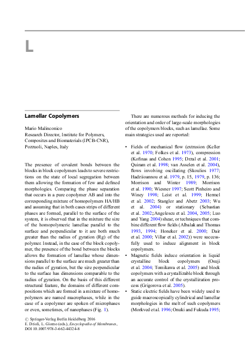
 Dick Broer