WO2021075895A1 - Organic light-emitting device - Google Patents
Organic light-emitting device Download PDFInfo
- Publication number
- WO2021075895A1 WO2021075895A1 PCT/KR2020/014140 KR2020014140W WO2021075895A1 WO 2021075895 A1 WO2021075895 A1 WO 2021075895A1 KR 2020014140 W KR2020014140 W KR 2020014140W WO 2021075895 A1 WO2021075895 A1 WO 2021075895A1
- Authority
- WO
- WIPO (PCT)
- Prior art keywords
- compound
- group
- formula
- substituted
- unsubstituted
- Prior art date
- Legal status (The legal status is an assumption and is not a legal conclusion. Google has not performed a legal analysis and makes no representation as to the accuracy of the status listed.)
- Ceased
Links
Images


Classifications
-
- C—CHEMISTRY; METALLURGY
- C07—ORGANIC CHEMISTRY
- C07D—HETEROCYCLIC COMPOUNDS
- C07D405/00—Heterocyclic compounds containing both one or more hetero rings having oxygen atoms as the only ring hetero atoms, and one or more rings having nitrogen as the only ring hetero atom
- C07D405/02—Heterocyclic compounds containing both one or more hetero rings having oxygen atoms as the only ring hetero atoms, and one or more rings having nitrogen as the only ring hetero atom containing two hetero rings
- C07D405/04—Heterocyclic compounds containing both one or more hetero rings having oxygen atoms as the only ring hetero atoms, and one or more rings having nitrogen as the only ring hetero atom containing two hetero rings directly linked by a ring-member-to-ring-member bond
-
- C—CHEMISTRY; METALLURGY
- C07—ORGANIC CHEMISTRY
- C07D—HETEROCYCLIC COMPOUNDS
- C07D403/00—Heterocyclic compounds containing two or more hetero rings, having nitrogen atoms as the only ring hetero atoms, not provided for by group C07D401/00
- C07D403/02—Heterocyclic compounds containing two or more hetero rings, having nitrogen atoms as the only ring hetero atoms, not provided for by group C07D401/00 containing two hetero rings
- C07D403/10—Heterocyclic compounds containing two or more hetero rings, having nitrogen atoms as the only ring hetero atoms, not provided for by group C07D401/00 containing two hetero rings linked by a carbon chain containing aromatic rings
-
- C—CHEMISTRY; METALLURGY
- C07—ORGANIC CHEMISTRY
- C07D—HETEROCYCLIC COMPOUNDS
- C07D409/00—Heterocyclic compounds containing two or more hetero rings, at least one ring having sulfur atoms as the only ring hetero atoms
- C07D409/02—Heterocyclic compounds containing two or more hetero rings, at least one ring having sulfur atoms as the only ring hetero atoms containing two hetero rings
- C07D409/04—Heterocyclic compounds containing two or more hetero rings, at least one ring having sulfur atoms as the only ring hetero atoms containing two hetero rings directly linked by a ring-member-to-ring-member bond
-
- C—CHEMISTRY; METALLURGY
- C07—ORGANIC CHEMISTRY
- C07D—HETEROCYCLIC COMPOUNDS
- C07D487/00—Heterocyclic compounds containing nitrogen atoms as the only ring hetero atoms in the condensed system, not provided for by groups C07D451/00 - C07D477/00
- C07D487/02—Heterocyclic compounds containing nitrogen atoms as the only ring hetero atoms in the condensed system, not provided for by groups C07D451/00 - C07D477/00 in which the condensed system contains two hetero rings
- C07D487/04—Ortho-condensed systems
-
- H—ELECTRICITY
- H10—SEMICONDUCTOR DEVICES; ELECTRIC SOLID-STATE DEVICES NOT OTHERWISE PROVIDED FOR
- H10K—ORGANIC ELECTRIC SOLID-STATE DEVICES
- H10K85/00—Organic materials used in the body or electrodes of devices covered by this subclass
- H10K85/60—Organic compounds having low molecular weight
- H10K85/615—Polycyclic condensed aromatic hydrocarbons, e.g. anthracene
- H10K85/622—Polycyclic condensed aromatic hydrocarbons, e.g. anthracene containing four rings, e.g. pyrene
-
- H—ELECTRICITY
- H10—SEMICONDUCTOR DEVICES; ELECTRIC SOLID-STATE DEVICES NOT OTHERWISE PROVIDED FOR
- H10K—ORGANIC ELECTRIC SOLID-STATE DEVICES
- H10K85/00—Organic materials used in the body or electrodes of devices covered by this subclass
- H10K85/60—Organic compounds having low molecular weight
- H10K85/649—Aromatic compounds comprising a hetero atom
- H10K85/654—Aromatic compounds comprising a hetero atom comprising only nitrogen as heteroatom
-
- H—ELECTRICITY
- H10—SEMICONDUCTOR DEVICES; ELECTRIC SOLID-STATE DEVICES NOT OTHERWISE PROVIDED FOR
- H10K—ORGANIC ELECTRIC SOLID-STATE DEVICES
- H10K85/00—Organic materials used in the body or electrodes of devices covered by this subclass
- H10K85/60—Organic compounds having low molecular weight
- H10K85/649—Aromatic compounds comprising a hetero atom
- H10K85/657—Polycyclic condensed heteroaromatic hydrocarbons
- H10K85/6572—Polycyclic condensed heteroaromatic hydrocarbons comprising only nitrogen in the heteroaromatic polycondensed ring system, e.g. phenanthroline or carbazole
-
- H—ELECTRICITY
- H10—SEMICONDUCTOR DEVICES; ELECTRIC SOLID-STATE DEVICES NOT OTHERWISE PROVIDED FOR
- H10K—ORGANIC ELECTRIC SOLID-STATE DEVICES
- H10K85/00—Organic materials used in the body or electrodes of devices covered by this subclass
- H10K85/60—Organic compounds having low molecular weight
- H10K85/649—Aromatic compounds comprising a hetero atom
- H10K85/657—Polycyclic condensed heteroaromatic hydrocarbons
- H10K85/6574—Polycyclic condensed heteroaromatic hydrocarbons comprising only oxygen in the heteroaromatic polycondensed ring system, e.g. cumarine dyes
-
- H—ELECTRICITY
- H10—SEMICONDUCTOR DEVICES; ELECTRIC SOLID-STATE DEVICES NOT OTHERWISE PROVIDED FOR
- H10K—ORGANIC ELECTRIC SOLID-STATE DEVICES
- H10K85/00—Organic materials used in the body or electrodes of devices covered by this subclass
- H10K85/60—Organic compounds having low molecular weight
- H10K85/649—Aromatic compounds comprising a hetero atom
- H10K85/657—Polycyclic condensed heteroaromatic hydrocarbons
- H10K85/6576—Polycyclic condensed heteroaromatic hydrocarbons comprising only sulfur in the heteroaromatic polycondensed ring system, e.g. benzothiophene
-
- C—CHEMISTRY; METALLURGY
- C07—ORGANIC CHEMISTRY
- C07B—GENERAL METHODS OF ORGANIC CHEMISTRY; APPARATUS THEREFOR
- C07B2200/00—Indexing scheme relating to specific properties of organic compounds
- C07B2200/05—Isotopically modified compounds, e.g. labelled
-
- H—ELECTRICITY
- H10—SEMICONDUCTOR DEVICES; ELECTRIC SOLID-STATE DEVICES NOT OTHERWISE PROVIDED FOR
- H10K—ORGANIC ELECTRIC SOLID-STATE DEVICES
- H10K2101/00—Properties of the organic materials covered by group H10K85/00
- H10K2101/10—Triplet emission
-
- H—ELECTRICITY
- H10—SEMICONDUCTOR DEVICES; ELECTRIC SOLID-STATE DEVICES NOT OTHERWISE PROVIDED FOR
- H10K—ORGANIC ELECTRIC SOLID-STATE DEVICES
- H10K2101/00—Properties of the organic materials covered by group H10K85/00
- H10K2101/90—Multiple hosts in the emissive layer
-
- H—ELECTRICITY
- H10—SEMICONDUCTOR DEVICES; ELECTRIC SOLID-STATE DEVICES NOT OTHERWISE PROVIDED FOR
- H10K—ORGANIC ELECTRIC SOLID-STATE DEVICES
- H10K50/00—Organic light-emitting devices
- H10K50/10—OLEDs or polymer light-emitting diodes [PLED]
- H10K50/11—OLEDs or polymer light-emitting diodes [PLED] characterised by the electroluminescent [EL] layers
-
- H—ELECTRICITY
- H10—SEMICONDUCTOR DEVICES; ELECTRIC SOLID-STATE DEVICES NOT OTHERWISE PROVIDED FOR
- H10K—ORGANIC ELECTRIC SOLID-STATE DEVICES
- H10K85/00—Organic materials used in the body or electrodes of devices covered by this subclass
- H10K85/30—Coordination compounds
- H10K85/341—Transition metal complexes, e.g. Ru(II)polypyridine complexes
- H10K85/342—Transition metal complexes, e.g. Ru(II)polypyridine complexes comprising iridium
Definitions
- the present invention relates to an organic light emitting device.
- the organic light emission phenomenon refers to a phenomenon in which electrical energy is converted into light energy by using an organic material.
- An organic light-emitting device using the organic light-emitting phenomenon has a wide viewing angle, excellent contrast, and fast response time, and has excellent luminance, driving voltage, and response speed characteristics, and thus many studies are being conducted.
- An organic light-emitting device generally has a structure including an anode and a cathode, and an organic material layer between the anode and the cathode.
- the organic material layer is often made of a multi-layered structure made of different materials in order to increase the efficiency and stability of the organic light emitting device.For example, it may be formed of a hole injection layer, a hole transport layer, a light emitting layer, an electron transport layer, an electron injection layer, and the like.
- holes are injected from the anode and electrons from the cathode are injected into the organic material layer, and excitons are formed when the injected holes and electrons meet. When it falls back to the ground, it glows.
- Patent Document 1 Korean Patent Publication No. 10-2000-0051826
- the present invention relates to an organic light-emitting device having improved driving voltage, efficiency, and lifetime.
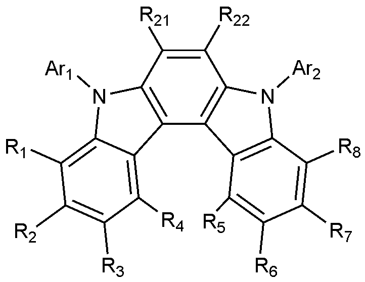
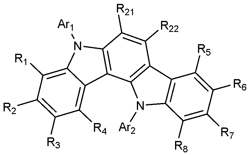
- the present invention includes an anode, a hole injection layer, a hole transport layer, a light emitting layer, and a cathode, wherein the light emitting layer is a compound represented by the following formula (1); And it provides an organic light emitting device comprising a compound represented by the following formula (2):
- A is a benzene ring fused with two adjacent pentagonal rings
- R 1 to R 8 are each independently hydrogen; heavy hydrogen; Substituted or unsubstituted C 1-60 alkyl; Substituted or unsubstituted C 6-60 aryl; Or substituted or unsubstituted C 2-60 heteroaryl containing any one or more heteroatoms selected from the group consisting of N, O and S,
- Ar 1 and Ar 2 are each independently a substituted or unsubstituted C 6-60 aryl; Or substituted or unsubstituted C 2-60 heteroaryl containing any one or more heteroatoms selected from the group consisting of N, O and S,
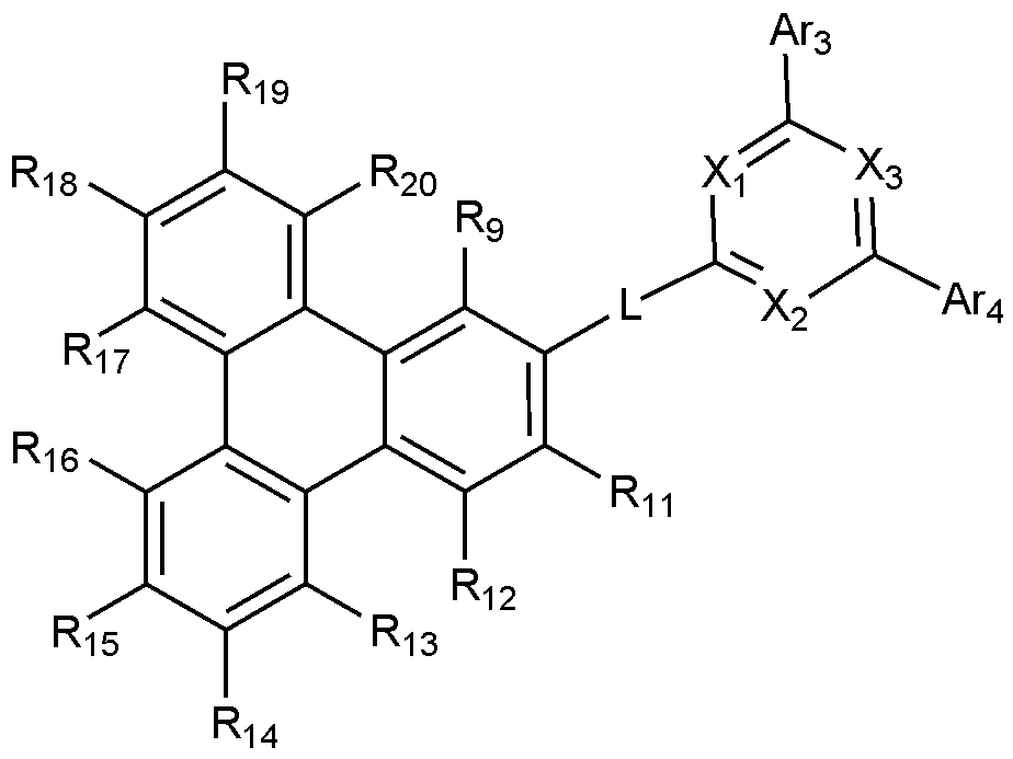
- X 1 to X 3 are each independently N or CH, at least one of which is N,
- L is a substituted or unsubstituted C 2-60 heteroarylene including any one or more heteroatoms selected from the group consisting of N, O, and S; Or C 6-60 arylene substituted with C 2-20 heteroaryl containing any one or more heteroatoms selected from the group consisting of N, O and S,
- Ar 3 and Ar 4 are each independently a substituted or unsubstituted C 6-60 aryl; Or substituted or unsubstituted C 2-60 heteroaryl containing any one or more heteroatoms selected from the group consisting of N, O and S,
- R 9 to R 12 is a bond with L, and the remaining R 9 to R 12 that are not bonded to L are each independently hydrogen; heavy hydrogen; Substituted or unsubstituted C 1-60 alkyl; Substituted or unsubstituted C 6-60 aryl; Or substituted or unsubstituted C 2-60 heteroaryl containing any one or more heteroatoms selected from the group consisting of N, O and S,
- R 13 to R 20 are each independently hydrogen; heavy hydrogen; Substituted or unsubstituted C 1-60 alkyl; Substituted or unsubstituted C 6-60 aryl; Or substituted or unsubstituted C 2-60 heteroaryl including any one or more heteroatoms selected from the group consisting of N, O and S.
- the organic light-emitting device may simultaneously include a compound having excellent hole transport characteristics and a compound having excellent electron transport characteristics in the emission layer, thereby securing excellent current efficiency and lifespan characteristics, and improving power efficiency.
- FIG. 1 shows an example of an organic light-emitting device comprising a substrate 1, an anode 2, a hole transport layer 3, a light-emitting layer 4, an electron transport layer 5, and a cathode 6.
- FIG. 2 is a substrate (1), an anode (2), a hole injection layer (7), a hole transport layer (3), a light emitting layer (4), an electron transport layer (5), an electron injection layer (8) and a cathode (6). It shows an example of an organic light-emitting device.
- substituted or unsubstituted refers to deuterium; Halogen group; Cyano group; Nitro group; Hydroxy group; Carbonyl group; Ester group; Imide group; Amino group; Phosphine oxide group; Alkoxy group; Aryloxy group; Alkyl thioxy group; Arylthioxy group; Alkyl sulfoxy group; Arylsulfoxy group; Silyl group; Boron group; Alkyl group; Cycloalkyl group; Alkenyl group; Aryl group; Aralkyl group; Aralkenyl group; Alkylaryl group; Alkylamine group; Aralkylamine group; Heteroarylamine group; Arylamine group; Arylphosphine group; Or it means substituted or unsubstituted with one or more substituents selected from the group consisting of heteroaryl containing one or more of N, O, and S atoms, or substituted or unsubstituted with two or more substituents selected from the group consisting of heteroary
- a substituent to which two or more substituents are connected may be a biphenyl group. That is, the biphenyl group may be an aryl group, or may be interpreted as a substituent to which two phenyl groups are connected.
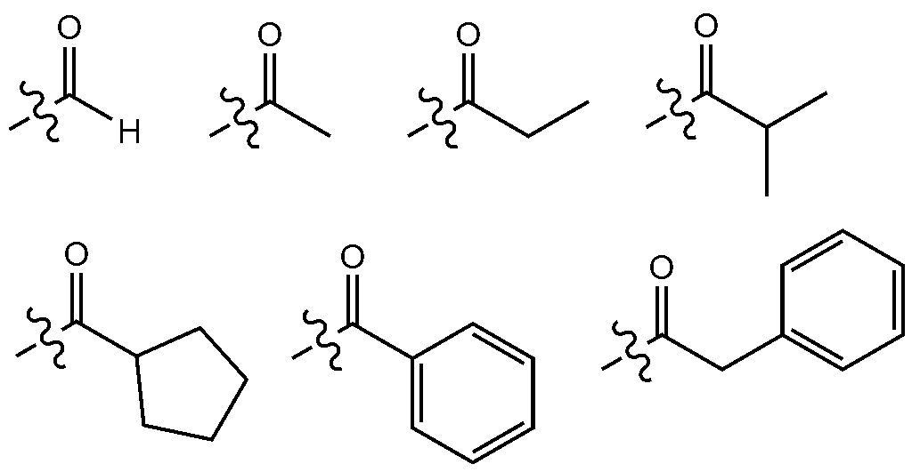
- the number of carbon atoms of the carbonyl group is not particularly limited, but is preferably 1 to 40 carbon atoms. Specifically, it may be a compound having the following structure, but is not limited thereto.
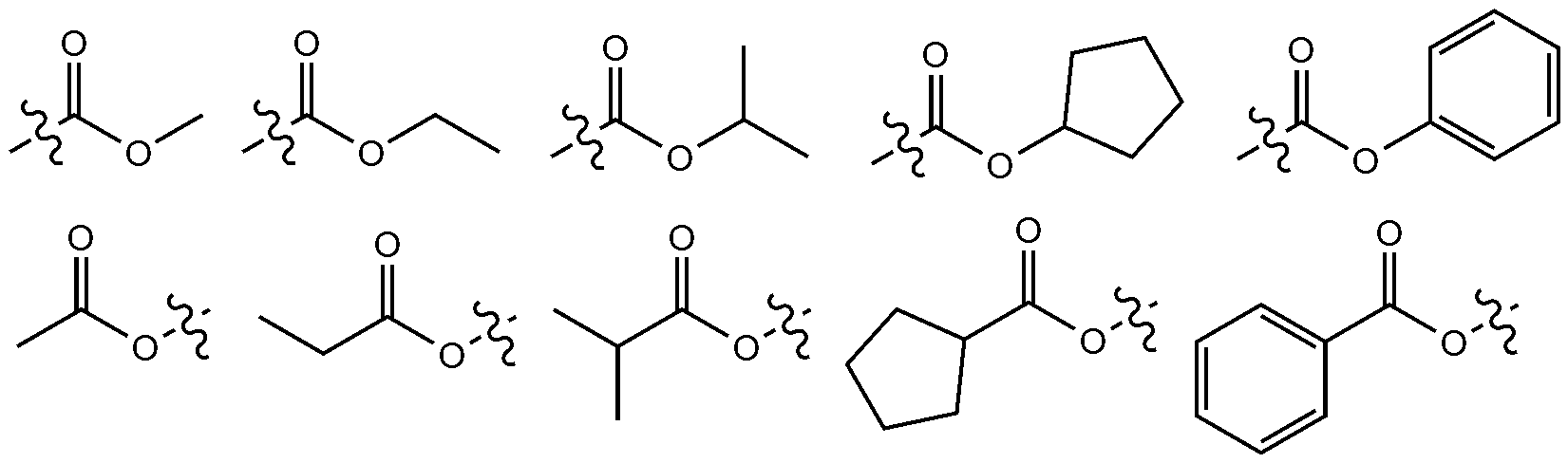
- the ester group may be substituted with a C1-C25 linear, branched or cyclic alkyl group or an aryl group having 6 to 25 carbon atoms in the oxygen of the ester group.
- it may be a compound of the following structural formula, but is not limited thereto.
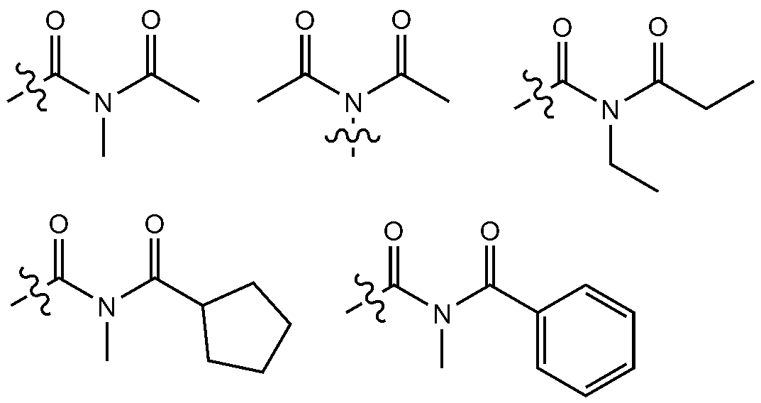
- the number of carbon atoms of the imide group is not particularly limited, but it is preferably 1 to 25 carbon atoms. Specifically, it may be a compound having the following structure, but is not limited thereto.
- the silyl group is specifically trimethylsilyl group, triethylsilyl group, t-butyldimethylsilyl group, vinyldimethylsilyl group, propyldimethylsilyl group, triphenylsilyl group, diphenylsilyl group, phenylsilyl group, etc. However, it is not limited thereto.
- the boron group specifically includes a trimethyl boron group, a triethyl boron group, a t-butyldimethyl boron group, a triphenyl boron group, and a phenyl boron group, but is not limited thereto.
- examples of the halogen group include fluorine, chlorine, bromine or iodine.
- the alkyl group may be linear or branched, and the number of carbon atoms is not particularly limited, but is preferably 1 to 40. According to an exemplary embodiment, the alkyl group has 1 to 20 carbon atoms. According to another exemplary embodiment, the alkyl group has 1 to 10 carbon atoms. According to another exemplary embodiment, the alkyl group has 1 to 6 carbon atoms.
- alkyl group examples include methyl, ethyl, propyl, n-propyl, isopropyl, butyl, n-butyl, isobutyl, tert-butyl, sec-butyl, 1-methyl-butyl, 1-ethyl-butyl, pentyl, n -Pentyl, isopentyl, neopentyl, tert-pentyl, hexyl, n-hexyl, 1-methylpentyl, 2-methylpentyl, 4-methyl-2-pentyl, 3,3-dimethylbutyl, 2-ethylbutyl, heptyl , n-heptyl, 1-methylhexyl, cyclopentylmethyl, cycloheptylmethyl, octyl, n-octyl, tert-octyl, 1-methylheptyl, 2-ethylhex
- the alkenyl group may be a linear or branched chain, and the number of carbon atoms is not particularly limited, but is preferably 2 to 40. According to an exemplary embodiment, the alkenyl group has 2 to 20 carbon atoms. According to another exemplary embodiment, the alkenyl group has 2 to 10 carbon atoms. According to another exemplary embodiment, the alkenyl group has 2 to 6 carbon atoms.
- Specific examples include vinyl, 1-propenyl, isopropenyl, 1-butenyl, 2-butenyl, 3-butenyl, 1-pentenyl, 2-pentenyl, 3-pentenyl, 3-methyl-1- Butenyl, 1,3-butadienyl, allyl, 1-phenylvinyl-1-yl, 2-phenylvinyl-1-yl, 2,2-diphenylvinyl-1-yl, 2-phenyl-2-( Naphthyl-1-yl)vinyl-1-yl, 2,2-bis(diphenyl-1-yl)vinyl-1-yl, stilbenyl group, styrenyl group, and the like, but are not limited thereto.
- the cycloalkyl group is not particularly limited, but preferably has 3 to 60 carbon atoms, and according to an exemplary embodiment, the cycloalkyl group has 3 to 30 carbon atoms. According to another exemplary embodiment, the cycloalkyl group has 3 to 20 carbon atoms. According to another exemplary embodiment, the cycloalkyl group has 3 to 6 carbon atoms.
- the aryl group is not particularly limited, but is preferably 6 to 60 carbon atoms, and may be a monocyclic aryl group or a polycyclic aryl group. According to an exemplary embodiment, the aryl group has 6 to 30 carbon atoms. According to an exemplary embodiment, the aryl group has 6 to 20 carbon atoms.
- the aryl group may be a monocyclic aryl group such as a phenyl group, a biphenyl group, or a terphenyl group, but is not limited thereto.
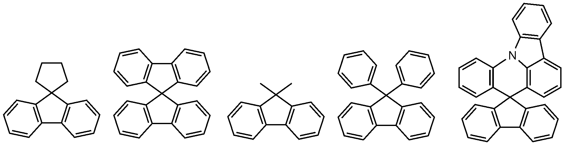
- the polycyclic aryl group may be a naphthyl group, an anthracenyl group, a phenanthrenyl group, a pyrenyl group, a perylenyl group, a chrysenyl group, a fluorenyl group, and the like, but is not limited thereto.
- the fluorenyl group may be substituted, and two substituents may be bonded to each other to form a spiro structure.
- the fluorenyl group is substituted, Can be, etc. However, it is not limited thereto.
- heteroaryl is a heteroaryl containing at least one of O, N, Si, and S as a heterogeneous element, and the number of carbon atoms is not particularly limited, but it is preferably 2 to 60 carbon atoms.
- heteroaryl include xanthene, thioxanthen, thiophene group, furan group, pyrrole group, imidazole group, thiazole group, oxazole group, oxadiazole group, triazole group, pyridyl group, bipyridyl group, Pyrimidyl group, triazine group, acridyl group, pyridazine group, pyrazinyl group, quinolinyl group, quinazoline group, quinoxalinyl group, phthalazinyl group, pyrido pyrimidinyl group, pyrido pyrazinyl group, pyrazino Pyrazinyl group, iso
- the aryl group among the aralkyl group, aralkenyl group, alkylaryl group, arylamine group, and arylsilyl group is the same as the example of the aryl group described above.
- the alkyl group among the aralkyl group, the alkylaryl group and the alkylamine group is the same as the example of the aforementioned alkyl group.
- the heteroaryl among the heteroarylamines may be described above for heteroaryl.
- the alkenyl group of the aralkenyl group is the same as the example of the alkenyl group described above.
- the description of the aryl group described above may be applied except that the arylene is a divalent group.
- the description of the above-described heteroaryl may be applied except that the heteroarylene is a divalent group.
- the hydrocarbon ring is not a monovalent group, and the description of the aryl group or cycloalkyl group described above may be applied except that the hydrocarbon ring is formed by bonding of two substituents.
- the heterocycle is not a monovalent group, and the description of the above-described heteroaryl may be applied except that the heterocycle is formed by bonding of two substituents.
- the organic light-emitting device includes an anode and a cathode.
- the cathode material a material having a large work function is preferable so that holes can be smoothly injected into the organic material layer.
- the cathode material include metals such as vanadium, chromium, copper, zinc, and gold, or alloys thereof; Metal oxides such as zinc oxide, indium oxide, indium tin oxide (ITO), and indium zinc oxide (IZO); Combinations of metals and oxides such as ZnO:Al or SnO 2 :Sb; Conductive compounds such as poly(3-methylthiophene), poly[3,4-(ethylene-1,2-dioxy)thiophene] (PEDOT), polypyrrole and polyaniline, and the like, but are not limited thereto.
- the cathode material is a material having a small work function to facilitate electron injection into the organic material layer.
- the negative electrode material include metals such as magnesium, calcium, sodium, potassium, titanium, indium, yttrium, lithium, gadolinium, aluminum, silver, tin, and lead, or alloys thereof; There are multilayered materials such as LiF/Al or LiO 2 /Al, but are not limited thereto.
- the organic light-emitting device may include a hole injection layer between the anode and the hole transport layer, if necessary.
- the hole injection layer is a layer that injects holes from the electrode, and has the ability to transport holes as a hole injection material, so that it has a hole injection effect at the anode, an excellent hole injection effect for the light emitting layer or the light emitting material, and is generated from the light emitting layer.
- a compound that prevents the movement of excitons to the electron injection layer or the electron injection material and has excellent ability to form a thin film is preferable.
- the HOMO (highest occupied molecular orbital) of the hole injection material is between the work function of the positive electrode material and the HOMO of the surrounding organic material layer.
- hole injection materials include metal porphyrin, oligothiophene, arylamine-based organic substances, hexanitrile hexaazatriphenylene-based organic substances, quinacridone-based organic substances, and perylene-based organic substances.
- the hole transport layer used in the present invention is a layer that receives holes from the anode or the hole injection layer formed on the anode and transports holes to the emission layer, and can be transported to the emission layer by transporting holes from the anode or the hole injection layer as a hole transport material.
- a material with high mobility for holes is suitable as a material. Specific examples include an arylamine-based organic material, a conductive polymer, and a block copolymer including a conjugated portion and a non-conjugated portion, but are not limited thereto.
- the light-emitting material included in the light-emitting layer is a material capable of emitting light in the visible light region by transporting and combining holes and electrons from the hole transport layer and the electron transport layer, respectively, and a material having good quantum efficiency for fluorescence or phosphorescence is preferable.
- the light emitting layer may include a host material and a dopant material.
- the compound represented by Formula 1 and the compound represented by Formula 2 are simultaneously used as host materials.
- the compound represented by Formula 1 may be represented by any one of Formulas 1-1 to 1-6 below.
- R 1 to R 8 , Ar 1 and Ar 2 are as defined in Formula 1, and R 21 to R 22 are each independently hydrogen or deuterium.
- Ar 1 and Ar 2 are each independently a substituted or unsubstituted C 6-20 aryl; Or substituted or unsubstituted C 2-20 heteroaryl including any one or more heteroatoms selected from the group consisting of N, O and S.
- Ar 1 and Ar 2 are each independently phenyl; Biphenylyl; Terphenylyl; Quarterphenylyl; 3',5'-diphenylbiphenylyl; Or dibenzofuranyl.
- Ar 1 and Ar 2 may each independently be any one selected from the group consisting of:
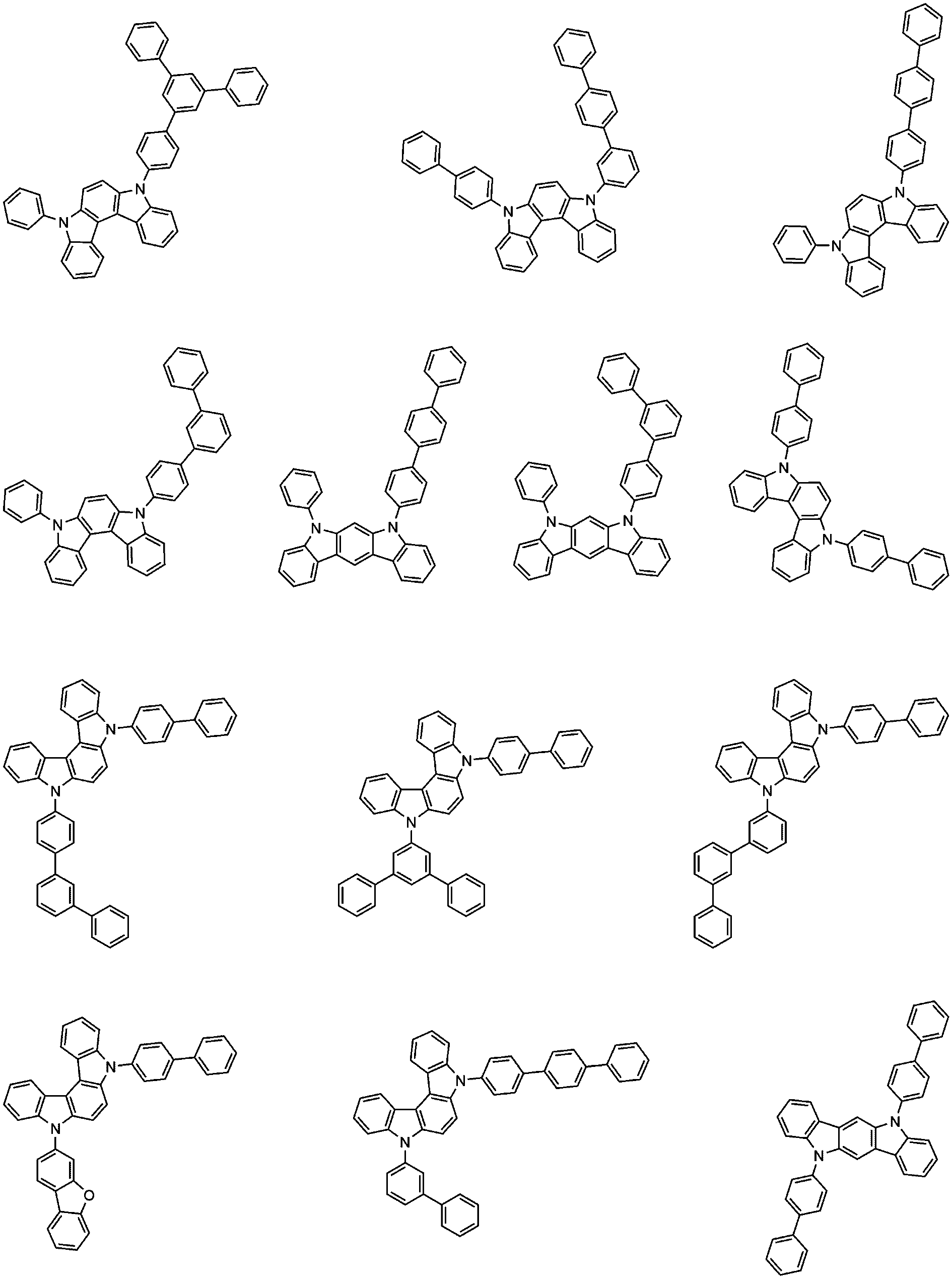
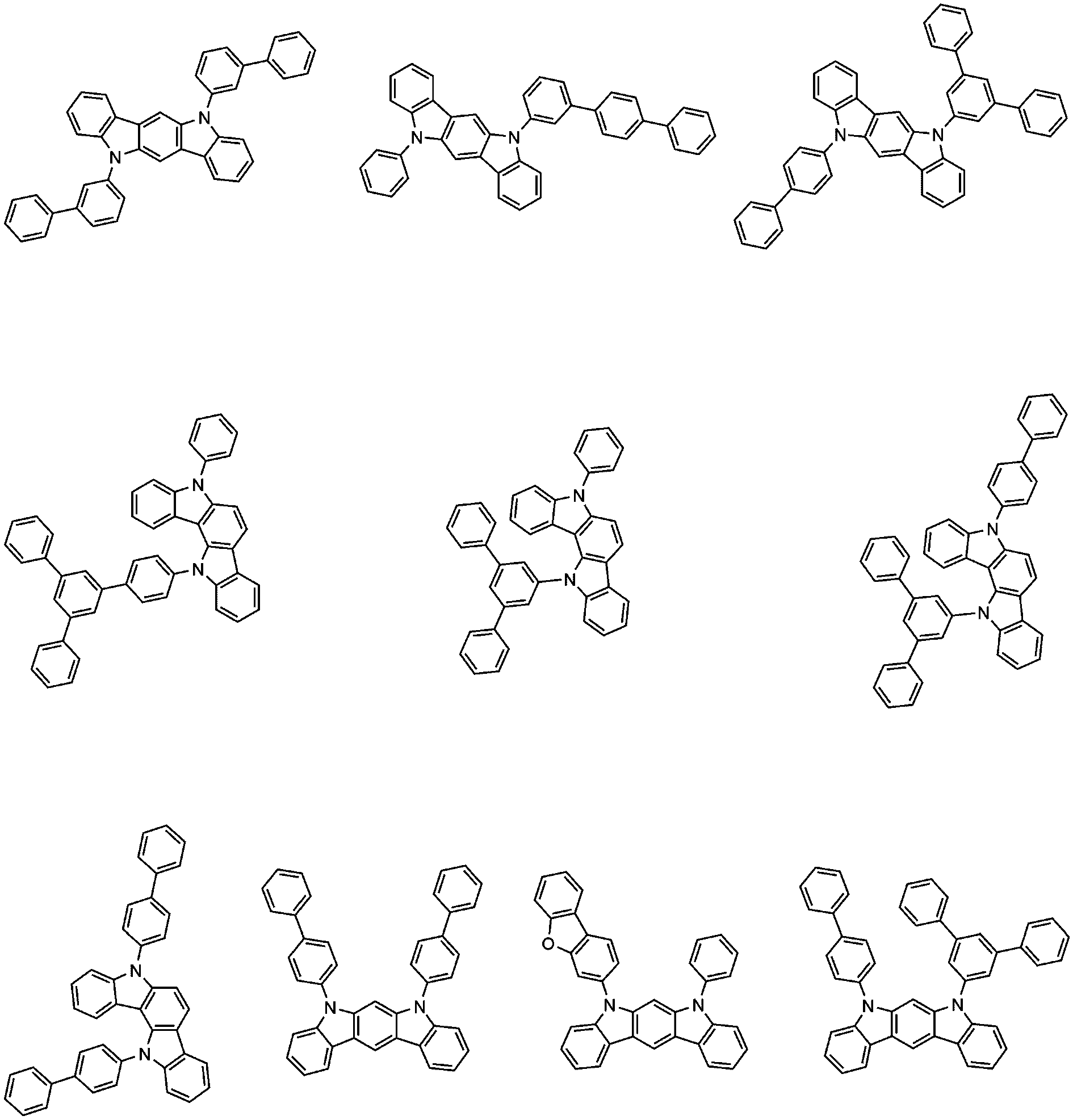
- the compound of Formula 1 may be any one selected from the group consisting of:
- any one of R 9 to R 12 is a bond with L.
- Formula 2 is represented by the following Formula 2-1 or Formula 2-2:
- X 1 to X 3 , L, Ar 3 , Ar 4 , R 9 to R 20 are as defined in Formula 2.
- the remaining R 9 to R 12 that are not bonded to L are each independently hydrogen or deuterium.
- all of the remaining R 9 to R 12 not bonded to L are hydrogen.
- R 13 to R 20 are each independently hydrogen or deuterium, and more preferably, all are hydrogen.
- Formula 2 is represented by Formula 2-2, wherein R 9 and R 11 to R 20 are both hydrogen.
- the L may be any one selected from the group consisting of the following.
- Ar 3 and Ar 4 are each independently phenyl; Phenyl substituted with 5 deuterium; Biphenyl; Naphthyl; Or terphenyl.
- Ar 3 and Ar 4 may each independently be any one selected from the group consisting of the following.
- all of X 1 to X 3 may be N.
- the compound of Formula 2 may be any one selected from the group consisting of:
- the lifespan and current efficiency of the organic light emitting device may be improved.
- the driving voltage is rather increased, so that the expected characteristics may not be expressed in power efficiency.
- the power efficiency characteristics are improved by lowering the driving voltage of the device by using the compound of Formula 1 as a P-type host together in the emission layer. Accordingly, the organic light emitting device of the present invention can simultaneously exhibit excellent current efficiency, power efficiency, and lifetime characteristics.
- the weight ratio of the compound represented by Formula 1 and the compound represented by Formula 2 may be from 5:5 to less than 8:2, or from 5:5 to 7:3.
- the compound represented by Formula 1 may be prepared in the same manner as in Scheme 1 below.
- Scheme 1 is an amine substitution reaction, preferably carried out in the presence of a palladium catalyst and a base, and the reactor for the amine substitution reaction may be changed as known in the art.
- the manufacturing method may be more specific in the manufacturing examples to be described later.
- the compound represented by Formula 2 may be prepared in the same manner as in Scheme 2 below.
- the reaction is a Suzuki coupling reaction, preferably carried out in the presence of a palladium catalyst and a base, and the reactor for the Suzuki coupling reaction can be changed as known in the art.
- the manufacturing method may be more specific in the manufacturing examples to be described later.
- examples of the dopant material include aromatic amine derivatives, strylamine compounds, boron complexes, fluoranthene compounds, and metal complexes.
- the aromatic amine derivative is a condensed aromatic ring derivative having a substituted or unsubstituted arylamino group, and includes pyrene, anthracene, chrysene, periflanthene and the like having an arylamino group
- the styrylamine compound is substituted or unsubstituted
- the styrylamine compound is substituted or unsubstituted
- a compound in which at least one arylvinyl group is substituted on the arylamine, one or two or more substituents selected from the group consisting of aryl group, silyl group, alkyl group, cycloalkyl group, and arylamino group are substituted or unsubstituted.
- styrylamine styryldiamine
- styryltriamine examples of the metal complex
- styryltetraamine examples of the metal complex include, but are not limited to, an iridium complex and a platinum complex.
- the organic light-emitting device according to the present invention may include an electron transport layer on the emission layer.
- the electron transport layer is a layer that receives electrons from the electron injection layer and transports electrons to the emission layer.
- an electron transport material a material capable of injecting electrons from the cathode and transferring them to the emission layer, and a material having high mobility for electrons is suitable. Do. Specific examples include Al complex of 8-hydroxyquinoline; Complexes containing Alq 3; Organic radical compounds; Hydroxyflavone-metal complexes and the like, but are not limited thereto.
- the electron transport layer can be used with any desired cathode material as used according to the prior art.
- suitable cathode materials are conventional materials that have a low work function and are followed by an aluminum layer or a silver layer. Specifically, they are cesium, barium, calcium, ytterbium, and samarium, and in each case an aluminum layer or a silver layer follows.
- the organic light emitting device may include an electron injection layer between an electron transport layer (or a light emitting layer) and a cathode, if necessary.
- the electron injection layer is a layer that injects electrons from the electrode, has the ability to transport electrons, has an electron injection effect from the cathode, an excellent electron injection effect for the light emitting layer or the light emitting material, and hole injection of excitons generated in the light emitting layer
- a compound that prevents migration to the layer and is excellent in thin film forming ability is preferable.
- Complex compounds and nitrogen-containing 5-membered ring derivatives but are not limited thereto.
- Examples of the metal complex compound include 8-hydroxyquinolinato lithium, bis(8-hydroxyquinolinato)zinc, bis(8-hydroxyquinolinato)copper, bis(8-hydroxyquinolinato)manganese, Tris(8-hydroxyquinolinato)aluminum, tris(2-methyl-8-hydroxyquinolinato)aluminum, tris(8-hydroxyquinolinato)gallium, bis(10-hydroxybenzo[h] Quinolinato)beryllium, bis(10-hydroxybenzo[h]quinolinato)zinc, bis(2-methyl-8-quinolinato)chlorogallium, bis(2-methyl-8-quinolinato)( o-cresolato)gallium, bis(2-methyl-8-quinolinato)(1-naphtholato)aluminum, bis(2-methyl-8-quinolinato)(2-naphtholato)gallium, etc. It is not limited to this.
- the organic light-emitting device according to the present invention may be a normal type organic light-emitting device in which an anode, one or more organic material layers, and a cathode are sequentially stacked on a substrate.
- the organic light-emitting device according to the present invention may be an inverted type organic light-emitting device in which a cathode, one or more organic material layers, and an anode are sequentially stacked on a substrate.
- FIGS. 1 and 2 the structure of an organic light-emitting device according to an embodiment of the present invention is illustrated in FIGS. 1 and 2.
- FIG. 1 shows an example of an organic light-emitting device comprising a substrate 1, an anode 2, a hole transport layer 3, a light-emitting layer 4, an electron transport layer 5, and a cathode 6.
- the compounds represented by Chemical Formulas 1 and 2 may be included in the emission layer.
- the organic light-emitting device according to the present invention can be manufactured by materials and methods known in the art, except for using the above-described materials.
- the organic light emitting device may be manufactured by sequentially laminating an anode, an organic material layer, and a cathode on a substrate.
- a PVD (physical vapor deposition) method such as sputtering or e-beam evaporation
- a metal or a conductive metal oxide or an alloy thereof is deposited on the substrate to form an anode.
- an organic material layer including a hole injection layer, a hole transport layer, a light emitting layer and an electron transport layer thereon it can be prepared by depositing a material that can be used as a cathode thereon.
- an organic light emitting device may be manufactured by sequentially depositing an organic material layer and an anode material from a cathode material on a substrate (WO 2003/012890).
- the manufacturing method is not limited thereto.
- an organic light emitting device may be manufactured by sequentially depositing an organic material layer and an anode material from a cathode material on a substrate (WO 2003/012890).
- the manufacturing method is not limited thereto.
- the organic light-emitting device according to the present invention may be a top emission type, a bottom emission type, or a double-sided emission type depending on the material used.
- the compound according to the present invention may be included in an organic solar cell or an organic transistor in addition to the organic light emitting device.
- step 2 of Synthesis Example 1-1 in the same manner as in the preparation method of compound 1-2, except that 5'-chloro-1,1':3',1''-terphenyl was used instead of compound a2.
- step 2 of Synthesis Example 1-1 compound D and 5'-chloro-1,1':3',1''-terphenyl was used instead of compound B and compound a2.
- step 2 of Synthesis Example 1-1 the preparation method of compound 1-2 and the method of preparing compound 1-2, except that the following 5-phenyl-5,11-dihydroindolo[3,2-b]carbazole was used instead of compound B
- step 2 of Synthesis Example 2-1 compound P-10 in the same manner as in the preparation method of compound P-2 in step 2 of compound 2-1, except that the following compound P-9 was used instead of compound P-1.
- step 3 of Synthesis Example 2-1 compound P-11 in the same manner as in the preparation method of compound P-3 in step 3 of compound 2-1, except that the following compound P-10 was used instead of compound P-2.
- was synthesized (41.8 g, yield 87%; MS: [M+H] + 280).
- step 4 of Synthesis Example 2-1 compound P-12 in the same manner as the preparation method of compound P-4 in step 4 of compound 2-1, except that the following compound P-11 was used instead of compound P-3.
- was synthesized (31.2 g, yield 85%; MS: [M+H] + 247).
- step 5 of Synthesis Example 2-1 compound P-13 in the same manner as the preparation method of compound P-5 in step 5 of compound 2-1, except that the following compound P-12 was used instead of compound P-4.
- was synthesized (MS: [M+H] + 434).
- step 6 of Synthesis Example 2-1 compound P-14 in the same manner as in the preparation method of compound P-6 in step 6 of compound 2-1, except that the following compound P-13 was used instead of compound P-5.
- was synthesized (MS: [M+H] + 434).
- step 7 of Synthesis Example 2-1 compound 2-17 in the same manner as in the preparation method of compound 2-1 in step 7 of compound 2-1, except that the following compound P-14 was used instead of compound P-6.
- was synthesized (MS: [M+H] + 626).
- step 2 of Synthesis Example 2-1 compound P-16 in the same manner as in the preparation method of compound P-2 in step 2 of compound 2-1, except that the following compound P-15 was used instead of compound P-1.
- step 3 of Synthesis Example 2-1 compound P-17 in the same manner as in the preparation method of compound P-3 in step 3 of compound 2-1, except that the following compound P-16 was used instead of compound P-2.
- was synthesized (42.2 g, yield 83%; MS: [M+H] + 280).
- step 4 of Synthesis Example 2-1 compound P-18 in the same manner as in the preparation method of compound P-4 in step 4 of compound 2-1, except that the following compound P-17 was used instead of compound P-3.
- was synthesized (34.1 g, yield 92%; MS: [M+H] + 247).
- compound P-18 (20 g, 81.1 mmol) and 2-brmotriphenylene (24.9 g, 81.1 mmol) were added to 400 mL of tetrahydrofuran, followed by stirring and refluxing. Thereafter, potassium carbonate (22.4 g, 162.3 mmol) was dissolved in 100 mL of water, and after sufficiently stirring, tetrakistriphenyl-phosphinopalladium (0.9 g, 0.8 mmol) was added. After reacting for 5 hours, the mixture was allowed to cool to room temperature, the organic layer and the water layer were separated, and the organic layer was distilled.
- step 6 of Synthesis Example 2-1 compound P-20 in the same manner as in the preparation method of compound P-6 in step 6 of compound 2-1, except that the following compound P-19 was used instead of compound P-5.
- was synthesized (MS: [M+H] + 521).
- step 2 of Synthesis Example 2-1 compound P-22 in the same manner as in the preparation method of compound P-2 in step 2 of compound 2-1, except that the following compound P-21 was used instead of compound P-1.
- was synthesized (72.9 g, yield 97%; MS: [M+H] + 300).
- step 3 of Synthesis Example 2-1 compound P-23 in the same manner as in the preparation method of compound P-3 in step 3 of compound 2-1, except that the following compound P-22 was used instead of compound P-2.
- step 4 of Synthesis Example 2-1 compound P-24 in the same manner as in the preparation method of compound P-4 in step 4 of compound 2-1, except that the following compound P-23 was used instead of compound P-3.
- was synthesized (44.9 g, yield 90%; MS: [M+H] + 247).
- step 5 of Synthesis Example 2-5 compound P-25 in the same manner as in the preparation method of compound P-19 in step 5 of compound 2-5, except that the following compound P-24 was used instead of compound P-18.
- was synthesized (MS: [M+H] + 429).
- step 6 of Synthesis Example 2-1 compound P-26 in the same manner as in the preparation method of compound P-6 in step 6 of compound 2-1, except that the following compound P-25 was used instead of compound P-5.
- was synthesized (MS: [M+H] + 521).
- step 7 of Synthesis Example 2-5 compound 2-23 in the same manner as in the preparation method of compound 2-20 in step 7 of compound 2-5, except that the following compound P-26 was used instead of compound P-20.
- was synthesized (MS: [M+H] + 631).
- step 2 of Synthesis Example 2-1 compound P-29 in the same manner as in the preparation method of compound P-2 in step 2 of compound 2-1, except that the following compound P-28 was used instead of compound P-1.
- step 3 of Synthesis Example 2-1 compound P-30 in the same manner as in the preparation method of compound P-3 in step 3 of compound 2-1, except that the following compound P-29 was used instead of compound P-2.
- step 4 of Synthesis Example 2-1 compound P-31 was used in the same manner as in the method of preparing compound P-4 in step 4 of compound 2-1, except that the following compound P-30 was used instead of compound P-3.
- was synthesized (40.1 g, yield 95%; MS: [M+H] + 247).
- step 5 of Synthesis Example 2-1 compound P-32 in the same manner as in the preparation method of compound P-5 in step 5 of compound 2-1, except that the following compound P-31 was used instead of compound P-4.
- was synthesized (MS: [M+H] + 434).
- step 6 of Synthesis Example 2-1 compound P-33 in the same manner as in the preparation method of compound P-6 in step 6 of compound 2-1, except that the following compound P-32 was used instead of compound P-5.
- was synthesized (MS: [M+H] + 434).
- step 7 of Synthesis Example 2-1 compound 2-27 in the same manner as in the preparation method of compound 2-1 in step 7 of compound 2-1, except that the following compound P-33 was used instead of compound P-6.
- was synthesized (MS: [M+H] + 626).
- step 4 of Synthesis Example 2-1 compound P-38 in the same manner as in the preparation method of compound P-4 in step 4 of compound 2-1, except that the following compound P-37 was used instead of compound P-3.
- was synthesized (20.4 g, yield 75%; MS: [M+H] + 263).
- step 5 of Synthesis Example 2-5 compound P-39 in the same manner as in the preparation method of compound P-19 in step 5 of compound 2-5, except that the following compound P-38 was used instead of compound P-18.
- was synthesized (MS: [M+H] + 445).
- step 6 of Synthesis Example 2-1 compound P-40 in the same manner as in the preparation method of compound P-6 in step 6 of compound 2-1, except that the following compound P-39 was used instead of compound P-5.
- was synthesized (MS: [M+H] + 537).
- step 7 of Synthesis Example 2-5 compound 2-37 in the same manner as in the preparation method of compound 2-20 in step 7 of compound 2-5, except that the following compound P-40 was used instead of compound P-20.
- was synthesized (MS: [M+H] + 647).
- a glass substrate coated with a thin film of 1300 ⁇ of ITO (indium tin oxide) was placed in distilled water dissolved in a detergent and washed with ultrasonic waves.
- ITO indium tin oxide
- a product made by Fischer Co. was used as a detergent, and distilled water secondarily filtered with a filter manufactured by Millipore Co. was used as distilled water.
- ultrasonic washing was performed for 10 minutes by repeating twice with distilled water.
- the following HTL1 compound and the following P-dopant were vacuum-deposited at a weight ratio of 100:2 to a thickness of 100 ⁇ to form a hole injection layer.
- the following HTL1 compound was vacuum-deposited to a thickness of 1100 ⁇
- the HTL2 compound was sequentially vacuum deposited to a thickness of 300 ⁇
- the following EBL compound was vacuum-deposited to a thickness of 300 ⁇ to form a hole transport layer.
- compound 1-1, compound 2-1, and the following GD compound prepared above were vacuum-deposited at a weight ratio of 50:50:6 to a thickness of 350 ⁇ to form a light emitting layer.
- the following HBL compound was vacuum-deposited on the emission layer to a thickness of 30 ⁇
- the following ETL compound was vacuum-deposited to a thickness of 180 ⁇
- the LiQ compound was sequentially vacuum-deposited to a thickness of 90 ⁇ to form an electron transport layer.
- LiF and Yb were vacuum-deposited to a thickness of 20 ⁇ at 1:1 to form an electron injection layer thereon.
- aluminum By depositing aluminum to a thickness of 1000 ⁇ on the electron injection layer, an organic light emitting device was manufactured. Thereafter, the final organic light emitting device was manufactured through an aging process in which it was left in an oven at 110° C. for 40 minutes.
- a cluster type vacuum evaporator (Selcos) was used for deposition.
- the deposition rate of the organic material was maintained at 0.4 to 0.7 ⁇ /sec
- the aluminum of the cathode maintained the deposition rate of 2 ⁇ /sec
- the vacuum degree during deposition was maintained at 1.0 X 10 -7 torr.
- Example 1 an organic light emitting device was manufactured in the same manner as in Example 1, except that the compounds shown in Table 1 below were used instead of compounds 1-1 and 2-1 as host compounds of the emission layer.
- P-Host and N-Host are as follows.
- LT97 refers to the time it takes for the luminance to decrease from the initial luminance (1600 nit) to 97% at a current density of 20 mA/cm 2.
- Photo Research's PR-670 Power source: 2635B (Keithley's) was used as the IVL measuring instrument, and McScience's M6000 was used for life measurement.
- the organic light-emitting device including the compound of Formula 1 and the compound of Formula 2 of the present invention in the emission layer has a lower driving voltage than the organic light-emitting device of Comparative Example, and exhibits high efficiency and long life characteristics. .
- substrate 2 anode
- hole transport layer 4 light emitting layer
Landscapes
- Chemical & Material Sciences (AREA)
- Organic Chemistry (AREA)
- Physics & Mathematics (AREA)
- Spectroscopy & Molecular Physics (AREA)
- Engineering & Computer Science (AREA)
- Materials Engineering (AREA)
- Electroluminescent Light Sources (AREA)
Abstract
Description
관련 출원(들)과의 상호 인용Cross-reference with related application(s)
본 출원은 2019년 10월 18일자 한국 특허 출원 제10-2019-0129952호 및 2020년 10월 16일자 한국 특허 출원 제10-2020-0133931호에 기초한 우선권의 이익을 주장하며, 해당 한국 특허 출원의 문헌에 개시된 모든 내용은 본 명세서의 일부로서 포함된다.This application claims the benefit of priority based on Korean Patent Application No. 10-2019-0129952 filed October 18, 2019 and Korean Patent Application No. 10-2020-0133931 filed October 16, 2020. All contents disclosed in the literature are included as part of this specification.
본 발명은 유기 발광 소자에 관한 것이다. The present invention relates to an organic light emitting device.
일반적으로 유기 발광 현상이란 유기 물질을 이용하여 전기에너지를 빛에너지로 전환시켜주는 현상을 말한다. 유기 발광 현상을 이용하는 유기 발광 소자는 넓은 시야각, 우수한 콘트라스트, 빠른 응답 시간을 가지며, 휘도, 구동 전압 및 응답 속도 특성이 우수하여 많은 연구가 진행되고 있다. In general, the organic light emission phenomenon refers to a phenomenon in which electrical energy is converted into light energy by using an organic material. An organic light-emitting device using the organic light-emitting phenomenon has a wide viewing angle, excellent contrast, and fast response time, and has excellent luminance, driving voltage, and response speed characteristics, and thus many studies are being conducted.
유기 발광 소자는 일반적으로 양극과 음극 및 상기 양극과 음극 사이에 유기물층을 포함하는 구조를 가진다. 상기 유기물층은 유기 발광 소자의 효율과 안정성을 높이기 위하여 각기 다른 물질로 구성된 다층의 구조로 이루어진 경우가 많으며, 예컨대 정공주입층, 정공수송층, 발광층, 전자수송층, 전자주입층 등으로 이루어질 수 있다. 이러한 유기 발광 소자의 구조에서 두 전극 사이에 전압을 걸어주게 되면 양극에서는 정공이, 음극에서는 전자가 유기물층에 주입되게 되고, 주입된 정공과 전자가 만났을 때 엑시톤(exciton)이 형성되며, 이 엑시톤이 다시 바닥상태로 떨어질 때 빛이 나게 된다. An organic light-emitting device generally has a structure including an anode and a cathode, and an organic material layer between the anode and the cathode. The organic material layer is often made of a multi-layered structure made of different materials in order to increase the efficiency and stability of the organic light emitting device.For example, it may be formed of a hole injection layer, a hole transport layer, a light emitting layer, an electron transport layer, an electron injection layer, and the like. In the structure of such an organic light emitting device, when a voltage is applied between the two electrodes, holes are injected from the anode and electrons from the cathode are injected into the organic material layer, and excitons are formed when the injected holes and electrons meet. When it falls back to the ground, it glows.
상기와 같은 유기 발광 소자에 사용되는 유기물에 대하여 새로운 재료의 개발이 지속적으로 요구되고 있다.Development of new materials for organic materials used in organic light emitting devices as described above is continuously required.
[선행기술문헌][Prior technical literature]
특허문헌 1: 한국특허 공개번호 제10-2000-0051826호Patent Document 1: Korean Patent Publication No. 10-2000-0051826
본 발명은 구동 전압, 효율 및 수명이 개선된 유기 발광 소자에 관한 것이다.The present invention relates to an organic light-emitting device having improved driving voltage, efficiency, and lifetime.
본 발명은, 양극, 정공주입층, 정공수송층, 발광층, 및 음극을 포함하고, 상기 발광층은 하기 화학식 1로 표시되는 화합물; 및 하기 화학식 2로 표시되는 화합물을 포함하는, 유기 발광 소자를 제공한다:The present invention includes an anode, a hole injection layer, a hole transport layer, a light emitting layer, and a cathode, wherein the light emitting layer is a compound represented by the following formula (1); And it provides an organic light emitting device comprising a compound represented by the following formula (2):
[화학식 1][Formula 1]

상기 화학식 1에서,In Formula 1,
A는 인접한 두 개의 오각 고리와 융합된 벤젠고리이고,A is a benzene ring fused with two adjacent pentagonal rings,
R 1 내지 R 8은 각각 독립적으로, 수소; 중수소; 치환 또는 비치환된 C 1-60 알킬; 치환 또는 비치환된 C 6-60 아릴; 또는 치환 또는 비치환된 N, O 및 S로 구성되는 군으로부터 선택되는 어느 하나 이상의 헤테로원자를 포함하는 C 2-60 헤테로아릴이고,R 1 to R 8 are each independently hydrogen; heavy hydrogen; Substituted or unsubstituted C 1-60 alkyl; Substituted or unsubstituted C 6-60 aryl; Or substituted or unsubstituted C 2-60 heteroaryl containing any one or more heteroatoms selected from the group consisting of N, O and S,
Ar 1 및 Ar 2는 각각 독립적으로, 치환 또는 비치환된 C 6-60 아릴; 또는 치환 또는 비치환된 N, O 및 S로 구성되는 군으로부터 선택되는 어느 하나 이상의 헤테로원자를 포함하는 C 2-60 헤테로아릴이고,Ar 1 and Ar 2 are each independently a substituted or unsubstituted C 6-60 aryl; Or substituted or unsubstituted C 2-60 heteroaryl containing any one or more heteroatoms selected from the group consisting of N, O and S,
[화학식 2][Formula 2]
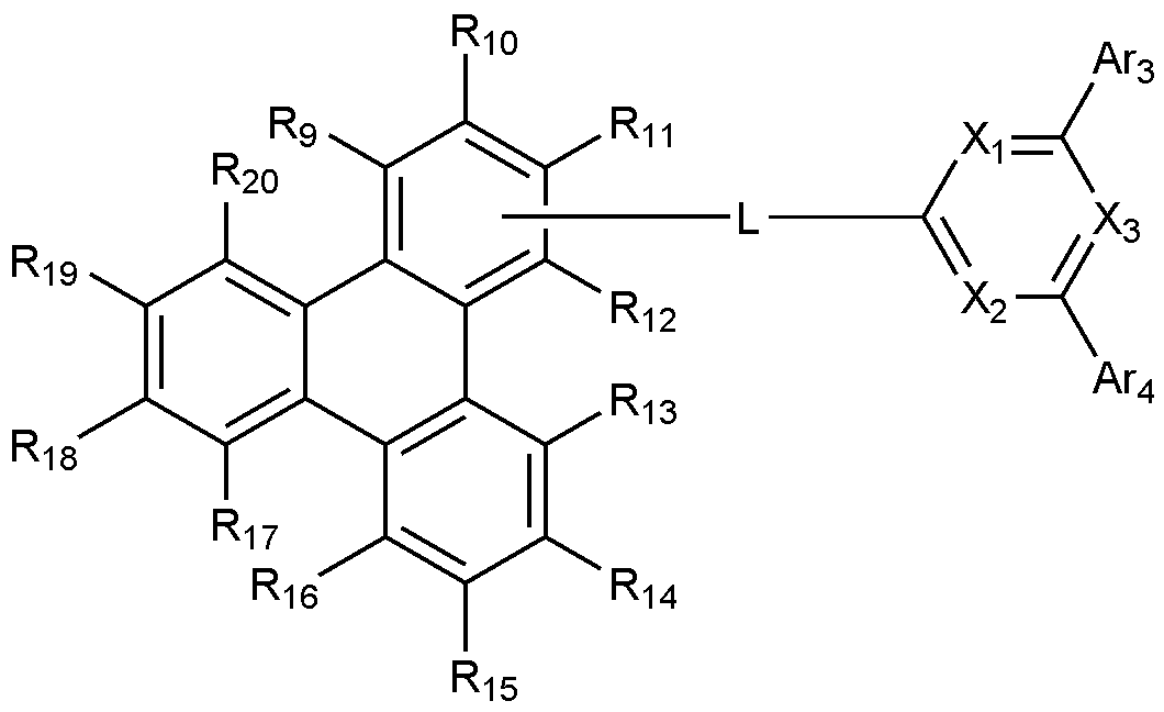
상기 화학식 2에서,In Chemical Formula 2,
X 1 내지 X 3는 각각 독립적으로 N 또는 CH이며, 이 중 적어도 하나는 N이고,X 1 to X 3 are each independently N or CH, at least one of which is N,
L은 치환 또는 비치환된 N, O 및 S로 구성되는 군으로부터 선택되는 어느 하나 이상의 헤테로원자를 포함하는 C 2-60 헤테로아릴렌; 또는 N, O 및 S로 구성되는 군으로부터 선택되는 어느 하나 이상의 헤테로원자를 포함하는 C 2-20 헤테로아릴로 치환된 C 6-60 아릴렌이고, L is a substituted or unsubstituted C 2-60 heteroarylene including any one or more heteroatoms selected from the group consisting of N, O, and S; Or C 6-60 arylene substituted with C 2-20 heteroaryl containing any one or more heteroatoms selected from the group consisting of N, O and S,
Ar 3 및 Ar 4는 각각 독립적으로, 치환 또는 비치환된 C 6-60 아릴; 또는 치환 또는 비치환된 N, O 및 S로 구성되는 군으로부터 선택되는 어느 하나 이상의 헤테로원자를 포함하는 C 2-60 헤테로아릴이고,Ar 3 and Ar 4 are each independently a substituted or unsubstituted C 6-60 aryl; Or substituted or unsubstituted C 2-60 heteroaryl containing any one or more heteroatoms selected from the group consisting of N, O and S,
R 9 내지 R 12 중 어느 하나는 L과의 결합이고, L과의 결합이 아닌 나머지 R 9 내지 R 12는 각각 독립적으로, 수소; 중수소; 치환 또는 비치환된 C 1-60 알킬; 치환 또는 비치환된 C 6-60 아릴; 또는 치환 또는 비치환된 N, O 및 S로 구성되는 군으로부터 선택되는 어느 하나 이상의 헤테로원자를 포함하는 C 2-60 헤테로아릴이고,Any one of R 9 to R 12 is a bond with L, and the remaining R 9 to R 12 that are not bonded to L are each independently hydrogen; heavy hydrogen; Substituted or unsubstituted C 1-60 alkyl; Substituted or unsubstituted C 6-60 aryl; Or substituted or unsubstituted C 2-60 heteroaryl containing any one or more heteroatoms selected from the group consisting of N, O and S,
R 13 내지 R 20은 각각 독립적으로, 수소; 중수소; 치환 또는 비치환된 C 1-60 알킬; 치환 또는 비치환된 C 6-60 아릴; 또는 치환 또는 비치환된 N, O 및 S로 구성되는 군으로부터 선택되는 어느 하나 이상의 헤테로원자를 포함하는 C 2-60 헤테로아릴이다.R 13 to R 20 are each independently hydrogen; heavy hydrogen; Substituted or unsubstituted C 1-60 alkyl; Substituted or unsubstituted C 6-60 aryl; Or substituted or unsubstituted C 2-60 heteroaryl including any one or more heteroatoms selected from the group consisting of N, O and S.
본 발명에 따른 유기 발광 소자는 발광층에 정공 전달 특성이 우수한 화합물과 전자 전달 특성이 우수한 화합물을 동시에 포함하여, 우수한 전류 효율과 수명 특성을 확보하는 동시에 전력 효율을 향상시킬 수 있다. The organic light-emitting device according to the present invention may simultaneously include a compound having excellent hole transport characteristics and a compound having excellent electron transport characteristics in the emission layer, thereby securing excellent current efficiency and lifespan characteristics, and improving power efficiency.
도 1은 기판(1), 양극(2), 정공수송층(3), 발광층(4), 전자수송층(5), 및 음극(6)으로 이루어진 유기 발광 소자의 예를 도시한 것이다. 1 shows an example of an organic light-emitting device comprising a
도 2는 기판 (1), 양극(2), 정공주입층(7), 정공수송층(3), 발광층(4), 전자수송층(5), 전자주입층(8) 및 음극(6)로 이루어진 유기 발광 소자의 예를 도시한 것이다. 2 is a substrate (1), an anode (2), a hole injection layer (7), a hole transport layer (3), a light emitting layer (4), an electron transport layer (5), an electron injection layer (8) and a cathode (6). It shows an example of an organic light-emitting device.
이하, 본 발명의 이해를 돕기 위하여 보다 상세히 설명한다.Hereinafter, it will be described in more detail to aid the understanding of the present invention.
(용어의 정의)(Definition of Terms)
본 명세서에서,
![]()
![]()
![]()
![]()
본 명세서에서 "치환 또는 비치환된" 이라는 용어는 중수소; 할로겐기; 시아노기; 니트로기; 히드록시기; 카보닐기; 에스테르기; 이미드기; 아미노기; 포스핀옥사이드기; 알콕시기; 아릴옥시기; 알킬티옥시기; 아릴티옥시기; 알킬술폭시기; 아릴술폭시기; 실릴기; 붕소기; 알킬기; 사이클로알킬기; 알케닐기; 아릴기; 아르알킬기; 아르알케닐기; 알킬아릴기; 알킬아민기; 아랄킬아민기; 헤테로아릴아민기; 아릴아민기; 아릴포스핀기; 또는 N, O 및 S 원자 중 1개 이상을 포함하는 헤테로아릴로 이루어진 군에서 선택된 1개 이상의 치환기로 치환 또는 비치환되거나, 상기 예시된 치환기 중 2 이상의 치환기가 연결된 치환 또는 비치환된 것을 의미한다. 예컨대, "2 이상의 치환기가 연결된 치환기"는 비페닐기일 수 있다. 즉, 비페닐이기는 아릴기일 수도 있고, 2개의 페닐기가 연결된 치환기로 해석될 수도 있다.In the present specification, the term "substituted or unsubstituted" refers to deuterium; Halogen group; Cyano group; Nitro group; Hydroxy group; Carbonyl group; Ester group; Imide group; Amino group; Phosphine oxide group; Alkoxy group; Aryloxy group; Alkyl thioxy group; Arylthioxy group; Alkyl sulfoxy group; Arylsulfoxy group; Silyl group; Boron group; Alkyl group; Cycloalkyl group; Alkenyl group; Aryl group; Aralkyl group; Aralkenyl group; Alkylaryl group; Alkylamine group; Aralkylamine group; Heteroarylamine group; Arylamine group; Arylphosphine group; Or it means substituted or unsubstituted with one or more substituents selected from the group consisting of heteroaryl containing one or more of N, O, and S atoms, or substituted or unsubstituted with two or more substituents connected among the above exemplified substituents. . For example, "a substituent to which two or more substituents are connected" may be a biphenyl group. That is, the biphenyl group may be an aryl group, or may be interpreted as a substituent to which two phenyl groups are connected.
본 명세서에서 카보닐기의 탄소수는 특별히 한정되지 않으나, 탄소수 1 내지 40인 것이 바람직하다. 구체적으로 하기와 같은 구조의 화합물이 될 수 있으나, 이에 한정되는 것은 아니다.In the present specification, the number of carbon atoms of the carbonyl group is not particularly limited, but is preferably 1 to 40 carbon atoms. Specifically, it may be a compound having the following structure, but is not limited thereto.
본 명세서에 있어서, 에스테르기는 에스테르기의 산소가 탄소수 1 내지 25의 직쇄, 분지쇄 또는 고리쇄 알킬기 또는 탄소수 6 내지 25의 아릴기로 치환될 수 있다. 구체적으로, 하기 구조식의 화합물이 될 수 있으나, 이에 한정되는 것은 아니다.In the present specification, the ester group may be substituted with a C1-C25 linear, branched or cyclic alkyl group or an aryl group having 6 to 25 carbon atoms in the oxygen of the ester group. Specifically, it may be a compound of the following structural formula, but is not limited thereto.
본 명세서에 있어서, 이미드기의 탄소수는 특별히 한정되지 않으나, 탄소수 1 내지 25인 것이 바람직하다. 구체적으로 하기와 같은 구조의 화합물이 될 수 있으나, 이에 한정되는 것은 아니다.In the present specification, the number of carbon atoms of the imide group is not particularly limited, but it is preferably 1 to 25 carbon atoms. Specifically, it may be a compound having the following structure, but is not limited thereto.
본 명세서에 있어서, 실릴기는 구체적으로 트리메틸실릴기, 트리에틸실릴기, t-부틸디메틸실릴기, 비닐디메틸실릴기, 프로필디메틸실릴기, 트리페닐실릴기, 디페닐실릴기, 페닐실릴기 등이 있으나 이에 한정되지 않는다. In the present specification, the silyl group is specifically trimethylsilyl group, triethylsilyl group, t-butyldimethylsilyl group, vinyldimethylsilyl group, propyldimethylsilyl group, triphenylsilyl group, diphenylsilyl group, phenylsilyl group, etc. However, it is not limited thereto.
본 명세서에 있어서, 붕소기는 구체적으로 트리메틸붕소기, 트리에틸붕소기, t-부틸디메틸붕소기, 트리페닐붕소기, 페닐붕소기 등이 있으나 이에 한정되지 않는다.In the present specification, the boron group specifically includes a trimethyl boron group, a triethyl boron group, a t-butyldimethyl boron group, a triphenyl boron group, and a phenyl boron group, but is not limited thereto.
본 명세서에 있어서, 할로겐기의 예로는 불소, 염소, 브롬 또는 요오드가 있다.In the present specification, examples of the halogen group include fluorine, chlorine, bromine or iodine.
본 명세서에 있어서, 상기 알킬기는 직쇄 또는 분지쇄일 수 있고, 탄소수는 특별히 한정되지 않으나 1 내지 40인 것이 바람직하다. 일 실시상태에 따르면, 상기 알킬기의 탄소수는 1 내지 20이다. 또 하나의 실시상태에 따르면, 상기 알킬기의 탄소수는 1 내지 10이다. 또 하나의 실시상태에 따르면, 상기 알킬기의 탄소수는 1 내지 6이다. 알킬기의 구체적인 예로는 메틸, 에틸, 프로필, n-프로필, 이소프로필, 부틸, n-부틸, 이소부틸, tert-부틸, sec-부틸, 1-메틸-부틸, 1-에틸-부틸, 펜틸, n-펜틸, 이소펜틸, 네오펜틸, tert-펜틸, 헥실, n-헥실, 1-메틸펜틸, 2-메틸펜틸, 4-메틸-2-펜틸, 3,3-디메틸부틸, 2-에틸부틸, 헵틸, n-헵틸, 1-메틸헥실, 사이클로펜틸메틸, 사이클로헥틸메틸, 옥틸, n-옥틸, tert-옥틸, 1-메틸헵틸, 2-에틸헥실, 2-프로필펜틸, n-노닐, 2,2-디메틸헵틸, 1-에틸-프로필, 1,1-디메틸-프로필, 이소헥실, 2-메틸펜틸, 4-메틸헥실, 5-메틸헥실 등이 있으나, 이들에 한정되지 않는다.In the present specification, the alkyl group may be linear or branched, and the number of carbon atoms is not particularly limited, but is preferably 1 to 40. According to an exemplary embodiment, the alkyl group has 1 to 20 carbon atoms. According to another exemplary embodiment, the alkyl group has 1 to 10 carbon atoms. According to another exemplary embodiment, the alkyl group has 1 to 6 carbon atoms. Specific examples of the alkyl group include methyl, ethyl, propyl, n-propyl, isopropyl, butyl, n-butyl, isobutyl, tert-butyl, sec-butyl, 1-methyl-butyl, 1-ethyl-butyl, pentyl, n -Pentyl, isopentyl, neopentyl, tert-pentyl, hexyl, n-hexyl, 1-methylpentyl, 2-methylpentyl, 4-methyl-2-pentyl, 3,3-dimethylbutyl, 2-ethylbutyl, heptyl , n-heptyl, 1-methylhexyl, cyclopentylmethyl, cycloheptylmethyl, octyl, n-octyl, tert-octyl, 1-methylheptyl, 2-ethylhexyl, 2-propylpentyl, n-nonyl, 2,2 -Dimethylheptyl, 1-ethyl-propyl, 1,1-dimethyl-propyl, isohexyl, 2-methylpentyl, 4-methylhexyl, 5-methylhexyl, and the like, but are not limited thereto.
본 명세서에 있어서, 상기 알케닐기는 직쇄 또는 분지쇄일 수 있고, 탄소수는 특별히 한정되지 않으나, 2 내지 40인 것이 바람직하다. 일 실시상태에 따르면, 상기 알케닐기의 탄소수는 2 내지 20이다. 또 하나의 실시상태에 따르면, 상기 알케닐기의 탄소수는 2 내지 10이다. 또 하나의 실시상태에 따르면, 상기 알케닐기의 탄소수는 2 내지 6이다. 구체적인 예로는 비닐, 1-프로페닐, 이소프로페닐, 1-부테닐, 2-부테닐, 3-부테닐, 1-펜테닐, 2-펜테닐, 3-펜테닐, 3-메틸-1-부테닐, 1,3-부타디에닐, 알릴, 1-페닐비닐-1-일, 2-페닐비닐-1-일, 2,2-디페닐비닐-1-일, 2-페닐-2-(나프틸-1-일)비닐-1-일, 2,2-비스(디페닐-1-일)비닐-1-일, 스틸베닐기, 스티레닐기 등이 있으나 이들에 한정되지 않는다.In the present specification, the alkenyl group may be a linear or branched chain, and the number of carbon atoms is not particularly limited, but is preferably 2 to 40. According to an exemplary embodiment, the alkenyl group has 2 to 20 carbon atoms. According to another exemplary embodiment, the alkenyl group has 2 to 10 carbon atoms. According to another exemplary embodiment, the alkenyl group has 2 to 6 carbon atoms. Specific examples include vinyl, 1-propenyl, isopropenyl, 1-butenyl, 2-butenyl, 3-butenyl, 1-pentenyl, 2-pentenyl, 3-pentenyl, 3-methyl-1- Butenyl, 1,3-butadienyl, allyl, 1-phenylvinyl-1-yl, 2-phenylvinyl-1-yl, 2,2-diphenylvinyl-1-yl, 2-phenyl-2-( Naphthyl-1-yl)vinyl-1-yl, 2,2-bis(diphenyl-1-yl)vinyl-1-yl, stilbenyl group, styrenyl group, and the like, but are not limited thereto.
본 명세서에 있어서, 사이클로알킬기는 특별히 한정되지 않으나, 탄소수 3 내지 60인 것이 바람직하며, 일 실시상태에 따르면, 상기 사이클로알킬기의 탄소수는 3 내지 30이다. 또 하나의 실시상태에 따르면, 상기 사이클로알킬기의 탄소수는 3 내지 20이다. 또 하나의 실시상태에 따르면, 상기 사이클로알킬기의 탄소수는 3 내지 6이다. 구체적으로 사이클로프로필, 사이클로부틸, 사이클로펜틸, 3-메틸사이클로펜틸, 2,3-디메틸사이클로펜틸, 사이클로헥실, 3-메틸사이클로헥실, 4-메틸사이클로헥실, 2,3-디메틸사이클로헥실, 3,4,5-트리메틸사이클로헥실, 4-tert-부틸사이클로헥실, 사이클로헵틸, 사이클로옥틸 등이 있으나, 이에 한정되지 않는다.In the present specification, the cycloalkyl group is not particularly limited, but preferably has 3 to 60 carbon atoms, and according to an exemplary embodiment, the cycloalkyl group has 3 to 30 carbon atoms. According to another exemplary embodiment, the cycloalkyl group has 3 to 20 carbon atoms. According to another exemplary embodiment, the cycloalkyl group has 3 to 6 carbon atoms. Specifically, cyclopropyl, cyclobutyl, cyclopentyl, 3-methylcyclopentyl, 2,3-dimethylcyclopentyl, cyclohexyl, 3-methylcyclohexyl, 4-methylcyclohexyl, 2,3-dimethylcyclohexyl, 3, 4,5-trimethylcyclohexyl, 4-tert-butylcyclohexyl, cycloheptyl, cyclooctyl, and the like, but are not limited thereto.
본 명세서에 있어서, 아릴기는 특별히 한정되지 않으나 탄소수 6 내지 60인 것이 바람직하며, 단환식 아릴기 또는 다환식 아릴기일 수 있다. 일 실시상태에 따르면, 상기 아릴기의 탄소수는 6 내지 30이다. 일 실시상태에 따르면, 상기 아릴기의 탄소수는 6 내지 20이다. 상기 아릴기가 단환식 아릴기로는 페닐기, 비페닐이기, 터페닐기 등이 될 수 있으나, 이에 한정되는 것은 아니다. 상기 다환식 아릴기로는 나프틸기, 안트라세닐기, 페난쓰레닐기, 파이레닐기, 페릴레닐기, 크라이세닐기, 플루오레닐기 등이 될 수 있으나, 이에 한정되는 것은 아니다.In the present specification, the aryl group is not particularly limited, but is preferably 6 to 60 carbon atoms, and may be a monocyclic aryl group or a polycyclic aryl group. According to an exemplary embodiment, the aryl group has 6 to 30 carbon atoms. According to an exemplary embodiment, the aryl group has 6 to 20 carbon atoms. The aryl group may be a monocyclic aryl group such as a phenyl group, a biphenyl group, or a terphenyl group, but is not limited thereto. The polycyclic aryl group may be a naphthyl group, an anthracenyl group, a phenanthrenyl group, a pyrenyl group, a perylenyl group, a chrysenyl group, a fluorenyl group, and the like, but is not limited thereto.
본 명세서에 있어서, 플루오레닐기는 치환될 수 있고, 치환기 2개가 서로 결합하여 스피로 구조를 형성할 수 있다. 상기 플루오레닐기가 치환되는 경우,
본 명세서에 있어서, 헤테로아릴은 이종 원소로 O, N, Si 및 S 중 1개 이상을 포함하는 헤테로아릴로서, 탄소수는 특별히 한정되지 않으나, 탄소수 2 내지 60인 것이 바람직하다. 헤테로아릴의 예로는 잔텐(xanthene), 티오잔텐(thioxanthen), 티오펜기, 퓨란기, 피롤기, 이미다졸기, 티아졸기, 옥사졸기, 옥사디아졸기, 트리아졸기, 피리딜기, 비피리딜기, 피리미딜기, 트리아진기, 아크리딜기, 피리다진기, 피라지닐기, 퀴놀리닐기, 퀴나졸린기, 퀴녹살리닐기, 프탈라지닐기, 피리도 피리미디닐기, 피리도 피라지닐기, 피라지노 피라지닐기, 이소퀴놀린기, 인돌기, 카바졸기, 벤즈옥사졸기, 벤조이미다졸기, 벤조티아졸기, 벤조카바졸기, 벤조티오펜기, 디벤조티오펜기, 벤조퓨라닐기, 페난쓰롤린기(phenanthroline), 이소옥사졸릴기, 티아디아졸릴기, 페노티아지닐기 및 디벤조퓨라닐기 등이 있으나, 이들에만 한정되는 것은 아니다.In the present specification, heteroaryl is a heteroaryl containing at least one of O, N, Si, and S as a heterogeneous element, and the number of carbon atoms is not particularly limited, but it is preferably 2 to 60 carbon atoms. Examples of heteroaryl include xanthene, thioxanthen, thiophene group, furan group, pyrrole group, imidazole group, thiazole group, oxazole group, oxadiazole group, triazole group, pyridyl group, bipyridyl group, Pyrimidyl group, triazine group, acridyl group, pyridazine group, pyrazinyl group, quinolinyl group, quinazoline group, quinoxalinyl group, phthalazinyl group, pyrido pyrimidinyl group, pyrido pyrazinyl group, pyrazino Pyrazinyl group, isoquinoline group, indole group, carbazole group, benzoxazole group, benzoimidazole group, benzothiazole group, benzocarbazole group, benzothiophene group, dibenzothiophene group, benzofuranyl group, phenanthroline group ( phenanthroline), isoxazolyl group, thiadiazolyl group, phenothiazinyl group, and dibenzofuranyl group, but are not limited thereto.
본 명세서에 있어서, 아르알킬기, 아르알케닐기, 알킬아릴기, 아릴아민기, 아릴실릴기 중의 아릴기는 전술한 아릴기의 예시와 같다. 본 명세서에 있어서, 아르알킬기, 알킬아릴기, 알킬아민기 중 알킬기는 전술한 알킬기의 예시와 같다. 본 명세서에 있어서, 헤테로아릴아민 중 헤테로아릴은 전술한 헤테로아릴에 관한 설명이 적용될 수 있다. 본 명세서에 있어서, 아르알케닐기 중 알케닐기는 전술한 알케닐기의 예시와 같다. 본 명세서에 있어서, 아릴렌은 2가기인 것을 제외하고는 전술한 아릴기에 관한 설명이 적용될 수 있다. 본 명세서에 있어서, 헤테로아릴렌은 2가기인 것을 제외하고는 전술한 헤테로아릴에 관한 설명이 적용될 수 있다. 본 명세서에 있어서, 탄화수소 고리는 1가기가 아니고, 2개의 치환기가 결합하여 형성한 것을 제외하고는 전술한 아릴기 또는 사이클로알킬기에 관한 설명이 적용될 수 있다. 본 명세서에 있어서, 헤테로고리는 1가기가 아니고, 2개의 치환기가 결합하여 형성한 것을 제외하고는 전술한 헤테로아릴에 관한 설명이 적용될 수 있다.In the present specification, the aryl group among the aralkyl group, aralkenyl group, alkylaryl group, arylamine group, and arylsilyl group is the same as the example of the aryl group described above. In the present specification, the alkyl group among the aralkyl group, the alkylaryl group and the alkylamine group is the same as the example of the aforementioned alkyl group. In the present specification, the heteroaryl among the heteroarylamines may be described above for heteroaryl. In the present specification, the alkenyl group of the aralkenyl group is the same as the example of the alkenyl group described above. In the present specification, the description of the aryl group described above may be applied except that the arylene is a divalent group. In the present specification, the description of the above-described heteroaryl may be applied except that the heteroarylene is a divalent group. In the present specification, the hydrocarbon ring is not a monovalent group, and the description of the aryl group or cycloalkyl group described above may be applied except that the hydrocarbon ring is formed by bonding of two substituents. In the present specification, the heterocycle is not a monovalent group, and the description of the above-described heteroaryl may be applied except that the heterocycle is formed by bonding of two substituents.
(양극 및 음극)(Positive and negative)
본 발명에 따른 유기 발광 소자는 양극 및 음극을 포함한다. The organic light-emitting device according to the present invention includes an anode and a cathode.
상기 양극 물질로는 통상 유기물층으로 정공 주입이 원활할 수 있도록 일함수가 큰 물질이 바람직하다. 상기 양극 물질의 구체적인 예로는 바나듐, 크롬, 구리, 아연, 금과 같은 금속 또는 이들의 합금; 아연 산화물, 인듐 산화물, 인듐주석 산화물(ITO), 인듐아연 산화물(IZO)과 같은 금속 산화물; ZnO:Al 또는 SnO 2:Sb와 같은 금속과 산화물의 조합; 폴리(3-메틸티오펜), 폴리[3,4-(에틸렌-1,2-디옥시)티오펜](PEDOT), 폴리피롤 및 폴리아닐린과 같은 전도성 화합물 등이 있으나, 이들에만 한정되는 것은 아니다. As the anode material, a material having a large work function is preferable so that holes can be smoothly injected into the organic material layer. Specific examples of the cathode material include metals such as vanadium, chromium, copper, zinc, and gold, or alloys thereof; Metal oxides such as zinc oxide, indium oxide, indium tin oxide (ITO), and indium zinc oxide (IZO); Combinations of metals and oxides such as ZnO:Al or SnO 2 :Sb; Conductive compounds such as poly(3-methylthiophene), poly[3,4-(ethylene-1,2-dioxy)thiophene] (PEDOT), polypyrrole and polyaniline, and the like, but are not limited thereto.
상기 음극 물질로는 통상 유기물층으로 전자 주입이 용이하도록 일함수가 작은 물질인 것이 바람직하다. 상기 음극 물질의 구체적인 예로는 마그네슘, 칼슘, 나트륨, 칼륨, 티타늄, 인듐, 이트륨, 리튬, 가돌리늄, 알루미늄, 은, 주석 및 납과 같은 금속 또는 이들의 합금; LiF/Al 또는 LiO 2/Al과 같은 다층 구조 물질 등이 있으나, 이들에만 한정되는 것은 아니다. It is preferable that the cathode material is a material having a small work function to facilitate electron injection into the organic material layer. Specific examples of the negative electrode material include metals such as magnesium, calcium, sodium, potassium, titanium, indium, yttrium, lithium, gadolinium, aluminum, silver, tin, and lead, or alloys thereof; There are multilayered materials such as LiF/Al or LiO 2 /Al, but are not limited thereto.
(정공주입층)(Hole injection floor)
본 발명에 따른 유기 발광 소자는 필요에 따라 양극과 정공수송층 사이에 정공주입층을 포함할 수 있다. The organic light-emitting device according to the present invention may include a hole injection layer between the anode and the hole transport layer, if necessary.
상기 정공주입층은 전극으로부터 정공을 주입하는 층으로, 정공 주입 물질로는 정공을 수송하는 능력을 가져 양극에서의 정공 주입효과, 발광층 또는 발광재료에 대하여 우수한 정공 주입 효과를 갖고, 발광층에서 생성된 여기자의 전자주입층 또는 전자주입재료에의 이동을 방지하며, 또한, 박막 형성 능력이 우수한 화합물이 바람직하다. 정공 주입 물질의 HOMO(highest occupied molecular orbital)가 양극 물질의 일함수와 주변 유기물 층의 HOMO 사이인 것이 바람직하다. 정공 주입 물질의 구체적인 예로는 금속 포피린(porphyrin), 올리고티오펜, 아릴아민 계열의 유기물, 헥사니트릴헥사아자트리페닐렌 계열의 유기물, 퀴나크리돈(quinacridone)계열의 유기물, 페릴렌(perylene) 계열의 유기물, 안트라퀴논 및 폴리아닐린과 폴리티오펜 계열의 전도성 고분자 등이 있으나, 이들에만 한정 되는 것은 아니다. The hole injection layer is a layer that injects holes from the electrode, and has the ability to transport holes as a hole injection material, so that it has a hole injection effect at the anode, an excellent hole injection effect for the light emitting layer or the light emitting material, and is generated from the light emitting layer. A compound that prevents the movement of excitons to the electron injection layer or the electron injection material and has excellent ability to form a thin film is preferable. It is preferable that the HOMO (highest occupied molecular orbital) of the hole injection material is between the work function of the positive electrode material and the HOMO of the surrounding organic material layer. Specific examples of hole injection materials include metal porphyrin, oligothiophene, arylamine-based organic substances, hexanitrile hexaazatriphenylene-based organic substances, quinacridone-based organic substances, and perylene-based organic substances. Organic substances, anthraquinone, polyaniline, and polythiophene-based conductive polymers, but are not limited thereto.
(정공수송층)(Hole transport layer)
본 발명에서 사용되는 정공수송층은 양극 또는 양극 상에 형성된 정공주입층으로부터 정공을 수취하여 발광층까지 정공을 수송하는 층으로, 정공 수송 물질로 양극이나 정공 주입층으로부터 정공을 수송받아 발광층으로 옮겨줄 수 있는 물질로 정공에 대한 이동성이 큰 물질이 적합하다. 구체적인 예로는 아릴아민 계열의 유기물, 전도성 고분자, 및 공액 부분과 비공액 부분이 함께 있는 블록 공중합체 등이 있으나, 이들에만 한정되는 것은 아니다. The hole transport layer used in the present invention is a layer that receives holes from the anode or the hole injection layer formed on the anode and transports holes to the emission layer, and can be transported to the emission layer by transporting holes from the anode or the hole injection layer as a hole transport material. A material with high mobility for holes is suitable as a material. Specific examples include an arylamine-based organic material, a conductive polymer, and a block copolymer including a conjugated portion and a non-conjugated portion, but are not limited thereto.
(발광층)(Luminescent layer)
상기 발광층에 포함되는 발광 물질로는 정공수송층과 전자수송층으로부터 정공과 전자를 각각 수송받아 결합시킴으로써 가시광선 영역의 빛을 낼 수 있는 물질로서, 형광이나 인광에 대한 양자 효율이 좋은 물질이 바람직하다. The light-emitting material included in the light-emitting layer is a material capable of emitting light in the visible light region by transporting and combining holes and electrons from the hole transport layer and the electron transport layer, respectively, and a material having good quantum efficiency for fluorescence or phosphorescence is preferable.
상기 발광층은 호스트 재료 및 도펀트 재료를 포함할 수 있으며, 특히 본 발명에서는 호스트 재료로서, 상기 화학식 1로 표시되는 화합물과 상기 화학식 2로 표시되는 화합물을 동시에 사용한다. The light emitting layer may include a host material and a dopant material. In particular, in the present invention, the compound represented by
일 구현예에서, 상기 화학식 1로 표시되는 화합물은 하기 화학식 1-1 내지 화학식 1-6 중 어느 하나로 표시될 수 있다.In one embodiment, the compound represented by
[화학식 1-1][Formula 1-1]

[화학식 1-2][Formula 1-2]

[화학식 1-3][Formula 1-3]
[화학식 1-4][Formula 1-4]

[화학식 1-5][Formula 1-5]

[화학식 1-6][Formula 1-6]
상기 화학식 1-1 내지 화학식 1-6에서 R
1 내지 R
8, Ar
1 및 Ar
2는 화학식 1에서 정의한 바와 같고, R
21 내지 R
22는 각각 독립적으로 수소 또는 중수소이다.In Formulas 1-1 to 1-6, R 1 to R 8 , Ar 1 and Ar 2 are as defined in
바람직하게는, 상기 Ar 1 및 Ar 2는 각각 독립적으로, 치환 또는 비치환된 C 6-20 아릴; 또는 치환 또는 비치환된 N, O 및 S로 구성되는 군으로부터 선택되는 어느 하나 이상의 헤테로원자를 포함하는 C 2-20 헤테로아릴이다.Preferably, Ar 1 and Ar 2 are each independently a substituted or unsubstituted C 6-20 aryl; Or substituted or unsubstituted C 2-20 heteroaryl including any one or more heteroatoms selected from the group consisting of N, O and S.
보다 바람직하게는, 상기 Ar 1 및 Ar 2는 각각 독립적으로, 페닐; 비페닐릴; 터페닐릴; 쿼터페닐릴; 3',5'-디페닐비페닐릴; 또는 디벤조퓨라닐이다. More preferably, Ar 1 and Ar 2 are each independently phenyl; Biphenylyl; Terphenylyl; Quarterphenylyl; 3',5'-diphenylbiphenylyl; Or dibenzofuranyl.
구체적으로, Ar 1 및 Ar 2는 각각 독립적으로 하기로 이루어지는 군에서 선택되는 어느 하나일 수 있다:Specifically, Ar 1 and Ar 2 may each independently be any one selected from the group consisting of:

바람직하게는, 상기 화학식 1의 화합물은 하기로 구성되는 군으로부터 선택되는 어느 하나일 수 있다:Preferably, the compound of Formula 1 may be any one selected from the group consisting of:
상기 화학식 2에서, R
9 내지 R
12 중 어느 하나는 L과의 결합이다. 구체적으로, 화학식 2는 하기 화학식 2-1 또는 화학식 2-2로 표시된다:In
[화학식 2-1][Formula 2-1]

[화학식 2-2][Formula 2-2]
상기 화학식 2-1 및 화학식 2-2에서 X
1 내지 X
3, L, Ar
3, Ar
4, R
9 내지 R
20은 화학식 2에서 정의한 바와 같다.In Formula 2-1 and Formula 2-2, X 1 to X 3 , L, Ar 3 , Ar 4 , R 9 to R 20 are as defined in
상기에서, L과의 결합이 아닌 나머지 R 9 내지 R 12는 각각 독립적으로, 수소 또는 중수소이다. 바람직하게는, L과의 결합이 아닌 나머지 R 9 내지 R 12는 모두 수소이다.In the above, the remaining R 9 to R 12 that are not bonded to L are each independently hydrogen or deuterium. Preferably, all of the remaining R 9 to R 12 not bonded to L are hydrogen.
바람직하게는, R 13 내지 R 20은 각각 독립적으로 수소 또는 중수소이고, 보다 바람직하게는, 모두 수소이다.Preferably, R 13 to R 20 are each independently hydrogen or deuterium, and more preferably, all are hydrogen.
바람직하게는, 화학식 2는 상기 화학식 2-2로 표시되고, 이때 R
9 및 R
11 내지 R
20은 모두 수소이다.Preferably,
바람직하게는, 상기 L은 하기로 구성되는 군으로부터 선택되는 어느 하나일 수 있다.Preferably, the L may be any one selected from the group consisting of the following.

바람직하게는, Ar 3 및 Ar 4는 각각 독립적으로, 페닐; 5개의 중수소로 치환된 페닐; 비페닐; 나프틸; 또는 터페닐일 수 있다.Preferably, Ar 3 and Ar 4 are each independently phenyl; Phenyl substituted with 5 deuterium; Biphenyl; Naphthyl; Or terphenyl.
바람직하게는, Ar 3 및 Ar 4는 각각 독립적으로, 하기로 구성되는 군으로부터 선택되는 어느 하나일 수 있다.Preferably, Ar 3 and Ar 4 may each independently be any one selected from the group consisting of the following.

바람직하게는, X 1 내지 X 3는 모두 N일 수 있다.Preferably, all of X 1 to X 3 may be N.
바람직하게는, 상기 화학식 2의 화합물은 하기로 구성되는 군으로부터 선택되는 어느 하나일 수 있다: Preferably, the compound of Formula 2 may be any one selected from the group consisting of:


발광층에 N-type 호스트로 상기 화학식 2의 화합물을 사용하는 경우 유기발광소자의 수명과 전류효율이 개선될 수 있다. 그러나 화학식 2의 화합물은 정공 전달 특성이 떨어지기 때문에 구동 전압은 오히려 상승하여, 전력효율에서는 기대하는 특성이 발현되지 못할 수 있다. When the compound of
이에, 본 발명에서는 P-type 호스트로 화학식 1의 화합물을 발광층에 함께 사용함으로써 소자의 구동 전압을 낮추어 전력효율 특성을 향상시킨다. 따라서, 본 발명의 유기발광소자는 우수한 전류효율, 전력효율, 및 수명특성을 동시에 나타낼 수 있다.Accordingly, in the present invention, the power efficiency characteristics are improved by lowering the driving voltage of the device by using the compound of
상기 효과를 확보하기 위하여, 화학식 1로 표시되는 화합물 및 화학식 2로 표시되는 화합물의 중량비는 5:5 이상 내지 8:2 미만, 또는 5:5 내지 7:3일 수 있다.In order to secure the above effect, the weight ratio of the compound represented by
상기 화학식 1로 표시되는 화합물은 하기 반응식 1과 같은 방법으로 제조될 수 있다. The compound represented by
[반응식 1][Scheme 1]
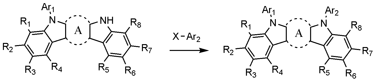
상기 반응식 1에서, X를 제외한 나머지 정의는 앞서 정의한 바와 같으며, X는 할로겐이고 보다 바람직하게는 클로로 또는 브로모이다. In
상기 반응식 1은 아민 치환 반응으로서, 팔라듐 촉매와 염기 존재 하에 수행하는 것이 바람직하며, 아민 치환 반응을 위한 반응기는 당업계에 알려진 바에 따라 변경이 가능하다. 상기 제조 방법은 후술할 제조예에서 보다 구체화될 수 있다.
상기 화학식 2로 표시되는 화합물은 하기 반응식 2와 같은 방법으로 제조될 수 있다.The compound represented by
[반응식 2][Scheme 2]
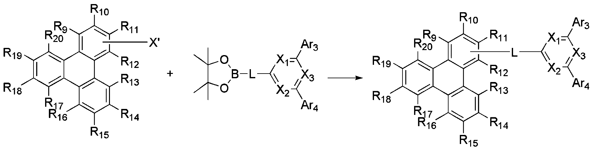
상기 반응식 2에서, X’를 제외한 나머지 정의는 앞서 정의한 바와 같으며, X'은 할로겐이고 보다 바람직하게는 클로로 또는 브로모이다. In
상기 반응은 스즈키 커플링 반응으로서, 팔라듐 촉매와 염기 존재 하에 수행하는 것이 바람직하며, 스즈키 커플링 반응을 위한 반응기는 당업계에 알려진 바에 따라 변경이 가능하다. 상기 제조 방법은 후술할 제조예에서 보다 구체화될 수 있다.The reaction is a Suzuki coupling reaction, preferably carried out in the presence of a palladium catalyst and a base, and the reactor for the Suzuki coupling reaction can be changed as known in the art. The manufacturing method may be more specific in the manufacturing examples to be described later.
한편, 도펀트 재료로는 방향족 아민 유도체, 스트릴아민 화합물, 붕소 착체, 플루오란텐 화합물, 금속 착체 등이 있다. 구체적으로 방향족 아민 유도체로는 치환 또는 비치환된 아릴아미노기를 갖는 축합 방향족환 유도체로서, 아릴아미노기를 갖는 피렌, 안트라센, 크리센, 페리플란텐 등이 있으며, 스티릴아민 화합물로는 치환 또는 비치환된 아릴아민에 적어도 1개의 아릴비닐기가 치환되어 있는 화합물로, 아릴기, 실릴기, 알킬기, 사이클로알킬기 및 아릴아미노기로 이루어진 군에서 1 또는 2 이상 선택되는 치환기가 치환 또는 비치환된다. 구체적으로 스티릴아민, 스티릴디아민, 스티릴트리아민, 스티릴테트라아민 등이 있으나, 이에 한정되지 않는다. 또한, 금속 착체로는 이리듐 착체, 백금 착체 등이 있으나, 이에 한정되지 않는다.Meanwhile, examples of the dopant material include aromatic amine derivatives, strylamine compounds, boron complexes, fluoranthene compounds, and metal complexes. Specifically, the aromatic amine derivative is a condensed aromatic ring derivative having a substituted or unsubstituted arylamino group, and includes pyrene, anthracene, chrysene, periflanthene and the like having an arylamino group, and the styrylamine compound is substituted or unsubstituted As a compound in which at least one arylvinyl group is substituted on the arylamine, one or two or more substituents selected from the group consisting of aryl group, silyl group, alkyl group, cycloalkyl group, and arylamino group are substituted or unsubstituted. Specifically, there are styrylamine, styryldiamine, styryltriamine, and styryltetraamine, but are not limited thereto. In addition, examples of the metal complex include, but are not limited to, an iridium complex and a platinum complex.
(전자수송층)(Electron transport layer)
본 발명에 따른 유기 발광 소자는 상기 발광층 상에 전자수송층을 포함할 수 있다. The organic light-emitting device according to the present invention may include an electron transport layer on the emission layer.
상기 전자수송층은 전자주입층으로부터 전자를 수취하여 발광층까지 전자를 수송하는 층으로 전자 수송 물질로는 음극으로부터 전자를 잘 주입 받아 발광층으로 옮겨줄 수 있는 물질로서, 전자에 대한 이동성이 큰 물질이 적합하다. 구체적인 예로는 8-히드록시퀴놀린의 Al 착물; Alq 3를 포함한 착물; 유기 라디칼 화합물; 히드록시플라본-금속 착물 등이 있으나, 이들에만 한정되는 것은 아니다. 전자 수송층은 종래기술에 따라 사용된 바와 같이 임의의 원하는 캐소드 물질과 함께 사용할 수 있다. 특히, 적절한 캐소드 물질의 예는 낮은 일함수를 가지고 알루미늄층 또는 실버층이 뒤따르는 통상적인 물질이다. 구체적으로 세슘, 바륨, 칼슘, 이테르븀 및 사마륨이고, 각 경우 알루미늄 층 또는 실버층이 뒤따른다.The electron transport layer is a layer that receives electrons from the electron injection layer and transports electrons to the emission layer. As an electron transport material, a material capable of injecting electrons from the cathode and transferring them to the emission layer, and a material having high mobility for electrons is suitable. Do. Specific examples include Al complex of 8-hydroxyquinoline; Complexes containing Alq 3; Organic radical compounds; Hydroxyflavone-metal complexes and the like, but are not limited thereto. The electron transport layer can be used with any desired cathode material as used according to the prior art. In particular, examples of suitable cathode materials are conventional materials that have a low work function and are followed by an aluminum layer or a silver layer. Specifically, they are cesium, barium, calcium, ytterbium, and samarium, and in each case an aluminum layer or a silver layer follows.
(전자주입층)(Electron injection layer)
본 발명에 따른 유기 발광 소자는 필요에 따라 전자수송층(또는 발광층) 및 음극 사이에 전자주입층을 포함할 수 있다. The organic light emitting device according to the present invention may include an electron injection layer between an electron transport layer (or a light emitting layer) and a cathode, if necessary.
상기 전자주입층은 전극으로부터 전자를 주입하는 층으로, 전자를 수송하는 능력을 갖고, 음극으로부터의 전자 주입 효과, 발광층 또는 발광 재료에 대하여 우수한 전자주입 효과를 가지며, 발광층에서 생성된 여기자의 정공주입층에의 이동을 방지하고, 또한, 박막형성능력이 우수한 화합물이 바람직하다. 구체적으로는 플루오레논, 안트라퀴노다이메탄, 다이페노퀴논, 티오피란 다이옥사이드, 옥사졸, 옥사다이아졸, 트리아졸, 이미다졸, 페릴렌테트라카복실산, 프레오레닐리덴 메탄, 안트론 등과 그들의 유도체, 금속 착체 화합물 및 질소 함유 5원환 유도체 등이 있으나, 이에 한정되지 않는다. The electron injection layer is a layer that injects electrons from the electrode, has the ability to transport electrons, has an electron injection effect from the cathode, an excellent electron injection effect for the light emitting layer or the light emitting material, and hole injection of excitons generated in the light emitting layer A compound that prevents migration to the layer and is excellent in thin film forming ability is preferable. Specifically, fluorenone, anthraquinodimethane, diphenoquinone, thiopyran dioxide, oxazole, oxadiazole, triazole, imidazole, perylene tetracarboxylic acid, preorenylidene methane, anthrone, etc. Complex compounds and nitrogen-containing 5-membered ring derivatives, but are not limited thereto.
상기 금속 착체 화합물로서는 8-하이드록시퀴놀리나토 리튬, 비스(8-하이드록시퀴놀리나토)아연, 비스(8-하이드록시퀴놀리나토)구리, 비스(8-하이드록시퀴놀리나토)망간, 트리스(8-하이드록시퀴놀리나토)알루미늄, 트리스(2-메틸-8-하이드록시퀴놀리나토)알루미늄, 트리스(8-하이드록시퀴놀리나토)갈륨, 비스(10-하이드록시벤조[h]퀴놀리나토)베릴륨, 비스(10-하이드록시벤조[h]퀴놀리나토)아연, 비스(2-메틸-8-퀴놀리나토)클로로갈륨, 비스(2-메틸-8-퀴놀리나토)(o-크레졸라토)갈륨, 비스(2-메틸-8-퀴놀리나토)(1-나프톨라토)알루미늄, 비스(2-메틸-8-퀴놀리나토)(2-나프톨라토)갈륨 등이 있으나, 이에 한정되지 않는다.Examples of the metal complex compound include 8-hydroxyquinolinato lithium, bis(8-hydroxyquinolinato)zinc, bis(8-hydroxyquinolinato)copper, bis(8-hydroxyquinolinato)manganese, Tris(8-hydroxyquinolinato)aluminum, tris(2-methyl-8-hydroxyquinolinato)aluminum, tris(8-hydroxyquinolinato)gallium, bis(10-hydroxybenzo[h] Quinolinato)beryllium, bis(10-hydroxybenzo[h]quinolinato)zinc, bis(2-methyl-8-quinolinato)chlorogallium, bis(2-methyl-8-quinolinato)( o-cresolato)gallium, bis(2-methyl-8-quinolinato)(1-naphtholato)aluminum, bis(2-methyl-8-quinolinato)(2-naphtholato)gallium, etc. It is not limited to this.
(유기 발광 소자)(Organic Light-Emitting Element)
본 발명에 따른 유기 발광 소자는, 기판 상에 양극, 1층 이상의 유기물층 및 음극이 순차적으로 적층된 구조(normal type)의 유기 발광 소자일 수 있다. 또한, 본 발명에 따른 유기 발광 소자는 기판 상에 음극, 1층 이상의 유기물층 및 양극이 순차적으로 적층된 역방향 구조(inverted type)의 유기 발광 소자일 수 있다. 예컨대, 본 발명의 일실시예에 따른 유기 발광 소자의 구조는 도 1 및 2에 예시되어 있다.The organic light-emitting device according to the present invention may be a normal type organic light-emitting device in which an anode, one or more organic material layers, and a cathode are sequentially stacked on a substrate. In addition, the organic light-emitting device according to the present invention may be an inverted type organic light-emitting device in which a cathode, one or more organic material layers, and an anode are sequentially stacked on a substrate. For example, the structure of an organic light-emitting device according to an embodiment of the present invention is illustrated in FIGS. 1 and 2.
도 1은 기판(1), 양극(2), 정공수송층(3), 발광층(4), 전자수송층(5), 및 음극(6)으로 이루어진 유기 발광 소자의 예를 도시한 것이다. 이와 같은 구조에 있어서, 상기 화학식 1 및 화학식 2로 표시되는 화합물이 상기 발광층에 포함될 수 있다. 1 shows an example of an organic light-emitting device comprising a
도 2는 기판 (1), 양극(2), 정공주입층(7), 정공수송층(3), 발광층(4), 전자수송층(5), 전자주입층(8) 및 음극(6)로 이루어진 유기 발광 소자의 예를 도시한 것이다. 이와 같은 구조에 있어서, 상기 화학식 1 및 화학식 2로 표시되는 화합물이 상기 발광층에 포함될 수 있다.2 is a substrate (1), an anode (2), a hole injection layer (7), a hole transport layer (3), a light emitting layer (4), an electron transport layer (5), an electron injection layer (8) and a cathode (6). It shows an example of an organic light-emitting device. In such a structure, the compounds represented by
본 발명에 따른 유기 발광 소자는, 상술한 소재를 사용하는 것을 제외하고는, 당 기술분야에 알려져 있는 재료와 방법으로 제조할 수 있다.The organic light-emitting device according to the present invention can be manufactured by materials and methods known in the art, except for using the above-described materials.
예컨대, 본 발명에 따른 유기 발광 소자는 기판 상에 양극, 유기물층 및 음극을 순차적으로 적층시켜 제조할 수 있다. 이때, 스퍼터링법(sputtering)이나 전자빔 증발법(e-beam evaporation)과 같은 PVD(physical Vapor Deposition) 방법을 이용하여, 기판 상에 금속 또는 전도성을 가지는 금속 산화물 또는 이들의 합금을 증착시켜 양극을 형성하고, 그 위에 정공주입층, 정공수송층, 발광층 및 전자수송층을 포함하는 유기물 층을 형성한 후, 그 위에 음극으로 사용할 수 있는 물질을 증착시켜 제조할 수 있다. For example, the organic light emitting device according to the present invention may be manufactured by sequentially laminating an anode, an organic material layer, and a cathode on a substrate. At this time, by using a PVD (physical vapor deposition) method such as sputtering or e-beam evaporation, a metal or a conductive metal oxide or an alloy thereof is deposited on the substrate to form an anode. And, after forming an organic material layer including a hole injection layer, a hole transport layer, a light emitting layer and an electron transport layer thereon, it can be prepared by depositing a material that can be used as a cathode thereon.
이와 같은 방법 외에도, 기판 상에 음극 물질로부터 유기물층, 양극 물질을 차례로 증착시켜 유기 발광 소자를 제조할 수 있다(WO 2003/012890). 다만, 제조 방법이 이에 한정되는 것은 아니다. In addition to such a method, an organic light emitting device may be manufactured by sequentially depositing an organic material layer and an anode material from a cathode material on a substrate (WO 2003/012890). However, the manufacturing method is not limited thereto.
이와 같은 방법 외에도, 기판 상에 음극 물질로부터 유기물층, 양극 물질을 차례로 증착시켜 유기 발광 소자를 제조할 수 있다(WO 2003/012890). 다만, 제조 방법이 이에 한정되는 것은 아니다. In addition to such a method, an organic light emitting device may be manufactured by sequentially depositing an organic material layer and an anode material from a cathode material on a substrate (WO 2003/012890). However, the manufacturing method is not limited thereto.
본 발명에 따른 유기 발광 소자는 사용되는 재료에 따라 전면 발광형, 후면 발광형 또는 양면 발광형일 수 있다.The organic light-emitting device according to the present invention may be a top emission type, a bottom emission type, or a double-sided emission type depending on the material used.
또한, 본 발명에 따른 화합물은 유기 발광 소자 외에도 유기 태양 전지 또는 유기 트랜지스터에 포함될 수 있다.Further, the compound according to the present invention may be included in an organic solar cell or an organic transistor in addition to the organic light emitting device.
상술한 본 발명에 따른 유기 발광 소자의 제조는 이하 실시예에서 구체적으로 설명한다. 그러나 하기 실시예는 본 발명을 예시하기 위한 것이며, 본 발명의 범위가 이들에 의하여 한정되는 것은 아니다.The fabrication of the organic light-emitting device according to the present invention described above will be described in detail in the following examples. However, the following examples are for illustrating the present invention, and the scope of the present invention is not limited thereto.
[합성예][Synthesis Example]
합성예 1-1: 화합물 1-2의 합성Synthesis Example 1-1: Synthesis of Compound 1-2
단계 1) 중간체 B의 합성Step 1) Synthesis of Intermediate B
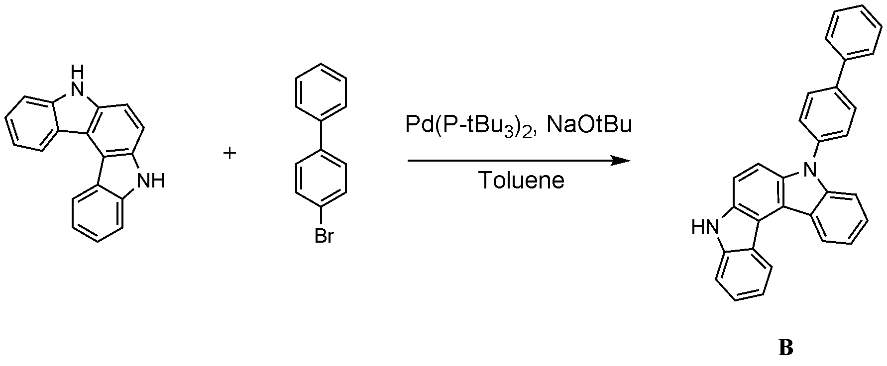
질소 분위기에서 화합물 5,8-다이하이드로인돌로[2,3-c]카바졸 (20 g, 78.0 mmol), 4-브로모-1,1'-비페닐(18.2 g, 78.0 mmol), 비스(트리-t-부틸포스핀) 팔라듐(0) (1.19 g, 2.3mmol), 소듐 t-부톡사이드 (15.00 g, 156 mmol)을 자일렌 450 mL에 넣고 5 시간 동안 가열 교반하였다. 상온으로 온도를 낮추고 생성된 고체를 여과 후 물과 에틸아세테이트로 씻어주었다. 고체를 클로로포름으로 녹여 물로 씻어주고 황산마그네슘과 산성백토를 넣고 교반 후 여과하여 감압농축 시켰다. 이 후 클로로포름과 에틸아세테이트를 이용해 재결정하여 흰색의 고체 화합물 1-2을 제조하였다(20.0 g, 63%, MS: [M+H]
+ =409).
단계 2) 화합물 1-2의 합성Step 2) Synthesis of Compound 1-2
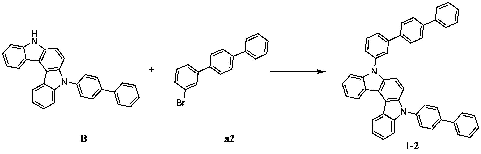
합성예 1-2: 화합물 1-1의 합성Synthesis Example 1-2: Synthesis of Compound 1-1
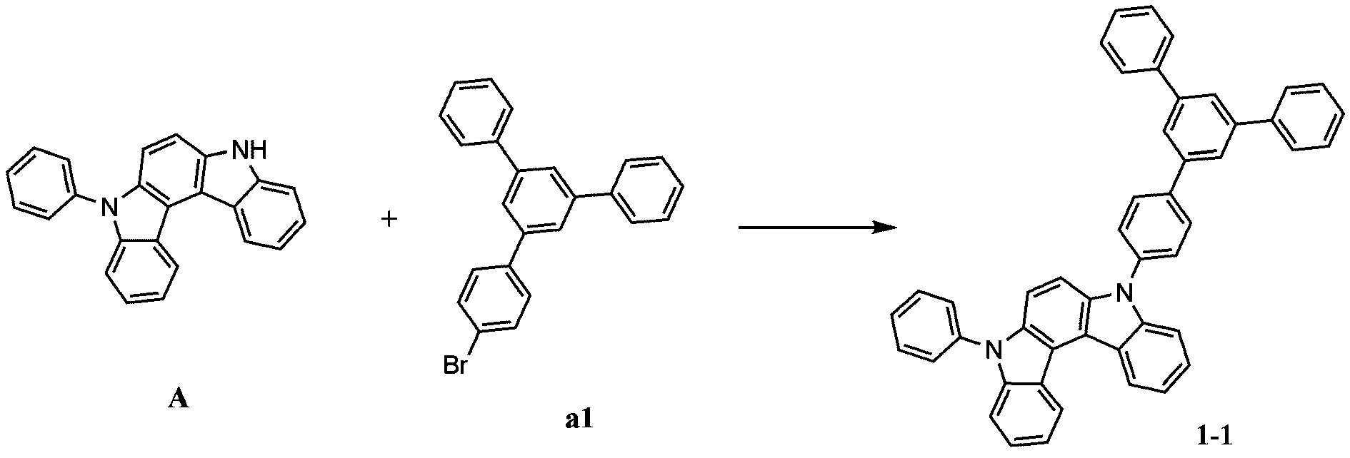
합성예 1-1의 단계 2에서, 화합물 B 대신 하기 화합물 A를, 화합물 a2 대신 화합물 a1을 사용한 것을 제외하고는, 화합물 1-2의 제조방법과 동일한 방법으로 화합물 1-1을 합성하였다(MS: [M+H]
+=637).In
합성예 1-3: 화합물 1-5의 합성Synthesis Example 1-3: Synthesis of Compound 1-5

합성예 1-1의 단계 2에서, 화합물 B 대신 화합물 C를 사용한 것을 제외하고는, 화합물 1-2의 제조방법과 동일한 방법으로 화합물 1-5를 합성하였다(MS: [M+H]
+=561).In
합성예 1-4: 화합물 1-7의 합성Synthesis Example 1-4: Synthesis of Compound 1-7

합성예 1-1의 단계 2에서, 화합물 a2 대신 4-브로모-1,1'-비페닐을 사용한 것을 제외하고는, 화합물 1-2의 제조방법과 동일한 방법으로 화합물 1-7를 합성하였다(MS: [M+H]
+=561).In
합성예 1-5: 화합물 1-8의 합성Synthesis Example 1-5: Synthesis of Compound 1-8
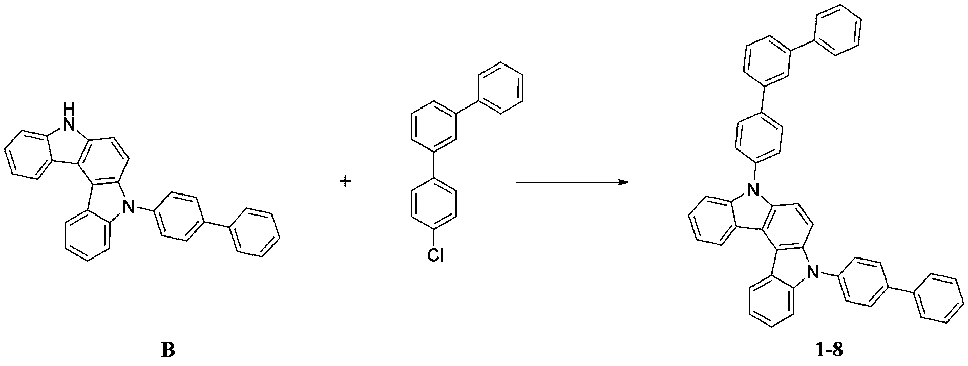
합성예 1-1의 단계 2에서, 화합물 a2 대신 4-클로로-1,1':3',1''-터페닐을 사용한 것을 제외하고는, 화합물 1-2의 제조방법과 동일한 방법으로 화합물 1-8를 합성하였다(MS: [M+H]
+=637).In
합성예 1-6: 화합물 1-9의 합성Synthesis Example 1-6: Synthesis of Compound 1-9

합성예 1-1의 단계 2에서, 화합물 a2 대신 5'-클로로-1,1':3',1''-터페닐을 사용한 것을 제외하고는, 화합물 1-2의 제조방법과 동일한 방법으로 화합물 1-9를 합성하였다(MS: [M+H]
+=637).In
합성예 1-7: 화합물 1-25의 합성Synthesis Example 1-7: Synthesis of Compound 1-25
단계 1) 화합물 D의 합성Step 1) Synthesis of Compound D

합성예 1-1의 단계 1에서, 5,8-다이하이드로인돌로[2,3-c]카바졸 대신 5,7-다이하이드로인돌로[2,3-b]카바졸을 사용한 것을 제외하고는, 화합물 B의 제조방법과 동일한 방법으로 화합물 D를 합성하였다(MS: [M+H]
+=409).Except that in
단계 2) 화합물 1-25의 합성Step 2) Synthesis of Compound 1-25

합성예 1-1의 단계 2에서, 화합물 B 와 화합물 a2 대신 화합물 D와 5'-클로로-1,1':3',1''-터페닐을 사용한 것을 제외하고는, 화합물 1-2의 제조방법과 동일한 방법으로 화합물 1-25를 합성하였다(MS: [M+H]
+=637).In
합성예 1-8: 화합물 1-15의 합성Synthesis Example 1-8: Synthesis of Compound 1-15

합성예 1-1의 단계 2에서, 화합물B 대신 하기 5-페닐-5,11-다이하이드로인돌로[3,2-b]카바졸을 사용한 것을 제외하고는, 화합물 1-2의 제조방법과 동일한 방법으로 화합물 1-15를 합성하였다(MS: [M+H]
+=561).In
합성예 1-9: 화합물 1-13의 합성Synthesis Example 1-9: Synthesis of Compound 1-13
단계 1) 화합물 E의 합성Step 1) Synthesis of Compound E

합성예 1-1의 단계 1에서, 5,8-다이하이드로인돌로[2,3-c]카바졸 대신 5,11-다이하이드로인돌로[3,2-b]카바졸을 사용한 것을 제외하고는, 화합물 B의 제조방법과 동일한 방법으로 화합물 E를 합성하였다(MS: [M+H]
+=409).In
단계 2) 화합물 1-13의 합성Step 2) Synthesis of Compound 1-13
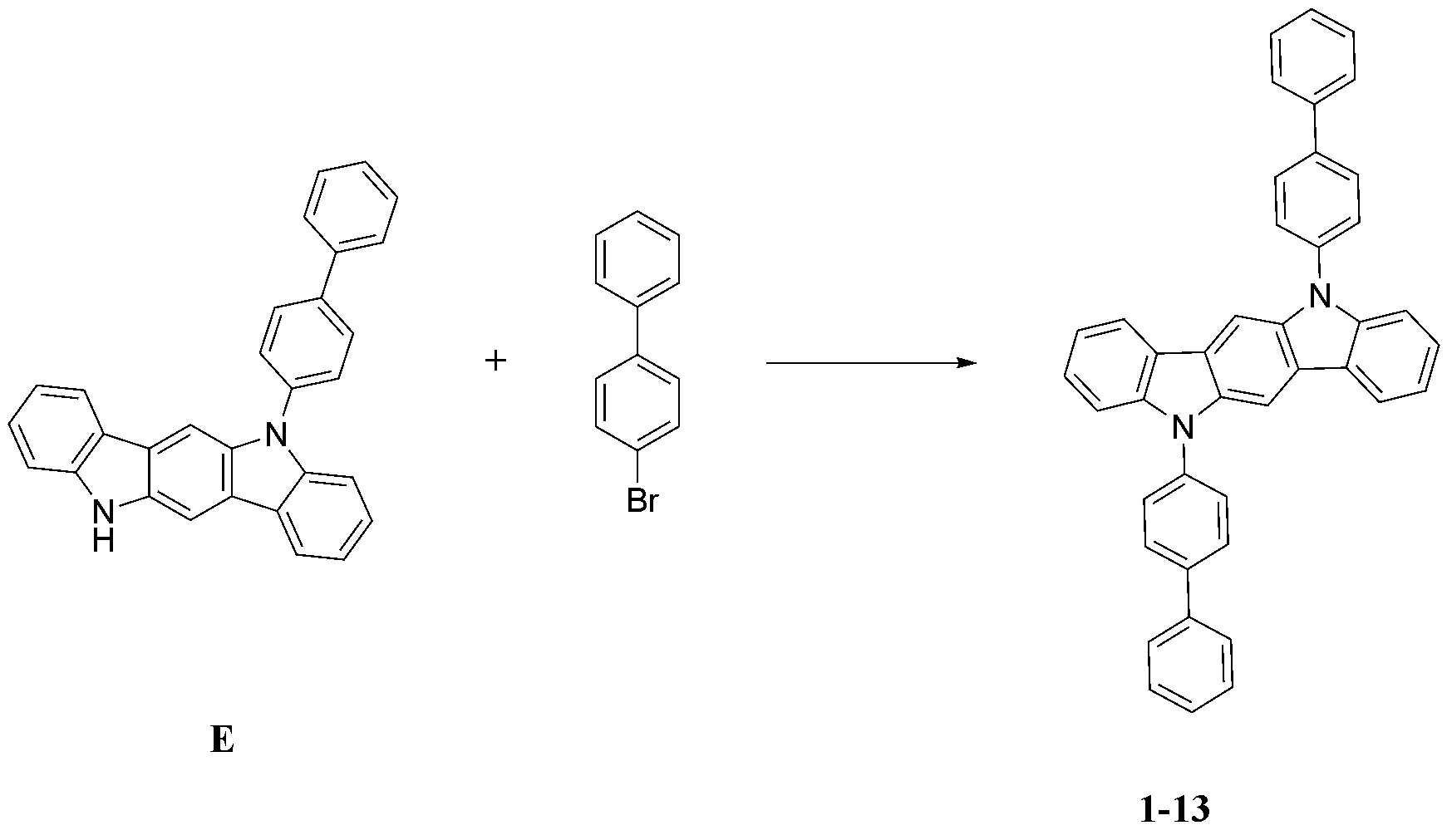
합성예 1-1의 단계 2에서, 화합물 B 와 화합물 a2 대신 화합물 E와 4-브로모-1,1'-비페닐을 사용한 것을 제외하고는, 화합물 1-2의 제조방법과 동일한 방법으로 화합물 1-13을 합성하였다(MS: [M+H]
+=561).In
합성예 1-10: 화합물 1-20의 합성Synthesis Example 1-10: Synthesis of Compound 1-20
단계 1) 중간체 F의 합성Step 1) Synthesis of Intermediate F

합성예 1-1의 단계 1에서, 5,8-다이하이드로인돌로[2,3-c]카바졸 대신 5,12-다이하이드로인돌로[3,2-a]카바졸을 사용한 것을 제외하고는, 화합물 B의 제조방법과 동일한 방법으로 화합물 F를 합성하였다(MS: [M+H]
+=409).In
단계 2) 화합물 1-20의 합성Step 2) Synthesis of Compound 1-20

합성예 1-1의 단계 2에서, 화합물 B 와 화합물 a2 대신 화합물 E와 4-브로모-1,1'-비페닐을 사용한 것을 제외하고는, 화합물 1-2의 제조방법과 동일한 방법으로 화합물 1-20을 합성하였다(MS: [M+H]
+=561).In
합성예 2-1: 화합물 2-1의 합성Synthesis Example 2-1: Synthesis of Compound 2-1

단계 1) 화합물 P-1의 합성Step 1) Synthesis of Compound P-1
1-브로모-3-플루오로-2-요오드벤젠(1-bromo-3-fluoro-2-iodobenzene)(100 g, 333.5 mmol), 5-클로로-2-메톡시페닐보론산((5-chloro-2-methoxyphenyl)boronic acid)(62.2 g, 333.5 mmol)를 테트라하이드로퓨란(THF) 800 mL에 녹였다. 여기에 탄산나트륨(Na 2CO 3) 2 M 용액(500 mL), 테트라키스(트리페닐포스핀)팔라듐(0) [Pd(PPh 3) 4](7.7 g, 6.7 mmol)을 넣고 12 시간 환류시켰다. 반응이 끝난 후 상온으로 냉각시키고, 생성된 혼합물을 물과 톨루엔으로 3회 추출하였다. 톨루엔층을 분리한 뒤 황산마그네슘(magnesium sulfate)으로 건조하여 여과한 여액을 감압증류하여 얻은 혼합물을 클로로폼, 에탄올을 이용해 3회 재결정 하여 화합물 P-1(53.7 g, 수율 51 %;MS: [M+H] +=314)을 얻었다.1-bromo-3-fluoro-2-iodobenzene (100 g, 333.5 mmol), 5-chloro-2-methoxyphenylboronic acid ((5- Chloro-2-methoxyphenyl)boronic acid) (62.2 g, 333.5 mmol) was dissolved in 800 mL of tetrahydrofuran (THF). Sodium carbonate (Na 2 CO 3 ) 2 M solution (500 mL), tetrakis (triphenylphosphine) palladium (0) [Pd(PPh 3 ) 4 ] (7.7 g, 6.7 mmol) was added and refluxed for 12 hours. . After the reaction was completed, the mixture was cooled to room temperature, and the resulting mixture was extracted three times with water and toluene. After separating the toluene layer, the mixture obtained by drying with magnesium sulfate and distilling the filtered filtrate under reduced pressure was recrystallized three times using chloroform and ethanol, and compound P-1 (53.7 g, yield 51%; MS: [ M+H] + =314) was obtained.
단계 2) 화합물 P-2의 합성Step 2) Synthesis of Compound P-2
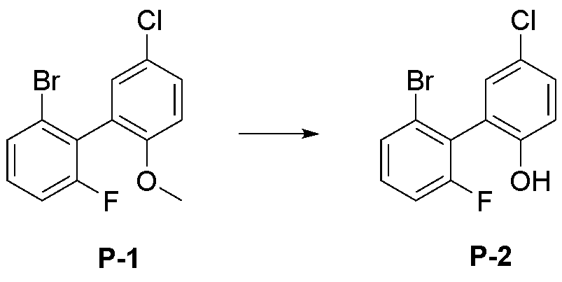
화합물 P-1(50.0 g, 158.5 mmol)을 디클로로메탄(Dichlorometahne)(600 mL)에 녹인 뒤 0 ℃로 냉각시킨다. 보론트리브로마이드(boron tribromide)(15.8 mL, 166.4 mmol)를 천천히 적가한 뒤 12시간 동안 교반하였다. 반응이 종료된 후 물로 3회 세척하고, 황산마그네슘(magnesium sulfate)으로 건조하여 여과한 여액을 감압증류하고 컬럼크로마토크래피로 정제하여 화합물 P-2(47.4 g, 수율 99 %;MS: [M+H] +=300)을 얻었다.Compound P-1 (50.0 g, 158.5 mmol) was dissolved in dichloromethane (600 mL) and cooled to 0 °C. Boron tribromide (15.8 mL, 166.4 mmol) was slowly added dropwise, followed by stirring for 12 hours. After the reaction was completed, the filtrate was washed three times with water, dried over magnesium sulfate, and filtered, distilled under reduced pressure, and purified by column chromatography to obtain compound P-2 (47.4 g, yield 99%; MS: [M +H] + =300) was obtained.
단계 3) 화합물 P-3의 합성Step 3) Synthesis of Compound P-3

화합물 P-2(40.0 g, 132.7 mmol)을 증류된 다이메틸포름아마이드(DMF)(400 mL)에 녹였다. 이를 0 ℃로 냉각시키고, 여기에 나트륨 하이드리드(sodium hydride)(3.5 g, 145.9 mmol)를 천천히 적가하였다. 20분 동안 교반한 뒤 100℃에서 1시간 동안 교반하였다. 반응이 종료된 후 상온으로 냉각하고, 에탄올(Ethanol) 100 mL을 천천히 넣었다. 위 혼합물을 감압증류 하여 얻은 혼합물을 클로로포름, 에틸아세테이트로 재결정하여 화합물 P-3(30.3 g, 수율 81 %;MS: [M+H] +=280)을 얻었다.Compound P-2 (40.0 g, 132.7 mmol) was dissolved in distilled dimethylformamide (DMF) (400 mL). This was cooled to 0° C., and sodium hydride (3.5 g, 145.9 mmol) was slowly added dropwise thereto. After stirring for 20 minutes, the mixture was stirred at 100°C for 1 hour. After the reaction was completed, it was cooled to room temperature, and 100 mL of ethanol was slowly added thereto. The mixture obtained by distilling the mixture under reduced pressure was recrystallized with chloroform and ethyl acetate to obtain compound P-3 (30.3 g, yield 81%; MS: [M+H] + =280).
단계 4) 화합물 P-4의 합성Step 4) Synthesis of Compound P-4
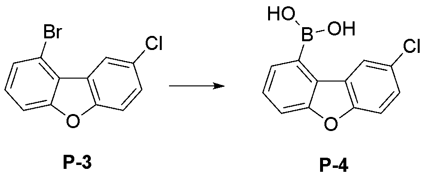
화합물 P-3(30.0 g, 106.6 mmol)을 테트라하이드로퓨란(300 mL)에 녹인 후, -78 ℃로 온도를 낮추고 1.7 M 터셔리-부틸리튬(t-BuLi)(62.7 mL, 106.6 mmol)을 천천히 가하였다. 동일 온도에서 한 시간 동안 교반한 후 트리아이소프로필보레이트(B(OiPr) 3)(28.3 mL, 213.1 mmol)을 가하고, 상온으로 온도를 서서히 올리면서 3시간동안 교반하였다. 반응 혼합물에 2 N 염산수용액(200 mL)을 가하고 1.5 시간 동안 상온에서 교반하였다. 생성된 침전물을 거르고 물과 에틸에테르(ethyl ether)로 차례로 씻은 후 진공 건조하였다. 건조 후 에틸에테르에 분산시켜 두 시간 동안 교반한 후 여과하고 건조하여 화합물 P-4(24.4 g, 수율 93 %; MS: [M+H] +=247)을 제조하였다.After dissolving compound P-3 (30.0 g, 106.6 mmol) in tetrahydrofuran (300 mL), lowering the temperature to -78 °C and adding 1.7 M tertiary-butyllithium (t-BuLi) (62.7 mL, 106.6 mmol). It was added slowly. After stirring at the same temperature for 1 hour, triisopropylborate (B(OiPr) 3 ) (28.3 mL, 213.1 mmol) was added, and the mixture was stirred for 3 hours while gradually raising the temperature to room temperature. 2N aqueous hydrochloric acid solution (200 mL) was added to the reaction mixture, followed by stirring at room temperature for 1.5 hours. The resulting precipitate was filtered, washed sequentially with water and ethyl ether, and dried under vacuum. After drying, the mixture was dispersed in ethyl ether, stirred for two hours, filtered, and dried to prepare compound P-4 (24.4 g, yield 93%; MS: [M+H] + =247).
단계 5) 화합물 P-5의 합성Step 5) Synthesis of Compound P-5

화합물 P-4(20.0 g, 81.2 mmol)과 2-chloro-4,6-diphenyl-1,3,5-triazine(21.8 g, 81.2 mmol)을 테트라하이드로퓨란(250 mL)에 분산시킨 후, 2M 탄산칼륨수용액(aq. K 2CO 3)(33.6 mL, 243.5 mmol)을 첨가하고 테트라키스트리페닐포스피노팔라듐[Pd(PPh 3) 4](1.9 g, 2 mol%)을 넣은 후 4시간 동안 교반 환류하였다. 상온으로 온도를 낮추고 생성된 고체를 여과하였다. 여과된 고체를 테트라하이드로퓨란과 에틸아세테이트로 재결정하고 여과한 뒤, 건조하여 화합물 P-5(32.4 g, 수율 92 %; MS: [M+H] +=434)를 제조하였다.Compound P-4 (20.0 g, 81.2 mmol) and 2-chloro-4,6-diphenyl-1,3,5-triazine (21.8 g, 81.2 mmol) were dispersed in tetrahydrofuran (250 mL), and then 2M After adding an aqueous potassium carbonate solution (aq. K 2 CO 3 ) (33.6 mL, 243.5 mmol) and adding tetrakistriphenylphosphinopalladium [Pd(PPh 3 ) 4 ] (1.9 g, 2 mol%), for 4 hours It was stirred and refluxed. The temperature was lowered to room temperature and the resulting solid was filtered. The filtered solid was recrystallized with tetrahydrofuran and ethyl acetate, filtered, and dried to prepare compound P-5 (32.4 g, yield 92%; MS: [M+H] + =434).
단계 6) 화합물 P-6의 합성Step 6) Synthesis of Compound P-6
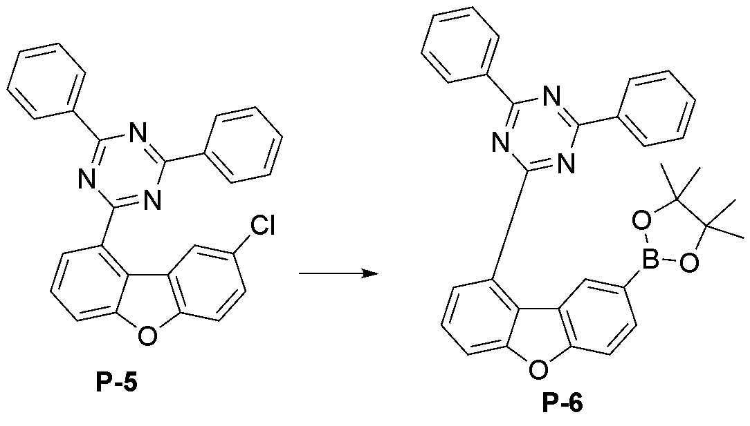
화합물 P-5(30 g, 69.2 mmol) 비스(피나콜라토)디보론(Bis(pinacolato)diborone)(19.3 g, 76.1 mmol) 포타슘아세테이트(potassium acetate)(20.4 g, 207.5 mmol), 테트라키스트리페닐포스피노팔라듐(0) [Pd(PPh 3) 4](1.6 g, 2 mol%)을 테트라하이드로퓨란(300 mL) 에 넣고 12시간 동안 환류시켰다. 반응이 종료된 후 상온으로 식힌 뒤 감압 증류하여 용매를 제거하였다. 이것을 클로로포름(Chloroform)에 녹이고 물로 3회 씻어낸 뒤 유기층을 분리하여 황산 마그네슘(Magnesium sulfate)으로 건조하였다. 이를 감압 증류하여 화합물 P-6(34.5 g, 수율 95 %; MS: [M+H] +=526)을 제조하였다.Compound P-5 (30 g, 69.2 mmol) Bis (pinacolato) diborone (19.3 g, 76.1 mmol) potassium acetate (20.4 g, 207.5 mmol), tetrakistri Phenylphosphinopalladium (0) [Pd(PPh 3 ) 4 ] (1.6 g, 2 mol%) was added to tetrahydrofuran (300 mL) and refluxed for 12 hours. After the reaction was completed, the mixture was cooled to room temperature and distilled under reduced pressure to remove the solvent. This was dissolved in chloroform, washed three times with water, and then the organic layer was separated and dried over magnesium sulfate. This was distilled under reduced pressure to prepare compound P-6 (34.5 g, yield 95%; MS: [M+H] + =526).
단계 7) 화합물 2-1의 합성Step 7) Synthesis of compound 2-1
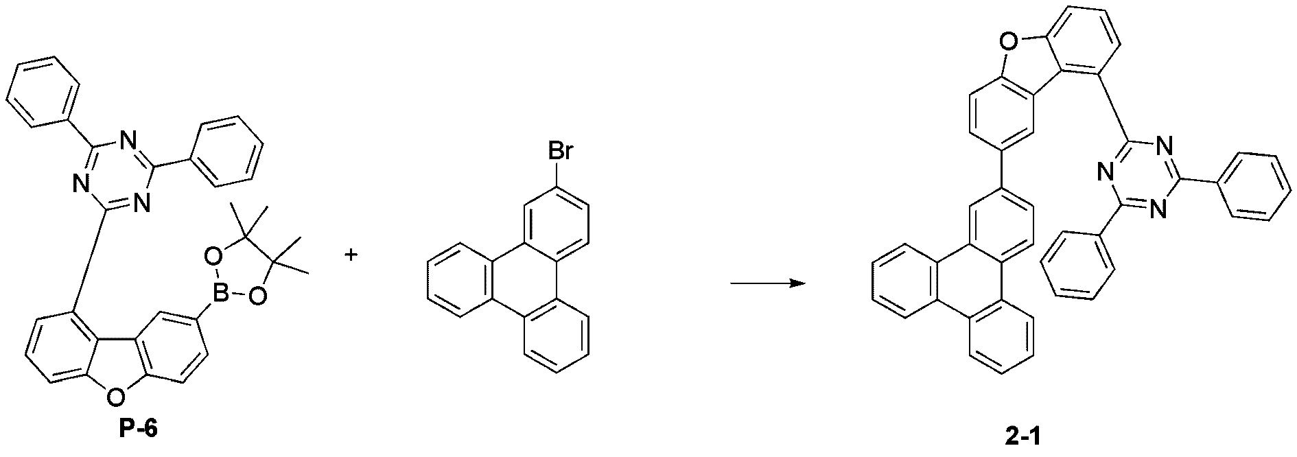
화합물 P-6(20.0 g, 38.1 mmol)과 2-bromo tripheylene (11.7 g, 38.1 mmol)을 테트라하이드로퓨란(250 mL)에 분산시킨 후, 2M 탄산칼륨수용액(aq. K 2CO 3)(38.1 mL, 76.2 mmol)을 첨가하고 테트라키스트리페닐포스피노팔라듐[Pd(PPh 3) 4](1.3 g, 3 mol%)을 넣은 후 4시간 동안 교반 환류하였다. 상온으로 온도를 낮추고 생성된 고체를 여과하였다. 여과된 고체를 테트라하이드로퓨란과 에틸아세테이트로 재결정하고 여과한 뒤, 건조하여 화합물 2-1(14.5 g, 수율 61 %; MS: [M+H] +=626)를 제조하였다.Compound P-6 (20.0 g, 38.1 mmol) and 2-bromo tripheylene (11.7 g, 38.1 mmol) were dispersed in tetrahydrofuran (250 mL), followed by 2M aqueous potassium carbonate solution (aq. K 2 CO 3 ) (38.1 mL, 76.2 mmol) was added, and tetrakistriphenylphosphinopalladium [Pd(PPh 3 ) 4 ] (1.3 g, 3 mol%) was added, followed by stirring and refluxing for 4 hours. The temperature was lowered to room temperature and the resulting solid was filtered. The filtered solid was recrystallized with tetrahydrofuran and ethyl acetate, filtered, and dried to prepare compound 2-1 (14.5 g, yield 61%; MS: [M+H] + =626).
합성예 2-2: 화합물 2-2의 합성Synthesis Example 2-2: Synthesis of Compound 2-2
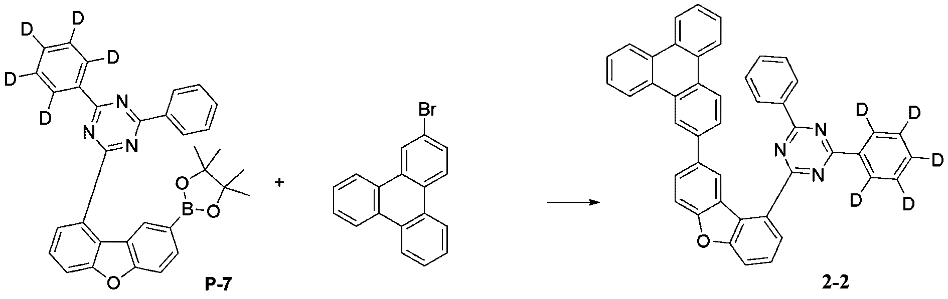
상기 합성예 2-1의 단계 7에서 화합물 P-6 대신 화합물 P-7을 사용한 것을 제외하고는 동일한 방법으로 화합물 2-2를 합성하였다(MS: [M+H]
+=631).Compound 2-2 was synthesized in the same manner as in
합성예 2-3: 화합물 2-6의 합성Synthesis Example 2-3: Synthesis of Compound 2-6

상기 합성예 2-1의 단계 7에서 화합물 P-6 대신 하기 화합물 P-8을 사용한 것을 제외하고는 동일한 방법으로 화합물 2-6을 합성하였다(MS: [M+H]
+= 701).In
합성예 2-4: 화합물 2-17의 합성Synthesis Example 2-4: Synthesis of Compound 2-17
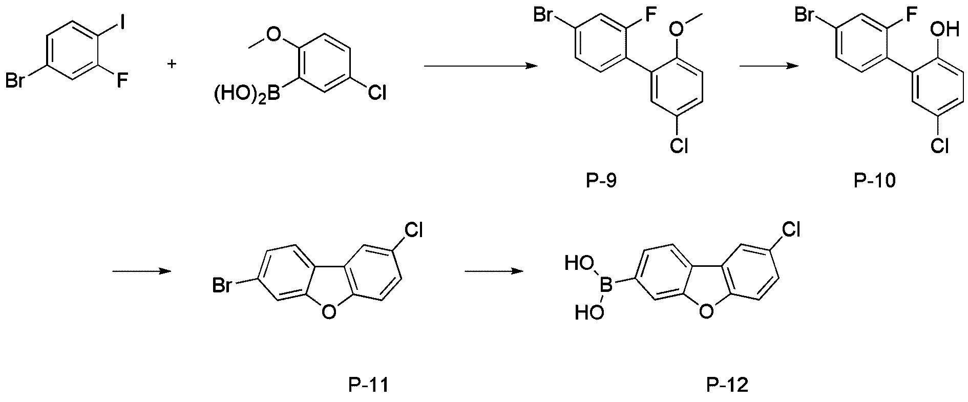
단계1) 화합물 P-9의 합성Step 1) Synthesis of Compound P-9
합성예 2-1의 단계 1에서 1-브로모-3-플루오로-2-요오드벤젠을 4-브로모-2-플루오로-1-아이오도벤젠으로 변경하여 사용한 것을 제외하고는, 화합물 2-1의 단계 1의 화합물 P-1의 제조 방법과 동일한 제조 방법으로 화합물 P-9를 제조하였다. (62.3 g, 수율 79%; MS: [M+H]
+=315)
단계2) 화합물 P-10의 합성Step 2) Synthesis of Compound P-10
합성예 2-1의 단계 2에서, 화합물 P-1 대신 하기 화합물 P-9를 사용한 것을 제외하고는, 화합물 2-1의 단계 2의 화합물 P-2의 제조방법과 동일한 방법으로 화합물 P-10을 합성하였다(51.7 g, 수율 87%; MS: [M+H]
+=300).In
단계3) 화합물 P-11의 합성Step 3) Synthesis of Compound P-11
합성예 2-1의 단계 3에서, 화합물 P-2 대신 하기 화합물 P-10를 사용한 것을 제외하고는, 화합물 2-1의 단계 3의 화합물 P-3의 제조방법과 동일한 방법으로 화합물 P-11를 합성하였다(41.8 g, 수율 87%; MS: [M+H]
+=280).In
단계4) 화합물 P-12의 합성Step 4) Synthesis of Compound P-12
합성예 2-1의 단계 4에서, 화합물 P-3 대신 하기 화합물 P-11를 사용한 것을 제외하고는, 화합물 2-1의 단계 4의 화합물 P-4의 제조방법과 동일한 방법으로 화합물 P-12를 합성하였다(31.2 g, 수율 85%; MS: [M+H]
+=247).In
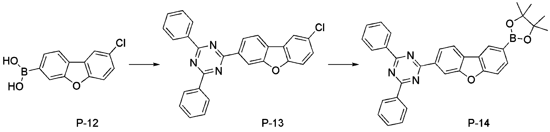
단계5) 화합물 P-13의 합성Step 5) Synthesis of Compound P-13
합성예 2-1의 단계 5에서, 화합물 P-4 대신 하기 화합물 P-12를 사용한 것을 제외하고는, 화합물 2-1의 단계 5의 화합물 P-5의 제조방법과 동일한 방법으로 화합물 P-13을 합성하였다(MS: [M+H]
+=434).In
단계6) 화합물 P-14의 합성Step 6) Synthesis of Compound P-14
합성예 2-1의 단계 6에서, 화합물 P-5 대신 하기 화합물 P-13을 사용한 것을 제외하고는, 화합물 2-1의 단계 6의 화합물 P-6의 제조방법과 동일한 방법으로 화합물 P-14을 합성하였다(MS: [M+H]
+=434).In
단계7) 화합물 2-17의 합성Step 7) Synthesis of compound 2-17

합성예 2-1의 단계 7에서, 화합물 P-6 대신 하기 화합물 P-14를 사용한 것을 제외하고는, 화합물 2-1의 단계7 의 화합물 2-1의 제조방법과 동일한 방법으로 화합물 2-17을 합성하였다(MS: [M+H]
+=626).In
합성예 2-5: 화합물 2-20의 합성Synthesis Example 2-5: Synthesis of Compound 2-20
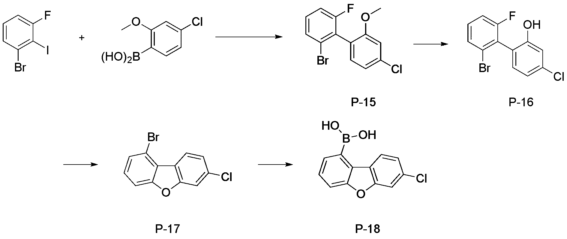
단계1) 화합물 P-15의 합성Step 1) Synthesis of Compound P-15
합성예 2-1의 단계 1에서 5-클로로-2-메톡시페닐보론산를 (4-클로로-2-메톡시페닐)보론산 으로 변경하여 사용한 것을 제외하고는, 화합물 2-1의 단계 1의 화합물 P-1의 제조 방법과 동일한 제조 방법으로 화합물 P-15를 제조하였다. (60.1 g, 수율 76%; MS: [M+H]
+=314)Except that in
단계2) 화합물 P-16의 합성Step 2) Synthesis of Compound P-16
합성예 2-1의 단계 2에서, 화합물 P-1 대신 하기 화합물 P-15를 사용한 것을 제외하고는, 화합물 2-1의 단계 2의 화합물 P-2의 제조방법과 동일한 방법으로 화합물 P-16을 합성하였다(54.0 g, 수율 94%; MS: [M+H]
+=300).In
단계3) 화합물 P-17의 합성Step 3) Synthesis of Compound P-17
합성예 2-1의 단계 3에서, 화합물 P-2 대신 하기 화합물 P-16을 사용한 것을 제외하고는, 화합물 2-1의 단계 3의 화합물 P-3의 제조방법과 동일한 방법으로 화합물 P-17를 합성하였다(42.2 g, 수율 83%; MS: [M+H]
+=280).In
단계4) 화합물 P-18의 합성Step 4) Synthesis of Compound P-18
합성예 2-1의 단계 4에서, 화합물 P-3 대신 하기 화합물 P-17를 사용한 것을 제외하고는, 화합물 2-1의 단계 4의 화합물 P-4의 제조방법과 동일한 방법으로 화합물 P-18를 합성하였다(34.1 g, 수율 92%; MS: [M+H]
+=247).In

단계5) 화합물 P-19의 합성Step 5) Synthesis of Compound P-19
질소 분위기에서 화합물 P-18(20 g, 81.1 mmol)과 2-브르모트라이페닐렌 (24.9 g, 81.1 mmol)를 테트라하이드로퓨란 400 mL에 넣고 교반 및 환류하였다. 이 후 포타슘카보네이트(22.4 g, 162.3 mmol)를 물 100 mL에 녹여 투입하고 충분히 교반한 후 테트라키스트리페닐-포스피노팔라듐(0.9 g, 0.8 mmol)을 투입하였다. 5시간 반응 후 상온으로 식인 후 유기층과 물층을 분리 후 유기층을 증류하였다. 이를 다시클로로포름 424 mL에 투입하여 녹이고, 물로 2회 세척 후에 유기층을 분리하여, 무수황산마그네슘을 넣고 교반한 후 여과하여 여액을 감압 증류하였다. 농축한 화합물을 클로로포름과 에틸아세테이트재결정을 통해 고체 화합물 P-19(28.1 g, 81%, MS: [M+H]+ = 429)을 제조하였다.In a nitrogen atmosphere, compound P-18 (20 g, 81.1 mmol) and 2-brmotriphenylene (24.9 g, 81.1 mmol) were added to 400 mL of tetrahydrofuran, followed by stirring and refluxing. Thereafter, potassium carbonate (22.4 g, 162.3 mmol) was dissolved in 100 mL of water, and after sufficiently stirring, tetrakistriphenyl-phosphinopalladium (0.9 g, 0.8 mmol) was added. After reacting for 5 hours, the mixture was allowed to cool to room temperature, the organic layer and the water layer were separated, and the organic layer was distilled. This was again added to 424 mL of chloroform to dissolve it, and after washing twice with water, the organic layer was separated, anhydrous magnesium sulfate was added thereto, stirred, filtered, and the filtrate was distilled under reduced pressure. The concentrated compound was recrystallized from chloroform and ethyl acetate to prepare a solid compound P-19 (28.1 g, 81%, MS: [M+H]+ = 429).
단계6) 화합물 P-20의 합성Step 6) Synthesis of Compound P-20
합성예 2-1의 단계 6에서, 화합물 P-5 대신 하기 화합물 P-19를 사용한 것을 제외하고는, 화합물 2-1의 단계 6의 화합물 P-6의 제조방법과 동일한 방법으로 화합물 P-20을 합성하였다(MS: [M+H]
+=521).In
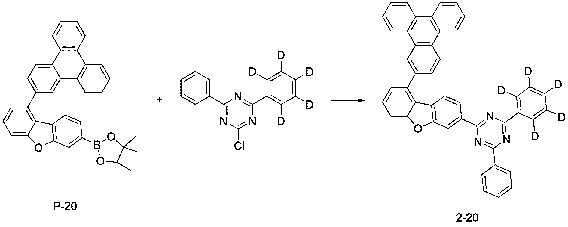
단계7) 화합물 2-20의 합성Step 7) Synthesis of Compound 2-20
질소 분위기에서 P-20(20 g, 38.4 mmol)와 2-클로로-4-페닐-6-(페닐-d5)-1,3,5-트리아진(10.5 g, 38.4 mmol)를 테트라하이드로퓨란 500 mL에 넣고 교반 및 환류하였다. 이 후 포타슘카보네이트(15.9 g, 115 mmol)를 물 80 mL에 녹여 투입하고 충분히 교반한 후 비스(트리 터셔리-부틸포스핀)팔라듐(0.2 g, 0.4mmol)을 투입하였다. 1시간 반응 후 상온으로 식인 후 유기층과 물층을 분리 후 유기층을 증류하였다. 이를 다시 디클로로벤젠에 녹이고, 물로 2회 세척 후에 유기층을 분리하여, 무수황산마그네슘을 넣고 교반한 후 여과하여 여액을 감압 증류하였다. 농축한 화합물을 디클로로벤젠과 테트라파이드로퓨란 재결정을 통해 고체 화합물 2-20(15.3 g, 63%, MS: [M+H]+ = 631)을 제조하였다.In a nitrogen atmosphere, P-20 (20 g, 38.4 mmol) and 2-chloro-4-phenyl-6- (phenyl-d5)-1,3,5-triazine (10.5 g, 38.4 mmol) were added to tetrahydrofuran 500 Into mL, stirred and refluxed. Thereafter, potassium carbonate (15.9 g, 115 mmol) was dissolved in 80 mL of water, and after sufficiently stirring, bis(tritertiary-butylphosphine)palladium (0.2 g, 0.4 mmol) was added. After 1 hour reaction, the mixture was allowed to cool to room temperature, the organic layer and the water layer were separated, and the organic layer was distilled. This was again dissolved in dichlorobenzene, washed twice with water, and the organic layer was separated, anhydrous magnesium sulfate was added thereto, stirred, filtered, and the filtrate was distilled under reduced pressure. Solid compound 2-20 (15.3 g, 63%, MS: [M+H]+ = 631) was prepared from the concentrated compound through recrystallization of dichlorobenzene and tetrapyrrofuran.
합성예 2-6: 화합물 2-23의 합성Synthesis Example 2-6: Synthesis of Compound 2-23

단계1) 화합물 P-21의 합성Step 1) Synthesis of Compound P-21
합성예 2-1의 단계 1에서 1-브로모-3-플루오로-2-요오드벤젠과 5-클로로-2-메톡시페닐보론산를 1-브로모-2-플루오로-3-아이오도벤젠과 (4-클로로-2-메톡시페닐)보론산 으로 변경하여 사용한 것을 제외하고는, 화합물 2-1의 단계 1의 화합물 P-1의 제조 방법과 동일한 제조 방법으로 화합물 P-21을 제조하였다. (78.7 g, 75%, MS: [M+H]+ = 314))In
단계2) 화합물 P-22의 합성Step 2) Synthesis of Compound P-22
합성예 2-1의 단계 2에서, 화합물 P-1 대신 하기 화합물 P-21을 사용한 것을 제외하고는, 화합물 2-1의 단계 2의 화합물 P-2의 제조방법과 동일한 방법으로 화합물 P-22을 합성하였다(72.9 g, 수율 97%; MS: [M+H]
+=300).In
단계3) 화합물 P-23의 합성Step 3) Synthesis of Compound P-23
합성예 2-1의 단계 3에서, 화합물 P-2 대신 하기 화합물 P-22를 사용한 것을 제외하고는, 화합물 2-1의 단계 3의 화합물 P-3의 제조방법과 동일한 방법으로 화합물 P-23을 합성하였다(57.1 g, 수율 84%; MS: [M+H]
+=280).In
단계4) 화합물 P-24의 합성Step 4) Synthesis of Compound P-24
합성예 2-1의 단계 4에서, 화합물 P-3 대신 하기 화합물 P-23을 사용한 것을 제외하고는, 화합물 2-1의 단계 4의 화합물 P-4의 제조방법과 동일한 방법으로 화합물 P-24를 합성하였다(44.9 g, 수율 90%; MS: [M+H]
+=247).In

단계5) 화합물 P-25의 합성Step 5) Synthesis of Compound P-25
합성예 2-5의 단계 5에서, 화합물 P-18 대신 하기 화합물 P-24를 사용한 것을 제외하고는, 화합물 2-5의 단계 5의 화합물 P-19의 제조방법과 동일한 방법으로 화합물 P-25를 합성하였다(MS: [M+H]
+=429).In
단계6) 화합물 P-26의 합성Step 6) Synthesis of Compound P-26
합성예 2-1의 단계 6에서, 화합물 P-5 대신 하기 화합물 P-25를 사용한 것을 제외하고는, 화합물 2-1의 단계 6의 화합물 P-6의 제조방법과 동일한 방법으로 화합물 P-26을 합성하였다(MS: [M+H]
+=521).In
단계7) 화합물 2-23의 합성Step 7) Synthesis of Compound 2-23

합성예 2-5의 단계 7에서, 화합물 P-20 대신 하기 화합물 P-26을 사용한 것을 제외하고는, 화합물 2-5의 단계 7의 화합물 2-20의 제조방법과 동일한 방법으로 화합물 2-23을 합성하였다(MS: [M+H]
+=631).In
합성예 2-7: 화합물 2-27의 합성Synthesis Example 2-7: Synthesis of Compound 2-27

단계1) 화합물 P-27의 합성Step 1) Synthesis of Compound P-27
1-브로모-3-클로로-2-메톡시벤젠(100.0 g, 451.5 mmol)을 테트라하이드로퓨란(1000 mL)에 녹인 후, -78℃로 온도를 낮추고 2.5 M 터셔리-부틸리튬(t-BuLi)(182.4 mL, 456.0 mmol)을 천천히 적가하였다. 동일 온도에서 1시간 동안 교반한 후 트리아이소프로필보레이트(B(OiPr) 3)(156.3 mL, 677.3 mmol)을 가하고, 상온으로 온도를 서서히 올리면서 3시간 동안 교반하였다. 반응 혼합물에 2 N 염산 수용액(150 mL)을 가하고 1.5시간 동안 상온에서 교반하였다. 생성된 침전물을 거르고 물과 에틸에테르(ethyl ether)로 차례로 씻은 후 진공 건조하였다. 건조 후 클로로포름과 에틸아세테이트로 재결정하고 건조하여 화합물 B-1(84.2 g, 수율 90%; MS: [M+H] +=230)을 제조하였다.After dissolving 1-bromo-3-chloro-2-methoxybenzene (100.0 g, 451.5 mmol) in tetrahydrofuran (1000 mL), lowering the temperature to -78°C and 2.5 M tertiary-butyllithium (t- BuLi) (182.4 mL, 456.0 mmol) was slowly added dropwise. After stirring at the same temperature for 1 hour, triisopropylborate (B(OiPr) 3 ) (156.3 mL, 677.3 mmol) was added, and the mixture was stirred for 3 hours while gradually raising the temperature to room temperature. 2N aqueous hydrochloric acid solution (150 mL) was added to the reaction mixture, followed by stirring at room temperature for 1.5 hours. The resulting precipitate was filtered, washed sequentially with water and ethyl ether, and dried under vacuum. After drying, recrystallization with chloroform and ethyl acetate, and dried to prepare compound B-1 (84.2 g, yield 90%; MS: [M+H] + =230).
단계2) 화합물 P-28의 합성Step 2) Synthesis of Compound P-28
합성예 2-1의 단계 1에서 5-클로로-2-메톡시페닐보론산를 화합물 P-27로 변경하여 사용한 것을 제외하고는, 화합물 2-1의 단계 1의 화합물 P-1의 제조 방법과 동일한 제조 방법으로 화합물 P-28를 제조하였다. (74.6 g, 수율 52%; MS: [M+H]
+=314)The same as the method for preparing compound P-1 in
단계3) 화합물 P-29의 합성Step 3) Synthesis of Compound P-29
합성예 2-1의 단계 2에서, 화합물 P-1 대신 하기 화합물 P-28을 사용한 것을 제외하고는, 화합물 2-1의 단계 2의 화합물 P-2의 제조방법과 동일한 방법으로 화합물 P-29를 합성하였다(60.3 g, 수율 85%; MS: [M+H]
+=300).In
단계4) 화합물 P-30의 합성Step 4) Synthesis of Compound P-30
합성예 2-1의 단계 3에서, 화합물 P-2 대신 하기 화합물 P-29를 사용한 것을 제외하고는, 화합물 2-1의 단계 3의 화합물 P-3의 제조방법과 동일한 방법으로 화합물 P-30을 합성하였다(48.1 g, 수율 85%; MS: [M+H]
+=280).In
단계5) 화합물 P-31의 합성Step 5) Synthesis of Compound P-31
합성예 2-1의 단계 4에서, 화합물 P-3 대신 하기 화합물 P-30을 사용한 것을 제외하고는, 화합물 2-1의 단계 4의 화합물 P-4의 제조방법과 동일한 방법으로 화합물 P-31를 합성하였다(40.1 g, 수율 95%; MS: [M+H]
+=247).In
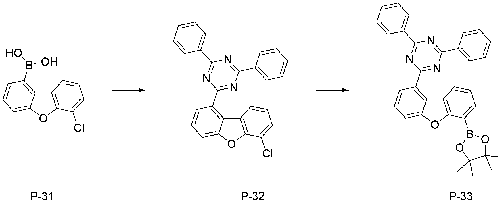
단계6) 화합물 P-32의 합성Step 6) Synthesis of Compound P-32
합성예 2-1의 단계 5에서, 화합물 P-4 대신 하기 화합물 P-31를 사용한 것을 제외하고는, 화합물 2-1의 단계 5의 화합물 P-5의 제조방법과 동일한 방법으로 화합물 P-32를 합성하였다(MS: [M+H]
+=434).In
단계7) 화합물 P-33의 합성Step 7) Synthesis of Compound P-33
합성예 2-1의 단계 6에서, 화합물 P-5 대신 하기 화합물 P-32를 사용한 것을 제외하고는, 화합물 2-1의 단계 6의 화합물 P-6의 제조방법과 동일한 방법으로 화합물 P-33을 합성하였다(MS: [M+H]
+=434).In
단계8) 화합물 2-27의 합성Step 8) Synthesis of Compound 2-27
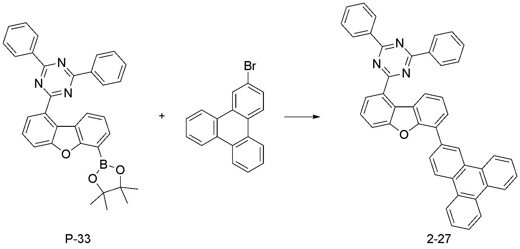
합성예 2-1의 단계 7에서, 화합물 P-6 대신 하기 화합물 P-33을 사용한 것을 제외하고는, 화합물 2-1의 단계 7의 화합물 2-1의 제조방법과 동일한 방법으로 화합물 2-27를 합성하였다(MS: [M+H]
+=626).In
합성예 2-8: 화합물 2-37의 합성Synthesis Example 2-8: Synthesis of Compound 2-37

단계1) 화합물 P-34의 합성Step 1) Synthesis of Compound P-34
합성예 2-1의 단계 1에서 1-브로모-3-플루오로-2-요오드벤젠과 5-클로로-2-메톡시페닐보론산를 1-브로모-3-클로로벤젠과 (2-(메틸싸이오)페닐)보론산으로 변경하여 사용한 것을 제외하고는, 화합물 2-1의 단계 1 의 화합물 P-1의 제조 방법과 동일한 제조 방법으로 화합물 P-34를 제조하였다. (49 g, 수율 79%; MS: [M+H]
+=235)In
단계2) 화합물 P-35의 합성Step 2) Synthesis of Compound P-35
질소 분위기에서 화합물 P-34(49.0 g, 148.5 mmol)에 아세트산(420 mL)을 넣고 브로민(13.9 mL, 271 mmol)을 투입하고 65℃에서 3시간 동안 교반하였다. 냉각 후에 물을 혼합물에 첨가하고, 침전된 고체를 여과하여 물로 3회 세정하였다. 걸러진 여과물을 아세토니트릴과 톨루엔으로 재결정하여 화합물 P-35(50.3 g, 수율 77%; MS: [M+H] +=314)를 제조하였다.Acetic acid (420 mL) was added to compound P-34 (49.0 g, 148.5 mmol) in a nitrogen atmosphere, bromine (13.9 mL, 271 mmol) was added, and the mixture was stirred at 65° C. for 3 hours. After cooling, water was added to the mixture, and the precipitated solid was filtered and washed three times with water. The filtered filtrate was recrystallized from acetonitrile and toluene to prepare compound P-35 (50.3 g, yield 77%; MS: [M+H] + =314).
단계3) 화합물 P-36의 합성Step 3) Synthesis of Compound P-36
화합물 P-35(50.3 g, 160 mmol)에 아세트산(530 mL)을 넣고 35% 과산화수소(16.4 g)를 넣고 상온에서 5시간 동안 교반하였다. 반응물에 NaOH 수용액을 넣고 20분 동안 교반한 뒤 에틸아세테이트를 넣고 수층을 제거하였다. 무수황산마그네슘으로 건조한 후 감압농축 시키고 테트라하이드로퓨란과 에틸아세테이트 혼합용액을 이용하여 재결정화시킨 후 건조하여 상기 화합물 P-36(43.2 g, 수율 87%, MS: [M+H] +=308)을 제조하였다.Acetic acid (530 mL) was added to compound P-35 (50.3 g, 160 mmol), 35% hydrogen peroxide (16.4 g) was added, and the mixture was stirred at room temperature for 5 hours. NaOH aqueous solution was added to the reaction and stirred for 20 minutes, ethyl acetate was added, and the aqueous layer was removed. After drying over anhydrous magnesium sulfate, concentrated under reduced pressure, recrystallized using a mixed solution of tetrahydrofuran and ethyl acetate, dried, and the compound P-36 (43.2 g, yield 87%, MS: [M+H] + =308) Was prepared.
단계4) 화합물 P-37의 합성Step 4) Synthesis of Compound P-37
화합물 P-36(43.2 g, 160 mmol)을 황산(220 mL)에 넣고 5시간 동안 상온에서 교반하였다. 반응물에 NaOH 수용액을 넣고 30분 동안 교반한 뒤 클로로포름를 넣고 층 분리한 뒤 물로 3번 씻어주었다. 에틸아세테이트를 넣고 수층을 제거하였다. 무수황산마그네슘으로 건조한 후 감압농축 시키고 테트라하이드로퓨란과 에틸아세테이트 혼합용액을 이용하여 재결정화시킨 후 건조하여 상기 화합물 P-37(30.6 g, 수율 74%, MS: [M+H] +=296)를 제조하였다.Compound P-36 (43.2 g, 160 mmol) was added to sulfuric acid (220 mL) and stirred at room temperature for 5 hours. NaOH aqueous solution was added to the reaction mixture, stirred for 30 minutes, chloroform was added, the layers were separated, and then washed three times with water. Ethyl acetate was added and the aqueous layer was removed. After drying over anhydrous magnesium sulfate, concentrated under reduced pressure, recrystallized using a mixed solution of tetrahydrofuran and ethyl acetate, dried, and the compound P-37 (30.6 g, yield 74%, MS: [M+H] + =296) Was prepared.
단계5) 화합물 P-38의 합성Step 5) Synthesis of Compound P-38
합성예 2-1의 단계 4에서, 화합물 P-3 대신 하기 화합물 P-37를 사용한 것을 제외하고는, 화합물 2-1의 단계 4의 화합물 P-4의 제조방법과 동일한 방법으로 화합물 P-38를 합성하였다(20.4 g, 수율 75%; MS: [M+H]
+=263).In
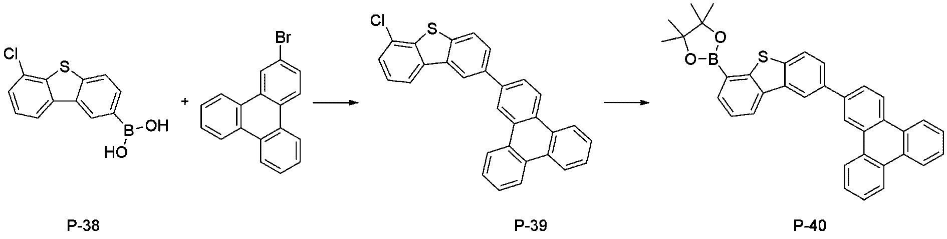
단계6) 화합물 P-39의 합성Step 6) Synthesis of Compound P-39
합성예 2-5의 단계 5에서, 화합물 P-18 대신 하기 화합물 P-38를 사용한 것을 제외하고는, 화합물 2-5의 단계 5의 화합물 P-19의 제조방법과 동일한 방법으로 화합물 P-39를 합성하였다(MS: [M+H]
+=445).In
단계7) 화합물 P-40의 합성Step 7) Synthesis of Compound P-40
합성예 2-1의 단계 6에서, 화합물 P-5 대신 하기 화합물 P-39를 사용한 것을 제외하고는, 화합물 2-1의 단계 6의 화합물 P-6의 제조방법과 동일한 방법으로 화합물 P-40을 합성하였다(MS: [M+H]
+=537).In
단계8) 화합물 2-37의 합성Step 8) Synthesis of compound 2-37
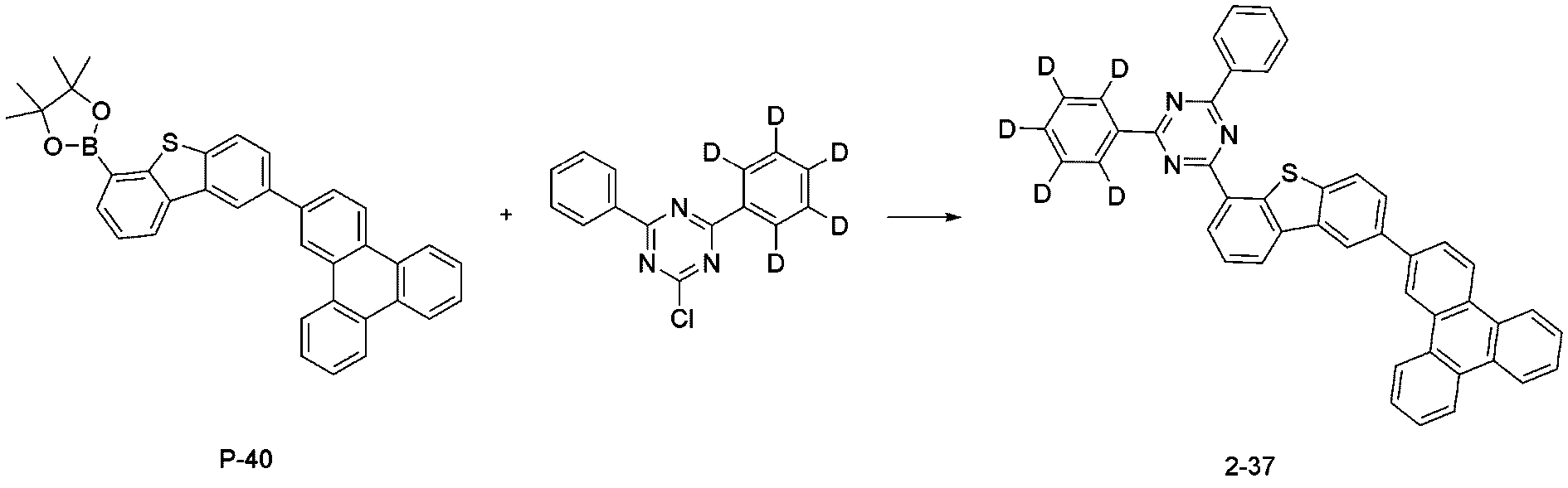
합성예 2-5의 단계 7에서, 화합물 P-20 대신 하기 화합물 P-40을 사용한 것을 제외하고는, 화합물 2-5의 단계 7의 화합물 2-20의 제조방법과 동일한 방법으로 화합물 2-37를 합성하였다(MS: [M+H]
+=647).In
[실시예][Example]
실시예 1Example 1
ITO(indium tin oxide)가 1300 Å의 두께로 박막 코팅된 유리 기판을 세제를 녹인 증류수에 넣고 초음파로 세척하였다. 이때, 세제로는 피셔사(Fischer Co.) 제품을 사용하였으며, 증류수로는 밀리포어사(Millipore Co.) 제품의 필터(Filter)로 2차로 걸러진 증류수를 사용하였다. ITO를 30분간 세척한 후, 증류수로 2회 반복하여 초음파 세척을 10분간 진행하였다. 증류수 세척이 끝난 후, 이소프로필, 아세톤의 용제로 초음파 세척을 하고 건조시킨 후, 상기 기판을 5분간 세정하고 산소 농도 10 ppm 이하, 수분 농도 10 ppm 이하로 유지되는 글로브박스로 기판을 수송시켰다.A glass substrate coated with a thin film of 1300 Å of ITO (indium tin oxide) was placed in distilled water dissolved in a detergent and washed with ultrasonic waves. At this time, a product made by Fischer Co. was used as a detergent, and distilled water secondarily filtered with a filter manufactured by Millipore Co. was used as distilled water. After washing the ITO for 30 minutes, ultrasonic washing was performed for 10 minutes by repeating twice with distilled water. After washing with distilled water, ultrasonic cleaning was performed with a solvent of isopropyl and acetone, followed by drying, the substrate was washed for 5 minutes, and the substrate was transported to a glove box maintained at an oxygen concentration of 10 ppm or less and a moisture concentration of 10 ppm or less.
상기와 같이 준비된 ITO 투명전극 위에, 하기 HTL1 화합물 및 하기 P-dopant를 중량비 100:2로 100 Å 두께로 진공 증착하여 정공주입층을 형성하였다. 그 위에 하기 HTL1 화합물을 1100 Å 두께로 진공 증착하고, HTL2 화합물을 300 Å 두께로 순차로 진공 증착한 다음, 하기 EBL 화합물을 300 Å 두께로 진공 증착하여 정공수송층을 형성하였다. On the ITO transparent electrode prepared as described above, the following HTL1 compound and the following P-dopant were vacuum-deposited at a weight ratio of 100:2 to a thickness of 100 Å to form a hole injection layer. On it, the following HTL1 compound was vacuum-deposited to a thickness of 1100 Å, and the HTL2 compound was sequentially vacuum deposited to a thickness of 300 Å, and then the following EBL compound was vacuum-deposited to a thickness of 300 Å to form a hole transport layer.
상기 정공수송층 위에 앞서 제조한 화합물 1-1, 화합물 2-1, 및 하기 GD 화합물을 중량비 50:50:6으로 350 Å 두께로 진공 증착하여 발광층을 형성하였다. On the hole transport layer, compound 1-1, compound 2-1, and the following GD compound prepared above were vacuum-deposited at a weight ratio of 50:50:6 to a thickness of 350 Å to form a light emitting layer.
상기 발광층 위에 하기 HBL 화합물을 30 Å 두께로 진공 증착하고, 하기 ETL 화합물을 180 Å 두께, 하기 LiQ 화합물을 90 Å 두께로 순차로 진공 증착하여 전자수송층을 형성하였다. 그 위에 LiF 및 Yb을 1:1로 20 Å 두께로 진공 증착하여 전자주입층을 형성하였다. 상기 전자주입층 위에 1000 Å 두께로 알루미늄을 증착하여, 유기발광소자를 제조하였다. 이후, 110 ℃ 오븐에서 40 분간 방치하는 에이징 과정을 거쳐, 최종 유기발광소자를 제조하였다. The following HBL compound was vacuum-deposited on the emission layer to a thickness of 30 Å, the following ETL compound was vacuum-deposited to a thickness of 180 Å, and the LiQ compound was sequentially vacuum-deposited to a thickness of 90 Å to form an electron transport layer. LiF and Yb were vacuum-deposited to a thickness of 20 Å at 1:1 to form an electron injection layer thereon. By depositing aluminum to a thickness of 1000 Å on the electron injection layer, an organic light emitting device was manufactured. Thereafter, the final organic light emitting device was manufactured through an aging process in which it was left in an oven at 110° C. for 40 minutes.
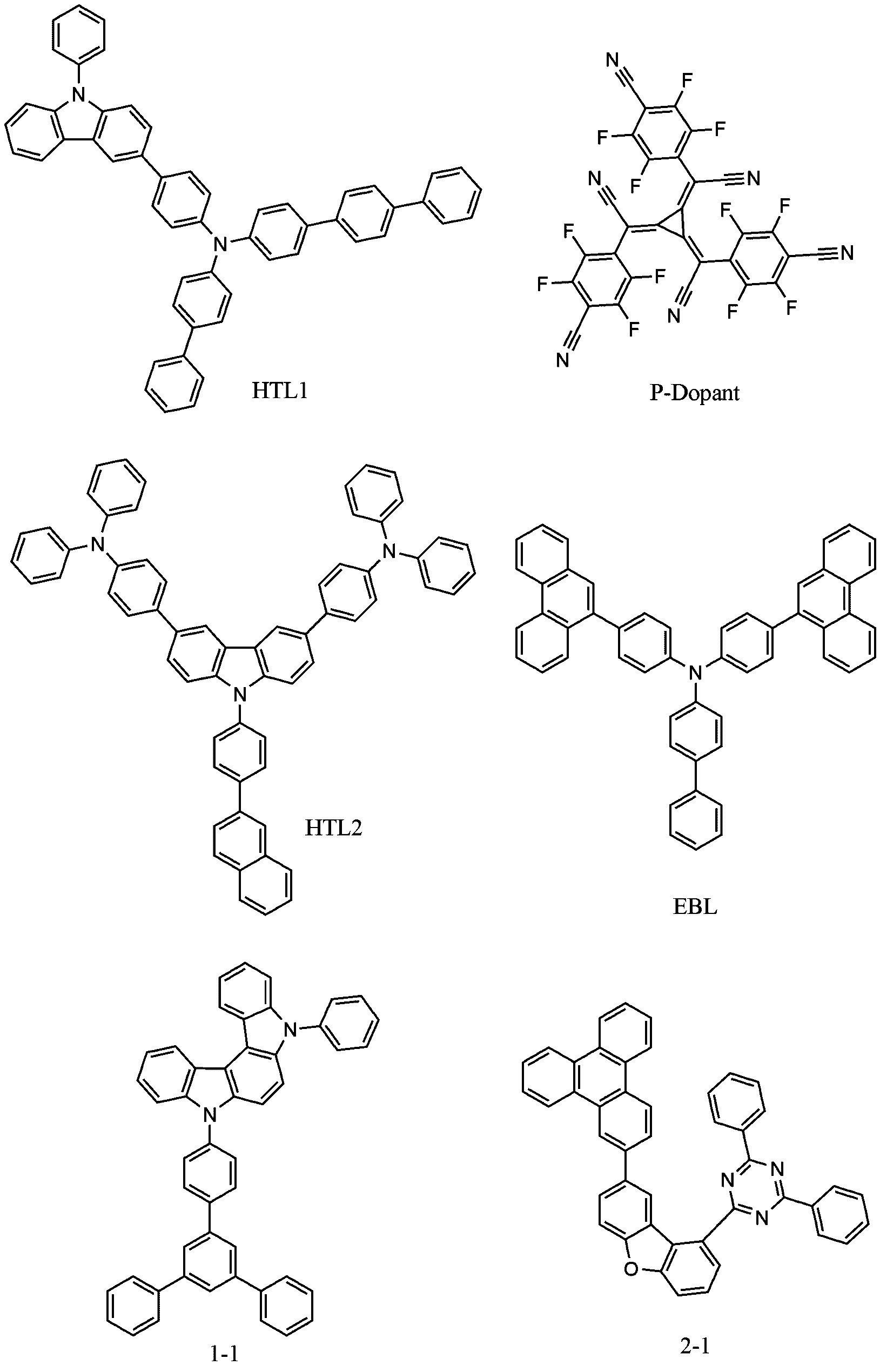
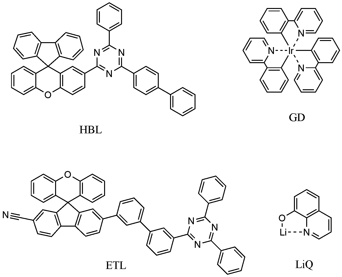
상기의 과정에서 증착은 클러스터 타입의 진공 증착기(Selcos 社)를 사용하였다. 유기물의 증착 속도는 0.4 내지 0.7 Å/sec를 유지하였고, 캐소드의 알루미늄은 2 Å/sec의 증착 속도를 유지하였으며, 증착시 진공도는 1.0 X 10 -7 torr를 유지하였다.In the above process, a cluster type vacuum evaporator (Selcos) was used for deposition. The deposition rate of the organic material was maintained at 0.4 to 0.7 Å/sec, the aluminum of the cathode maintained the deposition rate of 2 Å/sec, and the vacuum degree during deposition was maintained at 1.0 X 10 -7 torr.
실시예 2 내지 17 및 비교예 1 내지 3Examples 2 to 17 and Comparative Examples 1 to 3
상기 실시예 1에서, 발광층의 호스트 화합물로 화합물 1-1 및 2-1 대신 하기 표 1에 기재된 화합물을 사용한 것을 제외하고, 상기 실시예 1과 동일한 방법으로 유기발광소자를 제조하였다. 하기 표에서 P-Host 및 N-Host는 다음과 같다. In Example 1, an organic light emitting device was manufactured in the same manner as in Example 1, except that the compounds shown in Table 1 below were used instead of compounds 1-1 and 2-1 as host compounds of the emission layer. In the table below, P-Host and N-Host are as follows.

상기 실시예 및 비교예에서 제조한 유기 발광 소자에 10 mA/cm 2의 전류를 인가하였을 때의 구동전압(V), 전류효율(cd), 전력효율(lm), 색좌표(CIE) 및 수명(LT97)을 측정하고, 20 mA/cm 2의 전류를 인가하였을 때의 및 수명(LT97)을 측정하여 그 결과를 하기 표 1에 나타내었다. LT97은 20 mA/cm 2의 전류 밀도에서 휘도가 초기 휘도(1600 nit)에서 97%로 감소되는데 소요되는 시간을 의미한다.Examples and Comparative a driving voltage (V), current efficiency (cd), the power efficiency (lm), the color coordinate (CIE) and the lifetime at the time when applying a current of 10 mA / cm 2, the organic light emitting device prepared in Example ( LT97) was measured, and the lifetime (LT97) when a current of 20 mA/cm 2 was applied was measured, and the results are shown in Table 1 below. LT97 refers to the time it takes for the luminance to decrease from the initial luminance (1600 nit) to 97% at a current density of 20 mA/cm 2.
IVL 계측기로는 Photo Research社 PR-670(Power source는 2635B(Keithley 社))을 사용하였으며, 수명 측정은 McScience 社의 M6000을 사용하였다.Photo Research's PR-670 (Power source: 2635B (Keithley's)) was used as the IVL measuring instrument, and McScience's M6000 was used for life measurement.
(hr)LT97
(hr)
상기 표 1에서 보는 바와 같이, 본 발명의 화학식 1의 화합물 및 화학식 2의 화합물을 발광층에 포함하는 유기발광소자는 비교예의 유기발광소자보다 구동전압이 낮고, 고효율 및 장수명 특성을 나타냄을 확인할 수 있다.As shown in Table 1, it can be seen that the organic light-emitting device including the compound of
[부호의 설명][Explanation of code]
1: 기판 2: 양극1: substrate 2: anode
3: 정공수송층 4: 발광층3: hole transport layer 4: light emitting layer
5: 전자수송층 6: 음극5: electron transport layer 6: cathode
7: 정공주입층 8: 전자주입층7: hole injection layer 8: electron injection layer
Claims (10)
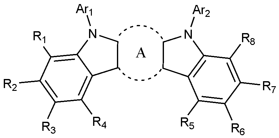

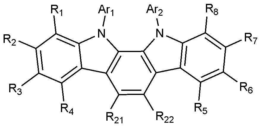
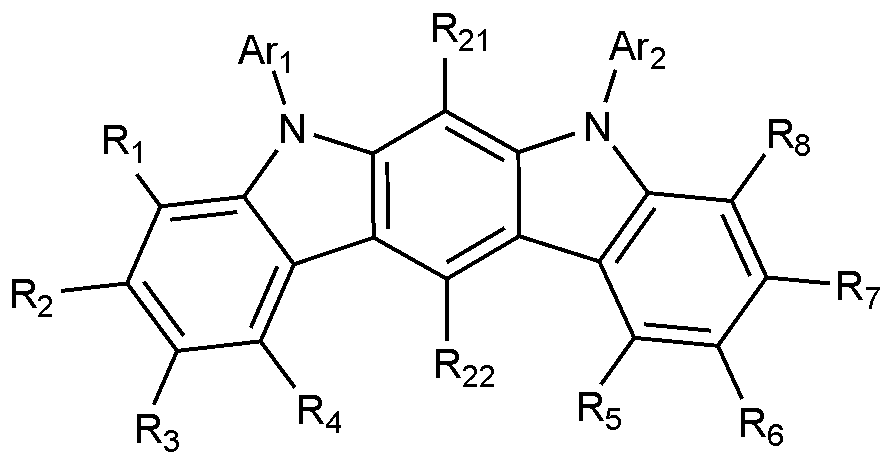


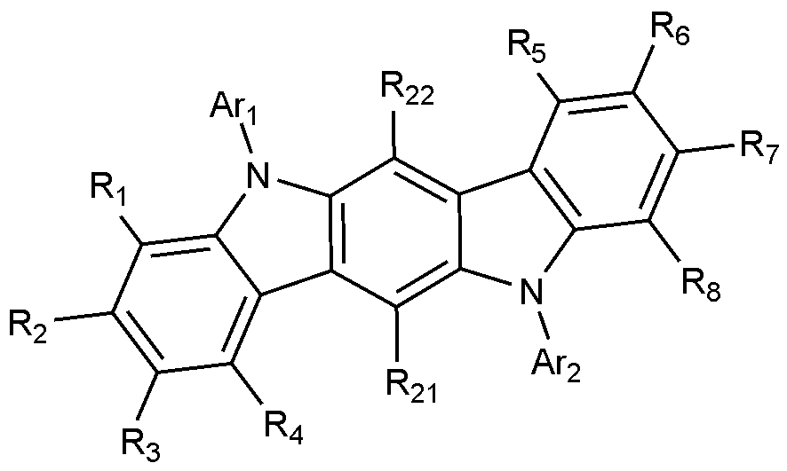


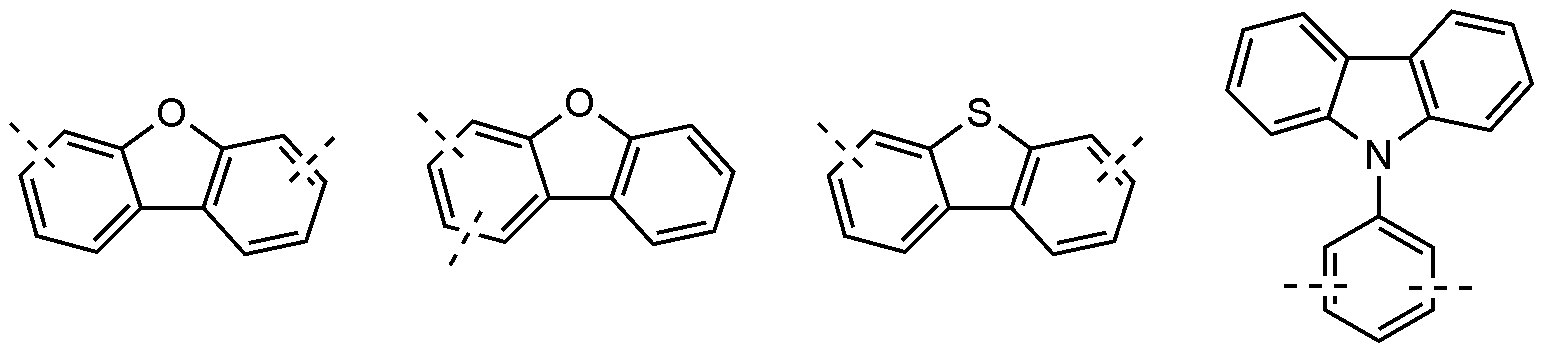
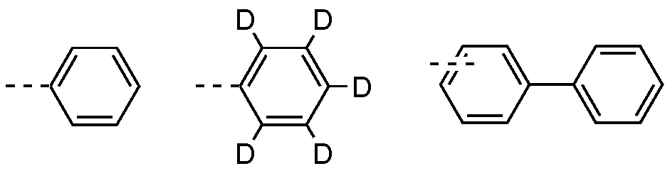


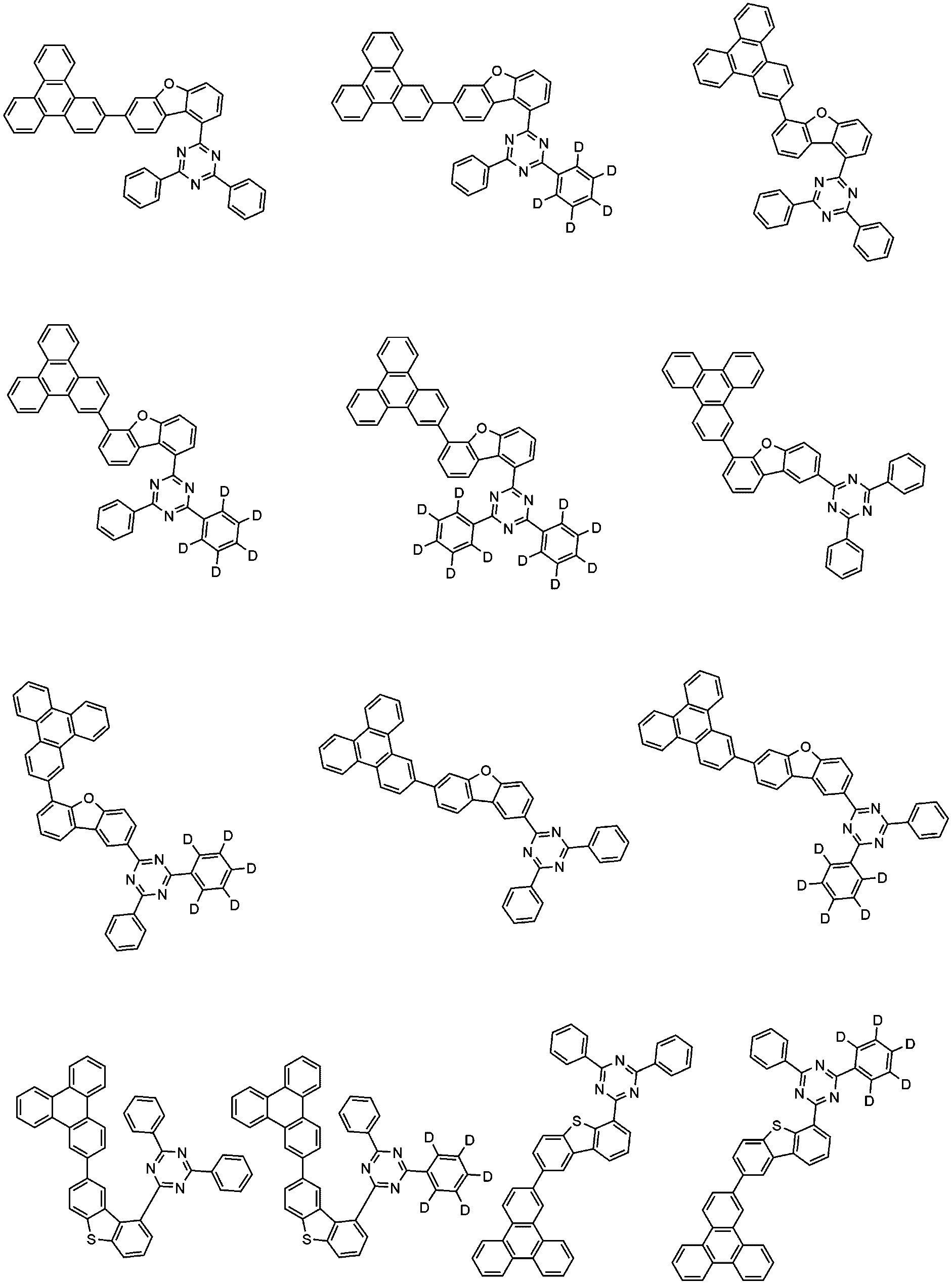
Priority Applications (2)
| Application Number | Priority Date | Filing Date | Title |
|---|---|---|---|
| CN202080043945.5A CN114008810B (en) | 2019-10-18 | 2020-10-16 | Organic light-emitting devices |
| US17/619,682 US12492191B2 (en) | 2019-10-18 | 2020-10-16 | Organic light emitting device |
Applications Claiming Priority (4)
| Application Number | Priority Date | Filing Date | Title |
|---|---|---|---|
| KR10-2019-0129952 | 2019-10-18 | ||
| KR20190129952 | 2019-10-18 | ||
| KR10-2020-0133931 | 2020-10-16 | ||
| KR1020200133931A KR102449062B1 (en) | 2019-10-18 | 2020-10-16 | organic light emitting device |
Publications (1)
| Publication Number | Publication Date |
|---|---|
| WO2021075895A1 true WO2021075895A1 (en) | 2021-04-22 |
Family
ID=75537937
Family Applications (1)
| Application Number | Title | Priority Date | Filing Date |
|---|---|---|---|
| PCT/KR2020/014140 Ceased WO2021075895A1 (en) | 2019-10-18 | 2020-10-16 | Organic light-emitting device |
Country Status (2)
| Country | Link |
|---|---|
| US (1) | US12492191B2 (en) |
| WO (1) | WO2021075895A1 (en) |
Citations (5)
| Publication number | Priority date | Publication date | Assignee | Title |
|---|---|---|---|---|
| KR20170037276A (en) * | 2015-09-25 | 2017-04-04 | 삼성에스디아이 주식회사 | Composition for organic optoelectric device, organic optoelectric device and display device |
| KR20180111558A (en) * | 2017-03-30 | 2018-10-11 | 주식회사 엘지화학 | Organic light emitting device |
| KR20190005522A (en) * | 2017-07-07 | 2019-01-16 | 에스에프씨 주식회사 | organic light-emitting diode with high efficiency, low voltage and long lifetime |
| KR20190081970A (en) * | 2017-12-29 | 2019-07-09 | 삼성에스디아이 주식회사 | Organic compound and composition and organic optoelectronic device and display device |
| CN110272422A (en) * | 2018-03-16 | 2019-09-24 | 北京鼎材科技有限公司 | A kind of general formula compound and its application |
Family Cites Families (8)
| Publication number | Priority date | Publication date | Assignee | Title |
|---|---|---|---|---|
| KR100430549B1 (en) | 1999-01-27 | 2004-05-10 | 주식회사 엘지화학 | New organomattalic complex molecule for the fabrication of organic light emitting diodes |
| DE10135513B4 (en) | 2001-07-20 | 2005-02-24 | Novaled Gmbh | Light-emitting component with organic layers |
| US9040962B2 (en) * | 2010-04-28 | 2015-05-26 | Universal Display Corporation | Depositing premixed materials |
| WO2016108596A2 (en) * | 2014-12-29 | 2016-07-07 | 주식회사 동진쎄미켐 | Novel compound and organic light-emitting device comprising same |
| KR102693420B1 (en) | 2016-05-27 | 2024-08-09 | 삼성전자주식회사 | Organic light emitting device including the same |
| KR102171534B1 (en) | 2017-12-27 | 2020-10-29 | 삼성에스디아이 주식회사 | Composition and organic optoelectronic device and display device |
| KR102207892B1 (en) | 2018-04-10 | 2021-01-26 | 삼성에스디아이 주식회사 | Composition and organic optoelectronic device and display device |
| KR102275039B1 (en) * | 2019-10-08 | 2021-07-08 | 엘티소재주식회사 | Organic light emitting device, manufacturing method of the same and composition for organic layer of organic light emitting device |
-
2020
- 2020-10-16 WO PCT/KR2020/014140 patent/WO2021075895A1/en not_active Ceased
- 2020-10-16 US US17/619,682 patent/US12492191B2/en active Active
Patent Citations (5)
| Publication number | Priority date | Publication date | Assignee | Title |
|---|---|---|---|---|
| KR20170037276A (en) * | 2015-09-25 | 2017-04-04 | 삼성에스디아이 주식회사 | Composition for organic optoelectric device, organic optoelectric device and display device |
| KR20180111558A (en) * | 2017-03-30 | 2018-10-11 | 주식회사 엘지화학 | Organic light emitting device |
| KR20190005522A (en) * | 2017-07-07 | 2019-01-16 | 에스에프씨 주식회사 | organic light-emitting diode with high efficiency, low voltage and long lifetime |
| KR20190081970A (en) * | 2017-12-29 | 2019-07-09 | 삼성에스디아이 주식회사 | Organic compound and composition and organic optoelectronic device and display device |
| CN110272422A (en) * | 2018-03-16 | 2019-09-24 | 北京鼎材科技有限公司 | A kind of general formula compound and its application |
Also Published As
| Publication number | Publication date |
|---|---|
| US12492191B2 (en) | 2025-12-09 |
| US20220389018A1 (en) | 2022-12-08 |
Similar Documents
| Publication | Publication Date | Title |
|---|---|---|
| WO2021025328A9 (en) | Novel compound and organic light emitting device comprising the same | |
| WO2021066623A1 (en) | Organic light emitting device | |
| WO2022031033A1 (en) | Organic light-emitting device | |
| WO2018190666A1 (en) | Heterocyclic compound and organic light-emitting element including same | |
| WO2021125552A1 (en) | Novel compound and organic light-emitting diode comprising same | |
| WO2020256480A1 (en) | Organic light-emitting device | |
| WO2022031036A1 (en) | Organic light emitting device | |
| WO2020262861A1 (en) | Novel compound and organic light emitting device comprising same | |
| WO2021091165A1 (en) | Organic light-emitting device | |
| WO2020235976A1 (en) | Novel compound and organic light emitting device using same | |
| WO2023121096A1 (en) | Novel compound and organic light-emitting device using same | |
| WO2023146319A1 (en) | Organic light-emitting device | |
| WO2023121062A1 (en) | Novel compound and organic light emitting device comprising same | |
| WO2017052221A1 (en) | Novel compound and organic light-emitting element comprising same | |
| WO2022177404A1 (en) | Novel compound, and organic light-emitting device using same | |
| WO2022031020A1 (en) | Novel compound and organic light emitting device comprising same | |
| WO2020091506A1 (en) | Compound and organic light-emitting element comprising same | |
| WO2022250386A1 (en) | Organic light-emitting device | |
| WO2022177401A1 (en) | Novel compound and organic light-emitting device using same | |
| WO2022039518A1 (en) | Novel compound and organic light-emitting device comprising same | |
| WO2021230689A1 (en) | Novel compound and organic light-emitting element comprising same | |
| WO2021230690A1 (en) | Novel compound and organic light-emitting element comprising same | |
| WO2021034156A1 (en) | Novel compound and organic light emitting device using same | |
| WO2020246835A1 (en) | Novel compound and organic light-emitting device using same | |
| WO2020246837A1 (en) | Novel compound and organic light emitting device comprising same |
Legal Events
| Date | Code | Title | Description |
|---|---|---|---|
| 121 | Ep: the epo has been informed by wipo that ep was designated in this application |
Ref document number: 20877492 Country of ref document: EP Kind code of ref document: A1 |
|
| NENP | Non-entry into the national phase |
Ref country code: DE |
|
| 122 | Ep: pct application non-entry in european phase |
Ref document number: 20877492 Country of ref document: EP Kind code of ref document: A1 |