WO2020077958A1 - Conveying of tractor perforating tools in horizontal well - Google Patents
Conveying of tractor perforating tools in horizontal well Download PDFInfo
- Publication number
- WO2020077958A1 WO2020077958A1 PCT/CN2019/080710 CN2019080710W WO2020077958A1 WO 2020077958 A1 WO2020077958 A1 WO 2020077958A1 CN 2019080710 W CN2019080710 W CN 2019080710W WO 2020077958 A1 WO2020077958 A1 WO 2020077958A1
- Authority
- WO
- WIPO (PCT)
- Prior art keywords
- joint
- horizontal well
- flexible
- tractor
- spring
- Prior art date
- Legal status (The legal status is an assumption and is not a legal conclusion. Google has not performed a legal analysis and makes no representation as to the accuracy of the status listed.)
- Ceased
Links
Images


Classifications
-
- E—FIXED CONSTRUCTIONS
- E21—EARTH OR ROCK DRILLING; MINING
- E21B—EARTH OR ROCK DRILLING; OBTAINING OIL, GAS, WATER, SOLUBLE OR MELTABLE MATERIALS OR A SLURRY OF MINERALS FROM WELLS
- E21B43/00—Methods or apparatus for obtaining oil, gas, water, soluble or meltable materials or a slurry of minerals from wells
- E21B43/11—Perforators; Permeators
- E21B43/116—Gun or shaped-charge perforators
-
- E—FIXED CONSTRUCTIONS
- E21—EARTH OR ROCK DRILLING; MINING
- E21B—EARTH OR ROCK DRILLING; OBTAINING OIL, GAS, WATER, SOLUBLE OR MELTABLE MATERIALS OR A SLURRY OF MINERALS FROM WELLS
- E21B17/00—Drilling rods or pipes; Flexible drill strings; Kellies; Drill collars; Sucker rods; Cables; Casings; Tubings
- E21B17/02—Couplings; joints
- E21B17/021—Devices for subsurface connecting or disconnecting by rotation
-
- E—FIXED CONSTRUCTIONS
- E21—EARTH OR ROCK DRILLING; MINING
- E21B—EARTH OR ROCK DRILLING; OBTAINING OIL, GAS, WATER, SOLUBLE OR MELTABLE MATERIALS OR A SLURRY OF MINERALS FROM WELLS
- E21B17/00—Drilling rods or pipes; Flexible drill strings; Kellies; Drill collars; Sucker rods; Cables; Casings; Tubings
- E21B17/02—Couplings; joints
- E21B17/04—Couplings; joints between rod or the like and bit or between rod and rod or the like
- E21B17/06—Releasing-joints, e.g. safety joints
-
- E—FIXED CONSTRUCTIONS
- E21—EARTH OR ROCK DRILLING; MINING
- E21B—EARTH OR ROCK DRILLING; OBTAINING OIL, GAS, WATER, SOLUBLE OR MELTABLE MATERIALS OR A SLURRY OF MINERALS FROM WELLS
- E21B17/00—Drilling rods or pipes; Flexible drill strings; Kellies; Drill collars; Sucker rods; Cables; Casings; Tubings
- E21B17/10—Wear protectors; Centralising devices, e.g. stabilisers
- E21B17/1014—Flexible or expansible centering means, e.g. with pistons pressing against the wall of the well
- E21B17/1021—Flexible or expansible centering means, e.g. with pistons pressing against the wall of the well with articulated arms or arcuate springs
-
- E—FIXED CONSTRUCTIONS
- E21—EARTH OR ROCK DRILLING; MINING
- E21B—EARTH OR ROCK DRILLING; OBTAINING OIL, GAS, WATER, SOLUBLE OR MELTABLE MATERIALS OR A SLURRY OF MINERALS FROM WELLS
- E21B17/00—Drilling rods or pipes; Flexible drill strings; Kellies; Drill collars; Sucker rods; Cables; Casings; Tubings
- E21B17/10—Wear protectors; Centralising devices, e.g. stabilisers
- E21B17/1042—Elastomer protector or centering means
-
- E—FIXED CONSTRUCTIONS
- E21—EARTH OR ROCK DRILLING; MINING
- E21B—EARTH OR ROCK DRILLING; OBTAINING OIL, GAS, WATER, SOLUBLE OR MELTABLE MATERIALS OR A SLURRY OF MINERALS FROM WELLS
- E21B17/00—Drilling rods or pipes; Flexible drill strings; Kellies; Drill collars; Sucker rods; Cables; Casings; Tubings
- E21B17/10—Wear protectors; Centralising devices, e.g. stabilisers
- E21B17/1057—Centralising devices with rollers or with a relatively rotating sleeve
-
- E—FIXED CONSTRUCTIONS
- E21—EARTH OR ROCK DRILLING; MINING
- E21B—EARTH OR ROCK DRILLING; OBTAINING OIL, GAS, WATER, SOLUBLE OR MELTABLE MATERIALS OR A SLURRY OF MINERALS FROM WELLS
- E21B23/00—Apparatus for displacing, setting, locking, releasing or removing tools, packers or the like in boreholes or wells
- E21B23/14—Apparatus for displacing, setting, locking, releasing or removing tools, packers or the like in boreholes or wells for displacing a cable or a cable-operated tool, e.g. for logging or perforating operations in deviated wells
-
- E—FIXED CONSTRUCTIONS
- E21—EARTH OR ROCK DRILLING; MINING
- E21B—EARTH OR ROCK DRILLING; OBTAINING OIL, GAS, WATER, SOLUBLE OR MELTABLE MATERIALS OR A SLURRY OF MINERALS FROM WELLS
- E21B43/00—Methods or apparatus for obtaining oil, gas, water, soluble or meltable materials or a slurry of minerals from wells
- E21B43/11—Perforators; Permeators
- E21B43/119—Details, e.g. for locating perforating place or direction
-
- E—FIXED CONSTRUCTIONS
- E21—EARTH OR ROCK DRILLING; MINING
- E21B—EARTH OR ROCK DRILLING; OBTAINING OIL, GAS, WATER, SOLUBLE OR MELTABLE MATERIALS OR A SLURRY OF MINERALS FROM WELLS
- E21B47/00—Survey of boreholes or wells
- E21B47/09—Locating or determining the position of objects in boreholes or wells, e.g. the position of an extending arm; Identifying the free or blocked portions of pipes
- E21B47/092—Locating or determining the position of objects in boreholes or wells, e.g. the position of an extending arm; Identifying the free or blocked portions of pipes by detecting magnetic anomalies
Definitions
- the invention belongs to the technical field of perforating in petroleum engineering, and is especially a perforating tool of a horizontal well conveying tractor suitable for perforating operations of horizontal wells.
- the hydraulic transmission cable perforation uses a pump truck to drive fluid to drive the perforation tool string to move at the bottom of the well.
- the continuous tubing conveys the perforation and the flexible pipe directly conveys the perforating tool string.
- the cost of hydraulic conveying is low, but hydraulic conveying must provide a hydraulic channel for the operation, and the first-stage perforation and bridge plug seat sealing can not be achieved.
- the high-angle tilting well cannot control the decline of the perforating equipment, resulting in cable damage and serious There will also be accidents of perforating equipment falling into the well.
- CN204476303 discloses a drilling tool assembly, which is connected with a shock absorber and a centralizer in order from the bottom to the top between the screw rod and the drill rod.
- the combination of drilling tools makes the PDC bit suitable for drilling in formations containing gravel, uneven transfer, large changes in softness and hardness, and prolongs the service life of the PDC bit.
- the purpose of the present invention is to aim at the above-mentioned technical status, aiming to provide a perforating operation that can be adapted to the first-stage perforation, repairing holes after sealing of bridge plug seats, perforation of large vertical horizontal wells, etc .;
- a perforation tool for horizontal well transport tractors that effectively reduces construction time, reduces work intensity, and significantly improves the perforation efficiency of horizontal wells.
- the purpose of the present invention is achieved by the horizontal well conveying tractor perforating tool, lost joint, rotating joint, upper centralizer, brake sub-joint, magnetic positioning sub-joint, tractor, lower centralizer, flexible sub-joint, safety
- the power supply short section, shock absorber, perforator and ball gun tail are connected as a whole from the top to the bottom by threaded screw; the cable horse faucet is connected to the lost short section;
- the lost joint consists of upper and lower joint assemblies; the upper joint of the upper joint assembly is screwed to the cable faucet, the lower joint of the upper joint assembly is screwed to the outer tube, and the connecting sleeve located in the outer tube passes through the guide key It is connected with the upper joint, and the connecting sleeve has a locking groove; the lower joint assembly has a locking claw that locks the locking groove of the upper joint assembly, and the locking claw is fixed on the lower joint two by a screw pin; the locking claws are evenly distributed in the salvage Between the head and the lower joint;
- the rotating shaft of the centralizer passes through the inner holes of the upper and lower spring sleeves, and both ends of the rotating shaft are connected to the centralizing upper and lower joints of the centralizer; the spring sleeve can move on the rotating shaft, and the spring sleeve and the rotating shaft There is a spring in between, the compression cap and the spring sleeve press the spring through the thread, and the push rod is placed on the top of the spring sleeve; there are four sets of centralizing arms between the upper and lower spring sleeves; One end of the brace arm is fixed on the push rod by a steel pin, and one end is mounted on the bearing; the bearing is installed between the two brace arms and is fixed by the steel pin;
- the brake control mechanism is screwed between the upper brake joint and the lower brake joint of the brake nipple; the brake claw of the brake control mechanism is located in the middle of one end of the two support arms, and is connected and fixed by a steel pin, and the other end of the two support arms passes through the steel pin It is fixed on the pushing block, a spring is installed between the pushing block and the pushing rod, and the pushing rod is connected with the motor assembly.
- the invention is used in the perforation construction of horizontal wells.
- the centralizer can always keep the tractor in the center state to ensure the stable operation of the tractor;
- the brake stub can provide the required resistance to prevent the tractor perforating tool combination from sliding down on the horizontal well, and damage the cable or the tractor's perforating tool combination.
- the flexible stub can change the rigidity of the tractor perforating tool combination to ensure the delivery of the tractor perforating tool combination; when the tractor fails, the working high-voltage power supply of the tractor will be connected to the lower end, and the safe power supply is short and energy saving Preventing the high-voltage power of the tractor from communicating with the perforator guarantees the electricity safety of the perforator and prevents accidental perforation accidents of the perforator.
- the invention overcomes the failure of the first-stage perforation and bridge plug seat refilling operation in the hydraulic conveying method, the falling accident caused by the perforating equipment sliding down, and the perforating engineering quality accident and large perforation on the casing coupling in the coiled tubing conveying method
- the shortcomings of the horizontal vertical wells are inoperable, high working intensity, long time and high safety risk. It can be adapted to work under various working conditions such as the first-stage perforation, the hole filling after the bridge plug seat is sealed, and the perforation of the horizontal well with large vertical ratio; the invention can effectively reduce the construction time, reduce the working intensity, and significantly improve the horizontal well shooting Hole benefits.
- Figure 1 is a schematic diagram of the structure of the present invention
- Figure 2 is an outline drawing of the present invention
- Figure 3 is a schematic diagram of the structure of the upper joint assembly of the missing short section
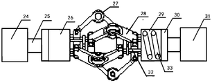
- Figure 5 is a schematic diagram of the centralizer structure
- Figure 6 is a schematic diagram of the brake short joint structure
- Figure 7 is a schematic diagram of the tractor structure
- Figure 8 is a schematic diagram of the structure of the flexible short section
- Figure 9 is a schematic diagram of the shock absorber structure
- 10 is a schematic diagram of the structure of the ball gun tail.
- the lost joint 1 of the present invention the rotating joint 2, the upper centralizer 3, the brake sub-section 4, the magnetic positioning sub-section 5, the tractor 6, the lower centralizer 7, the flexible sub-section 8, safety
- the power supply nipple 9, the shock absorber 10, the perforator 11 and the ball gun tail 12 are connected in an integrated manner from the top to the bottom by means of threaded screws.
- the cable bridle is easily and quickly connected to the lost nipple through threaded screws.
- the lost joint 1 is composed of upper and lower joint components.
- the upper connector 17 of the upper connector assembly is screwed to the cable faucet, the lower connector of the upper connector assembly is screwed to the outer tube 21, and the connecting sleeve 19 located in the outer tube is connected to the upper connector through the guide key 18. ⁇ ⁇ 20 ⁇ Locking slot 20.
- the lower joint assembly has a locking pawl 15 that locks the locking groove of the upper joint assembly, and the locking pawl is fixed on the lower joint two by a screw pin 16.
- the locking claws are evenly distributed between the salvage head and the lower joint;
- the invention has three locking claws, and the three locking claws are evenly distributed between the salvage head 13 and the lower joint two 14 at an included angle of 120 °.
- the salvage head 13 of the lower joint assembly is inserted into the outer tube 21 of the upper joint assembly, the connecting sleeve 19 is inserted into the salvage head, the locking claw 15 is locked into the locking groove 20, and the three locking claws 15 are held tightly In the locking groove 20, the salvage head and the locking claw are integrated into one body, and can withstand a pulling force of 10,000 Newtons without being slipped off.
- the locking claw When the present invention encounters a card in the well, after the release command is issued through the ground, the locking claw will disengage from the locking groove, the upper joint assembly slips off from the lower joint assembly, the upper joint assembly is pulled out of the wellhead through the cable, and the lower joint assembly remains On the tractor perforating tool.
- the invention can be taken out of the wellhead by connecting the matching fishing tool to the fishing head of the lower joint assembly.
- the rotary joint 2 of the present invention adopts a rotary joint provided with a pressure balance mechanism disclosed in CN105507879. It consists of an upper joint, a rotating component, a central shaft and a lower joint.
- the rotating component is connected to the upper joint through a thread.
- the rotating component has a 360 ° arbitrary rotating component.
- the central shaft is connected to the rotating component inside the rotating component through a connecting sleeve.
- the central shaft is connected to the lower joint through the thread, so that the upper joint and the lower joint
- the joints are relatively free to rotate.
- the upper joint of the rotating nipple is connected to the missing nipple by threads.
- the cable will produce a rotating torque.
- the upper connector rotates in the direction of the cable torque, and the other components connected to the lower connector remain in their original state, thereby releasing the cable's rotating torque and ensuring that the cable is not damaged during the downhole process.
- the upper centralizer 3 and the lower centralizer 7 of the present invention have the same structure.
- the rotation shaft 25 of the centralizer passes through the inner holes of the upper spring sleeve 26 and the lower spring sleeve 29, and both ends of the centralizer upper joint 24 and centralizer lower joint 31 of the centralizer are rotated at both ends.
- the spring sleeve can move on the rotating shaft.
- a spring 33 is installed between the spring sleeve and the rotating shaft.
- the compression cap 30 and the spring sleeve compress the spring through threads, and the push rod 32 is placed on the top of the spring sleeve.
- One end of the supporting arm 28 of each set of centralizing arm is fixed on the push rod 32 through a steel pin, and one end is mounted on a bearing 27.
- the bearing is mounted between the two supporting arms and fixed by a steel pin.
- the four sets of centralizing arms of the centralizer are evenly distributed on the rotating shaft at 90 °.
- the opening size of the centralizing arm can be adjusted by a spring sleeve compression spring.
- the supporting force is 50kg ⁇ 2kg, which can ensure that the invention is centered in the horizontal well and reduces the friction To improve the carrying capacity of the tractor.
- the upper brake joint of the brake spool 4 of the present invention is connected to the upper centralizer 3 through threads.
- the brake control mechanism 42 is screwed between the upper brake joint 41 and the lower brake joint 43.
- the brake claw 40 of the brake control mechanism is located in the middle of one end of the two support arms 37 and is connected and fixed by a steel pin 38. The other end of the two support arms is fixed to the push block 39 by a steel pin.
- Motor components are commonly used motor components.
- the motor assembly 34 drives the push rod 35 to move laterally, and the compression spring 36 pushes the push block 39 to move, which drives the brake pawl to expand upwards.
- the length of the extension determines the friction of the brake pawl on the well wall.
- the size and the maximum friction force are not less than 400kg, which can ensure the static state or uniform speed movement required for the operation of the tractor perforating tool.
- the motor assembly drives the push rod to move laterally in the opposite direction, the spring returns, and the support arm drives the brake claws to move downwards. Finally, the brake claws are gathered in the brake short section.
- the friction resistance generated by the brake short joint can enable the present invention to be in a static state at the perforation position or in a state of uniform speed movement through the upturned section of the horizontal well, thereby preventing the occurrence of accidents.
- the magnetic positioning spool 5 of the present invention adopts the existing magnetic positioning spool, which is composed of a magnetic positioning upper joint, a probe part and a magnetic positioning lower joint.
- the upper connector of the magnetic positioning is connected with the brake stub through threads.
- the probe part is fixed on both ends of the coil winding by a set of coils wound on a soft iron core and two permanent magnetic steels in the same polarity manner.
- the magnetic positioning stub passes through the downhole casing coupling, the magnetic flux of the permanent magnetic steel of the probe part changes, and the magnetic force line through the coil changes accordingly.
- An induced electromotive force can be obtained on the coil, and the induced electromotive force can determine the perforator's position.
- the tractor 6 of the present invention is composed of a hydraulic control system 49, a push hydraulic system 50 and a plurality of traction sections 51; the hydraulic control system is to pressurize the hydraulic oil in the push hydraulic system and deliver it to the hydraulic cylinder 58 control device.
- the main thrust arm 52 of each traction section is fixed on the traction section 51 by a steel pin, and the other end is connected to the driving wheel 54.
- the auxiliary push arm 53 is connected to the main push arm by a steel pin, and the other end is connected to a push rod 55.
- the main push arm can be opened or folded through the push rod.
- the push rod extends into the hydraulic cylinder, and there is a seal ring 56 between the push rod and the traction section.
- the seal ring isolates the hydraulic cylinder 58 from the liquid in the horizontal well and prevents the liquid from entering the hydraulic cylinder.
- a spring 57 is installed on the push rod. When the hydraulic cylinder is under low pressure, the spring can be automatically retracted by the spring return.
- the push rod 55 moves forward, compressing the spring 57 and at the same time drives the auxiliary push arm 53 to move forward, the auxiliary arm drives the main push The arm moves upward, and the main push arm opens, bringing the drive wheel into close contact with the horizontal well wall and applying pressure to the horizontal well wall.
- the pressure depends on the pressure of the hydraulic oil in the hydraulic cylinder.
- the spring automatically resets and pushes the push rod to move backward, and at the same time drives the auxiliary push arm to move backward, the auxiliary push arm
- the main push arm is driven to move down, the main push arm is gathered into the traction section, and the tractor stops working.
- the flexible core assembly of the flexible stub 8 of the present invention is fixed between the flexible upper joint 62 and the flexible lower joint 59 by four screws 60, and the flexible upper joint and the centralizing lower joint of the lower centralizer are connected by a threaded buckle.
- the flexible core assembly has multiple flexible sections on the wall of the short section tube, and each flexible section has multiple T-shaped cuts connected in positive and negative directions, and the portions between the cuts form flexible flower blocks.
- the flexible piece of each flexible section can be moved or rotated within the range of the incision, so that the flexible short section can be bent in any direction in the space, the bending angle is less than 10 °, and it can withstand a tensile pressure of 45000kg.
- Flexible short-term energy saving makes the invention move freely in the horizontal section of the horizontal well.
- the invention is to cut five flexible sections with laser on the wall of the short section pipe, each flexible section has four T-shaped cuts connected in positive and negative directions, and the cut 61 width is 2mm ⁇ 1mm.
- the safety power supply section 9 of the present invention adopts the "Safety Power Conversion Unit for Underground Cable Tractor Conveying Perforation" published by CN207245653, which is controlled by a cable driving circuit, a signal receiving circuit, a data encoding and decoding circuit, a mechanical switch control circuit, and an electronic switch Circuit and power circuit composition.
- the mechanical switch control circuit connected at both ends of the electronic switch control circuit taps the tractor and perforating equipment.
- the electronic switch control circuit is connected to the power supply circuit and the mechanical switch control circuit, the signal receiving circuit and the cable drive circuit of the mechanical switch control circuit are connected to the data coding and decoding circuit, and the single chip computer; the single chip computer is connected to the motor.
- the mechanical switch includes a control unit, a motor, a moving contact, a switch contact and a spring.
- the switch contact always keeps the mechanical switch in the off state under the action of the spring.
- the instrument barrel is connected to the upper joint and the lower joint by threads, and the mechanical switch is installed in the instrument barrel.
- the upper joint and the flexible stub are connected by threads.
- the control unit controls the motor to move the moving contact in a counterclockwise direction.
- the moving contact When the moving contact is turned down, it will squeeze the switch contact downward, closing the mechanical switch and providing a perforator Power supply path.
- the mechanical switch When the mechanical switch is disconnected, the moving contact continues to move in a counterclockwise direction.
- the static contact When the moving contact is separated from the static contact, the static contact will disconnect the mechanical switch under the spring reset action to prevent the tractor from working The working high-voltage power supply of the tractor enters the perforator, causing damage to the perforator or accidental perforation.
- the sliding sleeve 72 of the shock absorber 10 of the present invention is connected to the upper damping joint 70 at one end, and the end of one end is snapped into the lower damping joint 73, the spring 71 is outside the sliding sleeve, and the lower joint of the damping has a block Circle 74.
- the distance between the end of the sliding sleeve and the retaining ring, that is, the moving distance of the end 72 of the sliding sleeve in the lower joint is greater than the maximum compression length of the spring.
- the perforator 11 of the present invention uses a commonly used perforator.
- the bullet frame body of the perforator is welded between the upper positioning ring and the lower positioning ring.
- the projectile body is a hollow cylindrical steel body, and the projectile holes of the same diameter are spirally arranged on the surface at an angle of 60 °.
- the two ends of the projectile body are provided with an ejector screw hole, and the projectile body is fixed to the perforating gun through the ejector wire.
- the perforating bomb When the perforating operation of the horizontal well transporting tractor is installed, the perforating bomb is installed in the bullet hole. After the tractor transporting the perforator reaches a predetermined position, the perforating bomb ignites and explodes, opening the formation to let the fluid in the formation below the horizontal well into the horizontal well .
- one end of the tail body 22 of the ball gun tail 12 of the present invention is screwed to the perforator, and the other end is a conical body.
- Six semicircular grooves are evenly distributed on the outer circumferential surface of the gun tail, and two thirds of the balls 23 are located in the semicircular grooves.
- the semi-circular groove is reduced to a position where the ball does not fall off on the gun body and can be rotated arbitrarily, changing the moving friction state of the perforator from sliding friction to rolling friction, reducing the perforator Frictional resistance of transportation.
- the invention is adopted in the perforation construction of horizontal wells.
- the centralizer can always keep the tractor in the center state to ensure the stability of the tractor;
- the brake stub can provide the required resistance to prevent the present invention from sliding down on the upturned section of the horizontal well, damage the cable or the tractor's perforation tool combination, and the accident of the well falling; encountering small curvature water
- the flexible short section can change the rigidity of the present invention to ensure the delivery of the tractor perforating tool combination; when the tractor fails, the working high-voltage power supply of the tractor will be connected to the lower end. Communicating with the perforator ensures the electricity safety of the perforator and prevents accidental perforation accidents.
Landscapes
- Engineering & Computer Science (AREA)
- Life Sciences & Earth Sciences (AREA)
- Geology (AREA)
- Mining & Mineral Resources (AREA)
- Physics & Mathematics (AREA)
- Environmental & Geological Engineering (AREA)
- Fluid Mechanics (AREA)
- General Life Sciences & Earth Sciences (AREA)
- Geochemistry & Mineralogy (AREA)
- Mechanical Engineering (AREA)
- Geophysics (AREA)
- Earth Drilling (AREA)
Abstract
Description
本发明属于石油工程射孔技术领域,尤其是适用于水平井射孔作业的水平井输送牵引器射孔工具。The invention belongs to the technical field of perforating in petroleum engineering, and is especially a perforating tool of a horizontal well conveying tractor suitable for perforating operations of horizontal wells.
现有石油工程水平井射孔施工中,一般采用水力输送电缆射孔和连续油管输送射孔两种方式,其中水力输送电缆射孔采用泵车驱动流体而带动射孔工具串在井底移动,连续油管输送射孔以挠性管直接输送射孔工具串。水力输送成本低,但是水力输送必须为作业提供水力通道,无法实现首段射孔和桥塞座封后补孔作业,另外在大角度上翘井无法控制射孔设备下滑,造成电缆损坏,严重时还会产生射孔设备掉井事故。连续油管输送成功率高,但是连续油管输送无法避免油管在水平井中出现螺旋弯曲,深度测量精度无法控制,造成在套管接箍上射孔等工程质量事故;在大位垂比水平井中连续油管会出现自锁,无法继续进行作业;设备大而重,不仅安装、拆卸工作强度大、时间长、安全风险高,并且运输道路要求高。In the perforation construction of existing horizontal wells in petroleum engineering, two methods of hydraulic transmission cable perforation and coiled tubing perforation are generally used. The hydraulic transmission cable perforation uses a pump truck to drive fluid to drive the perforation tool string to move at the bottom of the well. The continuous tubing conveys the perforation and the flexible pipe directly conveys the perforating tool string. The cost of hydraulic conveying is low, but hydraulic conveying must provide a hydraulic channel for the operation, and the first-stage perforation and bridge plug seat sealing can not be achieved. In addition, the high-angle tilting well cannot control the decline of the perforating equipment, resulting in cable damage and serious There will also be accidents of perforating equipment falling into the well. The success rate of coiled tubing transportation is high, but coiled tubing transportation cannot avoid the spiral bending of tubing in horizontal wells, and the depth measurement accuracy cannot be controlled, resulting in engineering quality accidents such as perforation on casing couplings; coiled tubing in large horizontal wells There will be self-locking, and the operation cannot be continued; the equipment is large and heavy, not only the installation and disassembly work is intensive, the time is long, the safety risk is high, and the transportation road requirements are high.
CN204476303公开了一种钻具组合,其在螺杆与钻杆之间自下而上依次连接有减震器和扶正器。该钻具组合使PDC钻头适应于含有砾石、交接不均质、软硬变化大等地层中的钻井施工,延长PDC钻头使用寿命。CN204476303 discloses a drilling tool assembly, which is connected with a shock absorber and a centralizer in order from the bottom to the top between the screw rod and the drill rod. The combination of drilling tools makes the PDC bit suitable for drilling in formations containing gravel, uneven transfer, large changes in softness and hardness, and prolongs the service life of the PDC bit.
发明内容Summary of the invention
本发明的目的是针对上述技术现状,旨在提供一种可适应于首段射孔,桥塞座封后补孔,大位垂比水平井射孔等各种工况下射孔作业;可有效减少施工时间,降低工作强度,明显提高水平井射孔效益的水平井输送牵引器射孔工具。The purpose of the present invention is to aim at the above-mentioned technical status, aiming to provide a perforating operation that can be adapted to the first-stage perforation, repairing holes after sealing of bridge plug seats, perforation of large vertical horizontal wells, etc .; A perforation tool for horizontal well transport tractors that effectively reduces construction time, reduces work intensity, and significantly improves the perforation efficiency of horizontal wells.
本发明目的的实现方式为,水平井输送牵引器射孔工具,丢手短节、旋转短节、上扶正器、刹车短节、磁定位短节、牵引器、下扶正器、柔性短节、安全供电短节、减震器、射孔器和滚珠枪尾从上至下依次通过螺纹丝扣方式连为一体;电缆马龙头与丢手短节连接;The purpose of the present invention is achieved by the horizontal well conveying tractor perforating tool, lost joint, rotating joint, upper centralizer, brake sub-joint, magnetic positioning sub-joint, tractor, lower centralizer, flexible sub-joint, safety The power supply short section, shock absorber, perforator and ball gun tail are connected as a whole from the top to the bottom by threaded screw; the cable horse faucet is connected to the lost short section;
所述丢手短节由上、下接头组件组成;所述上接头组件的上接头与电缆马龙头螺接,上接头组件的下接头一与外管螺接,位于外管内的连接套通过导向键与上接头连接,连接套上有锁紧槽;所述下接头组件有锁紧上接头组件锁紧槽的锁定爪,锁定爪通过螺销固定在下接头二上;所述锁定爪均匀分布在打捞头与下接头之间;The lost joint consists of upper and lower joint assemblies; the upper joint of the upper joint assembly is screwed to the cable faucet, the lower joint of the upper joint assembly is screwed to the outer tube, and the connecting sleeve located in the outer tube passes through the guide key It is connected with the upper joint, and the connecting sleeve has a locking groove; the lower joint assembly has a locking claw that locks the locking groove of the upper joint assembly, and the locking claw is fixed on the lower joint two by a screw pin; the locking claws are evenly distributed in the salvage Between the head and the lower joint;
所述扶正器的旋转轴从上、下弹簧套筒内部孔中穿过,旋转轴两端接扶正器的扶正上、下接头;弹簧套筒能在旋转轴上移动,弹簧套筒与旋转轴之间安有弹簧,压紧帽与弹簧套筒通过螺纹压紧弹簧,将推杆置于弹簧套筒顶部;上、下弹簧套筒之间有四组扶正臂;所述每组扶正臂的撑臂一端通过钢销固定在推杆上,一端装在轴承上;轴承装在两撑臂之间,通过钢销固定;The rotating shaft of the centralizer passes through the inner holes of the upper and lower spring sleeves, and both ends of the rotating shaft are connected to the centralizing upper and lower joints of the centralizer; the spring sleeve can move on the rotating shaft, and the spring sleeve and the rotating shaft There is a spring in between, the compression cap and the spring sleeve press the spring through the thread, and the push rod is placed on the top of the spring sleeve; there are four sets of centralizing arms between the upper and lower spring sleeves; One end of the brace arm is fixed on the push rod by a steel pin, and one end is mounted on the bearing; the bearing is installed between the two brace arms and is fixed by the steel pin;
所述刹车短节的刹车上接头和刹车下接头之间螺接刹车控制机构;所述刹车控制机构的刹车爪位于两支撑臂一端中间,并用钢销连接固定,两支撑臂另一端通过钢销固定在推靠块上,推靠块与推动杆之间安有弹簧,推动杆与电机组件连接。The brake control mechanism is screwed between the upper brake joint and the lower brake joint of the brake nipple; the brake claw of the brake control mechanism is located in the middle of one end of the two support arms, and is connected and fixed by a steel pin, and the other end of the two support arms passes through the steel pin It is fixed on the pushing block, a spring is installed between the pushing block and the pushing rod, and the pushing rod is connected with the motor assembly.
在水平井射孔施工中采用本发明,遇到套管扩径、缩径、变形、损伤等井筒变化时,扶正器始终能保持牵引器处于居中状态,保障牵引器工作稳定;遇到上提通过水平井上翘井段时,刹车短节可提供所需的阻力,防止牵引器射孔工具组合在水平井上翘井段出现下滑,损坏电缆或牵引器射孔工具组合掉井事故发生;遇到小曲率水平井时,柔性短节可改变牵引器射孔工具组合的刚性,确保牵引器射孔工具组合的输送;牵引器出现故障时,牵引器工作高压电源会接入下端,安全供电短节能阻止牵引器工作高压电与射孔器连通,即保证射孔器的用电安全,又防止射孔器出现误射孔事故。The invention is used in the perforation construction of horizontal wells. When encountering changes in casing expansion, diameter reduction, deformation, damage and other wellbore changes, the centralizer can always keep the tractor in the center state to ensure the stable operation of the tractor; When passing through the upturned section of the horizontal well, the brake stub can provide the required resistance to prevent the tractor perforating tool combination from sliding down on the horizontal well, and damage the cable or the tractor's perforating tool combination. In horizontal wells with small curvature, the flexible stub can change the rigidity of the tractor perforating tool combination to ensure the delivery of the tractor perforating tool combination; when the tractor fails, the working high-voltage power supply of the tractor will be connected to the lower end, and the safe power supply is short and energy saving Preventing the high-voltage power of the tractor from communicating with the perforator guarantees the electricity safety of the perforator and prevents accidental perforation accidents of the perforator.
本发明克服了水力输送方法中无法实现首段射孔和桥塞座封后补孔作业、射孔设备下滑造成掉井事故和连续油管输送方法中套管接箍上射孔工程质量事故、大位垂比水平井无法作业、工作强度大、时间长、安全风险高的缺点。可适应于首段射孔、桥塞座封后补孔、大位垂比水平井射孔等各种工况下作业;采用本发明可有效减少施工时间,降低工作强度,明显提高水平井射孔效益。The invention overcomes the failure of the first-stage perforation and bridge plug seat refilling operation in the hydraulic conveying method, the falling accident caused by the perforating equipment sliding down, and the perforating engineering quality accident and large perforation on the casing coupling in the coiled tubing conveying method The shortcomings of the horizontal vertical wells are inoperable, high working intensity, long time and high safety risk. It can be adapted to work under various working conditions such as the first-stage perforation, the hole filling after the bridge plug seat is sealed, and the perforation of the horizontal well with large vertical ratio; the invention can effectively reduce the construction time, reduce the working intensity, and significantly improve the horizontal well shooting Hole benefits.
图1为本发明结构示意图;Figure 1 is a schematic diagram of the structure of the present invention;
图2为本发明外形图;Figure 2 is an outline drawing of the present invention;
图3为丢手短节的上接头组件结构示意图;Figure 3 is a schematic diagram of the structure of the upper joint assembly of the missing short section;
图4为丢手短节的下接头组件结构示意图;4 is a schematic diagram of the structure of the lower joint assembly of the missing short section;
图5为扶正器结构示意图;Figure 5 is a schematic diagram of the centralizer structure;
图6为刹车短节结构示意图;Figure 6 is a schematic diagram of the brake short joint structure;
图7为牵引器结构示意图;Figure 7 is a schematic diagram of the tractor structure;
图8为柔性短节结构示意图;Figure 8 is a schematic diagram of the structure of the flexible short section;
图9为减震器结构示意图;Figure 9 is a schematic diagram of the shock absorber structure;
图10为滚珠枪尾结构示意图。10 is a schematic diagram of the structure of the ball gun tail.
下面参照附图详述本发明。The present invention will be described in detail below with reference to the drawings.
参照图1、2,本发明的丢手短节1、旋转短节2、上扶正器3、刹车短节4、磁定位短节5、牵引器6、下扶正器7、柔性短节8、安全供电短节9、减震器10、射孔器11和滚珠枪尾12从上至下依次通过螺纹丝扣方式连为一体。电缆马笼头通过螺纹丝扣方便、快速地与丢手短节连接。Referring to Figures 1 and 2, the lost
参照图3、4,所述丢手短节1由上、下接头组件组成。所述上接头组件的上接头17与电缆马龙头螺接,上接头组件的下接头一与外管21螺接,位于外管内的连接套19通过导向键18与上接头连接,连接套上有锁紧槽20。3 and 4, the lost
所述下接头组件有锁紧上接头组件锁紧槽的锁定爪15,锁定爪通过螺销16固定在下接头二上。所述锁定爪均匀分布在打捞头与下接头之间;The lower joint assembly has a
本发明有三个锁定爪,三个锁定爪按夹角120°均匀分布在打捞头13与下接头二14之间。The invention has three locking claws, and the three locking claws are evenly distributed between the
丢手短节下井前,下接头组件的打捞头13插入上接头组件的外管21内,连接套19插进打捞头内,锁定爪15卡进锁紧槽20内,三个锁定爪15抱紧在锁紧槽20内,使打捞头与锁定爪连为一体,并能承受10000牛顿拉力不被滑脱。Before losing the short section to the well, the
当本发明在井内遇卡时,通过地面发出释放指令后,锁定爪将从锁紧槽内上脱离,上接头组件从下接头组件上滑脱,上接头组件通过电缆起出井口,下接头组件留在牵引器射孔工具上。通过配套打捞工具与下接头组件的打捞头连接,可将本发明取出井口。When the present invention encounters a card in the well, after the release command is issued through the ground, the locking claw will disengage from the locking groove, the upper joint assembly slips off from the lower joint assembly, the upper joint assembly is pulled out of the wellhead through the cable, and the lower joint assembly remains On the tractor perforating tool. The invention can be taken out of the wellhead by connecting the matching fishing tool to the fishing head of the lower joint assembly.
本发明的旋转短节2采用CN105507879公开的一种设有压力平衡机构的旋转短节。其由上接头、旋转组件、中心轴和下接头组成。其旋转组件通过螺纹与上接头连接,旋转组件内部有一个可以360°任意旋转部件,中心轴通过连接套与旋转组件内部的旋转部件连接,中心轴通过螺纹与下接头连接,这样上接头与下接头之间实现相对自由转动。The
旋转短节的上接头通过螺纹与丢失短节连接。当本发明下放时,电缆会产生旋转扭力,上接头按照电缆扭力方向旋转,其下接头连接的其它组件保持原状态不变,从而将电缆旋转扭力释放,确保了电缆在下井过程不被损坏。The upper joint of the rotating nipple is connected to the missing nipple by threads. When the invention is lowered, the cable will produce a rotating torque. The upper connector rotates in the direction of the cable torque, and the other components connected to the lower connector remain in their original state, thereby releasing the cable's rotating torque and ensuring that the cable is not damaged during the downhole process.
当本发明上提时会产生旋转扭力,下接头按照旋转扭力方向旋转,上接头和连接的电缆保持原状态不变,从而将产生的旋转扭力释放,可以防止各组件之间的每个螺纹连接处不松脱。When the invention is lifted up, a rotation torque will be generated. The lower connector rotates in the direction of the rotation torque, and the upper connector and the connected cable remain in their original state, thereby releasing the generated rotation torque, which can prevent each thread connection between the components No looseness.
本发明的上扶正器3和下扶正器7结构相同。参照图5,所述扶正器的旋转轴25从上弹簧套筒26、下弹簧套筒29内部孔中穿过,旋转两端接扶正器的扶正上接头24、扶正下接头31。弹簧套筒能在旋转轴上移动,弹簧套筒与旋转轴之间安有弹簧33,压紧帽30与弹簧套筒通过螺纹压紧弹簧,将推杆32置于弹簧套筒顶部。上弹簧套筒26、下弹簧套筒29之间有四组扶正臂。所述每组扶正臂的撑臂28一端通过钢销固定在推杆32上,一端装在轴承27上,轴承装在两撑臂之间,通过钢销固定。The
扶正器的四组扶正臂以90°均匀分布在旋转轴上,扶正臂张开大小可通过弹簧套筒压缩弹簧调节,支撑力50kg±2kg,能保证本发明在水平井中居中,减少输送摩阻,以提高牵引器携带的能力。The four sets of centralizing arms of the centralizer are evenly distributed on the rotating shaft at 90 °. The opening size of the centralizing arm can be adjusted by a spring sleeve compression spring. The supporting force is 50kg ± 2kg, which can ensure that the invention is centered in the horizontal well and reduces the friction To improve the carrying capacity of the tractor.
参照图6,本发明的刹车短节4的刹车上接头通过螺纹与上扶正器3连接。刹车上接头41和刹车下接头43之间螺接刹车控制机构42。所述刹车控制机构的刹车爪40位于两支撑臂37一端中间,并用钢销38连接固定,两支撑臂另一端通过钢销固定在推靠块39上,推靠块与推动杆35之间安有弹簧36,推动杆与电机组件34连接。电机组件采用常用的电机组件。Referring to FIG. 6, the upper brake joint of the
刹车爪40撑开时,电机组件34带动推动杆35横向运动,压缩弹簧36推动推靠块39移动,从而带动刹车爪向上撑开,撑开距离大小决定刹车爪在井壁上产生摩擦力的大小,最大摩擦力不小于400kg,能保证牵引器射孔工具作业所需的静止状态或匀速运动要求。When the
刹车爪收拢时,电机组件带动推动杆反方向横向运动,弹簧复位,支撑臂带动刹车爪向下移动,最终刹车爪收拢在刹车短节内。When the brake claws are closed, the motor assembly drives the push rod to move laterally in the opposite direction, the spring returns, and the support arm drives the brake claws to move downwards. Finally, the brake claws are gathered in the brake short section.
本发明通过水平井上翘井段或射孔作业时,在自身重力和产生爆炸冲击力作用下,会出现加速下滑运动,造成电缆损坏或本发明落井。通过刹车短节产生的摩擦阻力,能使本发明能在射孔位置处于静止状态或通过水平井上翘井段处于匀速运动状态,防止了事故的发生。When the present invention works through the upturned section or perforation of a horizontal well, under its own gravity and the impact of explosive impact, an accelerated sliding movement will occur, resulting in damage to the cable or the present invention falling into the well. The friction resistance generated by the brake short joint can enable the present invention to be in a static state at the perforation position or in a state of uniform speed movement through the upturned section of the horizontal well, thereby preventing the occurrence of accidents.
本发明的磁定位短节5采用已有的磁定位短节,由磁定位上接头、探头部分和磁定位下接头组成。磁定位上接头与刹车短节通过螺纹连接。所述探头部分由绕在软铁铁芯上的一组线圈和两个永久磁钢两个永久磁钢以同极性方式固定在线圈绕组两端。The
磁定位短节通过井下套管接箍时,探头部分永久磁钢的磁通发生变化,通过线圈的磁力线相应变化,在线圈上可以获得一个感应电动势,通过感应电动势可以判断射孔器在井内的位置。When the magnetic positioning stub passes through the downhole casing coupling, the magnetic flux of the permanent magnetic steel of the probe part changes, and the magnetic force line through the coil changes accordingly. An induced electromotive force can be obtained on the coil, and the induced electromotive force can determine the perforator's position.
参照图7,本发明的牵引器6由液压控制系统49、推靠液压系统50和多个牵引段51组成;液压控制系统为将推靠液压系统内的液压油增压后,输送到液压缸58的控制装置。7, the
每个牵引段的主推靠臂52通过钢销固定在牵引段51上,另一端与驱动轮54连接。副推靠臂53与主推靠臂通过钢销连接,另一端与推杆55连接,通过推杆可以将主推靠臂张开或收拢。推杆伸入液压缸内,推杆与牵引段之间有密封圈56,密封圈将液压缸58与水平井内液体隔离,防止液体进入液压缸内。推杆上安有弹簧57,液压缸内处于低压时,通过弹簧复位,可将推靠臂自动收拢。The
当控制系统49控制推靠液压系统50将增压后的液压油输入到液压缸内,推动推杆55向前移动,压缩弹簧57,同时带动副推靠臂53向前移动,副臂带动主推靠臂向上移动,主推靠臂打开,将驱动轮与水平井壁紧密接触,并对水平井壁施加压力,其压力大小取决于液压缸内液压油的压力。When the
当控制系统49控制推靠液压系统50将液压缸内高压液压油释放回推靠液压系统内,弹簧自动复位,推动推杆向后移动,同时带动副推靠臂向后移动,副推靠臂带动主推靠臂向下移动,主推靠臂收拢到牵引段内,牵引器停止工作。When the
参照图8,本发明的柔性短节8的柔心组件通过4个螺钉60固定在柔性上接头62和柔性下接头59之间,柔性上接头与下扶正器的扶正下接头通过螺纹扣连接。Referring to FIG. 8, the flexible core assembly of the
所述柔心组件是在短节管壁上有多节柔性节,每个柔性节有多个正反相连的T型切口,切口间的部分即形成柔性花块。每个柔性节的柔性花块可在切口范围内移动或转动,使柔性短节可在空间中作任意方向弯曲,弯曲角度小于10°,并能承受,45000kg拉压力。柔性短节能使本发明在水平井中造斜段移动自如。The flexible core assembly has multiple flexible sections on the wall of the short section tube, and each flexible section has multiple T-shaped cuts connected in positive and negative directions, and the portions between the cuts form flexible flower blocks. The flexible piece of each flexible section can be moved or rotated within the range of the incision, so that the flexible short section can be bent in any direction in the space, the bending angle is less than 10 °, and it can withstand a tensile pressure of 45000kg. Flexible short-term energy saving makes the invention move freely in the horizontal section of the horizontal well.
本发明是在短节管壁上用激光切割五节柔性节,每个柔性节有四个正反相连的T型切口,切口61宽2mm±1mm。The invention is to cut five flexible sections with laser on the wall of the short section pipe, each flexible section has four T-shaped cuts connected in positive and negative directions, and the
本发明的安全供电短节9采用CN207245653公开的《井下电缆牵引器输送射孔用安全供电转换单元》,其由电缆驱动电路、信号接收电路、数据编解码电路、机械开关控制电路、电子开关控制电路和电源电路组成。接在电子开关控制电路两端的机械开关控制电路分接牵引器、射孔设备。电子开关控制电路接电源电路及机械开关控制电路,机械开关控制电路的信号接收电路和电缆驱动电路接数据编解码电路、单片机;单片机接电机。机械开关包括控制单元、电机、动触头、开关触头和弹簧,开关触头在弹簧作用下始终使机械开关处于断开状态。仪器筒通过螺纹与上接头、下接头连接,机械开关安装在仪器筒内。上接头与柔性短节通过螺纹连接。The safety
机械开关闭合时,控制单元控制电机将动触头按逆时针方向作圆周运动,当动触头转到下放时,会挤压开关触头向下,使机械开关闭合,给射孔器提供一个供电通路。机械开关断开时,动触头继续按逆时针方向作圆周运动,当动触头与静触头分离时,静触头在弹簧复位作用下,使机械开关断开,防止牵引器工作时,牵引器工作高压电源进入射孔器,造成射孔器损坏或误射孔。When the mechanical switch is closed, the control unit controls the motor to move the moving contact in a counterclockwise direction. When the moving contact is turned down, it will squeeze the switch contact downward, closing the mechanical switch and providing a perforator Power supply path. When the mechanical switch is disconnected, the moving contact continues to move in a counterclockwise direction. When the moving contact is separated from the static contact, the static contact will disconnect the mechanical switch under the spring reset action to prevent the tractor from working The working high-voltage power supply of the tractor enters the perforator, causing damage to the perforator or accidental perforation.
参照图9,本发明的减震器10的滑套72一端接减震上接头70,一端的端头卡进减震下接头73内,滑套外有弹簧71,减震下接头内有挡圈74。滑套端头与挡圈间的距离,即滑套端头72在下接头内的移动距离大于弹簧最大压缩长度。当射孔器作业时产生的冲击力加到减震上接头时,减震上接头可压缩弹簧,释放冲击力对本发明的破坏。9, the sliding
本发明的射孔器11采用常用的射孔器。射孔器的弹架体焊接在上定位环、下定位环之间。弹架体为空心的圆柱钢体,表面按角60°度螺旋排布相同直径的弹孔。弹架体两端有一个装顶丝的顶丝眼,弹架体通过顶丝与射孔枪固定。The
平井输送牵引器射孔作业时,在弹孔内安装射孔弹,牵引器输送射孔器到达预定位置后,射孔弹点火爆炸,将地层开孔,让水平井下地层内流体进入水平井筒内。When the perforating operation of the horizontal well transporting tractor is installed, the perforating bomb is installed in the bullet hole. After the tractor transporting the perforator reaches a predetermined position, the perforating bomb ignites and explodes, opening the formation to let the fluid in the formation below the horizontal well into the horizontal well .
参照图10,本发明的滚珠枪尾12的枪尾体22一端与射孔器螺接,另一端为圆锥形体。枪尾体外圆周面上均匀分布有六个半圆形凹槽,滚珠23的三分之二位于半圆形凹槽内。通过焊接将半圆形凹槽口缩小,缩小至滚珠在枪尾体上不脱落,并且能任意转动的位置,将射孔器移动摩擦状态由滑动摩擦变为滚动摩擦,减小了射孔器的输送摩擦阻力。Referring to FIG. 10, one end of the
在水平井射孔施工中采用本发明,遇到套管扩径、缩径、变形、损伤等水平井筒变化时,扶正器始终能保持牵引器处于居中状态,保障牵引器工作稳定;遇到上提通过水平井上翘井段时,刹车短节可提供所需的阻力,防止本发明在水平井上翘井段出现下滑,损坏电缆或牵引器射孔工具组合掉井事故发生;遇到小曲率水平井时,柔性短节可改变本发明的刚性,确保牵引器射孔工具组合的输送;牵引器出现故障时,牵引器工作高压电源会接入下端,安全供电短节能阻止牵引器工作高压电与射孔器连通,即保证射孔器的用电安全,又防止射孔器出现误射孔事故。The invention is adopted in the perforation construction of horizontal wells. When the horizontal wellbore changes such as casing expansion, diameter reduction, deformation, damage, etc., the centralizer can always keep the tractor in the center state to ensure the stability of the tractor; When passing through the upturned section of the horizontal well, the brake stub can provide the required resistance to prevent the present invention from sliding down on the upturned section of the horizontal well, damage the cable or the tractor's perforation tool combination, and the accident of the well falling; encountering small curvature water When the well is leveled, the flexible short section can change the rigidity of the present invention to ensure the delivery of the tractor perforating tool combination; when the tractor fails, the working high-voltage power supply of the tractor will be connected to the lower end. Communicating with the perforator ensures the electricity safety of the perforator and prevents accidental perforation accidents.
Claims (9)
Priority Applications (2)
| Application Number | Priority Date | Filing Date | Title |
|---|---|---|---|
| CA3094568A CA3094568C (en) | 2018-10-19 | 2019-04-01 | Conveying of tractor perforating tools in horizontal well |
| US17/013,637 US11359466B2 (en) | 2018-10-19 | 2020-09-06 | Perforating device for horizontal wells |
Applications Claiming Priority (2)
| Application Number | Priority Date | Filing Date | Title |
|---|---|---|---|
| CN201811220806.6A CN109113685B (en) | 2018-10-19 | 2018-10-19 | Horizontal well conveyor tractor perforating tool |
| CN201811220806.6 | 2018-10-19 |
Related Child Applications (1)
| Application Number | Title | Priority Date | Filing Date |
|---|---|---|---|
| US17/013,637 Continuation-In-Part US11359466B2 (en) | 2018-10-19 | 2020-09-06 | Perforating device for horizontal wells |
Publications (1)
| Publication Number | Publication Date |
|---|---|
| WO2020077958A1 true WO2020077958A1 (en) | 2020-04-23 |
Family
ID=64854968
Family Applications (1)
| Application Number | Title | Priority Date | Filing Date |
|---|---|---|---|
| PCT/CN2019/080710 Ceased WO2020077958A1 (en) | 2018-10-19 | 2019-04-01 | Conveying of tractor perforating tools in horizontal well |
Country Status (4)
| Country | Link |
|---|---|
| US (1) | US11359466B2 (en) |
| CN (1) | CN109113685B (en) |
| CA (1) | CA3094568C (en) |
| WO (1) | WO2020077958A1 (en) |
Cited By (2)
| Publication number | Priority date | Publication date | Assignee | Title |
|---|---|---|---|---|
| CN116084919A (en) * | 2022-12-15 | 2023-05-09 | 西安建筑科技大学 | Double-opening portable Martin substituted gram logging device |
| WO2023209026A1 (en) * | 2022-04-27 | 2023-11-02 | Welltec Oilfield Solutions Ag | Wireline intervention tool string |
Families Citing this family (27)
| Publication number | Priority date | Publication date | Assignee | Title |
|---|---|---|---|---|
| CN109113685B (en) * | 2018-10-19 | 2024-04-05 | 中石化石油工程技术服务有限公司 | Horizontal well conveyor tractor perforating tool |
| CN110080750B (en) * | 2019-05-13 | 2022-07-15 | 重庆科技学院 | Walking mechanism of underground magnetic marker positioning device |
| US12091922B2 (en) * | 2019-08-01 | 2024-09-17 | Chevron U.S.A. Inc. | Artificial lift systems utilizing high speed centralizers |
| CN112443286B (en) * | 2019-09-04 | 2023-12-29 | 中国石油化工股份有限公司 | Underground oil casing plasma cutting device and method |
| US11261672B2 (en) * | 2019-10-08 | 2022-03-01 | Weatherford Technology Holdings, Llc | Centralizer for wireline tool |
| CN111021974B (en) * | 2019-12-31 | 2024-10-01 | 中国石油化工集团有限公司 | Retractor drive arm that can resist high-voltage shock |
| CN111779469B (en) * | 2020-01-07 | 2024-06-25 | 中国石油化工股份有限公司 | Horizontal well crawler perforating system and perforating method |
| CN111188599B (en) * | 2020-02-22 | 2020-09-01 | 大庆金祥寓科技有限公司 | Energy-releasing expansion perforation device |
| CN113389529B (en) * | 2020-03-11 | 2023-01-24 | 中石化石油工程技术服务有限公司 | A perforating device conveyed by a cable through a tubing |
| CN111622728B (en) * | 2020-05-26 | 2022-04-29 | 中石化江汉石油工程有限公司测录井公司 | Horizontal well perforation technology with cable tractor perforation connected to hydraulic conveying perforation |
| CN112228015A (en) * | 2020-10-26 | 2021-01-15 | 大庆油田有限责任公司 | An intelligent safety perforator for tunnel cleaning |
| CN112593869B (en) * | 2020-12-25 | 2022-02-25 | 西南石油大学 | But centralizer of self-adaptation reducing |
| CN113107409B (en) * | 2021-05-13 | 2022-11-15 | 中煤科工集团西安研究院有限公司 | Visual guide type centralizing type drilling tool fishing device and method |
| CN113565476B (en) * | 2021-08-16 | 2023-03-14 | 物华能源科技有限公司 | Cable conveying motor-driven all-dimensional control perforation system for oil-gas well |
| CN113653453B (en) * | 2021-08-18 | 2024-08-09 | 中石化石油工程技术服务有限公司 | Downhole variable diameter environment adaptive adjustment device of tractor and control method thereof |
| US11761324B2 (en) * | 2021-08-27 | 2023-09-19 | Halliburton Energy Services, Inc. | Solid-state damping of mechanical vibration in tool string |
| CN115807628B (en) * | 2021-09-15 | 2025-12-19 | 中国石油化工股份有限公司 | Flexible guiding device for casing well drilling and grinding operation |
| CN113738334B (en) * | 2021-09-27 | 2025-05-27 | 西安交通大学 | Screw pusher, energy booster pusher and shock wave generator |
| US20230112571A1 (en) * | 2021-10-12 | 2023-04-13 | Saudi Arabian Oil Company | Damping vibration in coiled tubing |
| CN114810038B (en) * | 2022-05-06 | 2025-06-27 | 中石化石油工程技术服务有限公司 | Hydraulic downhole brake device for cable logging tractor |
| CN115749696B (en) * | 2022-11-30 | 2026-01-23 | 贵州航天凯山石油仪器有限公司 | Cable transmission multilayer orientation perforation method and device |
| CN116717219B (en) * | 2023-07-28 | 2025-09-19 | 西安石油大学 | Shock absorption device and method for transverse and longitudinal resistant bidirectional perforating tubular column |
| CN116927679A (en) * | 2023-09-19 | 2023-10-24 | 河北上善石油机械有限公司 | Casing centralizer with extension supporting structure |
| CN117307108B (en) * | 2023-11-30 | 2024-02-02 | 胜利油田新大通石油技术有限责任公司 | Downhole rotation positioning type oil pipe punching device and application method thereof |
| CN117662080B (en) * | 2024-01-26 | 2024-04-02 | 东营市三恒石油装备有限责任公司 | Easy-to-detach heavy-duty gun body for petroleum exploitation |
| CN118361215B (en) * | 2024-06-19 | 2024-08-20 | 西南石油大学 | Automatic cable-free type perforator of gun throwing |
| US12331603B1 (en) | 2024-07-17 | 2025-06-17 | Halliburton Energy Services, Inc. | Methods and apparatus to decouple downhole tool speed from conveyance tools |
Citations (9)
| Publication number | Priority date | Publication date | Assignee | Title |
|---|---|---|---|---|
| US5259466A (en) * | 1992-06-11 | 1993-11-09 | Halliburton Company | Method and apparatus for orienting a perforating string |
| US20110024116A1 (en) * | 2009-07-29 | 2011-02-03 | Baker Hughes Incorporated | Electric and Ballistic Connection Through A Field Joint |
| CN102953719A (en) * | 2012-11-20 | 2013-03-06 | 中国石油大学(北京) | Drag type packer-less hydraulic jet pulsating acid fracturing device and method |
| CN203847080U (en) * | 2014-06-03 | 2014-09-24 | 中国石油化工股份有限公司 | Downhole tool string for pumping perforation operation of horizontal well |
| CN204476303U (en) * | 2014-10-31 | 2015-07-15 | 中国石油化工集团公司 | A kind of drilling assembly |
| CN106321045A (en) * | 2016-08-23 | 2017-01-11 | 杰瑞能源服务有限公司 | Horizontal well directional sand blasting perforation and fracturing integral tool pipe column and construction method thereof |
| CN107476793A (en) * | 2016-06-08 | 2017-12-15 | 中国石油化工股份有限公司 | A kind of deep layer shale gas fracturing string and fracturing technology method |
| CN109113685A (en) * | 2018-10-19 | 2019-01-01 | 中石化石油工程技术服务有限公司 | Horizontal well conveys tractor perforation tool |
| CN208966302U (en) * | 2018-10-19 | 2019-06-11 | 中石化石油工程技术服务有限公司 | Horizontal well conveys tractor perforation tool |
Family Cites Families (26)
| Publication number | Priority date | Publication date | Assignee | Title |
|---|---|---|---|---|
| US5396966A (en) * | 1994-03-24 | 1995-03-14 | Slimdril International Inc. | Steering sub for flexible drilling |
| US6464003B2 (en) * | 2000-05-18 | 2002-10-15 | Western Well Tool, Inc. | Gripper assembly for downhole tractors |
| US6658981B2 (en) * | 2001-01-29 | 2003-12-09 | Baker Hughes Incorporated | Thru-tubing stackable perforating gun system and method for use |
| GB2412398B (en) * | 2001-01-29 | 2005-11-16 | Baker Hughes Inc | Thru-tubing stackagle perforating gun system and method for use |
| WO2005090739A1 (en) * | 2004-03-17 | 2005-09-29 | Western Well Tool, Inc. | Roller link toggle gripper for downhole tractor |
| US7252143B2 (en) * | 2004-05-25 | 2007-08-07 | Computalog Usa Inc. | Method and apparatus for anchoring tool in borehole conduit |
| US7516782B2 (en) * | 2006-02-09 | 2009-04-14 | Schlumberger Technology Corporation | Self-anchoring device with force amplification |
| AR064757A1 (en) * | 2007-01-06 | 2009-04-22 | Welltec As | COMMUNICATION / TRACTOR CONTROL AND DRILL SELECTION SWITCH SWITCH |
| WO2008157428A2 (en) * | 2007-06-14 | 2008-12-24 | Western Well Tool, Inc. | Electrically powered tractor |
| CN201144690Y (en) * | 2007-11-27 | 2008-11-05 | 中国石油天然气集团公司 | Casing horizontal well logging device |
| AU2012382398A1 (en) * | 2012-06-14 | 2015-01-22 | Halliburton Energy Services, Inc. | Well tractor |
| NO336694B1 (en) * | 2014-01-24 | 2015-10-19 | Altus Intervention As | Cable tractor comprising a disc-shaped cutting device for perforating a production pipe wall and method for perforating a production pipe wall |
| CN104060960A (en) * | 2014-06-25 | 2014-09-24 | 中国石油大学(北京) | Self-straightening type underground drawing device |
| EP3161242A4 (en) * | 2014-06-27 | 2017-12-13 | Services Pétroliers Schlumberger | Dynamically automated adjustable downhole conveyance technique for an interventional application |
| US9784058B2 (en) * | 2014-10-15 | 2017-10-10 | Sercel | Anchoring mechanism and method for down-hole tool |
| NO342686B1 (en) * | 2015-07-03 | 2018-07-02 | Qinterra Tech As | A tool string for removing equipment from a wellbore, and related method |
| GB2530651B (en) * | 2015-08-19 | 2016-10-19 | Global Tech And Innovation Ltd | A downhole tractor |
| WO2017029606A1 (en) * | 2015-08-19 | 2017-02-23 | Global Technology And Innovation Limited | Downhole tractor and drive system |
| CA3006076C (en) * | 2015-12-14 | 2022-10-25 | Bly Ip Inc. | Systems and methods for releasing a portion of a drill string from a drilling cable |
| US20180355682A1 (en) * | 2017-06-13 | 2018-12-13 | Schlumberger Technology Corporation | Oil Field Services Apparatus and Methods |
| CN109098678B (en) * | 2018-10-19 | 2024-01-26 | 中石化江汉石油工程有限公司 | Throwaway nipple for transporting tractor perforating tools in horizontal wells |
| CN208966226U (en) * | 2018-10-19 | 2019-06-11 | 中石化江汉石油工程有限公司 | Drop-hand nipples for horizontal well conveying tractor perforating tools |
| CN109184630A (en) * | 2018-10-19 | 2019-01-11 | 中石化江汉石油工程有限公司 | Brake pipe nipple for horizontal well conveying tractor perforation tool |
| CN208966300U (en) * | 2018-10-19 | 2019-06-11 | 中石化江汉石油工程有限公司 | Brake sub for horizontal well conveying tractor perforating tools |
| GB202000026D0 (en) * | 2020-01-02 | 2020-02-19 | Lee Paul Bernard | method and apparatus for creating an annular seal in a wellbore |
| CN111622728B (en) * | 2020-05-26 | 2022-04-29 | 中石化江汉石油工程有限公司测录井公司 | Horizontal well perforation technology with cable tractor perforation connected to hydraulic conveying perforation |
-
2018
- 2018-10-19 CN CN201811220806.6A patent/CN109113685B/en active Active
-
2019
- 2019-04-01 WO PCT/CN2019/080710 patent/WO2020077958A1/en not_active Ceased
- 2019-04-01 CA CA3094568A patent/CA3094568C/en active Active
-
2020
- 2020-09-06 US US17/013,637 patent/US11359466B2/en active Active
Patent Citations (9)
| Publication number | Priority date | Publication date | Assignee | Title |
|---|---|---|---|---|
| US5259466A (en) * | 1992-06-11 | 1993-11-09 | Halliburton Company | Method and apparatus for orienting a perforating string |
| US20110024116A1 (en) * | 2009-07-29 | 2011-02-03 | Baker Hughes Incorporated | Electric and Ballistic Connection Through A Field Joint |
| CN102953719A (en) * | 2012-11-20 | 2013-03-06 | 中国石油大学(北京) | Drag type packer-less hydraulic jet pulsating acid fracturing device and method |
| CN203847080U (en) * | 2014-06-03 | 2014-09-24 | 中国石油化工股份有限公司 | Downhole tool string for pumping perforation operation of horizontal well |
| CN204476303U (en) * | 2014-10-31 | 2015-07-15 | 中国石油化工集团公司 | A kind of drilling assembly |
| CN107476793A (en) * | 2016-06-08 | 2017-12-15 | 中国石油化工股份有限公司 | A kind of deep layer shale gas fracturing string and fracturing technology method |
| CN106321045A (en) * | 2016-08-23 | 2017-01-11 | 杰瑞能源服务有限公司 | Horizontal well directional sand blasting perforation and fracturing integral tool pipe column and construction method thereof |
| CN109113685A (en) * | 2018-10-19 | 2019-01-01 | 中石化石油工程技术服务有限公司 | Horizontal well conveys tractor perforation tool |
| CN208966302U (en) * | 2018-10-19 | 2019-06-11 | 中石化石油工程技术服务有限公司 | Horizontal well conveys tractor perforation tool |
Cited By (2)
| Publication number | Priority date | Publication date | Assignee | Title |
|---|---|---|---|---|
| WO2023209026A1 (en) * | 2022-04-27 | 2023-11-02 | Welltec Oilfield Solutions Ag | Wireline intervention tool string |
| CN116084919A (en) * | 2022-12-15 | 2023-05-09 | 西安建筑科技大学 | Double-opening portable Martin substituted gram logging device |
Also Published As
| Publication number | Publication date |
|---|---|
| US20200408074A1 (en) | 2020-12-31 |
| CN109113685A (en) | 2019-01-01 |
| CA3094568A1 (en) | 2020-04-23 |
| CA3094568C (en) | 2023-08-01 |
| CN109113685B (en) | 2024-04-05 |
| US11359466B2 (en) | 2022-06-14 |
Similar Documents
| Publication | Publication Date | Title |
|---|---|---|
| WO2020077958A1 (en) | Conveying of tractor perforating tools in horizontal well | |
| CN101660391B (en) | Radial horizontal drilling device | |
| US4294313A (en) | Kickover tool | |
| US3974886A (en) | Directional drilling tool | |
| US6601652B1 (en) | Puller-thruster downhole tool | |
| CN208966302U (en) | Horizontal well conveys tractor perforation tool | |
| US20010004937A1 (en) | Hollow tubing pumping system | |
| GB2284624A (en) | Directional drilling assembly | |
| CN103277049B (en) | Slip type whipstock | |
| CN104024563A (en) | Pulling tool | |
| CN104234654A (en) | Underground hydraulic jarring stuck releasing device | |
| CN109519136A (en) | A kind of automatic rotoblast cutting technique tubing string of coiled tubing and method | |
| US8033345B1 (en) | Apparatus and method for a drilling assembly | |
| CN202970472U (en) | expansion pipe positioning whipstock | |
| EP1751390B1 (en) | Apparatus and method for modified horizontal directional drilling assembly | |
| US11401764B2 (en) | Downhole swivel tool | |
| CN115279987A (en) | Downhole tool | |
| US7766087B2 (en) | Methods and apparatus for placement of well equipment | |
| CN2793321Y (en) | Flexible butt-jointed cable transferring device with hydraulic pump delivery for horizontal well | |
| US3771597A (en) | Fluid system for moving subsurface well equipment in well tubing | |
| CN1021516C (en) | Underground hydraulic pressure propeller | |
| CN109339751A (en) | An easy-drilling compound throttle and using method | |
| CN104863552A (en) | Hydraulic orienting device for horizontal well | |
| US3225844A (en) | Bit weight applicator | |
| CN201090164Y (en) | Tool for helping to salvage and lift when repairing horizontal well |
Legal Events
| Date | Code | Title | Description |
|---|---|---|---|
| 121 | Ep: the epo has been informed by wipo that ep was designated in this application |
Ref document number: 19873357 Country of ref document: EP Kind code of ref document: A1 |
|
| ENP | Entry into the national phase |
Ref document number: 3094568 Country of ref document: CA |
|
| NENP | Non-entry into the national phase |
Ref country code: DE |
|
| 122 | Ep: pct application non-entry in european phase |
Ref document number: 19873357 Country of ref document: EP Kind code of ref document: A1 |