WO2016149032A1 - Printhead and method for 3d printing of multiple materials - Google Patents
Printhead and method for 3d printing of multiple materials Download PDFInfo
- Publication number
- WO2016149032A1 WO2016149032A1 PCT/US2016/021738 US2016021738W WO2016149032A1 WO 2016149032 A1 WO2016149032 A1 WO 2016149032A1 US 2016021738 W US2016021738 W US 2016021738W WO 2016149032 A1 WO2016149032 A1 WO 2016149032A1
- Authority
- WO
- WIPO (PCT)
- Prior art keywords
- ink
- channel
- printhead
- ink formulation
- transition
- Prior art date
- Legal status (The legal status is an assumption and is not a legal conclusion. Google has not performed a legal analysis and makes no representation as to the accuracy of the status listed.)
- Ceased
Links
Classifications
-
- B—PERFORMING OPERATIONS; TRANSPORTING
- B41—PRINTING; LINING MACHINES; TYPEWRITERS; STAMPS
- B41J—TYPEWRITERS; SELECTIVE PRINTING MECHANISMS, i.e. MECHANISMS PRINTING OTHERWISE THAN FROM A FORME; CORRECTION OF TYPOGRAPHICAL ERRORS
- B41J2/00—Typewriters or selective printing mechanisms characterised by the printing or marking process for which they are designed
- B41J2/005—Typewriters or selective printing mechanisms characterised by the printing or marking process for which they are designed characterised by bringing liquid or particles selectively into contact with a printing material
- B41J2/01—Ink jet
- B41J2/135—Nozzles
- B41J2/14—Structure thereof only for on-demand ink jet heads
-
- B—PERFORMING OPERATIONS; TRANSPORTING
- B29—WORKING OF PLASTICS; WORKING OF SUBSTANCES IN A PLASTIC STATE IN GENERAL
- B29C—SHAPING OR JOINING OF PLASTICS; SHAPING OF MATERIAL IN A PLASTIC STATE, NOT OTHERWISE PROVIDED FOR; AFTER-TREATMENT OF THE SHAPED PRODUCTS, e.g. REPAIRING
- B29C64/00—Additive manufacturing, i.e. manufacturing of three-dimensional [3D] objects by additive deposition, additive agglomeration or additive layering, e.g. by 3D printing, stereolithography or selective laser sintering
- B29C64/10—Processes of additive manufacturing
- B29C64/106—Processes of additive manufacturing using only liquids or viscous materials, e.g. depositing a continuous bead of viscous material
-
- B—PERFORMING OPERATIONS; TRANSPORTING
- B33—ADDITIVE MANUFACTURING TECHNOLOGY
- B33Y—ADDITIVE MANUFACTURING, i.e. MANUFACTURING OF THREE-DIMENSIONAL [3-D] OBJECTS BY ADDITIVE DEPOSITION, ADDITIVE AGGLOMERATION OR ADDITIVE LAYERING, e.g. BY 3-D PRINTING, STEREOLITHOGRAPHY OR SELECTIVE LASER SINTERING
- B33Y10/00—Processes of additive manufacturing
-
- B—PERFORMING OPERATIONS; TRANSPORTING
- B33—ADDITIVE MANUFACTURING TECHNOLOGY
- B33Y—ADDITIVE MANUFACTURING, i.e. MANUFACTURING OF THREE-DIMENSIONAL [3-D] OBJECTS BY ADDITIVE DEPOSITION, ADDITIVE AGGLOMERATION OR ADDITIVE LAYERING, e.g. BY 3-D PRINTING, STEREOLITHOGRAPHY OR SELECTIVE LASER SINTERING
- B33Y30/00—Apparatus for additive manufacturing; Details thereof or accessories therefor
-
- B—PERFORMING OPERATIONS; TRANSPORTING
- B33—ADDITIVE MANUFACTURING TECHNOLOGY
- B33Y—ADDITIVE MANUFACTURING, i.e. MANUFACTURING OF THREE-DIMENSIONAL [3-D] OBJECTS BY ADDITIVE DEPOSITION, ADDITIVE AGGLOMERATION OR ADDITIVE LAYERING, e.g. BY 3-D PRINTING, STEREOLITHOGRAPHY OR SELECTIVE LASER SINTERING
- B33Y70/00—Materials specially adapted for additive manufacturing
Definitions
- the present disclosure is related generally to three-dimensional printing (3D) printing and more particularly to 3D printing of multiple materials, which may be referred to as multi-material 3D printing.
- a printhead for 3D printing of multiple materials comprises a nozzle body including (1) at least two ink delivery channels joined together at a downstream end of each channel and comprising a single outlet, (2) a transition channel having an inlet connected to the single outlet of the ink delivery channels, where the transition channel comprises a width d 2 , and (3) an expansion channel having an inlet connected to an outlet of the transition channel, where the expansion channel has a width d 3 greater than the width d 2 .
- the expansion channel also includes an outlet for extrusion therethrough of a continuous filament comprising more than one material.
- a method of printing multiple materials out of a single printhead comprises providing a nozzle body including at least a first ink delivery channel and a second ink delivery channel in fluid communication with a nozzle outlet.
- a first ink formulation is forced to flow through the first ink delivery channel while the second ink formulation is prevented from flowing through the second delivery channel.
- a continuous filament comprising only the first ink formulation over a first predetermined length thereof is extruded through the nozzle.
- the second ink formulation is then forced to flow through the second ink delivery channel while the first ink formulation is prevented from flowing through the first delivery channel.
- the continuous filament being extruded from the nozzle outlet thus comprises only the second ink formulation over a second predetermined length thereof, and a single continuous filament comprising multiple materials is 3D printed.
- a method of printing multiple materials out of a single printhead comprises providing a nozzle body comprising at least a first ink delivery channel and a second ink delivery channel in fluid communication with a nozzle outlet.
- a first ink formulation is forced to flow through the first ink delivery channel while a second ink formulation is forced to flow through the second delivery channel.
- a continuous filament comprising the first ink formulation and the second ink formulation over a predetermined length thereof is extruded through the nozzle outlet.
- FIG.1 shows a schematic of an exemplary multi-material microfluidic printhead.
- FIG.2 shows (top) an image of the exemplary multi-material printhead connected to two independently-actuated syringe pumps to control the flow of inks through the nozzle, and (bottom) a close-up image of the printhead while two different ink formulations are fed into the nozzle body from the syringe pumps.
- FIG.3A shows a side-view schematic of the exemplary multi- material printhead and an exemplary flow path of ink formulations A and B through the nozzle body.
- FIG.3B shows plots of predetermined volumetric flow rates in the syringe pumps and corresponding pressures in the ink delivery channels.
- FIG.3C shows images of the exemplary printhead during operation as the flow of ink formulation A and ink formulation B are switched, where the white lines have been added to the images to highlight the edges of the channels.
- the scalebar indicates 400 ⁇ m.
- FIG.3D is a schematic illustration of a fluid flow model.
- FIG.4 shows rheological flow curves of polydimethylsiloxane (PDMS) ink formulations employed in this work, where the filled symbols correspond to data taken on a rotational rheometer and the hollow symbols indicate data taken using a capillary rheometer.
- PDMS polydimethylsiloxane
- FIG.5B shows
- FIG. 5C shows transition length
- FIG.6A shows an image of a 1D extruded filament containing alternating bands of differently-colored PDMS with a width of 420 ⁇ m, an image of a 2D“H” pattern of total width 14 mm printed by switching materials, and an image of a 3D four-layer log pile structure with a 1 mm center-to-center spacing of the filaments, where the cross-section is displayed underneath.
- FIG.6B shows ribbons of alternating bands of different PDMS materials with different elastic moduli.
- the ribbons are initially 5 mm in width. Two degrees of interdigitation of the materials result in two different necking behaviors.
- Multi-material 3D printing using a microfluidic printhead specifically designed for seamlessly switching between two flowable (e.g., viscoelastic) materials“on-the-fly” during printing is described herein. Also described is an analytical model developed to determine the relationships between the ink rheology, printing parameters (e.g., applied pressure and printing speed), and printed filament composition. The ability to print multiple materials from the same nozzle in a programmable manner opens new opportunities for creating functional matter with encoded compositional and property gradients defined solely by print path.
- an exemplary printhead for multi-material 3D printing includes a nozzle body 100 comprising two ink delivery channels 102 joined together at a downstream end 104 of each channel 102 and comprising a single outlet 106.
- a syringe pump or other ink supply mechanism 120 may be in fluid communication with each of the ink delivery channels 102 for controlling the flow of ink into the nozzle body 100, as shown in the top image of FIG.2.
- Components described as being“in fluid communication” are positioned relative to each other such that fluid flowing from one component can reach the other component.
- a different ink formulation may be controllably flowed into each ink delivery channel 102.
- the nozzle body 100 may include at least two, at least three, at least four, or at least five and up to 10 or up to 20 of the ink delivery channels 102.
- the nozzle body 100 may also include a transition channel 108 downstream of the ink delivery channels 102, and an expansion channel 112 downstream of the transition channel 108. More specifically, the transition channel 108 may have an inlet 110 connected to the single outlet 106 of the ink delivery channels 102 and an outlet 116 connected to an inlet 114 of the expansion channel 112.
- the transition channel 108 may have a width d 2
- the expansion channel 112 may have a width d 3 greater than the width d 2 to help achieve a sharp transition between different ink formulations.
- the expansion channel also has an outlet 118 through which a continuous filament comprising more than one material may be extruded.
- the nozzle body 100 may be a monolithic body having a single- piece construction.
- the nozzle body may be a modular body comprising a multi-piece construction with a number of pieces assembled and secured together.
- the nozzle body may be fabricated by molding, 3D printing, machining or other methods known in the art. In some instances, the nozzle body may be assembled from commercially available and/or custom-fabricated parts.
- a close-up view of an exemplary custom-designed and fabricated microfluidic printhead for printing multiple inks through a single nozzle is shown in the lower image in FIG.2. During printing, the nozzle is typically stationary and the substrate is translated using a 3-axis, motion-controlled gantry.
- either (or both) of the nozzle and an underlying substrate may be configured for motion.
- Two independently- actuated syringe pumps may alternately or simultaneously push the inks through the two ink delivery channels and into the transition channel at the outlet of the nozzle.
- the small size of the transition channel can reduce the transition volume of the nozzle, taken as , thereby expediting the switching process
- the expansion channel is included to sharpen the transition between different materials in the printed filaments, as illustrated in FIG.3A, for which the minimum estimated transition length is
- the magnitude of the transition length is typically close to the magnitude of the diameter d 3 .
- the small dimensions of the junction region may also mitigate the growth of interfacial instabilities between the materials, which can otherwise adversely affect the transition sharpness.
- Each of the ink delivery channels may be oriented at an angle of from about 30° to about 90° with respect to a longitudinal axis of the transition channel. In the example shown in FIG.1, the angle is 90°.
- Each channel may have a length l 1 , a width w and a height h, as discussed above, with a square, rectangular, triangular or semi-circular cross-section.
- the length l 1 is typically from about 0.5 mm to about 2 mm.
- a ratio of the width w to the height h may be from about 1 to about 1.5, and each of the width w and the height h may have a value in the range from about 10 microns to about 400 microns.
- each ink delivery channel may be constant or may increase along the length of the channel in a direction away from the single outlet.
- width w of each of the ink delivery channels at the downstream end does not exceed the width d 2 of the transition channel at the inlet.
- the longitudinal axis of the transition channel may be aligned with a longitudinal axis of the expansion channel, as shown in the exemplary printhead of FIG.1.
- a length l 2 of the transition channel is from about 10 microns to about 400 microns.
- Each of the transition channel and the expansion channel may have a circular cross-section, where the width d 2 is a diameter d 2 and the width d 3 is a diameter d 3 .
- a ratio of d 3 /d 2 may be at least about 1.5, or at least about 2.
- the width d 2 is typically from about 10 microns to about 400 microns, and the width d 3 is typically from about 20 microns to about 800 microns.
- the cross-section may be constant as a function of length, as shown. Alternatively, the cross-sectional area of one or both of the transition and expansion channels may vary along the length thereof.
- the width d 2 may exhibit an abrupt increase to the width d 3 . This may help to promote a sharper transition during serial printing of different inks.
- the printhead may be designed to include a transition region between the transition channel and the expansion channel where the width d 2 gradually increases to the width d 3 .
- An extrusion-based method of printing multiple materials out of a single printhead is set forth here.
- the method entails providing a nozzle body comprising at least a first ink delivery channel (for delivery of a first ink formulation into the nozzle body) and a second ink delivery channel (for delivery of a second ink formulation into the nozzle body) in fluid communication with a nozzle outlet.
- the first and second ink formulations may flow through the nozzle outlet serially (e.g., alternately) during all or part of the extrusion-based printing method, as described in a first example below.
- the first and second ink formulations may flow through the nozzle outlet simultaneously during all or part of the extrusion-based printing method, also as described below.
- Independently controlled pumps may be used to control the flow through the first and second ink delivery channels. More specifically, the first ink delivery channel may be operatively connected to a first pump and a second ink delivery channel may be operatively connected to second pump. Structures and/or devices that are“operatively connected” may be understood to be directly or indirectly connected such that the action of one device (e.g., the first pump) may have an effect on the other device (e.g., the first ink delivery channel). The flow may be volume-controlled or pressure-controlled.
- each of the first and second ink formulations may be forced to flow through the respective first and second delivery channels at a steady volumetric flow rate, which may lie in the range of from about 10 ⁇ L/min to about 100 ⁇ L/min.
- Volume-controlled flow may be advantageous for precisely dispensing the desired volume of ink through the printhead.
- the first ink formulation may flow at a first steady volumetric flow rate Q 1 and the second ink formulation may flow at a second steady volumetric flow rate Q 2 , where Q 1 is controlled independently from Q 2 .
- the steady volumetric flow rate of the first ink formulation may thus be the same as or different from that of the second ink formulation.
- each of the first and second ink formulations may be forced to flow through the respective first and second delivery channels at a steady pressure, which may lie in the range of 1 to 200 psi, or from about 5 kPa to about 1400 kPa, for example.
- the pressure applied to the first ink formulation may be the same as or different than the pressure applied to the second ink formulation.
- a first ink formulation may be forced to flow through the first ink delivery channel while a second ink formulation is prevented from flowing through the second delivery channel.
- a continuous filament comprising only the first ink formulation over a first predetermined length thereof may be extruded through the nozzle outlet.
- the second ink formulation may then be forced to flow through the second ink delivery channel while the first ink formulation is prevented from flowing through the first delivery channel. Accordingly, the continuous filament being extruded from the nozzle outlet may comprise, over a second predetermined length thereof, only the second ink
- first and second ink formulations as described above may be repeated multiple times during the extrusion, if desired.
- a single continuous filament comprising multiple materials or ink compositions may be fabricated.
- the materials may alternate along all or part of the length of the single continuous filament.
- a first ink formulation may be forced to flow through the first ink delivery channel while a second ink formulation is forced to flow through the second delivery channel.
- a continuous filament comprising both the first ink formulation and the second ink formulation over a predetermined length thereof may be extruded through the nozzle outlet.
- a single continuous filament comprising multiple materials may be fabricated according to this approach. Due to the simultaneous flowing of the first and second ink formulations, the multiple materials may be present together (e.g., adjacent to each other laterally across the filament) along all or part of the length of the single continuous filament.
- flow of the first and second ink formulations through the nozzle outlet may occur serially or alternately during one or more parts and simultaneously during other part(s) of the extrusion-based printing method.
- alternating between flow of the first and second ink formulations as described above may comprise a transitioning step where simultaneous flow of the first and second inks can occur.
- the first ink formulation is being withdrawn from the first ink delivery channel and the second ink formulation is being introduced into the second delivery channel.
- the continuous filament being extruded from the nozzle outlet may thus comprise both the first ink formulation and the second ink formulation over a transition length thereof.
- the transition length may be sandwiched between the first predetermined length, which comprises only the first ink formulation, and the second predetermined length, which comprises only the second ink formulation.
- a volume ratio of the first ink formulation to the second ink formulation may range from greater than 0 to less than 1. Typically, the transition length is about 600 microns or less.
- Switching between the first and second ink formulations may entail applying decompressive and compressive pressure pulses to the first and second ink delivery channels, respectively. More specifically, withdrawing the first ink formulation from the first ink delivery channel may comprise applying a withdrawal pulse to the first ink delivery channel, thereby decompressing the first ink formulation, and introducing the second ink formulation into the second delivery channel may comprise applying an infusion pulse to the second ink delivery channel, thereby compressing the second ink formulation.
- alternating from flow of the second ink formulation to flow of the first ink formulation may comprise a transitioning step where, after forcing the second ink formulation through the second delivery channel, the second ink formulation is withdrawn from the second ink delivery channel while the first ink formulation is introduced into the first delivery channel.
- the withdrawal of the second ink formulation may comprise applying a withdrawal pulse to the second ink delivery channel, thereby decompressing the second ink formulation
- introducing the first ink formulation may comprise applying an infusion pulse to the first ink delivery channel, thereby compressing the first ink formulation.
- the continuous filament being extruded from the nozzle outlet may thus comprise both the second ink formulation and the first ink formulation over a transition length thereof, as described above.
- the transitioning may be carried out during the extrusion as desired to alternate the flow through the ink delivery channels. Consequently, the first and second predetermined lengths, which respectively comprise only the first and only the second ink formulations, may be separated along the length of the continuous filament by transition lengths.
- the nozzle body comprises two ink delivery channels.
- the nozzle body used in the method may have any of the features described in this disclosure and is not limited to two ink delivery channels.
- the nozzle body may include a plurality of ink delivery channels, where each ink delivery channel may be employed to deliver a different ink formulation.
- the continuous filament may comprise a plurality of ink formulations (e.g.
- a continuous filament may include along a first predetermined length only ink formulation A, along a second
- the continuous filament may further comprise transition lengths between the predetermined lengths that comprise, in this example, both ink formulations A and B, both ink formulations B and C, and the three ink formulations C, B and D, respectively.
- the switching of the inks may be carried out by withdrawing and introducing the ink formulations into the respective ink delivery channels as described above.
- Each of the infusion and withdrawal pulses may be applied for a time duration of from about 0.5 sec to about 2 sec.
- Applying the infusion pulse may comprise increasing the pressure or the volumetric flow rate, depending on whether the printing process is pressure-controlled or flow rate-controlled.
- applying the withdrawal pulse may comprise decreasing the pressure or the volumetric flow rate.
- each pulse is applied at a pulse strength of from about 20 to about 100 times the steady volumetric flow rate.
- the infusion pulse may be applied at a pulse strength of from about 200 ⁇ L/min to about 2000 ⁇ L/min, or from about 600 ⁇ L/min to about 1600 ⁇ L/min
- the withdrawal pulse may be applied at a pulse strength from about -200 ⁇ L/min to about -2000 ⁇ L/min.
- FIG.3B A typical pumping protocol of set flow rates and corresponding pressures is provided in FIG.3B.
- the pressures in syringes A and B may fall and rise, respectively, by within a fixed period of time
- System compressibility can cause significant transient periods in microfluidic printheads as pressures adjust to sudden changes in imposed flow rates, and this can attenuate the sharpness of the transition between different inks, as illustrated in FIG.3C.
- the printhead may be modeled as a combination of connected syringes (capacitors) and microchannels
- the minimum syringe pressure over the printing cycle may be described as is the minimum pressure drop below which the yield stress of the
- the desired pulse and withdrawal values to achieve full transition between materials during the pulsing step can be determined from:
- the ideal withdrawal flow rate can be determined from
- the value of the withdrawal pulse may be selected so that
- the method described herein may be applicable to any ink formulation.
- the ink formulations employed for printing may comprise a flowable material, such as a viscoelastic material. More specifically, the ink formulation may comprise a shear-thinning material. In one example, the ink formulations comprise a polymer, such as
- PDMS polydimethylsiloxane
- CdSeS/ZnS 6 nm quantum dots with emission peaks at either 490 nm or 630 nm (Sigma Aldrich) are added as color modifiers.
- the ratio of base and catalyst is varied for certain inks to affect the compliance of the printed structure after curing. Table 1. Exemplary Elastomer Ink Formulations (in wt.%)
- FIG.4 The rheological behavior of the PDMS inks under steady shear is shown in FIG.4.
- the filled symbols correspond to data taken on a rotational rheometer and the hollow symbols indicate data taken using a capillary rheometer. Both the Bagely correction and the Weissenberg-Rabinowitsch correction were applied to the capillary data.
- the black solid line is the fit of the HB model to formulations A and B.
- the ink exhibits a shear thinning response with an apparent viscosity of at a shear rate of
- HB model is the consistency index
- viscoelastic inks two model inks comprising PDMS dyed with different fluorescent QDs (formulations A-B) are printed at a constant gap height of 400 ⁇ m and at a print speed of 2.65 mm/s over a controlled range of pulse strengths, .
- the spatial distribution of each ink along the printed filament is determined using confocal microscopy coupled with image analysis.
- the transition length equals the distance along the filament over which the fraction of red ink F A varies from 80% and 20%.
- 1,600 ⁇ ⁇ / ⁇ ⁇ ⁇ ) is shown adjacent to intensity profiles obtained from different pulse strengths in FIGs.5A and 5B.
- a pulse value ⁇ ⁇ ⁇ 1,600 ⁇ ⁇ / ⁇ ⁇ ⁇ may be used as a starting point for printing (e.g., with PDMS inks (C-E)).
- one-, two- and three-dimensional (1D, 2D, and 3D) architectures composed of elastomeric inks of varying composition and mechanical properties are created, as shown in FIGs.6A-6B.
- 1D continuous filaments with small alternating bands present along the length are printed to demonstrate repeated switching between two viscoelastic inks on a length scale corresponding to the filament diameter.
- a 2D structure containing segments of varying lengths to form the letter H is printed.
- 3D periodic structures are created in which material transitions occur in the gaps spanning across orthogonal filaments in the underlying layers.
- highly integrated 3D architectures composed of elastomeric materials with different mechanical stiffness are printed.
- alternating bands of different inks are interdigitated in patterns to form printed matrices that exhibit different necking behavior.
- Multi-material 3D printing using microfluidic printheads specifically optimized for patterning viscoelastic inks has been demonstrated. Also developed in the course of this work is an analytical model of viscoelastic ink flow, from which scaling relationships can be derived to enable printhead optimization.
- 3D architectures can be printed with sharp transitions between different materials from a single nozzle in a controlled and repeatable manner.
- 3D architectures may be patterned with programmable compositional and mechanical property gradients over length scales below the characteristic nozzle dimensions. The ability to rapidly switch between multiple inks within a single nozzle printhead not only greatly simplifies tool path planning, but opens new opportunities for the programmable assembly of functional matter.
- Elastomeric Inks Each ink is prepared by adding one component at a time, proceeding from left to right in Table 1. After each addition, the inks are mixed in a planetary centrifugal mixer (Thinky Mixer) at 2000 rpm for 180 seconds followed by 30 seconds of centrifugation. Inks A and B are mixed with 4 ⁇ L of QD suspended in toluene per gram of PDMS. Inks C and D are designed to print structures that could be cured, using a 1:10 ratio by mass of catalyst to base. Hexane serves as a rheological modifier to lower the viscosity and evaporates quickly upon printing. Ink C contains red pigment. Finally, Ink E contains a catalyst to base ratio of 1:30, yielding a more compliant elastomeric matrix than those with a 1:10 ratio.
- Ink Rheology The ink viscosity is measured at using a 40-mm, 2 o cone-and-plate on a stress-controlled rotational rheometer (AR2000ex, TA Instruments). At higher shear rates the ink viscosity is measured at using a 40-mm, 2 o cone-and-plate on a stress-controlled rotational rheometer (AR2000ex, TA Instruments). At higher shear rates the ink viscosity is measured at using a 40-mm, 2 o cone-and-plate on a stress-controlled rotational rheometer (AR2000ex, TA Instruments). At higher shear rates the
- ink rheology is measured using a custom-built capillary rheometer.
- This system consists of a syringe pump (PHD Ultra, Harvard Apparatus), 1.0 mL glass Luer lock syringe (Hamilton Gastight), a diaphragm pressure transducer (PX44E0-1KGI, Omega Engineering) and disposable Luer lock needle tips (Norsdon EFD). Capillaries with inner radius lengths from 25.4 mm, and 38.3 mm are used. The total pressure drop across the transducer housing and capillary is measured over a range of imposed flow rates. These measurements are repeated using capillaries of the same diameter, but increasing lengths, and the Bagely correction is applied to determine the actual pressure drop across the capillary, These values are then related to the wall shear stress
- Microfluidic Printheads The printheads are machined from acrylic (McMaster Carr) in four pieces using a CNC-mill (Wabeco). Two pieces formed the microchannels and the other two formed the tapped inlets for the inks. Polished (Buelar EcoMet250) surfaces are solvent welded together by soaking the surfaces in acetone for one minute then pressing them together. Fine features are preserved during solvent welding by infilling them with wax prior to solvent welding. The outlet is machined into the printhead after all four pieces are solvent-welded together. The nozzle body is then machined down and polished to remove excess materials and Leur lock adapters are screwed into the inlets. Finally, the wax is removed from the microchannels.
- Eqs. (4)–(7) yield a system of coupled differential equations to determine the evolution of the pressures and flow rates in the nozzle. During the start-up process, ; hence, the initial conditions for
- Multi-Material 3D Printing Inks (3 mL) are loaded into the syringes and then centrifuged in custom holders at 3,000 RPM (IEC Centra CL2, Thermo Scientific) for 1 hour. Hexane is then pulled into each syringe and quickly expelled to assist with removal of air at the exit of the syringe. Inks are printed through the microfluidic printhead using two opposed syringe pumps (PHD Ultra, Harvard Apparatus).
- a confocal microscope (LSM710, Zeiss) is used to image the printed filaments.
- the intensity of each image is rescaled to compensate for the minimal level of speckling caused by QD aggregates in the PDMS.
- the slices are then summed and scaled to generate the final images, which are analyzed using Matlab (MathWorks) to determine the transition length and variation in filament width. This analysis is similar to the procedure for identifying edge sharpness according to the ISO-13660 protocols. Line edges are defined as the point from the top and bottom edge of the image for which the signal intensity is above the background noise for at least five consecutive pixels.
- Eq. (1) assumes that the transient pressure profile is purely due to material compression. Mechanical backlash in the syringe pump, syringe or nozzle, or the connections between these elements may also influence the pressure during the transition. Any air bubbles in the ink can strongly affect system compressibility. A further source of error may be related to a limited synchronization of the two pumps, defined by being out of
Landscapes
- Chemical & Material Sciences (AREA)
- Engineering & Computer Science (AREA)
- Materials Engineering (AREA)
- Manufacturing & Machinery (AREA)
- Physics & Mathematics (AREA)
- Mechanical Engineering (AREA)
- Optics & Photonics (AREA)
- Application Of Or Painting With Fluid Materials (AREA)
Abstract
A printhead for 3D printing of multiple materials comprises a nozzle body including (1) at least two ink delivery channels joined together at a downstream end of each channel and comprising a single outlet, (2) a transition channel having an inlet connected to the single outlet of the ink delivery channels, where the transition channel comprises a width d2, and (3) an expansion channel having an inlet connected to an outlet of the transition channel, where the expansion channel has a width d3 greater than the width d2. The expansion channel also includes an outlet for extrusion therethrough of a continuous filament comprising more than one material.
Description
PRINTHEAD AND METHOD FOR 3D PRINTING OF
MULTIPLE MATERIALS RELATED APPLICATIONS
[0001] The present patent document claims the benefit of priority under 35 U.S.C. §119(e) to U.S. Provisional Patent Application Serial No.
62/133,039, filed on March 13, 2015, and hereby incorporated by reference in its entirety. FEDERALLY SPONSORED RESEARCH OR DEVELOPMENT
[0002] This invention was made with government support under contract number DE-AC02-06CH11357 awarded by the Department of Energy (DOE) and contract number 2012-120625000003 awarded by the Central Intelligence Agency (CIA). The government has certain rights in the invention. TECHNICAL FIELD
[0003] The present disclosure is related generally to three-dimensional printing (3D) printing and more particularly to 3D printing of multiple materials, which may be referred to as multi-material 3D printing. BACKGROUND
[0004] The ability to integrate both form and function within printed objects may be the next frontier in 3D printing. To move beyond prototyping, new materials and flexible printing platforms may be required. One promising method, sometimes referred to as direct ink writing, utilizes viscoelastic inks in an extrusion-based process to fabricate structures ranging from electronic devices and battery electrodes to structural composites and vascularized 3D tissues. This printing approach has been utilized for high-throughput fabrication and for architectures incorporating multiple materials; however, constructing such architectures often involves sequentially printing individual materials using multiple nozzles. The
drawbacks of printing one material at a time include the need to carefully align each nozzle as well as to start and stop ink flow on demand without introducing defects. BRIEF SUMMARY
[0005] A printhead for 3D printing of multiple materials comprises a nozzle body including (1) at least two ink delivery channels joined together at a downstream end of each channel and comprising a single outlet, (2) a transition channel having an inlet connected to the single outlet of the ink delivery channels, where the transition channel comprises a width d2, and (3) an expansion channel having an inlet connected to an outlet of the transition channel, where the expansion channel has a width d3 greater than the width d2. The expansion channel also includes an outlet for extrusion therethrough of a continuous filament comprising more than one material.
[0006] According to one embodiment, a method of printing multiple materials out of a single printhead comprises providing a nozzle body including at least a first ink delivery channel and a second ink delivery channel in fluid communication with a nozzle outlet. A first ink formulation is forced to flow through the first ink delivery channel while the second ink formulation is prevented from flowing through the second delivery channel. Thus, a continuous filament comprising only the first ink formulation over a first predetermined length thereof is extruded through the nozzle. The second ink formulation is then forced to flow through the second ink delivery channel while the first ink formulation is prevented from flowing through the first delivery channel. The continuous filament being extruded from the nozzle outlet thus comprises only the second ink formulation over a second predetermined length thereof, and a single continuous filament comprising multiple materials is 3D printed.
[0007] According to another embodiment, a method of printing multiple materials out of a single printhead comprises providing a nozzle body comprising at least a first ink delivery channel and a second ink delivery
channel in fluid communication with a nozzle outlet. A first ink formulation is forced to flow through the first ink delivery channel while a second ink formulation is forced to flow through the second delivery channel. Thus, a continuous filament comprising the first ink formulation and the second ink formulation over a predetermined length thereof is extruded through the nozzle outlet.
[0008] The terms“comprising,”“including,” and“having” are used interchangeably throughout this disclosure as open-ended terms to refer to the recited elements (or steps) without excluding unrecited elements (or steps). BRIEF DESCRIPTION OF THE DRAWINGS
[0009] FIG.1 shows a schematic of an exemplary multi-material microfluidic printhead.
[0010] FIG.2 shows (top) an image of the exemplary multi-material printhead connected to two independently-actuated syringe pumps to control the flow of inks through the nozzle, and (bottom) a close-up image of the printhead while two different ink formulations are fed into the nozzle body from the syringe pumps.
[0011] FIG.3A shows a side-view schematic of the exemplary multi- material printhead and an exemplary flow path of ink formulations A and B through the nozzle body.
[0012] FIG.3B shows plots of predetermined volumetric flow rates in the syringe pumps and corresponding pressures in the ink delivery channels.
[0013] FIG.3C shows images of the exemplary printhead during operation as the flow of ink formulation A and ink formulation B are switched, where the white lines have been added to the images to highlight the edges of the channels. The scalebar indicates 400 µm.
[0014] FIG.3D is a schematic illustration of a fluid flow model.
[0015] FIG.4 shows rheological flow curves of polydimethylsiloxane (PDMS) ink formulations employed in this work, where the filled symbols
correspond to data taken on a rotational rheometer and the hollow symbols indicate data taken using a capillary rheometer.
[0016] FIGs.5A-5D show the impact of printing pulse strength on print quality for Qs = 20 μL/min. Specifically, FIG.5A shows an exemplary printed filament laden with quantum dots at Qp = 1600 μL/min, where the scale of the image is consistent with the abscissa below; FIG.5B shows
representative intensity profiles along the filament length for a number of pulses values, as well as corresponding profiles predicted by a model; FIG. 5C shows transition length; and FIG.5D shows standard deviation in filament width over the range of pulses tested. In all cases Qw = Qp– Qs.
[0017] FIG.6A shows an image of a 1D extruded filament containing alternating bands of differently-colored PDMS with a width of 420 µm, an image of a 2D“H” pattern of total width 14 mm printed by switching materials, and an image of a 3D four-layer log pile structure with a 1 mm center-to-center spacing of the filaments, where the cross-section is displayed underneath.
[0018] FIG.6B shows ribbons of alternating bands of different PDMS materials with different elastic moduli. The ribbons are initially 5 mm in width. Two degrees of interdigitation of the materials result in two different necking behaviors. DETAILED DESCRIPTION
[0019] Multi-material 3D printing using a microfluidic printhead specifically designed for seamlessly switching between two flowable (e.g., viscoelastic) materials“on-the-fly” during printing is described herein. Also described is an analytical model developed to determine the relationships between the ink rheology, printing parameters (e.g., applied pressure and printing speed), and printed filament composition. The ability to print multiple materials from the same nozzle in a programmable manner opens new opportunities for creating functional matter with encoded compositional and property gradients defined solely by print path.
[0020] Referring to FIG.1, an exemplary printhead for multi-material 3D printing includes a nozzle body 100 comprising two ink delivery channels 102 joined together at a downstream end 104 of each channel 102 and comprising a single outlet 106. A syringe pump or other ink supply mechanism 120 may be in fluid communication with each of the ink delivery channels 102 for controlling the flow of ink into the nozzle body 100, as shown in the top image of FIG.2. Components described as being“in fluid communication” are positioned relative to each other such that fluid flowing from one component can reach the other component. As will be discussed further below, a different ink formulation may be controllably flowed into each ink delivery channel 102. Generally speaking, the nozzle body 100 may include at least two, at least three, at least four, or at least five and up to 10 or up to 20 of the ink delivery channels 102.
[0021] The nozzle body 100 may also include a transition channel 108 downstream of the ink delivery channels 102, and an expansion channel 112 downstream of the transition channel 108. More specifically, the transition channel 108 may have an inlet 110 connected to the single outlet 106 of the ink delivery channels 102 and an outlet 116 connected to an inlet 114 of the expansion channel 112. The transition channel 108 may have a width d2, and the expansion channel 112 may have a width d3 greater than the width d2 to help achieve a sharp transition between different ink formulations. The expansion channel also has an outlet 118 through which a continuous filament comprising more than one material may be extruded.
[0022] The nozzle body 100 may be a monolithic body having a single- piece construction. Alternatively, the nozzle body may be a modular body comprising a multi-piece construction with a number of pieces assembled and secured together. The nozzle body may be fabricated by molding, 3D printing, machining or other methods known in the art. In some instances, the nozzle body may be assembled from commercially available and/or custom-fabricated parts.
[0023] A close-up view of an exemplary custom-designed and fabricated microfluidic printhead for printing multiple inks through a single nozzle is shown in the lower image in FIG.2. During printing, the nozzle is typically stationary and the substrate is translated using a 3-axis, motion-controlled gantry. Generally speaking, however, either (or both) of the nozzle and an underlying substrate may be configured for motion. Two independently- actuated syringe pumps may alternately or simultaneously push the inks through the two ink delivery channels and into the transition channel at the outlet of the nozzle. In the exemplary printhead of FIGs.1 and 2, the ink delivery channels have a square transverse cross-section (h = w = 200 µm) with hydraulic diameter d1 = 200 µm and an approximate length l1 = 1000 µm (1 mm). The transition and expansion channels have diameters d2 = 200 µm and d3 = 400 µm, respectively, and their lengths are l2 = l3 = 200 µm.
[0024] During serial printing of multiple inks, the small size of the transition channel can reduce the transition volume of the nozzle, taken as
 , thereby expediting the switching process
between inks. The expansion channel is included to sharpen the transition between different materials in the printed filaments, as illustrated in FIG.3A, for which the minimum estimated transition length is
The magnitude of the transition length is typically close to the magnitude of the diameter d3. The small dimensions of the junction region may also mitigate the growth of interfacial instabilities between the materials, which can otherwise adversely affect the transition sharpness.
[0025] Each of the ink delivery channels may be oriented at an angle of from about 30° to about 90° with respect to a longitudinal axis of the transition channel. In the example shown in FIG.1, the angle is 90°. Each channel may have a length l1, a width w and a height h, as discussed above, with a square, rectangular, triangular or semi-circular cross-section. The length l1 is typically from about 0.5 mm to about 2 mm. A ratio of the width w to the height h may be from about 1 to about 1.5, and each of the width w
and the height h may have a value in the range from about 10 microns to about 400 microns. The cross-sectional area of each ink delivery channel may be constant or may increase along the length of the channel in a direction away from the single outlet. Preferably, the width w of each of the ink delivery channels at the downstream end does not exceed the width d2 of the transition channel at the inlet.
[0026] The longitudinal axis of the transition channel may be aligned with a longitudinal axis of the expansion channel, as shown in the exemplary printhead of FIG.1. Typically, a length l2 of the transition channel is from about 10 microns to about 400 microns. Each of the transition channel and the expansion channel may have a circular cross-section, where the width d2 is a diameter d2 and the width d3 is a diameter d3. A ratio of d3/d2 may be at least about 1.5, or at least about 2. The width d2 is typically from about 10 microns to about 400 microns, and the width d3 is typically from about 20 microns to about 800 microns. The cross-section may be constant as a function of length, as shown. Alternatively, the cross-sectional area of one or both of the transition and expansion channels may vary along the length thereof.
[0027] In some embodiments, as shown in FIG.1, there is no transition region between the transition channel and the expansion channel; that is, the width d2 may exhibit an abrupt increase to the width d3. This may help to promote a sharper transition during serial printing of different inks.
Alternatively, the printhead may be designed to include a transition region between the transition channel and the expansion channel where the width d2 gradually increases to the width d3.
[0028] An extrusion-based method of printing multiple materials out of a single printhead, such as that described above in reference to FIG.1, is set forth here. The method entails providing a nozzle body comprising at least a first ink delivery channel (for delivery of a first ink formulation into the nozzle body) and a second ink delivery channel (for delivery of a second ink formulation into the nozzle body) in fluid communication with a nozzle outlet.
The first and second ink formulations may flow through the nozzle outlet serially (e.g., alternately) during all or part of the extrusion-based printing method, as described in a first example below. Alternatively, the first and second ink formulations may flow through the nozzle outlet simultaneously during all or part of the extrusion-based printing method, also as described below.
[0029] Independently controlled pumps may be used to control the flow through the first and second ink delivery channels. More specifically, the first ink delivery channel may be operatively connected to a first pump and a second ink delivery channel may be operatively connected to second pump. Structures and/or devices that are“operatively connected” may be understood to be directly or indirectly connected such that the action of one device (e.g., the first pump) may have an effect on the other device (e.g., the first ink delivery channel). The flow may be volume-controlled or pressure-controlled.
[0030] For example, each of the first and second ink formulations may be forced to flow through the respective first and second delivery channels at a steady volumetric flow rate, which may lie in the range of from about 10 µL/min to about 100 µL/min. Volume-controlled flow may be advantageous for precisely dispensing the desired volume of ink through the printhead. The first ink formulation may flow at a first steady volumetric flow rate Q1 and the second ink formulation may flow at a second steady volumetric flow rate Q2, where Q1 is controlled independently from Q2. The steady volumetric flow rate of the first ink formulation may thus be the same as or different from that of the second ink formulation.
[0031] Alternatively, each of the first and second ink formulations may be forced to flow through the respective first and second delivery channels at a steady pressure, which may lie in the range of 1 to 200 psi, or from about 5 kPa to about 1400 kPa, for example. The pressure applied to the first ink formulation may be the same as or different than the pressure applied to the second ink formulation.
[0032] In one example of the extrusion-based printing method, a first ink formulation may be forced to flow through the first ink delivery channel while a second ink formulation is prevented from flowing through the second delivery channel. Thus, a continuous filament comprising only the first ink formulation over a first predetermined length thereof may be extruded through the nozzle outlet. The second ink formulation may then be forced to flow through the second ink delivery channel while the first ink formulation is prevented from flowing through the first delivery channel. Accordingly, the continuous filament being extruded from the nozzle outlet may comprise, over a second predetermined length thereof, only the second ink
formulation. The alternate flowing of the first and second ink formulations as described above may be repeated multiple times during the extrusion, if desired. Using this approach, a single continuous filament comprising multiple materials or ink compositions may be fabricated. The materials may alternate along all or part of the length of the single continuous filament.
[0033] In a second example of the method, a first ink formulation may be forced to flow through the first ink delivery channel while a second ink formulation is forced to flow through the second delivery channel. Thus, a continuous filament comprising both the first ink formulation and the second ink formulation over a predetermined length thereof may be extruded through the nozzle outlet. A single continuous filament comprising multiple materials may be fabricated according to this approach. Due to the simultaneous flowing of the first and second ink formulations, the multiple materials may be present together (e.g., adjacent to each other laterally across the filament) along all or part of the length of the single continuous filament.
[0034] It is also contemplated that flow of the first and second ink formulations through the nozzle outlet may occur serially or alternately during one or more parts and simultaneously during other part(s) of the extrusion-based printing method. For example, alternating between flow of the first and second ink formulations as described above may comprise a
transitioning step where simultaneous flow of the first and second inks can occur. For example, after forcing the first ink formulation through the first delivery channel but before forcing the second ink formulation through the second delivery channel, there may be a transition where the first ink formulation is being withdrawn from the first ink delivery channel and the second ink formulation is being introduced into the second delivery channel. The continuous filament being extruded from the nozzle outlet may thus comprise both the first ink formulation and the second ink formulation over a transition length thereof. The transition length may be sandwiched between the first predetermined length, which comprises only the first ink formulation, and the second predetermined length, which comprises only the second ink formulation. Over the transition length, a volume ratio of the first ink formulation to the second ink formulation may range from greater than 0 to less than 1. Typically, the transition length is about 600 microns or less.
[0035] Switching between the first and second ink formulations may entail applying decompressive and compressive pressure pulses to the first and second ink delivery channels, respectively. More specifically, withdrawing the first ink formulation from the first ink delivery channel may comprise applying a withdrawal pulse to the first ink delivery channel, thereby decompressing the first ink formulation, and introducing the second ink formulation into the second delivery channel may comprise applying an infusion pulse to the second ink delivery channel, thereby compressing the second ink formulation.
[0036] Similarly, alternating from flow of the second ink formulation to flow of the first ink formulation may comprise a transitioning step where, after forcing the second ink formulation through the second delivery channel, the second ink formulation is withdrawn from the second ink delivery channel while the first ink formulation is introduced into the first delivery channel. The withdrawal of the second ink formulation may comprise applying a withdrawal pulse to the second ink delivery channel, thereby decompressing the second ink formulation, and introducing the first
ink formulation may comprise applying an infusion pulse to the first ink delivery channel, thereby compressing the first ink formulation. The continuous filament being extruded from the nozzle outlet may thus comprise both the second ink formulation and the first ink formulation over a transition length thereof, as described above. The transitioning may be carried out during the extrusion as desired to alternate the flow through the ink delivery channels. Consequently, the first and second predetermined lengths, which respectively comprise only the first and only the second ink formulations, may be separated along the length of the continuous filament by transition lengths.
[0037] The process is described for the case where the nozzle body comprises two ink delivery channels. However, the nozzle body used in the method may have any of the features described in this disclosure and is not limited to two ink delivery channels. For example, the nozzle body may include a plurality of ink delivery channels, where each ink delivery channel may be employed to deliver a different ink formulation. Accordingly, the continuous filament may comprise a plurality of ink formulations (e.g.
different ink formulations A, B, C, and D) that alternate in a predetermined manner along the length of the continuous filament and/or which are printed simultaneously along a given length or lengths of the continuous filament, as described above. For example, a continuous filament may include along a first predetermined length only ink formulation A, along a second
predetermined length only ink formulation B, along a third predetermined length only ink formulation C, and along a fourth predetermined length only ink formulations B and D. The continuous filament may further comprise transition lengths between the predetermined lengths that comprise, in this example, both ink formulations A and B, both ink formulations B and C, and the three ink formulations C, B and D, respectively. The switching of the inks may be carried out by withdrawing and introducing the ink formulations into the respective ink delivery channels as described above.
[0038] Each of the infusion and withdrawal pulses may be applied for a time duration of from about 0.5 sec to about 2 sec. Applying the infusion pulse may comprise increasing the pressure or the volumetric flow rate, depending on whether the printing process is pressure-controlled or flow rate-controlled. Similarly, applying the withdrawal pulse may comprise decreasing the pressure or the volumetric flow rate. Typically, each pulse is applied at a pulse strength of from about 20 to about 100 times the steady volumetric flow rate. For example, the infusion pulse may be applied at a pulse strength of from about 200 µL/min to about 2000 µL/min, or from about 600 µL/min to about 1600 µL/min, and the withdrawal pulse may be applied at a pulse strength from about -200 µL/min to about -2000 µL/min.
[0039] A typical pumping protocol of set flow rates and corresponding pressures is provided in FIG.3B. During steady printing of one ink (A) over time the pumping flow rate on syringe
 0 for the other ink (B). The corresponding pressures in the syringes are
 and
and
 To generate the desired switching transition between the two inks, the pressures in syringes A and B may fall and rise, respectively, by
 within a fixed period of time
 To expedite this pressure change, an infusion pulse on syringe B and a withdrawal pulse

compress and decompress the inks in each syringe. After this pulsing period, steady printing rates are resumed with The

process is reversed to switch back from ink B to A.
[0040] System compressibility can cause significant transient periods in microfluidic printheads as pressures adjust to sudden changes in imposed flow rates, and this can attenuate the sharpness of the transition between different inks, as illustrated in FIG.3C. To develop a framework to qualitatively understand the effects, the printhead may be modeled as a combination of connected syringes (capacitors) and microchannels
(resistors) with flow rates (current) that instantaneously adjust to the
pressure drops (voltage) according to the Herschel-Bulkley (HB) model. For the model to be applicable, it is assumed that the pumps reliably and accurately achieve the set flow rates and they start and stop
instantaneously, and the effects of compressibility can be described by a constant isothermal compressibility coefficient of the system,

where
 is the net ink volume in each syringe. To achieve a steady flow rate through the nozzle outlet, it is preferred to maintain a constant pressure within the junction
 ( ) ( ) is the pressure drop from the junction to the outlet at

where is the pressure drop over the upstream channel


between the syringe and the junction region. The minimum syringe pressure over the printing cycle may be described as

 is the minimum pressure drop below which the yield stress of the
material is sufficient to prevent any appreciable flow from the syringe into the junction region. Accordingly, it can be shown that the desired pulse and withdrawal values to achieve full transition between materials during the pulsing step can be determined from:

[0041] Hence, to attain low variations in the filament diameter, the ideal withdrawal flow rate can be determined from
Consequently, for all printed structures, the value of the withdrawal pulse may be selected so that

[0042] The method described herein may be applicable to any ink formulation. Broadly speaking, the ink formulations employed for printing may comprise a flowable material, such as a viscoelastic material. More specifically, the ink formulation may comprise a shear-thinning material. In one example, the ink formulations comprise a polymer, such as
polydimethylsiloxane (PDMS).
[0043] To demonstrate the multi-material printing capabilities of the printhead described above, model viscoelastic inks based on PDMS elastomers of varying composition are printed in one-, two-, and three- dimensional architectures. Referring to Table 1, five exemplary PDMS inks are formulated using a combination of 2-part SE 1700 (Dow Corning), anhydrous hexanes (95% purity, Sigma Aldrich), and silicone oil (Thermo Fisher Scientific). Red Silc Pig silicone pigment (Smooth-On) and
CdSeS/ZnS 6 nm quantum dots (QD) with emission peaks at either 490 nm or 630 nm (Sigma Aldrich) are added as color modifiers. The ratio of base and catalyst is varied for certain inks to affect the compliance of the printed structure after curing. Table 1. Exemplary Elastomer Ink Formulations (in wt.%)

and a shear yield stress of
 The ink is well described

by the HB model:
 is the consistency index, and
the power-law exponent.

viscoelastic inks, two model inks comprising PDMS dyed with different fluorescent QDs (formulations A-B) are printed at a constant gap height of 400 µm and at a print speed of 2.65 mm/s over a controlled range of pulse strengths,
 . The spatial distribution of each ink along the printed filament is determined using confocal microscopy coupled with image analysis. The transition length equals the distance along the filament over which the fraction of red ink FA varies from 80% and 20%. A representative printed filament
1,600 μ ^ / ^ ^ ^ ) is shown adjacent to intensity profiles obtained from different pulse strengths in FIGs.5A and 5B.
[0047] For pulse values below the transition is too
weak to determine a transition length according to the stated metric. For higher pulse values
 μ , the compression in the syringes is large enough to generate syringe pressures to drive transitions greater than 60%, with transition length monotonically decreasing with These cases represent partial transition of the interface between the
 materials across the outlet of the nozzle. The minimum pulse value for full transition is
 , corresponding to
according to Eq. (1), which is within the range of compressibility for PDMS materials. This value of β is used to compare model predictions for the HB fluid against the experimentally measured transition length and standard deviation in filament width, as shown in FIGs.5C and 5D. For pulse values between , the transition length continues to
decrease with increasing
 but the variation in the filament width increases due to larger fluctuations in the junction pressure during the transition process. The transition length reaches a minimum of approximately 520 µm
 at , μ At higher values
 the transition length and the width variation increase with
 This trend may be caused by sufficiently large suction pressures during ink withdrawal, causing partial
retraction of the filament into the syringe, as well as limitations in the pump accuracy and backlash between the syringe plunger and pump ram. To achieve sharp transitions, a pulse value ^ ^≥ 1,600 μ ^ / ^ ^ ^ may be used as a starting point for printing (e.g., with PDMS inks (C-E)).
This trend may be caused by sufficiently large suction pressures during ink withdrawal, causing partial
retraction of the filament into the syringe, as well as limitations in the pump accuracy and backlash between the syringe plunger and pump ram. To achieve sharp transitions, a pulse value ^ ^≥ 1,600 μ ^ / ^ ^ ^ may be used as a starting point for printing (e.g., with PDMS inks (C-E)).
[0048] To demonstrate multi-material 3D printing of viscoelastic inks, one-, two- and three-dimensional (1D, 2D, and 3D) architectures composed of elastomeric inks of varying composition and mechanical properties are created, as shown in FIGs.6A-6B. First, 1D continuous filaments with small alternating bands present along the length are printed to demonstrate repeated switching between two viscoelastic inks on a length scale corresponding to the filament diameter. Next, a 2D structure containing segments of varying lengths to form the letter H is printed. Then, 3D periodic structures are created in which material transitions occur in the gaps spanning across orthogonal filaments in the underlying layers. As a final demonstration, highly integrated 3D architectures composed of elastomeric materials with different mechanical stiffness are printed.
Specifically, alternating bands of different inks are interdigitated in patterns to form printed matrices that exhibit different necking behavior. These initial demonstrations highlight the ability to programmably control the local compositional and mechanical properties within 3D printed objects.
[0049] Multi-material 3D printing using microfluidic printheads specifically optimized for patterning viscoelastic inks has been demonstrated. Also developed in the course of this work is an analytical model of viscoelastic ink flow, from which scaling relationships can be derived to enable printhead optimization. Using the printheads described herein, 3D architectures can be printed with sharp transitions between different materials from a single nozzle in a controlled and repeatable manner. In addition, 3D architectures may be patterned with programmable compositional and mechanical property gradients over length scales below the characteristic nozzle dimensions. The ability to rapidly switch between multiple inks within a
single nozzle printhead not only greatly simplifies tool path planning, but opens new opportunities for the programmable assembly of functional matter.
Experimental Section
[0050] Elastomeric Inks: Each ink is prepared by adding one component at a time, proceeding from left to right in Table 1. After each addition, the inks are mixed in a planetary centrifugal mixer (Thinky Mixer) at 2000 rpm for 180 seconds followed by 30 seconds of centrifugation. Inks A and B are mixed with 4 µL of QD suspended in toluene per gram of PDMS. Inks C and D are designed to print structures that could be cured, using a 1:10 ratio by mass of catalyst to base. Hexane serves as a rheological modifier to lower the viscosity and evaporates quickly upon printing. Ink C contains red pigment. Finally, Ink E contains a catalyst to base ratio of 1:30, yielding a more compliant elastomeric matrix than those with a 1:10 ratio.
[0051] Ink Rheology: The ink viscosity is measured at
 using a 40-mm, 2o cone-and-plate on a stress-controlled rotational rheometer (AR2000ex, TA Instruments). At higher shear rates the

ink rheology is measured using a custom-built capillary rheometer. This system consists of a syringe pump (PHD Ultra, Harvard Apparatus), 1.0 mL glass Luer lock syringe (Hamilton Gastight), a diaphragm pressure transducer (PX44E0-1KGI, Omega Engineering) and disposable Luer lock needle tips (Norsdon EFD). Capillaries with inner radius
 lengths from
 25.4 mm, and 38.3 mm are used. The total pressure drop
 across the transducer housing and capillary is measured over a range of imposed flow rates. These measurements are repeated using capillaries of the same diameter, but increasing lengths, and the Bagely correction is applied to determine the actual pressure drop across the capillary,
 These values are then related to the wall shear stress
The Weissenberg-Rabinowitsch correction is applied to

account for shear-thinning and to determine the true wall shear rate using:
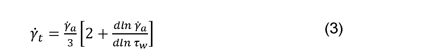
[0052] where s the wall shear rate of a Newtonian fluid
corresponding to the volumetric flow rate
 Finally, a third order polynomial is fit to five consecutive data points to numerically determine the local differential correction term for each data point.
[0053] Microfluidic Printheads: The printheads are machined from acrylic (McMaster Carr) in four pieces using a CNC-mill (Wabeco). Two pieces formed the microchannels and the other two formed the tapped inlets for the inks. Polished (Buelar EcoMet250) surfaces are solvent welded together by soaking the surfaces in acetone for one minute then pressing them together. Fine features are preserved during solvent welding by infilling them with wax prior to solvent welding. The outlet is machined into the printhead after all four pieces are solvent-welded together. The nozzle body is then machined down and polished to remove excess materials and Leur lock adapters are screwed into the inlets. Finally, the wax is removed from the microchannels.
[0054] Modeling Fluid Flow: To model fluid flow through the microfluidic printhead, the Reynolds number given by:
calculated, where is the density of the fluid, is the mean
velocity in the narrow section of the printhead
 , and is the rate
dependent viscosity described by the HB model at the characteristic shear in the flow through the nozzle. Even at the highest flow rates
 the ink flow is laminar.
[0055] The governing equations for the evolution of the pressure in each rin r rmin fr m m l n on each syringe

[0056] where
 are the net volumetric flow rates of material exiting each syringe. The syringe volumes are assumed to be equal
and are approximated as constant in time, since very small
 volumes of ink are printed compared to the syringe volume. Density
changes in the nozzle junction are neglected, and the flow rate through the nozzle is determined from a mass balance on the junction:

[0057] The relationship between pressure drop∆ ^ ^ and net volumetric flow rate ^ ^ through any channel is determined by the equation for steady flow of a HB fluid through a cylindrical pipe with radius

[0059] Eqs. (4)–(7) yield a system of coupled differential equations to determine the evolution of the pressures and flow rates in the nozzle. During the start-up process, ; hence, the initial conditions for

pressures
 are determined by implicitly solving Eq. (7) for these imposed flow rates. For Newtonian materials with the same viscosity
 (7) becomes
 , for which Eqs. (4)–(5) are linear and can be solved exactly. However, for HB materials, Eqs. (4)–(5) are non-linear, but can be approximated using a first order Maclaurin series in time ^ to determine the evolution of the pressure profile

[0060] where
 is the elapsed time of either the pulse

or the steady extrusion
 This equation is sequentially evolved from the initial conditions until the long-term oscillatory state is attained.
[0061] Multi-Material 3D Printing: Inks (3 mL) are loaded into the syringes and then centrifuged in custom holders at 3,000 RPM (IEC Centra CL2, Thermo Scientific) for 1 hour. Hexane is then pulled into each syringe and
quickly expelled to assist with removal of air at the exit of the syringe. Inks are printed through the microfluidic printhead using two opposed syringe pumps (PHD Ultra, Harvard Apparatus).
[0062] A confocal microscope (LSM710, Zeiss) is used to image the printed filaments. A 7 x 7 array of z-stacks is generated using a commercial stitching algorithm (Imaris 7.6.4, Bitplane Scientific Software) from∆z = 9 µm increments. The intensity of each image is rescaled to compensate for the minimal level of speckling caused by QD aggregates in the PDMS. The slices are then summed and scaled to generate the final images, which are analyzed using Matlab (MathWorks) to determine the transition length and variation in filament width. This analysis is similar to the procedure for identifying edge sharpness according to the ISO-13660 protocols. Line edges are defined as the point from the top and bottom edge of the image for which the signal intensity is above the background noise for at least five consecutive pixels.
[0063] Since the printing speed is held constant, a large value of
synchronization. This error may arise at the beginning and ending of each transition when, for a short time, only one pump is running at the full pulse strength. The amount of ink pumped or not pumped during the beginning or end of the transition is given . These complicating factors are
 dependent on the ink formulation, loading, and setup of the printing system. Thus, Eq. (1), though instructive, may be only qualitatively valid for this system, and calibration may be required for each material.
[0064] Although the present invention has been described in
considerable detail with reference to certain embodiments thereof, other embodiments are possible without departing from the present invention. The spirit and scope of the appended claims should not be limited, therefore, to the description of the preferred embodiments contained herein. All embodiments that come within the meaning of the claims, either literally or by equivalence, are intended to be embraced therein. Furthermore, the advantages described above are not necessarily the only advantages of the invention, and it is not necessarily expected that all of the described advantages will be achieved with every embodiment of the invention.
Claims
1. A printhead for 3D printing of multiple materials, the printhead comprising:
a nozzle body comprising:
at least two ink delivery channels joined together at a downstream end of each channel and comprising a single outlet;
a transition channel having an inlet connected to the single outlet of the ink delivery channels, the transition channel comprising a width d2; and
an expansion channel having an inlet connected to an outlet of the transition channel, the expansion channel comprising a width d3 greater than the width d2,
wherein the expansion channel comprises an outlet for extrusion therethrough of a continuous filament comprising more than one material.
2. The printhead of claim 1, wherein the nozzle body is a monolithic body comprising a single piece.
3. The printhead of claim 1, wherein the nozzle body is a modular body comprising multiple pieces.
4. The printhead of any one of claims 1-3, wherein each of the ink delivery channels is oriented at an angle of from about 30° to about 90° with respect to a longitudinal axis of the transition channel.
5. The printhead of claim 4, wherein the longitudinal axis of the transition channel is aligned with a longitudinal axis of the expansion channel.
6. The printhead of any one of claims 1-5, wherein a cross- sectional area of each of the ink delivery channels is constant or increases along a length thereof in a direction away from the single outlet.
7. The printhead of any one of claims 1-6, wherein a cross- sectional area of each of the transition channel and the expansion channel is constant or variable along a length thereof.
8. The printhead of any one of claims 1-7, wherein a width w of each of the ink delivery channels at the downstream end does not exceed the width d2 of the transition channel at the inlet thereof.
9. The printhead of any one of claims 1-8, wherein each of the ink delivery channels comprises a square, rectangular, triangular or semi- circular cross-section.
10. The printhead of any one of claims 1-9, wherein each of the ink delivery channels comprises a width w and a height h, and wherein a ratio of the width w to the height h is from about 1 to about 1.5.
11. The printhead of claim 10, wherein each of the width w and the height h is from about 10 microns to about 400 microns.
12. The printhead of any one of claims 1-11, wherein each of the transition channel and the expansion channel comprises a circular cross- section, the width d2 being a diameter d2 and the width d3 being a diameter d3.
13. The printhead of any one of claims 1-12, wherein a ratio of d3/d2 is at least about 1.5.
14. The printhead of claim 13, wherein the ratio of d3/d2 is at least about 2.
15. The printhead of any one of claims 1-14, wherein the width d2 is from about 10 microns to about 400 microns.
16. The printhead of any one of claims 1-15, wherein the width d3 is from about 20 microns to about 800 microns.
17. The printhead of any one of claims 1-16, wherein each of the ink delivery channels comprises a length l1 of from about 0.5 mm to about 2 mm.
18. The printhead of any one of claims 1-17, wherein a length l2 of the transition channel is from about 10 microns to about 400 microns.
19. The printhead of any one of claims 1-18, further comprising a transition region between the transition channel and the expansion channel where the width d2 gradually increases to the width d3.
20. The printhead of any one of claims 1-18, wherein there is no transition region between the transition channel and the expansion channel, the width d2 abruptly increasing to the width d3.
21. A method of printing multiple materials out of a single
printhead, the method comprising;
providing a nozzle body comprising at least a first ink delivery channel and a second ink delivery channel in fluid communication with a nozzle outlet;
forcing a first ink formulation to flow through the first ink delivery channel while preventing a second ink formulation from flowing through the second delivery channel, thereby extruding through the nozzle outlet a continuous filament comprising only the first ink formulation over a
predetermined length thereof; and
forcing the second ink formulation to flow through the second ink delivery channel while preventing the first ink formulation from flowing
through the first delivery channel, wherein the continuous filament being extruded from the nozzle outlet comprises only the second ink formulation over a predetermined length thereof,
thereby 3D printing a single continuous filament comprising multiple materials.
22. The method of claim 21, further comprising transitioning from the first ink formulation to the second ink formulation, the transitioning comprising, after forcing the first ink formulation to flow through the first delivery channel, withdrawing the first ink formulation from the first ink delivery channel while introducing the second ink formulation into the second delivery channel.
23. The method of claim 22, wherein withdrawing the first ink formulation from the first ink delivery channel comprises applying a withdrawal pulse to the first ink delivery channel, and wherein introducing the second ink formulation into the second delivery channel comprises applying an infusion pulse to the second ink delivery channel, thereby decompressing the first ink formulation while compressing the second ink formulation, wherein the continuous filament being extruded from the nozzle outlet comprises both the first ink formulation and the second ink formulation over a transition length thereof.
24. The method of claim 23, wherein the transition length is about 600 microns or less.
25. The method of any one of claims 23-24, wherein the infusion pulse and the withdrawal pulse are applied for a time duration of from about 0.5 sec to about 2 sec.
26. The method of any one of claims 21-25, wherein each of the first and second ink formulations is forced to flow through the respective first and second delivery channels at a steady volumetric flow rate.
27. The method of claim 26, wherein the steady volumetric flow rate is from about 10 µL/min to about 100 µL/min.
28. The method of claim 26 or 27, wherein the steady volumetric flow rate of the first ink formulation is the same as or different from that of the second ink formulation.
29. The method of any one of claims 23-28, wherein each of the infusion pulse and the withdrawal pulse is applied at a pulse strength of from about 20 to about 100 times the steady volumetric flow rate.
30. The method of any one of claims 23-29, wherein the infusion pulse is applied at a pulse strength of from about 200 µL/min to about 2000 µL/min.
31. The method of claim 30, wherein the pulse strength is from about 600 µL/min to about 1600 µL/min.
32. The method of any one of claims 23-31, wherein the
withdrawal pulse is applied at a pulse strength from about -200 µL/min to about -2000 µL/min.
33. The method of any one of claims 21-25, wherein each of the first and second ink formulations is forced to flow through the respective first and second delivery channels at a steady pressure.
34. The method of claim 33, wherein applying the infusion pulse comprises increasing the pressure and wherein applying the withdrawal pulse comprises decreasing the pressure.
35. The method of any one of claims 21-34, wherein the first ink delivery channel is operatively connected to a first pump and a second ink delivery channel is operatively connected to second pump.
36. The method of any one of claims 21-35, wherein the ink formulation comprises a polymer.
37. The method of any one of claims 21-36, wherein the ink formulation comprises PDMS.
38. The method of any one of claims 21-37, further comprising repeating the forcing and applying as desired,
wherein, after forcing the second ink formulation to flow through the second delivery channel, a withdrawal pulse is applied to the second ink delivery channel while an infusion pulse is applied to the first ink delivery channel, thereby decompressing the second ink formulation while
compressing the first ink formulation, wherein the continuous filament being extruded from the nozzle outlet comprises both the second ink formulation and the first ink formulation over a transition length thereof.
39. A method of printing multiple materials out of a single
printhead, the method comprising;
providing a nozzle body comprising at least a first ink delivery channel and a second ink delivery channel in fluid communication with a nozzle outlet;
forcing a first ink formulation to flow through the first ink delivery channel while forcing a second ink formulation to flow through the second delivery channel, thereby extruding through the nozzle outlet a continuous filament comprising the first ink formulation and the second ink formulation over a predetermined length thereof.
40. The method of claim 39, wherein each of the first and second ink formulations is forced to flow through the respective first and second delivery channels at a steady volumetric flow rate.
41. The method of claim 39 or 40, wherein a volume ratio of the first ink formulation to the second ink formulation over the predetermined
length of the continuous filament may range from greater than 0 to less than 1.
42. The method of any one of claims 39-41, wherein the first ink formulation flows at a first steady volumetric flow rate Q1 and the second ink formulation flows at a second steady volumetric flow rate Q2, Q1 being controlled independently from Q2.
43. The method of claim 39, wherein the first and second ink formulations are forced to flow through the respective first and second delivery channels at a steady pressure.
Applications Claiming Priority (2)
| Application Number | Priority Date | Filing Date | Title |
|---|---|---|---|
| US201562133039P | 2015-03-13 | 2015-03-13 | |
| US62/133,039 | 2015-03-13 |
Publications (1)
| Publication Number | Publication Date |
|---|---|
| WO2016149032A1 true WO2016149032A1 (en) | 2016-09-22 |
Family
ID=56920433
Family Applications (1)
| Application Number | Title | Priority Date | Filing Date |
|---|---|---|---|
| PCT/US2016/021738 Ceased WO2016149032A1 (en) | 2015-03-13 | 2016-03-10 | Printhead and method for 3d printing of multiple materials |
Country Status (1)
| Country | Link |
|---|---|
| WO (1) | WO2016149032A1 (en) |
Cited By (17)
| Publication number | Priority date | Publication date | Assignee | Title |
|---|---|---|---|---|
| WO2018106705A1 (en) * | 2016-12-08 | 2018-06-14 | President And Fellows Of Harvard College | 3d printed core-shell filament and method of 3d printing a core-shell filament |
| US10073346B2 (en) | 2016-07-08 | 2018-09-11 | Cypre, Inc. | Apparatus for patterning hydrogels into multi-well plates |
| WO2018205149A1 (en) * | 2017-05-09 | 2018-11-15 | 黄卫东 | 3d print head, 3d printing device, control method for 3d print head |
| US10864673B2 (en) | 2017-08-18 | 2020-12-15 | Ppg Industries Ohio, Inc. | Additive manufacturing using polyurea materials |
| US10982105B2 (en) | 2014-11-24 | 2021-04-20 | Ppg Industries Ohio, Inc. | Methods for reactive three-dimensional printing by extrusion |
| WO2021076853A1 (en) * | 2018-11-08 | 2021-04-22 | Lawrence Livermore National Security, Llc | Multimaterial powder bed patterning for additive manufacturing method |
| WO2022010411A1 (en) | 2020-07-09 | 2022-01-13 | Ememo Solutions Ab | A three-dimensional imaging apparatus having multiple passive nozzles for modeling a multi material three-dimensional object |
| US11866594B2 (en) | 2017-06-27 | 2024-01-09 | Lawrence Livermore National Security, Llc | Elastomeric shape memory polymer composites |
| US12005717B2 (en) | 2019-10-07 | 2024-06-11 | Hewlett-Packard Development Company, L.P. | Printer valve assemblies |
| CN119458915A (en) * | 2025-01-10 | 2025-02-18 | 芯体素(杭州)科技发展有限公司 | A chip sealing dam preparation method, device, equipment and medium |
| US12226983B2 (en) | 2019-02-11 | 2025-02-18 | Ppg Industries Ohio, Inc. | Multilayer systems and methods of making multilayer systems |
| US12269091B2 (en) | 2020-11-30 | 2025-04-08 | Lawrence Livermore National Security, Llc | System and method for multimaterial powder bed patterning for use in additive manufacturing |
| US12384097B2 (en) | 2017-08-18 | 2025-08-12 | Ppg Industries Ohio, Inc. | Additive manufacturing using reactive compositions |
| US12434434B2 (en) | 2019-02-11 | 2025-10-07 | Ppg Industries Ohio, Inc. | Methods of making chemically resistant sealing components |
| US12441049B2 (en) | 2019-02-11 | 2025-10-14 | Ppg Industries Ohio, Inc. | 3D printing of seal caps |
| US12503544B2 (en) | 2019-02-11 | 2025-12-23 | Ppg Industries Ohio, Inc. | Elastomeric compositions and methods of use |
| US12516216B2 (en) | 2017-06-27 | 2026-01-06 | Lawrence Livermore National Security, Llc | Microballoon-facilitated tunable porosity of elastomeric shape memory polymer composites |
Citations (3)
| Publication number | Priority date | Publication date | Assignee | Title |
|---|---|---|---|---|
| US8827684B1 (en) * | 2013-12-23 | 2014-09-09 | Radiant Fabrication | 3D printer and printhead unit with multiple filaments |
| US20140314954A1 (en) * | 2011-07-01 | 2014-10-23 | The Board Of Trustees Of The University Of Illinois | Multinozzle deposition system for direct write applications |
| WO2014209994A2 (en) * | 2013-06-24 | 2014-12-31 | President And Fellows Of Harvard College | Printed three-dimensional (3d) functional part and method of making |
-
2016
- 2016-03-10 WO PCT/US2016/021738 patent/WO2016149032A1/en not_active Ceased
Patent Citations (3)
| Publication number | Priority date | Publication date | Assignee | Title |
|---|---|---|---|---|
| US20140314954A1 (en) * | 2011-07-01 | 2014-10-23 | The Board Of Trustees Of The University Of Illinois | Multinozzle deposition system for direct write applications |
| WO2014209994A2 (en) * | 2013-06-24 | 2014-12-31 | President And Fellows Of Harvard College | Printed three-dimensional (3d) functional part and method of making |
| US8827684B1 (en) * | 2013-12-23 | 2014-09-09 | Radiant Fabrication | 3D printer and printhead unit with multiple filaments |
Cited By (27)
| Publication number | Priority date | Publication date | Assignee | Title |
|---|---|---|---|---|
| US12187904B2 (en) | 2014-11-24 | 2025-01-07 | Ppg Industries Ohio, Inc. | Coreactive materials and methods for three-dimensional printing |
| US11634599B2 (en) | 2014-11-24 | 2023-04-25 | Ppg Industries Ohio, Inc. | Coreactive materials and methods for three-dimensional printing |
| US11920046B2 (en) | 2014-11-24 | 2024-03-05 | Ppg Industries Ohio, Inc. | Coreactive materials and methods for three-dimensional printing |
| US11220610B2 (en) | 2014-11-24 | 2022-01-11 | Ppg Industries Ohio, Inc. | Methods for reactive three-dimensional printing by inkjet printing |
| US11028279B2 (en) | 2014-11-24 | 2021-06-08 | Ppg Industries Ohio, Inc. | Coreactive materials and methods for three-dimensional printing |
| US10982105B2 (en) | 2014-11-24 | 2021-04-20 | Ppg Industries Ohio, Inc. | Methods for reactive three-dimensional printing by extrusion |
| US10423071B2 (en) | 2016-07-08 | 2019-09-24 | Cypre, Inc. | Methods for patterning hydrogels into multi-well plates |
| US10073346B2 (en) | 2016-07-08 | 2018-09-11 | Cypre, Inc. | Apparatus for patterning hydrogels into multi-well plates |
| US11207831B2 (en) | 2016-12-08 | 2021-12-28 | President And Fellows Of Harvard College | 3D printed core-shell filament and method of 3D printing a core-shell filament |
| WO2018106705A1 (en) * | 2016-12-08 | 2018-06-14 | President And Fellows Of Harvard College | 3d printed core-shell filament and method of 3d printing a core-shell filament |
| US11104070B2 (en) | 2017-05-09 | 2021-08-31 | Weidong Huang | 3D printing head, 3D printing device and control method of 3D printing head |
| WO2018205149A1 (en) * | 2017-05-09 | 2018-11-15 | 黄卫东 | 3d print head, 3d printing device, control method for 3d print head |
| US11866594B2 (en) | 2017-06-27 | 2024-01-09 | Lawrence Livermore National Security, Llc | Elastomeric shape memory polymer composites |
| US12516216B2 (en) | 2017-06-27 | 2026-01-06 | Lawrence Livermore National Security, Llc | Microballoon-facilitated tunable porosity of elastomeric shape memory polymer composites |
| US10864673B2 (en) | 2017-08-18 | 2020-12-15 | Ppg Industries Ohio, Inc. | Additive manufacturing using polyurea materials |
| US12384097B2 (en) | 2017-08-18 | 2025-08-12 | Ppg Industries Ohio, Inc. | Additive manufacturing using reactive compositions |
| US12138850B2 (en) | 2017-08-18 | 2024-11-12 | Ppg Industries Ohio, Inc. | Additive manufacturing using polyurea materials |
| WO2021076853A1 (en) * | 2018-11-08 | 2021-04-22 | Lawrence Livermore National Security, Llc | Multimaterial powder bed patterning for additive manufacturing method |
| US11697246B2 (en) | 2018-11-08 | 2023-07-11 | Lawrence Livermore National Security, Llc | Multimaterial powder bed patterning for additive manufacturing method |
| US12441049B2 (en) | 2019-02-11 | 2025-10-14 | Ppg Industries Ohio, Inc. | 3D printing of seal caps |
| US12226983B2 (en) | 2019-02-11 | 2025-02-18 | Ppg Industries Ohio, Inc. | Multilayer systems and methods of making multilayer systems |
| US12434434B2 (en) | 2019-02-11 | 2025-10-07 | Ppg Industries Ohio, Inc. | Methods of making chemically resistant sealing components |
| US12503544B2 (en) | 2019-02-11 | 2025-12-23 | Ppg Industries Ohio, Inc. | Elastomeric compositions and methods of use |
| US12005717B2 (en) | 2019-10-07 | 2024-06-11 | Hewlett-Packard Development Company, L.P. | Printer valve assemblies |
| WO2022010411A1 (en) | 2020-07-09 | 2022-01-13 | Ememo Solutions Ab | A three-dimensional imaging apparatus having multiple passive nozzles for modeling a multi material three-dimensional object |
| US12269091B2 (en) | 2020-11-30 | 2025-04-08 | Lawrence Livermore National Security, Llc | System and method for multimaterial powder bed patterning for use in additive manufacturing |
| CN119458915A (en) * | 2025-01-10 | 2025-02-18 | 芯体素(杭州)科技发展有限公司 | A chip sealing dam preparation method, device, equipment and medium |
Similar Documents
| Publication | Publication Date | Title |
|---|---|---|
| WO2016149032A1 (en) | Printhead and method for 3d printing of multiple materials | |
| Hardin et al. | Microfluidic printheads for multimaterial 3D printing of viscoelastic inks | |
| DE60216748T2 (en) | FLUID PUMP SYSTEM | |
| EP1654068B1 (en) | Microdosing device and method for the dosed delivery of liquids | |
| US8524174B2 (en) | Fluid cartridge, pump and fluid valve arrangement | |
| Lade Jr et al. | Dynamics of capillary-driven flow in 3D printed open microchannels | |
| EP2486287B1 (en) | Fluidic actuator and method of manufacture | |
| Fu et al. | Breakup dynamics of slender droplet formation in shear-thinning fluids in flow-focusing devices | |
| EP1274501B2 (en) | Mixer | |
| US20240269934A1 (en) | Three-dimensional printing of hydrophobic materials in fumed silica suspension | |
| US10221060B2 (en) | Microvolume-liquid dispensing method and microvolume-liquid dispenser | |
| CN102458785B (en) | Method and apparatus for preparing a paste compound for sealing insulating glass panes | |
| DE102016225209A1 (en) | Pipetting device for improved pulse-like liquid pipetting | |
| DE102017201114A1 (en) | A pipetting device for pulse-like pipetting with a pipetting piston movement regulated on the basis of a detection of the working gas pressure | |
| WO2012048685A1 (en) | Flow cell with cavity and diaphragm | |
| Shin et al. | Centrifuge-based step emulsification device for simple and fast generation of monodisperse picoliter droplets | |
| US20220193980A1 (en) | Systems and methods for printing a three-dimensional object | |
| Berthier et al. | Suspended microflows between vertical parallel walls | |
| EP3820614A1 (en) | Pipetting device for pulsed pipetting with a pipetting piston movement controlled on the basis of a detection of the piston position | |
| JP2007526056A (en) | Multi-component compound generator and method | |
| Wang et al. | An electrode design for droplet dispensing with accurate volume in electro-wetting-based microfluidics | |
| CN110214047A (en) | Low-complexity flow control in microfluid mixer | |
| JP2005324189A (en) | Fluid ejecting method, fluid ejecting apparatus, and display panel | |
| Kumar et al. | Effect of pressure-dependent slip on flow curve multiplicity | |
| EP3144056B1 (en) | Low dispersion, fast response mixing and dispensing system and method |
Legal Events
| Date | Code | Title | Description |
|---|---|---|---|
| 121 | Ep: the epo has been informed by wipo that ep was designated in this application |
Ref document number: 16765458 Country of ref document: EP Kind code of ref document: A1 |
|
| NENP | Non-entry into the national phase |
Ref country code: DE |
|
| 122 | Ep: pct application non-entry in european phase |
Ref document number: 16765458 Country of ref document: EP Kind code of ref document: A1 |