WO2015001749A1 - Dispositif d'entraînement de portière de véhicule - Google Patents
Dispositif d'entraînement de portière de véhicule Download PDFInfo
- Publication number
- WO2015001749A1 WO2015001749A1 PCT/JP2014/003316 JP2014003316W WO2015001749A1 WO 2015001749 A1 WO2015001749 A1 WO 2015001749A1 JP 2014003316 W JP2014003316 W JP 2014003316W WO 2015001749 A1 WO2015001749 A1 WO 2015001749A1
- Authority
- WO
- WIPO (PCT)
- Prior art keywords
- door
- vehicle
- pop
- holding
- side door
- Prior art date
- Legal status (The legal status is an assumption and is not a legal conclusion. Google has not performed a legal analysis and makes no representation as to the accuracy of the status listed.)
- Ceased
Links
Images


Classifications
-
- E—FIXED CONSTRUCTIONS
- E05—LOCKS; KEYS; WINDOW OR DOOR FITTINGS; SAFES
- E05F—DEVICES FOR MOVING WINGS INTO OPEN OR CLOSED POSITION; CHECKS FOR WINGS; WING FITTINGS NOT OTHERWISE PROVIDED FOR, CONCERNED WITH THE FUNCTIONING OF THE WING
- E05F15/00—Power-operated mechanisms for wings
- E05F15/70—Power-operated mechanisms for wings with automatic actuation
-
- E—FIXED CONSTRUCTIONS
- E05—LOCKS; KEYS; WINDOW OR DOOR FITTINGS; SAFES
- E05F—DEVICES FOR MOVING WINGS INTO OPEN OR CLOSED POSITION; CHECKS FOR WINGS; WING FITTINGS NOT OTHERWISE PROVIDED FOR, CONCERNED WITH THE FUNCTIONING OF THE WING
- E05F15/00—Power-operated mechanisms for wings
- E05F15/60—Power-operated mechanisms for wings using electrical actuators
- E05F15/603—Power-operated mechanisms for wings using electrical actuators using rotary electromotors
- E05F15/611—Power-operated mechanisms for wings using electrical actuators using rotary electromotors for swinging wings
-
- E—FIXED CONSTRUCTIONS
- E05—LOCKS; KEYS; WINDOW OR DOOR FITTINGS; SAFES
- E05C—BOLTS OR FASTENING DEVICES FOR WINGS, SPECIALLY FOR DOORS OR WINDOWS
- E05C17/00—Devices for holding wings open; Devices for limiting opening of wings or for holding wings open by a movable member extending between frame and wing; Braking devices, stops or buffers, combined therewith
-
- E—FIXED CONSTRUCTIONS
- E05—LOCKS; KEYS; WINDOW OR DOOR FITTINGS; SAFES
- E05F—DEVICES FOR MOVING WINGS INTO OPEN OR CLOSED POSITION; CHECKS FOR WINGS; WING FITTINGS NOT OTHERWISE PROVIDED FOR, CONCERNED WITH THE FUNCTIONING OF THE WING
- E05F15/00—Power-operated mechanisms for wings
- E05F15/70—Power-operated mechanisms for wings with automatic actuation
- E05F15/77—Power-operated mechanisms for wings with automatic actuation using wireless control
-
- E—FIXED CONSTRUCTIONS
- E05—LOCKS; KEYS; WINDOW OR DOOR FITTINGS; SAFES
- E05Y—INDEXING SCHEME ASSOCIATED WITH SUBCLASSES E05D AND E05F, RELATING TO CONSTRUCTION ELEMENTS, ELECTRIC CONTROL, POWER SUPPLY, POWER SIGNAL OR TRANSMISSION, USER INTERFACES, MOUNTING OR COUPLING, DETAILS, ACCESSORIES, AUXILIARY OPERATIONS NOT OTHERWISE PROVIDED FOR, APPLICATION THEREOF
- E05Y2201/00—Constructional elements; Accessories therefor
- E05Y2201/20—Brakes; Disengaging means; Holders; Stops; Valves; Accessories therefor
- E05Y2201/21—Brakes
-
- E—FIXED CONSTRUCTIONS
- E05—LOCKS; KEYS; WINDOW OR DOOR FITTINGS; SAFES
- E05Y—INDEXING SCHEME ASSOCIATED WITH SUBCLASSES E05D AND E05F, RELATING TO CONSTRUCTION ELEMENTS, ELECTRIC CONTROL, POWER SUPPLY, POWER SIGNAL OR TRANSMISSION, USER INTERFACES, MOUNTING OR COUPLING, DETAILS, ACCESSORIES, AUXILIARY OPERATIONS NOT OTHERWISE PROVIDED FOR, APPLICATION THEREOF
- E05Y2201/00—Constructional elements; Accessories therefor
- E05Y2201/60—Suspension or transmission members; Accessories therefor
- E05Y2201/622—Suspension or transmission members elements
- E05Y2201/71—Toothed gearing
- E05Y2201/716—Pinions
-
- E—FIXED CONSTRUCTIONS
- E05—LOCKS; KEYS; WINDOW OR DOOR FITTINGS; SAFES
- E05Y—INDEXING SCHEME ASSOCIATED WITH SUBCLASSES E05D AND E05F, RELATING TO CONSTRUCTION ELEMENTS, ELECTRIC CONTROL, POWER SUPPLY, POWER SIGNAL OR TRANSMISSION, USER INTERFACES, MOUNTING OR COUPLING, DETAILS, ACCESSORIES, AUXILIARY OPERATIONS NOT OTHERWISE PROVIDED FOR, APPLICATION THEREOF
- E05Y2201/00—Constructional elements; Accessories therefor
- E05Y2201/60—Suspension or transmission members; Accessories therefor
- E05Y2201/622—Suspension or transmission members elements
- E05Y2201/71—Toothed gearing
- E05Y2201/722—Racks
-
- E—FIXED CONSTRUCTIONS
- E05—LOCKS; KEYS; WINDOW OR DOOR FITTINGS; SAFES
- E05Y—INDEXING SCHEME ASSOCIATED WITH SUBCLASSES E05D AND E05F, RELATING TO CONSTRUCTION ELEMENTS, ELECTRIC CONTROL, POWER SUPPLY, POWER SIGNAL OR TRANSMISSION, USER INTERFACES, MOUNTING OR COUPLING, DETAILS, ACCESSORIES, AUXILIARY OPERATIONS NOT OTHERWISE PROVIDED FOR, APPLICATION THEREOF
- E05Y2400/00—Electronic control; Electrical power; Power supply; Power or signal transmission; User interfaces
- E05Y2400/10—Electronic control
- E05Y2400/20—Electronic control of brakes, disengaging means, holders or stops
-
- E—FIXED CONSTRUCTIONS
- E05—LOCKS; KEYS; WINDOW OR DOOR FITTINGS; SAFES
- E05Y—INDEXING SCHEME ASSOCIATED WITH SUBCLASSES E05D AND E05F, RELATING TO CONSTRUCTION ELEMENTS, ELECTRIC CONTROL, POWER SUPPLY, POWER SIGNAL OR TRANSMISSION, USER INTERFACES, MOUNTING OR COUPLING, DETAILS, ACCESSORIES, AUXILIARY OPERATIONS NOT OTHERWISE PROVIDED FOR, APPLICATION THEREOF
- E05Y2400/00—Electronic control; Electrical power; Power supply; Power or signal transmission; User interfaces
- E05Y2400/10—Electronic control
- E05Y2400/30—Electronic control of motors
- E05Y2400/304—Voltage control
-
- E—FIXED CONSTRUCTIONS
- E05—LOCKS; KEYS; WINDOW OR DOOR FITTINGS; SAFES
- E05Y—INDEXING SCHEME ASSOCIATED WITH SUBCLASSES E05D AND E05F, RELATING TO CONSTRUCTION ELEMENTS, ELECTRIC CONTROL, POWER SUPPLY, POWER SIGNAL OR TRANSMISSION, USER INTERFACES, MOUNTING OR COUPLING, DETAILS, ACCESSORIES, AUXILIARY OPERATIONS NOT OTHERWISE PROVIDED FOR, APPLICATION THEREOF
- E05Y2400/00—Electronic control; Electrical power; Power supply; Power or signal transmission; User interfaces
- E05Y2400/10—Electronic control
- E05Y2400/40—Control units therefor
-
- E—FIXED CONSTRUCTIONS
- E05—LOCKS; KEYS; WINDOW OR DOOR FITTINGS; SAFES
- E05Y—INDEXING SCHEME ASSOCIATED WITH SUBCLASSES E05D AND E05F, RELATING TO CONSTRUCTION ELEMENTS, ELECTRIC CONTROL, POWER SUPPLY, POWER SIGNAL OR TRANSMISSION, USER INTERFACES, MOUNTING OR COUPLING, DETAILS, ACCESSORIES, AUXILIARY OPERATIONS NOT OTHERWISE PROVIDED FOR, APPLICATION THEREOF
- E05Y2400/00—Electronic control; Electrical power; Power supply; Power or signal transmission; User interfaces
- E05Y2400/10—Electronic control
- E05Y2400/44—Sensors not directly associated with the wing movement
- E05Y2400/446—Vehicle state sensors, e.g. parked or inclination
-
- E—FIXED CONSTRUCTIONS
- E05—LOCKS; KEYS; WINDOW OR DOOR FITTINGS; SAFES
- E05Y—INDEXING SCHEME ASSOCIATED WITH SUBCLASSES E05D AND E05F, RELATING TO CONSTRUCTION ELEMENTS, ELECTRIC CONTROL, POWER SUPPLY, POWER SIGNAL OR TRANSMISSION, USER INTERFACES, MOUNTING OR COUPLING, DETAILS, ACCESSORIES, AUXILIARY OPERATIONS NOT OTHERWISE PROVIDED FOR, APPLICATION THEREOF
- E05Y2400/00—Electronic control; Electrical power; Power supply; Power or signal transmission; User interfaces
- E05Y2400/10—Electronic control
- E05Y2400/44—Sensors not directly associated with the wing movement
- E05Y2400/447—Moisture or submergence sensors
-
- E—FIXED CONSTRUCTIONS
- E05—LOCKS; KEYS; WINDOW OR DOOR FITTINGS; SAFES
- E05Y—INDEXING SCHEME ASSOCIATED WITH SUBCLASSES E05D AND E05F, RELATING TO CONSTRUCTION ELEMENTS, ELECTRIC CONTROL, POWER SUPPLY, POWER SIGNAL OR TRANSMISSION, USER INTERFACES, MOUNTING OR COUPLING, DETAILS, ACCESSORIES, AUXILIARY OPERATIONS NOT OTHERWISE PROVIDED FOR, APPLICATION THEREOF
- E05Y2400/00—Electronic control; Electrical power; Power supply; Power or signal transmission; User interfaces
- E05Y2400/10—Electronic control
- E05Y2400/45—Control modes
-
- E—FIXED CONSTRUCTIONS
- E05—LOCKS; KEYS; WINDOW OR DOOR FITTINGS; SAFES
- E05Y—INDEXING SCHEME ASSOCIATED WITH SUBCLASSES E05D AND E05F, RELATING TO CONSTRUCTION ELEMENTS, ELECTRIC CONTROL, POWER SUPPLY, POWER SIGNAL OR TRANSMISSION, USER INTERFACES, MOUNTING OR COUPLING, DETAILS, ACCESSORIES, AUXILIARY OPERATIONS NOT OTHERWISE PROVIDED FOR, APPLICATION THEREOF
- E05Y2400/00—Electronic control; Electrical power; Power supply; Power or signal transmission; User interfaces
- E05Y2400/80—User interfaces
- E05Y2400/85—User input means
- E05Y2400/8515—Smart phones; Tablets
-
- E—FIXED CONSTRUCTIONS
- E05—LOCKS; KEYS; WINDOW OR DOOR FITTINGS; SAFES
- E05Y—INDEXING SCHEME ASSOCIATED WITH SUBCLASSES E05D AND E05F, RELATING TO CONSTRUCTION ELEMENTS, ELECTRIC CONTROL, POWER SUPPLY, POWER SIGNAL OR TRANSMISSION, USER INTERFACES, MOUNTING OR COUPLING, DETAILS, ACCESSORIES, AUXILIARY OPERATIONS NOT OTHERWISE PROVIDED FOR, APPLICATION THEREOF
- E05Y2400/00—Electronic control; Electrical power; Power supply; Power or signal transmission; User interfaces
- E05Y2400/80—User interfaces
- E05Y2400/85—User input means
- E05Y2400/856—Actuation thereof
- E05Y2400/858—Actuation thereof by body parts, e.g. by feet
- E05Y2400/86—Actuation thereof by body parts, e.g. by feet by hand
-
- E—FIXED CONSTRUCTIONS
- E05—LOCKS; KEYS; WINDOW OR DOOR FITTINGS; SAFES
- E05Y—INDEXING SCHEME ASSOCIATED WITH SUBCLASSES E05D AND E05F, RELATING TO CONSTRUCTION ELEMENTS, ELECTRIC CONTROL, POWER SUPPLY, POWER SIGNAL OR TRANSMISSION, USER INTERFACES, MOUNTING OR COUPLING, DETAILS, ACCESSORIES, AUXILIARY OPERATIONS NOT OTHERWISE PROVIDED FOR, APPLICATION THEREOF
- E05Y2900/00—Application of doors, windows, wings or fittings thereof
- E05Y2900/50—Application of doors, windows, wings or fittings thereof for vehicles
- E05Y2900/53—Type of wing
- E05Y2900/531—Doors
Definitions
- the present invention relates to a vehicle door drive apparatus and a vehicle door drive method, and more specifically, an opening operation from a fully closed state (a state in which the door is completely closed) of a door (for example, a side door) of a vehicle.
- the present invention relates to a vehicle door drive device to be controlled and a vehicle door drive method.
- Patent Document 1 proposes a vehicle door control device that improves the feeling of operation when manually opening and closing a door of a vehicle.
- the vehicle door control device disclosed in Patent Document 1 includes a door drive motor, a lever connected to the vehicle door, an electromagnetic clutch that switches transmission and disconnection of a drive force of the door drive motor to the lever, and the electromagnetic clutch. And a lever operating unit for transmitting a driving force through the lever to the lever.
- the drive force of the door drive motor is output to the lever drive unit as a clutch output according to the connection state of the electromagnetic clutch via the electromagnetic clutch, and the lever drive unit causes the lever to move up and down by the clutch output.
- the clutch output changes in accordance with the distance between the two friction plates of the electromagnetic clutch, and the clutch output serves as a door holding load for the vehicle door.
- the vehicle door control device further includes a door opening degree sensor that detects the position of the vehicle door, and is configured to detect a manual operation of the vehicle door based on an output signal of the door opening degree sensor.
- a door opening degree sensor that detects the position of the vehicle door, and is configured to detect a manual operation of the vehicle door based on an output signal of the door opening degree sensor.
- Patent Document 1 As apparent from the above, in a vehicle capable of manually opening and closing a vehicle door, in order to improve the feeling when manually opening and closing a vehicle door stopped at an arbitrary angle, the above-mentioned Patent Document 1
- the disclosed technology is powerful. However, there are still problems that need to be improved in order to further improve the manual operability of the vehicle door.
- the door when manually opening the vehicle door from the state where the vehicle door is completely closed (hereinafter, also referred to as "full closed state of the vehicle door"), the door as a door holding force Only control to reduce the holding load is performed. Therefore, when the user tries to open the vehicle door manually from the fully closed state, the vehicle door must be operated at least against the weight of the vehicle door itself.
- the present invention has been made in view of such problems, and an object of the present invention is to provide a vehicle capable of manually opening a vehicle door (for example, a side door, a back door, a trunk lid, etc.)
- An object of the present invention is to provide a vehicle door drive device and a vehicle door drive method capable of reducing the operation force required for manually opening the door.
- a first aspect of the present invention is a vehicle door drive device for automatically opening a fully closed door of a vehicle by a predetermined amount which does not become fully open.
- a door drive unit adapted to automatically open the door, and the command by the input unit, the predetermined amount according to the situation of the user or the situation of the vehicle
- an open operating unit adapted to control the door drive to automatically open the door by the determined predetermined amount from the fully closed state.
- a vehicle door drive apparatus which is an input unit for inputting a command for automatically opening a fully closed door of a vehicle by a predetermined amount which does not become fully open;
- a door driving unit adapted to automatically open the door, a door holding unit adapted to generate a holding force for holding the door, and the holding force adapted to hold the door, and in response to the command,
- An open operating unit adapted to control the door drive unit to automatically open the door by the predetermined amount, and a control unit for controlling generation of the holding force of the door holding unit according to the command
- a control unit configured to control the door holding unit in a state in which the holding force is not generated before the door actually starts to move.
- a third aspect of the present invention is a method of driving a vehicle door, which detects whether or not the vehicle is inclined such that the direction of the door of the vehicle to be operated faces the lower side of the vehicle. And a door holding unit adapted to generate a holding force for holding the door and holding the door by the holding force, and the detection unit turns the door hand direction toward the lower side of the vehicle. And a holding force generation unit configured to generate the holding force by controlling the door holding unit when the vehicle is detected to be inclined.
- the door when the vehicle door in the fully closed state is opened, the door is automatically opened by a predetermined amount which does not become the fully open state. Therefore, the operation required when manually opening the vehicle door in the fully closed state Power can be reduced.
- the predetermined amount is changed according to the user's situation or the vehicle's situation or according to the user's desire (according to the user's operation amount for determining the predetermined amount), up to the predetermined amount
- the automatic opening operation of the door can be appropriately performed according to the situation. Further, before the door actually starts to move automatically to the predetermined amount, the door holding portion for generating the holding force to hold the door is not generated so that the door is automatically opened to the predetermined amount.
- the opening operation can be performed well.
- the holding force for holding the door is generated.
- the door is opened from the inside of the vehicle at the time of the inclination, it is possible to reduce that the door runs by itself due to its own weight. Therefore, the operation force required when manually opening the vehicle door at the time of the inclination can be reduced.
- FIG. 5 is a schematic view showing the top surface of the side door in the pop-up position according to an embodiment of the present invention. It is a perspective view of a door holding device in which a side door concerning a 1 embodiment of the present invention is in a pop-up position.
- FIG. 1 is a side view of a part of a vehicle according to the present embodiment.
- a vehicle 100 includes a side door 101 and an opening 101 a formed in the vehicle 100 and passing when a person gets in and out of the vehicle 100.
- the side door 101 is fitted into the opening 101a, and is connected to the opening 101a via a pair of hinges 103 at an edge 110 on the vehicle front side of the opening 101a.
- the side door 101 is pivotable about the hinge 103. That is, the side door 101 is a swing type door.
- An outside handle 104 is provided on the vehicle outside of the side door 101.
- the outside handle 104 is provided with a switch 106 for the user to input a command for automatically opening the side door 104 in the fully closed state by a predetermined amount which does not become the fully open state.
- automatically opening the side door 101 in the fully closed state by a predetermined amount not in the fully open state is referred to as “pop-up opening operation”, and “the side door 101 in the fully closed state is not fully open automatically.
- a command from the user for opening only a fixed amount is called a "pop-up command".
- a user who is outside the vehicle 100 can open the side door 101 (operation to open the side door 101) by operating the outside handle 104 or the switch 106. That is, when the user operates the outside handle 104, the side door 101 can be manually opened. On the other hand, when the user depresses the switch 106, the side door 101 is automatically opened by a predetermined amount which is not fully open by the pop-up opening operation, and is stopped at the position opened by the predetermined amount. The user may manually open the side door 101 stopped at the stop position by applying a force (operating force) to turn the side door 101 outward to the side door 101 stopped at this position. it can.
- the switch 106 functions as an input unit through which the user inputs a pop-up command from the outside of the vehicle.
- the switch 106 also functions as an input unit for inputting information on the user's situation that the user inputs the pop-up instruction from the outside of the vehicle 100.
- the position where the pop-up opening operation is completed (the stop position, that is, the position where the side door 101 is opened from the fully closed state by a predetermined amount related to the pop-up opening operation) is referred to as “pop-up door position”.
- An inside handle 105 is provided inside the vehicle of the side door 101.
- the inside handle 105 is provided with a switch 107 for the user to input a pop-up command.
- the user inside the vehicle 100 can perform the opening operation of the side door 101 by operating the inside handle 105 or the switch 107. That is, when the user operates the inside handle 105, the side door 101 can be opened manually.
- the switch 107 when the user depresses the switch 107, the side door 101 automatically opens up to the position of the pop-up door and stops at the position. The user may manually open the side door 101 stopped at the stop position by applying a force (operating force) to turn the side door 101 outward to the side door 101 stopped at this position. it can.
- the switch 107 functions as an input unit through which the user inputs a pop-up command from the inside of the vehicle.
- the depression of the switch 107 by the user indicates that the user who is trying to operate the side door 101 is inside the vehicle 100. That is, it can be said that the input of the pop-up instruction by the switch 107 is input of the user's situation that the user is inside the vehicle 100. Therefore, it can be said that the switch 107 also functions as an input unit for inputting information related to the user's situation that the user inputs the pop-up instruction from the inside of the vehicle 100.
- the side door 101 includes a door holding device 108 for holding the side door 101 at a predetermined position (in the present embodiment, the pop-up door position), and a striker provided at an edge portion 111 on the vehicle rear side of the opening 101a.
- a latch device 109 for holding the side door 101 in a closed state (a fully closed state or a half door state) with respect to the vehicle 101.
- the latch device 109 has a latch (not shown) and a pole (not shown), and when closing the side door 101, the latch rotates and engages with the striker, and at the same time the pole rotates the latch.
- the side door 101 is held closed.
- the pole is moved to release the rotation stop of the latch, the engagement between the latch and the striker is released, and the side door 101 can be turned.
- FIG. 2 is a perspective view of the door holding device 108 when the side door 101 is fully closed.
- the door holding device 108 can hold the side door 101 at an arbitrary position, and has a so-called free stop function.
- the door holding device 108 has a rail 201 fixed inside the side door 101, a rack 202 engaged with the rail 201 and sliding on the rail 201, meshed with the rack 202, and a relative position to the rack
- a pinion 203 which rotates by movement, an electromagnetic brake 204 connected to the pinion 203, and a lever 205 connected to the rack 202 are provided.
- One end of the lever 205 is connected to the rack 202 so as to pivot around the pin 206.
- the pinion 203 is connected to a shaft which is a rotation shaft of the electromagnetic brake 204.
- the other end of the lever 205 passes through an opening provided on the vehicle front of the side door 101, and is connected to the edge 110 on the vehicle front side of the opening 101a via a bracket (not shown).
- FIG. 3 is a block diagram showing a schematic configuration of a control system in the vehicle door drive device 300 according to the present embodiment.
- Vehicle door drive device 300 includes switches 106 and 107 for the user to input a pop-up command, door holding device 108, drive circuit 307 for driving electromagnetic brake 204 of door holding device 108, and door holding device 108 includes a motor 309 for displacing the rack 202, a drive circuit 308 for driving the motor 309, a radio signal transmission / reception unit 310 for transmitting / receiving radio signals to / from a radio transmitter (not shown), and a side door A pulse sensor 311 for detecting the degree of opening 101 and a control device 301 are provided.
- a control device 301 is a control unit as a control unit that controls the entire vehicle door drive device 300. Further, the control device 301 may be configured to control a configuration other than the vehicle door drive device 300 such as the latch device 109.
- the control device 301 has a CPU 302 that executes processing operations such as various operations, controls, and determinations, and a ROM 303 that stores control programs such as processing to be described later with reference to FIG. .
- the control device 301 has a RAM 304 for temporarily storing data and input data during the processing operation of the CPU 302, and a non-volatile memory 305 such as a flash memory or SRAM. Further, switches 106 and 107 are connected to the control device 301.
- the switch 106 or 107 transmits pop-up command information related to the pop-up command to the control device 301.
- a latch device 109, an electromagnetic brake 204, a motor 309 and the like are connected to the control device 301 via drive circuits 306 to 308, respectively.
- the wireless signal transmission / reception unit 310 transmits an ID information request signal at predetermined time intervals (transmission time intervals) to the outside of the vehicle 100. Also, the wireless signal transmission / reception unit 310 receives an ID information signal transmitted from a predetermined wireless transmitter.
- the wireless transmitter is a portable device having a wireless communication function, such as a portable key, a smartphone, a tablet, or the like, which is different from the vehicle 100, having a communication function such as wireless communication.
- the wireless transmitter holds ID information indicating a predetermined vehicle ID in a memory unit.
- the wireless transmitter transmits an ID information signal including ID information for specifying a predetermined vehicle stored in its own memory unit.
- the wireless signal transmission / reception unit 310 receives the ID information signal.
- a pop-up command may be input from the wireless transmitter.
- a switch for causing the user to input a pop-up command to the wireless transmitter may be provided.
- the wireless transmitter transmits pop-up command information to the vehicle 100, and the wireless signal transmission / reception unit 310 receives the pop-up command information transmitted from the wireless transmitter. Therefore, in this case, the wireless signal transmission / reception unit 310 functions as an input unit for inputting the pop-up command.
- the pop-up opening operation may be performed when the user operates the outside handle 104 or the inside handle 105 to open the fully closed side door 101 as a trigger.
- a switch that is turned on in conjunction with the operation of the outside handle 104 or the inside handle 105 in the fully closed state, and the switch transmits pop-up command information to the control device 301 when the switch is turned on.
- the pop-up command input unit may be configured.
- the pulse sensor 311 is provided in a motor 309 for driving the rack 202 (lever 205), and transmits a pulse signal corresponding to the number of rotations of the motor 309 to the control device 301.
- the control device 301 can recognize the number of rotations of the motor 309 from the pulse signal received from the pulse sensor 311. Therefore, the control device 301 can calculate the movement amount of the rack 202 based on the rotation speed of the motor 309, and can know how much the side door 101 is opened (opening degree) from the movement amount. For example, the dimensions of members related to the opening operation of the side door 101, such as the rack 202, the lever 205, and the side door 101, do not change, so the moving amount is related to the opening degree by table formation or functionalization.
- the control device 301 can obtain the opening degree corresponding to the movement amount of the rack 202 using the associated relation.
- the present embodiment not only the above-described pulse sensor but any position sensor that detects the position of the side door 101 may be used as long as the opening degree of the side door 101 can be acquired.
- the motor 309 is driven by the drive circuit 308 to move the rack 202 along the arrow direction P in FIG.
- the lever 205 pivots. That is, the side door 101 in the fully closed state shown in FIG. 4A automatically opens and pops up.
- the rack 202 slides on the rail 201 by the motor 309, and the side door 101 is automatically opened accordingly.
- the opening degree of the side door 101 is the opening degree ⁇ (pop-up opening degree ⁇ ) when the side door 101 is at the pop-up position as shown in FIG.
- the driving of the motor 309 is stopped and the moving rack 202 is stopped.
- the electromagnetic brake 204 is energized by the drive circuit 307 so that a predetermined holding torque (holding force) is generated.
- the pinion 203 is held on the rack 202 at the position corresponding to the pop-up position by the holding force.
- the holding torque (holding force) is preferably a force that can hold the side door 101 at the pop-up position and allow the user to easily open the side door 101 in this state.
- the side door 101 can be automatically opened up to the pop-up position, and the user can manually open the side door after the pop-up position.
- a holding torque is generated by the electromagnetic brake 204, and the rack 202 is held, that is, the side door 101 is held by the holding torque (holding force).
- the configuration for holding the side door 101 is not limited to the electromagnetic brake, and any configuration may be used as long as the holding or non-holding of the rack 202 such as an electromagnetic clutch can be switched.
- the “opening degree (pop-up amount)” of the side door 101 is an index indicating how much the side door 101 is open from the fully closed state.
- the angle between the rotation axis direction and the direction 402 along the side door 101 in the vertical direction is the opening degree.
- the opening degree is an index related to the angle, so it does not matter on what basis the opening degree is to be determined.
- the side door 101 when the user presses the switch 106 or the switch 107, the side door 101 can be popped open.
- the side door 101 automatically opens up to the pop-up opening degree ⁇ (for example, about 10 °). Therefore, it is possible to automatically start the opening of the side door 101 which feels weight in the opening operation of the side door 101 in the fully closed state. Then, since the user manually performs the opening operation of the side door 101 with the pop-up opening ⁇ open, the operation force of the side door 101 in the operation of opening the side door 101 in the fully closed state is reduced. Can.
- the pop-up opening operation exerts a great effect when opening the side door 101 in the fully closed state, and is a very effective method.
- the operability can be further improved by changing the pop-up amount according to the situation of the user who is operating and the situation of the vehicle.
- the pop-up amount opening degree
- the inside handle is often disposed in front of the side door (i.e., on the hinge side).
- the position of the inside handle is close to the door rotation axis (hinge axis)
- the operating force load on the user when opening the fully closed side door is high. Therefore, in the present embodiment, when detecting that the pop-up command is input by the switch 107 (when the pop-up command is input from the inside of the vehicle 100), the pop-up opening operation is performed so that the opening degree of the side door 101 becomes large. I do. Thereby, the operating force at the time of opening the side door 101 in the fully closed state from the inside of the vehicle 100 can be reduced.
- the pop-up opening operation when detecting that the pop-up command is input by the switch 106 (when the pop-up command is input from the outside of the vehicle 100), the pop-up opening operation is performed so that the opening degree of the side door 101 becomes smaller. I do. As a result, it is possible to prevent or reduce the side door 101 during pop-up opening operation from hitting the user's hand or the like after inputting the pop-up command, and to prevent or reduce damage to the user's operation feeling. be able to.
- FIG. 6 is a flowchart showing the processing procedure of the pop-up opening operation when the position where the pop-up command is input changes the pop-up amount (opening degree) between the inside and the outside of the vehicle according to the present embodiment.
- the processing procedure is processing executed by the CPU 302 of the control device 301. Therefore, control of the process is performed by the CPU 302 reading out a program for performing the process shown in FIG. 6 stored in the ROM 303 and executing the program.
- each of the switches 106 and 107 is configured to add information for identifying itself to the pop-up command information.
- the CPU 302 can identify the source of the pop-up command information, and it is possible to distinguish between the pop-up command information transmitted from the switch 106 and the pop-up command information transmitted from the switch 107. You may take the composition of.
- step S61 the control device 301 determines whether or not the pop-up instruction has been input by the user.
- the switch 106 or the switch 107 is pressed by the user, the pressed switch transmits pop-up command information to the control device 301.
- the control device 301 determines that the pop-up instruction is input by the user, and the process proceeds to step S62.
- the control device 301 repeats step S61 until the pop-up instruction information is received.
- step S62 the control device 301 determines, based on the pop-up command information received in step S61, whether the pop-up command is input from the inside or outside of the vehicle 100. That is, when the received pop-up command information is transmitted from the switch 106, the control device 301 determines that the pop-up command is input from the outside of the vehicle 100. On the other hand, when the received pop-up command information is transmitted from the switch 107, the control device 301 determines that the pop-up command is input from the inside of the vehicle 100.
- step S63 the control device 301 determines the pop-up opening degree ⁇ . That is, control device 301 sets an opening degree (outside input opening degree) when a pop-up command is input from the outside (switch 106) of vehicle 100 as pop-up opening degree ⁇ .
- the outside input opening degree is set small.
- the rack 202 and the lever 205 are moved by driving the motor 309 to open the side door 101. Therefore, it can be said that the opening degree of the side door 101 is controlled by the drive of the motor 309, and the rotation speed of the motor 309 and the opening degree of the side door 101 are associated. In the present embodiment, this association is tabulated.
- the control device 301 can obtain the number of rotations of the motor 309 corresponding to the predetermined opening degree by referring to the table.
- the association may be made into a function, and the rotation speed corresponding to the predetermined opening may be calculated using the function.
- the control device 301 refers to the table to acquire the number of rotations (outer input input rotation number) of the motor 309 corresponding to the outer input opening degree.
- step S64 the control device 301 determines the pop-up opening degree ⁇ . That is, control device 301 sets an opening degree (inner input opening degree) when a pop-up command is input from the inside (switch 107) of vehicle 100 as pop-up opening degree ⁇ .
- the inner input opening degree is an opening degree smaller than the fully open state of the side door 101, and is an opening degree larger than the outer input opening degree.
- the control device 301 refers to the table to acquire the number of rotations (inner input rotation number) of the motor 309 corresponding to the inner input opening degree.
- the outside input opening degree and the inside input opening degree are set in advance, but it goes without saying that the user may be able to change these values.
- step S65 the control device 301 starts the pop-up opening operation at the pop-up opening degree ⁇ determined in step S63 or step S64. That is, the control device 301 controls the drive circuit 308 to drive the motor 309 and causes the rack 202 in the fully closed state as shown in FIG. 2 to slide on the rail 201 in the arrow direction P. The sliding causes the lever 205 to pivot, and the side door 101 is automatically opened. At this time, the control device 301 monitors the movement distance of the rack, that is, the opening degree of the side door 101 (the number of rotations of the motor 309) by acquiring the pulse signal from the pulse sensor 311 as needed.
- step S66 when the opening degree of the side door 101 during the pop-up opening operation reaches the set pop-up opening degree ⁇ , the control device 301 automatically stops the side door 101 that is open and the stop position (pop-up door position Hold the side door 101). That is, based on the pulse signal from pulse sensor 311, control device 301 controls drive circuit 308 to determine motor 309 when the current rotation speed of motor 309 matches the rotation speed corresponding to the determined pop-up opening degree. The power supply to the motor 309 is stopped to stop the driving of the motor 309. As a result, the rack 202 is stopped and the automatic opening operation of the side door 101 is also stopped.
- the driving of the motor 309 is stopped when the rotation speed of the motor 309 becomes the outside input rotation speed according to the detection result of the pulse sensor 311.
- the driving of the motor 309 is stopped when the rotation speed of the motor 309 becomes the inner input rotation speed according to the detection result of the pulse sensor 311.
- the control device 301 controls the drive circuit 307 when the motor 309 is stopped to energize the electromagnetic brake 204 to generate a holding torque (holding force).
- the side door 101 is held by the action of the electromagnetic brake 204 at the position where the side door 101 is stopped.
- the pop-up opening operation is finished in this step.
- the control of the pop-up amount is performed by the number of rotations of the motor 309, but is not limited to this.
- the amount of pop-up may be controlled by the current supply time from the control circuit 308 to the motor 309. The longer the energization time to motor 309, the larger the opening degree of side door 101. Therefore, for the inner input opening degree having a relatively large opening degree, the energization time to motor 309 compared to the outer input opening degree.
- the first switch configured to be pressed by the predetermined member and the opening degree of the side door 101 becomes the inside input opening degree
- the lever 205 may be provided with a second switch configured to be pressed by a predetermined member.
- the control device 301 stops the driving of the motor 309.
- the control device 301 stops the driving of the motor 309.
- the pop-up amount is changed according to the operation position (the situation of the user) of the side door 101. That is, the vehicle 100 determines the operation position (the user's situation) of the user's side door 101 based on the command input from the switches 106 and 107, and determines the pop-up opening degree optimum for the operation position.
- the pop-up opening operation is performed at the pop-up opening degree. Specifically, the pop-up opening degree ⁇ is set small at the time of boarding (when the pop-up command is input from the outside of the vehicle). Therefore, during the pop-up opening operation, the side door 101 can be prevented or reduced from hitting the user.
- the pop-up opening degree ⁇ is set large. Therefore, after the completion of the pop-up opening operation, it is possible to reduce the operation force required when manually opening the side door 101 located at the pop-up door position. As described above, according to the present embodiment, the open / close feeling of the side door 101 can be improved regardless of the difference in the operation site at the time of getting on or off or the posture of the user.
- pop-up opening degree (theta) may be enlarged.
- the side door 101 is automatically opened to a large opening degree, so the manual opening operation of the side door 101 to the position after the pop-up door is For example, it can be performed by an elbow or the like.
- a seating sensor capable of detecting a load value and a load distribution may be provided on a seat in the vehicle 100 as a physical detection sensor for detecting the physical constitution of the user, and the seating sensor may be connected to the control device 301 .
- a sheet position sensor capable of detecting at least one of the front and rear position, the upper and lower position, and the angle of the sheet may be provided as a physical condition detection sensor on the sheet, and the sheet position sensor may be connected to the control device 301.
- the seat may be a power seat or a manual seat.
- the physical condition detection sensor functions as an input unit for inputting information on the physical condition of the user as the user's situation.
- the weight and physical size of a person sitting on a seat detected by a physical density detection sensor such as a seating sensor or a seat position sensor are detected, and information regarding the weight and physical size of the human detected by the physical density detection sensor is sent to the control device 301.
- the control device 301 determines the pop-up opening degree ⁇ in accordance with the information on the weight and physical constitution of the person received from the physical constitution detection sensor. For example, when the person sitting on the seat is determined to be a woman or a child according to the detection result by the physical condition detection sensor, the pop-up opening degree ⁇ is set large or the pop-up opening degree ⁇ It may be set large.
- the pop-up opening degree ⁇ may be set to 0 °.
- the pop-up amount is changed according to the user's situation
- the pop-up amount is changed according to the state of the vehicle 100 (such as the environment where it is placed). Will be explained.
- the pop-up amount is changed according to the posture (in particular, the left and right inclination) of the vehicle 100 as the condition of the vehicle 100. That is, as shown to FIG. 7A and FIG. 7B, when the vehicle 100 inclines in the door hand direction (direction which a door opens) of the side door 101 of the vehicle 100, according to inclination angle (alpha) of a slope, pop-up amount is changed.
- FIG. 8 is a block diagram showing a schematic configuration of a control system in a vehicle door drive device 800 according to the present embodiment.
- Vehicle door drive device 800 detects the tilt angle of vehicle 100 by using switches 106 and 107, door holding device 108, drive circuit 307, motor 309, drive circuit 308, wireless signal transmission / reception unit 310, and the like.
- a control unit 301 is provided.
- the ROM 303 stores the control program shown in FIG.
- Inclination sensor 801 is provided on vehicle 100 and is a three-axis acceleration sensor capable of detecting the inclination of vehicle 100. Therefore, the tilt sensor 801 can detect the tilt angle ⁇ in FIGS. 7A and 7B corresponding to the tilt of the vehicle 100 in the door hand direction, and transmits tilt angle information on the tilt angle ⁇ to the control device 301. As described above, since the inclination sensor 801 inputs information on the inclination of the vehicle 100, the inclination sensor 801 functions as an input unit for inputting information on the condition of the vehicle 100.
- FIG. 9 is a flowchart showing a processing procedure of the pop-up opening operation in the case of changing the pop-up amount (opening degree) according to the inclination of the vehicle according to the present embodiment.
- the processing procedure is processing executed by the CPU 302 of the control device 301. Therefore, control of the process is performed by the CPU 302 reading a program for performing the process shown in FIG. 9 stored in the ROM 303 and executing the program.
- step S91 the control device 301 determines whether a pop-up instruction has been input by the user.
- the switch 106 or the switch 107 is pressed by the user, the pressed switch transmits pop-up command information to the control device 301.
- the control device 301 determines that the pop-up instruction is input by the user, and the process proceeds to step S92.
- the control device 301 repeats step S91 until the pop-up command information is received.
- step S 92 the control device 301 acquires inclination angle information from the inclination sensor 801, and acquires the inclination angle ⁇ of the side door 101 of the vehicle 100 in the handedness direction.
- step S93 the control device 301 determines the pop-up opening degree ⁇ in accordance with the inclination angle ⁇ acquired in step S92. That is, control device 301 sets an opening degree according to inclination angle ⁇ of vehicle 100 as pop-up opening degree ⁇ .
- the pop-up opening degree ⁇ is set large. Such a case is assumed in the case of 0 ⁇ inclination angle ⁇ ⁇ 90 °. However, steep slopes may not be realistic.
- the pop-up opening degree ⁇ is set small or 0 °.
- step S94 the control device 301 starts the pop-up opening operation at the pop-up opening degree ⁇ determined in step S93, as in step S65.
- step S95 as in step S66, the control device 301 automatically stops the open side door 101 when the opening degree of the side door 101 during the pop-up opening operation reaches the set pop-up opening degree ⁇ .
- the side door 101 is held at the stop position (pop-up door position). That is, the pop-up opening operation is ended in this step.
- the pop-up opening degree ⁇ is increased. Therefore, the force required for the operation of the opening start of the side door 101 from the fully closed state can be reduced.
- the pop-up opening ⁇ is reduced. Therefore, when the side door 101 from the fully closed state is opened, it is possible not to promote the side door 101 to open by itself.
- the posture (inclination) of the vehicle 100 is taken as the condition of the vehicle 100.
- the embodiment can be applied even when the vehicle 100 is exposed to rain.
- the inclination sensor 801 may be changed to a raindrop sensor. That is, the rain state may be detected by the raindrop sensor, and the pop-up amount (pop-up opening degree ⁇ ) may be set according to the state of rain where the vehicle 100 is placed. For example, when it is determined by the raindrop sensor that the amount of rainfall is large, the control device 301 sets the pop-up opening degree ⁇ small. On the other hand, when it is determined by the raindrop sensor that the amount of rainfall is small, the control device 301 sets the pop-up opening degree ⁇ large. As described above, since the raindrop sensor inputs information on the amount of rain around the vehicle 100, the raindrop sensor functions as an input unit for inputting information on the condition of the vehicle 100.
- the inclination sensor 801 may be changed to a temperature sensor that measures the temperature outside the vehicle 100. That is, the temperature outside the vehicle 100 may be detected by a temperature sensor, and the pop-up amount (pop-up opening degree ⁇ ) may be set according to the temperature outside the vehicle. For example, when it is determined by the temperature sensor that the temperature outside the vehicle is low, the control device 301 sets the pop-up opening degree ⁇ larger than that at normal temperature or high temperature. This control can reduce the drop in the weather strip reaction force, and can improve the increase in the operating force of the side door 101 due to the sticking of the weather strip to the side door 101 due to freezing. As described above, since the temperature sensor inputs information related to the temperature around the vehicle 100, the temperature sensor functions as an input unit for inputting information related to the condition of the vehicle 100.
- the pop-up opening degree ⁇ may be set according to the detection condition of a vehicle outside obstacle sensor such as a distance measurement sensor or a camera outside the vehicle (for example, an around view monitor).
- a vehicle outside obstacle sensor such as a distance measurement sensor or a camera outside the vehicle (for example, an around view monitor).
- the inclination sensor 801 may be changed to an out-of-vehicle obstacle sensor in FIG.
- the vehicle outside obstacle sensor is provided at the side door 101, detects an obstacle existing within a predetermined range, and transmits the detection information to the control device 301.
- the control device 301 sets the pop-up opening degree ⁇ to 0 °.
- the control device 301 calculates the distance from the side door 101 to the obstacle based on the detection information, and the side door 101 is an obstacle.
- the opening degree that does not hit may be set as the pop-up opening degree ⁇ .
- the vehicle outside obstacle sensor or camera outside functions as an input unit for inputting information regarding the condition of the vehicle 100 since the information regarding whether or not there is an obstacle around the vehicle 100 is input. .
- the user's situation (where the user inputs the pop-up command, the user's physical constitution, a child seat, etc.), or the situation of the vehicle (tilting of the vehicle, how much The vehicle determines itself whether it is exposed to rain, the temperature outside the vehicle, whether there is an obstacle in the vicinity of the vehicle, etc., and the amount of pop-up is changed according to the determination result.
- the user arbitrarily changes the pop-up amount. That is, in the present embodiment, the pop-up amount is determined according to the operation amount (the amount related to the predetermined operation) for determining the pop-up amount input by the user.
- the pop-up amount may be changed according to the time when the user presses the switches 106 and 107 as an operation amount for determining the pop-up amount.
- FIG. 10 is a flowchart showing a processing procedure of the pop-up opening operation in the case of changing the pop-up amount (opening degree) according to the pressing time of the switch according to the present embodiment.
- the processing procedure is processing executed by the CPU 302 of the control device 301. Therefore, control of the process is performed by the CPU 302 reading a program for performing the process shown in FIG. 10 stored in the ROM 303 and executing the program.
- the vehicle door drive device 300 further includes a timer (not shown) capable of measuring the elapsed time.
- step S101 the control device 301 determines whether a pop-up instruction has been input by the user.
- the switch 106 or the switch 107 is pressed by the user, the pressed switch transmits pop-up command information to the control device 301.
- the control device 301 determines that the pop-up instruction is input by the user, and the process proceeds to step S102.
- the control device 301 causes the timer to start aging.
- the control device 301 repeats step S91 until the pop-up command information is received.
- the switches 106 and 107 are configured to transmit pop-up command information to the control device 301 while the user is pressing. Therefore, when the user presses the button for X seconds, the switches 106 and 107 transmit pop-up instruction information to the control device 301 for X seconds.
- step S102 the control device 301 acquires the time when the user presses the switch 106 or the switch 107 based on the pop-up command information transmitted from the switch 106 or the switch 107.
- the control device 301 monitors the timer started when it is determined in step S101 that the pop-up command information has been received, and acquires the switch depression time by the user. That is, when the reception of the pop-up command information from the pressed switch is finished, the control device 301 refers to the timer to obtain the finish time, and sets the finish time as the switch press time.
- step S103 the control device 301 determines the pop-up opening degree ⁇ in accordance with the switch pressing time acquired in step S102.
- the switch pressing time and the pop-up opening degree ⁇ are tabulated. For example, when the switch pressing time is 1 second, the pop-up opening ⁇ is 5 °, when the switch pressing time is 1 to 3 seconds, the pop-up opening ⁇ is 10 °, and when the switch pressing time is 3 seconds or more, the pop-up opening ⁇
- a table may be prepared in which the switch depression time and the pop-up opening degree ⁇ are associated so as to be 15 °.
- the control device 301 determines the pop-up opening degree ⁇ to be 10 ° with reference to the table. .
- the pop-up opening degree ⁇ is changed according to the switch depression time. Therefore, the pop-up opening degree ⁇ is determined according to the switch press time, which is an operation amount related to the user's operation of pressing the switch.
- step S104 the control device 301 starts the pop-up opening operation at the pop-up opening degree ⁇ determined in step S103 as in step S65.
- step S105 the control device 301 stops the open side door 101 automatically when the opening degree of the side door 101 in the pop-up opening operation reaches the set pop-up opening degree ⁇ , as in step S66.
- the side door 101 is held at the stop position (pop-up door position). That is, the pop-up opening operation is ended in this step.
- the depression of the switches 106 and 107 by the user may be interlocked with the pop-up opening operation.
- the start of pressing of the switches 106 and 107 by the user is a trigger for starting the drive of the motor 309
- the end of pressing on the switches 106 and 107 by the user is a trigger of the end of driving of the motor 309. That is, the control device 301 detects that the switches 106 and 107 have been pressed by the user and drives the motor 309. Thereby, the side door 101 starts the pop-up opening operation.
- the control device 301 detects that the user has finished pressing the switches 106 and 107, the control device 301 stops driving the motor 309 and simultaneously drives the electromagnetic brake 204 to hold the predetermined holding force at the stop position.
- the side door 101 is held. With such control, the pop-up opening operation can be performed as much as the user presses the switch.
- the pop-up amount is changed according to the user's operation of the start trigger (the input of the pop-up command) of the pop-up opening operation. Therefore, the pop-up door position can be set according to the user's request. Therefore, according to the surrounding condition of the side door 101 at the time of getting on and off to the vehicle 100, an appropriate pop-up opening operation can be performed.
- the opening degree corresponding to the plurality of pop-up opening degrees ⁇ set in advance is selected by using the pressing time of the switch by the user.
- the amount of movement of the user for determining the amount of pop-up is not limited to this.
- the selection may be performed according to the number of times the switches 106 and 107 are pressed as the amount of movement.
- the pop-up opening ⁇ is 5 °
- the pop-up opening ⁇ is 10 °
- the number of depressions of the switch is 3
- a table may be prepared in which the number of times the switch is pressed and the pop-up opening degree ⁇ are associated so that the pop-up opening degree ⁇ is 15 °.
- the above selection may be performed according to the swipe amount or flick amount as the operation amount. good.
- the pop-up opening ⁇ is 5 ° until the swipe amount or flick amount is 1 cm
- the pop-up opening ⁇ is 10 ° when the swipe amount or flick amount is 1 to 3 cm
- the swipe amount or flick amount is If it is 3 cm or more, a table may be prepared in which the amount of swipe or flick and the amount of pop-up opening ⁇ are associated so that the degree of pop-up opening ⁇ is 15 °.
- one pop-up amount is selected from a plurality of pop-up amounts set in advance according to the operation method of start trigger of pop-up opening operation (difference in switch press time, number of operations, swipe amount, flick amount). It is not limited to the form.
- the essence of this embodiment is to make the pop-up amount variable according to the user's intention. Therefore, as long as this essence can be realized, any form may be used. For example, a certain relationship may be set between the operation method and the pop-up amount, and the pop-up amount corresponding to the operation method input based on the relationship may be used. If the switch pressing time is described as an example, for example, a function may be prepared such that the pop-up opening degree ⁇ becomes larger as the switch pressing time becomes longer.
- control device 301 calculates the pop-up opening degree ⁇ corresponding to the switch depression time acquired in step S102 using the above-mentioned function, and the calculated pop-up opening degree ⁇ is used in steps S104 and S105. I do.
- the door holding device 108 described in the first to third embodiments controls the holding of the rack 202 interlocked with the movement of the side door 101 by the electromagnetic brake 204. That is, the holding force of the side door 101 is controlled by energizing the electromagnetic brake 204. Therefore, if the holding torque is generated by the energization control of the electromagnetic brake 204, the rack 202 can be held with a predetermined holding force regardless of the relative position between the rack 202 and the pinion 203. That is, the side door 101 can be held at an arbitrary opening degree by the holding force.
- the side door 101 can be held by generating a predetermined holding force at that position as a trigger.
- the holding force generation by the electromagnetic brake 204 is not generated during the pop-up opening operation (the state of holding the side door 101 is forcibly turned off). After the side door 101 reaches the pop-up door position, the state of holding or not holding the side door 101 is selected according to the state of the side door 101 (whether it is moving or not).
- the state in which the holding force for holding the side door by the electromagnetic brake or the like is zero (the state in which the holding torque of the electromagnetic brake or the like is zero) is referred to as the "free state”.
- a state where a holding force (holding torque) for holding the side door is generated by an electromagnetic brake or the like (a state where a holding torque of an electromagnetic brake or the like intended to hold the side door is generated) I will call it ".
- a state where the control device 301 such as a computer adjusts the free state or the holding state according to the condition of the side door 101 immediately after the pop-up door opening operation is finished will be referred to as a "voltage control state".
- the voltage control state is entered at the same time as the pop-up opening operation is completed. Therefore, when the side door 101 is not moved manually when the pop-up opening operation is completed, the holding state is established. On the other hand, when the side door 101 is manually moved when the pop-up opening operation is finished, the free state is established. As described above, after the end of the pop-up opening operation, a state where it is selected whether the free state or the holding state is selected according to the movement of the side door 101 is called a voltage control state.
- FIG. 11 is a block diagram showing a schematic configuration of a control system in a vehicle door drive device 1100 according to the present embodiment.
- the vehicle door drive device 1100 detects movements of the switches 106 and 107, the door holding device 108, the drive circuit 307, the motor 309, the drive circuit 308, the wireless signal transmission / reception unit 310, and the side door 101.
- a door sensor 1101, a half latch switch 1102, a full latch switch 1103, a pole switch 1104, a timer 1105, and a control device 301 are provided.
- the ROM 303 stores the control program shown in FIG.
- the half latch switch 1102, the full latch switch 1103, and the pole switch 1104 are respectively provided in the latch device 109.
- the half latch switch 1102 is turned on when the latch provided in the latch device 109 is on the open side of the half latch position, and turned off if the latch is on the close side of the half latch position.
- the full latch switch 1103 is turned on when the latch is more open than the full latch position, and is turned off when the latch is more closed than the full latch position.
- the pole switch 1104 is turned on when the latch and the pole provided in the latch device 109 are not engaged, and turned off when the latch and the pole are engaged.
- the side door 101 when the pole of the latch device 109 and the latch of the latch device 109 are engaged in the fully latched position, the side door 101 is in the fully closed state. At this time, the half latch switch 1102, the full latch switch 1103, and the pole switch 1104 are off. Further, when the pole and the latch are engaged in the half latch position, the side door 101 is in the half door state. At this time, the half latch switch 1102 is off, and the full latch switch 1103 and the pole switch 1104 are on. Furthermore, when the pole and the latch are not engaged with each other, the side door 101 is in the state of being opened including the pop-up opening operation. At this time, the half latch switch 1102, the full latch switch 1103, and the pole switch 1104 are on. Therefore, with the combination of the half latch switch 1102, the full latch switch 1103, and the on / off signal of the pole switch 1104, whether the side door 101 is fully closed or half closed or is open Can be detected.
- the door sensor 1101 is a position sensor provided to the side door 101, and transmits a pulse signal to the control device 301 according to the movement of the side door 101.
- the door sensor 1101 is a Hall element or a photo sensor.
- the control device 301 can calculate the opening degree of the side door 101 based on the pulse signal transmitted from the door sensor 1101.
- the timer 105 is a time measuring device capable of measuring the elapsed time, and transmits time information on the current time to the control device 301.
- the electromagnetic brake 204 in the fully closed state (both the half latch switch 1102, the full latch switch 1103, and the pole switch 1104 are off), the electromagnetic brake 204 generates the maximum holding torque (maximum holding force). That is, in the fully closed state, the side door 101 is held at the maximum holding force. In the fully closed state, the electromagnetic brake 204 may generate a holding torque smaller than the maximum holding torque.
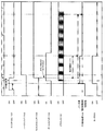
- FIG. 12 is an operation chart of the vehicle door drive device 1100 when the side door 101 in the fully closed state according to the present embodiment is opened.
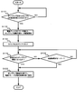
- FIG. 13 is a flowchart showing the processing procedure of the pop-up opening operation according to the present embodiment.
- the processing procedure is processing executed by the CPU 302 of the control device 301. Therefore, control of the process is performed by the CPU 302 reading a program for performing the process shown in FIG. 13 stored in the ROM 303 and executing the program.
- the area A indicates that the side door 101 is fully closed
- the area B indicates that the side door 101 is half
- the area C indicates that the side door 101 is in the pop-up opening state
- the area D indicates that the side door 101 can be opened and closed manually (normal state)
- the area E indicates that the side door 101 is fully open.
- the pop-up opening operation is performed at a constant pop-up opening degree when the pop-up command is input without being limited to the input place and the input method.
- step S131 the control device 301 determines whether the switch 106 or the switch 107 has been pressed by the user for a sufficient time (an ON determination time) as an input of a pop-up instruction. That is, based on the pop-up command information input from switch 106 or switch 107, control device 301 determines whether or not the user has pressed the switch for the ON determination time or more, and presses the switch for the ON determination time or more. If it judges, it will progress to step S132. On the other hand, if the pressing time of the user to the switches 106 and 107 is less than the ON determination time, the control device 301 repeats step S131 until it is determined that the user presses the switches 106 and 107 for the ON determination time or more.
- a sufficient time an ON determination time
- step S132 the control device 301 switches the door holding device 108 in the holding state to the free state and controls the drive circuit 308 to start driving the motor 309 for pop-up opening operation. That is, the control device 301 controls the drive circuit 307 to stop the energization of the electromagnetic brake 204 which is energized to generate the maximum holding torque, and brings the electromagnetic brake 204 into the free state. At the same time, the control device 301 drives the motor 309 to cause the pop-up opening operation to the set pop-up opening degree ⁇ . At this time, although the motor 309 is driven, the side door 101 has not moved automatically yet by the action of the latch device 109. In addition, the control device 301 controls the drive circuit 306 to drive the latch 109 and rotate the latch located at the full latch position.
- the pole switch 1104 is turned on with the driving of the latch, and the door sensor 1101 is also turned on.
- the fully closed state A is shifted to the half door state B.
- the door sensor 1101 transmits a pulse signal to the control device 301 according to the movement of the side door 101.
- the control device 301 causes the RAM 304 to accumulate the number of pulses in accordance with the pulse signal received from the door sensor 1101. Therefore, the RAM 304 functions as a counter of the number of pulses used when calculating the angle of the side door 101.
- the control device 301 can calculate the angle of the side door 101 based on the number of pulses accumulated in the counter.
- controlling the electromagnetic brake 204 in the free state and simultaneously starting the driving of the motor 309 are simultaneously performed, but the present invention is not limited to this. What is important in this embodiment is that the electromagnetic brake 204 is in a free state before the side door 101 actually starts to move automatically by the pop-up opening operation. Therefore, in FIG. 12, the electromagnetic brake 204 may be brought into the free state before shifting to the pop-up opening operation area C. If this is realized, the transition of the electromagnetic brake 204 (door holding device 108) to the free state may be different from the timing at which the motor 309 is turned on.
- step S133 the control device 301 resets the counter and the timer 1105 when the full latch switch 1103 is turned on by the rotation of the latch after becoming a half door state. Conversely, from this point in time, the control device 301 starts aging with the timer 1105 and also starts detecting the angle of the side door 101.
- the half door state B when the half switch 1102 is turned on by the rotation of the latch, the latch is positioned more open than the half latch position in a state where the latch of the latch device 109 is released. Then, the half door state B is shifted to the pop open operation state C. Since the motor 309 for moving the rack 202 (side door 101) is already driven, the side door 101 opens automatically. At this time, since the electromagnetic brake 204 is in the free state, the holding mechanism of the side door 101 is in the released state. Therefore, the pop-up opening operation can be performed in a state where the holding force for holding the side door 101 is not generated.
- the door sensor 1101 transmits a pulse signal to the control device 301.
- the control device 301 receives a pulse signal from the door sensor 1101
- the control device 301 increases the number of pulses counted by the counter configured in the RAM 304.
- the timer 1105 measures the elapsed time during the pop-up opening operation.
- the control device 301 determines whether the current opening degree of the side door 101 has become the pop-up opening degree ⁇ . That is, the control device 301 calculates the current opening degree of the side door 101 based on the total number of pulses transmitted from the door sensor 1101 accumulated in the counter, and compares it with the set pop-up opening degree ⁇ . If the calculated current opening degree is smaller than the set pop-up opening degree ⁇ , the control device 301 determines that the side door 101 is not yet positioned at the pop-up door position, and repeats step S135. On the other hand, when the calculated current opening degree matches the set pop-up opening degree ⁇ , the control device 301 determines that the side door 101 has reached the pop-up door position, and proceeds to step S136.
- control device 301 refers to the timer 1105 and determines whether the elapsed time has exceeded a predetermined time. If the elapsed time has not exceeded the predetermined time, the control device 301 returns to step S134. On the other hand, when the elapsed time exceeds the predetermined time, the control device 301 proceeds to step S136.
- step S135 the control device 301 controls the drive circuit 308 to stop the drive of the motor 309 to stop the pop-up opening operation, and switches the electromagnetic brake 204 from the free state to the voltage control state. Specifically, when the motor 309 is stopped, the control device 301 determines whether the side door 101 is currently moving or not based on a pulse signal from the door sensor 1101. If it is determined that the side door 101 is stopped as a result of detection by the door sensor 1101, the control device 301 controls the drive circuit 307 to drive the electromagnetic brake 204 to generate a predetermined holding force. As a result, the electromagnetic brake 204 is in the holding state, and the side door 101 is held by the holding force at the pop-up door position.
- the control device 301 does not generate holding power by the electromagnetic brake 204 and maintains the free state. .
- the side door 101 is not held at the pop-up door position, and can move as it is.
- the user manually operates the side door 101 during the pop-up opening operation, in addition to the opening operation of the side door 101 by the drive of the motor 309.
- opening There is a case of opening. In this case, the side door 101 is automatically opened by the drive of the motor 309, but an operation force for manually opening the side door 101 is also applied. Therefore, even if the pop-up opening operation is completed, the side door 101 is moved by the manual operation force.
- the door sensor 1101 is used to determine whether the side door 101 is moving after the end of the pop-up opening operation.
- the door sensor 1101 transmits a pulse to the control device 301.
- the door sensor 1101 does not transmit a pulse to the control device 301. That is, focusing on the pulse transmitted from the door sensor 1101 to the control device 301, it indicates that the side door 101 is moving if the pulse is output, and the side door 101 is stopped if the pulse is not output. Indicates that.
- the side door 101 is moved by determining whether the pulse is received or not received from the door sensor 1101 in the voltage control state after the end of the pop-up opening operation in the control device 301. It is determined whether the That is, in the voltage control state, if a pulse is output from the door sensor 1101, the control device 301 determines that the side door 101 is moving, and controls the door holding device 108 to be in the free state. Further, in the voltage control state, the controller 301 determines that the side door 101 is stopped if the pulse is not output from the door sensor 1101, and controls the door holding device 108 so as to be in the holding state.
- the door sensor 1101 has a function of detecting the opening degree of the side door 101 and a function of detecting whether the side door 101 is moving.
- the pop-up opening operation ends.
- the normal state D is entered.
- the door holding device 08 is in the voltage control state. Therefore, in the normal state D, when it is determined by the door sensor 1101 that the side door 101 is moving, the control device 301 controls the door holding device 108 (electromagnetic brake 204) so as to be in the free state. Further, in the normal state D, when judging that the side door 101 is stopped by the door sensor 1101, the control device 301 controls the door holding device 108 (electromagnetic brake 204) so as to be in the holding state.
- the door sensor 1101 indicates that the side door 101 is moved by the user.
- the door holding device 108 detects that the door holding device 108 is released, the state is shifted to the free state.
- the state D when the side door 101 is manually opened and moved and the side door is stopped by the user's intention, when the door sensor 1101 detects the stop, the free state is changed to the holding state. In transition, the door holding device 108 holds the side door 101 at that position.
- the door holding device 108 when the pop-up instruction is input from the user, the door holding device 108 is forcibly changed from the holding state to the free state before the side door 101 becomes movable. Therefore, when the side door 101 is automatically opened by the pop-up opening operation, it is possible not to generate a holding force (holding torque) for holding the side door 101. Therefore, the pop-up opening operation can be performed smoothly.
- the door holding device 108 is put in the voltage control state, so that the presence or absence of the generation of the holding power of the side door 101 is appropriately made Can be selected. Also, even after the pop-up opening operation is finished, the door holding device 108 is put in the voltage control state, so when the user stops the movement of the side door 101 when the side door 101 is manually opened, The side door 101 can be held by the holding torque of the door holding device 108. In addition, when the user stops at a predetermined position between the pop-up door position and the fully open state and the user moves the side door 101 held by the holding force at that position, the holding force is automatically canceled. Can. Therefore, the user can manually operate the side door 101 without feeling stress due to holding power. As described above, the opening operation of the side door 101 from the fully closed state can be dramatically improved while being basically manual.
- an unintended pulse may be output from the door sensor 1101 to the control device 301 due to the shaking of the vehicle 100 or the like. If there is such an unintended pulse, even if the side door 101 does not actually perform the pop-up opening operation, the counter accumulates the count for the calculation of the opening degree, and the calculated opening degree is actually It deviates from the opening. However, in the present embodiment, in step S133, in the pop-up opening operation, before the side door 101 starts to open from the fully closed state, the counter accumulating the pulse number from the door sensor 1101 is reset.
- the pulse generated unexpectedly can be removed, and the side door related to the pop-up opening operation
- the number of pulses for the movement of 101 can be extracted. Therefore, the accuracy of the opening degree calculated based on the detection result of the door sensor 1101 can be improved. That is, it is possible to set the opening degree at the end of the pop-up opening operation to the pop-up opening degree ⁇ .
- the elapsed time of the pop-up opening operation is measured by the timer 1105, and when the elapsed time exceeds the predetermined time, the process proceeds to step S136 forcibly to end the pop-up operation. Transition to the state. Therefore, the door holding device 108 is changed from the free state to the holding state even when the control device 301 recognizes that the pop-up opening operation is in progress although the pop-up opening operation is not actually performed. can do. For example, when the weather strip is stuck to the side door 101 due to freezing when the vehicle environment is low temperature, the motor 309 may be driven, but the side door 101 may not move due to the freezing.
- control device 301 executes an algorithm for performing the pop-up opening operation by the input of the pop-up command, until the opening degree of the side door 101 becomes the set pop-up opening degree ⁇ according to the detection result of the door sensor 1101
- the door holding device 108 is controlled to be free.
- the side door 101 is not held by the holding force of the door holding device 108.
- the side door 101 is not held by the holding force and is in a free state, so the side door 101 can be opened when the user does not intend There is sex.
- the door holding device 108 is forcibly shifted to the voltage control state. If the side door 101 is not moving due to the freezing, the side door 101 is stopped at the time of transition to the voltage control state, and the control device 301 controls the door holding device 108 in the holding state. Therefore, since the side door 101 is held by the holding force of the door holding device 108, the side door 101 does not move freely even if the freezing is eliminated and the sticking of the weather strip is also eliminated. , Is held in that position. Therefore, it is possible to prevent the side door 101 from moving unexpectedly.
- the holding force of the door holding device 108 is variable according to the inclination of the vehicle 100.
- the user manually operates the side door 101 and opens it in the direction 1402 in the vehicle 100 in which the door hand direction is inclined to the lower side of the slope 1401 on the slope 1401 of the inclination angle ⁇ .
- the side door 101 tries to open by its own weight. That is, when the vehicle 100 is inclined as shown in FIG. 14, the door hand direction of the side door 101 is directed to the gravity direction side, and therefore, the side door 101 tries to open by hand. Therefore, in order to suppress the door behavior by this dead weight, the operating force burden to a user arises.
- the door holding device 108 when the vehicle 100 is inclined such that the side door 101 tries to open by its own weight on the side of the side door 101 in the self-handling direction, the door holding device 108 generates a holding force. 101 is made to move by dragging the holding force. Therefore, the influence of the weight of the side door 101 caused by the inclination can be offset or reduced by the holding force, and the operation force at the time of opening the side door 101 from the inside of the inclined vehicle 100 can be reduced. it can.
- FIG. 15 is a block diagram showing a schematic configuration of a control system in a vehicle door drive device 1500 according to the present embodiment.
- Vehicle door drive device 1500 includes switch 1501 operated in conjunction with inside handle 105, door holding device 108, drive circuit 307, motor 309, drive circuit 308, wireless signal transmission / reception unit 310, and vehicle 100.
- a tilt sensor 801 for detecting the tilt angle ⁇ , a door sensor 1101 for measuring the opening degree of the side door 101, and a control device 301 are provided.
- the ROM 303 stores the control program shown in FIG.
- a switch 1501 is provided on the inside handle 105, detects that the user manually opens the inside handle 105, and indicates open operation command information indicating that the inside handle 105 is pulled by the user and manually opened. Are sent to the control device 301.
- the switch 1501 is configured to operate when the inside handle 105 is pulled by a predetermined amount.
- FIG. 16 is a flowchart showing a processing procedure of changing the holding force according to the inclination of the vehicle when the side door according to the present embodiment is opened from the inside of the vehicle.
- the processing procedure is processing executed by the CPU 302 of the control device 301. Therefore, control of the process is performed by the CPU 302 reading a program for performing the process shown in FIG. 16 stored in the ROM 303 and executing the program.
- step S1601 the control device 301 determines whether an open operation instruction has been input by the user via the inside handle 105.
- the switch 1501 detects an opening operation of the inside handle 105 by the user, and transmits opening operation instruction information to the control device 301.
- the control device 301 determines that the user has performed an opening operation by the inside handle 105, and proceeds to step S1602.
- the control device 301 repeats step S1601 until the open operation command information is received.
- step S1602 the control device 301 acquires inclination angle information from the inclination sensor 801, and acquires the inclination angle ⁇ of the side door 101 of the vehicle 100 in the hand direction.
- step S1603 based on the inclination angle ⁇ acquired in step S1602, the control device 301 determines whether or not the door hand direction of the side door 101 to be operated is directed to the lower side of the vehicle 100. to decide. That is, it is determined whether or not the vehicle 100 is inclined such that the side door 101 opens in the door self-direction by its own weight.
- the inclination angle ⁇ is defined such that the inclination angle when the side door 101 faces the downward side of the slope 1401 is an acute angle.
- step S1602 when the inclination angle ⁇ acquired in step S1602 is 0 ° ⁇ inclination angle ⁇ ⁇ 90 °, the control device 301 causes the door 100 of the side door 101 to face the lower side of the vehicle 100. It is determined that the vehicle is inclined, and the process proceeds to step S1604. On the other hand, when the inclination angle ⁇ acquired in step S1602 is 90 ° ⁇ the inclination angle ⁇ ⁇ 180 °, the control device 301 causes the door 100 of the side door 101 to face the lower side of the vehicle 100. It is determined that the vehicle is not inclined as described above, and the process proceeds to step S1606.
- the control device 301 inclines so that the vehicle 100 is facing the lower side of the vehicle 100. It is determined that there is not, and the process proceeds to step S1606.
- the inclination sensor 801 can detect the inclination angle ⁇ of the vehicle 100 and can detect whether or not the door hand direction of the side door 101 is inclined so as to face the lower side of the vehicle 100.
- step S1604 the control device 301 determines the holding force (holding torque) to be generated by the door holding device 108 in accordance with the inclination angle ⁇ acquired in step S1602.
- the holding force holding torque
- the side door 101 is held by the holding force when the fully closed side door 101 is opened from the inside.
- the user opens the side door 101 so as to drag the holding force. Therefore, in the case of the said inclination, it can reduce that the side door 101 runs freely.
- the holding force is determined such that the operation feeling of the user of the above is equivalent to the above-described operation feeling when the vehicle 100 is not inclined (flat). Therefore, also in the above-mentioned inclination, the user can open the side door 101 in the fully closed state with the same operation force as that in the flat state.
- the holding force by the door holding device 108 may be set so as to cancel the force (weight) of the side door 101 toward the outside of the vehicle 100 due to its own weight.
- the inclination (inclination angle ⁇ ) of the vehicle 100 and the force to open the side door 101 by the weight of the side door 101 may be made into a function. If the above force is offset by the holding force generated by the door holding device 108, even if the vehicle 100 is inclined such that the door hand direction of the side door 101 is directed to the lower side of the vehicle 100, the operation force by the user is flat. It can be equal to time. Therefore, the control device calculates the above-mentioned force corresponding to the inclination angle acquired in step 1602 with reference to the above-mentioned function, and sets the holding force to be realized to the value of the force.
- the side door 101 may be held with a predetermined holding force.
- the door holding device 108 may hold the side door 101 with a predetermined holding force (may be a constant force).
- the inclination angle ⁇ may be associated with the holding torque of the door holding device 108 by a table so that the holding force increases as the inclination angle ⁇ increases.
- the control device 301 may extract the holding force corresponding to the detected inclination angle ⁇ with reference to the table.
- step S1605 the control device 301 controls the drive circuit 307 to cause the electromagnetic brake 204 to generate the holding force (holding torque) determined in step S1604. That is, control device 301 causes the electromagnetic brake to be energized so that the holding torque determined in step S1604 is generated.
- the door holding device 108 holds the fully closed side door 101 with an appropriate holding force.
- step S1606 the control device 301 determines, based on the pulse signal received from the door sensor 1101, whether or not the side door 101 has been fully opened. That is, the control device 301 calculates the current opening degree of the side door 101 based on the pulse signal transmitted from the pulse sensor 1101, and sets the full opening degree set as the opening degree of the fully open state of the side door 101. Compare. If it is determined by the comparison that the side door 101 is fully open, the control device 301 controls the drive circuit 307 to stop the energization of the electromagnetic brake 204, cancels the holding torque, and ends the process. Do.
- step S1604 step S1606 is repeated while maintaining the holding force determined in step S1604.
- step S1607 the control device 301 controls the drive circuit 307 to control the electromagnetic brake 204 so as not to generate the holding torque.
- the vehicle 100 is either not inclined or is inclined such that the direction of the handedness of the side door 101 faces the upper side of the vehicle 100. That is, it is estimated that the side door 101 is not opened by its own weight in the door self direction. Therefore, in the present embodiment, in this case, the door holding device 108 is controlled so as not to generate the holding force for producing the above-mentioned drag feeling.
- the user when the vehicle 100 is inclined so that the side door 101 opens in the door self direction by its own weight, the user holds the door 100 when manually opening the side door 101 from the inside of the vehicle 100 by the user.
- the device 108 generates a holding force for holding the side door 101. Therefore, it is possible to brake that the side door 101 of the vehicle 100 which is thus inclined can move freely in the downward direction of the slope 1401 by the weight applied to itself. That is, in the above-described inclined vehicle 100, the side door 101 can be prevented or reduced from opening by itself in the door self direction by its own weight.
- the holding force reduces the force to open the side door 101 in the door self direction by its own weight, it is possible to prevent or reduce the opening of the side door 101 at an unintended speed. Further, since the side door 101 is held by the holding force generated by the door holding device 108, a drag feeling can be given when the user operates, and as a result, the feeling of the opening operation of the side door 101 can be obtained. It can be approached flat.
- the tilt angle of the vehicle 100 is detected, and the door holding device 108 is generated so as to offset the force to open the side door 101 in the door hand direction by the dead weight based on the tilt angle.
- the holding force is determined. Therefore, the holding force can be applied to cancel the force caused by the inclination, and the feeling of the opening operation of the side door 101 can be made equal to that in the flat state.
- the holding force for preventing or reducing the side door 101 from being freehanded is executed by the electromagnetic brake 204 at the time of the inclination
- the present invention is not limited to this.
- the holding force may be controlled by a damper mechanism using oil.
- a damper mechanism is provided to control the resistance of the pivoting of the lever 205 by the damping force of the damper.
- the viscosity is changed to control the damping force.
- the damping may be controlled using a magnetic fluid.
- Reference Signs List 100 vehicle 101 side door 104 inside handle 105 outside handle 106, 107 switch 108 door holding device 202 rack 203 pinion 204 electromagnetic brake 205 lever 300, 800, 1100, 1500 vehicle door drive device 301 control device 307, 308 drive circuit 309 motor 311 pulse sensor 801 tilt sensor 1101 door sensor
Landscapes
- Engineering & Computer Science (AREA)
- Computer Networks & Wireless Communication (AREA)
- Mechanical Engineering (AREA)
- Power-Operated Mechanisms For Wings (AREA)
Abstract
L'invention concerne un dispositif d'entraînement de portière de véhicule et un procédé d'entraînement de portière de véhicule qui sont susceptibles de réduire la force opérationnelle requise lors de l'ouverture manuelle d'une portière pour un véhicule dont une portière de véhicule (par exemple, une portière latérale, un hayon arrière, un capot de coffre, ou similaires) peut être ouverte manuellement. Dans un mode de réalisation de la présente invention, une commande pour ouvrir automatiquement une portière latérale (101) dans un état complètement fermé d'une quantité prescrite qui n'est pas un état complètement ouvert est saisie (étape S61), et un angle d'ouverture (θ) est déterminé en fonction de si la commande a été saisie avec un interrupteur (106) externe à un véhicule (100) ou avec un interrupteur interne (107) (étapes S62-S64). Ensuite, une opération d'ouverture est effectuée conformément à l'angle déterminé (θ) (étapes S65, S66).
Priority Applications (3)
| Application Number | Priority Date | Filing Date | Title |
|---|---|---|---|
| CN201480037431.3A CN105358785B (zh) | 2013-07-04 | 2014-06-20 | 车门驱动装置 |
| EP14819950.8A EP3017984B1 (fr) | 2013-07-04 | 2014-06-20 | Dispositif d'entraînement de portière de véhicule |
| US14/902,262 US20160369551A1 (en) | 2013-07-04 | 2014-06-20 | Vehicle door drive apparatus |
Applications Claiming Priority (6)
| Application Number | Priority Date | Filing Date | Title |
|---|---|---|---|
| JP2013140865A JP6197417B2 (ja) | 2013-07-04 | 2013-07-04 | 車両ドア駆動装置、および車両ドア駆動方法 |
| JP2013-140865 | 2013-07-04 | ||
| JP2013140864A JP6197416B2 (ja) | 2013-07-04 | 2013-07-04 | 車両ドア駆動装置、および車両ドア駆動方法 |
| JP2013140863A JP6197415B2 (ja) | 2013-07-04 | 2013-07-04 | 車両ドア駆動装置、および車両ドア駆動方法 |
| JP2013-140864 | 2013-07-04 | ||
| JP2013-140863 | 2013-07-04 |
Publications (1)
| Publication Number | Publication Date |
|---|---|
| WO2015001749A1 true WO2015001749A1 (fr) | 2015-01-08 |
Family
ID=52143352
Family Applications (1)
| Application Number | Title | Priority Date | Filing Date |
|---|---|---|---|
| PCT/JP2014/003316 Ceased WO2015001749A1 (fr) | 2013-07-04 | 2014-06-20 | Dispositif d'entraînement de portière de véhicule |
Country Status (4)
| Country | Link |
|---|---|
| US (1) | US20160369551A1 (fr) |
| EP (1) | EP3017984B1 (fr) |
| CN (1) | CN105358785B (fr) |
| WO (1) | WO2015001749A1 (fr) |
Cited By (1)
| Publication number | Priority date | Publication date | Assignee | Title |
|---|---|---|---|---|
| CN115354936A (zh) * | 2022-05-30 | 2022-11-18 | 东风汽车集团股份有限公司 | 一种电动尾门控制方法及系统 |
Families Citing this family (27)
| Publication number | Priority date | Publication date | Assignee | Title |
|---|---|---|---|---|
| JP2015086529A (ja) * | 2013-10-29 | 2015-05-07 | アイシン精機株式会社 | 車両用ドアのポップアップ機構 |
| CN105882603A (zh) * | 2015-10-30 | 2016-08-24 | 乐卡汽车智能科技(北京)有限公司 | 信息处理方法及系统 |
| RU2704938C1 (ru) * | 2016-03-15 | 2019-10-31 | Малтиматик Инк. | Система подачи двери и способ ее работы |
| DE102016213525A1 (de) * | 2016-07-22 | 2018-02-08 | Brose Fahrzeugteile Gmbh & Co. Kommanditgesellschaft, Bamberg | Vorrichtung zum fremdkraftbetätigten und manuellen Verstellen eines Fahrzeugteils |
| JP6729332B2 (ja) * | 2016-12-05 | 2020-07-22 | 株式会社デンソー | 障害物検出装置 |
| CN109594880B (zh) * | 2017-09-30 | 2020-08-07 | 比亚迪股份有限公司 | 控制车辆后备箱的方法和装置、存储介质和车辆 |
| JP6629810B2 (ja) * | 2017-10-06 | 2020-01-15 | 株式会社Subaru | ドア制御装置 |
| DE102017125433A1 (de) * | 2017-10-30 | 2019-05-02 | Brose Fahrzeugteile Gmbh & Co. Kommanditgesellschaft, Bamberg | Baugruppe zum Verstellen eines Verstellelements relativ zu einem feststehenden Abschnitt eines Fahrzeugs |
| US10669757B2 (en) | 2017-11-30 | 2020-06-02 | Fca Us Llc | Variable position vehicle hood stay device |
| US10633893B2 (en) | 2018-01-02 | 2020-04-28 | Ford Global Technologies, Llc | Door actuator with retraction device |
| CN110853187A (zh) * | 2018-07-27 | 2020-02-28 | 比亚迪股份有限公司 | 解锁车门的方法和装置、存储介质和车辆 |
| JP7286945B2 (ja) * | 2018-10-26 | 2023-06-06 | 株式会社アイシン | 車両用扉の障害物認識装置および車両用の障害物認識機能付扉 |
| EP3918169B1 (fr) * | 2019-02-01 | 2025-08-20 | Brose Fahrzeugteile SE & Co. Kommanditgesellschaft, Bamberg | Dispositif d'entraînement de portière pouvant être commandé pour détecter une action d'utilisateur sur une portière de véhicule |
| KR102715803B1 (ko) * | 2019-02-19 | 2024-10-10 | 현대자동차 주식회사 | 차량용 전동식 도어 래치 |
| DE102019119823A1 (de) * | 2019-07-23 | 2021-01-28 | Kiekert Aktiengesellschaft | Aufstellvorrichtung für ein Kraftfahrzeugtürelement |
| US11814891B2 (en) * | 2020-03-24 | 2023-11-14 | Magna Closures Inc. | Door system with door presenter control |
| CN112576116A (zh) * | 2020-12-11 | 2021-03-30 | 芜湖汽车前瞻技术研究院有限公司 | 汽车全息门把手系统及其控制方法 |
| DE102021209108A1 (de) | 2021-08-19 | 2023-02-23 | Vitesco Technologies GmbH | Vorrichtung und Verfahren zum Schließen einer Fahrzeugklappe eines Fahrzeugs |
| CN114183032A (zh) * | 2021-12-02 | 2022-03-15 | 重庆金康赛力斯新能源汽车设计院有限公司 | 一种车门的控制方法和系统 |
| CN114274897B (zh) * | 2021-12-30 | 2023-09-26 | 奇瑞汽车股份有限公司 | 隐藏式门把手的控制方法及车辆 |
| CN114439343B (zh) * | 2022-02-24 | 2023-06-27 | 重庆长安汽车股份有限公司 | 一种电动侧开门的电驱动器、安装结构及汽车 |
| CN114809833B (zh) * | 2022-03-25 | 2024-06-04 | 北京宾理信息科技有限公司 | 开启车门的控制方法、车门控制装置及车门控制系统 |
| CN114778883B (zh) * | 2022-03-28 | 2024-04-12 | 上海电气集团股份有限公司 | 列车车门限位开关的检测方法、系统、设备及介质 |
| CN114622783A (zh) * | 2022-03-31 | 2022-06-14 | 孙鹏 | 一种用于汽车的开门防碰撞系统 |
| CN115898168B (zh) * | 2022-10-31 | 2025-07-08 | 东风汽车集团股份有限公司 | 汽车电动门锁的控制方法、装置、设备及存储介质 |
| CN116876945A (zh) * | 2023-08-09 | 2023-10-13 | 阿维塔科技(重庆)有限公司 | 车门悬停控制方法、装置及电子设备 |
| CN120425975A (zh) * | 2025-03-21 | 2025-08-05 | 浙江极氪智能科技有限公司 | 一种车辆控制方法、车辆、电子设备及存储介质 |
Citations (5)
| Publication number | Priority date | Publication date | Assignee | Title |
|---|---|---|---|---|
| JPH11170867A (ja) * | 1997-12-12 | 1999-06-29 | Mitsuba Corp | 車両用ドアの開放方法および装置 |
| JP2005280393A (ja) | 2004-03-26 | 2005-10-13 | Aisin Seiki Co Ltd | 車両用ドア制御装置 |
| JP2006316497A (ja) * | 2005-05-12 | 2006-11-24 | Honda Motor Co Ltd | ドア開閉制御装置 |
| JP2009221760A (ja) * | 2008-03-17 | 2009-10-01 | Tokai Rika Co Ltd | 車両用ドア開閉制御装置 |
| JP2011106187A (ja) * | 2009-11-18 | 2011-06-02 | Aisin Seiki Co Ltd | 車両用ドア制御装置 |
Family Cites Families (8)
| Publication number | Priority date | Publication date | Assignee | Title |
|---|---|---|---|---|
| JP3067095B2 (ja) * | 1996-06-07 | 2000-07-17 | 本田技研工業株式会社 | スライドドアの開閉制御装置 |
| US6498970B2 (en) * | 2001-04-17 | 2002-12-24 | Koninklijke Phillips Electronics N.V. | Automatic access to an automobile via biometrics |
| US20050085972A1 (en) * | 2003-10-16 | 2005-04-21 | International Business Machines Corporation | Door opening limit control system |
| JP4555697B2 (ja) * | 2005-01-27 | 2010-10-06 | アイシン精機株式会社 | 開閉体制御装置 |
| US7688179B2 (en) * | 2005-12-12 | 2010-03-30 | Denso International America, Inc. | Hands-free vehicle door opener |
| DE102007062473A1 (de) * | 2007-12-20 | 2009-07-02 | Technische Universität München | Tür, insbesondere Fahrzeugtür, mit wenigstens zwei kinematischen Freiheitsgraden und Verfahren zu ihrer Betätigung |
| JP5625178B2 (ja) * | 2010-09-22 | 2014-11-19 | トヨタ車体株式会社 | 乗降口開閉装置を備えた車両 |
| DE102011119579A1 (de) * | 2011-11-26 | 2013-05-29 | Kiekert Aktiengesellschaft | Vorrichtung zur elektromotorischen Betätigung einer Tür |
-
2014
- 2014-06-20 WO PCT/JP2014/003316 patent/WO2015001749A1/fr not_active Ceased
- 2014-06-20 EP EP14819950.8A patent/EP3017984B1/fr active Active
- 2014-06-20 US US14/902,262 patent/US20160369551A1/en not_active Abandoned
- 2014-06-20 CN CN201480037431.3A patent/CN105358785B/zh active Active
Patent Citations (5)
| Publication number | Priority date | Publication date | Assignee | Title |
|---|---|---|---|---|
| JPH11170867A (ja) * | 1997-12-12 | 1999-06-29 | Mitsuba Corp | 車両用ドアの開放方法および装置 |
| JP2005280393A (ja) | 2004-03-26 | 2005-10-13 | Aisin Seiki Co Ltd | 車両用ドア制御装置 |
| JP2006316497A (ja) * | 2005-05-12 | 2006-11-24 | Honda Motor Co Ltd | ドア開閉制御装置 |
| JP2009221760A (ja) * | 2008-03-17 | 2009-10-01 | Tokai Rika Co Ltd | 車両用ドア開閉制御装置 |
| JP2011106187A (ja) * | 2009-11-18 | 2011-06-02 | Aisin Seiki Co Ltd | 車両用ドア制御装置 |
Non-Patent Citations (1)
| Title |
|---|
| See also references of EP3017984A4 |
Cited By (1)
| Publication number | Priority date | Publication date | Assignee | Title |
|---|---|---|---|---|
| CN115354936A (zh) * | 2022-05-30 | 2022-11-18 | 东风汽车集团股份有限公司 | 一种电动尾门控制方法及系统 |
Also Published As
| Publication number | Publication date |
|---|---|
| EP3017984A1 (fr) | 2016-05-11 |
| CN105358785B (zh) | 2017-09-08 |
| US20160369551A1 (en) | 2016-12-22 |
| EP3017984B1 (fr) | 2021-12-01 |
| EP3017984A4 (fr) | 2016-07-06 |
| CN105358785A (zh) | 2016-02-24 |
Similar Documents
| Publication | Publication Date | Title |
|---|---|---|
| WO2015001749A1 (fr) | Dispositif d'entraînement de portière de véhicule | |
| JP6197417B2 (ja) | 車両ドア駆動装置、および車両ドア駆動方法 | |
| US7937893B2 (en) | Intuitive handle switch operation for power sliding doors | |
| CN105408709B (zh) | 冰箱 | |
| CN104456646B (zh) | 抽屉式微波炉及其开关门控制方法 | |
| CN102470735B (zh) | 用于识别翻盖驱动装置中接合器的触发的方法和装置 | |
| CN110958971B (zh) | 辅助行李厢门打开/关闭的装置和方法 | |
| JP2009221652A (ja) | 車両用ドアの電動開閉装置 | |
| KR20180010997A (ko) | 차량 부품을 전동 및 수동으로 조정하기 위한 장치 | |
| JP2009108605A (ja) | 車両用開閉体制御装置 | |
| JP6197415B2 (ja) | 車両ドア駆動装置、および車両ドア駆動方法 | |
| JP2019090246A (ja) | 車両開閉体制御装置および方法 | |
| JP2019001380A (ja) | 車両ドアの非接触開放装置 | |
| JP6197416B2 (ja) | 車両ドア駆動装置、および車両ドア駆動方法 | |
| CN106812410B (zh) | 用于车辆的开关体控制装置 | |
| JP2006144467A (ja) | 車両用スライドドアの開閉制御装置 | |
| US20090302637A1 (en) | Vehicle door opening device | |
| JP5669750B2 (ja) | 車両ウイングの閉動作の制御方法及び対応する車両の閉システム | |
| JP2017149212A (ja) | ドア接触防止制御システム及びコンピュータプログラム | |
| CN115726655B (zh) | 电动滑移门的控制方法、装置、车辆及可读存储介质 | |
| JP2019105046A (ja) | 車両用ドア制御システム | |
| JP4725205B2 (ja) | 車両ドア制御装置および制御方法 | |
| JP2004346706A (ja) | 車両用ドア開閉装置 | |
| WO2012125130A1 (fr) | Dispositif de déplacement de portière de véhicule | |
| JP6207126B2 (ja) | ドア開閉装置 |
Legal Events
| Date | Code | Title | Description |
|---|---|---|---|
| WWE | Wipo information: entry into national phase |
Ref document number: 201480037431.3 Country of ref document: CN |
|
| 121 | Ep: the epo has been informed by wipo that ep was designated in this application |
Ref document number: 14819950 Country of ref document: EP Kind code of ref document: A1 |
|
| WWE | Wipo information: entry into national phase |
Ref document number: 14902262 Country of ref document: US |
|
| NENP | Non-entry into the national phase |
Ref country code: DE |
|
| WWE | Wipo information: entry into national phase |
Ref document number: 2014819950 Country of ref document: EP |