WO2014066879A2 - Context awareness for smart televisions - Google Patents
Context awareness for smart televisions Download PDFInfo
- Publication number
- WO2014066879A2 WO2014066879A2 PCT/US2013/067024 US2013067024W WO2014066879A2 WO 2014066879 A2 WO2014066879 A2 WO 2014066879A2 US 2013067024 W US2013067024 W US 2013067024W WO 2014066879 A2 WO2014066879 A2 WO 2014066879A2
- Authority
- WO
- WIPO (PCT)
- Prior art keywords
- context
- television
- user
- smart
- context information
- Prior art date
- Legal status (The legal status is an assumption and is not a legal conclusion. Google has not performed a legal analysis and makes no representation as to the accuracy of the status listed.)
- Ceased
Links
Classifications
-
- H—ELECTRICITY
- H04—ELECTRIC COMMUNICATION TECHNIQUE
- H04N—PICTORIAL COMMUNICATION, e.g. TELEVISION
- H04N21/00—Selective content distribution, e.g. interactive television or video on demand [VOD]
- H04N21/40—Client devices specifically adapted for the reception of or interaction with content, e.g. set-top-box [STB]; Operations thereof
- H04N21/45—Management operations performed by the client for facilitating the reception of or the interaction with the content or administrating data related to the end-user or to the client device itself, e.g. learning user preferences for recommending movies, resolving scheduling conflicts
- H04N21/466—Learning process for intelligent management, e.g. learning user preferences for recommending movies
- H04N21/4667—Processing of monitored end-user data, e.g. trend analysis based on the log file of viewer selections
-
- H—ELECTRICITY
- H04—ELECTRIC COMMUNICATION TECHNIQUE
- H04N—PICTORIAL COMMUNICATION, e.g. TELEVISION
- H04N21/00—Selective content distribution, e.g. interactive television or video on demand [VOD]
- H04N21/40—Client devices specifically adapted for the reception of or interaction with content, e.g. set-top-box [STB]; Operations thereof
- H04N21/43—Processing of content or additional data, e.g. demultiplexing additional data from a digital video stream; Elementary client operations, e.g. monitoring of home network or synchronising decoder's clock; Client middleware
- H04N21/442—Monitoring of processes or resources, e.g. detecting the failure of a recording device, monitoring the downstream bandwidth, the number of times a movie has been viewed, the storage space available from the internal hard disk
- H04N21/44213—Monitoring of end-user related data
- H04N21/44222—Analytics of user selections, e.g. selection of programs or purchase activity
- H04N21/44224—Monitoring of user activity on external systems, e.g. Internet browsing
- H04N21/44226—Monitoring of user activity on external systems, e.g. Internet browsing on social networks
-
- H—ELECTRICITY
- H04—ELECTRIC COMMUNICATION TECHNIQUE
- H04N—PICTORIAL COMMUNICATION, e.g. TELEVISION
- H04N21/00—Selective content distribution, e.g. interactive television or video on demand [VOD]
- H04N21/40—Client devices specifically adapted for the reception of or interaction with content, e.g. set-top-box [STB]; Operations thereof
- H04N21/41—Structure of client; Structure of client peripherals
- H04N21/422—Input-only peripherals, i.e. input devices connected to specially adapted client devices, e.g. global positioning system [GPS]
- H04N21/42202—Input-only peripherals, i.e. input devices connected to specially adapted client devices, e.g. global positioning system [GPS] environmental sensors, e.g. for detecting temperature, luminosity, pressure, earthquakes
-
- H—ELECTRICITY
- H04—ELECTRIC COMMUNICATION TECHNIQUE
- H04N—PICTORIAL COMMUNICATION, e.g. TELEVISION
- H04N21/00—Selective content distribution, e.g. interactive television or video on demand [VOD]
- H04N21/40—Client devices specifically adapted for the reception of or interaction with content, e.g. set-top-box [STB]; Operations thereof
- H04N21/41—Structure of client; Structure of client peripherals
- H04N21/422—Input-only peripherals, i.e. input devices connected to specially adapted client devices, e.g. global positioning system [GPS]
- H04N21/42203—Input-only peripherals, i.e. input devices connected to specially adapted client devices, e.g. global positioning system [GPS] sound input device, e.g. microphone
-
- H—ELECTRICITY
- H04—ELECTRIC COMMUNICATION TECHNIQUE
- H04N—PICTORIAL COMMUNICATION, e.g. TELEVISION
- H04N21/00—Selective content distribution, e.g. interactive television or video on demand [VOD]
- H04N21/40—Client devices specifically adapted for the reception of or interaction with content, e.g. set-top-box [STB]; Operations thereof
- H04N21/41—Structure of client; Structure of client peripherals
- H04N21/422—Input-only peripherals, i.e. input devices connected to specially adapted client devices, e.g. global positioning system [GPS]
- H04N21/42204—User interfaces specially adapted for controlling a client device through a remote control device; Remote control devices therefor
- H04N21/42206—User interfaces specially adapted for controlling a client device through a remote control device; Remote control devices therefor characterized by hardware details
- H04N21/42222—Additional components integrated in the remote control device, e.g. timer, speaker, sensors for detecting position, direction or movement of the remote control, microphone or battery charging device
-
- H—ELECTRICITY
- H04—ELECTRIC COMMUNICATION TECHNIQUE
- H04N—PICTORIAL COMMUNICATION, e.g. TELEVISION
- H04N21/00—Selective content distribution, e.g. interactive television or video on demand [VOD]
- H04N21/40—Client devices specifically adapted for the reception of or interaction with content, e.g. set-top-box [STB]; Operations thereof
- H04N21/41—Structure of client; Structure of client peripherals
- H04N21/422—Input-only peripherals, i.e. input devices connected to specially adapted client devices, e.g. global positioning system [GPS]
- H04N21/4223—Cameras
-
- H—ELECTRICITY
- H04—ELECTRIC COMMUNICATION TECHNIQUE
- H04N—PICTORIAL COMMUNICATION, e.g. TELEVISION
- H04N21/00—Selective content distribution, e.g. interactive television or video on demand [VOD]
- H04N21/40—Client devices specifically adapted for the reception of or interaction with content, e.g. set-top-box [STB]; Operations thereof
- H04N21/43—Processing of content or additional data, e.g. demultiplexing additional data from a digital video stream; Elementary client operations, e.g. monitoring of home network or synchronising decoder's clock; Client middleware
- H04N21/442—Monitoring of processes or resources, e.g. detecting the failure of a recording device, monitoring the downstream bandwidth, the number of times a movie has been viewed, the storage space available from the internal hard disk
- H04N21/44213—Monitoring of end-user related data
- H04N21/44218—Detecting physical presence or behaviour of the user, e.g. using sensors to detect if the user is leaving the room or changes his face expression during a TV program
-
- H—ELECTRICITY
- H04—ELECTRIC COMMUNICATION TECHNIQUE
- H04N—PICTORIAL COMMUNICATION, e.g. TELEVISION
- H04N21/00—Selective content distribution, e.g. interactive television or video on demand [VOD]
- H04N21/40—Client devices specifically adapted for the reception of or interaction with content, e.g. set-top-box [STB]; Operations thereof
- H04N21/43—Processing of content or additional data, e.g. demultiplexing additional data from a digital video stream; Elementary client operations, e.g. monitoring of home network or synchronising decoder's clock; Client middleware
- H04N21/443—OS processes, e.g. booting an STB, implementing a Java virtual machine in an STB or power management in an STB
-
- H—ELECTRICITY
- H04—ELECTRIC COMMUNICATION TECHNIQUE
- H04N—PICTORIAL COMMUNICATION, e.g. TELEVISION
- H04N21/00—Selective content distribution, e.g. interactive television or video on demand [VOD]
- H04N21/40—Client devices specifically adapted for the reception of or interaction with content, e.g. set-top-box [STB]; Operations thereof
- H04N21/47—End-user applications
- H04N21/475—End-user interface for inputting end-user data, e.g. personal identification number [PIN], preference data
- H04N21/4751—End-user interface for inputting end-user data, e.g. personal identification number [PIN], preference data for defining user accounts, e.g. accounts for children
Definitions
- the present invention describes context awareness techniques, as well as devices, systems and software which can implement actions which are responsive to context awareness, including (but not limited to) smart televisions.
- Video-on-demand technology currently used primarily in hotels and the like, provides the potential for in-home entertainment selection from among thousands of movie titles.
- channel surfing whereby a viewer could rapidly view short segments being broadcast on a number of channels to quickly learn what programs were available at any given time.
- buttons on the remote control devices has been increased to support additional functionality and content handling.
- this approach has significantly increased both, the time required for a viewer to review the available information and the complexity of actions required to implement a selection.
- a user may have to perform 50 or a .100 up-down-ieft-right button presses to navigate the grid guide aid make a content selection.
- the cumbersome nature of the existing interface has hampered commercial implementation of some services, e.g., video-on-demand, since consumers are resistant to new services that will add complexity to an interface that they view as already too slow and complex.
- Context awareness enables devices, e.g., smart televisions, to perform context- based actions without requiring user interaction. This enables users to more rapidly access desired content or applications via these devices without needing to navigate complicated user interfaces.
- a method for performing a context-based action in a television includes the steps of determining, by the television, at least one piece of context information associated with a current usage of the television; and performing, by the tele ision, the context-based action based on the at least one piece of context information.
- a smart television system includes a television display; at least one television media input configured to receive television
- a cable TV network and a satellite TV network at least one Internet media input configured to receive Internet content; a plurality of sensors including at least two of: a camera, a microphone, an infrared device, and a motion sensor; a processor configured to output television programming or Internet content to the display and further configured to receive inputs from the plurality of sensors, and to determine a context associated with a current usage of the smart television system based, at least in part, on the received inputs, wherein the processor is further configured to use the determined context to perform a context- based action.
- a method for performing context based actions by a smart television includes the steps of determining an identity of a user of the smart television; evaluating one or more subcontexts associated with the identified user; and performing the context-based action based on the evaluating.
- a context repository system associated with household devices includes a memory device configured to store a database of context information associated with the household devices, their environment and their users; a plurality of interfaces, each associated with one of the household de vices, for recei ving context information from the household devices and for transmitting context information to the household devices; a processor configured to receive the context information from the household devices, to store the received context information in the database, and further configured to receive requests for context information from the household devices, to retrieve the requested context information from the database and to transmit the requested context information back to the requesting household devices.
- FIG. 1 depicts a conventional remote control unit for an entertainment system
- FIG. 2 depicts an. exemplary media system in. which exemplary embodiments can be implemented
- FIG. 3 shows a 3D pointing device
- FIG, 4 illustrates a cutaway view of the 3D pointing device in FIG. 4 including two rotational sensors and one accele.rom.eter;
- FIG. 5 shows another 3D pointing device
- FIG. 6 depicts the 3D pointing device of Figure 5 being used as part of a " 10 foot" interface
- FIGS. 7(a)-7(c) depict various aspects of smart TVs according to exemplary embodiments
- FIG. 8 show various exemplary contexts of interest according to embodiments
- FIGS. 9(a) ⁇ 9(b) depict exemplary context/action pairings according to
- FIG . 10 shows contexts and applications according to embodiments.
- FIGS. 11(a)-! 1 show various aspects of context repositories according to embodiments. DETAILED DESCRIPTION
- an exemplary aggregated media system 200 in which the present invention can be implemented will first be described with respect to Figure 2. Those skilled in the art will appreciate, however, thai the present invention is not restricted to implementation in this type of media system and that more or fewer componeiits can be included therein.
- an input/output (I/O) bus 210 connects the system components in the media system 200 together.
- the I/O bus 210 represents any of a number of different of mechanisms and techniques for routing signals between the media system
- the I/O bus 210 may include an appropriate number of independent audio "patch" cables that route audio signals, coaxial cables that route video signals, two-wire serial lines or infrared or radio frequency transceivers that route control signals, optical fiber or any other routing mechanisms thai route other types of signals.
- the media system 200 includes a television
- TV /raonitor 212
- VCR video cassette recorder
- DVD digital video disk
- the VCR 214, DVD 216 and compact disk player 220 may be single disk or single cassette devices, or alternatively may be multiple disk or multiple cassette devices. They may be independent units or integrated together, in addition, the media system 200 includes a
- microphone/speaker system 222 receives audio signals from microphone/speaker system 222, video camera 224 and a wireless I/O control device 226.
- the wireless I O control device 226 is a 3D pointing device according to one of the exemplary embodiments described below.
- the wireless I/O control device 226 can communicate with the entertainment system 200 using, e.g., an IR or F transmitter or transceiver.
- the I/O control device can be
- the entertainment system 200 also includes a system controller 228.
- the syste controller 228 operates to store and display entertainment system data availabl from a plurality of entertainment system data sources and to control a wide variety of features associated, with each .of the system components.
- system controller 228 is coupled, either directly or indirectly, to each of the system components, as necessary, through I/O bus 210.
- system controller 228 is configured with a wireless communication transmitter (or transceiver), which is capable of commiraicatrag with the system components via IR signals or RF signals. Regardless of the control medium, the system
- controller 228 is configured to control the media components of the media system 200 via a graphical user interface described below.
- media system 200 may be configured to receive media items from various media sources and service providers.
- media system 200 receives media input from and, optionally, sends information to, any or all of the following sources; cable broadcast 230 (e.g., via coaxial cable, or optionally a fiber optic cable), satellite broadcast 232 (e.g., via a satellite dish), very high frequency (VH ) or ultra-high frequency (IMF) radio frequency communication of the broadcast television networks 234 (e.g., via an aerial antenna), telephone network 236 and cable modem 238 ⁇ or another source of internet content).
- cable broadcast 230 e.g., via coaxial cable, or optionally a fiber optic cable
- satellite broadcast 232 e.g., via a satellite dish
- VH very high frequency
- IMF ultra-high frequency
- media system 200 may include more or fewer of both.
- other types of inputs to the system include AM/FM radio and satellite radio.
- TV/monitor 212 can be implemented as a smart TV having additional features and components,
- remote devices in accordance with the present invention can be used in conjunction with other systems, for example computer systems including, e.g., a display, a processor and a memory system or with various other systems and applications.
- a remote control device can also be provided to assist the user in controlling the system 200 or components thereof, e.g., a smart TV.
- remote- devices which operate as 3 D pointers can be used as such remote control devices, although this is not a requirement of the invention.
- Such devices enable the translation of movement, e.g., gestures, into commands to a user interface.
- An exemplary 3D pointing device 400 is depicted in Figure 3, Therein, user movement of the 3D pointing can be defined, for example, in terms of a combination of x-axis attitude (roll), y ⁇ axis elevation (pitch) and/or z-axis heading (yaw) motion of the 3D pointing device 400.
- some exemplary embodiments of the present invention can also measure linear movement of the 3D pointing device 400 along the x, y, and z axes to generate cursor movement or other user interface commands, in the exemplary embodiment of Figure 3, the 3D pointing device 400 includes two buttons 402 and 404 as well as a scroll wheel 406, although other exemplary embodiments can include other physical configurations,
- the output of 3D pointing device 400 can be used to interact with the display 408 in a number of ways other than (or in addition to) cursor movement, for example it can control cursor fading, volume or media transport (play, pause, fast-forward and rewind).
- Input commands may include operations in addition to cursor movement, for example, a zoom in or zoom out on a particular region of a display. A cursor may or may not be visible.
- rotation of the 3D pointing device 400 sensed about the x-axis of 3D pointing device 400 can be used in addition to, or as an alternative to, y-axis and/or z-axis rotation to provide input to a user interface.
- two rotational sensors 420 and 422 and one accelerometer 424 can be employed as sensors in 3 D pointing device 400 as shown in Figure 4.
- this exemplary embodiment employs inertia! sensors to sense motion it will be appreciated that the present invention is not so limited and examples of other types of sensors which can be used i conjunction with other exemplary embodiments include, for example, magnetometers and optical devices.
- the rotational sensors 420 and 422 can, for example, be implemented using A.DX .S150 or ADXRS401 sensors made by Analog Devices, ft will be appreciated by those skilled in the ait that other types of rotational sensors can be employed as rotational sensors 420 and 422 and that the ADXRS i 50 and ADXRS401 are purely used as an illustrative example.
- these exemplary rotational, sensors use micro electromechanical systems (MEMS) technology to provide a resonating mass which is attached to a frame so that it can resonate only along one direction.
- the resonating mass is displaced when the body to which the sensor is affixed is rotated around the sensor's sensing axis. This displacement can be measured using the Corioiis acceleration effect to determine an angular velocity associated with rotation along the sensing axis.
- the rotational sensors 420 and 422 have a single sensing axis (as for example the ADXRS 150s), then they can be mounted in the 3D pointing device 400 such that their sensing axes are aligned with the rotations to be measured.
- the two 1 -D rotational sensors 420 and 422 could be replaced by a single, 2D rotational sensor package which provides outputs of rotational motion along e.g., the y and z axes.
- One exemplary 2-D rotational sensor is the InvenSense 1DG-300, although it will be appreciated that other sensors sensor packages may also be used.
- the rotational sensors 420, 22 can be 1-D, 2-D or 3-D sensors.
- the acceierometer 424 can, for example, be a 3-axis linear acceierometer, although a 2 -axis linear acceierometer could be used by assuming that the device is measuring gravity and mathematically computing the remaining 3** value. Additionally, the acceierometerfs) and rotational sensor(s) could be packaged together into a single sensor package. Other variations of sensors and sensor packages may also be used in conjunction with these exemplary embodiments.
- the 3D pointing device 500 includes a ring-shaped housing 501 , two buttons 502 and 504 as well, as a scroll wheel 506 and grip 507, although other exemplary embodiments may include other physical configurations.
- the region 508 which includes the two buttons 502 and 504 and scroll wheel 506 is referred to herein as the "control area" 508, which is disposed on an outer portion of the ring-shaped housing 501. More details regarding this exemplary embodiment can be found in U.S. Patent Application Serial No. 11/480,662, entitled “3D Pointing Devices", filed on July 3, 2006, the disclosure of which is incorporated here by reference.
- Such 3D pointing devices have numerous applications including, for example, usage in the so-called " 10 foot" interface between a sof and a television in the typical living room as shown in Figure 6.
- that movement is detected by one or more sensors within 3D pointing device 500 and transmitted to the smart television 620 (or associated system component, e.g., a set-top box (not shown ⁇ .
- the remote control device can be detected by the smart television 620. Movement of the 3 D pointing device 500 can, for example, be translated into movement of a cursor 640 displayed on the smart television 620 and which is used to interact with a user interface.
- Smart television 620 can include various processing elements, sensors and transmitters which are not normally found in "regular” TVs. Like a smartphone, a smart TV offers a number of "Internet-connected services" that normal televisions can't offer. Smart TVs have processing power which can be substantially similar to that of a computer built into them, gi ving users a greater number of services. As shown in Figure 7(a), and considering a smart TV from a service level, smart TVs 700 typically offer apps 702, e.g., Skype, media streaming 704, We browsing 706, games 708 and/or Internet Protocol Television (IPTV) 71 . IPTV is a specific Interne!
- smart TV's 700 can also include Digital Living Network Alliance (DLNA) streaming technology 712, WiFi (and/or Ethernet) 714 for Internet -connectivity, Bluetooth 716 for short range wireless
- DLNA Digital Living Network Alliance
- a smart TV 700 can include a camera 722, a microphone, one or more infrared detectors 726, other optical sensor(s) 728 and/or other (i.e., relative to a motion sensing remote device) motion sensors 730.
- a camera 722 can include a microphone, one or more infrared detectors 726, other optical sensor(s) 728 and/or other (i.e., relative to a motion sensing remote device) motion sensors 730.
- the examples provided in Figures 7(a)- 7(c) are purel illustrative and that additional or fewer services, technologies and or sensors may be included in any gi ven smart TV 700.
- smart TV 700 can also include some or all of the components typically found in a computer, e.g., one or more processors, one or more memory devices, etc. Context Awareness
- context can include, for example and in general, who is interacting with the device, where the device is located, and/or when the interactio is occurring.
- Figure 8 provides many more (and more specific) examples of context which can be determined by the smart TV using the afore-described technologies and/or sensors. It will be appreciated by those skilled in the art that embodiments described lierei contemplate the determination of one, all or any subset of the contexts described in Figure 8 by the smart TV, as well. as. other contexts not explicitly identified in Figure 8, some of which are described below.
- system or device Once the system or device has determined a context associated with the user or users that are interacting with that system or device, one or more actions can be taken by the system or device (e.g., smart TV) to adjust the user experience.
- system or device e.g., smart TV
- context aware actions which can be performed by the smart TV can include, for example, those illustrated in Tab!
- a context aware TV can automatically switch the TV in and out of game mode based on one of two thin gs - either the remote control is being operated as a game controller or the application now active is a game. This removes the worry of making the proper selection of that TV setting from the user and makes it fully automatic and appropriate to the context.
- Some TV's have built-in timers to torn off the TV after a certain amount of time. This can allow users t safely watch TV in bed without worrying that the TV will bum power all night long once they have fallen asleep. However, it's not a complete solution since it may shut off far after the user has fallen asleep or, alternatively, shut off before the user has fallen asleep. The better solution is to detect that user is asleep and the turn off the TV. This could be done several ways including camera observation, infrared observation or actigraphy-based monitoring.
- the typical remote has too many buttons and can be confusing. If the remote can automatically figure out. the operation by leveraging context information, a buiton can.be saved thus improving both the design and usability.
- voice control Rather than pressing a button to indicate that mode, the mode could be triatiered automatically by noting that the remote control has been lifted up to the user's mouth. This contextual information then indicates that the user wants to activate the microphone and receive vocal input.
- PersonaHzation is central to an advanced user experience on the TV. Since the TV is a group device (since multiple people can view it simultaneously), it is important to be clear on which person among the viewers is the one in control If the TV has been personalized for a parent who then leaves so his child can watch their favorite kid's show, it is important the personal settings on the TV revert to the child's level.
- This switching can be automated according to an embodiment by taking account of the contextual information that the remote has been handed from one person (e.g., the parent) to another (e.g., the child), hi addition, each user might have their own individual gesture thai they make with the remote to set up the TV for them.
- Advanced TV's typically include some type of cursor control and often that involves .motion control. For normal operation, it is implicit that the cursor moves as the remote moves. However, if the remote is simply lying on the seat cushion of a couch and is just moving as the person(s) next to it joggle the cushion, the remote's motion is not something which the users want translated to cursor motion. It would be far better for the TV to note the contextual information that the remote control is no longer in a person's hand and so motion should not result in cursor movement.
- the TV becomes the window to a virtual gym where a trainer exhorts the user through an exercise routine.
- the TV could en ter this mode and con figure itsel f specifically for this form of exercise by detecting that the application type is exercise or by detecting that the user has begun to exercise or warm-up. This then saves the user from having to wade through settings screens to tailor the TV and home entertainment settings appropriately.
- Another class of context aware action can, for example, involve user
- identification use cases For such cases, once the smart TV has determined a particular context associated with the ser(s)' identity (ies), then the smart TV can take a context aware action in response to that determination. Examples of such paired contexts/actions are illustrated in Table 2 below.
- Figures 9(a) and 9(b) according to various embodiments, and additional context aspects are shown in Figure 10.
- Embodiments contemplated herein include implementation of one, any subse or all of the contexts and/or determined context/action pairs described herein.
- context awareness and subsequent context aware actions can be ordered in a predetermined manner.
- the smart TV can first determine who the user or users are, i.e., perform an identification of the users, e.g., using any of the technologies discussed above. Then, based on which user or users are identified., the smart TV can evaluate one or more subcon texts which are identified specifically based on the identity of the user current I v interacting with the smart TV.
- contexts which may be of interest to track, and corresponding context mformadon data elements from which those contexts may be determined.
- th identity or identities of the person or people in the room with the smart TV can be derived from a number of different pieces of information, e.g., facial recognition from data received, from camera in smart TV, gesture input from the remote control device, presence of users personal devices (cell phone, tablet, etc.) in the room and/or numerous other pieces of information.
- providing a centralized context repository 1 100 for the smart TV and/or other devices may be useful to store and. provide access to context data, as shown in Figure 1 1(a).
- Some context information may be generated by the smart TV's own. sensors 1 102, while other context information may be available from other devices in the house 1 104 and/or external sources 1 106, e.g., the internet. Either a push or pull mechanism (or combination of both ) can be used to, periodically or upon data change, u pdate the relevant context information elements in the context repository 1100.
- the context repositor 1100 can, for example, be implemented in a database or using any type of data structure and can be stored in a memory device either in the smart TV itself or elsewhere in communication with the smart TV.
- Some applications will be concerned with only a few pieces of context information from which they can determine a rele vant context of a current user of the smart T V and can request that context data from the context repository 1 100 as shown in Figure 11(b).
- Context application program interfaces ⁇ - ⁇
- the applications may also generate context data whic can be stored in the context data repository 1100.
- context can involve the state of a particular user and/or friends and colleagues, the state of a particular device, an activity, a location, local
- a system which implements context-based actions measures, senses or coliects the particular context information that is relevant. If a system wants to know if a person (user) is walking or not, the system needs to measure one or more characteristics from which the state "walking" can be determined or inferred. This measurement could, for example, be performed using an acceieroraeter and/or gyroscope detecting movement and/or gait, e.g., the motion sensor(s) provided in a remote contra! device as described above, or a sensor provided in or on the smart television described earlier.
- an acceieroraeter and/or gyroscope detecting movement and/or gait, e.g., the motion sensor(s) provided in a remote contra! device as described above, or a sensor provided in or on the smart television described earlier.
- a sy stem wants to determine, e.g., if it is raining as context information to store in the context repository 1 100 (or in its own local context database if a centralized context repository is not used), the system can, for example, either directly use a sensor for detecting moisture or, instead, rely on a weather reporting service for the area received over the Internet.
- the system can, for example, either directly use a sensor for detecting moisture or, instead, rely on a weather reporting service for the area received over the Internet.
- FIG. 1 (a) shows an implementation where the Context Repository 1 100 is centralized. But that Context Repository could also be distributed physically and in the limit come directly from the sources themselves, in that case, the Context Repository is merely a logical construct representing the way information sources (including sensors and sensor assemblies, devices or other sources) make that information available to an application. This could leverage Internet capability including perhaps an addressing scheme like internet of Things proposes,
- Such systems have one or more consuming applications that determine which of the nearl infinite amoimt of context, information available is, in fact, relevant to that application.
- the set of applications and how they might connect to the Context Repository is shown in Figure 1 1 (b). Each application decides which context
- Context Repository could in fact merel be a logical construct representing all the information sources available, hi this latter case, each source has at least one Context API through which consuming applications can retrieve the information.
- the unit may only need to know which rooms m the house are occupied, the temperature preferences of the indi viduals in those rooms, the current temperature in those rooms and potentially the temperature outside along with perhaps overall power consumption and cost goals, information on the latest show of American Idol or the Face-book status of a particular user is not relevant to this application and so is ignored, not directly obtained by the application or not requested from the Context Repository 1 100.
- O56i Systems and methods for processing data according to exemplary embodiments of the present invention can be performed by one or more processors executing sequences of instructions contained in a memory device. Such instructions may be read into the memory device from other computer- readable mediums such as secondary data storage deviee(s).
- Execution of the sequences of instructions contained in the memory device causes the processor to operate, for example, as described above.
- hard-wire circuitry may be used in place of or in combination with software instructions to implement the present, invention.
- Such software may run on a processor which is housed within die device, e.g., a 3D pointing device or other device, which contains the sensors or the software may run on a processor or computer housed within another device, e.g., a system controller, a game console, a personal computer, etc., which is in communication with the device containing the sensors.
- data may be transferred via wireline or wirelesslv between the device containing the sensors and the device containing the processor which runs the software which performs the bias estimation and compensation as described above.
- some of the processing described above with respect to context awareness and associated actions may be performed in the device containing the sensors, while the remainder of the processing is performed in a second device after receipt of the partially processed dat from the device containing the sensors.
- remote devices having sensing packages including one or more rotational sensors and an accelerometer
- these exemplary embodiments are not limited to only these types of sensors, instead remote devices as described herein can be applied to devices which include, for example, only aecelerometer(s), optical and inertia! sensors (e.g., a rotational sensor, a gyroscope or an accelerometer), a magnetometer and an inertia! sensor (e.g., a rotational sensor, a gyroscope or an accelerometer), a magnetometer and an optical sensor, or other sensor combinations.
- aecelerometer(s) sensors e.g., a rotational sensor, a gyroscope or an accelerometer
- magnetometer and an inertia! sensor e.g., a rotational sensor, a gyroscope or an accelerometer
- magnetometer and an optical sensor or other sensor combinations.
- inertia! sensors to detect movement of a device
- other types of sensors e.g. , ultrasound, magnetic or optical
- inertial sensors in conjunction with the afore-described signal processing. All such variations and modifications are considered to be within the scope and spirit of the present invention as defined by the following claims.
- No element, act, or instruction used in the description of the present application should be construed as critical or essential to the invention unless explicitly described as such.
- the article "a" is intended to include one or more items.
Landscapes
- Engineering & Computer Science (AREA)
- Multimedia (AREA)
- Signal Processing (AREA)
- General Health & Medical Sciences (AREA)
- Health & Medical Sciences (AREA)
- Social Psychology (AREA)
- Databases & Information Systems (AREA)
- Human Computer Interaction (AREA)
- Computer Networks & Wireless Communication (AREA)
- Child & Adolescent Psychology (AREA)
- Business, Economics & Management (AREA)
- Life Sciences & Earth Sciences (AREA)
- Biodiversity & Conservation Biology (AREA)
- Ecology (AREA)
- Emergency Management (AREA)
- Environmental & Geological Engineering (AREA)
- Environmental Sciences (AREA)
- Remote Sensing (AREA)
- Software Systems (AREA)
- User Interface Of Digital Computer (AREA)
- Two-Way Televisions, Distribution Of Moving Picture Or The Like (AREA)
- Details Of Television Systems (AREA)
Abstract
Context awareness enables devices, e.g., smart televisions, to perform context-based actions without requiring user interaction. This enables users to more rapidly access desired content or applications via these devices without needing to navigate complicated user interfaces.
Description
CO TEXT AWARENESS FOR SMART TELEVISIONS
BACKGROUND
[0001 J The present invention describes context awareness techniques, as well as devices, systems and software which can implement actions which are responsive to context awareness, including (but not limited to) smart televisions.
|0002| Technologies associated with the communication of information have evolved rapidly over the last several decades. Television, cellular telephony, the internet and optical communication techniques (to name just a few modes of communications) combine to inundate consumers with available information and entertainment options. Taking television as an example, the last, three decades have seen the introduction of cable television service., satellite television service, pay-per-vie w movies and video-on-demand, both of the latter being made available by cable, fiber-optic, and satellite service providers, as well as over the internet (e.g., Netffi ®). Whereas television viewers of the 1960s could typically receive perhaps four or five over-ihe-air TV channels on their television sets, today's TV watchers have the opportunity to select from hundreds, thousands, and potentially millions of channels of shows and information. Video-on-demand technology, currently used primarily in hotels and the like, provides the potential for in-home entertainment selection from among thousands of movie titles.
[0003 f The technological ability to provide so much information and content to end users provides both opportunities and challenges to system designers and service providers. One challenge is that while end users typically prefer having more choices rather than fewer, this preference is counterweighted by their desire that the selection process be both fast and simple.
Unfortunately, the development: of the sysiemi; and interfaces by which end users access media items has resulted in selection processes which are neither fast nor simple. Consider aaain the example of television programs. When television was in its infancy, determining which program to watch was a relatively simple process primarily due to the small number of choices. One would consult a printed guide that was formatted, for example, as series of columns and rows which showed the correspondence between (1 ) nearby television channels, (2) programs being transmitted on those channels and (3) date and time. The television was timed to the desired channel by adjusting a tuner knob and the viewer watched the selected program. Later, remote control devices were introduced that permitted viewers to tune the television from a distance. This addition to the user-television interface created the phenomenon known as
"channel surfing" whereby a viewer could rapidly view short segments being broadcast on a number of channels to quickly learn what programs were available at any given time.
[OO04J Despite the fact that the number of channels and amount of viewable content has dramatically increased, the generally available user interface, control device options and frameworks for televisions has not changed much over the last 30 years. Printed guides, and their displayed counterparts on a guide channel, are still the most prevalent mechanism for conveying programming information. The multiple button remote control. 1.00, an. example of which is illustrated in Figure I with up 102, down 104, left 106 and right J 08 arrows, is still the most pre valent channel/content selection mechanism. The reaction of those who design and implement the TV user interface to the increase in available medi content has been a straightforward extension of the existing selec tion procedures and interface objects. Thus, the number of rows in the printed guides has been increased to accommodate more channels. The
number of buttons on the remote control devices has been increased to support additional functionality and content handling. However, this approach has significantly increased both, the time required for a viewer to review the available information and the complexity of actions required to implement a selection. For example, in a large grid guide supporting hundreds of channels, a user may have to perform 50 or a .100 up-down-ieft-right button presses to navigate the grid guide aid make a content selection. Arguably, the cumbersome nature of the existing interface has hampered commercial implementation of some services, e.g., video-on-demand, since consumers are resistant to new services that will add complexity to an interface that they view as already too slow and complex.
|OO05J Some attempts have also been made to modernize the screen interface between end users and media systems. However, these attempts typically suffer from, among other drawbacks, an inability to easil scale between large collections of media items and small collections of media items. For example, interfaces which rely on l ists of items may work well for small collections of media items, but are tedious to browse for large collections of media items. Interfaces which rely on hierarchical navigation (e.g., tree structures) may be speedier to traverse than list interfaces for large collections of media items, but are not readil adaptable to small collections of media items. Additionally, users tend to lose interest in selection processes wherein the user has to move through three or more layers in a tree structure. For all of these cases, current remote units make this selection process even more tedious by forcing the user to repeatedly depress the up and down buttons to navigate the list or hierarchies. When selection, skipping controls are available such as page-up and page-down, the user usually has to look at the remote to find these special buttons or be trained to know that they even exist. Accordingly,
organizing frameworks, techniques and systems that simplify the control and screen interface between users and media systems as well as accelerate the selection process, while at the same time permitting service providers to take advantage of the increases in available bandwidth to end user equipment by facilitating the supply of a large number of media items and new services to the user have bee proposed i the Assignee's earlier 'U.S. Patent Application Serial No. 10/768,432, filed on January 30, 2004, entitled "A Control Framework with a Zoomable Graphical User Interface for Organizing, Selecting and Launching Media items", the disclosure of which is incorporated here by reference.
[0006} in addition to improving the screen interface by which the user interacts wit a television, other updates axe being made to the television. For example, so-called "smart TVs" now include a number of new features and capabil ities which enable them to more easiiy adapt to the move away from traditioiial broadcast media, and toward, e.g., online iiiteraciive media and on-demand streaming media. The next genera tion, of smart TV 's will thus ha ve a number of new data processing and acquisition capabilities, as well as incorporating various sensors and communication technologies which traditional TV's did not possess.
(0007| Accordingly, it would be desirable to take advantage of the new capabilities of smart televisions (or other devices) to introduce context awareness and context aware functionality.
SUMMARY
[0008J Context awareness enables devices, e.g., smart televisions, to perform context- based actions without requiring user interaction. This enables users to more rapidly access desired content or applications via these devices without needing to navigate complicated user interfaces.
| OO9i According to an embodiment, a method for performing a context-based action in a television includes the steps of determining, by the television, at least one piece of context information associated with a current usage of the television; and performing, by the tele ision, the context-based action based on the at least one piece of context information.
[0010J According to another embodiment, a smart television system includes a television display; at least one television media input configured to receive television
programming signals from at least one of a cable TV network and a satellite TV network; at least one Internet media input configured to receive Internet content; a plurality of sensors including at least two of: a camera, a microphone, an infrared device, and a motion sensor; a processor configured to output television programming or Internet content to the display and further configured to receive inputs from the plurality of sensors, and to determine a context associated with a current usage of the smart television system based, at least in part, on the received inputs, wherein the processor is further configured to use the determined context to perform a context- based action.
[00111 According to still another embodiment, a method for performing context based actions by a smart television includes the steps of determining an identity of a user of the smart
television; evaluating one or more subcontexts associated with the identified user; and performing the context-based action based on the evaluating.
{0012| According to yet another embodiment, a context repository system associated with household devices includes a memory device configured to store a database of context information associated with the household devices, their environment and their users; a plurality of interfaces, each associated with one of the household de vices, for recei ving context information from the household devices and for transmitting context information to the household devices; a processor configured to receive the context information from the household devices, to store the received context information in the database, and further configured to receive requests for context information from the household devices, to retrieve the requested context information from the database and to transmit the requested context information back to the requesting household devices.
BRIEF DESCRIPTION OF THE DRAWINGS
[0013] The accompanying drawings illustrate exemplary embodiments, wherein;
[0014} FIG. 1 depicts a conventional remote control unit for an entertainment system;
[0015] FIG. 2 depicts an. exemplary media system in. which exemplary embodiments can be implemented;
[0016] FIG. 3 shows a 3D pointing device;
[0017] FIG, 4 illustrates a cutaway view of the 3D pointing device in FIG. 4 including two rotational sensors and one accele.rom.eter;
[0018] FIG. 5 shows another 3D pointing device;
{00191 FIG. 6 depicts the 3D pointing device of Figure 5 being used as part of a " 10 foot" interface;
[0020] FIGS. 7(a)-7(c) depict various aspects of smart TVs according to exemplary embodiments;
[00211 FIG. 8 show various exemplary contexts of interest according to embodiments;
[0022] FIGS. 9(a)~9(b) depict exemplary context/action pairings according to
embodiments;
[0023] FIG . 10 shows contexts and applications according to embodiments; and6
[0024] FIGS. 11(a)-! 1 (b) show various aspects of context repositories according to embodiments.
DETAILED DESCRIPTION
{0025} The following detailed description of the invention refers to the accompanying drawings. The same reference numbers in different drawings identify the same or similar elements. Also, the following detailed description does not limit the invention. Instead, the scope of the in vention is defined by the appended claims.
{0026} in order to provide some context for this discussion, an exemplary aggregated media system 200 in which the present invention can be implemented will first be described with respect to Figure 2. Those skilled in the art will appreciate, however, thai the present invention is not restricted to implementation in this type of media system and that more or fewer componeiits can be included therein. Therein, an input/output (I/O) bus 210 connects the system components in the media system 200 together. The I/O bus 210 represents any of a number of different of mechanisms and techniques for routing signals between the media system
components. For example, the I/O bus 210 may include an appropriate number of independent audio "patch" cables that route audio signals, coaxial cables that route video signals, two-wire serial lines or infrared or radio frequency transceivers that route control signals, optical fiber or any other routing mechanisms thai route other types of signals.
{0027} in this exemplary embodiment, the media system 200 includes a television
(TV)/raonitor 212, a video cassette recorder (VCR) 214, digital video disk (DVD)
recorder/playback device 216, audio/video tuner 218 and compact disk player 220 coupled to the I/O bus 210. The VCR 214, DVD 216 and compact disk player 220 may be single disk or single cassette devices, or alternatively may be multiple disk or multiple cassette devices. They may be
independent units or integrated together, in addition, the media system 200 includes a
microphone/speaker system 222, video camera 224 and a wireless I/O control device 226.
According to exemplary embodiments of the present invention, the wireless I O control device 226 is a 3D pointing device according to one of the exemplary embodiments described below. The wireless I/O control device 226 can communicate with the entertainment system 200 using, e.g., an IR or F transmitter or transceiver. Alternatively, the I/O control device can be
connected to the entertainment system 200 via a wire.
{"0028] The entertainment system 200 also includes a system controller 228. According to one exemplary embodiment of the present invention, the syste controller 228 operates to store and display entertainment system data availabl from a plurality of entertainment system data sources and to control a wide variety of features associated, with each .of the system components. As shown in Figure 2, system controller 228 is coupled, either directly or indirectly, to each of the system components, as necessary, through I/O bus 210. in one exemplary embodiment, in addition to or in place of I/O bus 210, system controller 228 is configured with a wireless communication transmitter (or transceiver), which is capable of commiraicatrag with the system components via IR signals or RF signals. Regardless of the control medium, the system
controller 228 is configured to control the media components of the media system 200 via a graphical user interface described below.
{0029] As further illustrated in Figure 2, media system 200 ma be configured to receive media items from various media sources and service providers. In this exemplary embodiment- media system 200 receives media input from and, optionally, sends information to, any or all of the following sources; cable broadcast 230 (e.g., via coaxial cable, or optionally a fiber optic
cable), satellite broadcast 232 (e.g., via a satellite dish), very high frequency (VH ) or ultra-high frequency (IMF) radio frequency communication of the broadcast television networks 234 (e.g., via an aerial antenna), telephone network 236 and cable modem 238 {or another source of internet content). Those skilled in the art will appreciate that the media components and media sources illustrated and described with respect to Figure 2 are purely exemplary and that media system 200 may include more or fewer of both. For example, other types of inputs to the system include AM/FM radio and satellite radio. Moreover, as will be described below with respect to Figures 7(a) and 7(b), TV/monitor 212 can be implemented as a smart TV having additional features and components,
|0030| More details regarding this exemplary entertainment system and frameworks associated therewith can be found in the above-incorporated by reference U.S. Patent
Application "A Control Framework with a Zoomable Graphical User Interface for Organizing, Selecting and Launching Media Items". Alternatively, remote devices in accordance with the present invention can be used in conjunction with other systems, for example computer systems including, e.g., a display, a processor and a memory system or with various other systems and applications.
[003 J A remote control device can also be provided to assist the user in controlling the system 200 or components thereof, e.g., a smart TV. According to one embodiment, remote- devices which operate as 3 D pointers can be used as such remote control devices, although this is not a requirement of the invention. Such devices enable the translation of movement, e.g., gestures, into commands to a user interface. An exemplary 3D pointing device 400 is depicted in Figure 3, Therein, user movement of the 3D pointing can be defined, for example, in terms of a
combination of x-axis attitude (roll), y~axis elevation (pitch) and/or z-axis heading (yaw) motion of the 3D pointing device 400. in addition, some exemplary embodiments of the present invention can also measure linear movement of the 3D pointing device 400 along the x, y, and z axes to generate cursor movement or other user interface commands, in the exemplary embodiment of Figure 3, the 3D pointing device 400 includes two buttons 402 and 404 as well as a scroll wheel 406, although other exemplary embodiments can include other physical configurations,
[0032] According to exemplary embodiments, it is anticipated that 3D pointing devices
400 will be held by a user in front of a display or smart TV 408 and that motion of the 3D pointing device 400 will be translated by the 3D pointing device into output which is usable to interact with the information displayed on display 408, e.g., to move the cursor 410 on the display 408. For example, rotation of the 3 pointing device 400 about, the y-axis can be sensed by the 3D pointing device 400 and translated into an output usable by the system to move cursor 410 along the y2 axis of the dispiay 408, Likewise, rotation of the 3D pointing device 408 about the z-axis can be sensed by the 3D pointing device 400 and translated into an output usable by the system to move cursor 410 along the ? axis of the display 408. It will be appreciated that, the output of 3D pointing device 400 can be used to interact with the display 408 in a number of ways other than (or in addition to) cursor movement, for example it can control cursor fading, volume or media transport (play, pause, fast-forward and rewind). Input commands may include operations in addition to cursor movement, for example, a zoom in or zoom out on a particular region of a display. A cursor may or may not be visible. Similarly, rotation of the 3D pointing
device 400 sensed about the x-axis of 3D pointing device 400 can be used in addition to, or as an alternative to, y-axis and/or z-axis rotation to provide input to a user interface.
f0033| According to one purely illustrative exemplary embodiment, two rotational sensors 420 and 422 and one accelerometer 424 can be employed as sensors in 3 D pointing device 400 as shown in Figure 4. Although this exemplary embodiment employs inertia! sensors to sense motion it will be appreciated that the present invention is not so limited and examples of other types of sensors which can be used i conjunction with other exemplary embodiments include, for example, magnetometers and optical devices. The rotational sensors 420 and 422 can, for example, be implemented using A.DX .S150 or ADXRS401 sensors made by Analog Devices, ft will be appreciated by those skilled in the ait that other types of rotational sensors can be employed as rotational sensors 420 and 422 and that the ADXRS i 50 and ADXRS401 are purely used as an illustrative example.
(0034| Unlike traditional gyroscopes, these exemplary rotational, sensors use micro electromechanical systems (MEMS) technology to provide a resonating mass which is attached to a frame so that it can resonate only along one direction. The resonating mass is displaced when the body to which the sensor is affixed is rotated around the sensor's sensing axis. This displacement can be measured using the Corioiis acceleration effect to determine an angular velocity associated with rotation along the sensing axis. If the rotational sensors 420 and 422 have a single sensing axis (as for example the ADXRS 150s), then they can be mounted in the 3D pointing device 400 such that their sensing axes are aligned with the rotations to be measured. For this exemplary embodiment of the present invention , this means that rotational sensor 422 is
mounted such that its sensing axis is parallel to the y-axis and that rotational sensor 420 is mounted such that its sensing axis is parallel to the z-axis as shown in Figure 4.
{0035} It will be appreciated that different sensor packages may be available which could lead to other exemplary implementations. For example, the two 1 -D rotational sensors 420 and 422 could be replaced by a single, 2D rotational sensor package which provides outputs of rotational motion along e.g., the y and z axes. One exemplary 2-D rotational sensor is the InvenSense 1DG-300, although it will be appreciated that other sensors sensor packages may also be used. The rotational sensors 420, 22 can be 1-D, 2-D or 3-D sensors. The acceierometer 424 can, for example, be a 3-axis linear acceierometer, although a 2 -axis linear acceierometer could be used by assuming that the device is measuring gravity and mathematically computing the remaining 3** value. Additionally, the acceierometerfs) and rotational sensor(s) could be packaged together into a single sensor package. Other variations of sensors and sensor packages may also be used in conjunction with these exemplary embodiments.
(00361 he exemplary embodiments are not limited to the industrial design illustrated in
Figures 3 and 4, but can instead be deployed i any industrial form factor, another example of which is illustrated as Figure 5. In the exemplary embodiment of Figure 5, the 3D pointing device 500 includes a ring-shaped housing 501 , two buttons 502 and 504 as well, as a scroll wheel 506 and grip 507, although other exemplary embodiments may include other physical configurations. The region 508 which includes the two buttons 502 and 504 and scroll wheel 506 is referred to herein as the "control area" 508, which is disposed on an outer portion of the ring-shaped housing 501. More details regarding this exemplary embodiment can be found in
U.S. Patent Application Serial No. 11/480,662, entitled "3D Pointing Devices", filed on July 3, 2006, the disclosure of which is incorporated here by reference. |
0037] Such 3D pointing devices have numerous applications including, for example, usage in the so-called " 10 foot" interface between a sof and a television in the typical living room as shown in Figure 6. Therein, as the 3D pointing device 500 moves between different positions, that movement is detected by one or more sensors within 3D pointing device 500 and transmitted to the smart television 620 (or associated system component, e.g., a set-top box (not shown}}. Alternatively, or in combination with internal detection of motion, movement of the remote control device can be detected by the smart television 620. Movement of the 3 D pointing device 500 can, for example, be translated into movement of a cursor 640 displayed on the smart television 620 and which is used to interact with a user interface. Details of an exemplary user interface with which the user can interact via 3D pointing device 500 can be found, for example, in the above-incorporated U.S. Patent Application Serial No. 10/768,432 as well as U.S. Patent Application Serial No, 11/437,215, entitled "Global Navigation Objects in User Interfaces", tiled on May 1 , 2006, the di sclosure of which is incorporated here by reference.
{0038) Smart television 620 can include various processing elements, sensors and transmitters which are not normally found in "regular" TVs. Like a smartphone, a smart TV offers a number of "Internet-connected services" that normal televisions can't offer. Smart TVs have processing power which can be substantially similar to that of a computer built into them, gi ving users a greater number of services. As shown in Figure 7(a), and considering a smart TV from a service level, smart TVs 700 typically offer apps 702, e.g., Skype, media streaming 704, We browsing 706, games 708 and/or Internet Protocol Television (IPTV) 71 . IPTV is a
specific Interne! video standard, but this terminology is also used today as shorthand for any video streamed via the internet to a user's TV, which can take the form of short clips or continuous "live'* channels. Considering smart TV's from a technolog level, such smart TV's 700 can also include Digital Living Network Alliance (DLNA) streaming technology 712, WiFi (and/or Ethernet) 714 for Internet -connectivity, Bluetooth 716 for short range wireless
connectivity with, e.g., the remote control device, smartphones, tablets, etc., face recognition technolog 718 and/or voice recognition and command technology 720.
{"0039] As shown in Figure 7(c), one can also consider smart TVs 700 from a sensor perspective, as it is anticipated thai smart TVs will have a growing number of sensors to enable them to recei ve information about the users and their environment. For example, a smart TV 700 can include a camera 722, a microphone, one or more infrared detectors 726, other optical sensor(s) 728 and/or other (i.e., relative to a motion sensing remote device) motion sensors 730. Those skilled in the art will appreciate that the examples provided in Figures 7(a)- 7(c) are purel illustrative and that additional or fewer services, technologies and or sensors may be included in any gi ven smart TV 700. To be specific, any subset of the services, technologies and/or sensors 702-730 are contemplated for inclusion in smart TV's according to these embodiments, however the present invention is not limited to usage with such smart TV's. Also, although, not shown in Figures 7(a)~7(c), it will be appreciated that smart TV 700 can also include some or all of the components typically found in a computer, e.g., one or more processors, one or more memory devices, etc.
Context Awareness
[9940J With the advent of smart TVs (and more generally, other smart devices) and their enhanced capabilities, comes the possibility for the smart TV to determine a context in which it is being used and then to use the determined context to adjust the manner in which the smart TV is operating and/or outputting content to the user. Embodiments described herein explore the potential types of interesting, new user experiences which can be provided by the system if the smart TV knows the context of the user(s) which are interacting with the smart TV. Thus, in terms of these embodiments, the concept of context awareness describes the capability of a device, e.g., a smart TV, to determine a context associated with its usage/the user(s) who are inter acting with it and then to adjust the user experience in some way based on the determined context.
[90411 In this regard, context can include, for example and in general, who is interacting with the device, where the device is located, and/or when the interactio is occurring. Figure 8 provides many more (and more specific) examples of context which can be determined by the smart TV using the afore-described technologies and/or sensors. It will be appreciated by those skilled in the art that embodiments described lierei contemplate the determination of one, all or any subset of the contexts described in Figure 8 by the smart TV, as well. as. other contexts not explicitly identified in Figure 8, some of which are described below.
(00421 Once the system or device has determined a context associated with the user or users that are interacting with that system or device, one or more actions can be taken by the system or device (e.g., smart TV) to adjust the user experience. A few examples include:
* Adjust TV Settings (picture, volume, performance, on/off, etc)
■ Customize Remote Control Features and Performance
• Control Room Environment
» Onscreen and External Alerts
« Personalize Experience
■ User Interface Enhancements
* Easy 'Sign Oi
* Personalization control (favorites lists, parental controls)
* Personalization assistance (most watched, recently watched)
Voice capture without button
Shortcuts
* Content Recommendations and Offers
» Tuned Advertising
if a remote control device which is used in conjunction with the smart TV includes motion sensing capabilities, e.g., as described above, or if the smart TV otherwise possesses the capability to determine movement of the remote control device, then context aware actions which can be performed by the smart TV can include, for example, those illustrated in Tab!


fable
|0043| In Table 1 , some potential actions based on remote control and usage eoritexi are listed. Some comments are provided below about these context-based actions.
* It is typically nice to have shortcuts for applications that users work with frequently. In this case, a particular motion gesture is assigned to a particular application. The user then doesn't have to use, say, a multi-screen-based. API or find a paiticular button on a 75 button remote to run an application. Rather; the user just makes a particular pattern with
the remote - maybe a star -- and opens the application of interest (e.g., weather or news). Latency is very important for game operation. Slow response can make games less fun and, worse case, even unplayable. For optimal movie viewing, though, TV's generally include special video enhancement signal processing that improves the picture. Those processing stages though take time and so can add latency to the system. A context aware TV according to embodiments can automatically switch the TV in and out of game mode based on one of two thin gs - either the remote control is being operated as a game controller or the application now active is a game. This removes the worry of making the proper selection of that TV setting from the user and makes it fully automatic and appropriate to the context.
Some TV's have built-in timers to torn off the TV after a certain amount of time. This can allow users t safely watch TV in bed without worrying that the TV will bum power all night long once they have fallen asleep. However, it's not a complete solution since it may shut off far after the user has fallen asleep or, alternatively, shut off before the user has fallen asleep. The better solution is to detect that user is asleep and the turn off the TV. This could be done several ways including camera observation, infrared observation or actigraphy-based monitoring.
With the typical home, there are a pile of remotes on a table. When not in use, a
wayward cat or child could easily send one crashing to the floor. It would be useful to trigger an alert to the user that the remote has unexpectedly dr opped to the ground.
The typical remote has too many buttons and can be confusing. If the remote can automatically figure out. the operation by leveraging context information, a buiton can.be
saved thus improving both the design and usability. One example of this is with voice control. Rather than pressing a button to indicate that mode, the mode could be triatiered automatically by noting that the remote control has been lifted up to the user's mouth. This contextual information then indicates that the user wants to activate the microphone and receive vocal input.
PersonaHzation is central to an advanced user experience on the TV. Since the TV is a group device (since multiple people can view it simultaneously), it is important to be clear on which person among the viewers is the one in control If the TV has been personalized for a parent who then leaves so his child can watch their favorite kid's show, it is important the personal settings on the TV revert to the child's level. This switching can be automated according to an embodiment by taking account of the contextual information that the remote has been handed from one person (e.g., the parent) to another (e.g., the child), hi addition, each user might have their own individual gesture thai they make with the remote to set up the TV for them.
Advanced TV' s typically include some type of cursor control and often that involves .motion control. For normal operation, it is implicit that the cursor moves as the remote moves. However, if the remote is simply lying on the seat cushion of a couch and is just moving as the person(s) next to it joggle the cushion, the remote's motion is not something which the users want translated to cursor motion. It would be far better for the TV to note the contextual information that the remote control is no longer in a person's hand and so motion should not result in cursor movement.
There is a big business in exercise video programs. The TV becomes the window to a
virtual gym where a trainer exhorts the user through an exercise routine. The TV could en ter this mode and con figure itsel f specifically for this form of exercise by detecting that the application type is exercise or by detecting that the user has begun to exercise or warm-up. This then saves the user from having to wade through settings screens to tailor the TV and home entertainment settings appropriately.
{0044! Another class of context aware action can, for example, involve user
identification use cases. For such cases, once the smart TV has determined a particular context associated with the ser(s)' identity (ies), then the smart TV can take a context aware action in response to that determination. Examples of such paired contexts/actions are illustrated in Table 2 below.
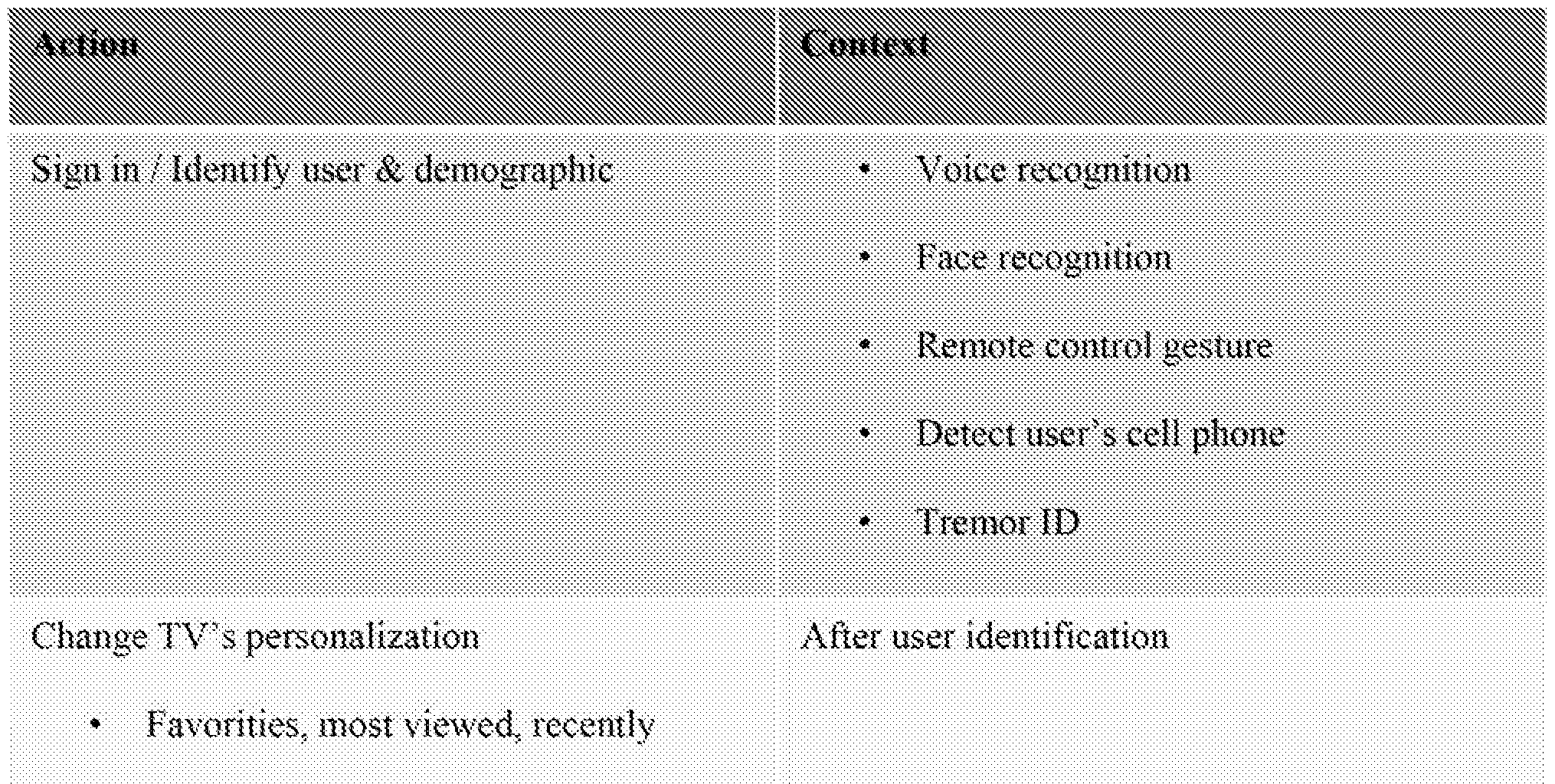
viewed

Table 2
|fl045| it will be appreciaied by those skilled in the art that numerous other types of context/action pairings can be identified and implemented in devices such as smart TVs, Further examples are illustrated below in Table 3.


v lowed
|'0046| Still further examples of context a ware state/action pairings are provided in
Figures 9(a) and 9(b) according to various embodiments, and additional context aspects are shown in Figure 10. Embodiments contemplated herein include implementation of one, any subse or all of the contexts and/or determined context/action pairs described herein.
10047) According to one embodiment, context awareness and subsequent context aware actions can be ordered in a predetermined manner. For example, the smart TV can first determine who the user or users are, i.e., perform an identification of the users, e.g., using any of the technologies discussed above. Then, based on which user or users are identified., the smart
TV can evaluate one or more subcon texts which are identified specifically based on the identity of the user current I v interacting with the smart TV.
{0048! From the foregoing, it will be appreciated that there are potentially a large number of contexts which may be of interest to track, and corresponding context mformadon data elements from which those contexts may be determined. For example, th identity or identities of the person or people in the room with the smart TV can be derived from a number of different pieces of information, e.g., facial recognition from data received, from camera in smart TV, gesture input from the remote control device, presence of users personal devices (cell phone, tablet, etc.) in the room and/or numerous other pieces of information. According to some embodiments, it is contemplated that providing a centralized context repository 1 100 for the smart TV and/or other devices may be useful to store and. provide access to context data, as shown in Figure 1 1(a). Some context information may be generated by the smart TV's own. sensors 1 102, while other context information may be available from other devices in the house 1 104 and/or external sources 1 106, e.g., the internet. Either a push or pull mechanism (or combination of both ) can be used to, periodically or upon data change, u pdate the relevant context information elements in the context repository 1100. The context repositor 1100 can, for example, be implemented in a database or using any type of data structure and can be stored in a memory device either in the smart TV itself or elsewhere in communication with the smart TV.
[0049) Similarly, some applications (Appl -Appm) will be concerned with only a few pieces of context information from which they can determine a rele vant context of a current user of the smart T V and can request that context data from the context repository 1 100 as shown in
Figure 11(b). Context application program interfaces (ΑΡΠ -ΑΡίη) can be provided to interact with the applications running on the smart TV to facilitate context data exchange therebetween. The applications may also generate context data whic can be stored in the context data repository 1100.
|0QS(i| As shown in Figure 8, context can involve the state of a particular user and/or friends and colleagues, the state of a particular device, an activity, a location, local
environmental information, content and/or even external events. In short, context information is very broad indeed. This leads to three iynchpm concepts which are addressed in systems according to various embodiments.
[OOSIf First, a system which implements context-based actions measures, senses or coliects the particular context information that is relevant. If a system wants to know if a person (user) is walking or not, the system needs to measure one or more characteristics from which the state "walking" can be determined or inferred. This measurement could, for example, be performed using an acceieroraeter and/or gyroscope detecting movement and/or gait, e.g., the motion sensor(s) provided in a remote contra! device as described above, or a sensor provided in or on the smart television described earlier.
[0052 | As another example, suppose that weather was a contex t of interest If a sy stem according to these embodiments wants to determine, e.g., if it is raining as context information to store in the context repository 1 100 (or in its own local context database if a centralized context repository is not used), the system can, for example, either directly use a sensor for detecting moisture or, instead, rely on a weather reporting service for the area received over the Internet. For the purposes of these embodiments, it is not necessarily important how context information
is gathered since there exists a vast multitude of ways to do that.
|0053| Second, they system makes the context information accessible to a consuming applicatiori. This means a database or data storage mechanism of some form whether centralized or distributed. Figure 1 1 (a) shows an implementation where the Context Repository 1 100 is centralized. But that Context Repository could also be distributed physically and in the limit come directly from the sources themselves, in that case, the Context Repository is merely a logical construct representing the way information sources (including sensors and sensor assemblies, devices or other sources) make that information available to an application. This could leverage Internet capability including perhaps an addressing scheme like internet of Things proposes,
{00541 Third, such systems according to embodiments have one or more consuming applications that determine which of the nearl infinite amoimt of context, information available is, in fact, relevant to that application. The set of applications and how they might connect to the Context Repository is shown in Figure 1 1 (b). Each application decides which context
information is relevant and retrieves that information from the sources via the appropriate APIs, As discussed previously, the centralized database style of this Context Repository is only one possible embodiment. That Context Repository could in fact merel be a logical construct representing all the information sources available, hi this latter case, each source has at least one Context API through which consuming applications can retrieve the information.
[0055] Each individual application typically only needs a subset of contextual
information in order to perform its function. So, for example, if the application is a thermostat control system for a house, the unit may only need to know which rooms m the house are
occupied, the temperature preferences of the indi viduals in those rooms, the current temperature in those rooms and potentially the temperature outside along with perhaps overall power consumption and cost goals, information on the latest show of American Idol or the Face-book status of a particular user is not relevant to this application and so is ignored, not directly obtained by the application or not requested from the Context Repository 1 100.
| O56i Systems and methods for processing data according to exemplary embodiments of the present invention can be performed by one or more processors executing sequences of instructions contained in a memory device. Such instructions may be read into the memory device from other computer- readable mediums such as secondary data storage deviee(s).
Execution of the sequences of instructions contained in the memory device causes the processor to operate, for example, as described above. In alternative embodiments, hard-wire circuitry may be used in place of or in combination with software instructions to implement the present, invention. Such software may run on a processor which is housed within die device, e.g., a 3D pointing device or other device, which contains the sensors or the software may run on a processor or computer housed within another device, e.g., a system controller, a game console, a personal computer, etc., which is in communication with the device containing the sensors. In such a case, data may be transferred via wireline or wirelesslv between the device containing the sensors and the device containing the processor which runs the software which performs the bias estimation and compensation as described above. According to other exemplary' embodiments, some of the processing described above with respect to context awareness and associated actions may be performed in the device containing the sensors, while the remainder of the processing is performed in a second device after receipt of the partially processed dat from the device
containing the sensors.
|005?J Although the foregoing exemplary embodiments provide for remote devices having sensing packages including one or more rotational sensors and an accelerometer, these exemplary embodiments are not limited to only these types of sensors, instead remote devices as described herein can be applied to devices which include, for example, only aecelerometer(s), optical and inertia! sensors (e.g., a rotational sensor, a gyroscope or an accelerometer), a magnetometer and an inertia! sensor (e.g., a rotational sensor, a gyroscope or an accelerometer), a magnetometer and an optical sensor, or other sensor combinations.
ffl058| Although the foregoing embodiments described context awareness with a focus on smart televisions, it will he appreciated that these techniques are not limited for use in conjunction with televisions but can be used with other smart devices, e.g., mobile phones, tablets, personal computers, refrigerators, cars, etc.
f0059| The above-described exemplary embodiments are intended to be illustrative in all respects, rather than restrictive, of the present invention. Thus the present invention is capable of many variations in detailed implementation that can be derived from the description contained herein by a person skilled in the art. For example, although the foregoing exemplary
embodiments describe, among other things, the use of inertia!, sensors to detect movement of a device, other types of sensors (e.g. , ultrasound, magnetic or optical) can be used instead of, or in addition to, inertial sensors in conjunction with the afore-described signal processing. All such variations and modifications are considered to be within the scope and spirit of the present invention as defined by the following claims. No element, act, or instruction used in the description of the present application should be construed as critical or essential to the invention
unless explicitly described as such. Also, as used herein, the article "a" is intended to include one or more items.
Claims
1. A method for performing a context-based action in a television, the method comprising:
determining, by the television, at least one piece of context information associated with a current usase of the television; and
performing:, by the tele vision, the context-based action based on the at least one piece of context information.
2. The method of claim 1 , wherein the context-based action is switching into a game mode, and wherein the at least one piece of context information is at least one of whether a remote control device is being operated as a game controller and whether an application type being rim on the television is a game.
3. The method of claim 2, wherein switching into a game mode further comprises:
reducing, by the television, image processing to reduce latency.
4. The method of claim. .1 , wherein the context-based action is changing personalization settings on the television, and wherein the at leas one piece of context information is an identit of a current user of the television.
5. The method of claim 4, wherein the television determines the identity of the current user of the television by one of voice recognition, face recognition, gesture or detection of a user's cell phone.
6. The method of claim I , wherein the contex t-based action is turning on or off cursor movement, and wherein the at least one piece of context information is w hether a remote control device is in a user's hand,
7. The method of claim 6, further comprising:
determining whether the remote control device is in the user's hand based on at least one of input from a camera connected to the television and motion information from the remote control device.
8. The method of clai m 15 wherein the con text-based action is entering an exercise mode, and wherei the at least one piece of context information is one of an application type being exercise and a user beginning to exercise.
9. The method of claim L wherein the context-based action i s entering a voice capture mode, and wherein the at least one piece of context information is a remote control device being proximate a user's month.
10. The method of claim 1 , wherein the context-based action is changing personalization settings on the television, and wherein the at least one piece of context information is an identit of a current user of the television,
.
1 1 . A smart television system comprising;
a television display;
at least one television media input configured to receive television programming signals from at least one of a cable TV network and a. satellite TV network;
at least one Internet media input configured to recei ve internet content;
a plurality of sensors including at least two of: a camera, a microphone, an infrared device, and a motion sensor;
a processor configured to output television programming or Internet content to the display and further configured to receive inputs from the plurality of sensors, and to determine a context associated with a current usage of the smart television system based, at least in part, on the received inputs.
wherein the processor is further configured to use the determined context to perform a context-based action.
12. The smart television system of claim 1 1 , wherein the plurality of sensors includes the microphone and the camera, the processor is configured to use the camera to detect that a user has moved a remote control device associated with the smart television into proximity with his or
her mouth as the determined context, and the context-based action is to acti vate a voice capture process using the microphone.
13, The smart television system of claim 1 1 , further comprising a remote control device whose motion can be detected either by one of the plurality of sensors or based on one or more motion sensors within the remote control device, wherein
the processor is configured, to receive information associated with movement of the remote control device, detects motion of the remote control device which indicates that the remote control device is being used as a motion controller for a game, and switches the television system into a low latency image processing mode.
14, The smart television system of claim 1 1 , wherein the plurality of sensors includes a microphone, the processor is configured to perform a voice recognition on captured voice samples of a user of the smart television system using the microphone, the context is the identity of the u ser based on th e v oice recognit ion, and the con text-based ac tion is to c hange one or more personalization settings based o the identity.
15, The smart television system of claim 14, wherein the one or more personalization settings include one or more of: display favorite television program, display favorite Internet Web page, television settings, parental controls, and displayed available applications.
16. The smart television system of claim .1 1 , wherein the plurality of sensors includes a camera, the processor is configured to pertonn a face identification on a captured image of a user of the smart television system using the microphone, the context is the identity of the user based on the fact* recognition, and the context-based action is to change one or more personalization settings based on the identity.
17. The smart television system of claim 16, wherein the one or more personalization settings include one or more of: display favorite television program, dispiay iavorite Internet Web page, television settings, parental controls, and displayed available applications.
18. The smart television system of claim 1 i , wherein the context-based action is entering an exercise mode, and the context, one of an application type being exercise and a user beginning to exercise,
19. The smart television system of claim 1 1 , wherein the context-based action is entering a voice capture mode, and wherein the context is a remote control device being proximate a user's mouth..
20. A method for performing context based actions by a smart, television, comprising:
determining an identity of a user of the smart television;
evaluating one or .more sobcontexts associated with the identified user; and
performing the context-based action based on the evaluating.
21. A context repository system associated with household devices comprising: a memory device configured to store a database of context information associated with the household devices, their environment and their users;
a plurality of interfaces, each associated with one of the household devices, for receiving context information front the household devices and for transmitting context information, to the household devices;
a processor configured to receive the context information from the household devices, to store the received context information in the database, and
further configured to recei ve requests for context information from the household devices, to retrieve the requested context information from the database and to transmit the rec|oested context information back to the requesting household devices.
22. The context repository system of claim 21 , wherein the context information includes at least one of: a current user of one or more of the household devices, a current weather associated with the household, a time of day, a current application being executed on one or more of the household devices.
23. The context repository system of claim 21 , wherein the context information includes each of: a current user of one or more of the household devices, a time of day, and a current, applicatio being executed on one or more of the household, devices.
Priority Applications (1)
| Application Number | Priority Date | Filing Date | Title |
|---|---|---|---|
| US14/438,704 US20150264439A1 (en) | 2012-10-28 | 2013-10-28 | Context awareness for smart televisions |
Applications Claiming Priority (2)
| Application Number | Priority Date | Filing Date | Title |
|---|---|---|---|
| US201261719442P | 2012-10-28 | 2012-10-28 | |
| US61/719,442 | 2012-10-28 |
Publications (2)
| Publication Number | Publication Date |
|---|---|
| WO2014066879A2 true WO2014066879A2 (en) | 2014-05-01 |
| WO2014066879A3 WO2014066879A3 (en) | 2015-07-16 |
Family
ID=50545506
Family Applications (1)
| Application Number | Title | Priority Date | Filing Date |
|---|---|---|---|
| PCT/US2013/067024 Ceased WO2014066879A2 (en) | 2012-10-28 | 2013-10-28 | Context awareness for smart televisions |
Country Status (2)
| Country | Link |
|---|---|
| US (1) | US20150264439A1 (en) |
| WO (1) | WO2014066879A2 (en) |
Cited By (13)
| Publication number | Priority date | Publication date | Assignee | Title |
|---|---|---|---|---|
| US9474529B2 (en) | 2011-11-01 | 2016-10-25 | Zipline Medical, Inc. | Surgical incision and closure apparatus |
| US9561034B2 (en) | 2011-11-01 | 2017-02-07 | Zipline Medical, Inc. | Surgical incision and closure apparatus |
| AU2015306582B2 (en) * | 2014-10-30 | 2017-12-07 | Shenzhen Skyworth-Rgb Electronic Co., Ltd | Context awareness control device, system and method |
| US10010710B2 (en) | 2009-09-17 | 2018-07-03 | Zipline Medical, Inc. | Rapid closing surgical closure device |
| US10123801B2 (en) | 2011-11-01 | 2018-11-13 | Zipline Medical, Inc. | Means to prevent wound dressings from adhering to closure device |
| CN110398897A (en) * | 2018-04-25 | 2019-11-01 | 北京快乐智慧科技有限责任公司 | A kind of Multi-mode switching method and system of intellectual product |
| US10888269B2 (en) | 2014-01-05 | 2021-01-12 | Zipline Medical, Inc. | Instrumented wound closure device |
| US10918332B2 (en) | 2016-10-31 | 2021-02-16 | Zipline Medical, Inc. | Systems and methods for monitoring physical therapy of the knee and other joints |
| US11051988B2 (en) | 2010-06-14 | 2021-07-06 | Zipline Medical, Inc. | Methods and apparatus for inhibiting scar formation |
| WO2021150093A1 (en) * | 2020-01-23 | 2021-07-29 | Samsung Electronics Co., Ltd. | Display apparatus and method of controlling the same |
| US11849415B2 (en) | 2018-07-27 | 2023-12-19 | Mclaren Applied Technologies Limited | Time synchronisation |
| US11898874B2 (en) | 2019-10-18 | 2024-02-13 | Mclaren Applied Technologies Limited | Gyroscope bias estimation |
| US12171432B2 (en) | 2011-11-01 | 2024-12-24 | Zipline Medical, Inc. | Closure apparatuses and methods for ulcers and irregular skin defects |
Families Citing this family (18)
| Publication number | Priority date | Publication date | Assignee | Title |
|---|---|---|---|---|
| TW201439894A (en) * | 2013-04-02 | 2014-10-16 | Hon Hai Prec Ind Co Ltd | Electronic device having message function and method to complete the message thereof |
| KR102164455B1 (en) | 2013-05-08 | 2020-10-13 | 삼성전자주식회사 | Content Providing Method, Content Providing Device and Content Providing System Thereof |
| CN105100950A (en) * | 2014-04-30 | 2015-11-25 | 阿里巴巴集团控股有限公司 | Intelligent television mobile side switching and television side information acquisition method and device and system |
| US20170032783A1 (en) * | 2015-04-01 | 2017-02-02 | Elwha Llc | Hierarchical Networked Command Recognition |
| US20170171616A1 (en) * | 2015-12-11 | 2017-06-15 | Sasken Communication Technologies Ltd | Control of unsuitable video content |
| KR102487902B1 (en) | 2015-12-23 | 2023-01-12 | 삼성전자주식회사 | Method and apparatus for controlling home devices |
| KR102759365B1 (en) * | 2016-05-24 | 2025-01-24 | 삼성전자주식회사 | Electronic device having speech recognition function and operating method of Electronic device |
| CN107734213A (en) * | 2016-08-11 | 2018-02-23 | 漳州立达信光电子科技有限公司 | Smart Home Electronic Devices and Systems |
| US11138262B2 (en) | 2016-09-21 | 2021-10-05 | Melodia, Inc. | Context-aware music recommendation methods and systems |
| US11860677B2 (en) | 2016-09-21 | 2024-01-02 | Melodia, Inc. | Methods and systems for managing media content in a playback queue |
| US10425247B2 (en) | 2017-12-12 | 2019-09-24 | Rovi Guides, Inc. | Systems and methods for modifying playback of a media asset in response to a verbal command unrelated to playback of the media asset |
| KR102502319B1 (en) * | 2017-12-12 | 2023-02-21 | 로비 가이드스, 인크. | Systems and methods for modifying playback of media assets in response to verbal commands unrelated to playback of media assets. |
| US11477516B2 (en) * | 2018-04-13 | 2022-10-18 | Koji Yoden | Services over wireless communication with high flexibility and efficiency |
| US11006183B2 (en) * | 2019-04-24 | 2021-05-11 | ROVl GUIDES, INC. | Method and apparatus for modifying output characteristics of proximate devices |
| US11202128B2 (en) * | 2019-04-24 | 2021-12-14 | Rovi Guides, Inc. | Method and apparatus for modifying output characteristics of proximate devices |
| CN113132774B (en) * | 2019-12-31 | 2024-02-13 | 深圳市茁壮网络股份有限公司 | Control method of intelligent television and related equipment |
| CN111901681B (en) * | 2020-05-04 | 2022-09-30 | 东南大学 | Intelligent television control device and method based on face recognition and gesture recognition |
| US12363369B2 (en) | 2021-07-07 | 2025-07-15 | Sony Group Corporation | Remote control device, related devices, and related methods for identifying a user of a remote control device |
Family Cites Families (14)
| Publication number | Priority date | Publication date | Assignee | Title |
|---|---|---|---|---|
| US8095370B2 (en) * | 2001-02-16 | 2012-01-10 | Agiletv Corporation | Dual compression voice recordation non-repudiation system |
| JP5844044B2 (en) * | 2007-11-21 | 2016-01-13 | クアルコム,インコーポレイテッド | Device access control |
| US8384551B2 (en) * | 2008-05-28 | 2013-02-26 | MedHab, LLC | Sensor device and method for monitoring physical stresses placed on a user |
| WO2010005366A1 (en) * | 2008-07-06 | 2010-01-14 | Tansaki Aktiebolag Ab | Context aware dynamic interface |
| US9014685B2 (en) * | 2009-06-12 | 2015-04-21 | Microsoft Technology Licensing, Llc | Mobile device which automatically determines operating mode |
| US9400548B2 (en) * | 2009-10-19 | 2016-07-26 | Microsoft Technology Licensing, Llc | Gesture personalization and profile roaming |
| US9104238B2 (en) * | 2010-02-12 | 2015-08-11 | Broadcom Corporation | Systems and methods for providing enhanced motion detection |
| DE102010011473A1 (en) * | 2010-03-15 | 2011-09-15 | Institut für Rundfunktechnik GmbH | Method for the remote control of terminals |
| JP5625506B2 (en) * | 2010-06-04 | 2014-11-19 | ソニー株式会社 | Operation terminal device, electronic device, and electronic device system |
| US20120226981A1 (en) * | 2011-03-02 | 2012-09-06 | Microsoft Corporation | Controlling electronic devices in a multimedia system through a natural user interface |
| US20120238215A1 (en) * | 2011-03-15 | 2012-09-20 | Nokia Corporation | Apparatus and Method for a Headset Device |
| CA2868276A1 (en) * | 2011-03-23 | 2013-09-27 | Mgestyk Technologies Inc. | Apparatus and system for interfacing with computers and other electronic devices through gestures by using depth sensing and methods of use |
| WO2012169679A1 (en) * | 2011-06-10 | 2012-12-13 | 엘지전자 주식회사 | Display apparatus, method for controlling display apparatus, and voice recognition system for display apparatus |
| US8863042B2 (en) * | 2012-01-24 | 2014-10-14 | Charles J. Kulas | Handheld device with touch controls that reconfigure in response to the way a user operates the device |
-
2013
- 2013-10-28 WO PCT/US2013/067024 patent/WO2014066879A2/en not_active Ceased
- 2013-10-28 US US14/438,704 patent/US20150264439A1/en not_active Abandoned
Cited By (25)
| Publication number | Priority date | Publication date | Assignee | Title |
|---|---|---|---|---|
| US10010710B2 (en) | 2009-09-17 | 2018-07-03 | Zipline Medical, Inc. | Rapid closing surgical closure device |
| US10159825B2 (en) | 2009-09-17 | 2018-12-25 | Zipline Medical, Inc. | Rapid closing surgical closure device |
| US11051988B2 (en) | 2010-06-14 | 2021-07-06 | Zipline Medical, Inc. | Methods and apparatus for inhibiting scar formation |
| US10123800B2 (en) | 2011-11-01 | 2018-11-13 | Zipline Medical, Inc. | Surgical incision and closure apparatus with integrated force distribution |
| US9554799B2 (en) | 2011-11-01 | 2017-01-31 | Zipline Medical, Inc. | Surgical incision and closure apparatus |
| US9642622B2 (en) | 2011-11-01 | 2017-05-09 | Zipline Medical, Inc. | Surgical incision and closure apparatus |
| US11439395B2 (en) | 2011-11-01 | 2022-09-13 | Zipline Medical, Inc. | Surgical incision and closure apparatus |
| US9561034B2 (en) | 2011-11-01 | 2017-02-07 | Zipline Medical, Inc. | Surgical incision and closure apparatus |
| US9474529B2 (en) | 2011-11-01 | 2016-10-25 | Zipline Medical, Inc. | Surgical incision and closure apparatus |
| US10123801B2 (en) | 2011-11-01 | 2018-11-13 | Zipline Medical, Inc. | Means to prevent wound dressings from adhering to closure device |
| US9642621B2 (en) | 2011-11-01 | 2017-05-09 | ZipLine Medical, Inc | Surgical incision and closure apparatus |
| US10456136B2 (en) | 2011-11-01 | 2019-10-29 | Zipline Medical, Inc. | Surgical incision and closure apparatus |
| US12171432B2 (en) | 2011-11-01 | 2024-12-24 | Zipline Medical, Inc. | Closure apparatuses and methods for ulcers and irregular skin defects |
| US9554800B2 (en) | 2011-11-01 | 2017-01-31 | Zipline Medical, Inc. | Surgical incision and closure apparatus |
| US11844625B2 (en) | 2014-01-05 | 2023-12-19 | Zipline Medical, Inc. | Instrumented wound closure device |
| US10888269B2 (en) | 2014-01-05 | 2021-01-12 | Zipline Medical, Inc. | Instrumented wound closure device |
| AU2015306582B2 (en) * | 2014-10-30 | 2017-12-07 | Shenzhen Skyworth-Rgb Electronic Co., Ltd | Context awareness control device, system and method |
| US11033270B2 (en) | 2015-08-07 | 2021-06-15 | Zipline Medical, Inc. | Means to prevent wound dressings from adhering to closure device |
| US11337649B2 (en) | 2016-10-31 | 2022-05-24 | Zipline Medical, Inc. | Systems and methods for monitoring physical therapy of the knee and other joints |
| US10918332B2 (en) | 2016-10-31 | 2021-02-16 | Zipline Medical, Inc. | Systems and methods for monitoring physical therapy of the knee and other joints |
| US11992334B2 (en) | 2016-10-31 | 2024-05-28 | Zipline Medical, Inc. | Systems and methods for monitoring physical therapy of the knee and other joints |
| CN110398897A (en) * | 2018-04-25 | 2019-11-01 | 北京快乐智慧科技有限责任公司 | A kind of Multi-mode switching method and system of intellectual product |
| US11849415B2 (en) | 2018-07-27 | 2023-12-19 | Mclaren Applied Technologies Limited | Time synchronisation |
| US11898874B2 (en) | 2019-10-18 | 2024-02-13 | Mclaren Applied Technologies Limited | Gyroscope bias estimation |
| WO2021150093A1 (en) * | 2020-01-23 | 2021-07-29 | Samsung Electronics Co., Ltd. | Display apparatus and method of controlling the same |
Also Published As
| Publication number | Publication date |
|---|---|
| WO2014066879A3 (en) | 2015-07-16 |
| US20150264439A1 (en) | 2015-09-17 |
Similar Documents
| Publication | Publication Date | Title |
|---|---|---|
| WO2014066879A2 (en) | Context awareness for smart televisions | |
| KR102700793B1 (en) | Display device | |
| EP3342170B1 (en) | Electronic device and method of scanning channels in electronic device | |
| US9411428B2 (en) | 3D pointing devices with keyboards | |
| US9414125B2 (en) | Remote control device | |
| CN102970606B (en) | The TV programme suggesting method and device of identity-based identification | |
| US9538245B2 (en) | Media system and method of providing recommended search term corresponding to an image | |
| US10545577B2 (en) | 3D pointing device with up-down-left-right mode switching and integrated swipe detector | |
| US20100330979A1 (en) | Portable Phone Remote | |
| CN112087666B (en) | A method for adjusting the progress of multimedia playback | |
| KR101821781B1 (en) | Determining forward pointing direction of a handheld device | |
| US11099031B2 (en) | Methods and apparatus for determining the zero rate output of a sensor using a learning algorithm | |
| US20170019701A1 (en) | Apparatus for displaying an image and method of operating the same | |
| US20230036884A1 (en) | Display device | |
| EP3333677B1 (en) | Method for generating either a scroll command or an up-down-left-right command and three dimensional pointing device | |
| CN114339346B (en) | Display device and image recognition result display method | |
| US20200204870A1 (en) | Client device, companion screen device, and operation method therefor | |
| US20120242601A1 (en) | Assembly Of A Display Apparatus And A Remote Control And A Method Of Operating The Assembly | |
| KR102267194B1 (en) | Terminal and operating method thereof | |
| US10083212B2 (en) | Method and apparatus of representing content information using sectional notification method | |
| KR20250068660A (en) | Display device and method of operation thereof | |
| WO2017120300A1 (en) | Content delivery systems and methods |
Legal Events
| Date | Code | Title | Description |
|---|---|---|---|
| 121 | Ep: the epo has been informed by wipo that ep was designated in this application |
Ref document number: 13848308 Country of ref document: EP Kind code of ref document: A2 |
|
| WWE | Wipo information: entry into national phase |
Ref document number: 14438704 Country of ref document: US |
|
| NENP | Non-entry into the national phase |
Ref country code: DE |
|
| 122 | Ep: pct application non-entry in european phase |
Ref document number: 13848308 Country of ref document: EP Kind code of ref document: A2 |