WO2013028726A1 - High-volume fast separation of multi-phase components in fluid suspensions - Google Patents
High-volume fast separation of multi-phase components in fluid suspensions Download PDFInfo
- Publication number
- WO2013028726A1 WO2013028726A1 PCT/US2012/051804 US2012051804W WO2013028726A1 WO 2013028726 A1 WO2013028726 A1 WO 2013028726A1 US 2012051804 W US2012051804 W US 2012051804W WO 2013028726 A1 WO2013028726 A1 WO 2013028726A1
- Authority
- WO
- WIPO (PCT)
- Prior art keywords
- flow chamber
- outlet
- particles
- acoustic
- particulate
- Prior art date
- Legal status (The legal status is an assumption and is not a legal conclusion. Google has not performed a legal analysis and makes no representation as to the accuracy of the status listed.)
- Ceased
Links
- LYQFHSZMISRFCC-UHFFFAOYSA-N CCC(CC1)C1C(CC1)C1C(CC1)C11C(CC)CCC1 Chemical compound CCC(CC1)C1C(CC1)C1C(CC1)C11C(CC)CCC1 LYQFHSZMISRFCC-UHFFFAOYSA-N 0.000 description 1
Classifications
-
- B—PERFORMING OPERATIONS; TRANSPORTING
- B03—SEPARATION OF SOLID MATERIALS USING LIQUIDS OR USING PNEUMATIC TABLES OR JIGS; MAGNETIC OR ELECTROSTATIC SEPARATION OF SOLID MATERIALS FROM SOLID MATERIALS OR FLUIDS; SEPARATION BY HIGH-VOLTAGE ELECTRIC FIELDS
- B03B—SEPARATING SOLID MATERIALS USING LIQUIDS OR USING PNEUMATIC TABLES OR JIGS
- B03B5/00—Washing granular, powdered or lumpy materials; Wet separating
-
- B—PERFORMING OPERATIONS; TRANSPORTING
- B01—PHYSICAL OR CHEMICAL PROCESSES OR APPARATUS IN GENERAL
- B01D—SEPARATION
- B01D21/00—Separation of suspended solid particles from liquids by sedimentation
- B01D21/28—Mechanical auxiliary equipment for acceleration of sedimentation, e.g. by vibrators or the like
- B01D21/283—Settling tanks provided with vibrators
-
- C—CHEMISTRY; METALLURGY
- C02—TREATMENT OF WATER, WASTE WATER, SEWAGE, OR SLUDGE
- C02F—TREATMENT OF WATER, WASTE WATER, SEWAGE, OR SLUDGE
- C02F1/00—Treatment of water, waste water, or sewage
- C02F1/34—Treatment of water, waste water, or sewage with mechanical oscillations
- C02F1/36—Treatment of water, waste water, or sewage with mechanical oscillations ultrasonic vibrations
-
- C—CHEMISTRY; METALLURGY
- C12—BIOCHEMISTRY; BEER; SPIRITS; WINE; VINEGAR; MICROBIOLOGY; ENZYMOLOGY; MUTATION OR GENETIC ENGINEERING
- C12M—APPARATUS FOR ENZYMOLOGY OR MICROBIOLOGY; APPARATUS FOR CULTURING MICROORGANISMS FOR PRODUCING BIOMASS, FOR GROWING CELLS OR FOR OBTAINING FERMENTATION OR METABOLIC PRODUCTS, i.e. BIOREACTORS OR FERMENTERS
- C12M47/00—Means for after-treatment of the produced biomass or of the fermentation or metabolic products, e.g. storage of biomass
- C12M47/02—Separating microorganisms from the culture medium; Concentration of biomass
-
- B—PERFORMING OPERATIONS; TRANSPORTING
- B01—PHYSICAL OR CHEMICAL PROCESSES OR APPARATUS IN GENERAL
- B01D—SEPARATION
- B01D21/00—Separation of suspended solid particles from liquids by sedimentation
- B01D21/28—Mechanical auxiliary equipment for acceleration of sedimentation, e.g. by vibrators or the like
Definitions
- the subject matter described herein relates to techniques for separating multiphase components within fluid suspensions such as water.
- a flow chamber through which is flowed a mixture of a fluid and a particulate.
- the flow chamber comprises at least one multi-phase water inlet through which multi-phase water enters the flow chamber, a water outlet through which water exits the flow chamber, a solids outlet through which particles having a density at or above a pre-defined threshold exit the flow chamber, and a low density outlet through which particles having a density below the pre-defined threshold exit the flow chamber.
- one or more ultrasonic transducers and one or more reflectors corresponding to each transducer are also provided.
- Each transducer forms a standing acoustic wave at a different ultrasonic frequency and each ultrasonic frequency is optimized for a specific range of particle sizes to, along with a geometry of the flow chamber, selectively separate particles from the multi-phase water and water so that such particles exit the flow chamber via one of the solids outlet and the low density outlet.
- the one or more ultrasonic transducers operate at a frequency in a range of 1 MHz to 10 MHz, and in some implementations, the one or more ultrasonic transducers operate at a frequency in a range of 100 kHz to 20 MHz.
- the one or more ultrasonic transducers can be embedded in a wall of the flow chamber.
- the one or more ultrasonic transducers can be arranged in a flat series. In arrangements with multiple transducers, the transducers can be arranged in a parallel array within an inner portion of the flow chamber.
- the flow chamber can be vertically oriented (relatively to gravity) with the low density outlet being on an upper portion and the solids outlet being on a lower portion.
- the flow chamber can be horizontally oriented with the low density outlet being on the upper portion and the solids outlet being on the lower portion.
- the flow chamber can alternatively be diagonally oriented with the low density outlet being on the upper incline and the solids outlet being on the lower incline. With a diagonal arrangement, the multi-phase water inlet can be at an obtuse angle from an outer wall of the flow chamber relative to the solids outlet.
- the multi-phase water inlet can be disposed between the low density outlet and the two or more ultrasonic transducers.
- the multi -phase water inlet can be at an acute angle from an outer wall of the flow chamber relative to the solids outlet.
- the water outlet can be disposed between the two or more ultrasonic transducers and the solids outlet.
- he particles can be selected from a group comprising: microalgae, yeast, fungi, bacteria, spores, gases or oils, metal oxides, metal particles, clays, dirt, plastics, and any particulate with a non-zero contrast factor.
- each transducer can be optimized for a specific range of particles (which can be mutually exclusive) selected from a group consisting of microalgae, yeast, fungi, bacteria, spores, gases or oils, metal oxides, metal particles, clays, dirt, plastics, and any particulate with a non-zero contrast factor.
- the one or more ultrasonic transducers can each generate acoustic standing waves perpendicular, to the direction of the mean flow in the flow channel.
- the one or more acoustic standing waves have a or a vertical horizontal orientation.
- the one or more acoustic standing waves can exert acoustic radiation force on the particulate for which the ultrasonic frequency is optimized for, such that the particulate is trapped in its corresponding acoustic standing wave against a fluid drag force such that the particulate is concentrated in the acoustic field over time.
- the solids outlet can be tapered.
- the flow chamber can be oriented such that the multi-phase water is gravity fed from the multi-phase water inlet towards the solids outlet.
- a method of separating particulate from a fluid comprises: flowing the fluid past one or more positions within a flow chamber and forming acoustic standing waves at the one or more positions.
- each standing acoustic wave is maintained at a different ultrasonic frequency such that each ultrasonic frequency is optimized for a specific range of particle sizes and wherein particulate of the optimized size is trapped in its corresponding acoustic standing wave against the flow of the fluid, thereby concentrating the particulate in its corresponding acoustic standing wave.
- the flow chamber can comprise at least one multi-phase water inlet through which multi-phase water enters the flow chamber, a water outlet through which water exits the flow chamber, a solids outlet through which particles having a density at or above a predefined threshold exit the flow chamber, and a low density outlet through which particles having a density below the pre-defined threshold exit the flow chamber.
- an apparatus in yet another aspect, includes a flow chamber through which is flowed a mixture of a fluid and a particulate.
- the flow chamber comprises at least one multi-phase water inlet through which multi-phase water enters the flow chamber, a water outlet through which water exits the flow chamber, a solids outlet through which agglomerated microorganisms and dirt exit the flow chamber, and a low density outlet through which agglomerated oil droplets exit the flow chamber.
- Also included can be one or more ultrasonic transducers, and one or more reflectors corresponding to each transducer.
- each transducer forms a standing acoustic wave at a different ultrasonic frequency and each ultrasonic frequency is optimized for a specific range of particle sizes to, along with a geometry of the flow chamber, selectively separate particles from the multi-phase water and water so that such particles exit the flow chamber via one of the solids outlet and the low density outlet.
- the current subject matter provides many advantages. For example, it allows for the efficient trapping, concentrating, and separation of various types of suspended particles, microorganisms and droplets from a host medium such as water.
- FIG. 1 is a diagram illustrating acoustic contrast, particle radius, and acoustic radiation force on particles for a given frequency of excitation and acoustic pressure level;
- FIG. 2 is a schematic diagram of a first implementation having a parallel and/or serial array of tube-shaped transducers for agglomeration of and coalescence of suspended particles utilizing acoustic standing waves;
- FIG. 3 is a schematic diagram of a second implementation in which there are flat transducers for agglomeration of and coalescence of suspended particles utilizing acoustic standing waves;
- FIG. 4A is a photograph of collected iron oxide using a system such as that illustrated in FIGs. 2-3;
- FIG. 4B is a photograph of collected microalgae using a system such as that illustrated in FIGs. 2-3;
- FIG. 4C is a photograph of collected bacterial spores using a system such as that illustrated in FIGs. 2-3;
- FIG. 4D is a photograph of separated oil using a system such as that illustrated in FIGs. 2-3;
- FIG. 5 is a diagram illustrating oil concentration at a transducer frequency of 250 kHz and exposure time of 0.1 s;
- FIG. 6 is a diagram illustrating oil concentration at a transducer frequency of 1 MHz and exposure time of 0.1 s;
- FIG. 7 is a diagram illustrating oil concentration at a transducer frequency of 10 MHz and exposure time of 0. Is;
- FIG. 8 is a diagram illustrating magnetic beads concentration at a transducer frequency of 250 kHz and exposure time of 0.1 s;
- FIG. 9 is a diagram illustrating magnetic beads separation at a transducer frequency of 1 MHz and exposure time of 0.1 s;
- FIG. 10 is a diagram illustrating magnetic beads separation at a transducer frequency of 10 MHz and exposure time of 0.1s.
- FIG. 1 1 is a photograph illustrating an acoustic standing wave in a tube shaped transducer.
- the current subject matter utilizes acoustophoresis, a low-power, no- pressure-drop, no-clog, solid-state approach to particle removal from fluid dispersions: i.e., it is used to achieve separations that are more typically performed with porous filters and centrifuges, but it has none of the disadvantages of these systems.
- the diagram 100 of FIG. 1 shows the acoustic radiation forces acting on a suspended particle for an applied acoustic frequency of 1 MHz (typical for an ultrasonic transducer) and an acoustic pressure of 0.5 MPa maximum at the antinodes (readily achieved in water).
- the acoustic radiation force acts on the secondary-phase particles (or fluid droplets), pushing them to the nodes (or antinodes) of the acoustic standing wave.
- the magnitude of the force depends on the particle density and compressibility relative to the fluid medium, and increases with the particle volume.
- the diagram 100 of FIG. 1 illustrates the acoustic force that operates on four different secondary phases in water as a function of the particle (or droplet) radius.
- the four secondary phases are hexanes (a mixture of hydrocarbons, a model for oils), red blood cells (a model for biological cells), bacterial spores (a model for "large” protein clusters and polystyrene beads such as are used for flow cytometry), and paramagnetic polystyrene beads (used for various biological capture and separation protocols). Parameters used in the calculation of the acoustic force are given below in Table 1.
- concentration ratio has been as high as 1000 in a single-pass, small-scale prototype acoustocoUector.
- the techniques described in this paper will scale up to higher flow rates or larger flow channel, which has been proven in a 6" x 6" system and processing to 12" in dimension.
- the current subject matter allows for the simultaneous agglomeration of suspended solids such as microorganisms and dirt (metal oxides) and oil droplets.
- suspended solids such as microorganisms and dirt (metal oxides) and oil droplets.
- the ability to translate and concentrate these secondary phases is known as acoustophoresis.
- Described herein is an improved flow chamber with two different ultrasonic transducer arrangements.
- Diagrams 200, 300 respectively of FIGs. 2-3 show two different transducer arrangements for two variations of an overall-view of the current systems which utilize a series of solid cylindrical and hollow cylindrical transducers with the flowing water for particle agglomeration.
- a small experimental system put together by the inventors that demonstrate the concept is described below.
- a flow chamber 210 is illustrated having a multi-phase water inlet 220, a low density outlet 230, a water outlet 240, and a solids outlet 250. It will be appreciated that there may be two or more of each inlet and outlet depending on the desired configuration and volumes being processed.
- Multi-phase water i.e., water having suspended particulate, etc.
- An acoustic standing wave is generated in the middle of the flow chamber 210, either by a set of tube-shaped transducers 260 arranged in a parallel spacing within a center portion of the flow chamber or by an array of flat transducers 310, causes the particles (oil droplets) to agglomerate at the nodes (antinodes) in the acoustic wave.
- the agglomeration for high density particles will eventually result in their growing so as to overcome the acoustic pinning force and gravity settling causes them to fall into solids outlet 250.
- the agglomeration at the antinodes will result in droplet coalescence and they will be able to overcome the acoustic pinning force and buoyancy force causes the larger droplets to drift to the low density outlet 230.
- FIGS. 4A-D show several examples in the photographs in FIGS. 4A-D.
- the first photo 410 shows the acoustophoretic collection of iron oxide particles
- the second photograph 420 shows the collection of algae
- the third photograph 430 shows the collection of bacterial spores
- the fourth photograph 440 shows the collection of oil droplets, all in a flowing water stream.
- a flat, circular transducer can, for example, be used in an acoustocollector to generate the collected matter in FIGs. 4A-D.
- the radial component of the pressure field of such a transducer is described by a Bessel function t whereas the axial component is described by a cosine function such as in the case of a one dimensional standing wave.
- the radial component acts to hold the captured algae in the column against the fluid flow drag force.
- the trapped algae are then further concentrated by inter-particles forces.
- the particles are then further separated from the flow by gravitational settling or by being driven to a collector pocket through a slow frequency sweeping method similar to that given in (i) B. Lipkens, M. Costolo, and E. Rietman , "The effect of frequency sweeping and fluid flow on particle trajectories in ultrasonic standing waves", IEEE Sensors Journal, Vol. 8, No. 6, pp. 667-677, 2008; (ii) Lipkens, J. Dionne, M. Costolo, and E.
- Acoustophoresis is the separation of a second phase (or phases) from a host fluid using sound pressure to create the driving force.
- An ultrasonic transducer operating at a fixed frequency f (Hz) is used to set up an acoustic standing wave in a fluid-filled cavity.
- R p is the particle radius
- p/ is the density of the fluid medium
- cy is the speed of sound in the fluid
- X is the acoustic contrast factor, defined by where ⁇ is the ratio of the particle density to fluid density and ⁇ is the ratio of the speed of sound in the particle to the sound speed in the fluid.
- the acoustic radiation force acts in the direction of the acoustic field.
- the acoustic radiation force is proportional to the product of acoustic pressure and acoustic pressure gradient.
- the acoustic radiation force is thus a function of two mechanical properties, namely density and compressibility.
- f and f 2 are the monopole and dipole contributions defined by
- V 0 is the volume of the particle.
- the diagram 100 of FIG. 1 shows the force required to separate small particles of various material properties. Each material has its own X parameter given in Equation [3].
- material properties e.g. speed of sound, density
- the graph for bacteria spore is also valid for other materials of similar bulk modulus. Meaning smaller bacteria spore, very large protein clusters, and polystyrene microspheres would all be in this category.
- the blood cell curve is for any cells of similar bulk modulus.
- the hexane curve would be valid for any tiny drops of oil-like material with the radius indicated on the curve. These curves are for, as an example, 1 MHz applied acoustic frequency and an acoustic pressure of 0.5 MPa. These are easily achieved control variables. Higher frequency and higher pressure will afford better separation of smaller particles - down to 10s of nm.
- n is the number density of the suspended particulate
- f is the frequency
- c is the speed of sound
- E ac is the energy density of the acoustic wave
- R is the particle radius
- X is the contrast factor
- t is time
- m is the dynamic viscosity of the fluid
- x is position in the standing wave.
- the equation describes the kinetics of the particles in the standing wave as a result of the action of the drag force and acoustic radiation force. This equation is derived in the paper by Feke et al.
- FIGs. 5-10 plot the relative concentration, capture efficiency for different size particles of different densities and different frequencies.
- the x-axis is direction the particles travel from 0 to 2/2.
- the y-axis is the concentration relative to the initial of 1.
- Diagram 500 of FIG. 5 shows the separation at 250 kHz for oil and an acoustic pressure amplitude of 250 kHz. Three particles sizes are shown; in black a 1 mm radius particle, in green a 10 mm radius particle, and in red a 100 mm radius particle. We see that the large droplets are heavily concentrated at the pressure anti-nodal planes of the standing wave, whereas the intermediate and small particle have not undergone any appreciable concentration. This situation can be used to selectively concentrate and separate large particles, and exhibits size-exclusion behavior.
- Diagram 600 of FIG. 6 shows separation at 1 MHz for oil. Here one can see a concentration efficiency of much greater than 20: 1 for the intermediate and large droplets, and only minor changes for the small droplets.
- diagram 700 of Fig. 7 shows separation at 10 MHz, where the intermediate and small particles are heavily concentrated, but not the large ones. This is caused by the fact that the large particles are of the same order as the wavelength, and the acoustic radiation force is no longer effective. This is significant, because it shows a size-exclusion behavior that can be further exploited for preparation of very fine emulsions of biologically significant agents.
- FIGs. 8-10 show analogous conditions for iron oxide (Fe0 2 , a metal oxide simulant).
- Diagram 800 of FIG. 8 shows concentration at 250 kHz and 250 kPa for large, intermediate, and small particles of 100, 10, and 1 micron. We observe that particles with positive contrast move to the pressure nodes. It also shows that the large particles are concentrated significantly at the pressure nodes, and intermediate and smaller particles are not concentrated. Therefore, size-exclusion can work here as well.
- Diagram 900 of Fig. 9 shows the concentration at 1 MHz and 1 MPa, and shows that large and intermediate particles are concentrated but not small ones.
- diagram 1000 of Fig. 10 shows concentration at 10 MHz, where intermediate and small particles are concentrated.
- the large particles are of similar magnitude as the wavelength and do not experience significant concentration. Analogous behavior is observed for micro- algae, bacteria, and blood cells. Like the oil case above, this is also significant because it demonstrates that the current subject matter can be applied for biotechnology applications for separating species of various sizes, essentially a high-flow, large-volume, size- exclusion separation technology. It also shows promise for lipid and platelet separation of blood.
- FIG. 1 The first implementation is shown in Figure 2 with further details in the diagram 1 100 of FIG. 1 1.
- a multiphase-water mixture is pumped into the flow chamber 210 via the multi-phase water inlet 220 device from the where it encounters a parallel array of tube-shaped transducers 260 each operating at 1 - 10 MHz frequency.
- the agglomeration occurs and due to gravity the large clumps fall into the solids outlet 250 (e.g., a collection port, etc.).
- Any coalesced oil, or oil-like substances will overcome buoyancy and self-transport to the respective low density outlet 230 on the top of the flow chamber 210.
- 1 1 shows pressure nodes in the tube-shaped transducer array 260.
- a multiphase- water mixture is pumped into the flow chamber 210 via the multi-phase water inlet 220 where it encounters a serial array of flat 1cm transducers 310 operating at a frequency range between 1 and 10 MHz.
- the solids outlet 250 e.g., a collection port, etc.
- Any coalesced oil, or oil-like substances, will overcome buoyancy and self- transport to the low density outlet 230 on the top of the flow chamber 210.
- the term outlet can comprise a piped exit from the flow chamber 210 or it can comprise a collection port requiring periodic removal of separated particulate.
Landscapes
- Engineering & Computer Science (AREA)
- Life Sciences & Earth Sciences (AREA)
- Chemical & Material Sciences (AREA)
- Organic Chemistry (AREA)
- Health & Medical Sciences (AREA)
- Mechanical Engineering (AREA)
- Zoology (AREA)
- Wood Science & Technology (AREA)
- Bioinformatics & Cheminformatics (AREA)
- Biotechnology (AREA)
- Biomedical Technology (AREA)
- Biochemistry (AREA)
- Water Supply & Treatment (AREA)
- Microbiology (AREA)
- Sustainable Development (AREA)
- Environmental & Geological Engineering (AREA)
- Hydrology & Water Resources (AREA)
- Chemical Kinetics & Catalysis (AREA)
- General Engineering & Computer Science (AREA)
- General Health & Medical Sciences (AREA)
- Genetics & Genomics (AREA)
- Physical Water Treatments (AREA)
- Physical Or Chemical Processes And Apparatus (AREA)
- Apparatus Associated With Microorganisms And Enzymes (AREA)
Abstract
A flow chamber is provided through which is flowed a mixture of a fluid and a particulate. The flow chamber comprises at least one multi-phase water inlet through which multi-phase water enters the flow chamber, a water outlet through which water exits the flow chamber, a solids outlet through which particles having a density at or above a pre-defined threshold exit the flow chamber, and a low density outlet through which particles having a density below the pre-defined threshold exit the flow chamber. Also provided are one or more ultrasonic transducers and one or more reflectors corresponding to each transducer to acoustically filter the fluid and cause particles / fluid to be selectively diverted to one of the outlets. Related apparatus, systems, techniques and articles are also described.
Description
High- Volume Fast Separation of Multi-phase Components in Fluid
Suspensions
RELATED APPLICATION
[0001] This application claims priority to U.S. Pat. App. Ser. No. 61/402,079 filed on August 23, 2010, the contents of which are hereby fully incorporated by reference.
TECHNICAL FIELD
[0002] The subject matter described herein relates to techniques for separating multiphase components within fluid suspensions such as water.
BACKGROUND
[0003] Numerous processes require the removal of solids, microorganisms, and oils that are suspended in a water matrix. For example, water can include suspended oils and dirt which must be removed for human use either for irrigation, or industrial processes, or recycling. However, accurate removal or separation of particles from water can be costly and/or time consuming especially when high volumes of water are being treated.
SUMMARY
[0004] In one aspect, a flow chamber is provided through which is flowed a mixture of a fluid and a particulate. The flow chamber comprises at least one multi-phase water inlet through which multi-phase water enters the flow chamber, a water outlet through which water exits the flow chamber, a solids outlet through which particles
having a density at or above a pre-defined threshold exit the flow chamber, and a low density outlet through which particles having a density below the pre-defined threshold exit the flow chamber. Also provided are one or more ultrasonic transducers and one or more reflectors corresponding to each transducer. Each transducer forms a standing acoustic wave at a different ultrasonic frequency and each ultrasonic frequency is optimized for a specific range of particle sizes to, along with a geometry of the flow chamber, selectively separate particles from the multi-phase water and water so that such particles exit the flow chamber via one of the solids outlet and the low density outlet.
[0005] The one or more ultrasonic transducers operate at a frequency in a range of 1 MHz to 10 MHz, and in some implementations, the one or more ultrasonic transducers operate at a frequency in a range of 100 kHz to 20 MHz. The one or more ultrasonic transducers can be embedded in a wall of the flow chamber. The one or more ultrasonic transducers can be arranged in a flat series. In arrangements with multiple transducers, the transducers can be arranged in a parallel array within an inner portion of the flow chamber.
[0006] The flow chamber can be vertically oriented (relatively to gravity) with the low density outlet being on an upper portion and the solids outlet being on a lower portion. In other implementations, the flow chamber can be horizontally oriented with the low density outlet being on the upper portion and the solids outlet being on the lower portion. The flow chamber can alternatively be diagonally oriented with the low density outlet being on the upper incline and the solids outlet being on the lower incline. With a diagonal arrangement, the multi-phase water inlet can be at an obtuse angle from an outer wall of the flow chamber relative to the solids outlet.
[0007] The multi-phase water inlet can be disposed between the low density outlet and the two or more ultrasonic transducers. The multi -phase water inlet can be at an acute angle from an outer wall of the flow chamber relative to the solids outlet. The water outlet can be disposed between the two or more ultrasonic transducers and the solids outlet.
[0008] he particles can be selected from a group comprising: microalgae, yeast, fungi, bacteria, spores, gases or oils, metal oxides, metal particles, clays, dirt, plastics, and any particulate with a non-zero contrast factor. In arrangement with multiple transducers, each transducer can be optimized for a specific range of particles (which can be mutually exclusive) selected from a group consisting of microalgae, yeast, fungi, bacteria, spores, gases or oils, metal oxides, metal particles, clays, dirt, plastics, and any particulate with a non-zero contrast factor.
[0009] The one or more ultrasonic transducers can each generate acoustic standing waves perpendicular, to the direction of the mean flow in the flow channel. In other arrangements, the one or more acoustic standing waves have a or a vertical horizontal orientation. The one or more acoustic standing waves can exert acoustic radiation force on the particulate for which the ultrasonic frequency is optimized for, such that the particulate is trapped in its corresponding acoustic standing wave against a fluid drag force such that the particulate is concentrated in the acoustic field over time.
[0010] In addition, the solids outlet can be tapered. The flow chamber can be oriented such that the multi-phase water is gravity fed from the multi-phase water inlet towards the solids outlet.
[0011] In another aspect, a method of separating particulate from a fluid is provided that comprises: flowing the fluid past one or more positions within a flow chamber and forming acoustic standing waves at the one or more positions. In such an arrangement, each standing acoustic wave is maintained at a different ultrasonic frequency such that each ultrasonic frequency is optimized for a specific range of particle sizes and wherein particulate of the optimized size is trapped in its corresponding acoustic standing wave against the flow of the fluid, thereby concentrating the particulate in its corresponding acoustic standing wave. With such an arrangement, the flow chamber can comprise at least one multi-phase water inlet through which multi-phase water enters the flow chamber, a water outlet through which water exits the flow chamber, a solids outlet through which particles having a density at or above a predefined threshold exit the flow chamber, and a low density outlet through which particles having a density below the pre-defined threshold exit the flow chamber.
[0012] In yet another aspect, an apparatus includes a flow chamber through which is flowed a mixture of a fluid and a particulate. The flow chamber comprises at least one multi-phase water inlet through which multi-phase water enters the flow chamber, a water outlet through which water exits the flow chamber, a solids outlet through which agglomerated microorganisms and dirt exit the flow chamber, and a low density outlet through which agglomerated oil droplets exit the flow chamber. Also included can be one or more ultrasonic transducers, and one or more reflectors corresponding to each transducer. With this arrangement, each transducer forms a standing acoustic wave at a different ultrasonic frequency and each ultrasonic frequency is optimized for a specific range of particle sizes to, along with a geometry of the flow
chamber, selectively separate particles from the multi-phase water and water so that such particles exit the flow chamber via one of the solids outlet and the low density outlet.
[0013] The current subject matter provides many advantages. For example, it allows for the efficient trapping, concentrating, and separation of various types of suspended particles, microorganisms and droplets from a host medium such as water.
[0014] The details of one or more variations of the subject matter described herein are set forth in the accompanying drawings and the description below. Other features and advantages of the subject matter described herein will be apparent from the description and drawings, and from the claims.
DESCRIPTION OF DRAWINGS
[0015] FIG. 1 is a diagram illustrating acoustic contrast, particle radius, and acoustic radiation force on particles for a given frequency of excitation and acoustic pressure level;
[0016] FIG. 2 is a schematic diagram of a first implementation having a parallel and/or serial array of tube-shaped transducers for agglomeration of and coalescence of suspended particles utilizing acoustic standing waves;
[0017] FIG. 3 is a schematic diagram of a second implementation in which there are flat transducers for agglomeration of and coalescence of suspended particles utilizing acoustic standing waves;
[0018] FIG. 4A is a photograph of collected iron oxide using a system such as that illustrated in FIGs. 2-3;
[0019] FIG. 4B is a photograph of collected microalgae using a system such as that illustrated in FIGs. 2-3;
[0020] FIG. 4C is a photograph of collected bacterial spores using a system such as that illustrated in FIGs. 2-3;
[0021] FIG. 4D is a photograph of separated oil using a system such as that illustrated in FIGs. 2-3;
[0022] FIG. 5 is a diagram illustrating oil concentration at a transducer frequency of 250 kHz and exposure time of 0.1 s;
[0023] FIG. 6 is a diagram illustrating oil concentration at a transducer frequency of 1 MHz and exposure time of 0.1 s;
[0024] FIG. 7 is a diagram illustrating oil concentration at a transducer frequency of 10 MHz and exposure time of 0. Is;
[0025] FIG. 8 is a diagram illustrating magnetic beads concentration at a transducer frequency of 250 kHz and exposure time of 0.1 s;
[0026] FIG. 9 is a diagram illustrating magnetic beads separation at a transducer frequency of 1 MHz and exposure time of 0.1 s;
[0027] FIG. 10 is a diagram illustrating magnetic beads separation at a transducer frequency of 10 MHz and exposure time of 0.1s; and
[0028] FIG. 1 1 : is a photograph illustrating an acoustic standing wave in a tube shaped transducer.
DETAILED DESCRIPTION
[0029] The current subject matter utilizes acoustophoresis, a low-power, no- pressure-drop, no-clog, solid-state approach to particle removal from fluid dispersions: i.e., it is used to achieve separations that are more typically performed with porous filters and centrifuges, but it has none of the disadvantages of these systems. For example, the
diagram 100 of FIG. 1 shows the acoustic radiation forces acting on a suspended particle for an applied acoustic frequency of 1 MHz (typical for an ultrasonic transducer) and an acoustic pressure of 0.5 MPa maximum at the antinodes (readily achieved in water). Achievement of higher applied acoustic frequencies and higher acoustic pressures is possible with modern electronic drives, transducers, and intermediate matching layers. Examples of acoustic filters utilizing acoustophoresis can be found in commonly owned U.S. Pat. App. Ser. Nos. 12/947,757, 61/261 ,686, 13/085,299 and 61/342,307, the contents of all of these applications are hereby fully incorporated by reference.
[0030] The acoustic radiation force (Fac) acts on the secondary-phase particles (or fluid droplets), pushing them to the nodes (or antinodes) of the acoustic standing wave. The magnitude of the force depends on the particle density and compressibility relative to the fluid medium, and increases with the particle volume. The diagram 100 of FIG. 1 illustrates the acoustic force that operates on four different secondary phases in water as a function of the particle (or droplet) radius. The four secondary phases are hexanes (a mixture of hydrocarbons, a model for oils), red blood cells (a model for biological cells), bacterial spores (a model for "large" protein clusters and polystyrene beads such as are used for flow cytometry), and paramagnetic polystyrene beads (used for various biological capture and separation protocols). Parameters used in the calculation of the acoustic force are given below in Table 1.
[0031] The current subject matter is advantageous in that it uses
acoustophoresis for separations in extremely high volumes and in flowing systems with very high flow rates. Separations have been done for micron-size particles, for which the acoustophoretic force is quite small. For example, B. Lipkens, J. Dionne, A. Trask, B.
Szczur, A. Stevens, E. Rietman , "Separation of micron-sized particles in macro-scale cavities by ultrasonic standing waves," Presented at the International Congress on Ultrasonics, Santiago, January 1 1 - 17, 2009; and B. Lipkens, J. Dionne, M. Costolo, A. Stevens, and E. Rietman, "Separation of bacterial spores from flowing water in macro- scale cavities by ultrasonic standing waves", (Arxiv) June 2010, the contents of both papers are hereby fully incorporated by reference) show that Bacillus cereus bacterial spores (a model for anthrax) have been trapped at 15% efficiency in an acoustophoretic cavity embedded in a flow system that can process drinking water at rates up to
120mL/minute (1 cm/second linear flow). The concentration ratio has been as high as 1000 in a single-pass, small-scale prototype acoustocoUector. The techniques described in this paper will scale up to higher flow rates or larger flow channel, which has been proven in a 6" x 6" system and processing to 12" in dimension.
[0032] The current subject matter allows for the simultaneous agglomeration of suspended solids such as microorganisms and dirt (metal oxides) and oil droplets. The ability to translate and concentrate these secondary phases is known as acoustophoresis. Described herein is an improved flow chamber with two different ultrasonic transducer arrangements. Diagrams 200, 300 respectively of FIGs. 2-3, show two different transducer arrangements for two variations of an overall-view of the current systems which utilize a series of solid cylindrical and hollow cylindrical transducers with the flowing water for particle agglomeration. A small experimental system put together by the inventors that demonstrate the concept is described below.
[0033] With reference to FIGs. 2 and 3, a flow chamber 210 is illustrated having a multi-phase water inlet 220, a low density outlet 230, a water outlet 240, and a
solids outlet 250. It will be appreciated that there may be two or more of each inlet and outlet depending on the desired configuration and volumes being processed. Multi-phase water (i.e., water having suspended particulate, etc.) enters from the multi-phase water inlet 220 and exits as filtered water from water outlet 240. Particles and fluids having a low density, i.e., lower than the host fluid, such, as oils and other low-density fluids, exit from the low density outlet 230 and solids and other higher density particles exit from the solids outlet 250. An acoustic standing wave is generated in the middle of the flow chamber 210, either by a set of tube-shaped transducers 260 arranged in a parallel spacing within a center portion of the flow chamber or by an array of flat transducers 310, causes the particles (oil droplets) to agglomerate at the nodes (antinodes) in the acoustic wave. The agglomeration for high density particles will eventually result in their growing so as to overcome the acoustic pinning force and gravity settling causes them to fall into solids outlet 250. In the case of oil droplets the agglomeration at the antinodes will result in droplet coalescence and they will be able to overcome the acoustic pinning force and buoyancy force causes the larger droplets to drift to the low density outlet 230.
[0034] Several examples are shown in the photographs in FIGS. 4A-D. The first photo 410 shows the acoustophoretic collection of iron oxide particles, the second photograph 420 shows the collection of algae, the third photograph 430 shows the collection of bacterial spores, and the fourth photograph 440 shows the collection of oil droplets, all in a flowing water stream. A flat, circular transducer can, for example, be used in an acoustocollector to generate the collected matter in FIGs. 4A-D. The radial component of the pressure field of such a transducer is described by a Bessel function t whereas the axial component is described by a cosine function such as in the case of a
one dimensional standing wave. The radial component acts to hold the captured algae in the column against the fluid flow drag force. The trapped algae are then further concentrated by inter-particles forces. The particles are then further separated from the flow by gravitational settling or by being driven to a collector pocket through a slow frequency sweeping method similar to that given in (i) B. Lipkens, M. Costolo, and E. Rietman , "The effect of frequency sweeping and fluid flow on particle trajectories in ultrasonic standing waves", IEEE Sensors Journal, Vol. 8, No. 6, pp. 667-677, 2008; (ii) Lipkens, J. Dionne, M. Costolo, and E. Rietman, "Frequency sweeping and fluid flow effects on particle trajectories in ultrasonic standing waves," Acoustics 08, Paris, June 29 - July 4, 2008; and (iii) B. Lipkens, J. Dionne, A. Trask, B. Szczur, and E. Rietman, "Prediction and measurement of particle velocities in ultrasonic standing waves," J. Acoust. Soc. Am. 124, No. 4, pp. 2492 (A). The contents of each of the aforementioned papers are hereby fully incorporated by reference.
[0035] Physics of acoustophoresis. Acoustophoresis is the separation of a second phase (or phases) from a host fluid using sound pressure to create the driving force. An ultrasonic transducer operating at a fixed frequency f (Hz) is used to set up an acoustic standing wave in a fluid-filled cavity. A one dimensional standing wave is characterized by a local pressure p that is a function of position (x) and time (/), p(x,t) = Pcos(fce)sin(ror) ^ where P is the amplitude of the acoustic pressure; k is the wavenumber (=2π/λ, where λ is the wavelength), and ω=2πί, where ω is the angular frequency. The pressure of the acoustic wave produces an acoustic radiation force Fac on secondary-phase elements according to
Fac = XnR k 2 sin(2fcc) (2)
fcf where Rp is the particle radius, p/ is the density of the fluid medium, cy is the speed of sound in the fluid, and X is the acoustic contrast factor, defined by
 where Λ is the ratio of the particle density to fluid density and σ is the ratio of the speed of sound in the particle to the sound speed in the fluid. The acoustic radiation force acts in the direction of the acoustic field. The acoustic radiation force is proportional to the product of acoustic pressure and acoustic pressure gradient. An inspection of the acoustic radiation force shows that it is proportional to the particle volume, frequency (or wavenumber), the acoustic energy density (or the square of the acoustic pressure amplitude), and the acoustic contrast factor. Note also that the spatial dependency has twice the periodicity of the acoustic field. The acoustic radiation force is thus a function of two mechanical properties, namely density and compressibility.
Table 1. Properties of water and 4 selected secondary phases. l l
[0036] For three dimensional acoustic fields, a more general approach for calculating the acoustic radiation force is needed. Gor'kov's (1962) formulation can be used for this (see L. P. Gor'kov, "On the forces acting on a small particle in an acoustical field in an ideal fluid," Sov. Phys. Dokl., vol. 6, pp. 773-775, 1962). Gor'kov developed an expression for the acoustic radiation force Fac applicable to any sound field. The primary acoustic radiation force is defined as the gradient of a field potential U, given by
 where the field potential U is defined as
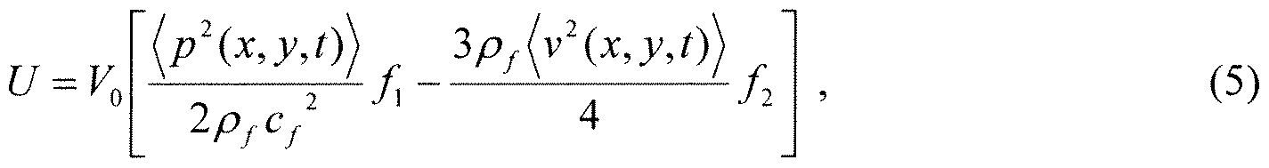
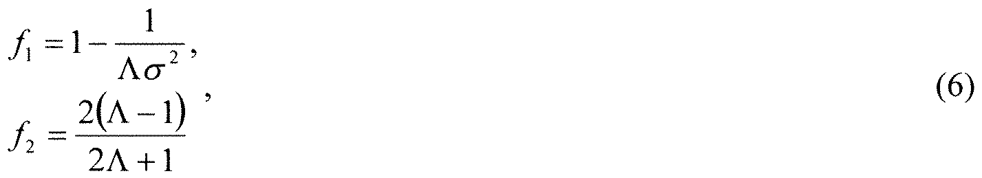
where p(x,y,z,t) is the acoustic pressure, v(x,y,z,t) is the fluid particle velocity, and < > denote time averages. V0 is the volume of the particle.
[0037] The diagram 100 of FIG. 1 shows the force required to separate small particles of various material properties. Each material has its own X parameter given in Equation [3]. In diagram 100, material properties (e.g. speed of sound, density) are used for the indicated material. The graph for bacteria spore is also valid for other materials of similar bulk modulus. Meaning smaller bacteria spore, very large protein clusters, and
polystyrene microspheres would all be in this category. The blood cell curve is for any cells of similar bulk modulus. Finally the hexane curve would be valid for any tiny drops of oil-like material with the radius indicated on the curve. These curves are for, as an example, 1 MHz applied acoustic frequency and an acoustic pressure of 0.5 MPa. These are easily achieved control variables. Higher frequency and higher pressure will afford better separation of smaller particles - down to 10s of nm.
[0038] Simulations regarding the current subject matter were run by plotting the following equation:
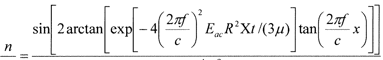
in(— x)
c
Where n is the number density of the suspended particulate, f is the frequency, c is the speed of sound, Eac is the energy density of the acoustic wave, R is the particle radius, X is the contrast factor, t is time, m is the dynamic viscosity of the fluid, and x is position in the standing wave. The equation describes the kinetics of the particles in the standing wave as a result of the action of the drag force and acoustic radiation force. This equation is derived in the paper by Feke et al.
[0039] The diagrams of FIGs. 5-10 plot the relative concentration, capture efficiency for different size particles of different densities and different frequencies. Along the x-axis is direction the particles travel from 0 to 2/2. The y-axis is the concentration relative to the initial of 1.
[0040] Diagram 500 of FIG. 5 shows the separation at 250 kHz for oil and an acoustic pressure amplitude of 250 kHz. Three particles sizes are shown; in black a 1 mm
radius particle, in green a 10 mm radius particle, and in red a 100 mm radius particle. We see that the large droplets are heavily concentrated at the pressure anti-nodal planes of the standing wave, whereas the intermediate and small particle have not undergone any appreciable concentration. This situation can be used to selectively concentrate and separate large particles, and exhibits size-exclusion behavior. Diagram 600 of FIG. 6 shows separation at 1 MHz for oil. Here one can see a concentration efficiency of much greater than 20: 1 for the intermediate and large droplets, and only minor changes for the small droplets. Finally, diagram 700 of Fig. 7 shows separation at 10 MHz, where the intermediate and small particles are heavily concentrated, but not the large ones. This is caused by the fact that the large particles are of the same order as the wavelength, and the acoustic radiation force is no longer effective. This is significant, because it shows a size-exclusion behavior that can be further exploited for preparation of very fine emulsions of biologically significant agents.
[0041] FIGs. 8-10 show analogous conditions for iron oxide (Fe02, a metal oxide simulant). Diagram 800 of FIG. 8 shows concentration at 250 kHz and 250 kPa for large, intermediate, and small particles of 100, 10, and 1 micron. We observe that particles with positive contrast move to the pressure nodes. It also shows that the large particles are concentrated significantly at the pressure nodes, and intermediate and smaller particles are not concentrated. Therefore, size-exclusion can work here as well. Diagram 900 of Fig. 9 shows the concentration at 1 MHz and 1 MPa, and shows that large and intermediate particles are concentrated but not small ones. Finally, diagram 1000 of Fig. 10 shows concentration at 10 MHz, where intermediate and small particles are concentrated. The large particles are of similar magnitude as the wavelength and do
not experience significant concentration. Analogous behavior is observed for micro- algae, bacteria, and blood cells. Like the oil case above, this is also significant because it demonstrates that the current subject matter can be applied for biotechnology applications for separating species of various sizes, essentially a high-flow, large-volume, size- exclusion separation technology. It also shows promise for lipid and platelet separation of blood.
[0042] As described above, two approaches to concentrating the particles through acoustic standing wave agglomeration (or coalescence). (1 ) The first approach as illustrated in FIG. 2 involves a series involves a parallel array of tube-shaped transducers. (2) The second approach as illustrated in FIG. 3 uses a series of flat acoustic transducers operating at 1 MHz and 10 MHz. Notwithstanding, it will be appreciated that other arrangements of acoustic transducers can be utilized.
[0043] The first implementation is shown in Figure 2 with further details in the diagram 1 100 of FIG. 1 1. With this arrangement, a multiphase-water mixture is pumped into the flow chamber 210 via the multi-phase water inlet 220 device from the where it encounters a parallel array of tube-shaped transducers 260 each operating at 1 - 10 MHz frequency. When the solution encounters the array of tube transducers 260 the agglomeration occurs and due to gravity the large clumps fall into the solids outlet 250 (e.g., a collection port, etc.). Any coalesced oil, or oil-like substances, will overcome buoyancy and self-transport to the respective low density outlet 230 on the top of the flow chamber 210. Diagram 1 100 of FIG. 1 1 shows pressure nodes in the tube-shaped transducer array 260.
[0044] With the second approach, as shown in FIG. 3, a multiphase- water mixture is pumped into the flow chamber 210 via the multi-phase water inlet 220 where it encounters a serial array of flat 1cm transducers 310 operating at a frequency range between 1 and 10 MHz. Like the first approach, when the solution encounters the array of tube transducers 310 the agglomeration occurs and due to gravity the large clumps fall into the solids outlet 250 (e.g., a collection port, etc.). Any coalesced oil, or oil-like substances, will overcome buoyancy and self- transport to the low density outlet 230 on the top of the flow chamber 210. As used herein, unless otherwise stated, the term outlet can comprise a piped exit from the flow chamber 210 or it can comprise a collection port requiring periodic removal of separated particulate.
[0045] While this specification contains many specifics, these should not be construed as limitations on the scope of what is claimed or of what may be claimed, but rather as descriptions of features specific to particular variations. Certain features that are described in this specification in the context of separate variations can also be
implemented in combination in a single variation. Conversely, various features that are described in the context of a single variation can also be implemented in multiple variations separately or in any suitable sub-combination. Moreover, although features may be described above as acting in certain combinations and even initially claimed as such, one or more features from a claimed combination can in some cases be excised from the combination, and the claimed combination may be directed to a subcombination or a variation of a sub-combination. Similarly, while operations are depicted in the drawings in a particular order, this should not be understood as requiring that such operations be performed in the particular order shown or in sequential order, or that all
illustrated operations be performed, to achieve desirable results. Only a few examples and implementations are disclosed. Variations, modifications and enhancements to the described examples and implementations and other implementations may be made based on what is disclosed.
Claims
1. An apparatus comprising:
a flow chamber through which is flowed a mixture of a fluid and a particulate, the flow chamber comprising:
at least one multi-phase water inlet through which multiphase water enters the flow chamber;
a water outlet through which water exits the flow chamber; a solids outlet through which particles having a density at or above a pre-defined threshold exit the flow chamber; and
a low density outlet through which particles having a density below the pre-defined threshold exit the flow chamber;
one or more ultrasonic transducers; and
one or more reflectors corresponding to each transducer;
wherein each transducer forms a standing acoustic wave at a different ultrasonic frequency and each ultrasonic frequency is optimized for a specific range of particle sizes to, along with a geometry of the flow chamber, selectively separate particles from the multi-phase water and water so that such particles exit the flow chamber via one of the solids outlet and the low density outlet.
2. An apparatus as in claim 1, wherein the one or more ultrasonic transducers operate at a frequency in a range of 1 MHz to 10 MHz.
3. An apparatus as in claim 1, wherein the one or more ultrasonic transducers operate at a frequency in a range of 100 kHz to 20 MHz
4. An apparatus as in claim 1 , wherein the one or more ultrasonic transducers are embedded in a wall of the flow chamber.
5. An apparatus as in claim 3, wherein the one or more ultrasonic transducers are arranged in a flat series.
6. An apparatus as in claim 1, wherein there are two or more ultrasonic transducers that are arranged in a parallel array within an inner portion of the flow chamber.
7. An apparatus as in claim 1 , wherein the flow chamber is vertically oriented with the low density outlet being on an upper portion and the solids outlet being on a lower portion.
8. An apparatus as in claim 1 wherein the flow chamber is horizontally oriented with the low density outlet being on the upper portion and the solids outlet being on the lower portion.
9. An apparatus as in claim 1 wherein the flow chamber is diagonally oriented with the low density outlet being on the upper incline and the solids outlet being on the lower incline.
10. An apparatus as in claim 6, wherein the multi-phase water inlet is disposed between the low density outlet and the two or more ultrasonic transducers.
1 1. An apparatus as in claim 6, wherein the multi-phase water inlet is at an acute angle from an outer wall of the flow chamber relative to the solids outlet.
12. An apparatus as in claim 7, wherein the water outlet is disposed between the two or more ultrasonic transducers and the solids outlet.
13. An apparatus as in claim 9, wherein the multi-phase water inlet is at an obtuse angle from an outer wall of the flow chamber relative to the solids outlet.
14. An apparatus as in claim 1, wherein the particles are selected from the group consisting of microalgae, yeast, fungi, bacteria, spores, gases or oils, metal oxides, metal particles, clays, dirt, plastics, and any particulate with a nonzero contrast factor.
15. An apparatus as in claim 1, wherein each transducer is optimized for a specific range of particles selected from the group consisting of microalgae, yeast, fungi, bacteria, spores, gases or oils, metal oxides, metal particles, clays, dirt, plastics, and any particulate with a non-zero contrast factor.
16. An apparatus as in claim 1 , wherein the one or more ultrasonic transducers each generate acoustic standing waves perpendicular, to the direction of the mean flow in the flow channel.
17. An apparatus as in claim 13, wherein the one or more acoustic standing waves have a horizontal orientation.
18. An apparatus as in claim 13, wherein the one or more acoustic standing waves have a vertical orientation.
19. An apparatus as in claim 13, wherein the one or more acoustic standing waves exert acoustic radiation force on the particulate for which the ultrasonic frequency is optimized for, such that the particulate is trapped in its corresponding acoustic standing wave against a fluid drag force, and wherein the particulate is concentrated in the acoustic field over time.
20. An apparatus as in claim 1, wherein the solids outlet is tapered.
21. An apparatus as in claim 1, wherein the flow chamber is oriented such that the multi-phase water is gravity fed from the multi-phase water inlet towards the solids outlet.
22. A method of separating particulate from a fluid comprising:
flowing the fluid past one or more positions within a flow chamber; and forming acoustic standing waves at the one or more positions, wherein each standing acoustic wave is maintained at a different ultrasonic frequency, wherein each ultrasonic frequency is optimized for a specific range of particle sizes and wherein particulate of the optimized size is trapped in its corresponding acoustic standing wave against the flow of the fluid, thereby concentrating the particulate in its corresponding acoustic standing wave; wherein the flow chamber comprises: at least one multi-phase water inlet through which multiphase water enters the flow chamber;
a water outlet through which water exits the flow chamber; a solids outlet through which particles having a density at or above a pre-defined threshold exit the flow chamber; and
a low density outlet through which particles having a density below the pre-defined threshold exit the flow chamber.
23. An apparatus comprising:
a flow chamber through which is flowed a mixture of a fluid and a particulate, the flow chamber comprising:
at least one multi-phase water inlet through which multiphase water enters the flow chamber; a water outlet through which water exits the flow chamber; a solids outlet through which agglomerated microorganisms and dirt exit the flow chamber; and
a low density outlet through which agglomerated oil droplets exit the flow chamber;
one or more ultrasonic transducers; and
one or more reflectors corresponding to each transducer;
wherein each transducer forms a standing acoustic wave at a different ultrasonic frequency and each ultrasonic frequency is optimized for a specific range of particle sizes to, along with a geometry of the flow chamber, selectively separate particles from the multi-phase water and water so that such particles exit the flow chamber via one of the solids outlet and the low density outlet.
Priority Applications (2)
| Application Number | Priority Date | Filing Date | Title |
|---|---|---|---|
| CA2846180A CA2846180A1 (en) | 2011-08-23 | 2012-08-22 | High-volume fast separation of multi-phase components in fluid suspensions |
| EP12825592.4A EP2748110B1 (en) | 2011-08-23 | 2012-08-22 | High-volume fast separation of multi-phase components in fluid suspensions |
Applications Claiming Priority (2)
| Application Number | Priority Date | Filing Date | Title |
|---|---|---|---|
| US13/216,049 | 2011-08-23 | ||
| US13/216,049 US9421553B2 (en) | 2010-08-23 | 2011-08-23 | High-volume fast separation of multi-phase components in fluid suspensions |
Publications (1)
| Publication Number | Publication Date |
|---|---|
| WO2013028726A1 true WO2013028726A1 (en) | 2013-02-28 |
Family
ID=47360835
Family Applications (1)
| Application Number | Title | Priority Date | Filing Date |
|---|---|---|---|
| PCT/US2012/051804 Ceased WO2013028726A1 (en) | 2011-08-23 | 2012-08-22 | High-volume fast separation of multi-phase components in fluid suspensions |
Country Status (4)
| Country | Link |
|---|---|
| US (2) | US9421553B2 (en) |
| EP (1) | EP2748110B1 (en) |
| CA (1) | CA2846180A1 (en) |
| WO (1) | WO2013028726A1 (en) |
Families Citing this family (69)
| Publication number | Priority date | Publication date | Assignee | Title |
|---|---|---|---|---|
| US8772004B2 (en) | 2009-06-25 | 2014-07-08 | Old Dominion University Research Foundation | System and method for high-voltage pulse assisted aggregation of algae |
| US8691145B2 (en) | 2009-11-16 | 2014-04-08 | Flodesign Sonics, Inc. | Ultrasound and acoustophoresis for water purification |
| US9421553B2 (en) | 2010-08-23 | 2016-08-23 | Flodesign Sonics, Inc. | High-volume fast separation of multi-phase components in fluid suspensions |
| US8679338B2 (en) | 2010-08-23 | 2014-03-25 | Flodesign Sonics, Inc. | Combined acoustic micro filtration and phononic crystal membrane particle separation |
| US8540798B2 (en) * | 2011-01-04 | 2013-09-24 | Guilherme Santana Lopes Gomes | Systems and methods for recycling steelmaking converter sludge |
| US9783775B2 (en) | 2012-03-15 | 2017-10-10 | Flodesign Sonics, Inc. | Bioreactor using acoustic standing waves |
| US9340435B2 (en) * | 2012-03-15 | 2016-05-17 | Flodesign Sonics, Inc. | Separation of multi-component fluid through ultrasonic acoustophoresis |
| US9458450B2 (en) | 2012-03-15 | 2016-10-04 | Flodesign Sonics, Inc. | Acoustophoretic separation technology using multi-dimensional standing waves |
| US9745548B2 (en) | 2012-03-15 | 2017-08-29 | Flodesign Sonics, Inc. | Acoustic perfusion devices |
| US10967298B2 (en) | 2012-03-15 | 2021-04-06 | Flodesign Sonics, Inc. | Driver and control for variable impedence load |
| US9688958B2 (en) | 2012-03-15 | 2017-06-27 | Flodesign Sonics, Inc. | Acoustic bioreactor processes |
| US9752114B2 (en) | 2012-03-15 | 2017-09-05 | Flodesign Sonics, Inc | Bioreactor using acoustic standing waves |
| US9567559B2 (en) | 2012-03-15 | 2017-02-14 | Flodesign Sonics, Inc. | Bioreactor using acoustic standing waves |
| US10689609B2 (en) | 2012-03-15 | 2020-06-23 | Flodesign Sonics, Inc. | Acoustic bioreactor processes |
| US9822333B2 (en) | 2012-03-15 | 2017-11-21 | Flodesign Sonics, Inc. | Acoustic perfusion devices |
| US10322949B2 (en) | 2012-03-15 | 2019-06-18 | Flodesign Sonics, Inc. | Transducer and reflector configurations for an acoustophoretic device |
| US9272234B2 (en) | 2012-03-15 | 2016-03-01 | Flodesign Sonics, Inc. | Separation of multi-component fluid through ultrasonic acoustophoresis |
| US10704021B2 (en) | 2012-03-15 | 2020-07-07 | Flodesign Sonics, Inc. | Acoustic perfusion devices |
| US9752113B2 (en) * | 2012-03-15 | 2017-09-05 | Flodesign Sonics, Inc. | Acoustic perfusion devices |
| US10953436B2 (en) | 2012-03-15 | 2021-03-23 | Flodesign Sonics, Inc. | Acoustophoretic device with piezoelectric transducer array |
| US9950282B2 (en) | 2012-03-15 | 2018-04-24 | Flodesign Sonics, Inc. | Electronic configuration and control for acoustic standing wave generation |
| US10370635B2 (en) | 2012-03-15 | 2019-08-06 | Flodesign Sonics, Inc. | Acoustic separation of T cells |
| US9738866B2 (en) * | 2012-03-15 | 2017-08-22 | Flodesign Sonics, Inc. | Acoustic perfusion devices |
| US9796956B2 (en) | 2013-11-06 | 2017-10-24 | Flodesign Sonics, Inc. | Multi-stage acoustophoresis device |
| US10737953B2 (en) | 2012-04-20 | 2020-08-11 | Flodesign Sonics, Inc. | Acoustophoretic method for use in bioreactors |
| US11324873B2 (en) | 2012-04-20 | 2022-05-10 | Flodesign Sonics, Inc. | Acoustic blood separation processes and devices |
| US8673154B2 (en) | 2012-07-12 | 2014-03-18 | Heliae Development, Llc | Tunable electrical field for aggregating microorganisms |
| US8709250B2 (en) | 2012-07-12 | 2014-04-29 | Heliae Development, Llc | Tubular electro-acoustic aggregation device |
| US8668827B2 (en) | 2012-07-12 | 2014-03-11 | Heliae Development, Llc | Rectangular channel electro-acoustic aggregation device |
| US8709258B2 (en) | 2012-07-12 | 2014-04-29 | Heliae Development, Llc | Patterned electrical pulse microorganism aggregation |
| US8702991B2 (en) | 2012-07-12 | 2014-04-22 | Heliae Development, Llc | Electrical microorganism aggregation methods |
| US9192944B2 (en) * | 2012-09-30 | 2015-11-24 | Arizona Board Of Regents, A Body Corporate Of The State Of Arizona Acting For And On Behalf Of Arizona State University | Methods, systems and apparatus for size-based particle separation |
| US9745569B2 (en) | 2013-09-13 | 2017-08-29 | Flodesign Sonics, Inc. | System for generating high concentration factors for low cell density suspensions |
| US9320995B2 (en) * | 2013-09-17 | 2016-04-26 | Covaris, Inc. | Method and apparatus for processing sample material |
| US9766168B2 (en) * | 2013-10-23 | 2017-09-19 | Applied Research Associates, Inc. | Acoustic particulate concentration methods and system |
| CN105939767B (en) | 2014-01-08 | 2018-04-06 | 弗洛设计声能学公司 | Sound electrophoretic apparatus with alliteration electrophoresis chamber |
| DE102014204645A1 (en) * | 2014-03-13 | 2015-09-17 | Siemens Aktiengesellschaft | Device for treating a liquid containing oil droplets |
| US9744483B2 (en) | 2014-07-02 | 2017-08-29 | Flodesign Sonics, Inc. | Large scale acoustic separation device |
| SG11201610712XA (en) | 2014-07-02 | 2017-01-27 | Flodesign Sonics Inc | Acoustophoretic device with uniform fluid flow |
| JP2017534446A (en) | 2014-10-24 | 2017-11-24 | ライフ テクノロジーズ コーポレイション | Acoustic precipitation liquid-liquid sample purification system |
| US10106770B2 (en) | 2015-03-24 | 2018-10-23 | Flodesign Sonics, Inc. | Methods and apparatus for particle aggregation using acoustic standing waves |
| US11377651B2 (en) | 2016-10-19 | 2022-07-05 | Flodesign Sonics, Inc. | Cell therapy processes utilizing acoustophoresis |
| US11021699B2 (en) | 2015-04-29 | 2021-06-01 | FioDesign Sonics, Inc. | Separation using angled acoustic waves |
| US11708572B2 (en) | 2015-04-29 | 2023-07-25 | Flodesign Sonics, Inc. | Acoustic cell separation techniques and processes |
| CN107921332A (en) | 2015-04-29 | 2018-04-17 | 弗洛设计超声波公司 | Acoustophoresis device for oblique wave particle deflection |
| US10640760B2 (en) | 2016-05-03 | 2020-05-05 | Flodesign Sonics, Inc. | Therapeutic cell washing, concentration, and separation utilizing acoustophoresis |
| WO2016187596A1 (en) | 2015-05-20 | 2016-11-24 | Flodesign Sonics, Inc. | Acoustic manipulation of particles in standing wave fields |
| WO2016201385A2 (en) | 2015-06-11 | 2016-12-15 | Flodesign Sonics, Inc. | Acoustic methods for separation cells and pathogens |
| US9663756B1 (en) | 2016-02-25 | 2017-05-30 | Flodesign Sonics, Inc. | Acoustic separation of cellular supporting materials from cultured cells |
| EP3319739B1 (en) | 2015-07-09 | 2021-03-31 | Flodesign Sonics Inc. | Non-planar and non-symmetrical piezolectric crystals and reflectors |
| US11459540B2 (en) | 2015-07-28 | 2022-10-04 | Flodesign Sonics, Inc. | Expanded bed affinity selection |
| US11474085B2 (en) | 2015-07-28 | 2022-10-18 | Flodesign Sonics, Inc. | Expanded bed affinity selection |
| US11938421B2 (en) | 2016-03-06 | 2024-03-26 | WindplusSonne GmbH | Method and device for separating and/or cleaning aerosols and solid material particles and fibers from gases as well as solid material particles and fibers from liquid materials by acoustophoresis |
| CA3017528A1 (en) * | 2016-04-14 | 2017-09-21 | Bart Lipkens | Multi-stage acoustophoresis device |
| US10710006B2 (en) | 2016-04-25 | 2020-07-14 | Flodesign Sonics, Inc. | Piezoelectric transducer for generation of an acoustic standing wave |
| US11085035B2 (en) | 2016-05-03 | 2021-08-10 | Flodesign Sonics, Inc. | Therapeutic cell washing, concentration, and separation utilizing acoustophoresis |
| US11214789B2 (en) | 2016-05-03 | 2022-01-04 | Flodesign Sonics, Inc. | Concentration and washing of particles with acoustics |
| CN107876209B (en) * | 2016-09-30 | 2021-11-30 | 爱科来株式会社 | Method, apparatus and system for separating particles |
| WO2018075830A1 (en) | 2016-10-19 | 2018-04-26 | Flodesign Sonics, Inc. | Affinity cell extraction by acoustics |
| CN107014476B (en) * | 2017-03-07 | 2019-07-05 | 中国石油大学(华东) | A method of utilizing sound pressure amplitudes in acoustic levitation drop measurement liquid |
| SE541075C2 (en) * | 2017-03-10 | 2019-03-26 | The Packaging Greenhouse Ab | Ultrasound-assisted separation |
| CN114900773A (en) | 2017-12-14 | 2022-08-12 | 弗洛设计声能学公司 | Acoustophoretic system, method for operating acoustophoretic system, and method for controlling acoustic transducer and acoustic system |
| US11579143B2 (en) | 2018-05-23 | 2023-02-14 | Covaris, Llc | Acoustic based cell separation |
| DE102018008259A1 (en) * | 2018-10-18 | 2020-04-23 | Smart Material Printing B.V. | Filter systems for suspended particles with particle sizes from 400 pm to ≤500 μm and their use |
| US11291939B1 (en) | 2021-07-13 | 2022-04-05 | Smart Material Printing B.V. | Ultra-fine particle aggregation, neutralization and filtration |
| JP7617823B2 (en) * | 2021-08-26 | 2025-01-20 | アークレイ株式会社 | Particle recovery device and particle recovery method |
| US11986835B2 (en) * | 2021-12-10 | 2024-05-21 | Mage Llc | Method and apparatus for self-contained fluid cleaning apparatus |
| US12325645B2 (en) | 2021-12-10 | 2025-06-10 | Mage Llc | Systems and methods for freshwater production and brine waste recovery |
| US12005388B2 (en) | 2022-07-26 | 2024-06-11 | Smart Material Printing B.V. | Apparatus and methods for air filtration of HVAC systems |
Citations (9)
| Publication number | Priority date | Publication date | Assignee | Title |
|---|---|---|---|---|
| US4523682A (en) | 1982-05-19 | 1985-06-18 | The United States Of America As Represented By The Administrator Of The National Aeronautics And Space Administration | Acoustic particle separation |
| US5085783A (en) | 1990-08-16 | 1992-02-04 | Case Western Reserve University | Acoustically driven particle separation method and apparatus |
| WO1998050133A1 (en) | 1997-05-03 | 1998-11-12 | University College Cardiff Consultants Ltd. | Particle manipulation |
| WO2000041794A1 (en) | 1999-01-15 | 2000-07-20 | University College Cardiff Consultants Ltd. | Particle manipulation |
| US20080217259A1 (en) * | 2004-09-24 | 2008-09-11 | Spectronic Ab | Method and Device for Separating Particles |
| US20090226994A1 (en) | 2005-07-07 | 2009-09-10 | Fraunhofer-Gesellschaft Zur Forderung Der Angewandten Forschung E.V. | Method and Device for Acoustic Manipulation of Particles, Cells and Viruses |
| US20100206818A1 (en) * | 2009-02-19 | 2010-08-19 | Chartered Semiconductor Manufacturing, Ltd. | Ultrasonic filtration for cmp slurry |
| US20110123392A1 (en) * | 2009-11-16 | 2011-05-26 | Flodesign, Inc. | Ultrasound and acoustophoresis for water purification |
| US20110154890A1 (en) * | 2008-10-08 | 2011-06-30 | Foss Analytical A/S | Separation of particles in liquids by use of a standing ultrasonic wave |
Family Cites Families (167)
| Publication number | Priority date | Publication date | Assignee | Title |
|---|---|---|---|---|
| US2473971A (en) | 1944-02-25 | 1949-06-21 | Donald E Ross | Underwater transducer |
| US2667944A (en) | 1949-12-10 | 1954-02-02 | Combustion Eng | Cyclone separator |
| US3372370A (en) | 1965-09-22 | 1968-03-05 | Aquasonics Engineering Company | Electroacoustic transducer |
| US3555311A (en) | 1969-01-23 | 1971-01-12 | Marquardt Corp | High pressure piezoelectric transducer |
| US4158629A (en) | 1974-08-12 | 1979-06-19 | Vernon D. Beehler | Dynamic self-cleaning filter for liquids |
| US4204096A (en) | 1974-12-02 | 1980-05-20 | Barcus Lester M | Sonic transducer mounting |
| US4055491A (en) | 1976-06-02 | 1977-10-25 | Porath Furedi Asher | Apparatus and method for removing fine particles from a liquid medium by ultrasonic waves |
| US4065875A (en) | 1976-09-17 | 1978-01-03 | University Of Delaware | Selective destruction of certain algae |
| JPS6034433B2 (en) | 1977-03-07 | 1985-08-08 | 株式会社豊田中央研究所 | ultrasonic transducer |
| US4118649A (en) | 1977-05-25 | 1978-10-03 | Rca Corporation | Transducer assembly for megasonic cleaning |
| US4165273A (en) | 1977-12-20 | 1979-08-21 | Azarov Nikolai N | Device for producing deeply desalted water |
| US4320659A (en) | 1978-02-27 | 1982-03-23 | Panametrics, Inc. | Ultrasonic system for measuring fluid impedance or liquid level |
| CA1141629A (en) | 1979-07-31 | 1983-02-22 | Roger F. Potts | Machine for cleaning plastic containers |
| FR2485858B1 (en) | 1980-06-25 | 1986-04-11 | Commissariat Energie Atomique | METHOD FOR MANUFACTURING ULTRASONIC TRANSDUCERS OF COMPLEX SHAPES AND APPLICATION TO OBTAINING ANNULAR TRANSDUCERS |
| DE3027433A1 (en) | 1980-07-19 | 1982-02-18 | Messerschmitt-Bölkow-Blohm GmbH, 8000 München | Pressure diffusion sepn. method for mixts. - uses perpendicular identical frequency wave fields with differing phases |
| US5834871A (en) | 1996-08-05 | 1998-11-10 | Puskas; William L. | Apparatus and methods for cleaning and/or processing delicate parts |
| JPH0679682B2 (en) | 1983-10-31 | 1994-10-12 | ブリティッシュ・テクノロジー・グループ・リミテッド | Method and apparatus for separating particulate matter in a liquid medium |
| CN85100483B (en) | 1985-04-01 | 1988-10-19 | 上海灯泡厂 | Backing material for ultrasonic transducer |
| US4666595A (en) | 1985-09-16 | 1987-05-19 | Coulter Electronics, Inc. | Apparatus for acoustically removing particles from a magnetic separation matrix |
| US4759775A (en) | 1986-02-21 | 1988-07-26 | Utah Bioresearch, Inc. | Methods and apparatus for moving and separating materials exhibiting different physical properties |
| US4983189A (en) | 1986-02-21 | 1991-01-08 | Technical Research Associates, Inc. | Methods and apparatus for moving and separating materials exhibiting different physical properties |
| US4699588A (en) | 1986-03-06 | 1987-10-13 | Sonotech, Inc. | Method and apparatus for conducting a process in a pulsating environment |
| GB8612759D0 (en) | 1986-05-27 | 1986-07-02 | Unilever Plc | Manipulating particulate matter |
| AT389235B (en) | 1987-05-19 | 1989-11-10 | Stuckart Wolfgang | METHOD FOR CLEANING LIQUIDS BY MEANS OF ULTRASOUND AND DEVICES FOR CARRYING OUT THIS METHOD |
| US4821838A (en) | 1987-10-30 | 1989-04-18 | Hewlett-Packard Company | Acoustic damper |
| JPH01134216A (en) | 1987-11-19 | 1989-05-26 | Agency Of Ind Science & Technol | Visualizing method for three-dimensional standing wave sound field |
| US4836684A (en) | 1988-02-18 | 1989-06-06 | Ultrasonic Power Corporation | Ultrasonic cleaning apparatus with phase diversifier |
| AT390739B (en) | 1988-11-03 | 1990-06-25 | Ewald Dipl Ing Dr Benes | METHOD AND DEVICE FOR SEPARATING PARTICLES DISPERSED IN A DISPERSION AGENT |
| GB9005705D0 (en) | 1990-03-14 | 1990-05-09 | Health Lab Service Board | Particle manipulation |
| GB2265004B (en) | 1992-03-10 | 1996-01-10 | Univ Cardiff | Immuno-agglutination assay using ultrasonic standing wave field |
| CA2133823C (en) | 1992-04-06 | 2002-10-15 | Norman D.G. Mountford | Ultrasonic treatment of liquids in particular metal melts |
| JP2890011B2 (en) | 1992-08-19 | 1999-05-10 | 富士写真フイルム株式会社 | Information recording method |
| US6216538B1 (en) | 1992-12-02 | 2001-04-17 | Hitachi, Ltd. | Particle handling apparatus for handling particles in fluid by acoustic radiation pressure |
| AT398707B (en) | 1993-05-11 | 1995-01-25 | Trampler Felix | MULTILAYER PIEZOELECTRIC RESONATOR FOR THE SEPARATION OF SUSPENDED PARTICLES |
| WO1994026390A1 (en) * | 1993-05-11 | 1994-11-24 | Carlson, David, V. | Multilayered piezoelectric resonator for the separation of suspended particles |
| US5626767A (en) | 1993-07-02 | 1997-05-06 | Sonosep Biotech Inc. | Acoustic filter for separating and recycling suspended particles |
| US5443985A (en) | 1993-07-22 | 1995-08-22 | Alberta Research Council | Cell culture bioreactor |
| US5431817A (en) | 1993-09-13 | 1995-07-11 | W. R. Grace & Co.-Conn. | Bleach resistant polysulfone/polyurethane composite membranes |
| US5395592A (en) | 1993-10-04 | 1995-03-07 | Bolleman; Brent | Acoustic liquid processing device |
| US5452267A (en) | 1994-01-27 | 1995-09-19 | Magnetrol International, Inc. | Midrange ultrasonic transducer |
| EP0764265A4 (en) | 1994-06-07 | 1998-05-20 | Univ Boston | Acoustic detection of particles |
| US5560362A (en) | 1994-06-13 | 1996-10-01 | Acuson Corporation | Active thermal control of ultrasound transducers |
| JP3487699B2 (en) | 1995-11-08 | 2004-01-19 | 株式会社日立製作所 | Ultrasonic treatment method and apparatus |
| JP3875736B2 (en) | 1995-11-14 | 2007-01-31 | 株式会社協和エクシオ | Wastewater treatment method and apparatus |
| JP2700058B2 (en) | 1996-01-23 | 1998-01-19 | 工業技術院長 | Non-contact micromanipulation method using ultrasonic waves |
| US5688405A (en) | 1996-02-28 | 1997-11-18 | The United States Of America As Represented By The Secretary Of The Navy | Method and apparatus for separating particulate matter from a fluid |
| NL1003595C2 (en) | 1996-04-10 | 1997-10-14 | Tno | Method and device for characterizing suspensions. |
| DE19648519C2 (en) | 1996-11-23 | 2000-11-16 | Preussag Wassertechnik Gmbh | Process and system for material separation by means of membrane filtration |
| US5951456A (en) | 1997-05-16 | 1999-09-14 | Scott; Harold W. | Ultrasonic methods and apparatus for separating materials in a fluid mixture |
| US6326213B1 (en) | 1998-02-09 | 2001-12-04 | The Boards Of Govenors For Higher Education, State Of Rhode Island And Providence Plantations | Acoustic standing-wave enhancement of a fiber-optic Salmonella biosensor |
| DE19820466C2 (en) | 1998-05-07 | 2002-06-13 | Fraunhofer Ges Forschung | Device and method for the targeted exposure of a biological sample to sound waves |
| JP2000024431A (en) | 1998-07-14 | 2000-01-25 | Hitachi Ltd | Particle processing equipment |
| US6090295A (en) | 1998-08-11 | 2000-07-18 | University Technology Corporation | Method and apparatus for acoustically demixing aqueous solutions |
| US7981368B2 (en) | 1998-10-28 | 2011-07-19 | Covaris, Inc. | Method and apparatus for acoustically controlling liquid solutions in microfluidic devices |
| AU1175899A (en) * | 1998-11-20 | 2000-06-13 | Proudo Co., Ltd. | Method of treating liquid, liquid treatment apparatus, and liquid treatment system |
| US6166231A (en) | 1998-12-15 | 2000-12-26 | Martek Biosciences Corporation | Two phase extraction of oil from biomass |
| CN1181337C (en) | 2000-08-08 | 2004-12-22 | 清华大学 | Method for manipulating solid molecules in microfluidic system and related kits |
| US6592821B1 (en) | 1999-05-17 | 2003-07-15 | Caliper Technologies Corp. | Focusing of microparticles in microfluidic systems |
| US6314974B1 (en) | 1999-06-28 | 2001-11-13 | Fairchild Semiconductor Corporation | Potted transducer array with matching network in a multiple pass configuration |
| GB9916851D0 (en) | 1999-07-20 | 1999-09-22 | Univ Wales Bangor | Manipulation of particles in liquid media |
| AUPQ629100A0 (en) | 2000-03-16 | 2000-04-15 | Btf Pty Ltd | Process for preparing controlled samples of particles such as microorganisms and cells |
| CA2409716C (en) | 2000-05-16 | 2010-11-30 | Atrionix, Inc. | Apparatus and method incorporating an ultrasound transducer onto a delivery member |
| US6395186B1 (en) | 2000-06-20 | 2002-05-28 | Delaware Capital Formation, Inc. | Pressure liquid filtration with ultrasonic bridging prevention |
| AU2001288447A1 (en) | 2000-08-28 | 2002-03-13 | Ocean Power Corporation | Method for pretreating water for desalination |
| CN100495030C (en) | 2000-09-30 | 2009-06-03 | 清华大学 | Multi-force operator and use thereof |
| WO2002050511A2 (en) | 2000-12-18 | 2002-06-27 | E.I. Du Pont De Nemours And Company | Method and apparatus for ultrasonic sizing of particles in suspensions |
| SE522801C2 (en) | 2001-03-09 | 2004-03-09 | Erysave Ab | Apparatus for separating suspended particles from an ultrasonic fluid and method for such separation |
| SE0103013D0 (en) | 2001-03-09 | 2001-09-12 | Erysave Ab Ideon | System and method of treatment of whole blood |
| US6467350B1 (en) | 2001-03-15 | 2002-10-22 | The Regents Of The University Of California | Cylindrical acoustic levitator/concentrator |
| US6770248B2 (en) | 2001-05-04 | 2004-08-03 | Her Majesty The Queen In Right Of Canada, As Represented By The Minister Of National Defence Of Her Majesty's Canadian Government | Flowthrough device for the ultrasonic destruction of microorganisms in fluids |
| US6763722B2 (en) | 2001-07-13 | 2004-07-20 | Transurgical, Inc. | Ultrasonic transducers |
| US6551248B2 (en) | 2001-07-31 | 2003-04-22 | Koninklijke Philips Electronics N.V. | System for attaching an acoustic element to an integrated circuit |
| DE10148916A1 (en) | 2001-10-04 | 2003-04-17 | Beatrix Christa Meier | Ultrasonic head assembly, to break down cells, comprises a piezo element to generate ultrasonic waves which are carried through intermediate elements to a sonotrode for direct delivery into the samples in a micro-titration plate |
| US6487095B1 (en) | 2001-10-31 | 2002-11-26 | International Business Machines Corporation | Multiphase zero-volt-switching resonant DC-DC regulator |
| US6649069B2 (en) | 2002-01-23 | 2003-11-18 | Bae Systems Information And Electronic Systems Integration Inc | Active acoustic piping |
| US7061163B2 (en) | 2002-01-28 | 2006-06-13 | Matsushita Electric Industrial Co., Ltd. | Ultrasonic transducer and ultrasonic flowmeter |
| US6749666B2 (en) | 2002-04-26 | 2004-06-15 | Board Of Regents, The University Of Texas System | Modulated acoustic aggiomeration system and method |
| GB2408276B (en) | 2002-06-03 | 2006-01-25 | Shell Int Research | Downhole desalination of aquifer water |
| WO2003102737A2 (en) * | 2002-06-04 | 2003-12-11 | Protasis Corporation | Method and device for ultrasonically manipulating particles within a fluid |
| US20040016699A1 (en) | 2002-07-29 | 2004-01-29 | Michael Bayevsky | Systems and methods for ultrasonic cleaning of cross-flow membrane filters |
| GB0221391D0 (en) | 2002-09-16 | 2002-10-23 | Secr Defence | Apparatus for directing particles in a fluid |
| GB0222421D0 (en) | 2002-09-27 | 2002-11-06 | Ratcliff Henry K | Advanced ultrasonic processor |
| US7108137B2 (en) | 2002-10-02 | 2006-09-19 | Wisconsin Alumni Research Foundation | Method and apparatus for separating particles by size |
| US7191787B1 (en) | 2003-02-03 | 2007-03-20 | Lam Research Corporation | Method and apparatus for semiconductor wafer cleaning using high-frequency acoustic energy with supercritical fluid |
| US7601267B2 (en) | 2003-03-06 | 2009-10-13 | Albrecht Haake | Method for positioning small particles in a fluid |
| US7008540B1 (en) | 2003-04-07 | 2006-03-07 | The Ohio State University | Ultrasonically cleaned membrane filtration system |
| US6990852B2 (en) | 2003-07-28 | 2006-01-31 | Becton Dickinson & Company | System and method for detecting particles |
| CN1245231C (en) | 2003-08-27 | 2006-03-15 | 中国石油化工股份有限公司 | Method and device for breaking oil water emulsion using combined action of forward current and countercurrent flow ultrasonic wave |
| US7541166B2 (en) | 2003-09-19 | 2009-06-02 | Microfluidic Systems, Inc. | Sonication to selectively lyse different cell types |
| US7232016B2 (en) | 2003-12-08 | 2007-06-19 | General Motors Corporation | Fluid damper having continuously variable damping response |
| US7445716B2 (en) | 2004-01-05 | 2008-11-04 | Eaton Lp | Crossflow pressure liquid filtration with ultrasonic enhancement |
| US8012355B2 (en) | 2004-01-30 | 2011-09-06 | Pss Acquisitionco Llc | Molecular separator |
| US7044737B2 (en) | 2004-03-05 | 2006-05-16 | Liang Fu | Ultrasound oral hygiene and therapeutic device |
| US7340957B2 (en) | 2004-07-29 | 2008-03-11 | Los Alamos National Security, Llc | Ultrasonic analyte concentration and application in flow cytometry |
| US20080272034A1 (en) | 2004-08-16 | 2008-11-06 | Searete Llc, | Separation of particles from a fluid by wave action |
| AT413655B (en) | 2004-08-19 | 2006-04-15 | Felix Dipl Ing Dr Trampler | DEVICE FOR DISPERSING DISPERSED PARTICLES |
| GB2420510B (en) | 2004-11-25 | 2010-10-06 | Cyclotech Ltd | Methods and apparatus for conditioning and degassing liquids and gases in suspension |
| CN101443444A (en) | 2004-12-29 | 2009-05-27 | 比奥根艾迪克Ma公司 | Bioreactor process control system and method |
| US7704743B2 (en) | 2005-03-30 | 2010-04-27 | Georgia Tech Research Corporation | Electrosonic cell manipulation device and method of use thereof |
| JP4770251B2 (en) | 2005-04-25 | 2011-09-14 | パナソニック株式会社 | Component separation device and component separation method using the same |
| US20100193407A1 (en) | 2006-01-19 | 2010-08-05 | Yeda Research And Development Co., Ltd. | Device and Method For Particle Manipulation in Fluid |
| BRPI0708470A2 (en) | 2006-03-14 | 2011-05-31 | Merck & Co Inc | process for the production of crystalline particles of an organic active compound, and, pharmaceutical composition |
| CN1843945A (en) | 2006-05-16 | 2006-10-11 | 徐小宁 | Seawater desalination treatment system utilizing jet-flow technology |
| US7763177B2 (en) | 2006-10-26 | 2010-07-27 | Atlantium Technologies Ltd. | System and method for ultrasonic cleaning of ultraviolet disinfection system |
| JP4984849B2 (en) | 2006-11-27 | 2012-07-25 | パナソニック株式会社 | Component separation device and chemical analysis device using the component separation device |
| US7673516B2 (en) | 2006-12-28 | 2010-03-09 | Kimberly-Clark Worldwide, Inc. | Ultrasonic liquid treatment system |
| CA2679042C (en) | 2007-03-02 | 2015-11-24 | Smith & Nephew Plc | Apparatus and method for filter cleaning by ultrasound, backwashing and filter movement during the filtration of biological samples |
| DE102008006501B4 (en) | 2007-03-19 | 2013-05-16 | Sonja Lauterborn | Combined ultrasonic air backwashing process for the chemical-free in-situ cleaning of submerged membranes during backwashing during operation |
| EP2479552B1 (en) | 2007-04-02 | 2015-09-02 | Acoustic Cytometry Systems, Inc. | Methods for enhanced analysis of acoustic field focused cells and particles |
| US8083068B2 (en) | 2007-04-09 | 2011-12-27 | Los Alamos National Security, Llc | Apparatus for separating particles utilizing engineered acoustic contrast capture particles |
| US7837040B2 (en) | 2007-04-09 | 2010-11-23 | Los Alamos National Security, Llc | Acoustic concentration of particles in fluid flow |
| US8273302B2 (en) | 2007-05-15 | 2012-09-25 | Panasonic Corporation | Component separation device |
| GB0716047D0 (en) | 2007-08-16 | 2007-09-26 | Welding Inst | Acoustic transducer assembley |
| JP5119848B2 (en) | 2007-10-12 | 2013-01-16 | 富士ゼロックス株式会社 | Microreactor device |
| WO2009063198A2 (en) | 2007-11-14 | 2009-05-22 | Prokyma Technologies Limited | Extraction and purification of biological cells using ultrasound |
| ES2326109B1 (en) | 2007-12-05 | 2010-06-25 | Consejo Superior De Investigaciones Cientificas | SELECTIVE AND NON INVASIVE SEPARATION AND EXTRACTION MICRODISPOSITIVE OF PARTICLES IN POLIDISPERSE SUSPENSIONS, MANUFACTURING PROCEDURE AND ITS APPLICATIONS. |
| US8266951B2 (en) | 2007-12-19 | 2012-09-18 | Los Alamos National Security, Llc | Particle analysis in an acoustic cytometer |
| US8714014B2 (en) * | 2008-01-16 | 2014-05-06 | Life Technologies Corporation | System and method for acoustic focusing hardware and implementations |
| US9480935B2 (en) | 2008-02-01 | 2016-11-01 | Lawrence Livermore National Security, Llc | Systems and methods for separating particles and/or substances from a sample fluid |
| JP2011513791A (en) | 2008-03-03 | 2011-04-28 | スリーエム イノベイティブ プロパティズ カンパニー | Process for audible acoustic frequency management in gas flow systems. |
| US8319398B2 (en) | 2008-04-04 | 2012-11-27 | Microsonic Systems Inc. | Methods and systems to form high efficiency and uniform fresnel lens arrays for ultrasonic liquid manipulation |
| US8054145B2 (en) | 2008-04-30 | 2011-11-08 | Georgia Tech Research Corporation | Phononic crystal wave structures |
| CA2725483A1 (en) | 2008-05-27 | 2009-12-03 | Kolmir Water Tech Ltd. | Apparatus and method for treatment of a contaminated water-based fluid |
| DE102008002210A1 (en) | 2008-06-04 | 2009-12-10 | Evonik Degussa Gmbh | Process for the fermentative production of erythropoietin |
| WO2009149519A1 (en) | 2008-06-12 | 2009-12-17 | Winwick Business Solutions Pty Ltd | System for cultivation and processing of microorganisms and products therefrom |
| US7935259B2 (en) | 2008-07-03 | 2011-05-03 | The United States Of America As Represented By The Administrator Of The National Aeronautics And Space Administration | Filtering apparatus and method of use |
| CN106215451A (en) | 2008-07-18 | 2016-12-14 | 普罗索尼克斯有限公司 | For the method improving degree of crystallinity |
| US8387803B2 (en) | 2008-08-26 | 2013-03-05 | Ge Healthcare Bio-Sciences Ab | Particle sorting |
| US8865003B2 (en) | 2008-09-26 | 2014-10-21 | Abbott Laboratories | Apparatus and method for separation of particles suspended in a liquid from the liquid in which they are suspended |
| US20100140185A1 (en) | 2008-12-05 | 2010-06-10 | John Hill | Wastewater treatment |
| JP2010252785A (en) | 2009-03-31 | 2010-11-11 | Kanagawa Acad Of Sci & Technol | Cell concentration separator |
| US8476060B2 (en) | 2009-04-13 | 2013-07-02 | Board Of Regents, The University Of Texas System | Process for separating lipids from a biomass |
| US20110095225A1 (en) | 2009-04-20 | 2011-04-28 | Origin Oil, Inc. | Systems, apparatuses, and methods for extracting non-polar lipids from an aqueous algae slurry and lipids produced therefrom |
| US8865452B2 (en) | 2009-06-15 | 2014-10-21 | Aurora Algae, Inc. | Systems and methods for extracting lipids from wet algal biomass |
| US8772004B2 (en) | 2009-06-25 | 2014-07-08 | Old Dominion University Research Foundation | System and method for high-voltage pulse assisted aggregation of algae |
| AU2010266035B2 (en) | 2009-06-26 | 2015-02-12 | Talfryn S.A. | Integrated system and process for bioproduct production |
| GB0914762D0 (en) | 2009-08-24 | 2009-09-30 | Univ Glasgow | Fluidics apparatus and fluidics substrate |
| KR101695049B1 (en) | 2009-08-26 | 2017-01-10 | 지이 헬스케어 바이오-사이언시즈 코프. | Continuous recovery harvest bag |
| GB0915072D0 (en) | 2009-09-01 | 2009-09-30 | Prokyma Technologies Ltd | Ultrasound & magnetic method |
| DE102009046145A1 (en) | 2009-10-29 | 2011-05-12 | Robert Bosch Gmbh | Ultrasonic transducer for use in a fluid medium |
| CA2819583A1 (en) | 2009-12-03 | 2011-06-09 | Bard Holding, Inc. | Process and system for producing algal oil |
| US8518681B2 (en) | 2009-12-04 | 2013-08-27 | Sound Surgical Technologies Llc | Selective lysing of cells using ultrasound |
| JP5878164B2 (en) | 2010-04-12 | 2016-03-08 | フローデザイン ソニックス, インコーポレイテッド | Ultrasonic and acoustophoretic techniques for water-oil separation for use in producing water |
| US8889388B2 (en) | 2010-04-21 | 2014-11-18 | Zhaowei Wang | Acoustic device and methods thereof for separation and concentration |
| PT105058B (en) | 2010-04-21 | 2013-04-17 | Hovione Farmaciencia S A | PROCESS FOR PROCESSING OF PARTICLES OF PHARMACEUTICAL ACTIVE INGREDIENTS |
| US8714360B2 (en) | 2010-05-12 | 2014-05-06 | Ethicon Endo-Surgery, Inc. | Tissue processing device with ultrasonic tissue particle separator |
| JP5688451B2 (en) | 2010-06-04 | 2015-03-25 | エンパイア テクノロジー ディベロップメント エルエルシー | Acoustically driven nanoparticle concentrator |
| WO2011159957A2 (en) | 2010-06-16 | 2011-12-22 | Flodesign Sonics, Inc. | Phononic crystal desalination system and method of use |
| GB201010724D0 (en) | 2010-06-25 | 2010-08-11 | Isis Innovation | Acoustic separators |
| WO2012009320A2 (en) | 2010-07-15 | 2012-01-19 | Advanced Liquid Logic, Inc. | Systems for and methods of promoting cell lysis in droplet actuators |
| US9421553B2 (en) | 2010-08-23 | 2016-08-23 | Flodesign Sonics, Inc. | High-volume fast separation of multi-phase components in fluid suspensions |
| US9011699B2 (en) | 2010-08-23 | 2015-04-21 | Flodesign Sonics, Inc. | Ultrasonic agglomeration of microalgae |
| US8592204B2 (en) | 2010-08-23 | 2013-11-26 | Flodesign Sonics, Inc. | Ultrasound and acoustophoresis for collection and processing of oleaginous microorganisms |
| US8679338B2 (en) | 2010-08-23 | 2014-03-25 | Flodesign Sonics, Inc. | Combined acoustic micro filtration and phononic crystal membrane particle separation |
| GB2486680A (en) | 2010-12-22 | 2012-06-27 | Morgan Electro Ceramics Ltd | Ultrasonic or acoustic transducer that supports two or more frequencies |
| US9314751B2 (en) | 2011-01-07 | 2016-04-19 | Life Technologies Corporation | Methods and apparatus for mixing and shipping fluids |
| US9376655B2 (en) | 2011-09-29 | 2016-06-28 | Life Technologies Corporation | Filter systems for separating microcarriers from cell culture solutions |
| US8256076B1 (en) | 2011-11-19 | 2012-09-04 | Murray F Feller | Method of making an ultrasonic transducer |
| US9458450B2 (en) | 2012-03-15 | 2016-10-04 | Flodesign Sonics, Inc. | Acoustophoretic separation technology using multi-dimensional standing waves |
| US10040011B2 (en) | 2012-03-15 | 2018-08-07 | Flodesign Sonics, Inc. | Acoustophoretic multi-component separation technology platform |
| AU2013249071B2 (en) | 2012-04-20 | 2017-05-04 | Flodesign Sonics Inc. | Acoustophoretic separation of lipid particles from red blood cells |
| US9718708B2 (en) | 2012-04-20 | 2017-08-01 | Flodesign Sonics Inc. | Acoustophoretic enhanced system for use in tanks |
| US8709250B2 (en) | 2012-07-12 | 2014-04-29 | Heliae Development, Llc | Tubular electro-acoustic aggregation device |
| WO2014014941A1 (en) | 2012-07-16 | 2014-01-23 | Flodesign Sonics, Inc. | Improved separation of multi-component fluid through ultrasonic acoustophoresis |
| CN105143835B (en) | 2012-10-02 | 2019-06-28 | 弗洛设计声能学公司 | Acoustophoretic separation technique using multidimensional standing waves |
| EP2953700B1 (en) | 2013-02-07 | 2021-04-07 | Flodesign Sonics Inc. | Bioreactor using acoustic standing waves |
| WO2014176559A1 (en) | 2013-04-25 | 2014-10-30 | Flodesign Sonics, Inc. | Excipient removal from pharmacological samples |
-
2011
- 2011-08-23 US US13/216,049 patent/US9421553B2/en not_active Expired - Fee Related
-
2012
- 2012-08-22 WO PCT/US2012/051804 patent/WO2013028726A1/en not_active Ceased
- 2012-08-22 EP EP12825592.4A patent/EP2748110B1/en not_active Not-in-force
- 2012-08-22 CA CA2846180A patent/CA2846180A1/en active Pending
-
2016
- 2016-08-23 US US15/245,044 patent/US10071383B2/en active Active
Patent Citations (9)
| Publication number | Priority date | Publication date | Assignee | Title |
|---|---|---|---|---|
| US4523682A (en) | 1982-05-19 | 1985-06-18 | The United States Of America As Represented By The Administrator Of The National Aeronautics And Space Administration | Acoustic particle separation |
| US5085783A (en) | 1990-08-16 | 1992-02-04 | Case Western Reserve University | Acoustically driven particle separation method and apparatus |
| WO1998050133A1 (en) | 1997-05-03 | 1998-11-12 | University College Cardiff Consultants Ltd. | Particle manipulation |
| WO2000041794A1 (en) | 1999-01-15 | 2000-07-20 | University College Cardiff Consultants Ltd. | Particle manipulation |
| US20080217259A1 (en) * | 2004-09-24 | 2008-09-11 | Spectronic Ab | Method and Device for Separating Particles |
| US20090226994A1 (en) | 2005-07-07 | 2009-09-10 | Fraunhofer-Gesellschaft Zur Forderung Der Angewandten Forschung E.V. | Method and Device for Acoustic Manipulation of Particles, Cells and Viruses |
| US20110154890A1 (en) * | 2008-10-08 | 2011-06-30 | Foss Analytical A/S | Separation of particles in liquids by use of a standing ultrasonic wave |
| US20100206818A1 (en) * | 2009-02-19 | 2010-08-19 | Chartered Semiconductor Manufacturing, Ltd. | Ultrasonic filtration for cmp slurry |
| US20110123392A1 (en) * | 2009-11-16 | 2011-05-26 | Flodesign, Inc. | Ultrasound and acoustophoresis for water purification |
Non-Patent Citations (7)
| Title |
|---|
| B. LIPKENSJ. DIONNEA. TRASKB. SZCZURA. STEVENSE. RIETMAN: "Separation of micron-sized particles in macro-scale cavities by ultrasonic standing waves", PRESENTED AT THE INTERNATIONAL CONGRESS ON ULTRASONICS, 11 January 2009 (2009-01-11) |
| B. LIPKENSJ. DIONNEA. TRASKB. SZCZURE. RIETMAN: "Prediction and measurement of particle velocities in ultrasonic standing waves", J. ACOUST. SOC. AM., vol. 124, no. 4, pages 2492 |
| B. LIPKENSJ. DIONNEM. COSTOLOA. STEVENSE. RIETMAN: "Separation of bacterial spores from flowing water in macro-scale cavities by ultrasonic standing waves", ARXIV, June 2010 (2010-06-01) |
| B. LIPKENSM. COSTOLOE. RIETMAN: "The effect of frequency sweeping and fluid flow on particle trajectories in ultrasonic standing waves", IEEE SENSORS JOURNAL, vol. 8, no. 6, 2008, pages 667 - 677, XP011215548 |
| L. P. GOR'KOV: "On the forces acting on a small particle in an acoustical field in an ideal fluid", SOV. PHYS. DOKL., vol. 6, 1962, pages 773 - 775, XP055628803 |
| LIPKENSJ. DIONNEM. COSTOLOE. RIETMAN: "Frequency sweeping and fluid flow effects on particle trajectories in ultrasonic standing waves", ACOUSTICS 08, 29 June 2008 (2008-06-29) |
| See also references of EP2748110A4 * |
Also Published As
| Publication number | Publication date |
|---|---|
| US20120325727A1 (en) | 2012-12-27 |
| US20160368000A1 (en) | 2016-12-22 |
| EP2748110A4 (en) | 2015-05-27 |
| US9421553B2 (en) | 2016-08-23 |
| CA2846180A1 (en) | 2013-02-28 |
| EP2748110A1 (en) | 2014-07-02 |
| EP2748110B1 (en) | 2021-01-06 |
| US10071383B2 (en) | 2018-09-11 |
Similar Documents
| Publication | Publication Date | Title |
|---|---|---|
| US10071383B2 (en) | High-volume fast separation of multi-phase components in fluid suspensions | |
| US9695063B2 (en) | Combined acoustic micro filtration and phononic crystal membrane particle separation | |
| EP2558179B1 (en) | Use of ultrasound and acoustophoresis technology for separation of particulates from a host medium | |
| EP3200892B1 (en) | Acoustophoretic clarification of particle-laden non-flowing fluids | |
| US9340435B2 (en) | Separation of multi-component fluid through ultrasonic acoustophoresis | |
| US9272234B2 (en) | Separation of multi-component fluid through ultrasonic acoustophoresis | |
| US20150321129A1 (en) | Acoustophoretic device with piezoelectric transducer array | |
| WO2014014941A1 (en) | Improved separation of multi-component fluid through ultrasonic acoustophoresis | |
| US20200017376A1 (en) | Methods and apparatuses for separation of biologic particles and/or oil from fluids using acoustics | |
| WO2017193085A1 (en) | Acoustophoretic clarification of particle-laden non-flowing fluids |
Legal Events
| Date | Code | Title | Description |
|---|---|---|---|
| 121 | Ep: the epo has been informed by wipo that ep was designated in this application |
Ref document number: 12825592 Country of ref document: EP Kind code of ref document: A1 |
|
| ENP | Entry into the national phase |
Ref document number: 2846180 Country of ref document: CA |
|
| NENP | Non-entry into the national phase |
Ref country code: DE |