WO2010053054A1 - Dispositif de station de base sans fil et dispositif de terminal mobile - Google Patents
Dispositif de station de base sans fil et dispositif de terminal mobile Download PDFInfo
- Publication number
- WO2010053054A1 WO2010053054A1 PCT/JP2009/068672 JP2009068672W WO2010053054A1 WO 2010053054 A1 WO2010053054 A1 WO 2010053054A1 JP 2009068672 W JP2009068672 W JP 2009068672W WO 2010053054 A1 WO2010053054 A1 WO 2010053054A1
- Authority
- WO
- WIPO (PCT)
- Prior art keywords
- signal
- channel signal
- downlink
- mobile communication
- communication system
- Prior art date
Links
- 238000010295 mobile communication Methods 0.000 claims abstract description 77
- 239000000969 carrier Substances 0.000 claims abstract description 36
- 230000005540 biological transmission Effects 0.000 claims description 80
- 230000007274 generation of a signal involved in cell-cell signaling Effects 0.000 claims description 39
- 238000000034 method Methods 0.000 claims description 22
- 238000000605 extraction Methods 0.000 description 9
- 238000000926 separation method Methods 0.000 description 8
- 239000000284 extract Substances 0.000 description 6
- 238000004891 communication Methods 0.000 description 5
- 238000010586 diagram Methods 0.000 description 4
- 238000011144 upstream manufacturing Methods 0.000 description 4
- 101001139126 Homo sapiens Krueppel-like factor 6 Proteins 0.000 description 2
- 238000012986 modification Methods 0.000 description 2
- 230000004048 modification Effects 0.000 description 2
- 101000710013 Homo sapiens Reversion-inducing cysteine-rich protein with Kazal motifs Proteins 0.000 description 1
- 101000661807 Homo sapiens Suppressor of tumorigenicity 14 protein Proteins 0.000 description 1
- 108010076504 Protein Sorting Signals Proteins 0.000 description 1
- 230000002776 aggregation Effects 0.000 description 1
- 238000004220 aggregation Methods 0.000 description 1
- 108090000237 interleukin-24 Proteins 0.000 description 1
- 230000007774 longterm Effects 0.000 description 1
- 238000013468 resource allocation Methods 0.000 description 1
- 230000011664 signaling Effects 0.000 description 1
Images


Classifications
-
- H—ELECTRICITY
- H04—ELECTRIC COMMUNICATION TECHNIQUE
- H04J—MULTIPLEX COMMUNICATION
- H04J11/00—Orthogonal multiplex systems, e.g. using WALSH codes
- H04J11/0069—Cell search, i.e. determining cell identity [cell-ID]
- H04J11/0083—Multi-mode cell search, i.e. where several modes or systems can be used, e.g. backwards compatible, dual mode or flexible systems
-
- H—ELECTRICITY
- H04—ELECTRIC COMMUNICATION TECHNIQUE
- H04L—TRANSMISSION OF DIGITAL INFORMATION, e.g. TELEGRAPHIC COMMUNICATION
- H04L5/00—Arrangements affording multiple use of the transmission path
- H04L5/003—Arrangements for allocating sub-channels of the transmission path
- H04L5/0053—Allocation of signalling, i.e. of overhead other than pilot signals
-
- H—ELECTRICITY
- H04—ELECTRIC COMMUNICATION TECHNIQUE
- H04W—WIRELESS COMMUNICATION NETWORKS
- H04W74/00—Wireless channel access
- H04W74/002—Transmission of channel access control information
- H04W74/006—Transmission of channel access control information in the downlink, i.e. towards the terminal
-
- H—ELECTRICITY
- H04—ELECTRIC COMMUNICATION TECHNIQUE
- H04W—WIRELESS COMMUNICATION NETWORKS
- H04W74/00—Wireless channel access
- H04W74/08—Non-scheduled access, e.g. ALOHA
- H04W74/0833—Random access procedures, e.g. with 4-step access
Definitions
- the present invention relates to a radio base station apparatus and a mobile terminal apparatus in a next generation mobile communication system.
- UMTS Universal Mobile Telecommunications System
- WSDPA High Speed Downlink Packet Access
- HSUPA High Speed Uplink Packet Access
- CDMA Wideband Code Division Multiple Access
- LTE Long Term Evolution
- OFDMA Orthogonal Frequency Division Multiple Access
- SC-FDMA Single Carrier Frequency Multiple Access
- the third generation system can achieve a maximum transmission rate of about 2 Mbps on the downlink using generally a fixed bandwidth of 5 MHz.
- a maximum transmission rate of about 300 Mbps on the downlink and about 75 Mbps on the uplink can be realized using a variable band of 1.4 MHz to 20 MHz.
- LTE-A LTE Advanced
- the present invention has been made in view of this point, and an object of the present invention is to provide a radio base station apparatus and a mobile terminal apparatus corresponding to each mobile communication system when a plurality of mobile communication systems coexist.
- the radio base station apparatus of the present invention is unique to the first mobile communication system with respect to at least one downlink component carrier in the first mobile communication system having a relatively wide first system band composed of a plurality of component carriers. And a synchronization for a second mobile communication system having a relatively narrow second system band for one downlink component carrier that does not multiplex a synchronization channel signal unique to the first mobile communication system. It further comprises synchronization channel signal generation means for generating a channel signal, and transmission means for transmitting a control signal including the synchronization channel signal.
- the radio base station apparatus of the present invention is relatively narrow with respect to at least one downlink component carrier in the first mobile communication system having a relatively wide first system band composed of a plurality of component carriers.
- a synchronization channel signal generating means for generating a synchronization channel signal for a second mobile communication system having two system bands and not generating a synchronization channel signal for other downlink component carriers, and a control signal including the synchronization channel signal are transmitted Transmitting means.
- a mobile terminal apparatus is unique to the first mobile communication system, multiplexed on at least one downlink component carrier in a first mobile communication system having a relatively wide first system band composed of a plurality of component carriers.
- Cell search means for performing a cell search using a synchronization channel signal of the mobile station, and a center for controlling a reception center frequency of a downlink signal based on information of a downlink component carrier including a synchronization channel signal unique to the first mobile communication system subjected to the cell search And a frequency control means.
- the mobile terminal apparatus of the present invention provides a relatively narrow first component multiplexed on at least one downlink component carrier in a first mobile communication system having a relatively wide first system band composed of a plurality of component carriers.
- cell search means for performing a cell search using a synchronization channel signal for a second mobile communication system having two system bands, and downlink component carrier information including the cell search for the synchronization channel signal for the second mobile communication system
- Center frequency control means for controlling the reception center frequency of the downlink signal.
- System-specific synchronization channel signal and / or relatively narrow multiplexed on at least one downlink component carrier in the first mobile communication system having a relatively wide first system band composed of a plurality of component carriers After performing a cell search using the synchronization channel signal for the second mobile communication system having the second system band, information on the downlink component carrier including the synchronization channel signal used for the cell search and broadcast from the radio base station apparatus
- Uplink component included in broadcast information Since the random access in the vertical component carriers assigned based on information in Yaria, when a plurality of mobile communication systems coexists, it can also be corresponding to each of the mobile communication system. In particular, corresponding to each mobile communication system, initial access can be performed with a reduced control delay between the radio base station apparatus and the mobile terminal apparatus.
- FIG. 1 is a diagram for explaining a frequency usage state when mobile communication is performed in the downlink.
- An example shown in FIG. 1 is an LTE-A system, which is a first mobile communication system having a relatively wide first system band composed of a plurality of component carriers, and a relatively narrow (here, one component carrier).
- This is a frequency use state when an LTE system, which is a second mobile communication system having a second system band (consisting of 2), coexists.
- LTE-A system for example, wireless communication is performed with a variable system bandwidth of 100 MHz or less, and in the LTE system, wireless communication is performed with a variable system bandwidth of 20 MHz or less.
- the system band of the LTE-A system is at least one fundamental frequency region (component carrier: CC) having the system band of the LTE system as a unit.
- component carrier component carrier
- Mobile terminal apparatus having a system band of 20 MHz (base band).
- the frequency band allocated to the downlink and the frequency band allocated to the uplink are asymmetric.
- uplink (UL) and downlink (DL) have an asymmetric bandwidth in one transmission time interval (TTI)
- time division In duplex (TDD) a plurality of uplinks are allocated to the downlink bandwidth, and the uplink (UL) and the downlink (DL) have an asymmetric bandwidth.
- the processing procedure used in the LTE system cannot cope with a system in which the uplink (UL) and the downlink (DL) have an asymmetric bandwidth. For this reason, even a system that can use a widened frequency band can only deal with the fundamental frequency region, and cannot effectively use the widened frequency band.
- each component carrier uses a synchronization channel (SCH) signal or a broadcast channel (Broadcast) used in the LTE system.
- Channel: BCH) signal is multiplexed.
- the synchronization channel signal is searched while scanning the frequency, for example, scanning from the low frequency side to the high frequency side. For this reason, if a synchronization channel signal used in the LTE system is multiplexed on each component carrier, a cell search is performed with the synchronization channel signal of the component carrier scanned first, and the component carrier is always detected. Become.
- the frequency is moved from the component carrier detected by the cell search at the stage of starting communication to a different component carrier.
- the control information include RRC (Radio Resource Control) signaling.
- RRC Radio Resource Control
- the present inventors have come up with the present invention in order to solve this problem. That is, the gist of the present invention is the mobile terminal apparatus, wherein the first terminal component multiplexed in at least one downlink component carrier in the first mobile communication system having a relatively wide first system band composed of a plurality of component carriers.
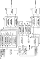
- FIG. 3 is a block diagram showing a configuration of the radio base station apparatus according to the embodiment of the present invention.
- the radio base station apparatus shown in FIG. 3 includes a transmission system processing unit and a reception system processing unit.
- the transmission system processing unit includes a control signal generation unit 101 that generates a downlink component carrier (downlink CC) control signal, a downlink L1 / L2 control signal generation unit 102 that generates a downlink control signal (layer 1 / layer 2 control signal), and A downlink shared channel signal generation unit 103 that generates a downlink shared channel signal, and a downlink CC signal multiplexing unit that multiplexes downlink CC signals (control signal, downlink L1 / L2 control signal, downlink shared channel signal) for each downlink CC.
- downlink CC downlink component carrier
- L1 / L2 control signal generation unit 102 that generates a downlink control signal (layer 1 / layer 2 control signal)
- a downlink shared channel signal generation unit 103 that generates a
- the control signal generation unit 101 includes, for each CC, an SCH signal generation unit 1011 that generates an SCH signal (synchronization channel signal), a PBCH signal generation unit 1012 that generates a PBCH signal (broadcast channel signal), and broadcast information (Dynamic Broadcast).
- DBCH signal generation unit 1013 for generating a channel (DBCH) signal, RACH (Random Access Channel) response signal, RACH response signal for generating a control signal (MAC (Media Access Control) / RRC signal), MAC / RRC control signal generation Unit 1014 and an SCH / BCH signal control unit 1015 that controls generation of an SCH signal, a PBCH signal, and a DBCH signal generated according to the propagation environment between the radio base station apparatus and the mobile terminal apparatus.
- the reception system processing unit includes a multiple CC signal demultiplexing unit 106 that demultiplexes uplink reception signals into multiple CC signals, an intra-CC signal demultiplexing unit 107 that demultiplexes signals in individual uplink CCs, and an uplink control signal (layer 1 / layer 2 control signal), an uplink L1 / L2 control signal receiver 108, an uplink shared channel signal receiver 109 that receives an uplink shared channel signal, and an uplink CC RACH receiver that receives the RACH signal of each uplink CC. 110.
- a multiple CC signal demultiplexing unit 106 that demultiplexes uplink reception signals into multiple CC signals
- an intra-CC signal demultiplexing unit 107 that demultiplexes signals in individual uplink CCs
- an uplink control signal layer 1 / layer 2 control signal
- an uplink L1 / L2 control signal receiver 108 an uplink shared channel signal receiver 109 that receives an uplink shared channel signal
- an uplink CC RACH receiver
- the radio base station apparatus includes a pair band allocation control unit 111 that controls allocation of the downlink component carrier and the uplink component carrier (pair band) from the capability information of the mobile terminal apparatus, and includes the pair band allocation information.
- a shared channel scheduler 112 that schedules shared channels.
- SCH signal generation section 1011 generates a synchronization channel signal for cell search in the mobile terminal apparatus.
- the SCH signal generated by the SCH signal generation unit 1011 is multiplexed with other signals by the downlink CC signal multiplexing unit 104.
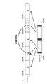
- the SCH signal generation unit 1011 generates an LTE-A system-specific synchronization channel signal for at least one downlink CC in the LTE-A system, and does not multiplex an LTE-A system-specific synchronization channel signal. In contrast, a synchronization channel signal for the LTE system is generated. That is, as shown in FIG. 4 (a), LTE-A system-specific SCH signal A is multiplexed on at least one CC, and LTE-A system-specific SCH signal A is not multiplexed on one CC.
- the SCH signal B is multiplexed.
- LTE is transmitted to all CCs (CC # 1, CC # 2, CC # 4, CC # 5) other than the CC (CC # 3) that multiplexes the SCH signal B for the LTE system.
- the SCH signal A specific to the A system is multiplexed is shown, the present invention is not limited to this, and the LTE-A system specific to at least one CC other than the CC that multiplexes the SCH signal B for the LTE system
- the SCH signal A may be multiplexed.
- 4A shows the case where the LTE system SCH signal B is multiplexed on CC # 3, the present invention is not limited to this, and the LTE system SCH signal B is You may multiplex to CC.
- the SCH signal unique to the LTE-A system is an SCH signal that cannot be searched by a mobile terminal device corresponding to the LTE system.
- an SCH signal B for example, an SCH signal having a configuration / sequence different from the LTE system SCH signal B (specifically, an SCH signal in which the type of the Zad-off sequence is different), an LTE system SCH An SCH signal mapped to a time position different from the signal B, an SCH signal mapped to a frequency position different from the SCH signal B for LTE system, an SCH signal multiplied by a scramble sequence unique to the LTE-A system, and the like.
- the SCH signal generation section 1011 generates an LTE system synchronization channel signal for at least one downlink CC in the LTE-A system and does not generate a synchronization channel signal for other downlink CCs. That is, as shown in FIG. 4B, the LTE system SCH signal B is multiplexed on at least one (here, one) downlink CC (CC # 3), and another downlink CC (CC # 1, no SCH signal is generated for CC # 2, CC # 4, CC # 5). 4B shows the case where the LTE system SCH signal B is multiplexed on CC # 3, the present invention is not limited to this, and the LTE system SCH signal B is You may multiplex to CC and may multiplex to several CC.
- the PBCH signal generation unit 1012 generates a broadcast channel signal (PBCH signal) including information such as the CC bandwidth, the number of antennas, the bandwidth of the CC that can be received by the DBCH (accessible CC) and the center frequency.
- PBCH signal broadcast channel signal
- the generated PBCH signal is multiplexed with other signals in downlink CC signal multiplexing section 104.
- the PBCH signal generation unit 1012 generates a broadcast channel signal specific to the LTE-A system for at least one downlink CC in the LTE-A system and one downlink CC that does not multiplex a broadcast channel signal specific to the LTE-A system. In contrast, a broadcast channel signal for the LTE system is generated. That is, as shown in FIG. 4A, the LTE system specific PBCH signal A is multiplexed to at least one CC, and the LTE system specific PBCH signal A is not multiplexed to the LTE system. PBCH signal B is multiplexed.
- all CCs (CC # 1, CC # 2, CC # 4, CC # 5) other than the CC (CC # 3) that multiplexes the PBCH signal B for the LTE system are LTE.
- the PBCH signal A specific to the A system is multiplexed is shown, the present invention is not limited to this and is specific to the LTE-A system in at least one CC other than the CC that multiplexes the PBCH signal B for the LTE system.
- the PBCH signal A may be multiplexed.
- FIG. 4A shows a case where the LTE system PBCH signal B is multiplexed on CC # 3.
- the present invention is not limited to this, and the LTE system PBCH signal B may be any You may multiplex to CC.
- the PBCH signal unique to the LTE-A system is a PBCH signal that cannot be received by a mobile terminal apparatus corresponding to the LTE system.
- a PBCH signal B for example, a PBCH signal having a configuration / sequence different from that of the LTE system PBCH signal B, a PBCH signal mapped at a different time position from the LTE system PBCH signal B, and an LTE system PBCH signal B PBCH signals mapped to different frequency positions, PBCH signals multiplied by a scramble sequence unique to the LTE-A system, and the like.
- the DBCH signal generation unit 1013 converts uplink CC information (bandwidth and center frequency of uplink CC to be paired, bandwidth and center frequency of accessible CC, etc.) to be paired with downlink CC (initial downlink CC) into DBCH signal ( Broadcast channel signal). Also, the DBCH signal generation unit 1013 includes carrier set information (total bandwidth of aggregated CCs or the number of aggregated CCs and the center frequency thereof) related to the initial downlink CC, and a mobile terminal corresponding to LTE-A. The center frequency of the CC to which the device-specific RACH parameter and / or paging information unique to the mobile terminal device corresponding to LTE-A is transmitted is generated as a DBCH signal (broadcast channel signal). The generated DBCH signal is multiplexed with other signals in downlink CC signal multiplexing section 104.
- the RACH response signal / MAC / RRC control signal generator 1014 generates a RACH response signal that is a response signal of the RACH signal (preamble) and a control signal (MAC / RRC control signal).
- the control signal includes pair band allocation information of the downlink CC and the uplink CC sent from the shared channel scheduler 112.
- the generated RACH response signal and MAC / RRC control signal are multiplexed with other signals in downlink CC signal multiplexing section 104.
- the SCH / BCH signal control unit 1015 allocates downlink component carriers that multiplex a synchronization channel signal and / or broadcast channel signal unique to the LTE-A system, or assigns downlink component carriers that do not multiplex a synchronization channel signal and / or broadcast channel signal. It is a control signal assigning means to assign. That is, the SCH / BCH signal control unit 1015 does not multiplex the SCH or BCH (PBCH) specific to the LTE-A system with respect to which CC, or does not multiplex the SCH or BCH (PBCH) with respect to which CC. (Whether to transmit SCH or BCH (PBCH)). Thus, the radio base station apparatus determines which CC to multiplex the SCH and BCH specific to the LTE-A system and / or which CC to multiplex the SCH and BCH. Can be determined arbitrarily.
- predetermined CCs may always be used, and adaptively according to the propagation environment between the radio base station apparatus and the mobile terminal apparatus. You may control to. In this case, based on the number of connected mobile terminals in each component carrier, the amount of interference power of each component carrier, the data load amount in each component carrier, and / or the path loss (distance attenuation) between the radio base station apparatus and the mobile terminal apparatus, It is preferable to change the CC to be adaptively assigned. Thus, when changing CC to allocate adaptively, a radio base station apparatus may control autonomously distributedly.
- the downlink L1 / L2 control signal generation unit 102 generates a downlink L1 / L2 control signal based on the schedule determined by the shared channel scheduler 112.
- the generated downlink L1 / L2 control signal is multiplexed with other signals by the downlink CC signal multiplexing unit 104.
- the downlink shared channel signal generation unit 103 Based on the schedule determined by the shared channel scheduler 112, the downlink shared channel signal generation unit 103 generates a downlink shared channel signal using downlink transmission data from an upper layer.
- the generated downlink shared channel signal is multiplexed with other signals by downlink CC signal multiplexing section 104.
- the uplink L1 / L2 control signal reception unit 108 receives the uplink L1 / L2 control signal separated by the uplink CC signal separation unit 107 based on the schedule determined by the shared channel scheduler 112.
- the uplink shared channel signal reception unit 109 receives the uplink shared channel signal separated by the uplink CC signal separation unit 107 based on the schedule determined by the shared channel scheduler 112.
- This uplink shared channel signal includes information on the transmission / reception bandwidth of the mobile terminal apparatus in the uplink CC that is a pair of the initial downlink CC including the synchronization channel signal used for the cell search.
- uplink transmission data is sent to an upper layer, and the transmission / reception bandwidth information (UE capability information) is sent to the pair band allocation control unit 111.
- the pair band allocation control unit 111 generates uplink CC and downlink CC band allocation information based on the UE capability information, and sends the pair band allocation information to the shared channel scheduler 112. For example, if the transmission / reception bandwidth of a mobile terminal apparatus that allocates a pair band with UE capability information is 40 MHz, the uplink CC is set to 40 MHz, the downlink CC is determined to be a predetermined bandwidth (for example, 60 MHz), A pair band of the downlink CC is determined (pair band assignment).
- the shared channel scheduler 112 performs transmission / reception scheduling of the vertical control signal and the vertical shared channel. Further, the shared channel scheduler 112 sends the pair band allocation information to the RACH response signal / MAC / RRC control signal generation unit 1014.
- the uplink CC RACH signal receiving unit 110 receives the RACH signal of each CC separated by the uplink CC signal separation unit 107.
- This RACH signal includes identification information of the LTE-A system.
- the uplink CC RACH signal reception unit 110 sends the uplink CC and RACH signal reception sequence that received the RACH signal together with the RACH parameter to the shared channel scheduler 112.
- the shared channel scheduler 112 identifies the initial downlink CC and schedules transmission / reception of the upper / lower shared channel signal and the upper / lower control signal by using the information of the uplink CC and the RACH signal reception sequence that received the RACH signal.
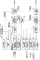
- FIG. 5 is a block diagram showing a configuration of the mobile terminal apparatus according to the embodiment of the present invention.
- the mobile terminal apparatus shown in FIG. 5 includes a reception system processing unit and a transmission system processing unit.
- the reception system processing unit separates the downlink reception signal from the downlink reception center frequency control unit 201 that controls the downlink reception center frequency, the downlink reception signal bandwidth extraction unit 202 that is a reception filter that extracts the bandwidth of the downlink reception signal, and A received downlink signal separator 203, an SCH signal receiver (cell search unit) 204 that receives a synchronization channel signal, a PBCH signal receiver 205 that receives a PBCH signal, and an initial downlink CC that receives an initial CC control signal.
- SCH signal receiver cell search unit
- a control signal receiving unit 206 an SCH / BCH signal receiving method control unit 207 for controlling the receiving method of the SCH signal and / or BCH signal, and a downlink L1 / L2 control signal receiving unit 208 for receiving the downlink L1 / L2 control signal;
- a downlink shared channel signal receiving unit 209 that receives the downlink shared channel signal.
- the initial downlink CC control signal receiving unit 206 is a DBCH signal receiving unit 2061 that receives a broadcast information (DBCH) signal, a RACH response signal, a RACH response signal that receives a control signal (MAC / RRC signal), and a MAC / RRC control signal.
- a receiving unit 2062 receives a broadcast information (DBCH) signal, a RACH response signal, a RACH response signal that receives a control signal (MAC / RRC signal), and a MAC / RRC control signal.
- the transmission system processing unit includes an uplink L1 / L2 control signal generation unit 210 that generates an uplink control signal, an uplink shared channel signal generation unit 211 that generates an uplink shared channel signal, and a RACH that generates a random access channel (RACH) signal.
- Signal generator 212 uplink transmission signal multiplexer 213 that multiplexes uplink transmission signals, uplink transmission signal bandwidth limiter 214 that is a transmission filter that limits the bandwidth of uplink transmission signals, and controls the uplink transmission center frequency And an uplink transmission center frequency control unit 215.
- the mobile terminal apparatus includes a pair band allocation information storage unit 216 that stores allocation information of downlink component carriers and uplink component carriers (pair bands).
- the downlink reception center frequency control unit 201 receives information on the center frequency of the downlink component carrier (initial downlink CC) at the time of cell search in the SCH signal reception unit 204 from the SCH signal reception unit 204, and uses the information on the center frequency as the information on the center frequency. Based on this, the downlink reception center frequency is controlled (moved). Further, the downlink reception center frequency control unit 201 controls (moves) the downlink reception center frequency based on the allocation information of the downlink CC and the uplink CC. This controlled downlink reception center frequency information is sent to the downlink reception signal bandwidth extraction unit 202.
- the downlink reception center frequency control unit 201 receives information on the center frequency of the accessible CC in the PBCH signal from the PBCH signal reception unit 205, and controls (moves) the downlink reception center frequency based on the center frequency information. . Further, the downlink reception center frequency control unit 201 receives information on the center frequency of the accessible CC in the DBCH signal from the DBCH signal reception unit 2061, and controls (moves) the downlink reception center frequency based on the information on the center frequency. .
- the downlink reception signal bandwidth extraction unit 202 includes initial downlink CC information included in the broadcast channel signal (PBCH signal) received by the PBCH signal reception unit 205, that is, among information such as the initial downlink CC bandwidth and the number of antennas. Based on the information on the bandwidth of the initial downlink CC, the bandwidth of the downlink reception signal is extracted. The reception signal filtered in this way is sent to the downlink reception signal separation section 203. Further, the downlink reception signal bandwidth extraction unit 202 extracts the bandwidth of the downlink reception signal based on the allocation information of the downlink CC and the uplink CC. Specifically, the received signal is filtered by the reception filter set to the bandwidth of the initial downlink CC (or accessible CC) using the downlink reception center frequency.
- PBCH signal broadcast channel signal
- the downlink reception signal separation unit 203 separates the downlink reception signal into an SCH signal, a BCH signal (PBCH signal, a DBCH signal), a downlink control signal (L1 / L2 control signal), and a downlink shared channel signal. Then, downlink reception signal separation section 203 sends a PBCH signal to PBCH signal reception section 205, sends a downlink L1 / L2 control signal to downlink L1 / L2 control signal reception section 208, and receives a downlink shared channel signal as a downlink shared channel signal. Output to the unit 209. The downlink shared channel signal output to the downlink shared channel signal receiving unit 209 is sent to the upper layer as downlink received data.
- the downlink reception signal separation unit 203 When receiving the initial downlink CC control signal as the downlink reception signal in the initial access, the downlink reception signal separation unit 203 separates it into a broadcast information signal (DBCH signal), a RACH response signal, and a MAC / RRC control signal. Then, downlink reception signal separation section 203 sends a broadcast information signal (DBCH signal) to DBCH signal reception section 2061, and outputs a RACH response signal and MAC / RRC control signal to RACH response signal and MAC / RRC control signal reception section 2062. To do.
- DBCH signal broadcast information signal
- RACH response signal a broadcast information signal
- MAC / RRC control signal MAC / RRC control signal
- the SCH signal reception unit 204 performs a cell search using an SCH signal included in any one of a plurality of downlink CCs. As shown in FIG. 4A, when there are a downlink CC that multiplexes the SCH signal A unique to the LTE-A system and a downlink CC that multiplexes the SCH signal B for the LTE system, the SCH signal reception unit 204 The cell search may be performed using the SCH signal A unique to the LTE-A system, or the cell search may be performed using the SCH signal B for the LTE system. The SCH signal A and the LTE system specific to the LTE-A system The cell search may be performed using both of the SCH signals B for use.
- a carrier search is performed at a frequency raster interval from a low carrier frequency.
- the carrier search may be stopped when the SCH signal is received.
- the carrier search may be performed at a frequency raster interval from a low carrier frequency, and a plurality of SCH signals of a plurality of CCs may be received in order.
- the SCH signal reception unit 204 is for the LTE system.
- Cell search using the SCH signal B In the cell search when the SCH signal B for LTE system is multiplexed on a plurality of CCs, for example, the carrier search is performed at a frequency raster interval from a low carrier frequency, and the SCH signal in a certain CC is received.
- the carrier search may be stopped at this point, for example, a carrier search may be performed at a frequency raster interval from a low carrier frequency, and a plurality of SCH signals of a plurality of CCs may be received in order.
- a frequency block including an SCH signal that has been cell-searched by the SCH signal receiving unit 204 is defined as an initial downlink CC. Then, the SCH signal reception unit 204 feeds back the information of the center frequency of the initial downlink CC to the downlink reception center frequency control unit 201.
- the PBCH signal reception unit 205 receives a PBCH signal included in any one of the plurality of downlink CCs. As shown in FIG. 4A, when there is a downlink CC that multiplexes the PBCH signal A unique to the LTE-A system and a downlink CC that multiplexes the PBCH signal B for the LTE system, the PBCH signal receiving unit 205 May receive an LTE-A system specific PBCH signal A, may receive an LTE system PBCH signal B, an LTE-A system specific PBCH signal A, and an LTE system PBCH signal B. You may receive both. On the other hand, as shown in FIG.
- the PBCH signal reception unit 205 when there is a downlink CC that multiplexes the PBCH signal B for the LTE system and a downlink CC that does not multiplex the PBCH signal, the PBCH signal reception unit 205 is used for the LTE system. PBCH signal B is received.
- the PBCH signal receiving unit 205 extracts the initial downlink CC information included in the PBCH signal, that is, the initial downlink CC bandwidth information from the information such as the initial downlink CC bandwidth and the number of antennas, and the downlink received signal The data is output to the bandwidth extraction unit 202.
- the PBCH signal includes CC (accessible CC) information (center frequency, etc.) that can be received by the DBCH, the PBCH signal receiving unit 205 extracts information on accessible CC from the PBCH signal, Output to the downlink reception center frequency control unit 201.
- the DBCH signal receiving unit 2061 receives a broadcast information signal (DBCH) including uplink CC information (bandwidth and intermediate frequency) that is a pair of initial downlink CCs including the cell-searched SCH signal.
- the DBCH signal receiving unit 2061 feeds back the uplink CC information to the uplink transmission signal bandwidth limiting unit 214 and the uplink transmission center frequency control unit 215.
- uplink CC information is fed back to the uplink transmission signal bandwidth limiting unit 214 and the uplink transmission center frequency control unit 215, so that uplink transmission on the uplink CC paired with the initial downlink CC can be performed.
- the DBCH signal since the DBCH signal includes accessible CC information (center frequency, etc.), the DBCH signal reception unit 2061 extracts accessible CC information from the DBCH signal and sends it to the downlink reception center frequency control unit 201. Output.
- the DBCH signal includes carrier set information related to the initial downlink CC (total bandwidth of aggregated CCs or the number of aggregated CCs, and the center thereof). Frequency), a RACH parameter specific to the mobile terminal apparatus corresponding to the LTE-A system, and a center frequency of the CC to which paging information specific to the mobile terminal apparatus corresponding to LTE-A is transmitted.
- the DBCH signal reception unit 2061 feeds back the center frequency of the CC in which the carrier set information and the paging information are transmitted to the uplink transmission signal bandwidth limiting unit 214 and the uplink transmission center frequency control unit 215, and LTE-A RACH parameters specific to the mobile terminal apparatus corresponding to the system are output to RACH signal generation section 212.
- the DBCH signal receiving unit 2061 feeds back the carrier set information to the uplink transmission signal bandwidth limiting unit 214 and the uplink transmission center frequency control unit 215, so that the uplink signal can be transmitted in a wide band.
- the DBCH signal receiving unit 2061 outputs the RACH parameters specific to the mobile terminal device to the RACH signal generating unit 212, so that it is possible to notify the radio base station device whether or not it is an LTE-A compatible terminal using the RACH signal. It becomes. Further, by feeding back the center frequency of the CC to which the paging information is transmitted to the uplink transmission signal bandwidth limiting unit 214 and the uplink transmission center frequency control unit 215, the paging information can be received in the idle mode.
- the RACH response / MAC / RRC control signal receiving unit 2062 receives the RACH response signal and the control signal (MAC / RRC signal). Since the control signal (MAC / RRC signal) includes downlink CC and uplink CC (pair band) allocation information, this pair band allocation information is output to the pair band allocation information storage unit 216.
- the pair band allocation information storage unit 216 stores this pair band allocation information.
- the pair band allocation information is used by the downlink reception center frequency control unit 201, the downlink reception signal bandwidth extraction unit 202, the uplink transmission signal bandwidth limit unit 214, and the uplink transmission center frequency control unit 215 after pair band allocation.
- the uplink shared channel signal generation unit 211 generates an uplink shared channel signal using uplink transmission data from an upper layer.
- the uplink transmission data from the higher layer includes transmission / reception bandwidth information (capability information) of the device itself. In this way, by transmitting information on the transmission / reception bandwidth of the own device to the radio base station device using an uplink transmission signal, it is possible to efficiently allocate uplink and downlink pair bands in the radio base station device.
- the RACH signal generation unit 212 generates a RACH signal (preamble and message).
- This RACH signal may include identification information (unique signal sequence) of the LTE-A system unique to the mobile terminal apparatus corresponding to the LTE-A system. As a result, it is possible to notify the radio base station apparatus whether or not it is an LTE-A compatible terminal using a RACH signal.
- the uplink transmission signal multiplexer 213 is generated by the uplink control signal generated by the uplink L1 / L2 control signal generator 210, the uplink shared channel signal generated by the uplink shared channel signal generator 211, and the RACH signal generator 212. Multiplexed RACH signals. Uplink transmission signal multiplexing section 213 outputs the multiplexed transmission signal to uplink transmission signal bandwidth limiting section 214.
- the uplink transmission signal bandwidth restriction unit 214 restricts the uplink transmission signal bandwidth restriction based on the uplink CC information (bandwidth and intermediate frequency) from the DBCH signal reception unit 2061.
- the transmission signal filtered in this way is sent to the uplink transmission center frequency control unit 215.
- the uplink transmission signal bandwidth limiting unit 214 limits the bandwidth of the uplink transmission signal based on the allocation information of the downlink CC and the uplink CC. Specifically, the transmission signal is filtered by the transmission filter set to the bandwidth of the uplink CC using the uplink transmission center frequency.
- the uplink transmission center frequency control unit 215 controls (moves) the uplink transmission center frequency based on the uplink CC information (bandwidth and intermediate frequency) from the DBCH signal reception unit 2061. Also, the uplink transmission center frequency control unit 215 controls (moves) the uplink transmission center frequency based on the allocation information of the downlink CC and the uplink CC.
- FIG. 6 is a diagram for explaining an initial access procedure according to the present invention.
- an initial access procedure of the mobile terminal apparatus compatible with the LTE-A system will be described.
- the mobile terminal apparatus is multiplexed on at least one downlink component carrier in the first mobile communication system having a relatively wide first system band composed of a plurality of component carriers.
- the mobile terminal apparatus For a second mobile communication system having a relatively narrow second system band multiplexed on a synchronization channel signal unique to the first mobile communication system and / or one downlink component carrier in the first mobile communication system Cell search using the synchronization channel signal, and based on the downlink component carrier information including the synchronization channel signal used for the cell search and the uplink component carrier information included in the broadcast information broadcast from the radio base station apparatus Assigned upper and lower component carry In the random access.
- the SCH signal receiving section 204 performs cell search using the SCH signal included in any one of the plurality of downlink CCs (ST11).
- the SCH signal reception unit 204 performs a cell search using the SCH signal A unique to the LTE-A system and / or the SCH signal B for the LTE system.
- the CC to be connected through cell search is set as the initial downlink CC.
- downlink CC (DCC) # 2 is an initial downlink CC.
- the radio base station apparatus Since the radio base station apparatus generates a PBCH signal including initial downlink CC information (bandwidth, number of antennas, etc.) by the PBCH signal generation unit 1012 and transmits this PBCH signal, the mobile terminal apparatus transmits the PBCH signal. A signal is received (ST12). Also, the radio base station apparatus generates a broadcast information signal (DBCH signal) including uplink CC information (bandwidth, center frequency) paired with the initial downlink CC by the DBCH signal generation unit 1013, and transmits this DBCH signal. Therefore, the mobile terminal apparatus receives the DBCH signal (ST12).
- the uplink CC that forms a pair of DCC # 2 is UCC # 1.
- the mobile terminal apparatus enables the downlink reception signal bandwidth extraction unit 202 to extract the bandwidth of the downlink reception signal using the information (bandwidth, number of antennas) of the initial downlink CC of the received PBCH signal.
- the downlink reception center frequency is controlled by the downlink reception center frequency control unit 201.
- the mobile terminal apparatus uses the uplink CC information (bandwidth, center frequency) paired with the initial downlink CC of the received DBCH signal to increase the bandwidth of the uplink transmission signal by the uplink transmission signal bandwidth limiting unit 214.
- the uplink transmission center frequency control unit 215 controls the uplink transmission center frequency.
- a pair band of the initial downlink CC (DCC # 2) and the uplink CC (UCC # 1) is determined (LTE pair band).
- the initial pair band search is completed.
- DBCH is not transmitted on all downlink CCs.
- the UE cannot receive the downlink CC that transmits the DBCH, the above-described pair band cannot be determined.
- DBCH is not transmitted on all downlink CCs, it is preferable to broadcast accessible CC information on PBCH or DBCH and determine a pair band based on the information.
- a cell search is performed while moving from a low frequency region to a high frequency region. Therefore, if the downlink CC that has received the SCH signal is the initial downlink CC, the initial downlink CC may be concentrated on the downlink CC having a relatively low frequency.
- DBCH when DBCH is not transmitted on all downlink CCs, information on CCs that can receive DBCH is broadcast on PBCH, and a pair band is determined based on the information. Even in such a case, it is preferable to broadcast information on accessible CCs using PBCH or DBCH and determine a pair band based on the information.
- the SCH signal reception unit 204 performs cell search using the SCH signal included in any one of the plurality of downlink CCs.
- the CC to be connected by cell search is set as the initial downlink CC.
- downlink CC (DCC) # 4 is an initial downlink CC.
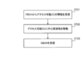
- the radio base station apparatus generates a PBCH signal including information on the initial downlink CC (bandwidth, number of antennas, CC that can receive DBCH (accessible CC), etc.) in the PBCH signal generation unit 2012, and transmits this PBCH signal. Therefore, the mobile terminal apparatus receives the PBCH signal (ST21).
- downlink CC (DCC) # 2 is an accessible CC.
- the mobile terminal apparatus moves the center frequency to the accessible CC based on the CC information broadcast on the PBCH (ST22).
- the mobile terminal apparatus receives the DBCH signal of the accessible CC (ST23), and uses the uplink CC information (bandwidth and center frequency) paired with the initial downlink CC to use the uplink transmission signal bandwidth limiter.
- the bandwidth of the upstream transmission signal is limited, and the upstream transmission center frequency control unit 115 controls the upstream transmission center frequency.
- a pair band of the accessible downlink CC (DCC # 2) and the uplink CC (UCC # 1) is determined (LTE pair band).
- the initial pair band search is completed.
- a pair band can be determined even when DBCH is not transmitted in all downlink CCs.
- a pair band can be quickly determined.
- the SCH signal reception unit 204 performs cell search using the SCH signal included in any one of the plurality of downlink CCs.
- the CC to be connected by cell search is defined as the initial downlink CC.
- downlink CC (DCC) # 4 is an initial downlink CC.
- the radio base station apparatus Since the radio base station apparatus generates a PBCH signal including initial downlink CC information (bandwidth, number of antennas, etc.) by the PBCH signal generation unit 2012 and transmits this PBCH signal, the mobile terminal apparatus transmits the PBCH signal. A signal is received (ST31). Next, the mobile terminal apparatus receives the DBCH signal. In this method, since information on accessible CC is included in the DBCH signal, the mobile terminal apparatus can recognize the accessible CC by receiving the DBCH signal (ST32). Here, in FIG. 8, downlink CC (DCC) # 2 is an accessible CC. Next, the mobile terminal apparatus moves the center frequency to the accessible CC based on the accessible CC information broadcast on the DBCH (ST33).
- DCC downlink CC
- the uplink transmission signal bandwidth limiting unit 114 limits the bandwidth of the uplink transmission signal, and the uplink transmission center frequency control unit 115 controls the upstream transmission center frequency. Accordingly, a pair band of the accessible downlink CC (DCC # 2) and the uplink CC (UCC # 1) is determined (LTE pair band). Thus, the initial pair band search is completed. Thereby, a pair band can be determined even when DBCH is not transmitted in all downlink CCs. According to such a cell search, since the information of accessible CC is not included in the PBCH signal, it is possible to prevent the overhead of the PBCH signal from increasing.
- the radio base station apparatus generates a broadcast information signal (DBCH signal) including a RACH parameter that can be identified by the DBCH signal generation unit 1013 as to whether the terminal is an LTE-A terminal, and transmits this DBCH signal.
- DBCH signal broadcast information signal
- the mobile terminal apparatus receives the DBCH signal.
- the mobile terminal apparatus generates a RACH signal based on the received RACH parameter in RACH signal generation section 212, and transmits the RACH signal to the radio base station apparatus using uplink CC (UCC # 1) (ST13). ).
- UCC # 1 uplink CC
- the radio base station apparatus When the radio base station apparatus receives the RACH signal in the uplink CC RACH signal reception unit (here, the UCH # 1 RACH signal reception unit) 110, the radio base station apparatus generates a RACH response signal and a MAC / RRC control signal generation unit 1014 generates a RACH response signal.
- the RACH response signal is transmitted to the mobile terminal apparatus by the initial downlink CC (DCC # 2).
- the mobile terminal apparatus After receiving the RACH response signal, the mobile terminal apparatus generates an uplink shared channel signal by the uplink shared channel signal generation unit 211, and transmits the uplink shared channel signal by the PUSCH (Physical Uplink Shared Channel) of the uplink CC (UCC # 1). Transmit to the radio base station apparatus.
- the uplink shared channel includes information on the transmission / reception bandwidth of the own device (UE capability information), and this UE capability information is notified to the radio base station device (ST13).
- the mobile terminal apparatus generates an uplink shared channel signal including UE capability information (information on transmission / reception bandwidth of the own apparatus) by the uplink shared channel signal generation unit 211, and the uplink shared channel signal is converted to an uplink CC (UCC #).
- the data is transmitted to the radio base station apparatus (ST13).
- the uplink shared channel signal receiving unit 109 receives the uplink shared channel signal
- UE capability information is sent to the pair band allocation control unit 111.
- the pair band allocation information control unit 111 allocates the upper and lower CC pair bands based on the UE capability (the bandwidth (40 MHz) for two CCs here).
- the pair band allocation control unit 111 sends the pair band allocation information to the shared channel scheduler 112.
- the shared channel scheduler 112 schedules the up / down control signal and the up / down shared channel signal using the pair band allocation information.
- the radio base station apparatus generates a control signal (MAC / RRC control signal) by the RACH response signal and MAC / RRC control signal generation unit 1014, and this downlink CC (DCC # 2) PDSCH (Physical Downlink Shared Channel)
- the control signal is transmitted to the mobile terminal device.
- the control signal (MAC / RRC control signal) includes pair band allocation information, and this pair band allocation information is notified to the mobile terminal apparatus (ST14). Thus far, the processing in the initial pair band is completed.
- the pair band allocation information is sent to the pair band allocation information storage unit 216 and stored therein.
- the This pair band allocation information is sent to the downlink reception signal bandwidth extraction unit 202, the downlink reception center frequency control unit 201, the uplink transmission signal bandwidth limiter 214, and the uplink transmission center frequency control unit 215, and is assigned by each processing unit.
- the frequency is adjusted (moved) based on the pair band (ST15).
- the downlink reception center frequency control unit 201 adjusts to the center frequency of the bandwidth (aggregated CCs) of the downlink CCs (DCC # 1, DCC # 2, DCC # 3), and the downlink reception signal band
- the width extraction unit 202 extracts a downlink reception signal with a bandwidth of downlink CCs (DCC # 1, DCC # 2, DCC # 3).
- the uplink transmission center frequency control unit 215 adjusts to the center frequency of the bandwidth (aggregated CCs) of the uplink CCs (UCC # 1, UCC # 2), and the uplink transmission signal bandwidth limiting unit 214
- the uplink transmission signal is limited to the bandwidth of CCs (UCC # 1, UCC # 2).
- the mobile terminal apparatus communicates with the radio base station apparatus using the allocated wide frequency band. Thereafter, the mobile terminal apparatus receives downlink control information (L1 / L2 control signal), collates the user ID, and decodes radio resource allocation information corresponding to the user ID (blind decoding) (ST16). Thereafter, the mobile terminal device transmits and receives the shared data channel.
- L1 / L2 control signal downlink control information
- the mobile terminal apparatus receives downlink control information (L1 / L2 control signal)
- collates the user ID collates the user ID
- decodes radio resource allocation information corresponding to the user ID blind decoding
- a pair band (DCC # 2-UCC # 1) is determined in the same manner as in the LTE system, and UE capability information and pairing are performed using the pair band.
- the band allocation information is transmitted and received to determine the pair bands (DCC # 1, DCC # 2, DCC # 3-UCC # 1, UCC # 2) allocated in a wide band. Therefore, when a plurality of mobile communication systems (LTE system and LTE-A system) coexist, initial access can be made corresponding to each mobile communication system.
- an LTE system compatible mobile terminal device cannot detect an SCH or PBCH unique to the LTE-A system (or cannot detect SCH or PBCH in a certain CC because it is not transmitted). A cell search is performed using only the SCH. Therefore, the mobile terminal apparatus compatible with the LTE system can be initially accessed with a desired CC.
- an LTE-A system-specific SCH (PBCH) is transmitted in a downlink CC and an LTE system SCH (PBCH) is transmitted in another downlink CC
- PBCH LTE system SCH
- a transmission method is employed in which the SCH (PBCH) is not transmitted in the CC, but the SCH (PBCH) for the LTE system is transmitted in another downlink CC.
- the SCH (PBCH) for the LTE system is multiplexed on the downlink CC to be initially accessed by the mobile terminal apparatus compatible with the LTE system.
- the mobile terminal apparatus supporting the LTE system cannot initially access the downlink CC in which the SCH (PBCH) unique to the LTE-A system is multiplexed or the downlink CC in which the SCH (PBCH) is not multiplexed.
- the initial access is made by the CC in which the LTE system SCH (PBCH) is multiplexed. Since the CC to be initially accessed is the CC to be initially accessed by the mobile terminal apparatus compatible with the LTE system, it is not necessary to move the frequency from the CC detected by the cell search to a different CC at the stage of starting communication.
- the control delay between the radio base station apparatus and the mobile terminal apparatus can be shortened. Furthermore, since it is not necessary to notify the mobile terminal device of control information for moving the CC (or the control information can be reduced if necessary), the amount of control information overhead can be reduced. it can. Furthermore, there is a possibility that the cell search time can be shortened as compared with the method of notifying the control information for moving the CC.
- the present invention is not limited to the above embodiment, and can be implemented with various modifications.
- the allocation of component carriers, the number of processing units, the processing procedure, the number of component carriers, and the number of sets of component carriers in the above description can be changed as appropriate. is there. Other modifications can be made without departing from the scope of the present invention.
Landscapes
- Engineering & Computer Science (AREA)
- Signal Processing (AREA)
- Computer Networks & Wireless Communication (AREA)
- Databases & Information Systems (AREA)
- Mobile Radio Communication Systems (AREA)
Abstract
Priority Applications (1)
| Application Number | Priority Date | Filing Date | Title |
|---|---|---|---|
| US13/126,725 US20110261771A1 (en) | 2008-11-04 | 2009-10-30 | Radio base station apparatus and mobile terminal apparatus |
Applications Claiming Priority (4)
| Application Number | Priority Date | Filing Date | Title |
|---|---|---|---|
| JP2008283756 | 2008-11-04 | ||
| JP2008-283756 | 2008-11-04 | ||
| JP2009179826A JP5291565B2 (ja) | 2008-11-04 | 2009-07-31 | 無線基地局装置及び移動端末装置 |
| JP2009-179826 | 2009-07-31 |
Publications (1)
| Publication Number | Publication Date |
|---|---|
| WO2010053054A1 true WO2010053054A1 (fr) | 2010-05-14 |
Family
ID=42152864
Family Applications (1)
| Application Number | Title | Priority Date | Filing Date |
|---|---|---|---|
| PCT/JP2009/068672 WO2010053054A1 (fr) | 2008-11-04 | 2009-10-30 | Dispositif de station de base sans fil et dispositif de terminal mobile |
Country Status (3)
| Country | Link |
|---|---|
| US (1) | US20110261771A1 (fr) |
| JP (1) | JP5291565B2 (fr) |
| WO (1) | WO2010053054A1 (fr) |
Cited By (5)
| Publication number | Priority date | Publication date | Assignee | Title |
|---|---|---|---|---|
| WO2011145151A1 (fr) * | 2010-05-21 | 2011-11-24 | 富士通株式会社 | Émetteur, récepteur, système de communication et procédé de communication |
| CN103583006A (zh) * | 2011-04-01 | 2014-02-12 | 英特尔公司 | 用于配置扩展载波的增强型节点b和方法 |
| WO2014129040A1 (fr) * | 2013-02-22 | 2014-08-28 | ソニー株式会社 | Dispositif de commande de communication, procédé de commande de communication et dispositif terminal |
| CN109863711A (zh) * | 2016-09-26 | 2019-06-07 | 高通股份有限公司 | 用于有助于单载波内的多个同步信道的设备和方法 |
| WO2020252794A1 (fr) * | 2019-06-21 | 2020-12-24 | 小米通讯技术有限公司 | Procédé et dispositif de traitement de paramètres de capacité, dispositif de communication et support d'enregistrement |
Families Citing this family (7)
| Publication number | Priority date | Publication date | Assignee | Title |
|---|---|---|---|---|
| CN102378370B (zh) * | 2010-08-13 | 2014-10-29 | 电信科学技术研究院 | 一种载波聚合能力的处理方法和设备 |
| US8817728B2 (en) * | 2011-02-22 | 2014-08-26 | Qualcomm Incorporated | System and method for third-party assisted peer-to-peer communication |
| JP5954908B2 (ja) * | 2014-09-22 | 2016-07-20 | シャープ株式会社 | 移動局装置、通信制御方法、及び基地局装置 |
| JP6757323B2 (ja) * | 2015-09-01 | 2020-09-16 | 株式会社Nttドコモ | 端末及び無線通信方法 |
| CN107124767B (zh) * | 2016-02-25 | 2021-11-23 | 中兴通讯股份有限公司 | 一种信号配置方法、信息处理方法及装置 |
| BR112018069233A2 (pt) | 2016-03-31 | 2019-01-22 | Sony Corp | estação base, dispositivo de terminal, e, método de comunicação. |
| EP4142333A4 (fr) * | 2020-04-21 | 2024-01-10 | Ntt Docomo, Inc. | Terminal et procédé de communication |
Citations (2)
| Publication number | Priority date | Publication date | Assignee | Title |
|---|---|---|---|---|
| JPH05206942A (ja) * | 1992-01-27 | 1993-08-13 | Nippon Telegr & Teleph Corp <Ntt> | 空きチャネル検出方式 |
| JP2007129706A (ja) * | 2005-11-02 | 2007-05-24 | Agilent Technol Inc | Umtsセルのトラフィックを追跡するシステム及び方法 |
Family Cites Families (8)
| Publication number | Priority date | Publication date | Assignee | Title |
|---|---|---|---|---|
| US8335196B2 (en) * | 2006-09-19 | 2012-12-18 | Qualcomm Incorporated | Accommodating wideband and narrowband communication devices |
| WO2009020017A1 (fr) * | 2007-08-07 | 2009-02-12 | Sharp Kabushiki Kaisha | Dispositif de station de base, dispositif de station mobile, système de communication et procédé de communication |
| US8625568B2 (en) * | 2007-09-21 | 2014-01-07 | Lg Electronics Inc. | Method of mapping physical resource to logical resource in wireless communication system |
| US8340014B2 (en) * | 2007-12-26 | 2012-12-25 | Lg Electronics Inc. | Method for transmitting and receiving signals using multi-band radio frequencies |
| JP5386506B2 (ja) * | 2008-01-02 | 2014-01-15 | インターデイジタル パテント ホールディングス インコーポレイテッド | Lteにおけるcqi報告のための構成 |
| US8711811B2 (en) * | 2008-06-19 | 2014-04-29 | Telefonaktiebolaget L M Ericsson (Publ) | Identifying multi-component carrier cells |
| US9203595B2 (en) * | 2008-10-22 | 2015-12-01 | Lg Electronics Inc. | Efficient initial access system under a multi-carrier combination condition for supporting broadband |
| US8077670B2 (en) * | 2009-04-10 | 2011-12-13 | Jianke Fan | Random access channel response handling with aggregated component carriers |
-
2009
- 2009-07-31 JP JP2009179826A patent/JP5291565B2/ja active Active
- 2009-10-30 US US13/126,725 patent/US20110261771A1/en not_active Abandoned
- 2009-10-30 WO PCT/JP2009/068672 patent/WO2010053054A1/fr active Application Filing
Patent Citations (2)
| Publication number | Priority date | Publication date | Assignee | Title |
|---|---|---|---|---|
| JPH05206942A (ja) * | 1992-01-27 | 1993-08-13 | Nippon Telegr & Teleph Corp <Ntt> | 空きチャネル検出方式 |
| JP2007129706A (ja) * | 2005-11-02 | 2007-05-24 | Agilent Technol Inc | Umtsセルのトラフィックを追跡するシステム及び方法 |
Non-Patent Citations (1)
| Title |
|---|
| PANASONIC: "Support of UL/DL asymmetric carrier aggregation", 3GPP TSG RAN WG1 #54, R1-082999, 22 August 2008 (2008-08-22) * |
Cited By (11)
| Publication number | Priority date | Publication date | Assignee | Title |
|---|---|---|---|---|
| WO2011145151A1 (fr) * | 2010-05-21 | 2011-11-24 | 富士通株式会社 | Émetteur, récepteur, système de communication et procédé de communication |
| JPWO2011145151A1 (ja) * | 2010-05-21 | 2013-07-22 | 富士通株式会社 | 送信機、受信機、通信システム、通信方法 |
| JP5445677B2 (ja) * | 2010-05-21 | 2014-03-19 | 富士通株式会社 | 送信機、受信機、通信システム、通信方法 |
| US8982822B2 (en) | 2010-05-21 | 2015-03-17 | Fujitsu Limited | Transmitter, receiver, communication system, and communication method |
| CN103583006A (zh) * | 2011-04-01 | 2014-02-12 | 英特尔公司 | 用于配置扩展载波的增强型节点b和方法 |
| WO2014129040A1 (fr) * | 2013-02-22 | 2014-08-28 | ソニー株式会社 | Dispositif de commande de communication, procédé de commande de communication et dispositif terminal |
| JPWO2014129040A1 (ja) * | 2013-02-22 | 2017-02-02 | ソニー株式会社 | 通信制御装置、通信制御方法及び端末装置 |
| US9924479B2 (en) | 2013-02-22 | 2018-03-20 | Sony Corporation | Communication control device, communication control method, and terminal device |
| CN109863711A (zh) * | 2016-09-26 | 2019-06-07 | 高通股份有限公司 | 用于有助于单载波内的多个同步信道的设备和方法 |
| WO2020252794A1 (fr) * | 2019-06-21 | 2020-12-24 | 小米通讯技术有限公司 | Procédé et dispositif de traitement de paramètres de capacité, dispositif de communication et support d'enregistrement |
| US12225515B2 (en) | 2019-06-21 | 2025-02-11 | Xiaomi Communications Co., Ltd. | Capability parameter processing method and device, communication device and storage medium |
Also Published As
| Publication number | Publication date |
|---|---|
| JP5291565B2 (ja) | 2013-09-18 |
| JP2010136326A (ja) | 2010-06-17 |
| US20110261771A1 (en) | 2011-10-27 |
Similar Documents
| Publication | Publication Date | Title |
|---|---|---|
| JP5291565B2 (ja) | 無線基地局装置及び移動端末装置 | |
| JP5145294B2 (ja) | 移動端末装置、無線基地局装置及び移動通信システム | |
| US11197271B2 (en) | Uplink multi-TTI scheduling in TDD system | |
| EP3179793B1 (fr) | Procédé et dispositif pour déterminer une ressource de données d2d pour une communication d2d | |
| JP5266311B2 (ja) | 移動局、基地局、基本周波数ブロック指定方法及び帯域制御方法 | |
| CN108462997B (zh) | 无线通信终端、基站装置、无线通信方法以及集成电路 | |
| US20210368563A1 (en) | Apparatus and method for transmitting d2d data based on resource pattern | |
| CN108259152B (zh) | 一种窄带通信中的调度方法和装置 | |
| CN102932880A (zh) | 多载波通信系统中的小区选择方法及装置 | |
| EP2966788B1 (fr) | Méthode de communication, station de base, équipement utilisateur et système | |
| JP5667662B2 (ja) | 無線基地局装置、移動端末装置及び無線通信方法 | |
| CN109561501B (zh) | 双工数据传输方法及基站和终端 | |
| JP5388389B2 (ja) | 移動端末装置及び無線基地局装置 | |
| KR20230100598A (ko) | 조건부 핸드오버를 수행하는 방법 및 장치 | |
| KR20230098549A (ko) | Ran 슬라이싱 관련 정보를 전송하는 장치 및 방법 | |
| JP2010087978A (ja) | 通信制御装置、通信システムおよび通信方法 |
Legal Events
| Date | Code | Title | Description |
|---|---|---|---|
| 121 | Ep: the epo has been informed by wipo that ep was designated in this application |
Ref document number: 09824754 Country of ref document: EP Kind code of ref document: A1 |
|
| WWE | Wipo information: entry into national phase |
Ref document number: 1814/KOLNP/2011 Country of ref document: IN |
|
| NENP | Non-entry into the national phase |
Ref country code: DE |
|
| WWE | Wipo information: entry into national phase |
Ref document number: 13126725 Country of ref document: US |
|
| 122 | Ep: pct application non-entry in european phase |
Ref document number: 09824754 Country of ref document: EP Kind code of ref document: A1 |