WO2005000576A1 - Flexible metal foil-polyimide laminate - Google Patents
Flexible metal foil-polyimide laminate Download PDFInfo
- Publication number
- WO2005000576A1 WO2005000576A1 PCT/JP2004/008773 JP2004008773W WO2005000576A1 WO 2005000576 A1 WO2005000576 A1 WO 2005000576A1 JP 2004008773 W JP2004008773 W JP 2004008773W WO 2005000576 A1 WO2005000576 A1 WO 2005000576A1
- Authority
- WO
- WIPO (PCT)
- Prior art keywords
- polyimide
- metal foil
- bis
- aminophenoxy
- dianhydride
- Prior art date
- Legal status (The legal status is an assumption and is not a legal conclusion. Google has not performed a legal analysis and makes no representation as to the accuracy of the status listed.)
- Ceased
Links
Classifications
-
- B—PERFORMING OPERATIONS; TRANSPORTING
- B32—LAYERED PRODUCTS
- B32B—LAYERED PRODUCTS, i.e. PRODUCTS BUILT-UP OF STRATA OF FLAT OR NON-FLAT, e.g. CELLULAR OR HONEYCOMB, FORM
- B32B27/00—Layered products comprising a layer of synthetic resin
- B32B27/28—Layered products comprising a layer of synthetic resin comprising synthetic resins not wholly covered by any one of the sub-groups B32B27/30 - B32B27/42
- B32B27/281—Layered products comprising a layer of synthetic resin comprising synthetic resins not wholly covered by any one of the sub-groups B32B27/30 - B32B27/42 comprising polyimides
-
- B—PERFORMING OPERATIONS; TRANSPORTING
- B32—LAYERED PRODUCTS
- B32B—LAYERED PRODUCTS, i.e. PRODUCTS BUILT-UP OF STRATA OF FLAT OR NON-FLAT, e.g. CELLULAR OR HONEYCOMB, FORM
- B32B15/00—Layered products comprising a layer of metal
- B32B15/04—Layered products comprising a layer of metal comprising metal as the main or only constituent of a layer, which is next to another layer of the same or of a different material
- B32B15/08—Layered products comprising a layer of metal comprising metal as the main or only constituent of a layer, which is next to another layer of the same or of a different material of synthetic resin
-
- B—PERFORMING OPERATIONS; TRANSPORTING
- B32—LAYERED PRODUCTS
- B32B—LAYERED PRODUCTS, i.e. PRODUCTS BUILT-UP OF STRATA OF FLAT OR NON-FLAT, e.g. CELLULAR OR HONEYCOMB, FORM
- B32B15/00—Layered products comprising a layer of metal
- B32B15/20—Layered products comprising a layer of metal comprising aluminium or copper
-
- H—ELECTRICITY
- H05—ELECTRIC TECHNIQUES NOT OTHERWISE PROVIDED FOR
- H05K—PRINTED CIRCUITS; CASINGS OR CONSTRUCTIONAL DETAILS OF ELECTRIC APPARATUS; MANUFACTURE OF ASSEMBLAGES OF ELECTRICAL COMPONENTS
- H05K1/00—Printed circuits
- H05K1/02—Details
- H05K1/03—Use of materials for the substrate
- H05K1/0313—Organic insulating material
- H05K1/032—Organic insulating material consisting of one material
- H05K1/0346—Organic insulating material consisting of one material containing N
-
- B—PERFORMING OPERATIONS; TRANSPORTING
- B32—LAYERED PRODUCTS
- B32B—LAYERED PRODUCTS, i.e. PRODUCTS BUILT-UP OF STRATA OF FLAT OR NON-FLAT, e.g. CELLULAR OR HONEYCOMB, FORM
- B32B2250/00—Layers arrangement
- B32B2250/03—3 layers
-
- B—PERFORMING OPERATIONS; TRANSPORTING
- B32—LAYERED PRODUCTS
- B32B—LAYERED PRODUCTS, i.e. PRODUCTS BUILT-UP OF STRATA OF FLAT OR NON-FLAT, e.g. CELLULAR OR HONEYCOMB, FORM
- B32B2274/00—Thermoplastic elastomer material
-
- B—PERFORMING OPERATIONS; TRANSPORTING
- B32—LAYERED PRODUCTS
- B32B—LAYERED PRODUCTS, i.e. PRODUCTS BUILT-UP OF STRATA OF FLAT OR NON-FLAT, e.g. CELLULAR OR HONEYCOMB, FORM
- B32B2307/00—Properties of the layers or laminate
- B32B2307/30—Properties of the layers or laminate having particular thermal properties
- B32B2307/306—Resistant to heat
-
- B—PERFORMING OPERATIONS; TRANSPORTING
- B32—LAYERED PRODUCTS
- B32B—LAYERED PRODUCTS, i.e. PRODUCTS BUILT-UP OF STRATA OF FLAT OR NON-FLAT, e.g. CELLULAR OR HONEYCOMB, FORM
- B32B2307/00—Properties of the layers or laminate
- B32B2307/50—Properties of the layers or laminate having particular mechanical properties
- B32B2307/546—Flexural strength; Flexion stiffness
-
- B—PERFORMING OPERATIONS; TRANSPORTING
- B32—LAYERED PRODUCTS
- B32B—LAYERED PRODUCTS, i.e. PRODUCTS BUILT-UP OF STRATA OF FLAT OR NON-FLAT, e.g. CELLULAR OR HONEYCOMB, FORM
- B32B2307/00—Properties of the layers or laminate
- B32B2307/70—Other properties
- B32B2307/714—Inert, i.e. inert to chemical degradation, corrosion
-
- B—PERFORMING OPERATIONS; TRANSPORTING
- B32—LAYERED PRODUCTS
- B32B—LAYERED PRODUCTS, i.e. PRODUCTS BUILT-UP OF STRATA OF FLAT OR NON-FLAT, e.g. CELLULAR OR HONEYCOMB, FORM
- B32B2307/00—Properties of the layers or laminate
- B32B2307/70—Other properties
- B32B2307/732—Dimensional properties
- B32B2307/734—Dimensional stability
-
- B—PERFORMING OPERATIONS; TRANSPORTING
- B32—LAYERED PRODUCTS
- B32B—LAYERED PRODUCTS, i.e. PRODUCTS BUILT-UP OF STRATA OF FLAT OR NON-FLAT, e.g. CELLULAR OR HONEYCOMB, FORM
- B32B2457/00—Electrical equipment
-
- B—PERFORMING OPERATIONS; TRANSPORTING
- B32—LAYERED PRODUCTS
- B32B—LAYERED PRODUCTS, i.e. PRODUCTS BUILT-UP OF STRATA OF FLAT OR NON-FLAT, e.g. CELLULAR OR HONEYCOMB, FORM
- B32B2457/00—Electrical equipment
- B32B2457/08—PCBs, i.e. printed circuit boards
-
- H—ELECTRICITY
- H05—ELECTRIC TECHNIQUES NOT OTHERWISE PROVIDED FOR
- H05K—PRINTED CIRCUITS; CASINGS OR CONSTRUCTIONAL DETAILS OF ELECTRIC APPARATUS; MANUFACTURE OF ASSEMBLAGES OF ELECTRICAL COMPONENTS
- H05K1/00—Printed circuits
- H05K1/02—Details
- H05K1/03—Use of materials for the substrate
- H05K1/0313—Organic insulating material
- H05K1/0353—Organic insulating material consisting of two or more materials, e.g. two or more polymers, polymer + filler, + reinforcement
- H05K1/036—Multilayers with layers of different types
-
- H—ELECTRICITY
- H05—ELECTRIC TECHNIQUES NOT OTHERWISE PROVIDED FOR
- H05K—PRINTED CIRCUITS; CASINGS OR CONSTRUCTIONAL DETAILS OF ELECTRIC APPARATUS; MANUFACTURE OF ASSEMBLAGES OF ELECTRICAL COMPONENTS
- H05K2201/00—Indexing scheme relating to printed circuits covered by H05K1/00
- H05K2201/01—Dielectrics
- H05K2201/0137—Materials
- H05K2201/0154—Polyimide
-
- Y—GENERAL TAGGING OF NEW TECHNOLOGICAL DEVELOPMENTS; GENERAL TAGGING OF CROSS-SECTIONAL TECHNOLOGIES SPANNING OVER SEVERAL SECTIONS OF THE IPC; TECHNICAL SUBJECTS COVERED BY FORMER USPC CROSS-REFERENCE ART COLLECTIONS [XRACs] AND DIGESTS
- Y10—TECHNICAL SUBJECTS COVERED BY FORMER USPC
- Y10T—TECHNICAL SUBJECTS COVERED BY FORMER US CLASSIFICATION
- Y10T428/00—Stock material or miscellaneous articles
- Y10T428/31504—Composite [nonstructural laminate]
- Y10T428/31721—Of polyimide
Definitions
- the present invention relates to a flexible metal foil polyimide laminate that is becoming widespread in the field of electronic industry, and particularly to a flexible polyimide metal foil laminate excellent in dimensional stability and heat resistance.
- the flexible metal foil laminate is mainly used as a base for a flexible printed wiring board.
- Conventional flexible metal foil laminates are manufactured by bonding metal foil to a commercially available polyimide film using an adhesive such as epoxy resin, so that they have heat resistance, chemical resistance, and flame retardancy.
- the properties and electrical properties are governed by the properties of the adhesive used, and the excellent properties of the polyimide film were not fully exploited, and were not particularly satisfactory in terms of heat resistance.
- a polyimide resin or polyimide resin precursor (polyamic acid) varnish is directly cast on the metal foil to form a bond.
- Polyimide flexible metal foil laminates without layers have been developed.
- the glass transition point (T g) of the polyimide resin of the layer in contact with the metal foil is generally lower than that of the other layers in order to secure the adhesion to the metal foil.
- a modified polyimide resin for example, a silicone-modified polyimide or polyamide imide may be used.
- Such flexible metal foil laminates have greatly improved heat resistance, etc., as compared to conventional flexible metal foil laminates having an adhesive layer made of epoxy resin, but they fully utilize the excellent properties of polyimide films. It is hard to say that it is.
- the glass transition point of a polyimide resin involved in adhesion is 192 ° C. [Synthesis Example 1], and a commercially available polyimide film (E. It is much lower than the glass transition point of 430 ° C of Le DuPont, trade name: Kapton H).
- Japanese Patent Application Laid-Open No. 2002-326280 discloses that a laminate having a three-layer structure using a thermoplastic resin as an adhesive layer generally has a thermocompression bonding temperature of 200 ° C. It discloses the problems involved in having to do the above. Disclosure of the invention
- An object of the present invention is to provide a flexible metal foil polyimide laminate that fully utilizes the properties of a heat-resistant polyimide film having excellent heat resistance, chemical resistance, flame retardancy, electrical properties, and the like. Things.
- a polyimide resin layer is formed between a polyimide film and a metal foil, and in particular, a polyimide resin layer that provides a glass transition point or solvent insolubility equivalent to or higher than that of a polyimide film is provided.
- a polyimide resin layer that provides a glass transition point or solvent insolubility equivalent to or higher than that of a polyimide film is provided.
- the present invention provides a polyimide resin layer by applying a precursor solution of a polyimide resin to a polyimide film or a metal foil, bonding the two, and then removing the solvent from the precursor solution and imidization.
- a polyimide resin layer by applying a precursor solution of a polyimide resin to a polyimide film or a metal foil, bonding the two, and then removing the solvent from the precursor solution and imidization.
- any polyimide film conventionally used for this kind of laminate may be used, and is represented by the following general formula (I).
- a polyimide resin film represented by the following general formula ( ⁇ ) obtained from a diamine compound represented by the following formula and a tetracarboxylic dianhydride represented by the following general formula ( ⁇ ) can be used, and a commercially available product can be used. You may.
- a commercial product As a commercial product,
- Toray DuPont Product name: Kapton Etc. can be used.
- H 2 NR 1 -NU 2 (I) (wherein, is an aliphatic group, a cycloaliphatic group, a monocyclic aromatic group, a condensed polycyclic aromatic group, or an aromatic group directly or crosslinked. And a divalent group selected from the group consisting of non-fused cyclic aromatic groups.
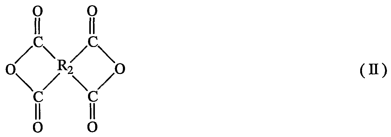
- R 2 is an aliphatic group, a cycloaliphatic group, a monocyclic aromatic group, a condensed polycyclic aromatic group, or a non-condensed cyclic aromatic group in which aromatic groups are connected directly or by a bridge member. Represents a tetravalent group selected from the group consisting of groups)
- Examples of the diamine compound represented by the general formula (I) include ⁇ -phenylenediamine, m-phenylenediamine, p-phenylenediamine, m-aminobenzylamine, p-aminobenzylamine, 2 —Chloro-1,2-phenylenediamine, 4-Chloro-1,2-phenylenediamine, 2,3-diaminotoluene, 2,4 diaminotoluene, 2,5-diaminotoluene, 2,6-diaminotoluene, 3, 4-Diaminotoluene, 2-Methoxy-1,4-phenylenediamine, 4-Methoxy-1,3-phenylenediamine, Benzidine, 3,3, Dichlorobenzidine, 3,3'-Dimethylbenzidine, 3 , 3 'dimethoxybenzidine, 3, 3' diaminodiphenyl ether, 3, 4 '-diaminodiphenyl ether,
- diamine compounds exemplified above it is preferable to use p-phenylenediamine and 4,4 ′ diaminodiphenyl ether.
- Examples of the tetracarboxylic dianhydride represented by the general formula ( ⁇ ) include, in the general formula ( ⁇ ), for example, ethylene tetracarboxylic dianhydride wherein R 2 is an aliphatic group, and R 2 is a ring.
- R 2 is a monocyclic aromatic group such as cyclopentanetetracarboxylic dianhydride such as a cyclopentanetetracarboxylic dianhydride, 1,2,3,4-benzenetetracarboxylic dianhydride, pyrometic dianhydride, R 2 is a condensed polycyclic aromatic group 2,3,6,7-naphthalenetetracarboxylic dianhydride, 1,4,5,8-naphthylenetetracarboxylic dianhydride, 1,2 , 5,6-naphthalenetetracarboxylic dianhydride, 3,4,9,10-perylenetetracarboxylic dianhydride, 2,3,6,7-anthracenetetracarboxylic dianhydride, 1,2 R 2 is a non-fused cyclic aromatic group in which aromatic groups are directly linked, such as 7,8-phenanthrenetetracarboxylic dianhydride 3,3 ', 4,4, -bi
- tetracarboxylic dianhydrides exemplified above, it is preferable to use pyromellitic dianhydride and 3,3 ′, 4,4, -biphenyltetracarboxylic dianhydride.
- the thickness of the polyimide film is appropriately selected and is not particularly limited, but is usually 10 to 50 m, particularly 12 to 25 / m.
- the type of metal foil used in the present invention is not particularly limited, and usually copper, nickel, aluminum, stainless steel, beryllium copper alloy, or the like is often used, and is used for forming a printed circuit. Copper foil is often used as the metal foil. As the copper foil, either a rolled copper foil or an electrolytic copper foil can be used. In addition, in order to increase the adhesion between the polyimide and the metal foil that is directly in contact with the metal foil, a simple metal or an oxide or an alloy thereof is formed on the metal foil.
- An inorganic layer such as copper, nickel-copper alloy or zinc-copper alloy may be formed, or a coupling agent such as aminosilane, epoxysilane, or mercaptosilane may be applied to the metal foil in addition to the inorganic material. Good.
- the thickness of the metal foil is also appropriately selected and is not particularly limited, but is usually from 3 to 50 m, particularly from 5 to 35 m.
- a polyimide resin layer is interposed between the polyimide film and the metal foil.
- the polyimide-based resin layer used in the present invention is applied on a polyimide film or a metal foil in a state of a polyimide-based resin precursor solution, and then the two are bonded together. It is preferably obtained by imidization.
- a polyimide resin in the state of a polyimide-based resin precursor solution, and then bond a metal foil to perform imidization.
- the polyimide-based resin layer of the present invention preferably has a glass transition point of 350 or more, more preferably has a glass transition temperature of 350 to 500 ° C, and particularly has a glass transition point of 350 to 450 ° C.
- An extremely heat-resistant laminate can be obtained.
- solvent resistance is represented by a peel strength measured when immersed in a solvent.
- Solvents include N-methylpyrrolidone (NMP), dimethylformamide (DMF), dimethylacetamide (DMAc), dimethylsulfoxide (DMSII), dimethyl sulfate, sulfolane, butyrolactone, cresol, phenol, halogenated Examples include phenol, cyclohexanone, dioxane, tetrahydrofuran, diglyme and the like.
- the polyimide-based resin layer a diamine similar to the formula (I) and the exemplified diamine described in the above-mentioned production of the polyimide film, and a tetracarboxylic dianhydride represented by the formula (II) and the exemplified tetracarboxylic dianhydride P-phenylenediamine and 4,4,1-diaminodiphenyl ether are preferred as the diamine compound, and pyromellitic dianhydride as the tetracarboxylic dianhydride, 3 , 3,4,4, -Biphenyltetracarboxylic dianhydride is preferred.
- the polyimide-based resin layer of the present invention can be selected from those that are not thermoplastic polyimides, and therefore, those that withstand solvents can be used. Therefore, the decrease in peel strength before and after immersion in the solvent is reduced to 50% or less, more preferably 30% or less,
- a flexible metal foil polyimide laminate having a solvent resistance reduction rate of 50% or less, more preferably 30% or less, and particularly 20% or less is obtained.
- thermoplastic polyimide referred to in the present invention generally has a glass transition point of less than 350 ° C., and is disclosed in Japanese Patent No. 3320516 and Japanese Patent Application Laid-Open No. 2002-326280. In other words, it is a structure disclosed in Japanese Patent Application Laid-open No. Hei 1-244841, Japanese Patent Application Laid-Open No. 2000-010310, Japanese Patent Application Laid-Open No. Hei 6-190967, etc. is there.
- the thickness of the polyimide resin layer is preferably 1 to 10 m, particularly preferably 2 to 5 m.
- the laminate of the present invention can intentionally combine the polyimide film and the polyimide resin layer, it is also possible to form a polyimide metal foil laminate emphasizing specific characteristics. For example, if a polyimide film that has been plasma-treated in advance is used, a polyimide metal foil laminate having excellent adhesion to the adhesive sheet can be obtained. (The polyimide film layer of the polyimide metal foil laminate can also be plasma-treated. However, a method using a polyimide film which has been plasma-treated in advance is industrially advantageous). This is extremely useful for the production of multilayer flexible printed circuits produced using adhesive sheets.
- a polyimide metal foil laminate excellent in flexibility and flexibility is desirable.
- flexibility is more advantageous as the elastic modulus of the entire resin layer is lower. Therefore, a polyimide metal foil laminate suitable for the purpose can be obtained by laminating a polyimide film having a medium to low elastic modulus by using a polyimide resin layer having a high elastic modulus and a glass transition point.
- a coupling agent may be added to the polyimide film or the polyimide-based resin layer according to the present invention to increase the adhesive force with the metal foil, or a surfactant may be added to increase the surface smoothness. Further, an additive for changing the other properties may be added. Further, in order to improve the adhesiveness of the polyimide film, a treatment such as a corona treatment, an etching treatment, and a plasma treatment may be performed in advance.
- the method for producing the polyimide film or polyimide resin according to the present invention is not particularly limited, and a conventionally known method can be applied.
- the three-necked flask with the stirrer and the dropping funnel was placed in an ice-water bath, and nitrogen gas was flown.
- 29.422 g of 3,3 ′, 4,4, -biphenyltetracarboxylic dianhydride and 200 g of dimethylacetamide (DMAc) were added, and the mixture was stirred for 30 minutes.
- DMAc dimethylacetamide
- a solution of 10.814 g of p-phenylenediamine dissolved in 100 g of DMAc was added from a dropping funnel over 15 minutes or more. This mixture was stirred at 10 to 15 ° C. for 2 hours and further at 25 ° C. for 6 hours to obtain a uniform polyimide resin precursor varnish composed of polyamic acid.
- a commercially available 9 m thick electrolytic copper foil (Furukawa Circuit Foil Co., Ltd., trade name: FI-WS) is coated with the polyimide resin precursor varnish of Synthesis Example 1 to a thickness of 50 m, and the blast drier After drying with a roll, a 50 m thick polyimide film (trade name: Upilex-S, manufactured by Ube Industries, Ltd.) was bonded at a temperature of 80 ° C using a roll press. Next, the residual solvent was removed with a blow dryer at 150 ° C, and the temperature was raised to 350 ° C in a nitrogen gas atmosphere to imidize the precursor, and the polyimide film, polyimide resin layer, and copper foil were used. A flexible copper foil laminate was obtained. The solder heat resistance, glass transition point, and solvent resistance of the obtained laminate were measured.
- thermoplastic polyimide [commercially available Upisel N (manufactured by Ube Industries, Ltd.)] is applied to a polyimide film and then bonded to a copper foil, and solder heat resistance, glass transition point, The solvent resistance was measured.
- the glass transition point of Upisel N was 242 ° C (catalog value), and the imidization ratio was 100%.
- the laminated plate test piece (length 25 mm ⁇ width 25 mm) was immersed in a solder bath at 350 ° C. for 30 seconds, visually observed for peeling or swelling, and evaluated according to the following criteria.
- the polyimide resin precursors of Synthesis Examples 1 and 2 were applied to a glass plate, dried at 50 for 30 minutes to remove the solvent, and then peeled off from the glass plate to obtain a 3 mm-thick polyimide precursor resin.
- a solution composition sheet sample was obtained. This sample was treated with 350 at 5 hours for imidization.
- the glass transition point of the product obtained by this imidization was measured using a thermal analyzer (manufactured by Rheometric Science, Inc .: analyzer name: RSA-III).
- Table 1 shows the above results.
- the present invention it is possible to easily provide a polyimide metal foil laminate that does not impair the excellent properties of the polyimide film in heat resistance and solvent resistance. Furthermore, since a polyimide film and a polyimide-based resin layer can be variously combined, it is possible to easily provide a characteristic flexible polyimide metal foil laminate.
Landscapes
- Engineering & Computer Science (AREA)
- Microelectronics & Electronic Packaging (AREA)
- Laminated Bodies (AREA)
Abstract
Description
明 細 書 Specification
フレキシブル金属箔ポリイミド積層板 技術分野 Flexible metal foil polyimide laminate Technical field
本発明は、 電子工業分野において普及しつつあるフレキシブル金属箔ポリイミ ド積層板に関するものであり、 特に寸法安定性や耐熱性に優れたフレキシブルポ リイミド金属箔積層板に関するものである。 背景技術 TECHNICAL FIELD The present invention relates to a flexible metal foil polyimide laminate that is becoming widespread in the field of electronic industry, and particularly to a flexible polyimide metal foil laminate excellent in dimensional stability and heat resistance. Background art
フレキシブル金属箔積層板は、 主として可撓性を有するプリント配線板用の基 材として使用される。 従来のフレキシブル金属箔積層板は、 エポキシ榭脂等の接 着剤を用いて、 市販のポリイミドフィルムに金属箔を貼り合わせることにより製 造されているために、 耐熱性 ·耐薬品性 ·難燃性 ·電気特性等は使用される接着 剤の特性に支配され、 ポリイミドフィルムの優れた諸特性が充分に生かされず、 特に耐熱性の点で充分なものではなかった。 この接着剤を有する従来のフレキシ ブル金属箔積層板の欠点を克服するために、 金属箔上にポリイミド樹脂又はポリ イミド樹脂前駆体 (ポリアミド酸) ワニスを直接流延'塗布することにより、 接 着層のないポリイミドフレキシブル金属箔積層板が開発されている。 The flexible metal foil laminate is mainly used as a base for a flexible printed wiring board. Conventional flexible metal foil laminates are manufactured by bonding metal foil to a commercially available polyimide film using an adhesive such as epoxy resin, so that they have heat resistance, chemical resistance, and flame retardancy. The properties and electrical properties are governed by the properties of the adhesive used, and the excellent properties of the polyimide film were not fully exploited, and were not particularly satisfactory in terms of heat resistance. In order to overcome the drawbacks of conventional flexible metal foil laminates with this adhesive, a polyimide resin or polyimide resin precursor (polyamic acid) varnish is directly cast on the metal foil to form a bond. Polyimide flexible metal foil laminates without layers have been developed.
例えば、 ポリイミド樹脂形成時の収縮に伴う反りを防止するため、 化学構造の 異なるポリイミド樹脂を多層積層する方法が報告されている。 この場合、 金属箔 との密着力を確保するために金属箔と接する層のポリイミド樹脂のガラス転移点 (T g ) は他の層のそれより低いのが一般的である。 また、 同様に反りを防止す るために、 変性したポリイミド樹脂、 例えばシリコーン変性のポリイミド榭皆や ポリアミドイミドなどを用いる場合もある。 For example, there has been reported a method of laminating multiple layers of polyimide resins having different chemical structures in order to prevent warpage due to shrinkage during formation of the polyimide resin. In this case, the glass transition point (T g) of the polyimide resin of the layer in contact with the metal foil is generally lower than that of the other layers in order to secure the adhesion to the metal foil. Similarly, in order to prevent warpage, a modified polyimide resin, for example, a silicone-modified polyimide or polyamide imide may be used.
このようなフレキシブル金属箔積層板は、 従来のエポキシ樹脂による接着層を 持つフレキシブル金属箔積層板に比較して耐熱性などにおいて大いに改善されて いるものの、 ポリイミドフィルムの優れた特性が充分に生かされているとはいい 難い。 例えば、 特許第 3 3 2 0 5 1 6号公報では、 接着に関わるポリイミド樹脂 のガラス転移点が 1 9 2 °C [合成例 1 ] であり、 市販のポリイミドフィルム (東 レ-デュポン社製、 商品名:カプトン H) のガラス転移点 4 3 0 °Cよりはるかに 低い。 Such flexible metal foil laminates have greatly improved heat resistance, etc., as compared to conventional flexible metal foil laminates having an adhesive layer made of epoxy resin, but they fully utilize the excellent properties of polyimide films. It is hard to say that it is. For example, in Japanese Patent No. 3320516, the glass transition point of a polyimide resin involved in adhesion is 192 ° C. [Synthesis Example 1], and a commercially available polyimide film (E. It is much lower than the glass transition point of 430 ° C of Le DuPont, trade name: Kapton H).
また、 特開 2 0 0 2— 3 2 6 2 8 0号公報には、 熱可塑性樹脂を接着層とする 3層構造の積層体の製造は加熱圧着の温度が一般的に 2 0 0 °C以上であることが 必要なことに伴う諸問題を開示している。 発明の開示 Also, Japanese Patent Application Laid-Open No. 2002-326280 discloses that a laminate having a three-layer structure using a thermoplastic resin as an adhesive layer generally has a thermocompression bonding temperature of 200 ° C. It discloses the problems involved in having to do the above. Disclosure of the invention
本発明は、 優れた耐熱性 ·耐薬品性 ·難燃性 ·電気的特性等を有する耐熱性ポ リイミドフィルムの特性を充分に生かしたフレキシブル金属箔ポリイミド積層板 を提供することを目的とするものである。 An object of the present invention is to provide a flexible metal foil polyimide laminate that fully utilizes the properties of a heat-resistant polyimide film having excellent heat resistance, chemical resistance, flame retardancy, electrical properties, and the like. Things.
本発明者らは、 鋭意研究の結果、 ポリイミドフィルムと金属箔の間にポリイミ ド系榭脂層を形成すること、 特にポリイミドフィルムと同等以上のガラス転移点 や溶剤不溶性を与えるポリイミド樹脂層を設けることで、 本発明の上記目的が達 成されることを知見し、 本発明をなすに至った。 As a result of intensive studies, the present inventors have found that a polyimide resin layer is formed between a polyimide film and a metal foil, and in particular, a polyimide resin layer that provides a glass transition point or solvent insolubility equivalent to or higher than that of a polyimide film is provided. Thus, the present inventors have found that the above objects of the present invention are achieved, and have accomplished the present invention.
即ち、 本発明は、 ポリイミドフィルムもしくは金属箔にポリイミド系榭脂の前 駆体溶液を塗布して、 両者を貼り合わせた後に、 前駆体溶液からの溶媒の除去、 イミド化などによりポリイミド系樹脂層を設けたポリイミドフィルム、 金属箔、 及びこれらポリイミドフィルムと金属箔の間に介在されたポリイミド系樹脂層の That is, the present invention provides a polyimide resin layer by applying a precursor solution of a polyimide resin to a polyimide film or a metal foil, bonding the two, and then removing the solvent from the precursor solution and imidization. Of polyimide film, metal foil, and polyimide resin layer interposed between these polyimide film and metal foil
3層からなるフレキシブル金属箔ポリイミド積層板を提供する。 発明を実施するための最良の形態 Provide a flexible metal foil polyimide laminate comprising three layers. BEST MODE FOR CARRYING OUT THE INVENTION
本発明のフレキシブル金属箔ポリイミド積層板の形成に用いるポリイミドフィ ルムとしては、 従来からこの種の積層板に使用されているいずれのポリイミドフ イルムを用いてもよく、 下記一般式 ( I ) で表されるジァミン化合物と下記一般 式 (Π) で表されるテトラカルボン酸二無水物とから得られる下記一般式 (Π) で表されるポリイミド樹脂のフィルムを用いることができ、 市販品を使用しても よい。 市販品としては、 As the polyimide film used for forming the flexible metal foil polyimide laminate of the present invention, any polyimide film conventionally used for this kind of laminate may be used, and is represented by the following general formula (I). A polyimide resin film represented by the following general formula (式) obtained from a diamine compound represented by the following formula and a tetracarboxylic dianhydride represented by the following general formula (式) can be used, and a commercially available product can be used. You may. As a commercial product,
鐘淵化学工業 (株) 製 商品名:ァピカル Manufactured by Kanegafuchi Chemical Industry Co., Ltd. Product name: Apical
東レ ·デュポン社製 商品名:カプトン 等が使用し得る。 Toray DuPont Product name: Kapton Etc. can be used.
H2N-R1-NU2 (I) (式中、 は脂肪族基、 環式脂肪族基、 単環式芳香族基、 縮合多環式芳香族基、 芳香族が直接又は架橋員により連結された非縮合環式芳香族基からなる群より選 ばれる 2価の基を示す。 ) H 2 NR 1 -NU 2 (I) (wherein, is an aliphatic group, a cycloaliphatic group, a monocyclic aromatic group, a condensed polycyclic aromatic group, or an aromatic group directly or crosslinked. And a divalent group selected from the group consisting of non-fused cyclic aromatic groups.
(式中、 R2は脂肪族基、 環式脂肪族基、 単環式芳香族基、 縮合多環式芳香族基、 芳香族基が直接又は架橋員により連結された非縮合環式芳香族基からなる群より 選ばれる 4価の基を示す。 ) (Wherein, R 2 is an aliphatic group, a cycloaliphatic group, a monocyclic aromatic group, a condensed polycyclic aromatic group, or a non-condensed cyclic aromatic group in which aromatic groups are connected directly or by a bridge member. Represents a tetravalent group selected from the group consisting of groups)

(式中、 Rp R2は上記の通り。 ) (In the formula, Rp R 2 is as described above.)
一般式 (I) で表されるジァミン化合物としては、 例えば Ο—フエ二レンジァ ミン、 m—フエ二レンジァミン、 p—フエ二レンジァミン、 m—ァミノべンジル ァミン、 p—ァミノベンジルァミン、 2—クロロー 1, 2—フエ二レンジァミン、 4一クロロー 1, 2—フエ二レンジァミン、 2, 3—ジァミノトルエン、 2, 4 ージァミノトルエン、 2, 5—ジァミノトルエン、 2, 6—ジァミノトルエン、 3, 4ージァミノトルエン、 2—メトキシー 1, 4—フエ二レンジァミン、 4— メトキシ一 1, 3—フエ二レンジァミン、 ベンジジン、 3, 3, ージクロ口ベン ジジン、 3, 3 ' ージメチルベンジジン、 3, 3 ' ージメトキシベンジジン、 3, 3 ' ージアミノジフエニルエーテル、 3, 4' —ジアミノジフエニルエーテル、 4, 4' —ジアミノジフエニルエーテル、 3, 3 ' —ジアミノジフエニルスルフ イド、 3, 4' —ジアミノジフエニルスルフイド、 4, 4' ージアミノジフエ二 ルスルフイド、 3, 3 ' ージアミノジフエニルスルホキシド、 4, 4' —ジアミ ノジフエニルスルホキシド、 3, 3 ' —ジアミノジフエニルスルホン、 3, 4' —ジアミノジフエニルスルホン、 4, 4' ージアミノジフエニルスルホン、 3, 3 ' ージァミノべンゾフエノン、 3, 4' —ジァミノべンゾフエノン、 4, 4' —ジァミノべンゾフエノン、 3, 3 ' —ジアミノジフエニルメタン、 3, 4, 一 ジアミノジフエニルメタン、 4, 4, —ジアミノジフエニルメタン、 ビス [4-Examples of the diamine compound represented by the general formula (I) include Ο-phenylenediamine, m-phenylenediamine, p-phenylenediamine, m-aminobenzylamine, p-aminobenzylamine, 2 —Chloro-1,2-phenylenediamine, 4-Chloro-1,2-phenylenediamine, 2,3-diaminotoluene, 2,4 diaminotoluene, 2,5-diaminotoluene, 2,6-diaminotoluene, 3, 4-Diaminotoluene, 2-Methoxy-1,4-phenylenediamine, 4-Methoxy-1,3-phenylenediamine, Benzidine, 3,3, Dichlorobenzidine, 3,3'-Dimethylbenzidine, 3 , 3 'dimethoxybenzidine, 3, 3' diaminodiphenyl ether, 3, 4 '-diaminodiphenyl ether, 4,4'-Diaminodiphenyl ether, 3,3'-Diaminodiphenyl sulfide, 3,4'-Diaminodiphenyl sulfide, 4,4'Diaminodiphenyl sulfide, 3,3'Diaminodiphenyl Sulfoxide, 4, 4'-diaminodidiphenylsulfoxide, 3,3'-diaminodiphenylsulfone, 3,4'-diaminodiphenylsulfone, 4,4 'diaminodiphenylsulfone, 3,3'diaminobenzophenone , 3, 4 '-diaminobenzophenone, 4, 4'-diaminobenzophenone, 3, 3 '-diaminodiphenylmethane, 3,4,1 diaminodiphenylmethane, 4,4,-diaminodiphenylmethane, bis [Four-
(3—アミノフエノキシ) フエニル] メタン、 ビス [4— (4—アミノフエノキ シ) フエニル] メタン、 1, 1一ビス [4一 (3—アミノフエノキシ) フエ二 ル] ェタン、 1, 1一ビス [4- (4一アミノフエノキシ) フエニル] ェタン、 1, 2—ビス [4— (3—アミノフエノキシ) フエニル] ェタン、 1, 2—ビス(3-Aminophenoxy) phenyl] methane, bis [4- (4-aminophenoxy) phenyl] methane, 1,1-bis [4-1 (3-aminophenoxy) phenyl] ethane, 1,1-bis [4- (4-Aminophenoxy) phenyl] ethane, 1,2-bis [4- (3-aminophenoxy) phenyl] ethane, 1,2-bis
[4— (4—アミノフエノキシ) フエニル] ェタン、 2, 2—ビス [4- (3- アミノフエノキシ) フエニル] プロパン、 2, 2—ビス [4一 (4—ァミノフエ ノキシ) フエニル] プロパン、 2, 2—ビス [4— (3—アミノフエノキシ) フ ェニル] ブタン、 2, 2—ビス [4- (4一アミノフエノキシ) フエニル] ブタ ン、 2, 2—ビス [4— (3—アミノフエノキシ) フエニル] — 1, 1, 1, 3, 3, 3—へキサフルォロプロパン、 2, 2—ビス [4一 (4—アミノフエノキ シ) フエニル] 一 1, 1, 1, 3, 3, 3—へキサフルォロプロパン、 1, 3— ビス (3—アミノフエノキシ) ベンゼン、 1, 3—ビス (4—アミノフエノキ シ) ベンゼン、 1, 4—ビス (3—アミノフエノキシ) ベンゼン、 1, 4一ビス[4- (4-aminophenoxy) phenyl] ethane, 2,2-bis [4- (3-aminophenoxy) phenyl] propane, 2,2-bis [4-1 (4-aminophenoxy) phenyl] propane, 2, 2 —Bis [4 -— (3-aminophenoxy) phenyl] butane, 2,2-bis [4- (4-aminophenyl) phenyl] butane, 2,2-bis [4- (3-aminophenyl) phenyl] — 1 , 1,1,3,3,3-hexafluoropropane, 2,2-bis [4- (4-aminophenoxy) phenyl] -1,1,1,1,3,3,3-hexafluro Oropropane, 1,3-bis (3-aminophenoxy) benzene, 1,3-bis (4-aminophenoxy) benzene, 1,4-bis (3-aminophenoxy) benzene, 1,4-bis
(4—アミノフエノキシ) ベンゼン、 4, 4, 一ビス (3—アミノフエノキシ) ビフエニル、 4, 4' —ビス (4—アミノフエノキシ) ピフエ二ル、 ビス [4一(4-aminophenoxy) benzene, 4,4,1-bis (3-aminophenoxy) biphenyl, 4,4'-bis (4-aminophenoxy) piphenyl, bis [4
(3—アミノフエノキシ) フエニル] ケトン、 ビス [4一 (4—ァミノフエノキ シ) フエニル] ケトン、 ビス [4— (3—アミノフエノキシ) フエニル] スルフ イド、 ビス [4一 (4—アミノフエノキシ) フエニル] スルフイド、 ビス [4— (3—アミノフエノキシ) フエニル] スルホキシド、 ビス [4— (4—アミノフ エノキシ) フエニル] スルホキシド、 ビス [4— (3—アミノフエノキシ) フエ ニル] スルホン、 ビス [4一 (4—アミノフエノキシ) フエニル] スルホン、 ビ ス [4— (3—アミノフエノキシ) フエニル] エーテル、 ビス [4一 (4一アミ ノフエノキシ) フエニル] エーテル、 1, 4—ビス [4一 (3—ァミノフエノキ シ) ベンゾィル] ベンゼン、 1, 3—ビス [4— (3—アミノフエノキシ) ベン ゾィル] ベンゼン、 4, 4一ビス [3— (4一アミノフエノキシ) ベンゾィル] ジフエニルエーテル、 4, 4—ビス [3— (3—アミノフエノキシ) ベンゾィ ル] ジフエニルエーテル、 4, 4一ビス [4一 (4—アミノー α, ひ—ジメチル ベンジル) フエノキシ] ベンゾフエノン、 4, 4一ビス [4一 (4—アミノー α, α—ジメチルペンジル) フエノキシ] ジフエニルスルホン、 ビス [4— [4- (4一アミノフエノキシ) フエノキシ] フエニル] ケトン、 ビス [4一 [4- (4—アミノフエノキシ) フエノキシ] フエニル] スルホン、 1, 4一ビス [4 ― (4—アミノフエノキシ) — a, CK—ジメチルペンジル] ベンゼン、 1, 3— ビス [4— (4一アミノフエノキシ) 一《, ひ一ジメチルペンジル] ベンゼン等 が挙げられ、 これらは単独であるいは 2種以上混合して使用される。 (3-aminophenoxy) phenyl] ketone, bis [4- (4-aminophenoxy) phenyl] ketone, bis [4- (3-aminophenoxy) phenyl] sulfide, bis [4- (4-aminophenyl) phenyl] sulfide, Bis [4- (3-aminophenoxy) phenyl] sulfoxide, bis [4- (4-aminophenoxy) phenyl] sulfoxide, bis [4- (3-aminophenoxy) phenyl] sulfone, bis [4- (4-aminophenoxy) Phenyl] sulfone, bi [4- (3-aminophenoxy) phenyl] ether, bis [4- (4-aminophenoxy) phenyl] ether, 1,4-bis [4-1 (3-aminophenoxy) benzoyl] benzene, 1,3-bis [4- (3-aminophenoxy) benzoyl] benzene, 4,4-bis [3- (4-aminophenoxy) benzoyl] diphenyl ether, 4,4-bis [3- (3-aminophenoxy) benzoyl] diphenyl Ether, 4,4-bis [4- (4-amino-α, hy-dimethylbenzyl) phenoxy] benzophenone, 4,4-bis [4- (4-amino-α, α-dimethylpentyl) phenoxy] diphenylsulfone , Bis [4 -— [4- (4-aminophenoxy) phenoxy] phenyl] ketone, bis [4- [4- (4-aminophenoxy) phenoxy] phenyl] sulfone, 1,4-bis [4 ― (4-aminophenoxy)-a, CK-dimethylpentyl] benzene, 1,3-bis [4- (4-aminophenoxy)-1, 1-dimethylpentyl] benzene, etc. Used as a mixture of more than one species.
また、 上記に例示されたジァミン化合物の中で、 p—フエ二レンジァミン、 4, 4' ージアミノジフエニルエーテルを使用することが好ましい。 Further, among the diamine compounds exemplified above, it is preferable to use p-phenylenediamine and 4,4 ′ diaminodiphenyl ether.
一般式 (Π) で表されるテトラカルボン酸二無水物としては、 一般式 (Π) に おいて、 例えば、 R2が脂肪族基であるエチレンテトラカルボン酸二無水物等、 R 2が環式脂肪族基であるシクロペンタンテトラカルボン酸ニ無水物等、 R 2が 単環式芳香族基である 1, 2, 3, 4—ベンゼンテトラカルボン酸二無水物、 ピ ロメット酸二無水物、 R2が縮合多環式芳香族基である 2, 3, 6, 7—ナフタ レンテトラカルボン酸二無水物、 1, 4, 5, 8—ナフ夕レンテトラカルボン酸 二無水物、 1, 2, 5, 6—ナフタレンテトラカルボン酸二無水物、 3, 4, 9, 1 0—ペリレンテトラカルボン酸二無水物、 2, 3, 6, 7—アントラセンテト ラカルボン酸二無水物、 1, 2, 7, 8—フエナントレンテトラカルボン酸二無 水物等、 R2が芳香族基を直接連結した非縮合環式芳香族基である 3, 3 ' , 4, 4, ービフエニルテトラカルボン酸二無水物、 2, 2, , 3, 3, ービフエニル テトラ力ルポン酸ニ無水物、 R 2が芳香族基を架橋員により連結した非縮合環式 芳香族基である 3, 3 ' , 4, 4' —ベンゾフエノンテ卜ラカルボン酸二無水物、 2, 2, , 3, 3, —ベンゾフエノンテトラカルボン酸二無水物、 2, 2—ビス ( 3 , 4ージカルボキシフエニル) プロパン二無水物、 2, 2—ビス (2, 3— ジカルボキシフエ二レ) プロパン二無水物、 ビス (3, 4ージカルボキシフエ二 ル) エーテル二無水物、 ビス (3, 4ージカルポキシフエニル) スルホン二無水 物、 ビス (2, 3—ジカルボキシフエニル) スルホン二無水物、 1 , 1一ビス ( 2 , 3—ジカルボキシフエニル) エタンニ無水物、 ビス (2, 3—ジカルポキ シフエニル) メタン二無水物、 ビス (3, 4ージカルポキシフエニル) メタン二 無水物、 4, 4, 一 (p—フエ二レンジォキシ) ジフタル酸二無水物、 4, 4 ' 一 (m—フエ二レンジォキシ) ジフタル酸二無水物等が挙げられ、 これらは単独 であるいは 2種以上混合して使用される。 Examples of the tetracarboxylic dianhydride represented by the general formula (Π) include, in the general formula (Π), for example, ethylene tetracarboxylic dianhydride wherein R 2 is an aliphatic group, and R 2 is a ring. R 2 is a monocyclic aromatic group such as cyclopentanetetracarboxylic dianhydride such as a cyclopentanetetracarboxylic dianhydride, 1,2,3,4-benzenetetracarboxylic dianhydride, pyrometic dianhydride, R 2 is a condensed polycyclic aromatic group 2,3,6,7-naphthalenetetracarboxylic dianhydride, 1,4,5,8-naphthylenetetracarboxylic dianhydride, 1,2 , 5,6-naphthalenetetracarboxylic dianhydride, 3,4,9,10-perylenetetracarboxylic dianhydride, 2,3,6,7-anthracenetetracarboxylic dianhydride, 1,2 R 2 is a non-fused cyclic aromatic group in which aromatic groups are directly linked, such as 7,8-phenanthrenetetracarboxylic dianhydride 3,3 ', 4,4, -biphenyltetracarboxylic dianhydride, 2,2,3,3,3-biphenyltetracarboxylic dianhydride, R 2 is an aromatic group linked by a crosslinking member 3,3 ', 4,4'-Benzophenonetetracarboxylic dianhydride, 2,2,, 3,3, -Benzophenonetetracarboxylic dianhydride, 2,2 which is a non-fused cyclic aromatic group -Screw (3,4-dicarboxyphenyl) propane dianhydride, 2,2-bis (2,3-dicarboxyphenyl) propane dianhydride, bis (3,4-dicarboxyphenyl) ether Anhydride, bis (3,4-dicarboxyphenyl) sulfone dianhydride, bis (2,3-dicarboxyphenyl) sulfone dianhydride, 1,1-bis (2,3-dicarboxyphenyl) Ethane dianhydride, bis (2,3-dicarboxyphenyl) methane dianhydride, bis (3,4 dicarboxyphenyl) methane dianhydride, 4,4,1- (p-phenylenedioxy) diphthalic dianhydride And 4,4 '-(m-phenylenedioxy) diphthalic dianhydride and the like, which may be used alone or as a mixture of two or more.
また、 上記に例示されたテトラカルボン酸二無水物の中で、 ピロメリット酸二 無水物、 3 , 3 ' , 4 , 4, ービフエニルテトラカルボン酸二無水物を使用する ことが好ましい。 Further, among the tetracarboxylic dianhydrides exemplified above, it is preferable to use pyromellitic dianhydride and 3,3 ′, 4,4, -biphenyltetracarboxylic dianhydride.
なお、 ポリイミドフィルムの厚さは適宜選定され、 特に限定されるものではな いが、 通常 1 0〜5 0 m、 特に 1 2〜2 5 / mである。 The thickness of the polyimide film is appropriately selected and is not particularly limited, but is usually 10 to 50 m, particularly 12 to 25 / m.
一方、 本発明に用いられる金属箔の種類には特に限定はなく、 通常は銅、 ニッ ケル、 アルミニウム、 ステンレス鋼、 ベリリウム銅合金等が使用されることが多 く、 印刷回路を形成するための金属箔としては銅箔が多く用いられる。 銅箔につ いては、 圧延銅箔、 電解銅箔のいずれも使用できる。 また、 金属箔に直接接して いるポリイミドと金属箔との接着力を高めるために、 金属箔上に金属単体やその 酸化物や合金、 例えば金属箔が銅箔の場合には、 銅単体、 酸化銅、 ニッケル一銅 合金や亜鉛—銅合金等の無機物層を形成させてもよく、 また、 無機物以外にもァ ミノシラン、 エポキシシラン、 メルカプトシラン等のカップリング剤を金属箔上 に塗布してもよい。 On the other hand, the type of metal foil used in the present invention is not particularly limited, and usually copper, nickel, aluminum, stainless steel, beryllium copper alloy, or the like is often used, and is used for forming a printed circuit. Copper foil is often used as the metal foil. As the copper foil, either a rolled copper foil or an electrolytic copper foil can be used. In addition, in order to increase the adhesion between the polyimide and the metal foil that is directly in contact with the metal foil, a simple metal or an oxide or an alloy thereof is formed on the metal foil. An inorganic layer such as copper, nickel-copper alloy or zinc-copper alloy may be formed, or a coupling agent such as aminosilane, epoxysilane, or mercaptosilane may be applied to the metal foil in addition to the inorganic material. Good.
金属箔の厚さも適宜選定され、 特に制限されるものではないが、 通常' 3〜5 0 m、 特に 5〜3 5 mである。 The thickness of the metal foil is also appropriately selected and is not particularly limited, but is usually from 3 to 50 m, particularly from 5 to 35 m.
本発明においては、 上記ポリイミドフィルムと金属箔との間にポリイミド系樹 脂層を介在させる。 In the present invention, a polyimide resin layer is interposed between the polyimide film and the metal foil.
本発明に用いられるポリイミド系樹脂層は、 ポリイミド系樹脂前駆体溶液の状 態にてポリイミドフィルムもしくは金属箔上に塗布した後、 両者を貼り合わせ、 イミド化することで得ることが好ましい。 The polyimide-based resin layer used in the present invention is applied on a polyimide film or a metal foil in a state of a polyimide-based resin precursor solution, and then the two are bonded together. It is preferably obtained by imidization.
特には、 ポリイミド系樹脂前駆体溶液の状態にてポリイミドフィルムに塗布し た後、 金属箔を貼り合わせて、 イミド化することが好ましい。 In particular, it is preferable to apply a polyimide resin in the state of a polyimide-based resin precursor solution, and then bond a metal foil to perform imidization.
また、 本発明のポリイミド系樹脂層は、 好ましくはガラス転移点が 350で以 上、 より好ましくは 350〜500°Cであるもの、 特には 350〜450°Cにあ るものを選択することで、 極めて耐熱性のある積層板を得ることができる。 Further, the polyimide-based resin layer of the present invention preferably has a glass transition point of 350 or more, more preferably has a glass transition temperature of 350 to 500 ° C, and particularly has a glass transition point of 350 to 450 ° C. An extremely heat-resistant laminate can be obtained.
更に、 本発明のポリイミド系樹脂層は、 耐溶剤性が熱可塑性ポリイミドよりも 高いものを選択することで、 極めて耐溶剤性のある積層板を得ることができる。 ここでいぅ耐溶剤性とは、 溶媒に浸漬して測定したときの剥離強度で表す。 溶 媒としては、 N—メチルピロリドン (NMP) 、 ジメチルホルムアミド (DM F) 、 ジメチルァセトアミド (DMAc) 、 ジメチルスルフオキサイド (DMS 〇) 、 硫酸ジメチル、 スルホラン、 プチロラクトン、 クレゾール、 フエノール、 ハロゲン化フエノール、 シクロへキサノン、 ジォキサン、 テトラヒドロフラン、 ダイグライム等が挙げられる。 Further, by selecting a polyimide resin layer of the present invention having higher solvent resistance than thermoplastic polyimide, a laminate having extremely solvent resistance can be obtained. Here, the solvent resistance is represented by a peel strength measured when immersed in a solvent. Solvents include N-methylpyrrolidone (NMP), dimethylformamide (DMF), dimethylacetamide (DMAc), dimethylsulfoxide (DMSII), dimethyl sulfate, sulfolane, butyrolactone, cresol, phenol, halogenated Examples include phenol, cyclohexanone, dioxane, tetrahydrofuran, diglyme and the like.
ここで、 ポリイミド系樹脂層としては、 上記したポリイミドフィルムの製造に おいて説明した式 (I) 及び例示したジァミンと同様のジァミンと、 式 (Π) 及 び例示したテ卜ラカルボン酸二無水物とから得られるものを使用することができ、 ジァミン化合物として P—フエ二レンジァミン、 4, 4, 一ジアミノジフエニル エーテルが好ましく、 またテトラカルボン酸二無水物としてピロメリット酸ニ無 水物、 3, 3, , 4, 4, —ビフエニルテトラカルボン酸二無水物が好ましい。 本発明のポリイミド系樹脂層は、 熱可塑性ポリイミドではないものを選択でき るので、 溶媒に耐えるものを使用することができる。 そのため、 溶媒に浸漬する 前後にて剥離強度の低下を 50%以下、 より好ましくは 30%以下、 特には 2 Here, as the polyimide-based resin layer, a diamine similar to the formula (I) and the exemplified diamine described in the above-mentioned production of the polyimide film, and a tetracarboxylic dianhydride represented by the formula (II) and the exemplified tetracarboxylic dianhydride P-phenylenediamine and 4,4,1-diaminodiphenyl ether are preferred as the diamine compound, and pyromellitic dianhydride as the tetracarboxylic dianhydride, 3 , 3,4,4, -Biphenyltetracarboxylic dianhydride is preferred. The polyimide-based resin layer of the present invention can be selected from those that are not thermoplastic polyimides, and therefore, those that withstand solvents can be used. Therefore, the decrease in peel strength before and after immersion in the solvent is reduced to 50% or less, more preferably 30% or less,
0%以下に抑えることができる。 It can be suppressed to 0% or less.
また、 本発明において、 耐溶剤性低下率が 50%以下、 より好ましくは 30% 以下、 特には 20%以下に抑えられたフレキシブル金属箔ポリイミド積層板が得 られる。 Further, in the present invention, a flexible metal foil polyimide laminate having a solvent resistance reduction rate of 50% or less, more preferably 30% or less, and particularly 20% or less is obtained.
本発明にいう熱可塑性ポリイミドとは、 一般にガラス転移点が 350°C未満で あり、 特許第 3320516号公報及び特開 2002-326280号公報、 も しくは特開平 1—2 4 4 8 4 1号公報、 特開 2 0 0 0— 1 0 3 0 1 0号公報、 特 開平 6— 1 9 0 9 6 7号公報等に示される構造物である。 The thermoplastic polyimide referred to in the present invention generally has a glass transition point of less than 350 ° C., and is disclosed in Japanese Patent No. 3320516 and Japanese Patent Application Laid-Open No. 2002-326280. In other words, it is a structure disclosed in Japanese Patent Application Laid-open No. Hei 1-244841, Japanese Patent Application Laid-Open No. 2000-010310, Japanese Patent Application Laid-Open No. Hei 6-190967, etc. is there.
なお、 上記耐溶剤性の測定方法、 条件は後述する通りである。 The method and conditions for measuring the solvent resistance are as described below.
上記ポリイミド系樹脂層の厚さは 1〜 1 0 m、 特に 2〜 5 mとすることが 好ましい。 The thickness of the polyimide resin layer is preferably 1 to 10 m, particularly preferably 2 to 5 m.
本発明の積層板は、 ポリイミドフィルムとポリイミド系榭脂層を意図的に組み 合せることが可能なので、 特定の特性を強調したポリイミド金属箔積層体を形成 することも可能である。 例えば、 予めプラズマ処理したポリイミドフィルムを用 いれば、 接着シートとの接着力に優れたポリイミド金属箔積層体が得られる (ポ リイミド金属箔積層体のポリイミドフィルム層をプラズマ処理することも可能で あるが、 予めプラズマ処理したポリイミドフィルムを用いる方法が工業的に有利 である) 。 このものは接着シートを使用して製造する多層フレキシブルプリント 回路の製造に極めて有益である。 Since the laminate of the present invention can intentionally combine the polyimide film and the polyimide resin layer, it is also possible to form a polyimide metal foil laminate emphasizing specific characteristics. For example, if a polyimide film that has been plasma-treated in advance is used, a polyimide metal foil laminate having excellent adhesion to the adhesive sheet can be obtained. (The polyimide film layer of the polyimide metal foil laminate can also be plasma-treated. However, a method using a polyimide film which has been plasma-treated in advance is industrially advantageous). This is extremely useful for the production of multilayer flexible printed circuits produced using adhesive sheets.
また、 例えば、 HD Dや光ピックアップ用途には、 屈曲性に優れ、 かつ柔軟性 に優れたポリイミド金属箔積層板が望ましい。 屈曲性は金属箔に接する接着層の 弾性率やガラス転移点が高いほど有利である。 一方、 柔軟性は全樹脂層の弾性率 が低いほど有利である。 従って、 高い弾性率とガラス転移点を与えるポリイミド 系樹脂層を用いて、 中—低弾性率のポリイミドフィルムを貼り合わせることによ り、 目的に合ったポリイミド金属箔積層体を得ることができる。 For example, for HDD and optical pickup applications, a polyimide metal foil laminate excellent in flexibility and flexibility is desirable. The higher the modulus of elasticity and the glass transition point of the adhesive layer in contact with the metal foil, the better the flexibility. On the other hand, flexibility is more advantageous as the elastic modulus of the entire resin layer is lower. Therefore, a polyimide metal foil laminate suitable for the purpose can be obtained by laminating a polyimide film having a medium to low elastic modulus by using a polyimide resin layer having a high elastic modulus and a glass transition point.
なお、 本発明にかかわるポリイミドフィルムやポリイミド系樹脂層には、 金属 箔との接着力を高くするためにカップリング剤を添加したり、 表面平滑性を高め るために界面活性剤を添加したり、 その他の特性を変化させるための添加剤ゃフ イラ一を添加してもよい。 また、 ポリイミドフィルムの接着性を向上させるため に、 予めコロナ処理、 エッチング処理、 プラズマ処理等の処理をしてもよい。 本発明にかかわるポリイミドフィルムやポリイミド系榭脂を製造する方法には 特に限定はなく、 従来公知の方法が適用できる。 In addition, a coupling agent may be added to the polyimide film or the polyimide-based resin layer according to the present invention to increase the adhesive force with the metal foil, or a surfactant may be added to increase the surface smoothness. Further, an additive for changing the other properties may be added. Further, in order to improve the adhesiveness of the polyimide film, a treatment such as a corona treatment, an etching treatment, and a plasma treatment may be performed in advance. The method for producing the polyimide film or polyimide resin according to the present invention is not particularly limited, and a conventionally known method can be applied.
以下、 合成例、 実施例及び比較例を示し、 本発明を具体的に説明するが、 本発 明は下記の実施例に制限されるものではない。 [合成例 1 ] Hereinafter, the present invention will be specifically described with reference to Synthesis Examples, Examples, and Comparative Examples, but the present invention is not limited to the following Examples. [Synthesis example 1]
撹拌機と滴下ロート付き三つ口フラスコを氷水浴中に据えて、 窒素ガスを流し た。 このフラスコに 3, 3' , 4, 4, ービフエニルテトラカルボン酸二無水物 29. 422 gとジメチルァセトアミド (DMAc) 200 gを加え、 30分間 撹拌した。 次いで、 p—フエ二レンジァミン 10. 814 gを DMAc 100 g に溶解した溶液を滴下ロートより 15分以上かけて加えた。 この混合物を 10〜 15°Cで 2時間、 更に 25 °Cで 6時間撹拌して、 ポリアミック酸からなる均一な ポリイミド樹脂前駆体ワニスを得た。 The three-necked flask with the stirrer and the dropping funnel was placed in an ice-water bath, and nitrogen gas was flown. To this flask, 29.422 g of 3,3 ′, 4,4, -biphenyltetracarboxylic dianhydride and 200 g of dimethylacetamide (DMAc) were added, and the mixture was stirred for 30 minutes. Next, a solution of 10.814 g of p-phenylenediamine dissolved in 100 g of DMAc was added from a dropping funnel over 15 minutes or more. This mixture was stirred at 10 to 15 ° C. for 2 hours and further at 25 ° C. for 6 hours to obtain a uniform polyimide resin precursor varnish composed of polyamic acid.
[合成例 2] [Synthesis example 2]
3, 3' , 4, 4' —ビフエニルテトラカルボン酸二無水物 29. 422 g、 4, 4' —ジアミノジフエニルエーテル 3. 003 g、 p—フエ二レンジァミン 9. 192 gを用い、 溶剤としてジメチルァセトアミド (DMAc) /N—メチ ルピロリドン (NMP) =2. 5X1 (質量比) 混合溶剤、 合計 300 gを用い る他は合成例 1と同様にてポリイミド樹脂前駆体ワニスを得た。 3,3 ', 4,4'-biphenyltetracarboxylic dianhydride 29.422 g, 4,4'-diaminodiphenyl ether 3.003 g, p-phenylenediamine 9.192 g, solvent Dimethylacetoamide (DMAc) / N-methylpyrrolidone (NMP) = 2.5X1 (mass ratio) Mixed solvent, 300 g total, except that a polyimide resin precursor varnish was obtained in the same manner as in Synthesis Example 1. Was.
[実施例 1 ] [Example 1]
市販の厚さ 9 mの電解銅箔 (古河サーキットホイル社製、 商品名: F I— W S) に合成例 1のポリイミド樹脂前駆体ワニスを厚さ 50 mになるように塗工 し、 送風乾燥機で乾燥した後に、 これと市販の厚さ 50 mのポリイミドフィル ム (宇部興産 (株) 製、 商品名:ユーピレックス— S) とをロールプレス機を用 い、 温度 80°Cで貼り合わせた。 次いで、 150°Cの送風乾燥機で残留溶媒を除 去し、 窒素ガス雰囲気下、 350°Cまで昇温して上記前駆体をイミド化して、 ポ リイミドフィルムとポリイミド樹脂層、 銅箔よりなるフレキシブル銅箔積層板を 得た。 得られた積層板の半田耐熱性、 ガラス転移点、 耐溶剤性を測定した。 A commercially available 9 m thick electrolytic copper foil (Furukawa Circuit Foil Co., Ltd., trade name: FI-WS) is coated with the polyimide resin precursor varnish of Synthesis Example 1 to a thickness of 50 m, and the blast drier After drying with a roll, a 50 m thick polyimide film (trade name: Upilex-S, manufactured by Ube Industries, Ltd.) was bonded at a temperature of 80 ° C using a roll press. Next, the residual solvent was removed with a blow dryer at 150 ° C, and the temperature was raised to 350 ° C in a nitrogen gas atmosphere to imidize the precursor, and the polyimide film, polyimide resin layer, and copper foil were used. A flexible copper foil laminate was obtained. The solder heat resistance, glass transition point, and solvent resistance of the obtained laminate were measured.
[実施例 2 ] [Example 2]
市販の厚さ 18 mの圧延銅箔 (ジャパンエナジー社製、 商品名: BHY) に 合成例 2のポリイミド樹脂前駆体ワニスを厚さ 50 tim塗工し、 実施例 1と同様 に送風乾燥機で乾燥した後、 実施例 1と同様な方法で市販の厚さ 25 mのポリ イミドフィルム (鐘淵化学工業 (株) 製、 商品名:アビカル NP I) を貼り合わ せ、 次いで、 実施例 1と同様にしてフレキシブルポリイミド銅箔積層板を得た。 得られた積層板の半田耐熱性、 ガラス転移点、 耐溶剤性を測定した。 Commercially available 18 m thick rolled copper foil (manufactured by Japan Energy Co., Ltd., trade name: BHY) was coated with the polyimide resin precursor varnish of Synthesis Example 2 to a thickness of 50 tim, and was air-dried in the same manner as in Example 1. After drying, a commercially available 25 m thick polyimide film (manufactured by Kaneka Chemical Industry Co., Ltd., trade name: Avical NPI) was laminated in the same manner as in Example 1, and then laminated with Example 1. Similarly, a flexible polyimide copper foil laminate was obtained. The solder heat resistance, glass transition point, and solvent resistance of the obtained laminate were measured.
[比較例 1 ] [Comparative Example 1]
熱可塑性ポリイミド [市販されているュピセル N (宇部興産 (株) 製) ] をポ リイミドフィルムに塗布してから銅箔と貼り合わせ、 実施例 1と同様にして半田 耐熱性、 ガラス転移点、 耐溶剤性を測定した。 A thermoplastic polyimide [commercially available Upisel N (manufactured by Ube Industries, Ltd.)] is applied to a polyimide film and then bonded to a copper foil, and solder heat resistance, glass transition point, The solvent resistance was measured.
なお、 ュピセル Nのガラス転移点は、 2 4 2 °C (カタログ値) であり、 イミド 化率は、 1 0 0 %であった。 The glass transition point of Upisel N was 242 ° C (catalog value), and the imidization ratio was 100%.
半田耐熱性の測定 Measurement of solder heat resistance
積層板試験片 (長さ 2 5 mmX幅 2 5 mm) を 3 5 0 °Cの半田浴に 3 0秒間浸 潰し、 剥がれや膨れの有無を目視で観察して、 下記の基準で評価した。 The laminated plate test piece (length 25 mm × width 25 mm) was immersed in a solder bath at 350 ° C. for 30 seconds, visually observed for peeling or swelling, and evaluated according to the following criteria.
〇:剥がれ、 膨れなし 〇: No peeling or swelling
X:剥がれ、 もしくは膨れあり X: Peeled or swollen
ガラス転移温度の測定 Measurement of glass transition temperature
合成例 1及び 2のポリイミド樹脂前駆体をガラス板に塗布し、 5 0 にて 3 0 分乾燥して溶媒を除去した後、 ガラス板より剥がして、 厚さ 3 mmの該ポリイミ ド前駆体樹脂溶液組成物シート試料を得た。 この試料を 3 5 0でにて 5時間処理 してイミド化した。 このイミド化して得られたものを熱分析計 (レオメトリック サイエンス社製、 :分析装置名: R S A— I I I ) を用いてガラス転移点を測定 した。 The polyimide resin precursors of Synthesis Examples 1 and 2 were applied to a glass plate, dried at 50 for 30 minutes to remove the solvent, and then peeled off from the glass plate to obtain a 3 mm-thick polyimide precursor resin. A solution composition sheet sample was obtained. This sample was treated with 350 at 5 hours for imidization. The glass transition point of the product obtained by this imidization was measured using a thermal analyzer (manufactured by Rheometric Science, Inc .: analyzer name: RSA-III).
耐溶剤性 Solvent resistance
J I S C 6 4 7 1に準拠して、 1 mm巾の回路を作製し、 引張り速度 5 0 m m 分、 引き剥がし角度 9 0 ° で剥離強度をジメチルァセトアミドに室温 (2 5 °C) で 5時間浸漬する前後で測定した。 Prepare a 1 mm wide circuit in accordance with JISC 6471 and apply a peeling strength of 90 mm at a pulling speed of 50 mm for dimethylacetoamide at room temperature (25 ° C). It was measured before and after immersion for hours.
以上の結果を表 1に示す。 表 1 Table 1 shows the above results. table 1

本発明によれば、 耐熱性ゃ耐溶剤性において、 ポリイミドフィルムの有する優 れた特性を全く損ねることのないポリイミド金属箔積層板を容易に供することが できる。 更にポリイミドフィルムとポリイミド系樹脂層を種々組み合わせること ができるので、 特徴のあるフレキシブルポリイミド金属箔積層板を容易に供する ことができる。 According to the present invention, it is possible to easily provide a polyimide metal foil laminate that does not impair the excellent properties of the polyimide film in heat resistance and solvent resistance. Furthermore, since a polyimide film and a polyimide-based resin layer can be variously combined, it is possible to easily provide a characteristic flexible polyimide metal foil laminate.
Claims
Priority Applications (2)
| Application Number | Priority Date | Filing Date | Title |
|---|---|---|---|
| CN2004800054650A CN1753782B (en) | 2003-06-25 | 2004-06-16 | Flexible Metal Foil-Polyimide Laminates |
| US10/544,346 US20060134443A1 (en) | 2003-06-25 | 2004-06-16 | Flexible metal foil-polyimide laminate |
Applications Claiming Priority (2)
| Application Number | Priority Date | Filing Date | Title |
|---|---|---|---|
| JP2003181341 | 2003-06-25 | ||
| JP2003-181341 | 2003-06-25 |
Publications (1)
| Publication Number | Publication Date |
|---|---|
| WO2005000576A1 true WO2005000576A1 (en) | 2005-01-06 |
Family
ID=33549524
Family Applications (1)
| Application Number | Title | Priority Date | Filing Date |
|---|---|---|---|
| PCT/JP2004/008773 Ceased WO2005000576A1 (en) | 2003-06-25 | 2004-06-16 | Flexible metal foil-polyimide laminate |
Country Status (5)
| Country | Link |
|---|---|
| US (1) | US20060134443A1 (en) |
| KR (1) | KR20060016742A (en) |
| CN (1) | CN1753782B (en) |
| TW (1) | TW200510172A (en) |
| WO (1) | WO2005000576A1 (en) |
Cited By (2)
| Publication number | Priority date | Publication date | Assignee | Title |
|---|---|---|---|---|
| KR100707056B1 (en) * | 2005-08-31 | 2007-04-13 | 씬플렉스 코포레이션 | Polyimide based flexible copper clad laminates and method of producing the same |
| WO2007097585A1 (en) * | 2006-02-24 | 2007-08-30 | Kolon Industries, Inc. | Double side conductor laminates and its manufacture |
Families Citing this family (4)
| Publication number | Priority date | Publication date | Assignee | Title |
|---|---|---|---|---|
| JP4200376B2 (en) * | 2004-02-17 | 2008-12-24 | 信越化学工業株式会社 | Flexible metal foil polyimide laminate and method for producing the same |
| KR100793177B1 (en) * | 2006-02-24 | 2008-01-10 | 주식회사 코오롱 | Flexible double-sided conductor laminate and its manufacturing method |
| TWI362398B (en) * | 2009-12-31 | 2012-04-21 | Ind Tech Res Inst | Polyimide polymers for flexible electrical device substrate material and flexible electrical devices comprising the same |
| CN102909934B (en) * | 2012-11-06 | 2016-02-17 | 江苏科技大学 | A kind of preparation method of flexible glue-free two-sided copper foil covered |
Citations (6)
| Publication number | Priority date | Publication date | Assignee | Title |
|---|---|---|---|---|
| JP2000043211A (en) * | 1998-07-31 | 2000-02-15 | Ube Ind Ltd | Polyimide film having improved adhesion, method for producing the same, and laminate |
| JP2000119607A (en) * | 1998-10-12 | 2000-04-25 | Kanegafuchi Chem Ind Co Ltd | Bonding sheet and method for manufacturing flexible copper-clad laminate using the same |
| JP2002144476A (en) * | 2000-08-28 | 2002-05-21 | Ube Ind Ltd | Polyimide film, substrate and processing method with good laser processability |
| JP2002240195A (en) * | 2001-02-19 | 2002-08-28 | Ube Ind Ltd | Polyimide copper clad board |
| JP2002316386A (en) * | 2001-04-20 | 2002-10-29 | Kanegafuchi Chem Ind Co Ltd | Copper clad laminate and method for producing the same |
| JP2002361792A (en) * | 2001-06-04 | 2002-12-18 | Mitsui Chemicals Inc | Laminated body of polyimide/metal foil |
Family Cites Families (6)
| Publication number | Priority date | Publication date | Assignee | Title |
|---|---|---|---|---|
| JP3347026B2 (en) * | 1997-07-23 | 2002-11-20 | 株式会社巴川製紙所 | Adhesive tape for electronic components |
| US6637649B2 (en) * | 1999-12-28 | 2003-10-28 | Christopher S. Walsh | Record and verification method, apparatus and system |
| TW574261B (en) * | 2000-08-28 | 2004-02-01 | Ube Industries | Method of producing through-hole in aromatic polyimide film |
| JP2005015596A (en) * | 2003-06-25 | 2005-01-20 | Shin Etsu Chem Co Ltd | Polyimide-based precursor resin solution composition sheet |
| JP2005167006A (en) * | 2003-12-03 | 2005-06-23 | Shin Etsu Chem Co Ltd | Method for producing flexible metal foil polyimide substrate |
| JP4200376B2 (en) * | 2004-02-17 | 2008-12-24 | 信越化学工業株式会社 | Flexible metal foil polyimide laminate and method for producing the same |
-
2004
- 2004-06-16 WO PCT/JP2004/008773 patent/WO2005000576A1/en not_active Ceased
- 2004-06-16 US US10/544,346 patent/US20060134443A1/en not_active Abandoned
- 2004-06-16 CN CN2004800054650A patent/CN1753782B/en not_active Expired - Fee Related
- 2004-06-16 KR KR1020057014191A patent/KR20060016742A/en not_active Ceased
- 2004-06-24 TW TW093118358A patent/TW200510172A/en unknown
Patent Citations (6)
| Publication number | Priority date | Publication date | Assignee | Title |
|---|---|---|---|---|
| JP2000043211A (en) * | 1998-07-31 | 2000-02-15 | Ube Ind Ltd | Polyimide film having improved adhesion, method for producing the same, and laminate |
| JP2000119607A (en) * | 1998-10-12 | 2000-04-25 | Kanegafuchi Chem Ind Co Ltd | Bonding sheet and method for manufacturing flexible copper-clad laminate using the same |
| JP2002144476A (en) * | 2000-08-28 | 2002-05-21 | Ube Ind Ltd | Polyimide film, substrate and processing method with good laser processability |
| JP2002240195A (en) * | 2001-02-19 | 2002-08-28 | Ube Ind Ltd | Polyimide copper clad board |
| JP2002316386A (en) * | 2001-04-20 | 2002-10-29 | Kanegafuchi Chem Ind Co Ltd | Copper clad laminate and method for producing the same |
| JP2002361792A (en) * | 2001-06-04 | 2002-12-18 | Mitsui Chemicals Inc | Laminated body of polyimide/metal foil |
Cited By (2)
| Publication number | Priority date | Publication date | Assignee | Title |
|---|---|---|---|---|
| KR100707056B1 (en) * | 2005-08-31 | 2007-04-13 | 씬플렉스 코포레이션 | Polyimide based flexible copper clad laminates and method of producing the same |
| WO2007097585A1 (en) * | 2006-02-24 | 2007-08-30 | Kolon Industries, Inc. | Double side conductor laminates and its manufacture |
Also Published As
| Publication number | Publication date |
|---|---|
| CN1753782B (en) | 2010-04-28 |
| CN1753782A (en) | 2006-03-29 |
| US20060134443A1 (en) | 2006-06-22 |
| TW200510172A (en) | 2005-03-16 |
| KR20060016742A (en) | 2006-02-22 |
Similar Documents
| Publication | Publication Date | Title |
|---|---|---|
| CN107312329B (en) | Polyimide film and copper-clad laminate | |
| TWI400268B (en) | Thermosetting resin composition and use thereof | |
| TW202012167A (en) | Metal-clad laminate and circuit board | |
| JPWO2008133182A1 (en) | Metal-resin laminate | |
| JP2006068920A (en) | Method for producing flexible copper foil polyimide laminate | |
| TW200819000A (en) | Laminate for wiring board | |
| JP2006224644A (en) | Insulating sheet, metallic layer and insulating sheet laminate, and printed wiring board using same | |
| JP2023006387A (en) | Polyamide acid, polyimide, polyimide film, metal-clad laminate and circuit board | |
| JP4205993B2 (en) | Metal laminate | |
| JP2004124091A (en) | Polyimide film, its production method and its use | |
| TWI683836B (en) | Polyimide laminated film, method for producing polyimide laminated film, method for producing thermoplastic polyimide, and method for producing flexible metal clad laminate | |
| JP3952196B2 (en) | Method for producing flexible metal foil polyimide laminate | |
| JP4174677B2 (en) | Flexible metal foil polyimide laminate and method for producing the same | |
| WO2005000576A1 (en) | Flexible metal foil-polyimide laminate | |
| JP2005035285A (en) | Flexible metal foil polyimide laminate | |
| KR100517233B1 (en) | Polyimide resin and polyimide-metal clad laminate | |
| JP2006015681A (en) | Flexible metal foil polyimide laminate and method for producing the same | |
| WO2007108137A1 (en) | Resin composition and metal laminate plate | |
| CN114672048A (en) | Polyimide film, metal-clad laminate, method for producing metal-clad laminate, and circuit board | |
| TW202237705A (en) | Polyimide, metal-clad laminate plate and circuit board | |
| JP4199654B2 (en) | Resin composition and metal laminate | |
| TWI869053B (en) | Polyimide resin composition, polyimide-based adhesive composition, polyimide adhesive film, and flexible metal clad laminate film | |
| JPH09227677A (en) | Polyimide siloxane composition for printing | |
| JP7621112B2 (en) | Metal-clad laminate and its manufacturing method | |
| JP2007254530A (en) | Laminated adhesive sheet, metal layer-adhered laminated adhesive sheet and circuit substrate |
Legal Events
| Date | Code | Title | Description |
|---|---|---|---|
| AK | Designated states |
Kind code of ref document: A1 Designated state(s): AE AG AL AM AT AU AZ BA BB BG BR BW BY BZ CA CH CN CO CR CU CZ DE DK DM DZ EC EE EG ES FI GB GD GE GH GM HR HU ID IL IN IS KE KG KP KR KZ LC LK LR LS LT LU LV MA MD MG MK MN MW MX MZ NA NI NO NZ OM PG PH PL PT RO RU SC SD SE SG SK SL SY TJ TM TN TR TT TZ UA UG US UZ VC VN YU ZA ZM ZW |
|
| AL | Designated countries for regional patents |
Kind code of ref document: A1 Designated state(s): GM KE LS MW MZ NA SD SL SZ TZ UG ZM ZW AM AZ BY KG KZ MD RU TJ TM AT BE BG CH CY CZ DE DK EE ES FI FR GB GR HU IE IT LU MC NL PL PT RO SE SI SK TR BF BJ CF CG CI CM GA GN GQ GW ML MR NE SN TD TG |
|
| 121 | Ep: the epo has been informed by wipo that ep was designated in this application | ||
| WWE | Wipo information: entry into national phase |
Ref document number: 1020057014191 Country of ref document: KR |
|
| ENP | Entry into the national phase |
Ref document number: 2006134443 Country of ref document: US Kind code of ref document: A1 |
|
| WWE | Wipo information: entry into national phase |
Ref document number: 10544346 Country of ref document: US |
|
| WWE | Wipo information: entry into national phase |
Ref document number: 20048054650 Country of ref document: CN |
|
| WWP | Wipo information: published in national office |
Ref document number: 1020057014191 Country of ref document: KR |
|
| WWP | Wipo information: published in national office |
Ref document number: 10544346 Country of ref document: US |
|
| 122 | Ep: pct application non-entry in european phase |