WO2002091487A1 - Light emitting apparatus - Google Patents
Light emitting apparatus Download PDFInfo
- Publication number
- WO2002091487A1 WO2002091487A1 PCT/JP2002/004349 JP0204349W WO02091487A1 WO 2002091487 A1 WO2002091487 A1 WO 2002091487A1 JP 0204349 W JP0204349 W JP 0204349W WO 02091487 A1 WO02091487 A1 WO 02091487A1
- Authority
- WO
- WIPO (PCT)
- Prior art keywords
- light emitting
- light
- complex
- emitting device
- hydrogen atom
- Prior art date
- Legal status (The legal status is an assumption and is not a legal conclusion. Google has not performed a legal analysis and makes no representation as to the accuracy of the status listed.)
- Ceased
Links
Classifications
-
- H—ELECTRICITY
- H10—SEMICONDUCTOR DEVICES; ELECTRIC SOLID-STATE DEVICES NOT OTHERWISE PROVIDED FOR
- H10H—INORGANIC LIGHT-EMITTING SEMICONDUCTOR DEVICES HAVING POTENTIAL BARRIERS
- H10H20/00—Individual inorganic light-emitting semiconductor devices having potential barriers, e.g. light-emitting diodes [LED]
- H10H20/80—Constructional details
- H10H20/85—Packages
- H10H20/851—Wavelength conversion means
- H10H20/8511—Wavelength conversion means characterised by their material, e.g. binder
- H10H20/8512—Wavelength conversion materials
-
- C—CHEMISTRY; METALLURGY
- C09—DYES; PAINTS; POLISHES; NATURAL RESINS; ADHESIVES; COMPOSITIONS NOT OTHERWISE PROVIDED FOR; APPLICATIONS OF MATERIALS NOT OTHERWISE PROVIDED FOR
- C09K—MATERIALS FOR MISCELLANEOUS APPLICATIONS, NOT PROVIDED FOR ELSEWHERE
- C09K11/00—Luminescent, e.g. electroluminescent, chemiluminescent materials
- C09K11/06—Luminescent, e.g. electroluminescent, chemiluminescent materials containing organic luminescent materials
-
- H—ELECTRICITY
- H05—ELECTRIC TECHNIQUES NOT OTHERWISE PROVIDED FOR
- H05B—ELECTRIC HEATING; ELECTRIC LIGHT SOURCES NOT OTHERWISE PROVIDED FOR; CIRCUIT ARRANGEMENTS FOR ELECTRIC LIGHT SOURCES, IN GENERAL
- H05B33/00—Electroluminescent light sources
- H05B33/12—Light sources with substantially two-dimensional radiating surfaces
- H05B33/14—Light sources with substantially two-dimensional radiating surfaces characterised by the chemical or physical composition or the arrangement of the electroluminescent material, or by the simultaneous addition of the electroluminescent material in or onto the light source
-
- C—CHEMISTRY; METALLURGY
- C09—DYES; PAINTS; POLISHES; NATURAL RESINS; ADHESIVES; COMPOSITIONS NOT OTHERWISE PROVIDED FOR; APPLICATIONS OF MATERIALS NOT OTHERWISE PROVIDED FOR
- C09K—MATERIALS FOR MISCELLANEOUS APPLICATIONS, NOT PROVIDED FOR ELSEWHERE
- C09K2211/00—Chemical nature of organic luminescent or tenebrescent compounds
- C09K2211/18—Metal complexes
- C09K2211/182—Metal complexes of the rare earth metals, i.e. Sc, Y or lanthanide
-
- H—ELECTRICITY
- H01—ELECTRIC ELEMENTS
- H01S—DEVICES USING THE PROCESS OF LIGHT AMPLIFICATION BY STIMULATED EMISSION OF RADIATION [LASER] TO AMPLIFY OR GENERATE LIGHT; DEVICES USING STIMULATED EMISSION OF ELECTROMAGNETIC RADIATION IN WAVE RANGES OTHER THAN OPTICAL
- H01S5/00—Semiconductor lasers
- H01S5/005—Optical components external to the laser cavity, specially adapted therefor, e.g. for homogenisation or merging of the beams or for manipulating laser pulses, e.g. pulse shaping
- H01S5/0087—Optical components external to the laser cavity, specially adapted therefor, e.g. for homogenisation or merging of the beams or for manipulating laser pulses, e.g. pulse shaping for illuminating phosphorescent or fluorescent materials, e.g. using optical arrangements specifically adapted for guiding or shaping laser beams illuminating these materials
-
- H—ELECTRICITY
- H01—ELECTRIC ELEMENTS
- H01S—DEVICES USING THE PROCESS OF LIGHT AMPLIFICATION BY STIMULATED EMISSION OF RADIATION [LASER] TO AMPLIFY OR GENERATE LIGHT; DEVICES USING STIMULATED EMISSION OF ELECTROMAGNETIC RADIATION IN WAVE RANGES OTHER THAN OPTICAL
- H01S5/00—Semiconductor lasers
- H01S5/02—Structural details or components not essential to laser action
- H01S5/022—Mountings; Housings
- H01S5/02218—Material of the housings; Filling of the housings
- H01S5/02234—Resin-filled housings; the housings being made of resin
-
- H—ELECTRICITY
- H01—ELECTRIC ELEMENTS
- H01S—DEVICES USING THE PROCESS OF LIGHT AMPLIFICATION BY STIMULATED EMISSION OF RADIATION [LASER] TO AMPLIFY OR GENERATE LIGHT; DEVICES USING STIMULATED EMISSION OF ELECTROMAGNETIC RADIATION IN WAVE RANGES OTHER THAN OPTICAL
- H01S5/00—Semiconductor lasers
- H01S5/30—Structure or shape of the active region; Materials used for the active region
- H01S5/32—Structure or shape of the active region; Materials used for the active region comprising PN junctions, e.g. hetero- or double- heterostructures
- H01S5/323—Structure or shape of the active region; Materials used for the active region comprising PN junctions, e.g. hetero- or double- heterostructures in AIIIBV compounds, e.g. AlGaAs-laser, InP-based laser
- H01S5/32308—Structure or shape of the active region; Materials used for the active region comprising PN junctions, e.g. hetero- or double- heterostructures in AIIIBV compounds, e.g. AlGaAs-laser, InP-based laser emitting light at a wavelength less than 900 nm
- H01S5/32341—Structure or shape of the active region; Materials used for the active region comprising PN junctions, e.g. hetero- or double- heterostructures in AIIIBV compounds, e.g. AlGaAs-laser, InP-based laser emitting light at a wavelength less than 900 nm blue laser based on GaN or GaP
-
- Y—GENERAL TAGGING OF NEW TECHNOLOGICAL DEVELOPMENTS; GENERAL TAGGING OF CROSS-SECTIONAL TECHNOLOGIES SPANNING OVER SEVERAL SECTIONS OF THE IPC; TECHNICAL SUBJECTS COVERED BY FORMER USPC CROSS-REFERENCE ART COLLECTIONS [XRACs] AND DIGESTS
- Y02—TECHNOLOGIES OR APPLICATIONS FOR MITIGATION OR ADAPTATION AGAINST CLIMATE CHANGE
- Y02B—CLIMATE CHANGE MITIGATION TECHNOLOGIES RELATED TO BUILDINGS, e.g. HOUSING, HOUSE APPLIANCES OR RELATED END-USER APPLICATIONS
- Y02B20/00—Energy efficient lighting technologies, e.g. halogen lamps or gas discharge lamps
Definitions
- the present invention relates to a light emitting device in which a wavelength conversion material containing an organic phosphor composed of a rare earth complex is combined with a light emitting diode or a semiconductor laser that excites the wavelength converting material.
- LEDs light emitting diodes
- they are highly monochromatic (ie, have a narrow spectral bandwidth at half maximum).
- full-color display devices in which red (R) green (G) blue (B) color LED emitters are mounted vertically and horizontally on a plane are already widely used.
- the display color is arbitrarily controlled by the intensity ratio of each RGB color.
- LEDs still have many problems when viewed as lighting devices rather than as display devices.
- white light can be obtained by using a device in which RGB LED light emitters are arranged and setting the intensity ratio of each RGB color appropriately, but when viewed as a lighting device, a conventional lighting device Compared with the incandescent lamps and fluorescent lamps, there are problems such as (1) the scale of the device is large, (2) the RGB colors must be controlled independently, and (3) the "color rendering properties" are poor.
- color rendering refers to the nature of the light source, such as what color the object looks like when the object is illuminated by the light source.
- CIE Commission Internationale Il e de l'Eclairage, International Commission on Illumination
- the light source to be evaluated matches the reference light source in terms of color appearance.
- a reference light source a perfect radiator is used for color temperatures of 5000K or lower, and a calculated value of the spectral distribution of daylight (referred to as synthetic daylight) is used for a temperature exceeding 5000K.
- synthetic daylight a calculated value of the spectral distribution of daylight
- eight colors having a predetermined spectral reflectance are selected for general use, and the color rendering index calculated by this is called an average color rendering index.
- seven colors have been selected for special purposes, including the Japanese skin color.
- the color rendering index calculated in this way is called a special color rendering index.
- Lighting Engineering (edited by the Institute of Electrical Engineers of Japan, published by Ohmsha, p. 36).
- the reason why the color rendering properties are evaluated based on the light of the perfect radiator is that natural light (sunlight) is close to that of the perfect-radiator.
- the light emitted by the perfect radiator includes light of each wavelength continuously. Since the color of the object is determined by the light reflectance (spectral reflectance) for each wavelength of the object, the light of each wavelength is continuously included in the spectral distribution of the illumination light (luminous body), and However, if the intensity distribution is close to that of a perfect radiator, the color appearance of the object will be similar to that under natural light.
- RGB-LED emitters cannot have sufficient color rendering properties as lighting devices.
- a gallium nitride blue LED covered (or coated) with a YAG phosphor As a light source for white illumination using a single LED, a gallium nitride blue LED covered (or coated) with a YAG phosphor has been devised (see Japanese Patent Application Laid-Open No. 5-152609). This is because the YAG phosphor is photo-excited using blue light (wavelength 46 Onm) from the InGaN active layer of a gallium nitride blue LED, and the color mixture of the yellow light, which is the fluorescence from the phosphor, and the blue light from the LED. To obtain white light.
- blue light wavelength 46 Onm
- Fig. 1 shows a spectrum of a white LED (correlated color temperature: 6500K) consisting of a gallium nitride blue LED coated with a YAG phosphor and a spectrum of standard light Ik (correlated color temperature: 6504K).
- the standard light ⁇ is a standard light for color rendering evaluation representative of daylight having a color temperature of 6504K, and is determined by the CIE through statistical processing of measured values of the natural daylight spectral distribution.
- the spectral distribution of the white LED the spectral distribution in the purple to blue-violet region, the blue-green to green region, and the red region is lower than that of the color rendering standard light D ⁇ .
- Fig. 2 shows the color rendering index of the white LED. It can be seen that the special color rendering indexes of blue-violet, green and red are inferior to the spectral distribution. Therefore, depending on the field of application It is necessary to reinforce the spectral component in some way to enhance the color rendering of the object.
- the easiest way to increase the spectrum in the red region without causing the above problems is to apply a phosphor emitting in the red region to a current white LED.
- the red phosphor has high efficiency but high stability.
- the present invention first uses and selects a substance suitable for the purpose among these complexes in order to realize the white LED having a high color rendering property, and uses a light emitting diode or a semiconductor having an InGaN-based light emitting layer.
- the laser may be used as an organometallic complex of a rare earth ion, a nano-sized host-guest complex containing these metal complexes, or a metal complex or a metal complex thereof.
- the range of the present invention does not stop there.
- the present inventors have paid attention to the fact that the wavelength range of the excitation light of the rare-earth complex is extremely narrow, so that it can be a highly efficient wavelength-converted light-emitting device.
- a light emitting diode having a relatively narrow emission wavelength range or a semiconductor laser having a similarly narrow emission wavelength width a light emitting device having very high efficiency and high brightness as a whole is obtained.
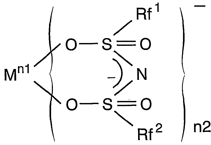
- the basic configuration of the light emitting device corresponds to the transparent solid support containing one or more of the rare earth complex groups having the following structural formula, and the f_f transition of the central ion of the complex. And a light emitting diode or a semiconductor laser that emits excitation light.
- M represents a rare earth atom
- nl represents 2 or 3.
- N2 is 2, 3 or represents a 4.
- Rf 'and Rf 2 are free of the same or different and each represents a hydrogen atom C
- ⁇ represents an aliphatic group, an aromatic group containing no hydrogen atom, or a heterocyclic group containing no hydrogen atom
- ⁇ and X 2 are the same or different and represent a group IVA atom, a VA group atom excluding nitrogen, and oxygen Group VIA atoms excluding And n3 and n4 each represent 0 or 1.
- Y represents C— ⁇ ′ ( ⁇ ′ represents a deuterium, a nitrogen atom or a hydrogen atom-containing 2 or less aliphatic group), N, P, As, Sb or Bi.
- X 1 is a carbon atom
- n3 is 0, and when X 2 is a carbon atom, n4 is 0.
- Rf and Rf 2 is hydrogen It is an aromatic group containing no atoms.
- Rf 3 is free of aromatic group or a hydrogen atom does not contain an aliphatic group Ci ⁇ C 22 containing no hydrogen atom, the hydrogen atom X 3 represents any one of a group IVA atom excluding carbon, a group VA atom excluding nitrogen, and a group VIA atom excluding oxygen, and n5 represents 0 or 1.
- M, nl and n2 are as defined above.
- Z ′ ′′ represents a hydrogen atom or ⁇ ′ ( ⁇ ′ is the same as above.)
- Rf 4 and Rf 5 are the same or Differently containing no hydrogen atom ⁇ ⁇ ( ⁇ aliphatic group, hydrogen atom-free aromatic group or hydrogen atom A heterocyclic group. )
- rare-earth complexes those having Rfl and Rf2 of up to about C1 or C2 are favorable in terms of affinity with the later-described transparent solid carrier plastic-polymer, and among them, particularly CF3 or CF2CF3 produces stable polymers.
- excitation light of ff transition of various rare earth ions can be arbitrarily generated, and highly efficient excitation of the center ion of the rare earth complex can be performed.
- the most commonly used transparent solid carriers are transparent resins. Since the resin is very lightweight and has excellent workability, the application range of the light emitting device according to the present invention is very wide.
- a polymer matrix described in [0069] of JP-A-2000-63682 can be used.
- a method for dispersing the above Eu complex in a transparent resin is described in [0070] of the publication.
- the rare-earth complex is not directly mixed into the transparent resin as described above, but once supported on a (host-guest) composite having an average particle size of nano- One guest)
- a complex in which a complex is mixed in a transparent resin, or a liquid containing the complex in a transparent container can also be used.
- the type and manufacturing method of the nano-sized (host-guest) complex supporting the rare earth complex are described in detail in JP-A-2000-256251.
- the rare earth complex is an organic complex containing the above-mentioned various ligands with a divalent, trivalent or tetravalent ion of a rare earth element as a central ion.
- the central ion emits light to be described later. By doing so, it functions as an optical material.
- Rare earth elements are scandium Sc (atomic number 21), yttrium Y (atomic number 39) and lanthanoids (atomic numbers 57 to 71: lanthanum La, cerium Ce, It is a collective term for the 17 elements: raceodymium Pr, neodymium Nd, promethium, samarium Sm, europium Eu, gadolinium Gd, terbium, dysprosium! ⁇ , Holmium Ho, erbium Er, thulium Tm, ytterbium Yb, lutetium. Rare earth elements are generally stable in compounds with an oxidation number of 3, but some of them are tetravalent in Ce and divalent in Sm, Eu, and Yb.
- the two elements before Sc and Y are the main transition elements that fill the 3d shell, and the 15 lanthanides are the inner transition elements that fill the 4f shell.
- Lanthanides have a ground electron configuration of (n_ 2) f ° M4 (n-l) s 2 (n- l) p 6 (n- l) d ° ⁇ 3 ⁇ 4s 2 (where n is 6 or 7).
- Rare earth elements are known to form many complexes, but in the complex, the energy level of the transition shell of the rare earth element is split, resulting in various energy levels.
- the transition between the energy levels in the 4f shell (ff transition) can be a useful optical material in practical use. That is the above-mentioned prior application.
- the present invention teaches the excitation means and further clarifies its specific application in order to further promote its practical use. That is, the rare earth complex optical material was regarded as a wavelength conversion element, and a light emitting diode or a semiconductor laser was used as the input. Then, the rare earth complex was supported on a transparent solid medium (carrier) so that it could be used as a specific optical element or optical component.
- the rare earth complex optical material was regarded as a wavelength conversion element, and a light emitting diode or a semiconductor laser was used as the input. Then, the rare earth complex was supported on a transparent solid medium (carrier) so that it could be used as a specific optical element or optical component.
- Light emitting diodes have a relatively narrow emission wavelength range.
- the excitation range of the rare-earth complex is extremely narrow (lnm or less) because the excitation is exclusively due to the trif transition of the specific ion of the complex ion which is the central ion. Therefore, by adjusting the emission wavelength of the light emitting diode to the excitation wavelength of the complex, the energy of the light emitting diode can be efficiently used for exciting the complex, the wavelength can be converted, and the light can be emitted as light of a longer wavelength.
- the emission wavelength range of the light emitting diode is not as narrow as the excitation wavelength range of the rare earth complex, part of the light of the light emitting diode is not used for excitation.
- the light emitting device which is a combination of the light emitting diode and the rare earth complex substance (carrier), the light emitted from the light emitting diode and the mixed light of the rare earth complex are emitted.
- Eu is an element belonging to the lanthanoid with atomic number 63, and its trivalent ion Eu 3+ can increase the ff transition excitation energy at wavelengths around 394, 420, and 465 nm (all blue) by properly designing the ligand.
- the radiant energy can be set to a wavelength around 600 to 700 nm (red light).
- excitation at a wavelength of 394 nm has particularly high luminous efficiency.
- a specific wavelength value for example, “394 nm”
- the width is narrow, not more than lnm, regardless of the type of ligand physicochemically. It includes the width of the degree.
- the wavelength of the fluorescence emission may include a large number of transitions between levels due to physicochemical factors, and thus the width may be as large as 10 nm or more.
- a nitride semiconductor LED or a semiconductor laser represented by the general formula In x Ga x x N (0 ⁇ x ⁇ 1) can control light of any wavelength in the blue to ultraviolet region by controlling its component variable X. It can be emitted, but when the Eu complex is used as the rare earth complex, the component variable X for generating the excitation light at wavelengths around 394, 420, and 465 nm is about 0.1 to 0.5. .
- the mixed light of the light-emitting diode with the blue + Eu complex and the red light of the light-emitting diode and the yellow + Eu complex of the light-emitting diode + Eu complex are further combined by combining the Y phosphor. A mixed light is obtained.
- the emission spectrum is formed from three bands of 599.8 nm, 611.6 nm and 697 nm. Since the relative intensity ratio between these emission bands can be changed depending on the host material of the metal complex, it is possible to control the color tone from orange to red.
- the excitation spectrum in FIG. 4 is composed of the band of the Eu ff transition absorption.
- the excitation peak at 394 mn is a sharp and strong band.
- a combination with a light emitting diode is also effective, but wavelength conversion is particularly effectively performed by using an InGaN-based semiconductor laser having a narrow emission half width.
- the InGaN-based laser diode is a device with an optical output of 2 (W) in the 390-410 nm band, and a high output characteristic of 400 mW or more has been reported at the laboratory level. Therefore, it emits at 394 nm.
- the combination of a high-power semiconductor laser and an Eu 3+ complex can achieve ultra-bright red light emission.This device is not only effective as an illumination device, but also a laser-excited diode. High impact as spray application.
- the absorption band in the 340 to 360 nm, 370 to 385 nm, or 460 to 475 nm region, or the background absorption in other wavelength regions is relatively broad, so that the combination with the light emitting diode is also effective.
- the absorption band in the 460 to 475 nm region almost matches the current InGaN blue emission band of white LEDs, so the Eu concentration is adjusted appropriately to produce a red phosphor and applied to the white LED. Then, a part of the blue light is converted to red fluorescence, and a white light emission spectrum with a slightly lower color temperature and improved color rendering in the red region can be realized.
- the emission wavelength range of Eu 3+ was orange to red, but by arranging another rare earth element ion at the central ion M of the rare earth complex represented by the general formulas (I) to (VI), Light emission of various colors can be obtained.
- Tb 3+ emits green light (excitation wavelengths 304 and 280 nm; emission wavelengths 490, 543, 580 and 620 nm), and Eu "and Ce 3+ emit blue light.
- a light emitting device of each color can be manufactured.
- White LED (correlated color temperature: 6500K) comprising a first drawing YAG phosphor coated with nitride Gariumu based blue LED and scan Bae spectrum of a standard light D 65 (correlated color temperature: 6504 K) scan Bae spectrum Dara off of.
- Fig. 2 Table of color rendering index of white LEDs and other white light sources.
- FIG. 3 is a graph of the emission spectrum of the Eu (pins) 3 complex.
- FIG. 4 is a graph of the excitation spectrum of the Eu (pms) 3 complex.
- Fig. 5 A graph showing the results of measuring the spectrum of transmitted light by covering an InGaN blue LED with a central emission wavelength of 394M1 with poly (methyl methacrylate) carrying a Eu (pms) 3 complex.
- Fig. 6 Graph showing the results of measuring the spectrum of transmitted light by covering an InGaN blue LED with a central emission wavelength of 465MI over a methyl methacrylate (PMMA) supporting Eu (pms) 3 complex.
- PMMA methyl methacrylate
- Fig. 7 Eu (puis) 3 complex is overlaid on a white LED in which an InGaN blue LED is covered with a YAG phosphor.
- 5 is a graph showing the result of measuring the spectrum of the transmitted light.
- FIG. 8 shows a light emitting device in which a blue InGaN-LED and a YAG phosphor are sealed in a plastic case containing an Eu complex, which is one embodiment of the present invention.
- FIG. 9 is a schematic configuration diagram of an automobile brake lamp including a semiconductor laser and a Eu complex-containing plastic cover, which is another embodiment of the present invention.
- Fig. 5 shows the measurement of the spectrum of the transmitted light of polymethyl methacrylate (PMMA) carrying the above Eu (pms) 3 complex over InGaN purple LED.
- the InGaN-LED is obtained by adjusting the component variable X so that the center of the emission wavelength is 394 nm.As intended, the LED has a relatively narrow emission peak in the range of 390 to 410 nm. , A sharp absorption peak due to the Eu complex occurs. In addition, a large emission peak due to the Eu complex appears at 611 nm, and a small emission peak appears near 591 nm. When this excitation light is used, a high luminous efficiency of about 50 to 70% can be obtained.
- FIG. 6 shows the result of the same measurement performed by adjusting the component variable X of the InGaN-LED so as to cover 465 nm, which is another excitation light of the Eu complex.
- a steep absorption peak of 465 nm due to the Eu complex occurs, and the emission peak appears near 611 M1, but the emission efficiency due to this excitation wavelength is not so large.
- the peak at 591 nm hardly appears.
- Fig. 7 shows the results of the same measurement performed by covering the above-mentioned Eu complex on a conventional white LED (an InGaN blue LED covered with a YAG phosphor).
- a conventional white LED an InGaN blue LED covered with a YAG phosphor.
- the absorption peak due to the Eu complex is clearly observed.
- a slightly smaller emission peak appears near 615 M1.
- the light-emitting device fabricated in this way is close to the ideal white color that supplements the red component missing in the conventional white LED, and the light source using it has a very high color rendering. It becomes a white light source with high performance. It can be used as a useful light source in fields where color discrimination or color rendering is particularly required, such as surgery and product displays. That is, the light emitting device according to the present invention is used in the field of medical lighting, the field of lighting in museums and restaurants, and In the field of indoor lighting.
- this light emitting device As a specific shape of this light emitting device, as shown in FIG. 8, it is preferable to have the same shape as a conventional bullet-shaped white LED light emitting device.
- the conventional bullet-shaped white LED light-emitting device is a device in which the InGaN-LED 81 is covered with a YAG phosphor 82 and sealed in a bullet-shaped epoxy resin package 83. However, it also plays the role of a lens that collects light emitted from the LED (through the YAG phosphor). By mixing the Eu complex in the package resin 83, a light emitting device 80 as one embodiment of the present invention is obtained. In this way, by adopting the same shape as before, the white LED light emitting device conventionally used in various places can be replaced with the light emitting device according to the present invention as it is, and there is a great economic effect of inheriting assets. be able to.
- a light emitting device having characteristics different from those described above can be obtained by combining the rare earth complex with a semiconductor laser.
- Semiconductor lasers have extremely narrow emission wavelengths. Therefore, by matching the emission wavelength with the excitation wavelength of the rare-earth complex, it is possible to obtain a light-emitting device that converts all the light of the semiconductor laser into light of another wavelength and emits only the light of the rare-earth complex.
- this light emitting device The features of this light emitting device are that the rare earth complex can be supported on various resins and the like, and that the excitation means is a light and compact semiconductor laser. This opens up a wide range of practical applications. As an example, it can be used for a car brake lamp.
- a plastic cover 91 (also referred to as a lens) carrying the rare-earth complex is provided at the rear (in the case of a brake lamp) of the car 90, and the same wavelength as the excitation light is emitted behind it.
- Semiconductor laser 92 to be disposed. Then, when the brake 93 is not depressed, the appearance of plastic such as transparent or white is exhibited. When the brake 93 is depressed, the semiconductor laser 92 emits light, the wavelength is converted by the plastic cover 91, and the color is red. Light will be emitted backward from the car 90.
- a diffusion plate (diffuser) 94 for diffusing the laser light is provided in front of the semiconductor laser 92.
- More compact brake lamps are also conceivable.
- the periphery of the flat plastic cover 95 carrying the rare-earth complex is surrounded by a reflective wall 96, and the semiconductor laser 97 is mounted at one place around the same.
- Light to plastic power It should be fired obliquely in a par 95 flat plate.
- the laser light is repeatedly reflected by the surrounding reflective wall 96, and while passing through the plastic cover 95, the wavelength is converted by the rare earth complex carried there, and the red light (other light) is emitted.
- light of a unique color such as blue or green
- the application example of the light emitting device according to the present invention has been described above, but the application example is not limited to the above.
- it can be used for a decorative panel installed in a store or the like, a backlight or a sidelight for a liquid crystal display device such as a personal computer, a portable terminal, and a mobile phone.
- a liquid crystal display device such as a personal computer, a portable terminal, and a mobile phone.
- Various other applications are possible within the spirit and scope of the present invention.
Landscapes
- Chemical & Material Sciences (AREA)
- Engineering & Computer Science (AREA)
- Materials Engineering (AREA)
- Organic Chemistry (AREA)
- Led Device Packages (AREA)
Abstract
Description
技術分野 Technical field
本発明は、 希土類錯体から成る有機蛍光体を含む波長変換物質と、 それを励起 する発光ダイオード又は半導体レーザとを組み合わせた発光装置に関する。 明 The present invention relates to a light emitting device in which a wavelength conversion material containing an organic phosphor composed of a rare earth complex is combined with a light emitting diode or a semiconductor laser that excites the wavelength converting material. Light
背景技術 Background art
発光ダイォード (LED) の特徴の一つは、 単色性が高い (すなわち、 スペクトル ピークの半値幅が狭い) ことである。 この特書徴を利用して、 赤 (R) 緑 (G) 青 ( B) 色からなる LED発光体を平面上に縦横に配列実装したフルカラー表示装置は既 に広く用いられている。 この場合、 RGB各色の強度比により表示色を任意に制御し ている。 One of the features of light emitting diodes (LEDs) is that they are highly monochromatic (ie, have a narrow spectral bandwidth at half maximum). Utilizing this special feature, full-color display devices in which red (R) green (G) blue (B) color LED emitters are mounted vertically and horizontally on a plane are already widely used. In this case, the display color is arbitrarily controlled by the intensity ratio of each RGB color.
しかし、 表示装置としてではなく、 照明装置としてみた場合、 LEDには未だ多く の問題が残されている。 上記のように、 RGBの LED発光体を配列した装置を使用し 、 RGB各色の強度比を適宜に設定することにより白色光を得ることもできるが、 照 明装置としてみた場合、 従来の照明装置である白熱電球や蛍光灯と比較すると、 (1)装置が大がかりになる、 (2) RGB各色を独立に制御しなければならない、 (3) 「 演色性」 が悪い、 等の問題がある。 However, LEDs still have many problems when viewed as lighting devices rather than as display devices. As described above, white light can be obtained by using a device in which RGB LED light emitters are arranged and setting the intensity ratio of each RGB color appropriately, but when viewed as a lighting device, a conventional lighting device Compared with the incandescent lamps and fluorescent lamps, there are problems such as (1) the scale of the device is large, (2) the RGB colors must be controlled independently, and (3) the "color rendering properties" are poor.
ここで 「演色性」 とは、 光源で物体を照明したときに物体がどのような色に見 えるかという、 その光源の性質のことをいう。 照明装置における演色性の重要性 に鑑み、 CIE (Commi ss i on Internat i onal e de l ' Ec l ai rage、 国際照明委員会) は 1964年に演色性評価方法を定めた。 これによると、 評価対象光源の色温度によつ て選ぶことのできる基準光源のシリーズを定め、 その基準光源と評価対象光源と で規定の試験色を照明したときの色ずれから演色評価数 Raが定められるようにな つている。 演色評価数 Raは 0〜100の値をとり、 100のときに評価対象光源は色の見 え方において基準光源と一致する。 基準光源としては、 色温度 5000K以下は完全放 射体を、 5000Kを超えるときは昼光の分光分布の計算値 (合成昼光という) を用い る。 試験色としては、 一般用として、 所定の分光反射率を有する 8色が選ばれて おり、 これにより計算される演色評価数は平均演色評価数と呼ばれる。 その他に 、 特殊目的用として 7色が選ばれており、 その中には、 日本人の肌色が含まれて いる。 これにより計算される演色評価数は特殊演色評価数と呼ばれる。 更に詳し くは、 「照明工学」 (社団法人電気学会編、 オーム社刊、 p. 36から) を参照され たい。 Here, “color rendering” refers to the nature of the light source, such as what color the object looks like when the object is illuminated by the light source. In light of the importance of color rendering in lighting systems, the CIE (Commissions Internationale Il e de l'Eclairage, International Commission on Illumination) established a method for evaluating color rendering in 1964. According to this, a series of reference light sources that can be selected according to the color temperature of the light source to be evaluated is determined, and the color rendering index Ra is calculated from the color shift when the test light source illuminates the test light with the reference light source and the light source to be evaluated. Are stipulated. The color rendering index Ra takes a value of 0 to 100. When the color rendering index is 100, the light source to be evaluated matches the reference light source in terms of color appearance. As a reference light source, a perfect radiator is used for color temperatures of 5000K or lower, and a calculated value of the spectral distribution of daylight (referred to as synthetic daylight) is used for a temperature exceeding 5000K. You. As test colors, eight colors having a predetermined spectral reflectance are selected for general use, and the color rendering index calculated by this is called an average color rendering index. In addition, seven colors have been selected for special purposes, including the Japanese skin color. The color rendering index calculated in this way is called a special color rendering index. For more details, see “Lighting Engineering” (edited by the Institute of Electrical Engineers of Japan, published by Ohmsha, p. 36).
演色性評価の際に完全放射体の光を基準とするのは、 自然光 (太陽光) が完全 - 放射体の光に近いからである。 完全放射体の発する光には、 各波長の光が連続的 に含まれる。 対象物の色合いは、 対象物の波長毎の光反射率 (分光反射率) によ り決定されるので、 照明光 (発光体) の分光分布において各波長の光が連続的に 含まれ、 かつ、 その強度分布が完全放射体のそれに近いものであれば、 対象物の 色の見え方は自然光下でのそれに近いものとなる。 しかし、 RGBで構成した LED白 色発光体は、 たとえ各色の強度比を調節することにより総体として白色光を発光 させたとしても、 その分光分布は連続的ではなく、 R (赤) 、 G (緑) 、 B (青) の 3波長の箇所にのみ狭い幅のピークを持つ不連続なものである。 この不連続性ゆ え、 RGB— LED発光体は照明装置として十分な演色性を持つことができない。 The reason why the color rendering properties are evaluated based on the light of the perfect radiator is that natural light (sunlight) is close to that of the perfect-radiator. The light emitted by the perfect radiator includes light of each wavelength continuously. Since the color of the object is determined by the light reflectance (spectral reflectance) for each wavelength of the object, the light of each wavelength is continuously included in the spectral distribution of the illumination light (luminous body), and However, if the intensity distribution is close to that of a perfect radiator, the color appearance of the object will be similar to that under natural light. However, even if the LED white light emitter composed of RGB emits white light as a whole by adjusting the intensity ratio of each color, its spectral distribution is not continuous, and R (red), G ( It is discontinuous with narrow peaks only at three wavelengths, green (green) and B (blue). Because of this discontinuity, RGB-LED emitters cannot have sufficient color rendering properties as lighting devices.
単一の LEDを用いた白色照明用光源としては、 現在、 窒化ガリウム系青色 LEDを YAG蛍光体で覆った (或いは塗布した) ものが考案されている (特開平 5- 152609公 報参照) 。 これは、 窒化ガリウム系青色 LEDの InGaN活性層からの青色光 (波長 46 Onm) を用いて YAG蛍光体を光励起し、 その蛍光体からの蛍光である黄色発光と LE Dからの青色との混色により白色光を得るというものである。 As a light source for white illumination using a single LED, a gallium nitride blue LED covered (or coated) with a YAG phosphor has been devised (see Japanese Patent Application Laid-Open No. 5-152609). This is because the YAG phosphor is photo-excited using blue light (wavelength 46 Onm) from the InGaN active layer of a gallium nitride blue LED, and the color mixture of the yellow light, which is the fluorescence from the phosphor, and the blue light from the LED. To obtain white light.
第 1図に、 YAG蛍光体を塗布した窒化ガリウム系青色 LEDからなる白色 LED (相関色 温度: 6500K) のスぺクトルと、 標準光 Ik (相関色温度: 6504K) のスぺクトルを示 す。 ここで標準光^とは、 色温度 6504Kの昼光を代表する演色評価用標準光であり、 自然昼光分光分布の実測値の統計処理によって CIEにより定められたものである。 白 色 LEDのスぺクトル分布は、 演色評価用標準光 D ^比較して、 紫色〜青紫領域 、 青緑 〜緑色領域及び赤色領域のスぺクトル分布が低くなつている。 第 2図に白色 LEDの演 色評価数を示しているが、 スぺクトル分布に対応して、 青紫、 緑及び赤色の特殊演 色評価数が劣っていることがわかる。 従って、 応用する分野によって必要とされる スぺクトル成分を何らかの形で補強し、 対象物の演色性を高める必要がある。 Fig. 1 shows a spectrum of a white LED (correlated color temperature: 6500K) consisting of a gallium nitride blue LED coated with a YAG phosphor and a spectrum of standard light Ik (correlated color temperature: 6504K). . Here, the standard light ^ is a standard light for color rendering evaluation representative of daylight having a color temperature of 6504K, and is determined by the CIE through statistical processing of measured values of the natural daylight spectral distribution. As for the spectral distribution of the white LED, the spectral distribution in the purple to blue-violet region, the blue-green to green region, and the red region is lower than that of the color rendering standard light D ^. Fig. 2 shows the color rendering index of the white LED. It can be seen that the special color rendering indexes of blue-violet, green and red are inferior to the spectral distribution. Therefore, depending on the field of application It is necessary to reinforce the spectral component in some way to enhance the color rendering of the object.
一例として、 医療応用分野に関して述べる。 2000年 9月 11日、 京都府立与謝の海病 院において、 白色 LED照明装置を用いた世界で初めての外科手術 (慢性腎不全患者に 対する内シャント造設術) を行い、 成功した。 この照明装置は、 YAG蛍光体を塗布し た窒化ガリゥム系青色 LEDからなる白色 LEDチップをアレイ状に並べて発光体パネル とし、 これをプラスチックゴーグルに実装して作製したものである。 この手術は、 バッテリ一駆動下で充分の照度を得て行われたもので、 外科医が装着可能なハンデ ィ一な照明機器として白色 LEDの有用性を実証したものである。 As an example, we will discuss the medical application field. On September 11, 2000, the world's first surgical operation using a white LED lighting device (internal shunting for a patient with chronic renal failure) was successfully performed at the Kyoto Prefectural Yosei Hospital. This illuminating device is made by arranging white LED chips made of a gallium nitride blue LED coated with a YAG fluorescent material in an array to form a light emitting panel, and mounting this on plastic goggles. This operation was performed with sufficient illuminance under one-battery operation, demonstrating the usefulness of white LEDs as a handy lighting device that surgeons can wear.
しかし上記手術の際、 白色 LEDの演色性について、 例えば動脈 (鮮明な赤色) と静 脈 (黒っぽい赤色) の血管 (黒っぽい赤色) が見分けにくいということが指摘され た。 このことは、 用いられた白色 LEDの赤色領域での演色性に問題があるためであり 、 597〜640mnの赤みがかったオレンジ色や 640〜780nmの赤色領域のスぺクトルを強 くすることで解決することができると考えられる。 However, it was pointed out that, during the above-mentioned operation, it was difficult to distinguish between the color rendering properties of the white LED, for example, arteries (clear red) and veins (dark red) of the veins (dark red). This is because there is a problem in the color rendering properties of the used white LED in the red region, and it is solved by increasing the spectrum of the red region of 597 to 640 nm or reddish region of 640 to 780 nm. It is thought that it can be done.
赤色領域のスぺクトルを強くする手段としては、 AlGalnP系 LED或いは AlGaAs系 L EDを白色 LEDチップの中に平面上に縦横に分布させることがまず考えられる。 しかし 、 発光スペクトルを放射面内で均等に混ぜ合わせるためには、 チップの実装をでき るだけ密に均等に分布させたり、 LED発光体パネル表面に拡散板を実装したりする必 要が生じる。 しかも、 白色 LED (YAG蛍光体塗布—窒化ガリウム系青色 LED) と赤色 LED (AlGalnP系 LED或いは AlGaAs系 LED) の強度を独立に制御しなくてはならない。 上記問題を生じることなく赤色領域のスぺクトルを強くする最も簡単な方法は、 現状の白色 LEDに赤色領域にて発光する蛍光体を塗布することである。 しかし、 広く 一般に使用される照明装置を対象とする場合、 その赤色蛍光体としては高効率でし かも安定性が高いことが必須の要件となる。 しかも、 加工性が高い点や、 人体に対 して有毒な成分を含んでおらず、 投棄されても地球環境を汚染するような物質を含 んでいない点も重要な要件である。 As a means for strengthening the spectrum in the red region, it is conceivable to first distribute an AlGalnP-based LED or an AlGaAs-based LED on a plane in a white LED chip vertically and horizontally. However, in order to mix the emission spectra evenly in the radiation plane, it is necessary to distribute the chips as densely and evenly as possible, or to mount a diffusion plate on the surface of the LED light emitting panel. Moreover, the intensity of the white LED (YAG phosphor coated—gallium nitride blue LED) and red LED (AlGalnP LED or AlGaAs LED) must be controlled independently. The easiest way to increase the spectrum in the red region without causing the above problems is to apply a phosphor emitting in the red region to a current white LED. However, in the case of lighting equipment widely used in general, it is essential that the red phosphor has high efficiency but high stability. In addition, it is also an important requirement that it has high processability, does not contain components that are toxic to the human body, and does not contain substances that, if discarded, would pollute the global environment.
赤色領域の蛍光体として、 例えば口一ダミン等の有機分子材料を用いれば高い発 光効率が得られるが、 光照射により容易に分解 ·退光が生じるため実用に適さない 。 ZnCdS :Ag系及び Y202S :Eu系蛍光体はテレビのブラウン管赤色蛍光体 (電子線励起 ) として用いられており、 紫外域の LED光源 (360〜380nm) で比較的高い赤色変換が 得られる。 しかしながら、 青色励起では充分な変換効率が得られないため、 現在用 いられている白色 LED ( YAG蛍光体塗布ー窒化ガリウム系青色 LED) と組み合わせる ことはできない。 現状の紫外 LEDの発光効率が青色 LEDと比較して格段に低い点を考 えると、 これも実用的な組み合わせとはならない。 しかも、 これら蛍光体は真空に 封じ切られていたブラウン管内でのみ長期安定性が得られるのであって、 大気中の 環境では吸湿が生じ、 光化学反応が加速され、 蛍光体の劣化が発生するという問題 が生じる。 これを解決するための封止技術は未だ開発されていない。 さらに、 ZnC dS :Ag系は Cdを含んでおり、 環境への影響が危惧される。 Although high luminous efficiency can be obtained by using an organic molecular material such as mono-damine as a phosphor in the red region, it is not suitable for practical use because it is easily decomposed and quenched by light irradiation. ZnCdS: Ag-based and Y 2 0 2 S: Eu phosphor is used as a cathode ray tube red phosphor television (electron beam excitation), a relatively high red conversion in ultraviolet region of the LED light source (360~380Nm) can get. However, blue excitation does not provide sufficient conversion efficiency, so it cannot be combined with currently used white LEDs (YAG phosphor-coated gallium nitride blue LEDs). Considering that the luminous efficiency of the current ultraviolet LED is much lower than that of the blue LED, this is not a practical combination either. In addition, these phosphors can achieve long-term stability only in a cathode ray tube that has been sealed off in a vacuum. In the air environment, moisture absorption occurs, photochemical reactions are accelerated, and phosphor degradation occurs. Problems arise. A sealing technique for solving this has not yet been developed. In addition, the ZnC dS: Ag system contains Cd, and its effects on the environment are concerned.
このようなことを考えると、 現状の白色 LEDと組み合わせ可能な赤色蛍光体に関し ては、 これまで開発されてきた蛍光体は種々の問題をかかえている。 Considering this, regarding the red phosphor that can be combined with the current white LED, the phosphor that has been developed so far has various problems.
従来、 無機酸化物や無機硫化物等の物質中に Eu (ユーロピウム) 、 Tb (テルビゥ ム) や Tm (ツリウム) 等の希土類金属を添加することで種々の蛍光材料が開発され てきた。 しかし、 従来、 量子物理学のエネルギーギャップ理論より、 「希土類金属 は有機媒体の中では発光しにくい」 とされ、 実際、 近年までプラスチック系などの 有機媒体中での希土類金属の発光効率は非常に低かった。 Conventionally, various fluorescent materials have been developed by adding rare earth metals such as Eu (europium), Tb (terbium) and Tm (thulium) to substances such as inorganic oxides and inorganic sulfides. However, the energy gap theory of quantum physics has traditionally stated that "rare earth metals do not easily emit light in organic media." In fact, until recently, the luminous efficiency of rare earth metals in organic media such as plastics has been extremely low. It was low.
これに対し、 本件発明者の一部はエネルギーギャップ理論の再検討から始めるこ とにより、 1995年に世界で初めて、 有機媒体中で発光可能なネオジム等の希土類金 属の一群の錯体の設計に成功した (長谷川靖哉, 「有機媒体中で光らないネオジゥム をどのように光らせるか?」,化学と工業,第 53巻(2000)第 2号, p. 126-130) 。 こ れらの一部については特許出願も行った (PCT/JP98/0097OW098/40388公報、 特願 平 10- 238973=特開 2000-63682公報、 特願平 11- 62298=特開 2000-256251.公報) 。 これら錯体は、 350°Cという高温においても安定であり光劣化が生じにくく、 有機 化合物は熱や光照射によって劣化が生じやすいという従来の常識を覆すものである 。 また、 プラスチックやポリマーという樹脂系のホスト材料との親和性も高く、 容 易な加工性と相まつて次世代の光素子となることが期待されている。 In contrast, some of the inventors of the present invention have begun to reexamine the energy gap theory, and in 1995 the world's first design of a group of complexes of rare earth metals such as neodymium, which can emit light in organic media. Succeeded (Yasuya Hasegawa, "How to shine a neodymium that does not shine in organic media?", Chemistry and Industry, Vol. 53 (2000) No. 2, p. 126-130). A patent application was also filed for some of these (PCT / JP98 / 0097OW098 / 40388, Japanese Patent Application No. 10-238973 = Japanese Patent Application Laid-Open No. 2000-63682, Japanese Patent Application No. 11-62298 = Japanese Patent Application No. 2000-256251. Gazette). These complexes are stable even at a high temperature of 350 ° C, and are unlikely to undergo photodegradation, and break the conventional wisdom that organic compounds tend to be degraded by heat or light irradiation. In addition, it has high affinity with resin-based host materials such as plastics and polymers, and is expected to be a next-generation optical device in combination with easy processability.
本発明は、 まずは前記の演色性の高い白色 LEDを実現するために、 これら錯体中の 特にその目的に適した物質を選択して利用したものであり、 InGaN系発光層を有する 発光ダイオード或いは半導体レ一ザを、 希土類イオンの有機金属錯体、 或いは、 こ れら金属錯体を含むナノサイズのホストーゲスト複合体、 或いはこれら金属錯体又 は複合体を含む透明ポリマーで覆うことにより、 高演色性照明用白色 LEDを実現した ものである。 The present invention first uses and selects a substance suitable for the purpose among these complexes in order to realize the white LED having a high color rendering property, and uses a light emitting diode or a semiconductor having an InGaN-based light emitting layer. The laser may be used as an organometallic complex of a rare earth ion, a nano-sized host-guest complex containing these metal complexes, or a metal complex or a metal complex thereof. Has realized a white LED for high color rendering illumination by covering it with a transparent polymer containing a complex.
しかし本発明の射程はそれに止まらない。 本件発明者らは、 上記希土類錯体の励 起光の波長範囲がきわめて狭いことから、 それが高効率の波長変換発光デバィスと なり得ることに着目した。 すなわち、 上記希土類錯体と、 同様に発光波長範囲が比 較的狭い発光ダイォード、 又は発光波長幅が同様にきわめて狭い半導体レーザと組 み合わせることにより、 総体として非常に高効率かつ高輝度の発光装置として利用 し得ることに想到した。 しかも、 発光ダイオード又は半導体レーザは非常に小型で ある上、 希土類錯体はプラスチックやポリマーとの親和性が良いことから、 小型軽 量かつ高寿命の各種発光装置として実用上広い応用範囲を有することに思い至り、 本発明を世に出すこととしたものである。 発明の開示 However, the range of the present invention does not stop there. The present inventors have paid attention to the fact that the wavelength range of the excitation light of the rare-earth complex is extremely narrow, so that it can be a highly efficient wavelength-converted light-emitting device. In other words, by combining the rare earth complex with a light emitting diode having a relatively narrow emission wavelength range or a semiconductor laser having a similarly narrow emission wavelength width, a light emitting device having very high efficiency and high brightness as a whole is obtained. I thought that it could be used as In addition, light-emitting diodes or semiconductor lasers are very small, and rare-earth complexes have good affinity for plastics and polymers, so they have a wide range of practical applications as small, lightweight, and long-lasting light-emitting devices. He decided to bring the present invention to the world. Disclosure of the invention
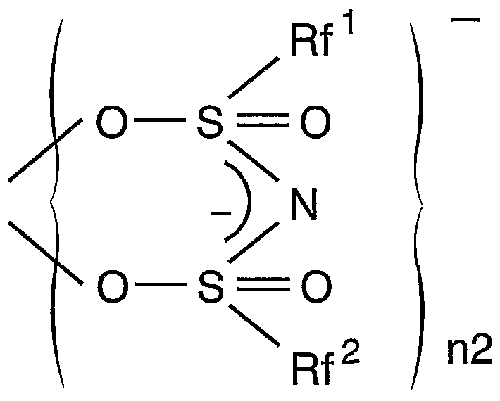
従って、 本発明に係る発光装置の基本的構成は、 下記構造式を有する希土類錯 体群の中の 1種又は 2種以上を含む透明固体担体と、 該錯体の中心イオンの f_f遷 移に対応する励起光を発する発光ダイオード又は半導体レーザとを組み合わせた ことを特徴とするものである。 Therefore, the basic configuration of the light emitting device according to the present invention corresponds to the transparent solid support containing one or more of the rare earth complex groups having the following structural formula, and the f_f transition of the central ion of the complex. And a light emitting diode or a semiconductor laser that emits excitation light.
一般式(I) General formula (I)

(この式において、 Mは希土類原子を示し、 nlは 2又は 3を示す。 n2は 2、 3又 は 4を示す。 Rf'及び Rf2は、 同一又は異なって水素原子を含まない C,〜(^の脂肪族 基、 水素原子を含まない芳香族基又は水素原子を含まないヘテロ環基を示し; ϊ及 び X2は、 同一又は異なって IVA族原子、 窒素を除く VA族原子、 酸素を除く VIA族原子 のいずれかを示し、 n3及び n4は、 0又は 1を示す。 Yは、 C— Ζ' (Ζ'は重水素、 ノ\ ロゲン原子又は水素原子を含まない 〜 2の脂肪族基を示す) 、 N、 P、 As、 Sb又は Biを示す。 但し、 X1が炭素原子のとき n3は 0であり、 X2が炭素原子のとき n4は 0で あり、 X1と X2とが同時に炭素原子の場合、 Rf , Rf 2の少なくとも一方は水素原子を含 まない芳香族基である。 ) (In this formula, M represents a rare earth atom, nl represents 2 or 3. N2 is 2, 3 or represents a 4. Rf 'and Rf 2 are free of the same or different and each represents a hydrogen atom C, ~ (^ Represents an aliphatic group, an aromatic group containing no hydrogen atom, or a heterocyclic group containing no hydrogen atom; ϊ and X 2 are the same or different and represent a group IVA atom, a VA group atom excluding nitrogen, and oxygen Group VIA atoms excluding And n3 and n4 each represent 0 or 1. Y represents C—Ζ ′ (Ζ ′ represents a deuterium, a nitrogen atom or a hydrogen atom-containing 2 or less aliphatic group), N, P, As, Sb or Bi. However, when X 1 is a carbon atom, n3 is 0, and when X 2 is a carbon atom, n4 is 0.When X 1 and X 2 are both carbon atoms, at least one of Rf and Rf 2 is hydrogen It is an aromatic group containing no atoms. )
一般式(I I) General formula (II)

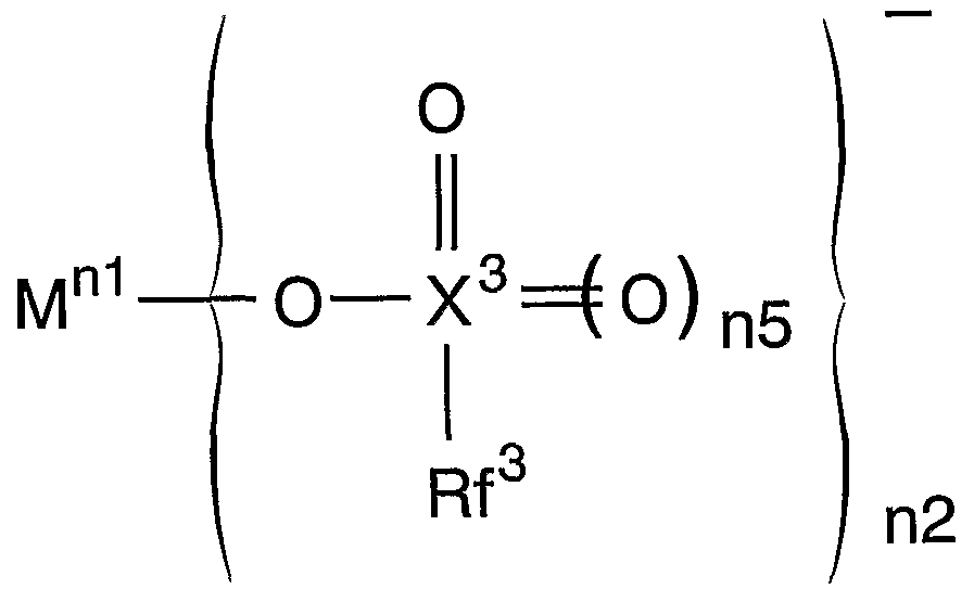
(この式において、 M、 nl及び n2は前記に定義された通りである。 Rf 3は水素原子 を含まない Ci〜C22の脂肪族基、 水素原子を含まない芳香族基又は水素原子を含まな いへテロ環基を示し; X3は、 炭素を除く IVA族原子、 窒素を除く VA族原子、 酸素を 除く VIA族原子のいずれかを示す。 n5は 0又は 1を示す。 ) (In this formula, M, nl and n2 are as defined above. Rf 3 is free of aromatic group or a hydrogen atom does not contain an aliphatic group Ci~C 22 containing no hydrogen atom, the hydrogen atom X 3 represents any one of a group IVA atom excluding carbon, a group VA atom excluding nitrogen, and a group VIA atom excluding oxygen, and n5 represents 0 or 1.)
一般式(I I I) General formula (I I I)

(この式において、 M、 Rf1, Rf2、 nl及び n2は前記に定義された通りである。 ) 一般式(IV)
(この式において、 M、 Rf, Rf2, nl及び n2は前記に定義された通りである。 ) -般式 (V) (In this formula, M, Rf, Rf 2 , nl and n2 are as defined above.)-General formula (V)

(この式において、 M、 Rf1, Rf2、 nl、 n2及び Z'は前記に定義された通りである,(In this formula, M, Rf 1 , Rf 2 , nl, n2 and Z ′ are as defined above,
) )
一般式 (VI) General formula (VI)

(この式において、 M、 nl及び n2は前記に定義された通りである。 Z' 'は、 水素 原子又は Ζ' (Ζ'は前記に同じ) を示す。 Rf4及び Rf5は、 同一又は異なって水素原子 を含まない ^〜(^の脂肪族基、 水素原子を含まない芳香族基又は水素原子を含まな いへテロ環基を示す。 ) (In this formula, M, nl and n2 are as defined above. Z ′ ″ represents a hydrogen atom or Ζ ′ (Ζ ′ is the same as above.) Rf 4 and Rf 5 are the same or Differently containing no hydrogen atom ^ ~ (^ aliphatic group, hydrogen atom-free aromatic group or hydrogen atom A heterocyclic group. )
上記の水素原子を含まない 〜( 22の脂肪族基、 水素原子を含まない芳香族基、 水 素原子を含まないヘテロ環基、 及び X1、 X2、 X3の具体例は、 特開 2000-63682公報の [0031]〜 [0037]に記載されているので、 そちらを参照されたい。 また、 上記錯体 の合成法についても、 同公報の [0047]〜 [0067]に記載されている。 Specific examples of the above-mentioned hydrogen atom-free to ( 22 aliphatic groups, hydrogen-free aromatic groups, hydrogen-free heterocyclic groups, and X 1 , X 2 , and X 3 are described in It is described in [0031] to [0037] of 2000-63682, so please refer to that, and the synthesis method of the above complex is also described in [0047] to [0067] of the same publication. .
なお、 これらの希土類錯体の中では、 Rf l、 Rf 2が C1又は C2程度までのものが後 述の透明固体担体であるプラスチックゃポリマ一との親和性の点で良好であり、 その中でも特に CF3又は CF2CF3が安定なポリマーを生成する。 Among these rare-earth complexes, those having Rfl and Rf2 of up to about C1 or C2 are favorable in terms of affinity with the later-described transparent solid carrier plastic-polymer, and among them, particularly CF3 or CF2CF3 produces stable polymers.
上記希土類錯体を励起する発光体としては、 一般式 IihGanN OKxく 1)で表される発 光層を有する窒化物半導体発光ダイオード又はそれを用いた半導体レーザとする3 。 この成分変数 Xを変化させることにより、 各種希土類イオンの f-f遷移の励起光 を任意に生成することができ、 上記希土類錯体の中心イオンに対して効率の高い 励起を行うことができる。 The light emitter to excite the rare earth complex, 3, the nitride semiconductor light emitting diode or a semiconductor laser using the same having a light emission layer of the general formula IihGanN OKx rather 1). By changing the component variable X, excitation light of ff transition of various rare earth ions can be arbitrarily generated, and highly efficient excitation of the center ion of the rare earth complex can be performed.
上記透明固体担体として最も一般的に使用できるのは、 透明な樹脂である。 樹 脂は非常に軽量であり、 加工性に優れているため、 本発明に係る発光装置の応用 範囲が非常に広くなる。 透明樹脂としては、 上記特開 2000- 63682公報の [0069]に 記載されたポリマーマトリクスを使用することができる。 また、 上記 Eu錯体を透 明樹脂に分散させる方法は、 同公報の [0070]に記載されている。 The most commonly used transparent solid carriers are transparent resins. Since the resin is very lightweight and has excellent workability, the application range of the light emitting device according to the present invention is very wide. As the transparent resin, a polymer matrix described in [0069] of JP-A-2000-63682 can be used. A method for dispersing the above Eu complex in a transparent resin is described in [0070] of the publication.
透明固体担体としては、 上記のように希土類錯体を透明樹脂に直接混入したも のではなく、 一旦平均粒径がナノサイズの (ホスト一ゲスト) 複合体に担持させ た後、 そのナノサイズ (ホスト一ゲスト) 複合体を透明樹脂に混入したり、 それ を含有する液体を透明容器に入れたものも使用することもできる。 希土類錯体を 担持させたナノサイズ (ホスト一ゲスト) 複合体の種類及び製造方法については 、 特開 2000- 256251公報に詳細に記載されている。 As the transparent solid carrier, the rare-earth complex is not directly mixed into the transparent resin as described above, but once supported on a (host-guest) composite having an average particle size of nano- One guest) A complex in which a complex is mixed in a transparent resin, or a liquid containing the complex in a transparent container can also be used. The type and manufacturing method of the nano-sized (host-guest) complex supporting the rare earth complex are described in detail in JP-A-2000-256251.
希土類錯体とは、 希土類元素の 2価、 3価又は 4価のイオンを中心イオンとし て上記各種配位子を含む有機錯体であり、 本発明ではこの中心イオンが後述の光 励起 ·光放出を行うことにより、 光学材料として機能する。 The rare earth complex is an organic complex containing the above-mentioned various ligands with a divalent, trivalent or tetravalent ion of a rare earth element as a central ion. In the present invention, the central ion emits light to be described later. By doing so, it functions as an optical material.
希土類元素は周期表 I I I族に属するスカンジウム Sc (原子番号 21)、 イットリウム Y (原子番号 39)及びランタノイド(原子番号 57〜71:ランタン La, セリウム Ce, プ ラセオジム Pr, ネオジム Nd, プロメチウムお, サマリウム Sm, ユーロピウム Eu, ガドリニウム Gd, テルビウムお, ジスプロシウム!^, ホルミウム Ho, エルビウム Er, ツリウム Tm, イッテルビウム Yb, ルテチウムお) の 17元素の総称である。 希 土類元素は酸化数 3の化合物が一般に安定であるが, Ceでは 4価, Sm, Eu, Ybなどで は 2価をもつものもある。 原子構造からみると, Sc及び Yの前 2元素は 3d殻が充た されてゆく主遷移元素であり、 ランタノィド 15元素は 4f殻が充たされる内遷移元 素である。 ランタノィドは (n_ 2) f°M4 (n— l) s2 (n— l) p6 (n— l) d°~¾s2 (nは 6又は 7)の 基底電子配置をもつ。 Rare earth elements are scandium Sc (atomic number 21), yttrium Y (atomic number 39) and lanthanoids (atomic numbers 57 to 71: lanthanum La, cerium Ce, It is a collective term for the 17 elements: raceodymium Pr, neodymium Nd, promethium, samarium Sm, europium Eu, gadolinium Gd, terbium, dysprosium! ^, Holmium Ho, erbium Er, thulium Tm, ytterbium Yb, lutetium. Rare earth elements are generally stable in compounds with an oxidation number of 3, but some of them are tetravalent in Ce and divalent in Sm, Eu, and Yb. In terms of atomic structure, the two elements before Sc and Y are the main transition elements that fill the 3d shell, and the 15 lanthanides are the inner transition elements that fill the 4f shell. Lanthanides have a ground electron configuration of (n_ 2) f ° M4 (n-l) s 2 (n- l) p 6 (n- l) d ° ~ ¾s 2 (where n is 6 or 7).
希土類元素は多くの錯体を作ることが知られているが、 錯体内においては希土 類元素の遷移殻のエネルギー準位が分裂し、 種々のエネルギー準位が生じる。 希 土類元素とその周辺の配位子を適切に選択することにより、 この 4f殻内のエネル ギー準位間の遷移 (f- f遷移) が実用上、 有用な光学材料となり得ることを見いだ したのが前記先行出願である。 Rare earth elements are known to form many complexes, but in the complex, the energy level of the transition shell of the rare earth element is split, resulting in various energy levels. By appropriately selecting the rare earth element and its surrounding ligands, we see that the transition between the energy levels in the 4f shell (ff transition) can be a useful optical material in practical use. That is the above-mentioned prior application.
本件発明はその実用化を更に進めるべく、 その励起手段を教示するとともに、 その具体的応用を明確にしたものである。 すなわち、 上記希土類錯体光学材料を 波長変換素子として捉え、 その入力として発光ダイオード又は半導体レーザを用 いることとした。 そして、 具体的な光学素子,光学部品として使用可能とするた めに、 上記希土類錯体を透明な固体媒体 (担体) に担持させた。 The present invention teaches the excitation means and further clarifies its specific application in order to further promote its practical use. That is, the rare earth complex optical material was regarded as a wavelength conversion element, and a light emitting diode or a semiconductor laser was used as the input. Then, the rare earth complex was supported on a transparent solid medium (carrier) so that it could be used as a specific optical element or optical component.
発光ダイオードは、 その発光波長範囲が比較的狭い。 一方、 上記希土類錯体は、 励起が専らその中心イオンである錯体イオンの特定軌道の卜 f遷移によるため、 励起 波長の範囲が極めて狭い (l nm以下) 。 従って、 発光ダイオードの発光波長をその 錯体の励起波長に合わせることにより、 発光ダイォードのエネルギーを効率よく錯 体の励起に使用し、 波長変換して、 より長波長の光として放出させることができる 。 ここで、 発光ダイオードの発光波長範囲は希土類錯体の励起波長範囲ほどには狭 くないため、 発光ダイオードの光の一部は励起には使用されない。 従って、 本発明 に係る発光ダイオードと希土類錯体物質 (の担体) の組合せによる発光装置では、 発光ダイォードの光と希土類錯体の蛍光とが混合した光を放出することとなる。 Light emitting diodes have a relatively narrow emission wavelength range. On the other hand, the excitation range of the rare-earth complex is extremely narrow (lnm or less) because the excitation is exclusively due to the trif transition of the specific ion of the complex ion which is the central ion. Therefore, by adjusting the emission wavelength of the light emitting diode to the excitation wavelength of the complex, the energy of the light emitting diode can be efficiently used for exciting the complex, the wavelength can be converted, and the light can be emitted as light of a longer wavelength. Here, since the emission wavelength range of the light emitting diode is not as narrow as the excitation wavelength range of the rare earth complex, part of the light of the light emitting diode is not used for excitation. Therefore, in the light emitting device according to the present invention, which is a combination of the light emitting diode and the rare earth complex substance (carrier), the light emitted from the light emitting diode and the mixed light of the rare earth complex are emitted.
これを前述の高演色性白色 LEDに利用しょうとするのが本発明のもう一つの目的で あり、 その際には希土類元素としてユーロピウム (Eu) を用いる。 Euを用いた場合 の上記各錯体の構造式は次の通りとなる。 構造式 (le)It is another object of the present invention to utilize this in the above-described high color rendering white LED, and in that case, europium (Eu) is used as a rare earth element. When using Eu The structural formulas of the above complexes are as follows. Structural formula (le)

構造式 a I e)Structural formula a I e)

構造式(I l ie)Structural formula (I lie)
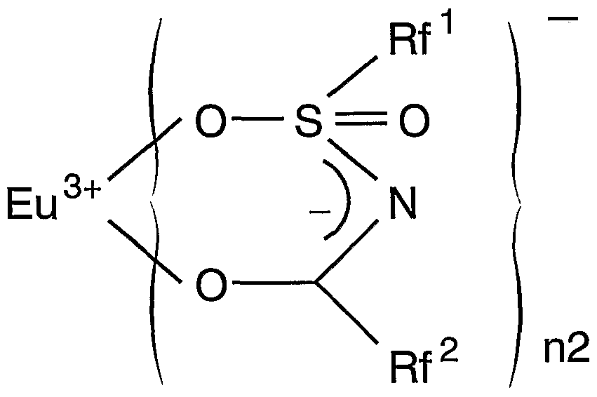
構造式(IVe) Structural formula (IVe)
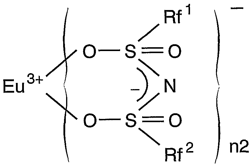


(上記構造式における Rf l、 Rf 2等は上記一般式(I)〜 (VI)において説明したものと同 じである。 ) (Rfl, Rf2, etc. in the above structural formula are the same as those described in the above general formulas (I) to (VI).)
Euはランタノイドに属する原子番号 63の元素であり、 その 3価イオン Eu3+は、 配 位子の設計を適切に行うことにより、 f-f遷移の励起エネルギーを波長 394、 420、 465nm付近 (いずれも青色) に、 放射エネルギーを波長 600〜700nm付近 (赤色光) にすることができる。 このうち、 波長 394nmにおける励起は特に発光効率が高い。 なお、 本明細書 (請求項を含む) において特定の波長の値 (例えば 「394nm」 ) を 挙げたとき、 その値の前後にはその物理的性質又は測定技術に応じた幅が存在す ることは当然である。 例えば、 その波長が希土類錯体の励起光の波長を指す場合 、 その幅は物理化学的には配位子の種類によらず前後 lnm以下の狭いものであるが 、 測定技術等を考慮すると数 MI程度の幅を含むものとなる。 また、 蛍光発光の波 長に関しては、 物理化学的に多数の準位間遷移の放出を含む場合があるため、 そ の幅は 10nm以上に及ぶ場合がある。 Eu is an element belonging to the lanthanoid with atomic number 63, and its trivalent ion Eu 3+ can increase the ff transition excitation energy at wavelengths around 394, 420, and 465 nm (all blue) by properly designing the ligand. In addition, the radiant energy can be set to a wavelength around 600 to 700 nm (red light). Of these, excitation at a wavelength of 394 nm has particularly high luminous efficiency. When a specific wavelength value (for example, “394 nm”) is mentioned in this specification (including claims), there must be a width corresponding to the physical property or measurement technique before and after that value. Is natural. For example, when the wavelength refers to the wavelength of the excitation light of the rare-earth complex, the width is narrow, not more than lnm, regardless of the type of ligand physicochemically. It includes the width of the degree. In addition, the wavelength of the fluorescence emission may include a large number of transitions between levels due to physicochemical factors, and thus the width may be as large as 10 nm or more.
一方、 一般式 InxGa卜 xN (0〈xく 1)で表わされる窒化物半導体 LED又は半導体レーザは 、 その成分変数 Xを制御することにより、 青色〜紫外域の任意の波長の光を放出さ せることができるが、 希土類錯体として Eu錯体を用いた場合には、 その波長 394、 420、 465nm付近の励起光を発生するための成分変数 Xは 0. 1〜0. 5程度となる。 On the other hand, a nitride semiconductor LED or a semiconductor laser represented by the general formula In x Ga x x N (0 <x × 1) can control light of any wavelength in the blue to ultraviolet region by controlling its component variable X. It can be emitted, but when the Eu complex is used as the rare earth complex, the component variable X for generating the excitation light at wavelengths around 394, 420, and 465 nm is about 0.1 to 0.5. .
これら両者を組み合わせることにより、 発光ダイォードの青色 +Eu錯体の赤色 との混合光が、 また、 更に Y蛍光体を組み合わせることにより、 発光ダイオードの 青色 + Y蛍光体の黄色 + Eu錯体の赤色との混合光が得られる。 By combining these two, the mixed light of the light-emitting diode with the blue + Eu complex and the red light of the light-emitting diode and the yellow + Eu complex of the light-emitting diode + Eu complex are further combined by combining the Y phosphor. A mixed light is obtained.
一例として、 上記構造式(IVe) (ただし、 Rf l =Rf2 = CF3、 n2= 3 ) を有する Eu ( pms) 3錯体 (pms -per f luorophenylmethaneパーフルオロフェニルメタン) の発光ス ベクトルと励起スペクトルを第 3図と第 4図に示す。 第 3図に示すように、 発光ス ぺクトルは 590. 8nm、 611. 6nm及び 697nmからなる三つのバンドから形成されている。 これら発光バンド間の相対強度比は、 金属錯体のホスト材料によって変化させるこ とができるので、 オレンジから赤色の色調を制御することが可能となる。 一方、 第 4図の励起スペクトルは、 Eu f- f遷移吸収のバンドから成っている。 これら f- f遷移は、 直接 Eu3+を光励起するため、 配位子やホスト材料の実キャリア励起による 劣化の問題が生じない。 特に、 394mnの励起ピークは急峻で強いバンドである。 この ため、 発光ダイオードとの組み合わせも有効であるが、 発光半値幅の狭い InGaN系半 導体レーザを用いれば特に有効に波長変換がなされる。 現在 InGaN系レーザダイォ一 ドは、 390〜410nm帯域の素子で光出力 2( Wのものが実用化され、 出力 400mW以上の高 出力特性も実験室レベルで報告されている。 従って、 394nmで発振する高出力半導体 レーザと Eu3+錯体の組み合わせによって超高輝度の赤色発光を実現することができる 。 このようなデバイスは、 照明装置として有効なだけではなく、 レーザ励起のディ スプレー応用としてもインパクトが高い。 As an example, the emission spectrum and the excitation spectrum of the Eu (pms) 3 complex (pms-perfluorophenylmethane) having the above structural formula (IVe) (where Rfl = Rf2 = CF 3 , n2 = 3) Are shown in FIGS. 3 and 4. As shown in FIG. 3, the emission spectrum is formed from three bands of 599.8 nm, 611.6 nm and 697 nm. Since the relative intensity ratio between these emission bands can be changed depending on the host material of the metal complex, it is possible to control the color tone from orange to red. On the other hand, the excitation spectrum in FIG. 4 is composed of the band of the Eu ff transition absorption. Since these ff transitions directly photoexcitate Eu 3+ , there is no problem of degradation due to actual carrier excitation of ligands and host materials. In particular, the excitation peak at 394 mn is a sharp and strong band. For this reason, a combination with a light emitting diode is also effective, but wavelength conversion is particularly effectively performed by using an InGaN-based semiconductor laser having a narrow emission half width. Currently, the InGaN-based laser diode is a device with an optical output of 2 (W) in the 390-410 nm band, and a high output characteristic of 400 mW or more has been reported at the laboratory level. Therefore, it emits at 394 nm. The combination of a high-power semiconductor laser and an Eu 3+ complex can achieve ultra-bright red light emission.This device is not only effective as an illumination device, but also a laser-excited diode. High impact as spray application.
一方、 340〜360nmや 370〜385nm或いは 460〜475nm域の吸収帯、 或いはその他の波 長域のバックグラウンド吸収は比較的ブロードであるので、 発光ダイォ一ドとの組 み合わせも有効となる。 特に、 460〜475nm域の吸収帯は、 現状の白色 LEDの InGaN青 色発光バンドとほぼ一致しているので、 Eu 濃度を適度に調整 して赤色蛍光体を作 製して白色 LED上に塗布すれば、 青色のうちの一部が赤色蛍光に変換され、 色温度を 少し下げるとともに、 赤色領域の演色性を高めた白色発光スぺクトルを実現するこ とができる。 On the other hand, the absorption band in the 340 to 360 nm, 370 to 385 nm, or 460 to 475 nm region, or the background absorption in other wavelength regions is relatively broad, so that the combination with the light emitting diode is also effective. In particular, the absorption band in the 460 to 475 nm region almost matches the current InGaN blue emission band of white LEDs, so the Eu concentration is adjusted appropriately to produce a red phosphor and applied to the white LED. Then, a part of the blue light is converted to red fluorescence, and a white light emission spectrum with a slightly lower color temperature and improved color rendering in the red region can be realized.
上記 Eu3+の発光波長域はォレンジ〜赤色であつたが、 上記一般式(I)〜 (VI)で表さ れる希土類錯体の中心イオン Mに他の希土類元素のイオンを配置することにより、 種々の色の発光を得ることができる。 例えば、 Tb3+は緑色 (励起波長 304、 280nm; 発光波長 490、 543、 580、 620nm) 、 Eu"や Ce3+は青色を発光するため、 これらの錯体 を上記透明固体担体に担持させ、 それぞれに適合した LEDで励起させることにより 、 各色の発光装置を作製することができる。 図面の簡単な説明 The emission wavelength range of Eu 3+ was orange to red, but by arranging another rare earth element ion at the central ion M of the rare earth complex represented by the general formulas (I) to (VI), Light emission of various colors can be obtained. For example, Tb 3+ emits green light (excitation wavelengths 304 and 280 nm; emission wavelengths 490, 543, 580 and 620 nm), and Eu "and Ce 3+ emit blue light. By exciting the LED with a suitable LED, a light emitting device of each color can be manufactured.
第 1図 YAG蛍光体を塗布した窒化ガリゥム系青色 LEDからなる白色 LED (相関色温 度: 6500K) のスぺクトルと、 標準光 D65 (相関色温度: 6504K) のスぺクトルのダラ フ。 White LED (correlated color temperature: 6500K) comprising a first drawing YAG phosphor coated with nitride Gariumu based blue LED and scan Bae spectrum of a standard light D 65 (correlated color temperature: 6504 K) scan Bae spectrum Dara off of.
第 2図 白色 LED及びその他の白色光源の演色評価数の表。 Fig. 2 Table of color rendering index of white LEDs and other white light sources.
第 3図 Eu (pins) 3錯体の発光スペクトルのグラフ。 FIG. 3 is a graph of the emission spectrum of the Eu (pins) 3 complex.
第 4図 Eu (pms) 3錯体の励起スペクトルのグラフ。 FIG. 4 is a graph of the excitation spectrum of the Eu (pms) 3 complex.
第 5図 中心発光波長 394M1の InGaN青色 LED上に、 Eu (pms) 3錯体を担持したポリ メチルメタクリレート (P匪 A)をかぶせ、 その透過光のスぺクトルを測定した結果 のグラフ。 Fig. 5 A graph showing the results of measuring the spectrum of transmitted light by covering an InGaN blue LED with a central emission wavelength of 394M1 with poly (methyl methacrylate) carrying a Eu (pms) 3 complex.
第 6図 中心発光波長 465MIの InGaN青色 LED上に Eu (pms) 3錯体を担持したポリメ チルメ夕クリレート (PMMA)をかぶせ、 その透過光のスペクトルを測定した結果の グラフ。 Fig. 6 Graph showing the results of measuring the spectrum of transmitted light by covering an InGaN blue LED with a central emission wavelength of 465MI over a methyl methacrylate (PMMA) supporting Eu (pms) 3 complex.
第 7図 InGaN青色 LEDを YAG蛍光体で覆った白色 LED上に Eu (puis) 3錯体をかぶせ、 その透過光のスぺクトルを測定した結果のグラフ。 Fig. 7 Eu (puis) 3 complex is overlaid on a white LED in which an InGaN blue LED is covered with a YAG phosphor. 5 is a graph showing the result of measuring the spectrum of the transmitted light.
第 8図 本発明の一実施例である、 Eu錯体を含有するプラスチックケースに青 色 I nGaN-LED及び YAG蛍光体が封入された発光装置。 FIG. 8 shows a light emitting device in which a blue InGaN-LED and a YAG phosphor are sealed in a plastic case containing an Eu complex, which is one embodiment of the present invention.
第 9図 本発明の別の実施例である、 半導体レーザと Eu錯体含有プラスチック カバーからなる自動車ブレーキランプの概略構成図。 発明を実施するための最良の形態 FIG. 9 is a schematic configuration diagram of an automobile brake lamp including a semiconductor laser and a Eu complex-containing plastic cover, which is another embodiment of the present invention. BEST MODE FOR CARRYING OUT THE INVENTION
第 5図は、 InGaN紫色 LEDの上に上記 Eu (pms) 3錯体を担持したポリメチルメタクリ レート (PMMA)をかぶせ、 その透過光のスペクトルを測定したものである。 InGaN -LEDは、 その発光波長の中心が 394nmとなるようにその成分変数 Xを調整したもの であり、 ねらい通り LEDは 390〜410nmの範囲で比較的狭い発光ピークを有するが、 その中で 394nmにおいて Eu錯体による急峻な吸収ピークが生じている。 また、 61 1 nmに Eu錯体による大きな発光ピークが現れており、 591 nm付近においても小さな発 光ピークが現れている。 この励起光を使用した場合、 50〜70 %程度の高い発光効 率が得られる。 Fig. 5 shows the measurement of the spectrum of the transmitted light of polymethyl methacrylate (PMMA) carrying the above Eu (pms) 3 complex over InGaN purple LED. The InGaN-LED is obtained by adjusting the component variable X so that the center of the emission wavelength is 394 nm.As intended, the LED has a relatively narrow emission peak in the range of 390 to 410 nm. , A sharp absorption peak due to the Eu complex occurs. In addition, a large emission peak due to the Eu complex appears at 611 nm, and a small emission peak appears near 591 nm. When this excitation light is used, a high luminous efficiency of about 50 to 70% can be obtained.
また、 第 6図は、 Eu錯体のもう一つの励起光である 465nmをカバーするように I nGaN- LEDの成分変数 Xを調整し、 同様の測定を行った結果である。 同様に、 LED発 光ピークの中で Eu錯体による 465nmの急峻な吸収ピークが生じており、 それによる 発光ピークが 61 1 M1付近に現れているが、 この励起波長による発光効率はそう大き くはないため、 591nmのピークはほとんど現れていない。 FIG. 6 shows the result of the same measurement performed by adjusting the component variable X of the InGaN-LED so as to cover 465 nm, which is another excitation light of the Eu complex. Similarly, among the LED emission peaks, a steep absorption peak of 465 nm due to the Eu complex occurs, and the emission peak appears near 611 M1, but the emission efficiency due to this excitation wavelength is not so large. As a result, the peak at 591 nm hardly appears.
第 7図は、 従来の白色 LED ( InGaN青色 LEDを YAG蛍光体で覆ったもの) の上に上 記 Eu錯体をかぶせて同様の測定を行つた結果である。 465nmにおいて Eu錯体による 吸収ピークが明瞭に認められる。 また、 その結果として、 61 5M1付近にやや小さい 発光ピークが現れている。 この図から明らかなように、 このようにして作製され る発光装置は、 従来の白色 LEDにおいて欠けていた赤色成分を補った理想的な白色 に近いものとなり、 それを用いた光源は非常に演色性の高い白色光源となる。 こ れは、 手術や商品ディスプレイ等、 色識別力或いは演色性が特に必要とされる分 野において有用な光源として利用することができる。 即ち、 本発明に係る発光装 置は、 医療用照明の分野、 美術館やレストラン等における照明の分野、 一般家庭 における室内照明の分野等に応用することができる。 Fig. 7 shows the results of the same measurement performed by covering the above-mentioned Eu complex on a conventional white LED (an InGaN blue LED covered with a YAG phosphor). At 465 nm, the absorption peak due to the Eu complex is clearly observed. As a result, a slightly smaller emission peak appears near 615 M1. As is evident from this figure, the light-emitting device fabricated in this way is close to the ideal white color that supplements the red component missing in the conventional white LED, and the light source using it has a very high color rendering. It becomes a white light source with high performance. It can be used as a useful light source in fields where color discrimination or color rendering is particularly required, such as surgery and product displays. That is, the light emitting device according to the present invention is used in the field of medical lighting, the field of lighting in museums and restaurants, and In the field of indoor lighting.
この発光装置の具体的形状としては、 第 8図に示すように、 従来の砲弾形白色 LED発光装置と同形状とすることが好ましい。 従来の砲弾形白色 LED発光装置は、 InGaN-LED 8 1上を YAG蛍光体 8 2で覆い、 砲弾形のエポキシ樹脂パッケージ 8 3 に封入したものであり、 砲弾形パッケージ 8 3は LEDの保護とともに、 LEDから ( YAG蛍光体を通って) 発する光を集光するレンズの役割も果たしている。 このパッ ケージ樹脂 8 3内に上記 Eu錯体を混入することにより、 本発明の一実施例として の発光装置 8 0となる。 このように従来と同一の形状とすることにより、 従来よ り各所で用いられていた白色 LED発光装置をそのまま本発明に係る発光装置に置き 換えることができ、 資産継承の大きな経済的効果を挙げることができる。 As a specific shape of this light emitting device, as shown in FIG. 8, it is preferable to have the same shape as a conventional bullet-shaped white LED light emitting device. The conventional bullet-shaped white LED light-emitting device is a device in which the InGaN-LED 81 is covered with a YAG phosphor 82 and sealed in a bullet-shaped epoxy resin package 83. However, it also plays the role of a lens that collects light emitted from the LED (through the YAG phosphor). By mixing the Eu complex in the package resin 83, a light emitting device 80 as one embodiment of the present invention is obtained. In this way, by adopting the same shape as before, the white LED light emitting device conventionally used in various places can be replaced with the light emitting device according to the present invention as it is, and there is a great economic effect of inheriting assets. be able to.
次に、 上記希土類錯体を半導体レーザと組み合わせることにより、 上記とは別の 特性を持つ発光装置を得ることができる。 半導体レーザは、 その発光波長の幅が極 めて狭い。 従って、 その発光波長を上記希土類錯体の励起波長と合致させることに より、 半導体レーザの光を全て別の波長の光に変換し、 希土類錯体の光だけを放射 する発光装置とすることができる。 Next, a light emitting device having characteristics different from those described above can be obtained by combining the rare earth complex with a semiconductor laser. Semiconductor lasers have extremely narrow emission wavelengths. Therefore, by matching the emission wavelength with the excitation wavelength of the rare-earth complex, it is possible to obtain a light-emitting device that converts all the light of the semiconductor laser into light of another wavelength and emits only the light of the rare-earth complex.
この発光装置の特長は、 上記希土類錯体が種々の樹脂等に担持させることができ るという点と、 その励起手段が軽量 ·コンパクトな半導体レーザであるという点に ある。 これは実用上、 広い応用範囲を拓くものである。 一例として、 自動車のブレ —キランプ等に使用することが考えられる。 The features of this light emitting device are that the rare earth complex can be supported on various resins and the like, and that the excitation means is a light and compact semiconductor laser. This opens up a wide range of practical applications. As an example, it can be used for a car brake lamp.
第 9図に示すように、 自動車 9 0の後部 (ブレーキランプの場合) に上記希土類 錯体を担持したプラスチックカバー 9 1 (レンズとも言う) を設け、 その背後に、 その励起光と同じ波長を放出する半導体レーザ 9 2を配置する。 すると、 ブレーキ 9 3を踏まない時は透明又は白色等のプラスチックの外観を呈し、 ブレーキ 9 3を 踏んだときは半導体レーザ 9 2が発光して、 プラスチックカバ一 9 1により波長変 換され、 赤色光が自動車 9 0から後方に発せられるようになる。 なお、 半導体レー ザ 9 2の前方には、 レーザ光を拡散する拡散板 (ディフューザ) 9 4を設ける。 よりコンパクトなプレーキランプも考えられる。 第 9図(c)に示すように、 上記 希土類錯体を担持した平板状プラスチックカバー 9 5の周囲を反射壁 9 6で囲み 、 半導体レ一ザ 9 7をその周囲の 1力所に取り付け、 レーザ光をプラスチック力 パー 9 5の平板内で斜め方向に発射させるようにしておく。 こうすることにより 、 レ一ザ光は周囲の反射壁 9 6で反射を繰り返し、 プラスチックカバ一 9 5内を 通過するうちに、 そこに担持された希土類錯体で波長変換され、 赤色光 (他の希 土類元素を用いた場合には、 青色、 緑色等のそれぞれ固有の色の光) がプラスチ ックカバー 9 5の表面から放出される。 なお、 自動車のブレーキランプのように 後方のみに光を発する場合には、 他の面には反射板を設けておくことが望ましい が、 ドアの表示灯等として用いる場合には、 両面から光を放出するようにしてお いてもよい。 As shown in Fig. 9, a plastic cover 91 (also referred to as a lens) carrying the rare-earth complex is provided at the rear (in the case of a brake lamp) of the car 90, and the same wavelength as the excitation light is emitted behind it. Semiconductor laser 92 to be disposed. Then, when the brake 93 is not depressed, the appearance of plastic such as transparent or white is exhibited. When the brake 93 is depressed, the semiconductor laser 92 emits light, the wavelength is converted by the plastic cover 91, and the color is red. Light will be emitted backward from the car 90. In addition, a diffusion plate (diffuser) 94 for diffusing the laser light is provided in front of the semiconductor laser 92. More compact brake lamps are also conceivable. As shown in FIG. 9 (c), the periphery of the flat plastic cover 95 carrying the rare-earth complex is surrounded by a reflective wall 96, and the semiconductor laser 97 is mounted at one place around the same. Light to plastic power It should be fired obliquely in a par 95 flat plate. By doing so, the laser light is repeatedly reflected by the surrounding reflective wall 96, and while passing through the plastic cover 95, the wavelength is converted by the rare earth complex carried there, and the red light (other light) is emitted. When a rare earth element is used, light of a unique color such as blue or green) is emitted from the surface of the plastic cover 95. In addition, when light is emitted only to the rear like a brake light of a car, it is desirable to provide a reflector on the other surface.However, when used as an indicator for doors, etc., light is emitted from both surfaces. It may be released.
以上、 本発明に係る発光装置の一応用例を説明したが、 応用例は上記のものに 限られない。 例えば、 店舗等に設置する装飾用のパネルや、 パソコン ·携帯端末 •携帯電話等の液晶表示装置用バックライト又はサイドライト等に使用すること も可能である。 この他にも、 本発明の精神及び範囲内で様々な応用例を考えるこ とが可能である。 The application example of the light emitting device according to the present invention has been described above, but the application example is not limited to the above. For example, it can be used for a decorative panel installed in a store or the like, a backlight or a sidelight for a liquid crystal display device such as a personal computer, a portable terminal, and a mobile phone. Various other applications are possible within the spirit and scope of the present invention.
Claims


Priority Applications (2)
| Application Number | Priority Date | Filing Date | Title |
|---|---|---|---|
| US10/476,456 US20040137265A1 (en) | 2001-05-02 | 2002-05-01 | Light emitting apparatus |
| JP2002588643A JP3897110B2 (en) | 2001-05-02 | 2002-05-01 | Light emitting device |
Applications Claiming Priority (2)
| Application Number | Priority Date | Filing Date | Title |
|---|---|---|---|
| JP2001135116 | 2001-05-02 | ||
| JP2001-135116 | 2001-05-02 |
Publications (1)
| Publication Number | Publication Date |
|---|---|
| WO2002091487A1 true WO2002091487A1 (en) | 2002-11-14 |
Family
ID=18982647
Family Applications (1)
| Application Number | Title | Priority Date | Filing Date |
|---|---|---|---|
| PCT/JP2002/004349 Ceased WO2002091487A1 (en) | 2001-05-02 | 2002-05-01 | Light emitting apparatus |
Country Status (3)
| Country | Link |
|---|---|
| US (1) | US20040137265A1 (en) |
| JP (1) | JP3897110B2 (en) |
| WO (1) | WO2002091487A1 (en) |
Cited By (19)
| Publication number | Priority date | Publication date | Assignee | Title |
|---|---|---|---|---|
| JP2005079500A (en) * | 2003-09-03 | 2005-03-24 | Lite-On Technology Corp | White light emitting device |
| WO2005075598A1 (en) * | 2004-02-06 | 2005-08-18 | Mitsubishi Chemical Corporation | Light emitting device and lighting device using it, image display unit |
| WO2005078811A1 (en) * | 2004-02-18 | 2005-08-25 | National Institute For Materials Science | Light emitting device and lighting fixture |
| JP2006108661A (en) * | 2004-09-30 | 2006-04-20 | Agilent Technol Inc | Light source using wavelength conversion material |
| JP2006222404A (en) * | 2005-02-14 | 2006-08-24 | Kri Inc | Light emitting device |
| JP2006222403A (en) * | 2005-02-14 | 2006-08-24 | Kri Inc | Optical amplifier |
| JP2006219646A (en) * | 2005-02-14 | 2006-08-24 | Kri Inc | Light control optical element |
| US7282160B2 (en) * | 2003-05-22 | 2007-10-16 | Mitsubishi Chemical Corporation | Light emitting device and fluorescent material |
| JP2007311114A (en) * | 2006-05-17 | 2007-11-29 | Olympus Corp | Lighting optical system using solid light emitting element emitting white light, and optical device equipped with it |
| JPWO2006004187A1 (en) * | 2004-07-05 | 2008-04-24 | 株式会社Kri | Organic inorganic composite |
| JP2009289957A (en) * | 2008-05-29 | 2009-12-10 | Yamaguchi Univ | Semiconductor light-emitting device and imaging device |
| US7795797B2 (en) | 2005-03-23 | 2010-09-14 | Stanley Electric Co., Ltd. | Phosphor with laminated coating, its manufacture method and light emitting device using the same |
| JP2011204406A (en) * | 2010-03-24 | 2011-10-13 | Caravell Co Ltd | Combination lighting of light-emitting diode and phosphor |
| WO2012073699A1 (en) * | 2010-11-29 | 2012-06-07 | 日立化成工業株式会社 | Rare earth metal complex |
| US8400011B2 (en) | 2009-10-14 | 2013-03-19 | Sharp Kabushiki Kaisha | Illumination device, automotive lighting equipment, and vehicle |
| CN102995154A (en) * | 2012-11-22 | 2013-03-27 | 青岛大学 | Preparation method of rare earth fluorescence micro-nano fiber array |
| JP2014039053A (en) * | 2006-01-16 | 2014-02-27 | Philips Lumileds Lightng Co Llc | Phosphor conversion semiconductor light emitting device |
| US20150180202A1 (en) * | 2012-03-22 | 2015-06-25 | Toshiba Lighting & Technology Corporation | Solid-State Lighting Device |
| US9261259B2 (en) | 2011-06-30 | 2016-02-16 | Sharp Kabushiki Kaisha | Laser-beam utilization device and vehicle headlight |
Families Citing this family (17)
| Publication number | Priority date | Publication date | Assignee | Title |
|---|---|---|---|---|
| DE10351081A1 (en) * | 2003-10-31 | 2005-06-09 | Lite-On Technology Co. | White light-emitting device, has two phosphors emitting respective yellow and red lights with preset wavelengths upon excitation by blue or blue-green LED, where yellow and red lights are mixed to white light |
| JP2007165728A (en) * | 2005-12-15 | 2007-06-28 | Toshiba Discrete Technology Kk | Light emitting device and lighting device for visible light communication |
| US8125327B2 (en) * | 2008-09-11 | 2012-02-28 | Edward J. Ognibene | Method for increasing vehicle brake/safety/hazard light visibility |
| US9250044B1 (en) | 2009-05-29 | 2016-02-02 | Soraa Laser Diode, Inc. | Gallium and nitrogen containing laser diode dazzling devices and methods of use |
| US9800017B1 (en) * | 2009-05-29 | 2017-10-24 | Soraa Laser Diode, Inc. | Laser device and method for a vehicle |
| JP4888853B2 (en) | 2009-11-12 | 2012-02-29 | 学校法人慶應義塾 | Method for improving visibility of liquid crystal display device, and liquid crystal display device using the same |
| CN102959459B (en) | 2010-06-22 | 2019-06-18 | 东洋纺株式会社 | Liquid crystal display device, polarizing plate and polarizing plate protective film |
| TWI551919B (en) | 2011-05-18 | 2016-10-01 | 東洋紡績股份有限公司 | Liquid-crystal display device |
| TWI542907B (en) | 2011-05-18 | 2016-07-21 | 東洋紡績股份有限公司 | Liquid crystal device, polarizing plate and polarizer protection film |
| US10879673B2 (en) | 2015-08-19 | 2020-12-29 | Soraa Laser Diode, Inc. | Integrated white light source using a laser diode and a phosphor in a surface mount device package |
| US11437774B2 (en) | 2015-08-19 | 2022-09-06 | Kyocera Sld Laser, Inc. | High-luminous flux laser-based white light source |
| US10938182B2 (en) | 2015-08-19 | 2021-03-02 | Soraa Laser Diode, Inc. | Specialized integrated light source using a laser diode |
| US11239637B2 (en) | 2018-12-21 | 2022-02-01 | Kyocera Sld Laser, Inc. | Fiber delivered laser induced white light system |
| US11421843B2 (en) | 2018-12-21 | 2022-08-23 | Kyocera Sld Laser, Inc. | Fiber-delivered laser-induced dynamic light system |
| US12000552B2 (en) | 2019-01-18 | 2024-06-04 | Kyocera Sld Laser, Inc. | Laser-based fiber-coupled white light system for a vehicle |
| US11884202B2 (en) | 2019-01-18 | 2024-01-30 | Kyocera Sld Laser, Inc. | Laser-based fiber-coupled white light system |
| US12152742B2 (en) | 2019-01-18 | 2024-11-26 | Kyocera Sld Laser, Inc. | Laser-based light guide-coupled wide-spectrum light system |
Citations (7)
| Publication number | Priority date | Publication date | Assignee | Title |
|---|---|---|---|---|
| JPS6178003A (en) * | 1984-09-25 | 1986-04-21 | 株式会社小糸製作所 | Lamp apparatus for vehicle |
| JPH06224474A (en) * | 1993-01-26 | 1994-08-12 | Rohm Co Ltd | Surface light emitting display device |
| US5711592A (en) * | 1994-10-25 | 1998-01-27 | Honda Giken Kogyo Kabushiki Kaisha | Lamplight device for vehicle |
| WO1998040388A1 (en) * | 1997-03-11 | 1998-09-17 | New Japan Chemical Co., Ltd. | Rare earth complexes |
| JPH1180165A (en) * | 1997-09-03 | 1999-03-26 | New Japan Chem Co Ltd | Rare earth element complex |
| US6051925A (en) * | 1997-03-03 | 2000-04-18 | U.S. Philips Corporation | Diode-addressed color display with molecular phosphor |
| GB2347018A (en) * | 1999-02-18 | 2000-08-23 | Hewlett Packard Co | White light emitting devices |
-
2002
- 2002-05-01 US US10/476,456 patent/US20040137265A1/en not_active Abandoned
- 2002-05-01 JP JP2002588643A patent/JP3897110B2/en not_active Expired - Fee Related
- 2002-05-01 WO PCT/JP2002/004349 patent/WO2002091487A1/en not_active Ceased
Patent Citations (7)
| Publication number | Priority date | Publication date | Assignee | Title |
|---|---|---|---|---|
| JPS6178003A (en) * | 1984-09-25 | 1986-04-21 | 株式会社小糸製作所 | Lamp apparatus for vehicle |
| JPH06224474A (en) * | 1993-01-26 | 1994-08-12 | Rohm Co Ltd | Surface light emitting display device |
| US5711592A (en) * | 1994-10-25 | 1998-01-27 | Honda Giken Kogyo Kabushiki Kaisha | Lamplight device for vehicle |
| US6051925A (en) * | 1997-03-03 | 2000-04-18 | U.S. Philips Corporation | Diode-addressed color display with molecular phosphor |
| WO1998040388A1 (en) * | 1997-03-11 | 1998-09-17 | New Japan Chemical Co., Ltd. | Rare earth complexes |
| JPH1180165A (en) * | 1997-09-03 | 1999-03-26 | New Japan Chem Co Ltd | Rare earth element complex |
| GB2347018A (en) * | 1999-02-18 | 2000-08-23 | Hewlett Packard Co | White light emitting devices |
Cited By (24)
| Publication number | Priority date | Publication date | Assignee | Title |
|---|---|---|---|---|
| US7396488B2 (en) * | 2003-05-22 | 2008-07-08 | Mitsubishi Chemical Corporation | Light emitting device and fluorescent material |
| US7282160B2 (en) * | 2003-05-22 | 2007-10-16 | Mitsubishi Chemical Corporation | Light emitting device and fluorescent material |
| JP2005079500A (en) * | 2003-09-03 | 2005-03-24 | Lite-On Technology Corp | White light emitting device |
| WO2005075598A1 (en) * | 2004-02-06 | 2005-08-18 | Mitsubishi Chemical Corporation | Light emitting device and lighting device using it, image display unit |
| WO2005078811A1 (en) * | 2004-02-18 | 2005-08-25 | National Institute For Materials Science | Light emitting device and lighting fixture |
| US7573190B2 (en) | 2004-02-18 | 2009-08-11 | National Institute For Materials Science | Light emitting element and lighting instrument |
| CN100483756C (en) * | 2004-02-18 | 2009-04-29 | 独立行政法人物质·材料研究机构 | Light emitting device and lighting fixture |
| JP4731485B2 (en) * | 2004-07-05 | 2011-07-27 | 株式会社Kri | Organic inorganic composite |
| JPWO2006004187A1 (en) * | 2004-07-05 | 2008-04-24 | 株式会社Kri | Organic inorganic composite |
| JP2006108661A (en) * | 2004-09-30 | 2006-04-20 | Agilent Technol Inc | Light source using wavelength conversion material |
| JP2006219646A (en) * | 2005-02-14 | 2006-08-24 | Kri Inc | Light control optical element |
| JP2006222403A (en) * | 2005-02-14 | 2006-08-24 | Kri Inc | Optical amplifier |
| JP2006222404A (en) * | 2005-02-14 | 2006-08-24 | Kri Inc | Light emitting device |
| US7795797B2 (en) | 2005-03-23 | 2010-09-14 | Stanley Electric Co., Ltd. | Phosphor with laminated coating, its manufacture method and light emitting device using the same |
| JP2014039053A (en) * | 2006-01-16 | 2014-02-27 | Philips Lumileds Lightng Co Llc | Phosphor conversion semiconductor light emitting device |
| JP2007311114A (en) * | 2006-05-17 | 2007-11-29 | Olympus Corp | Lighting optical system using solid light emitting element emitting white light, and optical device equipped with it |
| JP2009289957A (en) * | 2008-05-29 | 2009-12-10 | Yamaguchi Univ | Semiconductor light-emitting device and imaging device |
| US8400011B2 (en) | 2009-10-14 | 2013-03-19 | Sharp Kabushiki Kaisha | Illumination device, automotive lighting equipment, and vehicle |
| JP2011204406A (en) * | 2010-03-24 | 2011-10-13 | Caravell Co Ltd | Combination lighting of light-emitting diode and phosphor |
| WO2012073699A1 (en) * | 2010-11-29 | 2012-06-07 | 日立化成工業株式会社 | Rare earth metal complex |
| JP2012116762A (en) * | 2010-11-29 | 2012-06-21 | Hitachi Chemical Co Ltd | Rare earth metal complex |
| US9261259B2 (en) | 2011-06-30 | 2016-02-16 | Sharp Kabushiki Kaisha | Laser-beam utilization device and vehicle headlight |
| US20150180202A1 (en) * | 2012-03-22 | 2015-06-25 | Toshiba Lighting & Technology Corporation | Solid-State Lighting Device |
| CN102995154A (en) * | 2012-11-22 | 2013-03-27 | 青岛大学 | Preparation method of rare earth fluorescence micro-nano fiber array |
Also Published As
| Publication number | Publication date |
|---|---|
| US20040137265A1 (en) | 2004-07-15 |
| JPWO2002091487A1 (en) | 2004-08-26 |
| JP3897110B2 (en) | 2007-03-22 |
Similar Documents
| Publication | Publication Date | Title |
|---|---|---|
| JP3897110B2 (en) | Light emitting device | |
| JP6306264B2 (en) | PC-LED module with improved white rendering and conversion efficiency | |
| KR101488551B1 (en) | Light-emitting device, vehicular lighting fixture comprising the device, and head lamp | |
| US6805600B2 (en) | Method of manufacturing white light source | |
| JP2000509912A (en) | White light emitting diode | |
| US20050093422A1 (en) | White light-emitting device | |
| JP4932248B2 (en) | Yellow light emitting phosphor, white light emitting element using the same, and illumination device using the same | |
| JP2008503087A (en) | LED with improved light emissivity profile | |
| CN107001931A (en) | light emitting device | |
| CN101220272A (en) | Nitride fluorescent material emitting red light and white light emitting device using same | |
| TW200849669A (en) | White light-emitting lamp and illuminating device using the same | |
| US10205066B2 (en) | White phosphor converted LED with stable flux output versus temperature | |
| JP6223988B2 (en) | Phosphor, light emitting device and lighting device | |
| JP2005072479A (en) | White light emitting device, phosphor and method for producing the same | |
| JP2012501365A (en) | RED PHOSPHOR FOR SOLID LIGHTING AND METHOD FOR PRODUCING THE SAME {REDPHOSPHORANDITOSING | |
| KR20190013976A (en) | Lutetium nitride-based fluorescent powder and light emitting element having the same | |
| WO2003042325A1 (en) | Optical functional material employing rare earth complex and light emitting device | |
| JP2005079500A (en) | White light emitting device | |
| KR100902988B1 (en) | Manufacturing method of white light emitting diode | |
| US7229332B2 (en) | Method for manufacturing white light source | |
| JP2004182969A (en) | Phosphor powder composition and method for producing high brightness white light emitting diode using the phosphor powder composition | |
| JP4219621B2 (en) | Manufacturing method of white light emitting diode | |
| TWI266563B (en) | Compound, phosphor composition and light-emitting device containing the same | |
| JP4098354B2 (en) | White light emitting device | |
| JP2008311670A (en) | White light emitting diode |
Legal Events
| Date | Code | Title | Description |
|---|---|---|---|
| AK | Designated states |
Kind code of ref document: A1 Designated state(s): AE AG AL AM AT AU AZ BA BB BG BR BY BZ CA CH CN CO CR CU CZ DE DK DM DZ EC EE ES FI GB GD GE GH GM HR HU ID IL IN IS JP KE KG KP KR KZ LC LK LR LS LT LU LV MA MD MG MK MN MW MX MZ NO NZ OM PH PL PT RO RU SD SE SG SI SK SL TJ TM TN TR TT TZ UA UG US UZ VN YU ZA ZM ZW |
|
| AL | Designated countries for regional patents |
Kind code of ref document: A1 Designated state(s): GH GM KE LS MW MZ SD SL SZ TZ UG ZM ZW AM AZ BY KG KZ MD RU TJ TM AT BE CH CY DE DK ES FI FR GB GR IE IT LU MC NL PT SE TR BF BJ CF CG CI CM GA GN GQ GW ML MR NE SN TD TG |
|
| 121 | Ep: the epo has been informed by wipo that ep was designated in this application | ||
| DFPE | Request for preliminary examination filed prior to expiration of 19th month from priority date (pct application filed before 20040101) | ||
| WWE | Wipo information: entry into national phase |
Ref document number: 10476456 Country of ref document: US Ref document number: 2002588643 Country of ref document: JP |
|
| REG | Reference to national code |
Ref country code: DE Ref legal event code: 8642 |
|
| 122 | Ep: pct application non-entry in european phase |