JP2007311114A - Lighting optical system using solid light emitting element emitting white light, and optical device equipped with it - Google Patents
Lighting optical system using solid light emitting element emitting white light, and optical device equipped with it Download PDFInfo
- Publication number
- JP2007311114A JP2007311114A JP2006137776A JP2006137776A JP2007311114A JP 2007311114 A JP2007311114 A JP 2007311114A JP 2006137776 A JP2006137776 A JP 2006137776A JP 2006137776 A JP2006137776 A JP 2006137776A JP 2007311114 A JP2007311114 A JP 2007311114A
- Authority
- JP
- Japan
- Prior art keywords
- predetermined wavelength
- transmittance
- optical system
- wavelength region
- value
- Prior art date
- Legal status (The legal status is an assumption and is not a legal conclusion. Google has not performed a legal analysis and makes no representation as to the accuracy of the status listed.)
- Pending
Links
- 230000003287 optical effect Effects 0.000 title claims abstract description 162
- 239000007787 solid Substances 0.000 title claims abstract description 16
- 238000009826 distribution Methods 0.000 claims abstract description 114
- 238000006243 chemical reaction Methods 0.000 claims abstract description 56
- 238000002834 transmittance Methods 0.000 claims description 112
- 238000005286 illumination Methods 0.000 claims description 97
- 229910052736 halogen Inorganic materials 0.000 abstract description 25
- 150000002367 halogens Chemical class 0.000 abstract description 25
- 238000003745 diagnosis Methods 0.000 abstract description 13
- 238000001514 detection method Methods 0.000 abstract 1
- 230000007170 pathology Effects 0.000 abstract 1
- 230000003595 spectral effect Effects 0.000 description 20
- 230000005284 excitation Effects 0.000 description 5
- 238000009877 rendering Methods 0.000 description 5
- 230000000052 comparative effect Effects 0.000 description 4
- 238000010586 diagram Methods 0.000 description 4
- 239000007850 fluorescent dye Substances 0.000 description 4
- 238000003384 imaging method Methods 0.000 description 4
- 238000003780 insertion Methods 0.000 description 4
- 230000037431 insertion Effects 0.000 description 4
- 239000013307 optical fiber Substances 0.000 description 3
- 201000010099 disease Diseases 0.000 description 2
- 208000037265 diseases, disorders, signs and symptoms Diseases 0.000 description 2
- 238000007689 inspection Methods 0.000 description 2
- 230000001575 pathological effect Effects 0.000 description 2
- 208000002177 Cataract Diseases 0.000 description 1
- 230000001154 acute effect Effects 0.000 description 1
- 230000005540 biological transmission Effects 0.000 description 1
- 239000002775 capsule Substances 0.000 description 1
- 230000007547 defect Effects 0.000 description 1
- 229910003460 diamond Inorganic materials 0.000 description 1
- 239000010432 diamond Substances 0.000 description 1
- 239000003365 glass fiber Substances 0.000 description 1
- 230000001678 irradiating effect Effects 0.000 description 1
- 238000010827 pathological analysis Methods 0.000 description 1
- 230000035699 permeability Effects 0.000 description 1
- 230000011514 reflex Effects 0.000 description 1
- 238000001356 surgical procedure Methods 0.000 description 1
- 238000009827 uniform distribution Methods 0.000 description 1
- 230000000007 visual effect Effects 0.000 description 1
Images


Classifications
-
- G—PHYSICS
- G02—OPTICS
- G02B—OPTICAL ELEMENTS, SYSTEMS OR APPARATUS
- G02B23/00—Telescopes, e.g. binoculars; Periscopes; Instruments for viewing the inside of hollow bodies; Viewfinders; Optical aiming or sighting devices
- G02B23/24—Instruments or systems for viewing the inside of hollow bodies, e.g. fibrescopes
- G02B23/2407—Optical details
- G02B23/2461—Illumination
-
- G—PHYSICS
- G02—OPTICS
- G02B—OPTICAL ELEMENTS, SYSTEMS OR APPARATUS
- G02B21/00—Microscopes
- G02B21/06—Means for illuminating specimens
Landscapes
- Physics & Mathematics (AREA)
- General Physics & Mathematics (AREA)
- Optics & Photonics (AREA)
- Astronomy & Astrophysics (AREA)
- Chemical & Material Sciences (AREA)
- Analytical Chemistry (AREA)
- Endoscopes (AREA)
- Optical Filters (AREA)
- Non-Portable Lighting Devices Or Systems Thereof (AREA)
- Instruments For Viewing The Inside Of Hollow Bodies (AREA)
- Microscoopes, Condenser (AREA)
Abstract
Description
本発明は、例えば、生物・医療用、工業用の照明装置、内視鏡、手術用顕微鏡などに用いられる、白色LEDなどの白色光を発する固体発光素子を用いた照明光学系、及びそれを備えた光学装置に関する。 The present invention relates to an illumination optical system using a solid-state light emitting element that emits white light, such as a white LED, which is used for, for example, an illumination device for an organism, medical use, industrial use, endoscope, operation microscope, and the like. The present invention relates to an optical device provided.
従来、一般的な顕微鏡等に用いられる照明光学系は、例えば、図8に示すように、照明光を発する光源2と光源2から発せられる発散光を略平行光に変換するコレクタレンズ3とを備えたランプハウス1と、このランプハウス1からの照明光を均一な分布になるようにする、いわゆる昼光色に近似させるためのLBDフィルタ(Light Balanced Daylight)9と、被照明面である標本面8と共役な位置に配置されていて照明範囲を限定する視野絞り4と、ランプハウス1から出射した略平行光を集束光へと変換するフィールドレンズ5と、開口絞り6と、フィールドレンズ5を経た光を標本面8へ照射するコンデンサレンズ7とを有している。そして、コレクタレンズ3と、フィールドレンズ5を介して、光源2の像を、コンデンサレンズ7の入射側焦点位置に配置された開口絞り6に投影し、開口絞り6に集光された光を、コンデンサレンズ7を介して、標本面8へと照射するように構成されている。光源2としては、主にハロゲン光源が用いられている。
Conventionally, an illumination optical system used in a general microscope or the like includes, for example, a
しかるに、近年、照明光学系用の光源として、LEDなどの固体発光素子が注目されている。LEDは小型、低消費電力、超寿命などの利点があり、特に従来のハロゲン光源に替わる光源として白色光を発するLED(白色LED)の開発が進められている。
白色LEDを用いた照明光学系としては、例えば、次の特許文献1、2に記載のものが提案されている。
As illumination optical systems using white LEDs, for example, those described in the following
ところで、生物・医療分野における、照明光学系を備えた顕微鏡を用いて行う病理切片等の診断においては、観察した細胞標本の色に基づいて病気であるか否かの判断がなされる。
このとき、照明光源の波長分布が、顕微鏡によって異なると、同じ標本を観察した場合であっても、目視やCCDなどの固体撮像素子を介して観察された被観察対象の色が異なり、診断結果に誤りを生じさせてしまうおそれがある。
By the way, in the diagnosis of a pathological section or the like performed using a microscope equipped with an illumination optical system in the biological / medical field, a determination is made as to whether or not the disease is a disease based on the color of the observed cell specimen.
At this time, if the wavelength distribution of the illumination light source is different depending on the microscope, even if the same specimen is observed, the color of the object to be observed observed through a solid-state imaging device such as visual observation or CCD differs, and the diagnosis result May cause errors.
このため、診断用の照明光源には、一様の波長分布を持つことが重要であり、上述した白色LEDのような新規な光源を用いた場合であっても、従来から使用されているハロゲン光源からの光を均一な分布にするためのLBDフィルタとを組み合わせることによって得られる昼光色の波長分布(例えば、図10において破線で示すような波長分布)と同様の波長分布を持つことが求められる。 For this reason, it is important that the illumination light source for diagnosis has a uniform wavelength distribution. Even when a new light source such as the white LED described above is used, the halogen light sources that have been conventionally used are used. It is required to have a wavelength distribution similar to a daylight color wavelength distribution (for example, a wavelength distribution as shown by a broken line in FIG. 10) obtained by combining with an LBD filter for making light from a light source uniform. .
しかるに、LEDは、発光素子単体では単波長の光しか発光しない。そして、白色LEDは、発光素子の発する単波長の光を励起光として用いて蛍光色素を励起し、蛍光色素から発せられる励起光よりも長い波長の蛍光と、励起用でない発光素子からの単波長の光とを混合することによって、白色光を得るように構成されている。 However, the LED emits only light of a single wavelength with a single light emitting element. The white LED uses the single wavelength light emitted from the light emitting element as excitation light to excite the fluorescent dye, and has a longer wavelength than the excitation light emitted from the fluorescent dye and the single wavelength from the non-excitation light emitting element. It is configured to obtain white light by mixing the light.
しかし、このように構成された白色LEDなどの白色光を発する固体発光素子の場合、一見しただけでは白色に見える光の波長分布は、例えば図9における実線や図10における一点鎖線で示すように、発光素子の発する単波長のピークと、蛍光色素の発する蛍光波長のピークとを持ち、例えば図10における実線で示すような従来より照明光源として用いられているハロゲン光源の波長分布とは大きく異なる。 However, in the case of a solid-state light emitting element that emits white light such as a white LED configured in this way, the wavelength distribution of light that appears white at first glance is, for example, as shown by the solid line in FIG. 9 or the alternate long and short dash line in FIG. The wavelength distribution of a halogen light source that has a single wavelength peak emitted from a light emitting element and a fluorescence wavelength peak emitted from a fluorescent dye, for example, as shown by a solid line in FIG. .
このため、特許文献1、2等に記載の白色光を発する固体発光素子を用いた照明光学系では、例えば、照明光源として白色LEDを用いた顕微鏡による病理切片等の診断において、ハロゲン光源を用いた顕微鏡による被観察物体の色に基づく診断基準をそのまま用いることができず、ハロゲン光源を用いた顕微鏡による被観察物体の色に基づく診断基準とは別個の診断基準を設ける必要がある。しかし、照明光源を、従来のハロゲン光源から白色LEDに替えた場合など、従来のハロゲン光源を用いた顕微鏡による診断と白色LEDを用いた顕微鏡による診断とが混在するような場合において、使用する光源に応じて異なる診断基準で診断しなければならないのでは、診断者の負担が増大し、診断基準を取り違えて誤診を生じるおそれがある。
For this reason, in an illumination optical system using a solid-state light emitting element that emits white light described in
また、工業系の分野においても、従来のハロゲン光源を用いた顕微鏡による検査と白色LEDを用いた顕微鏡による検査とが混在するような場合には、例えば、複数の層からなる磁気ヘッドの欠陥を色により検出するような場合に、生物・医療分野と同様に、不都合を生じる。 Also, in the industrial field, when inspection with a microscope using a conventional halogen light source and inspection with a microscope using a white LED are mixed, for example, a defect of a magnetic head composed of a plurality of layers is detected. When detecting by color, inconvenience occurs as in the bio / medical field.
本発明は、上記従来の問題点に鑑みてなされたものであり、被観察物体の色に基づいて被観察物体の状態を診断・検出等する分野において、照明光源として白色LEDを用いても、従来のハロゲン光源を用いた場合と同様の診断基準を継続して使用することができ、判断者の負担を軽減すると共に、診断基準の取り違えによる誤診を防ぐことの可能な、白色光を発する固体発光素子を用いた照明光学系、及びそれを備えた光学装置を提供することを目的とする。 The present invention has been made in view of the above-described conventional problems, and in the field of diagnosing / detecting the state of an object to be observed based on the color of the object to be observed, even if a white LED is used as an illumination light source, A solid light emitting white light that can continue to use the same diagnostic criteria as when using a conventional halogen light source, reduces the burden on the judge, and prevents misdiagnosis due to mistakes in the diagnostic criteria An object of the present invention is to provide an illumination optical system using a light emitting element, and an optical apparatus including the illumination optical system.
上記目的を達成するため、本発明による白色光を発する固体発光素子を用いた照明光学系は、前記固体発光素子が発する白色光に内在する複数のピーク波長に対応して、前記各ピーク波長を含む所定波長領域ごとの透過率が段差を有して変化し、前記固体発光素子から発した白色光の波長分布を昼光色の波長分布に近似させる光学特性を持つ波長分布変換素子を、有することを特徴としている。 In order to achieve the above object, an illumination optical system using a solid-state light emitting element that emits white light according to the present invention corresponds to a plurality of peak wavelengths inherent in white light emitted from the solid-state light emitting element. Including a wavelength distribution conversion element having optical characteristics that change the transmittance for each predetermined wavelength region including a step, and approximate the wavelength distribution of white light emitted from the solid-state light emitting element to the daylight color wavelength distribution; It is a feature.
また、本発明の白色光を発する固体発光素子を用いた照明光学系においては、前記波長分布変換素子が、それぞれの前記ピーク波長を含む所定波長領域における透過率が、ピーク波長を含まない所定波長領域における透過率に比べて低くなるように構成された光学素子からなるのが好ましい。 In the illumination optical system using the solid-state light emitting element that emits white light according to the present invention, the wavelength distribution conversion element has a predetermined wavelength in which the transmittance in a predetermined wavelength region including the peak wavelength does not include the peak wavelength. Preferably, the optical element is configured to be lower than the transmittance in the region.
また、本発明の白色光を発する固体発光素子を用いた照明光学系においては、前記波長分布変換素子が、前記複数のピーク波長のうちの一つのピーク波長を含む所定波長領域における透過率が他の波長領域に比べて低くなるように構成された光学素子を、前記ピーク波長の数に対応して、複数個組み合わせてなるのが好ましい。 In the illumination optical system using the solid-state light emitting element that emits white light according to the present invention, the wavelength distribution conversion element has other transmittance in a predetermined wavelength region including one peak wavelength of the plurality of peak wavelengths. It is preferable to combine a plurality of optical elements configured to be lower than the wavelength region corresponding to the number of peak wavelengths.
また、本発明による白色光を発する固体発光素子を用いた照明光学系は、次の条件式(1)を満足する波長領域における所定波長値λ1を境として、透過率が変化し、前記所定波長値λ1よりも短い所定波長領域での透過率と、前記所定波長値λ1よりも長く前記所定波長値λ2よりも短い所定波長領域での透過率とが段差を有するとともに、次の条件式(2)を満足する波長領域における所定波長値λ2を境として、透過率が変化し、前記所定波長値λ1よりも長く前記所定波長値λ2よりも短い所定波長領域での透過率と、前記所定波長値λ2よりも長い所定波長領域での透過率とが段差を有し、前記固体発光素子から発した白色光の波長分布を昼光色の波長分布に近似させる光学特性を持つ波長分布変換素子を、有することを特徴としている。
480nm≦λ1≦520nm …(1)
580nm≦λ2≦620nm …(2)
Further, the illumination optical system using the solid-state light emitting element that emits white light according to the present invention changes its transmittance at a predetermined wavelength value λ1 in a wavelength region that satisfies the following conditional expression (1), and the predetermined wavelength The transmittance in a predetermined wavelength region shorter than the value λ1 and the transmittance in a predetermined wavelength region longer than the predetermined wavelength value λ1 and shorter than the predetermined wavelength value λ2 have a step, and the following conditional expression (2 ) At a predetermined wavelength value λ2 in a wavelength region satisfying (2), the transmittance changes, the transmittance in a predetermined wavelength region longer than the predetermined wavelength value λ1 and shorter than the predetermined wavelength value λ2, and the predetermined wavelength value a wavelength distribution conversion element having optical characteristics that has a step difference in transmittance in a predetermined wavelength region longer than λ2 and approximates the wavelength distribution of white light emitted from the solid-state light emitting element to the daylight color wavelength distribution; It is characterized by.
480 nm ≦ λ1 ≦ 520 nm (1)
580 nm ≦ λ2 ≦ 620 nm (2)
また、本発明の白色光を発する固体発光素子を用いた照明光学系においては、前記波長分布変換素子は、前記所定波長値λ1よりも短い所定波長領域での透過率が、前記所定波長値λ2よりも長い所定波長領域での透過率に比べて低く、且つ、前記所定波長値λ1よりも長く前記所定波長領域λ2よりも短い所定波長領域での透過率が、前記所定波長値λ1よりも短い所定波長領域での透過率に比べて低くなるように構成された光学素子からなるのが好ましい。 In the illumination optical system using the solid-state light emitting element that emits white light according to the present invention, the wavelength distribution conversion element has a transmittance in a predetermined wavelength region shorter than the predetermined wavelength value λ1. The transmittance in the predetermined wavelength region that is lower than the transmittance in the longer predetermined wavelength region and longer than the predetermined wavelength value λ1 and shorter than the predetermined wavelength region λ2 is shorter than the predetermined wavelength value λ1. It is preferable that the optical element is configured to be lower than the transmittance in a predetermined wavelength region.
また、本発明の白色光を発する固体発光素子を用いた照明光学系においては、前記波長分布変換素子は、前記所定波長値λ1よりも長く前記所定波長領域λ2よりも短い所定波長領域での透過率が、前記所定波長値λ1よりも短い所定波長領域での透過率に比べて高く、前記所定波長値λ2よりも長い所定波長領域での透過率に比べて低くなるように構成された光学素子からなるのが好ましい。 In the illumination optical system using the solid-state light emitting element that emits white light according to the present invention, the wavelength distribution conversion element transmits light in a predetermined wavelength region that is longer than the predetermined wavelength value λ1 and shorter than the predetermined wavelength region λ2. An optical element configured such that the transmittance is higher than the transmittance in a predetermined wavelength region shorter than the predetermined wavelength value λ1, and lower than the transmittance in a predetermined wavelength region longer than the predetermined wavelength value λ2. Preferably it consists of.
また、本発明の白色光を発する固体発光素子を用いた照明光学系においては、前記波長分布変換素子は、前記所定波長値λ1を境として、透過率が変化し、前記所定波長値λ1よりも短い所定波長領域での透過率と、前記所定波長値λ1よりも長い所定波長領域での透過率とが段差を有する第1の光学素子と、前記所定波長値λ1を境として、透過率が変化し、前記所定波長値λ1よりも短い所定波長領域での透過率と、前記所定波長値λ1よりも長く前記所定波長値λ2よりも短い所定波長領域での透過率とが段差を有するとともに、前記所定波長値λ2を境として、透過率が変化し、前記所定波長値λ1よりも長く前記所定波長値λ2よりも短い所定波長領域での透過率と、前記所定波長値λ2よりも長い所定波長領域での透過率とが段差を有する第2の光学素子とを、組み合わせてなるのが好ましい。 In the illumination optical system using the solid-state light emitting element that emits white light according to the present invention, the wavelength distribution conversion element has a transmittance that changes with the predetermined wavelength value λ1 as a boundary, and is greater than the predetermined wavelength value λ1. The transmittance changes between the first optical element having a step difference between the transmittance in the short predetermined wavelength region and the transmittance in the predetermined wavelength region longer than the predetermined wavelength value λ1, and the predetermined wavelength value λ1. The transmittance in a predetermined wavelength region shorter than the predetermined wavelength value λ1 and the transmittance in a predetermined wavelength region longer than the predetermined wavelength value λ1 and shorter than the predetermined wavelength value λ2 have a step, The transmittance changes at a predetermined wavelength value λ2 as a boundary, the transmittance in a predetermined wavelength region longer than the predetermined wavelength value λ1 and shorter than the predetermined wavelength value λ2, and a predetermined wavelength region longer than the predetermined wavelength value λ2. There is a difference in transmittance with The second optical element is preferably combined.
また、本発明の白色光を発する固体発光素子を用いた照明光学系においては、前記第1の光学素子は、前記所定波長値λ1よりも短い所定波長領域での透過率が、前記所定波長値λ1よりも長い波長領域での透過率に比べて低くなるように構成され、且つ、前記第2の光学素子は、前記所定波長値λ1よりも長く前記所定波長領域λ2よりも短い所定波長領域での透過率が、該所定波長値λ1よりも短い所定波長領域での透過率及び該所定波長値λ2よりも長い所定波長領域での透過率に比べて低くなるように構成されているのが好ましい。 In the illumination optical system using the solid-state light emitting element that emits white light according to the present invention, the first optical element has a transmittance in a predetermined wavelength region shorter than the predetermined wavelength value λ1. The second optical element is configured to be lower than a transmittance in a wavelength region longer than λ1, and the second optical element is longer than the predetermined wavelength value λ1 and shorter than the predetermined wavelength region λ2. Is preferably configured to be lower than the transmittance in a predetermined wavelength region shorter than the predetermined wavelength value λ1 and the transmittance in a predetermined wavelength region longer than the predetermined wavelength value λ2. .
また、本発明による光学装置は、上記いずれかの本発明の白色光を発する固体発光素子を用いた照明光学系を備えたことを特徴としている。 An optical apparatus according to the present invention includes an illumination optical system using any one of the solid-state light emitting elements that emit white light according to the present invention.
本発明によれば、被観察物体の色に基づいて被観察物体の状態を診断・検出等する分野において、照明光源として白色LEDを用いても、従来のハロゲン光源を用いた場合と同様の診断基準を継続して使用することができ、判断者の負担を軽減すると共に、診断基準の取り違えによる誤診を防ぐことの可能な、白色光を発する固体発光素子を用いた照明光学系、及びそれを備えた光学装置が得られる。 According to the present invention, in the field of diagnosing / detecting the state of an object to be observed based on the color of the object to be observed, even when a white LED is used as an illumination light source, the same diagnosis as when a conventional halogen light source is used An illumination optical system using a solid-state light emitting element that emits white light, which can continue to use the standard, reduce the burden on the judge, and prevent misdiagnosis due to a mistake in the diagnostic standard, and The provided optical device is obtained.
図1は本発明の一実施形態にかかる白色光を発する固体発光素子を用いた照明光学系の概略構成を示す説明図、図2は図1の照明光学系における第1の構成例にかかる白色LEDの分光強度分布、波長分布変換素子の透過率分布、及びそれらを組み合わせることによって得られる分光強度分布を示すグラフ、図3は図1の照明光学系における第2の構成例にかかる白色LEDの分光強度分布、波長分布変換素子の透過率分布、及びそれらを組み合わせることによって得られる分光強度分布を示すグラフである。 FIG. 1 is an explanatory view showing a schematic configuration of an illumination optical system using a solid-state light emitting element that emits white light according to an embodiment of the present invention, and FIG. 2 is a white color according to a first configuration example of the illumination optical system of FIG. FIG. 3 is a graph showing the spectral intensity distribution of the LED, the transmittance distribution of the wavelength distribution conversion element, and the spectral intensity distribution obtained by combining them, and FIG. 3 shows the white LED according to the second configuration example in the illumination optical system of FIG. It is a graph which shows spectral intensity distribution obtained by combining spectral intensity distribution, the transmittance | permeability distribution of a wavelength distribution conversion element, and those.
本実施形態の照明光学系は、図8に示した照明光学系における光路上のLBDフィルタ9が配置されていた位置に波長分布変換素子11を有して構成されている。また、光源2には、白色LEDが用いられている。
波長分布変換素子11は、固体発光素子が発する白色光に内在する複数のピーク波長に対応して、その各ピーク波長を含む所定波長領域ごとの透過率が段差を有して変化し、その固体発光素子から発した白色光の波長分布を昼光色の波長分布に近似させる光学特性を持つように構成されている。また、波長分布変換素子11は、それぞれのピーク波長を含む所定波長領域における透過率が、ピーク波長を含まない所定波長領域における透過率に比べて低くなるように構成されている。
The illumination optical system of the present embodiment has a wavelength
The wavelength
ここで、波長分布変換素子11の具体的な構成例について説明する。
光源2として用いられる白色LEDの波長分布は、例えば図9における実線や図10における一点鎖線で示すように、発光素子の発する単波長のピーク波長と、蛍光色素の発する蛍光波長のピーク波長というように複数のピーク波長を持っている。
一方、ハロゲン光源の波長分布は、例えば図10における実線で示すように、例えば図9における実線や図10における一点鎖線で示すような白色LEDの波長分布とは大きく異なる。そして、ハロゲン光源とLBDフィルタとを組み合わせた場合に得られる波長分布は、例えば図10において破線で示すように、診断等に使用される昼光色に近似されている。
このように、白色LEDの波長分布は、ハロゲン光源とLBDフィルタとを組み合わせた場合の波長分布とは大きく異なるために、演色性が異なる。このため、白色LEDをそのまま照明光源に用いた照明光学系を介して観察を行った場合には、病理診断分野等の標本の色で判断する分野における判断基準が異なってしまうことになる。
そこで、本発明の照明光学系は、白色光源のピーク波長を含む所定波長領域の透過率を低減することによって、極力、ハロゲン光源とLBDフィルタとを組み合わせた昼光色の波長分布に近付けている。
Here, a specific configuration example of the wavelength
The wavelength distribution of the white LED used as the
On the other hand, the wavelength distribution of the halogen light source is significantly different from the wavelength distribution of the white LED as shown by, for example, the solid line in FIG. 9 or the one-dot chain line in FIG. The wavelength distribution obtained when the halogen light source and the LBD filter are combined is approximated to a daylight color used for diagnosis or the like, for example, as indicated by a broken line in FIG.
As described above, the wavelength distribution of the white LED is greatly different from the wavelength distribution in the case where the halogen light source and the LBD filter are combined, so that the color rendering properties are different. For this reason, when observation is performed through an illumination optical system using a white LED as an illumination light source as it is, the judgment criteria in the field of judgment based on the sample color in the pathological diagnosis field and the like are different.
Therefore, the illumination optical system of the present invention is as close as possible to the daylight wavelength distribution combining the halogen light source and the LBD filter by reducing the transmittance in a predetermined wavelength region including the peak wavelength of the white light source.
ハロゲン光源とLBDフィルタとを組み合わせた場合と同等の色合いを再現するためには、赤色(650〜700nm)の強度を相対的に上げる必要がある。また、例えば図9における実線や図10における一点鎖線で示すように、一般的に白色LEDは、450nm近傍の発光部からの励起光と、550nm近傍をピークとする蛍光色素の発する蛍光の強度が強い。
そこで、本実施形態では、400〜500nm、500〜600nmの波長の光を一定の比率で減光する例えばフィルタなどの光学素子を波長分布変換素子11として用いている。
In order to reproduce the same hue as when the halogen light source and the LBD filter are combined, it is necessary to relatively increase the intensity of red (650 to 700 nm). For example, as shown by the solid line in FIG. 9 or the alternate long and short dash line in FIG. 10, white LEDs generally have excitation light from a light emitting part near 450 nm and fluorescence intensity emitted by a fluorescent dye having a peak near 550 nm. strong.
Therefore, in this embodiment, an optical element such as a filter that attenuates light having wavelengths of 400 to 500 nm and 500 to 600 nm at a certain ratio is used as the wavelength
第1の構成例にかかる波長分布変換素子11は、ピーク波長を含む所定波長領域における透過率が、ピーク波長を含まない所定波長領域における透過率に比べて低くなるように構成された、一つの光学素子11aで構成されている。
光学素子11aは、例えば、フィルタで構成されており、図2(a),(b)に示すように、500nm近傍を境として、透過率が変化し、500nmよりも短い波長領域での透過率と、500nmよりも長く600nmよりも短い波長領域での透過率とが段差を有している。
また、光学素子11aは、600nm近傍を境として、透過率が変化し、500nmよりも長く600nmよりも短い波長領域での透過率と、600nmよりも長い波長領域での透過率とが段差を有している。
The wavelength
The
In addition, the transmittance of the
そして、図2(a)に示す光学素子11aは、第1の構成例にかかる波長分布変換素子11の一例であり、光源2が図9において実線で示すような波長特性を持つ白色LEDである場合において、その白色LEDに組み合わせることによって昼光色の波長分布が得られるようにしたものであって、500nmよりも短い波長領域での透過率が、600nmよりも長い波長領域での透過率に比べて低く、且つ、500nmよりも長く600nmよりも短い波長領域での透過率が、500nmよりも短い波長領域での透過率に比べて低くなるように構成されている。
An
また、図2(b)に示す光学素子11aは、第1の構成例にかかる波長分布変換素子11の他の例であり、光源2が図10において一点鎖線で示すような波長特性を持つ白色LEDである場合において、その白色LEDに組み合わせることによって昼光色の波長分布が得られるようにしたものであって、500nmよりも長く600nmよりも短い波長領域での透過率が、500nmよりも短い波長領域での透過率に比べて高く、600nmよりも長い波長領域での透過率に比べて低くなるように構成されている。
An
第2の構成例にかかる波長分布変換素子11は、複数のピーク波長のうちの一つのピーク波長を含む所定波長領域における透過率が、ピークは波長を含まない所定波長領域における透過率に比べて低くなるように構成された光学素子11b1、・・・、11bnを、ピーク波長の数(n)に対応して、複数個(n個)組み合わせて構成されている。
図3(a),(b)は第2の構成例にかかる光学素子11b1、・・・、11bnの例をそれぞれ示したものである。図3の例では、ピーク波長は2つ(即ち、上記n=2)であり、波長分布変換素子11は、第1の光学素子11b1と第2の光学素子11b2とで構成されている。
第1の光学素子11b1は、例えば、フィルタで構成されており、500nm近傍を境として透過率が変化し、500nmよりも短い波長領域での透過率と、500nmよりも長く600nmよりも短い波長領域での透過率とが段差を有している。
第2の光学素子11b2は、例えば、フィルタで構成されており、500nm近傍を境として、透過率が変化し、500nmよりも短い波長領域での透過率と、500nmよりも長く600nmよりも短い波長領域での透過率とが段差を有するとともに、600nm近傍を境として、透過率が変化し、500nmよりも長く600nmよりも短い波長領域での透過率と、600nmよりも長い波長領域での透過率とが段差を有している。
また、第1の光学素子11b1は、500nmよりも短い波長領域での透過率が、500nmよりも長い波長領域での透過率に比べて低くなるように構成されている。
また、第2の光学素子11b2は、500nmよりも長く600nmよりも短い波長領域での透過率が、500nmよりも短い波長領域での透過率及び600nmよりも長い波長領域での透過率に比べて低くなるように構成されている。
The wavelength
3A and 3B show examples of optical elements 11b 1 ,..., 11b n according to the second configuration example. In the example of FIG. 3, there are two peak wavelengths (that is, n = 2), and the wavelength
The first optical element 11b 1 is constituted by, for example, a filter, and the transmittance changes around 500 nm, the transmittance in a wavelength region shorter than 500 nm, and the wavelength longer than 500 nm and shorter than 600 nm. The transmittance in the region has a step.
The second optical element 11b 2 is configured by, for example, a filter, and the transmittance changes around 500 nm, the transmittance in a wavelength region shorter than 500 nm, and longer than 500 nm and shorter than 600 nm. The transmittance in the wavelength region has a level difference, and the transmittance changes with a boundary near 600 nm. The transmittance in the wavelength region longer than 500 nm and shorter than 600 nm and the transmission in the wavelength region longer than 600 nm. The rate has a step.
Further, the first optical element 11b 1 is configured such that the transmittance in a wavelength region shorter than 500 nm is lower than the transmittance in a wavelength region longer than 500 nm.
Further, the second optical element 11b 2 has a transmittance in a wavelength region longer than 500 nm and shorter than 600 nm, compared with a transmittance in a wavelength region shorter than 500 nm and a transmittance in a wavelength region longer than 600 nm. It is configured to be low.
そして、図2(a)に示す第1の光学素子11b1と第2の光学素子11b2との組み合わせは、第2の構成例に係る波長分布変換素子11の一例であり、光源2が図9において実線で示すような波長特性を持つ白色LEDである場合において、その白色LEDに組み合わせることによって昼光色の波長分布が得られるようにしたものであって、500nmよりも短い波長領域での透過率が、600nmよりも長い波長領域での透過率に比べて低く、且つ、500nmよりも長く600nmよりも短い波長領域での透過率が、500nmよりも短い波長領域での透過率に比べて低くなるように構成されている。
The combination of the first optical element 11b 1 and the second optical element 11b 2 shown in FIG. 2A is an example of the wavelength
また、図2(b)に示す第1の光学素子11b1と第2の光学素子11b2との組み合わせは、第2の構成例に係る波長分布変換素子11の他の例であり、光源2が図10において一点鎖線で示すような波長特性を持つ白色LEDである場合において、その白色LEDに組み合わせることによって昼光色の波長分布が得られるようにしたものであって、500nmよりも長く600nmよりも短い波長領域での透過率が、500nmよりも短い波長領域での透過率に比べて高く、600nmよりも長い波長領域での透過率に比べて低くなるように構成されている。
The combination of the first optical element 11b 1 and the second optical element 11b 2 shown in FIG. 2B is another example of the wavelength
このように構成された本実施形態の照明光学系では、白色LEDで構成された光源2から発した白色光が波長分布変換素子11を通過するときに、ピーク波長が低減されて、図図1(a),(b)及び図2(a),(b)のそれぞれのグラフにおいて波線で示すように、図10において破線で示したハロゲン光源とLBDフィルタとを組み合わせた場合の波長分布に近似した波長分布に変換される。
このため、本実施形態の照明光学系によれば、ハロゲン光源と同等の演色性を得ることができ、従来のハロゲン光源と同様の色に基づく診断基準を継続して使用することができ、判断者の負担を軽減すると共に、診断基準の取り違えによる誤診を防ぐことが可能となる。
In the illumination optical system of the present embodiment configured as described above, the peak wavelength is reduced when white light emitted from the
For this reason, according to the illumination optical system of the present embodiment, it is possible to obtain a color rendering property equivalent to that of a halogen light source, and it is possible to continue using diagnostic criteria based on the same color as that of a conventional halogen light source. It is possible to reduce the burden on the person and prevent misdiagnosis due to a mistake in the diagnostic criteria.
なお、励起光と蛍光の強度比には、個体差がある。しかるに、第2の構成例のように、400〜500nmの波長を減光するフィルタ(第1の光学素子11b1)と、500〜600nmの波長を減光するフィルタ(第2の光学素子11b2)とを組み合わせると、波長分布に固体差を有する光源であっても、その個体差に合わせて組み合わせるフィルタを選択することができ、常に一定の波長分布及び演色性を得ることができる。 There are individual differences in the intensity ratio of excitation light and fluorescence. However, as in the second configuration example, a filter that attenuates the wavelength of 400 to 500 nm (first optical element 11b 1 ) and a filter that attenuates the wavelength of 500 to 600 nm (second optical element 11b 2). ) In combination with a light source having a solid difference in wavelength distribution, a filter to be combined according to the individual difference can be selected, and a constant wavelength distribution and color rendering can be obtained at all times.
なお、上記実施形態では、白色LEDは、便宜上、2つのピーク波長を持つ波長分布とのものを用いたが、白色光は、複数の蛍光波長を組み合わせることによって2つよりも多い複数のピーク波長を持つ光として作成することができる。
しかるに、本発明の照明光学系において、そのような複数のピーク波長を持つ白色LEDを光源2として用いる場合には、それにより生じる複数のピーク波長に合わせて、そのピーク波長を含む所定波長領域を低減させる特性を有する波長分布変換素子11を用いればよい。
In the above embodiment, the white LED has a wavelength distribution having two peak wavelengths for convenience, but the white light has a plurality of peak wavelengths greater than two by combining a plurality of fluorescence wavelengths. Can be created as light with.
However, in the illumination optical system of the present invention, when such a white LED having a plurality of peak wavelengths is used as the
図4は本発明の実施例1にかかる照明光学系における白色LEDの強度分布と、波長分布変換素子の分光透過率特性と、それら白色LEDと波長分布変換素子とを組み合わせたときの分光強度分布とを示すグラフである。
なお、実施例1にかかる照明光学系の基本的な光学部材の構成は図1に示した構成とほぼ同じである。
FIG. 4 shows the intensity distribution of the white LED in the illumination optical system according to the first embodiment of the present invention, the spectral transmittance characteristic of the wavelength distribution conversion element, and the spectral intensity distribution when the white LED and the wavelength distribution conversion element are combined. It is a graph which shows.
The configuration of the basic optical member of the illumination optical system according to Example 1 is almost the same as the configuration shown in FIG.
また、従来のハロゲン光源とLBDフィルタとを組み合わせた照明光学系の色度座標と、実施例1にかかる照明光学系から波長分布変換素子が備えられていない構成の照明光学系(比較例1)の色度座標と、実施例1にかかる波長分布変換素子を備えた照明光学系の色度座標とを次の表1に示す。
表1
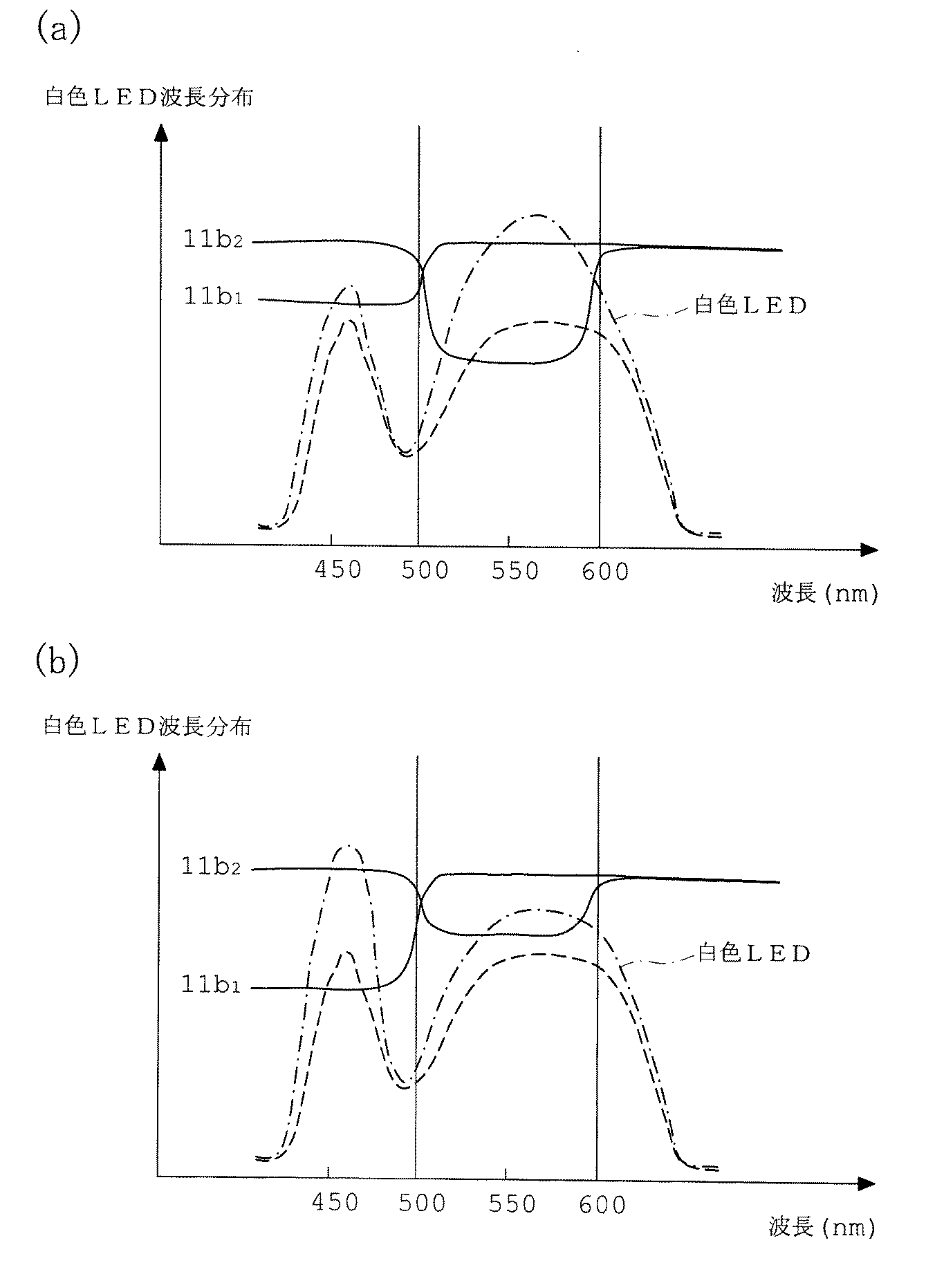
Table 1
また、実施例1にかかる照明光学系から波長分布変換素子が備えられていない構成の照明光学系(比較例1)と、実施例1にかかる波長分布変換素子を備えた照明光学系とにおける、従来のハロゲン光源とLBDフィルタとを組み合わせた照明光学系を基準としたときの相対演色評価数を次の表2に示す。
表2
Table 2
図5は本発明の実施例2にかかる照明光学系における白色LEDの強度分布と、波長分布変換素子の分光透過率特性と、それら白色LEDと波長分布変換素子とを組み合わせたときの分光強度分布とを示すグラフである。
なお、実施例2にかかる照明光学系の基本的な光学部材の構成は図1に示した構成とほぼ同じである。
FIG. 5 is an intensity distribution of a white LED, a spectral transmittance characteristic of a wavelength distribution conversion element, and a spectral intensity distribution when the white LED and the wavelength distribution conversion element are combined in an illumination optical system according to Example 2 of the present invention. It is a graph which shows.
The basic configuration of the optical member of the illumination optical system according to Example 2 is almost the same as the configuration shown in FIG.
また、従来のハロゲン光源とLBDフィルタとを組み合わせた照明光学系の色度座標と、実施例2にかかる照明光学系から波長分布変換素子が備えられていない構成の照明光学系(比較例2)の色度座標と、実施例2にかかる波長分布変換素子を備えた照明光学系の色度座標とを次の表3に示す。
表3
Table 3
また、実施例2にかかる照明光学系から波長分布変換素子が備えられていない構成の照明光学系(比較例2)と、実施例2にかかる波長分布変換素子を備えた照明光学系とにおける、従来のハロゲン光源とLBDフィルタとを組み合わせた照明光学系を基準としたときの相対演色評価数を次の表4に示す。
表4
Table 4
図6は本発明の実施例3にかかる照明光学系を用いた光学装置としての手術用顕微鏡の概略構成図である。
実施例3の手術用顕微鏡は、光源22を有する照明光学系20と、被検眼30を観察するための観察光学系40と、被検眼30と観察光学系40との間に配置されたハーフミラー50と、全反射ミラー51を備えている。
FIG. 6 is a schematic configuration diagram of a surgical microscope as an optical apparatus using an illumination optical system according to Example 3 of the present invention.
The surgical microscope of Example 3 includes an illumination
ハーフミラー50は、光源22から発せられた照明光束を観察光学系40の光軸40aに沿って被検眼30に照射するとともに、該被検眼30で反射した反射光束を前記光軸40aに沿って観察光学系40に導くものである。このハーフミラー50により、被検眼30の完全同軸照明が可能となり、被検眼30の眼底で反射した反射光束による徹照像(レッドレフレックス)を得ることができるようになっている。
The
全反射ミラー51は、被検眼30と観察光学系40との間、具体的には第1対物レンズ41の下方に配置されたハーフミラー50の下方において、被検眼30からの反射光束を遮らない位置(すなわち、手術医眼60が被検眼30を観察した際に、全反射ミラー51が手術医眼60の視野に入らない位置)に配置されている。
The
観察光学系40は、ハーフミラー50とほぼ同等な大きさに形成された第1対物レンズ41、任意の倍率を設定可能な変倍光学系42、第2対物レンズ43、正立プリズム44、菱形プリズム45、および、接眼レンズ46で構成されている。観察光学系40における、第1対物レンズ41以外の各光学素子は、手術医が両眼で立体的な観察を行えるよう、左右で一対になっており、図6においては、その片側のみが図示されている。
The observation
照明光学系20は、光源22のほか、光ファイバ23、コンデンサレンズ24及びリレーレンズ25で構成されている。
In addition to the
そして、このような構成を有する手術用顕微鏡においては、光源22から発せられた照明光束は、光ファイバ23、コンデンサレンズ24及びリレーレンズ25を経てハーフミラー50へと導かれる。ハ−フミラー50は、この照明光束を反射して、観察光学系40の光軸40aに沿って被検眼30に照射する。
一方、全反射ミラー51は、リレーレンズ25から射出された照明光束の一部を反射して、これを被検眼30に向けて照射する。全反射ミラー51の照射方向は、ハ−フミラー50の照射方向と僅かに異なっており、被検眼上の凹凸(例えば、白内障手術における、水晶体嚢内に残留している組織)による影をつくり出すことができるようになっている。また、ハーフミラー50の近傍に全反射ミラー51が配置されているために、ハーフミラー50の照射方向と全反射ミラー51の照射方向とが鋭角になり、影が間延びしないシャープな立体像を得ることができるようになっている。
被検眼30で反射した反射光束はハーフミラー50を通過し、観察光学系40に導かれる。この反射光束は観察光学系40を経て手術医眼60に到達するが、この際、反射光束による被検眼像は、変倍光学系42によって所定の倍率の拡大像となる。この拡大像は、第2対物レンズ43、正立プリズム44、および、菱形プリズム45を通過し、接眼レンズ46によって手術医眼60により観察されるようになっている。
In the surgical microscope having such a configuration, the illumination light beam emitted from the
On the other hand, the
The reflected light beam reflected by the
さらに、このような構成を備えた手術用顕微鏡において、光源22には、実施例1又は実施例2で示した波長特性を示す白色LEDが用いられている。また、実施例1又は実施例2において白色LEDに組み合わせた波長分布変換素子と同様の透過率特性を持つ波長分布変換素子21が、照明光学系20における光源22の出射光路上における所定の位置に配置されている。
Furthermore, in the surgical microscope having such a configuration, the
図7は本発明の実施例4にかかる照明光学系を用いた光学装置としての電子式内視鏡装置の概略構成図である。
実施例4の電子式内視鏡装置は電子式内視鏡70と画像プロセッサ80と光源装置90で構成されている。
FIG. 7 is a schematic configuration diagram of an electronic endoscope apparatus as an optical apparatus using an illumination optical system according to Example 4 of the present invention.
The electronic endoscope apparatus according to the fourth embodiment includes an
電子式内視鏡70は、操作部71と、挿入部72と、ケーブル73,74によって本体75を構成してなり、この本体75には内視鏡としての機能が組み込まれている。ケーブル73,74には画像プロセッサ80と光源装置90にそれぞれ接続されるコネクタ73a,74aが設けられている。
挿入部72の先端には対物結像用光学系76と固体撮像素子としてCCD77が設置されている。CCD77は本体75内に配設された信号線78を介して、コネクタ73aが接続される画像プロセッサ80に接続されるようになっている。
また、内視鏡70には挿入部72の先端まで照明光を伝達するガラスファイバ束であるライトガイド79が設けられている。ライトガイド79は、コネクタ74aを介して光源装置90に接続されるようになっている。
The
An objective imaging
The
光源装置90には照明光を発生する光源としてのランプ92と、この照明光をライトガイド79の入射端面に集光させるためのレンズ93が設置されている。
そして、実施例4の電子式内視鏡装置では、この光源装置90のランプ92と、レンズ93と、電子式内視鏡70のライトガイド79を有して照明光学系が構成されている。
The
The electronic endoscope apparatus according to the fourth embodiment includes the
画像プロセッサ80には内視鏡70のCCD77を駆動する駆動回路81と、CCD77が撮像した信号を処理する映像信号処理回路82と、駆動回路81の駆動を制御する制御回路83が設けられている。
The
このような構成の内視鏡装置において、光源装置90のランプ92には、実施例1又は実施例2で示した波長特性を示す白色LEDが用いられている。また、実施例1又は実施例2において白色LEDに組み合わせた波長分布変換素子と同様の透過率特性を持つ波長分布変換素子91が、照明光学系におけるランプ92の出射光路上における所定の位置(図7ではランプ92とレンズ93との間)に配置されている。
In the endoscope apparatus having such a configuration, a white LED having the wavelength characteristic shown in the first or second embodiment is used for the
本発明の白色光を発する固体発光素子を用いた照明光学系は、白色LEDを照明光源として用いて、被観察物体の色に基づいて被観察物体の状態を診断・検出等する病理診断分野等において有用である。 The illumination optical system using a solid-state light emitting element that emits white light according to the present invention uses a white LED as an illumination light source, and diagnoses and detects the state of the observed object based on the color of the observed object. Useful in.
1 ランプハウス
2 光源
3 コレクタレンズ
4 視野絞り
5 フィールドレンズ
6 開口絞り
7 コンデンサレンズ
8 被照明面(標本面)
9 LBDフィルタ
11 波長分布変換素子
11a 光学素子(フィルタ)
11b1 第1の光学素子
11b2 第2の光学素子
20 照明光学系
21 波長分布変換素子
22 光源
23 光ファイバ
24 コンデンサレンズ
25 リレーレンズ
30 被検眼
40 観察光学系
40a 光軸
41 第1対物レンズ
42 変倍光学系
43 第2対物レンズ
44 正立プリズム
45 菱形プリズム
46 接眼レンズ
50 ハーフミラー
51 全反射ミラー
60 手術医眼
70 電子式内視鏡
71 操作部
72 挿入部
73,74 ケーブル
73a,74a コネクタ
75 本体
76 対物結像用光学系
77 CCD
78 信号線
79 ライトガイド
80 画像プロセッサ
81 駆動回路
82 映像信号処理回路
83 制御回路
90 光源装置
91 波長分布変換素子
92 ランプ
93 レンズ
DESCRIPTION OF
9
11b 1 First optical element 11b 2 Second
78
Claims (9)
前記固体発光素子が発する白色光に内在する複数のピーク波長に対応して、前記各ピーク波長を含む所定波長領域ごとの透過率が段差を有して変化し、前記固体発光素子から発した白色光の波長分布を昼光色の波長分布に近似させる光学特性を持つ波長分布変換素子を、有することを特徴とする白色光を発する固体発光素子を用いた照明光学系。 In an illumination optical system using a solid light emitting element that emits white light,
Corresponding to a plurality of peak wavelengths inherent in white light emitted from the solid state light emitting device, the transmittance for each predetermined wavelength region including each peak wavelength changes with a step, and white light emitted from the solid state light emitting device An illumination optical system using a solid-state light emitting element that emits white light, including a wavelength distribution conversion element having optical characteristics that approximates a wavelength distribution of light to a daylight color wavelength distribution.
次の条件式(1)を満足する波長領域における所定波長値λ1を境として、透過率が変化し、前記所定波長値λ1よりも短い所定波長領域での透過率と、前記所定波長値λ1よりも長く前記所定波長値λ2よりも短い所定波長領域での透過率とが段差を有するとともに、次の条件式(2)を満足する波長領域における所定波長値λ2を境として、透過率が変化し、前記所定波長値λ1よりも長く前記所定波長値λ2よりも短い所定波長領域での透過率と、前記所定波長値λ2よりも長い所定波長領域での透過率とが段差を有し、前記固体発光素子から発した白色光の波長分布を昼光色の波長分布に近似させる光学特性を持つ波長分布変換素子を、有することを特徴とする白色光を発する固体発光素子を用いた照明光学系。
480nm≦λ1≦520nm …(1)
580nm≦λ2≦620nm …(2) In an illumination optical system using a solid light emitting element that emits white light,
From the predetermined wavelength value λ1 in the wavelength region satisfying the following conditional expression (1) as a boundary, the transmittance changes, and the transmittance in the predetermined wavelength region shorter than the predetermined wavelength value λ1 and the predetermined wavelength value λ1 The transmittance in the predetermined wavelength region that is longer than the predetermined wavelength value λ2 has a step, and the transmittance changes at the predetermined wavelength value λ2 in the wavelength region that satisfies the following conditional expression (2). The transmittance in a predetermined wavelength region longer than the predetermined wavelength value λ1 and shorter than the predetermined wavelength value λ2 and the transmittance in a predetermined wavelength region longer than the predetermined wavelength value λ2 have a step, and the solid An illumination optical system using a solid light-emitting element that emits white light, including a wavelength distribution conversion element having optical characteristics that approximates a wavelength distribution of white light emitted from a light-emitting element to a wavelength distribution of daylight color.
480 nm ≦ λ1 ≦ 520 nm (1)
580 nm ≦ λ2 ≦ 620 nm (2)
前記所定波長値λ1よりも短い所定波長領域での透過率が、前記所定波長値λ2よりも長い所定波長領域での透過率に比べて低く、且つ、
前記所定波長値λ1よりも長く前記所定波長領域λ2よりも短い所定波長領域での透過率が、前記所定波長値λ1よりも短い所定波長領域での透過率に比べて低くなるように構成された光学素子からなることを特徴とする請求項4に記載の白色光を発する固体発光素子を用いた照明光学系。 The wavelength distribution conversion element is:
The transmittance in a predetermined wavelength region shorter than the predetermined wavelength value λ1 is lower than the transmittance in a predetermined wavelength region longer than the predetermined wavelength value λ2, and
The transmittance in a predetermined wavelength region that is longer than the predetermined wavelength value λ1 and shorter than the predetermined wavelength region λ2 is lower than the transmittance in a predetermined wavelength region shorter than the predetermined wavelength value λ1. The illumination optical system using a solid-state light emitting element that emits white light according to claim 4, comprising an optical element.
前記所定波長値λ1よりも長く前記所定波長領域λ2よりも短い所定波長領域での透過率が、前記所定波長値λ1よりも短い所定波長領域での透過率に比べて高く、前記所定波長値λ2よりも長い所定波長領域での透過率に比べて低くなるように構成された光学素子からなることを特徴とする請求項4に記載の白色光を発する固体発光素子を用いた照明光学系。 The wavelength distribution conversion element is:
The transmittance in a predetermined wavelength region longer than the predetermined wavelength value λ1 and shorter than the predetermined wavelength region λ2 is higher than the transmittance in a predetermined wavelength region shorter than the predetermined wavelength value λ1, and the predetermined wavelength value λ2 5. An illumination optical system using a solid-state light-emitting element that emits white light according to claim 4, comprising an optical element configured to be lower than the transmittance in a longer predetermined wavelength region.
前記所定波長値λ1を境として、透過率が変化し、前記所定波長値λ1よりも短い所定波長領域での透過率と、前記所定波長値λ1よりも長い所定波長領域での透過率とが段差を有する第1の光学素子と、
前記所定波長値λ1を境として、透過率が変化し、前記所定波長値λ1よりも短い所定波長領域での透過率と、前記所定波長値λ1よりも長く前記所定波長値λ2よりも短い所定波長領域での透過率とが段差を有するとともに、前記所定波長値λ2を境として、透過率が変化し、前記所定波長値λ1よりも長く前記所定波長値λ2よりも短い所定波長領域での透過率と、前記所定波長値λ2よりも長い所定波長領域での透過率とが段差を有する第2の光学素子とを、
組み合わせてなることを特徴とする請求項4〜6のいずれかに記載の白色光を発する固体発光素子を用いた照明光学系。 The wavelength distribution conversion element is:
The transmittance changes with the predetermined wavelength value λ1 as a boundary, and the transmittance in a predetermined wavelength region shorter than the predetermined wavelength value λ1 and the transmittance in a predetermined wavelength region longer than the predetermined wavelength value λ1 are steps. A first optical element comprising:
The transmittance changes at the predetermined wavelength value λ1 as a boundary, the transmittance in a predetermined wavelength region shorter than the predetermined wavelength value λ1, and a predetermined wavelength longer than the predetermined wavelength value λ1 and shorter than the predetermined wavelength value λ2. The transmittance in a region has a level difference, the transmittance changes with the predetermined wavelength value λ2 as a boundary, and the transmittance in a predetermined wavelength region that is longer than the predetermined wavelength value λ1 and shorter than the predetermined wavelength value λ2 And a second optical element having a step difference in transmittance in a predetermined wavelength region longer than the predetermined wavelength value λ2.
An illumination optical system using a solid-state light emitting element that emits white light according to any one of claims 4 to 6, wherein the optical system is combined.
前記第2の光学素子は、前記所定波長値λ1よりも長く前記所定波長領域λ2よりも短い所定波長領域での透過率が、該所定波長値λ1よりも短い所定波長領域での透過率及び該所定波長値λ2よりも長い所定波長領域での透過率に比べて低くなるように構成されていることを特徴とする請求項7に記載の白色光を発する固体発光素子を用いた照明光学系。 The first optical element is configured such that a transmittance in a predetermined wavelength region shorter than the predetermined wavelength value λ1 is lower than a transmittance in a wavelength region longer than the predetermined wavelength value λ1, and ,
The second optical element has a transmittance in a predetermined wavelength region that is longer than the predetermined wavelength value λ1 and shorter than the predetermined wavelength region λ2, and in a predetermined wavelength region shorter than the predetermined wavelength value λ1. 8. The illumination optical system using a solid-state light emitting element that emits white light according to claim 7, wherein the illumination optical system is configured to be lower than the transmittance in a predetermined wavelength region longer than the predetermined wavelength value [lambda] 2.
Priority Applications (3)
| Application Number | Priority Date | Filing Date | Title |
|---|---|---|---|
| JP2006137776A JP2007311114A (en) | 2006-05-17 | 2006-05-17 | Lighting optical system using solid light emitting element emitting white light, and optical device equipped with it |
| US11/798,349 US7746560B2 (en) | 2006-05-17 | 2007-05-14 | Illumination optical system that uses a solid-state lighting element which generates white light, and an optical device equipped therewith |
| DE102007022666A DE102007022666A1 (en) | 2006-05-17 | 2007-05-15 | An optical illumination system having a solid state lighting element that produces white light, and optical device equipped therewith |
Applications Claiming Priority (1)
| Application Number | Priority Date | Filing Date | Title |
|---|---|---|---|
| JP2006137776A JP2007311114A (en) | 2006-05-17 | 2006-05-17 | Lighting optical system using solid light emitting element emitting white light, and optical device equipped with it |
Publications (1)
| Publication Number | Publication Date |
|---|---|
| JP2007311114A true JP2007311114A (en) | 2007-11-29 |
Family
ID=38711717
Family Applications (1)
| Application Number | Title | Priority Date | Filing Date |
|---|---|---|---|
| JP2006137776A Pending JP2007311114A (en) | 2006-05-17 | 2006-05-17 | Lighting optical system using solid light emitting element emitting white light, and optical device equipped with it |
Country Status (3)
| Country | Link |
|---|---|
| US (1) | US7746560B2 (en) |
| JP (1) | JP2007311114A (en) |
| DE (1) | DE102007022666A1 (en) |
Cited By (6)
| Publication number | Priority date | Publication date | Assignee | Title |
|---|---|---|---|---|
| JP2007333800A (en) * | 2006-06-12 | 2007-12-27 | Nikon Corp | Microscope illumination device and microscope device having the same |
| WO2010007810A1 (en) * | 2008-07-16 | 2010-01-21 | オリンパス株式会社 | Light source device, and endoscope apparatus having the device |
| JP2010087393A (en) * | 2008-10-02 | 2010-04-15 | Fujinon Corp | Light source device |
| JP2013029836A (en) * | 2011-07-27 | 2013-02-07 | Leica Microsystems Cms Gmbh | Microscope illumination method and microscope |
| US9207124B2 (en) | 2013-08-06 | 2015-12-08 | Seiko Epson Corporation | Colorimetry apparatus |
| JP2021064941A (en) * | 2018-11-30 | 2021-04-22 | ファスプロ システムズ カンパニー リミテッドFaspro Systems Co., Ltd | Photographing device |
Families Citing this family (18)
| Publication number | Priority date | Publication date | Assignee | Title |
|---|---|---|---|---|
| DE102006013761B4 (en) * | 2006-03-24 | 2016-12-15 | Carl Zeiss Meditec Ag | Lighting device and observation device |
| US7846391B2 (en) | 2006-05-22 | 2010-12-07 | Lumencor, Inc. | Bioanalytical instrumentation using a light source subsystem |
| JP5086580B2 (en) * | 2006-08-04 | 2012-11-28 | オリンパス株式会社 | Lighting device |
| US8098375B2 (en) | 2007-08-06 | 2012-01-17 | Lumencor, Inc. | Light emitting diode illumination system |
| US8177394B2 (en) * | 2008-11-07 | 2012-05-15 | Endure Medical, Inc. | Stereoscopic illumination system for microscope |
| DE102009057712A1 (en) * | 2008-12-18 | 2010-07-01 | Carl Zeiss Surgical Gmbh | Lighting device and observation device |
| US8523359B2 (en) * | 2008-12-18 | 2013-09-03 | Carl Zeiss Meditec Ag | Illumination device and observation device |
| US8242462B2 (en) | 2009-01-23 | 2012-08-14 | Lumencor, Inc. | Lighting design of high quality biomedical devices |
| US8389957B2 (en) | 2011-01-14 | 2013-03-05 | Lumencor, Inc. | System and method for metered dosage illumination in a bioanalysis or other system |
| US8466436B2 (en) | 2011-01-14 | 2013-06-18 | Lumencor, Inc. | System and method for metered dosage illumination in a bioanalysis or other system |
| DE102011079942B4 (en) | 2011-07-27 | 2016-12-15 | Leica Microsystems Cms Gmbh | Microscope illumination method and microscope |
| DE102011084574B4 (en) | 2011-10-14 | 2022-02-03 | Leica Microsystems Cms Gmbh | Illumination arrangement for a microscope |
| DE202011052474U1 (en) | 2011-12-23 | 2012-10-24 | Leica Microsystems (Schweiz) Ag | Microscope illumination device and microscope |
| US9103528B2 (en) | 2012-01-20 | 2015-08-11 | Lumencor, Inc | Solid state continuous white light source |
| US9217561B2 (en) | 2012-06-15 | 2015-12-22 | Lumencor, Inc. | Solid state light source for photocuring |
| WO2015131278A1 (en) * | 2014-03-04 | 2015-09-11 | Novadaq Technologies Inc. | Relay lens system for broadband imaging |
| US10809534B2 (en) | 2018-11-30 | 2020-10-20 | Faspro Systems Co., Ltd. | Photography device |
| WO2025257247A1 (en) | 2024-06-12 | 2025-12-18 | Roche Diagnostics International Ag | Automated pcr analyzer |
Citations (7)
| Publication number | Priority date | Publication date | Assignee | Title |
|---|---|---|---|---|
| WO2002091487A1 (en) * | 2001-05-02 | 2002-11-14 | Kansai Technology Licensing Organization Co., Ltd. | Light emitting apparatus |
| JP2002543453A (en) * | 1999-04-27 | 2002-12-17 | カール ツァイス イエナ ゲゼルシャフト ミット ベシュレンクテル ハフツング | Microscope illumination system using transmitted light |
| JP2004356116A (en) * | 2003-05-26 | 2004-12-16 | Citizen Electronics Co Ltd | Light emitting diode |
| JP2005063728A (en) * | 2003-08-08 | 2005-03-10 | Mitsubishi Chemicals Corp | Light emitting device, lighting device, and image display device |
| JP2005148296A (en) * | 2003-11-13 | 2005-06-09 | Olympus Corp | Light source apparatus of microscope |
| JP2005347263A (en) * | 2004-06-04 | 2005-12-15 | Lumileds Lighting Us Llc | Separate wavelength conversion in lighting systems |
| JP2006061685A (en) * | 2004-07-28 | 2006-03-09 | Kyocera Corp | Light source device and endoscope provided with the light source device |
Family Cites Families (1)
| Publication number | Priority date | Publication date | Assignee | Title |
|---|---|---|---|---|
| US7597447B2 (en) * | 2004-07-14 | 2009-10-06 | Honeywell International Inc. | Color correcting contrast enhancement of displays |
-
2006
- 2006-05-17 JP JP2006137776A patent/JP2007311114A/en active Pending
-
2007
- 2007-05-14 US US11/798,349 patent/US7746560B2/en active Active
- 2007-05-15 DE DE102007022666A patent/DE102007022666A1/en not_active Withdrawn
Patent Citations (7)
| Publication number | Priority date | Publication date | Assignee | Title |
|---|---|---|---|---|
| JP2002543453A (en) * | 1999-04-27 | 2002-12-17 | カール ツァイス イエナ ゲゼルシャフト ミット ベシュレンクテル ハフツング | Microscope illumination system using transmitted light |
| WO2002091487A1 (en) * | 2001-05-02 | 2002-11-14 | Kansai Technology Licensing Organization Co., Ltd. | Light emitting apparatus |
| JP2004356116A (en) * | 2003-05-26 | 2004-12-16 | Citizen Electronics Co Ltd | Light emitting diode |
| JP2005063728A (en) * | 2003-08-08 | 2005-03-10 | Mitsubishi Chemicals Corp | Light emitting device, lighting device, and image display device |
| JP2005148296A (en) * | 2003-11-13 | 2005-06-09 | Olympus Corp | Light source apparatus of microscope |
| JP2005347263A (en) * | 2004-06-04 | 2005-12-15 | Lumileds Lighting Us Llc | Separate wavelength conversion in lighting systems |
| JP2006061685A (en) * | 2004-07-28 | 2006-03-09 | Kyocera Corp | Light source device and endoscope provided with the light source device |
Cited By (6)
| Publication number | Priority date | Publication date | Assignee | Title |
|---|---|---|---|---|
| JP2007333800A (en) * | 2006-06-12 | 2007-12-27 | Nikon Corp | Microscope illumination device and microscope device having the same |
| WO2010007810A1 (en) * | 2008-07-16 | 2010-01-21 | オリンパス株式会社 | Light source device, and endoscope apparatus having the device |
| JP2010087393A (en) * | 2008-10-02 | 2010-04-15 | Fujinon Corp | Light source device |
| JP2013029836A (en) * | 2011-07-27 | 2013-02-07 | Leica Microsystems Cms Gmbh | Microscope illumination method and microscope |
| US9207124B2 (en) | 2013-08-06 | 2015-12-08 | Seiko Epson Corporation | Colorimetry apparatus |
| JP2021064941A (en) * | 2018-11-30 | 2021-04-22 | ファスプロ システムズ カンパニー リミテッドFaspro Systems Co., Ltd | Photographing device |
Also Published As
| Publication number | Publication date |
|---|---|
| DE102007022666A1 (en) | 2008-01-17 |
| US7746560B2 (en) | 2010-06-29 |
| US20070268575A1 (en) | 2007-11-22 |
Similar Documents
| Publication | Publication Date | Title |
|---|---|---|
| JP2007311114A (en) | Lighting optical system using solid light emitting element emitting white light, and optical device equipped with it | |
| JP4875319B2 (en) | Endoscope | |
| US8049184B2 (en) | Fluoroscopic device and fluoroscopic method | |
| JP5587120B2 (en) | Endoscope light source device | |
| CN109068968B (en) | Light source device for endoscope | |
| CN105136753B (en) | Filter system, fluorescence observation system and the method for executing fluorescence observation | |
| EP2404544A1 (en) | Endoscope apparatus | |
| KR20160037834A (en) | Medical imaging device and methods of use | |
| JP6924837B2 (en) | Medical image processing system, endoscopy system, diagnostic support device, and medical service support device | |
| JP2002065602A (en) | Illumination optical system and endoscope device | |
| US20190394371A1 (en) | Dual path endoscope | |
| JPWO2017061003A1 (en) | Endoscope device | |
| JPH04150845A (en) | Early cancer diagnosing apparatus | |
| JP7405080B2 (en) | Medical system, medical light source device, and operating method of medical light source device | |
| WO2018003263A1 (en) | Observation device and control method for observation device | |
| JPWO2019176253A1 (en) | Medical observation system | |
| JP5145119B2 (en) | Endoscope light source device | |
| JP2008259591A (en) | Light source device for fluorescence observation and fluorescence observation instrument using the same | |
| JP2005010296A (en) | Fluorescent microscope | |
| JP4184156B2 (en) | Endoscope device | |
| JP2001017380A (en) | Excitation light filter for fluorescent endoscope | |
| WO2025041695A1 (en) | Light source device and endoscope system | |
| JPH10314120A (en) | Fundus camera | |
| JP2022527642A (en) | Medical devices that utilize narrow-band imaging | |
| JP2006334245A (en) | Endoscope system |
Legal Events
| Date | Code | Title | Description |
|---|---|---|---|
| A621 | Written request for application examination |
Free format text: JAPANESE INTERMEDIATE CODE: A621 Effective date: 20090513 |
|
| A977 | Report on retrieval |
Free format text: JAPANESE INTERMEDIATE CODE: A971007 Effective date: 20101122 |
|
| A131 | Notification of reasons for refusal |
Free format text: JAPANESE INTERMEDIATE CODE: A131 Effective date: 20101130 |
|
| A02 | Decision of refusal |
Free format text: JAPANESE INTERMEDIATE CODE: A02 Effective date: 20110329 |