WO2000057460A1 - METHOD FOR GROWING GaN COMPOUND SEMICONDUCTOR CRYSTAL AND SEMICONDUCTOR SUBSTRATE - Google Patents
METHOD FOR GROWING GaN COMPOUND SEMICONDUCTOR CRYSTAL AND SEMICONDUCTOR SUBSTRATE Download PDFInfo
- Publication number
- WO2000057460A1 WO2000057460A1 PCT/JP2000/001718 JP0001718W WO0057460A1 WO 2000057460 A1 WO2000057460 A1 WO 2000057460A1 JP 0001718 W JP0001718 W JP 0001718W WO 0057460 A1 WO0057460 A1 WO 0057460A1
- Authority
- WO
- WIPO (PCT)
- Prior art keywords
- compound semiconductor
- gan
- substrate
- based compound
- crystal
- Prior art date
- Legal status (The legal status is an assumption and is not a legal conclusion. Google has not performed a legal analysis and makes no representation as to the accuracy of the status listed.)
- Ceased
Links
Classifications
-
- C—CHEMISTRY; METALLURGY
- C30—CRYSTAL GROWTH
- C30B—SINGLE-CRYSTAL GROWTH; UNIDIRECTIONAL SOLIDIFICATION OF EUTECTIC MATERIAL OR UNIDIRECTIONAL DEMIXING OF EUTECTOID MATERIAL; REFINING BY ZONE-MELTING OF MATERIAL; PRODUCTION OF A HOMOGENEOUS POLYCRYSTALLINE MATERIAL WITH DEFINED STRUCTURE; SINGLE CRYSTALS OR HOMOGENEOUS POLYCRYSTALLINE MATERIAL WITH DEFINED STRUCTURE; AFTER-TREATMENT OF SINGLE CRYSTALS OR A HOMOGENEOUS POLYCRYSTALLINE MATERIAL WITH DEFINED STRUCTURE; APPARATUS THEREFOR
- C30B25/00—Single-crystal growth by chemical reaction of reactive gases, e.g. chemical vapour-deposition growth
- C30B25/02—Epitaxial-layer growth
- C30B25/18—Epitaxial-layer growth characterised by the substrate
-
- C—CHEMISTRY; METALLURGY
- C30—CRYSTAL GROWTH
- C30B—SINGLE-CRYSTAL GROWTH; UNIDIRECTIONAL SOLIDIFICATION OF EUTECTIC MATERIAL OR UNIDIRECTIONAL DEMIXING OF EUTECTOID MATERIAL; REFINING BY ZONE-MELTING OF MATERIAL; PRODUCTION OF A HOMOGENEOUS POLYCRYSTALLINE MATERIAL WITH DEFINED STRUCTURE; SINGLE CRYSTALS OR HOMOGENEOUS POLYCRYSTALLINE MATERIAL WITH DEFINED STRUCTURE; AFTER-TREATMENT OF SINGLE CRYSTALS OR A HOMOGENEOUS POLYCRYSTALLINE MATERIAL WITH DEFINED STRUCTURE; APPARATUS THEREFOR
- C30B29/00—Single crystals or homogeneous polycrystalline material with defined structure characterised by the material or by their shape
- C30B29/10—Inorganic compounds or compositions
- C30B29/40—AIIIBV compounds wherein A is B, Al, Ga, In or Tl and B is N, P, As, Sb or Bi
- C30B29/403—AIII-nitrides
- C30B29/406—Gallium nitride
-
- H—ELECTRICITY
- H10—SEMICONDUCTOR DEVICES; ELECTRIC SOLID-STATE DEVICES NOT OTHERWISE PROVIDED FOR
- H10H—INORGANIC LIGHT-EMITTING SEMICONDUCTOR DEVICES HAVING POTENTIAL BARRIERS
- H10H20/00—Individual inorganic light-emitting semiconductor devices having potential barriers, e.g. light-emitting diodes [LED]
- H10H20/01—Manufacture or treatment
- H10H20/011—Manufacture or treatment of bodies, e.g. forming semiconductor layers
- H10H20/013—Manufacture or treatment of bodies, e.g. forming semiconductor layers having light-emitting regions comprising only Group III-V materials
- H10H20/0133—Manufacture or treatment of bodies, e.g. forming semiconductor layers having light-emitting regions comprising only Group III-V materials with a substrate not being Group III-V materials
- H10H20/01335—Manufacture or treatment of bodies, e.g. forming semiconductor layers having light-emitting regions comprising only Group III-V materials with a substrate not being Group III-V materials the light-emitting regions comprising nitride materials
-
- H—ELECTRICITY
- H10—SEMICONDUCTOR DEVICES; ELECTRIC SOLID-STATE DEVICES NOT OTHERWISE PROVIDED FOR
- H10H—INORGANIC LIGHT-EMITTING SEMICONDUCTOR DEVICES HAVING POTENTIAL BARRIERS
- H10H20/00—Individual inorganic light-emitting semiconductor devices having potential barriers, e.g. light-emitting diodes [LED]
- H10H20/01—Manufacture or treatment
- H10H20/011—Manufacture or treatment of bodies, e.g. forming semiconductor layers
- H10H20/013—Manufacture or treatment of bodies, e.g. forming semiconductor layers having light-emitting regions comprising only Group III-V materials
- H10H20/0137—Manufacture or treatment of bodies, e.g. forming semiconductor layers having light-emitting regions comprising only Group III-V materials the light-emitting regions comprising nitride materials
-
- H10P14/24—
-
- H10P14/272—
-
- H10P14/2901—
-
- H10P14/2921—
-
- H10P14/3216—
-
- H10P14/3416—
-
- H10P14/36—
Definitions
- the present invention relates to a method for growing a GaN-based compound semiconductor crystal, and a semiconductor substrate using the crystal.
- Epitaxial growth of GaN-based compound semiconductor crystals is generally performed on a sapphire substrate or the like via a buffer layer because it is difficult to obtain a lattice-matched substrate.
- lattice defects such as dislocations are introduced from the growth interface, and dislocations on the order of about 1 O ⁇ cm— 2 exist on the surface of the epitaxial film.
- Dislocations in the epitaxial film cause leakage current, non-light-emitting centers, and diffusion of electrode materials in the device. Therefore, a method of reducing the dislocation density has been attempted.
- the invention thus provides, in a Epitakisharu growth of G a N-based compound semiconductor crystal, with reduced dislocation density without using a mask material such as S i 0 2 used in a conventional selective growth, high quality Epitakisharu
- the purpose is to provide.
- the semiconductor substrate of the present invention is a semiconductor substrate in which a GaN-based compound semiconductor crystal is grown on a substrate, wherein the semiconductor crystal comprises a layer having a high dislocation density, and a layer adjacent to the layer having a relatively high dislocation density. A low-density layer, and an interface or region where the anti-surfactant material is immobilized exists between the two layers.
- Another semiconductor substrate of the present invention is characterized in that an interface or a region where an anti-surfactant material is immobilized is provided immediately above a substrate, and a GaN-based compound semiconductor crystal is grown thereon. .
- the anti-surfactant material is Si.
- two or more layers composed of the interface or region where the anti-surfactant material is immobilized and the GaN-based compound semiconductor crystal grown thereon are designed to be multiplexed. Even good ,.
- the substrate state is changed by changing the surface state of the substrate with an anti-fatatant material, and the GaN-based compound semiconductor material is supplied by a vapor phase growth method.
- a dot structure composed of a GaN compound semiconductor is formed on the surface, and growth continues until the dot structures are united and the surface becomes flat. It is characterized by having a process.
- the surface state is changed by an anti-surfactant material.
- a dot structure composed of a GaN-based compound semiconductor is formed on the surface of the GaN-based compound semiconductor film, the dot structures are united, and the surface is formed. It is characterized by having a step of continuing growth until it becomes flat.
- FIG. 1 is a schematic view showing a step of growing a GaN-based compound semiconductor crystal of the present invention.
- FIG. 2 is a schematic view showing a cross section of a GaN-based compound semiconductor substrate produced by the growth method of the present invention.
- FIG. 3 is an enlarged sectional view of a main part of FIG.
- 11 is a substrate
- 12 is a GaN-based compound semiconductor crystal
- 14 is a dot structure
- 21 is a cavity
- 22 is a dislocation line
- 3 is an anti-phosphatatant material
- S is an anti-antagonist. The interface where the factorant material was immobilized is shown.
- the surface state is modified.
- the anti-surfactant material is immobilized on the modified surface, and the present inventor has found that the immobilized anti-surfactant material functions to prevent dislocation lines from extending. Found them.
- the anti-surfactant material acts like a mask material in the prior art, the crystal growth starts only from the part where the anti-surfactant material is not fixed, and if the growth is continued, the lateral growth By the action, the anti-surfactant material is embedded. Therefore, a layer located above the interface where the anti-surfactant material is fixed becomes a high-quality semiconductor layer with reduced dislocation defects.
- the anti-surfactant material is immobilized directly on the substrate, the occurrence of dislocation defects itself is suppressed, and thus a high-quality semiconductor Layers can be formed.
- a GaN-based compound semiconductor 12 is grown on the substrate 11 in advance, and a substance (anti-surfactant material) 3 that changes the surface state is allowed to act on the surface (FIG. 1 (a)).
- the substrate can be sapphire, SiC, GaN, Si, ZnO, spinel, or the like.
- the anti-surfactant material may be brought into contact.
- the method of contact is not limited.
- TES i Te Toraechirushiran
- a method can be mentioned for supplying a compound containing S i and silane (S i H 4) as the gas-like.
- the anti-surfactant material By applying the anti-surfactant material to the surface, many small regions with high surface energy are present on the surface. That is, the antisurfactant material is immobilized on the substrate surface. Thereafter, when the GaN-based compound semiconductor material is continuously supplied, the GaN-based compound semiconductor is unlikely to grow from a region having a high surface energy, and a dot structure 14 is formed (FIG. 1 (b)).
- This phenomenon can be interpreted as that the anti-surfactant material is immobilized on the substrate by adsorption or chemical bonding, covers the crystal surface, and inhibits the two-dimensional growth of the GaN-based crystal. That is, though derconnection Acting as S i 0 2 mask used for selective growth, such effects, G e, M g, can be obtained by Anchisa one Fatatanto material such as Z n. However, it is desirable to use Si in that it avoids the problem of crystal contamination.
- the dot structure in the present invention refers to a microstructure generated from a region where the anti-surfactant material does not act or a region which does not inhibit the growth of GaN, and has a multi-sided structure, a dome shape, a rod shape, or the like. It takes on various forms, depending on the crystal growth conditions, the crystallinity of the base, the distribution density of the anti-surfactant material, etc. Will be different.
- the density of the region where the anti-surfactant material acts can be controlled by the supply amount, the supply time, or the substrate temperature of the anti-surfactant material.
- the dot structures begin to coalesce (Fig. 1 (c)). At this time, the dot structures coalesce while forming a cavity 21 above the antisurfactant region (Fig. 2). Since the dot structure is formed by epitaxy growth from the minute opening region, the probability of dislocation lines extending through this opening is extremely low, and dislocation lines 22 extending from the base are blocked by this cavity. The dislocation density on the surface of the epitaxial film is reduced.
- FIG. 3 is an enlarged cross-sectional view of a main part of FIG. 2, and the above points will be described in further detail.
- the anti-surfactant material 3 is fixed at the atomic level on the surface of the GaN-based compound semiconductor 12 into which the anti-surfactant material has been introduced.
- the dot structure 14 is generated in the non-fixed portion as described above.
- each dot grows in the lateral direction at a rate of 14 kala, and the growth of the adjacent dots is united, and the crystal grows in the thickness direction.
- the growth layer E stacked thereon can be a high-quality layer with reduced dislocation density. That is, a semiconductor layer having a low dislocation density can be formed via the interface S on which the anti-surfactant material 3 is fixed.
- the cavity 21 has a force or an atomic arrangement that is a void in the order of several atomic layers. Many discontinuous lines are observed.
- the rate of reduction of dislocations due to the interface also depends on the degree of surface modification with the anti-surfactant material, but generally can be reduced by 90% or more.
- the G a N grown thereon.
- S i 0 does not use a mask material such as 2, also very long lateral growth required before small Dots structure is grown thin to coalesce Since the crystal is short and its time is very small, the crystal axis (C axis) does not tilt when the crystal grows in the upper part of the cavity 21, so that no new defects are generated. Les ,.
- one of the features of the GaN-based semiconductor is a column structure.
- Each column structure has not only the fluctuation of the C axis described above but also fluctuation in the direction of rotating the C axis.
- the fluctuation in the C-axis can be suppressed, but the fluctuation in the rotation direction can also be suppressed. Therefore, the effect of reducing dislocations by lateral growth is extremely large as compared with the case where a mask material is used.
- a G a ⁇ -based compound semiconductor is grown on a substrate in advance, and an anti-surfactant material is applied to the surface of the compound semiconductor.
- the anti-surfactant material is directly applied to the surface of the substrate. It does not matter.
- the anti-surfactant material 13 is applied directly on the substrate 11 without performing the step of growing the GaN-based compound semiconductor 12 on the substrate 11 in advance. Can obtain a semiconductor substrate in the same manner as described above.
- the GaN-based compound semiconductor crystal grown on the substrate by this method becomes a high-quality crystal layer with a low dislocation density.
- the sapphire C-plane substrate was set in a M ⁇ C VD apparatus, and the temperature was increased to 1,200 ° C in a hydrogen atmosphere, and thermal etching was performed. Thereafter, the temperature was lowered to 500 ° C, and trimethylaluminum (hereinafter referred to as TMA) as an A1 material and ammonia as an N material were flown to grow an A1N low-temperature buffer layer to 30 nm.
- TMA trimethylaluminum
- TMG trimethylgallium
- ammonia as a N raw material
- GaN semiconductor crystal obtained in Example 1 above As a substrate, supplying tetraethylsilane as a source of an anti-surfactant material in the same manner as described above, and then repeating the step of crystal growth.
- a GaN semiconductor crystal was created by multiplexing five interfaces where the material was immobilized.
- the fifth on the interface was measured dislocation density of the grown G a N semiconductor crystal layer was reduced to 10 2 cm- 2.
- the dislocation density using G a N substrate of 10 5 cm one 2 the substrate MO
- the sample was set in a CVD apparatus, heated to 110 ° C in a hydrogen atmosphere (at 700 ° C or more, ammonia was also flown simultaneously), and thermal etching was performed. Thereafter, the temperature was lowered to 1050 ° C., and TMG as a Ga raw material and ammonia as an N raw material were flowed to grow GaN to 2 ⁇ m. Next, the supply of the raw material gas was stopped, the growth temperature was maintained, silane (SH 4 ) as an anti-surfactant material was supplied using H 2 as a carrier gas, and the GaN surface was contacted for 15 seconds.
- silane (SH 4 ) silane as an anti-surfactant material was supplied using H 2 as a carrier gas
- PIN photodiodes were manufactured.
- the device structure was manufactured by sequentially growing the following structure on the GaN substrate manufactured in each example from the fifth layer side.
- the size of the element was 5 mm ⁇ 5 mm.
- the conventional structure was fabricated on a sapphire substrate. The dislocation density at this time is estimated to 1 0 9 cm- 2.
- Example 5 As in Example 4, a light emitting device structure was sequentially grown on the GaN substrate produced by the method of Examples 1 to 3, and an ultraviolet LED having an emission wavelength of 375 nm was produced.
- the light-emitting device section has an SQW structure with exactly the same structure for all three types.
- the dislocation density can be reduced without using a mask material. This makes it possible to produce high-quality GaN-based compound semiconductor crystals. If semiconductor light-emitting devices such as LEDs and LDs, light-receiving devices, and electronic devices are fabricated on top of them, their characteristics are expected to be dramatically improved.
- an anti-surfactant material by applying an anti-surfactant material, an effect substantially equivalent to selective growth can be obtained without patterning or the like, so that the process from the anti-surfactant treatment to the growth of the semiconductor layer can be continuously performed in the growth apparatus.
- the manufacturing process is simplified.
Landscapes
- Chemical & Material Sciences (AREA)
- Engineering & Computer Science (AREA)
- Crystallography & Structural Chemistry (AREA)
- Materials Engineering (AREA)
- Metallurgy (AREA)
- Organic Chemistry (AREA)
- Chemical Kinetics & Catalysis (AREA)
- General Chemical & Material Sciences (AREA)
- Inorganic Chemistry (AREA)
- Led Devices (AREA)
- Semiconductor Lasers (AREA)
- Crystals, And After-Treatments Of Crystals (AREA)
Abstract
Description
明 細 書 Specification
G a N系化合物半導体結晶の成長方法及び半導体基材 Method for growing GaN-based compound semiconductor crystal and semiconductor substrate
技術分野 Technical field
本発明は、 G a N系化合物半導体結晶の成長方法、 及び該結晶を用いた半導体 基材に関するものである。 The present invention relates to a method for growing a GaN-based compound semiconductor crystal, and a semiconductor substrate using the crystal.
背景技術 Background art
G a N系化合物半導体結晶のェピタキシャル成長は、 格子整合する基板の入手 が困難であるため、 一般にサファィァ基板などの上にバッファ層を介して行われ ている。 この場合、 ェピタキシャル膜と基板との格子不整合のため、 成長界面か ら転位などの格子欠陥が導入され、 ェピタキシャル膜の表面には約 1 O ^ c m— 2オーダーの転位が存在する。 前記ェピタキシャル膜中の転位は、 デバイスにお いてリーク電流、 非発光センターや電極材料の拡散の原因となるため、 転位密度 を減らす方法が試みられている。 Epitaxial growth of GaN-based compound semiconductor crystals is generally performed on a sapphire substrate or the like via a buffer layer because it is difficult to obtain a lattice-matched substrate. In this case, due to lattice mismatch between the epitaxial film and the substrate, lattice defects such as dislocations are introduced from the growth interface, and dislocations on the order of about 1 O ^ cm— 2 exist on the surface of the epitaxial film. Dislocations in the epitaxial film cause leakage current, non-light-emitting centers, and diffusion of electrode materials in the device. Therefore, a method of reducing the dislocation density has been attempted.
その一つとして、 例えば特開平 1 0— 3 1 2 9 7 1号公報に記載されているよ うな、 選択成長を用いた方法がある。 この方法は、 S i 0 2などのマスク材料を 用いて基板上にパターユングを施与して選択成長を行い、 さらにこのマスク材料 を埋め込むまで成長を続けることで、 マスク材料により転位が遮断され、 或いは マスク上における結晶成長過程で転位の伝搬方向が曲げられるなどの効果により 、 転位密度の低減がなされるものである。 As one of the methods, there is a method using selective growth as described in, for example, Japanese Patent Application Laid-Open No. 10-31,971. This method performs a selective growth by application of the putter Jung on a substrate using a mask material such as S i 0 2, by continuing the growth until further embed the mask material, dislocations are blocked by the mask material Alternatively, the dislocation density is reduced by the effect of bending the dislocation propagation direction during the crystal growth process on the mask.
しかしながら上記の方法では、 マスク材料を埋め込む際に、 マスク上を成長面 に対して横方向に成長した結晶が、 成長が進むにつれその結晶軸が傾くチルト ( Tilt) という現象がおこる。 マスク上ではチルトした結晶同士が合体するのでそ こで新たな欠陥が発生する。 結晶軸がチルトする原因は定かではないが、 マスク 材料が影響しているものと考えられる。 また、 マスクを作製する工程はェピタキ シャル結晶成長装置から一旦外部に取り出してから行う必要があるため、 工程の 複雑化、 基板の汚染、 又は基板表面が損傷を受ける可能性がある等の問題を有し ている。 近年、 ハライ ド気相ェピタキシャル法 (H V P E ) 等を使って高品質の G a N 基板が得られる様になつてきてはいる。 しかし、 それでも 1 0 5〜 1 0 7 c m— 2 の転位密度の基板であり、 デバイスの高性能化には更に転位密度を下げることが 要求され、 また不可欠でもある。 However, in the above method, when the mask material is buried, a crystal that grows on the mask in the lateral direction with respect to the growth surface causes a phenomenon in which the crystal axis is tilted as the growth proceeds. On the mask, the tilted crystals coalesce, which causes new defects. The cause of the tilt of the crystal axis is not clear, but it is considered that the mask material has an effect. In addition, since the process of fabricating the mask must be performed once after being taken out of the epitaxial crystal growth apparatus, problems such as the complexity of the process, contamination of the substrate, and the possibility of damaging the substrate surface are raised. Yes. In recent years, high quality GaN substrates have been obtained using the halide vapor phase epitaxy (HVPE) method. However, still a board of 1 0 5 ~ 1 0 7 cm- 2 dislocation density, is required to further reduce the dislocation density in high-performance devices, there are also essential.
従って本発明は、 G a N系化合物半導体結晶のェピタキシャル成長において、 従来の選択成長に用いられる S i 0 2などのマスク材料を用いること無しに転位 密度を低減させた、 高品質なェピタキシャル膜を備える半導体基材及び成長方法 を提供することを目的とし、 特に、 比較的高品質な G a N基板を、 更に転位密度 を低減させ、 より高品質なェピタキシャル膜を得るための成長方法を提供するこ とを目的とする。 The invention thus provides, in a Epitakisharu growth of G a N-based compound semiconductor crystal, with reduced dislocation density without using a mask material such as S i 0 2 used in a conventional selective growth, high quality Epitakisharu In particular, it is an object of the present invention to provide a semiconductor substrate having a film and a growth method, particularly a relatively high-quality GaN substrate, a growth method for further reducing dislocation density and obtaining a higher-quality epitaxy film. The purpose is to provide.
発明の開示 Disclosure of the invention
本発明の半導体基材は、 基板上に G a N系化合物半導体結晶が成長された半導 体基材において、 前記半導体結晶は、 転位密度が大なる層と、 これに隣接し相対 的に転位密度が小なる層とを有し、 これら両層の間にはアンチサ一ファクタント 材料が固定化された界面又は領域が存在していることを特徴とする。 The semiconductor substrate of the present invention is a semiconductor substrate in which a GaN-based compound semiconductor crystal is grown on a substrate, wherein the semiconductor crystal comprises a layer having a high dislocation density, and a layer adjacent to the layer having a relatively high dislocation density. A low-density layer, and an interface or region where the anti-surfactant material is immobilized exists between the two layers.
本発明の他の半導体基材は、 基板直上にアンチサーファクタント材料が固定化 された界面又は領域を設け、 その上に G a N系化合物半導体結晶が成長されてい ることを特徴とするものである。 Another semiconductor substrate of the present invention is characterized in that an interface or a region where an anti-surfactant material is immobilized is provided immediately above a substrate, and a GaN-based compound semiconductor crystal is grown thereon. .
これらの場合において、 アンチサ一ファタタント材料が、 S iであることが好 ましい。 In these cases, it is preferred that the anti-surfactant material is Si.
さらに、 上記の場合において、 アンチサ一ファタタント材料が固定化された界 面又は領域と、 その上に成長される G a N系化合物半導体結晶とからなる層が、 2層以上多重化されるようにしても良レ、。 Furthermore, in the above case, two or more layers composed of the interface or region where the anti-surfactant material is immobilized and the GaN-based compound semiconductor crystal grown thereon are designed to be multiplexed. Even good ,.
また本発明の G a N系化合物半導体結晶の成長方法は、 基板の表面状態をアン チサ一ファタタント材料により変化させ、 G a N系化合物半導体材料を気相成長 法にて供給することによって、 基板表面に G a N系化合物半導体からなるドット 構造を形成し、 ドット構造同士が合体し、 表面が平坦になるまで成長を続けるェ 程を有することを特徴とする。 Further, in the method of growing a GaN-based compound semiconductor crystal of the present invention, the substrate state is changed by changing the surface state of the substrate with an anti-fatatant material, and the GaN-based compound semiconductor material is supplied by a vapor phase growth method. A dot structure composed of a GaN compound semiconductor is formed on the surface, and growth continues until the dot structures are united and the surface becomes flat. It is characterized by having a process.
さらに本発明の G a N系化合物半導体結晶の成長方法は、 前記基板表面に G a N系化合物半導体膜を形成した後、 その表面状態をアンチサ一ファタタント材料 により変化させ、 G a N系化合物半導体材料を気相成長法にて供給することによ つて、 前記 G a N系化合物半導体膜表面に G a N系化合物半導体からなる ドッ ト 構造を形成し、 ドッ ト構造同士が合体し、 表面が平坦になるまで成長を続けるェ 程を有することを特徴とする。 Further, in the method for growing a GaN-based compound semiconductor crystal of the present invention, after forming a GaN-based compound semiconductor film on the substrate surface, the surface state is changed by an anti-surfactant material, By supplying the material by vapor phase epitaxy, a dot structure composed of a GaN-based compound semiconductor is formed on the surface of the GaN-based compound semiconductor film, the dot structures are united, and the surface is formed. It is characterized by having a step of continuing growth until it becomes flat.
図面の簡単な説明 BRIEF DESCRIPTION OF THE FIGURES
図 1は、 本発明の G a N系化合物半導体結晶の成長工程を示す概略図である。 図 2は、 本発明の成長方法により作製した G a N系化合物半導体基材の断面を 示す概略図である。 FIG. 1 is a schematic view showing a step of growing a GaN-based compound semiconductor crystal of the present invention. FIG. 2 is a schematic view showing a cross section of a GaN-based compound semiconductor substrate produced by the growth method of the present invention.
図 3は、 図 2の要部拡大断面図である。 FIG. 3 is an enlarged sectional view of a main part of FIG.
各図において、 1 1は基板、 1 2は G a N系化合物半導体結晶、 1 4はドッ ト 構造、 2 1は空洞、 2 2は転位線、 3はアンチサ一ファタタント材料、 Sはアン チサ一ファクタント材料が固定化された界面を示している。 In each figure, 11 is a substrate, 12 is a GaN-based compound semiconductor crystal, 14 is a dot structure, 21 is a cavity, 22 is a dislocation line, 3 is an anti-phosphatatant material, and S is an anti-antagonist. The interface where the factorant material was immobilized is shown.
発明の詳細な説明 Detailed description of the invention
G a N系化合物半導体結晶に対して、 アンチサ一ファクタント材料を供給する ことによって、 その表面状態が改質される。 この改質された表面には、 アンチサ 一ファクタント材料が固定化されることになるのであるが、 当該固定化されたァ ンチサーファクタント材料が転位線の延伸を阻止する作用をなすことを本発明者 らは見出した。 すなわち、 アンチサ一ファタタント材料が従来技術でいうマスク 材の如き働きをなし、 アンチサ一ファタタント材料が固定化されていなレ、部分か らのみ結晶成長が始まり、 成長が継続されるとラテラル方向の成長作用によって アンチサ一ファタタント材料が埋め込まれることになる。 したがって、 アンチサ 一ファクタント材料が固定化された界面より上方に位置する層は、 転位欠陥が低 減された高品質の半導体層となる。 なお、 基板直上にアンチサ一ファクタント材 料を固定化した場合は、 転位欠陥の発生自体が抑制され、 而して高品質の半導体 層が形成できる。 By supplying an anti-surfactant material to the GaN-based compound semiconductor crystal, the surface state is modified. The anti-surfactant material is immobilized on the modified surface, and the present inventor has found that the immobilized anti-surfactant material functions to prevent dislocation lines from extending. Found them. In other words, the anti-surfactant material acts like a mask material in the prior art, the crystal growth starts only from the part where the anti-surfactant material is not fixed, and if the growth is continued, the lateral growth By the action, the anti-surfactant material is embedded. Therefore, a layer located above the interface where the anti-surfactant material is fixed becomes a high-quality semiconductor layer with reduced dislocation defects. When the anti-surfactant material is immobilized directly on the substrate, the occurrence of dislocation defects itself is suppressed, and thus a high-quality semiconductor Layers can be formed.
以下本発明の実施態様につき、 図 1、 図 2を用いて説明する。 Hereinafter, embodiments of the present invention will be described with reference to FIGS.
まず基板 1 1上に G a N系化合物半導体 1 2を予め成長しておき、 その表面に 表面状態を変化させる物質 (アンチサ一ファタタント材料) 3を作用させる (図 1 ( a ) ) 。 ここで基板はサファイア、 S i C、 G a N、 S i、 Z n O、 スピネ ル等を用いることができる。 表面にアンチサ一ファクタント材料を作用させるに は、 表面とアンチサ一ファタタント材料を接触させればよい。 接触の方法は限定 されないが、 例えば有機金属気相成長法 (M O C V D法) を用いる場合であれば 、 M O C V D装置内で基板上に G a N系化合物半導体を成長した後、 装置内にァ ンチサ一ファタタント材料を供給すればよい。 その供給方法としては、 例えばテ トラェチルシラン (T E S i ) 、 シラン (S i H 4) 等の S i を含む化合物をガ ス状として供給する方法が挙げられる。 First, a GaN-based compound semiconductor 12 is grown on the substrate 11 in advance, and a substance (anti-surfactant material) 3 that changes the surface state is allowed to act on the surface (FIG. 1 (a)). Here, the substrate can be sapphire, SiC, GaN, Si, ZnO, spinel, or the like. In order for the anti-surfactant material to act on the surface, the surface and the anti-surfactant material may be brought into contact. The method of contact is not limited. For example, when a metal organic chemical vapor deposition (MOCVD) method is used, a GaN-based compound semiconductor is grown on a substrate in a MOCVD apparatus, and then an antenna is formed in the apparatus. What is necessary is just to supply a fatathant material. As the supply method, for example, Te Toraechirushiran (TES i), a method can be mentioned for supplying a compound containing S i and silane (S i H 4) as the gas-like.
アンチサ一ファクタント材料を表面に作用させることにより、 表面エネルギー が高い、 微小な領域が表面に多数存在するようになる。 すなわち、 アンチサーフ ァクタント材料が基板表面に固定化されることになる。 その後連続して G a N系 化合物半導体材料を供給すると、 表面エネルギーの高い領域からは G a N系化合 物半導体は成長しにくく、 ドット構造 1 4が形成される (図 1 ( b ) ) 。 By applying the anti-surfactant material to the surface, many small regions with high surface energy are present on the surface. That is, the antisurfactant material is immobilized on the substrate surface. Thereafter, when the GaN-based compound semiconductor material is continuously supplied, the GaN-based compound semiconductor is unlikely to grow from a region having a high surface energy, and a dot structure 14 is formed (FIG. 1 (b)).
この現象は、 アンチサ一ファクタント材料が基板上に吸着又は化学結合により 固定化されて結晶表面を覆い、 G a N系結晶の二次元成長を阻害するとも解釈さ れる。 即ち、 あたかも選択成長に用いる S i 0 2マスクの如く作用するものであ つて、 このような作用は、 G e、 M g、 Z n等のアンチサ一ファタタント材料で も得られる。 しかしながら、 結晶の汚染の問題を回避するという点において、 S iを用いることが望ましい。 This phenomenon can be interpreted as that the anti-surfactant material is immobilized on the substrate by adsorption or chemical bonding, covers the crystal surface, and inhibits the two-dimensional growth of the GaN-based crystal. That is, though der connexion Acting as S i 0 2 mask used for selective growth, such effects, G e, M g, can be obtained by Anchisa one Fatatanto material such as Z n. However, it is desirable to use Si in that it avoids the problem of crystal contamination.
本発明におけるドット構造とは、 アンチサ一ファタタント材料が作用していな い領域、 或いは G a Nの成長を阻害しない領域から発生する微小構造体を指し、 その形状は多面構造、 ドーム状、 棒状など、 様々な形態を呈し、 かかる形態は結 晶成長条件、 下地の結晶性、 アンチサ一ファクタント材料の分布密度などにより 異なることになる。 The dot structure in the present invention refers to a microstructure generated from a region where the anti-surfactant material does not act or a region which does not inhibit the growth of GaN, and has a multi-sided structure, a dome shape, a rod shape, or the like. It takes on various forms, depending on the crystal growth conditions, the crystallinity of the base, the distribution density of the anti-surfactant material, etc. Will be different.
アンチサ一ファクタント材料が作用する領域の密度は、 アンチサ一ファクタン ト材料の供給量、 供給時間または基板の温度などにより制御できる。 The density of the region where the anti-surfactant material acts can be controlled by the supply amount, the supply time, or the substrate temperature of the anti-surfactant material.
ドット構造が形成されたあと、 さらに連続して G a N系化合物半導体の成長を 行うと、 ドッ ト構造同士は合体し始める (図 1 ( c ) ) 。 この時アンチサーファ クタント領域の上部に空洞 2 1を形成しながら、 ドット構造は合体する (図 2 ) 。 ドッ ト構造は微小開口領域からのェピタキシャル成長によって形成されるため 、 転位線がこの開口を通して延伸する確率は極めて低くなり、 また下地から伸び た転位線 2 2はこの空洞部で遮断されるため、 ェピタキシャル膜表面での転位密 度は低減される。 When the GaN-based compound semiconductor is grown continuously after the dot structure is formed, the dot structures begin to coalesce (Fig. 1 (c)). At this time, the dot structures coalesce while forming a cavity 21 above the antisurfactant region (Fig. 2). Since the dot structure is formed by epitaxy growth from the minute opening region, the probability of dislocation lines extending through this opening is extremely low, and dislocation lines 22 extending from the base are blocked by this cavity. The dislocation density on the surface of the epitaxial film is reduced.
図 3は、 図 2の要部拡大断面図を示しており、 上記の点をさらに詳細に説明す る。 図示する通り、 アンチサ一ファクタント材料が導入された G a N系化合物半 導体 1 2の表面には、 アンチサ一ファクタント材料 3が原子レベルで固定化され ることになる。 この状態において結晶成長を行うと、 前記アンチサ一ファクタン ト材料 3が固定化された部分の上には結晶成長が起こらず、 前述の通り非固定化 部にドット構造 1 4が生成される。 さらに成長を続けると、 各ドット 1 4カゝらレヽ わゆるラテラル方向の成長が発生し、 隣接するドット同士の成長が合体し、 厚さ 方向に結晶成長してゆく。 FIG. 3 is an enlarged cross-sectional view of a main part of FIG. 2, and the above points will be described in further detail. As shown in the figure, the anti-surfactant material 3 is fixed at the atomic level on the surface of the GaN-based compound semiconductor 12 into which the anti-surfactant material has been introduced. When crystal growth is performed in this state, no crystal growth occurs on the portion where the anti-surfactant material 3 is fixed, and the dot structure 14 is generated in the non-fixed portion as described above. When the growth is further continued, each dot grows in the lateral direction at a rate of 14 kala, and the growth of the adjacent dots is united, and the crystal grows in the thickness direction.
この結果として、 アンチサ一ファタタント材料 3が固定化された部分の上には 空洞 2 1が形成されるのであって、 またアンチサ一ファクタント材料 3が固定化 された部分に遭遇した転位線 2 2 aは、 その延伸が停止されるのである。 なお、 アンチサーファクタント材料 3が固定化されていない部分に延伸してきた転位線 2 2 bは、 そのまま延伸を続けることになるのであるが、 G a N系化合物半導体 1 2における転位密度に比べ、 その上に積層された成長層 Eは、 転位密度が低減 された高品質の層とすることができる。 すなわち、 アンチサ一ファタタント材料 3が固定化された界面 Sを介して、 転位密度が小なる半導体層を形成することが できるのである。 ここで、 アンチサ一ファクタント材料 3が固定化された界面 Sを透過型電子顕 微鏡 (T E M) などで詳細に観察すると、 空洞 2 1は数原子層オーダーの空隙で ある力、、 或いは原子配列の不連続線として多く観察されることになる。 この界面 による転位の低減率も、 アンチサ一ファクタント材料による表面改質度合いによ り異なるが、 一般に 9 0 %以上の低減が可能である。 さらに、 本発明により得ら れた半導体結晶基材の表面に、 前記各工程を繰り返すことにより、 つまりアンチ サ一ファクタント材料が固定化された界面又は領域と、 その上に成長される G a N系化合物半導体結晶とからなる層を 2層以上多重化することによって、 低転位 化は促進され、 殆ど無転位のェピタキシャル膜を得ることが出来る。 As a result, a cavity 21 is formed on the portion where the anti-surfactant material 3 is immobilized, and the dislocation line 22 that encounters the portion where the anti-surfactant material 3 is immobilized 2 2 a The stretching is stopped. The dislocation line 2 2b extending to the portion where the anti-surfactant material 3 is not fixed will continue to extend as it is, but its dislocation density is higher than the dislocation density in the GaN-based compound semiconductor 12. The growth layer E stacked thereon can be a high-quality layer with reduced dislocation density. That is, a semiconductor layer having a low dislocation density can be formed via the interface S on which the anti-surfactant material 3 is fixed. Here, when the interface S on which the anti-surfactant material 3 is immobilized is observed in detail using a transmission electron microscope (TEM) or the like, the cavity 21 has a force or an atomic arrangement that is a void in the order of several atomic layers. Many discontinuous lines are observed. The rate of reduction of dislocations due to the interface also depends on the degree of surface modification with the anti-surfactant material, but generally can be reduced by 90% or more. Further, by repeating the above steps on the surface of the semiconductor crystal base material obtained according to the present invention, that is, the interface or region where the anti-surfactant material is immobilized, and the G a N grown thereon. By multiplexing two or more layers composed of the system compound semiconductor crystal, dislocation reduction is promoted, and an almost dislocation-free epitaxy film can be obtained.
本発明にあっては、 S i 0 2のようなマスク材料を用いておらず、 また微小ド ット構造体が合体して薄膜に成長するまでに必要な横方向成長の長さが非常に短 く、 またその時間も微小であるために、 空洞 2 1上部で結晶が横方向成長する際 に、 結晶軸 (C軸) が傾く現象は起こらないので、 新たな欠陥が発生することも なレ、。 In the present invention, S i 0 does not use a mask material such as 2, also very long lateral growth required before small Dots structure is grown thin to coalesce Since the crystal is short and its time is very small, the crystal axis (C axis) does not tilt when the crystal grows in the upper part of the cavity 21, so that no new defects are generated. Les ,.
さらに、 G a N系半導体の一つの特徴にコラム構造があり、 個々のコラム構造 ί 前述の C軸のゆらぎだけで無く、 C軸を回転させる方向にもゆらぎを有して いる。 本発明の方法によれば、 C軸のゆらぎも抑えることが出来るが、 回転方向 のゆらぎも抑えることが出来る。 従って、 ラテラル方向成長による転位の低減効 果はマスク材料を用いる場合等に比べて極めて大きい。 Furthermore, one of the features of the GaN-based semiconductor is a column structure. Each column structure has not only the fluctuation of the C axis described above but also fluctuation in the direction of rotating the C axis. According to the method of the present invention, the fluctuation in the C-axis can be suppressed, but the fluctuation in the rotation direction can also be suppressed. Therefore, the effect of reducing dislocations by lateral growth is extremely large as compared with the case where a mask material is used.
なお、 本発明の実施の形態では、 基板上に G a Ν系化合物半導体を予め成長し ておき、 その表面にアンチサ一ファタタント材料を作用させたが、 基板の表面に 直接アンチサ一ファタタント材料を作用してもかまわない。 この場合、 上述した 実施の形態において、 基板 1 1上に G a N系化合物半導体 1 2を予め成長すると いう工程を行うことなく、 基板 1 1直上にアンチサ一ファクタント材料 1 3を作 用させる以外は、 上記と同様の方法で半導体基材を得ることができる。 当該方法 で基板上に成長された G a N系化合物半導体結晶は、 転位密度が小なる高品質の 結晶層となる。 実施例 In the embodiment of the present invention, a G a Ν-based compound semiconductor is grown on a substrate in advance, and an anti-surfactant material is applied to the surface of the compound semiconductor. However, the anti-surfactant material is directly applied to the surface of the substrate. It does not matter. In this case, in the above-described embodiment, the anti-surfactant material 13 is applied directly on the substrate 11 without performing the step of growing the GaN-based compound semiconductor 12 on the substrate 11 in advance. Can obtain a semiconductor substrate in the same manner as described above. The GaN-based compound semiconductor crystal grown on the substrate by this method becomes a high-quality crystal layer with a low dislocation density. Example
以下具体的な実施例につき説明する。 Hereinafter, specific examples will be described.
[実施例 1 ] [Example 1]
サファイア C面基板を M〇C VD装置内にセッ トし、 水素雰囲気下で 1 200 °Cまで昇温し、 サーマルエッチングを行った。 その後温度を 500°Cまで下げ A 1原料としてトリメチルアルミニウム (以下 TMA) 、 N原料としてアンモニア を流し、 A 1 N低温バッファ層を 30 nm成長させた。 The sapphire C-plane substrate was set in a M〇C VD apparatus, and the temperature was increased to 1,200 ° C in a hydrogen atmosphere, and thermal etching was performed. Thereafter, the temperature was lowered to 500 ° C, and trimethylaluminum (hereinafter referred to as TMA) as an A1 material and ammonia as an N material were flown to grow an A1N low-temperature buffer layer to 30 nm.
成長温度を 1 000°Cに昇温し、 G a原料としてトリメチルガリウム (以下 T MG) 、 N原料としてアンモニアを流し、 G a Nを l . 5 zm成長させた。 次に TMG、 アンモニアの供給を止め、 成長温度をそのままとして、 続いて H2をキ ャリアガスとして、 アンチサ一ファクタント材料としての S iを含む化合物であ るテトラェチルシランを供給し、 G a N表面に 1 0秒間接触させた。 The growth temperature was raised to 1 000 ° C, and trimethylgallium (hereinafter referred to as TMG) as a Ga raw material and ammonia as a N raw material were flowed to grow 1.5 Nm of G a N. Next, the supply of TMG and ammonia was stopped, and the growth temperature was kept as it was. Subsequently, tetraethylsilane, a compound containing Si as an anti-surfactant material, was supplied using H 2 as a carrier gas, and G a N The surface was contacted for 10 seconds.
テトラエチルシランの供給を止め、 再び TMG、 アンモニアを供給し、 G a N からなるドット構造を形成した。 その後連続して原料を供給し、 ドット同士が合 体し、 表面が平坦に埋め込まれるまで成長を続けた。 The supply of tetraethylsilane was stopped, and TMG and ammonia were supplied again to form a dot structure composed of GaN. After that, the raw material was supplied continuously, and the growth continued until the dots merged and the surface was buried flat.
このようにして成長した G a N表面の転位密度を測定したところ、 1 07 c m 一2であった。 また断面 TEM観察から、 空洞上部での新たな欠陥の発生は観察 されなかった。 In this manner was measured dislocation density of the grown G a N surface, it was 1 0 7 cm one 2. No new defects were observed above the cavity from cross-sectional TEM observations.
[実施例 2 ] [Example 2]
上記実施例 1で得られた G a N半導体結晶を基板として用い、 上記と同様にし てアンチサ一ファクタント材料の供給源としてのテトラェチルシランを供給し、 その後結晶成長させる工程を繰り返し、 ァンチサーファクタント材料が固定化さ れた界面を 5つ多重化した G a N半導体結晶を作成した。 Using the GaN semiconductor crystal obtained in Example 1 above as a substrate, supplying tetraethylsilane as a source of an anti-surfactant material in the same manner as described above, and then repeating the step of crystal growth. A GaN semiconductor crystal was created by multiplexing five interfaces where the material was immobilized.
5つ目の界面上に成長した G a N半導体結晶層の転位密度を測定したところ、 102 cm- 2まで低下した。 The fifth on the interface was measured dislocation density of the grown G a N semiconductor crystal layer was reduced to 10 2 cm- 2.
[実施例 3 ] [Example 3]
基板として、 転位密度が 105 cm一2の G a N基板を使用し、 この基板を MO C VD装置内にセッ トし、 水素雰囲気下で 1 1 00°C (700°C以上はアンモニ ァも同時に流した) まで昇温し、 サーマルエッチングを行なった。 その後、 1 0 50°Cまで温度を下げ、 G a原料である TMG、 N原料であるアンモニアを流し 、 G a Nを 2 μ m成長した。 次に原材料ガスの供給を止め、 成長温度をそのまま にし、 H2をキャリアガスとして、 アンチサ一ファクタント材料としてのシラン (SH4) を供給し、 G a N表面に 1 5秒間接触させた。 As the substrate, the dislocation density using G a N substrate of 10 5 cm one 2, the substrate MO The sample was set in a CVD apparatus, heated to 110 ° C in a hydrogen atmosphere (at 700 ° C or more, ammonia was also flown simultaneously), and thermal etching was performed. Thereafter, the temperature was lowered to 1050 ° C., and TMG as a Ga raw material and ammonia as an N raw material were flowed to grow GaN to 2 μm. Next, the supply of the raw material gas was stopped, the growth temperature was maintained, silane (SH 4 ) as an anti-surfactant material was supplied using H 2 as a carrier gas, and the GaN surface was contacted for 15 seconds.
シランの供給を止め、 再び TMG、 アンモニアを供給し、 0 & 1^を2 111成長 した。 その上に、 I nNの混晶比が 20%の I nG a Nを 1 00 nm続けて成長 した。 得られた前記 I n G a N層の表面に現れるピッ トの数で転位密度を評価し たところ、 1 02 c m一2の転位密度であった。 The supply of silane was stopped, and TMG and ammonia were supplied again, and 0 & 1 ^ grew to 2111. On top of that, InGaN with a mixed crystal ratio of InN of 20% was continuously grown at 100 nm. The number of pit appearing on obtained said I n G a N layer surface was evaluated dislocation density was a dislocation density of 1 0 2 cm one 2.
[実施例 4] [Example 4]
上記した実施例 1〜実施例 3の方法を使って、 P I N型フォトダイオードを作 製した。 デバイス構造は、 以下の構造を各実施例で作製した G a N基材の上に、 第 5層側から順次成長して作製した。 Using the methods of Examples 1 to 3 described above, PIN photodiodes were manufactured. The device structure was manufactured by sequentially growing the following structure on the GaN substrate manufactured in each example from the fifth layer side.
第 1層; p— A 1 yG a yN ( p =1 X 1018cm- 3、 y =0.05、 t=50nm) 第 2層; p—A 1 yG a yN ( p =5 X 1017cm— 3、 y =0.1、 t=0.2μιη) 第 3層;無添加 G a N (ί=2μηι) First layer; p- A 1 y G a y N (p = 1 X 10 18 cm- 3, y = 0.05, t = 50nm) second layer; p-A 1 y G a y N (p = 5 X 10 17 cm— 3 , y = 0.1, t = 0.2μιη) Third layer; no additive G a N (ί = 2μηι)
第 4層; n— A 1 yG a ( n =1 X 1018cm— 3、 y =0.1、 t=0.2 4th layer; n—A 1 y G a (n = 1 X 10 18 cm— 3 , y = 0.1, t = 0.2
第 5層; n— G a N ( n=2X 101 scm— 3、 t=3 μ m) Fifth layer; n— G a N (n = 2X 10 1 scm— 3 , t = 3 μm)
上記で得た 3種の P I Nフォトダイォードに対し、 一 1 0 Vの逆バイアス時の リーク電流を比較した。 結果は表 1の通りである。 The leakage current at the time of reverse bias of 110 V was compared with the three types of PIN photodiodes obtained above. The results are shown in Table 1.
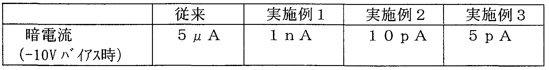
素子の大きさは 5mm X 5 mmとした。 従来構造はサファイア基板上に作製し た。 この時の転位密度は 1 09 c m— 2と推定される。 The size of the element was 5 mm × 5 mm. The conventional structure was fabricated on a sapphire substrate. The dislocation density at this time is estimated to 1 0 9 cm- 2.
[実施例 5 ] 実施例 4と同様に、 実施例 1〜実施例 3の方法で作製した G a N基材の上に、 発光デバイス構造を順次成長して、 発光波長 375 nmの紫外線 LEDを作製し た。 発光デバイス部は、 3種とも全く同じ構造の S QW構造とした。 [Example 5] As in Example 4, a light emitting device structure was sequentially grown on the GaN substrate produced by the method of Examples 1 to 3, and an ultraviolet LED having an emission wavelength of 375 nm was produced. The light-emitting device section has an SQW structure with exactly the same structure for all three types.
これら発光素子に対し、 2 OmAを通電し、 この時の発光出力を比較した。 そ の結果を表 2に示す。 A current of 2 OmA was applied to these light-emitting elements, and the light-emission outputs at this time were compared. The results are shown in Table 2.
表 2

産業上の利用可能性 Industrial applicability
以上説明した通りの本発明の成長方法によれば、 マスク材料を用いること無し に転位密度の低減させることができる。 これにより高品質な G a N系化合物半導 体結晶の作製が可能となる。 この上に L E Dや L Dなどの半導体発光素子ゃ受 光素子、 電子デバイスを作製すれば、 その特性は飛躍的に向上することが期待さ れる。 According to the growth method of the present invention as described above, the dislocation density can be reduced without using a mask material. This makes it possible to produce high-quality GaN-based compound semiconductor crystals. If semiconductor light-emitting devices such as LEDs and LDs, light-receiving devices, and electronic devices are fabricated on top of them, their characteristics are expected to be dramatically improved.
またアンチサ一ファクタント材料を作用させることで、 パターニング等を施さ ずとも実質的に選択成長と同等の効果が得られるため、 アンチサ一ファクタント 処理から半導体層の成長まで成長装置内で連続して行えるので、 製造工程が簡略 ィ匕される。 In addition, by applying an anti-surfactant material, an effect substantially equivalent to selective growth can be obtained without patterning or the like, so that the process from the anti-surfactant treatment to the growth of the semiconductor layer can be continuously performed in the growth apparatus. Thus, the manufacturing process is simplified.
本出願は日本で出願された平成 1 1年特許願第 0 77239号および特願 20 00-03757 7を基礎としており、 それらの内容は本明細書に全て包含され る。 This application is based on a patent application No. 0 77239/1999 filed in Japan and Japanese Patent Application No. 2000-037577, the contents of which are incorporated in full herein.
Claims
Priority Applications (3)
| Application Number | Priority Date | Filing Date | Title |
|---|---|---|---|
| EP00909774A EP1178523B1 (en) | 1999-03-23 | 2000-03-21 | METHOD FOR GROWING GaN COMPOUND SEMICONDUCTOR CRYSTAL AND SEMICONDUCTOR SUBSTRATE |
| US09/937,337 US6700179B1 (en) | 1999-03-23 | 2000-03-21 | Method for growing GaN compound semiconductor crystal and semiconductor substrate |
| DE60033800T DE60033800T2 (en) | 1999-03-23 | 2000-03-21 | GAN SEMICONDUCTOR COMPOSITE CRYSTAL WAXING METHOD AND SEMICONDUCTOR SUBSTRATE |
Applications Claiming Priority (4)
| Application Number | Priority Date | Filing Date | Title |
|---|---|---|---|
| JP7723999 | 1999-03-23 | ||
| JP11/077239 | 1999-03-23 | ||
| JP2000/037577 | 2000-02-16 | ||
| JP2000037577A JP3550070B2 (en) | 1999-03-23 | 2000-02-16 | GaN-based compound semiconductor crystal, growth method thereof and semiconductor substrate |
Related Child Applications (2)
| Application Number | Title | Priority Date | Filing Date |
|---|---|---|---|
| US09/937,337 A-371-Of-International US6700179B1 (en) | 1999-03-23 | 2000-03-21 | Method for growing GaN compound semiconductor crystal and semiconductor substrate |
| US10/703,330 Division US6794210B2 (en) | 1999-03-23 | 2003-11-07 | Method for growing GaN compound semiconductor crystal and semiconductor substrate |
Publications (1)
| Publication Number | Publication Date |
|---|---|
| WO2000057460A1 true WO2000057460A1 (en) | 2000-09-28 |
Family
ID=26418343
Family Applications (1)
| Application Number | Title | Priority Date | Filing Date |
|---|---|---|---|
| PCT/JP2000/001718 Ceased WO2000057460A1 (en) | 1999-03-23 | 2000-03-21 | METHOD FOR GROWING GaN COMPOUND SEMICONDUCTOR CRYSTAL AND SEMICONDUCTOR SUBSTRATE |
Country Status (6)
| Country | Link |
|---|---|
| US (2) | US6700179B1 (en) |
| EP (1) | EP1178523B1 (en) |
| JP (1) | JP3550070B2 (en) |
| KR (1) | KR100635313B1 (en) |
| DE (1) | DE60033800T2 (en) |
| WO (1) | WO2000057460A1 (en) |
Cited By (3)
| Publication number | Priority date | Publication date | Assignee | Title |
|---|---|---|---|---|
| WO2002058120A1 (en) * | 2001-01-18 | 2002-07-25 | Sony Corporation | Crystal film, crystal substrate, and semiconductor device |
| EP1456872A1 (en) * | 2001-12-21 | 2004-09-15 | Aixtron AG | Method for depositing iii-v semiconductor layers on a non iii-v substrate |
| EP1291904A3 (en) * | 2001-09-10 | 2009-10-07 | FUJIFILM Corporation | GaN substrate formed over GaN layer having discretely formed minute holes produced by selective growth |
Families Citing this family (27)
| Publication number | Priority date | Publication date | Assignee | Title |
|---|---|---|---|---|
| JP3112163B2 (en) * | 1999-03-19 | 2000-11-27 | 日本電気株式会社 | Crystal growth method and crystal body thereof |
| JP3274674B2 (en) | 2000-05-16 | 2002-04-15 | 士郎 酒井 | Method for manufacturing gallium nitride-based compound semiconductor |
| JP3274676B2 (en) | 1999-12-20 | 2002-04-15 | 士郎 酒井 | Method for manufacturing gallium nitride-based compound semiconductor |
| JP3809464B2 (en) | 1999-12-14 | 2006-08-16 | 独立行政法人理化学研究所 | Method for forming semiconductor layer |
| JP3476754B2 (en) | 2000-07-28 | 2003-12-10 | 士郎 酒井 | Method for manufacturing gallium nitride-based compound semiconductor |
| US7102158B2 (en) * | 2000-10-23 | 2006-09-05 | General Electric Company | Light-based system for detecting analytes |
| US7615780B2 (en) * | 2000-10-23 | 2009-11-10 | General Electric Company | DNA biosensor and methods for making and using the same |
| JP4644942B2 (en) * | 2001-01-18 | 2011-03-09 | ソニー株式会社 | Crystal film, crystal substrate, and method of manufacturing semiconductor device |
| JP4631214B2 (en) * | 2001-06-05 | 2011-02-16 | ソニー株式会社 | Manufacturing method of nitride semiconductor film |
| JP3544958B2 (en) * | 2001-06-27 | 2004-07-21 | 士郎 酒井 | Method of manufacturing gallium nitride based compound semiconductor |
| JP2003068655A (en) * | 2001-08-27 | 2003-03-07 | Hoya Corp | Production method for compound single crystal |
| JP2004311986A (en) * | 2003-03-25 | 2004-11-04 | Matsushita Electric Ind Co Ltd | Semiconductor device and manufacturing method thereof |
| JP2004363500A (en) * | 2003-06-06 | 2004-12-24 | Satoru Tanaka | Method for producing nitride-based compound semiconductor and nitride-based compound semiconductor |
| JP4581478B2 (en) * | 2004-05-12 | 2010-11-17 | 日亜化学工業株式会社 | Manufacturing method of nitride semiconductor |
| CN100338790C (en) * | 2005-09-30 | 2007-09-19 | 晶能光电(江西)有限公司 | Method for preparing InGaAlN thin film on silicon bulk |
| US20070086916A1 (en) * | 2005-10-14 | 2007-04-19 | General Electric Company | Faceted structure, article, sensor device, and method |
| US8425858B2 (en) * | 2005-10-14 | 2013-04-23 | Morpho Detection, Inc. | Detection apparatus and associated method |
| TWI519686B (en) * | 2005-12-15 | 2016-02-01 | 聖戈班晶體探測器公司 | Low-difference-density gallium nitride (GaN) growth method |
| US9406505B2 (en) * | 2006-02-23 | 2016-08-02 | Allos Semiconductors Gmbh | Nitride semiconductor component and process for its production |
| US7560364B2 (en) * | 2006-05-05 | 2009-07-14 | Applied Materials, Inc. | Dislocation-specific lateral epitaxial overgrowth to reduce dislocation density of nitride films |
| KR101374090B1 (en) * | 2007-07-26 | 2014-03-17 | 아리조나 보드 오브 리젠츠 퍼 앤 온 비하프 오브 아리조나 스테이트 유니버시티 | Epitaxial methods and templates grown by the methods |
| TWI415295B (en) * | 2008-06-24 | 2013-11-11 | 榮創能源科技股份有限公司 | Semiconductor component manufacturing method and structure thereof |
| KR101023173B1 (en) * | 2009-01-22 | 2011-03-18 | 한양대학교 산학협력단 | Epitaxial growth method |
| KR101021775B1 (en) * | 2009-01-29 | 2011-03-15 | 한양대학교 산학협력단 | Epitaxial Growth Method and Epitaxial Layer Lamination Structure Using the Same |
| KR101636032B1 (en) | 2009-08-28 | 2016-07-05 | 서울바이오시스 주식회사 | Light emitting diode having interlayer with high dislocation density and method of fabricating the same |
| JP5591349B2 (en) * | 2010-11-19 | 2014-09-17 | 京セラ株式会社 | Manufacturing method of semiconductor substrate |
| US8728938B2 (en) | 2012-06-13 | 2014-05-20 | Ostendo Technologies, Inc. | Method for substrate pretreatment to achieve high-quality III-nitride epitaxy |
Citations (2)
| Publication number | Priority date | Publication date | Assignee | Title |
|---|---|---|---|---|
| JP2000077336A (en) * | 1998-08-28 | 2000-03-14 | Sony Corp | Semiconductor growth substrate, method of manufacturing the same, and semiconductor device |
| JP2000150388A (en) * | 1998-11-05 | 2000-05-30 | Fuji Electric Co Ltd | Group III nitride semiconductor thin film and method of manufacturing the same |
Family Cites Families (7)
| Publication number | Priority date | Publication date | Assignee | Title |
|---|---|---|---|---|
| US6153010A (en) * | 1997-04-11 | 2000-11-28 | Nichia Chemical Industries Ltd. | Method of growing nitride semiconductors, nitride semiconductor substrate and nitride semiconductor device |
| US5650198A (en) * | 1995-08-18 | 1997-07-22 | The Regents Of The University Of California | Defect reduction in the growth of group III nitrides |
| JP3987898B2 (en) * | 1996-09-03 | 2007-10-10 | 独立行政法人理化学研究所 | Quantum dot forming method and quantum dot structure |
| JP3721674B2 (en) * | 1996-12-05 | 2005-11-30 | ソニー株式会社 | Method for producing nitride III-V compound semiconductor substrate |
| US6348096B1 (en) * | 1997-03-13 | 2002-02-19 | Nec Corporation | Method for manufacturing group III-V compound semiconductors |
| EP0874405A3 (en) * | 1997-03-25 | 2004-09-15 | Mitsubishi Cable Industries, Ltd. | GaN group crystal base member having low dislocation density, use thereof and manufacturing methods thereof |
| US6534332B2 (en) * | 2000-04-21 | 2003-03-18 | The Regents Of The University Of California | Method of growing GaN films with a low density of structural defects using an interlayer |
-
2000
- 2000-02-16 JP JP2000037577A patent/JP3550070B2/en not_active Expired - Fee Related
- 2000-03-21 WO PCT/JP2000/001718 patent/WO2000057460A1/en not_active Ceased
- 2000-03-21 EP EP00909774A patent/EP1178523B1/en not_active Expired - Lifetime
- 2000-03-21 DE DE60033800T patent/DE60033800T2/en not_active Expired - Lifetime
- 2000-03-21 KR KR1020017012094A patent/KR100635313B1/en not_active Expired - Fee Related
- 2000-03-21 US US09/937,337 patent/US6700179B1/en not_active Expired - Fee Related
-
2003
- 2003-11-07 US US10/703,330 patent/US6794210B2/en not_active Expired - Fee Related
Patent Citations (2)
| Publication number | Priority date | Publication date | Assignee | Title |
|---|---|---|---|---|
| JP2000077336A (en) * | 1998-08-28 | 2000-03-14 | Sony Corp | Semiconductor growth substrate, method of manufacturing the same, and semiconductor device |
| JP2000150388A (en) * | 1998-11-05 | 2000-05-30 | Fuji Electric Co Ltd | Group III nitride semiconductor thin film and method of manufacturing the same |
Cited By (3)
| Publication number | Priority date | Publication date | Assignee | Title |
|---|---|---|---|---|
| WO2002058120A1 (en) * | 2001-01-18 | 2002-07-25 | Sony Corporation | Crystal film, crystal substrate, and semiconductor device |
| EP1291904A3 (en) * | 2001-09-10 | 2009-10-07 | FUJIFILM Corporation | GaN substrate formed over GaN layer having discretely formed minute holes produced by selective growth |
| EP1456872A1 (en) * | 2001-12-21 | 2004-09-15 | Aixtron AG | Method for depositing iii-v semiconductor layers on a non iii-v substrate |
Also Published As
| Publication number | Publication date |
|---|---|
| JP2000340511A (en) | 2000-12-08 |
| KR20010108374A (en) | 2001-12-07 |
| EP1178523A4 (en) | 2004-09-29 |
| DE60033800T2 (en) | 2007-11-15 |
| JP3550070B2 (en) | 2004-08-04 |
| KR100635313B1 (en) | 2006-10-18 |
| US6794210B2 (en) | 2004-09-21 |
| EP1178523A1 (en) | 2002-02-06 |
| US20040094084A1 (en) | 2004-05-20 |
| US6700179B1 (en) | 2004-03-02 |
| DE60033800D1 (en) | 2007-04-19 |
| EP1178523B1 (en) | 2007-03-07 |
Similar Documents
| Publication | Publication Date | Title |
|---|---|---|
| JP3550070B2 (en) | GaN-based compound semiconductor crystal, growth method thereof and semiconductor substrate | |
| US6462357B1 (en) | Epitaxial growth of nitride compound semiconductor | |
| JP5244487B2 (en) | Gallium nitride growth substrate and method for manufacturing gallium nitride substrate | |
| WO2009002277A1 (en) | Growth of indium gallium nitride (ingan) on porous gallium nitride (gan) template by metal-organic chemical vapor deposition (mocvd) | |
| JP4529846B2 (en) | III-V nitride semiconductor substrate and method for manufacturing the same | |
| JPH10312971A (en) | III-V compound semiconductor film and its growth method, GaN-based semiconductor film and its formation method, GaN-based semiconductor laminated structure and its formation method, GaN-based semiconductor element and its production method | |
| JP5371430B2 (en) | Semiconductor substrate, method for manufacturing a self-supporting semiconductor substrate by hydride vapor phase epitaxy, and mask layer used therefor | |
| CN1965112B (en) | III group nitride crystal and method for preparation thereof, and III group nitride crystal substrate and semiconductor device | |
| KR20140106590A (en) | Semiconductor substrate and method of forming | |
| WO2004017432A1 (en) | Nitride semiconductor and fabrication method thereof | |
| JP2000277435A (en) | Growth method for garium nitride group compound semiconductor crystal and semiconductor crystal base material | |
| KR100571225B1 (en) | Growth method of nitride compound semiconductor | |
| US20140151714A1 (en) | Gallium nitride substrate and method for fabricating the same | |
| JP3934320B2 (en) | GaN-based semiconductor device and manufacturing method thereof | |
| JP4665286B2 (en) | Semiconductor substrate and manufacturing method thereof | |
| US7361522B2 (en) | Growing lower defect semiconductor crystals on highly lattice-mismatched substrates | |
| JP2011216549A (en) | METHOD OF MANUFACTURING GaN-BASED SEMICONDUCTOR EPITAXIAL SUBSTRATE | |
| KR100682272B1 (en) | Nitride based substrate manufacturing method and nitride based substrate | |
| JP3946976B2 (en) | Semiconductor device, epitaxial substrate, semiconductor device manufacturing method, and epitaxial substrate manufacturing method | |
| JP4583523B2 (en) | III-V nitride semiconductor light emitting device and method for manufacturing the same | |
| JP5015480B2 (en) | Manufacturing method of semiconductor single crystal substrate | |
| KR101020498B1 (en) | Epitaxial growth method | |
| JP4158760B2 (en) | GaN-based semiconductor film and method for manufacturing the same | |
| KR101216363B1 (en) | Gallium Nitride Having Many Voids and Method for Manufacturing the Same | |
| CN109378368B (en) | Method for epitaxial growth of GaN substrate on PSS substrate along semi-polar surface |
Legal Events
| Date | Code | Title | Description |
|---|---|---|---|
| AK | Designated states |
Kind code of ref document: A1 Designated state(s): KR US |
|
| AL | Designated countries for regional patents |
Kind code of ref document: A1 Designated state(s): AT BE CH CY DE DK ES FI FR GB GR IE IT LU MC NL PT SE |
|
| 121 | Ep: the epo has been informed by wipo that ep was designated in this application | ||
| DFPE | Request for preliminary examination filed prior to expiration of 19th month from priority date (pct application filed before 20040101) | ||
| WWE | Wipo information: entry into national phase |
Ref document number: 1020017012094 Country of ref document: KR |
|
| WWE | Wipo information: entry into national phase |
Ref document number: 2000909774 Country of ref document: EP |
|
| WWP | Wipo information: published in national office |
Ref document number: 1020017012094 Country of ref document: KR |
|
| WWE | Wipo information: entry into national phase |
Ref document number: 09937337 Country of ref document: US |
|
| WWP | Wipo information: published in national office |
Ref document number: 2000909774 Country of ref document: EP |
|
| WWG | Wipo information: grant in national office |
Ref document number: 1020017012094 Country of ref document: KR |
|
| WWG | Wipo information: grant in national office |
Ref document number: 2000909774 Country of ref document: EP |