US8470038B2 - Adjustable and fixed assembled bone-tendon-bone graft - Google Patents
Adjustable and fixed assembled bone-tendon-bone graft Download PDFInfo
- Publication number
- US8470038B2 US8470038B2 US11/313,280 US31328005A US8470038B2 US 8470038 B2 US8470038 B2 US 8470038B2 US 31328005 A US31328005 A US 31328005A US 8470038 B2 US8470038 B2 US 8470038B2
- Authority
- US
- United States
- Prior art keywords
- bone
- bone block
- soft tissue
- block
- tendon
- Prior art date
- Legal status (The legal status is an assumption and is not a legal conclusion. Google has not performed a legal analysis and makes no representation as to the accuracy of the status listed.)
- Active, expires
Links
- 210000000988 bone and bone Anatomy 0.000 claims abstract description 1496
- 210000004872 soft tissue Anatomy 0.000 claims abstract description 446
- 210000002435 tendon Anatomy 0.000 claims abstract description 386
- 238000002513 implantation Methods 0.000 claims abstract description 16
- 210000001519 tissue Anatomy 0.000 claims description 132
- 239000007943 implant Substances 0.000 claims description 87
- 210000003041 ligament Anatomy 0.000 claims description 75
- 230000001054 cortical effect Effects 0.000 claims description 49
- 230000006835 compression Effects 0.000 claims description 48
- 238000007906 compression Methods 0.000 claims description 48
- 238000003780 insertion Methods 0.000 claims description 7
- 230000037431 insertion Effects 0.000 claims description 7
- 210000004207 dermis Anatomy 0.000 claims description 6
- 210000003195 fascia Anatomy 0.000 claims description 6
- 210000003516 pericardium Anatomy 0.000 claims description 6
- 241001269524 Dura Species 0.000 claims description 4
- 210000000845 cartilage Anatomy 0.000 claims description 4
- 210000003491 skin Anatomy 0.000 claims description 4
- 230000014759 maintenance of location Effects 0.000 claims description 3
- 230000000712 assembly Effects 0.000 description 45
- 238000000429 assembly Methods 0.000 description 45
- 238000013461 design Methods 0.000 description 36
- 238000000034 method Methods 0.000 description 36
- 230000000052 comparative effect Effects 0.000 description 31
- 239000002775 capsule Substances 0.000 description 24
- 239000000463 material Substances 0.000 description 23
- 230000008439 repair process Effects 0.000 description 16
- 230000008901 benefit Effects 0.000 description 11
- 210000005100 blood-tumour barrier Anatomy 0.000 description 11
- 230000006378 damage Effects 0.000 description 11
- 238000012360 testing method Methods 0.000 description 11
- 210000001264 anterior cruciate ligament Anatomy 0.000 description 10
- 230000008569 process Effects 0.000 description 10
- 238000005520 cutting process Methods 0.000 description 8
- 208000014674 injury Diseases 0.000 description 8
- 125000006850 spacer group Chemical group 0.000 description 8
- 238000001356 surgical procedure Methods 0.000 description 8
- 208000027418 Wounds and injury Diseases 0.000 description 7
- 239000000853 adhesive Substances 0.000 description 5
- 230000001070 adhesive effect Effects 0.000 description 5
- 230000007547 defect Effects 0.000 description 5
- 230000035876 healing Effects 0.000 description 5
- 230000001954 sterilising effect Effects 0.000 description 5
- 238000002054 transplantation Methods 0.000 description 5
- MHAJPDPJQMAIIY-UHFFFAOYSA-N Hydrogen peroxide Chemical compound OO MHAJPDPJQMAIIY-UHFFFAOYSA-N 0.000 description 4
- 230000006872 improvement Effects 0.000 description 4
- 210000003127 knee Anatomy 0.000 description 4
- 238000004519 manufacturing process Methods 0.000 description 4
- 230000000399 orthopedic effect Effects 0.000 description 4
- 238000004659 sterilization and disinfection Methods 0.000 description 4
- 230000007704 transition Effects 0.000 description 4
- 241000894006 Bacteria Species 0.000 description 3
- 241000282412 Homo Species 0.000 description 3
- KFZMGEQAYNKOFK-UHFFFAOYSA-N Isopropanol Chemical compound CC(C)O KFZMGEQAYNKOFK-UHFFFAOYSA-N 0.000 description 3
- RTAQQCXQSZGOHL-UHFFFAOYSA-N Titanium Chemical compound [Ti] RTAQQCXQSZGOHL-UHFFFAOYSA-N 0.000 description 3
- 241000700605 Viruses Species 0.000 description 3
- 230000000890 antigenic effect Effects 0.000 description 3
- 238000004140 cleaning Methods 0.000 description 3
- 238000010276 construction Methods 0.000 description 3
- 239000003814 drug Substances 0.000 description 3
- 239000000835 fiber Substances 0.000 description 3
- 238000004108 freeze drying Methods 0.000 description 3
- 230000000968 intestinal effect Effects 0.000 description 3
- 229910052751 metal Inorganic materials 0.000 description 3
- 239000002184 metal Substances 0.000 description 3
- 102000004169 proteins and genes Human genes 0.000 description 3
- 108090000623 proteins and genes Proteins 0.000 description 3
- 238000011084 recovery Methods 0.000 description 3
- 230000004044 response Effects 0.000 description 3
- 229910001220 stainless steel Inorganic materials 0.000 description 3
- 239000010935 stainless steel Substances 0.000 description 3
- 229920002994 synthetic fiber Polymers 0.000 description 3
- 239000010936 titanium Substances 0.000 description 3
- 229910052719 titanium Inorganic materials 0.000 description 3
- 241000283690 Bos taurus Species 0.000 description 2
- 239000004971 Cross linker Substances 0.000 description 2
- 241000124008 Mammalia Species 0.000 description 2
- 238000013459 approach Methods 0.000 description 2
- 230000001174 ascending effect Effects 0.000 description 2
- 239000000560 biocompatible material Substances 0.000 description 2
- 239000012620 biological material Substances 0.000 description 2
- 230000009977 dual effect Effects 0.000 description 2
- 230000000694 effects Effects 0.000 description 2
- 238000003306 harvesting Methods 0.000 description 2
- 239000011159 matrix material Substances 0.000 description 2
- 238000005259 measurement Methods 0.000 description 2
- 239000000203 mixture Substances 0.000 description 2
- 210000003205 muscle Anatomy 0.000 description 2
- 210000004417 patella Anatomy 0.000 description 2
- 229920001432 poly(L-lactide) Polymers 0.000 description 2
- 229920000642 polymer Polymers 0.000 description 2
- 210000002967 posterior cruciate ligament Anatomy 0.000 description 2
- 230000009467 reduction Effects 0.000 description 2
- 230000001105 regulatory effect Effects 0.000 description 2
- 241000894007 species Species 0.000 description 2
- 239000000126 substance Substances 0.000 description 2
- 230000000007 visual effect Effects 0.000 description 2
- OCKGFTQIICXDQW-ZEQRLZLVSA-N 5-[(1r)-1-hydroxy-2-[4-[(2r)-2-hydroxy-2-(4-methyl-1-oxo-3h-2-benzofuran-5-yl)ethyl]piperazin-1-yl]ethyl]-4-methyl-3h-2-benzofuran-1-one Chemical compound C1=C2C(=O)OCC2=C(C)C([C@@H](O)CN2CCN(CC2)C[C@H](O)C2=CC=C3C(=O)OCC3=C2C)=C1 OCKGFTQIICXDQW-ZEQRLZLVSA-N 0.000 description 1
- 235000002198 Annona diversifolia Nutrition 0.000 description 1
- 241000282472 Canis lupus familiaris Species 0.000 description 1
- 241000283707 Capra Species 0.000 description 1
- 102000008186 Collagen Human genes 0.000 description 1
- 108010035532 Collagen Proteins 0.000 description 1
- 241000283086 Equidae Species 0.000 description 1
- LFQSCWFLJHTTHZ-UHFFFAOYSA-N Ethanol Chemical compound CCO LFQSCWFLJHTTHZ-UHFFFAOYSA-N 0.000 description 1
- 241000282326 Felis catus Species 0.000 description 1
- 241001546602 Horismenus Species 0.000 description 1
- 206010021519 Impaired healing Diseases 0.000 description 1
- 206010060820 Joint injury Diseases 0.000 description 1
- JVTAAEKCZFNVCJ-REOHCLBHSA-N L-lactic acid Chemical compound C[C@H](O)C(O)=O JVTAAEKCZFNVCJ-REOHCLBHSA-N 0.000 description 1
- 241000282838 Lama Species 0.000 description 1
- 241001465754 Metazoa Species 0.000 description 1
- 240000005561 Musa balbisiana Species 0.000 description 1
- 235000018290 Musa x paradisiaca Nutrition 0.000 description 1
- 241001494479 Pecora Species 0.000 description 1
- 241000282887 Suidae Species 0.000 description 1
- 210000001361 achilles tendon Anatomy 0.000 description 1
- 210000003484 anatomy Anatomy 0.000 description 1
- 238000004873 anchoring Methods 0.000 description 1
- 229960000074 biopharmaceutical Drugs 0.000 description 1
- 239000008280 blood Substances 0.000 description 1
- 210000004369 blood Anatomy 0.000 description 1
- 239000001506 calcium phosphate Substances 0.000 description 1
- 229910000389 calcium phosphate Inorganic materials 0.000 description 1
- 235000011010 calcium phosphates Nutrition 0.000 description 1
- 230000001413 cellular effect Effects 0.000 description 1
- 239000000919 ceramic Substances 0.000 description 1
- 230000008859 change Effects 0.000 description 1
- 229920001436 collagen Polymers 0.000 description 1
- 239000002131 composite material Substances 0.000 description 1
- 230000001010 compromised effect Effects 0.000 description 1
- 239000012141 concentrate Substances 0.000 description 1
- 210000002808 connective tissue Anatomy 0.000 description 1
- 238000007796 conventional method Methods 0.000 description 1
- 238000012937 correction Methods 0.000 description 1
- 239000003431 cross linking reagent Substances 0.000 description 1
- 125000004122 cyclic group Chemical group 0.000 description 1
- 230000003247 decreasing effect Effects 0.000 description 1
- 239000003599 detergent Substances 0.000 description 1
- 238000006073 displacement reaction Methods 0.000 description 1
- 238000009826 distribution Methods 0.000 description 1
- 238000005553 drilling Methods 0.000 description 1
- 238000001035 drying Methods 0.000 description 1
- 238000005516 engineering process Methods 0.000 description 1
- 239000012530 fluid Substances 0.000 description 1
- 238000007710 freezing Methods 0.000 description 1
- 230000008014 freezing Effects 0.000 description 1
- 238000000227 grinding Methods 0.000 description 1
- 230000036541 health Effects 0.000 description 1
- 229910052588 hydroxylapatite Inorganic materials 0.000 description 1
- 230000001900 immune effect Effects 0.000 description 1
- 230000028993 immune response Effects 0.000 description 1
- 210000000629 knee joint Anatomy 0.000 description 1
- 238000011068 loading method Methods 0.000 description 1
- 239000003550 marker Substances 0.000 description 1
- 230000005541 medical transmission Effects 0.000 description 1
- 150000002739 metals Chemical class 0.000 description 1
- 238000003801 milling Methods 0.000 description 1
- 238000012986 modification Methods 0.000 description 1
- 230000004048 modification Effects 0.000 description 1
- 239000005445 natural material Substances 0.000 description 1
- 238000004806 packaging method and process Methods 0.000 description 1
- 238000002161 passivation Methods 0.000 description 1
- 210000000426 patellar ligament Anatomy 0.000 description 1
- 244000052769 pathogen Species 0.000 description 1
- 230000001717 pathogenic effect Effects 0.000 description 1
- XYJRXVWERLGGKC-UHFFFAOYSA-D pentacalcium;hydroxide;triphosphate Chemical compound [OH-].[Ca+2].[Ca+2].[Ca+2].[Ca+2].[Ca+2].[O-]P([O-])([O-])=O.[O-]P([O-])([O-])=O.[O-]P([O-])([O-])=O XYJRXVWERLGGKC-UHFFFAOYSA-D 0.000 description 1
- 230000010412 perfusion Effects 0.000 description 1
- 238000011176 pooling Methods 0.000 description 1
- 238000002360 preparation method Methods 0.000 description 1
- 238000002203 pretreatment Methods 0.000 description 1
- 238000012545 processing Methods 0.000 description 1
- 229920006395 saturated elastomer Polymers 0.000 description 1
- 239000007779 soft material Substances 0.000 description 1
- 239000002904 solvent Substances 0.000 description 1
- 239000004575 stone Substances 0.000 description 1
- 238000010998 test method Methods 0.000 description 1
- 210000002303 tibia Anatomy 0.000 description 1
- 230000009466 transformation Effects 0.000 description 1
- 230000008733 trauma Effects 0.000 description 1
- 238000011282 treatment Methods 0.000 description 1
- QORWJWZARLRLPR-UHFFFAOYSA-H tricalcium bis(phosphate) Chemical compound [Ca+2].[Ca+2].[Ca+2].[O-]P([O-])([O-])=O.[O-]P([O-])([O-])=O QORWJWZARLRLPR-UHFFFAOYSA-H 0.000 description 1
- 238000009281 ultraviolet germicidal irradiation Methods 0.000 description 1
- 238000001291 vacuum drying Methods 0.000 description 1
- 239000012808 vapor phase Substances 0.000 description 1
- 210000001835 viscera Anatomy 0.000 description 1
- 235000012773 waffles Nutrition 0.000 description 1
Images


Classifications
-
- A—HUMAN NECESSITIES
- A61—MEDICAL OR VETERINARY SCIENCE; HYGIENE
- A61F—FILTERS IMPLANTABLE INTO BLOOD VESSELS; PROSTHESES; DEVICES PROVIDING PATENCY TO, OR PREVENTING COLLAPSING OF, TUBULAR STRUCTURES OF THE BODY, e.g. STENTS; ORTHOPAEDIC, NURSING OR CONTRACEPTIVE DEVICES; FOMENTATION; TREATMENT OR PROTECTION OF EYES OR EARS; BANDAGES, DRESSINGS OR ABSORBENT PADS; FIRST-AID KITS
- A61F2/00—Filters implantable into blood vessels; Prostheses, i.e. artificial substitutes or replacements for parts of the body; Appliances for connecting them with the body; Devices providing patency to, or preventing collapsing of, tubular structures of the body, e.g. stents
- A61F2/02—Prostheses implantable into the body
- A61F2/08—Muscles; Tendons; Ligaments
- A61F2/0811—Fixation devices for tendons or ligaments
-
- A—HUMAN NECESSITIES
- A61—MEDICAL OR VETERINARY SCIENCE; HYGIENE
- A61F—FILTERS IMPLANTABLE INTO BLOOD VESSELS; PROSTHESES; DEVICES PROVIDING PATENCY TO, OR PREVENTING COLLAPSING OF, TUBULAR STRUCTURES OF THE BODY, e.g. STENTS; ORTHOPAEDIC, NURSING OR CONTRACEPTIVE DEVICES; FOMENTATION; TREATMENT OR PROTECTION OF EYES OR EARS; BANDAGES, DRESSINGS OR ABSORBENT PADS; FIRST-AID KITS
- A61F2/00—Filters implantable into blood vessels; Prostheses, i.e. artificial substitutes or replacements for parts of the body; Appliances for connecting them with the body; Devices providing patency to, or preventing collapsing of, tubular structures of the body, e.g. stents
- A61F2/02—Prostheses implantable into the body
- A61F2/08—Muscles; Tendons; Ligaments
- A61F2/0811—Fixation devices for tendons or ligaments
- A61F2002/0817—Structure of the anchor
- A61F2002/0823—Modular anchors comprising a plurality of separate parts
- A61F2002/0829—Modular anchors comprising a plurality of separate parts without deformation of anchor parts, e.g. fixation screws on bone surface, extending barbs, cams, butterflies, spring-loaded pins
-
- A—HUMAN NECESSITIES
- A61—MEDICAL OR VETERINARY SCIENCE; HYGIENE
- A61F—FILTERS IMPLANTABLE INTO BLOOD VESSELS; PROSTHESES; DEVICES PROVIDING PATENCY TO, OR PREVENTING COLLAPSING OF, TUBULAR STRUCTURES OF THE BODY, e.g. STENTS; ORTHOPAEDIC, NURSING OR CONTRACEPTIVE DEVICES; FOMENTATION; TREATMENT OR PROTECTION OF EYES OR EARS; BANDAGES, DRESSINGS OR ABSORBENT PADS; FIRST-AID KITS
- A61F2/00—Filters implantable into blood vessels; Prostheses, i.e. artificial substitutes or replacements for parts of the body; Appliances for connecting them with the body; Devices providing patency to, or preventing collapsing of, tubular structures of the body, e.g. stents
- A61F2/02—Prostheses implantable into the body
- A61F2/08—Muscles; Tendons; Ligaments
- A61F2/0811—Fixation devices for tendons or ligaments
- A61F2002/0847—Mode of fixation of anchor to tendon or ligament
- A61F2002/0852—Fixation of a loop or U-turn, e.g. eyelets, anchor having multiple holes
-
- A—HUMAN NECESSITIES
- A61—MEDICAL OR VETERINARY SCIENCE; HYGIENE
- A61F—FILTERS IMPLANTABLE INTO BLOOD VESSELS; PROSTHESES; DEVICES PROVIDING PATENCY TO, OR PREVENTING COLLAPSING OF, TUBULAR STRUCTURES OF THE BODY, e.g. STENTS; ORTHOPAEDIC, NURSING OR CONTRACEPTIVE DEVICES; FOMENTATION; TREATMENT OR PROTECTION OF EYES OR EARS; BANDAGES, DRESSINGS OR ABSORBENT PADS; FIRST-AID KITS
- A61F2/00—Filters implantable into blood vessels; Prostheses, i.e. artificial substitutes or replacements for parts of the body; Appliances for connecting them with the body; Devices providing patency to, or preventing collapsing of, tubular structures of the body, e.g. stents
- A61F2/02—Prostheses implantable into the body
- A61F2/08—Muscles; Tendons; Ligaments
- A61F2/0811—Fixation devices for tendons or ligaments
- A61F2002/0847—Mode of fixation of anchor to tendon or ligament
- A61F2002/0858—Fixation of tendon or ligament between anchor and bone, e.g. interference screws, wedges
-
- A—HUMAN NECESSITIES
- A61—MEDICAL OR VETERINARY SCIENCE; HYGIENE
- A61F—FILTERS IMPLANTABLE INTO BLOOD VESSELS; PROSTHESES; DEVICES PROVIDING PATENCY TO, OR PREVENTING COLLAPSING OF, TUBULAR STRUCTURES OF THE BODY, e.g. STENTS; ORTHOPAEDIC, NURSING OR CONTRACEPTIVE DEVICES; FOMENTATION; TREATMENT OR PROTECTION OF EYES OR EARS; BANDAGES, DRESSINGS OR ABSORBENT PADS; FIRST-AID KITS
- A61F2/00—Filters implantable into blood vessels; Prostheses, i.e. artificial substitutes or replacements for parts of the body; Appliances for connecting them with the body; Devices providing patency to, or preventing collapsing of, tubular structures of the body, e.g. stents
- A61F2/02—Prostheses implantable into the body
- A61F2/08—Muscles; Tendons; Ligaments
- A61F2/0811—Fixation devices for tendons or ligaments
- A61F2002/0847—Mode of fixation of anchor to tendon or ligament
- A61F2002/0864—Fixation of tendon or ligament between anchor elements, e.g. by additional screws in the anchor, anchor crimped around tendon
-
- A—HUMAN NECESSITIES
- A61—MEDICAL OR VETERINARY SCIENCE; HYGIENE
- A61F—FILTERS IMPLANTABLE INTO BLOOD VESSELS; PROSTHESES; DEVICES PROVIDING PATENCY TO, OR PREVENTING COLLAPSING OF, TUBULAR STRUCTURES OF THE BODY, e.g. STENTS; ORTHOPAEDIC, NURSING OR CONTRACEPTIVE DEVICES; FOMENTATION; TREATMENT OR PROTECTION OF EYES OR EARS; BANDAGES, DRESSINGS OR ABSORBENT PADS; FIRST-AID KITS
- A61F2/00—Filters implantable into blood vessels; Prostheses, i.e. artificial substitutes or replacements for parts of the body; Appliances for connecting them with the body; Devices providing patency to, or preventing collapsing of, tubular structures of the body, e.g. stents
- A61F2/02—Prostheses implantable into the body
- A61F2/08—Muscles; Tendons; Ligaments
- A61F2/0811—Fixation devices for tendons or ligaments
- A61F2002/0876—Position of anchor in respect to the bone
- A61F2002/0882—Anchor in or on top of a bone tunnel, i.e. a hole running through the entire bone
-
- A—HUMAN NECESSITIES
- A61—MEDICAL OR VETERINARY SCIENCE; HYGIENE
- A61F—FILTERS IMPLANTABLE INTO BLOOD VESSELS; PROSTHESES; DEVICES PROVIDING PATENCY TO, OR PREVENTING COLLAPSING OF, TUBULAR STRUCTURES OF THE BODY, e.g. STENTS; ORTHOPAEDIC, NURSING OR CONTRACEPTIVE DEVICES; FOMENTATION; TREATMENT OR PROTECTION OF EYES OR EARS; BANDAGES, DRESSINGS OR ABSORBENT PADS; FIRST-AID KITS
- A61F2/00—Filters implantable into blood vessels; Prostheses, i.e. artificial substitutes or replacements for parts of the body; Appliances for connecting them with the body; Devices providing patency to, or preventing collapsing of, tubular structures of the body, e.g. stents
- A61F2/02—Prostheses implantable into the body
- A61F2/28—Bones
- A61F2002/2835—Bone graft implants for filling a bony defect or an endoprosthesis cavity, e.g. by synthetic material or biological material
- A61F2002/2839—Bone plugs or bone graft dowels
-
- A—HUMAN NECESSITIES
- A61—MEDICAL OR VETERINARY SCIENCE; HYGIENE
- A61F—FILTERS IMPLANTABLE INTO BLOOD VESSELS; PROSTHESES; DEVICES PROVIDING PATENCY TO, OR PREVENTING COLLAPSING OF, TUBULAR STRUCTURES OF THE BODY, e.g. STENTS; ORTHOPAEDIC, NURSING OR CONTRACEPTIVE DEVICES; FOMENTATION; TREATMENT OR PROTECTION OF EYES OR EARS; BANDAGES, DRESSINGS OR ABSORBENT PADS; FIRST-AID KITS
- A61F2/00—Filters implantable into blood vessels; Prostheses, i.e. artificial substitutes or replacements for parts of the body; Appliances for connecting them with the body; Devices providing patency to, or preventing collapsing of, tubular structures of the body, e.g. stents
- A61F2/02—Prostheses implantable into the body
- A61F2/30—Joints
- A61F2002/30001—Additional features of subject-matter classified in A61F2/28, A61F2/30 and subgroups thereof
- A61F2002/30003—Material related properties of the prosthesis or of a coating on the prosthesis
- A61F2002/30004—Material related properties of the prosthesis or of a coating on the prosthesis the prosthesis being made from materials having different values of a given property at different locations within the same prosthesis
- A61F2002/30057—Material related properties of the prosthesis or of a coating on the prosthesis the prosthesis being made from materials having different values of a given property at different locations within the same prosthesis made from both cortical and cancellous adjacent parts
-
- A—HUMAN NECESSITIES
- A61—MEDICAL OR VETERINARY SCIENCE; HYGIENE
- A61F—FILTERS IMPLANTABLE INTO BLOOD VESSELS; PROSTHESES; DEVICES PROVIDING PATENCY TO, OR PREVENTING COLLAPSING OF, TUBULAR STRUCTURES OF THE BODY, e.g. STENTS; ORTHOPAEDIC, NURSING OR CONTRACEPTIVE DEVICES; FOMENTATION; TREATMENT OR PROTECTION OF EYES OR EARS; BANDAGES, DRESSINGS OR ABSORBENT PADS; FIRST-AID KITS
- A61F2220/00—Fixations or connections for prostheses classified in groups A61F2/00 - A61F2/26 or A61F2/82 or A61F9/00 or A61F11/00 or subgroups thereof
- A61F2220/0008—Fixation appliances for connecting prostheses to the body
- A61F2220/0016—Fixation appliances for connecting prostheses to the body with sharp anchoring protrusions, e.g. barbs, pins, spikes
-
- A—HUMAN NECESSITIES
- A61—MEDICAL OR VETERINARY SCIENCE; HYGIENE
- A61F—FILTERS IMPLANTABLE INTO BLOOD VESSELS; PROSTHESES; DEVICES PROVIDING PATENCY TO, OR PREVENTING COLLAPSING OF, TUBULAR STRUCTURES OF THE BODY, e.g. STENTS; ORTHOPAEDIC, NURSING OR CONTRACEPTIVE DEVICES; FOMENTATION; TREATMENT OR PROTECTION OF EYES OR EARS; BANDAGES, DRESSINGS OR ABSORBENT PADS; FIRST-AID KITS
- A61F2220/00—Fixations or connections for prostheses classified in groups A61F2/00 - A61F2/26 or A61F2/82 or A61F9/00 or A61F11/00 or subgroups thereof
- A61F2220/0025—Connections or couplings between prosthetic parts, e.g. between modular parts; Connecting elements
- A61F2220/0033—Connections or couplings between prosthetic parts, e.g. between modular parts; Connecting elements made by longitudinally pushing a protrusion into a complementary-shaped recess, e.g. held by friction fit
-
- A—HUMAN NECESSITIES
- A61—MEDICAL OR VETERINARY SCIENCE; HYGIENE
- A61F—FILTERS IMPLANTABLE INTO BLOOD VESSELS; PROSTHESES; DEVICES PROVIDING PATENCY TO, OR PREVENTING COLLAPSING OF, TUBULAR STRUCTURES OF THE BODY, e.g. STENTS; ORTHOPAEDIC, NURSING OR CONTRACEPTIVE DEVICES; FOMENTATION; TREATMENT OR PROTECTION OF EYES OR EARS; BANDAGES, DRESSINGS OR ABSORBENT PADS; FIRST-AID KITS
- A61F2220/00—Fixations or connections for prostheses classified in groups A61F2/00 - A61F2/26 or A61F2/82 or A61F9/00 or A61F11/00 or subgroups thereof
- A61F2220/0025—Connections or couplings between prosthetic parts, e.g. between modular parts; Connecting elements
- A61F2220/0041—Connections or couplings between prosthetic parts, e.g. between modular parts; Connecting elements using additional screws, bolts, dowels or rivets, e.g. connecting screws
-
- A—HUMAN NECESSITIES
- A61—MEDICAL OR VETERINARY SCIENCE; HYGIENE
- A61F—FILTERS IMPLANTABLE INTO BLOOD VESSELS; PROSTHESES; DEVICES PROVIDING PATENCY TO, OR PREVENTING COLLAPSING OF, TUBULAR STRUCTURES OF THE BODY, e.g. STENTS; ORTHOPAEDIC, NURSING OR CONTRACEPTIVE DEVICES; FOMENTATION; TREATMENT OR PROTECTION OF EYES OR EARS; BANDAGES, DRESSINGS OR ABSORBENT PADS; FIRST-AID KITS
- A61F2230/00—Geometry of prostheses classified in groups A61F2/00 - A61F2/26 or A61F2/82 or A61F9/00 or A61F11/00 or subgroups thereof
- A61F2230/0002—Two-dimensional shapes, e.g. cross-sections
- A61F2230/0004—Rounded shapes, e.g. with rounded corners
- A61F2230/0008—Rounded shapes, e.g. with rounded corners elliptical or oval
-
- A—HUMAN NECESSITIES
- A61—MEDICAL OR VETERINARY SCIENCE; HYGIENE
- A61F—FILTERS IMPLANTABLE INTO BLOOD VESSELS; PROSTHESES; DEVICES PROVIDING PATENCY TO, OR PREVENTING COLLAPSING OF, TUBULAR STRUCTURES OF THE BODY, e.g. STENTS; ORTHOPAEDIC, NURSING OR CONTRACEPTIVE DEVICES; FOMENTATION; TREATMENT OR PROTECTION OF EYES OR EARS; BANDAGES, DRESSINGS OR ABSORBENT PADS; FIRST-AID KITS
- A61F2230/00—Geometry of prostheses classified in groups A61F2/00 - A61F2/26 or A61F2/82 or A61F9/00 or A61F11/00 or subgroups thereof
- A61F2230/0002—Two-dimensional shapes, e.g. cross-sections
- A61F2230/0017—Angular shapes
- A61F2230/0019—Angular shapes rectangular
-
- A—HUMAN NECESSITIES
- A61—MEDICAL OR VETERINARY SCIENCE; HYGIENE
- A61F—FILTERS IMPLANTABLE INTO BLOOD VESSELS; PROSTHESES; DEVICES PROVIDING PATENCY TO, OR PREVENTING COLLAPSING OF, TUBULAR STRUCTURES OF THE BODY, e.g. STENTS; ORTHOPAEDIC, NURSING OR CONTRACEPTIVE DEVICES; FOMENTATION; TREATMENT OR PROTECTION OF EYES OR EARS; BANDAGES, DRESSINGS OR ABSORBENT PADS; FIRST-AID KITS
- A61F2230/00—Geometry of prostheses classified in groups A61F2/00 - A61F2/26 or A61F2/82 or A61F9/00 or A61F11/00 or subgroups thereof
- A61F2230/0002—Two-dimensional shapes, e.g. cross-sections
- A61F2230/0017—Angular shapes
- A61F2230/0021—Angular shapes square
-
- A—HUMAN NECESSITIES
- A61—MEDICAL OR VETERINARY SCIENCE; HYGIENE
- A61F—FILTERS IMPLANTABLE INTO BLOOD VESSELS; PROSTHESES; DEVICES PROVIDING PATENCY TO, OR PREVENTING COLLAPSING OF, TUBULAR STRUCTURES OF THE BODY, e.g. STENTS; ORTHOPAEDIC, NURSING OR CONTRACEPTIVE DEVICES; FOMENTATION; TREATMENT OR PROTECTION OF EYES OR EARS; BANDAGES, DRESSINGS OR ABSORBENT PADS; FIRST-AID KITS
- A61F2230/00—Geometry of prostheses classified in groups A61F2/00 - A61F2/26 or A61F2/82 or A61F9/00 or A61F11/00 or subgroups thereof
- A61F2230/0002—Two-dimensional shapes, e.g. cross-sections
- A61F2230/0017—Angular shapes
- A61F2230/0023—Angular shapes triangular
-
- A—HUMAN NECESSITIES
- A61—MEDICAL OR VETERINARY SCIENCE; HYGIENE
- A61F—FILTERS IMPLANTABLE INTO BLOOD VESSELS; PROSTHESES; DEVICES PROVIDING PATENCY TO, OR PREVENTING COLLAPSING OF, TUBULAR STRUCTURES OF THE BODY, e.g. STENTS; ORTHOPAEDIC, NURSING OR CONTRACEPTIVE DEVICES; FOMENTATION; TREATMENT OR PROTECTION OF EYES OR EARS; BANDAGES, DRESSINGS OR ABSORBENT PADS; FIRST-AID KITS
- A61F2230/00—Geometry of prostheses classified in groups A61F2/00 - A61F2/26 or A61F2/82 or A61F9/00 or A61F11/00 or subgroups thereof
- A61F2230/0002—Two-dimensional shapes, e.g. cross-sections
- A61F2230/0017—Angular shapes
- A61F2230/0026—Angular shapes trapezoidal
-
- A—HUMAN NECESSITIES
- A61—MEDICAL OR VETERINARY SCIENCE; HYGIENE
- A61F—FILTERS IMPLANTABLE INTO BLOOD VESSELS; PROSTHESES; DEVICES PROVIDING PATENCY TO, OR PREVENTING COLLAPSING OF, TUBULAR STRUCTURES OF THE BODY, e.g. STENTS; ORTHOPAEDIC, NURSING OR CONTRACEPTIVE DEVICES; FOMENTATION; TREATMENT OR PROTECTION OF EYES OR EARS; BANDAGES, DRESSINGS OR ABSORBENT PADS; FIRST-AID KITS
- A61F2230/00—Geometry of prostheses classified in groups A61F2/00 - A61F2/26 or A61F2/82 or A61F9/00 or A61F11/00 or subgroups thereof
- A61F2230/0002—Two-dimensional shapes, e.g. cross-sections
- A61F2230/0028—Shapes in the form of latin or greek characters
- A61F2230/0045—Omega-shaped
-
- A—HUMAN NECESSITIES
- A61—MEDICAL OR VETERINARY SCIENCE; HYGIENE
- A61F—FILTERS IMPLANTABLE INTO BLOOD VESSELS; PROSTHESES; DEVICES PROVIDING PATENCY TO, OR PREVENTING COLLAPSING OF, TUBULAR STRUCTURES OF THE BODY, e.g. STENTS; ORTHOPAEDIC, NURSING OR CONTRACEPTIVE DEVICES; FOMENTATION; TREATMENT OR PROTECTION OF EYES OR EARS; BANDAGES, DRESSINGS OR ABSORBENT PADS; FIRST-AID KITS
- A61F2230/00—Geometry of prostheses classified in groups A61F2/00 - A61F2/26 or A61F2/82 or A61F9/00 or A61F11/00 or subgroups thereof
- A61F2230/0002—Two-dimensional shapes, e.g. cross-sections
- A61F2230/0028—Shapes in the form of latin or greek characters
- A61F2230/0047—Pi-shaped
-
- A—HUMAN NECESSITIES
- A61—MEDICAL OR VETERINARY SCIENCE; HYGIENE
- A61F—FILTERS IMPLANTABLE INTO BLOOD VESSELS; PROSTHESES; DEVICES PROVIDING PATENCY TO, OR PREVENTING COLLAPSING OF, TUBULAR STRUCTURES OF THE BODY, e.g. STENTS; ORTHOPAEDIC, NURSING OR CONTRACEPTIVE DEVICES; FOMENTATION; TREATMENT OR PROTECTION OF EYES OR EARS; BANDAGES, DRESSINGS OR ABSORBENT PADS; FIRST-AID KITS
- A61F2230/00—Geometry of prostheses classified in groups A61F2/00 - A61F2/26 or A61F2/82 or A61F9/00 or A61F11/00 or subgroups thereof
- A61F2230/0002—Two-dimensional shapes, e.g. cross-sections
- A61F2230/0028—Shapes in the form of latin or greek characters
- A61F2230/0054—V-shaped
-
- A—HUMAN NECESSITIES
- A61—MEDICAL OR VETERINARY SCIENCE; HYGIENE
- A61F—FILTERS IMPLANTABLE INTO BLOOD VESSELS; PROSTHESES; DEVICES PROVIDING PATENCY TO, OR PREVENTING COLLAPSING OF, TUBULAR STRUCTURES OF THE BODY, e.g. STENTS; ORTHOPAEDIC, NURSING OR CONTRACEPTIVE DEVICES; FOMENTATION; TREATMENT OR PROTECTION OF EYES OR EARS; BANDAGES, DRESSINGS OR ABSORBENT PADS; FIRST-AID KITS
- A61F2230/00—Geometry of prostheses classified in groups A61F2/00 - A61F2/26 or A61F2/82 or A61F9/00 or A61F11/00 or subgroups thereof
- A61F2230/0063—Three-dimensional shapes
- A61F2230/0073—Quadric-shaped
- A61F2230/0076—Quadric-shaped ellipsoidal or ovoid
-
- A—HUMAN NECESSITIES
- A61—MEDICAL OR VETERINARY SCIENCE; HYGIENE
- A61F—FILTERS IMPLANTABLE INTO BLOOD VESSELS; PROSTHESES; DEVICES PROVIDING PATENCY TO, OR PREVENTING COLLAPSING OF, TUBULAR STRUCTURES OF THE BODY, e.g. STENTS; ORTHOPAEDIC, NURSING OR CONTRACEPTIVE DEVICES; FOMENTATION; TREATMENT OR PROTECTION OF EYES OR EARS; BANDAGES, DRESSINGS OR ABSORBENT PADS; FIRST-AID KITS
- A61F2250/00—Special features of prostheses classified in groups A61F2/00 - A61F2/26 or A61F2/82 or A61F9/00 or A61F11/00 or subgroups thereof
- A61F2250/0014—Special features of prostheses classified in groups A61F2/00 - A61F2/26 or A61F2/82 or A61F9/00 or A61F11/00 or subgroups thereof having different values of a given property or geometrical feature, e.g. mechanical property or material property, at different locations within the same prosthesis
- A61F2250/0025—Special features of prostheses classified in groups A61F2/00 - A61F2/26 or A61F2/82 or A61F9/00 or A61F11/00 or subgroups thereof having different values of a given property or geometrical feature, e.g. mechanical property or material property, at different locations within the same prosthesis differing in roughness
-
- A—HUMAN NECESSITIES
- A61—MEDICAL OR VETERINARY SCIENCE; HYGIENE
- A61F—FILTERS IMPLANTABLE INTO BLOOD VESSELS; PROSTHESES; DEVICES PROVIDING PATENCY TO, OR PREVENTING COLLAPSING OF, TUBULAR STRUCTURES OF THE BODY, e.g. STENTS; ORTHOPAEDIC, NURSING OR CONTRACEPTIVE DEVICES; FOMENTATION; TREATMENT OR PROTECTION OF EYES OR EARS; BANDAGES, DRESSINGS OR ABSORBENT PADS; FIRST-AID KITS
- A61F2250/00—Special features of prostheses classified in groups A61F2/00 - A61F2/26 or A61F2/82 or A61F9/00 or A61F11/00 or subgroups thereof
- A61F2250/0014—Special features of prostheses classified in groups A61F2/00 - A61F2/26 or A61F2/82 or A61F9/00 or A61F11/00 or subgroups thereof having different values of a given property or geometrical feature, e.g. mechanical property or material property, at different locations within the same prosthesis
- A61F2250/0026—Special features of prostheses classified in groups A61F2/00 - A61F2/26 or A61F2/82 or A61F9/00 or A61F11/00 or subgroups thereof having different values of a given property or geometrical feature, e.g. mechanical property or material property, at different locations within the same prosthesis differing in surface structures
-
- A—HUMAN NECESSITIES
- A61—MEDICAL OR VETERINARY SCIENCE; HYGIENE
- A61F—FILTERS IMPLANTABLE INTO BLOOD VESSELS; PROSTHESES; DEVICES PROVIDING PATENCY TO, OR PREVENTING COLLAPSING OF, TUBULAR STRUCTURES OF THE BODY, e.g. STENTS; ORTHOPAEDIC, NURSING OR CONTRACEPTIVE DEVICES; FOMENTATION; TREATMENT OR PROTECTION OF EYES OR EARS; BANDAGES, DRESSINGS OR ABSORBENT PADS; FIRST-AID KITS
- A61F2250/00—Special features of prostheses classified in groups A61F2/00 - A61F2/26 or A61F2/82 or A61F9/00 or A61F11/00 or subgroups thereof
- A61F2250/0058—Additional features; Implant or prostheses properties not otherwise provided for
- A61F2250/006—Additional features; Implant or prostheses properties not otherwise provided for modular
- A61F2250/0062—Kits of prosthetic parts to be assembled in various combinations for forming different prostheses
-
- A—HUMAN NECESSITIES
- A61—MEDICAL OR VETERINARY SCIENCE; HYGIENE
- A61F—FILTERS IMPLANTABLE INTO BLOOD VESSELS; PROSTHESES; DEVICES PROVIDING PATENCY TO, OR PREVENTING COLLAPSING OF, TUBULAR STRUCTURES OF THE BODY, e.g. STENTS; ORTHOPAEDIC, NURSING OR CONTRACEPTIVE DEVICES; FOMENTATION; TREATMENT OR PROTECTION OF EYES OR EARS; BANDAGES, DRESSINGS OR ABSORBENT PADS; FIRST-AID KITS
- A61F2250/00—Special features of prostheses classified in groups A61F2/00 - A61F2/26 or A61F2/82 or A61F9/00 or A61F11/00 or subgroups thereof
- A61F2250/0058—Additional features; Implant or prostheses properties not otherwise provided for
- A61F2250/0081—Prosthesis for animals
Definitions
- the present invention is related to the field of bone-tendon-bone grafts and components thereof, for implantation in mammals, particularly for implantation in humans. More specifically, the present invention is directed to an intermediate bone block for use in bone-tendon-bone (BTB) grafts wherein the intermediate bone block is capable of being used with the same or a different bone block to form a bone block assembly that has an enhanced gripping feature for gripping soft tissue to form an assembled bone-tendon-bone graft suitable for implantation into a patient.
- BTB bone-tendon-bone
- the bone-tendon-bone grafts of the present invention are useful because they offer surgeons and patients the advantages of full internal tendon capture, bone to bone contact at the healing interface, use of any suitable tendon specimen, construction to a predetermined gage length, and adherence to preferred surgical technique and fixation methods, while maintaining a significantly increased tensile strength over BTB grafts formed by stitching, stapling or compression alone.
- Orthopedic medicine is increasingly becoming aware of the vast potential and advantages of using bone/tendon/bone grafts to repair common joint injuries, such as Anterior Cruciate Ligament (ACL) or Posterior Cruciate Ligament (PCL) tears.
- ACL Anterior Cruciate Ligament
- PCL Posterior Cruciate Ligament
- One technique that is currently used for repairing these types of injuries involves surgically reconnecting the torn portions of a damaged ligament. However, this technique is often not possible, especially when the damage to the ligament is extensive.
- another technique commonly performed involves redirecting tendons to provide increased support to a damaged knee.
- Bone-tendon-bone (BTB) grafts of the prior art are made in one of two ways: (1) by harvesting a naturally occurring tendon/ligament and portions of the bone(s) to which it is attached, thus maintaining the naturally occurring attachment of tendon/ligament and bone; or (2) by attaching the opposing ends of one or more pieces of tendon, ligament or a synthetic material to separate bone blocks.
- BTB is used for historical reasons.
- a “tendon” is a collagenous cord that attaches muscle to its point of origin, typically to bone.
- a “ligament” is a band of collagenous tissue that connects bone or supports viscera.
- BTB would more properly be called a bone-ligament-bone implant.
- BTB became adopted by the art. We have used the term BTB to encompass all of the bone-soft tissue grafts described herein.
- Tendons are fibrous semi-hard materials that are slippery and difficult to grip.
- the tendon has a tendency to squirm and slip when compressed between boney surfaces, much like a banana peel compressed between the floor and one's foot.
- One solution that is commonly used is to bite the tendon with a component that has some sort of teeth or threads, providing improved gripping over a flat surface.
- teeth or threads have a tendency to cut into the tendon fibers when the tendon is pulled at high tensile strength.
- most assembled BTBs provide some sort of trade-off between reducing slipping and squirming by biting which does not allow for achievement of maximum tensile strength.
- U.S. Pat. No. 5,370,662 (“the '662 patent”), which issued to Stone on Dec. 6, 1994 and which is entitled “Suture Anchor Assembly,” discloses the use of a screw made from titanium, stainless steel, or some other durable, non-degradable, biocompatible material having a portal at one end for attaching a suture connected to a soft material, such as a ligament or tendon.
- One problem with such a device is that the screw, although bio-compatible, will never become assimilated into the patient's body.
- a second problem is that the tendon or ligament will never form a natural attachment to the screw.
- the '560 patent discloses a wedge-shaped interference screw made from a biocompatible material for use with a ligament and with two bone blocks for performing anterior cruciate ligament repairs.
- a bio-compatible, wedge-shaped interference screw, a bone block and a ligament are inserted into an osseous tunnel drilled into a bone of a patient in need of a ligament repair.
- the interference screw compresses the flat surface of a bone block against a ligament that is pressed into the wall of the osseous tunnel.
- a second interference screw compresses a second bone block against an opposing end of the ligament in a second osseous tunnel drilled in a second bone in need of ligament repair. It is more difficult to pull a predetermined tension on the tendon because the tendon slips in the bone tunnel and uncontrollably alters the tension when the interference screw is being threaded in the bone tunnel.
- the slippery ligament is also subject to slippage when compressed between the bone block and the tunnel wall. Such slippage results in a loss of tension in the joint. In the case of an anterior cruciate ligament (ACL) repair, this loss of tension causes a wobbly knee. This is undesirable in any human and particularly athletes.
- This “U” shape of the tendon captures the tendon in the first bone tunnel, but leaves two free tendon ends to be secured in the second bone tunnel.
- the bone block which presses the ligament against the walls of the osseous tunnel contains two grooves for “locking” (col. 7, line 2) the ligament in place, and “restricting excessive compression on the ligament” (col. 7, lines 8-9).
- the “locking” of the tendon against the tunnel wall still leaves the tendon free to move against the tunnel wall near the ends of the anchor body. This leads to impaired healing and recovery due to tendon to bone contact within the tunnel and also due to micromotions of the tendon within the tunnel.
- the location of the tendon in the locking grooves is a function of the anchor body design and is not a controlled design parameter. Thus, the tendon placement with respect to either the tunnel wall or the tunnel centerline cannot be matched to particular surgical needs or to surgeon preference.
- a tendon is bound in an internal chamber created in the bone blocks.
- a plurality of cams reverse the direction of the tendon several times and cancellous chips packed in any open space bite into the tendon to keep it from slipping.
- a screw compresses the tendon against the side of an internal chamber.
- one end of a tendon is doubled over and the doubled over end is held in place by a series of grooves and rings. While all of these embodiments are useful, they each are challenging to manufacture and/or assemble due to their inherent complexity and reliance on small or intricate parts. It is an object of the present invention to provide a BTB having a robust design, simple components, ease of manufacturability, and high reliability, all while maintaining an acceptable tensile strength, stiffness, and elongation performance. This is important for all BTB grafts, especially for those implanted in athletes and other individuals where maximum performance is required.
- BTB One isolated and purified BTB that is not hindered by slippage or cut fibers when subjected to high tensile pulling is disclosed in commonly assigned U.S. Pat. No. 6,497,726 (“the '726 patent”) which issued on Dec. 24, 2002 to Carter et al.
- the '726 patent discloses the use of natural BTBs that are cut from allograft or xenograft sources, commonly referred to as “pre-shaped BTBs.”
- pre-shaped BTBs commonly referred to as “pre-shaped BTBs.”
- the BTB is cut as a single piece from a section of the patella (bone), patellar tendon and the tibia (bone) of the donor.
- One problem is that only 2-3 grafts can be obtained per knee of the donor, depending upon the donor's age and health.
- BTB grafts in large quantities. It is also an object of the present invention to make BTB grafts having high tensile strength, suitable for ACL repairs, from tendon and bone components, wherein the BTBs are constructed so as to minimize the art recognized slippage and tearing associated with conventional modes of construction as described above.
- Another problem with pre-shaped (natural) BTBs is that the size of the BTB or the length of the tendon between the two bone pieces cannot be precisely selected.
- the present invention relates to a bone-tendon-bone graft and components thereof.
- Various embodiments relate to bone blocks (alternatively referred to as “intermediate bone blocks”) that can be used to secure soft tissue (e.g., tendon) in a patient.
- Embodiments of intermediate bone blocks of the present invention may be used singly or in combination with other bone blocks to form bone block assemblies for securing soft tissue.
- an implant of the present invention comprises a first bone component at a first end of said implant, a second bone component at a second end of said implant; and a segment of soft tissue having a first end, a midsection and a second end; wherein said first bone component comprises a bone block assembly for securing soft tissue comprising a first intermediate bone block and a second intermediate bone block, said first intermediate bone block and said second intermediate bone block sandwiching said soft tissue therebetween; and wherein the first end and the second end of said soft tissue contact said first bone component, and the midsection of said soft tissue contacts said second bone component.
- a second embodiment of an implant of the present invention comprises a first bone component at a first end of said implant, a second bone component at a second end of said implant; and a segment of soft tissue of sufficient length to extend between said first and second bone components; wherein said first bone component comprises a bone block assembly for securing soft tissue comprising a first intermediate bone block and a second intermediate bone block, said first intermediate bone block and said second intermediate bone block sandwiching said soft tissue therebetween, wherein said second bone component comprises a bone block assembly comprising a first intermediate bone block and a second intermediate bone block, said first intermediate bone block and said second intermediate bone block sandwiching said soft tissue therebetween, and wherein said soft tissue extends from said first bone component to said second bone component, is doubled back through or around said second bone component, and extends back to said first bone component.
- a third embodiment of an implant of the present invention comprises a first bone component at a first end of said implant a second bone component at a second end of said implant; and a segment of soft tissue of sufficient length to extend between said first and second bone components; wherein said first bone component comprises a bone block assembly for securing soft tissue comprising a first intermediate bone block and a second intermediate bone block, said first intermediate bone block and said second intermediate bone block sandwiching said soft tissue therebetween, wherein said second bone component comprises an intermediate bone block comprising a top, a bottom, at least two lateral sides connecting said top and said bottom, and at least one portal through said intermediate bone block from said top side to said bottom side, and wherein said soft tissue contacts the first bone component in at least two places along the length of said soft tissue, and said soft tissue contacts the second bone component in at least one place along the length of said soft tissue.
- the soft tissue extends from the first bone component to the second bone component, is doubled back through said second bone component, and ends underneath said first bone component such that it is compressed into the bone tunnel wall when an interference screw is used to secure the first bone component.
- An implant of the present invention has only one bone component.
- An implant of this type comprises a soft tissue component and a bone component; wherein said bone component comprises a top, a bottom, a leading end, a trailing end, at least two lateral sides connecting said top and said bottom, and at least one portal through said bone implant from said top side to said bottom side sized to accept said soft tissue.
- one of said lateral sides comprises a retention feature for maintaining the implant at the site of implantation, selected from the group consisting of an interference screw groove, angled teeth, symmetrical teeth, and threads. It s also preferred that portal be located at said leading end, said leading end being rounded to aid in insertion of the implant.
- a bone block (hereinafter Applicants' “intermediate bone block”) provides the bone block with an unexpectedly superior grip of a tendon (or other soft tissue), relative to bone blocks with untextured (smooth) or textured tissue engaging surfaces. It is thought that the cavities on the tendon engaging face capture uncompressed tendon (or soft tissue) from above the cavity and the overflow of adjacent compressed tendon (or soft tissue) allowing the compressive surfaces of the Applicants' intermediate bone block to grab and hold the tendon (or soft tissue) without damaging it, rather than float on it.
- a preferred cavity is a channel in the tendon (or soft tissue) engaging face of the bone block.
- cavities have cross-sectional profiles that are rectangular, square, semi-circular, semi-ovular, triangular, trapezoidal, sinusoidal, curvilinear, dovetail, omega or a combination thereof.
- the cavity has an omega (“ ⁇ ”) shaped cross-section, i.e., is an omega shaped cavity.
- omega omega
- the term “omega” shaped cross section is meant that the lateral cross section of the cavity that is cut into the face of the intermediate bone block has the shape of the Greek letter “ ⁇ ”.
- compression surfaces and cavities result in a an intermediate bone block that has the advantages of full internal tendon capture, bone to bone contact at the healing interface, and the use of any suitable soft tissue (e.g., tendon) specimen, and adherence to preferred surgical technique and fixation methods, while maintaining a significantly increased tensile strength over BTBs formed by stitching, stapling or compression alone.
- the cross-sectional shape of the cavity preferably, a channel
- omega shaped “ ⁇ ” an even more enhanced gripping of the soft tissue (e.g., tendon) between the opposing faces of the bone blocks was achieved.
- the undercut shape of the omega cavity or channel (collectively “cavity”) allows it to advantageously capture and hold the uncompressed and overflow soft tissue.
- the omega cavity has a unique shape because it has a narrower mouth than the width of its cross section due to the fact that the face of the bone block is undercut and the undercut is rounded. This feature allows the soft tissue to enter the undercut cavity and expand in a direction perpendicular to the direction of compression immediately above on the tissue engaging surface of the bone block.
- the rounded profile of the undercut cavity also greatly reduces stress concentrations and allows the soft tissue to distribute the compressive load more evenly across the entire cavity.
- the omega “ ⁇ ” cavity gently grips the soft tissue without cutting, and prevents it from slipping, sliding or flowing in the direction it is being pulled or squeezed.
- the edge of the omega cavity unlike the edges of teeth or ridges (see FIGS. 6A-6D ) that concentrate force on a tissue at all times during compression, the edge of the omega cavity only exerts force when needed in response to the tissue therein being pulled or squeezed.
- the narrow mouth of the omega cavity on the bone block surface provides an additional benefit by maximizing contact (and thus grip) between the soft tissue (e.g., tendon) and the tissue engaging surface of the bone block.
- channels and particularly the undercut channels, and most particularly the omega “ ⁇ ” channels, represents not only a progression of geometric design configuration, but more importantly a transformation in thought: from plain channels cut into the block to incrementally increase surface area or number of contact points, to a new paradigm of engineered cavities that are carefully designed and controlled to gently grab and hold tissue under load.
- the present invention has multiple aspects.
- the present invention is directed to an intermediate bone block comprising a machined segment of cortical bone, cancellous bone, artificial bone or a combination thereof, the intermediate having a soft tissue engaging face comprising one to ten compression surfaces and one to ten cavities, the compression surfaces suitable for compressing soft tissue, the one to ten cavities suitably sized for receiving uncompressed soft tissue and/or the compressed soft tissue that is being squeezed from adjacent compression surfaces.
- the one to ten cavity(ies) may be holes, pockets, or channels. When the cavities are holes or pockets, they are preferably undercut. Preferably, the one to ten cavity(ies) are channels.
- the intermediate bone blocks may be made of artificial bone, by which is meant natural or synthetic materials including metals, ceramics polymers, composites or combinations thereof which exhibit properties similar to cortical bone.
- natural or synthetic materials including metals, ceramics polymers, composites or combinations thereof which exhibit properties similar to cortical bone.
- Commonly known examples are Poly L-Lactic Acid (PLLA) or calcium phosphate or hydroxyapatite based materials. These are available from various manufacturers such as U.S. Biomaterials, Alachua, Fla. and OsteoBiologics, Inc. (OBI), San Antonio, Tex.
- the channels typically have a cross-sectional shape that is rectangular, square, semi-circular, semi-ovular, triangular, trapezoidal, sinusoidal, curvilinear, dovetail, omega or a combination thereof, more typically square, rectangular, semi-circular, semi-ovular, dovetailed, or omega-shaped.
- the one to ten channels have an undercut cross-sectional profile.
- undercut is meant that the cavities open up to be wider than their surface opening, much like a doorway opening into a wider room.
- an “undercut cross-sectional profile” is an omega (“ ⁇ ”) cross-sectional profile or a blunted triangular cross-sectional profile (like an opening for receiving a dovetail-hereinafter “dovetailed”).
- An especially preferred cavity is a channel, wherein the channel has an omega cross-sectional profile.
- the cavity can be a single hole in the surface of the bone block with an omega shaped sidewall.
- the cavity can be a pocket or larger hole made by removing an area of material with an undercut around some or all of the periphery.
- the channel(s) can run in the direction of pull of the tendon ( FIGS. 12A-12D ), or across the direction of pull of the tendon ( FIGS. 13A-13D ), or at an angle to the direction of pull of the tendon ( FIGS. 16A-16D ).
- the intermediate bone block has two channels with an omega cross-section running in the direction of pull of the tendon. See FIGS. 11A-11D . It is also within the scope of the present invention that one or both ends of the bone block have the edge of the tendon engaging face reduced. Typically, this is performed by sanding, routing, grinding or cutting the edge to produce a round, beveled or chamfered edge. See FIGS. 12A-12D . Preferably, this reduction of the end of the tendon engaging face results in an internal leading edge configuration that reduces tissue stresses during assembly and use. It is also within the scope of the present invention that the cross-sectional size of the cavities in any layout be the same ( FIGS. 13A-13D ) or different ( FIGS. 14A-14D ). It is additionally within the scope of this invention for the intermediate bone block to have an overall lengthwise tapering profile. See FIGS. 36A-36D .
- the layout of the channels can be such that the channels intersect or cross one another.
- FIGS. 15A-15D a series of channels is shown that criss-cross one another to produce a waffle-like pattern on the tendon engaging face of the intermediate bone block.
- two channels intersect one another to produce a “V” shaped layout on the tendon engaging face of the intermediate bone block. See FIGS. 16A-16D .
- This embodiment can also be thought of as a single channel that changes direction much like a bend in the road. It is within the scope of the present invention that the layout of channels include a single “V” shape, a plurality of “V” shapes (see FIGS. 16A-16D ) or some combination of different layouts.
- layouts of the channels are “U” shaped, “W” shaped and “A” shaped.
- Alternative layouts for channels are graphic designs such as company insignia, random or psuedo-random designs such as a labyrinth or maze, or complex mathematically derived patterns such as fractal patterns.
- a preferred layout for the channels is “U” shaped.
- the “U” shaped layout includes a single “U” or 2-10 “Us,” which may be stacked or overlapped. Typically, the U's in the layout are stacked top to bottom.
- a set of three “U” channels are stacked top to bottom as shown in FIGS. 17A-17D .
- This layout can be thought of as a variation of the two channels of FIGS. 11A-11D with the channels being interconnected in three places.
- the intermediate bone block of the present invention has a layout on its tendon engaging face of three stacked “U” shaped channels (as shown in FIGS. 17A-17D ), each channel having an omega-shaped cross-section. This channel arrangement of three stacked “U” shapes can also be interpreted as a double stacked “A” shape.
- the intermediate bone block has a plurality of uses and can be used with a same or a different bone block to form a plurality of different bone block assemblies suitable for binding to a soft tissue to form an implantable graft suitable for repair of a defect or injury in the body of a mammalian patient.
- a particularly preferred graft is a bone-tendon-bone graft.
- the present invention is directed to a bone block assembly comprising two components: an intermediate bone block of the present invention in combination with a second bone block.
- the second bone block can be the same or different than the intermediate bone block as the advantages of the present invention accrue from Applicants' intermediate bone block having an overflow cavity, as described herein, being present on a single bone block.
- the intermediate bone block and the second bone block are machined to receive 1 to 30 biocompatible connectors.
- these biocompatible connectors include any connectors capable of holding the intermediate bone block and the second bone block (i.e., the bone block assembly) together as a unit.
- the present invention is directed to a bone block assembly comprising two components: a first intermediate bone block of the present invention in combination with 2-10 other bone blocks, providing bone block assemblies containing 3-10 bone blocks.
- the 2-10 other bone blocks can be the same or different than the first intermediate bone block as the advantages of the present invention accrue from an omega cavity being present on a single intermediate bone block.
- the 3-10 intermediate bone blocks can have various configurations for sandwiching soft tissue. See e.g., FIGS. 27A-D , 28 A-D and 29 A-D.
- the intermediate bone blocks are also machined to receive 1 to 30 biocompatible connectors.
- the present invention is directed to an assembled bone-tendon-bone (BTB) implant comprising a bone block assembly of the present invention affixed to one or both ends of a length or a bundle of soft tissue.
- BTB bone-tendon-bone
- the opposing end of soft tissue may be free (e.g., free tendon end) or the bone block at the second and opposing end of the soft tissue is a naturally occurring bone block or portion of bone.
- the bone block assemblies may be the same or different.
- the soft tissue is a length of tendon, a bundle of tendons of the same or different lengths, a length of ligament, a bundle of ligaments of the same length or different lengths, a segment or segments of pericardium, dermis or fascia, or a combination thereof.
- the soft tissue is a length of tendon or ligament or a bundle of tendons or ligaments of the same length or different lengths, or a combination thereof. It is also within the scope of the present invention that the tendons or ligaments or both in the bundles be of the same thickness or of different thicknesses. In the bundles, the tendons, or ligaments or both are allograft, xenograft, synthetic, artificial ligament scaffolds or a combination thereof. Preferably, the tendons are allograft or xenograft.
- the intermediate bone block, the second bone block or both may themselves be independently constructed from 1 to 30 bone portions, preferably from 1-10 bone portions, more preferably from 1 to 5 bone portions, even more preferably 1 to 3 bone portions, most preferably from 1 to 2 bone portions.
- the bone block assemblies of the present invention are affixed to the end of a predetermined length of soft tissue (e.g., tendon) by 1 to 30 biocompatible connectors that engage each of the two opposing bone blocks and the tendon that is sandwiched therebetween.
- Suitable biocompatible connectors are disclosed herein and include pins that form an interference fit with holes machined in the bone blocks.
- Typical pins are made of stainless steel, titanium, or cortical bone.
- Preferred bone pins are cortical bone pins (i.e., pins made from cortical bone).
- the bone block assembly is made by stacking an intermediate bone block of the present invention or of the prior art into an assembly fixture (see e.g., FIGS.
- the optional step of terminal sterilization is performed by methods known in the art such as gamma, e-beam, X-ray, or UV irradiation or by vapor phase hydrogen peroxide, or supercritical CO 2 .
- Other optional steps include sterile packaging, and/or freezing or freeze drying.
- FIG. 1 is a view of a first comparative bone block-tendon assembly comprising two bone blocks that sandwich a tendon, each bone block having a smooth tendon engaging surface.
- This first comparative bone block-tendon assembly is tested for average load to failure (Newtons) in Table 1 relative to bone block-tendon assemblies of FIGS. 2A-2B , 3 A- 3 B, 4 A- 4 D, 5 A- 5 D, each having at least one different tendon engaging surface.
- Newtons average load to failure
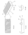
- FIGS. 2A-2B are views of a second comparative bone block-tendon assembly comprising two bone blocks that sandwich a tendon, the first bone block having a smooth tendon engaging surface while the second bone block has on its tendon engaging surface a saw-tooth pattern of ridges running perpendicular to the direction of pull of the tendon and the length of the bone block.
- FIG. 2A is an exploded view of the second comparative bone block assembly.
- FIG. 2B is a detailed view of the tendon and bone blocks from FIG. 2A . This saw-tooth pattern of ridges is angled to engage the tendon in its direction of pull. ( FIG. 6A ).
- This second comparative bone block-tendon assembly is tested for average load to failure (Newtons) in Table 1 relative to bone block-tendon assemblies of FIGS. 1 , 3 A- 3 B, 4 A- 4 D, and 5 A- 5 D, each having at least one different tendon engaging surface.
- FIGS. 3A-3B are views of a third comparative bone block-tendon assembly comprising two bone blocks that sandwich a tendon, each bone block having a textured (saw-tooth pattern) pattern ( FIG. 6A ) on its tendon engaging surface.
- FIG. 3A is an exploded view of the third comparative bone block assembly.
- FIG. 3B is a detailed view of the tendon and bone blocks from FIG. 3A .
- This third comparative bone block-tendon assembly is tested for average load to failure (Newtons) in Table 1 relative to bone block-tendon assemblies of FIGS. 1 , 2 A- 2 B, 4 A- 4 D, and 5 A- 5 D, each having at least one different tendon engaging surface.
- Newtons average load to failure
- FIGS. 4A-4D are views of a fourth comparative bone block-tendon assembly comprising two bone blocks that sandwich a tendon, the first bone block having a textured pattern (saw-tooth pattern of ridges) on its tendon engaging surface ( FIG. 6A ) while the second bone block is an intermediate bone block of the present invention having an a smooth tendon engaging (compressing) surface that is interrupted by two channels with rectangular cross-sections running the length of the bone block, which is in the direction of pull of the tendon.
- FIG. 4A is an exploded view of the fourth comparative bone block assembly.
- FIG. 4B is a side view of the assembled fourth comparative bone block assembly.
- FIG. 4C is an end view
- FIG. 4D is a detailed view of the tendon and bone blocks from FIG.
- This fourth comparative bone block-tendon assembly was tested for average load to failure (Newtons) in Table 1 relative to bone block-tendon assemblies of FIGS. 1 , 2 A- 2 B, 3 A- 3 B and 5 A- 5 D, each having at least one different tendon engaging surface.
- FIGS. 5A-5D are views of a fifth comparative bone block-tendon assembly comprising two bone blocks that sandwich a tendon, the first bone block having a textured (saw-tooth) pattern of ridges on its tendon engaging surface ( FIG. 6A ) while the second bone block is a preferred intermediate bone block of the present invention having an a smooth tendon engaging (compressing) surface that is interrupted by two channels with omega cross-sections running the length of the bone block ( FIG. 11A ), which is in the direction of pull of the tendon.
- FIG. 5A is an exploded view of the fifth comparative bone block assembly.
- FIG. 5B is a side view of the assembled fifth comparative bone block assembly.
- FIG. 5C is an end view FIG.
- FIG. 5D is a detailed view of the tendon and bone blocks from FIG. 5A showing the lengthwise channels having a rectangular cross-section in the intermediate bone block of the present invention.
- This fifth comparative bone block-tendon assembly was tested for average load to failure (Newtons) in Table 1 relative to bone block-tendon assemblies of FIGS. 1 , 2 A- 2 B, 3 A- 3 B, and 4 A- 4 D, each having at least one different tendon engaging surface.
- FIGS. 6A-6D show various views of the textured bone block used in the assemblies of FIGS. 2-5 , wherein the texture was a saw-tooth pattern of ridges on the tissue (e.g., tendon) engaging surface.
- FIG. 6A is a perspective view of the textured bone block.
- FIG. 6B is a top view of the textured bone block looking directly down at the saw-tooth pattern of ridges on the (soft) tissue engaging surface.
- FIG. 6C is a side view of the textured bone block showing the pattern of ridges appearing from this perspective as angled teeth on the tissue engaging surface.
- FIG. 6D is a detail view of the saw-tooth pattern as shown on the textured surface in FIG. 6C .
- FIGS. 7A-7D show various views of another embodiment of a textured bone block, wherein the texture is a pattern of ridges and valleys on the soft tissue (e.g., tendon) engaging surface.
- FIG. 7A is a perspective view of the textured bone block.
- FIG. 7B is a top view of the textured bone block looking directly down at the pattern.
- FIG. 7C is a side view of the textured bone block showing the pattern of ridges and valleys on the soft tissue (e.g., tendon) engaging surface.
- FIG. 7D is an end view of the textured bone block of FIG. 7A .
- FIGS. 8A-8D show various views of one embodiment of an intermediate bone block of the present invention having channels with a square cross section running across the intended direction of pull (arrow) of a segment of soft tissue (e.g., tendon).
- FIG. 8A is a perspective view of the intermediate bone block.
- FIG. 8B is a top view of the intermediate bone block looking directly down at the layout (pattern) of channels.
- FIG. 8C is a side view of the intermediate bone block showing the shape and pattern of cavities (e.g., channels) and tissue compressing surfaces.
- FIG. 8D is an end view of the intermediate bone block of FIG. 8A .
- FIGS. 9A-9D show various views of one embodiment of an intermediate bone block of the present invention having channels running across the intended direction of pull (arrow) of a segment of soft tissue (e.g., tendon).
- the channels are similar to those in FIGS. 8A-8D except that the bottom edges of the channels have a radius (R) edge.
- FIG. 9A is a perspective view of the intermediate bone block.
- FIG. 9B is a top view of the intermediate bone block looking directly down at the pattern of channels.
- FIG. 9C is a side view of the intermediate bone block showing the pattern of cavities (e.g., channels) and tissue compressing surfaces.
- FIG. 9D is an end view of the intermediate bone block of FIG. 9A .
- FIGS. 10A-10D show various views of another embodiment of an intermediate bone block of the present invention having channels with a “V” shaped cross section running across the intended direction of pull (arrow) of a segment of soft tissue (e.g., tendon).
- FIG. 10A is a perspective view of the intermediate bone block.
- FIG. 10B is a top view of the intermediate bone block looking directly down at the layout (pattern) of channels.
- FIG. 10C is a side view of the intermediate bone block showing the pattern of cavities (e.g., channels) and tissue compressing surfaces.
- FIG. 10D is an end view of the intermediate bone block of FIG. 10A .
- FIGS. 11A-11D show various views of one embodiment of an intermediate bone block of the present invention having channels with an omega-shaped cross section running substantially in the intended direction of pull (arrow) of a segment of soft tissue (e.g., tendon).
- FIG. 11A is a perspective view of one embodiment on an intermediate bone block having channels with an omega shaped cross section.
- FIG. 11B is a top view of the intermediate bone block looking directly down at the lengthwise pattern of channels.
- FIG. 11C is a side view of the intermediate bone block showing the pattern of cavities (e.g., parallel channels) and tissue compressing surfaces.
- FIG. 11D is an end view of the intermediate bone block of FIG. 11A . If the block of FIG. 11D is rotated 180° in the plane of the paper, the omega shape of channel 117 becomes more apparent.
- FIGS. 12A-12D show various views of another embodiment of an intermediate bone block of the present invention having a layout of channels with an omega-shaped cross section running substantially in the intended direction of pull (arrow) of a segment of soft tissue (e.g., tendon).
- the intermediate bone block of this embodiment differs from that shown in FIGS. 11A-11D because the present embodiment has a broken edge 128 .
- this reduction of the end of the tendon engaging face results in an internal leading edge configuration that reduces tissue stresses during assembly and use.
- FIG. 12A is a perspective view of one embodiment on an intermediate bone block having channels with an omega-shaped cross section.
- FIG. 12B is a top view of the intermediate bone block looking directly down at the substantially parallel layout of channels.
- FIG. 12C is a side view of the intermediate bone block showing the pattern of cavities (e.g., parallel channels) and tissue compressing surfaces.
- FIG. 12D is an end view of the intermediate bone block of FIG. 12A . If the block of FIG. 12D is rotated 180° in the plane of the paper, the omega shape of channel 127 becomes more apparent.
- FIGS. 13A-13D show various views of yet another embodiment of an intermediate bone block of the present invention having a layout of channels with an omega-shaped cross section running substantially across the intended direction of pull (arrow) of a segment of soft tissue (e.g., tendon).
- FIG. 13A is a perspective view of one embodiment on an intermediate bone block having channels with an omega-shaped cross section.
- FIG. 13B is a top view of the intermediate bone block looking directly down at the pattern of channels.
- FIG. 13C is a side view of the intermediate bone block showing the pattern of cavities (e.g., channels) and tissue compressing surfaces. If the block of FIG. 13C is rotated 180° in the plane of the paper, the omega shape of channel 137 becomes more apparent.
- FIG. 13D is an end view of the intermediate bone block of FIG. 13A .
- FIGS. 14A-14D show various views of yet another embodiment of an intermediate bone block of the present invention having a plurality of channels with different sized omega-shaped cross sections running substantially across the intended direction of pull (arrow) of a segment of soft tissue (e.g., tendon).
- FIG. 14A is a perspective view of this embodiment on an intermediate bone block.
- FIG. 14B is a top view of the intermediate bone block looking directly down at the pattern of channels.
- FIG. 14C is a side view of the intermediate bone block showing the pattern of cavities (e.g., channels) and tissue compressing surfaces. If the block of FIG. 14C is rotated 180° in the plane of the paper, the omega shape of each of different sized channels 147 A, 147 B and 147 C becomes more apparent.
- FIG. 14D is an end view of the intermediate bone block of FIG. 14A .
- FIGS. 15A-15D show various views of yet another embodiment of an intermediate bone block of the present invention having a layout of channels with an omega-shaped cross section running substantially across the intended direction of pull (arrow) of a segment of soft tissue (e.g., tendon) and channels with an omega-shaped cross section running substantially in the intended direction of pull (arrow) of a segment of soft tissue (e.g., tendon).
- FIG. 15A is a perspective view of one embodiment on an intermediate bone block having channels with an omega-shaped cross section.
- FIG. 15B is a top view of the intermediate bone block looking directly down at the criss-crossing pattern of channels.
- FIG. 15C is a side view of the intermediate bone block showing the pattern of cavities (e.g., channels) and tissue compressing surfaces.
- FIG. 15D is an end view of the intermediate bone block of FIG. 15E also showing the omega cross-section of the channels. If the views of FIGS. 15C and 15D are rotated 180° in the plane of the paper, the omega cross-sectional shape of channels 157 B and 157 A, respectively becomes more apparent.
- FIGS. 16A-16D show various views of yet another embodiment of an intermediate bone block of the present invention having a plurality of channels with omega-shaped cross sections running substantially across the intended direction of pull (arrow) of a segment of soft tissue (e.g., tendon).
- FIG. 16A is a perspective view of this embodiment on an intermediate bone block.
- FIG. 16B is a top view of the intermediate bone block looking directly down at the “V” shaped layout of the channels.
- FIG. 16C is a side view of the intermediate bone block showing the pattern of cavities (e.g., channels) and tissue compressing surfaces. If the block of FIG. 16 C is rotated 180° in the plane of the paper, the omega shape of the channels 167 becomes more apparent.
- FIG. 16D is an end view of the intermediate bone block of FIG. 16A .
- FIGS. 17A-17D show various views of a preferred embodiment of an intermediate bone block of the present invention having a plurality of channels with omega-shaped cross sections running substantially in the intended direction of pull (arrow) of a segment of soft tissue (e.g., tendon) and having a component that runs across the direction of intended pull of the segment of soft tissue.
- FIG. 17A is a perspective view of this embodiment on an intermediate bone block.
- FIG. 17B is a top view of the intermediate bone block of FIG. 17A looking directly down at the stacked triple “U” shaped (or double stacked “A”) layout of the channels.
- FIG. 17C is a side view of the intermediate bone block showing the pattern of cavities (e.g., channels) and tissue compressing surfaces. If the block of FIG. 17C is rotated 180° in the plane of the paper, the omega shape of the channels 177 becomes more apparent.
- FIG. 17D is an end view of the intermediate bone block of FIG. 17A .
- FIGS. 18A-18D show various views of one embodiment of an intermediate bone block of the present invention having channels with an omega-shaped cross section running substantially in the intended direction of pull (arrow) of a segment of soft tissue (e.g., tendon), and having a textured saw tooth pattern of ridges on the tissue engaging surface.
- FIG. 18A is a perspective view of this embodiment on an intermediate bone block showing the ridges on the soft tissue engaging surface angled to engage the soft issue in the direction of pull.
- FIG. 18B is a top view of the intermediate bone block looking directly down at the pattern of channels.
- FIG. 18C is a side view of the intermediate bone block showing the pattern of cavities (e.g., substantially parallel channels) and tissue compressing surfaces (ridges).
- FIG. 18D is an end view of the intermediate bone block of FIG. 18A . If the block of FIG. 18D is rotated 180° in the plane of the paper, the omega shape of channel 187 becomes more apparent.
- FIGS. 19A-19D show a series of views of the external profile of one embodiment of an intermediate bone block of the present invention.
- FIGS. 19A-19D are essentially views of the flip side of the intermediate bone block of FIGS. 11A-11D , respectively, wherein all outside edges were rounded to have a radius.
- FIG. 19A is a perspective view of one embodiment of an intermediate bone block wherein each outside edge (i.e., non-soft tissue contacting edge) is a radius edge.
- FIG. 19B is a top view of the intermediate bone block 190 of FIG. 19A , showing that all corners are rounded corners of a defined radius.
- FIG. 19C is a side view of the bone block 190 of FIG.
- FIG. 19A showing the radius edge R 1 and showing as a broken line the internal omega shaped channel running the length of the bone block.
- FIG. 19D is an end view of the intermediate bone block of FIG. 19A viewed from its end 194 and looking down the length of the two channels 197 having the omega (“ ⁇ ”) shaped cross section in upright configuration in this perspective.
- FIGS. 20A-20D show various views of a semi-capsule shaped embodiment of an intermediate bone block of the present invention having channels with an omega-shaped cross section running substantially in the intended direction of pull (arrow) of a segment of soft tissue (e.g., tendon).
- FIG. 20A is a perspective view of this embodiment on an intermediate bone block showing holes for receiving a biocompatible pin or other connector that would hold the depicted intermediate bone block to any one of a variety of appropriately shaped opposing bone blocks and a segment of soft tissue sandwiched therebetween.
- FIG. 20B is a top view of the soft tissue engaging face of this intermediate bone block looking directly down at the pattern of channels and pin holes.
- FIG. 20C is a side view of the intermediate bone block showing its semi-capsular shape.
- FIG. 20D is an end view of the intermediate bone block of FIG. 20A . If the block of FIG. 20D is rotated 180° in the plane of the paper, the omega shape of channel 207 becomes more apparent.
- FIGS. 21A-21D show various views of the exterior surface of a semi-capsule shaped embodiment of a bone block that can serve as the opposing bone block to the bone block of FIGS. 20A-20D .
- FIG. 21A is a perspective view of this embodiment of an opposing bone block showing holes for receiving a biocompatible pin or other connector (pin holes) that would hold this bone block to any one of a variety of appropriately shaped intermediate bone blocks (of the present invention) and to a segment of soft tissue sandwiched therebetween.
- FIG. 21B is a top view of the outside face of this opposing bone block looking directly down at its capsule shape and the position of the pin holes.
- FIG. 21C is a side view of the opposing bone block showing its semi-capsular shape.
- FIG. 21D is an end view of the opposing bone block of FIG. 21A .
- the bone block of FIG. 21A has channels on its tissue engaging surface (not shown), it becomes an intermediate bone block of the present invention.
- FIGS. 22A-22D show various views of the exterior profile of a semi-capsule shaped embodiment of an intermediate bone block of the present invention having channels with an omega-shaped cross section running substantially in the intended direction of pull (arrow) of a segment of soft tissue (e.g., tendon).
- this intermediate bone block may mate with the bone block of FIGS. 20A-20D or FIGS. 21A-21D .
- FIG. 22A is a perspective view of this embodiment on an intermediate bone block showing holes for receiving a biocompatible connector (e.g., pin or other connector) that would hold the depicted intermediate bone block to any one of a variety of appropriately shaped opposing bone blocks and a segment of soft tissue sandwiched therebetween.
- a biocompatible connector e.g., pin or other connector
- FIG. 22A also shows that the exterior surface has a curved notch or groove for maximizing engagement with an interference screw.
- FIG. 22B is a top view of this intermediate bone block looking directly down at the groove and pattern of pin holes.
- FIG. 22C is a side view of the intermediate bone block showing its semi-capsular shape.
- FIG. 22D is an end view of the intermediate bone block of FIG. 22A showing the groove having a radius R.
- FIGS. 23A-23D show views of yet another alternate embodiment for the exterior surface of an intermediate bone block of the invention.
- FIG. 23A is a perspective view of this embodiment of an opposing bone block showing holes for receiving a biocompatible connector, e.g., pin or other connector, (pin holes) that would hold this bone block to any one of a variety of appropriately shaped bone blocks and to a segment of soft tissue sandwiched therebetween. Also shown on the exterior surface of this embodiment are ridges suitable for gripping the bone tunnel and reducing slippage in the direction of pull (arrow) of the tendon.
- FIG. 23B is a top view of the outside face of this intermediate bone block looking directly down at its capsule shape and the position of the pin holes.
- FIG. 23A is a perspective view of this embodiment of an opposing bone block showing holes for receiving a biocompatible connector, e.g., pin or other connector, (pin holes) that would hold this bone block to any one of a variety of appropriately shaped bone blocks and to a segment of soft tissue sandwiched
- FIG. 23C is a side view of the opposing bone block showing its semi-capsular shape.
- FIG. 23D is an end view of the opposing bone block of FIG. 23A .
- the semi-capsule shaped intermediate bone block of FIG. 23A can mate with the bone block of FIG. 20A , 21 A, 22 A or preferably 23 A.
- FIGS. 24A-24D are various views of one embodiment of a BTB of the present invention.
- FIG. 24A is a perspective view of one embodiment of an assembled BTB of the present invention.
- the BTB is composed of two assembled bone block assemblies, one on each of the opposing ends of a segment of soft tissue. Each bone block assembly has at least one intermediate bone block of the present invention as a component thereof.
- FIG. 24B is a top view of the assembled BTB wherein one embodiment for positioning the bone pins is shown.
- FIG. 24C is a side view of the assembled BTB clearly showing the soft tissue (e.g., tendon) sandwiched between opposing bone blocks at each end.
- FIG. 24D is an end view of the assembled BTB clearly showing the soft tissue (e.g., tendon) sandwiched between opposing bone blocks at each end.
- FIGS. 25A-25D are views of another embodiment of a BTB of the present invention.
- FIG. 25A is an exploded perspective view of a preferred embodiment of an assembled BTB of the present invention.
- the BTB is composed of two assembled bone block assemblies, one on each of the opposing ends of a segment of soft tissue. Each bone block assembly has at least one intermediate bone block of the present invention as a component thereof.
- FIG. 25B is a top view of the assembled BTB wherein one embodiment for positioning the bone pins is shown.
- FIG. 25C is a side view of the assembled BTB clearly showing the soft tissue (e.g., tendon) sandwiched between opposing bone blocks at each end.
- FIG. 25A is an exploded perspective view of a preferred embodiment of an assembled BTB of the present invention.
- the BTB is composed of two assembled bone block assemblies, one on each of the opposing ends of a segment of soft tissue. Each bone block assembly has at least one intermediate bone block of the present invention as a component thereof.
- 25D is an end view of the assembled BTB clearly showing the soft tissue (e.g., tendon) sandwiched between opposing bone blocks at each end.
- the bone block-tissue assembly is generally cylindrical, having the approximate diameter of a bone tunnel into which it can be inserted, and a groove for maximizing contact with an interference screw.
- FIGS. 26A-26D are views of another embodiment of a BTB of the present invention.
- FIG. 26A is a perspective view of another embodiment of an assembled BTB of the invention.
- the soft tissue e.g., tendon
- FIG. 26B is a top view of the assembled BTB wherein only the soft tissue is visible
- FIG. 26C is cross-sectional side view CC of the assembled BTB clearly showing the soft tissue (e.g., tendon) sandwiched between opposing bone blocks at each end and the presence of the biocompatible bone pins.
- FIG. 26D is a side view of the assembled BTB clearly showing the soft tissue (e.g., tendon) sandwiched between opposing bone blocks at each end.
- FIGS. 27A-27D are views of another embodiment of a BTB of the present invention.
- FIG. 27A is a perspective view of the BTB of FIG. 26A further comprising a third bone block at each end sandwiching the soft tissue along the exterior of the bone blocks shown in FIG. 27A to produce a 5 layer sandwich assembly at each end comprising layers of bone:soft tissue:bone:soft tissue:bone.
- FIG. 27B is a top view of the assembled BTB wherein the assembly appears the same as in FIG. 24B .
- FIG. 27C is cross-sectional side view BB of the assembled BTB, clearly showing three bone blocks sandwiching two portions of the length of soft tissue (e.g., tendon) as those portions in turn sandwich the central bone block. The assembly is held together at each end by biocompatible pins or other connectors.
- FIG. 27D is a side view of the assembled BTB clearly showing the soft tissue (e.g., tendon) sandwiched between opposing bone blocks at each end.
- FIGS. 28A-28D are views of another embodiment of a BTB of the present invention comprising a 5 layer assembly at each end.
- FIG. 28A is a perspective view of a double tendon BTB comprising layers of bone:soft tissue:bone:soft tissue:bone.
- FIG. 28B is a top view of the assembled BTB wherein the assembly appears the same as in FIG. 24B .
- FIG. 28C is a side view of the assembled BTB, clearly showing three bone blocks sandwiching two distinct lengths of soft tissue (e.g., tendon) as those portions in turn sandwich the central bone block. The assembly is held together at each end by biocompatible pins or other connectors.
- FIG. 28D is an end view of the BTB of FIG. 28A .
- FIGS. 29A-29D are views of a dual tendon BTB that is a hybrid of FIGS. 28A and 24A insofar as the bone-tendon assembly at one end is a three layer sandwich and at the opposing end is a five layer sandwich.
- FIG. 29A is a perspective view of a double tendon BTB comprising 5 layers (bone:soft tissue:bone:soft tissue:bone) at one end and 3 layers (bone:soft tissue:bone) at the opposing end.
- FIG. 29B is a top view of the assembled BTB wherein the assembly appears substantially the same as in FIG. 24B .
- FIG. 29C is a side view of the assembled BTB, clearly showing three bone blocks sandwiching two distinct lengths of soft tissue (e.g., tendon) at one end and two bone blocks sandwiching a single length of soft tissue at the opposing end.
- the assembly is optionally held together at each end by 2-3 biocompatible connectors, e.g., pins or other mechanical connectors.
- FIG. 29D is an end view of the BTB of FIG. 29A .
- FIGS. 30A-30B are side and end views, respectively, of a harvested BTB 300 having a tendon 303 of a first defined length L 1 naturally attached at its first end to a first bone block and naturally attached at its second end to a second bone block.
- FIGS. 30C and 30D are side and end views, respectively, of 2 spacers for reducing the first defined length L 1 of tendon 303 to a shorter functional length L 2 , and optionally, 2 bone blocks for capping the tendon and providing for greater bone to bone contact between the graft and the a bone tunnel in a patient.
- 30E and 30F are side and end views, respectively, of an assembled bone block wherein the length L 1 of the tendon in a harvested BTB has been reduced to L 2 by assembling a spacer and an intermediate bone block of the invention to each of the naturally attached bone blocks.
- FIGS. 31A-31D are views of an alternate embodiment of an intermediate bone block of the present invention.
- FIG. 31A is a perspective view of one embodiment on an intermediate bone block having a sloped channel of uniform width.
- FIG. 31B is a top view of the intermediate bone block looking directly down at the central sloped channel.
- FIG. 31C is a side view of the intermediate bone block showing the slope of the central channel.
- FIG. 31D is an end view of the intermediate bone block of FIG. 31A looking up the sloping channel.
- FIGS. 32A-32D are views of an alternate embodiment of an intermediate bone block of the present invention.
- FIG. 32A is a perspective view of one embodiment on an intermediate bone block having a converging channel of substantially uniform depth.
- FIG. 31B is a top view of the intermediate bone block showing the channel converging from the opposing end.
- FIG. 31C is a side view of the intermediate bone block showing that the channel is of a substantially uniform depth.
- FIG. 31D is an end view of the intermediate bone block of FIG. 31A looking toward the converging channel at the opposing end.
- FIGS. 33A-33E are views of a template (jig or assembly fixture) used to assemble one end of a BTB (i.e., a bone block-tendon assembly).
- FIG. 33A is an exploded view of the template showing the upper and lower halves, the locking screws, and the holes for positioning the interference pins prior to impaling them into the templated bone:tendon:bone sandwich locked in position below.
- FIG. 33B is a perspective view of the assembled template which in this locked position would place a standard amount of tension on the pre-sized bone blocks and soft tissue placed therein prior to insertion of the interference pins.
- FIG. 33C is a top view of the assembled template.
- FIG. 33D is a front view of the assembled template showing opening 339 where the segment of soft tissue (e.g., tendon) would extend outside the device.
- FIG. 33E is a side view of the assembled template.
- FIGS. 34A-34D provide views of another embodiment of an assembled BTB of the present invention wherein a single segment of soft tissue (e.g., tendon or ligament) is doubled back to provide a double tendon BTB.
- FIG. 34A is a perspective view of the assembled BTB of this invention having an intermediate bone block 344 of the present invention sandwiching a tendon between an opposing bone block 346 .
- FIG. 34B is a top view of the BTB where the biocompatible connectors in the top of the opposing bone block are clearly visible.
- FIG. 34C is a side view showing tendon 343 doubling back on itself.
- FIG. 34D is view of the proximal end of the BTB in FIG. 34A , showing the bone blocks sandwiching the doubled up tendon.
- FIGS. 35A-35D provide views of another embodiment of an assembled BTB of the present invention wherein a single segment of soft tissue (e.g., tendon or ligament) is doubled back to provided a double tendon BTB.
- This embodiment is a variation of the embodiment of FIG. 34 but further includes two additional bone blocks at the two tendon end to sandwich the tendon and provide for bone to bone contact between the graft and the patient's bone when the graft is implanted in the surgically excised bone tunnel in the patient.
- FIG. 35A is a perspective view of the assembled BTB of this invention having an intermediate bone block 354 of the present invention sandwiching a tendon between an opposing bone block 356 .
- 35B is a top view of the BTB where the biocompatible connectors in the top of the opposing bone block-tendon assemblies are clearly visible.
- FIG. 35C is a side view showing tendon 353 doubling back on itself
- FIG. 35D is an end view of the BTB at the end where the two bone blocks sandwich the doubled up tendon.
- FIGS. 36A-36D are a series of views of another embodiment of an assembled BTB of the present invention.
- FIG. 36A is a perspective view of an assembled BTB comprising a length of soft tissue having opposing first and second ends, wherein the first and second ends, respectively, of the soft tissue are separately sandwiched between wedge shaped opposing bone blocks, the angle of the wedges being such that in combination, the wedges form a 3 dimensional shape whose opposing longitudinal surfaces are substantially parallel.
- the opposing faces of the bone blocks contain a lengthwise tapering profile.
- FIG. 36B is a top view of this embodiment of assembled BTB.
- FIG. 36C is a side view of this embodiment of assembled BTB showing the assembly details and the use of suitable biocompatible connectors.
- FIG. 36D is an end view of the proximal end of the assembled BTB as positioned in FIG. 36A .
- FIGS. 37A-37D show various views of the exterior profile of a preferred semi-capsule shaped embodiment of an intermediate bone block of the present invention having a saw-tooth pattern of striations 371 on the tissue (e.g., tendon) engaging surface.
- FIG. 37A is a top view of this embodiment of an intermediate bone block showing holes 372 A- 372 C for receiving a biocompatible pin or other connector that would hold the depicted intermediate bone block to any one of a variety of appropriately shaped opposing bone blocks and a segment of soft tissue sandwiched therebetween.
- FIG. 37B is a perspective view showing that the exterior surface of this embodiment of an intermediate bone block has a curved notch or groove 373 for maximizing engagement with an interference screw.
- FIG. 37C is a side view of the intermediate bone block showing its semi-capsular shape.
- FIG. 37D is an end view of the intermediate bone block of FIG. 37A .
- FIG. 37E is a detail view of the saw-tooth pattern as shown on the textured surfaces in FIGS. 37A-37D .
- FIGS. 38A-38D show various views of the exterior profile of another preferred semi-capsule shaped embodiment of an intermediate bone block of the present invention having a plurality of channels with omega-shaped cross sections running substantially in the intended direction of pull of a segment of soft tissue (e.g., tendon) and having a component that runs across the direction of intended pull of the segment of soft tissue.
- FIG. 38D is a top view of the intermediate bone block looking directly down at the stacked triple “U” shaped (or double stacked “A”) layout of the channels.
- FIG. 38C is a perspective view of this embodiment on an intermediate bone block showing a notch 384 cut out of the intermediate bone block.
- FIG. 38B is a side view of this embodiment of an intermediate bone block showing it semi-capsular shape.
- FIG. 38A is an end view of the intermediate bone block of FIG. 38D , in which the omega (“ ⁇ ”) shape of the channels 382 becomes more apparent.
- FIGS. 39A-39D provide views of another embodiment of an assembled BTB of the present invention wherein a single segment of soft tissue (e.g., tendon or ligament) 392 is gripped by a first bone block assembly at the first end of the BTB and is doubled back through a second bone block assembly 393 at the second end of the BTB to provide a double tendon BTB.
- FIG. 39A is a side view of the embodiment of a BTB.
- FIG. 39B is an end view of this embodiment of a BTB of the present invention as viewed looking from the tip of the bone block assembly 393 at the second end of the BTB.
- FIG. 39C is a side view of the embodiment of a BTB showing the top of bone block assembly 391 .
- FIG. 39D is a perspective view of this embodiment showing the second end of the soft tissue wrapped under the bottom of bone block assembly 391 .
- FIGS. 40A-40D provide views of an intermediate bone block of the present invention having a semi-capsular shape.
- FIG. 40A is a top view of the tissue engaging surface 403 of the intermediate bone block.
- FIG. 40B is a perspective view of this embodiment on an intermediate bone block showing a notch 405 cut out of the intermediate bone block.
- FIG. 40C is a side view showing the semi-capsular shape of the intermediate bone block.
- FIG. 40D is an end view of the intermediate bone block in which the “U” shape of the channel or groove becomes more apparent.
- FIGS. 41A-41D provide views of another embodiment of an assembled BTB of the present invention wherein the distal end of a single segment of soft tissue (e.g., tendon or ligament) 413 is gripped by a first bone block assembly 411 at the first end of the BTB and is doubled back through a second bone block 412 at the second end of the BTB to provide a double tendon BTB.
- FIG. 41A shows a side view of this embodiment.
- FIG. 41B shows an end view of this BTB embodiment.
- FIG. 41C is a top view of a BTB wherein portal 418 is shown through which the soft tissue passes.
- FIG. 41D is a perspective view showing soft tissue threaded through a portal in the bone block at the second end of a BTB and having the proximal end of the soft tissue wrap under the bone block assembly at the first end of the BTB.
- FIGS. 42A-42D provide views of one embodiment of an intermediate bone block.
- FIG. 42A is a top view of this embodiment.
- FIG. 42B is an end view of this embodiment.
- FIG. 42C is a side view of this embodiment.
- FIG. 42D is a perspective view of this embodiment.
- FIGS. 43A-43D provide views of one embodiment of an intermediate bone block.
- FIG. 43A is a top view of this embodiment.
- FIG. 43B is an end view of this embodiment.
- FIG. 43C is a side view of this embodiment.
- FIG. 43D is a perspective view of this embodiment.
- FIGS. 44A-44D provide views of one embodiment of an intermediate bone block.
- FIG. 44A is a top view of this embodiment.
- FIG. 44B is an end view of this embodiment.
- FIG. 44C is a side view of this embodiment.
- FIG. 44D is a perspective view of this embodiment.
- the present invention has multiple aspects.
- the present invention is directed to an intermediate bone block comprising a machined segment of cortical bone, cancellous bone, artificial bone or a combination thereof, the intermediate bone block having a face comprising one to ten compression surfaces and one to ten cavities, the compression surfaces suitable for compressing soft tissue, the one to ten cavities suitably sized for receiving uncompressed soft tissue and/or the compressed soft tissue that is being squeezed from adjacent compression surfaces.
- the bone block is cortical bone or cancellous bone or a combination thereof. More preferably, the bone block is cortical bone.
- the cavities are preferentially channels cut into the tendon engaging face of the bone blocks. Applicants discovered that the channels unexpectedly increase the grip of the tendon between the bone blocks. It is thought that the cavities (preferably, channels) capture uncompressed soft tissue (e.g., tendon) and the overflow of the adjacent compressed tissue allowing the compressive surfaces of the bone block to grab and hold the tissue rather than float on it. It was unexpectedly discovered that when the cross-sectional shape of the cavities is an omega shape, the maximum gripping of the tendon between the opposing bone blocks is achieved. It is believed that the omega shaped cross section advantageously captures and holds the uncompressed and overflow soft tissue.
- the omega shaped cavity (preferably, channel) has a narrower mouth than the body of the cavity (channel) because the tendon engaging face of the bone block is undercut.
- This feature allows the soft tissue to enter the cavity and expand in a direction opposite to the direction of the compressed soft tissue immediately above on the surface of the bone block.
- the rounded omega profile also eliminates stress concentrations and allows the soft tissue to expand and distribute the compressive load evenly across the entire cavity. This controlled expansion and even distribution of load occurs without compromising the internal structure and related natural properties of the soft tissue.
- the omega cavity gently grips the soft tissue without cutting, and prevents it from slipping, sliding or flowing in the direction it is being pulled or squeezed.
- the edge of the omega cavity only exerts force when needed in response to being pulled or squeezed.
- the narrow mouth of the omega cavity (or channel) on the bone block surface maximizes contact between the bone block surface (tendon engaging surface) and the tendon, and thus maximizes grip.
- the one to ten cavity(ies) have an undercut cross-sectional profile.
- undercut is meant that the cavities open up to be wider than their surface opening, much like a doorway opening into a wider room.
- Two examples of an “undercut cross-sectional profile” are an omega cross-sectional profile or a blunted triangular cross-sectional profile (like an opening for receiving a dovetail).
- An preferred cavity is a channel, more preferably a channel with an undercut profile, most preferably, a channel that has an omega cross-sectional profile.
- the intermediate bone block of the present invention has a plurality of uses and can be used with an identical bone block, a different bone block of the present invention, or a bone block of the prior art, to enhance the grip upon any soft tissue that engages its soft tissue (e.g., tendon) engaging surface.
- the intermediate bone block of the present invention is a versatile and functional component that can be combined with other components to form a plurality of different bone block assemblies suitable for binding to a soft tissue to form an implantable graft suitable for repair of a defect or injury in the body of a mammalian patient.
- a particularly preferred graft is a bone-tendon-bone graft. This graft is described in more detail below.
- the bone source for the intermediate bone block of the present invention is autograft, allograft, xenograft, or artificial bone. However, because the intermediate bone block is machined, it is typically allograft, xenograft, or artificial bone.
- the bone source is allograft or xenograft bone.
- the bone source is preferably human allograft bone.
- the bone source is preferably xenograft bone, and more preferably xenograft bone treated to reduce antigenicity and immune response.
- the soft tissue is typically a collagenous material that is autograft, allograft or xenograft.
- the soft tissue may be a natural or synthetic material.
- the soft tissue is a predetermined length of tendon, a bundle of tendons of the same or different lengths, a predetermined length of ligament, a bundle of ligaments of the same length or different lengths, a segment or segments of pericardium, dermis, fascia, dura, skin, submucosal tissue (e.g., intestinal tissue), cartilage, or a combination thereof.
- the source of the soft tissue is autograft, allograft, or xenograft.
- the source of the soft tissue is allograft or xenograft.
- the source is preferably human allograft.
- a tendon bundle comprising a xenograft tendon bundle or a combination of allograft and xenograft tendons of different thicknesses and lengths, provides for enhanced performance under extreme stresses. This combination is discussed further herein in relation to an assembled bone-tendon-bone implant of the present invention
- the surface is undercut with a ball mill to produce a cavity that has a greater interior width than the surface opening.
- the cavities with the omega cross section preferably run as one or more independent or intersecting channels on the soft tissue engaging surface of the intermediate bone block. See FIGS. 11-18 .
- the layout of one or more of the channels across the soft tissue-engaging surface is linear across the face of the intermediate bone block. See FIGS. 11A-11D .
- one or more of the channels is laid out to form a “V”-shaped channel (when viewed from above) across the soft tissue-engaging surface of the intermediate bone block. See FIGS. 16A-16D .
- the layout of channels can form a series of “V”s across the soft tissue-engaging surface.
- one of the omega channels is laid out as a W-shaped channel (when viewed from above) across the tissue-engaging surface of the intermediate bone block.
- the omega cross section can be made by precision milling parallel to the surface of the intermediate bone block with a ball shaped end mill, such that the tool removes some of the surface bone but primarily undercuts bone just below the surface. Such a tool is available from Dremel, Racine Wis.
- Another means for making the omega cross section is to use a router and the appropriate bit or bits. Because a router can be easily templated to switch directions, it is most convenient for laying out channels that switch directions across the face of the bone block, such as the “A,” “U,” “V” and “W” layout of channels having an omega cross section.
- the present invention is directed to a bone block assembly comprising an intermediate bone block of the present invention in combination with a second bone block.
- the second bone block can be the same or different than the intermediate bone block as the advantages of the present invention accrue from Applicants' intermediate bone block having an overflow cavity, as described herein, being present on a single bone block.
- the intermediate bone block and the second bone block are machined to receive 1 to 30 biocompatible connectors.
- these biocompatible connectors include any connectors capable of holding the intermediate bone block and the second bone block (i.e., the bone block assembly) together as a unit.
- the present invention is directed to a bone block assembly comprising a first intermediate bone block of the present invention in combination with 2-10 other bone blocks, providing bone block assemblies containing 3-10 bone blocks.
- the 2-10 other bone blocks can be the same or different than the first intermediate bone block as the advantages of the present invention accrue from an omega cavity being present on a single intermediate bone block.
- the 3-10 intermediate bone blocks can have various configurations for sandwiching soft tissue. See e.g. FIGS. 27 , 28 and 29 . In these bone block assemblies, the intermediate bone blocks are also machined to receive 1 to 30 biocompatible connectors.
- the present invention is directed to an assembled bone-tendon-bone (BTB) implant comprising a bone block assembly of the present invention affixed to one or both ends of a length or a bundle of soft tissue.
- BTB bone-tendon-bone
- the opposing end of soft tissue may be free (e.g., free tendon end) or the bone block at the second and opposing end of the soft tissue is a naturally occurring bone block or portion of bone.
- the bone block assemblies may be the same or different.
- the soft tissue is a length of tendon, a bundle of tendons of the same or different lengths, a length of ligament, a bundle of ligaments of the same length or different lengths, a segment or segments of pericardium, dermis or fascia, or a combination thereof.
- the soft tissue is a length of tendon or ligament or a bundle of tendons or ligaments of the same length or different lengths, or a combination thereof. It is also within the scope of the present invention that the tendons or ligaments or both in the bundles be of the same thickness or of different thicknesses. In the bundles, the tendons, or ligaments or both are allograft, xenograft, synthetic, artificial ligament scaffolds or a combination thereof. Preferably, the tendons are allograft or xenograft.
- the intermediate bone block, the second bone block or both may themselves be independently constructed from 1 to 30 bone portions, preferably from 1-10 bone portions, more preferably from 1 to 5 bone portions, even more preferably 1 to 3 bone portions, most preferably from 1 to 2 bone portions.
- the “T” component of the BTB is intended to refer to a length of tendon, a bundle of tendons of the same or different lengths, a length of ligament, a bundle of ligaments of the same length or different lengths, a segment or segments of pericardium, dermis, fascia, dura, skin, submucosal tissue (e.g. intestinal tissue), cartilage, or a combination thereof.
- Bundles refer to 1-10 discrete tendons or ligaments, which themselves can be made up of smaller fibers of tendons/ligaments that are stapled, glued, sutured, woven or braided.
- tendons or other soft tissues are crosslinked with a crosslinking agent.
- the segment of soft tissue is sufficiently large so that excess tissue extends beyond the end or sides of the bone block assembly. This excess soft tissue is useful for surgical placement and/or fixation.
- the “T” component or the BTB may also contemplate an engineered construct of natural or synthetic origin, such as a synthetic ligament repair scaffold, other flexible synthetic biomaterial, or specially formulated natural material such as that disclosed in the applicant's copending applications U.S. Ser. No. 10/754,310, entitled “Matrix Composition For Human Grafts/Implants” and filed Jan. 9, 2004, and in U.S. Ser. No. 10/793,976, entitled “Muscle-Based Grafts/Implants” and filed Mar. 5, 2004.
- Engineered constructs include, for example, processed collagen-based tissue matrix, such as the product sold under the trade name GraftJacket®, by Wright Medical Technology, Inc., Arlington, Tenn.
- the bone block assemblies may be the same or different.
- the soft tissue is a length of tendon, a bundle of tendons of the same or different lengths, a length of ligament, a bundle of ligaments of the same length or different lengths, a segment or segments of pericardium, dermis, fascia, dura, skin, submucosal tissue (e.g. intestinal tissue), cartilage, or a combination thereof.
- the soft tissue is a length of tendon or ligament or a bundle of tendons or ligaments of the same length or different lengths, or a combination thereof.
- the assembled BTB of the present invention can be tailored to the needs of the patient. For example, when two of the shorter ligaments stretch under strain to the length of one or more longer ligaments, the restraint posed by the longer ligaments engages and acts to stabilize the joint. See, e.g., FIG. 28A-D .
- a reconstructed tendon can have multiple fall back positions to stabilize a joint. This effect can also be achieved by utilizing assemblies that contain 3 or more bone blocks. See, e.g., FIGS. 28A-D & 29 A-D.
- multiple tendons can be designed to have multiple points of attachment or rotation, mimicking the structure and function of the multi-bundled native anterior cruciate ligament (ACL) construct.
- ACL anterior cruciate ligament
- Such construction is particularly useful for anterior cruciate reconstruction in a human knee joint.
- the tendons or ligaments or both in the bundles are of the same cross-sectional area or of different cross-sectional area.
- the tendons, or ligaments or both are allograft, xenograft or a combination thereof.
- the tendons are allograft.
- an entire BTB comprising a combination of allograft, xenograft, synthetic or artificial tissues offers advantages in strength, fixation, mechanical properties, biochemical properties, healing, design freedom and/or availability.
- a BTB is constructed of synthetic or allograft or autograft tendon, with a xenograft bone block assembly at one or both ends.
- a BTB is constructed of artificial or allograft bone with xenograft tendons.
- an allograft tendon is attached to a conventional bone block by a naturally occurring attachment at one end, and attached to a xenograft or artificial bone block assembly at the other end.
- a combination of allograft and xenograft tendons is assembled with a combination of allograft or xengraft or synthetic bone blocks.
- the intermediate bone block, the second bone block or both are independently constructed or assembled from 1 to 30 bone portions, preferably from 1-10 bone portions, more preferably from 1 to 5 bone portions, even more preferably from 1 to 3 bone portions, most preferably from 1 to 2 bone portions.
- the bone portions are cortical bone, cancellous bone, artificial bone or a combination thereof.
- the bone block portions are cortical bone, cancellous bone or a combination thereof. More preferably, the bone block portions are cortical bone. Typically, a majority of the bone portions are cortical bone.
- planks of cortical bone 1 mm in width are stacked right to left with their ends in the direction of pull of the tendon. With the planks being held in juxtaposition to one another, from 2 to 10 through holes of a predetermined diameter are precision drilled across the width of the 30 stacked planks. Typically, the width of the through holes is from about 1 mm to about 2 mm. Into each of the through holes is then inserted an appropriately shaped biocompatible connector that has an interference fit with the through-hole
- the bone block assemblies of the present invention are affixed to the end of a predetermined length of soft tissue (e.g., tendon) by 1 to 30 biocompatible connectors that engage each of the two opposing bone blocks and the tendon that is sandwiched therebetween.
- biocompatible connector includes but is not limited to a pin, screw, suture, staple, rivet, strap, nail, band, adhesive, or chemical cross linker.
- the biocompatible connector may be made from: metal, polymer, bone or other biologics including connective tissues. It is understood that when discussing sutures, adhesives, cross linkers, and other continuous or non-unitary biocompatible connectors, that a single application of the biocompatible connector type may contain multiple smaller units.
- a single suture connection can be fabricated by stitching a plurality of sutures, e.g., 10 to 100 small individual sutures, and a single adhesive connection may be made by applying a plurality of drops of adhesive, e.g., 10 to 100 small individual drops of adhesive.
- a suitable biocompatible connector is pin that is press fitted into a hole machined in the bone block.
- a typical pin is made from stainless steel, titanium, or cortical bone.
- a preferred pin is a cortical bone pin (i.e., a pin made from cortical bone).
- Interference fit cortical bone pins are preferred over the alternative biocompatible connector types listed above because they offer a strong and predictable fixation, are readily manufactured, incorporate and heal into the body, are simple to assemble, integrate easily into most graft designs and have minimal regulatory or safety risks.
- the target range for the pin in such an interference fit is 0.001 inches (0.0254 mm) to 0.003 inches (0.0762 mm) larger than the hole diameter, and is pressed fit into place.
- the pin is made from cortical bone, it has been learned that freeze-drying the bone pins and other bone pieces exerts a disproportionate shrinkage upon the pins compared to the hole diameters. That is, the pin shrinks slightly more than the hole shrinks. Uncorrected, this would result in a less accurate, and less acceptable, interference fit.
- a bone pin preferably of cortical bone, of a desired diameter is vacuum dried for at least five hours. This drying is preferably at room temperature and at a negative pressure of approximately 100 milliTorre. This pre-treatment results in a shrinkage of approximately 80 percent of the total shrinkage that would occur in freeze drying.
- the pin diameter is measured, and a hole is made in the portions to be assembled using an appropriately sized drill bit.
- the target size for the hole is 0.002 inches (0.0508 mm) to 0.0025 inches (0.0635 mm) smaller than the post-vacuum-drying pin diameter.
- the bone portions to be assembled have been kept saturated with moisture to maintain a consistent size and subsequent shrinkage percent.
- the pin(s) are press fitted into the through holes, machined into an intermediate bone block of the present invention (or into a second bone block), and then freeze dried.
- the resulting assembled allografts have been found to have interference fits in the desired target range. This method is applicable to the various embodiments described in this disclosure. Where the bone pins are not freeze dried, it is sufficient to dip them in alcohol to facilitate their insertion (press fitting).
- the bone block and soft tissue of the present invention must be treated to remove any antigenic proteins, which may generate a rejection of the implant. It also must be treated to remove any bacteria and viruses. Suitable processes for removing antigenic proteins and sterilizing to neutralize any bacteria and viruses are known in the art. See U.S. Pat. No. 5,846,484, entitled “Pressure flow system and method for treating a fluid permeable workpiece such as a bone,” which issued to Scarborough, et al. on Dec. 8, 1998.
- load to failure was the average of three measurements made on an Instron model 5800 force testing machine, Instron, Canton, Mass. and reflects the amount of force at which the bone block tendon assembly (BTA) failed to retain the tendon when the tendon was pulled opposite the direction of the bone block.
- BTA bone block tendon assembly
- a bone block of each of the BTAs of FIGS. 1-5 differed from the prior BTA in the Table solely in the characteristics of one of the tendon engaging surfaces of the two bone blocks that sandwiched the tendon therebetween.
- the BTA of FIG. 1 had two bone blocks wherein each had a smooth tendon engaging surface.
- FIG. 2A had one bone block with a smooth tendon engaging surface and a second bone block with a tendon engaging surface ( FIG. 6A ) that was textured with a saw tooth pattern (0.030 inch, or 0.76 mm teeth) that gripped opposite the direction of pull of the tendon.
- the BTA of FIG. 3A had both a first bone block and a second bone block each of which had a tendon engaging surface ( FIG. 6A ) that was textured with a saw tooth pattern (0.76 mm teeth) that gripped opposite the direction of pull of the tendon.
- FIGS. 5A-D had one bone block with a tendon engaging surface ( FIG. 11A ) of the present invention (i.e., having a channel with an omega cavity that ran in the direction of pull of the tendon) and a second bone block with a tendon engaging surface ( FIG. 6A ) that was textured with a saw tooth pattern (0.76 mm teeth) that gripped opposite the direction of pull of the tendon.
- FIG. 11A the BTA of FIGS. 5A-D had one bone block with a tendon engaging surface ( FIG. 11A ) of the present invention (i.e., having a channel with an omega cavity that ran in the direction of pull of the tendon) and a second bone block with a tendon engaging surface ( FIG. 6A ) that was textured with a saw tooth pattern (0.76 mm teeth) that gripped opposite the direction of pull of the tendon.
- Table 2 is compares the mean load to failure of five bone tendon assemblies as a function of the layout or configuration of channels (having an omega cross section) in five intermediate bone blocks of the present invention.
- Table 2 compares the mean load to failure of the various layouts as a function of the volume (mm 3 ) of bone block removed by creation of the channels.
- each of designs 01-05 was cut into the same size (10 mm ⁇ 5 mm ⁇ 25 mm) cortical bone block.
- the omega channels were cut with a 2.4 mm diameter ball end cutter, to a depth of 1.8 mm.
- the values for % Volume Removed were calculated based on the percentage of the machinable volume cut away, in this case defined by the maximum machinable depth of 1.8 mm.
- the opposing (cortical) bone blocks that were opposite each of designs 01-05 were substantially identical (to within manufacturing tolerances) and were the same length (25 mm), width (10 mm) and thickness (5 mm) as the bone blocks of designs 01-05.
- Each of the opposing bone blocks had the identical tendon engaging surface which was sawtooth.
- Substantially identical segments of allograft tendon were cut and sized prior to sandwiching between a design block (01-05) and an opposing bone block.
- bone block-tendon assemblies were made in triplicate and then tested. Testing was accomplished on an Instron Model 5800 force testing machine, Canton, Mass. by measuring the load to failure (N) for each bone block-tendon assembly. Failure occurred when the tendon was pulled free from the bone block assembly. The mean load to failure from the triplicate measurements was then calculated and reported in Table 2.
- design 02 inverted “U” layout
- design 04 (“A” shaped layout)
- A shaped layout
- Adding a second cross channel to design 04 to produce design 05 further increases the mean load to failure of the tendon in the bone block-tendon assembly by 5 N to 565 N.
- the decrease in surface area corresponded to a proportionally larger increase in percent volume removed.
- FIG. 1 is a view of a first comparative bone block-tendon assembly 10 comprising two bone blocks ( 1 and 2 ) that sandwich a tendon 3 , each bone block having a completely smooth (flat) tendon engaging surface.
- This first comparative bone block-tendon assembly 10 is tested for average load to failure (Newtons) in Table 1 relative to bone block-tendon assemblies of FIGS. 2-5 , each having at least one different tendon engaging surface.
- This bone block-tendon assembly 10 was made and comparatively tested for load strength relative to other substantially identical bone tendon assemblies that differed solely in their tendon engaging surfaces, this bone block-tendon assembly fared the worst and only had a mean load to failure of 260 N. See Table 1.
- FIGS. 2A-2B provide views of a second comparative bone block-tendon assembly 20 comprising two bone blocks ( 1 and 4 ) that sandwich a tendon 3 , the first bone block 1 having a smooth tendon engaging surface while the second bone block 4 has a saw tooth pattern or ridges on its tendon engaging surface.
- FIG. 2A is an exploded view of the second comparative bone block assembly.
- FIG. 2B is a detailed view of the tendon and bone blocks from FIG. 2A .
- this bone block-tendon assembly 20 had an average load to failure of 344N. See Table 1.
- substituting a bone block 4 having a saw tooth pattern of ridges as a textured surface for bone block 2 having a flat (smooth) surface increased the load required to induce failure of the resulting bone block tendon assembly 20 by 84 N (or by 32%) under these standardized conditions.
- FIG. 3 is a drawing of a third comparative bone block-tendon assembly comprising two bone blocks that sandwich a tendon, each bone block having a textured (saw-tooth pattern) pattern of ridges on its tendon engaging surface.
- This third comparative bone block-tendon assembly was made and tested for average load to failure (Newtons) in Table 1 relative to bone block-tendon assemblies of FIGS. 1 , 2 A- 2 B, 4 A- 4 B, and 5 A- 5 B, each having at least one different tendon engaging surface. Since substituting one of the flat tendon engaging surfaces of FIG. 1 with a textured (saw tooth pattern of ridges) tendon engaging surface as in FIG.
- FIG. 2 produced a 32% improvement in load until failure, one would have thought that substituting the remaining bone block with the flat tissue engaging surface of FIG. 2A with another bone block with a textured (saw tooth pattern of ridges) would have resulted in a bone block-tendon assembly with an increased the load at failure relative to the assembly of FIG. 2A .
- the resulting bone block-tendon assembly of FIG. 3A had an average load to failure of 343 N, and thus produced no improvement over the bone block-tendon assembly of FIG. 2A under these standardized conditions.
- FIGS. 4A-4D are views of a fourth comparative bone block-tendon assembly 40 comprising two bone blocks that sandwich a tendon 3 , the first bone block 4 having a textured pattern (saw-tooth pattern of ridges) on its tendon engaging surface (as for FIG. 3 ) while the second bone block 5 is an intermediate bone block of the present invention having an a smooth tendon engaging (compression) surface that is interrupted by two channels with rectangular cross-sections 6 running across the direction of pull of the tendon 3 .
- FIG. 4A is an exploded view of the fourth comparative bone block assembly.
- FIG. 4B is a side view of the assembled fourth comparative bone block assembly.
- FIG. 4C is an end view
- FIG. 4D is a detailed view of the tendon and bone blocks from FIG.
- FIGS. 4A-4D showing the lengthwise channels having a rectangular cross-section in the intermediate bone block of the present invention.
- This fourth comparative bone block-tendon assembly was made and tested for average failure load (Newtons) in Table 1 relative to bone block-tendon assemblies of FIGS. 1 , 2 A- 2 B, 3 A- 3 B and 5 A- 5 D, each having at least one different tendon engaging surface.
- the resulting bone block-tendon assembly 40 of FIGS. 4A-4D had an average load to failure of 426 N, and thus produced an 83 N (24%) improvement over the bone block-tendon assembly of FIG. 3A and a 166 N (64%) improvement over the bone block tendon assembly 10 of FIG. 1 under these standardized conditions.
- FIGS. 5A-5D are views of a fifth comparative bone block-tendon assembly 50 comprising two bone blocks ( 4 and 7 ) that sandwich a tendon 3 , the first bone block 4 having a textured pattern (saw-tooth pattern of ridges) on its tendon engaging surface while the second bone block 7 is a preferred intermediate bone block of the present invention having an a smooth tendon engaging (compression) surface that is interrupted by two channels 8 with omega cross-sections running in the direction of pull of the tendon 3 .
- FIG. 5A is an exploded view of the fifth comparative bone block assembly.
- FIG. 5B is a side view of the assembled fifth comparative bone block assembly.
- FIG. 5C is an end view.
- FIG. 5D is a detailed view of the tendon and bone blocks from FIG.
- FIGS. 5A-5D showing the lengthwise channels having a rectangular cross-section in the intermediate bone block of the present invention.
- This fifth comparative bone block-tendon assembly 50 was made and tested for average load to failure (Newtons) in Table 1 relative to bone block-tendon assemblies of FIGS. 1 , 2 A- 2 B, 3 A- 3 B, and 4 A- 4 D, each having at least one different tendon engaging surface.
- Newtons average load to failure
- just changing the shape of the two channels in the bone block-tendon assembly of FIGS. 4A-4D from having a rectangular to an omega cross section to produce the bone block tissue assembly of FIGS. 5A-5D resulted in a bone-block tendon assembly that would not fail until an average load of 516 N.
- the intermediate bone blocks of the present invention which are characterized by the interruption of the soft tissue (e.g., tendon) engaging surface of a bone block with 1-10 surface cavities, particularly channels, and particularly the channels with the undercut or omega cross section, provide enhanced gripping of a soft tissue (particularly a tendon) without tearing or cutting, in a bone block-tendon assembly, such as used in Applicants' assembled BTB.
- soft tissue e.g., tendon
- FIGS. 6A-6D show various views of the textured bone block 60 used in the assemblies of FIGS. 2-5 , wherein the texture was a saw-tooth pattern on the tissue (e.g., tendon) engaging surface.
- FIG. 6A is a perspective view of the textured bone block 60 , having opposing end walls 64 and 65 , side wall 63 , and showing rows of ridges 62 in a saw tooth pattern angled away from the direction of pull of the tendon (arrow).
- FIG. 6B is a top view of the textured bone block looking directly down at the saw-tooth pattern of ridges on the (soft) tissue engaging surface 61 .
- FIG. 6A is a perspective view of the textured bone block 60 , having opposing end walls 64 and 65 , side wall 63 , and showing rows of ridges 62 in a saw tooth pattern angled away from the direction of pull of the tendon (arrow).
- FIG. 6B is a top view of the textured bone block looking directly down at the saw
- FIG. 6C is a side view of the textured bone block showing the pattern of ridges 62 which look like angled teeth from this perspective.
- FIG. 6D is a blow-up of the details of the angled ridges shown in 6 D, having a height A and an attack angle B.
- FIGS. 7A-7D show various views of an alternative textured bone block 70 , wherein the texture is a pattern of ridges and valleys on the tendon engaging surface.
- FIG. 7A is a perspective view of the textured bone block 70 , having opposing end walls 74 and 75 , side wall 73 and a textured soft tissue engaging surface 71 .
- FIG. 7B is a top view of the textured bone block 70 looking directly down at the textured pattern on soft tissue engaging surface 71 .
- FIG. 7C is a side view of the textured bone block showing the pattern of mounds 76 and valleys 77 on the soft tissue (e.g., tendon) engaging surface 71 .
- FIG. 7D is an end view of the textured bone block of FIG.
- FIGS. 8A-8D show a series of views of one embodiment of an intermediate bone block of the present invention having channels 87 with a square cross section running substantially perpendicular to the length of the bone block 80 and the intended direction of pull (arrow) of a segment of soft tissue (e.g., tendon). Even if one direction if pull is indicated, it is within the scope of the present invention that the intermediate bone blocks be used in a bone block assembly in either lengthwise orientation (shown as a double headed arrow).
- FIG. 8A is a perspective view of the intermediate bone block 80 , having opposing end walls 84 and 85 , side wall 83 , and soft tissue engaging surface 81 .
- FIG. 8B is a top view of the intermediate bone block looking directly down at the layout (pattern) of channels 87 in tissue engaging surface 81 .
- FIG. 8C is a side view of the intermediate bone block showing the pattern of cavities (e.g., channels 87 ) with a square cross section and a plurality of tissue compression surfaces 86 bordering the channels 87 .
- the cross section of the channels is a square.
- a and B are not equal, such that the cross section of the channel 87 is a rectangle.
- FIG. 8D is a view of the intermediate bone block 80 of FIG. 8A viewed from end 84 .
- the size range in the intermediate bone blocks of the present invention are based upon the intended use of the bone block and in some instances the size of the patient.
- Typical sizes of the intermediate bone block range in length from 10 mm to 50 mm; in width from 2 mm to 15 mm; and in height or diameter from 2 mm to 15 mm.
- the length ranges from from 15 mm to 35 mm; more preferably from 20 mm to 25 mm.
- the width ranges from from 6 mm to 13 mm; more preferably from 9 mm to 12 mm.
- the height or diameter ranges from 6 mm to 13 mm; more preferably from 9 mm to 12 mm.
- FIGS. 9A-9D show views of another embodiment of an intermediate bone block of the present invention having a plurality of channels 97 running substantially perpendicular to the length of the bone block 90 and the intended direction of pull (arrow) of a segment of soft tissue (e.g., tendon).
- the plurality of channels 97 are similar to the channels 87 in FIGS. 8A-8D except that the bottom edges of the channels 97 have a radius (R) edge.
- FIG. 9A is a perspective view of the intermediate bone block 90 , having opposing end walls 94 and 95 , side wall 93 , and soft tissue engaging surface 91 .
- FIG. 9B is a top view of the intermediate bone block 90 looking directly on soft tissue engaging surface 91 , which is characterized by a plurality of channels 97 interrupting the surface and leaving a plurality of isolated soft tissue compression surfaces 96 .
- FIG. 9C is a side view of the intermediate bone block showing the pattern of cavities (e.g., channels 97 ) and tissue compression surfaces 96 .
- the cross section of the channels 97 is shown as square with rounded edges (i.e., a rounded square).
- the depth B of the channel 97 equals its width A.
- a and B are not equal, such that the cross section of the channel 97 is a rectangle.
- FIG. 9D is a view of the intermediate bone block 90 of FIG. 9A viewed from end 94 .
- FIGS. 10A-10D show a series of views of another embodiment of an intermediate bone block of the present invention having a plurality of channels 107 running substantially perpendicular to the length of the bone block 100 and the intended direction of pull (arrow) of a segment of soft tissue (e.g., tendon).
- the plurality of channels 107 have a triangular cross section.
- FIG. 10A is a perspective view of the intermediate bone block 100 , having opposing end walls 104 and 105 , side wall 103 , and soft tissue engaging surface 101 .
- the soft tissue engaging surface 101 is broken up by a series of channels 107 having a triangular (“V” shaped) cross section, leaving a plurality of isolated tissue compression surfaces 106 .
- V triangular
- FIG. 10B is a top view of the intermediate bone block 100 looking directly on soft tissue engaging surface 101 , which is characterized by a plurality of channels 107 interrupting the surface and leaving a plurality of isolated soft tissue compression surfaces 106 .
- FIG. 10C is a side view of the intermediate bone block showing the pattern of cavities (e.g., channels 107 ) and tissue compression surfaces 106 .
- the cross section of the channels 107 is shown as triangular. In this embodiment as shown, the channel has a depth B and an angle A at its tip. While the triangular channel is shown as equilateral, it is also within the scope of the present invention that the side walls of the triangle not be equal.
- FIG. 10D is a view of the intermediate bone block 100 of FIG. 10A viewed from end 104 .
- FIGS. 11A-11D show a series of views of one preferred embodiment of an intermediate bone block of the present invention as used in the test block of FIG. 5 and Table 1.
- FIG. 11A is a perspective view of one embodiment on an intermediate bone block 110 having opposing end walls 114 and 115 , side wall 113 , and two channels 117 with an (inverted) omega-shaped cross section running the length of the bone block and substantially in the intended direction of pull (arrow) of a segment of soft tissue (e.g., tendon).
- the two channels 116 are surrounded by soft tissue compression surfaces 116 .
- FIG. 11B is a top view of the intermediate bone block looking directly down on soft tissue engaging surface 111 , having two channels 117 surrounded by soft tissue compression surfaces 116 .
- FIG. 11A is a perspective view of one embodiment on an intermediate bone block 110 having opposing end walls 114 and 115 , side wall 113 , and two channels 117 with an (inverted) omega-shaped cross section running the length of the bone block and substantially in
- FIG. 11C is a side view of the intermediate bone block 110 , showing that the channels have a substantially uniform depth. However, it is also within the scope of the present invention that the channels 117 have a slope (as also shown elsewhere) between opposing ends 114 and 115 , or have incremental changes in depth.
- FIG. 11D is an end view of the intermediate bone block 110 viewed from end 114 , showing the cross sectional (omega) shape of the channels 117 . If the block of FIG. 11D is rotated 180° in the plane of the paper, the omega (“ ⁇ ”) shape of channel 117 becomes more apparent.
- FIGS. 12A-12D show a series of views of one preferred embodiment of an intermediate bone block of the present invention.
- FIG. 12A is a perspective view of one embodiment on an intermediate bone block 120 having opposing end walls 124 and 125 , side wall 123 , and two channels 127 with an omega-shaped cross section running the length of the bone block and substantially in the intended direction of pull (arrow) of a segment of soft tissue (e.g., tendon).
- the two channels 126 are surrounded by soft tissue compression surfaces 126 .
- End 124 which is the end from which the soft tissue (e.g., tendon) would extend and be pulled has a radius curve 128 to minimize any sharp edge that could cut into the tendon or fray its edges.
- FIG. 12B is a top view of the intermediate bone block looking directly down on soft tissue engaging surface 121 , having two channels 127 surrounded by soft tissue compression surfaces 126 .
- FIG. 12C is a side view of the intermediate bone block 120 , showing that the channels have a substantially uniform depth. However, it is also within the scope of the present invention that the channels 127 have a slope (as also shown elsewhere) between opposing ends 124 and 125 , or have incremental changes in depth.
- FIG. 12D is an end view of the intermediate bone block 120 viewed from end 124 , showing the cross sectional (omega) shape of the channels 127 . If the block of FIG. 12D is rotated 180° in the plane of the paper, the omega (“ ⁇ ”) shape of channel 127 becomes more apparent.
- FIGS. 13A-13D show a series of views of one embodiment of an intermediate bone block of the present invention having channels 137 with an omega shaped cross section running substantially perpendicular to the length of the bone block 130 and the intended direction of pull (arrow) of a segment of soft tissue (e.g., tendon).
- FIG. 13A is a perspective view of the intermediate bone block 130 , having opposing end walls 134 and 135 , side wall 133 , and soft tissue engaging surface 131 .
- the soft tissue engaging surface 131 is broken up by a series of channels 137 having an omega shaped square cross section, leaving a plurality of isolated tissue compression surfaces 136 .
- FIG. 13B is a top view of the intermediate bone block looking directly down at the layout (pattern) of channels 137 cut into tissue engaging surface 131 , leaving four soft tissue compression surfaces separated by the channels.
- FIG. 13C is a side view of the intermediate bone block showing the omega cross-sectional shape of the channels. More particularly, when the block of FIG. 13C is rotated 180° in the plane of the paper, the omega (“ ⁇ ”) shape of channel 137 becomes more apparent.
- FIG. 13D is a view of the intermediate bone block 130 of FIG. 13A viewed from end 134 .
- FIGS. 14A-14D show various views of yet another embodiment of an intermediate bone block of the present invention having a plurality of channels with different sized omega-shaped cross sections running substantially perpendicular to the length of the bone block 140 and the intended direction of pull (arrow) of a segment of soft tissue (e.g., tendon).
- this bone block which has an asymmetrical layout of channels may have the segment of soft tissue pull in either direction.
- FIG. 14A is a perspective view of this embodiment on an intermediate bone block, having opposing ends 144 and 145 , side 143 , tissue engaging surface 141 that is broken up by three different sized channels ( 147 A, 147 B and 147 C) with omega shaped cross sections, leaving four soft tissue compression surfaces.
- FIG. 14A is a perspective view of this embodiment on an intermediate bone block, having opposing ends 144 and 145 , side 143 , tissue engaging surface 141 that is broken up by three different sized channels ( 147 A, 147 B and 147 C) with omega shaped cross sections,
- FIG. 14B is a top view of the intermediate bone block looking directly down at the pattern of channels.
- FIG. 14C is a side view of the intermediate bone block, showing the pattern of cavities (e.g., channels) and tissue compression surfaces. If the block of FIG. 14C is rotated 180° in the plane of the paper, the omega shape of each of different sized channels 147 A, 147 B and 147 C become apparent.
- FIG. 14D is an end view of the intermediate bone block of FIG. 14A as viewed from end 144 .
- FIGS. 15A-15D show various views of yet another embodiment of an intermediate bone block of the present invention.
- FIG. 15A is a perspective view of one embodiment on an intermediate bone block 150 , having opposing ends 154 and 155 , sidewall 153 running the length of the bone block 150 , soft tissue engaging surface 151 that is broken up by a layout of channels 157 B with an (inverted) omega-shaped cross section running substantially perpendicular to the length of the bone block 150 across the intended direction of pull (arrow) of a segment of soft tissue (e.g., tendon) and more channels 157 A with an (inverted) omega-shaped cross section running substantially in the intended direction of pull (arrow) of a segment of soft tissue (e.g., tendon).
- channels 157 B with an (inverted) omega-shaped cross section running substantially perpendicular to the length of the bone block 150 across the intended direction of pull (arrow) of a segment of soft tissue (e.g., tendon)
- channels 157 A with an (inverted) omega-
- FIG. 15B is a top view of the intermediate bone block looking directly down at tissue engaging surface 151 having criss-crossing channels 157 A and 157 B producing a waffle pattern of plateaus of tissue compression surfaces 156 .
- FIG. 15C is a side view of the intermediate bone block showing the pattern of cavities (e.g., channels) 157 B with the omega shaped cross section.
- FIG. 15D is an end view of the intermediate bone block of FIG. 15A also showing a lengthwise view of channels 157 A having the omega shaped cross-section. If the views of FIGS. 15C and 15D are rotated 180° in the plane of the paper, the omega cross-sectional shape of channels 157 B and 157 A, respectively becomes more apparent.
- FIGS. 16A-16D show various views of yet another embodiment of an intermediate bone block of the present invention having a plurality of channels with omega-shaped cross sections running generally widthwise and across the intended direction of pull (arrow) of a segment of soft tissue (e.g., tendon).
- FIG. 16A is a perspective view of intermediate bone block 160 , having opposing ends 164 and 165 , sidewall 163 running the length of the bone block 160 , soft tissue engaging surface 161 that is broken up by a “V” shaped layout of channels 167 with an (inverted) omega-shaped cross section running substantially across the intended direction of pull (arrow) of a segment of soft tissue (e.g., tendon).
- FIG. 16B is a top view of the intermediate bone block looking directly down at tissue engaging surface 161 having a “V” shaped layout of four channels 167 cut therein, leaving a plurality of tissue compression surfaces 166 .
- FIG. 16C is a side view of the intermediate bone block showing the (inverted) omega cross sectional shape of the channels 167 . If the block of FIG. 16C is rotated 180° in the plane of the paper, the omega (“ ⁇ ”) shape of the channels 167 becomes more apparent.
- FIG. 16D is an end view of the intermediate bone block 160 of FIG. 16A viewed from end 164 .
- FIGS. 17A-17D show a series of views of a more preferred embodiment of an intermediate bone block of the present invention.
- FIG. 17A is a perspective view of intermediate bone block 170 , having opposing ends 174 and 175 , sidewall 173 running the length of the bone block 170 , soft tissue engaging surface 171 that is broken up by a stacked/overlapping double “A” (or stacked or overlapping triple “U”) pattern of channels 177 (as tested in Table 2).
- the layout of the channels has a first component that runs lengthwise parallel wall 173 and in the intended direction of pull (arrow) of a segment of soft tissue (e.g., tendon), and a second component that runs widthwise and/or across the intended direction of pull of the tendon.
- FIG. 17A is a top view of the intermediate bone block looking directly down at the triple “U” shaped layout of the channels.
- FIG. 17C is a side view of the intermediate bone block showing the pattern of cavities (e.g., channels) and tissue compression surfaces. If the block of FIG. 17C is rotated 180° in the plane of the paper, the omega (“ ⁇ ”) shape of the channels 177 becomes apparent.
- FIG. 17D is an end view of the intermediate bone block of FIG. 17A .
- FIGS. 18A-18D show a series of views of another embodiment of an intermediate bone block of the present invention.
- This embodiment is essentially the intermediate bone block of FIGS. 11A-11B that is modified to have as its tendon engaging surface the textured surface of FIGS. 6A-6C .
- Other textured surfaces can be utilized in the same manner as the tendon engaging surface, e.g., that shown in FIGS. 7A-7D .
- FIG. 7A-7D shows a series of views of another embodiment of an intermediate bone block of the present invention.
- This embodiment is essentially the intermediate bone block of FIGS. 11A-11B that is modified to have as its tendon engaging surface the textured surface of FIGS. 6A-6C .
- Other textured surfaces can be utilized in the same manner as the tendon engaging surface, e.g., that shown in FIGS. 7A-7D .
- FIG. 18A is a perspective view of intermediate bone block 180 , having opposing ends 184 and 185 , sidewall 183 running the length of the bone block 180 , soft tissue engaging surface 181 having rows of ridges 189 angled to engage the soft issue in the direction of pull of the tendon, the soft tissue engaging surface being broken up by two channels 187 cut therein, the channels running the length of the bone block 180 and having an (inverted) omega-shaped cross section.
- FIG. 18B is a top view of the intermediate bone block 180 looking directly down at tissue engaging surface 181 and the two substantially parallel channels 187 cut therein, leaving three textured soft tissue compression surfaces 186 .
- FIG. 18A is a perspective view of intermediate bone block 180 , having opposing ends 184 and 185 , sidewall 183 running the length of the bone block 180 , soft tissue engaging surface 181 having rows of ridges 189 angled to engage the soft issue in the direction of pull of the tendon, the soft tissue engaging surface being broken up by two channels 187 cut therein, the
- FIG. 18C is a side view of the intermediate bone block showing the saw tooth pattern of angled ridges 189 appearing as angled teeth in this perspective.
- FIG. 18D is an end view of the intermediate bone block of FIG. 18A viewed from end 184 , showing the omega shaped cross section of channels 187 . If the block of FIG. 18D is rotated 180° in the plane of the paper, the omega (“ ⁇ ”) shape of each of channels 187 becomes more apparent.
- FIGS. 19A-19D show a series of views of the external profile of one embodiment of an intermediate bone block of the present invention.
- FIGS. 19A-19D are essentially views of the flip side of the intermediate bone block of FIG. 11A-11D , respectively, wherein all outside edges were rounded to have a radius.
- FIG. 19A is a perspective view of intermediate bone block 190 , having opposing ends 194 and 195 each with a radius edge 199 of radius R 1 , sidewall 193 extending the length of the bone block 190 and having radius edge 198 of radius R 2 .
- the radius R 1 typically ranges from 0.5 mm to 5 mm.
- the radius R 2 typically ranges from 0.5 mm to 5 mm.
- FIG. 19B is a top view of the intermediate bone block 190 of FIG. 19A , showing an exterior surface 196 opposite the tissue engaging surface 191 (not shown) and radius edges 198 and 199 .
- FIG. 19C is a side view of the bone block 190 of FIG. 19A showing the outside corners having a rounded edge of radius R 1 , and showing as a broken line the internal omega shaped channel running the length of the bone block.
- FIG. 19D is an end view of the intermediate bone block of FIG. 19A viewed from its end 194 and looking down the length of the two channels 197 having the omega (“ ⁇ ”) shaped cross section in upright form in this perspective.
- Alternative embodiments of shapes for the outer surface of the intermediate bone block or bone block assembly include but are not limited to polygonal, cylindrical, threaded, bulleted, chamfered, angled, ridged, capsule shaped, tapered or a combination thereof.
- FIGS. 20A-20D show a series of views of one embodiment for the exterior shape of an intermediate bone block of the present invention. This embodiment essentially superimposes a capsule shape on the intermediate bone block of FIGS. 11A-11D .
- FIG. 20A is a perspective view of capsule shaped intermediate bone block 200 , having soft tissue (e.g. tendon) engaging surface 201 with two channels 207 cut therein and running the length of the capsule, the channels 207 having in this view an (inverted) omega-shaped cross section.
- Soft tissue engaging surface 201 also has three soft tissue compression surfaces 206 that are interrupted by two holes 202 , sized and placed for receiving a pin (not shown) that would engage and penetrate any soft tissue thereon and any opposing bone block face thereon.
- any of the capsule shaped intermediate bone blocks of the present invention typically range from 10 mm to 50 mm, more typically from 15 mm to 35 mm, preferably from 20 mm to 25 mm.
- FIG. 20B is a top view of the soft tissue engaging face 201 of the intermediate bone block 200 looking directly down at the pattern of channels 207 and pin holes 202 .
- the undercut nature of the omega channels is seen as the broken lines running parallel channels 207 .
- This view also shows the capsular shape of the bone block which facilitates its introduction into a bone tunnel in a patient to be treated.
- Each of the ends of the bone block have a first radius R 1 .
- the radius R 1 ranges from 3 mm to 10 mm.
- the radius R 1 may be defined such that it creates a full round across the entire end of the bone block.
- Each of the ends of the bone block have a second radius R 2 .
- the radius R 2 ranges from 3 mm to 10 mm.
- the radius R 2 may be defined such that it creates a full round across the entire end of the bone block assembly when assembled with another bone block having similar external geometry.
- the body of the cylinder has a radius R 3 .
- Typical dimensions of a circular surgical bone tunnel have a diameter of between about 7 mm and 12 mm.
- a typical diameter (2 ⁇ R 3 ) of the semi capsular bone block 200 is from about 7 mm to about 12 mm, respectively or slightly smaller.
- FIG. 20C is a side view of the intermediate bone block 200 showing another view of its semi-capsular shape. In this perspective, which is rotated 90° along the long axis of the capsule in FIG.
- FIG. 20D is an end view of the intermediate bone block of FIG. 20A . If the block of FIG. 20D is rotated 180° in the plane of the paper, the omega shape (“ ⁇ ”) of channel 207 becomes more apparent.
- FIGS. 21A-21D show various views of the exterior surface of a semi-capsule shaped embodiment of a bone block.
- the semi-capsular bone block of FIGS. 21A-21D can serve as the opposing bone block to the bone block of FIGS. 20A-20D .
- FIG. 21A is a perspective view of semi capsular bone block 210 showing holes 212 for receiving a biocompatible pin (not shown) that would hold this bone block to any one of a variety of appropriately shaped intermediate bone blocks (of the present invention) and to a segment of soft tissue sandwiched therebetween.
- FIG. 21B is a top view of the outside face of this opposing bone block looking directly down at its capsule shape, having ends with radius R 1 and holes 212 for receiving an interference pin.
- the radius R 1 typically ranges from 3 mm to 10 mm. Alternatively, the radius R 1 may be defined such that it creates a full round across the entire end of the bone block. Each of the ends of the bone block have a second radius R 2 . The radius R 2 ranges from 3 mm to 10 mm. Alternatively, the radius R 2 may be defined such that it creates a full round across the entire end of the bone block assembly when assembled with another bone block having similar external geometry.
- the body of the cylinder has a radius R 3 . Typical dimensions of a circular surgical bone tunnel have a diameter of between about 7 mm and 12 mm.
- a typical diameter (2 ⁇ R 3 ) of the semi capsular bone block 210 is from about 7 mm to about 12 mm, respectively or slightly smaller.
- Different combinations of radius values for R 1 , R 2 , and R 3 will result in tangent, truncated, or sharp corner edge transitions between the end of the bone block and the body of the bone block, e.g., 7 mm diameter bone block with a 10 mm R 1 will produce a sharp edge or corner between the body and the end as seen in FIG. 21B , while a 10 mm diameter bone block with a 5 mm R 1 will produce a tangent edge between the end of the bone block and the body of the bone block.
- FIG. 21C is a side view of the opposing bone block 210 showing its semi-capsular shape. In this perspective, which is rotated 90° along the long axis of the capsule in FIG. 21B , the radius at each end remains R 1 as in FIG. 21B .
- FIG. 21D is an end view of the opposing bone block of FIG. 21A .
- the bone block of FIG. 21A has channels (not shown) on its tissue engaging surface 211 , it becomes an intermediate bone block of the present invention.
- the opposing bone block 210 is shown with a flat tissue engaging surface 211 .
- the opposing bone block to any of Applicants' intermediate bone blocks
- the opposing bone block also have a textured surface, two of which are exemplified in FIGS. 6A-6C and 7 A- 7 D.
- FIGS. 22A-22D show a series of views of an embodiment of the exterior profile of an intermediate bone block of the present invention.
- FIG. 22A is a perspective view of the exterior surface of intermediate bone block 220 , which is analogous to the intermediate bone block of FIGS. 20A-20D , except that intermediate bone block 220 has a longitudinal groove 229 running its length.
- Groove 229 has radius R, which is suitable for maximizing radial contact with an interference screw (not shown).
- Groove 229 also has two holes 222 positioned thereon and suitably sized for receiving an interference pin (not shown) which would hold intermediate bone block 220 to a suitably sized opposing bone block (e.g., 200 or 210 ) and a segment of soft tissue sandwiched therebetween.
- FIG. 22B is a top view of intermediate bone block 220 looking directly down at its capsular shape from this perspective, having opposing ends with a radius R 1 , centrally positioned groove 229 , and the two symmetrically placed pin holes 222 in the groove 229 .
- the groove is positioned off center.
- the radius R 1 typically ranges from 3 mm to 10 mm.
- the radius R 1 may be defined such that it creates a full round across the entire end of the bone block.
- Each of the ends of the bone block have a second radius R 2 .
- the radius R 2 ranges from 3 mm to 10 mm.
- the radius R 2 may be defined such that it creates a full round across the entire end of the bone block assembly when assembled with another bone block having similar external geometry.
- the body of the cylinder has a radius R 3 .
- Typical dimensions of a circular surgical bone tunnel have a diameter of between about 7 mm and 12 mm.
- a typical diameter (2 ⁇ R 3 ) of the semi capsular bone block 220 is from about 7 mm to about 12 mm, respectively or slightly smaller.
- FIG. 22C is a side view of the intermediate bone block showing its semi-capsular shape and the positions of the holes 222 running through to tissue engaging surface 221 .
- FIG. 22D is an end view of the intermediate bone block of FIG.
- an intermediate bone block has 1 such groove for an interference screw, alternatively an intermediate bone block can have 2 to 6 such grooves, resulting in final bone block assemblies with grooves to accommodate from 1 to 12 interference screws, preferably 1 to 6 interference screws, more preferably 2 to 4 interference screws.
- Grooves for interference screws have threads, tapped threads or no threads.
- grooves for interference screws are specifically not included (e.g., when other fixation methods are used).
- a same or similar groove is included in the design to accommodate soft tissue that is external to the bone block assembly. Looking longitudinally down the capsular shape, there is a pair of channels 22 having an omega shaped cross section. In practice, this intermediate bone block may serve as the opposing bone block for the bone blocks of FIGS. 20A-20D or FIGS. 21A-21D .
- FIGS. 23A-23D show views of an alternate embodiment for the exterior surface of an intermediate bone block 230 of the present invention.
- Intermediate bone block 230 is semi-capsule shaped bone block that can be combined with the opposing bone block of FIGS. 20A-20D , 21 A- 21 D, 22 A- 22 D or itself 23 A- 23 D.
- FIG. 23A is a perspective view of semi-capsule shaped intermediate bone block 230 , having rounded opposing ends of radius R 1 , holes 232 for receiving a biocompatible pin (not shown) that would hold this bone block to any one of a variety of appropriately shaped intermediate bone blocks and to a segment of soft tissue sandwiched therebetween.
- FIG. 23B is a top view of the outside face of this intermediate bone block 230 looking directly down at its capsule shape (from this perspective) and the position of the pin holes 232 .
- the hemispherical ends have radius R 1 , and the ridges project at an angle “C”. The angle C ranges from 1° to 60°.
- the radius R 1 typically ranges from 3 mm to 10 mm. Alternatively, the radius R 1 may be defined such that it creates a full round across the entire end of the bone block. Each of the ends of the bone block have a second radius R 2 . The radius R 2 ranges from 3 mm to 10 mm. Alternatively, the radius R 2 may be defined such that it creates a full round across the entire end of the bone block assembly when assembled with another bone block having similar external geometry.
- the body of the cylinder has a radius R 3 . Typical dimensions of a circular surgical bone tunnel have a diameter of between about 7 mm and 12 mm.
- a typical diameter (2 ⁇ R 3 ) of the semi capsular bone block 230 is from about 7 mm to about 12 mm, respectively or slightly smaller.
- Different combinations of radius values for R 1 , R 2 , and R 3 will result in tangent, truncated, or sharp corner edge transitions between the end of the bone block and the body of the bone block, e.g., 7 mm diameter bone block with a 10 mm R 1 will produce a sharp edge or corner between the body and the end as seen in FIG. 23B , while a 10 mm diameter bone block with a 5 mm R 1 will produce a tangent edge between the end of the bone block and the body of the bone block.
- FIG. 23C is a side view of the intermediate bone block 230 showing its semi-capsular shape and channel 237 running its length.
- FIG. 23D is an end view of the intermediate bone block 230 , showing the generally hemispherical shape of radius R 1 .
- the radius R 1 ranges from 3 mm to 10 mm.
- this intermediate bone block may be combined with the bone block of FIG. 20A , FIG. 21A , FIG. 22A or preferably FIG. 23A .
- FIGS. 24A-D are views of one embodiment of a BTB of the present invention, defined as a length of soft tissue (e.g., typically tendon or ligament) having opposing ends and a bone block-tendon assembly at each of the opposing ends.
- FIG. 24A is a perspective view of an assembled BTB 240 of the present invention.
- the BTB 240 is composed of a predetermined length of soft tissue 243 having opposing ends with bone blocks 244 and 245 sandwiching the soft tissue 243 at a first opposing end and bone blocks 241 and 246 sandwiching the soft tissue 243 at its second opposing end.
- the bone blocks 241 , 244 , 245 and 246 may be the same or different.
- At least one of the bone blocks at each opposing end is an intermediate bone block of the present invention.
- one of the bone blocks at each end has 1-10 channels on the soft tissue engaging surface, wherein the channel(s) has an omega shaped cross section.
- the soft tissue 243 can be any of the soft tissues described herein.
- Pins 242 are inserted in holes in the opposing bone blocks and provide an interference fit, holding the bone blocks in juxtaposition and sandwiching the soft tissue therebetween to form a unitary device.
- the pins can be any of the pins described herein. Preferably, they are cortical bone pins.
- FIG. 24B is a top view of the assembled BTB 240 , wherein one embodiment for positioning two bone pins is shown.
- FIG. 24C is a side view of the assembled BTB clearly showing the soft tissue 243 sandwiched between opposing bone blocks at each end.
- FIG. 24D is an end view of the assembled BTB 240 clearly showing the soft tissue 243 sandwiched between opposing bone blocks 244 and 245 with pin 242 shown as internally transversing opposing bone blocks 244 and 245 , and soft tissue 243 sandwiched therebetween.
- FIGS. 25A-25D are views of another embodiment of a BTB of the present invention.
- FIG. 25A is an exploded perspective view of a preferred embodiment of an assembled BTB 250 of the present invention.
- the BTB 250 is composed of two assembled bone block assemblies, one on each of the opposing ends of a segment of soft tissue 253 of predetermined length. Typical lengths for the soft tissue depends upon the application and the size of the patient.
- the length of the soft tissue between the bone blocks ranges from about 32 mm to about 58 mm, preferably from about 38 mm to about 52 mm, and more preferably from about 42 mm to about 48 mm.
- FIG. 25A is an exploded perspective view of a preferred embodiment of an assembled BTB 250 of the present invention.
- the BTB 250 is composed of two assembled bone block assemblies, one on each of the opposing ends of a segment of soft tissue 253 of predetermined length. Typical lengths for the soft tissue depends upon the application and the size of the patient.
- each bone block-tendon assembly has at least one intermediate bone block 251 of the present invention as a component thereof.
- Each of intermediate bone blocks 251 are shown as having soft tissue engaging face 251 A with a stacked/overlapping triple “U” pattern of channels 257 thereon, each channel having the omega-shaped cross section.
- Intermediate bone blocks 251 also have holes 252 for receiving interference pins 257 .
- Bone blocks 256 have a groove 258 of a predetermined radius (see the discussion of FIG. 22 ) for accommodating the curvature of an interference screw.
- FIG. 25B is a top view of the assembled BTB wherein one embodiment for positioning three bone pins 257 is shown.
- Additional holes 259 can be used to accommodate additional pins, or may be used for two pin placement instead of the currently shown three pin placement, or to accept suture during surgery for purposes of holding, guiding, or pulling graft into place in the bone tunnel and for tensioning the graft prior to and during fixation.
- Additional relief or guidance features such as slots, ridges, or small grooves (not shown) allow the suture to be routed away from the interference screw and thus protected from damage or cutting of the suture as the interference screw advances, thus ensuring the ability to hold tension on the graft during fixation.
- Depressions 255 are useful as physical and visual placement aids during surgery, as they provide a visual marker for the surgeon to align fixations devices such as an interference screw, and they also provide a physical reference point and positive location and contact for instruments or guide wires to push or guide the graft into place.
- FIG. 25C is a side view of the assembled BTB 250 wherein the bone blocks 256 are shown as having a soft tissue engaging face 256 A with teeth (actually row of ridges) angled against the direction of pull of the tendon (arrows) and engaging the soft tissue 253 .
- FIG. 25D is an end view of the assembled BTB clearly showing the soft tissue 253 sandwiched between opposing semi-capsular bone blocks 251 and 256 , having a cross sectional radius R 1 .
- the assembled BTB has the generally circular diameter of a bone tunnel into which it can be inserted during a surgical repair of a tendon in a patient in need of such a repair.
- the groove 258 is visible and would accommodate an interference screw (not shown) for locking that end of the BTB in its corresponding bone tunnel.
- grooves for interference screws are specifically not included (e.g., when other fixation methods are used).
- FIGS. 26A-26D are views of another embodiment of a BTB of the present invention.
- FIG. 26A is a perspective view of assembled BTB 260 of the present invention.
- a length of the soft tissue 263 having two opposing ends is wrapped around three sides of bone block 265 at its first opposing end and around three sides of bone block 267 at its second opposing end, to produce a three layer soft tissue:bone:soft tissue sandwich.
- the segment 263 A of the soft tissue 263 engages the soft tissue engaging face of bone block 264 to produce the fourth layer of the sandwich.
- the segment 263 B of the soft tissue 263 engages the soft tissue engaging face of bone block 266 to produce the fourth layer of the sandwich.
- FIG. 26B is a top view of the assembled BTB wherein only the soft tissue 263 is visible.
- FIG. 26C is cross-sectional side view CC of the assembled BTB clearly showing the soft tissue 263 A and 263 B sandwiched between opposing bone blocks at each end and the presence of the biocompatible pins 262 holding the opposing bone blocks as an assembled unitary piece.
- 26D is a side view of the assembled BTB 260 clearly showing the soft tissue 263 A sandwiched between bone blocks 264 and 265 at the first opposing end and soft tissue 263 B sandwiched between bone blocks 267 and 266 at the second opposing end.
- a groove (not shown) is included in the design to accommodate the soft tissue that is external to the bone block assembly.
- FIGS. 27A-27D are views of another embodiment of a BTB of the present invention.
- FIG. 27A is a perspective view of BTB 270 of the present invention, which is essentially BTB 260 of FIG. 26A further comprising a third bone block at each end sandwiching the exterior layer of soft tissue above the bone block to produce a five layer assembled sandwich.
- FIG. 27A is a perspective view of assembled BTB 270 , having a length of the soft tissue 273 having two opposing ends.
- the soft tissue of this BTB or any BTB described herein is selected from any of the soft tissue described herein.
- the soft tissue is a tendon or a ligament or a bundle of 2-10 tendons or 2-20 ligaments, or a mixture thereof, any of which are of the same or different lengths, and/or are braided, side-by-side or overlapping.
- the first opposing end of the soft tissue 273 engages bone block 275 and wraps around three faces of bone block 275 to produce a soft tissue ( 273 A):bone block ( 275 ): soft tissue ( 273 ) sandwich.
- the first soft tissue portion 273 A of this sandwich is covered with the soft tissue engaging face of bone block 274 and the second soft tissue portion 273 of the sandwich is covered with the tissue engaging face of bone block 279 , resulting in a 5 layer bone:soft tissue:bone:soft tissue:bone sandwich.
- This 5 membered sandwich is held together by biocompatible connectors 272 , as described herein, preferably interference pins, more preferably pin of cortical bone that provide an interference fit.
- Preferred pins are cortical bone pins.
- the second opposing end of the soft tissue 273 engages bone block 277 and wraps around three faces of bone block 277 to produce a soft tissue ( 273 B):bone block ( 277 ): soft tissue ( 273 ) sandwich.
- the first soft tissue portion 273 B of this sandwich is covered with the soft tissue engaging face of bone block 276 and the second soft tissue portion 273 of the sandwich is covered with the tissue engaging face of bone block 278 , resulting in a 5 layer bone:soft tissue:bone:soft tissue:bone sandwich.
- FIG. 27B is a top view of the assembled BTB wherein the assembly appears the same as in FIG. 24B .
- FIG. 27C is cross-sectional side view CC of the assembled BTB, clearly showing three bone blocks sandwiching two portions of the length of soft tissue (e.g., tendon) as those portions in turn sandwich the central bone block.
- the assembly is held together at each end by biocompatible connectors 272 , preferably interference pins, more preferably cortical bone pins providing an interference fit.
- FIG. 27D is a side view of the outside face of the assembled BTB clearly showing the soft tissue sandwiched between opposing bone blocks at each end.
- each of the 5 layered (bone:soft tissue:bone:soft tissue:bone) sandwiches at each end of the assembled BTB there are four bone tendon interfaces and three bone blocks.
- at least one of the bone blocks must be a bone block of the present invention.
- 2 or all three of the bone blocks of the sandwich are an intermediate bone block of the present invention.
- 1 or 2 of the 3 bone blocks of the sandwich have a textured surface.
- the center bone block of the sandwich has teeth that are angled toward the direction of pull of the soft tissue.
- a groove (not shown) is included in the design to accommodate the soft tissue that is external to the bone block assembly.
- FIGS. 28A-28D are views of another embodiment of a BTB of the present invention comprising two segments of soft tissue of different lengths (shown) as members of a 5 layer assembly of bone and soft tissue at each end.
- the two segments of soft tissue may have the same or different widths, or areas, or they may come from different sources or species.
- the lengths of soft tissue are the same.
- FIG. 27A is a perspective view of a double tendon (soft tissue) BTB 280 comprising layers of bone:soft tissue:bone:soft tissue:bone.
- the difference in length between the two segments of soft tissue in this embodiment ranges from 1 mm to 10 mm depending upon surgical or anatomical requirements influenced by factors such as age, sex, physical size and activity level of the intended patient as well as the nature of injury and any complicating factors such as additional injuries or previous condition of the patients knee.
- the difference in length between the two segments of soft tissue in this embodiment ranges from 1 mm to 8 mm, more preferably from 1 mm to 5 mm, most preferably 1 mm to 3 mm.
- the length of the first segment of soft tissue 283 B determines the length of this BTB because the additional length in the second segment of soft tissue 283 A is allowed to bow as shown in FIGS. 28A , 28 C and 28 D.
- the first opposing end (the proximal end in FIG. 28A ) of the BTB 280 there is a five membered sandwich comprising in ascending order: bone block 284 having a tissue engaging face, a first end of soft tissue segment 283 B, bone block 285 having two tissue engaging faces, a first end of soft tissue segment 283 A, and bone block 289 having a tissue engaging face engaging the first end of soft tissue segment 283 A.
- bone block 284 having a tissue engaging face
- a first end of soft tissue segment 283 B having two tissue engaging faces
- a first end of soft tissue segment 283 A
- bone block 289 having a tissue engaging face engaging the first end of soft tissue segment 283 A.
- FIG. 28A is a top view of the assembled BTB wherein the assembly appears the same as in FIG. 24B .
- FIG. 28B is a top view of the assembled BTB wherein the assembly appears the same as in FIG. 24B .
- FIG. 28C is a side view of the assembled BTB, clearly showing three bone blocks sandwiching two distinct lengths of soft tissue (e.g., tendon) 283 A and 283 B, as those lengths of soft tissue sandwich the central bone blocks 285 and 287 at their opposing ends.
- FIG. 28D is an end view of the BTB of FIG. 28A showing the longer soft tissue segment 283 A extending beyond the plane of the bone blocks and the 5 membered sandwich.
- each of the 5 layered (bone:soft tissue:bone:soft tissue:bone) sandwiches at each end of the assembled BTB there are four bone tendon interfaces and three bone blocks.
- at least one of the bone blocks must be a bone block of the present invention.
- 2 or all three of the bone blocks of the sandwich are an intermediate bone block of the present invention.
- 1 or 2 of the 3 bone blocks of the sandwich have a textured surface.
- the center bone block of the sandwich has teeth that are angled toward the direction of pull of the soft tissue.
- FIGS. 29A-29D are views of a dual tendon BTB 290 that is a hybrid of FIGS. 28A and 24A insofar as the bone-tendon assembly at the first opposing end is a three layer sandwich and at the second opposing end is a five layer sandwich.
- FIG. 29A is a is a perspective view of a double tendon BTB 290 comprising 3 layers of bone:soft tissue:bone at one end and 5 layers of bone:soft tissue:bone:soft tissue:bone at the opposing end.
- the length of soft tissue 293 has two segments 293 A and 293 B coming from a single segment 293 between bone blocks 294 and 295 .
- the single segment of soft tissue is merely sliced down the middle at one end to produce a “Y” shaped tissue having segments 293 A and 293 B.
- separate and distinct soft tissue segments 293 A and 293 B are stapled, glued, sutured, woven or braided together to form single segment 293 .
- the soft tissue segments may be the same or different, and they may be of the same or different lengths, widths, areas, sources or species.
- the split is stapled, glued, sutured, woven, braided or clamped together or with an additional piece of soft tissue in order to support or control the location of the split in the “Y” geometry.
- FIG. 29B is a top view of the assembled BTB wherein the assembly appears substantially the same as in FIG. 24B .
- the number and placement of the biocompatible connectors 292 in this embodiment (or any other embodiments herein) may vary from one bone block assembly to another.
- FIG. 29C is a side view of the assembled BTB, clearly showing three bone blocks sandwiching two distinct lengths of soft tissue (e.g., tendon) 293 A and 293 B at one end and two bone blocks 294 and 295 sandwiching a single length of soft tissue 293 at the opposing end.
- the assembly is optionally held together at each end by 2-3 biocompatible connectors 292 as described herein (e.g., screws, pins), preferably interference pins, more preferable cortical bone pins.
- FIG. 29D is an end view of the BTB of FIG. 29A showing the longer soft tissue segment 293 A extending above the plane of the bone blocks.
- FIGS. 30A-30B are side and end views, respectively, of a harvested BTB 300 having a tendon 303 of a first defined length L 1 naturally attached at its first end to a first bone block 301 and naturally attached at its second end to a second bone block 302 .
- FIGS. 30C and 30D are side and end views, respectively, of spacers 306 and 307 for increasing the length of bone (and reducing the exposed length of tendon) in an assembled BTB of FIG. 30E .
- Spacers 306 and 307 are shown as being the same length. However, it is also within the scope of the present invention that their lengths are different.
- Bone blocks 309 and 308 are optional and are used to cap the exposed tendon sandwich.
- These bone blocks may have a smooth tissue engaging surface, a textured tissue engaging surface (such as shown in FIG. 6A or 7 A), or be intermediate bone blocks of the present invention. Preferably, they are an intermediate bone block of the present invention. Also, it is within the scope of the invention that the outside edges of the caps be rounded or that in FIG. 30D , that bone block 308 be semi-circular or semi-ovular instead of rectangular (as shown).
- FIGS. 30E and 30F are side and end views, respectively, of an assembled bone block wherein the length L 1 of the tendon in a harvested BTB has been reduced to length L 2 by assembling spacers 306 and 307 to opposing naturally attached bone blocks 302 and 301 , respectively.
- the tendons are capped at each end by bone blocks 308 and 309 and the sandwich comprising cap (bone block), tendon and naturally attached bone block, and spacer block are formed into a unitary assembled device by insertion of biocompatible connectors 305 that traverse each component of the assembly.
- the biocompatible connectors 305 e.g., screws, pins
- the biocompatible connectors 305 are any mechanical connectors that are disclosed herein, preferably interference pins, more preferably cortical bone pins providing an interference fit.
- one or both spacers 306 or 307 may be omitted or replaced with a bone block of approximately equal size to the naturally attached bone block.
- the bone block used in place of the spacer is an intermediate bone block of the present invention or other bone block.
- FIGS. 31A-31D are views of an alternate embodiment of an intermediate bone block of the present invention.
- FIG. 31A is a perspective view of intermediate bone block 310 having a channel of uniform width therein. The channel is defined by a sloped floor 317 (relative to tissue engaging surface 316 ) and substantially parallel sidewalls 311 . However, in other related embodiments that are not shown, it is also within the scope of the present invention that the sidewalls diverge or converge depending upon perspective.
- FIG. 31B is a top view of the intermediate bone block looking directly down at the central channel with substantially parallel side walls 311 and sloped floor 317 .
- FIG. 31C is a side view of the intermediate bone block showing the slope of the floor 317 in the central channel.
- FIG. 31A is a perspective view of intermediate bone block 310 having a channel of uniform width therein. The channel is defined by a sloped floor 317 (relative to tissue engaging surface 316 ) and substantially parallel sidewalls 311 . However, in other related
- 31D is an end view of the intermediate bone block of FIG. 31A looking up the channel at sloping floor 317 .
- the present embodiment can be used with the soft tissue extending from end 314 having the shallow end of the channel or end 315 having the deep end of the channel, it is preferred that the soft tissue extend from end 314 having the shallow end of the channel.
- FIGS. 32A-32D are views of an alternate embodiment of an intermediate bone block of the present invention.
- FIG. 32A is a perspective view of intermediate bone block 320 , having a converging channel of substantially uniform depth.
- the converging channel is defined by floor 327 of substantially uniform depth (relative to the tissue engaging surfaces 326 ) and sidewalls 321 that converge as the walls extend from end 325 to opposing end 324 .
- FIG. 31B is a top view of the intermediate bone block 320 showing the channel with floor 327 and converging side walls 321 . While the side walls are shown at wide divergence at end 325 , it is also within the scope of the present invention that the sidewalls 321 be relatively closer together than shown in FIG.
- FIG. 31C is a side view of the intermediate bone block showing that the channel with floor 327 is of a substantially uniform depth.
- FIG. 31D is an end view of the intermediate bone block of FIG. 31A looking down the channel from end 325 at converging sidewalls 321 .
- FIGS. 33A-33E are views of a template (jig) 300 used to assemble one end of a BTB (i.e., a bone block-tendon assembly).
- FIG. 33A is an exploded view of the template 300 showing the upper half 334 and lower half 333 , and the four tensioning screws 336 for compressing upper half 334 against lower half 333 .
- Lower half 333 has 4 threaded (tapped) holes 338 for receiving the 4 threaded screws 336 .
- the lower half also has cavity 331 which is sized for receiving two or more bone blocks of defined length and width and height and segments of soft tissue of predefined length and width.
- Cavity 331 is defined in part by side walls 333 A and 333 B which also act as stops when upper half 334 is compressed against lower half 333 by engagement of tensioning screws 336 .
- the tensioning screws compress the correctly positioned bone and soft tissue segments placed in cavity 331 to the proper tension which is achieved at the engagement of the stops between the upper and lower halves.
- the holes are predrilled by a commercially available computer driven drill press or lathe, the holes 332 are merely guides for use in inserting (driving) pins into the properly aligned components of the bone block-soft tissue assembly.
- FIG. 33B is a perspective view of the assembled template 330 which in this locked position would place a standard amount of tension on the pre-sized bone blocks and soft tissue placed therein prior to insertion of any pins.
- FIG. 33C is a top view of the assembled template.
- FIG. 33D is a front view of the assembled template showing opening 339 where the segment of soft tissue (e.g., tendon) would extend outside the device.
- FIG. 33E is a side view of the assembled template.
- FIGS. 34A-34D provide views of another embodiment of an assembled BTB 340 of the present invention wherein a single segment of soft tissue (e.g., tendon or ligament) 343 is doubled back around a bone block 345 to provide a double tendon BTB.
- the doubled up segment of the tendon is stapled, glued, sutured, woven, braided or clamped together or with an additional piece of soft tissue to prevent slippage of one tendon face against the other.
- FIG. 34A is a perspective view of assembled BTB 340 having an intermediate bone block 344 of the present invention sandwiching the doubled up soft tissue 343 A between opposing bone block 346 .
- Opposing bone block 346 has a surface that is smooth, textured or that has the cavities or channels that characterize the intermediate bone block of this invention.
- the bone block-soft tissue (e.g., tendon) assembly at the proximal end of FIG. 34A comprising bone block 344 , soft tissue 343 A and bone block 346 is held together as a unit by biocompatible connectors 342 , as described herein (e.g., screws, pins), preferably interference pins, more preferable cortical bone pins.
- FIG. 34B is a top view of the BTB where the biocompatible connectors (e.g., interference pins) in the top of the opposing bone block are clearly visible.
- FIG. 34C is a side view showing tendon 343 doubling back on itself around bone block 345 at the left side of the figure, and showing bone block 344 , soft tissue 343 A and bone block 346 held together as a unit by biocompatible connectors 342 at the right side of the figure.
- FIG. 34D is an view of the bone block-soft tissue assembly at the proximal end of the BTB 340 , as it is positioned in FIG. 34A , showing the bone blocks 344 and 346 sandwiching the doubled up tendon 343 A, all being held together as a unitary assembled structure by biocompatible connector 342 .
- a groove (not shown) is included in the design to accommodate the soft tissue that is external to the bone block assembly.
- FIGS. 35A-35D provide views of another embodiment of an assembled BTB of the present invention wherein a single segment of soft tissue (e.g., tendon or ligament) is doubled back to provided a double tendon BTB.
- This embodiment is a variation of the embodiment of FIG. 34 but further includes at the turnabout end two additional bone blocks 357 and 359 that sandwich the reversing ends of tendon 353 to central bone block 355 , and allow both ends of the resulting BTB 350 to provide for maximum bone to bone contact between the graft and the patient's bone when the graft is implanted in a surgically excised bone tunnel in a patient.
- FIG. 35A is a perspective view of the assembled BTB 350 as described above.
- FIG. 35A is a perspective view of the assembled BTB 350 as described above.
- 35A shows BTB 350 having at the proximal end in the figure an intermediate bone block 354 of the present invention having its soft tissue engaging face engaging one face of the doubled up soft tissue 353 A, while bone block 356 has its soft tissue engaging face engaging the opposing face of the soft tissue.
- the resulting assembly of the three respective layers are sandwiched one on top of the other and are held together as a unit by biocompatible connectors 352 , as described herein (e.g., screws, pins), preferably interference pins, more preferable cortical bone pins.
- 2 biocompatible connectors are shown, it is within the scope of the present embodiment that from 2-5 biocompatible connectors be used.
- 35A there is a five layer sandwich comprising in stacked form from bottom to top: bone block 357 , soft tissue 353 , central bone block 355 , soft tissue 353 , and bone block 359 .
- This 5 layer stacked assembly is held together as a unit by biocompatible connectors 352 , as described herein (e.g., screws, pins), preferably interference pins, more preferable cortical bone pins.
- at least one of bottom bone block 357 , central bone block 355 or capping bone block 359 is an intermediate bone block of the present invention having its soft tissue engaging face engaging one face of tendon 353 ; preferably two are intermediate bone blocks, more preferably, all three are intermediate bone blocks of the present invention.
- FIG. 35B is a top view of the BTB 350 where the biocompatible connectors 352 in the tops of the opposing bone block-soft tissue assemblies are clearly visible.
- FIG. 35C is a side view showing tendon 353 doubling back and forming the above-described five layer sandwich at the left end of the figure and the above described three layer sandwich at the right end of the figure.
- FIG. 35D is a view of the proximal end of the BTB 350 , as positioned in FIG. 35A , showing the three layer bone-soft tissue assembly (sandwich) as one looks down the length of the BTB 350 .
- a groove (not shown) is included in the design to accommodate the soft tissue that is external to the bone block assembly.
- FIGS. 36A-36D are a series of views of another embodiment of an assembled BTB of the present invention.
- FIG. 36A is a perspective view of assembled BTB 360 comprising a length of soft tissue 363 having opposing first and second ends, wherein the first end of the soft tissue is sandwiched between wedge shaped opposing bone blocks 366 and 364 , the angle of the wedges being such that in combination, the wedges form a 3 dimensional shape whose opposing longitudinal surfaces are substantially parallel.
- the resulting wedge ( 366 ):soft tissue ( 363 ):wedge ( 364 ) sandwich is held together as a unit by suitable biocompatible connectors 362 , as described herein (e.g., screws, pins), preferably interference pins, more preferable cortical bone pins.
- suitable biocompatible connectors 362 e.g., screws, pins
- interference pins more preferable cortical bone pins.
- the second end of the length of soft tissue 363 is sandwiched between wedge shaped opposing bone blocks, the angle of the wedges being such that in combination, the wedges form a 3 dimensional shape whose opposing longitudinal surfaces are substantially parallel.
- FIG. 36B is a top view of this embodiment of assembled BTB 360 .
- FIG. 36C is a side view of assembled BTB 360 showing the assembly details and the use of suitable biocompatible connectors.
- FIG. 34D is a view of the proximal end of assembled BTB 360 as positioned in FIG. 36D .
- FIGS. 37A-37D show various views of the exterior profile of a preferred semi-capsule shaped embodiment of an intermediate bone block of the present invention having a saw-tooth pattern of striations 371 on the tissue (e.g., tendon) engaging surface.
- Other embodiments of an intermediate bone block of the present invention have other striation patterns formed of angled ridges, teeth, or ridges and valleys.
- the textured patterns shown in FIGS. 6-10 are further examples of striations appropriate for use with the present invention.
- FIG. 37A is a top view of this embodiment of an intermediate bone block showing holes 372 A- 372 C.
- the holes may be used for receiving a biocompatible pin or other connector that would hold the depicted intermediate bone block to any one of a variety of appropriately shaped opposing bone blocks and a segment of soft tissue sandwiched therebetween. Any or all of the holes may also be used as reference points in aligning an intermediate bone block during implantation. Three holes are shown, though it is within the scope of the present invention for from one to ten holes to be used.
- FIG. 37B is a perspective view showing that the exterior surface of this embodiment of an intermediate bone block has a curved notch or groove 373 for maximizing engagement with an interference screw.
- FIG. 37C is a side view of the intermediate bone block showing its semi-capsular shape. The pattern of ridges 371 appears from this perspective as angled teeth on the tissue engaging surface.
- FIG. 37D is an end view of the intermediate bone block of FIG. 37A .
- FIG. 37E is a detail view of the saw-tooth pattern as shown on the textured surfaces in FIGS. 37A-37D .
- an intermediate bone block in a preferred embodiment, up to five holes exist in the finished block. For example, three of the five holes are filled with press fit bone dowel pins to secure the bone block assembly and the other two holes remain available for use in manipulation or fixation of the graft, either by passing suture through the holes or by interfacing directly with the holes using an instrument or fixture.
- an intermediate bone block of the present invention has no holes, and the bone block assembly is held together in another manner, including but not limited to suture or staples.
- the holes present invention for the holes to have other cross sectional shapes, including but not limited to slot, “D”, square or other polygon.
- the holes illustrated in the Figures are further shown as being oriented perpendicular relative to the plane of the tissue engaging surface of the bone block.
- Holes appropriate for use in the present invention also have alternative alignment or orientation, including but not limited to running at an angle in one or more directions relative to the top plane of the bone block, or being offset or misaligned relative to holes in a second bone block when a bone block assembly is formed.
- FIGS. 38A-38D show various views of the exterior profile of another preferred semi-capsule shaped embodiment of an intermediate bone block of the present invention having a plurality of channels with undercut omega-shaped cross sections running substantially in the intended direction of pull of a segment of soft tissue (e.g., tendon) and having a component that runs across the direction of intended pull of the segment of soft tissue.
- FIG. 38D is a top view of the intermediate bone block looking directly down at the stacked triple “U” shaped (or double stacked “A”) layout of the channels.
- the layout of the channels has a first component that runs lengthwise parallel wall 381 and in the intended direction of pull of a segment of soft tissue (e.g., tendon), and a second component that runs widthwise and/or across the intended direction of pull of the tendon.
- the layout of channels 382 that are cut into tissue engaging surface 383 leave behind a plurality of soft tissue (e.g., tendon) compression surfaces.
- FIG. 38D shows the triple “U” pattern
- other embodiments comprise channel layouts in a single “U” pattern (as in designs 2 and 3 of Table 2) or a double “U” pattern.
- the top view of FIG. 38D also shows holes in the intermediate bone block.
- At least one of the holes is for receiving a biocompatible pin or other connector that would hold the depicted intermediate bone block to any one of a variety of appropriately shaped opposing bone blocks and a segment of soft tissue sandwiched therebetween.
- Another use for at least one of the holes is also to be used as reference points in aligning an intermediate bone block during implantation.
- FIGS. 37A-37D three holes are shown here, though it is within the scope of the present invention for from one to ten holes to be used.
- FIG. 38C is a perspective view of this embodiment on an intermediate bone block showing a notch 384 cut out of the intermediate bone block.
- FIG. 38B is a side view of this embodiment of an intermediate bone block showing it semi-capsular shape.
- FIG. 38A is an end view of the intermediate bone block of FIG. 38D , in which the omega (“ ⁇ ”) shape of the channels 382 becomes more apparent.
- the intermediate bone blocks of FIGS. 37A-37D and 38 A- 38 D are used together as opposing bone blocks in a bone block assembly having soft tissue sandwiched therebetween.
- a bone block assembly using the intermediate bone blocks of FIGS. 37A-37D and 38 A- 38 D is used as a bone component of an implant.
- the opposing end of soft tissue may be free (e.g., free tendon end) or the bone block at the second and opposing end of the soft tissue may be a naturally occurring bone block or portion of bone.
- the bone block assemblies may be the same or different.
- FIGS. 39A-39D provide views of another embodiment of a BTB of the present invention wherein a segment of soft tissue (e.g., tendon or ligament) 392 is gripped by a first bone component comprising a bone block assembly and is doubled back through a second bone component comprising a bone block assembly 393 to provide a double tendon BTB.
- the second end of the soft tissue 394 preferably the proximal end, is shown as being wrapped under bone block assembly 391 .
- FIG. 39A is a side view of the embodiment of a BTB showing that bone block assembly 393 at the second end of the BTB is oriented at a 90 degree rotation from bone block assembly 391 at the first end of the BTB.
- the top of bone block assembly 393 is shown having holes 395 A- 395 E.
- the holes may be used for receiving a biocompatible pin or other connector that would hold the depicted intermediate bone block to any one of a variety of appropriately shaped opposing bone blocks and a segment of soft tissue sandwiched therebetween. Any or all of the holes may also be used as reference points in aligning an intermediate bone block during implantation. Five holes are shown here, though it is within the scope of the present invention for from one to ten holes to be used. FIG.
- FIG. 39B is an end view of this embodiment of a BTB of the present invention as viewed looking from the tip of the bone block assembly 393 at the second end of the BTB.
- This view shows that bone block assembly 391 has a curved notch or groove 396 for maximizing engagement with an interference screw. Additionally, bone block assembly 393 has a curved notch or groove 397 for maximizing engagement with an interference screw.
- FIG. 39C is a side view of the embodiment of a BTB showing the top of bone block assembly 391 having holes 398 A- 398 E for receiving a biocompatible pin or other connector that would hold the depicted intermediate bone block to any one of a variety of appropriately shaped opposing bone blocks and a segment of soft tissue sandwiched therebetween.
- FIG. 39D is a perspective view of this embodiment showing the soft tissue extending from the first bone component to the second bone component, doubling back through the second bone component and extending back to the first bone component.
- the first end of the soft tissue in FIGS. 39A-39D is shown as being finished so that its edges correspond in shape to the edges of bone block assembly 391 rather than overhanging bone block assembly 391 .
- the second end of the soft tissue is shown in an unfinished state so that the edges do not correspond to the shape of bone block assembly 391 , but instead overhang the edges of bone block assembly 391 .
- Other embodiments of the present invention include having either end of the soft tissue conform to the shape of bone block assembly 391 while the other end does not, having both ends of the soft tissue finished to conform to the shape of bone block assembly 391 , having both ends of the soft tissue unfinished so that both ends of the soft tissue overhang the of bone block assembly 391 .
- the overhanging ends may be attached by suture or by other types of connection, including but not limited to staples, clips, or wire.
- FIGS. 40A-40D provide views of an intermediate bone block of the present invention having a semi-capsular shape.
- FIG. 40A is a top view of the tissue engaging surface 403 of the intermediate bone block.
- a “U” shaped channel or groove is shown having a “U” shaped layout in the tissue engaging surface 403 of the intermediate bone block.
- the channel or groove is sown as having first end 401 and second end 402 .
- Holes 404 A- 404 C are shown for receiving a biocompatible pin or other connector that would hold the depicted intermediate bone block to any one of a variety of appropriately shaped opposing bone blocks and a segment of soft tissue sandwiched therebetween. Three holes are shown, though it is within the scope of the present invention for from one to ten holes to be used.
- FIG. 40A is a top view of the tissue engaging surface 403 of the intermediate bone block.
- a “U” shaped channel or groove is shown having a “U” shaped layout in the tissue engaging surface 403 of the intermediate bone block
- FIG. 40B is a perspective view of this embodiment on an intermediate bone block showing a notch 405 cut out of the intermediate bone block.
- Soft tissue placed in the “U” shaped channel or groove may extend out of the intermediate bone block through notch 405 .
- Soft tissue placed in the “U” shaped channel or groove may extend beyond the interior surface of notch 405 or the exterior surface of notch 405 , or both.
- soft tissue may be primarily contained within the “U” shaped channel or groove, resulting in direct bone to bone contact between the two assembled bone blocks as they compress the soft tissue.
- FIG. 40C is a side view showing the semi-capsular shape of the intermediate bone block.
- FIG. 40D is an end view of the intermediate bone block in which the “U” shape of the channel or groove becomes more apparent.
- tissue engaging surface 403 shown in FIG. 40A is smooth, similar embodiments of the present invention may optionally have a textured pattern on tissue engaging surface such as those described and shown in FIGS. 6-10 . Additionally, although not shown in FIGS. 40A-40D , similar embodiments may optionally also have a curved notch or groove on the exterior surface for maximizing engagement with an interference screw, such as groove 373 shown in FIG. 37B .
- bone block assembly 391 is formed using the intermediate bone blocks of FIGS. 37A-37D and 38 A- 38 D as opposing bone blocks with soft tissue sandwiched therebetween.
- a more preferred embodiment of the BTB shown in FIGS. 39A-39D additionally uses two intermediate bone blocks as sown in FIGS. 40A-40D to form bone block assembly 393 .
- the first end of the soft tissue is gripped in bone block assembly 391 , and the soft tissue is doubled back, or looped, through bone block assembly 393 such that the second end of the soft tissue makes contact underneath bone block assembly 391 .
- the preferred tendons are Tibialis Posterior and Peroneus Longus. These types of tendons have a tendency to be more compact in distal region and fan out towards the proximal end. For this reason, in a preferred embodiment of the present invention the first end of the soft tissue is the distal end of a tendon, and the second end of the soft tissue is the proximal end of a tendon.
- tendons have a superior surface and an inferior surface, the inferior surface being the surface closest to the bone as the tendon is recovered from an autograft, allograft or xenograft source.
- Most preferred embodiments of implants such as those FIGS. 39A-39D and 41 A- 41 D comprise a first bone component wherein the tissue engaging surface of an intermediate bone block of FIGS. 37A-37D engages the superior surface of a tendon and the tissue engaging surface of an intermediate bone block of FIGS. 38A-38D engages the inferior surface of the tendon. It has been found that bone block assemblies of this type have increased strength.
- two intermediate bone blocks as shown in FIGS. 40A-40D are used to form a bone component comprising a bone block assembly and may be used alone or with the aid of sutures to fix soft tissue (e.g., tendon) in a bone tunnel without a second bone component being attached to the soft tissue, or to fix one portion of soft tissue in a bone tunnel where another portion of the soft tissue features a naturally attached bone block.
- soft tissue e.g., tendon
- FIGS. 41A-41D provide views of another embodiment of a BTB of the present invention wherein the first end of a segment of soft tissue (e.g., tendon or ligament) 413 is gripped by a first bone component comprising a bone block assembly 411 and is doubled back through a second bone component comprising an intermediate bone block 412 to provide a double tendon BTB.
- Intermediate bone block 412 comprises a top, a bottom, at least two lateral sides connecting said top and said bottom, and at least one portal through said intermediate bone block from said top side to said bottom side.
- FIG. 41A shows a side view of this embodiment where the proximal end of the soft tissue 414 is wrapped under bone block assembly 411 .
- the intermediate bone block at the second end of the BTB may be made from one or more pieces of bone.
- the intermediate bone block at the second end of the BTB is made from one piece of bone.
- FIG. 41B shows an end view of this BTB embodiment.
- the exterior surface of intermediate bone block 412 has curved notches or grooves 415 A and 415 B for maximizing engagement with an interference screw.
- Other embodiments may have a curved notch or groove on only one side of the intermediate bone block at the second end of the BTB, or may not have any curved notches or grooves on the sides of the intermediate bone block at the second end of the BTB for engagement with an interference screw.
- FIG. 41C is a top view of a BTB wherein portal 418 is shown through which the soft tissue passes.
- the second end 414 of the soft tissue is shown as being unfinished and overhanging the edges of bone block assembly 411 .
- Other embodiments of the present invention include having either end of the soft tissue conform to the shape of bone block assembly 411 while the other end does not, having both ends of the soft tissue finished to conform to the shape of bone block assembly 411 , having both ends of the soft tissue unfinished so that both ends of the soft tissue overhang the of bone block assembly 411 .
- the ends may be attached by suture or by other types of connection, including but not limited to staple, clip, or wire.
- the top of bone block assembly 411 is shown having holes 417 A- 417 E.
- the holes may be used for receiving a biocompatible pin or other connector that would hold the depicted intermediate bone block to any one of a variety of appropriately shaped opposing bone blocks and a segment of soft tissue sandwiched therebetween. Any or all of the holes may also be used as reference points in aligning an intermediate bone block during implantation. Five holes are shown here, though it is within the scope of the present invention for from one to ten holes to be used. FIG.
- 41D is a perspective view showing soft tissue contacting the first bone component, extending from the first bone component to the second bone component, contacting the second bone component and passing through a portal in the second bone component such that it doubles back and the second end of the soft tissue contacts the underside of the first bone component.
- FIGS. 42A-42D provide views of one embodiment of an intermediate bone block comprising a top, a bottom, at least two lateral sides connecting said top and said bottom, and at least one portal through said intermediate bone block from said top side to said bottom side. Additionally, the illustrated bone block comprises a leading end 422 and a trailing end opposite the leading end. This bone block may be used as the second bone component in implant embodiments such as those shown in FIGS. 41A-41D . This intermediate bone block may also be used alone or with the aid of a connector such as sutures to fix soft tissue in a bone tunnel, or to fix one portion of soft tissue in a bone tunnel where another portion of the soft tissue features a naturally attached bone block.
- FIG. 42A-42D provide views of one embodiment of an intermediate bone block comprising a top, a bottom, at least two lateral sides connecting said top and said bottom, and at least one portal through said intermediate bone block from said top side to said bottom side. Additionally, the illustrated bone block comprises a leading end 422 and a trailing end opposite
- FIG. 42A shows a bone block having a portal 421 located in leading end 422 .
- the interior wall of portal 421 forms a closed loop within the intermediate bone block, and leading end 422 is rounded to aid in insertion of the implant.
- the interior wall of the portal is an open shape or a notch, which results in leasing end 422 having an open end rather than a closed rounded end as shown in FIGS. 42A-42D .
- the interior wall of the portal as viewed from the top side of said intermediate bone block forms a shape selected from the group comprising an oval, a circle, a curved “U”, a block “U”, a rectangle, a “V”, and a semi-circle.
- FIG. 42B is an end view of the bone block having curved notches or grooves 423 A and 423 B on the sides of the exterior surface for maximum engagement of interference screws.
- One similar embodiment has only one curved notch or groove, and another embodiment has none at all.
- Other embodiments have other features on the exterior surface to facilitate attaching the bone block to the patient.
- FIG. 42C is a side view of a bone block embodiment.
- FIG. 42D is a perspective view of a bone block embodiment.
- FIGS. 43A-43D provide views of another embodiment of an intermediate bone block of the type shown in FIGS. 42A-42D .
- at least one of the lateral sides comprises a retention feature for maintaining the graft at the site of implantation, selected from the group consisting of an interference screw groove, angled teeth, symmetrical teeth, and threads.
- FIG. 43A shows a bone block having a rounded end 432 with a portal 431 therein and textured exterior surfaces having striations 433 in a saw tooth pattern.
- FIG. 43B is an end view of a bone block of FIG. 43A .
- FIG. 42C is a side view of a bone block embodiment of FIG. 43A .
- FIG. 42D is a perspective view of a bone block embodiment of FIG. 43A .
- the textured exterior surfaces 433 of this embodiment facilitates fixation of the bone block at the surgical site.
- FIGS. 44A-44D provide views of another embodiment of an intermediate bone block of the type shown in FIGS. 42A-42D .
- FIG. 44A shows a bone block having a rounded end 442 with a portal 441 therein and textured exterior surfaces 443 . Exterior surfaces 443 form threads such as those of a screw.
- FIG. 44B is an end view of a bone block of FIG. 44A showing textured surface 443 and curved surfaces 445 . When soft tissue is looped or threaded through the portal in this embodiment, the soft tissue rests against curved surface 445 .
- FIG. 44C is a side view of a bone block embodiment of FIG. 44A .
- FIG. 44D is a perspective view of a bone block embodiment of FIG. 44A .
- the textured exterior surfaces 443 of this embodiment facilitates fixation of the bone block at the surgical site.
- the intermediate bone block may thus be pushed into a patient's bone and the textured exterior is sufficient to secure the implant.
- the bone bock may be pushed into a threaded bone tunnel and rotated 90 degrees to secure the implant.
- the act of pushing the bone block into the bone tunnel may cause the threaded surfaces of the bone block to crush portions of the threads in the threaded bone tunnel. Rotating the bone block 90 degrees once it has been pushed into the bone tunnel allows the threaded surface of the bone block to engage undamaged threads in the threaded bone tunnel, thus securing the implant.
- Cortical bone from a long bone shaft was cut into planks using a band saw. Bone planks were then cut into rectangular bone blanks of rough dimensions 10 mm ⁇ 5 mm ⁇ 25 mm using a mill (Haas Automation, Oxnard, Calif.; model # TM-1, serial #34798). Each blank is then squared up and surface cut (planed) to final dimensions. One of the squared up bone blanks was laid out and templated for cutting two channels running the length of the bone blank and substantially parallel to the sidewalls of the bone blank. The rough outlines of the omega-shaped channels were cut with a 1.0 mm diameter end mill cutter. A 2.4 mm diameter ball end mill (Dremel, Racine Wis.; Dremel #107) was used to complete the omega-shaped channels as shown in FIG. 11 , for the final dimensions of 1.8 mm deep.
- Dremel Racine Wis.
- Dremel #107 was used to complete the omega-shaped channels as shown in FIG. 11 , for the final dimensions of
- Cortical bone from a long bone shaft was cut into planks approximately xx mm thick using a band saw. Bone planks were then cut into rectangular bone blanks of rough dimensions 10 mm ⁇ 5 mm ⁇ 25 mm using a mill (Haas Automation, Oxnard, Calif.; model # TM-1, serial #34798).
- One of the bone blanks was laid out and templated for cutting a triple “U” shaped channel running the length of the bone blank and having its linear portions substantially parallel to the sidewalls of the bone blank.
- the rough outline of the omega-shaped channel was cut with a 1.0 mm diameter end mill cutter.
- a 2.4 mm diameter ball end mill (Dremel, Racine Wis.; Dremel #107) was used to complete the omega-shaped channel as shown in FIG. 17 , for the final dimensions of 1.8 mm deep.
- An intermediate bone block from Example 1 with its omega-shaped channels facing downward is clamped in place in a corner round cutter.
- the cutter blade is set to impart a 5 mm hemispherical radius on the end of the 10 mm wide 5 mm high bone block.
- the bone block is reversed in the cutter, clamped in place, and the second end is cut to produce a bone block having a semi-hemispherical end.
- the bone block is then placed in a router having a 5 mm circular blade and each side wall is cut to impart a 5 mm radius.
- the result is a semi-capsular shaped intermediate bone block of FIG. 20 .
- two block ends can be cut simultaneously.
- Two intermediate bone blocks from Example 1 (or two blank bone planks) are manually joined together with their tissue engaging faces engaging (contacting) one another.
- the pair of blocks are then clamped in place in a lathe with a blade having a 5 mm radius.
- the blocks are slowly fed into the lathe until the radius has been cut resulting in a hemispherical end.
- the pair of blocks are released and then reversed in the lathe so that the opposing end can be cut.
- the bone block is then placed in a router having a 5 mm circular blade and each side wall is cut to impart a 5 mm radius.
- the result is a semi-capsular shaped intermediate bone block of FIG. 20 .
- Bone Block Assembly Comprising an Intermediate Bone Block and a Second Bone Block
- Cortical bone planks were cut from a long bone shaft using a band saw. Bone planks were then cut into rectangular bone blanks of rough dimensions 10 mm ⁇ 5 mm ⁇ 25 mm using a mill (Haas Automation, Oxnard, Calif.; model # TM-1, serial #34798). The mill was used to cut the serrated pattern of FIGS. 6A-6D on the upper block from a bone blank, at 0.76 mm deep, with a pitch of 0.8 teeth per mm, and at tooth angle of 30 degrees.
- Example 2A The bone block of Example 2A was clamped to a surface with its ridge side up and the rough outline of two substantially parallel channels with an omega-shaped cross section were cut into the block with a 1.0 mm end mill cutter.
- a 2.4 mm diameter ball end mill (Dremel, Racine Wis.; Dremel #107) was used to complete the two omega-shaped channels to produce the intermediate bone block of FIG. 11 .
- Cortical bone from a long bone shaft were cut into planks using a band saw. Bone planks were then cut into rectangular bone blanks of rough dimensions 10 mm ⁇ 5 mm ⁇ 25 mm using a mill (Haas Automation, Oxnard, Calif.; model # TM-1, serial #34798). Each blank is then squared up and surface cut (planed) to final dimensions. A pair of these bone blocks were used to make the bone block-tendon assembly of FIG. 1 .
- Cortical bone planks were cut from a long bone shaft using a band saw. Bone planks were then cut into rectangular bone blanks of rough dimensions 10 mm ⁇ 5 mm ⁇ 25 mm using a mill (Haas Automation, Oxnard, Calif.; model # TM-1, serial #34798). The mill was used to cut the serrated pattern of FIGS. 6A-6D on the block at 0.76 mm deep, with a pitch of 0.8 teeth per mm, and at tooth angle of 30 degrees. This bone block was used to make the bone block-tendon assembly in each of FIGS. 2A-B , 3 A-B, 4 A-D, 5 A-D. It was also used as the opposing bone block to each of the bone blocks of designs 01-05 as reported in Table 2.
- Cortical bone planks were cut from a long bone shaft using a band saw. Bone planks were then cut into rectangular bone blanks of rough dimensions 10 mm ⁇ 5 mm ⁇ 25 mm using a mill (Haas Automation, Oxnard, Calif.; model # TM-1, serial #34798). The mill was used to cut the serrated pattern of FIG. 6 on the upper block from a bone blank, at 0.76 mm deep, with a pitch of 0.8 teeth per mm, and at tooth angle of 30 degrees. The other bone block was machined with channels of a rectangular cross section.
- This intermediate bone block (dimensions of 25 mm ⁇ 11 mm ⁇ 4 mm) was machined using an end mill bit dimensioned 1.6 mm wide ⁇ 2 mm deep at a placement of 2.5 mm off center. Tendon was placed between the two blocks, the blocks where then clamped to 250 Newtons, and the free end of the tendon was mechanically clamped and pulled until failure occurred.
- Tendons selected for testing were generally about 150 mm in length, about 8 mm in width, and about 2-3 mm in thickness. Tibialis tendons were preferred.
- Bone block assemblies having different combinations of tendon engaging faces were used to sandwich a standardized length, width and thickness of tendon from Example 4D.
- the individual bone blocks of the bone block assemblies had a documented size of 25 mm ⁇ 10 mm of tendon engaging face.
- the tendon engaging face differed from one another solely in the surface features that were being comparatively tested.
- Five combinations of bone block assemblies that were tested and reported in Table 1 comprised the following combinations of tendon engaging surfaces: smooth:smooth; smooth:ridges (saw tooth pattern); ridges (saw tooth pattern):ridges (saw tooth pattern); ridges (saw tooth pattern):2 square channels in direction of pull; and ridges (saw tooth pattern):2 omega channels in direction of pull.
- the five combinations of bone block assemblies that were tested in Table 2 comprised the following combinations of tendon engaging surfaces: design 01 (double “I” layout of omega channels:ridges (saw tooth pattern)); design 02 (inverted “U” layout of omega shaped channel: ridges (saw tooth pattern)); design 03 (deep inverted “U” layout of omega shaped channel: ridges (saw tooth pattern)); design 04 ((“A” shaped layout of omega shaped channel: ridges (saw tooth pattern)); and design 05 (double “A” layout of omega shaped channels: ridges (saw tooth pattern)).
- the tendon and bone used to make this example were recovered using procedures common to those skilled in the art.
- the soft tissue grafts having a material specifications were prepared to those dimensions.
- the Achilles specifications were, 10 mm bone block diameter, and the non-bone end trimmed to an overall length of 200 mm.
- Cortical bone planks were cut from a long bone shaft using a band saw. Bone planks were then cut into rectangular bone blanks of rough dimensions 10 mm ⁇ 5 mm ⁇ 25 mm using a mill (Haas Automation, Oxnard, Calif.; model # TM-1, serial #34798). The mill was used to cut the serrated pattern of FIG. 6A on the upper block from a bone blank, at 0.76 mm deep, with a pitch of 0.8 teeth per mm, and at tooth angle of 30 degrees. The other bone block was machined with channels of an omega cross section. The rough outline of the omega channels were cut into the lower block with a 1.0 mm end mill cutter.
- a ball end mill (Dremel, Racine Wis.; Dremel #107) was used to complete the omega channel of FIG. 11 in the lower block.
- Cortical pins ( ⁇ 2 mm ⁇ 15 mm) were machined from the bone plank of rough dimensions 5 mm ⁇ 5 mm ⁇ 20 mm using a lathe (Omniturn, Farmingdale, N.Y., Model # OT-CNC, serial #3282G5AHB). Bone having density from about 1.82 g/cm3 to 1.96 g/cm3 was preferred for both the bone blocks and the cortical pins.
- An assembly fixture, as shown in FIGS. 33A-33F was used to hold the upper and lower bone blocks in place for the remainder of the assembly procedure.
- the free end of the Achilles tendon was placed between the two blocks, the blocks where then clamped in the assembly fixture. Holes for the cortical pins were then drilled through the bone block assembly using the guide holes (see FIG. 33 ) in the assembly fixture. The cortical pin holes were cleaned using a reamer. The cortical pins were press fit into place, then ground or cut even with the surface of the bone block after removal from the assembly fixture.
Landscapes
- Health & Medical Sciences (AREA)
- Orthopedic Medicine & Surgery (AREA)
- Rehabilitation Therapy (AREA)
- Rheumatology (AREA)
- Cardiology (AREA)
- Oral & Maxillofacial Surgery (AREA)
- Transplantation (AREA)
- Engineering & Computer Science (AREA)
- Biomedical Technology (AREA)
- Heart & Thoracic Surgery (AREA)
- Vascular Medicine (AREA)
- Life Sciences & Earth Sciences (AREA)
- Animal Behavior & Ethology (AREA)
- General Health & Medical Sciences (AREA)
- Public Health (AREA)
- Veterinary Medicine (AREA)
- Prostheses (AREA)
Abstract
Description
| TABLE 1 | ||
| Description of the tendon | ||
| FIG. No. showing | engaging surfaces of the two | Average Load to |
| the Bone block- | Bone Blocks of the Bone | Failure Newtons |
| Tendon assembly | Block-Tendon Assembly | (n = 3) |
| 1 | Flat-Flat | 260 |
| 2 | Flat-Textured* | 344 |
| 3 | Textured-Textured | 343 |
| 4 | Textured-Rectangular | 426 |
| Channels | ||
| 5 | Textured-Omega Channels | 516 N |
| *In all these examples, textured means texture was provided by a saw-tooth pattern. | ||
| TABLE 2 | ||||||
| Area of | Percent | Mean | ||||
| Compression | Compression | Percent | Load | |||
| Surface | Surface | Volume | Volume | to | ||
| Remaining | Remaining | Removed | Removed | Failure | ||
| Filename | Description | (mm2)1 | (%) | (mm3) | (%) | (N) |
| design01 | Double “I” layout | 194.8 | 77.9 | 137.0 | 30.4 | 506 |
| e.g. FIG. 12A | ||||||
| design02 | Inverted “U” layout | 190.7 | 76.3 | 147.2 | 32.7 | 520 |
| design03 | Inverted big “U” layout | 166.8 | 66.7 | 187.5 | 41.7 | 528 |
| design04 | “A” shaped layout | 149.6 | 59.8 | 217.0 | 48.2 | 560 |
| design05 | Double “A” layout | 129.5 | 51.8 | 251.9 | 56.0 | 565 |
| e.g. FIG. 17A | ||||||
| 1The original area of the compression surface of the uncut block is 10 mm × 25 mm = 250 mm2. | ||||||
Claims (32)
Priority Applications (14)
| Application Number | Priority Date | Filing Date | Title |
|---|---|---|---|
| US11/313,280 US8470038B2 (en) | 2005-03-04 | 2005-12-19 | Adjustable and fixed assembled bone-tendon-bone graft |
| CA2600040A CA2600040C (en) | 2005-03-04 | 2006-03-03 | Adjustable and fixed assembled bone-tendon-bone graft |
| PCT/US2006/007614 WO2006096512A2 (en) | 2005-03-04 | 2006-03-03 | Adjustable and fixed assembled bone-tendon-bone graft |
| EP06736865.4A EP1868535B1 (en) | 2005-03-04 | 2006-03-03 | Adjustable and fixed assembled bone-tendon-bone graft |
| AU2006220850A AU2006220850A1 (en) | 2005-03-04 | 2006-03-03 | Adjustable and fixed assembled bone-tendon-bone graft |
| US29/255,378 USD583055S1 (en) | 2005-03-04 | 2006-03-06 | Orthopedic bone block assembly |
| US29/255,379 USD583056S1 (en) | 2005-03-04 | 2006-03-06 | Orthopedic bone block assembly |
| US29/255,380 USD583473S1 (en) | 2005-03-04 | 2006-03-06 | Set of orthopedic bone block assemblies |
| US29/255,376 USD583054S1 (en) | 2005-03-04 | 2006-03-06 | Set of orthopedic bone block assembly |
| US11/428,213 US7727278B2 (en) | 2005-03-04 | 2006-06-30 | Self fixing assembled bone-tendon-bone graft |
| US29/329,502 USD608891S1 (en) | 2005-03-04 | 2008-12-16 | Set of orthopedic bone block assemblies |
| US29/329,504 USD604850S1 (en) | 2005-03-04 | 2008-12-16 | Orthopedic bone block assembly |
| US29/350,774 USD625822S1 (en) | 2005-03-04 | 2009-11-23 | Orthopedic bone block assembly |
| US13/912,979 US9717586B2 (en) | 2005-03-04 | 2013-06-07 | Adjustable and fixed assembled bone-tendon-bone graft |
Applications Claiming Priority (2)
| Application Number | Priority Date | Filing Date | Title |
|---|---|---|---|
| US11/073,281 US7776089B2 (en) | 2005-03-04 | 2005-03-04 | Assembled bone-tendon-bone grafts |
| US11/313,280 US8470038B2 (en) | 2005-03-04 | 2005-12-19 | Adjustable and fixed assembled bone-tendon-bone graft |
Related Parent Applications (2)
| Application Number | Title | Priority Date | Filing Date |
|---|---|---|---|
| US11/073,400 Continuation US7763072B2 (en) | 2005-03-04 | 2005-03-04 | Intermediate bone block and its use in bone block assemblies and assembled bone-tendon-bone grafts |
| US11/073,281 Continuation-In-Part US7776089B2 (en) | 2005-03-04 | 2005-03-04 | Assembled bone-tendon-bone grafts |
Related Child Applications (6)
| Application Number | Title | Priority Date | Filing Date |
|---|---|---|---|
| US11/073,400 Continuation US7763072B2 (en) | 2005-03-04 | 2005-03-04 | Intermediate bone block and its use in bone block assemblies and assembled bone-tendon-bone grafts |
| US29/255,371 Continuation USD583053S1 (en) | 2005-12-19 | 2006-03-06 | Orthopedic bone block |
| US29/255,379 Continuation USD583056S1 (en) | 2005-03-04 | 2006-03-06 | Orthopedic bone block assembly |
| US29/255,378 Continuation USD583055S1 (en) | 2005-03-04 | 2006-03-06 | Orthopedic bone block assembly |
| US11/428,213 Continuation-In-Part US7727278B2 (en) | 2005-03-04 | 2006-06-30 | Self fixing assembled bone-tendon-bone graft |
| US13/912,979 Continuation US9717586B2 (en) | 2005-03-04 | 2013-06-07 | Adjustable and fixed assembled bone-tendon-bone graft |
Publications (2)
| Publication Number | Publication Date |
|---|---|
| US20060229722A1 US20060229722A1 (en) | 2006-10-12 |
| US8470038B2 true US8470038B2 (en) | 2013-06-25 |
Family
ID=36953881
Family Applications (2)
| Application Number | Title | Priority Date | Filing Date |
|---|---|---|---|
| US11/313,280 Active 2030-06-26 US8470038B2 (en) | 2005-03-04 | 2005-12-19 | Adjustable and fixed assembled bone-tendon-bone graft |
| US13/912,979 Active US9717586B2 (en) | 2005-03-04 | 2013-06-07 | Adjustable and fixed assembled bone-tendon-bone graft |
Family Applications After (1)
| Application Number | Title | Priority Date | Filing Date |
|---|---|---|---|
| US13/912,979 Active US9717586B2 (en) | 2005-03-04 | 2013-06-07 | Adjustable and fixed assembled bone-tendon-bone graft |
Country Status (5)
| Country | Link |
|---|---|
| US (2) | US8470038B2 (en) |
| EP (1) | EP1868535B1 (en) |
| AU (1) | AU2006220850A1 (en) |
| CA (1) | CA2600040C (en) |
| WO (1) | WO2006096512A2 (en) |
Cited By (5)
| Publication number | Priority date | Publication date | Assignee | Title |
|---|---|---|---|---|
| US20130345811A1 (en) * | 2005-03-04 | 2013-12-26 | John R. Bianchi | Adjustable and fixed assembled bone-tendon-bone graft |
| US8979934B2 (en) * | 2010-07-20 | 2015-03-17 | X-Spine Systems, Inc. | Composite orthopedic implant having a low friction material substrate with primary frictional features and secondary frictional features |
| US9011540B1 (en) * | 2005-03-24 | 2015-04-21 | Igip, Llc | Overlay or implant and method for improving stability of the implant |
| US20150173904A1 (en) * | 2013-12-19 | 2015-06-25 | IIion Medical LLC | Bone implants for orthopedic procedures and corresponding methods |
| US9987052B2 (en) | 2015-02-24 | 2018-06-05 | X-Spine Systems, Inc. | Modular interspinous fixation system with threaded component |
Families Citing this family (29)
| Publication number | Priority date | Publication date | Assignee | Title |
|---|---|---|---|---|
| US6878166B2 (en) | 2000-08-28 | 2005-04-12 | Ron Clark | Method and implant for securing ligament replacement into the knee |
| US7896917B2 (en) | 2003-10-15 | 2011-03-01 | Biomet Sports Medicine, Llc | Method and apparatus for graft fixation |
| US20050149033A1 (en) * | 2003-10-23 | 2005-07-07 | Dr. David A. Mcguire | Bioabsorbable fasteners for preparing and securing ligament replacement grafts |
| US8002778B1 (en) | 2004-06-28 | 2011-08-23 | Biomet Sports Medicine, Llc | Crosspin and method for inserting the same during soft ligament repair |
| AU2007226948B2 (en) * | 2006-03-20 | 2012-12-06 | Smith & Nephew, Inc. | Tissue graft fixation |
| US20070270854A1 (en) * | 2006-03-30 | 2007-11-22 | Zhigang Li | Bone anchoring device |
| US8007533B2 (en) * | 2007-02-12 | 2011-08-30 | Rti Biologics, Inc. | Progressive grip assembled bone-tendon-bone grafts, methods of making, and methods of use |
| US8147546B2 (en) * | 2007-03-13 | 2012-04-03 | Biomet Sports Medicine, Llc | Method and apparatus for graft fixation |
| US20090312842A1 (en) | 2008-06-16 | 2009-12-17 | Predrag Bursac | Assembled Cartilage Repair Graft |
| US8333802B2 (en) * | 2008-08-19 | 2012-12-18 | Dougherty Christopher P | Single tunnel double bundle anterior cruciate ligament reconstruction |
| US20100054926A1 (en) * | 2008-08-29 | 2010-03-04 | General Electric Company | System and method for thermal management of a gas turbine inlet |
| WO2010045207A2 (en) * | 2008-10-13 | 2010-04-22 | The General Hospital Corporation | Single tunnel, double bundle anterior cruciate ligament reconstruction using bone-patellar tendon-bone grafts |
| US20100249929A1 (en) * | 2009-03-24 | 2010-09-30 | Joint Restoration Foundation | Adjustable patella ligament for acl repair |
| JP2013521977A (en) * | 2010-03-23 | 2013-06-13 | ボストン サイエンティフィック サイムド,インコーポレイテッド | Annuloplasty device |
| US9724188B2 (en) | 2010-10-27 | 2017-08-08 | The General Hospital Corporation | System and method for ligament reconstruction |
| EP2486856B1 (en) * | 2011-02-09 | 2014-07-09 | Arthrex, Inc. | Bone anchor for scapholunate construct |
| US8574296B2 (en) * | 2011-03-31 | 2013-11-05 | Biomet Manufacturing Corporation | Dual tendon bundle |
| US20170196678A1 (en) * | 2014-09-23 | 2017-07-13 | University Of Virginia Patent Foundation | Tendon and ligament fixation device and method of use |
| GB2531556A (en) | 2014-10-22 | 2016-04-27 | Xiros Ltd | An elongate guide element for an implant |
| EP3317448B1 (en) | 2015-06-30 | 2021-09-08 | Tela Bio, Inc. | Corner-lock stitch patterns |
| WO2017015421A1 (en) | 2015-07-21 | 2017-01-26 | Tela Bio, Inc. | Compliance control stitching in substrate materials |
| US10675141B2 (en) * | 2015-09-21 | 2020-06-09 | Tela Bio, Inc | Reinforced Orthopedic devices |
| WO2017189772A1 (en) | 2016-04-26 | 2017-11-02 | Tela Bio, Inc. | Hernia repair grafts having anti-adhesion barriers |
| US10874539B2 (en) | 2017-05-05 | 2020-12-29 | Becker Orthopedic Appliance Company | Configurable orthosis and method of definitive orthotic design, fabrication and validation |
| US11590262B2 (en) | 2018-03-09 | 2023-02-28 | Tela Bio, Inc. | Surgical repair graft |
| WO2019218019A1 (en) * | 2018-05-17 | 2019-11-21 | Implament Pty Ltd | Suture anchor |
| US10966816B1 (en) | 2019-10-18 | 2021-04-06 | Sparta Biopharma LLC | Connective tissue to bone interface scaffolds |
| US11364324B2 (en) | 2020-08-24 | 2022-06-21 | Sparta Biopharma Inc. | Methods of forming bone interface scaffolds |
| CN114469302B (en) * | 2022-02-11 | 2024-04-02 | 张永飞 | Tendinous bone joint part fixer |
Citations (112)
| Publication number | Priority date | Publication date | Assignee | Title |
|---|---|---|---|---|
| US3705586A (en) | 1971-03-04 | 1972-12-12 | John B Sarracino | Umbilical cord clamp |
| US4034444A (en) * | 1975-01-09 | 1977-07-12 | Textron, Inc. | Slide fastener stringer |
| US4349921A (en) | 1980-06-13 | 1982-09-21 | Kuntz J David | Intervertebral disc prosthesis |
| US4611592A (en) * | 1983-08-05 | 1986-09-16 | Talboy Glenn E | Clamp for holding surgical lines |
| US4723548A (en) | 1985-12-20 | 1988-02-09 | Lalonde Donald H | Tendon approximator |
| US4744793A (en) | 1985-09-06 | 1988-05-17 | Zimmer, Inc. | Prosthetic ligament connection assembly |
| US4772286A (en) | 1987-02-17 | 1988-09-20 | E. Marlowe Goble | Ligament attachment method and apparatus |
| US4781183A (en) | 1986-08-27 | 1988-11-01 | American Cyanamid Company | Surgical prosthesis |
| US4828562A (en) | 1988-02-04 | 1989-05-09 | Pfizer Hospital Products Group, Inc. | Anterior cruciate ligament prosthesis |
| DE8914308U1 (en) | 1988-12-07 | 1990-03-22 | Letsch, Rainer, Dr.med., 4300 Essen | Device for attaching an artificial prosthetic band |
| US4911710A (en) | 1985-11-13 | 1990-03-27 | Domedica Pty. Limited | Treatment of collagenous tissue |
| US4927421A (en) | 1989-05-15 | 1990-05-22 | Marlowe Goble E | Process of endosteal fixation of a ligament |
| US5062843A (en) | 1990-02-07 | 1991-11-05 | Mahony Iii Thomas H | Interference fixation screw with integral instrumentation |
| US5067962A (en) | 1989-04-18 | 1991-11-26 | Baxter International Inc. | Bioprosthetic ligament |
| US5092887A (en) | 1991-08-12 | 1992-03-03 | El Gendler | Artificial ligament produced from demineralized bone for the replacement and augmentation of ligaments, tendons and other fibrous connective tissue |
| US5133168A (en) | 1990-09-14 | 1992-07-28 | Odl, Incorporated | Window frame connector |
| US5139520A (en) | 1990-01-31 | 1992-08-18 | American Cyanamid Company | Method for acl reconstruction |
| US5147400A (en) | 1989-05-10 | 1992-09-15 | United States Surgical Corporation | Connective tissue prosthesis |
| US5171326A (en) | 1989-02-06 | 1992-12-15 | Trustees Of The University Of Pennsylvania | Calcium phosphate ceramics for bone tissue calcification enhancement |
| USRE34293E (en) | 1987-02-17 | 1993-06-22 | Globe Marlowe E | Ligament attachment method and apparatus |
| USD336683S (en) | 1989-11-20 | 1993-06-22 | Kiyoshi Inoue | Dental implant |
| US5320115A (en) | 1991-01-16 | 1994-06-14 | Applied Biological Concepts | Method and apparatus for arthroscopic knee surgery |
| US5366457A (en) | 1991-12-13 | 1994-11-22 | David A. McGuire | Method and apparatus for preparing a bone and tendon graft |
| US5370662A (en) | 1993-06-23 | 1994-12-06 | Kevin R. Stone | Suture anchor assembly |
| US5383878A (en) | 1990-09-04 | 1995-01-24 | Hip Developments Pty Ltd. | Surgical screw |
| US5391169A (en) | 1991-12-13 | 1995-02-21 | Mcguire; David A. | Patellar tendon harvester |
| US5397356A (en) | 1993-01-15 | 1995-03-14 | Depuy Inc. | Pin for securing a replacement ligament to a bone |
| US5397357A (en) | 1993-02-18 | 1995-03-14 | Arthrex, Inc. | Method for preparing a bone-tendon-bone core graft |
| US5425767A (en) | 1992-11-02 | 1995-06-20 | Sulzer Medizinaltechnik Ag | Anchor for an artificial ligament |
| US5425733A (en) | 1992-02-19 | 1995-06-20 | Arthrex, Inc. | Interference screw with rounded back end and cannulated sheath for endosteal fixation of ligaments |
| FR2683715B1 (en) | 1991-11-14 | 1995-07-07 | Bahuaud Jacques | TEXTILE PROSTHESIS OF LIGAMENT CROSS ANTERIOR KNEE. |
| US5443509A (en) | 1992-12-10 | 1995-08-22 | Linvatec Corporation | Interference bone-fixation screw with multiple interleaved threads |
| US5454811A (en) | 1993-11-08 | 1995-10-03 | Smith & Nephew Dyonics, Inc. | Cam lock orthopedic fixation screw and method |
| US5496326A (en) | 1991-06-27 | 1996-03-05 | Johnson; Lanny L. | Fixation screw and method for ligament reconstruction |
| US5531747A (en) | 1993-03-11 | 1996-07-02 | Danek Medical Inc. | System for stabilizing the spine and reducing spondylolisthesis |
| US5556428A (en) | 1993-09-29 | 1996-09-17 | Shah; Mrugesh K. | Apparatus and method for promoting growth and repair of soft tissue |
| US5562669A (en) | 1994-01-13 | 1996-10-08 | Mcguire; David A. | Cruciate ligament reconstruction with tibial drill guide |
| US5681314A (en) | 1996-06-21 | 1997-10-28 | Lawrence M. Shall | Cutting a bone graft |
| US5713897A (en) | 1997-03-06 | 1998-02-03 | Goble; E. Marlowe | Anterior cruciate ligament tensioning device and method for its use |
| US5733289A (en) | 1992-10-27 | 1998-03-31 | Neoligaments Limited | Ligament graft harvesting |
| US5766252A (en) | 1995-01-24 | 1998-06-16 | Osteonics Corp. | Interbody spinal prosthetic implant and method |
| US5772664A (en) | 1997-02-12 | 1998-06-30 | Wright Medical Technology, Inc. | Instrument for harvesting bone grafts having substantially cylindrical bone plugs |
| US5800544A (en) | 1994-12-02 | 1998-09-01 | Omeros Medical Systems, Inc. | Tendon and ligament repair system |
| US5846484A (en) | 1997-03-20 | 1998-12-08 | Osteotech, Inc. | Pressure flow system and method for treating a fluid permeable workpiece such as a bone |
| US5888224A (en) | 1993-09-21 | 1999-03-30 | Synthesis (U.S.A.) | Implant for intervertebral space |
| US5895425A (en) | 1997-02-12 | 1999-04-20 | Arthrex, Inc. | Bone implant |
| US5897570A (en) | 1995-03-29 | 1999-04-27 | Linvatec Corporation | Apparatus and method for harvesting a bone-tendon-bone ligament graft |
| US5902015A (en) * | 1997-12-11 | 1999-05-11 | Allcock; Shannon M. | Seat belt gripping tool, and method of use |
| US5951560A (en) | 1997-10-15 | 1999-09-14 | Applied Biological Concepts, Inc. | Wedge orthopedic screw |
| US5961520A (en) | 1993-06-14 | 1999-10-05 | Beck, Jr.; Charles L. | Endosteal anchoring device for urging a ligament against a bone surface |
| US5968046A (en) | 1998-06-04 | 1999-10-19 | Smith & Nephew, Inc. | Provisional fixation pin |
| US6001100A (en) | 1997-08-19 | 1999-12-14 | Bionx Implants Oy | Bone block fixation implant |
| US6019792A (en) | 1998-04-23 | 2000-02-01 | Cauthen Research Group, Inc. | Articulating spinal implant |
| US6025538A (en) * | 1998-11-20 | 2000-02-15 | Musculoskeletal Transplant Foundation | Compound bone structure fabricated from allograft tissue |
| DE29922088U1 (en) | 1999-12-16 | 2000-04-06 | Huber, Jakob, Dipl.-Ing., 82327 Tutzing | Device for attaching a band to the bone |
| USD426148S (en) | 1999-04-14 | 2000-06-06 | Robert Markarian | Grooved sash weight |
| US6080158A (en) | 1999-08-23 | 2000-06-27 | Lin; Chih-I | Intervertebral fusion device |
| US6090998A (en) | 1997-10-27 | 2000-07-18 | University Of Florida | Segmentally demineralized bone implant |
| US6106556A (en) | 1994-12-02 | 2000-08-22 | Omeros Medical Systems, Inc. | Tendon and ligament repair system |
| US6110210A (en) | 1999-04-08 | 2000-08-29 | Raymedica, Inc. | Prosthetic spinal disc nucleus having selectively coupled bodies |
| US6123731A (en) | 1998-02-06 | 2000-09-26 | Osteotech, Inc. | Osteoimplant and method for its manufacture |
| US6129762A (en) | 1994-08-22 | 2000-10-10 | Li Medical Technologies, Inc. | Anchor and method for securement into a bore |
| US6179874B1 (en) | 1998-04-23 | 2001-01-30 | Cauthen Research Group, Inc. | Articulating spinal implant |
| US6190412B1 (en) | 1997-04-22 | 2001-02-20 | Washington Research Foundation | Trap-coated bone grafts and prostheses |
| US6200347B1 (en) * | 1999-01-05 | 2001-03-13 | Lifenet | Composite bone graft, method of making and using same |
| US6270528B1 (en) | 1998-08-06 | 2001-08-07 | Sdgi Holdings, Inc. | Composited intervertebral bone spacers |
| US6287309B1 (en) | 1997-09-23 | 2001-09-11 | Dimso (Distribution Medicale Du Sudouest) | Screw and plate system for backbone osteosynthesis |
| US20010031254A1 (en) * | 1998-11-13 | 2001-10-18 | Bianchi John R. | Assembled implant |
| US6327753B1 (en) | 1999-12-16 | 2001-12-11 | Kennedy W. Rushing | Cable clamp |
| US20020029084A1 (en) * | 1998-08-03 | 2002-03-07 | Paul David C. | Bone implants with central chambers |
| US6368325B1 (en) | 1998-05-27 | 2002-04-09 | Nuvasive, Inc. | Bone blocks and methods for inserting bone blocks into intervertebral spaces |
| US20020072806A1 (en) * | 2000-01-11 | 2002-06-13 | Dayna Buskirk | Soft and calcified tissue implants |
| US6454770B1 (en) | 1997-09-04 | 2002-09-24 | Synthes (Usa) | Symmetrical bone plate |
| USD463559S1 (en) | 2001-11-16 | 2002-09-24 | Zimmer, Inc. | Orthopaedic bone plate |
| US6482584B1 (en) | 1998-11-13 | 2002-11-19 | Regeneration Technologies, Inc. | Cyclic implant perfusion cleaning and passivation process |
| US6497726B1 (en) | 2000-01-11 | 2002-12-24 | Regeneration Technologies, Inc. | Materials and methods for improved bone tendon bone transplantation |
| US20030023304A1 (en) | 2000-01-11 | 2003-01-30 | Carter Kevin C. | Materials and methods for improved bone tendon bone transplantation |
| USD471085S1 (en) | 2001-09-25 | 2003-03-04 | Robert Markarian | Grooved round sash weight |
| US6579295B1 (en) | 2000-09-25 | 2003-06-17 | Robert S. Supinski | Tendon anchors |
| US20030130735A1 (en) | 2002-01-09 | 2003-07-10 | Roger Rogalski | Graft device and methods of use |
| US6592622B1 (en) | 2000-10-24 | 2003-07-15 | Depuy Orthopaedics, Inc. | Apparatus and method for securing soft tissue to an artificial prosthesis |
| US6613278B1 (en) | 1998-11-13 | 2003-09-02 | Regeneration Technologies, Inc. | Tissue pooling process |
| USD479331S1 (en) | 2002-11-05 | 2003-09-02 | Zimmer | Orthopedic bone plate |
| US20030171811A1 (en) | 2002-03-08 | 2003-09-11 | Steiner Anton J. | Bone-tendon-bone assembly with allograft bone block and method for inserting same |
| US20030171810A1 (en) * | 2002-03-08 | 2003-09-11 | Steiner Anton J. | Bone-tendon-bone assembly with cancellous allograft bone block |
| US6632247B2 (en) * | 2000-03-22 | 2003-10-14 | Synthes (Usa) | Implants formed of coupled bone |
| US6652592B1 (en) | 1997-10-27 | 2003-11-25 | Regeneration Technologies, Inc. | Segmentally demineralized bone implant |
| US6652818B1 (en) | 1998-11-13 | 2003-11-25 | Regeneration Technologies, Inc. | Implant sterilization apparatus |
| US20030229394A1 (en) | 2002-06-06 | 2003-12-11 | Ogle Matthew F. | Processed tissue for medical device formation |
| US6679889B1 (en) | 2000-11-13 | 2004-01-20 | Hs West Investments, Llc | Apparatus and methods for independently conditioning and pretensioning a plurality of ligament grafts during joint repair surgery |
| US20040102780A1 (en) | 2002-11-26 | 2004-05-27 | West Hugh S. | Protective devices for use with angled interference screws |
| US6761739B2 (en) | 2002-11-25 | 2004-07-13 | Musculoskeletal Transplant Foundation | Cortical and cancellous allograft spacer |
| US20050015940A1 (en) | 2002-07-03 | 2005-01-27 | Stafford Jeffrey B. | Anchoring clamp |
| US6857874B2 (en) | 2002-05-16 | 2005-02-22 | Man Yong Kim | Dental implant structure |
| US20050059987A1 (en) * | 2003-09-16 | 2005-03-17 | Novare Surgical Systems, Inc. | Surgical clamp inserts with hooked traction elements |
| US20050152881A1 (en) | 2004-01-09 | 2005-07-14 | Regeneration Technologies, Inc. | Muscle-based grafts/implants |
| US20050159812A1 (en) * | 2004-01-16 | 2005-07-21 | Dinger Fred B.Iii | Bone-tendon-bone implant |
| US20050228378A1 (en) * | 2004-03-31 | 2005-10-13 | Iain Kalfas | Spinal rod connector |
| US20050229323A1 (en) | 2004-04-20 | 2005-10-20 | Mills C R | Process and apparatus for treating implants comprising soft tissue |
| US7011684B2 (en) | 2002-01-17 | 2006-03-14 | Concept Matrix, Llc | Intervertebral disk prosthesis |
| US7063725B2 (en) | 2002-10-21 | 2006-06-20 | Sdgi Holdings, Inc. | Systems and techniques for restoring and maintaining intervertebral anatomy |
| USD533277S1 (en) | 2005-11-04 | 2006-12-05 | Quantum Orthopedics, Inc. | Interbody fusion device |
| US7169183B2 (en) | 2000-03-14 | 2007-01-30 | Warsaw Orthopedic, Inc. | Vertebral implant for promoting arthrodesis of the spine |
| USD536453S1 (en) | 2004-03-25 | 2007-02-06 | Precimed S.A. | Bone plate |
| US7217293B2 (en) | 2003-11-21 | 2007-05-15 | Warsaw Orthopedic, Inc. | Expandable spinal implant |
| EP1797845A1 (en) | 2005-12-19 | 2007-06-20 | Ethicon, Inc. | Arthroscopic implants with integral fixation devices |
| USD552734S1 (en) | 2003-01-16 | 2007-10-09 | Concept Matrix, Llc | Vertebral defect device |
| USD553745S1 (en) | 2005-12-29 | 2007-10-23 | Paceco Corp. | Transforaminal lumbar interbody fusion implant |
| US7323011B2 (en) | 2002-10-18 | 2008-01-29 | Musculoskeletal Transplant Foundation | Cortical and cancellous allograft cervical fusion block |
| US7351262B2 (en) * | 2003-06-05 | 2008-04-01 | Warsaw Orthopedic, Inc. | Bone implants and methods of making same |
| USD583056S1 (en) | 2005-03-04 | 2008-12-16 | Rti Biologics, Inc. | Orthopedic bone block assembly |
| USD583053S1 (en) | 2005-12-19 | 2008-12-16 | Rti Biologics, Inc. | Orthopedic bone block |
Family Cites Families (13)
| Publication number | Priority date | Publication date | Assignee | Title |
|---|---|---|---|---|
| US34871A (en) * | 1862-04-08 | Improvement in cooking-stoves | ||
| US5707395A (en) * | 1997-01-16 | 1998-01-13 | Li Medical Technologies, Inc. | Surgical fastener and method and apparatus for ligament repair |
| US6086591A (en) * | 1999-01-29 | 2000-07-11 | Smith & Nephew, Inc. | Soft tissue anchor |
| WO2001078798A1 (en) * | 2000-02-10 | 2001-10-25 | Regeneration Technologies, Inc. | Assembled implant |
| ATE338519T1 (en) * | 2000-06-14 | 2006-09-15 | Teppo Jaervinen | FIXATION ANCHORS |
| EP1326557A2 (en) * | 2000-10-17 | 2003-07-16 | Coapt Systems, Inc. | Intraosseous soft tissue-to-bone anchor |
| US6887271B2 (en) * | 2001-09-28 | 2005-05-03 | Ethicon, Inc. | Expanding ligament graft fixation system and method |
| US7678138B2 (en) * | 2002-05-15 | 2010-03-16 | Linvatec Corporation | Two piece cross-pin graft fixation |
| US20080033441A1 (en) * | 2005-02-25 | 2008-02-07 | Meira Corporation | Ligament graft-fixing apparatus |
| US8470038B2 (en) * | 2005-03-04 | 2013-06-25 | Rti Biologics, Inc. | Adjustable and fixed assembled bone-tendon-bone graft |
| US7727278B2 (en) * | 2005-03-04 | 2010-06-01 | Rti Biologics, Inc. | Self fixing assembled bone-tendon-bone graft |
| US7776089B2 (en) * | 2005-03-04 | 2010-08-17 | Rti Biologics, Inc. | Assembled bone-tendon-bone grafts |
| US7763071B2 (en) * | 2005-03-04 | 2010-07-27 | Rti Biologics, Inc. | Bone block assemblies and their use in assembled bone-tendon-bone grafts |
-
2005
- 2005-12-19 US US11/313,280 patent/US8470038B2/en active Active
-
2006
- 2006-03-03 AU AU2006220850A patent/AU2006220850A1/en not_active Abandoned
- 2006-03-03 EP EP06736865.4A patent/EP1868535B1/en not_active Not-in-force
- 2006-03-03 WO PCT/US2006/007614 patent/WO2006096512A2/en active Application Filing
- 2006-03-03 CA CA2600040A patent/CA2600040C/en active Active
-
2013
- 2013-06-07 US US13/912,979 patent/US9717586B2/en active Active
Patent Citations (129)
| Publication number | Priority date | Publication date | Assignee | Title |
|---|---|---|---|---|
| US3705586A (en) | 1971-03-04 | 1972-12-12 | John B Sarracino | Umbilical cord clamp |
| US4034444A (en) * | 1975-01-09 | 1977-07-12 | Textron, Inc. | Slide fastener stringer |
| US4349921A (en) | 1980-06-13 | 1982-09-21 | Kuntz J David | Intervertebral disc prosthesis |
| US4611592A (en) * | 1983-08-05 | 1986-09-16 | Talboy Glenn E | Clamp for holding surgical lines |
| US4744793A (en) | 1985-09-06 | 1988-05-17 | Zimmer, Inc. | Prosthetic ligament connection assembly |
| US4911710A (en) | 1985-11-13 | 1990-03-27 | Domedica Pty. Limited | Treatment of collagenous tissue |
| US4723548A (en) | 1985-12-20 | 1988-02-09 | Lalonde Donald H | Tendon approximator |
| US4781183A (en) | 1986-08-27 | 1988-11-01 | American Cyanamid Company | Surgical prosthesis |
| USRE34293E (en) | 1987-02-17 | 1993-06-22 | Globe Marlowe E | Ligament attachment method and apparatus |
| US4772286A (en) | 1987-02-17 | 1988-09-20 | E. Marlowe Goble | Ligament attachment method and apparatus |
| USRE34293F1 (en) | 1987-02-17 | 1998-04-07 | Globe Marlowe E | Ligament attachment method and apparatus |
| US4828562A (en) | 1988-02-04 | 1989-05-09 | Pfizer Hospital Products Group, Inc. | Anterior cruciate ligament prosthesis |
| DE8914308U1 (en) | 1988-12-07 | 1990-03-22 | Letsch, Rainer, Dr.med., 4300 Essen | Device for attaching an artificial prosthetic band |
| US5171326A (en) | 1989-02-06 | 1992-12-15 | Trustees Of The University Of Pennsylvania | Calcium phosphate ceramics for bone tissue calcification enhancement |
| US5067962A (en) | 1989-04-18 | 1991-11-26 | Baxter International Inc. | Bioprosthetic ligament |
| US5147400A (en) | 1989-05-10 | 1992-09-15 | United States Surgical Corporation | Connective tissue prosthesis |
| USRE34871E (en) | 1989-05-15 | 1995-03-07 | Mcguire; David A. | Process of endosteal fixation of a ligament |
| US4927421A (en) | 1989-05-15 | 1990-05-22 | Marlowe Goble E | Process of endosteal fixation of a ligament |
| USD336683S (en) | 1989-11-20 | 1993-06-22 | Kiyoshi Inoue | Dental implant |
| US5139520A (en) | 1990-01-31 | 1992-08-18 | American Cyanamid Company | Method for acl reconstruction |
| US5282802A (en) | 1990-02-07 | 1994-02-01 | Mahony Iii Thomas H | Method of securing a tendon graft with an interference fixation screw |
| US5062843A (en) | 1990-02-07 | 1991-11-05 | Mahony Iii Thomas H | Interference fixation screw with integral instrumentation |
| US5383878A (en) | 1990-09-04 | 1995-01-24 | Hip Developments Pty Ltd. | Surgical screw |
| US5133168A (en) | 1990-09-14 | 1992-07-28 | Odl, Incorporated | Window frame connector |
| US5320115A (en) | 1991-01-16 | 1994-06-14 | Applied Biological Concepts | Method and apparatus for arthroscopic knee surgery |
| US5496326A (en) | 1991-06-27 | 1996-03-05 | Johnson; Lanny L. | Fixation screw and method for ligament reconstruction |
| US5092887A (en) | 1991-08-12 | 1992-03-03 | El Gendler | Artificial ligament produced from demineralized bone for the replacement and augmentation of ligaments, tendons and other fibrous connective tissue |
| FR2683715B1 (en) | 1991-11-14 | 1995-07-07 | Bahuaud Jacques | TEXTILE PROSTHESIS OF LIGAMENT CROSS ANTERIOR KNEE. |
| US5366457A (en) | 1991-12-13 | 1994-11-22 | David A. McGuire | Method and apparatus for preparing a bone and tendon graft |
| US5391169A (en) | 1991-12-13 | 1995-02-21 | Mcguire; David A. | Patellar tendon harvester |
| US5425733A (en) | 1992-02-19 | 1995-06-20 | Arthrex, Inc. | Interference screw with rounded back end and cannulated sheath for endosteal fixation of ligaments |
| US5733289A (en) | 1992-10-27 | 1998-03-31 | Neoligaments Limited | Ligament graft harvesting |
| US5425767A (en) | 1992-11-02 | 1995-06-20 | Sulzer Medizinaltechnik Ag | Anchor for an artificial ligament |
| US5443509A (en) | 1992-12-10 | 1995-08-22 | Linvatec Corporation | Interference bone-fixation screw with multiple interleaved threads |
| US5397356A (en) | 1993-01-15 | 1995-03-14 | Depuy Inc. | Pin for securing a replacement ligament to a bone |
| US5397357A (en) | 1993-02-18 | 1995-03-14 | Arthrex, Inc. | Method for preparing a bone-tendon-bone core graft |
| US5531747A (en) | 1993-03-11 | 1996-07-02 | Danek Medical Inc. | System for stabilizing the spine and reducing spondylolisthesis |
| US5961520A (en) | 1993-06-14 | 1999-10-05 | Beck, Jr.; Charles L. | Endosteal anchoring device for urging a ligament against a bone surface |
| US5370662A (en) | 1993-06-23 | 1994-12-06 | Kevin R. Stone | Suture anchor assembly |
| US5888224A (en) | 1993-09-21 | 1999-03-30 | Synthesis (U.S.A.) | Implant for intervertebral space |
| US5556428A (en) | 1993-09-29 | 1996-09-17 | Shah; Mrugesh K. | Apparatus and method for promoting growth and repair of soft tissue |
| US5454811A (en) | 1993-11-08 | 1995-10-03 | Smith & Nephew Dyonics, Inc. | Cam lock orthopedic fixation screw and method |
| US5562669A (en) | 1994-01-13 | 1996-10-08 | Mcguire; David A. | Cruciate ligament reconstruction with tibial drill guide |
| US6129762A (en) | 1994-08-22 | 2000-10-10 | Li Medical Technologies, Inc. | Anchor and method for securement into a bore |
| US5800544A (en) | 1994-12-02 | 1998-09-01 | Omeros Medical Systems, Inc. | Tendon and ligament repair system |
| US6080192A (en) | 1994-12-02 | 2000-06-27 | Omeros Medical Systems, Inc. | Tendon and ligament repair system |
| US6106556A (en) | 1994-12-02 | 2000-08-22 | Omeros Medical Systems, Inc. | Tendon and ligament repair system |
| US5766252A (en) | 1995-01-24 | 1998-06-16 | Osteonics Corp. | Interbody spinal prosthetic implant and method |
| US5897570A (en) | 1995-03-29 | 1999-04-27 | Linvatec Corporation | Apparatus and method for harvesting a bone-tendon-bone ligament graft |
| US5681314A (en) | 1996-06-21 | 1997-10-28 | Lawrence M. Shall | Cutting a bone graft |
| US5772664A (en) | 1997-02-12 | 1998-06-30 | Wright Medical Technology, Inc. | Instrument for harvesting bone grafts having substantially cylindrical bone plugs |
| US5895425A (en) | 1997-02-12 | 1999-04-20 | Arthrex, Inc. | Bone implant |
| US5713897A (en) | 1997-03-06 | 1998-02-03 | Goble; E. Marlowe | Anterior cruciate ligament tensioning device and method for its use |
| US5846484A (en) | 1997-03-20 | 1998-12-08 | Osteotech, Inc. | Pressure flow system and method for treating a fluid permeable workpiece such as a bone |
| US6190412B1 (en) | 1997-04-22 | 2001-02-20 | Washington Research Foundation | Trap-coated bone grafts and prostheses |
| US6001100A (en) | 1997-08-19 | 1999-12-14 | Bionx Implants Oy | Bone block fixation implant |
| US6454770B1 (en) | 1997-09-04 | 2002-09-24 | Synthes (Usa) | Symmetrical bone plate |
| US6287309B1 (en) | 1997-09-23 | 2001-09-11 | Dimso (Distribution Medicale Du Sudouest) | Screw and plate system for backbone osteosynthesis |
| US5951560A (en) | 1997-10-15 | 1999-09-14 | Applied Biological Concepts, Inc. | Wedge orthopedic screw |
| US6652592B1 (en) | 1997-10-27 | 2003-11-25 | Regeneration Technologies, Inc. | Segmentally demineralized bone implant |
| US6090998A (en) | 1997-10-27 | 2000-07-18 | University Of Florida | Segmentally demineralized bone implant |
| US5902015A (en) * | 1997-12-11 | 1999-05-11 | Allcock; Shannon M. | Seat belt gripping tool, and method of use |
| US6123731A (en) | 1998-02-06 | 2000-09-26 | Osteotech, Inc. | Osteoimplant and method for its manufacture |
| US6019792A (en) | 1998-04-23 | 2000-02-01 | Cauthen Research Group, Inc. | Articulating spinal implant |
| US6179874B1 (en) | 1998-04-23 | 2001-01-30 | Cauthen Research Group, Inc. | Articulating spinal implant |
| US6368325B1 (en) | 1998-05-27 | 2002-04-09 | Nuvasive, Inc. | Bone blocks and methods for inserting bone blocks into intervertebral spaces |
| US5968046A (en) | 1998-06-04 | 1999-10-19 | Smith & Nephew, Inc. | Provisional fixation pin |
| US20020029084A1 (en) * | 1998-08-03 | 2002-03-07 | Paul David C. | Bone implants with central chambers |
| US6270528B1 (en) | 1998-08-06 | 2001-08-07 | Sdgi Holdings, Inc. | Composited intervertebral bone spacers |
| US6652818B1 (en) | 1998-11-13 | 2003-11-25 | Regeneration Technologies, Inc. | Implant sterilization apparatus |
| US20010031254A1 (en) * | 1998-11-13 | 2001-10-18 | Bianchi John R. | Assembled implant |
| US6613278B1 (en) | 1998-11-13 | 2003-09-02 | Regeneration Technologies, Inc. | Tissue pooling process |
| US6482584B1 (en) | 1998-11-13 | 2002-11-19 | Regeneration Technologies, Inc. | Cyclic implant perfusion cleaning and passivation process |
| US6025538A (en) * | 1998-11-20 | 2000-02-15 | Musculoskeletal Transplant Foundation | Compound bone structure fabricated from allograft tissue |
| US6200347B1 (en) * | 1999-01-05 | 2001-03-13 | Lifenet | Composite bone graft, method of making and using same |
| US6110210A (en) | 1999-04-08 | 2000-08-29 | Raymedica, Inc. | Prosthetic spinal disc nucleus having selectively coupled bodies |
| USD426148S (en) | 1999-04-14 | 2000-06-06 | Robert Markarian | Grooved sash weight |
| US6080158A (en) | 1999-08-23 | 2000-06-27 | Lin; Chih-I | Intervertebral fusion device |
| US6327753B1 (en) | 1999-12-16 | 2001-12-11 | Kennedy W. Rushing | Cable clamp |
| DE29922088U1 (en) | 1999-12-16 | 2000-04-06 | Huber, Jakob, Dipl.-Ing., 82327 Tutzing | Device for attaching a band to the bone |
| US6497726B1 (en) | 2000-01-11 | 2002-12-24 | Regeneration Technologies, Inc. | Materials and methods for improved bone tendon bone transplantation |
| US20040210308A1 (en) | 2000-01-11 | 2004-10-21 | Regeneration Technologies, Inc. | Materials and methods for improved bone tendon bone transplantation |
| US6805713B1 (en) | 2000-01-11 | 2004-10-19 | Regeneration Technologies, Inc. | Materials and methods for improved bone tendon bone transplantation |
| US20030023304A1 (en) | 2000-01-11 | 2003-01-30 | Carter Kevin C. | Materials and methods for improved bone tendon bone transplantation |
| US6893462B2 (en) | 2000-01-11 | 2005-05-17 | Regeneration Technologies, Inc. | Soft and calcified tissue implants |
| US20020072806A1 (en) * | 2000-01-11 | 2002-06-13 | Dayna Buskirk | Soft and calcified tissue implants |
| US7169183B2 (en) | 2000-03-14 | 2007-01-30 | Warsaw Orthopedic, Inc. | Vertebral implant for promoting arthrodesis of the spine |
| US6632247B2 (en) * | 2000-03-22 | 2003-10-14 | Synthes (Usa) | Implants formed of coupled bone |
| US6579295B1 (en) | 2000-09-25 | 2003-06-17 | Robert S. Supinski | Tendon anchors |
| US6592622B1 (en) | 2000-10-24 | 2003-07-15 | Depuy Orthopaedics, Inc. | Apparatus and method for securing soft tissue to an artificial prosthesis |
| US6679889B1 (en) | 2000-11-13 | 2004-01-20 | Hs West Investments, Llc | Apparatus and methods for independently conditioning and pretensioning a plurality of ligament grafts during joint repair surgery |
| USD471085S1 (en) | 2001-09-25 | 2003-03-04 | Robert Markarian | Grooved round sash weight |
| USD463559S1 (en) | 2001-11-16 | 2002-09-24 | Zimmer, Inc. | Orthopaedic bone plate |
| US20030130735A1 (en) | 2002-01-09 | 2003-07-10 | Roger Rogalski | Graft device and methods of use |
| US7011684B2 (en) | 2002-01-17 | 2006-03-14 | Concept Matrix, Llc | Intervertebral disk prosthesis |
| US6730124B2 (en) | 2002-03-08 | 2004-05-04 | Musculoskeletal Transplant Foundation | Bone-tendon-bone assembly with cancellous allograft bone block |
| US20030171810A1 (en) * | 2002-03-08 | 2003-09-11 | Steiner Anton J. | Bone-tendon-bone assembly with cancellous allograft bone block |
| US7141066B2 (en) | 2002-03-08 | 2006-11-28 | Musculoskeletal Transplant Foundation | Bone tendon bone assembly with cylindrical allograft bone block |
| US20040030385A1 (en) | 2002-03-08 | 2004-02-12 | Steiner Anton J. | Bone-tendon- bone assembly with cancellous allograft bone block |
| US20030171811A1 (en) | 2002-03-08 | 2003-09-11 | Steiner Anton J. | Bone-tendon-bone assembly with allograft bone block and method for inserting same |
| US6890354B2 (en) | 2002-03-08 | 2005-05-10 | Musculoskeletal Transplant Foundation | Bone-tendon-bone assembly with allograft bone block and method for inserting same |
| US6857874B2 (en) | 2002-05-16 | 2005-02-22 | Man Yong Kim | Dental implant structure |
| US20030229394A1 (en) | 2002-06-06 | 2003-12-11 | Ogle Matthew F. | Processed tissue for medical device formation |
| US20050015940A1 (en) | 2002-07-03 | 2005-01-27 | Stafford Jeffrey B. | Anchoring clamp |
| US7323011B2 (en) | 2002-10-18 | 2008-01-29 | Musculoskeletal Transplant Foundation | Cortical and cancellous allograft cervical fusion block |
| US7063725B2 (en) | 2002-10-21 | 2006-06-20 | Sdgi Holdings, Inc. | Systems and techniques for restoring and maintaining intervertebral anatomy |
| USD479331S1 (en) | 2002-11-05 | 2003-09-02 | Zimmer | Orthopedic bone plate |
| US6761739B2 (en) | 2002-11-25 | 2004-07-13 | Musculoskeletal Transplant Foundation | Cortical and cancellous allograft spacer |
| US20040102780A1 (en) | 2002-11-26 | 2004-05-27 | West Hugh S. | Protective devices for use with angled interference screws |
| USD552734S1 (en) | 2003-01-16 | 2007-10-09 | Concept Matrix, Llc | Vertebral defect device |
| US7351262B2 (en) * | 2003-06-05 | 2008-04-01 | Warsaw Orthopedic, Inc. | Bone implants and methods of making same |
| US20050059987A1 (en) * | 2003-09-16 | 2005-03-17 | Novare Surgical Systems, Inc. | Surgical clamp inserts with hooked traction elements |
| US7217293B2 (en) | 2003-11-21 | 2007-05-15 | Warsaw Orthopedic, Inc. | Expandable spinal implant |
| US20050152881A1 (en) | 2004-01-09 | 2005-07-14 | Regeneration Technologies, Inc. | Muscle-based grafts/implants |
| US20050159812A1 (en) * | 2004-01-16 | 2005-07-21 | Dinger Fred B.Iii | Bone-tendon-bone implant |
| USD536453S1 (en) | 2004-03-25 | 2007-02-06 | Precimed S.A. | Bone plate |
| US20050228378A1 (en) * | 2004-03-31 | 2005-10-13 | Iain Kalfas | Spinal rod connector |
| US20050229323A1 (en) | 2004-04-20 | 2005-10-20 | Mills C R | Process and apparatus for treating implants comprising soft tissue |
| USD583054S1 (en) | 2005-03-04 | 2008-12-16 | Rti Biologics, Inc. | Set of orthopedic bone block assembly |
| USD604850S1 (en) | 2005-03-04 | 2009-11-24 | Rti Biologics, Inc. | Orthopedic bone block assembly |
| USD583473S1 (en) | 2005-03-04 | 2008-12-23 | Rti Biologics, Inc. | Set of orthopedic bone block assemblies |
| USD583056S1 (en) | 2005-03-04 | 2008-12-16 | Rti Biologics, Inc. | Orthopedic bone block assembly |
| USD583055S1 (en) | 2005-03-04 | 2008-12-16 | Rti Biologics, Inc. | Orthopedic bone block assembly |
| USD533277S1 (en) | 2005-11-04 | 2006-12-05 | Quantum Orthopedics, Inc. | Interbody fusion device |
| US20070162124A1 (en) | 2005-12-19 | 2007-07-12 | Whittaker Gregory R | Arthroscopic implants with integral fixation devices and method for use |
| USD583053S1 (en) | 2005-12-19 | 2008-12-16 | Rti Biologics, Inc. | Orthopedic bone block |
| EP1797845A1 (en) | 2005-12-19 | 2007-06-20 | Ethicon, Inc. | Arthroscopic implants with integral fixation devices |
| USD605768S1 (en) | 2005-12-19 | 2009-12-08 | Rti Biologics, Inc. | Orthopedic bone block |
| USD553745S1 (en) | 2005-12-29 | 2007-10-23 | Paceco Corp. | Transforaminal lumbar interbody fusion implant |
Non-Patent Citations (45)
| Title |
|---|
| Advertisement for LinX HT(TM) Hamstring Tendon Polymer Fastener by Innovasive Devices, Inc. |
| Advertisement for LinX HT.TM. Hamstring Polymer Fastener by Innovasive Devices, Inc, 1997. |
| Advertisement for LinX HT™ Hamstring Tendon Polymer Fastener by Innovasive Devices, Inc. |
| D. T. Cheung, N. Perelman, E. C. Ko, M. Nimni, "Mechanism of Crosslinking of Proteins by Glutaraldehyde III. Reaction with Collagen in Tissues", Connective Tissue Research, (1985), vol. 13, pp. 109-115, Gordon and Breach, Science Publishers, Inc. and OPA Ltd. |
| E. Oberg, F. Jones, H. L. Horton, H. H. Ryffel, "Machinery's Handbook", 24th Edition, pp. 1616-1617; 1628-1633; 1652-1653; 1656-1657; 1992 by Industrial Press, Inc., New York, New York. |
| European Search Report for European Patent Application No. 06736865.4-1526, mailed Dec. 29, 2009. |
| Examiner's Answer corresponding to U.S. Appl. No. 11/313,280, dated Oct. 26, 2009. |
| Final Rejection corresponding to U.S. Appl. No. 11/073,202, dated Sep. 24, 2009. |
| Final Rejection corresponding to U.S. Appl. No. 11/073,281, dated Sep. 24, 2009. |
| Final Rejection corresponding to U.S. Appl. No. 11/073,400, dated Apr. 3, 2009. |
| Final Rejection corresponding to U.S. Appl. No. 11/313,280 dated Mar. 27, 2009. |
| H. Boszotta, M. D., "Arthroscopic Reconstruction of Anterior Cruciate Ligament Using BTYB Patellar Ligament in the Press-Fit Technique", Surg. Technol. Int. 11:249-253 (2003). |
| H. H. Paessler, MD., D. S. Mastrokalos, M.D., "Anterior Cruciate Ligament Reconstruction Using Semitendinosus and Gracilis Tendons, Bone Patellar Tendon, or Quadriceps Tendon-Graft with Press-Fit Fixation Without Hardware. A New and Innovative Procedure", Orthop. Clin. North Am.; 34 (1): 49-64 (Jan. 2003). |
| International Search Report corresponding to International Application No. PCT/US2006/007614, mailed Apr. 22, 2008, 3 pages. |
| International Search Report corresponding to International Application No. PCT/US2007/09218, mailed Feb. 21, 2008, 5 pages. |
| Interview Summary corresponding to U.S. Appl. No. 11/073,202, dated Feb. 17, 2010. |
| Interview Summary corresponding to U.S. Appl. No. 11/073,202, dated Feb. 18, 2010. |
| Interview Summary corresponding to U.S. Appl. No. 11/073,202, dated Jan. 14, 2010. |
| Interview Summary corresponding to U.S. Appl. No. 11/073,281, dated Feb. 17, 2010. |
| Interview Summary corresponding to U.S. Appl. No. 11/073,281, dated Feb. 18, 2010. |
| Interview Summary corresponding to U.S. Appl. No. 11/073,281, dated Jan. 14, 2010. |
| Interview Summary Corresponding to U.S. Appl. No. 11/313,280, dated Jul. 24, 2009. |
| Interview Summary corresponding to U.S. Appl. No. 11/428,213, dated Dec. 16, 2009. |
| Interview Summary corresponding to U.S. Appl. No. 11/428,213, dated Jan. 11, 2010. |
| Interview Summary corresponding to U.S. Appl. No. 11/428,213, dated Jan. 14, 2010. |
| Interview Summary corresponding to U.S. Appl. No. 11/428,213, dated Nov. 23, 2009. |
| Interview Summary corresponding to U.S. Appl. No. 11/428,213, dated Nov. 27, 2009. |
| J. Dargel, R. Schmidt-Wiethoff, T. Schneider, Gert-Peter Bruggemann, J. Koebke, "Biomechanical Testing of Quadriceps Tendon-Patellar Bone Grafts: An Alternative Graft Source for Press-Fit Anterior Cruciate Ligament Reconstruction?", Arch Orthop Trauma Surg (2006) 126: 265-270. |
| J. P. Van Kleunen, D. Elliott, "Effect of a Natural Crosslinking Agent (Genipin) on Tendon Longitudinal and Transverse Tensile Properties", 2003 Summer Bioengineering Conference, Jun. 25-29, Sonesta Beach Resort in Key Biscayne, Florida. |
| Non-Final Rejection corresponding to U.S. Appl. No. 11/073,202, dated Mar. 13, 2009. |
| Non-Final Rejection corresponding to U.S. Appl. No. 11/073,202, mailed Aug. 5, 2008. |
| Non-Final Rejection corresponding to U.S. Appl. No. 11/073,281 mailed Aug. 5, 2008. |
| Non-Final Rejection corresponding to U.S. Appl. No. 11/073,281, dated Mar. 27, 2009. |
| Non-Final Rejection corresponding to U.S. Appl. No. 11/073,281, mailed Aug. 5, 2008. |
| Non-Final Rejection corresponding to U.S. Appl. No. 11/073,400 mailed Sep. 8, 2008. |
| Non-Final Rejection corresponding to U.S. Appl. No. 11/073,400, dated Jun. 11, 2009. |
| Non-Final Rejection corresponding to U.S. Appl. No. 11/073,400, mailed Sep. 8, 2008. |
| Non-Final Rejection corresponding to U.S. Appl. No. 11/313,280, mailed Sep. 30, 2008. |
| Non-Final Rejection corresponding to U.S. Appl. No. 11/428,213, dated May 28, 2009. |
| Non-Final Rejection corresponding to U.S. Appl. No. 11/428,213, dated Oct. 29, 2008. |
| R. Schmidt-Wiethoff, J. Dargel, M. Gerstner, T. Schneider, J. Koebke, "Bone Plug Length and Loading Angle Determine the Primary Stability of Patellar Tendon-Bone Grafts in Press-Fit ACL Reconstruction", Knee Surg. Sports Traumatol. Arthrosc (2006) 14: 108-111. |
| S.M. Schlicht and W.A. Morrison, "The Plantaris Tendon As a Tendo-Osseous Graft. Part I. An Anatomical Study", J. Hand Surg. [BR]; 17 (4): 471-5 (Aug. 1992). |
| W. A. Morrison and S.M. Schlicht, "The Plantaris Tendon As a Tendo-Osseous Graft. Part II. Clinical Studies" J. Hand Surg. [BR]; 17 (4): 467-70 (Aug. 1992). |
| Written Opinion of the International Searching Authority corresponding to International Application No. PCT/US2007/09218, mailed Feb. 21, 2008, 5 pages. |
| Written Opinion of the International Searching Authority corresponding to International Application Serial No. PCT/US2006/007614, mailed Apr. 22, 2008, 5 pages. |
Cited By (9)
| Publication number | Priority date | Publication date | Assignee | Title |
|---|---|---|---|---|
| US20130345811A1 (en) * | 2005-03-04 | 2013-12-26 | John R. Bianchi | Adjustable and fixed assembled bone-tendon-bone graft |
| US9717586B2 (en) * | 2005-03-04 | 2017-08-01 | Rti Surgical, Inc. | Adjustable and fixed assembled bone-tendon-bone graft |
| US9011540B1 (en) * | 2005-03-24 | 2015-04-21 | Igip, Llc | Overlay or implant and method for improving stability of the implant |
| US8979934B2 (en) * | 2010-07-20 | 2015-03-17 | X-Spine Systems, Inc. | Composite orthopedic implant having a low friction material substrate with primary frictional features and secondary frictional features |
| US20150157465A1 (en) * | 2010-07-20 | 2015-06-11 | X-Spine Systems, Inc. | Composite orthopedic implant having a low friction material substrate with primary frictional features and secondary frictional features |
| US20150173904A1 (en) * | 2013-12-19 | 2015-06-25 | IIion Medical LLC | Bone implants for orthopedic procedures and corresponding methods |
| US9345589B2 (en) * | 2013-12-19 | 2016-05-24 | Ilion Medical, Inc. | Bone implants for orthopedic procedures and corresponding methods |
| US20160242913A1 (en) * | 2013-12-19 | 2016-08-25 | Ilion Medical, Inc. | Bone implants for orthopedic procedures and corresponding methods |
| US9987052B2 (en) | 2015-02-24 | 2018-06-05 | X-Spine Systems, Inc. | Modular interspinous fixation system with threaded component |
Also Published As
| Publication number | Publication date |
|---|---|
| EP1868535A2 (en) | 2007-12-26 |
| WO2006096512A3 (en) | 2009-04-16 |
| CA2600040A1 (en) | 2006-09-14 |
| EP1868535A4 (en) | 2010-01-27 |
| EP1868535B1 (en) | 2016-02-17 |
| CA2600040C (en) | 2014-12-16 |
| US9717586B2 (en) | 2017-08-01 |
| US20130345811A1 (en) | 2013-12-26 |
| US20060229722A1 (en) | 2006-10-12 |
| AU2006220850A1 (en) | 2006-09-14 |
| WO2006096512A2 (en) | 2006-09-14 |
Similar Documents
| Publication | Publication Date | Title |
|---|---|---|
| US9717586B2 (en) | Adjustable and fixed assembled bone-tendon-bone graft | |
| US7776089B2 (en) | Assembled bone-tendon-bone grafts | |
| US7763071B2 (en) | Bone block assemblies and their use in assembled bone-tendon-bone grafts | |
| US7727278B2 (en) | Self fixing assembled bone-tendon-bone graft | |
| US8007533B2 (en) | Progressive grip assembled bone-tendon-bone grafts, methods of making, and methods of use | |
| US8110001B2 (en) | Materials and methods for improved bone tendon bone transplantation | |
| AU2007284135B2 (en) | Medical device for repair of tissue and method for implantation and fixation | |
| US7407511B2 (en) | Methods and materials for connective tissue repair | |
| US20050256582A1 (en) | Spinal implants, including devices that reduce pressure on the annulus fibrosis | |
| US20100274355A1 (en) | Bone-tendon-bone assembly with cancellous allograft bone block having cortical end portion | |
| US20040030385A1 (en) | Bone-tendon- bone assembly with cancellous allograft bone block | |
| US20020072806A1 (en) | Soft and calcified tissue implants | |
| JP2004535250A5 (en) | ||
| US11123173B2 (en) | Implant comprising first and second sets of pillars for attaching a tendon or a ligament to a hard tissue | |
| Buttin et al. | Ex-vivo biomechanical analysis of an original repair of canine calcaneal tendon rupture using a synthetic implant as mechanical support fixed by sutures in the proximal tendinous part and by an interference screw in the bone distal part | |
| WO2023161929A1 (en) | Implantable synthetic structures comprising porous polymer |
Legal Events
| Date | Code | Title | Description |
|---|---|---|---|
| AS | Assignment |
Owner name: REGENERATION TECHNOLOLGIES, INC., FLORIDA Free format text: ASSIGNMENT OF ASSIGNORS INTEREST;ASSIGNORS:BIANCHI, JOHN R.;ZHUKAUSKAS, ARUNAS A.;GOEDE, TODD E.;AND OTHERS;SIGNING DATES FROM 20060117 TO 20060120;REEL/FRAME:017313/0389 Owner name: REGENERATION TECHNOLOLGIES, INC., FLORIDA Free format text: ASSIGNMENT OF ASSIGNORS INTEREST;ASSIGNORS:BIANCHI, JOHN R.;ZHUKAUSKAS, ARUNAS A.;GOEDE, TODD E.;AND OTHERS;REEL/FRAME:017313/0389;SIGNING DATES FROM 20060117 TO 20060120 |
|
| AS | Assignment |
Owner name: RTI BIOLOGICS, INC., FLORIDA Free format text: CHANGE OF NAME;ASSIGNOR:REGENERATION TECHNOLOGIES, INC.;REEL/FRAME:020690/0942 Effective date: 20080227 Owner name: RTI BIOLOGICS, INC.,FLORIDA Free format text: CHANGE OF NAME;ASSIGNOR:REGENERATION TECHNOLOGIES, INC.;REEL/FRAME:020690/0942 Effective date: 20080227 |
|
| STCF | Information on status: patent grant |
Free format text: PATENTED CASE |
|
| AS | Assignment |
Owner name: TD BANK, N.A., AS ADMINISTRATIVE AGENT, FLORIDA Free format text: SECURITY AGREEMENT;ASSIGNOR:RTI SURGICAL, INC.;REEL/FRAME:030888/0001 Effective date: 20130716 |
|
| AS | Assignment |
Owner name: RTI SURGICAL, INC., FLORIDA Free format text: CHANGE OF NAME;ASSIGNOR:RTI BIOLOGICS, INC.;REEL/FRAME:031012/0159 Effective date: 20130716 |
|
| FPAY | Fee payment |
Year of fee payment: 4 |
|
| AS | Assignment |
Owner name: TD BANK, N.A., NEW JERSEY Free format text: SECURITY INTEREST;ASSIGNOR:RTI SURGICAL, INC.;REEL/FRAME:043608/0874 Effective date: 20170718 |
|
| AS | Assignment |
Owner name: JPMORGAN CHASE BANK, N.A., AS THE ADMINISTRATIVE AGENT, ILLINOIS Free format text: SECURITY INTEREST;ASSIGNORS:RTI SURGICAL, INC.;PIONEER SURGICAL TECHNOLOGY, INC.;TUTOGEN MEDICAL, INC.;REEL/FRAME:046303/0926 Effective date: 20180605 Owner name: JPMORGAN CHASE BANK, N.A., AS THE ADMINISTRATIVE A Free format text: SECURITY INTEREST;ASSIGNORS:RTI SURGICAL, INC.;PIONEER SURGICAL TECHNOLOGY, INC.;TUTOGEN MEDICAL, INC.;REEL/FRAME:046303/0926 Effective date: 20180605 |
|
| AS | Assignment |
Owner name: RTI SURGICAL, INC., FLORIDA Free format text: RELEASE BY SECURED PARTY;ASSIGNOR:TD BANK, N.A., AS ADMINISTRATIVE AGENT;REEL/FRAME:046327/0184 Effective date: 20180605 Owner name: RTI SURGICAL, INC., FLORIDA Free format text: RELEASE BY SECURED PARTY;ASSIGNOR:TD BANK, N.A., AS ADMINISTRATIVE AGENT;REEL/FRAME:046327/0864 Effective date: 20180605 |
|
| AS | Assignment |
Owner name: ARES CAPITAL CORPORATION, AS ADMINISTRATIVE AGENT, Free format text: SECURITY INTEREST;ASSIGNORS:RTI SURGICAL, INC.;PIONEER SURGICAL TECHNOLOGY, INC.;TUTOGEN MEDICAL, INC.;AND OTHERS;REEL/FRAME:048543/0505 Effective date: 20190308 Owner name: ARES CAPITAL CORPORATION, AS ADMINISTRATIVE AGENT, NEW YORK Free format text: SECURITY INTEREST;ASSIGNORS:RTI SURGICAL, INC.;PIONEER SURGICAL TECHNOLOGY, INC.;TUTOGEN MEDICAL, INC.;AND OTHERS;REEL/FRAME:048543/0505 Effective date: 20190308 |
|
| AS | Assignment |
Owner name: SURGALIGN SPINE TECHNOLOGIES, INC., ILLINOIS Free format text: CHANGE OF NAME;ASSIGNOR:RTI SURGICAL, INC.;REEL/FRAME:053248/0432 Effective date: 20200717 Owner name: PIONEER SURGICAL TECHNOLOGY, INC., FLORIDA Free format text: RELEASE BY SECURED PARTY;ASSIGNOR:ARES CAPITAL CORPORATION, AS AGENT;REEL/FRAME:053257/0652 Effective date: 20200720 Owner name: RTI SURGICAL, INC., FLORIDA Free format text: RELEASE BY SECURED PARTY;ASSIGNOR:ARES CAPITAL CORPORATION, AS AGENT;REEL/FRAME:053257/0652 Effective date: 20200720 Owner name: PARADIGM SPINE, LLC, NEW YORK Free format text: RELEASE BY SECURED PARTY;ASSIGNOR:ARES CAPITAL CORPORATION, AS AGENT;REEL/FRAME:053257/0652 Effective date: 20200720 Owner name: TUTOGEN MEDICAL, INC., FLORIDA Free format text: RELEASE BY SECURED PARTY;ASSIGNOR:ARES CAPITAL CORPORATION, AS AGENT;REEL/FRAME:053257/0652 Effective date: 20200720 Owner name: FOURTH DIMENSION SPINE, LLC, NEW YORK Free format text: RELEASE BY SECURED PARTY;ASSIGNOR:ARES CAPITAL CORPORATION, AS AGENT;REEL/FRAME:053257/0652 Effective date: 20200720 Owner name: RTI SURGICAL, INC., FRANCE Free format text: CHANGE OF NAME;ASSIGNOR:RTI OEM, LLC;REEL/FRAME:053259/0146 Effective date: 20200717 Owner name: RTI OEM, LLC, FRANCE Free format text: INTELLECTUAL PROPERTY ASSIGNMENT AGREEMENT;ASSIGNOR:SURGALIGN SPINE TECHNOLOGIES, INC. (FORMERLY KNOWN AS RTI SURGICAL, INC.);REEL/FRAME:053259/0019 Effective date: 20200717 |
|
| AS | Assignment |
Owner name: ARES CAPITAL CORPORATION, AS SECURITY AGENT, NEW YORK Free format text: SECURITY INTEREST;ASSIGNORS:RTI SURGICAL, INC.;PIONEER SURGICAL TECHNOLOGY, INC.;TUTOGEN MEDICAL (UNITED STATES), INC.;REEL/FRAME:053273/0665 Effective date: 20200720 Owner name: RTI SURGICAL, INC., FLORIDA Free format text: RELEASE BY SECURED PARTY;ASSIGNOR:JPMORGAN CHASE BANK, N.A., AS ADMINISTRATIVE AGENT;REEL/FRAME:053260/0398 Effective date: 20200720 Owner name: TUTOGEN MEDICAL, INC., FLORIDA Free format text: RELEASE BY SECURED PARTY;ASSIGNOR:JPMORGAN CHASE BANK, N.A., AS ADMINISTRATIVE AGENT;REEL/FRAME:053260/0398 Effective date: 20200720 Owner name: PIONEER SURGICAL TECHNOLOGY, INC., FLORIDA Free format text: RELEASE BY SECURED PARTY;ASSIGNOR:JPMORGAN CHASE BANK, N.A., AS ADMINISTRATIVE AGENT;REEL/FRAME:053260/0398 Effective date: 20200720 |
|
| MAFP | Maintenance fee payment |
Free format text: PAYMENT OF MAINTENANCE FEE, 8TH YEAR, LARGE ENTITY (ORIGINAL EVENT CODE: M1552); ENTITY STATUS OF PATENT OWNER: LARGE ENTITY Year of fee payment: 8 |
|
| MAFP | Maintenance fee payment |
Free format text: PAYMENT OF MAINTENANCE FEE, 12TH YEAR, LARGE ENTITY (ORIGINAL EVENT CODE: M1553); ENTITY STATUS OF PATENT OWNER: LARGE ENTITY Year of fee payment: 12 |