US8418443B2 - Method of treating pollutants contained in exhaust gases, notably of an internal-combustion engine, and system using same - Google Patents
Method of treating pollutants contained in exhaust gases, notably of an internal-combustion engine, and system using same Download PDFInfo
- Publication number
- US8418443B2 US8418443B2 US12/965,084 US96508410A US8418443B2 US 8418443 B2 US8418443 B2 US 8418443B2 US 96508410 A US96508410 A US 96508410A US 8418443 B2 US8418443 B2 US 8418443B2
- Authority
- US
- United States
- Prior art keywords
- reducing agent
- pollutant treatment
- gas phase
- phase
- mixture
- Prior art date
- Legal status (The legal status is an assumption and is not a legal conclusion. Google has not performed a legal analysis and makes no representation as to the accuracy of the status listed.)
- Expired - Fee Related, expires
Links
- 239000007789 gas Substances 0.000 title claims abstract description 80
- 239000003344 environmental pollutant Substances 0.000 title claims abstract description 32
- 231100000719 pollutant Toxicity 0.000 title claims abstract description 32
- 238000000034 method Methods 0.000 title claims abstract description 20
- 238000002485 combustion reaction Methods 0.000 title claims abstract description 13
- 239000003638 chemical reducing agent Substances 0.000 claims abstract description 58
- QGZKDVFQNNGYKY-UHFFFAOYSA-N Ammonia Chemical compound N QGZKDVFQNNGYKY-UHFFFAOYSA-N 0.000 claims abstract description 54
- 239000012071 phase Substances 0.000 claims abstract description 38
- 150000001875 compounds Chemical class 0.000 claims abstract description 33
- 239000007788 liquid Substances 0.000 claims abstract description 30
- 239000000203 mixture Substances 0.000 claims abstract description 25
- XLYOFNOQVPJJNP-UHFFFAOYSA-N water Substances O XLYOFNOQVPJJNP-UHFFFAOYSA-N 0.000 claims abstract description 25
- 229910021529 ammonia Inorganic materials 0.000 claims abstract description 24
- 238000006555 catalytic reaction Methods 0.000 claims abstract description 20
- 238000001816 cooling Methods 0.000 claims abstract description 19
- 239000007791 liquid phase Substances 0.000 claims abstract description 18
- 238000010438 heat treatment Methods 0.000 claims abstract description 10
- 239000007924 injection Substances 0.000 claims abstract description 8
- 238000002347 injection Methods 0.000 claims abstract description 8
- 238000010531 catalytic reduction reaction Methods 0.000 claims abstract description 6
- 229930195733 hydrocarbon Natural products 0.000 claims description 27
- 150000002430 hydrocarbons Chemical class 0.000 claims description 27
- 239000004215 Carbon black (E152) Substances 0.000 claims description 25
- VKYKSIONXSXAKP-UHFFFAOYSA-N hexamethylenetetramine Chemical compound C1N(C2)CN3CN1CN2C3 VKYKSIONXSXAKP-UHFFFAOYSA-N 0.000 claims description 23
- 239000004312 hexamethylene tetramine Substances 0.000 claims description 11
- 235000010299 hexamethylene tetramine Nutrition 0.000 claims description 11
- 239000000126 substance Substances 0.000 claims description 11
- 239000000243 solution Substances 0.000 claims description 5
- 150000003863 ammonium salts Chemical class 0.000 claims description 4
- 238000000354 decomposition reaction Methods 0.000 claims description 4
- USFZMSVCRYTOJT-UHFFFAOYSA-N Ammonium acetate Chemical compound N.CC(O)=O USFZMSVCRYTOJT-UHFFFAOYSA-N 0.000 claims description 3
- 239000005695 Ammonium acetate Substances 0.000 claims description 3
- 235000019257 ammonium acetate Nutrition 0.000 claims description 3
- 229940043376 ammonium acetate Drugs 0.000 claims description 3
- 238000007599 discharging Methods 0.000 claims description 3
- 238000004519 manufacturing process Methods 0.000 claims description 2
- 239000003054 catalyst Substances 0.000 description 40
- 239000012530 fluid Substances 0.000 description 14
- WSFSSNUMVMOOMR-UHFFFAOYSA-N Formaldehyde Chemical compound O=C WSFSSNUMVMOOMR-UHFFFAOYSA-N 0.000 description 12
- 238000003860 storage Methods 0.000 description 4
- 238000011144 upstream manufacturing Methods 0.000 description 4
- 239000007864 aqueous solution Substances 0.000 description 3
- 150000007514 bases Chemical class 0.000 description 3
- 238000006243 chemical reaction Methods 0.000 description 3
- 230000000694 effects Effects 0.000 description 3
- 230000007062 hydrolysis Effects 0.000 description 3
- 238000006460 hydrolysis reaction Methods 0.000 description 3
- 229960004011 methenamine Drugs 0.000 description 3
- 229910000069 nitrogen hydride Inorganic materials 0.000 description 3
- MWUXSHHQAYIFBG-UHFFFAOYSA-N nitrogen oxide Inorganic materials O=[N] MWUXSHHQAYIFBG-UHFFFAOYSA-N 0.000 description 3
- 239000008188 pellet Substances 0.000 description 3
- 238000000926 separation method Methods 0.000 description 3
- IJGRMHOSHXDMSA-UHFFFAOYSA-N Atomic nitrogen Chemical compound N#N IJGRMHOSHXDMSA-UHFFFAOYSA-N 0.000 description 2
- UGFAIRIUMAVXCW-UHFFFAOYSA-N Carbon monoxide Chemical compound [O+]#[C-] UGFAIRIUMAVXCW-UHFFFAOYSA-N 0.000 description 2
- 229910002091 carbon monoxide Inorganic materials 0.000 description 2
- 230000003197 catalytic effect Effects 0.000 description 2
- 229940125797 compound 12 Drugs 0.000 description 2
- 239000012809 cooling fluid Substances 0.000 description 2
- 239000000446 fuel Substances 0.000 description 2
- 239000002245 particle Substances 0.000 description 2
- 239000013618 particulate matter Substances 0.000 description 2
- 239000002243 precursor Substances 0.000 description 2
- 239000000376 reactant Substances 0.000 description 2
- 239000007787 solid Substances 0.000 description 2
- GHYOCDFICYLMRF-UTIIJYGPSA-N (2S,3R)-N-[(2S)-3-(cyclopenten-1-yl)-1-[(2R)-2-methyloxiran-2-yl]-1-oxopropan-2-yl]-3-hydroxy-3-(4-methoxyphenyl)-2-[[(2S)-2-[(2-morpholin-4-ylacetyl)amino]propanoyl]amino]propanamide Chemical compound C1(=CCCC1)C[C@@H](C(=O)[C@@]1(OC1)C)NC([C@H]([C@@H](C1=CC=C(C=C1)OC)O)NC([C@H](C)NC(CN1CCOCC1)=O)=O)=O GHYOCDFICYLMRF-UTIIJYGPSA-N 0.000 description 1
- XSQUKJJJFZCRTK-UHFFFAOYSA-N Urea Chemical compound NC(N)=O XSQUKJJJFZCRTK-UHFFFAOYSA-N 0.000 description 1
- 239000004202 carbamide Substances 0.000 description 1
- 239000003795 chemical substances by application Substances 0.000 description 1
- 230000006835 compression Effects 0.000 description 1
- 238000007906 compression Methods 0.000 description 1
- 238000009833 condensation Methods 0.000 description 1
- 230000005494 condensation Effects 0.000 description 1
- 239000002826 coolant Substances 0.000 description 1
- 238000005336 cracking Methods 0.000 description 1
- 230000003247 decreasing effect Effects 0.000 description 1
- 238000004090 dissolution Methods 0.000 description 1
- 238000001914 filtration Methods 0.000 description 1
- 239000008246 gaseous mixture Substances 0.000 description 1
- 239000000314 lubricant Substances 0.000 description 1
- 229910052757 nitrogen Inorganic materials 0.000 description 1
- 230000003647 oxidation Effects 0.000 description 1
- 238000007254 oxidation reaction Methods 0.000 description 1
- 230000001590 oxidative effect Effects 0.000 description 1
- 230000008929 regeneration Effects 0.000 description 1
- 238000011069 regeneration method Methods 0.000 description 1
- 230000000717 retained effect Effects 0.000 description 1
- 239000007790 solid phase Substances 0.000 description 1
- 238000001149 thermolysis Methods 0.000 description 1
Images
Classifications
-
- F—MECHANICAL ENGINEERING; LIGHTING; HEATING; WEAPONS; BLASTING
- F01—MACHINES OR ENGINES IN GENERAL; ENGINE PLANTS IN GENERAL; STEAM ENGINES
- F01N—GAS-FLOW SILENCERS OR EXHAUST APPARATUS FOR MACHINES OR ENGINES IN GENERAL; GAS-FLOW SILENCERS OR EXHAUST APPARATUS FOR INTERNAL COMBUSTION ENGINES
- F01N3/00—Exhaust or silencing apparatus having means for purifying, rendering innocuous, or otherwise treating exhaust
- F01N3/08—Exhaust or silencing apparatus having means for purifying, rendering innocuous, or otherwise treating exhaust for rendering innocuous
- F01N3/10—Exhaust or silencing apparatus having means for purifying, rendering innocuous, or otherwise treating exhaust for rendering innocuous by thermal or catalytic conversion of noxious components of exhaust
- F01N3/18—Exhaust or silencing apparatus having means for purifying, rendering innocuous, or otherwise treating exhaust for rendering innocuous by thermal or catalytic conversion of noxious components of exhaust characterised by methods of operation; Control
- F01N3/20—Exhaust or silencing apparatus having means for purifying, rendering innocuous, or otherwise treating exhaust for rendering innocuous by thermal or catalytic conversion of noxious components of exhaust characterised by methods of operation; Control specially adapted for catalytic conversion ; Methods of operation or control of catalytic converters
- F01N3/2066—Selective catalytic reduction [SCR]
-
- F—MECHANICAL ENGINEERING; LIGHTING; HEATING; WEAPONS; BLASTING
- F01—MACHINES OR ENGINES IN GENERAL; ENGINE PLANTS IN GENERAL; STEAM ENGINES
- F01N—GAS-FLOW SILENCERS OR EXHAUST APPARATUS FOR MACHINES OR ENGINES IN GENERAL; GAS-FLOW SILENCERS OR EXHAUST APPARATUS FOR INTERNAL COMBUSTION ENGINES
- F01N2240/00—Combination or association of two or more different exhaust treating devices, or of at least one such device with an auxiliary device, not covered by indexing codes F01N2230/00 or F01N2250/00, one of the devices being
- F01N2240/02—Combination or association of two or more different exhaust treating devices, or of at least one such device with an auxiliary device, not covered by indexing codes F01N2230/00 or F01N2250/00, one of the devices being a heat exchanger
-
- F—MECHANICAL ENGINEERING; LIGHTING; HEATING; WEAPONS; BLASTING
- F01—MACHINES OR ENGINES IN GENERAL; ENGINE PLANTS IN GENERAL; STEAM ENGINES
- F01N—GAS-FLOW SILENCERS OR EXHAUST APPARATUS FOR MACHINES OR ENGINES IN GENERAL; GAS-FLOW SILENCERS OR EXHAUST APPARATUS FOR INTERNAL COMBUSTION ENGINES
- F01N2240/00—Combination or association of two or more different exhaust treating devices, or of at least one such device with an auxiliary device, not covered by indexing codes F01N2230/00 or F01N2250/00, one of the devices being
- F01N2240/40—Combination or association of two or more different exhaust treating devices, or of at least one such device with an auxiliary device, not covered by indexing codes F01N2230/00 or F01N2250/00, one of the devices being a hydrolysis catalyst
-
- F—MECHANICAL ENGINEERING; LIGHTING; HEATING; WEAPONS; BLASTING
- F01—MACHINES OR ENGINES IN GENERAL; ENGINE PLANTS IN GENERAL; STEAM ENGINES
- F01N—GAS-FLOW SILENCERS OR EXHAUST APPARATUS FOR MACHINES OR ENGINES IN GENERAL; GAS-FLOW SILENCERS OR EXHAUST APPARATUS FOR INTERNAL COMBUSTION ENGINES
- F01N2610/00—Adding substances to exhaust gases
- F01N2610/02—Adding substances to exhaust gases the substance being ammonia or urea
-
- F—MECHANICAL ENGINEERING; LIGHTING; HEATING; WEAPONS; BLASTING
- F01—MACHINES OR ENGINES IN GENERAL; ENGINE PLANTS IN GENERAL; STEAM ENGINES
- F01N—GAS-FLOW SILENCERS OR EXHAUST APPARATUS FOR MACHINES OR ENGINES IN GENERAL; GAS-FLOW SILENCERS OR EXHAUST APPARATUS FOR INTERNAL COMBUSTION ENGINES
- F01N2610/00—Adding substances to exhaust gases
- F01N2610/06—Adding substances to exhaust gases the substance being in the gaseous form
-
- F—MECHANICAL ENGINEERING; LIGHTING; HEATING; WEAPONS; BLASTING
- F01—MACHINES OR ENGINES IN GENERAL; ENGINE PLANTS IN GENERAL; STEAM ENGINES
- F01N—GAS-FLOW SILENCERS OR EXHAUST APPARATUS FOR MACHINES OR ENGINES IN GENERAL; GAS-FLOW SILENCERS OR EXHAUST APPARATUS FOR INTERNAL COMBUSTION ENGINES
- F01N2610/00—Adding substances to exhaust gases
- F01N2610/10—Adding substances to exhaust gases the substance being heated, e.g. by heating tank or supply line of the added substance
-
- F—MECHANICAL ENGINEERING; LIGHTING; HEATING; WEAPONS; BLASTING
- F01—MACHINES OR ENGINES IN GENERAL; ENGINE PLANTS IN GENERAL; STEAM ENGINES
- F01N—GAS-FLOW SILENCERS OR EXHAUST APPARATUS FOR MACHINES OR ENGINES IN GENERAL; GAS-FLOW SILENCERS OR EXHAUST APPARATUS FOR INTERNAL COMBUSTION ENGINES
- F01N2610/00—Adding substances to exhaust gases
- F01N2610/11—Adding substances to exhaust gases the substance or part of the dosing system being cooled
-
- F—MECHANICAL ENGINEERING; LIGHTING; HEATING; WEAPONS; BLASTING
- F01—MACHINES OR ENGINES IN GENERAL; ENGINE PLANTS IN GENERAL; STEAM ENGINES
- F01N—GAS-FLOW SILENCERS OR EXHAUST APPARATUS FOR MACHINES OR ENGINES IN GENERAL; GAS-FLOW SILENCERS OR EXHAUST APPARATUS FOR INTERNAL COMBUSTION ENGINES
- F01N2610/00—Adding substances to exhaust gases
- F01N2610/14—Arrangements for the supply of substances, e.g. conduits
-
- Y—GENERAL TAGGING OF NEW TECHNOLOGICAL DEVELOPMENTS; GENERAL TAGGING OF CROSS-SECTIONAL TECHNOLOGIES SPANNING OVER SEVERAL SECTIONS OF THE IPC; TECHNICAL SUBJECTS COVERED BY FORMER USPC CROSS-REFERENCE ART COLLECTIONS [XRACs] AND DIGESTS
- Y02—TECHNOLOGIES OR APPLICATIONS FOR MITIGATION OR ADAPTATION AGAINST CLIMATE CHANGE
- Y02A—TECHNOLOGIES FOR ADAPTATION TO CLIMATE CHANGE
- Y02A50/00—TECHNOLOGIES FOR ADAPTATION TO CLIMATE CHANGE in human health protection, e.g. against extreme weather
- Y02A50/20—Air quality improvement or preservation, e.g. vehicle emission control or emission reduction by using catalytic converters
-
- Y—GENERAL TAGGING OF NEW TECHNOLOGICAL DEVELOPMENTS; GENERAL TAGGING OF CROSS-SECTIONAL TECHNOLOGIES SPANNING OVER SEVERAL SECTIONS OF THE IPC; TECHNICAL SUBJECTS COVERED BY FORMER USPC CROSS-REFERENCE ART COLLECTIONS [XRACs] AND DIGESTS
- Y02—TECHNOLOGIES OR APPLICATIONS FOR MITIGATION OR ADAPTATION AGAINST CLIMATE CHANGE
- Y02T—CLIMATE CHANGE MITIGATION TECHNOLOGIES RELATED TO TRANSPORTATION
- Y02T10/00—Road transport of goods or passengers
- Y02T10/10—Internal combustion engine [ICE] based vehicles
- Y02T10/12—Improving ICE efficiencies
Definitions
- the present invention relates to a method intended for depollution treatment of exhaust gases, notably of an internal-combustion engine in a motor vehicle.
- the exhaust gases of these engines contain many pollutants, such as unburnt hydrocarbons, carbon monoxide, nitrogen oxides (NO and NO2), more commonly referred to as NOx, for engines running on gasoline or gas, and additionally particles for Diesel type engines.
- pollutants such as unburnt hydrocarbons, carbon monoxide, nitrogen oxides (NO and NO2), more commonly referred to as NOx, for engines running on gasoline or gas, and additionally particles for Diesel type engines.
- catalysis means more commonly referred to as oxidation catalysts, allow to oxidize the unburnt hydrocarbons and the carbon monoxide for engines running with a lean mixture.
- a particulate filter can be arranged on this line in order to retain the particulates present in the exhaust gas and thus to prevent them from being discharged into the atmosphere.
- This filter which can also be a catalyzed filter, has to be periodically regenerated in order to keep all its filtration capacities.
- the regeneration operations mainly consist in increasing the temperature of the filter, generally by increasing the richness of the exhaust gases flowing therethrough. The higher temperature that is obtained allows to carry out combustion of the particulate matter retained in this filter.
- the exhaust gases also flow through other catalysis means, notably SCR (Selective Catalytic Reduction) catalyst type catalysts.
- SCR Selective Catalytic Reduction
- This SCR catalyst allows to selectively reduce the NOx to nitrogen through the action of a reducing agent.
- This agent generally injected upstream from the SCR catalyst, can be ammonia or a compound generating ammonia through decomposition, such as urea, or a hydrocarbon from a hydrocarbon-containing substance.
- This reducing agent mixes with the exhaust gases, then it reacts with the NOx of the exhaust gases on the SCR catalyst according to several possible chemical reactions such as, for example: 4NH 3 +2NO+2NO 2 ⁇ 4N 2 +6H 2 O or 4NH 3 +4NO+O 2 ⁇ 4N 2 +6H 2 O.
- the precursor of the reducing agent conventionally used for this application has to be stored in a large volume, whereas the space available in the vehicle is limited. A large volume is necessary because this precursor is stored in liquid form and diluted in water.
- SCR catalysts which use ammonia as the NOx reducing agent, are generally active only above a light-off temperature ranging between 180° C. and 250° C. depending on the nature of the catalyst. Below this temperature, and in particular upon cold start of the vehicle, the NOx are not treated by ammonia-based SCR catalysts.
- the present invention allows to overcome the aforementioned drawbacks by using a compound of high density or stored in solid form. This allows the compound to be arranged in the vehicle with a restricted volume.
- the present invention thus relates to a method of treating pollutants contained in exhaust gases, notably of an internal-combustion engine, with a system comprising an exhaust line with selective catalytic reduction catalysis means traversed by said gases and injection means for injecting a reducing agent into said line so as to treat said pollutants as they flow through said catalysis means, characterized in that it consists in:
- the method can consist in placing additional catalysis means on the exhaust line and in injecting the other reducing agent in combination with said additional catalysis means so as to treat the pollutants of the exhaust gases.
- the method can consist in injecting water in the liquid phase into the exhaust line.
- the method can consist in using water in the liquid phase to prepare an aqueous compound solution.
- the method can consist in discharging the water in the liquid phase to the outside.
- the method can consist in cooling, by first cooling means, the mixture so as to obtain a gas phase of two reducing agents and a liquid water phase, then in cooling, by second cooling means, the gas phase of two reducing agents so as to obtain a reducing agent in the gas phase and another reducing agent in the liquid phase.
- the method can consist in heating the organonitrogen compound so as to obtain its decomposition into a mixture of at least a reducing agent containing ammonia and another reducing agent containing a hydrocarbon substance.
- the invention also relates to a system for treating pollutants contained in the exhaust gases of an internal-combustion engine, comprising an exhaust line with selective catalytic reduction catalysis means traversed by said gases and means for injecting a reducing agent into said line so as to treat said pollutants upon passage thereof through said catalysis means, characterized in that it comprises a reducing agent production device with means for heating an organonitrogen compound so as to obtain a mixture of at least two reducing agents in the gas phase, one containing ammonia and steam.
- the system can comprise additional catalysis means associated with means for injecting one of the reducing agents.
- the other reducing agent in the gas phase can comprise a hydrocarbon substance.
- the system can comprise means for cooling the mixture of the two reducing agents in the gas phase and the steam, allowing to obtain a liquid water phase and a liquid phase of at least one of the reducing agents.
- the organonitrogen compound can comprise a compound that can decompose into ammonia and at least a hydrocarbon substance.
- the organonitrogen compound can advantageously comprise hexamethylene-tetramine.
- the organonitrogen compound can comprise an ammonium salt with an ammonium acetate.
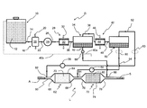
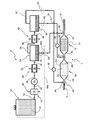
- This exhaust gas depollution treatment system comprises a device D for producing at least two reducing agents and an exhaust line L associated therewith.
- the device comprises a storage vessel 10 containing a basic compound 12 , preferably in aqueous solution, having the specific feature of decomposing into ammonia and a hydrocarbon substance, more particularly a hydrocarbon, either by hydrolysis or under the effect of heat.
- this basic compound can be an organonitrogen compound. Separation of the compounds (such as ammonia and hydrocarbon) obtained by hydrolysis or thermolysis can be achieved through a series of condensations.
- This compound can be hexamethylenetetramine (in short HMT, more commonly known as urotropine) or an ammonium salt such as ammonium acetate.
- HMT hexamethylenetetramine
- ammonium salt such as ammonium acetate
- This vessel is connected by a line 14 to means 16 for heating the basic compound coming from this vessel.
- these heating means consist of a heat exchanger 18 traversed, on the one hand, by this compound and, on the other hand, by a heat source 20 , here the exhaust gases 20 of the engine, which transmits the heat it contains to this compound.
- heat source or of heating means commonly known can be considered, such as the engine coolant of the vehicle, the lubricant of this engine, burners, electric resistance heaters, . . . .
- This exchanger is connected by another line 22 to a compressor 24 of the heated compound.
- This compressor is connected by a line 26 to one of the first means 28 for cooling the hot compressed compound.
- These first cooling means comprise, by way of example, a cooler 30 in form of an exchanger traversed by the hot compressed compound from line 26 and by a cooling fluid such as outdoor fresh air 32 .
- a closed tank 34 forming first storage and separation means for the cooled compound is connected to this cooler by a line 36 .
- This tank comprises two outlet lines 38 , 40 .
- Gas outlet line 38 leads to second cooling means 42 that are advantageously similar to the first means with another cooler 44 swept by a cooling fluid 46 , here also outdoor air.
- This cooler is in turn connected by a line 48 to a closed receptacle 50 forming second storage and separation means, which also comprises two outlet lines, a gaseous fluid outlet line 52 located in the upper part of the receptacle and a liquid fluid outlet line 54 located in the lower part of this receptacle.
- the two outlet lines 52 and 54 of this receptacle are each provided with fluid circulation control means, here a liquid metering pump 56 arranged on line 52 and a gas metering pump 58 arranged on line 54 .
- fluid circulation control means here a liquid metering pump 56 arranged on line 52 and a gas metering pump 58 arranged on line 54 .
- aqueous liquid outlet line 40 of tank 34 comprises a fluid circulation control means that can come in form of a cock, a valve, a metering pump, . . . .
- device D belongs to a system intended for depollution treatment of exhaust gases circulating in an exhaust line L, between an inlet for a gas (arrow A) resulting from the combustion of a fuel mixture of an internal-combustion engine and an outlet (arrow S) for discharge to the atmosphere.
- This exhaust line comprises an exhaust tube 60 housing an SCR catalyst 62 using ammonia as the reducing agent.
- This SCR catalyst comprises a tubular casing 64 with an inlet box 66 for the exhaust gases coming from the engine and a treated gas outlet box 68 connected to the exhaust tube for discharge of the depolluted exhaust gases to the atmosphere (arrow S).
- Casing 64 contains a filter support 70 arranged between the inlet and outlet boxes.
- This body preferably monolithic, comprises a support wherein one or more catalytic reactants are set so as to act upon the NOx of these exhaust gases.
- an additional SCR catalyst 72 is arranged on this tube 60 between SCR catalyst 62 and the exhaust gas outlet (arrow S).
- This additional catalyst preferably comprises a tubular casing 74 , an inlet box 76 connected by a portion of exhaust tube 60 to outlet box 68 of first SCR catalyst 62 and an outlet box 78 connected to this exhaust tube for discharge of the depolluted exhaust gases to the atmosphere (arrow S).
- Casing 74 also comprises a filter support 80 , preferably monolithic, which is chemically active so as to act upon the NOx of the exhaust gases coming from SCR catalyst 62 .
- this additional catalyst has the particular feature of acting upon the NOx by using a hydrocarbon substance as the reducing agent.
- this additional SCR catalyst can be replaced by a particulate filter or a catalyzed particulate filter comprising a filter support impregnated with one or more catalytic reactants so as to act upon the NOx and/or on the exotherm of this filter.
- the hydrocarbon substance is used to reduce the NOx stored in the catalyzed particulate filter and/or to generate the exotherm required for combustion of the particulate matter present in this filter.
- outlet line 52 carrying the gaseous fluid out of receptacle 50 ends at an injection point 82 for the ammonia-containing reducing agent in the portion of exhaust tube 60 located upstream from inlet box 66 of main catalyst 62 , thus forming injection means for the ammonia-containing reducing agent.
- liquid fluid outlet line 54 ends at a branch connection 84 of exhaust tube 60 . This branch connection is arranged between main catalyst outlet box 68 and additional catalyst inlet box 76 .
- Aqueous liquid outlet line 40 ends at a connection pipe 86 arranged downstream from the additional catalyst, between its outlet box 78 and the exhaust gas outlet (arrow S), so as to form intake means for this liquid in this line.
- liquid fluid outlet line 52 can end into inlet box 66 of main catalyst 62
- gaseous fluid outlet line 54 can end into inlet box 76 of additional catalyst 72
- aqueous liquid outlet line 40 can end into outlet box 78 of this additional catalyst.
- aqueous liquid outlet line 40 may also be free, as illustrated in dotted line ( 40 a ) in the FIGURE, so as to discharge the liquid concerned to the outside, or connected to vessel 10 ( 40 b ) so as to mix with the compound it contains.
- compound 12 contained in vessel 10 is an aqueous hexamethylenetetramine (HMT) solution (C 6 H 12 N 4 +H 2 O).
- HMT aqueous hexamethylenetetramine
- the HMT is initially in the solid phase, preferably in form of small pellets (approximately ten mm), so as to be easily stored. This HMT can thus be mixed with water in order to obtain the aqueous solution that is then fed into vessel 10 .
- An alternative consists in dissolving the pellets in water only as and when needed, which affords the advantage of decreasing the storage volumes.
- the water required for this dissolution can come from the device itself, as explained below.
- This solution is first heated to a minimum temperature close to 260° C., and preferably to a temperature below the cracking or reaction temperature of hydrocarbon substances by flowing through exchanger 18 while undergoing hydrolysis.
- the mixture obtained contains ammonia (NH 3 ) and formaldehyde (H 2 CO) gas phases associated with steam.
- the mixture obtained is then sent to compressor 24 through line 22 in order to be compressed.
- this compression ranges between 4 and 10 bars.
- the compressed mixture is then cooled by passing through cooler 30 at a temperature ranging from about 150° C. to about 180° C. depending on the pressure of the mixture. Cooling has the effect of condensing the steam and of feeding into tank 34 , through line 36 , a mixture of two phases with a gas phase comprising a mixture of ammonia and of formaldehyde (NH 3 +H 2 CO) and a liquid phase with water (H 2 O).
- a gas phase comprising a mixture of ammonia and of formaldehyde (NH 3 +H 2 CO) and a liquid phase with water (H 2 O).
- Fluid circulation control means 59 allows to stop the water circulation in the line when the level is insufficient in tank 34 and/or to control the amount of water sent to vessel 10 so as to obtain the desired amount of aqueous HMT solution.
- Fluid circulation control means 59 can also be designed in such a way that it allows to send the water to the exhaust tube through connection pipe 86 and/or to the outside through free liquid outlet line 40 a and/or to feed it into vessel 10 through line 40 b.
- the gaseous mixture contained in the top of this tank is discharged through gas outlet line 38 to second cooler 44 through which it flows so as to be cooled to around ambient temperature.
- Cooling allows to condense the hydrocarbon vapour phase to a liquid phase.
- line 48 carries towards receptacle 50 a mixture of two phases, a hydrocarbon liquid phase (formaldehyde H 2 CO) resulting from cooling in cooler 44 , and an ammonia gas phase (NH 3 ). These two phases are separated in this receptacle into a hydrocarbon liquid phase in the bottom and an ammonia gas phase in the upper part thereof.
- a hydrocarbon liquid phase formaldehyde H 2 CO
- NH 3 ammonia gas phase
- gaseous ammonia is injected through gaseous fluid outlet line 52 into the exhaust line at point 82 upstream from catalyst 62 when the liquid metering pump 58 is actuated, notably under the effect of control means such as the calculator of the vehicle.
- This ammonia thus mixes with the hot exhaust gases.
- the mixture thus formed reacts with the NOx of the exhaust gases when flowing through the main SCR catalyst, thus providing NOx depollution treatment.
- liquid hydrocarbon is sent through liquid fluid line 54 to the exhaust line upstream from additional catalyst 72 through branch connection 84 .
- the hydrocarbon injected into tube 60 vaporizes on contact with the exhaust gases coming from the main SCR catalyst. This vaporized hydrocarbon mixes with the exhaust gases by reacting with the NOx that have not been reduced when flowing through the additional SCR catalyst. This therefore allows to finalize the NOx depollution treatment.
- ammonia gas phase and/or the hydrocarbon liquid phase can optionally be stored in accumulators, respectively a gas accumulator 90 and a liquid accumulator 92 for subsequent use when one and/or the other of the metering pumps is not active in relation with the engine running conditions.
- the hydrocarbon is oxidized by the catalyst. This reaction generates an exotherm that is used to initiate the combustion of the particles trapped in the filter.
- the two catalysts can be used according to a strategy, generally for engine cold start, wherein only conventional SCR catalyst 72 is used with the hydrocarbon from outlet line 54 when the exhaust gas temperature is insufficient to make main SCR catalyst 62 operative. As soon as the temperature of these gases is sufficient (of the order of 200° C.), main SCR catalyst 62 is active by reacting with the ammonia delivered by outlet line 52 and additional SCR catalyst 72 can be made inoperative by deactivating gas metering pump 56 .
- compressor 24 metering pumps 56 , 58 and control means 59 are controlled by any means such as the engine calculator, so as to be actuated according to the various depollution strategies contained in the charts of this calculator.
- liquid outlet line 54 ends at injection point 82 and gas outlet line 52 ends at branch connection 84 .
Landscapes
- Chemical & Material Sciences (AREA)
- Engineering & Computer Science (AREA)
- Chemical Kinetics & Catalysis (AREA)
- Health & Medical Sciences (AREA)
- Toxicology (AREA)
- Combustion & Propulsion (AREA)
- Mechanical Engineering (AREA)
- General Engineering & Computer Science (AREA)
- Exhaust Gas After Treatment (AREA)
- Exhaust Gas Treatment By Means Of Catalyst (AREA)
Abstract
The present invention relates to a method of treating exhaust gas pollutants, notably of an internal-combustion engine, with a system comprising an exhaust line (L) with selective catalytic reduction catalysis means (62) and injection means (82) for injecting a reducing agent into the line so as to treat the pollutants, characterized in that it consists in:
-
- heating an organonitrogen compound so as to decompose it into a mixture of at least an ammonia-containing reducing agent in the gas phase, another reducing agent in the gas phase and steam,
- compressing, then cooling this mixture so as to condense the steam to a liquid water phase and to obtain a gas phase of one of the two reducing agents and a liquid phase of the other reducing agent,
- injecting one of the reducing agents into the exhaust line in combination with said catalysis means (62) in order to treat the pollutants of these gases.
Description
The present invention relates to a method intended for depollution treatment of exhaust gases, notably of an internal-combustion engine in a motor vehicle.
It more particularly concerns a method of treating pollutants contained in the exhaust gases of an auto-ignition internal-combustion engine, notably of Diesel type, but it excludes in no way such a method for spark-ignition engines, such as those running on a gaseous fuel or gasoline, and in particular with a lean mixture.
It also relates to an exhaust gas depollution treatment system using this method.
As it is well known, the exhaust gases of these engines contain many pollutants, such as unburnt hydrocarbons, carbon monoxide, nitrogen oxides (NO and NO2), more commonly referred to as NOx, for engines running on gasoline or gas, and additionally particles for Diesel type engines.
In order to comply with emission standards and to preserve the environment, these pollutants have to be treated prior to discharging the exhaust gases into the atmosphere.
As it is generally known, this is achieved by means of a system for treating the exhaust gas circulating in the exhaust line of the engine.
Thus, catalysis means, more commonly referred to as oxidation catalysts, allow to oxidize the unburnt hydrocarbons and the carbon monoxide for engines running with a lean mixture.
For a Diesel engine exhaust line, a particulate filter can be arranged on this line in order to retain the particulates present in the exhaust gas and thus to prevent them from being discharged into the atmosphere.
This filter, which can also be a catalyzed filter, has to be periodically regenerated in order to keep all its filtration capacities. The regeneration operations mainly consist in increasing the temperature of the filter, generally by increasing the richness of the exhaust gases flowing therethrough. The higher temperature that is obtained allows to carry out combustion of the particulate matter retained in this filter.
Furthermore, in order to allow NOx treatment, the exhaust gases also flow through other catalysis means, notably SCR (Selective Catalytic Reduction) catalyst type catalysts. This SCR catalyst allows to selectively reduce the NOx to nitrogen through the action of a reducing agent.
This agent, generally injected upstream from the SCR catalyst, can be ammonia or a compound generating ammonia through decomposition, such as urea, or a hydrocarbon from a hydrocarbon-containing substance.
This reducing agent mixes with the exhaust gases, then it reacts with the NOx of the exhaust gases on the SCR catalyst according to several possible chemical reactions such as, for example:
4NH3+2NO+2NO2→4N2+6H2O or 4NH3+4NO+O2→4N2+6H2O.
4NH3+2NO+2NO2→4N2+6H2O or 4NH3+4NO+O2→4N2+6H2O.
The precursor of the reducing agent conventionally used for this application has to be stored in a large volume, whereas the space available in the vehicle is limited. A large volume is necessary because this precursor is stored in liquid form and diluted in water.
Besides, SCR catalysts, which use ammonia as the NOx reducing agent, are generally active only above a light-off temperature ranging between 180° C. and 250° C. depending on the nature of the catalyst. Below this temperature, and in particular upon cold start of the vehicle, the NOx are not treated by ammonia-based SCR catalysts.
The present invention allows to overcome the aforementioned drawbacks by using a compound of high density or stored in solid form. This allows the compound to be arranged in the vehicle with a restricted volume.
The present invention thus relates to a method of treating pollutants contained in exhaust gases, notably of an internal-combustion engine, with a system comprising an exhaust line with selective catalytic reduction catalysis means traversed by said gases and injection means for injecting a reducing agent into said line so as to treat said pollutants as they flow through said catalysis means, characterized in that it consists in:
-
- heating an organonitrogen compound so as to decompose it into a mixture of at least an ammonia-containing reducing agent in the gas phase, another reducing agent in the gas phase and steam,
- compressing, then cooling this mixture so as to condense the steam to a liquid water phase and to obtain a gas phase of one of the two reducing agents and a liquid phase of the other reducing agent,
- injecting one of the reducing agents into the exhaust line in combination with at least said catalysis means in order to treat the pollutants of these gases.
The method can consist in placing additional catalysis means on the exhaust line and in injecting the other reducing agent in combination with said additional catalysis means so as to treat the pollutants of the exhaust gases.
The method can consist in injecting water in the liquid phase into the exhaust line.
The method can consist in using water in the liquid phase to prepare an aqueous compound solution.
The method can consist in discharging the water in the liquid phase to the outside.
The method can consist in cooling, by first cooling means, the mixture so as to obtain a gas phase of two reducing agents and a liquid water phase, then in cooling, by second cooling means, the gas phase of two reducing agents so as to obtain a reducing agent in the gas phase and another reducing agent in the liquid phase.
The method can consist in heating the organonitrogen compound so as to obtain its decomposition into a mixture of at least a reducing agent containing ammonia and another reducing agent containing a hydrocarbon substance.
The invention also relates to a system for treating pollutants contained in the exhaust gases of an internal-combustion engine, comprising an exhaust line with selective catalytic reduction catalysis means traversed by said gases and means for injecting a reducing agent into said line so as to treat said pollutants upon passage thereof through said catalysis means, characterized in that it comprises a reducing agent production device with means for heating an organonitrogen compound so as to obtain a mixture of at least two reducing agents in the gas phase, one containing ammonia and steam.
The system can comprise additional catalysis means associated with means for injecting one of the reducing agents.
The other reducing agent in the gas phase can comprise a hydrocarbon substance.
The system can comprise means for cooling the mixture of the two reducing agents in the gas phase and the steam, allowing to obtain a liquid water phase and a liquid phase of at least one of the reducing agents.
The organonitrogen compound can comprise a compound that can decompose into ammonia and at least a hydrocarbon substance.
The organonitrogen compound can advantageously comprise hexamethylene-tetramine.
The organonitrogen compound can comprise an ammonium salt with an ammonium acetate.
Other features and advantages of the invention will be clear from reading the description hereafter, given by way of non limitative example, with reference to the accompanying sole FIGURE that shows the system according to the invention.
This exhaust gas depollution treatment system comprises a device D for producing at least two reducing agents and an exhaust line L associated therewith.
The device comprises a storage vessel 10 containing a basic compound 12, preferably in aqueous solution, having the specific feature of decomposing into ammonia and a hydrocarbon substance, more particularly a hydrocarbon, either by hydrolysis or under the effect of heat.
By way of example, this basic compound can be an organonitrogen compound. Separation of the compounds (such as ammonia and hydrocarbon) obtained by hydrolysis or thermolysis can be achieved through a series of condensations.
This compound can be hexamethylenetetramine (in short HMT, more commonly known as urotropine) or an ammonium salt such as ammonium acetate. These compounds can be advantageously stored in solid form. This allows to significantly reduce the size of the vessel and/or to increase the amount of compound transported.
This vessel is connected by a line 14 to means 16 for heating the basic compound coming from this vessel.
Advantageously, these heating means consist of a heat exchanger 18 traversed, on the one hand, by this compound and, on the other hand, by a heat source 20, here the exhaust gases 20 of the engine, which transmits the heat it contains to this compound.
Other types of heat source or of heating means commonly known can be considered, such as the engine coolant of the vehicle, the lubricant of this engine, burners, electric resistance heaters, . . . .
This exchanger is connected by another line 22 to a compressor 24 of the heated compound. This compressor is connected by a line 26 to one of the first means 28 for cooling the hot compressed compound.
These first cooling means comprise, by way of example, a cooler 30 in form of an exchanger traversed by the hot compressed compound from line 26 and by a cooling fluid such as outdoor fresh air 32.
A closed tank 34 forming first storage and separation means for the cooled compound is connected to this cooler by a line 36. This tank comprises two outlet lines 38, 40. An outlet line 38 for a fluid in gas form, referred to as gas outlet line, starts in the upper part of this tank and another outlet line 40 for a fluid in the liquid state, referred to as aqueous liquid outlet line, starts in the bottom of this tank.
This cooler is in turn connected by a line 48 to a closed receptacle 50 forming second storage and separation means, which also comprises two outlet lines, a gaseous fluid outlet line 52 located in the upper part of the receptacle and a liquid fluid outlet line 54 located in the lower part of this receptacle.
Preferably, the two outlet lines 52 and 54 of this receptacle are each provided with fluid circulation control means, here a liquid metering pump 56 arranged on line 52 and a gas metering pump 58 arranged on line 54.
Similarly, aqueous liquid outlet line 40 of tank 34 comprises a fluid circulation control means that can come in form of a cock, a valve, a metering pump, . . . .
In the example illustrated in the FIGURE, device D belongs to a system intended for depollution treatment of exhaust gases circulating in an exhaust line L, between an inlet for a gas (arrow A) resulting from the combustion of a fuel mixture of an internal-combustion engine and an outlet (arrow S) for discharge to the atmosphere.
This exhaust line comprises an exhaust tube 60 housing an SCR catalyst 62 using ammonia as the reducing agent.
This SCR catalyst comprises a tubular casing 64 with an inlet box 66 for the exhaust gases coming from the engine and a treated gas outlet box 68 connected to the exhaust tube for discharge of the depolluted exhaust gases to the atmosphere (arrow S).
Preferably, an additional SCR catalyst 72 is arranged on this tube 60 between SCR catalyst 62 and the exhaust gas outlet (arrow S). This additional catalyst preferably comprises a tubular casing 74, an inlet box 76 connected by a portion of exhaust tube 60 to outlet box 68 of first SCR catalyst 62 and an outlet box 78 connected to this exhaust tube for discharge of the depolluted exhaust gases to the atmosphere (arrow S).
Advantageously, this additional catalyst has the particular feature of acting upon the NOx by using a hydrocarbon substance as the reducing agent.
Alternatively, this additional SCR catalyst can be replaced by a particulate filter or a catalyzed particulate filter comprising a filter support impregnated with one or more catalytic reactants so as to act upon the NOx and/or on the exotherm of this filter. In this case, the hydrocarbon substance is used to reduce the NOx stored in the catalyzed particulate filter and/or to generate the exotherm required for combustion of the particulate matter present in this filter.
In the rest of the description below, by way of example only, we consider an exhaust line L with, between the exhaust gas inlet (arrow A) and the exhaust gas outlet (arrow S), and in this order, an SCR catalyst 62, referred to as main catalyst, and an additional SCR catalyst 72.
As illustrated in the sole FIGURE, outlet line 52 carrying the gaseous fluid out of receptacle 50 ends at an injection point 82 for the ammonia-containing reducing agent in the portion of exhaust tube 60 located upstream from inlet box 66 of main catalyst 62, thus forming injection means for the ammonia-containing reducing agent. In order to form means for feeding the hydrocarbon-based reducing agent into the exhaust line, liquid fluid outlet line 54 ends at a branch connection 84 of exhaust tube 60. This branch connection is arranged between main catalyst outlet box 68 and additional catalyst inlet box 76. Aqueous liquid outlet line 40 ends at a connection pipe 86 arranged downstream from the additional catalyst, between its outlet box 78 and the exhaust gas outlet (arrow S), so as to form intake means for this liquid in this line.
Without departing from the scope of the invention, the aforementioned lines can end into the boxes corresponding thereto. Thus, liquid fluid outlet line 52 can end into inlet box 66 of main catalyst 62, gaseous fluid outlet line 54 can end into inlet box 76 of additional catalyst 72 and aqueous liquid outlet line 40 can end into outlet box 78 of this additional catalyst.
The outlet of aqueous liquid outlet line 40 may also be free, as illustrated in dotted line (40 a) in the FIGURE, so as to discharge the liquid concerned to the outside, or connected to vessel 10 (40 b) so as to mix with the compound it contains.
The description is now continued on the basis of an example wherein compound 12 contained in vessel 10 is an aqueous hexamethylenetetramine (HMT) solution (C6H12N4+H2O).
The HMT is initially in the solid phase, preferably in form of small pellets (approximately ten mm), so as to be easily stored. This HMT can thus be mixed with water in order to obtain the aqueous solution that is then fed into vessel 10.
An alternative consists in dissolving the pellets in water only as and when needed, which affords the advantage of decreasing the storage volumes.
The water required for this dissolution can come from the device itself, as explained below.
This solution is first heated to a minimum temperature close to 260° C., and preferably to a temperature below the cracking or reaction temperature of hydrocarbon substances by flowing through exchanger 18 while undergoing hydrolysis.
The mixture obtained contains ammonia (NH3) and formaldehyde (H2CO) gas phases associated with steam. The mixture obtained is then sent to compressor 24 through line 22 in order to be compressed. Preferably, this compression ranges between 4 and 10 bars.
The compressed mixture is then cooled by passing through cooler 30 at a temperature ranging from about 150° C. to about 180° C. depending on the pressure of the mixture. Cooling has the effect of condensing the steam and of feeding into tank 34, through line 36, a mixture of two phases with a gas phase comprising a mixture of ammonia and of formaldehyde (NH3+H2CO) and a liquid phase with water (H2O).
In tank 34, the two phases separate and the water contained in the bottom of this tank is discharged through aqueous liquid outlet line 40. This water is then sent to either the exhaust tube through connection pipe 86, or to the outside through free liquid outlet line 40 a, or fed through line 40 b into vessel 10 in order to dissolve at least part of the HMT pellets contained therein so as to obtain a desired aqueous solution. Fluid circulation control means 59 allows to stop the water circulation in the line when the level is insufficient in tank 34 and/or to control the amount of water sent to vessel 10 so as to obtain the desired amount of aqueous HMT solution.
Of course, in the latter case and even if the water from the decomposition is recovered, a sufficient volume of water is first provided in tank 34 to dissolve the HMT contained in the vessel.
Fluid circulation control means 59 can also be designed in such a way that it allows to send the water to the exhaust tube through connection pipe 86 and/or to the outside through free liquid outlet line 40 a and/or to feed it into vessel 10 through line 40 b.
The gaseous mixture contained in the top of this tank is discharged through gas outlet line 38 to second cooler 44 through which it flows so as to be cooled to around ambient temperature.
Cooling allows to condense the hydrocarbon vapour phase to a liquid phase.
At the outlet of this cooler, line 48 carries towards receptacle 50 a mixture of two phases, a hydrocarbon liquid phase (formaldehyde H2CO) resulting from cooling in cooler 44, and an ammonia gas phase (NH3). These two phases are separated in this receptacle into a hydrocarbon liquid phase in the bottom and an ammonia gas phase in the upper part thereof.
The gaseous ammonia is injected through gaseous fluid outlet line 52 into the exhaust line at point 82 upstream from catalyst 62 when the liquid metering pump 58 is actuated, notably under the effect of control means such as the calculator of the vehicle.
This ammonia thus mixes with the hot exhaust gases. The mixture thus formed reacts with the NOx of the exhaust gases when flowing through the main SCR catalyst, thus providing NOx depollution treatment.
Similarly, when gas metering pump 56 is in operation, the liquid hydrocarbon is sent through liquid fluid line 54 to the exhaust line upstream from additional catalyst 72 through branch connection 84.
The hydrocarbon injected into tube 60 vaporizes on contact with the exhaust gases coming from the main SCR catalyst. This vaporized hydrocarbon mixes with the exhaust gases by reacting with the NOx that have not been reduced when flowing through the additional SCR catalyst. This therefore allows to finalize the NOx depollution treatment.
The ammonia gas phase and/or the hydrocarbon liquid phase can optionally be stored in accumulators, respectively a gas accumulator 90 and a liquid accumulator 92 for subsequent use when one and/or the other of the metering pumps is not active in relation with the engine running conditions.
It is possible to substitute for additional SCR catalyst 72 an oxidizing catalyzed particulate filter that also reacts to the hydrocarbon reducing agent from liquid outlet line 54.
In this case, the hydrocarbon is oxidized by the catalyst. This reaction generates an exotherm that is used to initiate the combustion of the particles trapped in the filter.
It can be noted that the two catalysts can be used according to a strategy, generally for engine cold start, wherein only conventional SCR catalyst 72 is used with the hydrocarbon from outlet line 54 when the exhaust gas temperature is insufficient to make main SCR catalyst 62 operative. As soon as the temperature of these gases is sufficient (of the order of 200° C.), main SCR catalyst 62 is active by reacting with the ammonia delivered by outlet line 52 and additional SCR catalyst 72 can be made inoperative by deactivating gas metering pump 56.
Of course, compressor 24, metering pumps 56, 58 and control means 59 are controlled by any means such as the engine calculator, so as to be actuated according to the various depollution strategies contained in the charts of this calculator.
The present invention is not limited to the example described and it encompasses any variant or equivalent covered by the present invention.
Notably, one may consider using another type of compound in vessel 10, which results in obtaining in receptacle 50 the ammonia in liquid form and another reducing agent in gas form.
In this case, liquid outlet line 54 ends at injection point 82 and gas outlet line 52 ends at branch connection 84.
Claims (15)
1. A method of treating pollutants contained in exhaust gases, notably of an internal-combustion engine, with a system comprising an exhaust line with selective catalytic reduction catalysis means traversed by said gases and injection means for injecting a reducing agent into said line so as to treat said pollutants as they flow through said catalysis means, characterized in that it consists in:
heating an organonitrogen compound so as to decompose it into a mixture of at least an ammonia-containing reducing agent in the gas phase, another reducing agent in the gas phase and steam,
compressing, then cooling this mixture so as to condense the steam to a liquid water phase and to obtain a gas phase of one of the two reducing agents and a liquid phase of the other reducing agent,
injecting one of the reducing agents into the exhaust line in combination with at least said catalysis means in order to treat the pollutants of these gases.
2. A pollutant treatment method as claimed in claim 1 , characterized in that it consists in placing additional catalysis means on the exhaust line and in injecting the other reducing agent in combination with said additional catalysis means so as to treat the pollutants of the exhaust gases.
3. A pollutant treatment method as claimed in claim 1 , characterized in that it consists in injecting the water in the liquid phase into the exhaust line.
4. A pollutant treatment method as claimed in claim 1 , characterized in that it consists in using the water in the liquid phase to prepare an aqueous compound solution.
5. A pollutant treatment method as claimed in claim 1 , characterized in that it consists in discharging the water in the liquid phase to the outside.
6. A pollutant treatment method as claimed in claim 1 , characterized in that it consists in cooling, by first cooling means, the mixture so as to obtain a gas phase of two reducing agents and a liquid water phase, then in cooling, by second cooling means, the gas phase of two reducing agents so as to obtain a reducing agent in the gas phase and another reducing agent in the liquid phase.
7. A pollutant treatment method as claimed in claim 1 , characterized in that it consists in heating the organonitrogen compound so as to obtain its decomposition into a mixture of at least a reducing agent containing ammonia and another reducing agent containing a hydrocarbon substance.
8. A system for treating pollutants contained in the exhaust gases of an internal-combustion engine, comprising an exhaust line with selective catalytic reduction catalysis means traversed by said gases and injection means for injecting a reducing agent into said line so as to treat said pollutants upon passage thereof through said catalysis means, characterized in that it comprises a reducing agent production device with means for heating an organonitrogen compound so as to obtain a mixture of at least two reducing agents in the gas phase, one containing ammonia and steam.
9. A pollutant treatment system as claimed in claim 8 , characterized in that it also comprises additional catalysis means associated with injection means for injecting one of the reducing agents.
10. A pollutant treatment system as claimed in claim 8 , characterized in that the other one of the two reducing agents in the gas phase comprises a hydrocarbon substance.
11. A pollutant treatment system as claimed in claim 8 , characterized in that the device comprises means for cooling the mixture of the two reducing agents in the gas phase and the steam, allowing to obtain a liquid water phase and a liquid phase of at least one of the reducing agents.
12. A pollutant treatment system as claimed in claim 8 , characterized in that the organonitrogen compound comprises a compound that can decompose into ammonia and at least a hydrocarbon substance.
13. A pollutant treatment system as claimed in claim 8 , characterized in that the organonitrogen compound comprises hexamethylenetetramine (C6H12N4).
14. A pollutant treatment system as claimed in claim 8 , characterized in that the organonitrogen compound comprises an ammonium salt.
15. A pollutant treatment system as claimed in claim 14 , characterized in that the ammonium salt comprises an ammonium acetate.
Applications Claiming Priority (3)
| Application Number | Priority Date | Filing Date | Title |
|---|---|---|---|
| FR09/06.015 | 2009-11-12 | ||
| FR0906015A FR2953737B1 (en) | 2009-12-11 | 2009-12-11 | PROCESS FOR TREATING POLLUTANTS CONTAINED IN EXHAUST GASES, IN PARTICULAR AN INTERNAL COMBUSTION ENGINE, AND INSTALLATION USING SUCH A METHOD |
| FR0906015 | 2009-12-11 |
Publications (2)
| Publication Number | Publication Date |
|---|---|
| US20110138780A1 US20110138780A1 (en) | 2011-06-16 |
| US8418443B2 true US8418443B2 (en) | 2013-04-16 |
Family
ID=42324628
Family Applications (1)
| Application Number | Title | Priority Date | Filing Date |
|---|---|---|---|
| US12/965,084 Expired - Fee Related US8418443B2 (en) | 2009-11-12 | 2010-12-10 | Method of treating pollutants contained in exhaust gases, notably of an internal-combustion engine, and system using same |
Country Status (5)
| Country | Link |
|---|---|
| US (1) | US8418443B2 (en) |
| EP (1) | EP2333262B1 (en) |
| JP (1) | JP2011122593A (en) |
| KR (1) | KR20110066865A (en) |
| FR (1) | FR2953737B1 (en) |
Cited By (12)
| Publication number | Priority date | Publication date | Assignee | Title |
|---|---|---|---|---|
| US20130239549A1 (en) * | 2012-03-16 | 2013-09-19 | Cary Henry | Aftertreatment system and method for pre-decomposed reductant solution |
| US10683787B2 (en) * | 2018-11-08 | 2020-06-16 | Faurecia Emissions Control Technologies, Usa, Llc | Automotive exhaust aftertreatment system having onboard ammonia reactor with hybrid heating |
| US10954840B2 (en) | 2017-08-02 | 2021-03-23 | Robert Bosch Gmbh | Def injection strategy for multiple injection systems |
| US11022014B1 (en) | 2020-04-28 | 2021-06-01 | Faurecia Emissions Control Technologies, Usa, Llc | Exhaust aftertreatment system with heated flash-boiling doser |
| US11092054B1 (en) | 2020-04-29 | 2021-08-17 | Faurecia Emissions Control Technologies, Usa, Llc | Flash-boiling doser with thermal transfer helix |
| US11098625B2 (en) | 2017-08-02 | 2021-08-24 | Robert Bosch Gmbh | Multiple def injection concept for reducing risk of solid deposits formation in diesel aftertreatment systems |
| US11193413B2 (en) | 2019-12-12 | 2021-12-07 | Faurecia Emissions Control Technologies, Usa, Llc | Exhaust aftertreatment system with virtual temperature determination and control |
| US11225894B1 (en) | 2020-06-30 | 2022-01-18 | Faurecia Emissions Control Technologies, Usa, Llc | Exhaust aftertreatment system with thermally controlled reagent doser |
| US11319853B2 (en) | 2020-03-31 | 2022-05-03 | Faurecia Emissions Control Technologies, Usa, Llc | Automotive exhaust aftertreatment system with doser |
| US11384667B2 (en) | 2020-05-29 | 2022-07-12 | Faurecia Emissions Control Technologies, Usa, Llc | Exhaust aftertreatment system with heated dosing control |
| US11421574B2 (en) | 2019-02-04 | 2022-08-23 | Vitesco Technologies GmbH | Method for injecting gaseous ammonia into a combustion engine exhaust line |
| US11511239B2 (en) | 2020-04-29 | 2022-11-29 | Faurecia Emissions Control Technologies, Usa, Llc | Heated flash-boiling doser with integrated helix |
Families Citing this family (18)
| Publication number | Priority date | Publication date | Assignee | Title |
|---|---|---|---|---|
| EP2543837B1 (en) * | 2010-03-05 | 2016-11-23 | Toyota Jidosha Kabushiki Kaisha | Exhaust gas purification apparatus of an internal combustion engine |
| JP5581790B2 (en) * | 2010-04-22 | 2014-09-03 | いすゞ自動車株式会社 | Ammonia supply system to SCR equipment |
| FI124227B (en) * | 2011-08-17 | 2014-05-15 | Wärtsilä Finland Oy | The method of operating the internal combustion engine and the arrangement of the internal combustion engine |
| DE102011111590A1 (en) * | 2011-08-25 | 2013-02-28 | Volkswagen Aktiengesellschaft | Exhaust gas treatment device, process for the treatment of exhaust gas and motor vehicle |
| WO2013160712A1 (en) * | 2012-04-26 | 2013-10-31 | Renault Trucks | System and method for treating nitrogen oxides contained in exhaust gases |
| EP2662128A1 (en) | 2012-05-09 | 2013-11-13 | Inergy Automotive Systems Research (Société Anonyme) | Method and system for purifying the exhaust gases of a combustion engine |
| KR101436936B1 (en) | 2013-06-05 | 2014-09-03 | 한국기계연구원 | A reactor for solid ammonium salt and control methode thereof and NOx emission purification system which using solid ammonium salt and selective catalytic reduction catalyst |
| EP2846011A1 (en) * | 2013-09-04 | 2015-03-11 | Inergy Automotive Systems Research (Société Anonyme) | Method and system for purifying the exhaust gases of a combustion engine |
| FR3013381B1 (en) * | 2013-11-15 | 2016-01-01 | IFP Energies Nouvelles | METHOD OF DEPOLLUTING EXHAUST GAS, ESPECIALLY OF INTERNAL COMBUSTION ENGINE, IN PARTICULAR FOR MOTOR VEHICLE, AND INSTALLATION USING SUCH A METHOD |
| DE102014001879A1 (en) | 2014-02-14 | 2015-08-20 | Deutz Aktiengesellschaft | Internal combustion engine |
| EP2927451B1 (en) * | 2014-04-01 | 2017-06-14 | Inergy Automotive Systems Research (Société Anonyme) | Supply system for use in a vehicle |
| EP3194739A1 (en) * | 2014-07-18 | 2017-07-26 | Plastic Omnium Advanced Innovation and Research | Ammonia generating system for use in a vehicle |
| EP2975233B1 (en) * | 2014-07-18 | 2018-06-06 | Plastic Omnium Advanced Innovation and Research | Ammonia precursor generating system for use in a vehicle |
| FR3029966B1 (en) * | 2014-12-11 | 2018-01-26 | Psa Automobiles Sa. | NOX NITROGEN OXIDE REDUCTION DEVICE FOR A THERMAL ENGINE EXHAUST LINE |
| EP3088231A1 (en) * | 2015-04-28 | 2016-11-02 | Inergy Automotive Systems Research (Société Anonyme) | Ammonia precursor refill device |
| US10718245B2 (en) | 2018-06-13 | 2020-07-21 | Deere & Company | Exhaust gas treatment system and method having improved low temperature performance |
| US10767532B2 (en) * | 2018-06-13 | 2020-09-08 | Deere & Company | Exhaust gas treatment system and method having improved low temperature performance |
| CN114991945B (en) * | 2022-04-21 | 2024-02-27 | 同济大学 | Ammonia fuel engine system based on internal combustion Rankine cycle and application thereof |
Citations (9)
| Publication number | Priority date | Publication date | Assignee | Title |
|---|---|---|---|---|
| US4927612A (en) * | 1985-10-04 | 1990-05-22 | Fuel Tech, Inc. | Reduction of nitrogen- and carbon-based pollutants |
| US5286467A (en) * | 1989-09-12 | 1994-02-15 | Fuel Tech, Inc. | Highly efficient hybrid process for nitrogen oxides reduction |
| WO1998042623A1 (en) | 1997-03-21 | 1998-10-01 | Ec&C Technologies | Methods for the production of ammonia from urea and uses thereof |
| US6739125B1 (en) * | 2002-11-13 | 2004-05-25 | Collier Technologies, Inc. | Internal combustion engine with SCR and integrated ammonia production |
| EP1479652A1 (en) | 2003-05-12 | 2004-11-24 | Hochschule Rapperswil, Institut für angewandte Umwelttechnik | Process and apparatus for the preparation of a nitrogen oxide reducer for flue gases |
| US6837041B2 (en) * | 2001-01-13 | 2005-01-04 | Fev Motorentechnik Gmbh | Method of converting a solid nitrogen-containing reducing agent to the gas phase for use in the reduction of nitrogen oxides in exhaust gases |
| WO2007049042A1 (en) | 2005-10-26 | 2007-05-03 | Imi Vision Limited | Exhaust gas treatment |
| US7390471B2 (en) * | 2005-11-17 | 2008-06-24 | Siemens Power Generation, Inc. | Apparatus and method for catalytic treatment of exhaust gases |
| US20120117947A1 (en) * | 2010-11-15 | 2012-05-17 | Gm Global Technology Operations, Inc. | NOx ADSORBER REGENERATION SYSTEM AND METHOD |
-
2009
- 2009-12-11 FR FR0906015A patent/FR2953737B1/en not_active Expired - Fee Related
-
2010
- 2010-10-28 EP EP10290585.8A patent/EP2333262B1/en not_active Not-in-force
- 2010-12-09 JP JP2010274634A patent/JP2011122593A/en active Pending
- 2010-12-09 KR KR1020100125576A patent/KR20110066865A/en not_active Application Discontinuation
- 2010-12-10 US US12/965,084 patent/US8418443B2/en not_active Expired - Fee Related
Patent Citations (10)
| Publication number | Priority date | Publication date | Assignee | Title |
|---|---|---|---|---|
| US4927612A (en) * | 1985-10-04 | 1990-05-22 | Fuel Tech, Inc. | Reduction of nitrogen- and carbon-based pollutants |
| US5286467A (en) * | 1989-09-12 | 1994-02-15 | Fuel Tech, Inc. | Highly efficient hybrid process for nitrogen oxides reduction |
| WO1998042623A1 (en) | 1997-03-21 | 1998-10-01 | Ec&C Technologies | Methods for the production of ammonia from urea and uses thereof |
| US7220395B2 (en) * | 1997-03-21 | 2007-05-22 | Ec&C Technologies, Inc. | Methods for the production of ammonia from urea and/or biuret, and uses for NOx and/or particulate matter removal |
| US6837041B2 (en) * | 2001-01-13 | 2005-01-04 | Fev Motorentechnik Gmbh | Method of converting a solid nitrogen-containing reducing agent to the gas phase for use in the reduction of nitrogen oxides in exhaust gases |
| US6739125B1 (en) * | 2002-11-13 | 2004-05-25 | Collier Technologies, Inc. | Internal combustion engine with SCR and integrated ammonia production |
| EP1479652A1 (en) | 2003-05-12 | 2004-11-24 | Hochschule Rapperswil, Institut für angewandte Umwelttechnik | Process and apparatus for the preparation of a nitrogen oxide reducer for flue gases |
| WO2007049042A1 (en) | 2005-10-26 | 2007-05-03 | Imi Vision Limited | Exhaust gas treatment |
| US7390471B2 (en) * | 2005-11-17 | 2008-06-24 | Siemens Power Generation, Inc. | Apparatus and method for catalytic treatment of exhaust gases |
| US20120117947A1 (en) * | 2010-11-15 | 2012-05-17 | Gm Global Technology Operations, Inc. | NOx ADSORBER REGENERATION SYSTEM AND METHOD |
Cited By (13)
| Publication number | Priority date | Publication date | Assignee | Title |
|---|---|---|---|---|
| US20130239549A1 (en) * | 2012-03-16 | 2013-09-19 | Cary Henry | Aftertreatment system and method for pre-decomposed reductant solution |
| US8844269B2 (en) * | 2012-03-16 | 2014-09-30 | Cummins Inc. | Aftertreatment system and method for pre-decomposed reductant solution |
| US11098625B2 (en) | 2017-08-02 | 2021-08-24 | Robert Bosch Gmbh | Multiple def injection concept for reducing risk of solid deposits formation in diesel aftertreatment systems |
| US10954840B2 (en) | 2017-08-02 | 2021-03-23 | Robert Bosch Gmbh | Def injection strategy for multiple injection systems |
| US10683787B2 (en) * | 2018-11-08 | 2020-06-16 | Faurecia Emissions Control Technologies, Usa, Llc | Automotive exhaust aftertreatment system having onboard ammonia reactor with hybrid heating |
| US11421574B2 (en) | 2019-02-04 | 2022-08-23 | Vitesco Technologies GmbH | Method for injecting gaseous ammonia into a combustion engine exhaust line |
| US11193413B2 (en) | 2019-12-12 | 2021-12-07 | Faurecia Emissions Control Technologies, Usa, Llc | Exhaust aftertreatment system with virtual temperature determination and control |
| US11319853B2 (en) | 2020-03-31 | 2022-05-03 | Faurecia Emissions Control Technologies, Usa, Llc | Automotive exhaust aftertreatment system with doser |
| US11022014B1 (en) | 2020-04-28 | 2021-06-01 | Faurecia Emissions Control Technologies, Usa, Llc | Exhaust aftertreatment system with heated flash-boiling doser |
| US11092054B1 (en) | 2020-04-29 | 2021-08-17 | Faurecia Emissions Control Technologies, Usa, Llc | Flash-boiling doser with thermal transfer helix |
| US11511239B2 (en) | 2020-04-29 | 2022-11-29 | Faurecia Emissions Control Technologies, Usa, Llc | Heated flash-boiling doser with integrated helix |
| US11384667B2 (en) | 2020-05-29 | 2022-07-12 | Faurecia Emissions Control Technologies, Usa, Llc | Exhaust aftertreatment system with heated dosing control |
| US11225894B1 (en) | 2020-06-30 | 2022-01-18 | Faurecia Emissions Control Technologies, Usa, Llc | Exhaust aftertreatment system with thermally controlled reagent doser |
Also Published As
| Publication number | Publication date |
|---|---|
| EP2333262A1 (en) | 2011-06-15 |
| EP2333262B1 (en) | 2013-05-01 |
| FR2953737A1 (en) | 2011-06-17 |
| US20110138780A1 (en) | 2011-06-16 |
| KR20110066865A (en) | 2011-06-17 |
| JP2011122593A (en) | 2011-06-23 |
| FR2953737B1 (en) | 2013-03-15 |
Similar Documents
| Publication | Publication Date | Title |
|---|---|---|
| US8418443B2 (en) | Method of treating pollutants contained in exhaust gases, notably of an internal-combustion engine, and system using same | |
| US8122712B2 (en) | Exhaust system with improved NOX emission control | |
| EP3581773B1 (en) | Exhaust gas treatment system and method having improved low temperature performance | |
| JP6357234B2 (en) | In particular, an exhaust gas purification method for an internal combustion engine, especially an automobile, and an apparatus using the same | |
| CN104053871B (en) | Exhaust after treatment system and the method for running the system | |
| US8555617B2 (en) | Exhaust gas treatment system including a four-way catalyst and urea SCR catalyst and method of using the same | |
| US8505279B2 (en) | Exhaust gas treatment system including a four-way catalyst and urea SCR catalyst and method of using the same | |
| US20190321782A1 (en) | Method for the Cleaning of Exhaust Gas from a Compression Ignition Engine | |
| CN104847460A (en) | Method for the purification of diesel engine exhaust gases | |
| US9702286B2 (en) | Exhaust gas purification system and exhaust gas purification method | |
| EA027298B1 (en) | Method and system for the removal of noxious compounds from engine exhaust gas | |
| KR20180041195A (en) | Exhaust gas treatment system and exhaust gas stream treatment method | |
| US9945278B2 (en) | Exhaust gas mixer | |
| Braun et al. | Potential technical approaches for improving low‐temperature NOx conversion of exhaust aftertreatment systems | |
| US10167758B2 (en) | Product for the depollution of exhaust gases, especially from an internal combustion engine, and method for the depollution of exhaust gases using said product | |
| US20220136424A1 (en) | Internal Combustion Engine Exhaust Aftertreatment System | |
| CN111102041A (en) | Exhaust gas treatment system and method for diagnosing an exhaust gas treatment system | |
| KR102353657B1 (en) | In particular, an exhaust gas decontamination facility of an internal combustion engine and a method of using the facility | |
| KR101316272B1 (en) | Cartridge type selective catalytic reduction system | |
| CN104136099B (en) | For removing the method and system of hazardous compound from engine exhaust | |
| Ren et al. | Exhaust system with improved NO X emission control |
Legal Events
| Date | Code | Title | Description |
|---|---|---|---|
| AS | Assignment |
Owner name: IFP ENERGIES NOUVELLES, FRANCE Free format text: ASSIGNMENT OF ASSIGNORS INTEREST;ASSIGNORS:MILLET, MARIE-NOELLE;COLLIOU, THIERRY;MARTIN, BRIGITTE;SIGNING DATES FROM 20101028 TO 20101108;REEL/FRAME:025471/0269 |
|
| REMI | Maintenance fee reminder mailed | ||
| LAPS | Lapse for failure to pay maintenance fees | ||
| STCH | Information on status: patent discontinuation |
Free format text: PATENT EXPIRED DUE TO NONPAYMENT OF MAINTENANCE FEES UNDER 37 CFR 1.362 |
|
| FP | Lapsed due to failure to pay maintenance fee |
Effective date: 20170416 |