US10954840B2 - Def injection strategy for multiple injection systems - Google Patents
Def injection strategy for multiple injection systems Download PDFInfo
- Publication number
- US10954840B2 US10954840B2 US16/635,747 US201816635747A US10954840B2 US 10954840 B2 US10954840 B2 US 10954840B2 US 201816635747 A US201816635747 A US 201816635747A US 10954840 B2 US10954840 B2 US 10954840B2
- Authority
- US
- United States
- Prior art keywords
- injectors
- diesel exhaust
- def
- film mass
- injector
- Prior art date
- Legal status (The legal status is an assumption and is not a legal conclusion. Google has not performed a legal analysis and makes no representation as to the accuracy of the status listed.)
- Active
Links
- 239000007924 injection Substances 0.000 title claims abstract description 63
- 238000002347 injection Methods 0.000 title claims abstract description 63
- 239000007788 liquid Substances 0.000 claims abstract description 45
- 239000012530 fluid Substances 0.000 claims abstract description 30
- 230000008929 regeneration Effects 0.000 claims abstract description 17
- 238000011069 regeneration method Methods 0.000 claims abstract description 17
- 230000015572 biosynthetic process Effects 0.000 claims description 20
- 238000000034 method Methods 0.000 claims description 17
- 230000001419 dependent effect Effects 0.000 claims description 5
- 239000007787 solid Substances 0.000 description 16
- 230000003197 catalytic effect Effects 0.000 description 9
- 239000003054 catalyst Substances 0.000 description 8
- 238000002485 combustion reaction Methods 0.000 description 8
- 238000010586 diagram Methods 0.000 description 6
- 230000008020 evaporation Effects 0.000 description 6
- 238000001704 evaporation Methods 0.000 description 6
- 230000003647 oxidation Effects 0.000 description 6
- 238000007254 oxidation reaction Methods 0.000 description 6
- QGZKDVFQNNGYKY-UHFFFAOYSA-N Ammonia Chemical compound N QGZKDVFQNNGYKY-UHFFFAOYSA-N 0.000 description 4
- 238000004891 communication Methods 0.000 description 4
- 239000006227 byproduct Substances 0.000 description 3
- 230000009977 dual effect Effects 0.000 description 3
- 238000012360 testing method Methods 0.000 description 3
- 229910021529 ammonia Inorganic materials 0.000 description 2
- 238000010276 construction Methods 0.000 description 2
- 238000011161 development Methods 0.000 description 2
- 230000018109 developmental process Effects 0.000 description 2
- MWUXSHHQAYIFBG-UHFFFAOYSA-N nitrogen oxide Inorganic materials O=[N] MWUXSHHQAYIFBG-UHFFFAOYSA-N 0.000 description 2
- 101100406879 Neurospora crassa (strain ATCC 24698 / 74-OR23-1A / CBS 708.71 / DSM 1257 / FGSC 987) par-2 gene Proteins 0.000 description 1
- GQPLMRYTRLFLPF-UHFFFAOYSA-N Nitrous Oxide Chemical compound [O-][N+]#N GQPLMRYTRLFLPF-UHFFFAOYSA-N 0.000 description 1
- XSQUKJJJFZCRTK-UHFFFAOYSA-N Urea Chemical compound NC(N)=O XSQUKJJJFZCRTK-UHFFFAOYSA-N 0.000 description 1
- 230000002411 adverse Effects 0.000 description 1
- OHJMTUPIZMNBFR-UHFFFAOYSA-N biuret Chemical compound NC(=O)NC(N)=O OHJMTUPIZMNBFR-UHFFFAOYSA-N 0.000 description 1
- 238000004422 calculation algorithm Methods 0.000 description 1
- 238000004364 calculation method Methods 0.000 description 1
- 239000004202 carbamide Substances 0.000 description 1
- 238000006243 chemical reaction Methods 0.000 description 1
- 238000004590 computer program Methods 0.000 description 1
- 230000003247 decreasing effect Effects 0.000 description 1
- 239000007789 gas Substances 0.000 description 1
- 238000010438 heat treatment Methods 0.000 description 1
- 230000010354 integration Effects 0.000 description 1
- 230000003287 optical effect Effects 0.000 description 1
- 101150093826 par1 gene Proteins 0.000 description 1
- 238000012545 processing Methods 0.000 description 1
- 230000004044 response Effects 0.000 description 1
- 239000012899 standard injection Substances 0.000 description 1
- 230000001360 synchronised effect Effects 0.000 description 1
- 230000001052 transient effect Effects 0.000 description 1
- 230000007704 transition Effects 0.000 description 1
- 238000011144 upstream manufacturing Methods 0.000 description 1
Images


Classifications
-
- F—MECHANICAL ENGINEERING; LIGHTING; HEATING; WEAPONS; BLASTING
- F01—MACHINES OR ENGINES IN GENERAL; ENGINE PLANTS IN GENERAL; STEAM ENGINES
- F01N—GAS-FLOW SILENCERS OR EXHAUST APPARATUS FOR MACHINES OR ENGINES IN GENERAL; GAS-FLOW SILENCERS OR EXHAUST APPARATUS FOR INTERNAL COMBUSTION ENGINES
- F01N3/00—Exhaust or silencing apparatus having means for purifying, rendering innocuous, or otherwise treating exhaust
- F01N3/08—Exhaust or silencing apparatus having means for purifying, rendering innocuous, or otherwise treating exhaust for rendering innocuous
- F01N3/10—Exhaust or silencing apparatus having means for purifying, rendering innocuous, or otherwise treating exhaust for rendering innocuous by thermal or catalytic conversion of noxious components of exhaust
- F01N3/18—Exhaust or silencing apparatus having means for purifying, rendering innocuous, or otherwise treating exhaust for rendering innocuous by thermal or catalytic conversion of noxious components of exhaust characterised by methods of operation; Control
- F01N3/20—Exhaust or silencing apparatus having means for purifying, rendering innocuous, or otherwise treating exhaust for rendering innocuous by thermal or catalytic conversion of noxious components of exhaust characterised by methods of operation; Control specially adapted for catalytic conversion ; Methods of operation or control of catalytic converters
- F01N3/2066—Selective catalytic reduction [SCR]
- F01N3/208—Control of selective catalytic reduction [SCR], e.g. dosing of reducing agent
-
- B—PERFORMING OPERATIONS; TRANSPORTING
- B01—PHYSICAL OR CHEMICAL PROCESSES OR APPARATUS IN GENERAL
- B01D—SEPARATION
- B01D53/00—Separation of gases or vapours; Recovering vapours of volatile solvents from gases; Chemical or biological purification of waste gases, e.g. engine exhaust gases, smoke, fumes, flue gases, aerosols
- B01D53/34—Chemical or biological purification of waste gases
- B01D53/92—Chemical or biological purification of waste gases of engine exhaust gases
- B01D53/94—Chemical or biological purification of waste gases of engine exhaust gases by catalytic processes
- B01D53/9404—Removing only nitrogen compounds
- B01D53/9409—Nitrogen oxides
- B01D53/9431—Processes characterised by a specific device
-
- B—PERFORMING OPERATIONS; TRANSPORTING
- B01—PHYSICAL OR CHEMICAL PROCESSES OR APPARATUS IN GENERAL
- B01F—MIXING, e.g. DISSOLVING, EMULSIFYING OR DISPERSING
- B01F25/00—Flow mixers; Mixers for falling materials, e.g. solid particles
- B01F25/30—Injector mixers
-
- B01F5/04—
-
- F—MECHANICAL ENGINEERING; LIGHTING; HEATING; WEAPONS; BLASTING
- F01—MACHINES OR ENGINES IN GENERAL; ENGINE PLANTS IN GENERAL; STEAM ENGINES
- F01N—GAS-FLOW SILENCERS OR EXHAUST APPARATUS FOR MACHINES OR ENGINES IN GENERAL; GAS-FLOW SILENCERS OR EXHAUST APPARATUS FOR INTERNAL COMBUSTION ENGINES
- F01N13/00—Exhaust or silencing apparatus characterised by constructional features ; Exhaust or silencing apparatus, or parts thereof, having pertinent characteristics not provided for in, or of interest apart from, groups F01N1/00 - F01N5/00, F01N9/00, F01N11/00
- F01N13/009—Exhaust or silencing apparatus characterised by constructional features ; Exhaust or silencing apparatus, or parts thereof, having pertinent characteristics not provided for in, or of interest apart from, groups F01N1/00 - F01N5/00, F01N9/00, F01N11/00 having two or more separate purifying devices arranged in series
- F01N13/0093—Exhaust or silencing apparatus characterised by constructional features ; Exhaust or silencing apparatus, or parts thereof, having pertinent characteristics not provided for in, or of interest apart from, groups F01N1/00 - F01N5/00, F01N9/00, F01N11/00 having two or more separate purifying devices arranged in series the purifying devices are of the same type
-
- F—MECHANICAL ENGINEERING; LIGHTING; HEATING; WEAPONS; BLASTING
- F01—MACHINES OR ENGINES IN GENERAL; ENGINE PLANTS IN GENERAL; STEAM ENGINES
- F01N—GAS-FLOW SILENCERS OR EXHAUST APPARATUS FOR MACHINES OR ENGINES IN GENERAL; GAS-FLOW SILENCERS OR EXHAUST APPARATUS FOR INTERNAL COMBUSTION ENGINES
- F01N3/00—Exhaust or silencing apparatus having means for purifying, rendering innocuous, or otherwise treating exhaust
- F01N3/08—Exhaust or silencing apparatus having means for purifying, rendering innocuous, or otherwise treating exhaust for rendering innocuous
- F01N3/0807—Exhaust or silencing apparatus having means for purifying, rendering innocuous, or otherwise treating exhaust for rendering innocuous by using absorbents or adsorbents
- F01N3/0828—Exhaust or silencing apparatus having means for purifying, rendering innocuous, or otherwise treating exhaust for rendering innocuous by using absorbents or adsorbents characterised by the absorbed or adsorbed substances
- F01N3/0842—Nitrogen oxides
-
- F—MECHANICAL ENGINEERING; LIGHTING; HEATING; WEAPONS; BLASTING
- F01—MACHINES OR ENGINES IN GENERAL; ENGINE PLANTS IN GENERAL; STEAM ENGINES
- F01N—GAS-FLOW SILENCERS OR EXHAUST APPARATUS FOR MACHINES OR ENGINES IN GENERAL; GAS-FLOW SILENCERS OR EXHAUST APPARATUS FOR INTERNAL COMBUSTION ENGINES
- F01N3/00—Exhaust or silencing apparatus having means for purifying, rendering innocuous, or otherwise treating exhaust
- F01N3/08—Exhaust or silencing apparatus having means for purifying, rendering innocuous, or otherwise treating exhaust for rendering innocuous
- F01N3/10—Exhaust or silencing apparatus having means for purifying, rendering innocuous, or otherwise treating exhaust for rendering innocuous by thermal or catalytic conversion of noxious components of exhaust
- F01N3/24—Exhaust or silencing apparatus having means for purifying, rendering innocuous, or otherwise treating exhaust for rendering innocuous by thermal or catalytic conversion of noxious components of exhaust characterised by constructional aspects of converting apparatus
- F01N3/28—Construction of catalytic reactors
- F01N3/2892—Exhaust flow directors or the like, e.g. upstream of catalytic device
-
- F—MECHANICAL ENGINEERING; LIGHTING; HEATING; WEAPONS; BLASTING
- F01—MACHINES OR ENGINES IN GENERAL; ENGINE PLANTS IN GENERAL; STEAM ENGINES
- F01N—GAS-FLOW SILENCERS OR EXHAUST APPARATUS FOR MACHINES OR ENGINES IN GENERAL; GAS-FLOW SILENCERS OR EXHAUST APPARATUS FOR INTERNAL COMBUSTION ENGINES
- F01N9/00—Electrical control of exhaust gas treating apparatus
-
- F—MECHANICAL ENGINEERING; LIGHTING; HEATING; WEAPONS; BLASTING
- F01—MACHINES OR ENGINES IN GENERAL; ENGINE PLANTS IN GENERAL; STEAM ENGINES
- F01N—GAS-FLOW SILENCERS OR EXHAUST APPARATUS FOR MACHINES OR ENGINES IN GENERAL; GAS-FLOW SILENCERS OR EXHAUST APPARATUS FOR INTERNAL COMBUSTION ENGINES
- F01N2560/00—Exhaust systems with means for detecting or measuring exhaust gas components or characteristics
- F01N2560/02—Exhaust systems with means for detecting or measuring exhaust gas components or characteristics the means being an exhaust gas sensor
- F01N2560/026—Exhaust systems with means for detecting or measuring exhaust gas components or characteristics the means being an exhaust gas sensor for measuring or detecting NOx
-
- F—MECHANICAL ENGINEERING; LIGHTING; HEATING; WEAPONS; BLASTING
- F01—MACHINES OR ENGINES IN GENERAL; ENGINE PLANTS IN GENERAL; STEAM ENGINES
- F01N—GAS-FLOW SILENCERS OR EXHAUST APPARATUS FOR MACHINES OR ENGINES IN GENERAL; GAS-FLOW SILENCERS OR EXHAUST APPARATUS FOR INTERNAL COMBUSTION ENGINES
- F01N2610/00—Adding substances to exhaust gases
- F01N2610/02—Adding substances to exhaust gases the substance being ammonia or urea
-
- F—MECHANICAL ENGINEERING; LIGHTING; HEATING; WEAPONS; BLASTING
- F01—MACHINES OR ENGINES IN GENERAL; ENGINE PLANTS IN GENERAL; STEAM ENGINES
- F01N—GAS-FLOW SILENCERS OR EXHAUST APPARATUS FOR MACHINES OR ENGINES IN GENERAL; GAS-FLOW SILENCERS OR EXHAUST APPARATUS FOR INTERNAL COMBUSTION ENGINES
- F01N2610/00—Adding substances to exhaust gases
- F01N2610/14—Arrangements for the supply of substances, e.g. conduits
- F01N2610/1453—Sprayers or atomisers; Arrangement thereof in the exhaust apparatus
- F01N2610/146—Control thereof, e.g. control of injectors or injection valves
-
- F—MECHANICAL ENGINEERING; LIGHTING; HEATING; WEAPONS; BLASTING
- F01—MACHINES OR ENGINES IN GENERAL; ENGINE PLANTS IN GENERAL; STEAM ENGINES
- F01N—GAS-FLOW SILENCERS OR EXHAUST APPARATUS FOR MACHINES OR ENGINES IN GENERAL; GAS-FLOW SILENCERS OR EXHAUST APPARATUS FOR INTERNAL COMBUSTION ENGINES
- F01N2900/00—Details of electrical control or of the monitoring of the exhaust gas treating apparatus
- F01N2900/06—Parameters used for exhaust control or diagnosing
- F01N2900/08—Parameters used for exhaust control or diagnosing said parameters being related to the engine
-
- F—MECHANICAL ENGINEERING; LIGHTING; HEATING; WEAPONS; BLASTING
- F01—MACHINES OR ENGINES IN GENERAL; ENGINE PLANTS IN GENERAL; STEAM ENGINES
- F01N—GAS-FLOW SILENCERS OR EXHAUST APPARATUS FOR MACHINES OR ENGINES IN GENERAL; GAS-FLOW SILENCERS OR EXHAUST APPARATUS FOR INTERNAL COMBUSTION ENGINES
- F01N2900/00—Details of electrical control or of the monitoring of the exhaust gas treating apparatus
- F01N2900/06—Parameters used for exhaust control or diagnosing
- F01N2900/14—Parameters used for exhaust control or diagnosing said parameters being related to the exhaust gas
- F01N2900/1402—Exhaust gas composition
-
- F—MECHANICAL ENGINEERING; LIGHTING; HEATING; WEAPONS; BLASTING
- F01—MACHINES OR ENGINES IN GENERAL; ENGINE PLANTS IN GENERAL; STEAM ENGINES
- F01N—GAS-FLOW SILENCERS OR EXHAUST APPARATUS FOR MACHINES OR ENGINES IN GENERAL; GAS-FLOW SILENCERS OR EXHAUST APPARATUS FOR INTERNAL COMBUSTION ENGINES
- F01N2900/00—Details of electrical control or of the monitoring of the exhaust gas treating apparatus
- F01N2900/06—Parameters used for exhaust control or diagnosing
- F01N2900/18—Parameters used for exhaust control or diagnosing said parameters being related to the system for adding a substance into the exhaust
- F01N2900/1806—Properties of reducing agent or dosing system
- F01N2900/1812—Flow rate
-
- F—MECHANICAL ENGINEERING; LIGHTING; HEATING; WEAPONS; BLASTING
- F01—MACHINES OR ENGINES IN GENERAL; ENGINE PLANTS IN GENERAL; STEAM ENGINES
- F01N—GAS-FLOW SILENCERS OR EXHAUST APPARATUS FOR MACHINES OR ENGINES IN GENERAL; GAS-FLOW SILENCERS OR EXHAUST APPARATUS FOR INTERNAL COMBUSTION ENGINES
- F01N2900/00—Details of electrical control or of the monitoring of the exhaust gas treating apparatus
- F01N2900/06—Parameters used for exhaust control or diagnosing
- F01N2900/18—Parameters used for exhaust control or diagnosing said parameters being related to the system for adding a substance into the exhaust
- F01N2900/1806—Properties of reducing agent or dosing system
- F01N2900/1821—Injector parameters
-
- Y—GENERAL TAGGING OF NEW TECHNOLOGICAL DEVELOPMENTS; GENERAL TAGGING OF CROSS-SECTIONAL TECHNOLOGIES SPANNING OVER SEVERAL SECTIONS OF THE IPC; TECHNICAL SUBJECTS COVERED BY FORMER USPC CROSS-REFERENCE ART COLLECTIONS [XRACs] AND DIGESTS
- Y02—TECHNOLOGIES OR APPLICATIONS FOR MITIGATION OR ADAPTATION AGAINST CLIMATE CHANGE
- Y02T—CLIMATE CHANGE MITIGATION TECHNOLOGIES RELATED TO TRANSPORTATION
- Y02T10/00—Road transport of goods or passengers
- Y02T10/10—Internal combustion engine [ICE] based vehicles
- Y02T10/12—Improving ICE efficiencies
-
- Y—GENERAL TAGGING OF NEW TECHNOLOGICAL DEVELOPMENTS; GENERAL TAGGING OF CROSS-SECTIONAL TECHNOLOGIES SPANNING OVER SEVERAL SECTIONS OF THE IPC; TECHNICAL SUBJECTS COVERED BY FORMER USPC CROSS-REFERENCE ART COLLECTIONS [XRACs] AND DIGESTS
- Y02—TECHNOLOGIES OR APPLICATIONS FOR MITIGATION OR ADAPTATION AGAINST CLIMATE CHANGE
- Y02T—CLIMATE CHANGE MITIGATION TECHNOLOGIES RELATED TO TRANSPORTATION
- Y02T10/00—Road transport of goods or passengers
- Y02T10/10—Internal combustion engine [ICE] based vehicles
- Y02T10/40—Engine management systems
Definitions
- the present arrangement relates to a diesel exhaust fluid (DEF) injection strategy for multiple injections systems for a vehicle.
- DEF diesel exhaust fluid
- Selective catalytic converter is widely used as an effective method in reducing diesel NO x emissions.
- NO x nitrogen oxide(s)
- SULEV super ultra-low emissions vehicle
- High urea dosing rates will increase the level of DEF fluid liquid film wall thicknesses in SCR mixing sections, which in consequence might lead to increasing the risk of solid deposit byproduct formation.
- the risk of solid deposits formation is even higher during engine cold starts and/or low load operating conditions.
- Solid deposits in SCR systems significantly hamper the SCR mixer functionality. They may also increase the SCR exhaust back pressure, DEF fluid consumption and reduce the ammonia distribution at SCR inlet.
- the current arrangement considers the development of DEF fluid injection strategies for dual or multi DEF injection systems.
- the considered injection strategies are as follows:
- the standard mode which considers directly splitting the amount of DEF required for reducing NO x between two or more injectors.
- the injected DEF amount per injector is less than or equal to the dosing limit of the injection mixing section.
- High dosing rates in SCR system might be required to meet future low NO emission requirements such as low emission vehicle (LEV) III NO x emission requirements.
- Low temperature operating points i.e., exhaust temperatures between 180 ⁇ 250° C.
- biuret and other undesirable solid byproducts can be formed.
- These byproducts can be formed along the SCR mixer flaps, mixer walls and/or along the SCR catalyst upstream cone.
- the SCR solid deposit buildup can adversely increase exhaust back pressure, reduce the delivered ammonia amount or uniformity at SCR catalyst inlet, thus hampers the SCR system functionality.
- a method for controlling multiple injectors for injecting diesel exhaust fluid into a diesel exhaust system comprises: determining an amount of diesel exhaust fluid to reduce NOx emissions at an engine operating point and determining when there is a risk of deposit formation. When there is a risk of deposit formation, the method operates one of the injectors at a first injection rate and operates another one of the injectors at a second injection rate, each for a selected fraction of time.
- the method includes estimating a developed liquid film mass for each of the injectors, comparing the estimated developed liquid film mass for each of the injectors with a parameter limit film mass for each of the injectors, and when one of the estimated developed liquid film mass is not less than the corresponding parameter limit film mass, performing an ATS regeneration of the SCR to remove a deposit will take place.
- both of the estimated developed liquid film masses must be greater than the respective corresponding parameter limit film masses to perform an ATS regeneration of the SCR.
- the diesel exhaust system includes multiple injectors, a dosing controller for controlling the multiple injectors, and a processor.
- the processor is configured to: determine an amount of diesel exhaust fluid to reduce NOx emissions at an engine operating point and determine when there is a risk of deposit formation.
- the processor is configured to, with the dosing controller, operate one of the injectors at a first injection rate and operate another one of the injectors at a second injection rate, each for a selected fraction of time.
- the processor is configured to estimate a developed liquid film mass for each of the injectors, and compare the estimated developed liquid film mass with a parameter limit film mass for each of the injectors.
- FIG. 1 is a diagram of a diesel exhaust system with two DEF injection systems in conjunction with two impingement mixers.
- FIG. 2 is a diagram of a diesel exhaust system with two spaced compact DEF injection systems.
- FIG. 3 is a diagram of a diesel exhaust system with two DEF injectors in conjunction with two impingement mixers spaced from each other.
- FIG. 4 is a diagram of a diesel exhaust system with a compact DEF injection system spaced from a DEF injector in conjunction with an impingement mixer.
- FIG. 5 is a diagram of a diesel exhaust system with a compact DEF injection system having two injectors.
- FIG. 6 is a cross sectional view of the compact DEF injection system of FIG. 5 .
- FIG. 7 is a diagram of a diesel exhaust system with a compact DEF injection system having two injectors that is spaced from a compact DEF injection system having one injector.
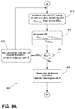
- FIG. 8A is a first portion of flowchart of one embodiment of a DEF dosing strategy for an injection system.
- FIG. 8B is a second portion of the flowchart of one embodiment of a DEF dosing strategy for an injection system.
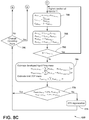
- FIG. 8C is a third portion of the flowchart of one embodiment of a DEF dosing strategy for a dual injection system.
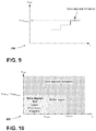
- FIG. 9 is a graph of a dosing limit per mixing section over time as related to solid deposits formation occurring when the limit is met.
- FIG. 10 is a graph showing when solid deposits being to form.
- the current arrangement considers the development of a dosing strategy for dual or multi DEF injection system installed in a serial fashion.
- the utilization of either two or multiple injectors for delivering the DEF fluid to the diesel exhaust flow will have a significant impact on reducing the risk of solid deposit formation.
- the alternating mode where one injector injects higher DEF dosing rates compared to others till reaching dosing limit threshold, then dosing rate increases at another DEF injector in an alternating fashion.
- the injected amount is greater than 100% of the rated or generally desired amount for constant injection by the DEF injector.
- a special case of this mode considers only injecting DEF via only one injector till reaching dosing limit threshold while others are idle. This injection mode is considered only when the DEF amount required for NO x conversion exceeds the dosing limit of the SCR mixing section. Thus, the injected amount is greater than 100% of the rated or generally desired amount for injection by the mixing section.
- FIG. 1 shows a diesel exhaust system 10 that includes a diesel oxidation catalyst (DOC) 14 in series with a diesel particulate filter (DPF) 16 and a SCR mixing section 20 that includes a dosing controller 24 , a first injector 26 and a first impingement plate 28 .
- the SCR mixing section 20 includes a second injector 36 , and a second impingement plate 38 .
- the diesel exhaust system 10 includes a selective catalytic converter (SCR) 40 .
- a NO x sensor is not provided and an NO x model determines and obtains NO x value for the exhaust stream.
- a NO x sensor 44 is provided to provide an output to an electronic control unit (ECU) 50 .
- ECU electronice control unit
- an exhaust temperature model determines exhaust temperature for the exhaust stream.
- an exhaust temperature sensor 49 provides an exhaust temperature output to the ECU 50 .
- the ECU 50 includes an electronic processor 54 having a memory 56 .
- the memory 56 may include non-transitory computer readable memory, such as volatile memory, non-volatile memory, or a combination thereof and, in various constructions, may also store operating system software, applications/instructions data, and combinations thereof.
- the memory 56 may be read-only memory (“ROM”), random access memory (“RAM”) (e.g., dynamic RAM (“DRAM”), synchronous DRAM (“SDRAM”), etc.), electrically erasable programmable read-only memory (“EEPROM”), flash memory, a hard disk, an SD card, or other suitable magnetic, optical, physical, or electronic memory devices.
- the electronic processor 54 e.g., a microprocessor, application specific integrated circuit, etc.
- the dosing controller 24 is incorporated into the ECU 50 .
- the ECU 50 is separate from and in communication over a communication bus 60 with the dosing controller 24 .
- the dosing controller 24 includes an electronic processor and memory in another embodiment.
- the dosing controller 24 controls valves of the injectors 26 , 36 to inject DEF provided by a DEF storage tank.
- the communication bus 60 is a CAN bus, a FLEX RAY bus, or other type of communication bus.
- FIG. 1 shows an internal combustion engine 64 that provides exhaust for the diesel exhaust system 10 .
- FIG. 2 shows an embodiment of a diesel exhaust system 100 that includes a diesel oxidation catalyst (DOC) 114 in series with a selective catalytic converter (SCR) 116 and a first compact mixing section 120 there between.
- the first compact mixing section 120 defines a compact SCR mixer that includes a first injector 126 and a first impingement plate 128 .
- the first impingement plate 128 shown in broken line is removed and a portion of the exhaust pipe acts as an evaporation section.
- the algorithm controlling the diesel exhaust system 100 is independent of the presence of the first impingement plate 128 .
- a second compact mixing section 130 defines a compact SCR mixer that includes a second injector 136 , and a second impingement plate 138 .
- the first injector 126 and the second injector 136 are controlled by a dosing controller 124 .
- the second compact mixing section 130 is disposed between the SCR 116 and a selective catalytic converter (SCR) 140 .
- the SCR 116 includes a DPF in addition to the SCR.
- the diesel exhaust system 100 is provided with an internal combustion engine having an electronic control unit.
- FIG. 3 shows an embodiment of a diesel exhaust system 200 that includes a diesel oxidation catalyst (DOC) 214 in series with a selective catalytic converter (SCR) 216 and a first mixing section 220 there between.
- the first mixing section 220 includes a first injector 226 and a first impingement plate 228 .
- a second mixing section 230 includes a second injector 236 , and a second impingement plate 238 shown in broken line.
- the second impingement plate 228 shown in broken line is removed, and a portion of the exhaust pipe acts as an evaporation source.
- the first injector 226 and the second injector 236 are controlled by a dosing controller 224 .
- the second mixing section 230 is disposed between the SCR 216 and a selective catalytic converter (SCR) 240 .
- the SCR 216 includes a DPF that receives the SCR.
- the diesel exhaust system 200 is provided with an internal combustion engine having an electronic control unit.
- FIG. 4 shows an embodiment of a diesel exhaust system 300 that includes a diesel oxidation catalyst (DOC) 314 in series with a selective catalytic converter (SCR) 316 and a first compact mixing section 320 therebetween.
- the first compact mixing section 320 includes a first injector 326 and a first impingement plate 328 .
- a second mixing section 330 includes a second injector 336 , and a second impingement plate 338 .
- the first injector 326 and the second injector 336 are controlled by a dosing controller 324 .
- the SCR 316 includes a DPF in addition to the SCR.
- the diesel exhaust system 300 is provided with an internal combustion engine having an electronic control unit.
- FIG. 5 shows an embodiment of a diesel exhaust system 400 that includes a diesel oxidation catalyst (DOC) 414 in series with a selective catalytic converter (SCR) 416 and a compact mixing section 420 there between.
- the compact mixing section 420 includes a first injector 426 and a first impingement plate 428 , along with a second injector 436 , and a second impingement plate 438 .
- FIG. 6 shows a cross sectional view of the compact mixing section 420 in FIG. 5 , including an exit aperture 439 for exhaust flow.
- the multiple injectors 426 , 436 are provided in the single compact mixing section 420 of a compact SCR mixer.
- the first injector 426 and the second injector 436 are controlled by a dosing controller 424 .
- the SCR 416 includes a DPF in addition to the SCR.
- the diesel exhaust system 400 is provided with an internal combustion engine having an electronic control unit.
- FIG. 7 shows an embodiment of a diesel exhaust system 500 that includes a diesel oxidation catalyst (DOC) 514 in series with a selective catalytic converter (SCR) 516 and a first compact mixing section 520 there between.
- the first compact mixing section 520 includes a first injector 526 and a first impingement plate 528 .
- a second mixing section 530 includes a second injector 536 , a third injector 537 and at least a second impingement plate 538 .
- the second impingement plate is not provided and an evaporation section is defined by the interior of the pipe near the injectors 536 , 537 .
- the injectors 526 , 536 , 537 are controlled by a dosing controller 524 .
- FIG. 7 shows an additional injector spaced from second mixing section 530 that defines a compact SCR mixer.
- the SCR 516 includes a DPF in addition to the SCR.
- the diesel exhaust system 500 is provided with an internal combustion engine having an electronic control unit.
- the dosing controller 524 controls the tri-injection system to provide DEF to the exhaust stream.
- FIGS. 8A-8C illustrate a flowchart 600 of a computer program or a set of execution steps for an embodiment of a dosing strategy directed to a method for controlling multiple injectors of an injection system of the embodiments of FIGS. 1-6 having two injectors 26 , 36 or for the injection system of FIG. 7 having three injectors 526 , 536 , 537 .
- FIGS. 8A-8C will be discussed with respect to the embodiment of FIG. 1 as follows.
- the processing discussed in the flowchart 600 of FIG. 8A is performed by a processor of the ECU 50 , a processor of the dosing controller 24 or another controller, not discussed herein that executes steps stored in a memory or other device.
- various processors perform different steps.
- the dosing controller 24 may control the injectors 26 , 36 in response to outputs from the ECU 50 .
- FIG. 8A determines a DEF dosing amount from an engine operating point by the ECU 50 (step 610 ).
- the ECU 50 controls the engine operating point, which corresponds to revolutions per minute (RPM) of the internal combustion engine 64 and load/torque of the engine.
- NO x sensor 44 is used to sense a NO x value to assist, in combination with the engine operating point, determining the amount of diesel exhaust fluid ( ⁇ dot over (m) ⁇ DEF NOx ) to be provided to the diesel exhaust system 10 by the injectors 26 , 36 shown in FIG. 1 .
- Reference Value R is determined by the equation:
- R m . DEF inj ⁇ ⁇ 1 limit + m . DEF inj ⁇ ⁇ 2 limit m . DEF NOx as shown in FIG. 8A (step 615 ).
- the processor determines if the Reference value R is greater than or equal to 1 (decision step 620 ). When the value R is greater than or equal to “1” the program advances to operate in a standard injection mode A (step 625 ). In the standard mode, the amount of DEF output is split between the injectors 26 , 36 . The injected DEF per injector is less than the dosing limit values of the injection section so that the DEF fluid evaporates and no deposits form.
- the processor returns (step 610 ) to estimate DEF dosing at the engine operating point.
- changes in the engine operating point and DEF dosing are accounted for in operation of the internal combustion engine 64 .
- injection mode B (step 630 ) shown in FIGS. 8B and 8C .
- the value R less than “1” indicates that additional DEF beyond the rated limits of the mixing sections must be applied to treat the exhaust in the diesel exhaust system 10 . As discussed above, such additional DEF can cause the forming of solid deposits.
- Injection mode B operates to minimize and control the formation of solids in the diesel exhaust system 10 as follows.
- an amount to be injected from a first injector is determined from the equation:
- frac inj 1 represents a preselected fraction that varies between 0 and 1.
- DEF inj limit 1 represents a dosing limit for the injection rate of the first injector provided in the mixing section.
- the dosing limit is obtained from experimental testing of the mixing section, or calculated through analytical, empirical, semi-empirical or computational fluid dynamic modeling (step 650 ).
- exhaust temperature is either measured by a temperature sensor or calculated by a temperature to assist in determining the dosing limit.
- Mass flow rate is calculated in some embodiments.
- ⁇ dot over (m) ⁇ DEF inj1 represents the rate of DEF to be injected by the first injector, which is less than the injection rate for a second injector.
- the program (step 650 ) also determines a coefficient for the first injector from the equation:
- C DEF inj1 is the coefficient for the first injector.
- a first coefficient for the first injector and a second coefficient for the second injector are determined (step 650 ).
- the program then operates to apply the DEF from the first injector and the second injector in dependence upon the two coefficients times the desired amount of DEF required (step 655 ).
- the DEF applied by the second injector is greater than the dosing limit thereof.
- the time limit t inj limit is a selected fraction time of t deposit (t inj limit ⁇ t deposit ). This arrangement is shown in FIG. 10 and discussed later herein.
- ⁇ ⁇ ⁇ t ⁇ t inj limit 1 is such that the change of time is less, the program returns and again executes step 650 .
- the program advances to estimate developed liquid film mass (step 665 ).
- the program shown in FIG. 8B estimates developed liquid film mass based on the following equations (step 665 ). For the second injector, estimated developed liquid film mass is determined from the equation:
- the liquid film mass is determined by the equation:
- DEF inj 2 evaporate ⁇ ⁇ and ⁇ ⁇ m .
- DEF inj 1 evaporate are evaporation rates for the DEF mass from the first and second injectors. Thus, the amount of liquid film mass for the injectors is decreased based on the evaporation rate for the DEF.
- DEF mass is determined (step 655 ) in FIG. 8B from the equation:
- m limit inj 2 ⁇ ⁇ m . DEF inj ⁇ ⁇ 2 limit ⁇ ⁇ ⁇ t , wherein ⁇ ⁇ m . DEF inj ⁇ ⁇ 2 limit is dosing limit for the second injector of a mixing section. Integration over ⁇ t, the injection time interval, provides a DEF mass limit.
- the dosing limit can be obtained from experimental testing of a mixing section and stored, or can be calculated through analytical, empirical or semi-empirical modeling or computational fluid dynamic modeling.
- the program shown in FIG. 8B advances to compare the estimated developed liquid film mass determined for each injector, with the parameter limit film mass for each injector (step 670 ).
- Each of the parameter limit film masses is dependent on the engine operating point. The equations are as follows:
- par 2 is a selected parameter limit value for a maximum parameter limit film mass for the second injector
- par 1 is a selected parameter limit value for a maximum parameter limit film mass for the first injector.
- the par values are selected values greater than 0.
- ATS regeneration includes rapidly heating the exhaust gas to evaporate or otherwise remove deposit formation in the diesel exhaust system 10 .
- ATS regeneration occurs if either of the estimated developed liquid film mass is greater than the corresponding parameter limit film mass.
- ATS regeneration occurs only when both of the estimated developed liquid film mass are greater than the corresponding parameter limit film mass.
- the values for each estimated developed liquid film mass are reset to zero before, during, or after operation of the deposit removal (step 675 ).
- an amount to be injected from a first injector is determined from the equation:
- frac inj 2 represents a preselected fraction that varies between 0 and 1.
- DEF inj limit 2 represents a dosing limit for the mixing section.
- the dosing limit is obtained from experimental testing of the mixing section, or calculated through analytical, empirical, semi-empirical or computational fluid dynamic modeling (step 750 ).
- ⁇ dot over (m) ⁇ DEF inj2 represents the amount of DEF to be injected, which is less than the amount for a second injector.
- the program (step 750 ) also determines a coefficient for the second injector from the equation:
- C DEF inj2 is the coefficient for the second injector.
- the program then operates to apply the DEF from the first injector and the second injector in dependence upon the two coefficients multiplied times the desired amount of DEF required (step 755 ).
- the DEF applied by the first injector is greater than the limit for the first injector. Further, the DEF applied by the first injector is greater than the DEF applied by the second injector.
- t inj limit 1 is a selected fraction time of t deposit (t inj limit ⁇ t deposit ).
- step 760 the program advances to estimate developed liquid films mass (step 765 ).
- the program operates for estimating developed liquid film mass (step 765 ) based on the same equations set forth above for step 665 .
- estimated developed liquid film mass is determined for the first and the second injectors.
- an estimate limit DEF mass is also calculated (step 765 ) based on the equation
- m limit inj 1 ⁇ ⁇ m . DEF inj ⁇ ⁇ 1 limit ⁇ ⁇ ⁇ ⁇ t .
- the program advances and operates for comparing whether either of the estimated developed liquid film mass is not less than the corresponding parameter limit film mass (step 770 ).
- the program advances to perform an after treatment system (ATS) regeneration (step 775 ).
- the ATS regeneration heats the exhaust to evaporate or otherwise remove deposit formation in the diesel exhaust system 10 .
- both of the estimated developed liquid film masses must be greater than the corresponding parameter limit film massesto perform ATS regeneration.
- the program continues by advancing to a change in operating point decision (step 780 ).
- the operating point of the engine is determined, which can be used for estimating a DEF dosing amount for each of the injectors at either steady or dynamic operation conditions of the engine. If the operating point changes during dynamic engine operating conditions (i.e., transient operating conditions), the program returns to “A” in FIG. 8A . Thereafter, injection mode A may or may not be selected. If the operating point does not change significantly, the program returns to “B” in FIG. 8B and executes the steps of recalculating an injection rate for the second injector and the first injector. The program continues operation of injection mode B, except the first injector is now outputting less DEF as compared to the second injector. The program may recalculate the injection rates for the first and second injectors repeatedly.
- FIGS. 8A-8C are one example of an arrangement for controlling two or more injectors, including operating the injectors at greater than the dosing limits thereof. The steps shown can be provided in a different order. FIGS. 8B and 8C can be reversed so that injector 1 operates at a first injection rate initially, before the second injector. The first injection rate is higher than the second injection rate of the second injector.
- the DEF flow rate is determined from the operating point. In other embodiments, sensing NO x with the NO x sensor assists to determine the desired DEF flow rate.
- FIG. 9 is a graph 900 showing a limit for the injectors whereat solid deposits form over time.
- FIG. 10 is a graph 950 showing a solid deposit free range over time, followed by a transition time between the downward arrows wherein solid deposits start to form (buffer region) and thereafter when significant solid deposit formation occurs from the DEF injected into the diesel exhaust system.
- the DEF amount for one injector is output at a higher rate than the other injector such that deposits may form.
- the other injector provides DEF fluid at the higher rate.
- only one injector operates until the dosing threshold is attained therefore.
- the arrangement is directed to operating both the first injector and the second injector alternatively at high dosing amounts, while operating the other injector at a lower dosing amount. Switching between the respective injectors occurs when the time threshold for the operating point of an engine is met. Further, besides switching between the injectors to provide a high DEF output when necessary, the system calculates an estimated developed liquid film mass for each injector. When the developed liquid film mass is exceeded, ATS regeneration occurs to remove solid deposits.
- FIG. 7 In the embodiment of FIG. 7 , three injectors are illustrated. Thus, the equations in FIGS. 8A-8C are modified for an arrangement having three injectors. Further, in other embodiments, four or more injectors are contemplated. The calculations for the three or more injectors provide each injector exceeding a high dosing amount sequentially in one embodiment.
- diesel exhaust system includes a processor that is configured to, when both of the estimated developed liquid film mass is not less than the corresponding parameter limit film mass, perform an ATS regeneration.
- ATS regeneration occurs when each estimated developed liquid film mass is greater than the corresponding parameter limit film mass for the respective injector.
- the arrangement provides, among other things, a system and method for reducing and removing solid deposits formed by DEF fluid injected into a diesel exhaust system.
Landscapes
- Engineering & Computer Science (AREA)
- Chemical & Material Sciences (AREA)
- Chemical Kinetics & Catalysis (AREA)
- Combustion & Propulsion (AREA)
- General Engineering & Computer Science (AREA)
- Mechanical Engineering (AREA)
- Health & Medical Sciences (AREA)
- Toxicology (AREA)
- Biomedical Technology (AREA)
- Environmental & Geological Engineering (AREA)
- Analytical Chemistry (AREA)
- General Chemical & Material Sciences (AREA)
- Oil, Petroleum & Natural Gas (AREA)
- Exhaust Gas After Treatment (AREA)
Abstract
Description
as shown in
represents the injection rate limit for the first mixing section at the engine operating point. Finally,
represents the injection rate limit for the second mixing section at the engine operating point.
represents a dosing limit for the injection rate of the first injector provided in the mixing section. The dosing limit is obtained from experimental testing of the mixing section, or calculated through analytical, empirical, semi-empirical or computational fluid dynamic modeling (step 650). In some embodiments, exhaust temperature is either measured by a temperature sensor or calculated by a temperature to assist in determining the dosing limit. Mass flow rate is calculated in some embodiments. In the equation, {dot over (m)}DEF
C DEF
for the second injector (decision step 660). The time limit tinj
is such that the change of time is less, the program returns and again executes
are evaporation rates for the DEF mass from the first and second injectors. Thus, the amount of liquid film mass for the injectors is decreased based on the evaporation rate for the DEF.
is dosing limit for the second injector of a mixing section. Integration over Δt, the injection time interval, provides a DEF mass limit.
and wherein par2 is a selected parameter limit value for a maximum parameter limit film mass for the second injector, and
wherein par1 is a selected parameter limit value for a maximum parameter limit film mass for the first injector. The par values are selected values greater than 0.
represents a dosing limit for the mixing section. The dosing limit is obtained from experimental testing of the mixing section, or calculated through analytical, empirical, semi-empirical or computational fluid dynamic modeling (step 750). In the equation, {dot over (m)}DEF
for the first injector (decision step 760). The time limit
is a selected fraction time of tdeposit (tinj
is met, the program returns and again executes
Claims (20)
Priority Applications (1)
| Application Number | Priority Date | Filing Date | Title |
|---|---|---|---|
| US16/635,747 US10954840B2 (en) | 2017-08-02 | 2018-08-01 | Def injection strategy for multiple injection systems |
Applications Claiming Priority (3)
| Application Number | Priority Date | Filing Date | Title |
|---|---|---|---|
| US201762540212P | 2017-08-02 | 2017-08-02 | |
| PCT/IB2018/001035 WO2019025870A1 (en) | 2017-08-02 | 2018-08-01 | Def injection strategy for multiple injection systems |
| US16/635,747 US10954840B2 (en) | 2017-08-02 | 2018-08-01 | Def injection strategy for multiple injection systems |
Publications (2)
| Publication Number | Publication Date |
|---|---|
| US20200347764A1 US20200347764A1 (en) | 2020-11-05 |
| US10954840B2 true US10954840B2 (en) | 2021-03-23 |
Family
ID=63862182
Family Applications (1)
| Application Number | Title | Priority Date | Filing Date |
|---|---|---|---|
| US16/635,747 Active US10954840B2 (en) | 2017-08-02 | 2018-08-01 | Def injection strategy for multiple injection systems |
Country Status (4)
| Country | Link |
|---|---|
| US (1) | US10954840B2 (en) |
| CN (1) | CN111133178A (en) |
| DE (1) | DE112018003424T5 (en) |
| WO (1) | WO2019025870A1 (en) |
Families Citing this family (3)
| Publication number | Priority date | Publication date | Assignee | Title |
|---|---|---|---|---|
| CN112539099A (en) * | 2020-11-27 | 2021-03-23 | 潍柴动力股份有限公司 | SCR system, urea injection method thereof and tail gas aftertreatment system |
| EP4083397B1 (en) * | 2021-04-30 | 2024-04-03 | Volvo Truck Corporation | A method for reducing deposits related to a reduction agent in a portion of an exhaust aftertreatment system |
| CN114483267B (en) * | 2022-02-23 | 2023-03-10 | 一汽解放汽车有限公司 | Supply device and control method for SCR (selective catalytic reduction) dual-injection urea for vehicle |
Citations (38)
| Publication number | Priority date | Publication date | Assignee | Title |
|---|---|---|---|---|
| US5976475A (en) | 1997-04-02 | 1999-11-02 | Clean Diesel Technologies, Inc. | Reducing NOx emissions from an engine by temperature-controlled urea injection for selective catalytic reduction |
| US7028680B2 (en) | 2004-09-21 | 2006-04-18 | International Engine Intellectual Property Company, Llc | Two stage mixing system for exhaust gas recirculation (EGR) |
| US7032578B2 (en) | 2004-09-21 | 2006-04-25 | International Engine Intellectual Property Company, Llc | Venturi mixing system for exhaust gas recirculation (EGR) |
| US7140357B2 (en) | 2004-09-21 | 2006-11-28 | International Engine Intellectual Property Company, Llc | Vortex mixing system for exhaust gas recirculation (EGR) |
| US7552722B1 (en) | 2007-12-26 | 2009-06-30 | Toyota Motor Engineering & Manufacturing North America, Inc. | Exhaust gas recirculator devices |
| US20090173063A1 (en) | 2008-01-07 | 2009-07-09 | Boorse R Samuel | Mitigation of Particulates and NOx in Engine Exhaust |
| US7814745B2 (en) | 2007-07-17 | 2010-10-19 | Ford Global Technologies, Llc | Approach for delivering a liquid reductant into an exhaust flow of a fuel burning engine |
| US8006480B2 (en) | 2007-07-25 | 2011-08-30 | Eaton Corporation | Physical based LNT regeneration strategy |
| US8109077B2 (en) | 2006-10-11 | 2012-02-07 | Tenneco Automotive Operating Company Inc. | Dual injector system for diesel emissions control |
| US20130031891A1 (en) | 2011-08-05 | 2013-02-07 | Ponnathpur Chetan | Nh3 emissions management in a nox reduction system |
| US8418443B2 (en) | 2009-11-12 | 2013-04-16 | IFP Energies Nouvelles | Method of treating pollutants contained in exhaust gases, notably of an internal-combustion engine, and system using same |
| US20130115150A1 (en) * | 2011-11-08 | 2013-05-09 | Robert Bosch Gmbh | Scr catalyst system and method for the operation thereof |
| US8491842B2 (en) | 2008-10-06 | 2013-07-23 | Amminex Emissions Technology A/S | Release of stored ammonia at start-up |
| WO2014051617A1 (en) | 2012-09-28 | 2014-04-03 | Faurecia Emissions Control Technologies | Doser and mixer for a vehicle exhaust system |
| WO2014051605A1 (en) | 2012-09-28 | 2014-04-03 | Faurecia Emissions Control Technologies | Exhaust system mixer with impactor |
| US20140166141A1 (en) | 2012-12-13 | 2014-06-19 | Tenneco Automotive Operating Company Inc. | Reductant Injection System with Control Valve |
| US20140318112A1 (en) | 2013-04-29 | 2014-10-30 | GM Global Technology Operations LLC | Internal combustion engine and exhaust aftertreatment system |
| US8881712B2 (en) | 2008-06-12 | 2014-11-11 | Perkins Engines Company Limited | Exhaust gas mixing system |
| US20140360168A1 (en) | 2013-06-07 | 2014-12-11 | Jeffrey Michael Broderick | System and Method for Sequential Injection of Reagent to Reduce NOx from Combustion Sources |
| US20150013309A1 (en) | 2013-07-11 | 2015-01-15 | Ford Global Technologies, Llc | Ammonia storage management for scr catalyst |
| US8935918B2 (en) | 2010-04-23 | 2015-01-20 | GM Global Technology Operations LLC | Reconfigurable mixer for an exhaust aftertreatment system and method of using the same |
| US20150059317A1 (en) | 2013-08-27 | 2015-03-05 | GM Global Technology Operations LLC | System and method for enhancing the performance of a selective catalytic reduction device |
| WO2015071233A1 (en) | 2013-11-15 | 2015-05-21 | Robert Bosch Gmbh | Exhaust gas post treatment system |
| JP2015110929A (en) | 2013-12-06 | 2015-06-18 | 株式会社日本自動車部品総合研究所 | Exhaust emission control system |
| US20150285192A1 (en) | 2013-11-11 | 2015-10-08 | Borgwarner Inc. | Turbocharger with integrated venturi mixer and egr valve system |
| US9192892B2 (en) | 2014-01-16 | 2015-11-24 | Cummins Emission Solutions, Inc. | Selective dosing module control system |
| US20150345356A1 (en) | 2014-06-02 | 2015-12-03 | Caterpillar Inc. | Reductant dosing system having staggered injectors |
| EP2955351A1 (en) | 2014-06-12 | 2015-12-16 | Toyota Jidosha Kabushiki Kaisha | Filling of an urea water supply system |
| DE102011077156B4 (en) | 2011-06-07 | 2015-12-17 | Robert Bosch Gmbh | Exhaust system and injection module |
| US20160090887A1 (en) | 2014-09-26 | 2016-03-31 | Cummins Emission Solutions, Inc. | Integrative reductant system and method using constant volume injection |
| US9334778B2 (en) | 2013-03-07 | 2016-05-10 | Cummins Ip, Inc. | Solid ammonia delivery system |
| US20160160725A1 (en) | 2014-12-05 | 2016-06-09 | Caterpillar Inc. | Diesel Exhaust Fluid Dosing System for Diesel Engine Aftertreatment Module |
| US20160158714A1 (en) | 2014-12-04 | 2016-06-09 | GM Global Technology Operations LLC | Diesel exhaust fluid mixing system for a linear arrangement of diesel oxidation catalyst and selective catalytic reduction filter |
| US9375682B2 (en) | 2009-03-27 | 2016-06-28 | Emitec Gesellschaft Fuer Emissionstechnologie Mbh | Exhaust gas system with a reducing agent supply |
| US20170051654A1 (en) | 2015-08-19 | 2017-02-23 | Cummins, Inc. | Diagnostic methods for a high efficiency exhaust aftertreatment system |
| US20170130628A1 (en) * | 2015-11-09 | 2017-05-11 | Robert Bosch Gmbh | Method for operating an scr catalytic converter system of an internal combustion engine |
| US20170218828A1 (en) * | 2016-02-03 | 2017-08-03 | Robert Bosch Gmbh | Method for determining an ammonia mass flow |
| WO2018001789A1 (en) | 2016-06-29 | 2018-01-04 | Robert Bosch Gmbh | Mixer device for an exhaust-gas aftertreatment system of a motor vehicle, exhaust-gas aftertreatment system, and motor vehicle |
Family Cites Families (4)
| Publication number | Priority date | Publication date | Assignee | Title |
|---|---|---|---|---|
| DE102015221945A1 (en) * | 2015-11-09 | 2017-05-11 | Robert Bosch Gmbh | Method for diagnosing an SCR catalytic converter system of an internal combustion engine |
| CN106382145B (en) * | 2016-11-04 | 2019-04-02 | 江苏大学 | A kind of exhaust treatment system and control method based on NTP technology |
| US11098625B2 (en) * | 2017-08-02 | 2021-08-24 | Robert Bosch Gmbh | Multiple def injection concept for reducing risk of solid deposits formation in diesel aftertreatment systems |
| CN108595802B (en) * | 2018-04-13 | 2022-02-22 | 无锡威孚力达催化净化器有限责任公司 | Simulation-based urea crystallization risk evaluation method for SCR system |
-
2018
- 2018-08-01 US US16/635,747 patent/US10954840B2/en active Active
- 2018-08-01 DE DE112018003424.0T patent/DE112018003424T5/en not_active Withdrawn
- 2018-08-01 CN CN201880064235.3A patent/CN111133178A/en active Pending
- 2018-08-01 WO PCT/IB2018/001035 patent/WO2019025870A1/en active Application Filing
Patent Citations (42)
| Publication number | Priority date | Publication date | Assignee | Title |
|---|---|---|---|---|
| US5976475A (en) | 1997-04-02 | 1999-11-02 | Clean Diesel Technologies, Inc. | Reducing NOx emissions from an engine by temperature-controlled urea injection for selective catalytic reduction |
| US7028680B2 (en) | 2004-09-21 | 2006-04-18 | International Engine Intellectual Property Company, Llc | Two stage mixing system for exhaust gas recirculation (EGR) |
| US7032578B2 (en) | 2004-09-21 | 2006-04-25 | International Engine Intellectual Property Company, Llc | Venturi mixing system for exhaust gas recirculation (EGR) |
| US7140357B2 (en) | 2004-09-21 | 2006-11-28 | International Engine Intellectual Property Company, Llc | Vortex mixing system for exhaust gas recirculation (EGR) |
| US8109077B2 (en) | 2006-10-11 | 2012-02-07 | Tenneco Automotive Operating Company Inc. | Dual injector system for diesel emissions control |
| US7814745B2 (en) | 2007-07-17 | 2010-10-19 | Ford Global Technologies, Llc | Approach for delivering a liquid reductant into an exhaust flow of a fuel burning engine |
| US8006480B2 (en) | 2007-07-25 | 2011-08-30 | Eaton Corporation | Physical based LNT regeneration strategy |
| US7552722B1 (en) | 2007-12-26 | 2009-06-30 | Toyota Motor Engineering & Manufacturing North America, Inc. | Exhaust gas recirculator devices |
| US20090173063A1 (en) | 2008-01-07 | 2009-07-09 | Boorse R Samuel | Mitigation of Particulates and NOx in Engine Exhaust |
| US8881712B2 (en) | 2008-06-12 | 2014-11-11 | Perkins Engines Company Limited | Exhaust gas mixing system |
| US8491842B2 (en) | 2008-10-06 | 2013-07-23 | Amminex Emissions Technology A/S | Release of stored ammonia at start-up |
| US9375682B2 (en) | 2009-03-27 | 2016-06-28 | Emitec Gesellschaft Fuer Emissionstechnologie Mbh | Exhaust gas system with a reducing agent supply |
| US8418443B2 (en) | 2009-11-12 | 2013-04-16 | IFP Energies Nouvelles | Method of treating pollutants contained in exhaust gases, notably of an internal-combustion engine, and system using same |
| US8935918B2 (en) | 2010-04-23 | 2015-01-20 | GM Global Technology Operations LLC | Reconfigurable mixer for an exhaust aftertreatment system and method of using the same |
| DE102011077156B4 (en) | 2011-06-07 | 2015-12-17 | Robert Bosch Gmbh | Exhaust system and injection module |
| US20130031891A1 (en) | 2011-08-05 | 2013-02-07 | Ponnathpur Chetan | Nh3 emissions management in a nox reduction system |
| US20130115150A1 (en) * | 2011-11-08 | 2013-05-09 | Robert Bosch Gmbh | Scr catalyst system and method for the operation thereof |
| US20150240689A1 (en) | 2012-09-28 | 2015-08-27 | Faurecia Emissions Control Technologies, Usa, Llc | Exhaust system mixer with impactor |
| WO2014051617A1 (en) | 2012-09-28 | 2014-04-03 | Faurecia Emissions Control Technologies | Doser and mixer for a vehicle exhaust system |
| WO2014051605A1 (en) | 2012-09-28 | 2014-04-03 | Faurecia Emissions Control Technologies | Exhaust system mixer with impactor |
| US20140166141A1 (en) | 2012-12-13 | 2014-06-19 | Tenneco Automotive Operating Company Inc. | Reductant Injection System with Control Valve |
| US9334778B2 (en) | 2013-03-07 | 2016-05-10 | Cummins Ip, Inc. | Solid ammonia delivery system |
| US20140318112A1 (en) | 2013-04-29 | 2014-10-30 | GM Global Technology Operations LLC | Internal combustion engine and exhaust aftertreatment system |
| US20140360168A1 (en) | 2013-06-07 | 2014-12-11 | Jeffrey Michael Broderick | System and Method for Sequential Injection of Reagent to Reduce NOx from Combustion Sources |
| US20150013309A1 (en) | 2013-07-11 | 2015-01-15 | Ford Global Technologies, Llc | Ammonia storage management for scr catalyst |
| US20150059317A1 (en) | 2013-08-27 | 2015-03-05 | GM Global Technology Operations LLC | System and method for enhancing the performance of a selective catalytic reduction device |
| US20150285192A1 (en) | 2013-11-11 | 2015-10-08 | Borgwarner Inc. | Turbocharger with integrated venturi mixer and egr valve system |
| CN106030063A (en) | 2013-11-15 | 2016-10-12 | 罗伯特·博世有限公司 | Exhaust gas post treatment system |
| DE102013223313A1 (en) | 2013-11-15 | 2015-05-21 | Robert Bosch Gmbh | aftertreatment system |
| US20160356200A1 (en) | 2013-11-15 | 2016-12-08 | Robert Bosch Gmbh | Exhaust gas post treatment device |
| WO2015071233A1 (en) | 2013-11-15 | 2015-05-21 | Robert Bosch Gmbh | Exhaust gas post treatment system |
| JP2015110929A (en) | 2013-12-06 | 2015-06-18 | 株式会社日本自動車部品総合研究所 | Exhaust emission control system |
| US9192892B2 (en) | 2014-01-16 | 2015-11-24 | Cummins Emission Solutions, Inc. | Selective dosing module control system |
| US20150345356A1 (en) | 2014-06-02 | 2015-12-03 | Caterpillar Inc. | Reductant dosing system having staggered injectors |
| EP2955351A1 (en) | 2014-06-12 | 2015-12-16 | Toyota Jidosha Kabushiki Kaisha | Filling of an urea water supply system |
| US20160090887A1 (en) | 2014-09-26 | 2016-03-31 | Cummins Emission Solutions, Inc. | Integrative reductant system and method using constant volume injection |
| US20160158714A1 (en) | 2014-12-04 | 2016-06-09 | GM Global Technology Operations LLC | Diesel exhaust fluid mixing system for a linear arrangement of diesel oxidation catalyst and selective catalytic reduction filter |
| US20160160725A1 (en) | 2014-12-05 | 2016-06-09 | Caterpillar Inc. | Diesel Exhaust Fluid Dosing System for Diesel Engine Aftertreatment Module |
| US20170051654A1 (en) | 2015-08-19 | 2017-02-23 | Cummins, Inc. | Diagnostic methods for a high efficiency exhaust aftertreatment system |
| US20170130628A1 (en) * | 2015-11-09 | 2017-05-11 | Robert Bosch Gmbh | Method for operating an scr catalytic converter system of an internal combustion engine |
| US20170218828A1 (en) * | 2016-02-03 | 2017-08-03 | Robert Bosch Gmbh | Method for determining an ammonia mass flow |
| WO2018001789A1 (en) | 2016-06-29 | 2018-01-04 | Robert Bosch Gmbh | Mixer device for an exhaust-gas aftertreatment system of a motor vehicle, exhaust-gas aftertreatment system, and motor vehicle |
Non-Patent Citations (6)
| Title |
|---|
| Adelman et al., "Direct Injection into the Exhaust Stream of Gaseous Ammonia: Design and Efficiency of Injection and Mixing Hardware," SAE Technical Paper, 2015, 2015-01-1021. |
| Bari et al., "Optimized Number of Intake Runner Guide Vanes to Improve In-Cylinder Airflow Characteristics of CI Engine Fuelled by Higher Viscous Fuels," SAE 2014 World Congress & Exhibition, 2014, 2014-01-0661. |
| Bora et al., "Investigation on the flow behavior of a venturi type gas mixer designed for dual fuel diesel engines," Int. J. of Emerging Tech. and Adv. Eng., 2013, 3(3):202-209. |
| Bosch, "Invention Report No: 2016/0398," published May 2016 (4 pages). |
| International Search Report and Written Opinion for Application No. PCT/IB2018/001035 dated Dec. 7, 2018 (13 pages). |
| Smith et al., "Evaluation and Prediction of Deposit Severity in SCR Systems," SAE International J. Engines, 2016, 9 (3):1735-1750. |
Also Published As
| Publication number | Publication date |
|---|---|
| CN111133178A (en) | 2020-05-08 |
| DE112018003424T5 (en) | 2020-03-19 |
| US20200347764A1 (en) | 2020-11-05 |
| WO2019025870A1 (en) | 2019-02-07 |
Similar Documents
| Publication | Publication Date | Title |
|---|---|---|
| US9062807B2 (en) | Method for identifying a blockage of a dosing valve of an SCR catalytic converter system | |
| US8429898B2 (en) | Selective catalytic reduction (SCR) catalyst depletion control systems and methods | |
| US10954840B2 (en) | Def injection strategy for multiple injection systems | |
| US10753255B2 (en) | Method for operating an SCR catalytic converter system which has a first SCR catalytic converter and a second SCR catalytic converter | |
| US8316634B2 (en) | Ammonia load control for SCR catalyst prior to DPF regeneration | |
| US9140170B2 (en) | System and method for enhancing the performance of a selective catalytic reduction device | |
| JP2008274952A (en) | Regeneration method for selective contact reduction catalyst, and regeneration system | |
| US10352215B2 (en) | Method and system for modeling reductant deposit growth | |
| US9381468B2 (en) | Enhanced real-time ammonia slip detection | |
| RU2713236C2 (en) | Distributed control of selective catalytic reduction system | |
| US11255246B2 (en) | Control device for internal combustion engine | |
| CN110552770A (en) | Mixer crystallization detection method and system | |
| US8826722B2 (en) | Method for determining a delay time of a pre-catalytic converter lambda probe and method for determining the oxygen storage capacity of an oxygen store | |
| US9739190B2 (en) | Method and apparatus to control reductant injection into an exhaust gas feedstream | |
| EP2754867A1 (en) | Warm-up system for exhaust system of internal combustion engine | |
| RU2606292C2 (en) | Method of reducing agent leakage determining | |
| KR102540930B1 (en) | Selective catalytic reduction (scr) catalyst apparatus for a vehicle and method for controlling thereof | |
| US8615987B2 (en) | Method for controlling fluid injected quantity in a NOx reduction system employing a SCR catalyst | |
| CN112567113A (en) | Method for increasing the efficiency of an SCR system and internal combustion engine | |
| CN116146314A (en) | Engine aftertreatment temperature control method and device, electronic equipment and medium | |
| US20220282653A1 (en) | Apparatus and method for controlling reduction system | |
| CN104040153A (en) | Optimized management of an scr catalyst by means of the periodic regeneration of a particle filter | |
| US11215098B2 (en) | Method and apparatus for a selective catalytic reduction system | |
| EP2825295B1 (en) | Scr treatement of engine exhaust gases using temperature control | |
| CN119102835A (en) | Method for controlling an SCR system of an internal combustion engine having a suction line |
Legal Events
| Date | Code | Title | Description |
|---|---|---|---|
| FEPP | Fee payment procedure |
Free format text: ENTITY STATUS SET TO UNDISCOUNTED (ORIGINAL EVENT CODE: BIG.); ENTITY STATUS OF PATENT OWNER: LARGE ENTITY |
|
| AS | Assignment |
Owner name: ROBERT BOSCH LLC, ILLINOIS Free format text: ASSIGNMENT OF ASSIGNORS INTEREST;ASSIGNORS:EL-GAMMAL, MOHAMED;CASARELLA, MARK V.;REEL/FRAME:052802/0903 Effective date: 20200129 Owner name: ROBERT BOSCH GMBH, GERMANY Free format text: ASSIGNMENT OF ASSIGNORS INTEREST;ASSIGNORS:EL-GAMMAL, MOHAMED;CASARELLA, MARK V.;REEL/FRAME:052802/0903 Effective date: 20200129 |
|
| STPP | Information on status: patent application and granting procedure in general |
Free format text: DOCKETED NEW CASE - READY FOR EXAMINATION |
|
| STCF | Information on status: patent grant |
Free format text: PATENTED CASE |
|
| MAFP | Maintenance fee payment |
Free format text: PAYMENT OF MAINTENANCE FEE, 4TH YEAR, LARGE ENTITY (ORIGINAL EVENT CODE: M1551); ENTITY STATUS OF PATENT OWNER: LARGE ENTITY Year of fee payment: 4 |