US7795994B2 - Power line coupling device and method - Google Patents
Power line coupling device and method Download PDFInfo
- Publication number
- US7795994B2 US7795994B2 US11/768,871 US76887107A US7795994B2 US 7795994 B2 US7795994 B2 US 7795994B2 US 76887107 A US76887107 A US 76887107A US 7795994 B2 US7795994 B2 US 7795994B2
- Authority
- US
- United States
- Prior art keywords
- conductor
- lightening
- high frequency
- coupler
- arrestor
- Prior art date
- Legal status (The legal status is an assumption and is not a legal conclusion. Google has not performed a legal analysis and makes no representation as to the accuracy of the status listed.)
- Active, expires
Links
- 230000008878 coupling Effects 0.000 title claims description 30
- 238000010168 coupling process Methods 0.000 title claims description 30
- 238000005859 coupling reaction Methods 0.000 title claims description 30
- 238000000034 method Methods 0.000 title claims description 26
- 239000004020 conductor Substances 0.000 claims abstract description 123
- 230000006854 communication Effects 0.000 claims abstract description 121
- 238000004891 communication Methods 0.000 claims abstract description 121
- 238000004804 winding Methods 0.000 claims abstract description 50
- 230000007935 neutral effect Effects 0.000 claims abstract description 37
- 238000009826 distribution Methods 0.000 claims abstract description 16
- 239000003990 capacitor Substances 0.000 claims description 20
- 230000005540 biological transmission Effects 0.000 claims description 14
- 230000005611 electricity Effects 0.000 claims description 4
- 230000008901 benefit Effects 0.000 description 8
- 238000002955 isolation Methods 0.000 description 8
- 238000010586 diagram Methods 0.000 description 7
- 239000000835 fiber Substances 0.000 description 7
- RYGMFSIKBFXOCR-UHFFFAOYSA-N Copper Chemical compound [Cu] RYGMFSIKBFXOCR-UHFFFAOYSA-N 0.000 description 6
- 230000002776 aggregation Effects 0.000 description 5
- 238000004220 aggregation Methods 0.000 description 5
- 238000011144 upstream manufacturing Methods 0.000 description 5
- 238000009434 installation Methods 0.000 description 3
- 229910000859 α-Fe Inorganic materials 0.000 description 3
- CURLTUGMZLYLDI-UHFFFAOYSA-N Carbon dioxide Chemical compound O=C=O CURLTUGMZLYLDI-UHFFFAOYSA-N 0.000 description 2
- 230000008859 change Effects 0.000 description 2
- 229910052802 copper Inorganic materials 0.000 description 2
- 239000010949 copper Substances 0.000 description 2
- 238000011161 development Methods 0.000 description 2
- 238000003780 insertion Methods 0.000 description 2
- 230000037431 insertion Effects 0.000 description 2
- 239000000696 magnetic material Substances 0.000 description 2
- 238000004519 manufacturing process Methods 0.000 description 2
- 229910044991 metal oxide Inorganic materials 0.000 description 2
- 150000004706 metal oxides Chemical class 0.000 description 2
- 230000009467 reduction Effects 0.000 description 2
- 238000012546 transfer Methods 0.000 description 2
- XLYOFNOQVPJJNP-UHFFFAOYSA-N water Substances O XLYOFNOQVPJJNP-UHFFFAOYSA-N 0.000 description 2
- 101100190615 Mus musculus Plcd1 gene Proteins 0.000 description 1
- 101100408448 Mus musculus Plcd4 gene Proteins 0.000 description 1
- 229910000831 Steel Inorganic materials 0.000 description 1
- 239000003570 air Substances 0.000 description 1
- 239000011324 bead Substances 0.000 description 1
- 230000007175 bidirectional communication Effects 0.000 description 1
- 229910002092 carbon dioxide Inorganic materials 0.000 description 1
- 239000001569 carbon dioxide Substances 0.000 description 1
- 239000000969 carrier Substances 0.000 description 1
- 230000001934 delay Effects 0.000 description 1
- 238000001514 detection method Methods 0.000 description 1
- 230000009977 dual effect Effects 0.000 description 1
- 230000000694 effects Effects 0.000 description 1
- 238000005516 engineering process Methods 0.000 description 1
- 239000011152 fibreglass Substances 0.000 description 1
- 239000000463 material Substances 0.000 description 1
- 230000007246 mechanism Effects 0.000 description 1
- 238000012986 modification Methods 0.000 description 1
- 230000004048 modification Effects 0.000 description 1
- 230000003287 optical effect Effects 0.000 description 1
- 230000035699 permeability Effects 0.000 description 1
- 238000010248 power generation Methods 0.000 description 1
- 230000008569 process Effects 0.000 description 1
- 230000001902 propagating effect Effects 0.000 description 1
- 230000004044 response Effects 0.000 description 1
- 230000035945 sensitivity Effects 0.000 description 1
- 238000012163 sequencing technique Methods 0.000 description 1
- 230000035939 shock Effects 0.000 description 1
- 230000011664 signaling Effects 0.000 description 1
- 239000000779 smoke Substances 0.000 description 1
- 239000010959 steel Substances 0.000 description 1
- 230000001360 synchronised effect Effects 0.000 description 1
- 239000002023 wood Substances 0.000 description 1
Images


Classifications
-
- H—ELECTRICITY
- H04—ELECTRIC COMMUNICATION TECHNIQUE
- H04B—TRANSMISSION
- H04B3/00—Line transmission systems
- H04B3/54—Systems for transmission via power distribution lines
- H04B3/56—Circuits for coupling, blocking, or by-passing of signals
-
- H—ELECTRICITY
- H04—ELECTRIC COMMUNICATION TECHNIQUE
- H04B—TRANSMISSION
- H04B2203/00—Indexing scheme relating to line transmission systems
- H04B2203/54—Aspects of powerline communications not already covered by H04B3/54 and its subgroups
- H04B2203/5429—Applications for powerline communications
- H04B2203/5445—Local network
-
- H—ELECTRICITY
- H04—ELECTRIC COMMUNICATION TECHNIQUE
- H04B—TRANSMISSION
- H04B2203/00—Indexing scheme relating to line transmission systems
- H04B2203/54—Aspects of powerline communications not already covered by H04B3/54 and its subgroups
- H04B2203/5462—Systems for power line communications
- H04B2203/5466—Systems for power line communications using three phases conductors
-
- H—ELECTRICITY
- H04—ELECTRIC COMMUNICATION TECHNIQUE
- H04B—TRANSMISSION
- H04B2203/00—Indexing scheme relating to line transmission systems
- H04B2203/54—Aspects of powerline communications not already covered by H04B3/54 and its subgroups
- H04B2203/5462—Systems for power line communications
- H04B2203/5483—Systems for power line communications using coupling circuits
Definitions
- the present invention generally relates to power line communication devices and methods, and more particularly to a device and method for coupling a broadband power line communication device to an overhead medium voltage power line.
- a power line communication system is an example of a communication network in the expanding communication infrastructure.
- a PLCS uses portions of the power system infrastructure to create a communication network.
- existing power lines that run to and through many homes, buildings and offices, may carry data signals. These data signals are communicated on and off the power lines at various points, such as, for example, in or near homes, offices, Internet service providers, and the like.
- the coupling device should be designed to provide safe and reliable communication of data signals with a medium voltage power line—carrying both low and high current—in all outdoor environments such as extreme heat, cold, humidity, rain, wind, high shock, and high vibration. Also, because many power line communication devices are connected to a low voltage power (and its associated coupler), the coupler must be designed to prevent that dangerous MV voltage levels from being provided to the customer premises on the low voltage power line. In addition, a coupling device should be designed so that it does not significantly compromise the signal-to-noise ratio or data transfer rate and facilitates bi-directional communication. In addition, the coupling device (or coupler as referred to herein) should enable the transmission and reception of broadband radio frequency (RF) signals used for data transmission in MV cables.
- RF radio frequency
- coupler may be used throughout a PLCS, it must be economical to manufacture and easy to install by power line personnel.
- Various embodiments of the coupler of the present invention may provide many of the above features and overcome the disadvantages of the prior art.
- the present invention provides a power line coupler for communicating data signals over a power distribution system having a first and second overhead energized medium voltage power line conductors.
- the coupler includes a first lightening arrestor having a first end and a second end, wherein the first end of the first arrestor is connected to the first power line conductor.
- the coupler further includes a first high frequency impedance having a first end connected to the second end of the first lightening arrestor and the first impedance having a second end connected to a neutral conductor of the power line distribution system.
- the coupler may further include a second lightening arrestor having a first end and a second end, wherein the first end of the second arrestor is connected to the second power line conductor.
- the coupler further including a second high frequency impedance having a first end connected to the second end of the second lightening arrestor and a second end connected to the neutral conductor.
- the first high frequency impedance and the second high frequency impedance may each comprise an air core coil that forms an inductor.
- the coupler may further include a balun having a first winding and a second winding, wherein the first winding is coupled to a communication device, and wherein the second winding has a first end connected to the first end of the first high frequency impedance and a second end connected to the first end of the second high frequency impedance.
- FIG. 1 is a block diagram of an example power line communication system
- FIG. 2 is a schematic diagram of a coupling device according to an example embodiment of the present invention.
- FIG. 3 a is a schematic diagram of a coupling device according to another example embodiment of the present invention.
- FIG. 3 b is a schematic diagram of a coupling device according to yet another example embodiment of the present invention.
- FIG. 4 is a schematic diagram depicting principles of phase differential communication practiced by some example embodiments of the present invention.
- FIG. 5 is another schematic diagram depicting principles of phase differential communication practiced by some example embodiments of the present invention.
- FIG. 6 is a schematic diagram of a coupling device according to another example embodiment of the present invention.
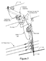
- FIG. 7 illustrates an example implementation of a coupling device according to an example embodiment of the present invention.
- FIG. 8 illustrates an example configuration of two air core inductors and a balun according to an example embodiment of the present invention.
- FIG. 1 shows an example embodiment of a portion of a power line communication system (PLCS) 104 .
- the PLCS 104 implements a communication network or sub-network using portions of the power system infrastructure 101 and various power line communication devices (PLCD) 138 , 139 , 135 .
- the PLCD 138 , 139 , 135 may be coupled to power lines 110 , 114 of the power system infrastructure 101 to transmit and receive communications.
- the power distribution system infrastructure 101 includes power lines, transformers and other devices for power generation, power transmission, and power delivery.
- a power source generates power, which is transmitted along high voltage (HV) power lines for long distances.
- HV high voltage
- Typical voltages found on HV transmission lines range from 69 kilovolts (kV) to in excess of 800 kV.
- the power signals are stepped down to medium voltage (MV) power signals at regional substation transformers.
- MV power lines 110 carry power signals through neighborhoods and populated areas. Typical voltages found on MV power lines 110 power range from about 1000 V to about 100 kV.
- the power signals are stepped down further to low voltage (LV) levels at distribution transformers.
- LV power lines 114 typically carry power signals having voltages ranging from about 100 V to about 600 V.
- a distribution transformer may function to distribute one, two, three, or more phase voltages to the customer premises, depending upon the demands of the user. In the United States, for example, these local distribution transformers typically feed anywhere from one to ten homes, depending upon the concentration of the customer premises in a particular area. Distribution transformers may be pole-top transformers located on a utility pole, pad-mounted transformers located on the ground, or transformers located under ground level.
- the PLCS 104 may provide user services, such as high speed broadband internet access, mobile telephone communications, broadband communications, streaming video and audio services, and other communication services to homes, buildings and other structures such as to each room, office, apartment, or other unit of multi-unit structures. Communication services also may be provided to mobile and stationary devices in outdoor areas such as customer premises yards, parks, stadiums, and also to public and semi-public indoor areas such as subway trains, subway stations, train stations, airports, restaurants, public and private automobiles, bodies of water (e.g., rivers, bays, inlets, etc.), building lobbies, elevators, etc.
- user services such as high speed broadband internet access, mobile telephone communications, broadband communications, streaming video and audio services, and other communication services to homes, buildings and other structures such as to each room, office, apartment, or other unit of multi-unit structures. Communication services also may be provided to mobile and stationary devices in outdoor areas such as customer premises yards, parks, stadiums, and also to public and semi-public indoor areas such as subway trains, subway stations, train stations, airports,
- the PLCS 104 may include one or more power line communication networks, such as an overhead power line communication network and/or an underground power line communication network.
- the PLCS 104 may include a plurality of communication nodes 128 which form communication links using power lines 110 , 114 and other communication media.
- Various user devices 130 and power line communication devices (PLCD) 138 , 139 , 135 may transmit and receive data over the links (including power line links, wireless links, fiber optic links, etc.) to communicate via an IP network 126 (e.g., the Internet).
- IP network 126 e.g., the Internet
- the data may be user data, control data, and/or power distribution parameter data.
- a communication node 128 may comprise a backhaul node 132 , an access node 134 , or a repeater node 135 .
- a given node 128 may serve as a backhaul node 132 , access node 134 , and/or repeater node 135 .
- the various nodes may include respective power line communication devices.
- a PLCD may be coupled to an MV power line 110 and/or an LV power line 114 .
- FIG. 2 shows a portion of a PLCS in which a power line communication device (PLCD) 202 is coupled to a single phase conductor 110 (which may form part of an overhead three-phase medium voltage (MV) power line) via a coupling device 204 , according to an example embodiment of the present invention.
- the PLCD 202 illustrated in FIG. 2 may be any of the PLCD 138 , 139 , 135 described herein, and may include a modem or other transceiver device 203 .
- the coupling device 204 may couple the PLCD 202 to the power line 110 at any point along the power line 110 . In some embodiments the coupling may occur in the vicinity of a distribution transformer 112 .
- This example embodiment includes a lightening arrestor 216 (also known as a surge arrestor) coupled on its first side to the MV power line phase conductor 110 and on its second side to a first end of an air core inductor 214 via a conductor 226 (e.g., a length of wire) at node 219 .
- the second end of the air core inductor 214 is connected to the neutral conductor 210 (which typically runs pole to pole in parallel with the MV power line 110 ) of the power distribution system, and which is also connected to earth ground via a ground conductor 224 .
- the coupler 204 may also include a balun 212 having a first winding 220 and a second winding 218 .
- Two terminals of the PLCD 202 may be coupled to the two ends of the second winding 218 of the balun 212 via a cable 222 .
- a first end 220 a of the first winding 220 of the balun 212 may be coupled to the neutral conductor 210 and the second end of the air core inductor 214 .
- the second end 220 b of the first winding 220 of the balun 212 may be coupled to the second end of the lightening arrestor 216 and the first end of the air core inductor 214 at node 219 .
- the second end 220 b of the first winding 220 is coupled to the lightening arrestor 216 via a conductor 226 but, alternately may be directly connected to the arrestor 216 at node 219 (and to the air core inductor 214 ) without a conductor 226 .
- the transceiver 203 of the PLCD 202 may be coupled to both ends of the air core inductor 214 via the cable 222 and the balun 212 .
- the air core inductor 214 may be connected in parallel with the first winding 220 of the balun 212 .
- the lightening arrestor 216 and air core inductor 215 are connected between the energized MV phase conductor 110 and the neutral conductor 210 .
- the data signals are communicated differentially in that the difference in voltage between the two wires (the MV phase conductor 110 and the neutral conductor 210 ) is used to convey information.
- the phase conductor carries the power line communication signal
- the neutral conductor carries the inverse of the same signal.
- distant radiated noise sources tend to add the same amount of noise (called common-mode noise) to both wires, causing the voltage difference between the conductors to remain substantially unchanged due to such noise.
- the power line communication system embodiments may have a lower susceptibility to distant radiated noise than some other systems.
- this embodiment of the coupler 204 may couple power line communications to one or more phases of a two phase, three phase or other multi-phase phase power line configuration systems.
- the lightening arrestor 216 of the present example and others described herein provides a capacitance that allows the data signals to pass through the arrestor 216 while preventing the low frequency (60 Hz) high voltage power carried by the power line 110 from being conducted therethrough to the neutral 210 .
- the lightening arrestor may be considered to be a high pass filter.
- One advantage of using a lightening arrestor is that they are already mass produced for utilities and, therefore, are relatively inexpensive compared to a custom designed capacitive device. Another advantage is that utility personnel are already familiar with installing them.
- the lightening arrestor 216 of this and the other embodiments described herein may be replaced with a high voltage capacitor (e.g., a capacitive device or a metal oxide varistor device).
- the air core inductor 214 provides an impedance to higher frequencies used to communicate data signals such as between 4 and 50 Megahertz but, (in this embodiment), is designed to allow electricity from a lightening strike to the MV power line conductor 110 to pass largely unimpeded.
- One example embodiment of the air core inductor 214 comprises a five micro-Henry air core inductor, which provides an impedance at frequencies used to communicate data signals, but that has very little impedance at frequencies often inherent in a lightening strike (e.g., 10 KHz). Hence, the air core inductor 214 may be considered a low pass filter.
- the impedance of the air core inductor 214 prevents higher frequency data signals received via the lightening arrestor 216 from being conducted directly to earth ground via conductor 224 and, instead, shunts the data signals through the first winding 220 of balun 218 to be received via second winding 218 by the modem 203 of PLCD 202 .
- the impedance of air core inductor 214 also prevents the data signals from canceling each other out at the first and second ends of the first winding 220 and instead, causes the data signals to be conducted to the MV phase conductor 110 (via lightening arrestor 216 ) and the neutral conductor 210 from the first winding 220 .
- the impedance i.e., low pass filter
- the impedance may be provided by other means such as by a ferrite core (or ferrite beads) placed around a conductor extending between the ends of the first winding 20 of the balun 212 .
- the air core inductor may have advantages over various other means in that it is easy to construct, is light weight, and economical to manufacture.
- Air core inductor as used herein, is meant to refer to an inductor having an inductance that is not substantially attributable to a magnetic material.
- the core of the inductor has a permeability approximating one and, therefore, may be formed of air, wood, fiber glass, copper, some types of steel, a dielectric, or other non-magnetic materials. Use of the air core inductor reduces the likelihood of saturation.
- the air core inductor 214 may be implemented in either a multi-phase system or a single phase system. Very low ‘through losses’ may be achieved with the coupler 204 embodiments, which may be controlled by the balun 212 . Specifically, in some embodiments, by increasing the input impedance of the balun 212 (from the first winding 220 ) may reduce the through loss (i.e., the reduction in energy) of signals that traverse the MV phase conductor 110 past the lightening arrestor 216 .
- coupler 204 is its compatibility with various power line cables and systems, including for example, 15, 25 and 35 kV cables and systems. Another advantage of the coupler 204 is that it can be installed without interrupting power line service, (i.e., no-outage installation).
- a communication signal is transmitted over the MV power line 110 from PLCD 202 .
- the communication signal is transmitted from the modem 203 of PLCD 202 to the second winding 218 of balun 212 .
- the communication signal is induced onto the first winding 220 .
- the air core inductor 214 has an impedance that directs the energy of the signal away from the inductor 214 , allowing the signal to be applied differentially to the energized phase conductor 110 (via the lightening arrestor 216 ) and the neutral conductor 210 .
- the signal may be transmitted differentially onto the phase conductor 110 and the neutral conductor 210 , and received by another PLCD 202 .
- the signals also may cross couple from one phase conductor 110 to another phase conductors 110 (not shown) through air.
- the transmitting PLCD 202 may be coupled to one conductor 110
- the receiving PLCD 202 may be coupled to the same conductor 110 or to a different conductor 110 .
- the communication signal may be received at the lightening arrestor, which conducts the high frequency signal to the first winding 220 of the balun 212 first, which induces the signal onto the second winding 218 , which is then detected at the PLCD 202 .
- the inverse of the signal may also be received via the neutral conductor 210 and received at the second end 220 a of the first winding 220 .
- the impedance of the air core inductor 214 causes the current of the two signals to flow through the first winding 220 of the balun 212 instead through the inductor 214 to cancel each other out.
- inductor 214 allows the lightening arrestor to simultaneously operate as both part of the coupling device and as a lightening arrestor to afford the utility infrastructure (e.g., a transformer) protection (because the air core inductor 214 will conduct the electricity of a lightening strike).
- utility infrastructure e.g., a transformer
- the dual functionality of some embodiments of the present invention may thus be well suited for some implementations of power line communication systems that include a coupling device at or near each transformer (as part of a bypass device to bypass data signals around the transformer).
- FIG. 3 a shows a portion of a PLCS in which a power line communication device (PLCD) 202 is coupled to a multi-phase medium voltage (MV) power line 110 via a coupling device 232 , according to another example embodiment of the present invention. Communications may be transmitted differentially over two MV power line phase conductors 110 a , 110 b to and from the PLCD 202 .
- the coupling device 232 may include a balun 234 , a pair of air core inductors 214 a,b , and a pair of lightening arrestors 216 a,b.
- a first air core inductor 214 a may be coupled to a first lightening arrestor 216 a (via a conductor 226 a ) between a first energized conductor 110 a and the neutral conductor 210 .
- a second air core inductor 214 b may be coupled to a second lightening arrestor 216 b (via conductor 226 b ) between a second energized conductor 110 b and the neutral conductor 210 .
- the balun 234 has a first winding 238 and a second winding 236 .
- first winding 238 may be coupled to a first node 219 a to which is connected to both the first air core inductor 214 a and the first lightening arrestor's 216 a .
- second end of the first winding 238 may be coupled to node 219 b to which is connected both the second air core inductor 214 b and the second lightening arrestor's 216 b .
- the lightening arrestors 216 may be replaced with other capacitive devices (e.g., a high voltage capacitor or a metal oxide varistor device).
- the two ends of the second winding 236 may be coupled to two terminals of the PLCD 202 , such as via a cable 222 .
- conductors 226 a and 226 b which each may comprise a length of copper wire, may be disposed along side of each other to form a two wire transmission line and thereby improve communications (e.g., by reducing radiated emissions from the coupler 232 ).
- the data signals are transmitted differentially over two phase conductors of a multi-phase power line (e.g., two phase or three phase).
- the air core inductors 214 a,b again provide an impedance to higher frequencies used to communicate data signals. Consequently, during transmission the air core inductors 214 prevent the data signals from being conducted to the neutral conductor and, instead, cause the data signals to be conducted through the lightening arrestors 216 a, b onto the two phase conductors 110 a,b .
- the air core inductors 214 prevent the data signals from being conducted to the neutral conductor 210 , but, instead, cause the data signals to be conducted from the lightening arrestors 216 , through the balun 234 , to the PLCD 202 .
- the air core inductors 214 have a very low impedance for frequencies often associated with lightening to thereby permit the current from a lightening strike on one of the MV conductors 110 a,b to be conducted to ground (via ground conductor 214 ) largely unimpeded.
- the first air core inductor 214 a and 214 b are connected to each other on their second ends, and are also connected to the neutral conductor 210 by a common conductor 317 (instead of via separate conductors as shown in FIG. 3 a ).
- the air core inductors 214 may be physically positioned adjacent the lightening arrestors 216 a,b on a utility pole so that the conductors 226 may not be present or, if present, may not form a two pair transmission line.
- phase conductors may not be available for implementing a differential communication method.
- the communication signal may be injected at two separate locations along the phase conductor.
- FIG. 4 shows a circuit 250 used to illustrate the principles of differential communication for such examples.
- Data signals (depicted as source Vs) split at point A and traverse along paths B and C toward transceiver 203 (whose gain equals one for the purposes of this description).
- the two paths B and C may be the same, except that path C may include an additional delay 25 of time duration T 1 that delays the arrival of the signal Vs at the negative input terminal of the transceiver 203 .
- Vs generally refers to the peak voltage of the voltage source, as opposed to the peak to peak voltage.
- the signal Vs will arrive at the positive terminal of the transceiver 203 at time T 1 before the signal Vs arrives at the negative terminal of the receiver.
- the transceiver 203 will see a voltage difference between its positive and negative terminals, and deliver an output voltage, that approximates twice Vs.
- the transceiver 90 will deliver an output voltage that approximates Vs multiplied by the square root of two.
- One method of causing a delay 25 along path C may be to increase the distance that the signal must travel to reach the transceiver 203 .
- One method of purposely implementing such a delay is to construct path C to be longer than path B by a distance equal to the portion of the wavelength for which a delay is desired.
- data from a single common source location may be transmitted and traverse two data paths on route to a common receiving location.
- a delay may be added to one path with a receiving device differentially receiving the signal from the two paths. If the delay for a given signal along one path is not ideal (e.g., is much less than the period), the differential voltage at the transceiver terminals may be smaller than Vs thereby resulting in an apparent coupling loss. However, depending on numerous factors some coupling loss may be tolerable or even desirable.
- the data signals (Vs) are transmitted along the MV power line from the left, as indicated by the arrow Vs.
- Vs the data signals
- the energy of the data signal will propagate down the power line toward point A.
- point A is a first connection point.
- a portion of the energy of the data signal will propagate along path Q and conductor 253 to the positive terminal of an isolation transformer 235 .
- a second portion of the energy of the data signal will continue propagating down the power line until reaching point B.
- point B is a second connection point to the power line 110 .
- a portion of the remaining energy of the data signal will propagate along path P and conductor 255 to the negative terminal of isolation transformer 235 .
- a third portion of the energy of the data signal may be reflected back by the real and present impedance discontinuity created by the junction at point B. This reflected power may contribute to both the insertion loss and through loss of a coupler 237 , because none of that power reaches the transceiver 203 , nor travels past the coupler 237 .
- the data signals traversing along path P must traverse a longer distance to reach the isolation transformer 235 than the data signals traveling along path A.
- the path distance between the isolation transformer 235 and point A may equal the path distance between the isolation transformer 235 and point B. Consequently, the additional distance that the data signals traverse along path P may substantially equal the distance d 1 between connections points A and B along the power line.
- the closer that the distance between points A and B approximates one-half a wavelength of the carrier signal used to communicate the data signals the closer the received signal will be to approximating twice Vs (i.e., twice Vs that exists at connection point A).
- Vs at point A may be less than the voltage transmitted from the transmitter due to the attenuation of the signal prior to it reaching point A.
- fuses 252 a , 252 b may be included to ensure safety of personnel in the event a fault occurs.
- the data signals are transmitted to the isolation transformer 235 resulting in a differential voltage Vin on the primary winding.
- the voltage Vin is conducted to the power line at connection points A and B.
- a portion of the power of the data signals may be transmitted in both directions on the power line away from the coupler 237 . Specifically, when the data signal from path P reaches point B, it will be travel in both directions along the MV power line. When a portion of that energy reaches point A, it will be added to the energy of the data signals that reach point A by traveling along path Q.
- the excess distance that the transmitted data signal travels along path P to reach point A, in comparison to the distance traveled along path Q to reach point A, may substantially equal the distance d 1 along the power line between points A and B. Accordingly, the more precisely that the distance between points A and B (or more exactly A+B+P ⁇ Q) approximates one-half the wavelength of the carrier signal used to communicate the data signals, the closer the transmitted signal (at point A) may approximate twice Vin (i.e., twice Vin transmitted by isolation transformer 235 ). In a system that uses multiple carrier frequencies, the distance between points A and B may approximate one-half the wavelength of any of the carrier frequencies. As will be evident those skilled in the art, transmission and reception of data signals to and from the other direction on the power line will operate in substantially the same manner.
- a half (or even quarter) of a wavelength may be too great a distance to make the coupler economically feasible or to permit a practical installation.
- the distance between the two connection point locations on the MV power (points A and B) preferably may be greater than five percent (5%), more preferably greater than seven and a half percent (7.5%), even more preferably greater than ten percent (10%), and still more preferably greater than twenty percent (20%) of the wavelength of a carrier frequency or of the lowest carrier frequency used to communicate the data signals.
- the wavelength is equal to the speed of propagation of the wave (which may approximate the speed of light) divided by its frequency.
- the distance between the two connection points may preferably be greater than five percent (5%), more preferably greater than seven and a half percent (7.5%), even more preferably greater than ten percent (10%), and still more preferably greater than twenty percent (20%) of the wavelength of the 30 Mhz carrier signal (i.e., the lowest carrier frequency). Because the 30 Mhz carrier signal has a wavelength of less than 394 inches on the MV wire, the distance between the two connection points may preferably be greater than 19.6 inches (5%), more preferably greater than 29.4 inches (7.5%), even more preferably greater than 39.2 inches (10%), and still more preferably greater than 78.4 inches (20%). It will be recognized to those skilled in the art that if the frequency band of carriers is very wide, in comparison to the lowest carrier frequency, it may be desirable to set the distance between the connection points to be a quarter of a wavelength of a carrier near the middle of the frequency band.
- FIG. 6 shows a portion 260 of a PLCS in which a power line communication device (PLCD) 202 is coupled to a single MV phase conductor 110 via the coupling device, according to another example embodiment of the present invention.
- This embodiment of the coupling device may include the same components as the coupling device of FIG. 3 a .
- the coupling device may include a balun 234 , a pair of lightening arrestors 216 , and a pair of air core inductors 214 a,b (or other high frequency impedance devices).
- a first air core inductor 214 a may be coupled to a first lightening arrestor 216 a (via a conductor 226 a ) between the energized conductor 110 and the neutral conductor 210 .
- a second air core inductor 214 b may be coupled to a second lightening arrestor 216 b (via conductor 226 b ) the energized conductor 110 and the neutral conductor 210 .
- the balun 234 has a first winding 238 and a second winding 236 .
- first winding 238 may be coupled to node 219 a to which is connected to both the first air core inductor 214 a and the first lightening arrestor's 216 a .
- second end of the first winding 238 may be coupled to node 219 b to which is connected both the second air core inductor 214 b and the second lightening arrestor's 216 b .
- the air core inductors 214 a and 214 b are connected to the neutral conductor on their second ends via separate conductors.
- This embodiment also includes the two wire transmission line formed by conductors 226 .
- the two air core inductors 214 could be connected to the neutral conductor 21 via a common conductor as illustrated in FIG. 3 b .
- the air core inductors 214 may be physically positioned adjacent the lightening arrestors 216 a,b so that the conductors 226 may not be present or, if present, may not form a two pair transmission line.
- the air core inductors 214 that form the high frequency impedances described above may be implemented in various embodiments.
- the air core inductors comprise an air core coil in the shape of a spiral that is formed of copper wire.
- Each loop of the spiral conductor may be insulated from other loops by a dielectric.
- the copper wire may have a rectangular cross section to thereby decrease the overall size of the inductor for a given inductance and DC current handling capability.
- the high frequency impedances of other embodiments of the coupler may be formed with other types of inductors and/or other low pass filters such as, for example, a copper wire that is looped one or more times through the center of a magnetically permeable toroid (e.g., a ferrite toroid).
- a magnetically permeable toroid e.g., a ferrite toroid
- FIG. 7 illustrates an example implementation of a single phase coupler similar to the embodiment shown in FIG. 2 .
- the air core inductor 214 and the balun 212 are housed inside a housing that is attached to a bracket assembly.
- the lightening arrestor 216 is also attached to the bracket assembly so that mounting of the bracket assembly provides the physical installation of the components of the coupler.
- two air core inductors 214 may be disposed in the housing and two arrestors may be attached to the bracket assembly.
- FIG. 8 illustrates the configuration of two air core inductors 214 a,b that are to be mounted inside such a housing.
- the two air core inductors 214 of this embodiment are formed of a copper conductor having spiral configuration.
- the first ends ( 214 c and 214 d ) of each air core inductor 214 a,b are connected to the balun 234 and also connected to the second ends of the lightening arrestors (not shown) via bolt that extends through the housing and is exposed on the opposite site of the housing.
- the second ends of the air core conductors are connected together and also connected to connector 317 a , which is to be connected to conductor 317 (shown in FIG. 3 b ), which connects to the neutral conductor 210 .
- Other implementations and configurations for mounting the coupler and housing the components are within the scope of the present invention.
- the power line communication system 104 may include communication links formed between communication nodes 128 over a communication medium. Some links may be formed over the MV power lines 110 . Some links may be formed over LV power lines 114 . Other links may be gigabit-Ethernet links 152 , 154 formed, for example, using a fiber optic cable. Thus, some links may be formed using a portion 101 of the power system infrastructure, while other links may be formed over another communication media, (e.g., a coaxial cable, a T-1 line, a fiber optic cable, wirelessly (e.g., IEEE 802.11a/b/g, 802.16, 1G, 2G, 3G, or satellite such as WildBlue®)). The links formed by wired or wireless media may occur at any point along a communication path between a backhaul node 132 and a user device 130 .
- the links formed by wired or wireless media may occur at any point along a communication path between a backhaul node 132 and a user device 130 .
- Each communication node 128 may be formed by one or more communication devices.
- Communication nodes which communicate over a power line medium include a power line communication device (PLCD).
- Exemplary PLCD include a backhaul device 138 , an access device 139 , and a repeater.
- Communication nodes which communicate wirelessly may include a mobile telephone cell site or a wireless access point having at least a wireless transceiver.
- Communication nodes which communicate over a coaxial cable may include a cable modem.
- Communication nodes which communicate over a twisted pair wire may include a DSL modem or other modem.
- a given communication node typically will communicate in two directions (either full duplex or half duplex), which may be over the same or different types of communication media. Accordingly, a communication node 128 may include one, two or more communication devices.
- a backhaul node 132 may serve as an interface between a power line portion (e.g., an MV power line 110 ) of the system 104 and an upstream node, which may be, for example, an aggregation point 124 that may provide a connection to an IP network 126 .
- the backhaul node 132 may communicate with its upstream device via any of several alternative communication media, such as a fiber optic (digital or analog (e.g., Wave Division Multiplexed), coaxial cable, WiMAX, IEEE, 802.11, twisted pair and/or another wired or wireless media.
- Downstream communications from the IP network 126 typically are communicated through the aggregation point 124 to the backhaul node 132 .
- the aggregation point 124 typically includes an Internet Protocol (IP) network data packet router and is connected to an IP network backbone, thereby providing access to an IP network 126 (i.e., can be connected to or form part of a point of presence or POP). Any available mechanism may be used to link the aggregation point 124 to the POP or other device (e.g., fiber optic conductors, T-carrier, Synchronous Optical Network (SONET), and wireless techniques).
- a backhaul node may include a first modem for communicating over a fiber optic conductor, a second modem for communicating over an MV power line, a third modem for communicating with one or more user devices such as over a low voltage power line or wirelessly.
- a backhaul node may include a processor and a routing device (e.g., router, bridge, switch, etc.) to control the destination of received data packets.
- An access node 134 may serve one or more user devices 130 or other network destinations. Upstream data may be sent, for example, from a user device 130 to an access node 134 . Other data also, such as power line parameter data (e.g., from parameter sensing devices) may be received by an access node's power line communication device 139 . The data enters the network 104 along a communication medium coupled to an access node 134 . The data is routed through the network 104 to a backhaul node 132 , (or a local destination, such as another user device 130 ). Downstream data is sent through the network 104 to a user device 130 .
- power line parameter data e.g., from parameter sensing devices
- an access node may include a first for communicating over an MV power line (via a coupler), a second modem for communicating with one or more user devices such as over a low voltage power line or wirelessly.
- an access node may include a processor and a routing device (e.g., router, bridge, switch, etc.) to control the destination of received data packets.
- Exemplary user devices 130 include a computer 130 a , LAN, a WLAN, router 130 b , Voice-over IP endpoint, game system, personal digital assistant (PDA), mobile telephone, digital cable box, power meter, gas meter, water meter, security system, alarm system (e.g., fire, smoke, carbon dioxide, security/burglar, etc.), stereo system, television, fax machine 130 c , HomePlug residential network, or other device having a data interface.
- a user device 130 may include or be coupled to a modem to communicate with a given access node 134 .
- Exemplary modems include a power line modem 136 , a wireless modem 131 , a cable modem, a DSL modem or other suitable transceiver device.
- a repeater node 135 may receive and re-transmit data (i.e., repeat), for example, to extend the communications range of other communication elements.
- backhaul nodes 132 and access nodes 134 also may serve as repeater nodes 135 , (e.g., for other access nodes and other backhaul nodes 132 ).
- Repeaters may also be stand-alone devices without additional functionality.
- Repeaters 135 may be coupled to and repeat data on MV power lines or LV power lines (and, for the latter, be coupled to the internal or external LV power lines).
- Communication nodes which access a link over a wireless medium may include a wireless access point having at least a wireless transceiver or a mobile telephone cell site (e.g., a micro or pico cell site).
- Communication nodes which access a link over a coaxial cable may include a cable modem.
- Communication nodes which access a link over a T-1 wire may include a DSL modem.
- a backhaul device 138 or access device 139 or repeater may establish links over MV power lines 110 , LV power lines 114 , wired media, and wireless media. Accordingly, a given communication node may communicate along two or more directions establishing multiple communication links, which may be formed along the same or different types of communication media.
- the communication nodes with which the coupling devices of the present invention are used may be configured to determine when a lightening arrestor 216 that is forming part of the coupling device has been blown, which, for example, may be caused by a lightening strike. For example, if communications with a particular PLCD are no longer possible from other PLCDs, the arrestor 216 may be faulted. Different arrestors may fault differently. Consequently, communications may remain possible with some other arrestors even after the arrestor is blown due to a lightening strike. In such causes, the electrical characteristics (e.g., the capacitance and/or resistance) of the faulted lightening arrestor may be different from the characteristics of the arrestor before it was blown.
- the electrical characteristics e.g., the capacitance and/or resistance
- the change in the characteristics may cause a change in the transfer function of the arrestor for frequencies of communications, which in turn may cause an increase in insertion loss and a reduction bandwidth.
- Detection of a blown lightening arrestor by a PLCD may result in transmission of a notification by the PLCD to its upstream device, through the internet, to a remote computer system, which stores information of the location (e.g., pole number) of the blown arrestor in order to dispatch crews to replace the arrestor.
- the couplers of the present invention may also be used with existing arrestors that are already installed.
- one process may comprise identifying installed arrestors and installing the air core inductor, balun, and PLCD.
- the communication network 104 may provide high speed internet access and other high data-rate data services to user devices, homes, buildings and other structure, and to each room, office, apartment, or other unit or sub-unit of multi-unit structure. In doing so, a communication link is formed between two communication nodes 128 over a communication medium. Some links are formed by using a portion 101 of the power system infrastructure. Specifically, some links are formed over MV power lines 110 , and other links are formed over LV power lines 114 .
- Still other links may be formed over another communication media, (e.g., a coaxial cable, a T-1 line, a fiber optic cable, wirelessly (e.g., IEEE 802.11a/b/g, 802.16, 1G, 2G, 3G, or satellite such as WildBlue®)).
- Some links may comprise wired Ethernet, multipoint microwave distribution system (MMDS) standards, DOCSIS (Data Over Cable System Interface Specification) signal standards or another suitable communication method.
- MMDS multipoint microwave distribution system
- DOCSIS Data Over Cable System Interface Specification
- frequency bands are used that are selected from among ranges of licensed frequency bands (e.g., 6 GHz, 11 GHz, 18 GHz, 23 GHz, 24 GHz, 28 GHz, or 38 GHz band) and unlicensed frequency bands (e.g., 900 MHz, 2.4 GHz, 5.8 GHz, 24 GHz, 38 GHz, or 60 GHz (i.e., 57-64 GHz)).
- licensed frequency bands e.g., 6 GHz, 11 GHz, 18 GHz, 23 GHz, 24 GHz, 28 GHz, or 38 GHz band
- unlicensed frequency bands e.g., 900 MHz, 2.4 GHz, 5.8 GHz, 24 GHz, 38 GHz, or 60 GHz (i.e., 57-64 GHz)
- the communication network 104 includes links that may be formed by power lines, non-power line wired media, and wireless media.
- the links may occur at any point along a communication path between a backhaul node 132 and a user device 130 , or between a backhaul node 132 and a distribution point 127 or aggregation point 124 .
- the nodes 128 may use time division multiplexing and implement one or more layers of the 7 layer open systems interconnection (OSI) model.
- OSI open systems interconnection
- the devices and software may implement switching and routing technologies, and create logical paths, known as virtual circuits, for transmitting data from node to node.
- error handling, congestion control and packet sequencing can be performed at Layer 3.
- Layer 2 ‘data link’ activities include encoding and decoding data packets and handling errors of the ‘physical’ layer 1, along with flow control and frame synchronization.
- the configuration of the various communication nodes may vary.
- the nodes coupled to power lines may include a modem that is substantially compatible with the HomePlug 1.0 or A/V standard.
- the communications among nodes may be time division multiple access or frequency division multiple access.
Landscapes
- Engineering & Computer Science (AREA)
- Power Engineering (AREA)
- Computer Networks & Wireless Communication (AREA)
- Signal Processing (AREA)
- Cable Transmission Systems, Equalization Of Radio And Reduction Of Echo (AREA)
Abstract
Description
Claims (26)
Priority Applications (2)
| Application Number | Priority Date | Filing Date | Title |
|---|---|---|---|
| US11/768,871 US7795994B2 (en) | 2007-06-26 | 2007-06-26 | Power line coupling device and method |
| US12/016,390 US7876174B2 (en) | 2007-06-26 | 2008-01-18 | Power line coupling device and method |
Applications Claiming Priority (1)
| Application Number | Priority Date | Filing Date | Title |
|---|---|---|---|
| US11/768,871 US7795994B2 (en) | 2007-06-26 | 2007-06-26 | Power line coupling device and method |
Related Child Applications (1)
| Application Number | Title | Priority Date | Filing Date |
|---|---|---|---|
| US12/016,390 Continuation-In-Part US7876174B2 (en) | 2007-06-26 | 2008-01-18 | Power line coupling device and method |
Publications (2)
| Publication Number | Publication Date |
|---|---|
| US20090002094A1 US20090002094A1 (en) | 2009-01-01 |
| US7795994B2 true US7795994B2 (en) | 2010-09-14 |
Family
ID=40159681
Family Applications (1)
| Application Number | Title | Priority Date | Filing Date |
|---|---|---|---|
| US11/768,871 Active 2028-09-06 US7795994B2 (en) | 2007-06-26 | 2007-06-26 | Power line coupling device and method |
Country Status (1)
| Country | Link |
|---|---|
| US (1) | US7795994B2 (en) |
Cited By (181)
| Publication number | Priority date | Publication date | Assignee | Title |
|---|---|---|---|---|
| US20090065597A1 (en) * | 2005-12-12 | 2009-03-12 | Garozzo James P | Low voltage power line communication for climate control system |
| US20090134699A1 (en) * | 2007-11-23 | 2009-05-28 | Korea Electro Technology Research Institute | Signal Coupling Apparatus For Power Line Communications Using A Three-Phase Four-Wire Power Line |
| US20120201312A1 (en) * | 2011-02-07 | 2012-08-09 | Sony Corporation | Power line communication apparatus including ac power socket |
| US20150162988A1 (en) * | 2013-12-10 | 2015-06-11 | At&T Intellectual Property I, L.P. | Quasi-optical coupler |
| US9119127B1 (en) | 2012-12-05 | 2015-08-25 | At&T Intellectual Property I, Lp | Backhaul link for distributed antenna system |
| US9154966B2 (en) | 2013-11-06 | 2015-10-06 | At&T Intellectual Property I, Lp | Surface-wave communications and methods thereof |
| US9182429B2 (en) | 2012-01-04 | 2015-11-10 | Sentient Energy, Inc. | Distribution line clamp force using DC bias on coil |
| US9229036B2 (en) | 2012-01-03 | 2016-01-05 | Sentient Energy, Inc. | Energy harvest split core design elements for ease of installation, high performance, and long term reliability |
| US9312919B1 (en) | 2014-10-21 | 2016-04-12 | At&T Intellectual Property I, Lp | Transmission device with impairment compensation and methods for use therewith |
| US9461706B1 (en) | 2015-07-31 | 2016-10-04 | At&T Intellectual Property I, Lp | Method and apparatus for exchanging communication signals |
| US9490869B1 (en) | 2015-05-14 | 2016-11-08 | At&T Intellectual Property I, L.P. | Transmission medium having multiple cores and methods for use therewith |
| US9503189B2 (en) | 2014-10-10 | 2016-11-22 | At&T Intellectual Property I, L.P. | Method and apparatus for arranging communication sessions in a communication system |
| US9509415B1 (en) | 2015-06-25 | 2016-11-29 | At&T Intellectual Property I, L.P. | Methods and apparatus for inducing a fundamental wave mode on a transmission medium |
| US9520945B2 (en) | 2014-10-21 | 2016-12-13 | At&T Intellectual Property I, L.P. | Apparatus for providing communication services and methods thereof |
| US9525524B2 (en) | 2013-05-31 | 2016-12-20 | At&T Intellectual Property I, L.P. | Remote distributed antenna system |
| US9525210B2 (en) | 2014-10-21 | 2016-12-20 | At&T Intellectual Property I, L.P. | Guided-wave transmission device with non-fundamental mode propagation and methods for use therewith |
| US9531427B2 (en) | 2014-11-20 | 2016-12-27 | At&T Intellectual Property I, L.P. | Transmission device with mode division multiplexing and methods for use therewith |
| US9564947B2 (en) | 2014-10-21 | 2017-02-07 | At&T Intellectual Property I, L.P. | Guided-wave transmission device with diversity and methods for use therewith |
| US9577307B2 (en) | 2014-10-21 | 2017-02-21 | At&T Intellectual Property I, L.P. | Guided-wave transmission device and methods for use therewith |
| US9608692B2 (en) | 2015-06-11 | 2017-03-28 | At&T Intellectual Property I, L.P. | Repeater and methods for use therewith |
| US9608740B2 (en) | 2015-07-15 | 2017-03-28 | At&T Intellectual Property I, L.P. | Method and apparatus for launching a wave mode that mitigates interference |
| US9615269B2 (en) | 2014-10-02 | 2017-04-04 | At&T Intellectual Property I, L.P. | Method and apparatus that provides fault tolerance in a communication network |
| US9628116B2 (en) | 2015-07-14 | 2017-04-18 | At&T Intellectual Property I, L.P. | Apparatus and methods for transmitting wireless signals |
| US9628854B2 (en) | 2014-09-29 | 2017-04-18 | At&T Intellectual Property I, L.P. | Method and apparatus for distributing content in a communication network |
| US9640850B2 (en) | 2015-06-25 | 2017-05-02 | At&T Intellectual Property I, L.P. | Methods and apparatus for inducing a non-fundamental wave mode on a transmission medium |
| US9654173B2 (en) | 2014-11-20 | 2017-05-16 | At&T Intellectual Property I, L.P. | Apparatus for powering a communication device and methods thereof |
| US9653770B2 (en) | 2014-10-21 | 2017-05-16 | At&T Intellectual Property I, L.P. | Guided wave coupler, coupling module and methods for use therewith |
| US9667317B2 (en) | 2015-06-15 | 2017-05-30 | At&T Intellectual Property I, L.P. | Method and apparatus for providing security using network traffic adjustments |
| US9680670B2 (en) | 2014-11-20 | 2017-06-13 | At&T Intellectual Property I, L.P. | Transmission device with channel equalization and control and methods for use therewith |
| US9685992B2 (en) | 2014-10-03 | 2017-06-20 | At&T Intellectual Property I, L.P. | Circuit panel network and methods thereof |
| US9692101B2 (en) | 2014-08-26 | 2017-06-27 | At&T Intellectual Property I, L.P. | Guided wave couplers for coupling electromagnetic waves between a waveguide surface and a surface of a wire |
| US9705571B2 (en) | 2015-09-16 | 2017-07-11 | At&T Intellectual Property I, L.P. | Method and apparatus for use with a radio distributed antenna system |
| US9705561B2 (en) | 2015-04-24 | 2017-07-11 | At&T Intellectual Property I, L.P. | Directional coupling device and methods for use therewith |
| US9722318B2 (en) | 2015-07-14 | 2017-08-01 | At&T Intellectual Property I, L.P. | Method and apparatus for coupling an antenna to a device |
| US9729197B2 (en) | 2015-10-01 | 2017-08-08 | At&T Intellectual Property I, L.P. | Method and apparatus for communicating network management traffic over a network |
| US9735833B2 (en) | 2015-07-31 | 2017-08-15 | At&T Intellectual Property I, L.P. | Method and apparatus for communications management in a neighborhood network |
| US9742462B2 (en) | 2014-12-04 | 2017-08-22 | At&T Intellectual Property I, L.P. | Transmission medium and communication interfaces and methods for use therewith |
| US9748626B2 (en) | 2015-05-14 | 2017-08-29 | At&T Intellectual Property I, L.P. | Plurality of cables having different cross-sectional shapes which are bundled together to form a transmission medium |
| US9749013B2 (en) | 2015-03-17 | 2017-08-29 | At&T Intellectual Property I, L.P. | Method and apparatus for reducing attenuation of electromagnetic waves guided by a transmission medium |
| US9749053B2 (en) | 2015-07-23 | 2017-08-29 | At&T Intellectual Property I, L.P. | Node device, repeater and methods for use therewith |
| US9755697B2 (en) | 2014-09-15 | 2017-09-05 | At&T Intellectual Property I, L.P. | Method and apparatus for sensing a condition in a transmission medium of electromagnetic waves |
| US9762289B2 (en) | 2014-10-14 | 2017-09-12 | At&T Intellectual Property I, L.P. | Method and apparatus for transmitting or receiving signals in a transportation system |
| US9769128B2 (en) | 2015-09-28 | 2017-09-19 | At&T Intellectual Property I, L.P. | Method and apparatus for encryption of communications over a network |
| US9769020B2 (en) | 2014-10-21 | 2017-09-19 | At&T Intellectual Property I, L.P. | Method and apparatus for responding to events affecting communications in a communication network |
| US9780834B2 (en) | 2014-10-21 | 2017-10-03 | At&T Intellectual Property I, L.P. | Method and apparatus for transmitting electromagnetic waves |
| US9793955B2 (en) | 2015-04-24 | 2017-10-17 | At&T Intellectual Property I, Lp | Passive electrical coupling device and methods for use therewith |
| US9793954B2 (en) | 2015-04-28 | 2017-10-17 | At&T Intellectual Property I, L.P. | Magnetic coupling device and methods for use therewith |
| US9793951B2 (en) | 2015-07-15 | 2017-10-17 | At&T Intellectual Property I, L.P. | Method and apparatus for launching a wave mode that mitigates interference |
| US9800327B2 (en) | 2014-11-20 | 2017-10-24 | At&T Intellectual Property I, L.P. | Apparatus for controlling operations of a communication device and methods thereof |
| US9820146B2 (en) | 2015-06-12 | 2017-11-14 | At&T Intellectual Property I, L.P. | Method and apparatus for authentication and identity management of communicating devices |
| US9836957B2 (en) | 2015-07-14 | 2017-12-05 | At&T Intellectual Property I, L.P. | Method and apparatus for communicating with premises equipment |
| US9838896B1 (en) | 2016-12-09 | 2017-12-05 | At&T Intellectual Property I, L.P. | Method and apparatus for assessing network coverage |
| US9847850B2 (en) | 2014-10-14 | 2017-12-19 | At&T Intellectual Property I, L.P. | Method and apparatus for adjusting a mode of communication in a communication network |
| US9847566B2 (en) | 2015-07-14 | 2017-12-19 | At&T Intellectual Property I, L.P. | Method and apparatus for adjusting a field of a signal to mitigate interference |
| US9853342B2 (en) | 2015-07-14 | 2017-12-26 | At&T Intellectual Property I, L.P. | Dielectric transmission medium connector and methods for use therewith |
| US9860075B1 (en) | 2016-08-26 | 2018-01-02 | At&T Intellectual Property I, L.P. | Method and communication node for broadband distribution |
| US9865911B2 (en) | 2015-06-25 | 2018-01-09 | At&T Intellectual Property I, L.P. | Waveguide system for slot radiating first electromagnetic waves that are combined into a non-fundamental wave mode second electromagnetic wave on a transmission medium |
| US9866309B2 (en) | 2015-06-03 | 2018-01-09 | At&T Intellectual Property I, Lp | Host node device and methods for use therewith |
| US9871282B2 (en) | 2015-05-14 | 2018-01-16 | At&T Intellectual Property I, L.P. | At least one transmission medium having a dielectric surface that is covered at least in part by a second dielectric |
| US9871283B2 (en) | 2015-07-23 | 2018-01-16 | At&T Intellectual Property I, Lp | Transmission medium having a dielectric core comprised of plural members connected by a ball and socket configuration |
| US9876264B2 (en) | 2015-10-02 | 2018-01-23 | At&T Intellectual Property I, Lp | Communication system, guided wave switch and methods for use therewith |
| US9876571B2 (en) | 2015-02-20 | 2018-01-23 | At&T Intellectual Property I, Lp | Guided-wave transmission device with non-fundamental mode propagation and methods for use therewith |
| US9876605B1 (en) | 2016-10-21 | 2018-01-23 | At&T Intellectual Property I, L.P. | Launcher and coupling system to support desired guided wave mode |
| US9882257B2 (en) | 2015-07-14 | 2018-01-30 | At&T Intellectual Property I, L.P. | Method and apparatus for launching a wave mode that mitigates interference |
| US9882277B2 (en) | 2015-10-02 | 2018-01-30 | At&T Intellectual Property I, Lp | Communication device and antenna assembly with actuated gimbal mount |
| US9893795B1 (en) | 2016-12-07 | 2018-02-13 | At&T Intellectual Property I, Lp | Method and repeater for broadband distribution |
| US9906269B2 (en) | 2014-09-17 | 2018-02-27 | At&T Intellectual Property I, L.P. | Monitoring and mitigating conditions in a communication network |
| US9904535B2 (en) | 2015-09-14 | 2018-02-27 | At&T Intellectual Property I, L.P. | Method and apparatus for distributing software |
| US9911020B1 (en) | 2016-12-08 | 2018-03-06 | At&T Intellectual Property I, L.P. | Method and apparatus for tracking via a radio frequency identification device |
| US9913139B2 (en) | 2015-06-09 | 2018-03-06 | At&T Intellectual Property I, L.P. | Signal fingerprinting for authentication of communicating devices |
| US9912027B2 (en) | 2015-07-23 | 2018-03-06 | At&T Intellectual Property I, L.P. | Method and apparatus for exchanging communication signals |
| US9912419B1 (en) | 2016-08-24 | 2018-03-06 | At&T Intellectual Property I, L.P. | Method and apparatus for managing a fault in a distributed antenna system |
| US9912381B2 (en) | 2015-06-03 | 2018-03-06 | At&T Intellectual Property I, Lp | Network termination and methods for use therewith |
| US9917341B2 (en) | 2015-05-27 | 2018-03-13 | At&T Intellectual Property I, L.P. | Apparatus and method for launching electromagnetic waves and for modifying radial dimensions of the propagating electromagnetic waves |
| US9927517B1 (en) | 2016-12-06 | 2018-03-27 | At&T Intellectual Property I, L.P. | Apparatus and methods for sensing rainfall |
| US9948354B2 (en) | 2015-04-28 | 2018-04-17 | At&T Intellectual Property I, L.P. | Magnetic coupling device with reflective plate and methods for use therewith |
| US9948333B2 (en) | 2015-07-23 | 2018-04-17 | At&T Intellectual Property I, L.P. | Method and apparatus for wireless communications to mitigate interference |
| US9954287B2 (en) | 2014-11-20 | 2018-04-24 | At&T Intellectual Property I, L.P. | Apparatus for converting wireless signals and electromagnetic waves and methods thereof |
| US9954354B2 (en) | 2015-01-06 | 2018-04-24 | Sentient Energy, Inc. | Methods and apparatus for mitigation of damage of power line assets from traveling electrical arcs |
| US9967173B2 (en) | 2015-07-31 | 2018-05-08 | At&T Intellectual Property I, L.P. | Method and apparatus for authentication and identity management of communicating devices |
| US9973940B1 (en) | 2017-02-27 | 2018-05-15 | At&T Intellectual Property I, L.P. | Apparatus and methods for dynamic impedance matching of a guided wave launcher |
| US9984818B2 (en) | 2015-12-04 | 2018-05-29 | Sentient Energy, Inc. | Current harvesting transformer with protection from high currents |
| US9991580B2 (en) | 2016-10-21 | 2018-06-05 | At&T Intellectual Property I, L.P. | Launcher and coupling system for guided wave mode cancellation |
| US9998870B1 (en) | 2016-12-08 | 2018-06-12 | At&T Intellectual Property I, L.P. | Method and apparatus for proximity sensing |
| US9999038B2 (en) | 2013-05-31 | 2018-06-12 | At&T Intellectual Property I, L.P. | Remote distributed antenna system |
| US9997819B2 (en) | 2015-06-09 | 2018-06-12 | At&T Intellectual Property I, L.P. | Transmission medium and method for facilitating propagation of electromagnetic waves via a core |
| US10009901B2 (en) | 2015-09-16 | 2018-06-26 | At&T Intellectual Property I, L.P. | Method, apparatus, and computer-readable storage medium for managing utilization of wireless resources between base stations |
| US10009063B2 (en) | 2015-09-16 | 2018-06-26 | At&T Intellectual Property I, L.P. | Method and apparatus for use with a radio distributed antenna system having an out-of-band reference signal |
| US10009065B2 (en) | 2012-12-05 | 2018-06-26 | At&T Intellectual Property I, L.P. | Backhaul link for distributed antenna system |
| US10009067B2 (en) | 2014-12-04 | 2018-06-26 | At&T Intellectual Property I, L.P. | Method and apparatus for configuring a communication interface |
| US10020844B2 (en) | 2016-12-06 | 2018-07-10 | T&T Intellectual Property I, L.P. | Method and apparatus for broadcast communication via guided waves |
| US10020587B2 (en) | 2015-07-31 | 2018-07-10 | At&T Intellectual Property I, L.P. | Radial antenna and methods for use therewith |
| US10027397B2 (en) | 2016-12-07 | 2018-07-17 | At&T Intellectual Property I, L.P. | Distributed antenna system and methods for use therewith |
| US10033108B2 (en) | 2015-07-14 | 2018-07-24 | At&T Intellectual Property I, L.P. | Apparatus and methods for generating an electromagnetic wave having a wave mode that mitigates interference |
| US10033107B2 (en) | 2015-07-14 | 2018-07-24 | At&T Intellectual Property I, L.P. | Method and apparatus for coupling an antenna to a device |
| US10044409B2 (en) | 2015-07-14 | 2018-08-07 | At&T Intellectual Property I, L.P. | Transmission medium and methods for use therewith |
| US10051629B2 (en) | 2015-09-16 | 2018-08-14 | At&T Intellectual Property I, L.P. | Method and apparatus for use with a radio distributed antenna system having an in-band reference signal |
| US10051483B2 (en) | 2015-10-16 | 2018-08-14 | At&T Intellectual Property I, L.P. | Method and apparatus for directing wireless signals |
| US10069535B2 (en) | 2016-12-08 | 2018-09-04 | At&T Intellectual Property I, L.P. | Apparatus and methods for launching electromagnetic waves having a certain electric field structure |
| US10074890B2 (en) | 2015-10-02 | 2018-09-11 | At&T Intellectual Property I, L.P. | Communication device and antenna with integrated light assembly |
| US10079661B2 (en) | 2015-09-16 | 2018-09-18 | At&T Intellectual Property I, L.P. | Method and apparatus for use with a radio distributed antenna system having a clock reference |
| US10090606B2 (en) | 2015-07-15 | 2018-10-02 | At&T Intellectual Property I, L.P. | Antenna system with dielectric array and methods for use therewith |
| US10090594B2 (en) | 2016-11-23 | 2018-10-02 | At&T Intellectual Property I, L.P. | Antenna system having structural configurations for assembly |
| US10103801B2 (en) | 2015-06-03 | 2018-10-16 | At&T Intellectual Property I, L.P. | Host node device and methods for use therewith |
| US10103422B2 (en) | 2016-12-08 | 2018-10-16 | At&T Intellectual Property I, L.P. | Method and apparatus for mounting network devices |
| US10135146B2 (en) | 2016-10-18 | 2018-11-20 | At&T Intellectual Property I, L.P. | Apparatus and methods for launching guided waves via circuits |
| US10136434B2 (en) | 2015-09-16 | 2018-11-20 | At&T Intellectual Property I, L.P. | Method and apparatus for use with a radio distributed antenna system having an ultra-wideband control channel |
| US10135147B2 (en) | 2016-10-18 | 2018-11-20 | At&T Intellectual Property I, L.P. | Apparatus and methods for launching guided waves via an antenna |
| US10135145B2 (en) | 2016-12-06 | 2018-11-20 | At&T Intellectual Property I, L.P. | Apparatus and methods for generating an electromagnetic wave along a transmission medium |
| US10142086B2 (en) | 2015-06-11 | 2018-11-27 | At&T Intellectual Property I, L.P. | Repeater and methods for use therewith |
| US10139820B2 (en) | 2016-12-07 | 2018-11-27 | At&T Intellectual Property I, L.P. | Method and apparatus for deploying equipment of a communication system |
| US10144036B2 (en) | 2015-01-30 | 2018-12-04 | At&T Intellectual Property I, L.P. | Method and apparatus for mitigating interference affecting a propagation of electromagnetic waves guided by a transmission medium |
| US10148016B2 (en) | 2015-07-14 | 2018-12-04 | At&T Intellectual Property I, L.P. | Apparatus and methods for communicating utilizing an antenna array |
| US10154493B2 (en) | 2015-06-03 | 2018-12-11 | At&T Intellectual Property I, L.P. | Network termination and methods for use therewith |
| US10168695B2 (en) | 2016-12-07 | 2019-01-01 | At&T Intellectual Property I, L.P. | Method and apparatus for controlling an unmanned aircraft |
| US10170840B2 (en) | 2015-07-14 | 2019-01-01 | At&T Intellectual Property I, L.P. | Apparatus and methods for sending or receiving electromagnetic signals |
| US10178445B2 (en) | 2016-11-23 | 2019-01-08 | At&T Intellectual Property I, L.P. | Methods, devices, and systems for load balancing between a plurality of waveguides |
| US10205655B2 (en) | 2015-07-14 | 2019-02-12 | At&T Intellectual Property I, L.P. | Apparatus and methods for communicating utilizing an antenna array and multiple communication paths |
| US10224634B2 (en) | 2016-11-03 | 2019-03-05 | At&T Intellectual Property I, L.P. | Methods and apparatus for adjusting an operational characteristic of an antenna |
| US10225025B2 (en) | 2016-11-03 | 2019-03-05 | At&T Intellectual Property I, L.P. | Method and apparatus for detecting a fault in a communication system |
| US10243784B2 (en) | 2014-11-20 | 2019-03-26 | At&T Intellectual Property I, L.P. | System for generating topology information and methods thereof |
| US10243270B2 (en) | 2016-12-07 | 2019-03-26 | At&T Intellectual Property I, L.P. | Beam adaptive multi-feed dielectric antenna system and methods for use therewith |
| US10264586B2 (en) | 2016-12-09 | 2019-04-16 | At&T Mobility Ii Llc | Cloud-based packet controller and methods for use therewith |
| US10291334B2 (en) | 2016-11-03 | 2019-05-14 | At&T Intellectual Property I, L.P. | System for detecting a fault in a communication system |
| US10291311B2 (en) | 2016-09-09 | 2019-05-14 | At&T Intellectual Property I, L.P. | Method and apparatus for mitigating a fault in a distributed antenna system |
| US10298293B2 (en) | 2017-03-13 | 2019-05-21 | At&T Intellectual Property I, L.P. | Apparatus of communication utilizing wireless network devices |
| US10305190B2 (en) | 2016-12-01 | 2019-05-28 | At&T Intellectual Property I, L.P. | Reflecting dielectric antenna system and methods for use therewith |
| US10312567B2 (en) | 2016-10-26 | 2019-06-04 | At&T Intellectual Property I, L.P. | Launcher with planar strip antenna and methods for use therewith |
| US10320586B2 (en) | 2015-07-14 | 2019-06-11 | At&T Intellectual Property I, L.P. | Apparatus and methods for generating non-interfering electromagnetic waves on an insulated transmission medium |
| US10326494B2 (en) | 2016-12-06 | 2019-06-18 | At&T Intellectual Property I, L.P. | Apparatus for measurement de-embedding and methods for use therewith |
| US10326689B2 (en) | 2016-12-08 | 2019-06-18 | At&T Intellectual Property I, L.P. | Method and system for providing alternative communication paths |
| US10340983B2 (en) | 2016-12-09 | 2019-07-02 | At&T Intellectual Property I, L.P. | Method and apparatus for surveying remote sites via guided wave communications |
| US10340603B2 (en) | 2016-11-23 | 2019-07-02 | At&T Intellectual Property I, L.P. | Antenna system having shielded structural configurations for assembly |
| US10340600B2 (en) | 2016-10-18 | 2019-07-02 | At&T Intellectual Property I, L.P. | Apparatus and methods for launching guided waves via plural waveguide systems |
| US10340601B2 (en) | 2016-11-23 | 2019-07-02 | At&T Intellectual Property I, L.P. | Multi-antenna system and methods for use therewith |
| US10341142B2 (en) | 2015-07-14 | 2019-07-02 | At&T Intellectual Property I, L.P. | Apparatus and methods for generating non-interfering electromagnetic waves on an uninsulated conductor |
| US10340573B2 (en) | 2016-10-26 | 2019-07-02 | At&T Intellectual Property I, L.P. | Launcher with cylindrical coupling device and methods for use therewith |
| US10348391B2 (en) | 2015-06-03 | 2019-07-09 | At&T Intellectual Property I, L.P. | Client node device with frequency conversion and methods for use therewith |
| US10355367B2 (en) | 2015-10-16 | 2019-07-16 | At&T Intellectual Property I, L.P. | Antenna structure for exchanging wireless signals |
| US10361489B2 (en) | 2016-12-01 | 2019-07-23 | At&T Intellectual Property I, L.P. | Dielectric dish antenna system and methods for use therewith |
| US10359749B2 (en) | 2016-12-07 | 2019-07-23 | At&T Intellectual Property I, L.P. | Method and apparatus for utilities management via guided wave communication |
| US10374316B2 (en) | 2016-10-21 | 2019-08-06 | At&T Intellectual Property I, L.P. | System and dielectric antenna with non-uniform dielectric |
| US10382976B2 (en) | 2016-12-06 | 2019-08-13 | At&T Intellectual Property I, L.P. | Method and apparatus for managing wireless communications based on communication paths and network device positions |
| US10389037B2 (en) | 2016-12-08 | 2019-08-20 | At&T Intellectual Property I, L.P. | Apparatus and methods for selecting sections of an antenna array and use therewith |
| US10389029B2 (en) | 2016-12-07 | 2019-08-20 | At&T Intellectual Property I, L.P. | Multi-feed dielectric antenna system with core selection and methods for use therewith |
| US10396887B2 (en) | 2015-06-03 | 2019-08-27 | At&T Intellectual Property I, L.P. | Client node device and methods for use therewith |
| US10411356B2 (en) | 2016-12-08 | 2019-09-10 | At&T Intellectual Property I, L.P. | Apparatus and methods for selectively targeting communication devices with an antenna array |
| US10439675B2 (en) | 2016-12-06 | 2019-10-08 | At&T Intellectual Property I, L.P. | Method and apparatus for repeating guided wave communication signals |
| US10446936B2 (en) | 2016-12-07 | 2019-10-15 | At&T Intellectual Property I, L.P. | Multi-feed dielectric antenna system and methods for use therewith |
| US10498044B2 (en) | 2016-11-03 | 2019-12-03 | At&T Intellectual Property I, L.P. | Apparatus for configuring a surface of an antenna |
| US10530505B2 (en) | 2016-12-08 | 2020-01-07 | At&T Intellectual Property I, L.P. | Apparatus and methods for launching electromagnetic waves along a transmission medium |
| US10535928B2 (en) | 2016-11-23 | 2020-01-14 | At&T Intellectual Property I, L.P. | Antenna system and methods for use therewith |
| US10547348B2 (en) | 2016-12-07 | 2020-01-28 | At&T Intellectual Property I, L.P. | Method and apparatus for switching transmission mediums in a communication system |
| US10601494B2 (en) | 2016-12-08 | 2020-03-24 | At&T Intellectual Property I, L.P. | Dual-band communication device and method for use therewith |
| US10637149B2 (en) | 2016-12-06 | 2020-04-28 | At&T Intellectual Property I, L.P. | Injection molded dielectric antenna and methods for use therewith |
| US10634733B2 (en) | 2016-11-18 | 2020-04-28 | Sentient Energy, Inc. | Overhead power line sensor |
| US10650940B2 (en) | 2015-05-15 | 2020-05-12 | At&T Intellectual Property I, L.P. | Transmission medium having a conductive material and methods for use therewith |
| US10665942B2 (en) | 2015-10-16 | 2020-05-26 | At&T Intellectual Property I, L.P. | Method and apparatus for adjusting wireless communications |
| US10679767B2 (en) | 2015-05-15 | 2020-06-09 | At&T Intellectual Property I, L.P. | Transmission medium having a conductive material and methods for use therewith |
| US10694379B2 (en) | 2016-12-06 | 2020-06-23 | At&T Intellectual Property I, L.P. | Waveguide system with device-based authentication and methods for use therewith |
| US10727599B2 (en) | 2016-12-06 | 2020-07-28 | At&T Intellectual Property I, L.P. | Launcher with slot antenna and methods for use therewith |
| US10755542B2 (en) | 2016-12-06 | 2020-08-25 | At&T Intellectual Property I, L.P. | Method and apparatus for surveillance via guided wave communication |
| US10777873B2 (en) | 2016-12-08 | 2020-09-15 | At&T Intellectual Property I, L.P. | Method and apparatus for mounting network devices |
| US10784670B2 (en) | 2015-07-23 | 2020-09-22 | At&T Intellectual Property I, L.P. | Antenna support for aligning an antenna |
| US10811767B2 (en) | 2016-10-21 | 2020-10-20 | At&T Intellectual Property I, L.P. | System and dielectric antenna with convex dielectric radome |
| US10819035B2 (en) | 2016-12-06 | 2020-10-27 | At&T Intellectual Property I, L.P. | Launcher with helical antenna and methods for use therewith |
| US10886971B1 (en) | 2020-03-30 | 2021-01-05 | Red Rock Telecommunications, LLC | System and method for access broadband over power lines (BPL) using double alternating carrier and channel frequencies |
| US10916969B2 (en) | 2016-12-08 | 2021-02-09 | At&T Intellectual Property I, L.P. | Method and apparatus for providing power using an inductive coupling |
| US10938108B2 (en) | 2016-12-08 | 2021-03-02 | At&T Intellectual Property I, L.P. | Frequency selective multi-feed dielectric antenna system and methods for use therewith |
| US10944147B2 (en) | 2018-03-06 | 2021-03-09 | Avx Corporation | Thin film surface mountable high frequency coupler |
| US10971295B2 (en) | 2018-12-03 | 2021-04-06 | Schweitzer Engineering Laboratories, Inc. | Two part clamping and suspension mechanism for a split toroidal current transformer |
| US11032819B2 (en) | 2016-09-15 | 2021-06-08 | At&T Intellectual Property I, L.P. | Method and apparatus for use with a radio distributed antenna system having a control channel reference signal |
| US11041915B2 (en) | 2018-09-18 | 2021-06-22 | Sentient Technology Holdings, LLC | Disturbance detecting current sensor |
| US11125832B2 (en) | 2018-12-13 | 2021-09-21 | Sentient Technology Holdings, LLC | Multi-phase simulation environment |
| US11152152B2 (en) | 2018-12-03 | 2021-10-19 | Schweitzer Engineering Laboratories, Inc. | Fabrication process to produce a toroidal current transformer |
| US20220271795A1 (en) * | 2019-11-11 | 2022-08-25 | Huawei Technologies Co., Ltd. | Method, apparatus, and system for information transmission in plc network |
| US11476674B2 (en) | 2018-09-18 | 2022-10-18 | Sentient Technology Holdings, LLC | Systems and methods to maximize power from multiple power line energy harvesting devices |
| US11609590B2 (en) | 2019-02-04 | 2023-03-21 | Sentient Technology Holdings, LLC | Power supply for electric utility underground equipment |
| US11662369B2 (en) | 2021-10-11 | 2023-05-30 | Schweitzer Engineering Laboratories, Inc. | Polymeric mounting suspension for a split core current transformer |
| US12050241B2 (en) | 2018-10-15 | 2024-07-30 | Sentient Technology Holdings, Llc. | Power line sensors with automatic phase identification |
| US12500032B2 (en) | 2022-11-03 | 2025-12-16 | Schweitzer Engineering Laboratories, Inc. | Magnetic core winder for powerline-mounted devices |
Families Citing this family (7)
| Publication number | Priority date | Publication date | Assignee | Title |
|---|---|---|---|---|
| DE102006049507B4 (en) * | 2006-10-17 | 2016-05-25 | Sew-Eurodrive Gmbh & Co Kg | Plant and method for operating a plant |
| US7876174B2 (en) * | 2007-06-26 | 2011-01-25 | Current Technologies, Llc | Power line coupling device and method |
| DE102009007003A1 (en) * | 2009-01-30 | 2010-08-05 | Power Plus Communications Ag | Modem for transmitting data over a power network |
| US11588552B2 (en) * | 2019-03-07 | 2023-02-21 | Arris Enterprises Llc | Data-carrying arrester |
| DE102020111863B4 (en) | 2019-05-03 | 2026-02-05 | Analog Devices International Unlimited Company | Monolithically integrated microwave circuit with integrated electrical overload protection, method for electrical overload protection in such a circuit and semiconductor component |
| US11469717B2 (en) * | 2019-05-03 | 2022-10-11 | Analog Devices International Unlimited Company | Microwave amplifiers tolerant to electrical overstress |
| CN112179600B (en) * | 2020-11-25 | 2021-03-02 | 西南交通大学 | A high-speed rail disaster prevention and mitigation test system and method |
Citations (143)
| Publication number | Priority date | Publication date | Assignee | Title |
|---|---|---|---|---|
| US1547242A (en) | 1924-04-29 | 1925-07-28 | American Telephone & Telegraph | Carrier transmission over power circuits |
| US1607668A (en) * | 1924-04-29 | 1926-11-23 | American Telephone & Telegraph | Carrier transmission over power circuits |
| US2577731A (en) | 1942-02-20 | 1951-12-11 | Int Standard Electric Corp | High-frequency traffic system over power supply lines |
| US3369078A (en) | 1965-06-28 | 1968-02-13 | Charles R. Stradley | System for transmitting stereophonic signals over electric power lines |
| US3696383A (en) | 1970-01-17 | 1972-10-03 | Tokyo Electric Power Co | Information transmission system for metered magnitudes |
| US3701057A (en) | 1971-05-20 | 1972-10-24 | Us Navy | Broad-band lumped-element directional coupler |
| US3702460A (en) | 1971-11-30 | 1972-11-07 | John B Blose | Communications system for electric power utility |
| US3810096A (en) | 1972-09-14 | 1974-05-07 | Integrated Syst Co | Method and system for transmitting data and indicating room status |
| US3846638A (en) | 1972-10-02 | 1974-11-05 | Gen Electric | Improved coupling arrangement for power line carrier systems |
| US3895370A (en) | 1972-07-04 | 1975-07-15 | Sits Soc It Telecom Siemens | High-frequency communication system using A-C utility lines |
| US3942170A (en) | 1975-01-31 | 1976-03-02 | Westinghouse Electric Corporation | Distribution network powerline carrier communication system |
| US3962547A (en) | 1975-05-27 | 1976-06-08 | Westinghouse Electric Corporation | Repeater coupler for power line communication systems |
| US4004110A (en) | 1975-10-07 | 1977-01-18 | Westinghouse Electric Corporation | Power supply for power line carrier communication systems |
| US4016429A (en) | 1976-01-16 | 1977-04-05 | Westinghouse Electric Corporation | Power line carrier communication system for signaling customer locations through ground wire conductors |
| US4057793A (en) | 1975-10-28 | 1977-11-08 | Johnson Raymond E | Current carrier communication system |
| US4142178A (en) | 1977-04-25 | 1979-02-27 | Westinghouse Electric Corp. | High voltage signal coupler for a distribution network power line carrier communication system |
| US4188619A (en) | 1978-08-17 | 1980-02-12 | Rockwell International Corporation | Transformer arrangement for coupling a communication signal to a three-phase power line |
| US4254402A (en) | 1979-08-17 | 1981-03-03 | Rockwell International Corporation | Transformer arrangement for coupling a communication signal to a three-phase power line |
| US4263549A (en) | 1979-10-12 | 1981-04-21 | Corcom, Inc. | Apparatus for determining differential mode and common mode noise |
| US4323882A (en) | 1980-06-02 | 1982-04-06 | General Electric Company | Method of, and apparatus for, inserting carrier frequency signal information onto distribution transformer primary winding |
| US4383243A (en) | 1978-06-08 | 1983-05-10 | Siemens Aktiengesellschaft | Powerline carrier control installation |
| US4433284A (en) | 1982-04-07 | 1984-02-21 | Rockwell International Corporation | Power line communications bypass around delta-wye transformer |
| US4481501A (en) | 1978-08-17 | 1984-11-06 | Rockwell International Corporation | Transformer arrangement for coupling a communication signal to a three-phase power line |
| US4569045A (en) | 1983-06-06 | 1986-02-04 | Eaton Corp. | 3-Wire multiplexer |
| US4633218A (en) * | 1983-12-19 | 1986-12-30 | Honeywell Inc. | Apparatus for receiving low level digital signals transmitted over power lines |
| US4636771A (en) | 1984-12-10 | 1987-01-13 | Westinghouse Electric Corp. | Power line communications terminal and interface circuit associated therewith |
| US4652855A (en) | 1984-12-05 | 1987-03-24 | Westinghouse Electric Corp. | Portable remote meter reading apparatus |
| US4668934A (en) | 1984-10-22 | 1987-05-26 | Westinghouse Electric Corp. | Receiver apparatus for three-phase power line carrier communications |
| US4675648A (en) | 1984-04-17 | 1987-06-23 | Honeywell Inc. | Passive signal coupler between power distribution systems for the transmission of data signals over the power lines |
| US4686382A (en) | 1985-08-14 | 1987-08-11 | Westinghouse Electric Corp. | Switch bypass circuit for power line communication systems |
| US4697166A (en) | 1986-08-11 | 1987-09-29 | Nippon Colin Co., Ltd. | Method and apparatus for coupling transceiver to power line carrier system |
| US4724381A (en) | 1986-02-03 | 1988-02-09 | Niagara Mohawk Power Corporation | RF antenna for transmission line sensor |
| US4745391A (en) | 1987-02-26 | 1988-05-17 | General Electric Company | Method of, and apparatus for, information communication via a power line conductor |
| US4746897A (en) | 1984-01-30 | 1988-05-24 | Westinghouse Electric Corp. | Apparatus for transmitting and receiving a power line |
| US4890089A (en) | 1988-11-25 | 1989-12-26 | Westinghouse Electric Corp. | Distribution of line carrier communications |
| US4973940A (en) | 1987-07-08 | 1990-11-27 | Colin Electronics Co., Ltd. | Optimum impedance system for coupling transceiver to power line carrier network |
| US5210519A (en) | 1990-06-22 | 1993-05-11 | British Aerospace Public Limited Company | Digital data transmission |
| US5257006A (en) | 1990-09-21 | 1993-10-26 | Echelon Corporation | Method and apparatus for power line communications |
| US5351272A (en) | 1992-05-18 | 1994-09-27 | Abraham Karoly C | Communications apparatus and method for transmitting and receiving multiple modulated signals over electrical lines |
| EP0470185B1 (en) | 1989-04-28 | 1995-11-29 | ABRAHAM, Charles | Power-line communication apparatus |
| US5485040A (en) | 1991-05-10 | 1996-01-16 | Echelon Corporation | Powerline coupling network |
| US5497142A (en) | 1991-10-17 | 1996-03-05 | Electricite De France | Directional separator-coupler circuit for medium-frequency carrier currents on a low-voltage electrical line |
| US5537087A (en) | 1991-08-07 | 1996-07-16 | Mitsubishi Denki Kabushiki Kaisha | Signal discriminator |
| JPH08203739A (en) * | 1995-01-30 | 1996-08-09 | Murata Mfg Co Ltd | Air-core coil device |
| US5559377A (en) | 1989-04-28 | 1996-09-24 | Abraham; Charles | Transformer coupler for communication over various lines |
| US5592354A (en) | 1991-03-19 | 1997-01-07 | Nocentino, Jr.; Albert | Audio bandwidth interface apparatus for pilot wire relays |
| US5625863A (en) | 1989-04-28 | 1997-04-29 | Videocom, Inc. | Video distribution system using in-wall wiring |
| US5684450A (en) | 1992-10-22 | 1997-11-04 | Norweb Plc | Electricity distribution and/or power transmission network and filter for telecommunication over power lines |
| US5694108A (en) | 1996-05-01 | 1997-12-02 | Abb Power T&D Company Inc. | Apparatus and methods for power network coupling |
| US5705974A (en) | 1995-05-09 | 1998-01-06 | Elcom Technologies Corporation | Power line communications system and coupling circuit for power line communications system |
| US5717685A (en) | 1989-04-28 | 1998-02-10 | Abraham; Charles | Transformer coupler for communication over various lines |
| US5770996A (en) | 1996-08-30 | 1998-06-23 | Interactive Technologies, Inc. | Transformer system for power line communications |
| US5818127A (en) | 1989-04-28 | 1998-10-06 | Videocom, Inc. | Transmission of FM video signals over various lines |
| US5850114A (en) | 1996-12-23 | 1998-12-15 | Froidevaux; Jean-Claude | Device for improving the quality of audio and/or video signals |
| US5856776A (en) | 1993-11-24 | 1999-01-05 | Remote Metering Systems, Ltd. | Method and apparatus for signal coupling at medium voltage in a power line carrier communications system |
| US5864284A (en) | 1997-03-06 | 1999-01-26 | Sanderson; Lelon Wayne | Apparatus for coupling radio-frequency signals to and from a cable of a power distribution network |
| US5892430A (en) | 1994-04-25 | 1999-04-06 | Foster-Miller, Inc. | Self-powered powerline sensor |
| EP0913955A2 (en) | 1994-04-21 | 1999-05-06 | Norweb Plc | Transmission network and filter therefor |
| GB2331683A (en) | 1997-11-24 | 1999-05-26 | Norweb Plc | Coupling telecommunications signal to power cables |
| US5933073A (en) | 1997-07-07 | 1999-08-03 | Abb Power T&D Company Inc. | Apparatus and methods for power network coupling |
| US5949327A (en) | 1994-08-26 | 1999-09-07 | Norweb Plc | Coupling of telecommunications signals to a balanced power distribution network |
| US5952914A (en) * | 1997-09-10 | 1999-09-14 | At&T Corp. | Power line communication systems |
| EP0948143A2 (en) | 1998-04-03 | 1999-10-06 | Abb Research Ltd. | Method and device for signal communication over power lines |
| EP0959569A1 (en) | 1998-05-11 | 1999-11-24 | Abb Research Ltd. | Method and apparatus for signal coupling in high or middle voltage cable |
| US5994998A (en) | 1997-05-29 | 1999-11-30 | 3Com Corporation | Power transfer apparatus for concurrently transmitting data and power over data wires |
| US6014386A (en) | 1989-10-30 | 2000-01-11 | Videocom, Inc. | System and method for high speed communication of video, voice and error-free data over in-wall wiring |
| US6023106A (en) | 1994-12-02 | 2000-02-08 | Abraham; Charles | Power line circuits and adaptors for coupling carrier frequency current signals between power lines |
| US6040759A (en) | 1998-02-17 | 2000-03-21 | Sanderson; Lelon Wayne | Communication system for providing broadband data services using a high-voltage cable of a power system |
| GB2341776A (en) | 1998-03-17 | 2000-03-22 | Northern Telecom Ltd | Mains signalling transient suppression |
| US6104707A (en) | 1989-04-28 | 2000-08-15 | Videocom, Inc. | Transformer coupler for communication over various lines |
| US6144292A (en) | 1992-10-22 | 2000-11-07 | Norweb Plc | Powerline communications network employing TDMA, FDMA and/or CDMA |
| US6255935B1 (en) | 1998-09-14 | 2001-07-03 | Abb Research Ltd. | Coupling capacitor having an integrated connecting cable |
| US6282405B1 (en) | 1992-10-22 | 2001-08-28 | Norweb Plc | Hybrid electricity and telecommunications distribution network |
| EP0916194B1 (en) | 1996-08-01 | 2001-09-26 | Nortel Networks Limited | Power line communications |
| US6297730B1 (en) | 1998-08-14 | 2001-10-02 | Nor.Web Dpl Limited | Signal connection device for a power line telecommunication system |
| US20010038329A1 (en) | 2000-05-04 | 2001-11-08 | Paolo Diamanti | Coupling device for providing a communciations link for RF broadband data signals to a power line and method of installing same |
| DE10012235C2 (en) | 2000-03-14 | 2001-12-20 | Siemens Ag | Circuit arrangement for data transmission on the energy supply lines of an electrical energy supply network |
| US20010052843A1 (en) | 1996-11-01 | 2001-12-20 | Richard M. Wiesman | Non-invasive powerline communications system |
| US20010054953A1 (en) | 2000-04-14 | 2001-12-27 | Kline Paul A. | Digital communications utilizing medium voltage power distribution lines |
| US20020002040A1 (en) | 2000-04-19 | 2002-01-03 | Kline Paul A. | Method and apparatus for interfacing RF signals to medium voltage power lines |
| US6396392B1 (en) | 2000-05-23 | 2002-05-28 | Wire21, Inc. | High frequency network communications over various lines |
| EP1213849A1 (en) | 2000-12-11 | 2002-06-12 | Siemens Aktiengesellschaft | Method and apparatus for data communication over power line network |
| US20020097953A1 (en) | 2000-12-15 | 2002-07-25 | Kline Paul A. | Interfacing fiber optic data with electrical power systems |
| US20020105413A1 (en) | 1999-12-30 | 2002-08-08 | Ambient Corporation | Inductive coupling of a data signal to a power transmission cable |
| US20020110310A1 (en) | 2001-02-14 | 2002-08-15 | Kline Paul A. | Method and apparatus for providing inductive coupling and decoupling of high-frequency, high-bandwidth data signals directly on and off of a high voltage power line |
| US20020110311A1 (en) | 2001-02-14 | 2002-08-15 | Kline Paul A. | Apparatus and method for providing a power line communication device for safe transmission of high-frequency, high-bandwidth signals over existing power distribution lines |
| US20020109585A1 (en) | 2001-02-15 | 2002-08-15 | Sanderson Lelon Wayne | Apparatus, method and system for range extension of a data communication signal on a high voltage cable |
| US20020118101A1 (en) | 2001-02-14 | 2002-08-29 | Kline Paul A. | Data communication over a power line |
| DE10103530A1 (en) | 2001-01-26 | 2002-08-29 | Siemens Ag | Connection device for connecting a transmission device to a power supply line |
| US20020171535A1 (en) | 2001-03-29 | 2002-11-21 | Yehuda Cern | Coupling broadband modems to power lines |
| DE10119040A1 (en) | 2001-04-18 | 2002-12-05 | Siemens Ag | Data transmission system over current supply network with data signal input |
| DE10119039A1 (en) | 2001-04-18 | 2002-12-05 | Siemens Ag | Apparatus for transmitting data via electrical mains network, amplifies data signal using switched amplifier and couples into power network |
| US6515485B1 (en) | 2000-04-19 | 2003-02-04 | Phonex Broadband Corporation | Method and system for power line impedance detection and automatic impedance matching |
| US20030054793A1 (en) | 2001-08-17 | 2003-03-20 | Manis Constantine N. | Coupling between power line and customer in power line communication system |
| US20030169155A1 (en) | 2000-04-14 | 2003-09-11 | Mollenkopf James Douglas | Power line communication system and method of using the same |
| US6624745B1 (en) | 2000-05-18 | 2003-09-23 | Advanced Micro Devices, Inc. | Low pass filter for a universal home network on a customer premises european installation bus |
| US20030201759A1 (en) | 2002-04-29 | 2003-10-30 | Ambient Corporation | Full duplexing for power line data communications |
| US20030201873A1 (en) | 2002-04-29 | 2003-10-30 | Ambient Corporation | High current inductive coupler and current transformer for power lines |
| US20030210135A1 (en) | 2002-03-14 | 2003-11-13 | Ambient Corporation | Protecting medium voltage inductive coupled device from electrical transients |
| US20030222748A1 (en) | 2002-05-03 | 2003-12-04 | Ambient Corporation | Construction of medium voltage power line data couplers |
| US20030222747A1 (en) | 2002-05-28 | 2003-12-04 | Amperion, Inc. | Method and device for installing and removing a current transformer on and from a current-carrying power line |
| US20030232599A1 (en) | 2000-08-24 | 2003-12-18 | Klaus Dostert | Method for transmitting high-frequency signals to low-frequency networks and corresponding system |
| US20030234713A1 (en) | 2002-06-21 | 2003-12-25 | Pridmore Charles Franklin | Power line coupling device and method of using the same |
| US20040003934A1 (en) | 2002-06-24 | 2004-01-08 | Cope Leonard David | Power line coupling device and method of using the same |
| US6686832B2 (en) | 2000-05-23 | 2004-02-03 | Satius, Inc. | High frequency network multiplexed communications over various lines |
| US20040032320A1 (en) | 2001-06-12 | 2004-02-19 | Main.Net Communications Ltd. | Information transmission over power lines |
| WO2004021600A1 (en) | 2002-08-20 | 2004-03-11 | Power Plus Communications Ag | Assembly and method for connecting a power line data transmission device to several power supply lines |
| US20040056734A1 (en) | 2001-05-18 | 2004-03-25 | Davidow Clifford A. | Medium voltage signal coupling structure for last leg power grid high-speed data network |
| US20040090284A1 (en) | 2002-10-17 | 2004-05-13 | Ambient Corporation | Arrangement of a data coupler for power line communications |
| US20040104798A1 (en) | 2002-11-26 | 2004-06-03 | Ambient Corporation | Arrangement of an inductive coupler for power line communications |
| US20040110483A1 (en) | 2002-12-10 | 2004-06-10 | Mollenkopf James Douglas | Power line communication sytem and method |
| US20040113756A1 (en) | 2002-12-10 | 2004-06-17 | Mollenkopf James Douglas | Device and method for coupling with electrical distribution network infrastructure to provide communications |
| US20040113757A1 (en) | 2002-12-10 | 2004-06-17 | White Melvin Joseph | Power line communication system and method of operating the same |
| US6753742B2 (en) | 2002-08-13 | 2004-06-22 | Korea Electro Technology Research Institute | Signal coupling apparatus for communication by medium voltage power line |
| US20040135676A1 (en) | 2002-12-10 | 2004-07-15 | Berkman William H. | Power line communication system and method of operating the same |
| US20040142599A1 (en) | 2003-01-21 | 2004-07-22 | Cope Leonard D. | Power line coupling device and method of using the same |
| US20040183619A1 (en) | 2003-03-14 | 2004-09-23 | Ameren Corporation | Capacitive couplers and methods for communicating data over an electrical power delivery system |
| US20040196144A1 (en) | 2001-10-02 | 2004-10-07 | Telkonet, Inc. | Method and apparatus for attaching power line communications to customer premises |
| US20040223617A1 (en) | 2003-05-08 | 2004-11-11 | Corcoran Kevin F. | Power line communication device and method of using the same |
| US20040227621A1 (en) | 2000-04-14 | 2004-11-18 | Cope Leonard D. | Power line communication apparatus and method of using the same |
| US20040227622A1 (en) | 2003-05-13 | 2004-11-18 | Giannini Paul M. | Device and method for communicating data signals through multiple power line conductors |
| US20050046550A1 (en) | 2001-10-02 | 2005-03-03 | Crenshaw Ralph E. | Method and apparatus for attaching power line communications to customer premises |
| US20050077868A1 (en) | 2004-12-14 | 2005-04-14 | Ambient Corporation | Arrangement of daisy chained inductive couplers for data communication |
| US20050122092A1 (en) | 2002-06-12 | 2005-06-09 | Blasco Claret Jorge V. | Process and device for compensating the low frequency magnetic field in an inductive signal coupling unit |
| US6922135B2 (en) | 2000-05-23 | 2005-07-26 | Satius, Inc. | High frequency network multiplexed communications over various lines using multiple modulated carrier frequencies |
| US20050164666A1 (en) | 2002-10-02 | 2005-07-28 | Lang Jack A. | Communication methods and apparatus |
| US20050168326A1 (en) | 2002-12-10 | 2005-08-04 | Current Technologies, Llc | Power line repeater system and method |
| US20050194944A1 (en) | 2004-03-04 | 2005-09-08 | Folts Douglas C. | Dynamic reactive compensation system and method |
| US6980089B1 (en) | 2000-08-09 | 2005-12-27 | Current Technologies, Llc | Non-intrusive coupling to shielded power cable |
| US20060036388A1 (en) | 2004-08-04 | 2006-02-16 | Swarztrauber Sayre A | Method and system for radio-frequency signal coupling to medium tension power lines with auto-tuning device |
| US20060044076A1 (en) | 2004-09-02 | 2006-03-02 | Law Robinson P S | Serial signal injection using capacitive and transformer couplings for power line communications |
| US20060082219A1 (en) | 2004-10-12 | 2006-04-20 | At&T Corp. | Broadband coupler technique for electrical connection to power lines |
| US20060087382A1 (en) | 2004-10-25 | 2006-04-27 | Ambient Corporation | Inductive coupler for power line communications |
| US7064647B2 (en) * | 2004-06-22 | 2006-06-20 | General Electric Company | Fabricated air core reactor |
| US20060244571A1 (en) | 2005-04-29 | 2006-11-02 | Yaney David S | Power line coupling device and method of use |
| US20060262881A1 (en) | 2005-05-20 | 2006-11-23 | Yehuda Cern | Power line communications interface and surge protector |
| US20060261920A1 (en) | 2005-05-20 | 2006-11-23 | Ambient Corporation | Inductive coupler for power line communications |
| US20060290476A1 (en) | 2005-06-28 | 2006-12-28 | International Broadband Electric Communications, Inc. | Improved Coupling of Communications Signals to a Power Line |
| US7248148B2 (en) | 2000-08-09 | 2007-07-24 | Current Technologies, Llc | Power line coupling device and method of using the same |
| US20070178850A1 (en) | 2006-01-31 | 2007-08-02 | Amperion, Inc. | Radio frequency signal coupling system |
| US20070252658A1 (en) | 2003-07-11 | 2007-11-01 | Gerd Bumiller | Inductive Coupling Circuit and Telecommunication Method by Sheated Cables of an Electrical Current Distribution Network |
| US20080007416A1 (en) | 2006-07-07 | 2008-01-10 | Ambient Corporation | Sensing current flowing through a power line |
| US7522812B2 (en) * | 2005-07-15 | 2009-04-21 | International Broadband Electric Communications, Inc. | Coupling of communications signals to a power line |
-
2007
- 2007-06-26 US US11/768,871 patent/US7795994B2/en active Active
Patent Citations (174)
| Publication number | Priority date | Publication date | Assignee | Title |
|---|---|---|---|---|
| US1547242A (en) | 1924-04-29 | 1925-07-28 | American Telephone & Telegraph | Carrier transmission over power circuits |
| US1607668A (en) * | 1924-04-29 | 1926-11-23 | American Telephone & Telegraph | Carrier transmission over power circuits |
| US2577731A (en) | 1942-02-20 | 1951-12-11 | Int Standard Electric Corp | High-frequency traffic system over power supply lines |
| US3369078A (en) | 1965-06-28 | 1968-02-13 | Charles R. Stradley | System for transmitting stereophonic signals over electric power lines |
| US3696383A (en) | 1970-01-17 | 1972-10-03 | Tokyo Electric Power Co | Information transmission system for metered magnitudes |
| US3701057A (en) | 1971-05-20 | 1972-10-24 | Us Navy | Broad-band lumped-element directional coupler |
| US3702460A (en) | 1971-11-30 | 1972-11-07 | John B Blose | Communications system for electric power utility |
| US3895370A (en) | 1972-07-04 | 1975-07-15 | Sits Soc It Telecom Siemens | High-frequency communication system using A-C utility lines |
| US3810096A (en) | 1972-09-14 | 1974-05-07 | Integrated Syst Co | Method and system for transmitting data and indicating room status |
| US3846638A (en) | 1972-10-02 | 1974-11-05 | Gen Electric | Improved coupling arrangement for power line carrier systems |
| US3942170A (en) | 1975-01-31 | 1976-03-02 | Westinghouse Electric Corporation | Distribution network powerline carrier communication system |
| US3962547A (en) | 1975-05-27 | 1976-06-08 | Westinghouse Electric Corporation | Repeater coupler for power line communication systems |
| US4004110A (en) | 1975-10-07 | 1977-01-18 | Westinghouse Electric Corporation | Power supply for power line carrier communication systems |
| US4057793A (en) | 1975-10-28 | 1977-11-08 | Johnson Raymond E | Current carrier communication system |
| US4016429A (en) | 1976-01-16 | 1977-04-05 | Westinghouse Electric Corporation | Power line carrier communication system for signaling customer locations through ground wire conductors |
| US4142178A (en) | 1977-04-25 | 1979-02-27 | Westinghouse Electric Corp. | High voltage signal coupler for a distribution network power line carrier communication system |
| US4383243A (en) | 1978-06-08 | 1983-05-10 | Siemens Aktiengesellschaft | Powerline carrier control installation |
| US4188619A (en) | 1978-08-17 | 1980-02-12 | Rockwell International Corporation | Transformer arrangement for coupling a communication signal to a three-phase power line |
| US4481501A (en) | 1978-08-17 | 1984-11-06 | Rockwell International Corporation | Transformer arrangement for coupling a communication signal to a three-phase power line |
| US4254402A (en) | 1979-08-17 | 1981-03-03 | Rockwell International Corporation | Transformer arrangement for coupling a communication signal to a three-phase power line |
| US4263549A (en) | 1979-10-12 | 1981-04-21 | Corcom, Inc. | Apparatus for determining differential mode and common mode noise |
| US4323882A (en) | 1980-06-02 | 1982-04-06 | General Electric Company | Method of, and apparatus for, inserting carrier frequency signal information onto distribution transformer primary winding |
| US4433284A (en) | 1982-04-07 | 1984-02-21 | Rockwell International Corporation | Power line communications bypass around delta-wye transformer |
| US4569045A (en) | 1983-06-06 | 1986-02-04 | Eaton Corp. | 3-Wire multiplexer |
| US4633218A (en) * | 1983-12-19 | 1986-12-30 | Honeywell Inc. | Apparatus for receiving low level digital signals transmitted over power lines |
| US4746897A (en) | 1984-01-30 | 1988-05-24 | Westinghouse Electric Corp. | Apparatus for transmitting and receiving a power line |
| US4675648A (en) | 1984-04-17 | 1987-06-23 | Honeywell Inc. | Passive signal coupler between power distribution systems for the transmission of data signals over the power lines |
| US4668934A (en) | 1984-10-22 | 1987-05-26 | Westinghouse Electric Corp. | Receiver apparatus for three-phase power line carrier communications |
| US4652855A (en) | 1984-12-05 | 1987-03-24 | Westinghouse Electric Corp. | Portable remote meter reading apparatus |
| US4636771A (en) | 1984-12-10 | 1987-01-13 | Westinghouse Electric Corp. | Power line communications terminal and interface circuit associated therewith |
| US4686382A (en) | 1985-08-14 | 1987-08-11 | Westinghouse Electric Corp. | Switch bypass circuit for power line communication systems |
| US4724381A (en) | 1986-02-03 | 1988-02-09 | Niagara Mohawk Power Corporation | RF antenna for transmission line sensor |
| US4697166A (en) | 1986-08-11 | 1987-09-29 | Nippon Colin Co., Ltd. | Method and apparatus for coupling transceiver to power line carrier system |
| US4745391A (en) | 1987-02-26 | 1988-05-17 | General Electric Company | Method of, and apparatus for, information communication via a power line conductor |
| US4973940A (en) | 1987-07-08 | 1990-11-27 | Colin Electronics Co., Ltd. | Optimum impedance system for coupling transceiver to power line carrier network |
| US4890089A (en) | 1988-11-25 | 1989-12-26 | Westinghouse Electric Corp. | Distribution of line carrier communications |
| US5717685A (en) | 1989-04-28 | 1998-02-10 | Abraham; Charles | Transformer coupler for communication over various lines |
| US5818127A (en) | 1989-04-28 | 1998-10-06 | Videocom, Inc. | Transmission of FM video signals over various lines |
| EP0470185B1 (en) | 1989-04-28 | 1995-11-29 | ABRAHAM, Charles | Power-line communication apparatus |
| US6104707A (en) | 1989-04-28 | 2000-08-15 | Videocom, Inc. | Transformer coupler for communication over various lines |
| US5559377A (en) | 1989-04-28 | 1996-09-24 | Abraham; Charles | Transformer coupler for communication over various lines |
| US5625863A (en) | 1989-04-28 | 1997-04-29 | Videocom, Inc. | Video distribution system using in-wall wiring |
| US6407987B1 (en) | 1989-04-28 | 2002-06-18 | Wire21, Inc. | Transformer coupler for communication over various lines |
| US6014386A (en) | 1989-10-30 | 2000-01-11 | Videocom, Inc. | System and method for high speed communication of video, voice and error-free data over in-wall wiring |
| US5210519A (en) | 1990-06-22 | 1993-05-11 | British Aerospace Public Limited Company | Digital data transmission |
| US5257006A (en) | 1990-09-21 | 1993-10-26 | Echelon Corporation | Method and apparatus for power line communications |
| US5592354A (en) | 1991-03-19 | 1997-01-07 | Nocentino, Jr.; Albert | Audio bandwidth interface apparatus for pilot wire relays |
| US5485040A (en) | 1991-05-10 | 1996-01-16 | Echelon Corporation | Powerline coupling network |
| US5537087A (en) | 1991-08-07 | 1996-07-16 | Mitsubishi Denki Kabushiki Kaisha | Signal discriminator |
| US5497142A (en) | 1991-10-17 | 1996-03-05 | Electricite De France | Directional separator-coupler circuit for medium-frequency carrier currents on a low-voltage electrical line |
| US5351272A (en) | 1992-05-18 | 1994-09-27 | Abraham Karoly C | Communications apparatus and method for transmitting and receiving multiple modulated signals over electrical lines |
| US6172597B1 (en) | 1992-10-22 | 2001-01-09 | Norweb Plc | Electricity distribution and/or power transmission network and filter for telecommunication over power lines |
| US5929750A (en) | 1992-10-22 | 1999-07-27 | Norweb Plc | Transmission network and filter therefor |
| US5933071A (en) | 1992-10-22 | 1999-08-03 | Norweb Plc | Electricity distribution and/or power transmission network and filter for telecommunication over power lines |
| US6144292A (en) | 1992-10-22 | 2000-11-07 | Norweb Plc | Powerline communications network employing TDMA, FDMA and/or CDMA |
| US5684450A (en) | 1992-10-22 | 1997-11-04 | Norweb Plc | Electricity distribution and/or power transmission network and filter for telecommunication over power lines |
| US6282405B1 (en) | 1992-10-22 | 2001-08-28 | Norweb Plc | Hybrid electricity and telecommunications distribution network |
| US5856776A (en) | 1993-11-24 | 1999-01-05 | Remote Metering Systems, Ltd. | Method and apparatus for signal coupling at medium voltage in a power line carrier communications system |
| EP0913955A2 (en) | 1994-04-21 | 1999-05-06 | Norweb Plc | Transmission network and filter therefor |
| US5892430A (en) | 1994-04-25 | 1999-04-06 | Foster-Miller, Inc. | Self-powered powerline sensor |
| US5949327A (en) | 1994-08-26 | 1999-09-07 | Norweb Plc | Coupling of telecommunications signals to a balanced power distribution network |
| US6023106A (en) | 1994-12-02 | 2000-02-08 | Abraham; Charles | Power line circuits and adaptors for coupling carrier frequency current signals between power lines |
| JPH08203739A (en) * | 1995-01-30 | 1996-08-09 | Murata Mfg Co Ltd | Air-core coil device |
| US5705974A (en) | 1995-05-09 | 1998-01-06 | Elcom Technologies Corporation | Power line communications system and coupling circuit for power line communications system |
| US5694108A (en) | 1996-05-01 | 1997-12-02 | Abb Power T&D Company Inc. | Apparatus and methods for power network coupling |
| EP0916194B1 (en) | 1996-08-01 | 2001-09-26 | Nortel Networks Limited | Power line communications |
| US6785532B1 (en) | 1996-08-01 | 2004-08-31 | Nortel Networks Limited | Power line communications |
| US5770996A (en) | 1996-08-30 | 1998-06-23 | Interactive Technologies, Inc. | Transformer system for power line communications |
| US20010052843A1 (en) | 1996-11-01 | 2001-12-20 | Richard M. Wiesman | Non-invasive powerline communications system |
| US5850114A (en) | 1996-12-23 | 1998-12-15 | Froidevaux; Jean-Claude | Device for improving the quality of audio and/or video signals |
| US5864284A (en) | 1997-03-06 | 1999-01-26 | Sanderson; Lelon Wayne | Apparatus for coupling radio-frequency signals to and from a cable of a power distribution network |
| US6140911A (en) | 1997-05-29 | 2000-10-31 | 3Com Corporation | Power transfer apparatus for concurrently transmitting data and power over data wires |
| US5994998A (en) | 1997-05-29 | 1999-11-30 | 3Com Corporation | Power transfer apparatus for concurrently transmitting data and power over data wires |
| US5933073A (en) | 1997-07-07 | 1999-08-03 | Abb Power T&D Company Inc. | Apparatus and methods for power network coupling |
| US5952914A (en) * | 1997-09-10 | 1999-09-14 | At&T Corp. | Power line communication systems |
| GB2331683A (en) | 1997-11-24 | 1999-05-26 | Norweb Plc | Coupling telecommunications signal to power cables |
| US6040759A (en) | 1998-02-17 | 2000-03-21 | Sanderson; Lelon Wayne | Communication system for providing broadband data services using a high-voltage cable of a power system |
| GB2341776A (en) | 1998-03-17 | 2000-03-22 | Northern Telecom Ltd | Mains signalling transient suppression |
| EP0948143A2 (en) | 1998-04-03 | 1999-10-06 | Abb Research Ltd. | Method and device for signal communication over power lines |
| EP0959569A1 (en) | 1998-05-11 | 1999-11-24 | Abb Research Ltd. | Method and apparatus for signal coupling in high or middle voltage cable |
| US6297730B1 (en) | 1998-08-14 | 2001-10-02 | Nor.Web Dpl Limited | Signal connection device for a power line telecommunication system |
| US6255935B1 (en) | 1998-09-14 | 2001-07-03 | Abb Research Ltd. | Coupling capacitor having an integrated connecting cable |
| US20020105413A1 (en) | 1999-12-30 | 2002-08-08 | Ambient Corporation | Inductive coupling of a data signal to a power transmission cable |
| US20030160684A1 (en) | 1999-12-30 | 2003-08-28 | Ambient Corporation | Inductive coupling of a data signal for a power transmission cable |
| US6646447B2 (en) | 1999-12-30 | 2003-11-11 | Ambient Corporation | Identifying one of a plurality of wires of a power transmission cable |
| US6452482B1 (en) | 1999-12-30 | 2002-09-17 | Ambient Corporation | Inductive coupling of a data signal to a power transmission cable |
| DE10012235C2 (en) | 2000-03-14 | 2001-12-20 | Siemens Ag | Circuit arrangement for data transmission on the energy supply lines of an electrical energy supply network |
| US6998962B2 (en) | 2000-04-14 | 2006-02-14 | Current Technologies, Llc | Power line communication apparatus and method of using the same |
| US20040227621A1 (en) | 2000-04-14 | 2004-11-18 | Cope Leonard D. | Power line communication apparatus and method of using the same |
| US20030169155A1 (en) | 2000-04-14 | 2003-09-11 | Mollenkopf James Douglas | Power line communication system and method of using the same |
| US20010054953A1 (en) | 2000-04-14 | 2001-12-27 | Kline Paul A. | Digital communications utilizing medium voltage power distribution lines |
| US7307511B2 (en) | 2000-04-14 | 2007-12-11 | Current Technologies, Llc | Power line communication system and method |
| US6965302B2 (en) | 2000-04-14 | 2005-11-15 | Current Technologies, Llc | Power line communication system and method of using the same |
| US6958680B2 (en) | 2000-04-14 | 2005-10-25 | Current Technologies, Llc | Power line communication system and method of using the same |
| US20020002040A1 (en) | 2000-04-19 | 2002-01-03 | Kline Paul A. | Method and apparatus for interfacing RF signals to medium voltage power lines |
| US6515485B1 (en) | 2000-04-19 | 2003-02-04 | Phonex Broadband Corporation | Method and system for power line impedance detection and automatic impedance matching |
| US6683531B2 (en) | 2000-05-04 | 2004-01-27 | Trench Limited | Coupling device for providing a communications link for RF broadband data signals to a power line and method for installing same |
| US20010038329A1 (en) | 2000-05-04 | 2001-11-08 | Paolo Diamanti | Coupling device for providing a communciations link for RF broadband data signals to a power line and method of installing same |
| US6624745B1 (en) | 2000-05-18 | 2003-09-23 | Advanced Micro Devices, Inc. | Low pass filter for a universal home network on a customer premises european installation bus |
| US6922135B2 (en) | 2000-05-23 | 2005-07-26 | Satius, Inc. | High frequency network multiplexed communications over various lines using multiple modulated carrier frequencies |
| US6396392B1 (en) | 2000-05-23 | 2002-05-28 | Wire21, Inc. | High frequency network communications over various lines |
| US6686832B2 (en) | 2000-05-23 | 2004-02-03 | Satius, Inc. | High frequency network multiplexed communications over various lines |
| US6980089B1 (en) | 2000-08-09 | 2005-12-27 | Current Technologies, Llc | Non-intrusive coupling to shielded power cable |
| US7248148B2 (en) | 2000-08-09 | 2007-07-24 | Current Technologies, Llc | Power line coupling device and method of using the same |
| US20030232599A1 (en) | 2000-08-24 | 2003-12-18 | Klaus Dostert | Method for transmitting high-frequency signals to low-frequency networks and corresponding system |
| EP1213849A1 (en) | 2000-12-11 | 2002-06-12 | Siemens Aktiengesellschaft | Method and apparatus for data communication over power line network |
| US20020097953A1 (en) | 2000-12-15 | 2002-07-25 | Kline Paul A. | Interfacing fiber optic data with electrical power systems |
| DE10103530A1 (en) | 2001-01-26 | 2002-08-29 | Siemens Ag | Connection device for connecting a transmission device to a power supply line |
| US20020154000A1 (en) | 2001-02-14 | 2002-10-24 | Kline Paul A. | Data communication over a power line |
| US20020121963A1 (en) | 2001-02-14 | 2002-09-05 | Kline Paul A. | Data communication over a power line |
| US20020118101A1 (en) | 2001-02-14 | 2002-08-29 | Kline Paul A. | Data communication over a power line |
| US7046882B2 (en) | 2001-02-14 | 2006-05-16 | Current Technologies, Llc | Power line communication system and method |
| US6933835B2 (en) | 2001-02-14 | 2005-08-23 | Current Technologies, Llc | Data communication over a power line |
| US20020110311A1 (en) | 2001-02-14 | 2002-08-15 | Kline Paul A. | Apparatus and method for providing a power line communication device for safe transmission of high-frequency, high-bandwidth signals over existing power distribution lines |
| US7042351B2 (en) | 2001-02-14 | 2006-05-09 | Current Technologies, Llc | Data communication over a power line |
| US6950567B2 (en) | 2001-02-14 | 2005-09-27 | Current Technologies, Llc | Method and apparatus for providing inductive coupling and decoupling of high-frequency, high-bandwidth data signals directly on and off of a high voltage power line |
| US20020110310A1 (en) | 2001-02-14 | 2002-08-15 | Kline Paul A. | Method and apparatus for providing inductive coupling and decoupling of high-frequency, high-bandwidth data signals directly on and off of a high voltage power line |
| US20020109585A1 (en) | 2001-02-15 | 2002-08-15 | Sanderson Lelon Wayne | Apparatus, method and system for range extension of a data communication signal on a high voltage cable |
| US20060079198A1 (en) | 2001-02-15 | 2006-04-13 | Sanderson Lelon W | Apparatus, method and system for range extension of a data communication signal on a high voltage cable |
| US6809633B2 (en) | 2001-03-29 | 2004-10-26 | Ambient Corporation | Coupling broadband modems to power lines |
| US20020171535A1 (en) | 2001-03-29 | 2002-11-21 | Yehuda Cern | Coupling broadband modems to power lines |
| DE10119039A1 (en) | 2001-04-18 | 2002-12-05 | Siemens Ag | Apparatus for transmitting data via electrical mains network, amplifies data signal using switched amplifier and couples into power network |
| DE10119040A1 (en) | 2001-04-18 | 2002-12-05 | Siemens Ag | Data transmission system over current supply network with data signal input |
| US20040056734A1 (en) | 2001-05-18 | 2004-03-25 | Davidow Clifford A. | Medium voltage signal coupling structure for last leg power grid high-speed data network |
| US20040032320A1 (en) | 2001-06-12 | 2004-02-19 | Main.Net Communications Ltd. | Information transmission over power lines |
| US20030054793A1 (en) | 2001-08-17 | 2003-03-20 | Manis Constantine N. | Coupling between power line and customer in power line communication system |
| US20040196144A1 (en) | 2001-10-02 | 2004-10-07 | Telkonet, Inc. | Method and apparatus for attaching power line communications to customer premises |
| US20050046550A1 (en) | 2001-10-02 | 2005-03-03 | Crenshaw Ralph E. | Method and apparatus for attaching power line communications to customer premises |
| US20030210135A1 (en) | 2002-03-14 | 2003-11-13 | Ambient Corporation | Protecting medium voltage inductive coupled device from electrical transients |
| US20030201873A1 (en) | 2002-04-29 | 2003-10-30 | Ambient Corporation | High current inductive coupler and current transformer for power lines |
| US7061370B2 (en) | 2002-04-29 | 2006-06-13 | Ambient Corporation | High current inductive coupler and current transformer for power lines |
| US20030201759A1 (en) | 2002-04-29 | 2003-10-30 | Ambient Corporation | Full duplexing for power line data communications |
| US20030222748A1 (en) | 2002-05-03 | 2003-12-04 | Ambient Corporation | Construction of medium voltage power line data couplers |
| US20030222747A1 (en) | 2002-05-28 | 2003-12-04 | Amperion, Inc. | Method and device for installing and removing a current transformer on and from a current-carrying power line |
| US20050122092A1 (en) | 2002-06-12 | 2005-06-09 | Blasco Claret Jorge V. | Process and device for compensating the low frequency magnetic field in an inductive signal coupling unit |
| US7102478B2 (en) | 2002-06-21 | 2006-09-05 | Current Technologies, Llc | Power line coupling device and method of using the same |
| US20030234713A1 (en) | 2002-06-21 | 2003-12-25 | Pridmore Charles Franklin | Power line coupling device and method of using the same |
| US20040003934A1 (en) | 2002-06-24 | 2004-01-08 | Cope Leonard David | Power line coupling device and method of using the same |
| US6982611B2 (en) | 2002-06-24 | 2006-01-03 | Current Technologies, Llc | Power line coupling device and method of using the same |
| US6753742B2 (en) | 2002-08-13 | 2004-06-22 | Korea Electro Technology Research Institute | Signal coupling apparatus for communication by medium voltage power line |
| WO2004021600A1 (en) | 2002-08-20 | 2004-03-11 | Power Plus Communications Ag | Assembly and method for connecting a power line data transmission device to several power supply lines |
| US20050164666A1 (en) | 2002-10-02 | 2005-07-28 | Lang Jack A. | Communication methods and apparatus |
| US20040090284A1 (en) | 2002-10-17 | 2004-05-13 | Ambient Corporation | Arrangement of a data coupler for power line communications |
| US6844810B2 (en) | 2002-10-17 | 2005-01-18 | Ambient Corporation | Arrangement of a data coupler for power line communications |
| US6975210B2 (en) | 2002-11-26 | 2005-12-13 | Ambient Corporation | Arrangement of an inductive coupler for power line communications |
| US20040104798A1 (en) | 2002-11-26 | 2004-06-03 | Ambient Corporation | Arrangement of an inductive coupler for power line communications |
| US6980090B2 (en) | 2002-12-10 | 2005-12-27 | Current Technologies, Llc | Device and method for coupling with electrical distribution network infrastructure to provide communications |
| US6965303B2 (en) | 2002-12-10 | 2005-11-15 | Current Technologies, Llc | Power line communication system and method |
| US20040135676A1 (en) | 2002-12-10 | 2004-07-15 | Berkman William H. | Power line communication system and method of operating the same |
| US20050168326A1 (en) | 2002-12-10 | 2005-08-04 | Current Technologies, Llc | Power line repeater system and method |
| US20040110483A1 (en) | 2002-12-10 | 2004-06-10 | Mollenkopf James Douglas | Power line communication sytem and method |
| US20040113756A1 (en) | 2002-12-10 | 2004-06-17 | Mollenkopf James Douglas | Device and method for coupling with electrical distribution network infrastructure to provide communications |
| US20040113757A1 (en) | 2002-12-10 | 2004-06-17 | White Melvin Joseph | Power line communication system and method of operating the same |
| US7046124B2 (en) | 2003-01-21 | 2006-05-16 | Current Technologies, Llc | Power line coupling device and method of using the same |
| US20040142599A1 (en) | 2003-01-21 | 2004-07-22 | Cope Leonard D. | Power line coupling device and method of using the same |
| US20040183619A1 (en) | 2003-03-14 | 2004-09-23 | Ameren Corporation | Capacitive couplers and methods for communicating data over an electrical power delivery system |
| US20040223617A1 (en) | 2003-05-08 | 2004-11-11 | Corcoran Kevin F. | Power line communication device and method of using the same |
| US20040227622A1 (en) | 2003-05-13 | 2004-11-18 | Giannini Paul M. | Device and method for communicating data signals through multiple power line conductors |
| US20070252658A1 (en) | 2003-07-11 | 2007-11-01 | Gerd Bumiller | Inductive Coupling Circuit and Telecommunication Method by Sheated Cables of an Electrical Current Distribution Network |
| US20050194944A1 (en) | 2004-03-04 | 2005-09-08 | Folts Douglas C. | Dynamic reactive compensation system and method |
| US7064647B2 (en) * | 2004-06-22 | 2006-06-20 | General Electric Company | Fabricated air core reactor |
| US20060036388A1 (en) | 2004-08-04 | 2006-02-16 | Swarztrauber Sayre A | Method and system for radio-frequency signal coupling to medium tension power lines with auto-tuning device |
| US20060044076A1 (en) | 2004-09-02 | 2006-03-02 | Law Robinson P S | Serial signal injection using capacitive and transformer couplings for power line communications |
| US20060082219A1 (en) | 2004-10-12 | 2006-04-20 | At&T Corp. | Broadband coupler technique for electrical connection to power lines |
| US7145440B2 (en) | 2004-10-12 | 2006-12-05 | At&T Corp. | Broadband coupler technique for electrical connection to power lines |
| US20060087382A1 (en) | 2004-10-25 | 2006-04-27 | Ambient Corporation | Inductive coupler for power line communications |
| US20050077868A1 (en) | 2004-12-14 | 2005-04-14 | Ambient Corporation | Arrangement of daisy chained inductive couplers for data communication |
| US20060244571A1 (en) | 2005-04-29 | 2006-11-02 | Yaney David S | Power line coupling device and method of use |
| US20060261920A1 (en) | 2005-05-20 | 2006-11-23 | Ambient Corporation | Inductive coupler for power line communications |
| US20060262881A1 (en) | 2005-05-20 | 2006-11-23 | Yehuda Cern | Power line communications interface and surge protector |
| US20060290476A1 (en) | 2005-06-28 | 2006-12-28 | International Broadband Electric Communications, Inc. | Improved Coupling of Communications Signals to a Power Line |
| US7522812B2 (en) * | 2005-07-15 | 2009-04-21 | International Broadband Electric Communications, Inc. | Coupling of communications signals to a power line |
| US20070178850A1 (en) | 2006-01-31 | 2007-08-02 | Amperion, Inc. | Radio frequency signal coupling system |
| US20080007416A1 (en) | 2006-07-07 | 2008-01-10 | Ambient Corporation | Sensing current flowing through a power line |
Non-Patent Citations (18)
| Title |
|---|
| "Centralized Commercial Building Applications with the Lonworks ® PLT-21 Power Line Transceiver", Lonworks Engineering Bulletin, Echelon, (Apr. 1997),1-22. |
| "Demand Side Management with LONWORKS® Power Line Transceivers", LONWORKS Engineering Bulletin, (Dec. 1996),1-36. |
| "EMETCON Automated Distribution System", ABB Power T & D Company, Inc, (Jan. 1990),1-14. |
| "IEEE Guide for Power-Line Carrier Applications, ANSI/IEEE Std 643-1980", The Institute of Electrical and Electronics Engineers, Inc., (1980),1-80. |
| "Intellon Corporation Test Summary for Transformerless Coupler Study", Intellon No News Wires, DOT/NHTSA Order No. DTNH22-98-P-07632, (Dec. 24, 1998),1-18. |
| "Signalling on Low-Voltage Electrical Installations in the Frequency Band 3kHz to 148.5kHz-Part 4: Filters at the Interface of the Indoor and Outdoor Electricity Network", CLC SC 105A (Secretariat), (May 1992),1-11. |
| "Summary of an IEEE Guide for Power-Line Carrier Applications", IEEE Transactions on Power Apparatus and Systems, (Nov./Dec. 1980),2334-2337. |
| "White Paper on Medium Voltage Powerline Communication (PLC) Networks Annexes", CIGRE SC D2 WG 14, Broadband PLC, (Apr. 2005),1-15. |
| "White Paper on Medium Voltage Powerline Communication (PLC) Networks", CIGRE SC D2 WG 14, Broadband PLC, (Mar. 2005),1-58. |
| Abraham, K C., et al., "A Novel High-Speed PLC Communication Modem", IEEE Transactions on Power Delivery, (Oct. 1992),1760-1768. |
| Barstow, J M., "A Carrier Telephone System for Rural Service", AIEE Transactions, (1947),301-307. |
| Chang, SS L., "Power-Line Carrier", Fundamentals Handbook of Electrical and Computing Engineering, vol. II-Communication, Control, Devices and Systems, (1983),617-627. |
| Coakley, N G., et al., "Real-Time Control of a Servosytem Using the Inverter-Fed Power Lines to Communicate Sensor Feedback", IEEE Transactions on Industrial Electronics, (1999),360-369. |
| Hasler, E F., et al., "Communication Systems Using Bundle Conductor Overhead Power Lines", IEEE Transactions on Power Apparatus and Systems, (Mar./Apr. 1975),344-349. |
| Horiguchi, Akira "High Speed Power Line Communication Technology", Mitsubishi Electric Advance vol. 109, (Mar. 2005),1-27. |
| Lim, C K., et al., "Development of a Test Bed for High-Speed Power Line Communications", School of Electrical and Electronic Engineering, Nanyang Technological University, Singapore, IEEE, (2000),451-456. |
| Liu, E et al., "Broadband Characterization of Indoor Powerline Channel", Communications Laboratory, Helsinki University of Technology, Finland [presented at the 2004 International Symposium on PowerLine Communications and its Applications, Zaragoza, Spain, (Mar. 31-Apr. 2, 2004). |
| Naredo, J L., et al., "Design of Power Line Carrier Systems on Multitransposed Delta Transmission Lines", IEEE Transactions on Power Delivery, (1991),952-958. |
Cited By (257)
| Publication number | Priority date | Publication date | Assignee | Title |
|---|---|---|---|---|
| US7979164B2 (en) * | 2005-12-12 | 2011-07-12 | Emerson Electric Co. | Low voltage power line communication for climate control system |
| US20090065597A1 (en) * | 2005-12-12 | 2009-03-12 | Garozzo James P | Low voltage power line communication for climate control system |
| US20090134699A1 (en) * | 2007-11-23 | 2009-05-28 | Korea Electro Technology Research Institute | Signal Coupling Apparatus For Power Line Communications Using A Three-Phase Four-Wire Power Line |
| US7977810B2 (en) * | 2007-11-23 | 2011-07-12 | Korea Electro Technology Research Institute | Signal coupling apparatus for power line communications using a three-phase four-wire power line |
| US20120201312A1 (en) * | 2011-02-07 | 2012-08-09 | Sony Corporation | Power line communication apparatus including ac power socket |
| US10097242B2 (en) | 2011-02-07 | 2018-10-09 | Sony Corporation | Power line communication apparatus including AC power socket |
| US9172433B2 (en) * | 2011-02-07 | 2015-10-27 | Sony Corporation | Power line communication apparatus including AC power socket |
| US9229036B2 (en) | 2012-01-03 | 2016-01-05 | Sentient Energy, Inc. | Energy harvest split core design elements for ease of installation, high performance, and long term reliability |
| US10901008B2 (en) | 2012-01-03 | 2021-01-26 | Sentient Technology Holdings, LLC | Energy harvest split core design elements for ease of installation, high performance, and long term reliability |
| US11789042B2 (en) | 2012-01-03 | 2023-10-17 | Sentient Technology Holdings, LLC | Energy harvest split core design elements for ease of installation, high performance, and long term reliability |
| US20160069934A1 (en) * | 2012-01-04 | 2016-03-10 | Dennis Saxby | Distribution Line Clamp Force Using DC Bias on Coil |
| US9182429B2 (en) | 2012-01-04 | 2015-11-10 | Sentient Energy, Inc. | Distribution line clamp force using DC bias on coil |
| US9448257B2 (en) * | 2012-01-04 | 2016-09-20 | Sentient Energy, Inc. | Distribution line clamp force using DC bias on coil |
| US9119127B1 (en) | 2012-12-05 | 2015-08-25 | At&T Intellectual Property I, Lp | Backhaul link for distributed antenna system |
| US10194437B2 (en) | 2012-12-05 | 2019-01-29 | At&T Intellectual Property I, L.P. | Backhaul link for distributed antenna system |
| US10009065B2 (en) | 2012-12-05 | 2018-06-26 | At&T Intellectual Property I, L.P. | Backhaul link for distributed antenna system |
| US9788326B2 (en) | 2012-12-05 | 2017-10-10 | At&T Intellectual Property I, L.P. | Backhaul link for distributed antenna system |
| US9699785B2 (en) | 2012-12-05 | 2017-07-04 | At&T Intellectual Property I, L.P. | Backhaul link for distributed antenna system |
| US9525524B2 (en) | 2013-05-31 | 2016-12-20 | At&T Intellectual Property I, L.P. | Remote distributed antenna system |
| US10091787B2 (en) | 2013-05-31 | 2018-10-02 | At&T Intellectual Property I, L.P. | Remote distributed antenna system |
| US9930668B2 (en) | 2013-05-31 | 2018-03-27 | At&T Intellectual Property I, L.P. | Remote distributed antenna system |
| US10051630B2 (en) | 2013-05-31 | 2018-08-14 | At&T Intellectual Property I, L.P. | Remote distributed antenna system |
| US9999038B2 (en) | 2013-05-31 | 2018-06-12 | At&T Intellectual Property I, L.P. | Remote distributed antenna system |
| US9154966B2 (en) | 2013-11-06 | 2015-10-06 | At&T Intellectual Property I, Lp | Surface-wave communications and methods thereof |
| US9467870B2 (en) | 2013-11-06 | 2016-10-11 | At&T Intellectual Property I, L.P. | Surface-wave communications and methods thereof |
| US9674711B2 (en) | 2013-11-06 | 2017-06-06 | At&T Intellectual Property I, L.P. | Surface-wave communications and methods thereof |
| US9661505B2 (en) | 2013-11-06 | 2017-05-23 | At&T Intellectual Property I, L.P. | Surface-wave communications and methods thereof |
| US9876584B2 (en) * | 2013-12-10 | 2018-01-23 | At&T Intellectual Property I, L.P. | Quasi-optical coupler |
| US10505642B2 (en) | 2013-12-10 | 2019-12-10 | At&T Intellectual Property I, L.P. | Quasi-optical coupler |
| US20150162988A1 (en) * | 2013-12-10 | 2015-06-11 | At&T Intellectual Property I, L.P. | Quasi-optical coupler |
| US9209902B2 (en) * | 2013-12-10 | 2015-12-08 | At&T Intellectual Property I, L.P. | Quasi-optical coupler |
| US20160285512A1 (en) * | 2013-12-10 | 2016-09-29 | At&T Intellectual Property I, Lp | Quasi-optical coupler |
| US10103819B2 (en) * | 2013-12-10 | 2018-10-16 | At&T Intellectual Property I, L.P. | Quasi-optical coupler |
| US9794003B2 (en) * | 2013-12-10 | 2017-10-17 | At&T Intellectual Property I, L.P. | Quasi-optical coupler |
| US9479266B2 (en) * | 2013-12-10 | 2016-10-25 | At&T Intellectual Property I, L.P. | Quasi-optical coupler |
| US20180013498A1 (en) * | 2013-12-10 | 2018-01-11 | At&T Intellectual Property I, L.P. | Quasi-optical coupler |
| US10096881B2 (en) | 2014-08-26 | 2018-10-09 | At&T Intellectual Property I, L.P. | Guided wave couplers for coupling electromagnetic waves to an outer surface of a transmission medium |
| US9692101B2 (en) | 2014-08-26 | 2017-06-27 | At&T Intellectual Property I, L.P. | Guided wave couplers for coupling electromagnetic waves between a waveguide surface and a surface of a wire |
| US9768833B2 (en) | 2014-09-15 | 2017-09-19 | At&T Intellectual Property I, L.P. | Method and apparatus for sensing a condition in a transmission medium of electromagnetic waves |
| US9755697B2 (en) | 2014-09-15 | 2017-09-05 | At&T Intellectual Property I, L.P. | Method and apparatus for sensing a condition in a transmission medium of electromagnetic waves |
| US9906269B2 (en) | 2014-09-17 | 2018-02-27 | At&T Intellectual Property I, L.P. | Monitoring and mitigating conditions in a communication network |
| US10063280B2 (en) | 2014-09-17 | 2018-08-28 | At&T Intellectual Property I, L.P. | Monitoring and mitigating conditions in a communication network |
| US9628854B2 (en) | 2014-09-29 | 2017-04-18 | At&T Intellectual Property I, L.P. | Method and apparatus for distributing content in a communication network |
| US9615269B2 (en) | 2014-10-02 | 2017-04-04 | At&T Intellectual Property I, L.P. | Method and apparatus that provides fault tolerance in a communication network |
| US9973416B2 (en) | 2014-10-02 | 2018-05-15 | At&T Intellectual Property I, L.P. | Method and apparatus that provides fault tolerance in a communication network |
| US9998932B2 (en) | 2014-10-02 | 2018-06-12 | At&T Intellectual Property I, L.P. | Method and apparatus that provides fault tolerance in a communication network |
| US9685992B2 (en) | 2014-10-03 | 2017-06-20 | At&T Intellectual Property I, L.P. | Circuit panel network and methods thereof |
| US9866276B2 (en) | 2014-10-10 | 2018-01-09 | At&T Intellectual Property I, L.P. | Method and apparatus for arranging communication sessions in a communication system |
| US9503189B2 (en) | 2014-10-10 | 2016-11-22 | At&T Intellectual Property I, L.P. | Method and apparatus for arranging communication sessions in a communication system |
| US9762289B2 (en) | 2014-10-14 | 2017-09-12 | At&T Intellectual Property I, L.P. | Method and apparatus for transmitting or receiving signals in a transportation system |
| US9847850B2 (en) | 2014-10-14 | 2017-12-19 | At&T Intellectual Property I, L.P. | Method and apparatus for adjusting a mode of communication in a communication network |
| US9973299B2 (en) | 2014-10-14 | 2018-05-15 | At&T Intellectual Property I, L.P. | Method and apparatus for adjusting a mode of communication in a communication network |
| US9876587B2 (en) | 2014-10-21 | 2018-01-23 | At&T Intellectual Property I, L.P. | Transmission device with impairment compensation and methods for use therewith |
| US9571209B2 (en) | 2014-10-21 | 2017-02-14 | At&T Intellectual Property I, L.P. | Transmission device with impairment compensation and methods for use therewith |
| US9948355B2 (en) | 2014-10-21 | 2018-04-17 | At&T Intellectual Property I, L.P. | Apparatus for providing communication services and methods thereof |
| US9577306B2 (en) | 2014-10-21 | 2017-02-21 | At&T Intellectual Property I, L.P. | Guided-wave transmission device and methods for use therewith |
| US9871558B2 (en) | 2014-10-21 | 2018-01-16 | At&T Intellectual Property I, L.P. | Guided-wave transmission device and methods for use therewith |
| US9912033B2 (en) | 2014-10-21 | 2018-03-06 | At&T Intellectual Property I, Lp | Guided wave coupler, coupling module and methods for use therewith |
| US9627768B2 (en) | 2014-10-21 | 2017-04-18 | At&T Intellectual Property I, L.P. | Guided-wave transmission device with non-fundamental mode propagation and methods for use therewith |
| US9564947B2 (en) | 2014-10-21 | 2017-02-07 | At&T Intellectual Property I, L.P. | Guided-wave transmission device with diversity and methods for use therewith |
| US9954286B2 (en) | 2014-10-21 | 2018-04-24 | At&T Intellectual Property I, L.P. | Guided-wave transmission device with non-fundamental mode propagation and methods for use therewith |
| US9960808B2 (en) | 2014-10-21 | 2018-05-01 | At&T Intellectual Property I, L.P. | Guided-wave transmission device and methods for use therewith |
| US9312919B1 (en) | 2014-10-21 | 2016-04-12 | At&T Intellectual Property I, Lp | Transmission device with impairment compensation and methods for use therewith |
| US9525210B2 (en) | 2014-10-21 | 2016-12-20 | At&T Intellectual Property I, L.P. | Guided-wave transmission device with non-fundamental mode propagation and methods for use therewith |
| US9520945B2 (en) | 2014-10-21 | 2016-12-13 | At&T Intellectual Property I, L.P. | Apparatus for providing communication services and methods thereof |
| US9769020B2 (en) | 2014-10-21 | 2017-09-19 | At&T Intellectual Property I, L.P. | Method and apparatus for responding to events affecting communications in a communication network |
| US9780834B2 (en) | 2014-10-21 | 2017-10-03 | At&T Intellectual Property I, L.P. | Method and apparatus for transmitting electromagnetic waves |
| US9705610B2 (en) | 2014-10-21 | 2017-07-11 | At&T Intellectual Property I, L.P. | Transmission device with impairment compensation and methods for use therewith |
| US9653770B2 (en) | 2014-10-21 | 2017-05-16 | At&T Intellectual Property I, L.P. | Guided wave coupler, coupling module and methods for use therewith |
| US9596001B2 (en) | 2014-10-21 | 2017-03-14 | At&T Intellectual Property I, L.P. | Apparatus for providing communication services and methods thereof |
| US9577307B2 (en) | 2014-10-21 | 2017-02-21 | At&T Intellectual Property I, L.P. | Guided-wave transmission device and methods for use therewith |
| US9800327B2 (en) | 2014-11-20 | 2017-10-24 | At&T Intellectual Property I, L.P. | Apparatus for controlling operations of a communication device and methods thereof |
| US9544006B2 (en) | 2014-11-20 | 2017-01-10 | At&T Intellectual Property I, L.P. | Transmission device with mode division multiplexing and methods for use therewith |
| US9654173B2 (en) | 2014-11-20 | 2017-05-16 | At&T Intellectual Property I, L.P. | Apparatus for powering a communication device and methods thereof |
| US9742521B2 (en) | 2014-11-20 | 2017-08-22 | At&T Intellectual Property I, L.P. | Transmission device with mode division multiplexing and methods for use therewith |
| US9531427B2 (en) | 2014-11-20 | 2016-12-27 | At&T Intellectual Property I, L.P. | Transmission device with mode division multiplexing and methods for use therewith |
| US9954287B2 (en) | 2014-11-20 | 2018-04-24 | At&T Intellectual Property I, L.P. | Apparatus for converting wireless signals and electromagnetic waves and methods thereof |
| US10243784B2 (en) | 2014-11-20 | 2019-03-26 | At&T Intellectual Property I, L.P. | System for generating topology information and methods thereof |
| US9749083B2 (en) | 2014-11-20 | 2017-08-29 | At&T Intellectual Property I, L.P. | Transmission device with mode division multiplexing and methods for use therewith |
| US9712350B2 (en) | 2014-11-20 | 2017-07-18 | At&T Intellectual Property I, L.P. | Transmission device with channel equalization and control and methods for use therewith |
| US9680670B2 (en) | 2014-11-20 | 2017-06-13 | At&T Intellectual Property I, L.P. | Transmission device with channel equalization and control and methods for use therewith |
| US10009067B2 (en) | 2014-12-04 | 2018-06-26 | At&T Intellectual Property I, L.P. | Method and apparatus for configuring a communication interface |
| US9742462B2 (en) | 2014-12-04 | 2017-08-22 | At&T Intellectual Property I, L.P. | Transmission medium and communication interfaces and methods for use therewith |
| US9954354B2 (en) | 2015-01-06 | 2018-04-24 | Sentient Energy, Inc. | Methods and apparatus for mitigation of damage of power line assets from traveling electrical arcs |
| US10144036B2 (en) | 2015-01-30 | 2018-12-04 | At&T Intellectual Property I, L.P. | Method and apparatus for mitigating interference affecting a propagation of electromagnetic waves guided by a transmission medium |
| US9876570B2 (en) | 2015-02-20 | 2018-01-23 | At&T Intellectual Property I, Lp | Guided-wave transmission device with non-fundamental mode propagation and methods for use therewith |
| US9876571B2 (en) | 2015-02-20 | 2018-01-23 | At&T Intellectual Property I, Lp | Guided-wave transmission device with non-fundamental mode propagation and methods for use therewith |
| US9749013B2 (en) | 2015-03-17 | 2017-08-29 | At&T Intellectual Property I, L.P. | Method and apparatus for reducing attenuation of electromagnetic waves guided by a transmission medium |
| US10224981B2 (en) | 2015-04-24 | 2019-03-05 | At&T Intellectual Property I, Lp | Passive electrical coupling device and methods for use therewith |
| US9831912B2 (en) | 2015-04-24 | 2017-11-28 | At&T Intellectual Property I, Lp | Directional coupling device and methods for use therewith |
| US9793955B2 (en) | 2015-04-24 | 2017-10-17 | At&T Intellectual Property I, Lp | Passive electrical coupling device and methods for use therewith |
| US9705561B2 (en) | 2015-04-24 | 2017-07-11 | At&T Intellectual Property I, L.P. | Directional coupling device and methods for use therewith |
| US9948354B2 (en) | 2015-04-28 | 2018-04-17 | At&T Intellectual Property I, L.P. | Magnetic coupling device with reflective plate and methods for use therewith |
| US9793954B2 (en) | 2015-04-28 | 2017-10-17 | At&T Intellectual Property I, L.P. | Magnetic coupling device and methods for use therewith |
| US9871282B2 (en) | 2015-05-14 | 2018-01-16 | At&T Intellectual Property I, L.P. | At least one transmission medium having a dielectric surface that is covered at least in part by a second dielectric |
| US9748626B2 (en) | 2015-05-14 | 2017-08-29 | At&T Intellectual Property I, L.P. | Plurality of cables having different cross-sectional shapes which are bundled together to form a transmission medium |
| US9490869B1 (en) | 2015-05-14 | 2016-11-08 | At&T Intellectual Property I, L.P. | Transmission medium having multiple cores and methods for use therewith |
| US9887447B2 (en) | 2015-05-14 | 2018-02-06 | At&T Intellectual Property I, L.P. | Transmission medium having multiple cores and methods for use therewith |
| US10679767B2 (en) | 2015-05-15 | 2020-06-09 | At&T Intellectual Property I, L.P. | Transmission medium having a conductive material and methods for use therewith |
| US10650940B2 (en) | 2015-05-15 | 2020-05-12 | At&T Intellectual Property I, L.P. | Transmission medium having a conductive material and methods for use therewith |
| US9917341B2 (en) | 2015-05-27 | 2018-03-13 | At&T Intellectual Property I, L.P. | Apparatus and method for launching electromagnetic waves and for modifying radial dimensions of the propagating electromagnetic waves |
| US10348391B2 (en) | 2015-06-03 | 2019-07-09 | At&T Intellectual Property I, L.P. | Client node device with frequency conversion and methods for use therewith |
| US9967002B2 (en) | 2015-06-03 | 2018-05-08 | At&T Intellectual I, Lp | Network termination and methods for use therewith |
| US10797781B2 (en) | 2015-06-03 | 2020-10-06 | At&T Intellectual Property I, L.P. | Client node device and methods for use therewith |
| US10396887B2 (en) | 2015-06-03 | 2019-08-27 | At&T Intellectual Property I, L.P. | Client node device and methods for use therewith |
| US10812174B2 (en) | 2015-06-03 | 2020-10-20 | At&T Intellectual Property I, L.P. | Client node device and methods for use therewith |
| US10154493B2 (en) | 2015-06-03 | 2018-12-11 | At&T Intellectual Property I, L.P. | Network termination and methods for use therewith |
| US10103801B2 (en) | 2015-06-03 | 2018-10-16 | At&T Intellectual Property I, L.P. | Host node device and methods for use therewith |
| US9866309B2 (en) | 2015-06-03 | 2018-01-09 | At&T Intellectual Property I, Lp | Host node device and methods for use therewith |
| US9912381B2 (en) | 2015-06-03 | 2018-03-06 | At&T Intellectual Property I, Lp | Network termination and methods for use therewith |
| US9912382B2 (en) | 2015-06-03 | 2018-03-06 | At&T Intellectual Property I, Lp | Network termination and methods for use therewith |
| US9935703B2 (en) | 2015-06-03 | 2018-04-03 | At&T Intellectual Property I, L.P. | Host node device and methods for use therewith |
| US10050697B2 (en) | 2015-06-03 | 2018-08-14 | At&T Intellectual Property I, L.P. | Host node device and methods for use therewith |
| US9997819B2 (en) | 2015-06-09 | 2018-06-12 | At&T Intellectual Property I, L.P. | Transmission medium and method for facilitating propagation of electromagnetic waves via a core |
| US9913139B2 (en) | 2015-06-09 | 2018-03-06 | At&T Intellectual Property I, L.P. | Signal fingerprinting for authentication of communicating devices |
| US9608692B2 (en) | 2015-06-11 | 2017-03-28 | At&T Intellectual Property I, L.P. | Repeater and methods for use therewith |
| US10027398B2 (en) | 2015-06-11 | 2018-07-17 | At&T Intellectual Property I, Lp | Repeater and methods for use therewith |
| US10142010B2 (en) | 2015-06-11 | 2018-11-27 | At&T Intellectual Property I, L.P. | Repeater and methods for use therewith |
| US10142086B2 (en) | 2015-06-11 | 2018-11-27 | At&T Intellectual Property I, L.P. | Repeater and methods for use therewith |
| US9820146B2 (en) | 2015-06-12 | 2017-11-14 | At&T Intellectual Property I, L.P. | Method and apparatus for authentication and identity management of communicating devices |
| US9667317B2 (en) | 2015-06-15 | 2017-05-30 | At&T Intellectual Property I, L.P. | Method and apparatus for providing security using network traffic adjustments |
| US9640850B2 (en) | 2015-06-25 | 2017-05-02 | At&T Intellectual Property I, L.P. | Methods and apparatus for inducing a non-fundamental wave mode on a transmission medium |
| US9882657B2 (en) | 2015-06-25 | 2018-01-30 | At&T Intellectual Property I, L.P. | Methods and apparatus for inducing a fundamental wave mode on a transmission medium |
| US10090601B2 (en) | 2015-06-25 | 2018-10-02 | At&T Intellectual Property I, L.P. | Waveguide system and methods for inducing a non-fundamental wave mode on a transmission medium |
| US10069185B2 (en) | 2015-06-25 | 2018-09-04 | At&T Intellectual Property I, L.P. | Methods and apparatus for inducing a non-fundamental wave mode on a transmission medium |
| US9509415B1 (en) | 2015-06-25 | 2016-11-29 | At&T Intellectual Property I, L.P. | Methods and apparatus for inducing a fundamental wave mode on a transmission medium |
| US9865911B2 (en) | 2015-06-25 | 2018-01-09 | At&T Intellectual Property I, L.P. | Waveguide system for slot radiating first electromagnetic waves that are combined into a non-fundamental wave mode second electromagnetic wave on a transmission medium |
| US9787412B2 (en) | 2015-06-25 | 2017-10-10 | At&T Intellectual Property I, L.P. | Methods and apparatus for inducing a fundamental wave mode on a transmission medium |
| US9628116B2 (en) | 2015-07-14 | 2017-04-18 | At&T Intellectual Property I, L.P. | Apparatus and methods for transmitting wireless signals |
| US10148016B2 (en) | 2015-07-14 | 2018-12-04 | At&T Intellectual Property I, L.P. | Apparatus and methods for communicating utilizing an antenna array |
| US9947982B2 (en) | 2015-07-14 | 2018-04-17 | At&T Intellectual Property I, Lp | Dielectric transmission medium connector and methods for use therewith |
| US9882257B2 (en) | 2015-07-14 | 2018-01-30 | At&T Intellectual Property I, L.P. | Method and apparatus for launching a wave mode that mitigates interference |
| US9722318B2 (en) | 2015-07-14 | 2017-08-01 | At&T Intellectual Property I, L.P. | Method and apparatus for coupling an antenna to a device |
| US10170840B2 (en) | 2015-07-14 | 2019-01-01 | At&T Intellectual Property I, L.P. | Apparatus and methods for sending or receiving electromagnetic signals |
| US9847566B2 (en) | 2015-07-14 | 2017-12-19 | At&T Intellectual Property I, L.P. | Method and apparatus for adjusting a field of a signal to mitigate interference |
| US10320586B2 (en) | 2015-07-14 | 2019-06-11 | At&T Intellectual Property I, L.P. | Apparatus and methods for generating non-interfering electromagnetic waves on an insulated transmission medium |
| US10341142B2 (en) | 2015-07-14 | 2019-07-02 | At&T Intellectual Property I, L.P. | Apparatus and methods for generating non-interfering electromagnetic waves on an uninsulated conductor |
| US9929755B2 (en) | 2015-07-14 | 2018-03-27 | At&T Intellectual Property I, L.P. | Method and apparatus for coupling an antenna to a device |
| US10044409B2 (en) | 2015-07-14 | 2018-08-07 | At&T Intellectual Property I, L.P. | Transmission medium and methods for use therewith |
| US10033107B2 (en) | 2015-07-14 | 2018-07-24 | At&T Intellectual Property I, L.P. | Method and apparatus for coupling an antenna to a device |
| US9836957B2 (en) | 2015-07-14 | 2017-12-05 | At&T Intellectual Property I, L.P. | Method and apparatus for communicating with premises equipment |
| US10205655B2 (en) | 2015-07-14 | 2019-02-12 | At&T Intellectual Property I, L.P. | Apparatus and methods for communicating utilizing an antenna array and multiple communication paths |
| US9853342B2 (en) | 2015-07-14 | 2017-12-26 | At&T Intellectual Property I, L.P. | Dielectric transmission medium connector and methods for use therewith |
| US10033108B2 (en) | 2015-07-14 | 2018-07-24 | At&T Intellectual Property I, L.P. | Apparatus and methods for generating an electromagnetic wave having a wave mode that mitigates interference |
| US9793951B2 (en) | 2015-07-15 | 2017-10-17 | At&T Intellectual Property I, L.P. | Method and apparatus for launching a wave mode that mitigates interference |
| US9608740B2 (en) | 2015-07-15 | 2017-03-28 | At&T Intellectual Property I, L.P. | Method and apparatus for launching a wave mode that mitigates interference |
| US10090606B2 (en) | 2015-07-15 | 2018-10-02 | At&T Intellectual Property I, L.P. | Antenna system with dielectric array and methods for use therewith |
| US9806818B2 (en) | 2015-07-23 | 2017-10-31 | At&T Intellectual Property I, Lp | Node device, repeater and methods for use therewith |
| US10074886B2 (en) | 2015-07-23 | 2018-09-11 | At&T Intellectual Property I, L.P. | Dielectric transmission medium comprising a plurality of rigid dielectric members coupled together in a ball and socket configuration |
| US9871283B2 (en) | 2015-07-23 | 2018-01-16 | At&T Intellectual Property I, Lp | Transmission medium having a dielectric core comprised of plural members connected by a ball and socket configuration |
| US9912027B2 (en) | 2015-07-23 | 2018-03-06 | At&T Intellectual Property I, L.P. | Method and apparatus for exchanging communication signals |
| US9948333B2 (en) | 2015-07-23 | 2018-04-17 | At&T Intellectual Property I, L.P. | Method and apparatus for wireless communications to mitigate interference |
| US10784670B2 (en) | 2015-07-23 | 2020-09-22 | At&T Intellectual Property I, L.P. | Antenna support for aligning an antenna |
| US9749053B2 (en) | 2015-07-23 | 2017-08-29 | At&T Intellectual Property I, L.P. | Node device, repeater and methods for use therewith |
| US9838078B2 (en) | 2015-07-31 | 2017-12-05 | At&T Intellectual Property I, L.P. | Method and apparatus for exchanging communication signals |
| US9735833B2 (en) | 2015-07-31 | 2017-08-15 | At&T Intellectual Property I, L.P. | Method and apparatus for communications management in a neighborhood network |
| US9967173B2 (en) | 2015-07-31 | 2018-05-08 | At&T Intellectual Property I, L.P. | Method and apparatus for authentication and identity management of communicating devices |
| US9461706B1 (en) | 2015-07-31 | 2016-10-04 | At&T Intellectual Property I, Lp | Method and apparatus for exchanging communication signals |
| US10020587B2 (en) | 2015-07-31 | 2018-07-10 | At&T Intellectual Property I, L.P. | Radial antenna and methods for use therewith |
| US9904535B2 (en) | 2015-09-14 | 2018-02-27 | At&T Intellectual Property I, L.P. | Method and apparatus for distributing software |
| US10009063B2 (en) | 2015-09-16 | 2018-06-26 | At&T Intellectual Property I, L.P. | Method and apparatus for use with a radio distributed antenna system having an out-of-band reference signal |
| US10079661B2 (en) | 2015-09-16 | 2018-09-18 | At&T Intellectual Property I, L.P. | Method and apparatus for use with a radio distributed antenna system having a clock reference |
| US10349418B2 (en) | 2015-09-16 | 2019-07-09 | At&T Intellectual Property I, L.P. | Method and apparatus for managing utilization of wireless resources via use of a reference signal to reduce distortion |
| US10051629B2 (en) | 2015-09-16 | 2018-08-14 | At&T Intellectual Property I, L.P. | Method and apparatus for use with a radio distributed antenna system having an in-band reference signal |
| US10009901B2 (en) | 2015-09-16 | 2018-06-26 | At&T Intellectual Property I, L.P. | Method, apparatus, and computer-readable storage medium for managing utilization of wireless resources between base stations |
| US9705571B2 (en) | 2015-09-16 | 2017-07-11 | At&T Intellectual Property I, L.P. | Method and apparatus for use with a radio distributed antenna system |
| US10136434B2 (en) | 2015-09-16 | 2018-11-20 | At&T Intellectual Property I, L.P. | Method and apparatus for use with a radio distributed antenna system having an ultra-wideband control channel |
| US10225842B2 (en) | 2015-09-16 | 2019-03-05 | At&T Intellectual Property I, L.P. | Method, device and storage medium for communications using a modulated signal and a reference signal |
| US9769128B2 (en) | 2015-09-28 | 2017-09-19 | At&T Intellectual Property I, L.P. | Method and apparatus for encryption of communications over a network |
| US9729197B2 (en) | 2015-10-01 | 2017-08-08 | At&T Intellectual Property I, L.P. | Method and apparatus for communicating network management traffic over a network |
| US9882277B2 (en) | 2015-10-02 | 2018-01-30 | At&T Intellectual Property I, Lp | Communication device and antenna assembly with actuated gimbal mount |
| US10074890B2 (en) | 2015-10-02 | 2018-09-11 | At&T Intellectual Property I, L.P. | Communication device and antenna with integrated light assembly |
| US9876264B2 (en) | 2015-10-02 | 2018-01-23 | At&T Intellectual Property I, Lp | Communication system, guided wave switch and methods for use therewith |
| US10355367B2 (en) | 2015-10-16 | 2019-07-16 | At&T Intellectual Property I, L.P. | Antenna structure for exchanging wireless signals |
| US10051483B2 (en) | 2015-10-16 | 2018-08-14 | At&T Intellectual Property I, L.P. | Method and apparatus for directing wireless signals |
| US10665942B2 (en) | 2015-10-16 | 2020-05-26 | At&T Intellectual Property I, L.P. | Method and apparatus for adjusting wireless communications |
| US9984818B2 (en) | 2015-12-04 | 2018-05-29 | Sentient Energy, Inc. | Current harvesting transformer with protection from high currents |
| US9912419B1 (en) | 2016-08-24 | 2018-03-06 | At&T Intellectual Property I, L.P. | Method and apparatus for managing a fault in a distributed antenna system |
| US9860075B1 (en) | 2016-08-26 | 2018-01-02 | At&T Intellectual Property I, L.P. | Method and communication node for broadband distribution |
| US10291311B2 (en) | 2016-09-09 | 2019-05-14 | At&T Intellectual Property I, L.P. | Method and apparatus for mitigating a fault in a distributed antenna system |
| US11032819B2 (en) | 2016-09-15 | 2021-06-08 | At&T Intellectual Property I, L.P. | Method and apparatus for use with a radio distributed antenna system having a control channel reference signal |
| US10135146B2 (en) | 2016-10-18 | 2018-11-20 | At&T Intellectual Property I, L.P. | Apparatus and methods for launching guided waves via circuits |
| US10135147B2 (en) | 2016-10-18 | 2018-11-20 | At&T Intellectual Property I, L.P. | Apparatus and methods for launching guided waves via an antenna |
| US10340600B2 (en) | 2016-10-18 | 2019-07-02 | At&T Intellectual Property I, L.P. | Apparatus and methods for launching guided waves via plural waveguide systems |
| US9991580B2 (en) | 2016-10-21 | 2018-06-05 | At&T Intellectual Property I, L.P. | Launcher and coupling system for guided wave mode cancellation |
| US10374316B2 (en) | 2016-10-21 | 2019-08-06 | At&T Intellectual Property I, L.P. | System and dielectric antenna with non-uniform dielectric |
| US10811767B2 (en) | 2016-10-21 | 2020-10-20 | At&T Intellectual Property I, L.P. | System and dielectric antenna with convex dielectric radome |
| US9876605B1 (en) | 2016-10-21 | 2018-01-23 | At&T Intellectual Property I, L.P. | Launcher and coupling system to support desired guided wave mode |
| US10340573B2 (en) | 2016-10-26 | 2019-07-02 | At&T Intellectual Property I, L.P. | Launcher with cylindrical coupling device and methods for use therewith |
| US10312567B2 (en) | 2016-10-26 | 2019-06-04 | At&T Intellectual Property I, L.P. | Launcher with planar strip antenna and methods for use therewith |
| US10225025B2 (en) | 2016-11-03 | 2019-03-05 | At&T Intellectual Property I, L.P. | Method and apparatus for detecting a fault in a communication system |
| US10291334B2 (en) | 2016-11-03 | 2019-05-14 | At&T Intellectual Property I, L.P. | System for detecting a fault in a communication system |
| US10498044B2 (en) | 2016-11-03 | 2019-12-03 | At&T Intellectual Property I, L.P. | Apparatus for configuring a surface of an antenna |
| US10224634B2 (en) | 2016-11-03 | 2019-03-05 | At&T Intellectual Property I, L.P. | Methods and apparatus for adjusting an operational characteristic of an antenna |
| US10634733B2 (en) | 2016-11-18 | 2020-04-28 | Sentient Energy, Inc. | Overhead power line sensor |
| US11442114B2 (en) | 2016-11-18 | 2022-09-13 | Sentient Technology Holdings, LLC | Overhead power line sensor |
| US10535928B2 (en) | 2016-11-23 | 2020-01-14 | At&T Intellectual Property I, L.P. | Antenna system and methods for use therewith |
| US10178445B2 (en) | 2016-11-23 | 2019-01-08 | At&T Intellectual Property I, L.P. | Methods, devices, and systems for load balancing between a plurality of waveguides |
| US10340603B2 (en) | 2016-11-23 | 2019-07-02 | At&T Intellectual Property I, L.P. | Antenna system having shielded structural configurations for assembly |
| US10340601B2 (en) | 2016-11-23 | 2019-07-02 | At&T Intellectual Property I, L.P. | Multi-antenna system and methods for use therewith |
| US10090594B2 (en) | 2016-11-23 | 2018-10-02 | At&T Intellectual Property I, L.P. | Antenna system having structural configurations for assembly |
| US10305190B2 (en) | 2016-12-01 | 2019-05-28 | At&T Intellectual Property I, L.P. | Reflecting dielectric antenna system and methods for use therewith |
| US10361489B2 (en) | 2016-12-01 | 2019-07-23 | At&T Intellectual Property I, L.P. | Dielectric dish antenna system and methods for use therewith |
| US10819035B2 (en) | 2016-12-06 | 2020-10-27 | At&T Intellectual Property I, L.P. | Launcher with helical antenna and methods for use therewith |
| US10020844B2 (en) | 2016-12-06 | 2018-07-10 | T&T Intellectual Property I, L.P. | Method and apparatus for broadcast communication via guided waves |
| US9927517B1 (en) | 2016-12-06 | 2018-03-27 | At&T Intellectual Property I, L.P. | Apparatus and methods for sensing rainfall |
| US10694379B2 (en) | 2016-12-06 | 2020-06-23 | At&T Intellectual Property I, L.P. | Waveguide system with device-based authentication and methods for use therewith |
| US10382976B2 (en) | 2016-12-06 | 2019-08-13 | At&T Intellectual Property I, L.P. | Method and apparatus for managing wireless communications based on communication paths and network device positions |
| US10727599B2 (en) | 2016-12-06 | 2020-07-28 | At&T Intellectual Property I, L.P. | Launcher with slot antenna and methods for use therewith |
| US10637149B2 (en) | 2016-12-06 | 2020-04-28 | At&T Intellectual Property I, L.P. | Injection molded dielectric antenna and methods for use therewith |
| US10755542B2 (en) | 2016-12-06 | 2020-08-25 | At&T Intellectual Property I, L.P. | Method and apparatus for surveillance via guided wave communication |
| US10326494B2 (en) | 2016-12-06 | 2019-06-18 | At&T Intellectual Property I, L.P. | Apparatus for measurement de-embedding and methods for use therewith |
| US10439675B2 (en) | 2016-12-06 | 2019-10-08 | At&T Intellectual Property I, L.P. | Method and apparatus for repeating guided wave communication signals |
| US10135145B2 (en) | 2016-12-06 | 2018-11-20 | At&T Intellectual Property I, L.P. | Apparatus and methods for generating an electromagnetic wave along a transmission medium |
| US10547348B2 (en) | 2016-12-07 | 2020-01-28 | At&T Intellectual Property I, L.P. | Method and apparatus for switching transmission mediums in a communication system |
| US10168695B2 (en) | 2016-12-07 | 2019-01-01 | At&T Intellectual Property I, L.P. | Method and apparatus for controlling an unmanned aircraft |
| US10446936B2 (en) | 2016-12-07 | 2019-10-15 | At&T Intellectual Property I, L.P. | Multi-feed dielectric antenna system and methods for use therewith |
| US10139820B2 (en) | 2016-12-07 | 2018-11-27 | At&T Intellectual Property I, L.P. | Method and apparatus for deploying equipment of a communication system |
| US10243270B2 (en) | 2016-12-07 | 2019-03-26 | At&T Intellectual Property I, L.P. | Beam adaptive multi-feed dielectric antenna system and methods for use therewith |
| US9893795B1 (en) | 2016-12-07 | 2018-02-13 | At&T Intellectual Property I, Lp | Method and repeater for broadband distribution |
| US10389029B2 (en) | 2016-12-07 | 2019-08-20 | At&T Intellectual Property I, L.P. | Multi-feed dielectric antenna system with core selection and methods for use therewith |
| US10027397B2 (en) | 2016-12-07 | 2018-07-17 | At&T Intellectual Property I, L.P. | Distributed antenna system and methods for use therewith |
| US10359749B2 (en) | 2016-12-07 | 2019-07-23 | At&T Intellectual Property I, L.P. | Method and apparatus for utilities management via guided wave communication |
| US9998870B1 (en) | 2016-12-08 | 2018-06-12 | At&T Intellectual Property I, L.P. | Method and apparatus for proximity sensing |
| US10389037B2 (en) | 2016-12-08 | 2019-08-20 | At&T Intellectual Property I, L.P. | Apparatus and methods for selecting sections of an antenna array and use therewith |
| US10069535B2 (en) | 2016-12-08 | 2018-09-04 | At&T Intellectual Property I, L.P. | Apparatus and methods for launching electromagnetic waves having a certain electric field structure |
| US10411356B2 (en) | 2016-12-08 | 2019-09-10 | At&T Intellectual Property I, L.P. | Apparatus and methods for selectively targeting communication devices with an antenna array |
| US10326689B2 (en) | 2016-12-08 | 2019-06-18 | At&T Intellectual Property I, L.P. | Method and system for providing alternative communication paths |
| US10777873B2 (en) | 2016-12-08 | 2020-09-15 | At&T Intellectual Property I, L.P. | Method and apparatus for mounting network devices |
| US9911020B1 (en) | 2016-12-08 | 2018-03-06 | At&T Intellectual Property I, L.P. | Method and apparatus for tracking via a radio frequency identification device |
| US10601494B2 (en) | 2016-12-08 | 2020-03-24 | At&T Intellectual Property I, L.P. | Dual-band communication device and method for use therewith |
| US10103422B2 (en) | 2016-12-08 | 2018-10-16 | At&T Intellectual Property I, L.P. | Method and apparatus for mounting network devices |
| US10938108B2 (en) | 2016-12-08 | 2021-03-02 | At&T Intellectual Property I, L.P. | Frequency selective multi-feed dielectric antenna system and methods for use therewith |
| US10530505B2 (en) | 2016-12-08 | 2020-01-07 | At&T Intellectual Property I, L.P. | Apparatus and methods for launching electromagnetic waves along a transmission medium |
| US10916969B2 (en) | 2016-12-08 | 2021-02-09 | At&T Intellectual Property I, L.P. | Method and apparatus for providing power using an inductive coupling |
| US10264586B2 (en) | 2016-12-09 | 2019-04-16 | At&T Mobility Ii Llc | Cloud-based packet controller and methods for use therewith |
| US10340983B2 (en) | 2016-12-09 | 2019-07-02 | At&T Intellectual Property I, L.P. | Method and apparatus for surveying remote sites via guided wave communications |
| US9838896B1 (en) | 2016-12-09 | 2017-12-05 | At&T Intellectual Property I, L.P. | Method and apparatus for assessing network coverage |
| US9973940B1 (en) | 2017-02-27 | 2018-05-15 | At&T Intellectual Property I, L.P. | Apparatus and methods for dynamic impedance matching of a guided wave launcher |
| US10298293B2 (en) | 2017-03-13 | 2019-05-21 | At&T Intellectual Property I, L.P. | Apparatus of communication utilizing wireless network devices |
| US10944147B2 (en) | 2018-03-06 | 2021-03-09 | Avx Corporation | Thin film surface mountable high frequency coupler |
| US11652265B2 (en) | 2018-03-06 | 2023-05-16 | KYOCERA AVX Components Corporation | Surface mountable microstrip line coupler having a coupling factor that is greater than −30dB at 28 GHz |
| US11041915B2 (en) | 2018-09-18 | 2021-06-22 | Sentient Technology Holdings, LLC | Disturbance detecting current sensor |
| US11476674B2 (en) | 2018-09-18 | 2022-10-18 | Sentient Technology Holdings, LLC | Systems and methods to maximize power from multiple power line energy harvesting devices |
| US12050241B2 (en) | 2018-10-15 | 2024-07-30 | Sentient Technology Holdings, Llc. | Power line sensors with automatic phase identification |
| US10971295B2 (en) | 2018-12-03 | 2021-04-06 | Schweitzer Engineering Laboratories, Inc. | Two part clamping and suspension mechanism for a split toroidal current transformer |
| US11152152B2 (en) | 2018-12-03 | 2021-10-19 | Schweitzer Engineering Laboratories, Inc. | Fabrication process to produce a toroidal current transformer |
| US11549997B2 (en) | 2018-12-13 | 2023-01-10 | Sentient Technology Holdings, LLC | Multi-phase simulation environment |
| US11125832B2 (en) | 2018-12-13 | 2021-09-21 | Sentient Technology Holdings, LLC | Multi-phase simulation environment |
| US11835593B2 (en) | 2018-12-13 | 2023-12-05 | Sentient Technology Holdings, LLC | Multi-phase simulation environment |
| US11609590B2 (en) | 2019-02-04 | 2023-03-21 | Sentient Technology Holdings, LLC | Power supply for electric utility underground equipment |
| US11947374B2 (en) | 2019-02-04 | 2024-04-02 | Sentient Technology Holdings, LLC | Power supply for electric utility underground equipment |
| US20220271795A1 (en) * | 2019-11-11 | 2022-08-25 | Huawei Technologies Co., Ltd. | Method, apparatus, and system for information transmission in plc network |
| US12081285B2 (en) * | 2019-11-11 | 2024-09-03 | Huawei Technologies Co., Ltd. | Method, apparatus, and system for information transmission in PLC network |
| US10886971B1 (en) | 2020-03-30 | 2021-01-05 | Red Rock Telecommunications, LLC | System and method for access broadband over power lines (BPL) using double alternating carrier and channel frequencies |
| US11662369B2 (en) | 2021-10-11 | 2023-05-30 | Schweitzer Engineering Laboratories, Inc. | Polymeric mounting suspension for a split core current transformer |
| US12500032B2 (en) | 2022-11-03 | 2025-12-16 | Schweitzer Engineering Laboratories, Inc. | Magnetic core winder for powerline-mounted devices |
Also Published As
| Publication number | Publication date |
|---|---|
| US20090002094A1 (en) | 2009-01-01 |
Similar Documents
| Publication | Publication Date | Title |
|---|---|---|
| US7795994B2 (en) | Power line coupling device and method | |
| US7876174B2 (en) | Power line coupling device and method | |
| US7265664B2 (en) | Power line communications system and method | |
| KR100755145B1 (en) | Data signal inductive coupling to power transmission cable | |
| US20090085726A1 (en) | Power Line Communications Coupling Device and Method | |
| US7714592B2 (en) | System and method for determining the impedance of a medium voltage power line | |
| US7026917B2 (en) | Power line communication system and method of operating the same | |
| US7453352B2 (en) | Data communication over a power line | |
| US7259657B2 (en) | Multi-subnet power line communications system and method | |
| US20110103274A1 (en) | Signal repeater system arrangement for stable data communication | |
| JP2004512702A (en) | Digital communication using medium voltage distribution lines | |
| US7307512B2 (en) | Power line coupling device and method of use | |
| WO2005008902A2 (en) | A power line communication system and method of operating the same | |
| HU217753B (en) | Network system and method for connecting communication terminals in different rooms | |
| US7675386B2 (en) | Inductive coupling circuit and telecommunication method by sheathed cables of an electrical current distribution network | |
| AU2006202255B2 (en) | Inductive coupling of a data signal to a power transmission cable | |
| AU2006202254B2 (en) | Inductive coupling of a data signal to a power transmission cable | |
| KR20120029509A (en) | Signal repeater system arrangement for stable data communication |
Legal Events
| Date | Code | Title | Description |
|---|---|---|---|
| AS | Assignment |
Owner name: CURRENT TECHNOLOGIES, LLC, MARYLAND Free format text: ASSIGNMENT OF ASSIGNORS INTEREST;ASSIGNOR:RADTKE, WILLIAM O.;REEL/FRAME:019760/0471 Effective date: 20070705 |
|
| AS | Assignment |
Owner name: AP CURRENT HOLDINGS, LLC,PENNSYLVANIA Free format text: SECURITY AGREEMENT;ASSIGNOR:CURRENT TECHNOLOGIES, LLC;REEL/FRAME:020518/0001 Effective date: 20080129 Owner name: AP CURRENT HOLDINGS, LLC, PENNSYLVANIA Free format text: SECURITY AGREEMENT;ASSIGNOR:CURRENT TECHNOLOGIES, LLC;REEL/FRAME:020518/0001 Effective date: 20080129 |
|
| AS | Assignment |
Owner name: CURRENT TECHNOLOGIES, LLC, MARYLAND Free format text: RELEASE BY SECURED PARTY;ASSIGNOR:AP CURRENT HOLDINGS, LLC;REEL/FRAME:021096/0131 Effective date: 20080516 Owner name: CURRENT TECHNOLOGIES, LLC,MARYLAND Free format text: RELEASE BY SECURED PARTY;ASSIGNOR:AP CURRENT HOLDINGS, LLC;REEL/FRAME:021096/0131 Effective date: 20080516 |
|
| STCF | Information on status: patent grant |
Free format text: PATENTED CASE |
|
| FEPP | Fee payment procedure |
Free format text: PAYOR NUMBER ASSIGNED (ORIGINAL EVENT CODE: ASPN); ENTITY STATUS OF PATENT OWNER: LARGE ENTITY |
|
| AS | Assignment |
Owner name: SUBAUDITION WIRELESS LLC, DELAWARE Free format text: ASSIGNMENT OF ASSIGNORS INTEREST;ASSIGNOR:CURRENT TECHNOLOGIES, LLC;REEL/FRAME:027923/0572 Effective date: 20120228 |
|
| RF | Reissue application filed |
Effective date: 20120913 |
|
| FEPP | Fee payment procedure |
Free format text: PAT HOLDER NO LONGER CLAIMS SMALL ENTITY STATUS, ENTITY STATUS SET TO UNDISCOUNTED (ORIGINAL EVENT CODE: STOL); ENTITY STATUS OF PATENT OWNER: LARGE ENTITY |
|
| REFU | Refund |
Free format text: REFUND - SURCHARGE, PETITION TO ACCEPT PYMT AFTER EXP, UNINTENTIONAL (ORIGINAL EVENT CODE: R2551); ENTITY STATUS OF PATENT OWNER: LARGE ENTITY |
|
| FPAY | Fee payment |
Year of fee payment: 4 |
|
| AS | Assignment |
Owner name: CHEMTRON RESEARCH LLC, DELAWARE Free format text: MERGER;ASSIGNOR:SUBAUDITION WIRELESS LLC;REEL/FRAME:037404/0508 Effective date: 20150826 |
|
| MAFP | Maintenance fee payment |
Free format text: PAYMENT OF MAINTENANCE FEE, 8TH YEAR, LARGE ENTITY (ORIGINAL EVENT CODE: M1552) Year of fee payment: 8 |
|
| MAFP | Maintenance fee payment |
Free format text: PAYMENT OF MAINTENANCE FEE, 12TH YEAR, LARGE ENTITY (ORIGINAL EVENT CODE: M1553); ENTITY STATUS OF PATENT OWNER: LARGE ENTITY Year of fee payment: 12 |